Embed Size (px)
Citation preview

DOE/WIPP-12-2308
Delaware Basin Monitoring Annual Report
September 2012
United States Department of Energy
Waste Isolation Pilot Plant
Carlsbad Field Office
Carlsbad, New Mexico

DOE/WIPP-12-2308 September 30, 2012 i
This document has been submitted as required to:
Office of Scientific and Technical Information
PO Box 62
Oak Ridge, TN 37831
(615) 576-8401
Additional information about this document may be obtained by calling 1-800-336-9477. Copies
may be obtained by contacting the National Technical Information Service, US Department of
Commerce, 5285 Port Royal Road, Springfield, VA 22101.

DOE/WIPP-12-2308 September 30, 2012 ii
Delaware Basin Monitoring Annual Report
September 2012
United States Department of Energy
Waste Isolation Pilot Plant
Carlsbad Field Office
Carlsbad, New Mexico
Prepared for
the Department of Energy by
Washington TRU Solutions Regulatory Compliance
Delaware Basin Drilling Surveillance Program

DOE/WIPP-12-2308 September 30, 2012 iii
This page intentionally left blank
DOE/WIPP-12-2308 September 30, 2012 iv
Table of Contents
1.0 Delaware Basin Drilling Surveillance Program 1
2.0 2012 Updates 2
2.1 Miscellaneous Drilling Information 2
2.1.1 Drilling Techniques 3
2.1.2 Drilling Fluids 4
2.1.3 Air Drilling 4
2.2 Shallow Drilling Events 6
2.3 Deep Drilling Events 6
2.4 Past Drilling Rates 7
2.5 Current Drilling Rate 8
2.5.1 Nine-Township Area Drilling Activities 8
2.5.2 Drilling Activities Outside the Nine-Township Area 8
2.6 Castile Brine Encounters 9
2.7 Borehole Permeability Assessment - Plugging Practices 9
2.8 Seismic Activity in the Delaware Basin 11
2.9 Secondary and Tertiary Recovery 11
2.9.1 Nine-Township Injection Wells 12
2.9.2 Nine-Township Salt Water Disposal Wells 12
2.10 Mining 13
2.10.1 Potash Mining 13
2.10.2 Sulfur Extraction 13
2.10.3 Solution Mining 14
2.11 New Drilling Technology 15
2.12 Alternative Energy Activities 15
3.0 Survey of Well Operators for Drilling Information 15
4.0 Summary - 2012 Delaware Basin Drilling Surveillance Program 16
5.0 References 17

DOE/WIPP-12-2308 September 30, 2012 v
List of Figures
Figure 1: WIPP Site, Delaware Basin, and Surrounding Area 18
Figure 2: Typical Well Structure and General Stratigraphy Near the WIPP Site 19
Figure 3: Oil and Gas Wells within One Mile of the WIPP Site 20
Figure 4: Typical Borehole Plug Configurations in the Delaware Basin 21
Figure 5: Typical Injection or Salt Water Disposal Well (SWD) 22
Figure 6: Active Injection and SWD Wells in the Nine-Township Area 23
Figure 7: Potash Mining in the Vicinity of the WIPP Site 24
Figure 8: Active Brine Well Locations in the Delaware Basin 25
List of Tables
Table 1: Nine-Township Area Casing Sizes 26
Table 2: Nine-Township Area Bit Sizes 26
Table 3: Air-Drilled Wells in the New Mexico Portion of the Delaware Basin 27
Table 4: Shallow Well Status in the Delaware Basin 28
Table 5: Deep Well Status in the Delaware Basin 29
Table 6: Drilling Rates for the Delaware Basin 30
Table 7: Castile Brine Encounters in the Vicinity of the WIPP Site 31
Table 8: Plugged Well Information 33
Table 9: Past Plugging Summary by Well Type 35
Table 10: Current Plugging Summary by Well Type for the CRA-2014 35
Table 11: Seismic Activity in the Delaware Basin 36
Table 12: Nine-Township Injection and SWD Well Information 37
Table 13: Brine Well Status in the Delaware Basin 39

DOE/WIPP-12-2308 September 30, 2012 1
1.0 Delaware Basin Drilling Surveillance Program
The Delaware Basin Drilling Surveillance Program (DBDSP) is designed to monitor
drilling activities in the vicinity of the Waste Isolation Pilot Plant (WIPP) Site. This
program is based on Environmental Protection Agency (EPA) criteria in Title 40 Code of
Federal Regulations (CFR) Part 194.33. The EPA environmental radiation protection
standards for the management and disposal of spent nuclear fuel, high-level and
transuranic radioactive wastes are codified in 40 CFR Part 191 (DOE 1996). Subpart B
of the standard addresses the disposal of radioactive waste. The standard requires the
Department of Energy (DOE) to demonstrate the expected performance of the disposal
system using a probabilistic risk assessment or performance assessment (PA). The
results of the PA must show the expected repository performance will not result in the
release of radioactive material above EPA limits. This assessment includes the
consideration of inadvertent human intrusion into the repository.
In 40 CFR Part 194 (EPA 1996), the EPA defined the geographical area for the
evaluation of the historical rate of drilling for resources as the Delaware Basin. This
same area is to be used for monitoring mining, drilling, and drilling-related activities.
The definition of the Delaware Basin in 40 CFR § 194.2 is:
“Delaware Basin means those surface and subsurface features which lie
inside the boundary formed to the north, east and west of the [WIPP]
disposal system, by the innermost edge of the Capitan Reef, and formed,
to the south, by a straight line drawn from the southeastern point of the
Davis Mountains to the most southwestern point of the Glass
Mountains.”
The Delaware Basin, depicted in Figure 1, includes all or part of Brewster, Culberson,
Jeff Davis, Loving, Pecos, Reeves, Ward, and Winkler counties in west Texas, and
portions of Eddy and Lea counties in southeastern New Mexico.
The DOE continues to provide surveillance of the mining and drilling activity in the
Delaware Basin in accordance with the criteria established in 40 CFR Part 194. This will
continue until the DOE and the EPA mutually agree no further benefit can be gained
from continued surveillance. The results of the ongoing surveillance will be used to
determine if a significant and detrimental change has occurred that would affect the
performance of the disposal system.
The Delaware Basin Drilling Surveillance Plan (WP 02-PC.02) places specific emphasis
on the nine-township area surrounding the WIPP Site, which includes townships 21
through 23 south and ranges 30 through 32 east in southeastern New Mexico. The
DBDSP provides data to build on the information presented in the Compliance
Certification Application (CCA), Appendix DEL (DOE 1996), the Compliance
Recertification Application-2004 (CRA-2004), Appendix DATA (DOE 2004), and the
Compliance Recertification Application-2009 (CRA-2009), Appendix DATA (DOE
2009).

DOE/WIPP-12-2308 September 30, 2012 2
2.0 2012 Updates
The PA is required by 40 CFR §194.33 to consider disturbed case scenarios that include
intrusions into the repository by inadvertent and intermittent drilling for resources. The
data provided in this report covers the period from September 1, 2011 to August 31,
2012. The probability of these intrusions is based on a future drilling rate of 46.8
boreholes per square kilometer per 10,000 years which was established for the CCA,
Appendix DEL, 52.5 boreholes per square kilometer for the CRA-2004, Appendix
DATA, and 58.5 boreholes per square kilometer for CRA-2009, Appendix DATA. These
rates are based on consideration of the record of drilling events in the Delaware Basin for
the most recent 100-year period. The DOE models multiple types of human intrusion
scenarios in the PA. These include both single intrusion events and combinations of
multiple boreholes.
Two different types of boreholes are considered: (1) those that penetrate a pressurized
brine reservoir in the underlying Castile Formation and (2) those that do not. While the
presence of pressurized brine under the repository is speculative, it cannot be completely
ruled out based on available information. The primary consequence of contacting
pressurized brine is the introduction of an additional source of brine beyond that which is
assumed to be released into the repository from the Salado Formation. The human
intrusion scenario models are based on extensive field data sets collected by the DOE.
The DBDSP collects the drilling-related data to be used for future PA calculations. The
data have been continuously collected from the time of the 1996 submittal of the CCA
and include specific wells drilled during the last year in the New Mexico portion of the
Delaware Basin, specifically that of the nine-township area immediately surrounding the
WIPP Site. These data are summarized in the following sections.
2.1 Miscellaneous Drilling Information
The EPA provided criteria in 40 CFR §194.33(c) to address the consideration of drilling
in the PA. These criteria led to the formulation of conceptual models that incorporate the
effects of these activities. The conceptual models use parameter values as documented in
CCA, Appendix DEL (DOE 1996), such as:
drill collar diameter and length
casing diameters
drill pipe diameter
speed of drill string rotation through the Salado Formation
penetration rate through the Salado Formation
instances of air drilling
types of drilling fluids
amounts of drilling fluids
borehole depths
borehole diameters
borehole plugs

DOE/WIPP-12-2308 September 30, 2012 3
fraction of each borehole that is plugged
instances of encountering pressurized brine in the Castile Formation
The DBDSP data set includes the final borehole depth for wells drilled in the Delaware
Basin. Borehole depths range from 19 feet to 25,201 feet. The 19-foot hole is an exhaust
shaft monitoring well located on the WIPP Site, and the 25,201-foot hole is a gas well
located in Texas. Borehole depths in the immediate vicinity of the WIPP Site typically
range from 7,750 feet to 9,000 feet for oil wells and 13,000 feet to 16,000 feet for gas
wells.
The diameter of each well bore is more difficult to ascertain. The DBDSP data set
included the casing size and depth for each section of the hole drilled in the last year in
the nine-township area (Table 1). Drill bit size is not a reportable element, although hole
sizes are reported on Sundry notices (miscellaneous forms) maintained by the New
Mexico Oil Conservation Division (NMOCD). The casing size or hole size is used to
determine the size of the bit used to drill that particular section of the well. In previous
years, the most common bit sizes were 17 1/2 inches for the surface section, 12 1/4 inches
for the intermediate section, and 7 7/8 inches for the production section of the hole. This
year this common pattern was observed e. Table 2 shows the documented bit sizes used
in drilling wells in the nine-township area during the past year. The typical hole and
casing sizes, for a three-string well in the vicinity of the WIPP Site, are shown in Figure
2.
2.1.1 Drilling Techniques
The drilling techniques reported in CCA, Appendix DEL, CRA-2004, Appendix DATA,
and CRA-2009, Appendix DATA are still being implemented by area drillers. There
were 184 hydrocarbon wells spudded, not necessarily completed, in the New Mexico
portion of the Delaware Basin from September 1, 2011 through August 31, 2012. This
number is derived from the Delaware Basin Well Tracking Application (DBWTA)
maintained by the DBDSP. In reality, the number of new wells is higher; but the
paperwork on some of the wells has not yet been filed with the NMOCD or will be filed
after this report is issued. Therefore, those wells are not included in the count listed
above.
Rotary drilling rigs were used to drill the 184 wells. Some have been completed as oil
wells, others as gas wells, while the rest are still in the process of being completed. The
184 wells were conventionally drilled utilizing mud as a medium for circulation. Sixteen
of these wells were in the nine-township area. The depths of the completed wells in the
nine-township area range from 8,241 feet to 16,526 feet. Outside of the nine-township
area the depths of the completed wells range from 6,550 feet to 19,212 feet.
A technique used by operators to increase production is to drill a well horizontally after a
target depth is reached, which allows for more of the wellbore area to be in the
production zone. As reported in CCA, Appendix DEL, this technique is not often used in
this area because of the increased costs due to the additional drilling time needed,

DOE/WIPP-12-2308 September 30, 2012 4
however in recent years there has been an increase in new wells in New Mexico that have
been horizontally completed. The DBDSP monitors directional and horizontally drilled
wells only in the nine-township area. Nine of the fifteen new wells spudded during the
last year in the nine-township area had horizontally drilled components.
2.1.2 Drilling Fluids
Employing a rotary rig for drilling involves the use of drilling fluids. Drilling fluid,
commonly known as mud, is the liquid circulated through the wellbore during rotary
drilling and workover operations. In addition to its function of bringing cuttings to the
surface, drilling mud cools and lubricates the bit and drill stem, protects against blowouts
by holding back subsurface pressures, and deposits a mud cake on the wall of the
borehole to prevent loss of fluids into the formation.
Typically, a driller will use fresh water and additives to drill the surface section of the
borehole, which ends at the top of the Salado Formation. A change in drilling practices
would necessitate a change in the application of drilling fluids. Within the KPLA of
southeastern New Mexico, drillers are required under Title 19, Chapter 15, Order R-111-
P of the New Mexico Administrative Code (NMAC) to use saturated brine to drill
through the salt formation, which is usually called the intermediate section. This
requirement is to keep the salt from washing out and making the hole larger than
necessary. Once this section has been drilled and cased, the driller again changes to fresh
water and additives to finish drilling the hole to depth.
2.1.3 Air Drilling
A method of hydrocarbon drilling not emphasized in CCA, Appendix DEL is air drilling.
As defined by the oil industry, air drilling is a method of rotary drilling using compressed
air as the circulation medium. The conventional method of removing cuttings from the
wellbore is to use a flow of water or drilling mud. In some cases, compressed air
removes the cuttings with equal or greater efficiency. The rate of penetration is usually
increased considerably when air drilling is used; however, a fundamental problem in air
drilling is the penetration of formations containing water, since the entry of water into the
system reduces the ability of the air to remove cuttings. Air drilling occurrences are
tracked by the DBDSP in the New Mexico portion of the Delaware Basin only.
Stakeholders noted the air drilling scenario was not included by the DOE in the CCA and
raised several issues: (1) air drilling technology is currently successfully used in the
Delaware Basin, (2) air drilling is thought to be a viable drilling technology under the
hydrological and geological conditions at the WIPP Site, and (3) air drilling could result
in releases of radionuclides that are substantially greater than those considered by the
DOE in the CCA. Considerable research on air drilling in the Delaware Basin has
determined that, although air drilling is a common method of drilling wells, it is not
practiced in the vicinity of the WIPP Site because (1) it is against NMOCD R-111-P
regulations to drill with anything but saturated brine through the salt formation in the
KPLA; (2) it is not economical to drill with air when a driller has to use saturated brine
DOE/WIPP-12-2308 September 30, 2012 5
for the intermediate section; and (3) if water is encountered prior to or after drilling the
salt formation, the driller would have to convert to a conventional system of drilling.
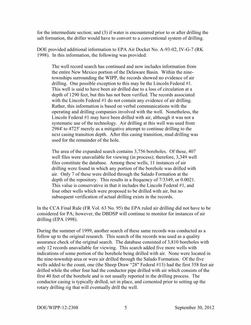
DOE provided additional information to EPA Air Docket No. A-93-02, IV-G-7 (RK
1998). In this information, the following was provided:
The well record search has continued and now includes information from
the entire New Mexico portion of the Delaware Basin. Within the nine-
townships surrounding the WIPP, the records showed no evidence of air
drilling. One possible exception to this may be the Lincoln Federal #1.
This well is said to have been air drilled due to a loss of circulation at a
depth of 1290 feet, but this has not been verified. The records associated
with the Lincoln Federal #1 do not contain any evidence of air drilling.
Rather, this information is based on verbal communications with the
operating and drilling companies involved with the well. Nonetheless, the
Lincoln Federal #1 may have been drilled with air, although it was not a
systematic use of the technology. Air drilling at this well was used from
2984' to 4725' merely as a mitigative attempt to continue drilling to the
next casing transition depth. After this casing transition, mud drilling was
used for the remainder of the hole.
The area of the expanded search contains 3,756 boreholes. Of these, 407
well files were unavailable for viewing (in process); therefore, 3,349 well
files constitute the database. Among these wells, 11 instances of air
drilling were found in which any portion of the borehole was drilled with
air. Only 7 of these were drilled through the Salado Formation at the
depth of the repository. This results in a frequency of 7/3349, or 0.0021.
This value is conservative in that it includes the Lincoln Federal #1, and
four other wells which were proposed to be drilled with air, but no
subsequent verification of actual drilling exists in the records.
In the CCA Final Rule (FR Vol. 63 No. 95) the EPA ruled air drilling did not have to be
considered for PA; however, the DBDSP will continue to monitor for instances of air
drilling (EPA 1998).
During the summer of 1999, another search of these same records was conducted as a
follow up to the original research. This search of the records was used as a quality
assurance check of the original search. The database consisted of 3,810 boreholes with
only 12 records unavailable for viewing. This search added five more wells with
indications of some portion of the borehole being drilled with air. None were located in
the nine-township area or were air drilled through the Salado Formation. Of the five
wells added to the count, one (the Sheep Draw “28" Federal #13) had the first 358 feet air
drilled while the other four had the conductor pipe drilled with air which consists of the
first 40 feet of the borehole and is not usually reported in the drilling process. The
conductor casing is typically drilled, set in place, and cemented prior to setting up the
rotary drilling rig that will eventually drill the well.

DOE/WIPP-12-2308 September 30, 2012 6
The records on the new wells spudded during the last year (September 1, 2011 through
August 31, 2012) are being checked as they become available at the NMOCD Internet
site for instances of air drilling. The records can be submitted to the NMOCD offices as
late as two years after the well has been drilled. The record review is an ongoing process.
None of the records reviewed to date have indicated any additional instances of air
drilling. Air drilling is not a common practice in the vicinity of the WIPP Site. Table 3
shows the known indications of air drilling that have occurred in the New Mexico portion
of the Delaware Basin.
2.2 Shallow Drilling Events
The criteria in 40 CFR Part 194.33 is that the CCA and subsequent CRAs must
adequately and accurately characterize the frequency of shallow drilling within the
Delaware Basin, as well as, support the assumptions and determinations, particularly
those that limit consideration of shallow drilling events based on the presence of
resources of similar type and quantity found in the controlled area. The EPA defined
shallow drilling as “drilling events in the Delaware Basin that do not reach a depth of
2,150 feet below the surface relative to where such drilling occurred.” The DOE
concluded in CCA, Appendix SCR that shallow drilling could be removed from PA
consideration based on low consequence. As a result, the DOE did not include shallow
drilling in its PA drilling rate calculations and did not include any reduction in shallow
drilling rates during the active and passive institutional control periods. In CCA,
Compliance Application Review Document (CARD) 33, the EPA accepted the DOE’s
finding that shallow drilling would be of low consequence to repository performance and
need not be included in the PA.
Although the EPA has agreed, in CARD 33, shallow drilling is of low consequence and
could be eliminated from the PA, the DBDSP collects data on wells reported to be drilled
within the boundaries of the Delaware Basin. Table 4 shows a breakdown of the various
types and number of shallow wells located within the Delaware Basin. The shallow
drilling rate can be calculated as follows: number of holes less than 2,150 ft drilled in the
last 100 years times 10,000 years divided by the area of the Delaware Basin (23,102.1
square kilometers (km2)) divided by 100 years. As of August 31, 2012, there were 6,664
boreholes less than 2,150 feet. Applying the formula results in the following: 6,664
boreholes x 10,000 years / 23,102.1 km2 / 100 years. This results in a shallow drilling
rate for 2012 of 28.8 boreholes per km2 over 10,000 years.
2.3 Deep Drilling Events
In accordance with the criteria, the DOE used the historical rate of drilling for resources
in the Delaware Basin to calculate a future drilling rate. In particular, in calculating the
frequency of future deep drilling, 40 CFR §194.33(b)(3)(i) (EPA 1996) provided the
following criteria to the DOE:

DOE/WIPP-12-2308 September 30, 2012 7
Identify deep drilling that has occurred for each resource in the Delaware
Basin over the past 100 years prior to the time at which a compliance
application is prepared.
The DOE used the historical record of deep drilling for resources below 2,150 feet that
has occurred over the past 100 years in the Delaware Basin. This was chosen because it
is the depth of the repository, and the repository is not directly breached by boreholes less
than this depth. In the past 100 years, deep drilling occurred for oil, gas, potash, and
sulfur. These drilling events were used in calculating a rate for deep drilling for the PA
as discussed in CCA, Appendix DEL. The period of calculation used was from January
1896 through June 1995. Historical drilling for purposes other than resource exploration
and recovery (such as WIPP Site investigation) were excluded from the calculation in
accordance with criteria provided in 40 CFR §194.33.
In the Delaware Basin, deep drilling events are usually associated with oil and gas
drilling. Commercial sources and state regulating offices are used to identify these
events. The DBDSP collects data on drilled wells within the Delaware Basin, making no
distinction between resources. One combined Microsoft®
SQL Server®
based well
tracking application is maintained on hydrocarbon wells for Texas and New Mexico. As
information on wells is acquired, it is entered into this well tracking application. The
Texas portion of the well tracking application contains information only on the current
status of the well, when it was drilled, its location, the name of the operator, and the total
depth of the well. The Texas portion is used only for calculating the drilling rate. The
New Mexico portion contains the same basic information as Texas, along with the
required features, events, and processes for PA-related drilling events.
The DBDSP continues to monitor hydrocarbon drilling activity and any new potash,
sulfur, water, or monitoring wells for deep-drilling events. Information from the drilling
of these wells is added to the well tracking application maintained for these resources.
During the last year, there were 980 new wells added to the well tracking application.
Most of the wells were drilled for hydrocarbon extraction and were deep-drilling events.
Fifteen of these new wells are in the nine-township area immediately surrounding the
WIPP Site. Table 5 shows the number and type of deep wells located in the Delaware
Basin.
2.4 Past Drilling Rates
The EPA provided a formula for calculating the current drilling rate or intrusion rate
when 40 CFR Part 194 was promulgated. The formula is as follows: number of holes
drilled in the last 100 years times 10,000 years divided by the area of the Delaware Basin
(23,102.1 km2) divided by 100 years (1897-1996, the year the CCA was submitted). The
DBDSP uses deep drilling events of any resource (potash, oil, gas, water, etc.) to
calculate the drilling or intrusion rate.
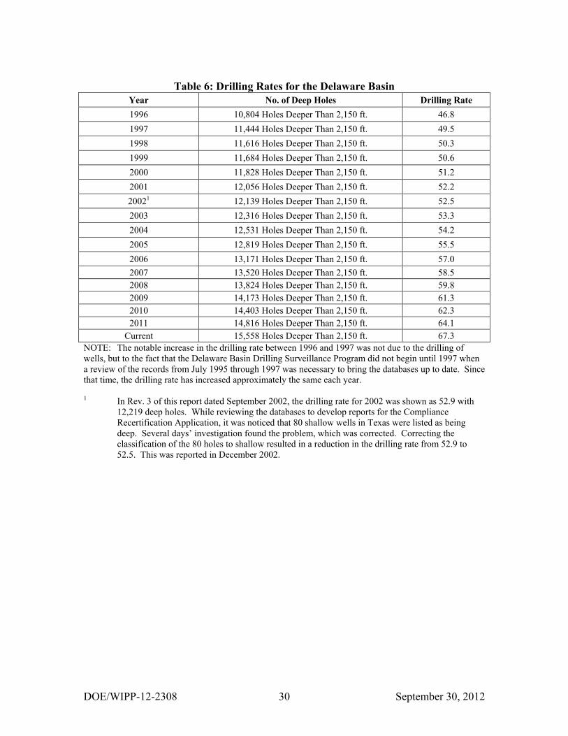
The drilling rates since the submittal of the CCA in 1996 are shown in Table 6. The large
increase between 1996 and 1997 is the result of updating the databases with information

DOE/WIPP-12-2308 September 30, 2012 8
from June 1995 through August 1997. Also, the 100-year period is considered a moving
period, in which 100 years worth of data are used each time the calculation is performed.
As each new year’s data are added, the oldest year’s data are dropped. For example, the
drilling rate was calculated in 1999 by using the data from 1900 through 1999. In 2000,
the data from 1901 through 2000 were used to calculate the drilling rate.
2.5 Current Drilling Rate
The calculated deep drilling rate for 2012 was derived from the information provided in
Table 5. There were 15,559 boreholes deeper than 2,150 feet. One well was removed
from the count because it is no longer within the 100-year interval. This brings the total
deep well count to 15,558 boreholes. Applying the formula results in the following:
15,558 boreholes x 10,000 years / 23,102.1 km2 / 100 years. This results in a drilling rate
of 67.3 boreholes per km2 over 10,000 years.
This is an increase from the 46.8 boreholes per km2 reported in the CCA. The deep
drilling rate is anticipated to rise for several more years before it begins to drop. This is
because of the 100-year moving time frame used for drilling results. As new wells are
added to the count, wells older than 100 years are dropped. This year, the first well,
spudded in 1911, was dropped from the count because it was older than 100 years. The
next well won’t be removed from the count, due to the 100-year time frame, until 2014.
In the meantime, a number of new wells will continue to be added each year due to
ongoing oil and gas drilling activity, thus increasing the rate.
2.5.1 Nine-Township Area Drilling Activities
From September 1, 2011 to August 31, 2012, there were sixteen new wells spudded in the
nine-township area immediately surrounding the WIPP Site. Two new wells were drilled
in the one-mile area surrounding the WIPP Site with one to the southwest and one to the
southeast of the site. Figure 3 shows the status of known hydrocarbon wells drilled
within the one-mile area of the WIPP Site. Of the sixteen new wells, eleven were drilled
in Eddy County and five in Lea County. Three of the wells are to the north of the site,
five are to the east, and eight are to the south of the WIPP Site.
2.5.2 Drilling Activities Outside the Nine-Township Area
In the New Mexico portion of the Delaware Basin outside of the nine-township area,
there were 168 new wells spudded during the reporting period of September 1, 2011
through August 31, 2012. Of the 168 wells, 121 are located in Eddy County and 47 are
in Lea County.
In the Texas portion of the Delaware Basin, 717 new wells were spudded during the
reporting period. The DBDSP monitors drilling activities in portions of seven counties
and all of one county (Loving). A majority of the wells were drilled in Loving, Reeves,
Ward, and Culberson counties.

DOE/WIPP-12-2308 September 30, 2012 9
2.6 Castile Brine Encounters
The WIPP PA included the assumption that a borehole results in the establishment of a
flow path between the repository and a pressurized brine pocket that might be located
beneath the repository in the Castile Formation. Research was performed in an attempt to
verify this assumption. Studies recorded a total of 27 out of 620 wells encountering
pressurized brine in the Castile Formation; of these, 25 were hydrocarbon wells scattered
over a wide area in the vicinity of the WIPP Site. The remaining wells, ERDA 6 and
WIPP 12, were drilled in support of WIPP Site characterization.
As indicated earlier, the search of the records performed in 1999 for instances of air
drilling also looked for instances of pressurized brine. Although the search of the records
noted a number of instances of encounters with sulfur water and brine water, only the
original 27 were found to have been pressurized brine encounters in the Castile
Formation.
The DBDSP researches the well files of new wells drilled in the New Mexico portion of
the Delaware Basin each year looking for instances of encounters with pressurized brine.
The program also sends out an annual survey to operators of new wells asking if they
encountered pressurized brine during the drilling process. As of this report, none of the
records reviewed indicated encounters with pressurized brine during the drilling of new
wells spudded in the New Mexico portion of the Delaware Basin between September 1,
2011 and August 31, 2012.
Seven wells drilled since the 1996 CCA have encountered Castile Brine. Six were
identified when WIPP Site personnel performing field work talked to area drillers. The
other encounter was reported by an operator in the Annual Survey of area drillers. The
new encounters have been in areas where Castile Brine is expected to be encountered
during the drilling process. Table 7 shows known Castile Brine encounters in the vicinity
of the WIPP Site.
In the 1996 CCA, the probability for encountering a Castile Brine reservoir was
calculated at 8 percent with 27 hits out of 345 possibilities. In the Performance
Assessment Verification Test (PAVT), the EPA mandated a range of 1 percent to 60
percent. These higher values did not influence the predicted performance of the
repository. The CRA-2004 continued to use the higher values and a probability for
encountering a Castile Brine reservoir was not calculated. The CRA-2009 uses the
values from the PAVT. However, due to the increased drilling in the area it was
necessary to see if the original value was still valid. The same parameters were used and
the rate was calculated at 5 percent with 34 brine encounters out of 678 possibilities.
This is a reduction of 3 percent over the last eleven years.
2.7 Borehole Permeability Assessment - Plugging Practices
The hydrocarbon well plugging assumptions used for the borehole permeability
assessment remain valid. The regulations in place during the submittal of the CCA, the

DOE/WIPP-12-2308 September 30, 2012 10
CRA-2004, and the CRA-2009 have not changed. The assessment will not change unless
the regulations change to allow a different method of plugging. Regulations require the
well be plugged in a manner that will permanently confine oil, gas, and water in the
separate strata in which they were originally found. These regulations require a notice of
intent to plug from the operator to the regulating agency. This notice includes a diagram
of the well bore and the placement of the plugs. A 24-hour notice to the NMOCD or to
the Bureau of Land Management (BLM) is required before plugging may commence.
Approximately 900 wells in the vicinity of the WIPP Site are in the KPLA. Under
NMOCD R-111-P regulations, the operator is required to provide a solid cement plug
through the salt section and any water-bearing horizon in addition to installing a bridge
plug above the perforations. The above requirement provides protection to mineralized
potash areas and workings by requiring a continuous plug so there is virtually no chance
of flooding nearby mines either as they are developed or during their operation.
In the New Mexico portion of the Delaware Basin, the DBDSP retrieves a copy of the
plugging report from the NMOCD Internet site when a well has been plugged and
abandoned. This information is added to the records maintained by the DBDSP on each
well drilled within the Delaware Basin. By maintaining records in such a fashion, should
the regulations change and the plugging methods differ from what is now occurring, a
trend would be noticed and the borehole permeability assessment revisited. Table 8
shows various plug information on the wells plugged and abandoned within the New
Mexico portion of the Delaware Basin in the last year.
Compliance Certification Application, Appendix MASS, Attachment 16-1 describes the
development of a conceptual model for long-term performance of plugged boreholes.
The study did not attempt to predict the effectiveness of plugs, but to identify the location
and physical characteristics of plugs, which might be important to performance
assessment. Guidance in 40 CFR Part 194.33 states, “Performance assessments should
assume that the permeability of sealed boreholes will be affected by natural processes,
and should assume that the fraction of boreholes that will be sealed by man equals the
fraction of boreholes which are currently sealed in the Delaware Basin.” The criteria also
state that “...drilling practices will remain as those of today.” Only wells plugged in the
New Mexico portion of the Delaware Basin were used for the study and only wells
drilled after 1988, when the current plugging regulation went into effect, were used. The
results of this study indicated the PA should assume a 100 percent plugging frequency.
To determine the typical configuration and composition of a borehole plug, the study
considered plugging practices to arrive at a model depicting six different types of
plugging configurations (see Figure 4):
Type I Plugs will be located at the transition between the surface and intermediate
casings and the transition between the intermediate and production
casings. This area is usually the top of the Salado Formation and the
bottom of the Castile Formation, roughly 800 feet and 4,000 feet below
the surface, respectively.

DOE/WIPP-12-2308 September 30, 2012 11
Type II This plugging configuration has a portion of the production casing
salvaged. Where the production casing was cut, a plug must be installed.
If a plug occurs between 2,150 feet and 2,700 feet (above the hypothetical
brine pocket) and the other plugs occur at the top of the Salado Formation
and below the Castile Formation, it is considered a Type II configuration.
Type III This configuration is the same as above except the removed production
casing plug occurs above 2,150 feet.
Type IV Extra plugs, in addition to those of Type II, have been emplaced above
2,150 feet.
Type V The minimum regulatory requirements require a surface plug and a plug
occurring at the bottom, provided no water-bearing zones were
encountered. This type of plugging configuration is not common.
Type VI This configuration has a solid cement plug through a significant portion of
the salt section. This configuration, like the others, may have additional
plugs above and below the salt-section plug.
There were 25 wells plugged during the reporting period. Four wells are in the nine-
township area and 21 are outside the nine-township area. Three of the 25 wells are in the
KPLA. Two wells have total depth of less than 300 feet. These two wells will not be
considered in the permeability assessment update. Therefore, 23 of the 25 wells will be
used in the permeability assessment update (see Table 9 and Table 10).
2.8 Seismic Activity in the Delaware Basin
Known seismic events occurring in Southeast New Mexico and West Texas, specifically
in the Delaware Basin, are recorded in a database and on a map. This information is
obtained every quarter in a report from the New Mexico Institute of Mining and
Technology, Socorro, New Mexico, utilizing data from an array of nine seismographs in
the vicinity of the WIPP Site (NMIMT 2012).
During the reporting period there were five seismic events recorded in the Delaware
Basin. Two seismic events occurred in Reeves County with magnitudes of 1.5 and 2.0.
Three seismic events occurred in Eddy County with magnitudes of 1.2, 1.6, and 2.4. One
seismic event in Eddy County which occurred on 3/18/2012 with a magnitude of 2.4 can
be attributed to a mine collapse. Table 11 provides information on recorded seismic
events, which have occurred in the Delaware Basin.
2.9 Secondary and Tertiary Recovery
Secondary recovery is defined by the oil industry as the first improved recovery method
of any type applied to a reservoir to produce oil not recoverable by primary recovery

DOE/WIPP-12-2308 September 30, 2012 12
methods. Waterflooding is one such method. This method involves pumping water
through the existing perforations in a well. As the water is pumped into a formation, it
stimulates production of oil or gas in other nearby wells. This is a proven method of
recovering hydrocarbons. Waterflooding has been a popular form of secondary recovery
for over 40 years. Waterflooding can be accomplished by one injection well or several
injection wells in the immediate vicinity of other producing wells.
In the New Mexico portion of the Delaware Basin, there are three major waterflood
projects and several one and two injection well operations. One of the major waterflood
projects in the area is the El Mar, located in T26S-R32E, on the Texas border. At one
time, this project had 31 permitted injection wells. Currently, there are three injection
wells actively injecting water. The remaining wells are either shut-in, temporarily
abandoned, or plugged and abandoned. The Paduca waterflood project, located in T25S-
R32E, has six permitted injection wells with five injecting water into the formation. The
third major waterflood project in this area is the Indian Draw, located in T22S-R28E, has
nine permitted injection wells and is currently injecting into six of its permitted wells.
Tertiary recovery is defined by the oil industry as the use of any improved recovery
method to remove additional oil after secondary recovery. At the time of this report,
there are no known tertiary recovery projects being operated in the vicinity of the WIPP
Site, although several projects are being operated by oil companies in the Texas portion
of the Delaware Basin using CO2.
2.9.1 Nine-Township Injection Wells
Secondary recovery projects occurring in the nine-township area are on a small scale.
There are six injection wells located in the nine-township area surrounding the WIPP
Site. ConocoPhillips Company operates two injection wells northwest of the site in the
Cabin Lake field. The other four injection wells are operated by OXY USA INC and are
located south and east of the site. The six wells are injecting into the Brushy Canyon
Formation of the Delaware Mountain Group at a depth of approximately 7,200 feet.
Figure 5 shows a typical injection or salt water disposal well configuration. Table 12
provides information on the injection wells located in the nine-township area.
2.9.2 Nine-Township Salt Water Disposal Wells
The most common type of injection well is for the disposal of brine water coming from
the producing formation in oil and gas wells. Figure 6 shows the location of active
injection and salt water disposal wells in the nine-township area. Most producing oil and
gas wells produce water along with oil or gas. Salt Water Disposal (SWD) wells have
become necessary as a result of the EPA’s ruling that formation water may no longer be
disposed of on the surface. The oil companies now dispose of this water by injecting it
into approved SWD wells.
There are currently fifty-five SWD wells located in the nine-township area surrounding
the WIPP Site. Three operators, Devon Energy Production Company, LP, OXY USA

DOE/WIPP-12-2308 September 30, 2012 13
INC, and Yates Petroleum Corporation, operate the majority of the SWD wells. Injection
depths range from 3,400 feet to 8,500 feet. During the last year, based on injection
records, the three companies operated within their maximum permitted injection pressure.
The volume of disposed brine water depends on the number of producing oil and gas
wells maintained by the operator in the immediate vicinity of the SWD well. Table 12
provides information on SWD and injection wells in the nine-township area.
2.10 Mining
Resources found in the Delaware Basin that can be mined are potash, sulfur, caliche,
gypsum, and halite (NMBMMR 1995).
2.10.1 Potash Mining
Potash mining in the immediate vicinity of the WIPP Site continues as reported in CCA,
Appendix DEL and CRA-2004, Appendix DATA. Figure 7 shows the location and the
extent of the potash mines in the vicinity of the WIPP Site. There have been several
changes to the companies that operate in the area, most notably, only two potash
companies are actively mining. No plans have been promulgated by either company to
sink new shafts or develop new mines; however, a new company, Intercontinental
Potash, has procured leases to the east of the WIPP site and proposes to develop two
separate underground mines in order to mine polyhalite (a type of potash).
In August 1996, Mississippi Potash (a subsidiary of Mississippi Chemical Corporation)
purchased the assets of New Mexico Potash Corporation and Eddy Potash, Inc. These
plants were renamed Mississippi East and Mississippi North, respectively. In early 2004,
Mississippi Potash sold its Carlsbad properties to Intrepid Mining LLC, a Denver based
mining company. Recently the company changed the name to Intrepid Potash – New
Mexico, LLC. The former Eddy Potash, Inc. mine (Mississippi North) is currently shut
down.
The other potash producer in the area is The Mosaic Company, formerly known as IMC
Kalium Potash, which was a wholly-owned subsidiary of IMC Global. Western Ag-
Minerals was purchased by IMC Global in September 1997. This acquisition doubled the
potash reserves for IMC Kalium. IMC Global merged with Freeport-McMoRan, a major
world potash producer, in December 1997 with IMC Global as the surviving entity in the
transaction. In 2004, IMC Global and Cargill, Inc. merged to form The Mosaic
Company.
2.10.2 Sulfur Extraction
The only sulfur mining activity within the Delaware Basin was conducted by Freeport-
McMoRan Sulphur, Inc., formerly operated by Pennzoil Sulphur Company. The mine is
located in Culberson County, Texas. The mine recovered sulfur utilizing the Frasch
process, which consists of a hole drilled into the sulfur bearing formation and then cased.
The next step involves the placement of three concentric pipes within the protective

DOE/WIPP-12-2308 September 30, 2012 14
casing to facilitate pumping superheated water down the hole, melting the sulfur, then
using compressed air to lift the molten sulfur to the surface. The mine was operated until
it permanently ceased production on June 30, 1999. Abandonment and salvage
operations continued until early summer of 2000.
2.10.3 Solution Mining
Solution mining is the process by which water is injected into a mineral formation,
circulated to dissolve the mineral, with the solution then pumped back to the surface
where the minerals are removed from the water, usually by evaporation. There are
several brine mines or wells in the area, two in New Mexico and ten in Texas (see Figure
8), that use this process to provide a brine solution for area drilling operators to use in the
drilling process. These are shallow wells using injected fresh water to dissolve salt into a
brine solution.
Brine wells are classified as Class II injection wells. In the Delaware Basin, the process
involves injecting fresh water into a salt formation to create a saturated brine solution,
which is then extracted and used as a drilling agent when drilling a new well. These
wells are tracked by the DBDSP on a continuing basis. Table 13 provides the status of
brine wells in the Delaware Basin.
A moratorium on new brine wells was enacted by the NMOCD in mid November 2008
due to the collapse of two brine wells in the vicinity of Loco Hills, New Mexico, neither
of which is located in the Delaware Basin. One was in an isolated area and was actively
producing brine for sale. This well collapsed in July 2008. The second well to collapse
was located just outside of Loco Hills and had been recently plugged and abandoned.
This well collapsed in early November 2008.
A brine well is closely being monitored by the NMOCD as it fits the geological profile of
the two collapsed wells. This well is located within the Carlsbad city limits and is within
the New Mexico portion of the Delaware Basin. It was voluntarily plugged and
abandoned by the operator in October 2008.
In early 1997, Mississippi Potash proposed to set up a pilot potash solution mining
project at the former Eddy Potash, Inc. mine located north of the WIPP Site and outside
of the Delaware Basin. The BLM was provided with the necessary documentation to
acquire a permit to operate the pilot project, but the project was postponed. In March
2002, Mississippi Potash again applied for a permit to operate a pilot in-situ potash
solution mining project. In May 2002, the project was given approval to proceed by the
BLM. Intrepid Potash, formerly Mississippi Potash, has continued with the project by
developing a required Environmental Impact Statement (EIS), which was approved by
the BLM on March 19, 2012. Construction is occurring to install pipelines, wells, and
evaporation ponds. The in-situ solution mining process will occur at the former Eddy
Potash, Inc. mine, which is outside of the Delaware Basin however the evaporation ponds
used to collect the potash are located just inside of the Delaware Basin.

DOE/WIPP-12-2308 September 30, 2012 15
In the late 1960s, Conoco Minerals installed a pilot solution mining project on leases it
held on the former AMAX property north of the Delaware Basin and the WIPP Site. The
project was designed to test solution mining of potassium minerals and consisted of one
injection well and three withdrawal wells, but the potash ore zone was deemed too thin to
make this method viable at this location.
2.11 New Drilling Technology
New drilling methods are researched by the DBDSP for impacts to the drilling methods
currently used in the area. Recently, the NMOCD issued a new pit rule 19.15.17 NMAC,
consequently most operators are now using the closed-loop system to drill wells on state
land.
2.12 Alternative Energy Activities
The DBDSP researches alternative energy activities that may have impact on PA such as
compressed air storage from wind farm activities. Alternative energy activities that may
be conducted in the Delaware Basin include solar, wind, and geothermal power.
Currently there are no known geothermal power projects being performed in the
Delaware Basin. Solar power is currently being pursued in the Delaware Basin. Sun
Edison completed construction of a new photovoltaic solar power plant on the southern
edge of the Carlsbad city limits, which is located within the Delaware Basin. Wind
power is a proven technology and has been ongoing in the Delaware Basin since 1995.
Two wind farms operated by FPL Energy are located in the western mountains of the
Delaware Basin. One farm operates approximately 140 turbines and the second one has
40 turbines. Both are located adjacent to each other approximately 10 miles south of the
Guadalupe Mountains National Park and 75 miles southwest of the WIPP Site. The
DBDSP will continue to monitor alternative energy activities.
3.0 Survey of Well Operators for Drilling Information
The DBDSP surveys local well operators annually to acquire information on drilling
practices normally not available on the Sundry notices supplied to the local state and
federal offices by the operator or through commercial sources maintained by the DBDSP.
Participation in the survey is voluntary. This survey requests information on other items
of interest to the WIPP Project such as hydrogen sulfide (H2S) encounters, Castile Brine
encounters, or whether any section of the well was drilled with air. The DBDSP
personnel review the records on new wells drilled to look for the above data. The survey
provides an additional source of information on drilling activities in the New Mexico
portion of the Delaware Basin.
The first survey of area operators was performed July 1999 and had been sent out each
July until 2004. An annual survey was not performed in July 2004. The survey for 2004
was moved to January 2005 and is performed in January of each year. With this change,
results from the annual survey will be included in the annual report for that year as there

DOE/WIPP-12-2308 September 30, 2012 16
will be nine months for surveys to be returned instead of two months. As of this report,
no return correspondence has been received from local well operators.
4.0 Summary - 2012 Delaware Basin Drilling Surveillance Program
No new instances of air drilling.
No Castile Brine encounters reported.
The drilling rate has increased to 67.3 boreholes per square kilometer.
No change in injection and salt water disposal activities.
Sixteen wells spudded in the nine-township area.
One hundred sixty-eight wells spudded outside the nine-township area in New
Mexico.
Seven hundred seventeen wells spudded in the Texas portion of the Delaware
Basin.

DOE/WIPP-12-2308 September 30, 2012 17
5.0 References
Kirkes, G. Ross, Current Drilling Practices Near WIPP, 1998, EPA Air Docket No. A-
93-02, IV-G-7, January 22, 1998
New Mexico Bureau of Mines and Mineral Resources (NMBMMR), 1995, Evaluation of
Mineral Resources at the Waste Isolation Pilot Plant, Final Report, Vols. I-IV
New Mexico Institute of Mining and Technology (NMIMT), 2011, Seismicity of the
WIPP Site for the Period July 1, 2011 through September 30, 2011, Socorro, New
Mexico
New Mexico Institute of Mining and Technology (NMIMT), 2012, Seismicity of the
WIPP Site for the Period October 1, 2011 through December 31, 2011, Socorro, New
Mexico
New Mexico Institute of Mining and Technology (NMIMT), 2012, Seismicity of the
WIPP Site for the Period January 1, 2012 through March 31, 2012, Socorro, New
Mexico
New Mexico Institute of Mining and Technology (NMIMT), 2012, Seismicity of the
WIPP Site for the Period April 1, 2012 through June 30, 2012, Socorro, New Mexico
U.S. Department of Energy (DOE), 2011, DOE/WIPP-11-2308, Delaware Basin
Monitoring Annual Report, September 2011
U.S. Department of Energy (DOE), 1996, DOE/CAO-1996-2184, Title 40 CFR Part 191
Compliance Certification Application for the Waste Isolation Pilot Plant, October 1996
U.S. Department of Energy (DOE), 2004, DOE/WIPP 2004-3231, Title 40 CFR Part 191
Compliance Recertification Application for the Waste Isolation Pilot Plant, March 2004
U.S. Department of Energy (DOE), 2009, DOE/WIPP 2009-3424, Title 40 CFR Part 191
Compliance Recertification Application for the Waste Isolation Pilot Plant, March 2009
U.S. Environmental Protection Agency (EPA), 1996, Title 40 CFR Part 194, Criteria for
the Certification and Re-Certification of the Waste Isolation Pilot Plant’s Compliance
with the 40 CFR Part 191 Disposal Regulations
U.S. Environmental Protection Agency (EPA), 1998, Title 40 CFR Part 194, Criteria for
the Certification and Recertification of the Waste Isolation Pilot Plant’s Compliance with
the Disposal Regulations: Certification Decision; Final Rule
Washington TRU Solutions LLC, 2008, WP 02-PC.02, Rev. 4, Delaware Basin Drilling
Surveillance Plan, May 2012

DOE/WIPP-12-2308 September 30, 2012 18
Figure 1: WIPP Site, Delaware Basin, and Surrounding Area
~ CHAVES NEW MEXICO -~9
GAINES
LEA OTERO
EDDY AlllREWS
ANDREWS
ECTOR
JEFF DAVIS PECOS
*''? -1:-~
o'5 ~ , ;?'?
G M \ PRESIDIO E X
t 7 I ill I I 1 I liidl l I c
~ DELAWARE BASIN BF~EWSTER 0

DOE/WIPP-12-2308 September 30, 2012 19
Figure 2: Typical Well Structure and General Stratigraphy Near the WIPP Site

DOE/WIPP-12-2308 September 30, 2012 20
Figure 3: Oil and Gas Wells within One Mile of the WIPP Site
7
. .. T22S-R30E
18
0 Salt Water Disposal Well
• Oil Well
• Gas Well
() Dry Hole
• Plugged Oil Well
• •
17
0 N
CJ Bureau Land Management
A CJ Department of Energy
CJ State
CJ Private
STATUS OF HYDROCARBON ACTIVITY WITHIN ONE MILE OF THE WIPP SITE
September 1, 2012
10 I I
• • 14
•
2 mi US

DOE/WIPP-12-2308 September 30, 2012 21
Figure 4: Typical Borehole Plug Configurations in the Delaware Basin
TYPE I SURFACE ---v7777~
APPROXIMATELY 400' -800'
TYPE II TYPE Ill TYPE IV
I L
I L
I _j
I _j
TYPE V TYPE VI
POSTULATED BRINE FP'()OQIOLj_ ___ _l':"':]"::j ____ L ___ l::"::"["j_ ___ _j ____ ~~~~ 2,700' I
APPROXIMATELY 4,000'
OPTIONAL PLUG C = ::J CEMENT PLUG V/Z/23
NOT TO SCALE
PLUGGED THROUGH SALT

DOE/WIPP-12-2308 September 30, 2012 22
Figure 5: Typical Injection or Salt Water Disposal Well (SWD)
CHRISTMAS TREE
TUBING HEAD
CASING HEAD
CASING HEAD (BRADENHEAD)
PLUG
('
\
>
~CORROSION INHIBITING FLUID SURFACE CASING INTERMEOII\TE CASING PRODUCTION CASING TUBING
/
/
/ /
/
CEMENT SURFACE CASING
INTERMEDIATE CASING PRODUCTION CASING
ANNULAR SPACE TUBING
CENTRALIZER
CORROSION INHIBITING FLUID
NOT TO SCALE
ANNULAR SPACE
~ 111··;~·.· . . ·.::··:.·· ;~ >
i f I ·.~ ~ • • ••
SURFACE CASING w · ~ CENTRALIZER CEMENT CORROSION
INTERMEDIATE CASING INHIBITING PRODUCTION CAS ING FLUID (
ANNULAR T~~~~ \.._ib_J)
VALVE
SURFACE CASING
CORROSION INHIB ITING FLUID
INTERMMEDII\TE CASING
TUBING
FLUID FLOW
~ ~(. • ~~~~~~~g~;LUID • .. PACKER
PRODUCTION CASING · CEMENT i~PERFORATIONS
~/
/ PRODUCTION CASING
PACKER

DOE/WIPP-12-2308 September 30, 2012 23
Figure 6: Active Injection and SWD Wells in the Nine-Township Area
N
A • Injection Well
e Salt Water Disposal Well

DOE/WIPP-12-2308 September 30, 2012 24
Figure 7: Potash Mining in the Vicinity of the WIPP Site

DOE/WIPP-12-2308 September 30, 2012 25
Figure 8: Active Brine Well Locations in the Delaware Basin

DOE/WIPP-12-2308 September 30, 2012 26
Table 1: Nine-Township Area Casing Sizes
Casing Size Surface Casing Intermediate Casing Production Casing
16" 0 0 0
13 3/8" 6 0 0
11 3/4" 5 0 0
10 3/4" 0 0 0
9 5/8" 0 6 0
8 5/8" 0 5 0
7 5/8" 0 0 0
7" 0 0 2
5 1/2" 0 0 9
NOTE: There were sixteen wells drilled in the nine-township area between September 1, 2011 and August
31, 2012. Eleven of the wells had complete records available on casing sizes. The other wells had
partial records available or had just recently been spudded.
Table 2: Nine-Township Area Bit Sizes
Bit Size Surface Hole Intermediate Hole Production Hole
20" 0 0 0
17 1/2" 6 0 0
14 3/4" 5 0 0
13 3/8" 0 0 0
12 3/4" 0 0 0
12 1/4" 0 6 0
11" 0 0 0
10 5/8" 0 5 0
9 7/8" 0 0 0
8 3/4" 0 0 4
8 1/2" 0 0 1
7 7/8" 0 0 6
7 3/4" 0 0 0
7" 0 0 0
6 1/8 " 0 0 0
NOTE: Of the sixteen wells drilled in the nine-township area, complete records were available on eleven
wells.

DOE/WIPP-12-2308 September 30, 2012 27
Table 3: Air-Drilled Wells in the New Mexico Portion of the Delaware Basin
# Location Well Name and No. Spud Date Status Well Information
1 21S-28E-33 Richardson & Bass #1 7/27/1961 P&A
Air drilled through the salt. Between
2,545' and 2,685' encountered water
and changed from air to mud-based
drilling.
2 21S-32E-26 Lincoln Federal Unit #1 4/1/1991 P&A
Lost circulation at 1,290'. Hole was
dry drilled to 1,792'. Supposedly, air
drilled from 2,984' to 4,725'
3 23S-26E-17 Exxon "17" Federal #1 8/1/1989 Gas Well Air drilled through the salt from 575'
to 2,707'.
4 23S-28E-11 CP Pardue #1 10/28/1958 P&A Air drilled through the salt from 390'
to 2,620'
5 23S-28E-11 Amoco Federal #1 8/4/1979 Oil Well Air drilled from 475' to 9,700'.
6 23S-28E-11 Amoco Federal #3 2/28/1980 Oil Well Air drilled from 6,271' to 9,692'.
7 23S-28E-23 South Culebra Bluff Unit #3 1/21/1979 Oil Well Air drilled from 6,345' to 8,000'.
8 23S-28E-23 South Culebra Bluff Unit #4 8/9/1979 Oil Well Air drilled from 450' to 9,802'.
9 24S-31E-03 Lilly "ALY" Federal #2 5/1/1994 Oil Well Air drilled conductor hole to 40'.
10 24S-31E-03 Lilly "ALY" Federal #4 5/16/1994 Oil Well Air drilled conductor hole to 40'.
11 24S-34E-04 Antelope Ridge Unit #2 9/13/1962 Gas Well
Attempted to drill with gas. Had to
convert to water at 1,035'. Tried again
several times at different depths.
12 24S-34E-09 Federal "9" Com #1 12/3/1963 Gas Well Hit water while gas drilling at 4,865'.
13 24S-34E-13 Federal Johnson #1 6/23/1958 P&A
Proposed to drill with air, but no
information in the records indicate air
drilling.
14 26S-32E-20 Russell Federal #1 3/16/1966 Oil Well Drilled with air to 1,330'.
15 26S-32E-36 North El Mar Unit #44 2/19/1959 Oil Well
Proposed to drill with air, but no
information in the records indicate air
drilling.
Wells Drilled after Supplemental Information Provided to the EPA Docket in 1997.
16 22S-26E-28 Sheep Draw "28" Federal #13 7/1/1997 Oil Well Air drilled the first 358'.

DOE/WIPP-12-2308 September 30, 2012 28
Table 4: Shallow Well Status in the Delaware Basin
Well Type Texas New Mexico Totals
Core Hole 31 2 33
Dry Hole 348 152 500
Gas Well 9 9 18
Injection Well 5 1 6
Junked and Abandoned Well 65 31 96
Oil Well 104 36 140
Oil and Gas Well 2 0 2
Plugged Gas Well 1 4 5
Plugged Oil Well 19 19 38
Plugged Brine Well 2 3 5
Plugged Salt Water Disposal Well 0 5 5
Drilling or Waiting on Paperwork 523 85 608
Brine Well 1 2 3
Salt Water Disposal Well 0 3 3
Service Well 12 0 12
Stratigraphic Test Hole 1,170 0 1,170
Sulfur Core Hole 502 0 502
Potash Core Hole 0 971 971
Water Well 1,706 590 2,296
WIPP Well 0 207 207
Other (Mine Shafts, Gnome Project Wells) 0 44 44
TOTALS 4,500 2,164 6,664
NOTE: Only the known holes that occur in the Delaware Basin are listed in the above table. The 608
wells under the listing of “Drilling or Waiting on Paperwork” do not have an associated depth
until one has been reported on paperwork. These are listed as shallow wells but may eventually be
placed in the deep classification when a depth has been listed in the paperwork.

DOE/WIPP-12-2308 September 30, 2012 29
Table 5: Deep Well Status in the Delaware Basin
Well Type Texas New Mexico Totals
Core Hole 5 0 5
Dry Hole 2,189 812 3,001
Gas Well 1,129 925 2,054
Injection Well 298 57 355
Junked and Abandoned Well 55 19 74
Oil Well 4,723 2,735 7,458
Oil and Gas Well 125 4 129
Plugged Gas Well 257 196 453
Plugged Injection Well 59 55 114
Plugged Oil Well 850 479 1,329
Plugged Oil and Gas Well 44 0 44
Plugged Brine Well 0 1 1
Plugged Salt Water Disposal Well 4 30 34
Plugged Service Well 6 1 7
Drilling or Waiting on Paperwork 24 5 29
Brine Well 9 0 9
Salt Water Disposal Well 54 173 227
Service Well 69 0 69
Stratigraphic Test Hole 44 2 46
Sulfur Core Hole 85 0 85
Potash Core Hole 0 19 19
WIPP Well 0 11 11
Other (Mine Shafts, Gnome Project Wells) 0 6 6
TOTALS 10,029 5,530 15,559
NOTE: The 29 wells under the category of “Drilling or Waiting on Paperwork” have a depth associated
with them which classifies them as deep wells, but the paperwork classifying these wells as oil,
gas, or some other type of well have yet to be posted. When posted, the classification of these
types of wells will be changed.
DOE/WIPP-12-2308 September 30, 2012 30
Table 6: Drilling Rates for the Delaware Basin
Year No. of Deep Holes Drilling Rate
1996 10,804 Holes Deeper Than 2,150 ft. 46.8
1997 11,444 Holes Deeper Than 2,150 ft. 49.5
1998 11,616 Holes Deeper Than 2,150 ft. 50.3
1999 11,684 Holes Deeper Than 2,150 ft. 50.6
2000 11,828 Holes Deeper Than 2,150 ft. 51.2
2001 12,056 Holes Deeper Than 2,150 ft. 52.2
20021 12,139 Holes Deeper Than 2,150 ft. 52.5
2003 12,316 Holes Deeper Than 2,150 ft. 53.3
2004 12,531 Holes Deeper Than 2,150 ft. 54.2
2005 12,819 Holes Deeper Than 2,150 ft. 55.5
2006 13,171 Holes Deeper Than 2,150 ft. 57.0
2007 13,520 Holes Deeper Than 2,150 ft. 58.5
2008 13,824 Holes Deeper Than 2,150 ft. 59.8
2009 14,173 Holes Deeper Than 2,150 ft. 61.3
2010 14,403 Holes Deeper Than 2,150 ft. 62.3
2011 14,816 Holes Deeper Than 2,150 ft. 64.1
Current 15,558 Holes Deeper Than 2,150 ft. 67.3
NOTE: The notable increase in the drilling rate between 1996 and 1997 was not due to the drilling of
wells, but to the fact that the Delaware Basin Drilling Surveillance Program did not begin until 1997 when
a review of the records from July 1995 through 1997 was necessary to bring the databases up to date. Since
that time, the drilling rate has increased approximately the same each year. 1 In Rev. 3 of this report dated September 2002, the drilling rate for 2002 was shown as 52.9 with
12,219 deep holes. While reviewing the databases to develop reports for the Compliance
Recertification Application, it was noticed that 80 shallow wells in Texas were listed as being
deep. Several days’ investigation found the problem, which was corrected. Correcting the
classification of the 80 holes to shallow resulted in a reduction in the drilling rate from 52.9 to
52.5. This was reported in December 2002.

DOE/WIPP-12-2308 September 30, 2012 31
Table 7: Castile Brine Encounters in the Vicinity of the WIPP Site
# Location Well Name and No. Spud Date Status Well Information
Original CCA-related Castile Brine Encounters - 1896 Through June 1995
1 21S-31E-26 Federal #1 10/31/1979 P&A Identified as encountering Castile Brine.
2 21S-31E-35 ERDA-6 6/13/1975 P&A Identified as encountering Castile Brine.
3 21S-31E-35 Federal "FT" #1 9/25/1981 P&A Identified as encountering Castile Brine.
4 21S-31E-36 Lost Tank "AIS" State #1 12/7/1991 Oil Well Identified as encountering Castile Brine.
5 21S-31E-36 Lost Tank "AIS" State #4 11/19/1991 Oil Well Identified as encountering Castile Brine.
6 21S-32E-31 Lost Tank SWD #1 11/12/1991 SWD Identified as encountering Castile Brine.
7 22S-29E-09 Danford Permit #1 5/18/1937 P&A Identified as encountering Castile Brine.
8 22S-31E-01 Unocal "AHU" Federal #1 4/2/1991 Oil Well Identified as encountering Castile Brine.
9 22S-31E-01 Molly State #1 9/25/1991 Oil Well Identified as encountering Castile Brine.
10 22S-31E-01 Molly State #3 10/20/1991 Oil Well Identified as encountering Castile Brine.
11 22S-31E-02 State "2" #3 11/28/1991 Oil Well Identified as encountering Castile Brine.
12 22S-31E-11 Martha "AIK" Federal #3 5/6/1991 Oil Well Identified as encountering Castile Brine.
13 22S-31E-11 Martha "AIK" Federal #4 9/2/1991 Oil Well Identified as encountering Castile Brine.
14 22S-31E-12 Federal "12" #8 3/28/1992 Oil Well Identified as encountering Castile Brine.
15 22S-31E-13 Neff "13" Federal #5 2/4/1991 Oil Well Identified as encountering Castile Brine.
16 22S-31E-17 WIPP-12 11/17/1978 Monitoring Identified as encountering Castile Brine.
17 22S-32E-05 Bilbrey "5" Federal #1 11/26/1981 Oil Well Identified as encountering Castile Brine.
18 22S-32E-15 Lechuza Federal #4 12/29/1992 Oil Well Identified as encountering Castile Brine.
19 22S-32E-16 Kiwi "AKX" State #1 4/28/1992 Oil Well Identified as encountering Castile Brine.
20 22S-32E-25 Covington "A" Federal #1 2/7/1975 Oil Well Identified as encountering Castile Brine.
21 22S-32E-26 Culberson #1 12/15/1944 P&A Identified as encountering Castile Brine.
22 22S-32E-34 Red Tank "34" Federal #1 9/23/1992 Oil Well Identified as encountering Castile Brine.
23 22S-32E-36 Richardson State #1 7/20/1962 P&A Identified as encountering Castile Brine.
24 22S-32E-36 Shell State #1 2/22/1964 Oil Well Identified as encountering Castile Brine.

DOE/WIPP-12-2308 September 30, 2012 32
25 22S-33E-20 Cloyd Permit #1 9/7/1937 P&A Identified as encountering Castile Brine.
26 22S-33E-20 Cloyd Permit #2 6/22/1938 P&A Identified as encountering Castile Brine.
27 23S-30E-01 Hudson Federal #1 2/25/1974 SWD Identified as encountering Castile Brine.
Castile Brine Encounters Since July 1995
1 21S-31E-35 Lost Tank "35" State #4 09/11/200 Oil Well Estimated several hundred barrels per hour. Continued drilling.
2 21S-31E-35 Lost Tank "35" State #16 2/6/2002 Oil Well
At 2,705 ft., encountered 1,000 barrels per hour. Shut-in to get
room in reserve pit with pressure of 180 psi and water flow of
450 B/H. Two days later no water flow and full returns.
3 22S-31E-02 Graham "AKB" State #8 4/12/2002 Oil Well Estimated 105 barrels per hour. Continued drilling
4 23S-30E-01 James Ranch Unit #63 12/23/1999 Oil Well
Sulfur water encountered at 2,900 ft. 35 ppm was reported but
quickly dissipated to 3 ppm in a matter of minutes. Continued
drilling.
5 23S-30E-01 Hudson "1" Federal #7 1/6/2001 Oil Well Estimated initial flow at 400 to 500 barrels per hour with a total
volume of 600 to 800 barrels. Continued drilling.
6 22S-30E-13 Apache "13" Federal "3 11/26/2003 Oil Well Encountered strong water flow with blowing air at 2,850-3,315
ft. No impact on drilling process.
7 21S-31E-34 Jacque "AQJ" State #7 3/4/2005 Oil Well Encountered water flow of 104 barrel per hour at 2,900 ft. No
impact on drilling process.

DOE/WIPP-12-2308 September 30, 2012 33
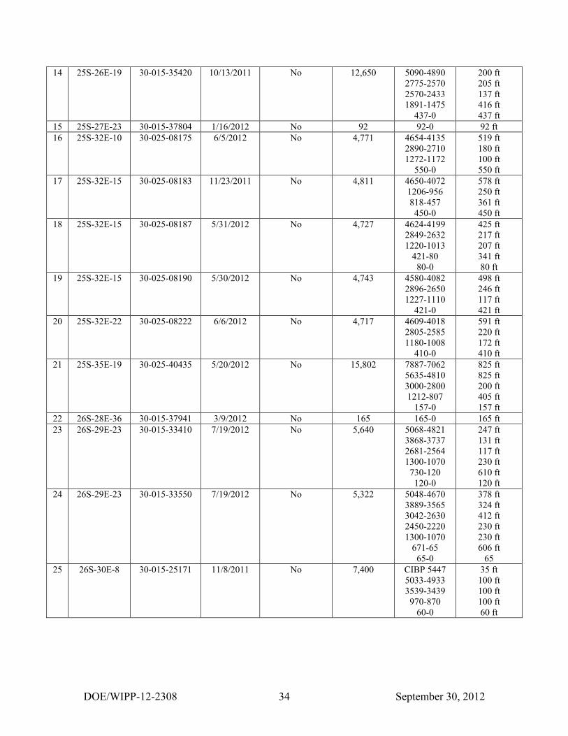
Table 8: Plugged Well Information # Location API# Plug Date R-111-P Area Well Depth Plug Depth Plug Length
1 22S-28E-31 30-015-24773 2/17/2012 No 3,650 3385-3350
3200-3165
2400-0
35 ft
35 ft
2400 ft
2 22S-31E-6 30-015-21098 12/26/2011 Yes 14,050 CIBP 5848
3750-0
35 ft
3750 ft
3 23S-28E-9 30-015-23525 1/31/2012 No 12,852 12220-11198
10294-9772
9678-9434
9157-8950
6167-5967
4394-2618
1035-850
495-0
1022 ft
522 ft
244 ft
207 ft
200 ft
1776 ft
185 ft
495 ft
4 23S-28E-9 30-015-23759 3/12/2012 No 4,300 3600-3460
2600-2470
1030-920
490-0
140 ft
130 ft
110 ft
490 ft
5 23S-31E-9 30-015-26509 5/21/2012 Yes 15,175 CIBP 5000
4168-0
35 ft
4168 ft
6 23S-31E-12 30-015-30063 4/4/2012 No 8,450 5280-5122
4584-4140
1161-785
60-0
158 ft
444 ft
376 ft
60 ft
7 23S-31E-14 30-015-32866 12/14/2011 Yes 8,500 6950-6780
6100-5940
4500-818
135-0
170 ft
160 ft
3682 ft
135 ft
8 23S-34E-30 30-025-08489 4/4/2012 No 13,044 5653-4842
4041-3938
1319-1151
195-0
811 ft
103 ft
168 ft
195 ft
9 24S-31E-7 30-015-03699 9/27/2011 No 2,791 2778-2395
1050-920
350-0
383 ft
130 ft
350 ft
10 24S-31E-8 30-015-27228 4/24/2012 No 8,208 7882-7635
6083-5831
4223-3727
882-0
247 ft
252 ft
496 ft
882 ft
11 24S-31E-11 30-015-10259 9/20/2011 No 6,500 5480-5080
5040-914
465-0
400 ft
4126 ft
465 ft
12 25S-25E-1 30-015-21023 10/19/2011 No 11,850 3270-3169
1720-1305
407-0
101 ft
415 ft
407 ft
13 25S-26E-6 30-015-34523 4/22/2012 No 12,167 10435-10195
8510-8110
7407-7081
5355-5040
2622-2422
1825-1591
1575-1265
268-0
240 ft
400 ft
326 ft
315 ft
200 ft
234 ft
310 ft
268 ft
DOE/WIPP-12-2308 September 30, 2012 34
14 25S-26E-19 30-015-35420 10/13/2011 No 12,650 5090-4890
2775-2570
2570-2433
1891-1475
437-0
200 ft
205 ft
137 ft
416 ft
437 ft
15 25S-27E-23 30-015-37804 1/16/2012 No 92 92-0 92 ft
16 25S-32E-10 30-025-08175 6/5/2012 No 4,771 4654-4135
2890-2710
1272-1172
550-0
519 ft
180 ft
100 ft
550 ft
17 25S-32E-15 30-025-08183 11/23/2011 No 4,811 4650-4072
1206-956
818-457
450-0
578 ft
250 ft
361 ft
450 ft
18 25S-32E-15 30-025-08187 5/31/2012 No 4,727 4624-4199
2849-2632
1220-1013
421-80
80-0
425 ft
217 ft
207 ft
341 ft
80 ft
19 25S-32E-15 30-025-08190 5/30/2012 No 4,743 4580-4082
2896-2650
1227-1110
421-0
498 ft
246 ft
117 ft
421 ft
20 25S-32E-22 30-025-08222 6/6/2012 No 4,717 4609-4018
2805-2585
1180-1008
410-0
591 ft
220 ft
172 ft
410 ft
21 25S-35E-19 30-025-40435 5/20/2012 No 15,802 7887-7062
5635-4810
3000-2800
1212-807
157-0
825 ft
825 ft
200 ft
405 ft
157 ft
22 26S-28E-36 30-015-37941 3/9/2012 No 165 165-0 165 ft
23 26S-29E-23 30-015-33410 7/19/2012 No 5,640 5068-4821
3868-3737
2681-2564
1300-1070
730-120
120-0
247 ft
131 ft
117 ft
230 ft
610 ft
120 ft
24 26S-29E-23 30-015-33550 7/19/2012 No 5,322 5048-4670
3889-3565
3042-2630
2450-2220
1300-1070
671-65
65-0
378 ft
324 ft
412 ft
230 ft
230 ft
606 ft
65
25 26S-30E-8 30-015-25171 11/8/2011 No 7,400 CIBP 5447
5033-4933
3539-3439
970-870
60-0
35 ft
100 ft
100 ft
100 ft
60 ft

DOE/WIPP-12-2308 September 30, 2012 35
Table 9: Past Plugging Summary by Well Type
Type CCA
Well Count
CCA
Frequency
CRA-2004
Well Count
CRA-2004
Frequency
CRA-2009
Well Count
CRA-2009
Frequency
I 61 32.5% 116 34.1% 131 30.5%
II 37 20% 60 17.7% 84 19.5%
III 64 34% 111 32.6% 142 33%
IV 19 10% 38 11.2% 52 12.1%
V 3 1.5% 10 2.9% 13 3%
VI 4 2% 5 1.5% 8 1.9%
TOTALS 188 100% 340 100% 430 100%
Table 10: Current Plugging Summary by Well Type for the CRA-2014
Type CRA-
2009
CRA-2009
Frequency 2008 2009 2010 2011 2012 Total
Current
Frequency Change
I 131 30.5% 1 6 2 3 4 147 26.9% -3.6%
II 84 19.5% 5 6 12 3 0 110 20.1% +0.6%
III 142 33.0% 4 1 9 5 2 163 29.9% -3.1%
IV 52 12.1% 4 4 14 4 12 90 16.5% +4.4%
V 13 3.0% 0 1 0 0 0 14 2.6% -0.4%
VI 8 1.9% 2 1 1 5 5 22 4.0% +2.1%
TOTALS 430 100.0% 16 19 38 20 23 546 100.0%
NOTE: The 1996 Compliance Certification Application (CCA) used the 188 wells categorized into the
above classifications to arrive at the percentage or frequency of each plugging event. The
Compliance Recertification Application (CRA) followed up on that study and 152 wells were
added to the original number to update the frequency. In 2003, 23 wells were plugged and
abandoned in the New Mexico portion of the Delaware Basin. Three were ruled out because they
were less than 2,150 feet deep. Twenty wells were categorized into one of the above plugging
configurations and added to the count. For 2004, 25 wells were plugged and abandoned and were
added to the count. In 2005, 24 wells were plugged and abandoned but only 20 wells were used
since two wells were shallow and two did not have any plugging reports available at the time of
this report. For 2006, 10 wells were plugged and abandoned in the New Mexico portion of the
Delaware Basin and were added to the count. In 2007, 16 wells were plugged, with one being
shallow. Thus, 15 wells were added to the above count. The change indicated above is between
the current and the CRA frequencies for each type of plugging configuration.

DOE/WIPP-12-2308 September 30, 2012 36
Table 11: Seismic Activity in the Delaware Basin County No. of Events Earliest Event Latest Event Smallest Magnitude Largest Magnitude
Culberson 15 10/27/1992 6/28/2007 1.1 2.4
Eddy 19 11/28/1975 3/18/2012 -1.3 3.7
Lea 1 6/23/1993 6/23/1993 2.1 2.1
Loving 3 2/4/1976 4/28/1997 1.1 1.6
Pecos 19 1/30/1975 3/10/2010 1.0 2.6
Reeves 19 2/19/1976 3/2/2012 0.6 2.4
Ward 50 9/3/1976 7/1/2009 0.3 2.8
Winkler 9 9/24/1971 10/19/2007 0.0 3.0
TOTAL 135
KEY:
Magnitude
Less than 2 Very seldom ever felt
2.0 to 3.4 Barely felt
3.5 to 4.2 Felt as a rumble
4.3 to 4.9 Shakes furniture; can break dishes
5.0 to 5.9 Dislodges heavy objects; cracks walls
6.0 to 6.9 Considerable damage to buildings
7.0 to 7.3 Major damage to buildings; breaks underground pipes
7.4 to 7.9 Great damage; destroys masonry and frame buildings
Above 8.0 Complete destruction; ground moves in waves
NOTE: Four of the nineteen seismic events in Eddy County can be directly attributed to mining activities.

DOE/WIPP-12-2308 September 30, 2012 37
Table 12: Nine-Township Injection and SWD Well Information # Location API# Status Injection Zone First Injection Last Injection Cumulative Bbl
1 21S-31E-33 30-015-29330 SWD 4,166-5,160 1998 June 2012 5,658,096
2 21S-32E-08 30-025-31412 SWD 4,826-5,978 1991 June 2012 14,018,079
3 21S-32E-31 30-025-31443 SWD 4,618-6,012 1992 June 2012 377,786
4 22S-30E-02 30-015-25758 Injection 7,200-7,264 1993 June 2012 21,673,409
5 22S-30E-02 30-015-26761 Injection 5,600-7,400 1991 June 2012 22,320,755
6 22S-30E-25 30-015-33439 SWD 5,678-7,682 2010 June 2012 981,521
7 22S-30E-27 30-015-04734 SWD 3,820-3,915 1981 June 2012 5,476,714
8 22S-31E-02 30-015-32440 Injection 6,989-7,020 2003 June 2012 2,412,936
9 22S-31E-24 30-015-26848 SWD 4,519-5,110 1991 June 2012 11,764,462
10 22S-31E-25 30-015-28281 Injection 7,050-7,068 1995 June 2012 11,511,739
11 22S-31E-35 30-015-26629 SWD 4,500-5,670 1991 June 2012 22,272,839
12 22S-31E-36 30-015-26171 SWD 4,500-5,700 1998 June 2012 213,867
13 22S-32E-05 30-025-27620 SWD 5,150-8,602 2004 June 2012 6,616,121
14 22S-32E-06 30-025-31227 SWD 4,626-5,730 2012 June 2012 554,593
15 22S-32E-07 30-025-31076 SWD 4,676-5,814 1991 June 2012 12,407,852
16 22S-32E-11 30-025-31716 SWD 5,200-8,706 1994 June 2012 2,859,021
17 22S-32E-14 30-025-08113 SWD 4,900-6,080 1994 June 2012 5,873,807
18 22S-32E-16 30-025-31644 SWD 5,582-6,380 2010 June 2012 666,975
19 22S-32E-16 30-025-31889 SWD 5,240-8,710 1995 June 2012 11,759,115
20 22S-32E-16 30-025-36006 SWD 5,858-6,450 2010 June 2012 1,226,217
21 22S-32E-17 30-025-31926 SWD 6,807-6,828 2007 June 2012 2,380,163
22 22S-32E-21 30-025-08109 SWD 4,755-5,110 1992 June 2012 3,721,392
23 22S-32E-27 30-025-32436 Injection 6,831-8,388 1998 June 2012 8,582,373
24 22S-32E-28 30-025-31754 SWD 4,690-5,800 1993 June 2012 4,971,618
25 22S-32E-31 30-025-20423 SWD 4,662-5,915 1993 June 2012 5,316,095
26 22S-32E-31 30-025-32093 SWD 4,590-5,626 2004 June 2012 850,875
27 22S-32E-32 30-025-36004 SWD 6,744-8,518 2010 June 2012 1,961,390
28 22S-32E-32 30-025-37799 SWD 5,754-6,500 2010 June 2012 1,634,550
29 22S-32E-35 30-025-33149 SWD 4,950-6,252 1995 June 2012 7,739,418
30 23S-30E-01 30-015-21052 SWD 4,040-4,825 2001 June 2012 3,354,398
31 23S-30E-16 30-015-20899 SWD 4,433-5,952 2003 June 2012 2,037,521

DOE/WIPP-12-2308 September 30, 2012 38
32 23S-30E-19 30-015-28901 SWD 3,402-4,609 1997 June 2012 3,451,241
33 23S-30E-20 30-015-29549 SWD 4,124-4,774 2006 June 2012 2,113,613
34 23S-30E-29 30-015-28808 SWD 5,479-7,220 1996 June 2012 4,266,779
35 23S-30E-33 30-015-26084 SWD 4,470-7,558 2005 June 2012 5,571,379
36 23S-30E-33 30-015-31744 SWD 4,546-6,760 2002 June 2012 5,476,329
37 23S-31E-02 30-015-05840 SWD 4,489-5,670 1997 June 2012 9,074,916
38 23S-31E-02 30-015-29792 SWD 4,500-5,850 1998 June 2012 9,600,298
39 23S-31E-02 30-015-35749 SWD 4,600-5,880 2010 July 2012 996,247
40 23S-31E-08 30-015-32619 SWD 7,256-7,530 2004 June 2012 2,270,374
41 23S-31E-09 30-015-33368 SWD 7,942-7,952 2005 June 2012 3,955,016
42 23S-31E-11 30-015-25419 SWD 5,210-5,800 2005 June 2012 1,095,536
43 23S-31E-13 30-015-28904 SWD 5,760-5,862 2005 June 2012 893,513
44 23S-31E-20 30-015-30605 Injection 7,740-7,774 2001 June 2012 6,766,328
45 23S-31E-25 30-015-28817 SWD 5,776-5,920 2008 June 2012 337,919
46 23S-31E-25 30-015-28859 SWD 5,236-5,498 2008 June 2012 861,645
47 23S-31E-26 30-015-20277 SWD 4,460-5,134 1992 June 2012 4,873,042
48 23S-31E-26 30-015-20302 SWD 4,390-6,048 1971 June 2012 6,903,358
49 23S-31E-27 30-015-27106 SWD 4,694-5,284 1998 June 2012 5,925,469
50 23S-31E-28 30-015-26194 SWD 4,295-5,570 1993 June 2012 6,207,664
51 23S-31E-35 30-015-25640 SWD 4,484-5,780 1993 June 2012 7,593,595
52 23S-31E-36 30-015-20341 SWD 5,980-6,560 1994 June 2012 24,817,485
53 23S-32E-04 30-025-31650 SWD 4,884-5,886 2003 June 2012 4,202,003
54 23S-32E-07 30-025-33398 SWD 4,660-6,270 2009 June 2012 959,116
55 23S-32E-14 30-025-26844 SWD 5,496-6,014 1991 June 2012 1,935,010
56 23S-32E-15 30-025-35524 SWD 5,786-5,942 2008 June 2012 255,471
57 23S-32E-23 30-025-33653 SWD 5,954-6,064 2000 June 2012 1,632,798
58 23S-32E-24 30-025-33521 SWD 5,925-6,042 2001 June 2012 1,832,719
59 23S-32E-29 30-025-31515 SWD 4,844-4,944 1992 July 2012 10,997,400
60 23S-32E-31 30-025-32868 SWD 5,150-5,700 1996 June 2012 3,272,416
61 23S-32E-36 30-025-31929 SWD 5,364-6,138 1995 June 2012 4,016,484
NOTE: Information collected from New Mexico Oil Conservation Division (OCD) offices in Artesia and
Hobbs, New Mexico. Also, cumulative barrels information is collected from the Internet site
maintained by the New Mexico Institute of Mining and Technology on behalf of the New Mexico
OCD (NMIMT).

DOE/WIPP-12-2308 September 30, 2012 39
Table 13: Brine Well Status in the Delaware Basin County Location API# Well Name and No. Operator Status
Eddy 22S-26E-36 30-015-21842 City Of Carlsbad #WS-1 Key Energy Services, LLC Plugged Brine Well
Eddy 22S-27E-03 30-015-20331 Tracy #3 Ray Westall Plugged Brine Well
Eddy 22S-27E-17 30-015-22574 Eugenie #WS-1 I & W Inc. Plugged Brine Well
Eddy 22S-27E-17 30-015-23031 Eugenie #WS-2 I & W Inc. Plugged Brine Well
Eddy 22S-27E-23 30-015-28083 Dunaway #1 Mesquite SWD, Inc. Active Brine Well
Eddy 22S-27E-23 30-015-28084 Dunaway #2 Mesquite SWD, Inc. Active Brine Well
Loving Blk 29-03 42-301-10142 Lineberry Brine Station #1 Chance Properties Company Active Brine Well
Loving Blk 01-82 42-301-30680 Chapman Ford #BR1 Herricks & Son Co. Plugged Brine Well
Loving Blk 33-80 42-301-80318 Mentone Brine Station #1D Basic Energy Services, LP Active Brine Well
Loving Blk 29-28 42-301-80319 East Mentone Brine Station #1 Permian Brine Sales, Inc. Plugged Brine Well
Loving Blk 01-83 42-301-80320 North Mentone #1 Chance Properties Company Active Brine Well
Reeves Blk 56-30 42-389-00408 Orla Brine Station #1D Mesquite SWD, Inc. Active Brine Well
Reeves Blk 04-08 42-389-20100 North Pecos Brine Station #WD-1 Chance Properties Company Active Brine Well
Reeves Blk 07-21 42-389-80476 Coyanosa Brine Station #1 Chance Properties Company Active Brine Well
Ward Blk 17-20 42-475-31742 Pyote Brine Station #WD-1 Chance Properties Company Active Brine Well
Ward Blk 01-13 42-475-34514 Quito West Unit #207 Seaboard Oil Co. Active Brine Well
Ward Blk 34-200 42-475-20329 Barstow Brine Station #1 Basic Energy Services, LP Active Brine Well
Ward Blk 34-174 42-475-82265 Barstow Brine Station #1 Energy Equity Company Active Brine Well