Embed Size (px)
Citation preview
Deliverable D3.3 CPaaS.io System Architecture (v2)
H2020 EUJ-02-2016 CPaaS.io Page 1 of 84
H2020-EUJ-02-2016
H2020 Grant Agreement Number 723076 NICT Management Number 18302
Deliverable D3.3
CPaaS.io System Architecture (v2)
Version V2.0
September 30th, 2017
ABSTRACT
This third WP3 deliverable provides an update of the initial CPaaS.io architecture D3.2. The architecture work follows the requirement collection phase (as already summarised in Deliverable D3.1) and improves the previous version of the architecture, capturing the work achieved by other technical Work Packages since D3.2 was released. This document provides some elements of the used methodology and then provides both the updated Functional and Information Views, together with some Perspectives (including security and interoperability in particular). The Functional View gives a second view about which functional components need to be implemented in order to fulfil functional requirements. Perspectives on the other hand focuses on how (through strategies and tactics) the non-functional requirements can be fulfilled.
As explained in the DoW, we are using the IoT ARM methodology, which means that this document features a technology-agnostic logical architecture - which is agreed upon by both parties (Japan and EU) - in addition to two concrete instantiations of this logical architecture (later referred as u2-based and FIWARE-based concrete architectures) which are formally captured within two so-called Instantiation Views.
Finally an accompanying technical annex in the form of a Volere template, keeps track of the functional and non-functional requirement coverage, through respectively the architecture Views and Perspectives. This template is the result of the requirement process, part of the IoT ARM methodology.
This work is licensed under the Creative Commons Attribution 4.0 International License. To view a copy of this license, visit http://creativecommons.org/licenses/by/4.0/.
Deliverable D3.3 CPaaS.io System Architecture (v2)
H2020 EUJ-02-2016 CPaaS.io Page 2 of 84
Disclaimer
This document has been produced in the context of the CPaaS.io project which is jointly funded by the European Commission (grant agreement n° 723076) and NICT from Japan (management number 18302). All information provided in this document is provided "as is" and no guarantee or warranty is given that the information is fit for any particular purpose. The user thereof uses the information at its sole risk and liability. For the avoidance of all doubts, the European Commission and NICT have no liability in respect of this document, which is merely representing the view of the project consortium. This document is subject to change without notice.
Document Information
Editor François Carrez (UoS) Authors Editor +
A. Skarmeta, J-A. Martinez, M-A. Zamora, A. Canovas (OdinS); M. Strohbach (AGT), S. Haller, M. Fraefel, A. Gschwend (BFH); G. Solmaz, B. Cheng, M. Bauer (NEC); N. Koshizuka (UoT) K. Shindo (YRP)
Reviewers Stephan Haller (BFH); Katsunori Shindo (YRP)
Delivery Type R Dissemination Level
Public
Contractual Delivery Date
September 30th, 2017
Actual Delivery Date
September 30th, 2017
Keywords Requirement analysis, functional decomposition, system use-cases, system architecture, concrete platform instantiations, IoT ARM
Deliverable D3.3 CPaaS.io System Architecture (v2)
H2020 EUJ-02-2016 CPaaS.io Page 3 of 84
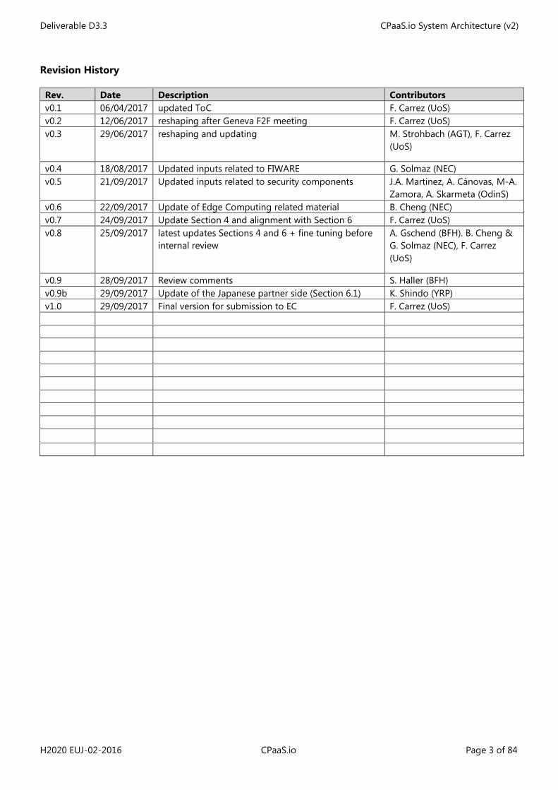
Revision History
Rev. Date Description Contributors v0.1 06/04/2017 updated ToC F. Carrez (UoS) v0.2 12/06/2017 reshaping after Geneva F2F meeting F. Carrez (UoS) v0.3 29/06/2017 reshaping and updating M. Strohbach (AGT), F. Carrez
(UoS)
v0.4 18/08/2017 Updated inputs related to FIWARE G. Solmaz (NEC) v0.5 21/09/2017 Updated inputs related to security components J.A. Martinez, A. Cánovas, M-A.
Zamora, A. Skarmeta (OdinS) v0.6 22/09/2017 Update of Edge Computing related material B. Cheng (NEC) v0.7 24/09/2017 Update Section 4 and alignment with Section 6 F. Carrez (UoS) v0.8 25/09/2017 latest updates Sections 4 and 6 + fine tuning before
internal review A. Gschend (BFH). B. Cheng & G. Solmaz (NEC), F. Carrez (UoS)
v0.9 28/09/2017 Review comments S. Haller (BFH) v0.9b 29/09/2017 Update of the Japanese partner side (Section 6.1) K. Shindo (YRP) v1.0 29/09/2017 Final version for submission to EC F. Carrez (UoS)
Deliverable D3.3 CPaaS.io System Architecture (v2)
H2020 EUJ-02-2016 CPaaS.io Page 4 of 84
Table of Contents
1 Introduction ................................................................................................................................................................................ 8
1.1 Delta with previous version D3.2 ................................................................................................................................ 9
2 Methodology ............................................................................................................................................................................ 10
2.1 Introduction to the IoT ARM ...................................................................................................................................... 10
2.2 Using the IoT ARM in the context of CPaaS.io .................................................................................................... 20
3 CPaaS.io Requirements Analysis and Mapping ........................................................................................................... 20
3.1 Summary of requirement collection phase ........................................................................................................... 20
3.2 Requirement Analysis .................................................................................................................................................... 29
4 CPaaS.io Views ......................................................................................................................................................................... 30
4.1 Actors involved in data production.......................................................................................................................... 30
4.2 CPaaS.io Functional View ............................................................................................................................................. 31
4.3 CPaaS.io Information View .......................................................................................................................................... 40
5 Perspectives............................................................................................................................................................................... 50
5.1 Security ............................................................................................................................................................................... 50
5.2 Semantic Interoperability ............................................................................................................................................. 52
5.3 Performance ...................................................................................................................................................................... 52
5.4 Scalability ........................................................................................................................................................................... 53
6 Instantiation views .................................................................................................................................................................. 53
6.1 U2-based platform Instantiation View .................................................................................................................... 53
6.2 FIWARE-based platform Instantiation View .......................................................................................................... 62
7 Conclusions & Next Steps ................................................................................................................................................... 82
8 References ................................................................................................................................................................................. 83
Deliverable D3.3 CPaaS.io System Architecture (v2)
H2020 EUJ-02-2016 CPaaS.io Page 5 of 84
List of Figures
Figure 1: Simplified process leading to generating a concrete architecture ........................................................... 10 Figure 2: Simplified IoT Domain Model (feat. most important concepts) ................................................................ 11 Figure 3: IoT Domain Model (as in IoT-A D1.5 [1]) ............................................................................................................ 13 Figure 4: IoT Information Model (as in IoT-A D1.5 [1]) .................................................................................................... 14 Figure 5: IoT Functional Model (as in IoT-A D1.5 [1]) ....................................................................................................... 16 Figure 6: IoT Functional View (as in IoT-A D1.5 [1]) .......................................................................................................... 17 Figure 7: CPaaS.io logical functional architecture .............................................................................................................. 32 Figure 8: UML UC for Class-I RDP pre-configuration case ............................................................................................. 42 Figure 9: UML UC for Class-II RDP pre-configuration case ............................................................................................ 43 Figure 10: UML UC for Class-III RDP pre-configuration phase ..................................................................................... 44 Figure 11: Data production for Class-I RDPs........................................................................................................................ 46 Figure 12: Data production for Class-II RDP ........................................................................................................................ 47 Figure 13: u2 Architecture (ucR focus) ................................................................................................................................... 55 Figure 14: u2 architecture (IoT Aggregator focus) ............................................................................................................. 56 Figure 15: u2 architecture ("Omotenashi" Cloud focus) .................................................................................................. 57 Figure 16: IoT Engine with IoT Engine Open Platform ..................................................................................................... 58 Figure 17: uID architecture ......................................................................................................................................................... 59 Figure 18: Matching of the u2 components to the CPaaS.io Functional View ........................................................ 60 Figure 19: FogFlow Service Orchestrator ............................................................................................................................... 66 Figure 20: Task Registration ....................................................................................................................................................... 67 Figure 21: Graphical editor of service topology ................................................................................................................. 68 Figure 22: Defining a requirement with a specified geo-scope .................................................................................... 68 Figure 23: FIWARE-based CPaaS.io architecture ................................................................................................................ 72 Figure 24: Matching of the FIWARE components to the CPaaS.io Functional View ............................................. 74 Figure 25: Interactions of the FIWARE FCs............................................................................................................................ 75 Figure 26. PAP Web configuration interface ........................................................................................................................ 79
List of Tables
Table 1: List of Non-Functional Requirements .................................................................................................................... 25 Table 2: List of Functional Requirements .............................................................................................................................. 27
Deliverable D3.3 CPaaS.io System Architecture (v2)
H2020 EUJ-02-2016 CPaaS.io Page 6 of 84
List of Acronyms
Acronym Definition ABE Attribute Based Encryption ACP Access Control Policy AE Augmented Entity API Application Programming Interface AuthN AuthenticatioN AuthZ AuthoriZation BC Business Case IoT ARM IoT Architectural Reference Model CapBAC capability-based access control model CEP Complex Event Processing CP-ABE Ciphertext-Policy Attribute-Base Encryption CPU Central Process Unit CRM Customer Relationship Management CSF Common Service Function CSV Comma Separated Values CT Capability Token DC Design Constraints DoW Description of Work FC Functional Component FG Functional Group FREQ Functional REQuirement FV Functional View GDLI Governement Data Listener & Ingestion GE General Enabler GUI Graphical User Interface HFDS Highly Functionally Distributed System HSM Hardware Security Module IdM Identity Management IoT Internet of Things IoT-A Internet of Things – Architecture JSON JavaScript Object Notation KAT Knowledge Acquisition Toolkit IdM Identity Management IV Information View LDLI Live Data Listener & Ingestion LOD Linked Open Data M2M Machine to Machine MPU Micro Processor Unit NFREQ Non Functional REQuirement NGO Non-Governmental Organisation NGSI Next Generation Service Interface OMA Open Mobile Alliance OMG Object Management Group PAP Policy Administration Point PDP Policy Decision Point PDS Personal Data Store PEP Policy Enforcement Point PE Physical Entity PKC Public Key Cryptography
Deliverable D3.3 CPaaS.io System Architecture (v2)
H2020 EUJ-02-2016 CPaaS.io Page 7 of 84
Acronym Definition PKI Public Key Infrastructure RDF Resource Description Framework RDFS RDF Schema RDP Raw Data Producer (or Provider) RTOS Real-Time Operating System SCIM System for Cross-domain Identity Management SCP (ETSI) Smart Card Platform SKC Symmetric Key Cryptography SotA State of the Art SPARQL SPARQL Protocol and RDF Query Language SSN Semantic Sensor Network UC Use-Case VE Virtual Entity VRM Vendor Relationship Management XACML eXtensible Access Control Markup Language
List of Editing Shortcuts
Shortcut Definition e.g. exempli gratia – for example etc et cetera feat. featuring Gov Government h/w hardware i.e. id est – that is incl. including p/f platform resp. respectively s/w software tbd to be discussed/decided vs. versus w.r.t. with respect to
Deliverable D3.3 CPaaS.io System Architecture (v2)
H2020 EUJ-02-2016 CPaaS.io Page 8 of 84
1 Introduction
This Deliverable D3.3 is the second version of the incremental architecture document that was initiated with D3.2. It will be completed and improved within two additional versions, D3.5 and D3.7 respectively due M25 and M30.
Leveraging on D3.2, this version goes deeper in the CPaaS.io architecture, introducing more components and more detail (see the following sub-section that goes in the detail of the delta between D3.3 and D3.5).
In the CPaaS.io project, we are reusing the architectural approach promoted by the IoT-A FP7 project called the Internet of Things Architectural Reference Model (IoT ARM). As we explain in Section 2, the IoT ARM is not an IoT architecture as such; instead it provides a whole methodology and framework for creating such an IoT Architecture.
While an architecture team usually uses the IoT ARM for creating one single concrete architecture considering one single use case (targeted product), CPaaS.io has to face an additional difficulty as the project will produce two different concrete platform architectures: one for the Japanese side, based on u2 technology and a second one for the European side based on FIWARE. The IoT ARM is therefore a tool that helps the two involved communities for reaching common understanding and agreeing on the main architecture principles. The scope of this agreement includes:
• A taxonomy of concepts (Domain Model); • A logical structure for dealing with information (Information Model); • A functional decomposition into logical components (Functional View); • System use-cases that illustrate interactions taking place between functional components for
some typical platform usage (Information View); • A strategy for ensuring interoperability, since the two concrete instantiations of a common
“abstract & logical” platform architecture must eventually talk with each other and understand each other in order to implement the interoperability and federation principles described as one of the main technical objectives of the CPaaS.io project;
• Strategies for ensuring additional system qualities (Perspectives).
The two later aspects – fully developed in the second iteration of the architecture- are usually dealt with, with the adoption of common or compatible design and technology choices (e.g. adopting RDF as a semantic data internal format and JSON-LD for serialisation) and the definition of common interfaces (e.g. adopting REST, SPARQL etc.).
Finally this document is accompanied with a technical annex (Volere MicroSoft Excel document) that summarises the functional and non-functional requirements resulting from earlier project activities (see D2.1 [2] and D3.1 [4] for more detail about Requirement collection and analysis).
This deliverable is then structured as follows.
Section 2 gives an introduction to the IoT ARM and in particular details the process part of the IoT ARM methodology, focussing on requirement engineering, views and perspective definition.
Deliverable D3.3 CPaaS.io System Architecture (v2)
H2020 EUJ-02-2016 CPaaS.io Page 9 of 84
Section 3 focuses on requirements and provides some insights about the analysis of requirements collected earlier form the scenario holders on the one hand and on the other hand on functional/non-functional requirements as seen from the platform perspective. It also shows the current coverage of the set of requirements by the functional decomposition discussed in Section 4.2.
Section 4 provides the revised views of the CPaaS.io architecture. The functional view depicts and describes a preliminary functional decomposition following the IoT ARM layered Functional Model, while the Information View, at this stage, mainly consists of a collection of system use-cases that describe inter-FCs interactions for a selected set of basic activities at platform level, involving not only the platform, but additional actors like platform clients and data producers as well.
Section 5 consists of the architecture Perspectives and gives insights about how the different non-functional properties of the system are dealt with.
Section 6 is an important section that bridges the common logical and abstract view upon the CPaaS.io architecture to two distinct – still compatible- instantiations of it. It describes in particular the various reused components (u2- and FIWARE- based technologies) and spots some new ones, which will be in the centre of CPaaS.io specific software developments. It also shows how the concrete sets of components maps to the abstract and logical functional decomposition.
Finally Section 7 provides a conclusion and in particular gives some hints about the few limitations and gaps of this preliminary version. It also details next steps towards CPaaS.io architecture v3.
1.1 Delta with previous version D3.2
Deliverables describing the CPaaS.io architecture, namely D3.2, D3.3, D3.5 and D3.7, are incremental documents. This section aims at describing updates brought since the previous version:
• Section 4.1.1: Updated classification of RDPs; • Section 4.2: The list of functional components (and their descriptions) has been updated. The
Functional Architecture figure has been aligned to this updated list; Change in the classification of Raw Data Producers;
• Section 4.3.1: Revised and updated system Use Cases (aligned with their instantiated counterparts in section 6);
• Section 4.3.2: Short overview of foreseen usage for CPaaS.io ontologies; • Section 6.x.1, 6.x.2: Update to the two U2- & FIWARE- based platform instantiation views (more
FCs, adjustment, FC interfaces & functionalities); • Section 6.x.3: revised mapping tables; • Section 6.x.4: new sections with few useful and typical concrete system Use Cases (to be extended
in following versions).
The general idea of having System Use Cases described in this document is two-fold:
• Having a common understanding on how the platform behaves (meaning how FCs interacts with each other) at both logical and concrete levels (that’s why system UCs appears in two different sections, respectively section 4.2 and 6);
• Proposing to CPaaS.io users, a catalogue of usage patterns (or reference implementations) that can be referred to when implementing new scenarios.
UCs consist of UML use cases and sequence diagrams.
Deliverable D3.3 CPaaS.io System Architecture (v2)
H2020 EUJ-02-2016 CPaaS.io Page 10 of 84
2 Methodology
2.1 Introduction to the IoT ARM
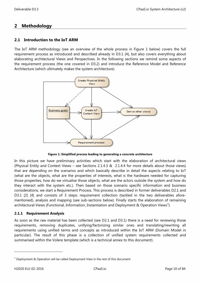
The IoT ARM methodology (see an overview of the whole process in Figure 1 below) covers the full requirement process as introduced and described already in D3.1 [4], but also covers everything about elaborating architectural Views and Perspectives. In the following sections we remind some aspects of the requirement process (the one covered in D3.2) and introduce the Reference Model and Reference Architecture (which ultimately makes the system architecture).
Figure 1: Simplified process leading to generating a concrete architecture
In this picture we have preliminary activities which start with the elaboration of architectural views (Physical Entity and Context Views – see Sections 2.1.4.3 & 2.1.4.4 for more details about those views) that are depending on the scenarios and which basically describe in detail the aspects relating to IoT (what are the objects, what are the properties of interests, what is the hardware needed for capturing those properties, how do we virtualise those objects, what are the actors outside the system and how do they interact with the system etc.). Then based on those scenario specific information and business considerations, we start a Requirement Process. This process is described in former deliverables D2.1 and D3.1 [2] [4] and consists of 3 steps: requirement collection (tackled in the two deliverables afore-mentioned), analysis and mapping (see sub-sections below). Finally starts the elaboration of remaining architectural Views (Functional, Information, Instantiation and Deployment & Operation Views1).
2.1.1 Requirement Analysis
As soon as the raw material has been collected (see D2.1 and D3.1) there is a need for reviewing those requirements, removing duplicates, unifying/factorizing similar ones and translating/rewriting all requirements using unified terms and concepts as introduced within the IoT ARM (Domain Model in particular). The result of this phase is a collection of unified system requirements collected and summarised within the Volere template (which is a technical annex to this document).
1 Deployment & Operation will be called Deployment View in the rest of this document
Deliverable D3.3 CPaaS.io System Architecture (v2)
H2020 EUJ-02-2016 CPaaS.io Page 11 of 84
2.1.2 Requirement Mapping
Functional unified requirements need to be mapped to the Functional View (FV) where one or more Functional Groups (FG) and Functional Components (FC) can be identified. This will result into a first functional decomposition of the targeted system. Some of the non-functional requirements can be mapped to the Information and Deployment Views. The CPaaS.io requirement analysis and mapping are covered in Section 3.
2.1.3 IoT Reference Model
In the IoT ARM methodology, the IoT Reference Model (RM) consists of a set of models which are used to describe aspects of the IoT field which are meant to be agreed upon by architecture team members. In the context of CPaaS.io we consider – for sake of simplicity – only three of them, namely the IoT Domain, Information and Functional Models.
2.1.3.1 IoT Domain Model
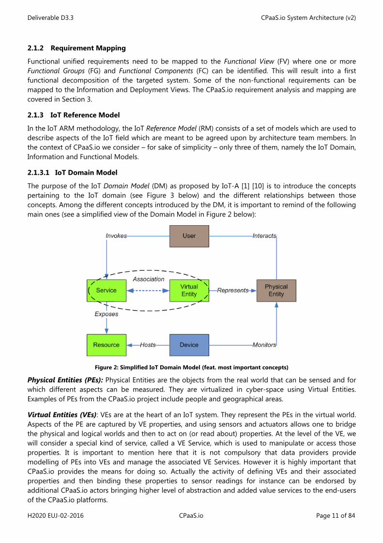
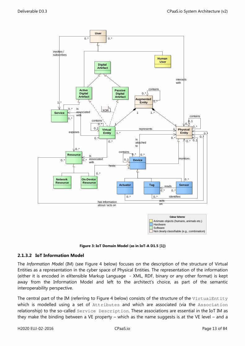
The purpose of the IoT Domain Model (DM) as proposed by IoT-A [1] [10] is to introduce the concepts pertaining to the IoT domain (see Figure 3 below) and the different relationships between those concepts. Among the different concepts introduced by the DM, it is important to remind of the following main ones (see a simplified view of the Domain Model in Figure 2 below):
Figure 2: Simplified IoT Domain Model (feat. most important concepts)
Physical Entities (PEs): Physical Entities are the objects from the real world that can be sensed and for which different aspects can be measured. They are virtualized in cyber-space using Virtual Entities. Examples of PEs from the CPaaS.io project include people and geographical areas.
Virtual Entities (VEs): VEs are at the heart of an IoT system. They represent the PEs in the virtual world. Aspects of the PE are captured by VE properties, and using sensors and actuators allows one to bridge the physical and logical worlds and then to act on (or read about) properties. At the level of the VE, we will consider a special kind of service, called a VE Service, which is used to manipulate or access those properties. It is important to mention here that it is not compulsory that data providers provide modelling of PEs into VEs and manage the associated VE Services. However it is highly important that CPaaS.io provides the means for doing so. Actually the activity of defining VEs and their associated properties and then binding these properties to sensor readings for instance can be endorsed by additional CPaaS.io actors bringing higher level of abstraction and added value services to the end-users of the CPaaS.io platforms.
Deliverable D3.3 CPaaS.io System Architecture (v2)
H2020 EUJ-02-2016 CPaaS.io Page 12 of 84
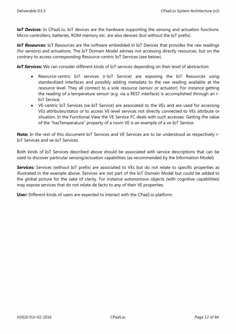
IoT Devices: In CPaaS.io, IoT devices are the hardware supporting the sensing and actuation functions. Micro-controllers, batteries, ROM memory etc. are also devices (but without the IoT prefix).
IoT Resources: IoT Resources are the software embedded in IoT Devices that provides the raw readings (for sensors) and actuations. The IoT Domain Model advises not accessing directly resources, but on the contrary to access corresponding Resource-centric IoT Services (see below).
IoT Services: We can consider different kinds of IoT services depending on their level of abstraction:
• Resource-centric IoT services (r-IoT Service) are exposing the IoT Resources using standardized interfaces and possibly adding metadata to the raw reading available at the resource level. They all connect to a sole resource (sensor or actuator). For instance getting the reading of a temperature sensor (e.g. via a REST interface) is accomplished through an r-IoT Service;
• VE-centric IoT Services (ve-IoT Service) are associated to the VEs and are used for accessing VEs attributes/status or to access VE-level services not directly connected to VEs attribute or situation. In the Functional View the VE Service FC deals with such accesses. Getting the value of the “hasTemperature” property of a room VE is an example of a ve-IoT Service.
Note: In the rest of this document IoT Services and VE Services are to be understood as respectively r-IoT Services and ve-IoT Services. Both kinds of IoT Services described above should be associated with service descriptions that can be used to discover particular sensing/actuation capabilities (as recommended by the Information Model).
Services: Services (without IoT prefix) are associated to VEs but do not relate to specific properties as illustrated in the example above. Services are not part of the IoT Domain Model but could be added to the global picture for the sake of clarity. For instance autonomous objects (with cognitive capabilities) may expose services that do not relate de facto to any of their VE properties.
User: Different kinds of users are expected to interact with the CPaaS.io platform.
Deliverable D3.3 CPaaS.io System Architecture (v2)
H2020 EUJ-02-2016 CPaaS.io Page 13 of 84
Figure 3: IoT Domain Model (as in IoT-A D1.5 [1])
2.1.3.2 IoT Information Model
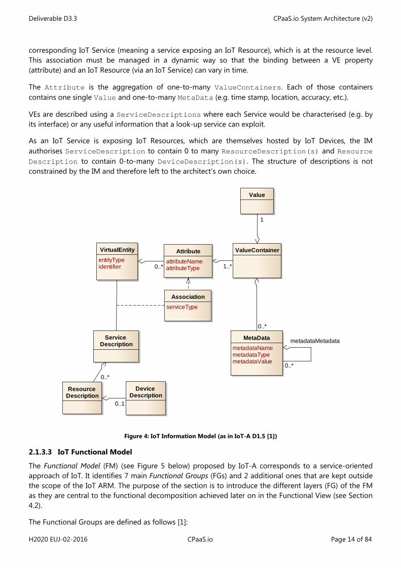
The Information Model (IM) (see Figure 4 below) focuses on the description of the structure of Virtual Entities as a representation in the cyber space of Physical Entities. The representation of the information (either it is encoded in eXtensible Markup Language - XML, RDF, binary or any other format) is kept away from the Information Model and left to the architect’s choice, as part of the semantic interoperability perspective.
The central part of the IM (referring to Figure 4 below) consists of the structure of the VirtualEntity which is modelled using a set of Attributes and which are associated (via the Association relationship) to the so-called Service Description. These associations are essential in the IoT IM as they make the binding between a VE property – which as the name suggests is at the VE level – and a
Device
Physical Entity
Human User
Service
On-Device Resource
SensorActuator
Network Resource
Resource
User
Passive Digital Artefact
Active Digital Artefact
Virtual Entity
Digital Artefact
Augmented Entity
Tag
Animate objects (humans, animals etc.)HardwareSoftwareNot clearly classifiable (e.g., combination)
Colour Scheme
XOR
0..*contains
0..11
1
0..*
invokes /subscribes
1..*
1..*represents 1
0..*
has Informationabout / acts on
0..*
0..*
isassociatedwith
0..*
0..*
contains0..*
0..* identifies
0..10..*
isassociatedwith
0..*
0..*contains
0..1
1
1..*
0..*
contains
0..10..*
exposes
0..*
0..*
interactswith
0..*
0..*
hosts1
0..*
isattachedto
0..*
0..*reads
0..*
0..*
monitors
0..*
0..*actson
0..*
Deliverable D3.3 CPaaS.io System Architecture (v2)
H2020 EUJ-02-2016 CPaaS.io Page 14 of 84
corresponding IoT Service (meaning a service exposing an IoT Resource), which is at the resource level. This association must be managed in a dynamic way so that the binding between a VE property (attribute) and an IoT Resource (via an IoT Service) can vary in time.
The Attribute is the aggregation of one-to-many ValueContainers. Each of those containers contains one single Value and one-to-many MetaData (e.g. time stamp, location, accuracy, etc.).
VEs are described using a ServiceDescriptions where each Service would be characterised (e.g. by its interface) or any useful information that a look-up service can exploit.
As an IoT Service is exposing IoT Resources, which are themselves hosted by IoT Devices, the IM authorises ServiceDescription to contain 0 to many ResourceDescription(s) and Resource Description to contain 0-to-many DeviceDescription(s). The structure of descriptions is not constrained by the IM and therefore left to the architect’s own choice.
Figure 4: IoT Information Model (as in IoT-A D1.5 [1])
2.1.3.3 IoT Functional Model
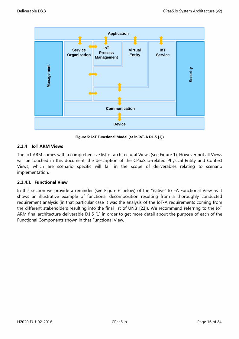
The Functional Model (FM) (see Figure 5 below) proposed by IoT-A corresponds to a service-oriented approach of IoT. It identifies 7 main Functional Groups (FGs) and 2 additional ones that are kept outside the scope of the IoT ARM. The purpose of the section is to introduce the different layers (FG) of the FM as they are central to the functional decomposition achieved later on in the Functional View (see Section 4.2).
The Functional Groups are defined as follows [1]:
AttributeattributeNameattributeType
MetaDatametadataNamemetadataTypemetadataValue
VirtualEntityentityTypeidentifier
Service Description
AssociationserviceType
Value
Device Description
Resource Description
ValueContainer
0..*
0..*
1
0..1
1..*
0..*
0..*
metadataMetadata
Deliverable D3.3 CPaaS.io System Architecture (v2)
H2020 EUJ-02-2016 CPaaS.io Page 15 of 84
• IoT Process Management FG: The purpose of this FG is to allow the integration of process management systems with the IoT platform. For example, the formal definition of a task-based application (supported by CPaaS.io platform) would fall into this category;
• Service Organisation FG: This FG is responsible for composing and orchestrating services, acting as a communication hub between other FGs. The execution of an application described within the IoT Process Management FG would take place in this FG, like any other kind of choreography/orchestration engine;
• Virtual Entity FG: This FG relates to VEs as defined in the IoT Domain model, and contains functionalities such as discovering VEs and their associations with IoT Services. This FG also allows access to the VE Service offered (formally “associated with”) by a Virtual Entity. In CPaaS.io those VE Services can be accessed via a VE endpoint;
• IoT Service FG: The IoT Service FG contains functions relating to Resource-centric IoT Services. Those services expose the resources like sensors and actuators and provide the means for reading sensor values or setting actuation. It also contains storage capability functionality. More specifically the IoT ARM states that: “A particular type of IoT Service can be the Resource history storage that provides storage capabilities for the measurements generated by resources”;
• Communication FG: The Communication FG is used to abstract the communication mechanisms used by the IoT Devices. Communication technologies used between applications and other FGs is out of scope for this FG as these are considered to be typical Internet technologies. A central message bus offering publish/subscribe functionalities would also be part of this FG as we will see when describing the CPaaS.io Functional View;
• Security FG: The Security “transversal” FG is responsible for ensuring the security and privacy of IoT- compliant systems. The management of security itself is also part of this FG;
• Management FG: The Management “transversal” FG contains components dealing with configuration, faults, reporting, membership and state. It should be mentioned here that this FG works in tight cooperation with the Security FG.
Deliverable D3.3 CPaaS.io System Architecture (v2)
H2020 EUJ-02-2016 CPaaS.io Page 16 of 84
Figure 5: IoT Functional Model (as in IoT-A D1.5 [1])
2.1.4 IoT ARM Views
The IoT ARM comes with a comprehensive list of architectural Views (see Figure 1). However not all Views will be touched in this document; the description of the CPaaS.io-related Physical Entity and Context Views, which are scenario specific will fall in the scope of deliverables relating to scenario implementation.
2.1.4.1 Functional View
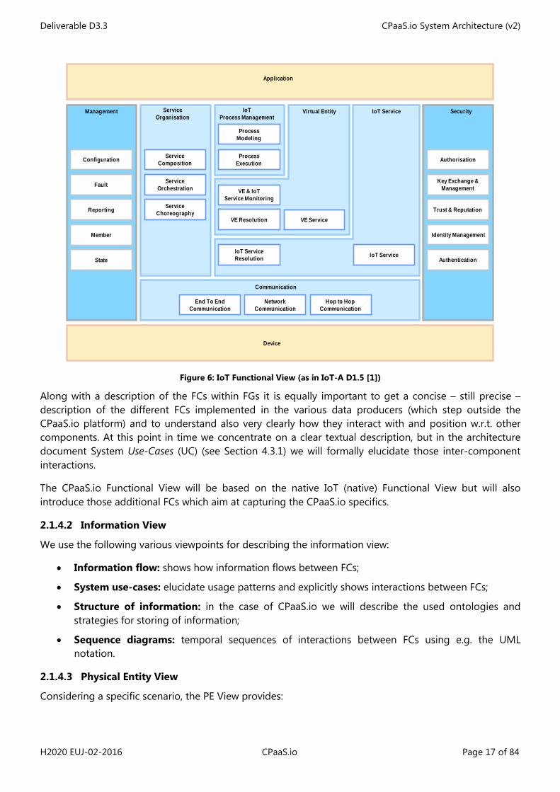
In this section we provide a reminder (see Figure 6 below) of the “native” IoT-A Functional View as it shows an illustrative example of functional decomposition resulting from a thoroughly conducted requirement analysis (in that particular case it was the analysis of the IoT-A requirements coming from the different stakeholders resulting into the final list of UNIs [23]). We recommend referring to the IoT ARM final architecture deliverable D1.5 [1] in order to get more detail about the purpose of each of the Functional Components shown in that Functional View.
Man
agem
ent
Secu
rity
Application
IoT Process
Management
VirtualEntity
IoTService
Communication
Device
Service Organisation
Deliverable D3.3 CPaaS.io System Architecture (v2)
H2020 EUJ-02-2016 CPaaS.io Page 17 of 84
Figure 6: IoT Functional View (as in IoT-A D1.5 [1])
Along with a description of the FCs within FGs it is equally important to get a concise – still precise – description of the different FCs implemented in the various data producers (which step outside the CPaaS.io platform) and to understand also very clearly how they interact with and position w.r.t. other components. At this point in time we concentrate on a clear textual description, but in the architecture document System Use-Cases (UC) (see Section 4.3.1) we will formally elucidate those inter-component interactions.
The CPaaS.io Functional View will be based on the native IoT (native) Functional View but will also introduce those additional FCs which aim at capturing the CPaaS.io specifics.
2.1.4.2 Information View
We use the following various viewpoints for describing the information view:
• Information flow: shows how information flows between FCs;
• System use-cases: elucidate usage patterns and explicitly shows interactions between FCs;
• Structure of information: in the case of CPaaS.io we will describe the used ontologies and strategies for storing of information;
• Sequence diagrams: temporal sequences of interactions between FCs using e.g. the UML notation.
2.1.4.3 Physical Entity View
Considering a specific scenario, the PE View provides:
VE Service
VE & IoTService Monitoring
VE Resolution
IoT ServiceIoT ServiceResolution
ServiceOrchestration
ServiceComposition
NetworkCommunication
End To EndCommunication
Hop to HopCommunication
Management Security
Application
Virtual Entity IoT Service
Communication
Configuration
Fault
Authorisation
Key Exchange &Management
Trust & Reputation
Identity Management
Authentication
Device
Reporting
Member
State
IoT Process Management
ProcessModeling
ProcessExecution
ServiceChoreography
ServiceOrganisation
Deliverable D3.3 CPaaS.io System Architecture (v2)
H2020 EUJ-02-2016 CPaaS.io Page 18 of 84
• The description of the Objects (hence so-called Physical Entities), their physical properties of interest and how those objects are virtualized into the cyber-spaces, explaining how the PEs are “translated” into VEs and how their physical properties can be modelled through VE properties;
• The physical association between objects and hardware devices, e.g. if a sensor is attached (touching, fixed) to the physical object or if the physical object is in the scope of a detached sensor (e.g. a camera);
• A clear description of the information captured by devices, including meta-data.
There is no CPaaS.io Context View described in this document. Such views will be provided in deliverables relating to the scenario implementation.
2.1.4.4 Context View
According to the IoT ARM [1] and Rozanki & Woods [20] the Context View describes “the relationships, dependencies and interactions between the system and its environment (the people, systems, external entities, with which it interacts)” either using plain text or UML-like notations.
The concerns addressed by the Context View cover the following aspects:
• System scope and responsibilities; • Identity of external entities and services and data used; • Nature and characteristics of external entities; • Nature and characteristics of external interfaces; • Other external dependencies; • Impact of the system upon its environment.
In the context of CPaaS.io, a dedicated Context View will be associated with each Scenario implementation and therefore will be documented within deliverables relating to scenario implementation (like for PE Views).
2.1.4.5 Deployment & Operation View
The Deployment & Operation View (or Deployment View) main purpose is to describe how the different FCs and hardware (including gateways, sensors, actuators etc.) are deployed in the “real life” according to specific scenarios. The Deployment View considers concrete FCs and individual scenarios and provides the description of the concrete platform deployments (u2- and FIWARE- based) following:
1. The respective u2-based and FIWARE-based Instantiation Views (see Sections 6.1 and 0); 2. any additional deployment of components needed for implementing the scenarios (see the cases
relating to Class-I to Class-VI data providers, where some existing infrastructure do exists outside the CPaaS.io platform).
Like for The PE and Context Views, the Deployment View is scenario specific. Each CPaaS.io scenario shall describe, using a Deployment View, how it is physically deployed in the field (with information about infrastructure at the RDP side, network, storage and computing resources, including FCs that are part of that Scenario-specific infrastructure (e.g. Semantic Annotator, Resource Manager, Data and Service endpoints…)).
2.1.5 IoT ARM Perspectives
According to Rozanski & Woods [20] an architectural Perspective “is a collection of activities, tactics and guidelines that are used to ensure that a system exhibits a particular set of related quality properties that require consideration across a number of the system’s architectural views”.
Deliverable D3.3 CPaaS.io System Architecture (v2)
H2020 EUJ-02-2016 CPaaS.io Page 19 of 84
In this definition, a quality property is meant to be “an externally visible, non-functional property of a system such as performance, security or scalability” [20].
As we can see architectural Perspectives are orthogonal to architectural Views; therefore any architecture or design decision pertaining to non-functional or quality requirements often spans more than one architectural View, if not all. Following the methodology from Rozanski & Woods [20], the IoT ARM leverages this methodology and proposes to approach and structure those transversal aspects of architecture using a comprehensive list of perspectives that focus on specific non-functional requirements or desired quality properties of the architecture, with special focus on the IoT domain. The IoT ARM proposes the following structure as far as “aspects” of an architecture are concerned:
• Evolution (or Evolvability): is a quality of a system that has been designed in such a way it can easily be adapted to new technologies;
• Interoperability: ability of a system to easily interoperate with other systems at various levels like technical, syntactical, semantic and organisational [12]
• Availability: ability of a system to be fully (or partly) available when required2 • Resilience: ability of a system to effectively handle failure or attacks that could affect the system
availability2 • Trust, Security and Privacy:
o Security: ability of the system to reliably control, monitor and audit who can perform what actions on what resources, to detect and recover from failures insecurity mechanisms and to resist to cyber attacks2
o Trust: ability of a system to establish and enforce trusted relation between the different parties involved in a system (end-users, component, data) in such a way system operation and behaviours comply to expected ones
o Privacy: ability of a system to deal with all kind of personal data and in particular to implement reliably privacy policies about accessing, sharing that data or hiding people’s identity
• Performance: ability of a system to predictably perform its operations within its mandated performance requirements and profile2
• Scalability: ability of the system to cope with increasing demand in computing, networking, storage resulting from increasing volume of system usage2
• Usability: quality that illustrate how easy a system can be used, how easy data can be apprehended by the end users, how easy the GUI is understandable and ergonomic while maintaining efficient work
Of course the list of qualities can be updated or adapted according to architects’ needs.
Each desired quality will be then associated with a set of activities (for instance activities associated with Trust, Security and Privacy are the collection of trust requirements, the conduction of risk and threat analysis, the definition of a trust model, etc.
Then defining a certain number of tactics allows showing how the desired system quality can be eventually reached. Because a tactic can span more than one view, the implementation of a tactic through Design Choices (DC) can lead to more than one of those DCs (e.g. a tactic for realizing semantic interoperability can lead to a collection of DCs relating to Data Structure for the Information View and DCs relating to interfaces, storage and protocols for the Functional View).
2 adapted from [30]
Deliverable D3.3 CPaaS.io System Architecture (v2)
H2020 EUJ-02-2016 CPaaS.io Page 20 of 84
2.2 Using the IoT ARM in the context of CPaaS.io
In CPaaS.io we are using the IoT ARM in order to agree, between EU and Japanese colleagues, on the one hand about the logical functionalities (i.e. FCs) that a CPaaS.io concrete platform must provide, and on the other hand about the nature and sequences of interactions that must take place between those logical functional components in order to accomplish typical actions like producing data, consuming data etc. (i.e. system UCs).
The following Section 4 is therefore about identifying and defining all needed FCs, based partly on functional requirements (see Section 4.2), taking as a starting point the functional decomposition provided by IoT-A [1] and describing such sequence of interactions (see Information View/system UCs in Section 4.3.1).
2.2.1 Views
Since Japanese and European consortia are taking different technical approaches when it comes to implementing a concrete platform (respectively u2- and FIWARE- based), we need to provide two additional architectural views (called Instantiation Views), the role of which is:
1. to identify available and still-to-be-implemented u2-based (resp. FIWARE-based) concrete components;
2. to show how that list of concrete components map to the list of logical FCs (so that we can identifying coverage and gaps);
3. to provide an architectural view of the whole u2-based (resp. FIWARE-based) concrete architecture, i.e. instantiation of the common ARM-driven logical system architecture;
4. to show concrete instantiations of the system UCs featured in Section 4.3.1, using the u2-based (resp. FIWARE-based) concrete components.
2.2.2 Perspectives
As far as CPaaS.io is concerned, we will need to synchronise and align, between Japanese and EU partners, about 1/ the desired system properties or qualities and 2/ tactics to be followed, taking also into account that two platforms based upon two different technologies (u2 and FIWARE), need to offer the highest possible level of interoperability (interoperability being itself a perspective). The Volere template shows an initial mapping of the non-functional requirements to the list of Perspectives listed in Section 2.1.5.
3 CPaaS.io Requirements Analysis and Mapping
3.1 Summary of requirement collection phase
In the three following sub-sections we come back on the results of the two previous WP2 and WP3 phases (achieved between M1 and M3 and concluded with respectively D2.1 and D3.1) and provide three lists of requirements:
1. Scenario requirements: requirements from the CPaaS.io scenario point of view (Section 3.1.1) as introduced in D2.1
2. Platform requirements: functional requirements (Section 3.1.3) and non-functional requirements (Section 3.1.2) as introduced in D3.1
Deliverable D3.3 CPaaS.io System Architecture (v2)
H2020 EUJ-02-2016 CPaaS.io Page 21 of 84
The purpose of this section is then the analysis and unification of those requirements into a single list of unified requirements (called UNIs in the IoT-A terminology). The following step will be the mapping to views and perspectives, as explained in the previous introductory sections.
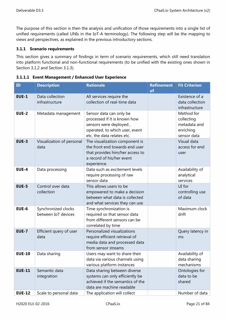
3.1.1 Scenario requirements
This section gives a summary of findings in term of scenario requirements, which still need translation into platform functional and non-functional requirements (to be unified with the existing ones shown in Section 3.1.2 and Section 3.1.3).
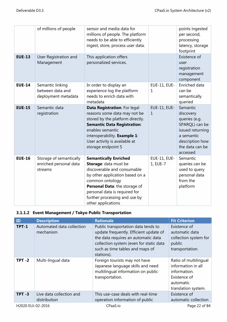
3.1.1.1 Event Management / Enhanced User Experience
ID Description Rationale Refinement of
Fit Criterion
EUE-1 Data collection infrastructure
All services require the collection of real-time data
Existence of a data collection infrastructure
EUE-2 Metadata management Sensor data can only be processed if it is known how sensors were deployed , operated, to which user, event etc. the data relates etc.
Method for collecting metadata and enriching sensor data
EUE-3 Visualization of personal data
The visualization component is the front end towards end user that provides him/her access to a record of his/her event experience.
Visual data access for end user
EUE-4 Data processing Data such as excitement levels require processing of raw sensor data
Availability of analytical services
EUE-5 Control over data collection
This allows users to be empowered to make a decision between what data is collected and what services they can use
UI for controlling use of data
EUE-6 Synchronized clocks between IoT devices
Time synchronization is required so that sensor data from different sensors can be correlated by time
Maximum clock drift
EUE-7 Efficient query of user data
Personalized visualizations require efficient retrieval of media data and processed data from sensor streams
Query latency in ms
EUE-10 Data sharing Users may want to share their data via various channels using various platform instances
Availability of data sharing mechanisms
EUE-11 Semantic data integration
Data sharing between diverse systems can only efficiently be achieved if the semantics of the data are machine readable
Ontologies for data to be shared
EUE-12 Scale to personal data The application will collect Number of data
Deliverable D3.3 CPaaS.io System Architecture (v2)
H2020 EUJ-02-2016 CPaaS.io Page 22 of 84
of millions of people sensor and media data for millions of people. The platform needs to be able to efficiently ingest, store, process user data.
points ingested per second, processing latency, storage footprint
EUE-13 User Registration and Management
This application offers personalized services.
Existence of user registration management component
EUE-14 Semantic linking between data and deployment metadata
In order to display an experience log the platform needs to enrich data with metadata
EUE-11, EUE-1
Enriched data can be semantically queried
EUE-15 Semantic data registration
Data Registration: For legal reasons some data may not be stored by the platform directly. Semantic Data Registration: enables semantic interoperability. Example 1: User activity is available at storage endpoint S
EUE-11, EUE-1
Semantic discovery queries (e.g. SPARQL) can be issued returning a semantic description how the data can be accessed
EUE-16 Storage of semantically enriched personal data streams
Semantically Enriched Storage: data must be discoverable and consumable by other application based on a common ontology Personal Data: the storage of personal data is required for further processing and use by other applications
EUE-11, EUE-1, EUE-7
Semantic queries can be used to query personal data from the platform
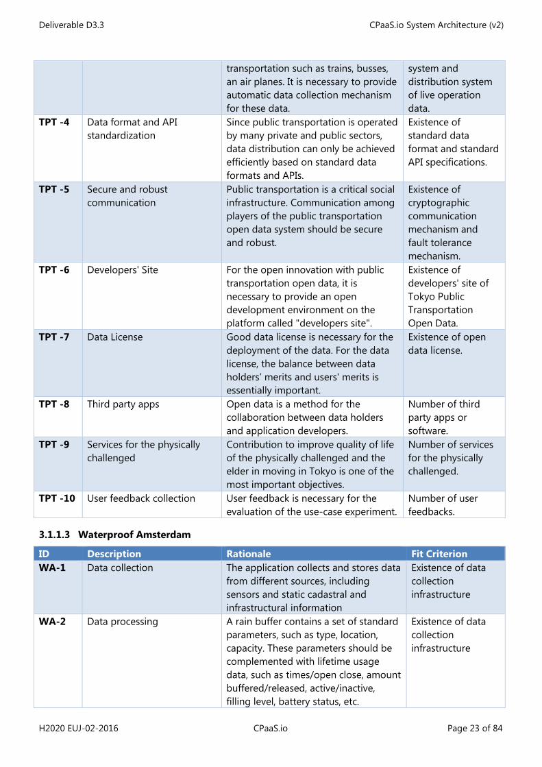
3.1.1.2 Event Management / Tokyo Public Transportation
ID Description Rationale Fit Criterion TPT-1 Automated data collection
mechanism Public transportation data tends to update frequently. Efficient update of the data requires an automatic data collection system (even for static data such as time tables and maps of stations).
Existence of automatic data collection system for public transportation.
TPT -2 Multi-lingual data Foreign tourists may not have Japanese language skills and need multilingual information on public transportation.
Ratio of multilingual information in all information. Existence of automatic translation system.
TPT -3 Live data collection and distribution
This use-case deals with real-time operation information of public
Existence of automatic collection
Deliverable D3.3 CPaaS.io System Architecture (v2)
H2020 EUJ-02-2016 CPaaS.io Page 23 of 84
transportation such as trains, busses, an air planes. It is necessary to provide automatic data collection mechanism for these data.
system and distribution system of live operation data.
TPT -4 Data format and API standardization
Since public transportation is operated by many private and public sectors, data distribution can only be achieved efficiently based on standard data formats and APIs.
Existence of standard data format and standard API specifications.
TPT -5 Secure and robust communication
Public transportation is a critical social infrastructure. Communication among players of the public transportation open data system should be secure and robust.
Existence of cryptographic communication mechanism and fault tolerance mechanism.
TPT -6 Developers' Site For the open innovation with public transportation open data, it is necessary to provide an open development environment on the platform called "developers site".
Existence of developers' site of Tokyo Public Transportation Open Data.
TPT -7 Data License Good data license is necessary for the deployment of the data. For the data license, the balance between data holders’ merits and users' merits is essentially important.
Existence of open data license.
TPT -8 Third party apps Open data is a method for the collaboration between data holders and application developers.
Number of third party apps or software.
TPT -9 Services for the physically challenged
Contribution to improve quality of life of the physically challenged and the elder in moving in Tokyo is one of the most important objectives.
Number of services for the physically challenged.
TPT -10 User feedback collection User feedback is necessary for the evaluation of the use-case experiment.
Number of user feedbacks.
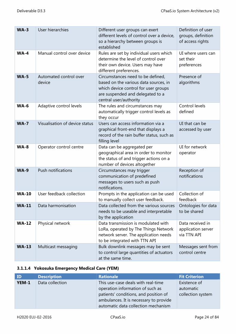
3.1.1.3 Waterproof Amsterdam
ID Description Rationale Fit Criterion WA-1 Data collection The application collects and stores data
from different sources, including sensors and static cadastral and infrastructural information
Existence of data collection infrastructure
WA-2 Data processing A rain buffer contains a set of standard parameters, such as type, location, capacity. These parameters should be complemented with lifetime usage data, such as times/open close, amount buffered/released, active/inactive, filling level, battery status, etc.
Existence of data collection infrastructure
Deliverable D3.3 CPaaS.io System Architecture (v2)
H2020 EUJ-02-2016 CPaaS.io Page 24 of 84
WA-3 User hierarchies Different user groups can exert different levels of control over a device, so a hierarchy between groups is established
Definition of user groups, definition of access rights
WA-4 Manual control over device Rules are set by individual users which determine the level of control over their own device. Users may have different preferences.
UI where users can set their preferences
WA-5 Automated control over device
Circumstances need to be defined, based on the various data sources, in which device control for user groups are suspended and delegated to a central user/authority
Presence of algorithms
WA-6 Adaptive control levels The rules and circumstances may automatically trigger control levels as they occur
Control levels defined
WA-7 Visualisation of device status Users can access information via a graphical front-end that displays a record of the rain buffer status, such as filling level
UI that can be accessed by user
WA-8 Operator control centre Data can be aggregated per geographical area in order to monitor the status of and trigger actions on a number of devices altogether
UI for network operator
WA-9 Push notifications Circumstances may trigger communication of predefined messages to users such as push notifications.
Reception of notifications
WA-10 User feedback collection Prompts in the application can be used to manually collect user feedback.
Collection of feedback
WA-11 Data harmonisation Data collected from the various sources needs to be useable and interpretable by the application
Ontologies for data to be shared
WA-12 Physical network Data transmission is modulated with LoRa, operated by The Things Network network server. The application needs to be integrated with TTN API
Data received in application server via TTN API
WA-13 Multicast messaging Bulk downlink messages may be sent to control large quantities of actuators at the same time.
Messages sent from control centre
3.1.1.4 Yokosuka Emergency Medical Care (YEM)
ID Description Rationale Fit Criterion YEM-1 Data collection This use-case deals with real-time
operation information of such as patients' conditions, and position of ambulances. It is necessary to provide automatic data collection mechanism
Existence of automatic collection system
Deliverable D3.3 CPaaS.io System Architecture (v2)
H2020 EUJ-02-2016 CPaaS.io Page 25 of 84
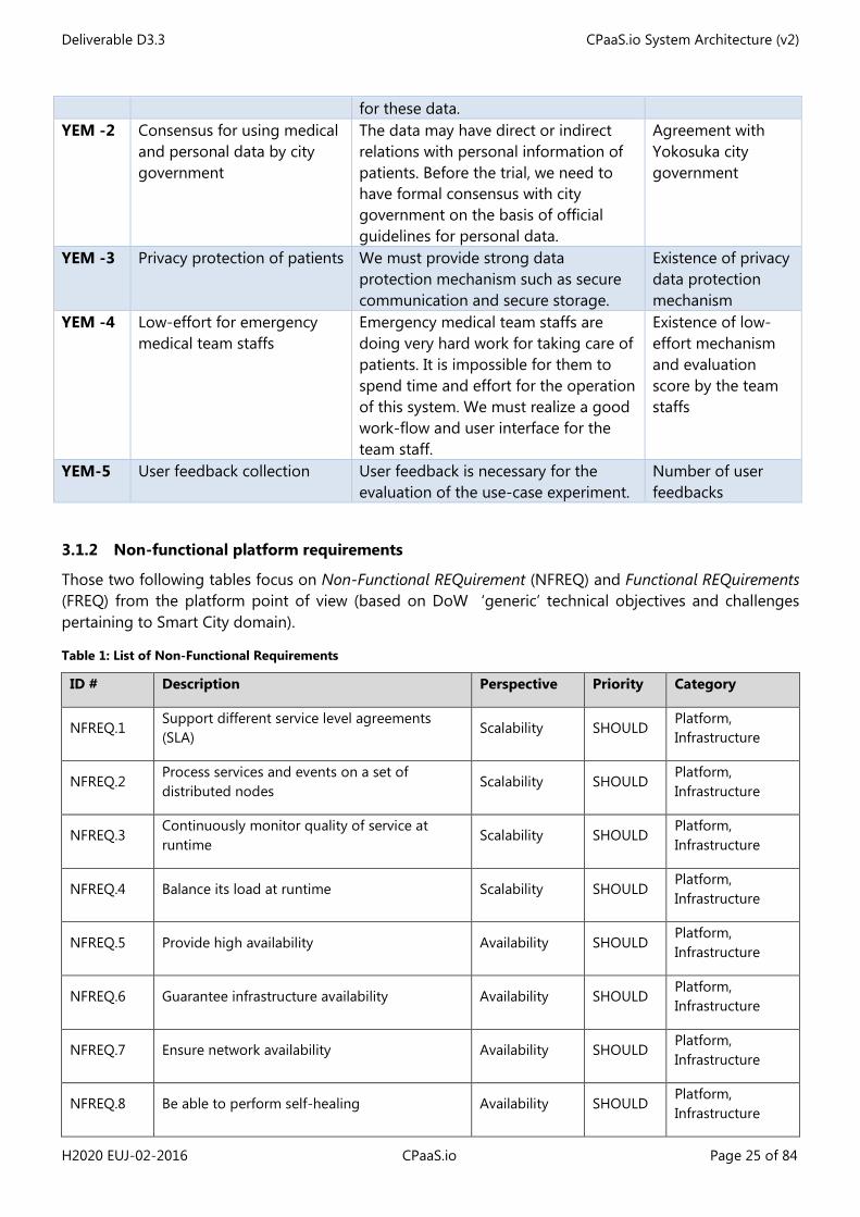
for these data. YEM -2 Consensus for using medical
and personal data by city government
The data may have direct or indirect relations with personal information of patients. Before the trial, we need to have formal consensus with city government on the basis of official guidelines for personal data.
Agreement with Yokosuka city government
YEM -3 Privacy protection of patients We must provide strong data protection mechanism such as secure communication and secure storage.
Existence of privacy data protection mechanism
YEM -4 Low-effort for emergency medical team staffs
Emergency medical team staffs are doing very hard work for taking care of patients. It is impossible for them to spend time and effort for the operation of this system. We must realize a good work-flow and user interface for the team staff.
Existence of low-effort mechanism and evaluation score by the team staffs
YEM-5 User feedback collection User feedback is necessary for the evaluation of the use-case experiment.
Number of user feedbacks
3.1.2 Non-functional platform requirements
Those two following tables focus on Non-Functional REQuirement (NFREQ) and Functional REQuirements (FREQ) from the platform point of view (based on DoW ‘generic’ technical objectives and challenges pertaining to Smart City domain).
Table 1: List of Non-Functional Requirements
ID # Description Perspective Priority Category
NFREQ.1 Support different service level agreements (SLA)
Scalability SHOULD Platform, Infrastructure
NFREQ.2 Process services and events on a set of distributed nodes
Scalability SHOULD Platform, Infrastructure
NFREQ.3 Continuously monitor quality of service at runtime
Scalability SHOULD Platform, Infrastructure
NFREQ.4 Balance its load at runtime Scalability SHOULD Platform, Infrastructure
NFREQ.5 Provide high availability Availability SHOULD Platform, Infrastructure
NFREQ.6 Guarantee infrastructure availability Availability SHOULD Platform, Infrastructure
NFREQ.7 Ensure network availability Availability SHOULD Platform, Infrastructure
NFREQ.8 Be able to perform self-healing Availability SHOULD Platform, Infrastructure
Deliverable D3.3 CPaaS.io System Architecture (v2)
H2020 EUJ-02-2016 CPaaS.io Page 26 of 84
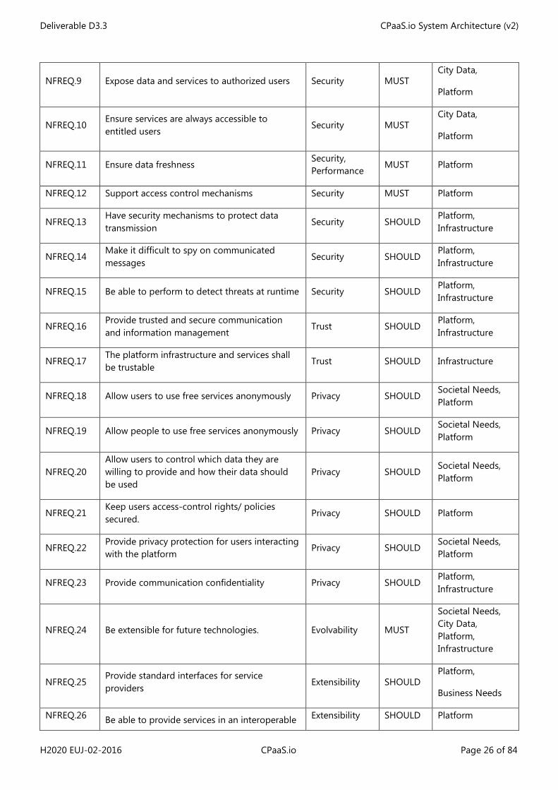
NFREQ.9 Expose data and services to authorized users Security MUST City Data,
Platform
NFREQ.10 Ensure services are always accessible to entitled users
Security MUST City Data,
Platform
NFREQ.11 Ensure data freshness Security, Performance
MUST Platform
NFREQ.12 Support access control mechanisms Security MUST Platform
NFREQ.13 Have security mechanisms to protect data transmission
Security SHOULD Platform, Infrastructure
NFREQ.14 Make it difficult to spy on communicated messages
Security SHOULD Platform, Infrastructure
NFREQ.15 Be able to perform to detect threats at runtime Security SHOULD Platform, Infrastructure
NFREQ.16 Provide trusted and secure communication and information management
Trust SHOULD Platform, Infrastructure
NFREQ.17 The platform infrastructure and services shall be trustable
Trust SHOULD Infrastructure
NFREQ.18 Allow users to use free services anonymously Privacy SHOULD Societal Needs, Platform
NFREQ.19 Allow people to use free services anonymously Privacy SHOULD Societal Needs, Platform
NFREQ.20 Allow users to control which data they are willing to provide and how their data should be used
Privacy SHOULD Societal Needs, Platform
NFREQ.21 Keep users access-control rights/ policies secured.
Privacy SHOULD Platform
NFREQ.22 Provide privacy protection for users interacting with the platform
Privacy SHOULD Societal Needs, Platform
NFREQ.23 Provide communication confidentiality Privacy SHOULD Platform, Infrastructure
NFREQ.24 Be extensible for future technologies. Evolvability MUST
Societal Needs, City Data, Platform, Infrastructure
NFREQ.25 Provide standard interfaces for service providers
Extensibility SHOULD Platform,
Business Needs
NFREQ.26 Be able to provide services in an interoperable Extensibility SHOULD Platform
Deliverable D3.3 CPaaS.io System Architecture (v2)
H2020 EUJ-02-2016 CPaaS.io Page 27 of 84
manner
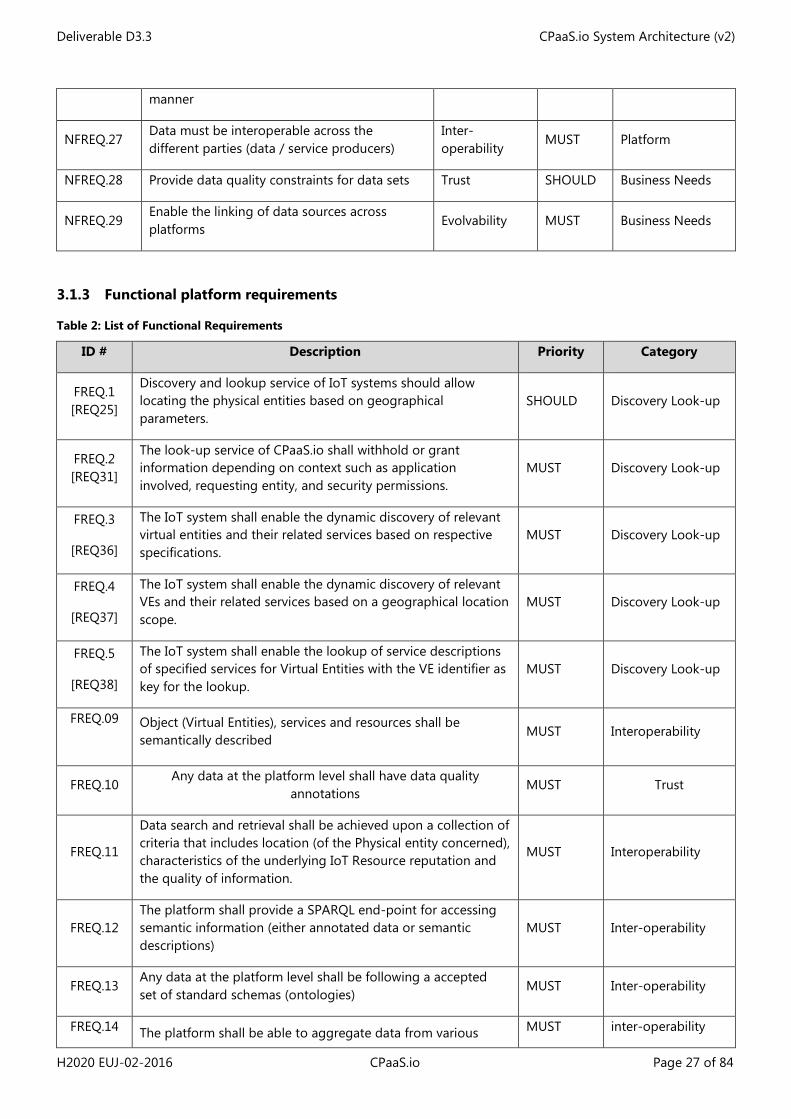
NFREQ.27 Data must be interoperable across the different parties (data / service producers)
Inter-operability
MUST Platform
NFREQ.28 Provide data quality constraints for data sets Trust SHOULD Business Needs
NFREQ.29 Enable the linking of data sources across platforms
Evolvability MUST Business Needs
3.1.3 Functional platform requirements
Table 2: List of Functional Requirements
ID # Description Priority Category
FREQ.1 [REQ25]
Discovery and lookup service of IoT systems should allow locating the physical entities based on geographical parameters.
SHOULD Discovery Look-up
FREQ.2 [REQ31]
The look-up service of CPaaS.io shall withhold or grant information depending on context such as application involved, requesting entity, and security permissions.
MUST Discovery Look-up
FREQ.3
[REQ36]
The IoT system shall enable the dynamic discovery of relevant virtual entities and their related services based on respective specifications.
MUST Discovery Look-up
FREQ.4
[REQ37]
The IoT system shall enable the dynamic discovery of relevant VEs and their related services based on a geographical location scope.
MUST Discovery Look-up
FREQ.5
[REQ38]
The IoT system shall enable the lookup of service descriptions of specified services for Virtual Entities with the VE identifier as key for the lookup.
MUST Discovery Look-up
FREQ.09
Object (Virtual Entities), services and resources shall be semantically described
MUST Interoperability
FREQ.10 Any data at the platform level shall have data quality
annotations MUST Trust
FREQ.11
Data search and retrieval shall be achieved upon a collection of criteria that includes location (of the Physical entity concerned), characteristics of the underlying IoT Resource reputation and the quality of information.
MUST Interoperability
FREQ.12 The platform shall provide a SPARQL end-point for accessing semantic information (either annotated data or semantic descriptions)
MUST Inter-operability
FREQ.13 Any data at the platform level shall be following a accepted set of standard schemas (ontologies)
MUST Inter-operability
FREQ.14 The platform shall be able to aggregate data from various MUST inter-operability
Deliverable D3.3 CPaaS.io System Architecture (v2)
H2020 EUJ-02-2016 CPaaS.io Page 28 of 84
sources using LOD principles
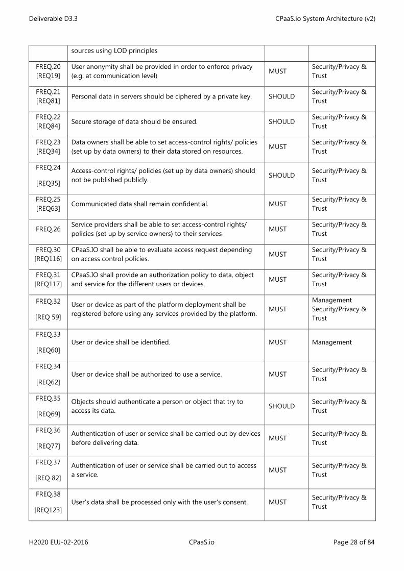
FREQ.20 [REQ19]
User anonymity shall be provided in order to enforce privacy (e.g. at communication level)
MUST Security/Privacy & Trust
FREQ.21 [REQ81]
Personal data in servers should be ciphered by a private key. SHOULD Security/Privacy & Trust
FREQ.22 [REQ84]
Secure storage of data should be ensured. SHOULD Security/Privacy & Trust
FREQ.23 [REQ34]
Data owners shall be able to set access-control rights/ policies (set up by data owners) to their data stored on resources.
MUST Security/Privacy & Trust
FREQ.24
[REQ35]
Access-control rights/ policies (set up by data owners) should not be published publicly.
SHOULD Security/Privacy & Trust
FREQ.25 [REQ63]
Communicated data shall remain confidential. MUST Security/Privacy & Trust
FREQ.26 Service providers shall be able to set access-control rights/ policies (set up by service owners) to their services
MUST Security/Privacy & Trust
FREQ.30 [REQ116]
CPaaS.IO shall be able to evaluate access request depending on access control policies.
MUST Security/Privacy & Trust
FREQ.31 [REQ117]
CPaaS.IO shall provide an authorization policy to data, object and service for the different users or devices.
MUST Security/Privacy & Trust
FREQ.32
[REQ 59]
User or device as part of the platform deployment shall be registered before using any services provided by the platform.
MUST Management Security/Privacy & Trust
FREQ.33
[REQ60] User or device shall be identified. MUST Management
FREQ.34
[REQ62] User or device shall be authorized to use a service. MUST
Security/Privacy & Trust
FREQ.35
[REQ69]
Objects should authenticate a person or object that try to access its data.
SHOULD Security/Privacy & Trust
FREQ.36
[REQ77]
Authentication of user or service shall be carried out by devices before delivering data.
MUST Security/Privacy & Trust
FREQ.37
[REQ 82]
Authentication of user or service shall be carried out to access a service.
MUST Security/Privacy & Trust
FREQ.38
[REQ123] User's data shall be processed only with the user's consent. MUST
Security/Privacy & Trust
Deliverable D3.3 CPaaS.io System Architecture (v2)
H2020 EUJ-02-2016 CPaaS.io Page 29 of 84
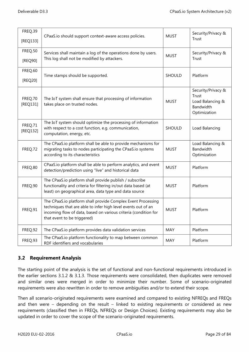
FREQ.39
[REQ133] CPaaS.io should support context-aware access policies. MUST
Security/Privacy & Trust
FREQ.50
[REQ90]
Services shall maintain a log of the operations done by users. This log shall not be modified by attackers.
MUST Security/Privacy & Trust
FREQ.60
[REQ20] Time stamps should be supported. SHOULD Platform
FREQ.70 [REQ131]
The IoT system shall ensure that processing of information takes place on trusted nodes.
MUST
Security/Privacy & Trust Load Balancing & Bandwidth Optimization
FREQ.71 [REQ132]
The IoT system should optimize the processing of information with respect to a cost function, e.g. communication, computation, energy, etc.
SHOULD Load Balancing
FREQ.72 The CPaaS.io platform shall be able to provide mechanisms for migrating tasks to nodes participating the CPaaS.io systems according to its characteristics
MUST Load Balancing & Bandwidth Optimization
FREQ.80 CPaaS.io platform shall be able to perform analytics, and event detection/prediction using “live” and historical data
MUST Platform
FREQ.90 The CPaaS.io platform shall provide publish / subscribe functionality and criteria for filtering in/out data based (at least) on geographical area, data type and data source
MUST Platform
FREQ.91
The CPaaS.io platform shall provide Complex Event Processing techniques that are able to infer high level events out of an incoming flow of data, based on various criteria (condition for that event to be triggered)
MUST Platform
FREQ.92 The CPaaS.io platform provides data validation services MAY Platform
FREQ.93 The CPaaS.io platform functionality to map between common RDF identifiers and vocabularies
MAY Platform
3.2 Requirement Analysis
The starting point of the analysis is the set of functional and non-functional requirements introduced in the earlier sections 3.1.2 & 3.1.3. Those requirements were consolidated, then duplicates were removed and similar ones were merged in order to minimize their number. Some of scenario-originated requirements were also rewritten in order to remove ambiguities and/or to extend their scope.
Then all scenario-originated requirements were examined and compared to existing NFREQs and FREQs and then were – depending on the result – linked to existing requirements or considered as new requirements (classified then in FREQs, NFREQs or Design Choices). Existing requirements may also be updated in order to cover the scope of the scenario-originated requirements.
Deliverable D3.3 CPaaS.io System Architecture (v2)
H2020 EUJ-02-2016 CPaaS.io Page 30 of 84
The result of this analysis consists therefore of a list of UNIs which are fully captured in the Volere template (technical Annex to this document).
An initial requirement mapping as been also achieved, with mapping to Views, Perspectives, Functional Groups and Functional Components.
Many comments are also associated to those requirements and will be used to feed forthcoming technical discussions (towards the next architecture release e.g.).
4 CPaaS.io Views
4.1 Actors involved in data production
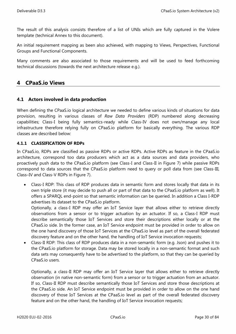
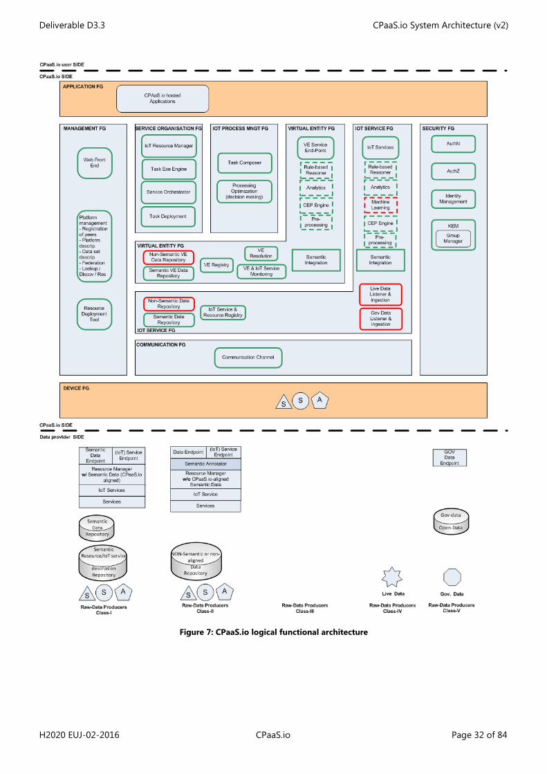
When defining the CPaaS.io logical architecture we needed to define various kinds of situations for data provision, resulting in various classes of Raw Data Providers (RDP) numbered along decreasing capabilities; Class-I being fully semantics-ready while Class-IV does not own/manage any local infrastructure therefore relying fully on CPaaS.io platform for basically everything. The various RDP classes are described below:
4.1.1 CLASSIFICATION OF RDPs
In CPaaS.io, RDPs are classified as passive RDPs or active RDPs. Active RDPs as feature in the CPaaS.io architecture, correspond too data producers which act as a data sources and data providers, who proactively push data to the CPaaS.io platform (see Class-I and Class-II in Figure 7) while passive RDPs correspond to data sources that the CPaaS.io platform need to query or poll data from (see Class-III, Class–IV and Class-V RDPs in Figure 7).
• Class-I RDP: This class of RDP produces data in semantic form and stores locally that data in its own triple store (it may decide to push all or part of that data to the CPaaS.io platform as well). It offers a SPARQL end-point so that semantic information can be queried. In addition a Class I-RDP advertises its dataset to the CPaaS.io platform. Optionally, a class-I RDP may offer an IoT Service layer that allows either to retrieve directly observations from a sensor or to trigger actuation by an actuator. If so, a Class-I RDP must describe semantically those IoT Services and store their descriptions either locally or at the CPaaS.io side. In the former case, an IoT Service endpoint must be provided in order to allow on the one hand discovery of those IoT Services at the CPaaS.io level as part of the overall federated discovery feature and on the other hand, the handling of IoT Service invocation requests;
• Class-II RDP: This class of RDP produces data in a non-semantic form (e.g. Json) and pushes it to the CPaaS.io platform for storage. Data may be stored locally in a non-semantic format and such data sets may consequently have to be advertised to the platform, so that they can be queried by CPaaS.io users. Optionally, a class-II RDP may offer an IoT Service layer that allows either to retrieve directly observation (in native non-semantic form) from a sensor or to trigger actuation from an actuator. If so, Class-II RDP must describe semantically those IoT Services and store those descriptions at the CPaaS.io side. An IoT Service endpoint must be provided in order to allow on the one hand discovery of those IoT Services at the CPaaS.io level as part of the overall federated discovery feature and on the other hand, the handling of IoT Service invocation requests;
Deliverable D3.3 CPaaS.io System Architecture (v2)
H2020 EUJ-02-2016 CPaaS.io Page 31 of 84
• Class-III RDP: In the fourth case, the RDP only manages its IoT Resources locally and relies on CPaaS.io for everything else. In an initial pre-configuration phase it needs to upload its production policy as well as the IoT Services exposing its IoT Resources to the CPaaS.io platform (resp. to the Resource Manager FC and IoT Service FC). It does not provide locally any direct data endpoint, however IoT Services can be of course invoked at the platform level;
• Class-IV RDP: they refer in the CPaaS.io architecture to Web third parties, like social media platforms producing live data e.g. twitter, news feeds, RSS …;
• Class-V RDP: they refer to open Government data, e.g., data stored in CKAN repositories.
NOTE: The various use-cases relating to Class-IV and –V will be dealt with in the third release of the CPaaS.io architecture.
4.2 CPaaS.io Functional View
Each sub-section below provides a textual description for each FC and a list of functionalities provided by the FC.
Below is a second version of the logical functional decomposition featuring the current list of FCs which will be confirmed, updated and extended during the forthcoming architecture iterations. The legend is as follows:
• In Green: FCs which were already identified in D3.2. • In Red: the new FCS introduced in this iteration. • In Dashed lines: FCs which could be deployed at the edge, closer to the data.
Deliverable D3.3 CPaaS.io System Architecture (v2)
H2020 EUJ-02-2016 CPaaS.io Page 32 of 84
Figure 7: CPaaS.io logical functional architecture
Deliverable D3.3 CPaaS.io System Architecture (v2)
H2020 EUJ-02-2016 CPaaS.io Page 33 of 84
4.2.1 MANAGEMENT FG
The management FG groups a set of FCs offering management functionalities in order to manage platforms and platform federation.
4.2.1.1 Web Front-End FC
The Web Front-End FC is a component that offers a web interface to many of the FCs implemented across the various FGs. Those components include, but are not limited to:
• All management functionalities; • Discovery and browsing of VE, VE properties, IoT service, IoT Resources, data sets etc.; • Look-up and resolution; • Definition of access and privacy policies; • Management of credentials.
4.2.1.2 Platform Management FC
Platform Management FC is responsible for managing configurations and platform-related aspects of CPaaS.io IoT architecture.
This component deals with both intra- and inter- platform management. Different aspects are covered like:
• Platform federation: Registration of peers and inter-peer links, definition of nature of links between the different platform instances and the functionalities they are supporting: federated data query, discovery, task composing spanning multiple instances, etc.;
• Task deployment: in order to enable smart and flexible deployment of tasks within the platform (see the Task Deployment FC) and in particular towards the platform edge, information about the platform components like network capacity, CPU and memory capacities need to be known at the platform level;
• Management of security across the various platform instances and domains; • Publishing of new data/knowledge or replication of data from one platform instance to another
(e.g. considering a hierarchical model from leaves towards the root) in order to allow multiple input CEP or data processing.
Platform management is an essential requirement for realization of the CPaaS.io platform due to the distributed nature of IoT. In the CPaaS.io platform, there will be vast number of IoT Devices (e.g. sensor nodes) and various hardware and software components. Moreover, different deployments from Japan and Europe may be connected to each other and exchange information based on the federation concept.
4.2.1.3 Resource Deployment Tool FC
The Resource Deployment component is a web-based front end for managing the deployment of IoT Devices. It covers an inventory for managing IoT Devices and sensors and allows IoT deployment managers to plan a deployment of physical devices including a description (location, time, floor plan) of deployments. The tool supports both the deployment of static and mobile devices. The management of mobile devices is realized by associations with mobile entities such as people. The data generated by this tool is used for metadata enrichment of raw data and analytic results as described in deliverable D2.2 [3]".
Deployment metadata created by the tool instantiates a deployment ontology extending the SSN ontology (see D6.1 for further details about the ontology) and is stored as RDF triples in a triple store (deployment knowledge base) within the platform. An initial version of the deployment tool is available
Deliverable D3.3 CPaaS.io System Architecture (v2)
H2020 EUJ-02-2016 CPaaS.io Page 34 of 84
to partners in the project. The deployment knowledge base currently contains inventory and deployment metadata for the “Color Run” event.
4.2.2 IOT PROCESS MANAGEMENT FG
4.2.2.1 Task Composer FC
Task Composer FC is a component which can be configured by developers to create necessary tasks for certain services. Each task is a data processing application that takes certain NGSI entity data in, performs some internal data processing logic, and then produces some updates to existing or new entity data. A service is a flow graph, which consists of multiple linked tasks to form some high-level data processing logic. In more advanced settings, tasks can be composed automatically by the Task Composer FC itself. To execute a service, there is need for defining the set of tasks. This FC decides how many tasks necessary for the service as well as how the tasks are organized. Examples of task includes the FCs - shown as dashed rectangles in Figure 7 - that could be deployed closer to the edge for execution depending on the node capabilities. The concept of task (and related activities) will be developed further in the next iterations of the CPaaS.io architecture.
4.2.2.2 Process Optimization FC
Process Optimization FC is a component that decides on how to execute the processes that are required for providing services. This optimization includes or relies on aspects such as the order of execution of the tasks, the necessary inputs and needed configurations for optimized performance, as well as the optimization algorithms for the processes. Process Optimization FC makes decisions based on improving the performance of the processes.
4.2.3 SERVICE ORGANISATION FG
4.2.3.1 IoT Resource Manager FC
The Resource Manager FC is an agent/component which can be configured and used by infrastructure-less owners of IoT Resources (see the RDP Class-III case) in order to manage the reading of their IoT Resources and its periodicity.
This FC allows RDPs for defining publishing policies and relies on CPaaS.io-hosted IoT Services which are deployed by the RDPs Class-III and which are exposing the IoT Resources under the RDPs’ responsibility.
4.2.3.2 Service Orchestrator FC
Service orchestrator FC is the component which generates task instances and manages execution of these task instances based on the available resources. In order to perform this role, the Service Orchestrator FC must know about the availability of the resources such as the cloud or edge resources (e.g., servers). It monitors the usage of resources and the status of all running tasks on the nodes.
This FC manages all the tasks and the execution of task instances over the edge nodes or cloud nodes. Hence, the assignment of task instances to the available resources is handled by Service Orchestrator FC.
4.2.3.3 Task Deployment FC
Task Deployment FC takes the assignment from Service Orchestrator FC as an input and performs the necessary deployment of task instances. It aims to minimize the cross-edge node and cross-site network traffic while doing these deployments by generating a deployment plan and performs the task deployment on the available cloud or edge resources based on a deployment plan.
Deliverable D3.3 CPaaS.io System Architecture (v2)
H2020 EUJ-02-2016 CPaaS.io Page 35 of 84
4.2.3.4 Task Execution Engine FC
Task Execution Engine FC is the component that executes the tasks that are defined by the Task Composer FC and deployed by the Task Deployment FC based on the available resources. The instantiation of this FC is a worker that executes the necessary tasks.
4.2.4 VIRTUAL ENTITY FG
As explained earlier in Section 2.1.3.3 this FG deals with all aspects pertaining to Virtual Entities like storage of VE-related observations and VE/VE Service Descriptions, discovery, look-up and resolution of VEs and VE Services, discovery, look-up and resolution of Associations and VE Service endpoint. Functionalities shared with the IoT Service FG are handled in Section 4.2.6.
4.2.4.1 Semantic VE Data repository FC
This FC provides a database for storing VE-related data (i.e. historical data) as well as a SPARQL endpoint for accessing that VE-related data.
4.2.4.2 Non-Semantic VE Data repository FC
This FC provides a database for storing VE data in a non-semantic form. The semantic Integration layer can later on ingest it before storing it in a semantic data store. Typical example would be –for the FIWARE based instantiation of it- VE context data expressed in the FIWARE internal NGSI format.
4.2.4.3 VE Registry FC
VE Registry FC is the component that stores, queries and retrieves VE semantic descriptions. This FC could be merged with the VE Resolution FC or can be implemented by a stand-alone component that is integrated with the VE Resolution component.
4.2.4.4 VE Resolution FC
This FC is an extension of the IoT-A native component that can be used to discover and retrieve associations existing between VEs and IoT Services. Using Associations (see Figure 4) the entity managing VE Services can know about which IoT Services should be used in order to return the value of a VE Property (as associations between VEs and IoT Services are dynamic in order to deal with mobility). In addition to providing means for retrieving those associations, this component can be used to by VEs to register their availabilities. The existing VEs that are available and registered can be discovered based on fitting the searching criteria. This search can typically be done by the VE Service endpoint FC for identifying the IoT Service to be triggered for answering a READ/UPDATE request upon a specific VE property.
4.2.4.5 VE & IoT Service Monitoring FC
This component is an IoT-A native FC responsible for automatically finding new associations, which are in turn stored by the VE Resolution FC.
4.2.4.6 VE Service End-Point FC
This FC is an extension of the IoT-A native FC that provides a unique endpoint to accessing (Read/Set) Virtual Entities and their properties. This FC is responsible for:
• Maintaining and publishing a snapshot of VE state at regular interval (sampling rate to be configured) as VE observations which are therefore also stored within the Semantic VE Data Repository FC;
Deliverable D3.3 CPaaS.io System Architecture (v2)
H2020 EUJ-02-2016 CPaaS.io Page 36 of 84
• Handling and answering requests for accessing VE properties. As explained in case 2/ in Section 4.3.1.4, answering such requests requires identifying the appropriate corresponding IoT Service via existing associations between device-level and thing-level information.
4.2.5 IOT SERVICE FG
This IoT Service FG deals with all aspects pertaining to IoT data like storage of IoT Data, discovery, look-up and Resolution of IoT Services, invocation of IoT Services, storage, discovery, look-up and resolution of IoT Service descriptions and IoT Resource descriptions.
Functionalities shared with the Virtual Entity FG are handled in Section 4.2.6.
4.2.5.1 Semantic Data Repository FC
Semantic Data Repository FC is used for storing semantic data managed at CPaaS.io level. Semantic information can be annotated sensor readings (annotated raw data coming from RDP) in the form of observation or any kind of semantic data resulting from applying analytics or from processing within the Semantic Integration FC. This FC provides a SPARQL endpoint that can be used for searching and retrieving the data from the database (either it is a full-fledge triple store or relational database with SPARQL endpoint).
4.2.5.2 Non-Semantic Data Repository FC
The Non-Semantic Data Repository is used to store non-semantic data coming e.g. from Raw Data Producers. It can be then used by other components for various tasks like CEP, analytics etc… This data can also be queried by the Semantic Integration FC in order to produce and store semantically annotated data.
4.2.5.3 IoT Service & Resource Registry FC
The IoT Service/Resource Registry3 FC provides an API for registering a Resource and the associated IoT Services within a registry with associated metadata. This particular API can be used either by CPaaS.io users for registering virtual resources and associated IoT services or by RDPs which do not handle locally the definition of the IoT Services that expose their resources (see definition of Class-II and -III).
This registry allows also to look-up IoT Services exposing IoT Resources based on various criteria (metadata).
4.2.5.4 Live Data Listener & Ingestion FC
This component is responsible for pulling data from external data sources (like e.g. Twitter RSS or news feed-which correspond to RDPs Class-IV) and putting it in an appropriate form with needed meta-data before pushing it to the appropriate repository. This FC therefore may use as well the Semantic Integration FC and may publish related knowledge to the communication FG for other components/users to use. Finally this component can also push the data to the Analytics FC or/and Machine Learning FC for further analysis (e.g. classification) before 1/ some higher-level data is published or 2/ the incoming data is enriched its meta-data before being published.
4.2.5.5 Government (Gov) Data Listener & Ingestion FC
This component behaves in a similar way to the Live Data one, but applies to open-data data sources like government, institutions or NGOs for instance (RDPs Class-V). Such data is usually accessible via CKAN 3 This FC correspond to the IoT Service Resolution FC in Figure 6
Deliverable D3.3 CPaaS.io System Architecture (v2)
H2020 EUJ-02-2016 CPaaS.io Page 37 of 84
repositories. This FC will be further developed in a next iteration of the architecture in accordance with project scenario needs.
4.2.5.6 IoT Service FC
This FC provides a REST endpoint for accessing resource data (resources are exposed to CPaas.io users by IoT Services).
4.2.6 COMMON TO VE AND IOT SERVICE FGs
4.2.6.1 Semantic Integration FC
As described in D6.1, CPaaS.io is using Linked Data and RDF to facilitate integration of data from platforms like FIWARE and u2. Neither of the two base platforms is currently supporting RDF and Linked Data out of the box. To address this, CPaaS.io is providing and integrating a semantic layer that enables mapping existing data to RDF.
This semantic integration is implemented in different phases and levels. In its first form, the semantic layer is simply exposing metadata as Linked Data, using common vocabularies and best practices as described in D6.1 [7]. This enables users to query information about available data within the FIWARE and u2 platform as Linked Data. To access this metadata layer the current implementation provides a SPARQL endpoint that can be queried.
In a second step, data residing in FIWARE or u2 can be mapped to RDF. For that, one needs to extend the appropriate data model used and introduced in D6.1, Section 3.2 [7]. This is done by a semantic middleware that can be configured accordingly. By providing appropriate tools and user interfaces, FIWARE users can thus map existing data to RDF representations. The u-code data model of u2 is close to a RDF as it stores information in a triple-like data model. The semantic integration layer needs to map internal u-code IDs to publicly used and dereferencable URIs, preferably as HTTP URIs to allow Linked Data usage. In some use-cases like the Tokyo Metro real-time data system, this is already being done and can be used as an example implementation.
To be able to query this kind of data, a SPARQL endpoint will proxy requests to the platform4. Users should be able to run SPARQL queries on data residing in FIWARE or u2.
4.2.6.2 Pre-processing FC
Pre-processing groups all kinds of algorithms that could apply straight away to the raw data before it is annotated and published. More precise description about needed algorithms will be provided in the next iteration of the architecture as soon as we get more detail about the CPaaS.io scenario developments.
4.2.6.3 Analytics FC
The Analytics FC provides a large variety of algorithms that can take as input a broad range of structured data (e.g. video streaming, time series, t-uple series) in order to perform for instance statistical analysis, machine learning, prediction, anomaly/event detection before publishing their result through the communication channel. Example of analytics (input formats, algorithms, output format) can be found in the two Instantiation Views.
4 See for example R2RML implementation in Stardog: http://docs.stardog.com/#Virtual%20Graphs
Deliverable D3.3 CPaaS.io System Architecture (v2)
H2020 EUJ-02-2016 CPaaS.io Page 38 of 84
4.2.6.4 Machine Learning FC
This component is still under discussion, but it will at least provide support for supervised classification tasks, like for instance determining if social data stemming from social media platform – e.g. tweets- should be considered as Like/Don’t Like or Neutral. See Section 6.2.1 for more detailed description of its current version.
4.2.7 COMMMUNICATION FG
4.2.7.1 Communication Channel FC
The communication channel is a FC that provides a message bus with support for publish/subscribe and publishing/consuming along topics. In the architecture it is used as a way 1/ to provide subscribers with “live data” 2/ to store data using a pre-determined topic (see UCs in Section 4.3.1)
4.2.8 SECURITY FG
The Security FG follows closely the recommendation for IoT-A native FCs as shown in Figure 6. This FG is made of several components already identified in the IoT-A Native Functional View:
• AuthN: Authentication of CPaaS.io users;
• AuthZ: Access-Control policies, decision and enforcement;
• KEM: Key Exchange and management (including as well Group Management);
• Identity Management (including also The key/X509 certificate generation).
Those different FCs are described here after in more detail.
4.2.8.1 Authentication (AuthN) FC
This AuthN5 component is responsible for enforcing the authentication of registered CPaaS.io users. Based upon a user credential passed to the AuthN FC we can make an assertion about the identity of the user i.e. that they are a known CPaaS.io users.
The AuthN component interacts with the User Management FC when the user registers in order to produce the user credentials (such credentials can take multiple forms e.g. both username/password and an X509 certificate).
When access to a resource or service is requested by a user, the request is captured by a decision point as whether to grant or deny the request based upon whether the requester is authorized to do so. At this point, the AuthN FC can be contacted by the decision point to assert the authenticity of the requester.
4.2.8.2 Authorization (AuthZ) FC
The AuthZ6 component makes decisions about access control requests (intercepted at access decision points) based upon Access Control Policies (ACPs) which are based on two different technologies: XACML [38] and CapBAC [39] which are based on the concept of a Capability Token (CT) which has been explained in D5.1 and D5.2. The first technology is used for validating the privileges of a resource access request issued by a service or application. The second technology is applied in order to provide the CT
5 AuthN correspond to the one proposed in Figure 6 as part of the Security FG 6 AuthZ correspond to the one proposed in Figure 6 as part of the Security FG
Deliverable D3.3 CPaaS.io System Architecture (v2)
H2020 EUJ-02-2016 CPaaS.io Page 39 of 84
which is presented as a proof of possession to be validated by the service which contains the requested resource.
Access control can be applied at the level of look up, e.g.:
• for a request to search for a list of VEs/resources in a specific domain or part of a domain meeting some criteria; or
• for direct access to resources via their interfaces.
Access is denied if the assertions made about the request and requester do not comply with the Access Control Policy. Usually the three parameters of an access request include an assertion (data guaranteeing for the occurrence of an authentication of a user client at a particular time using a particular method of authentication), the targeted resource and requested operation (read or write for instance).
In the same sense, ACPs can also be applied with a different approach. Specifically, the AuthZ component can also make decision about the access to certain information which is being broadcasted. That is, it can implement ACPs based on the attributes of the users’ profiles to the information itself, allowing only the consumers with the right permissions to access to it.
4.2.8.3 Access Policy Administration FC
This sub-component of AuthZ FC provides a Policy Administration Point to the AuthZ FC where access policies are defined and managed. A GUI is provided to the owner of resources who wish to protect access; using the GUI the owner can create new access policies, attach them to resources, update access policies and delete access policies.
The Access Policy Administration FC will typically be used by Raw-data producers signing up to CPaaS.io and registering their resources. When they register a resource, they can assign an access policy (applying a default rule e.g. all CPaaS.io users can perform a read operation on the API, or define their own policy using the GUI).
Access Policies defined in this FC will be followed by the AuthZ component when making access control decisions.
4.2.8.4 Key Exchange and Management FC
The Key Exchange and Management (KEM) component manages the exchange of security information between two parties. In particular, it ensures that the keys required to construct a secure and trusted communication channel is carried out in a secure manner.
4.2.8.5 Identity Management
The Identity Management (IdM) component takes into account the management of the identity lifecycle and also the interoperability issues with components like Authentication, Authorization and KEM. While the Authentication component is responsible for asserting the identity of subjects using different IoT frameworks (different identifiers, cryptographic algorithms, key strength), the IdM component must support pseudonym creation across different identity frameworks.
The IdM component needs to interact with the Authentication, Authorization and IoT Service Resolution component in order to provide its functionalities.
• Relationship with the Authentication component;
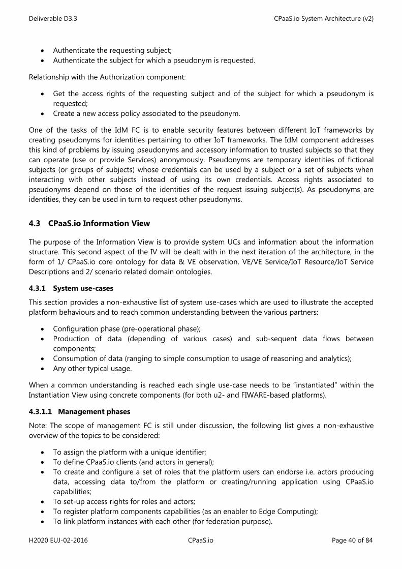
Deliverable D3.3 CPaaS.io System Architecture (v2)
H2020 EUJ-02-2016 CPaaS.io Page 40 of 84
• Authenticate the requesting subject; • Authenticate the subject for which a pseudonym is requested.
Relationship with the Authorization component:
• Get the access rights of the requesting subject and of the subject for which a pseudonym is requested;
• Create a new access policy associated to the pseudonym.
One of the tasks of the IdM FC is to enable security features between different IoT frameworks by creating pseudonyms for identities pertaining to other IoT frameworks. The IdM component addresses this kind of problems by issuing pseudonyms and accessory information to trusted subjects so that they can operate (use or provide Services) anonymously. Pseudonyms are temporary identities of fictional subjects (or groups of subjects) whose credentials can be used by a subject or a set of subjects when interacting with other subjects instead of using its own credentials. Access rights associated to pseudonyms depend on those of the identities of the request issuing subject(s). As pseudonyms are identities, they can be used in turn to request other pseudonyms.
4.3 CPaaS.io Information View
The purpose of the Information View is to provide system UCs and information about the information structure. This second aspect of the IV will be dealt with in the next iteration of the architecture, in the form of 1/ CPaaS.io core ontology for data & VE observation, VE/VE Service/IoT Resource/IoT Service Descriptions and 2/ scenario related domain ontologies.
4.3.1 System use-cases
This section provides a non-exhaustive list of system use-cases which are used to illustrate the accepted platform behaviours and to reach common understanding between the various partners:
• Configuration phase (pre-operational phase); • Production of data (depending of various cases) and sub-sequent data flows between
components; • Consumption of data (ranging to simple consumption to usage of reasoning and analytics); • Any other typical usage.
When a common understanding is reached each single use-case needs to be “instantiated” within the Instantiation View using concrete components (for both u2- and FIWARE-based platforms).
4.3.1.1 Management phases
Note: The scope of management FC is still under discussion, the following list gives a non-exhaustive overview of the topics to be considered:
• To assign the platform with a unique identifier; • To define CPaaS.io clients (and actors in general); • To create and configure a set of roles that the platform users can endorse i.e. actors producing
data, accessing data to/from the platform or creating/running application using CPaaS.io capabilities;
• To set-up access rights for roles and actors; • To register platform components capabilities (as an enabler to Edge Computing); • To link platform instances with each other (for federation purpose).
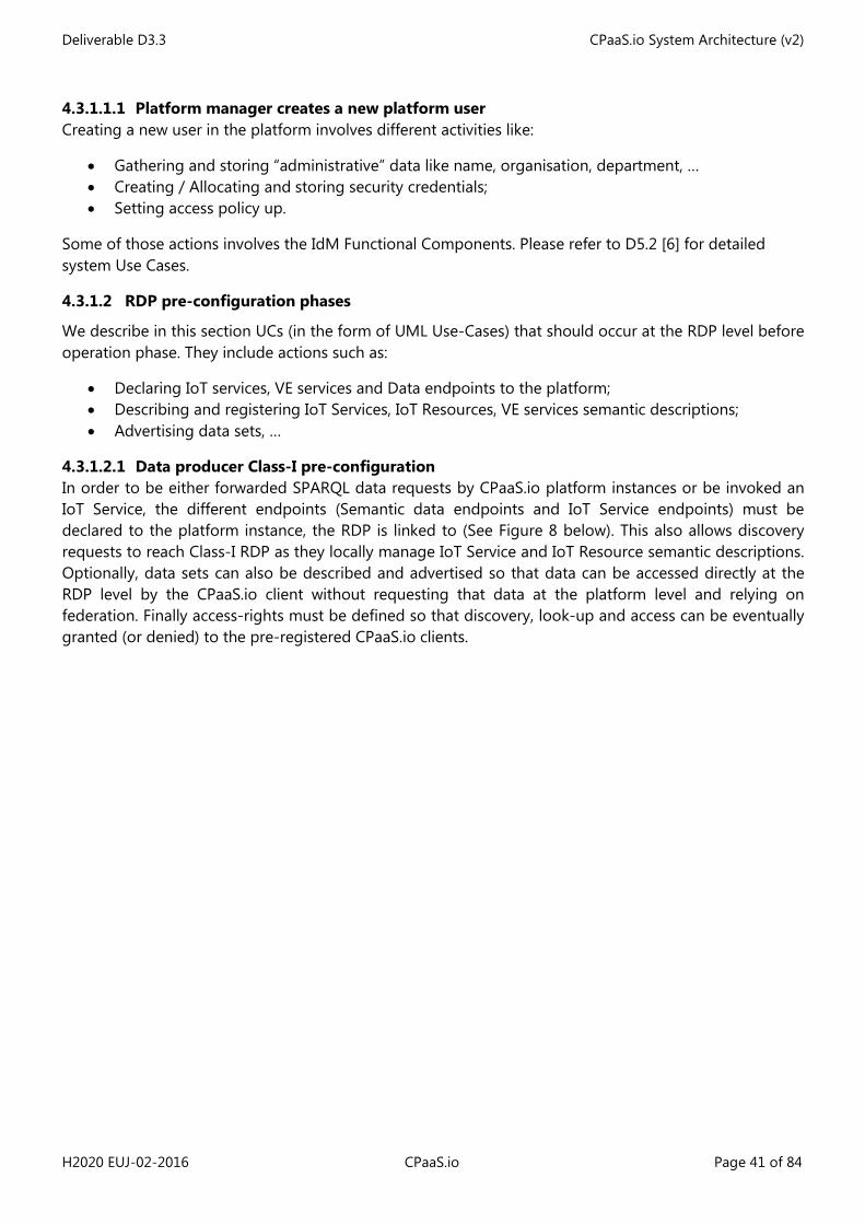
Deliverable D3.3 CPaaS.io System Architecture (v2)
H2020 EUJ-02-2016 CPaaS.io Page 41 of 84
4.3.1.1.1 Platform manager creates a new platform user Creating a new user in the platform involves different activities like:
• Gathering and storing “administrative” data like name, organisation, department, … • Creating / Allocating and storing security credentials; • Setting access policy up.
Some of those actions involves the IdM Functional Components. Please refer to D5.2 [6] for detailed system Use Cases.
4.3.1.2 RDP pre-configuration phases
We describe in this section UCs (in the form of UML Use-Cases) that should occur at the RDP level before operation phase. They include actions such as:
• Declaring IoT services, VE services and Data endpoints to the platform; • Describing and registering IoT Services, IoT Resources, VE services semantic descriptions; • Advertising data sets, …
4.3.1.2.1 Data producer Class-I pre-configuration In order to be either forwarded SPARQL data requests by CPaaS.io platform instances or be invoked an IoT Service, the different endpoints (Semantic data endpoints and IoT Service endpoints) must be declared to the platform instance, the RDP is linked to (See Figure 8 below). This also allows discovery requests to reach Class-I RDP as they locally manage IoT Service and IoT Resource semantic descriptions. Optionally, data sets can also be described and advertised so that data can be accessed directly at the RDP level by the CPaaS.io client without requesting that data at the platform level and relying on federation. Finally access-rights must be defined so that discovery, look-up and access can be eventually granted (or denied) to the pre-registered CPaaS.io clients.
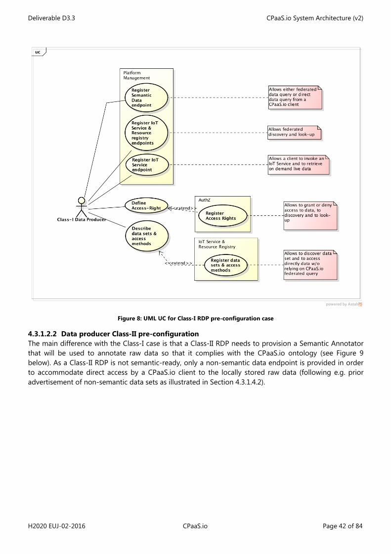
Deliverable D3.3 CPaaS.io System Architecture (v2)
H2020 EUJ-02-2016 CPaaS.io Page 42 of 84
Figure 8: UML UC for Class-I RDP pre-configuration case
4.3.1.2.2 Data producer Class-II pre-configuration The main difference with the Class-I case is that a Class-II RDP needs to provision a Semantic Annotator that will be used to annotate raw data so that it complies with the CPaaS.io ontology (see Figure 9 below). As a Class-II RDP is not semantic-ready, only a non-semantic data endpoint is provided in order to accommodate direct access by a CPaaS.io client to the locally stored raw data (following e.g. prior advertisement of non-semantic data sets as illustrated in Section 4.3.1.4.2).
Deliverable D3.3 CPaaS.io System Architecture (v2)
H2020 EUJ-02-2016 CPaaS.io Page 43 of 84
Figure 9: UML UC for Class-II RDP pre-configuration case
4.3.1.2.3 Data producer Class-III pre-configuration As explained in Section 4.1 RDPs Class-III are infrastructure-less parties that only own IoT Resources. They rely on the CPaaS.io platform for:
• Registering their IoT Resources so that they can be discovered or looked-up; • Serving, registering and managing IoT Services that expose their IoT Service so that they can be
discovered, looked up and invoked (for synchronous live data consumption); • Pulling data from the IoT Resources; • Annotating semantically the data; • Producing the data towards the Semantic Data Repository.
The two first items of this list pertain to a configuration phase that occurs prior to any data production (which is elucidated in Section 4.3.1.4). The UML use-case below (Figure 12) explains in details those actions.
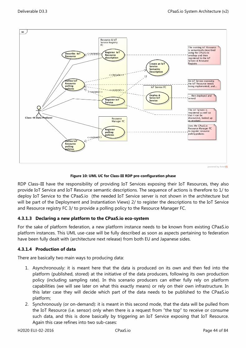
Deliverable D3.3 CPaaS.io System Architecture (v2)
H2020 EUJ-02-2016 CPaaS.io Page 44 of 84
Figure 10: UML UC for Class-III RDP pre-configuration phase
RDP Class–III have the responsibility of providing IoT Services exposing their IoT Resources, they also provide IoT Service and IoT Resource semantic descriptions. The sequence of actions is therefore to 1/ to deploy IoT Service to the CPaaS.io (the needed IoT Service server is not shown in the architecture but will be part of the Deployment and Instantiation Views) 2/ to register the descriptions to the IoT Service and Resource registry FC 3/ to provide a polling policy to the Resource Manager FC.
4.3.1.3 Declaring a new platform to the CPaaS.io eco-system
For the sake of platform federation, a new platform instance needs to be known from existing CPaaS.io platform instances. This UML use-case will be fully described as soon as aspects pertaining to federation have been fully dealt with (architecture next release) from both EU and Japanese sides.
4.3.1.4 Production of data
There are basically two main ways to producing data:
1. Asynchronously: it is meant here that the data is produced on its own and then fed into the platform (published, stored) at the initiative of the data producers, following its own production policy (including sampling rate). In this scenario producers can either fully rely on platform capabilities (we will see later on what this exactly means) or rely on their own infrastructure. In this later case they will decide which part of the data needs to be published to the CPaaS.io platform;
2. Synchronously (or on-demand): it is meant in this second mode, that the data will be pulled from the IoT Resource (i.e. sensor) only when there is a request from “the top” to receive or consume such data, and this is done basically by triggering an IoT Service exposing that IoT Resource. Again this case refines into two sub-cases:
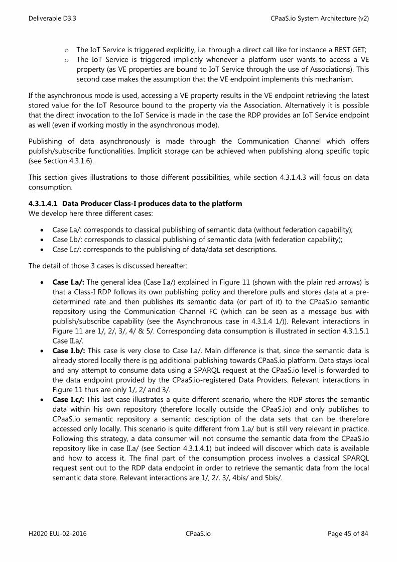
Deliverable D3.3 CPaaS.io System Architecture (v2)
H2020 EUJ-02-2016 CPaaS.io Page 45 of 84
o The IoT Service is triggered explicitly, i.e. through a direct call like for instance a REST GET; o The IoT Service is triggered implicitly whenever a platform user wants to access a VE
property (as VE properties are bound to IoT Service through the use of Associations). This second case makes the assumption that the VE endpoint implements this mechanism.
If the asynchronous mode is used, accessing a VE property results in the VE endpoint retrieving the latest stored value for the IoT Resource bound to the property via the Association. Alternatively it is possible that the direct invocation to the IoT Service is made in the case the RDP provides an IoT Service endpoint as well (even if working mostly in the asynchronous mode).
Publishing of data asynchronously is made through the Communication Channel which offers publish/subscribe functionalities. Implicit storage can be achieved when publishing along specific topic (see Section 4.3.1.6).
This section gives illustrations to those different possibilities, while section 4.3.1.4.3 will focus on data consumption.
4.3.1.4.1 Data Producer Class-I produces data to the platform We develop here three different cases:
• Case I.a/: corresponds to classical publishing of semantic data (without federation capability); • Case I.b/: corresponds to classical publishing of semantic data (with federation capability); • Case I.c/: corresponds to the publishing of data/data set descriptions.
The detail of those 3 cases is discussed hereafter:
• Case I.a/: The general idea (Case I.a/) explained in Figure 11 (shown with the plain red arrows) is that a Class-I RDP follows its own publishing policy and therefore pulls and stores data at a pre-determined rate and then publishes its semantic data (or part of it) to the CPaaS.io semantic repository using the Communication Channel FC (which can be seen as a message bus with publish/subscribe capability (see the Asynchronous case in 4.3.1.4 1/)). Relevant interactions in Figure 11 are 1/, 2/, 3/, 4/ & 5/. Corresponding data consumption is illustrated in section 4.3.1.5.1 Case II.a/.
• Case I.b/: This case is very close to Case I.a/. Main difference is that, since the semantic data is already stored locally there is no additional publishing towards CPaaS.io platform. Data stays local and any attempt to consume data using a SPARQL request at the CPaaS.io level is forwarded to the data endpoint provided by the CPaaS.io-registered Data Providers. Relevant interactions in Figure 11 thus are only 1/, 2/ and 3/.
• Case I.c/: This last case illustrates a quite different scenario, where the RDP stores the semantic data within his own repository (therefore locally outside the CPaaS.io) and only publishes to CPaaS.io semantic repository a semantic description of the data sets that can be therefore accessed only locally. This scenario is quite different from 1.a/ but is still very relevant in practice. Following this strategy, a data consumer will not consume the semantic data from the CPaaS.io repository like in case II.a/ (see Section 4.3.1.4.1) but indeed will discover which data is available and how to access it. The final part of the consumption process involves a classical SPARQL request sent out to the RDP data endpoint in order to retrieve the semantic data from the local semantic data store. Relevant interactions are 1/, 2/, 3/, 4bis/ and 5bis/.
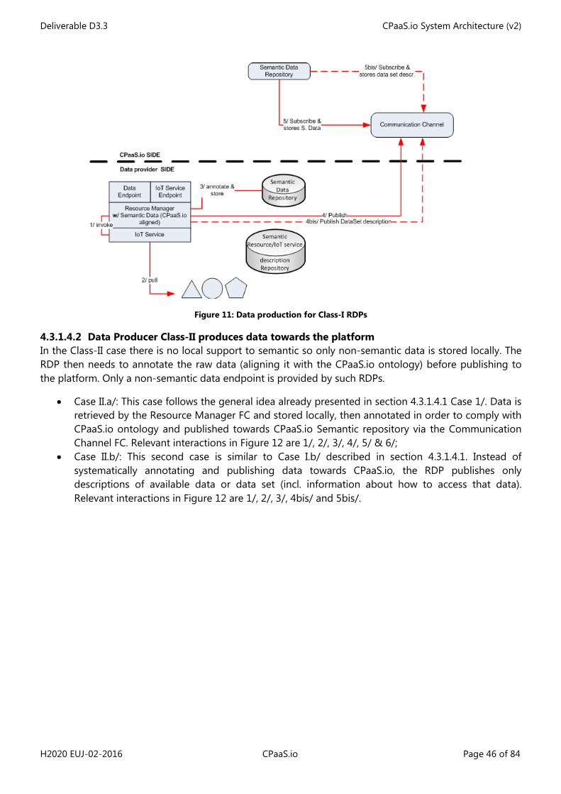
Deliverable D3.3 CPaaS.io System Architecture (v2)
H2020 EUJ-02-2016 CPaaS.io Page 46 of 84
Figure 11: Data production for Class-I RDPs
4.3.1.4.2 Data Producer Class-II produces data towards the platform In the Class-II case there is no local support to semantic so only non-semantic data is stored locally. The RDP then needs to annotate the raw data (aligning it with the CPaaS.io ontology) before publishing to the platform. Only a non-semantic data endpoint is provided by such RDPs.
• Case II.a/: This case follows the general idea already presented in section 4.3.1.4.1 Case 1/. Data is retrieved by the Resource Manager FC and stored locally, then annotated in order to comply with CPaaS.io ontology and published towards CPaaS.io Semantic repository via the Communication Channel FC. Relevant interactions in Figure 12 are 1/, 2/, 3/, 4/, 5/ & 6/;
• Case II.b/: This second case is similar to Case I.b/ described in section 4.3.1.4.1. Instead of systematically annotating and publishing data towards CPaaS.io, the RDP publishes only descriptions of available data or data set (incl. information about how to access that data). Relevant interactions in Figure 12 are 1/, 2/, 3/, 4bis/ and 5bis/.
Deliverable D3.3 CPaaS.io System Architecture (v2)
H2020 EUJ-02-2016 CPaaS.io Page 47 of 84
Figure 12: Data production for Class-II RDP
4.3.1.4.3 Data Producer Class-III produces data towards the platform Since a RDP Class-III is passive, it does not per se push data towards the platform. On the contrary an agent (namely IoT Resource Manager FC) located at the platform side is responsible for polling data from the resources owned but the RDP and pushing it to the platform.
A WEB front-end allows the owner of the IoT Resources to specify a polling policy like for instance a time schedule, sampling rate and topic to be used, would the data be forwarded to the Communication Channel for real-time consumption. Instead of using this channel, the RDP may decide to store it directly within the non-semantic data repository.
4.3.1.4.4 Data Producer Class-IV & V produce data towards the platform Class-IV and –V RDP are yet another two similar classes of passive RDP which are relying on platform agents for polling data and passing it on towards the platform. Like for Class-III RDPs, they rely respectively on the two Live Data Listener & Ingestion (LDLI) and Government Data Listener & Ingestion (GDLI) FCs part of the IoT Service FG. Both FCs are instrumented via either a web front-end page where the nature of data to be retrieved / subscribe to is specified or directly via the FC API (this is the mode used by the ML component).
The LDLI is focussed only on Twitter in its preliminary version. It can retrieve data in two different modes:
• Streaming data: it then subscribes to a tweet feed according to a given list of hash tags and strings and sends to the Communication Channel;
• Historical data: it retrieves in one-go a bunch of social media data and sends it to the Communication Channel or back to the invocating party (e.g. the ML component).
4.3.1.5 Consumption of data
Consumption of data can be done as follows:
• Live data o Invoking an IoT Service, in order to either retrieve annotated current readings from a sensor
resource, or setting a new actuator value;
Deliverable D3.3 CPaaS.io System Architecture (v2)
H2020 EUJ-02-2016 CPaaS.io Page 48 of 84
o Invoking a VE-service in order to get directly current value of VE properties; • Historical data (stored data)
o Retrieving VE-level observations or annotated sensor historical data using SPARQL queries.
4.3.1.5.1 CPaaS.io client consumes data originating from RDP Class-I Data consumption from Class-I RDP offers 5 alternative methods:
• Case I.a/: Data previously published by a Class-I RDP can be consumed from the CPaaS.io semantic repository via a SPARQL request (this corresponds to the case where the RDP either duplicates all its semantic data or publishes surveys or part of its semantic data within CPaaS.io repository) to the CPaaS.io semantic data repository;
• Case I.b/: Alternatively if the RDP local platform has registered its data endpoint to the CPaaS.io, the federation capabilities of the platform, makes sure that any incoming SPARQL request is forwarded to the RDP. The request is therefore answered by the RDP itself;
• Case I.c/: In this last case, the data endpoint of the RDP is accessed directly by the CPaaS.io client as means to access the data/data set and data/data set descriptions were previously advertised to the platform and therefore could be discovered by the client prior to data consumption (See Case I.c/ in Section 4.3.1.4.1);
• Case I.d/: As far as live data is concerned, the CPaaS.io client can invoke directly an IoT Service (following discovery and resolution) via the IoT Service endpoint and therefore being returned the current annotated value;
• Case I.e/: Subscribing to the Communication Channel in order to receive automatically the flow of produced data.
4.3.1.5.2 CPaaS.io client consumes data originating from RDP Class-II Data consumption from Class-I RDP offers 4 alternative methods:
• Case II.a/: like in Case I.a/ above the historical data can be accessed from the CPaaS.io Semantic data Repository FC via a SPARQL request sent to the Semantic Data Repository SPARQL data endpoint;
• Case II.b/: Corresponding to Case I.b/ above, {historical data/data set} has been previously advertised and therefore can be accessed directly by the CPaaS.io client from the RDP SPARQL data endpoint, without involving the CPaaS.io platform (apart for the discovery phase);
• Case II.c/: Subscribing to the Communication Channel in order to receive automatically the flow of produced data;
• Case ii.d/: As far as live data is concerned, if the CPaaS.io client is not satisfied with the sampling rate implemented by the RDP, it can also invoke directly an IoT Service (following discovery and resolution) via the IoT Service endpoint and therefore being returned the current annotated value in near real time.
4.3.1.5.3 CPassS.io client consumes data originating from RDP Class-III Data consumption from Class-III RDP is achieved in 3 ways:
• Using SPARQL request at the CPaaS.io platform level in order to query historical data from the Semantic Data Repository;
• Invoking IoT Services exposing the RDP resources via the IoT Service server at the platform level; • Subscribing to the Communication Channel for live data consumption.
4.3.1.5.4 CPassS.io client consumes data originating from RDP Class-IV or Class-V Data consumption from Class-IV orClass-V RDPs is achieved in 3 ways:
Deliverable D3.3 CPaaS.io System Architecture (v2)
H2020 EUJ-02-2016 CPaaS.io Page 49 of 84
• Using SPARQL request at the CPaaS.io platform level in order to query historical data from the Semantic Data Repository;
• Invoking the API from (respectively) the LDLI and GDLI FCs; • Subscribing to the Communication Channel for live data consumption.
4.3.1.6 Storage of Data
Storage of IoT data or VE data can be achieved explicitly using the two Semantic/Non-semantic Data Repository FC and Semantic/Non-semantic VE Data Repository FC APIs or implicitly when publishing the data to the Communication Channel along a pre-determined topic.
By default the four data repositories (VE-level and IoT-level) are listening the Communication Channel and storing everything coming along pre-determined topics they are assigned to.
4.3.2 CPaaS.io ontologies and internal formats
Ontologies will be used for describing PEs (via the modelling of VE properties), for metadata like quality information, and for linking of data sets from different providers. In particular for the federation of implementation platforms between Europe and Japan, as the implementation platforms in the two regions provide the data in different forms (NGSI in Europe, ucR in Japan).
As mentioned in Deliverable D6.1 [7], the project will be implementing the W3C proposed recommendation on “Data on the Web Best Practices”7 and make use of existing ontologies and evolving standards. At the time of writing it has however not been decided yet which concrete ontologies and vocabularies will be used.
A second round of discussions discarded the FIESTA-IoT ontology due to some doubt about its sustainability. In the meanwhile a second version of SSN including actuation has been released by the W3C consortium (Spring 2017). It is still lacking some concepts and relations but we are confident it could be extended in order to cover those missing ones, using for instance fragments of OWL-S or IoT-A ontologies (for covering the descriptions of IoT-services and others like e.g. analytics-as-a-service).
We envision that the main usages for the CPaaS.io ontology will be:
• To model/describe entities of interest (PEs) and their virtual counterparts, the VEs (classes and instances);
• To model/describe IoT Resources (i.e. Sensors and Actuators); • To model/describe Sensor and VE observations (only sensor observations are covered by SSN2); • To model/describe Actuation actions and VE actions; • To model/describe Services profiles (IoT Services and general purpose services e.g. analytics); • To describe data-sets (either stored locally or within the platform); • To model Domain-related concepts and relations.
The full specification of the CPaaS.io ontology will be provided during Year 2 of the project, and documented partly in D3.5 and fully in WP6 deliverables.
For more details, please refer to Deliverable D6.1 [7] and forthcoming D6.3 [8].
7 https://www.w3.org/TR/dwbp/
Deliverable D3.3 CPaaS.io System Architecture (v2)
H2020 EUJ-02-2016 CPaaS.io Page 50 of 84
5 Perspectives
This section provides a preliminary description of the CPaaS.io perspectives and starts sketching strategies for reaching the identified targeted properties/qualities of the CPaaS.io platform. The objective here is to refine strategies and find synchronisation points between the Japanese and European approaches so that interoperability can be eventually ensured. See Section 2.1.5 for an introduction to Perspectives.
5.1 Security
5.1.1 Policy Based Authorization for Access Control
Description: The Access Control module within CPaaS.io is responsible for making authorization decisions based on access control policies. These polices define the permissions that a subject (smart object or user) has over certain target resources (e.g. IoT service). Thus, the policies specify which particular actions that subjects or groups are allowed to perform over a target resource under certain conditions. These conditions usually refer to the context information provided by the context manager module. In this regard, the eXtensible Access Control Markup Language (XACML) [25] policy language will be adopted in CPaaS.io to deal with authorization policies.
Additionally, it is desirable to employ access control solutions specially designed for IoT scenarios. Recently, the capability-based access control model (CapBAC) has been postulated as a realistic and promising approach to be deployed on IoT scenarios. In this sense, the authorization component is able to perform capability-based access control based on the mechanism presented in [26].
In a typical CapBAC scenario, an entity (subject) tries to access a resource of another entity (target). Usually, a third party (issuer) generates a token for the subject specifying which privileges it has. Thus, when the subject attempts to access a resource hosted in the target, it attaches the token which was generated by the issuer. Then, the target evaluates the token granting or denying access to the resource. Therefore, a subject which wishes to get access to certain information from a target, requires sending the token together with the request. Thus, the target that receives such token already knows the privileges that the subject has and a local Policy Decision Point (PDP) only needs to verify the capability token is valid. This simplifies the access control mechanism, and it is a relevant feature in scenarios with resource-constrained devices since complex access control policies are not required to be deployed on constrained end-devices.
Additionally, the token must be tamper-proof and unequivocally identified in order to be considered in a real environment. Therefore, it is necessary to consider suitable cryptographic mechanisms to be used even on resource-constrained devices which enable an end-to-end secure access control mechanism. Moreover, given its high level of flexibility, CapBAC could be also extended to consider contextual conditions related to parameters which are locally sensed by end-devices. Also, this model could be complemented by other access control models by providing automated tools to infer the privileges to be embedded into the token.
On the other hand, this component is also responsible for providing access control to the information broadcast in a shared media allowing only the consumers with the right credentials to gain access to such information.
To do so, this component uses CP-ABE [35], an encryption schema that ciphers information under a certain policy of attributes, and the keys of the users are associated with sets of attributes. This enables
Deliverable D3.3 CPaaS.io System Architecture (v2)
H2020 EUJ-02-2016 CPaaS.io Page 51 of 84
dissemination of information using different information sharing models where the producer of the information is always on control of how the information is accessed.
CP-ABE is considered, because IoT Systems need not only effective ways of coping with security issues but also efficient ones. In this sense, although the classic security schemes such as Secret Key Cryptography (SKC) and Private Key Cryptography (PKC) provide proven security primitives, they may not be suitable for distributed systems as IoT. The use of CP-ABE is an interesting improvement to the other ciphering schemes. With CP-ABE, the information can only be ciphered with the policies previously defined, and all users whose keys satisfy the policy are able to decipher the information. This not only saves resources, but might also be well related with the attribute-based nature of XACML, giving consistency to the security functionality.
5.1.2 Authentication
Description: Authentication ensures that an identity of a subject (user or smart object) is valid, i.e., that the subject is indeed who it or what it claims to be. The authentication module enables authenticating users and smart objects based on the provided credentials. The credential can be in form of login/password, shared key, digital certificate.
Traditional authentication mechanisms based on for instance login-password or electronic IDs have been already solved in by other projects and solutions. CPaaS.io focuses on alternative and more sophisticated ways of performing authentication ensuring, at the same time, privacy and minimal disclosure of attributes. Thus, this kind of alternative privacy-preserving way of authentication using anonymous credential system is handled in CPaaS.io framework by the Identity Management Component.
The IdM is able to verify anonymous credential and then, in case the identity is proved, the IdM interacts with the authentication module which is the one that actually delivers authentication assertion to be used during a transaction.
5.1.3 Privacy Preserving Identity Management
Description: The Identity Management (IdM) module is responsible for managing the identities of smart objects and users. The module is able to take into account privacy concerns to manage subjects’ credentials (from users or smart objects), in a privacy-preserving way relying on anonymous credential systems. It is able to endow subjects with mechanisms to ensure anonymity, which is done mainly issuing pseudonyms and proof of credentials to minimal personal data disclosure.
The IdM system is responsible for managing and storing the credentials, which are used by subjects to request information from an IoT services. The IdM allows users to obtain the proper credentials that can be use afterwards to derive proofs of identity to be presented to a Verifier (e.g., IoT Service provider) in order to prove the identity condition while disclosing the minimum amount of private information.
The component is envisioned as endowed with a cryptographic engine like Idemix [27] responsible for low level cryptographic operations required by the anonymous credential system.
5.1.4 Extension to Key Exchange and Management
Description: The Key Exchange and Management (KEM) component assists peers involved in a communication in the process of establishing a security context, like for instance, setting up tunnels for a security communication. It involves cryptographic key exchange and provides interoperability between the peers in order to reach an agreement regarding the security functions to use for the communication. This component is also in charge of storing and generating the cryptographic keys.
The Group Manager module as an extension of the KEM, enables sharing information in a secure and
Deliverable D3.3 CPaaS.io System Architecture (v2)
H2020 EUJ-02-2016 CPaaS.io Page 52 of 84
private way, with those groups of entities that satisfy certain particular sets of identity attributes values. These particular sets of attributes are represented by attribute sharing policies, which are influenced by context information where the data sharing is being performed.
This module is envisioned to manage dynamic sharing groups. To this aim, the group manager makes use of attribute based encryption mechanism, namely the Ciphertext-Policy Attribute-Base Encryption (CP-ABE) scheme [28]. With this scheme, data to be shared within a group is encrypted under a policy of attributes, while keys of participants are associated with sets of attributes. Only those target users that satisfy particular identity attributes (those given in the policy) possess the cipher keys to decrypt the data. In this way, a data producer can exert full control over how the information is disseminated to other entities, while a consumer’s identity can be intuitively reflected by a certain private key.
5.2 Semantic Interoperability
Information Model
Description: The FIWARE focuses on a common data model and powerful interfaces for searching and finding information. FIWARE is using the OMA Next Generation Service Interface (NGSI) data model as the common information model of IoT-based systems and the protocol for communication. We describe the NGSI9 and NGIS10 below.
NGSI9 is used to manage the availability of context entity. A system component can register the availability of context information, and later on the other system component can issue either discover or subscribe messages to find out the registered new context information.
NGSI10 is used to enable the context data transfer between data producers and data consumers. NGSI10 has query, update, subscribe and notify context operations for providing context values. A context broker is necessary for establishing data flow between different resources as well as consumers or providers.
5.3 Performance
Service Orchestrator
Description: The Service Orchestrator module is responsible for generating processing task instances and assigning them to proper resources (e.g., edge or cloud nodes) for task deployment, based on the topology defined by developers, the current system status, and also some parameters (e.g., the scope of data sources) given by the operator on the fly. Meanwhile, the Service Orchestrator is managing all task instances over the resources at the global level.
Service orchestrator allows leveraging edge for more efficiency and higher performance in computing and communication. Leveraging edge computing with Service Orchestrator allows significant bandwidth reductions, especially for scenarios such as input streams (e.g., video streams captured by cameras) are filtered or even analysed on the edge and only the filtered values or analytical results are sent to cloud as opposed to sending the raw data as it is.
Deliverable D3.3 CPaaS.io System Architecture (v2)
H2020 EUJ-02-2016 CPaaS.io Page 53 of 84
5.4 Scalability
Federation Agent
Description: Federation agent of the IoT Broker provides capability of forwarding data from one IoT Broker to another with hierarchical or mash-up topologies. For instance, one deployment in a certain area using an IoT Broker can be accessed by another deployment with another IoT Broker. Hence, Federation Agent separates IoT data in different domains and enhances the privacy by giving control of the data access to the IoT domain administrators.
IoT Broker federation allows local deployments to be handled by a local IoT Broker and multiple IoT Brokers can access data from each other when necessary. Moreover, it may also allow deployments from different domains in the same region (e.g., a smart city with multiple business domains) having different IoT Brokers. Compared to the centralized context brokering approach where there is a context broker in the cloud which collects and manages all information, using Federation Agent is more scalable and distributed approach which is suitable for IoT deployments.
6 Instantiation views
6.1 U2-based platform Instantiation View
The TRON Project, since its inception in 1984, has been aiming at the realization of Highly Functionally Distributed System (HFDS) where any objects worth connected in our surroundings will be embedded with computers and work in a collaborative manner to offer better service to human users. The concept of HFDS has been realized partially by the concept of the IoT and/or ubiquitous computing. In a sense, the world has finally caught up with the project. So far the project has attempted to realize HFDS by developing technological components that would be necessary such as node devices, identification infrastructure, information distribution infrastructure, etc. We are now at the stage when we can combine the components to build a system as a whole and fill in the details since the component technologies have matured.
6.1.1 Description of u2 Functional Components
6.1.1.1 Pre-requisites
In this short section we introduce some concepts which are at the centre of the u2 technology.
6.1.1.1.1 ucode To identify individual objects, spaces, and concepts in the real world, unique identifiers are assigned to respective objects, spaces and concepts that we wish to identify. This model is called a ucode model. The target in the real world to be identified in the ucode model is called an "entity,” and the unique identifier assigned for identifying the entity is called a ucode.
The entity consists of objects, places, and concepts. "Objects" in the ucode model include tangible objects such as industrial products and agricultural crops, and intangible objects such as content and programs. "Places" include features in the real world such as roads and buildings and more detailed smaller components in the real world such as rooms and corridors. "Concepts" include the relationships between "objects" and "places" and the information which can be the real-world context. In a nutshell, the entity is a target to be identified among objects, places, or concepts in the real world, and the identifier to identify the entity is a ucode.
Deliverable D3.3 CPaaS.io System Architecture (v2)
H2020 EUJ-02-2016 CPaaS.io Page 54 of 84
6.1.1.1.2 ucR: ucode Relation ucR: u2 architecture represents the real-world context by modeling the relation on a real-world entity as a relational representation among ucodes allocated to entities or between the ucode and atom , which is a value such as a string, a number or a date. This representation model is called a ucode Relation model (ucR model). When a relationship is represented by ucR model, it is called a Relation.
ucR Unit: The basic unit of the ucR model consists of two ucodes or a ucode and atom, and their relationships. Moreover, the respective relationships between the two are provided with a logical ucode called a relation ucode. This basic unit consisting of the above triplet is called a ucode relation unit (ucR unit). When this triplet is set in a sentence where the relationships are represented as the predicate, the ucode as the subject is called a subject ucode, and the ucode as the predicate which is a relation part is called a relation ucode, and the ucode as the object or complement is called an object ucode. The atom can be substituted for the object ucode. For example, in a description, "R of S is O" or "there is a relation R between S and O," S refers to the subject ucode, R to the relation ucode, and O to the object ucode or atom. When it is not necessary to uniquely identify any of the three elements comprising a ucR unit, their relevant parts can be left blank.
ucR Graph: The information and context about an entity are represented by combining relations among multiple entities. For example, for information on an entity indicating a “stuffed cabbage,” pieces of information such as its recipe, a cabbage as ingredients, and a production area of the cabbage are combined. To represent such information, ucR units are combined, and a digraph where multiple ucodes and atoms are connecting by relation ucodes is built. The digraph generated based on the above method is called a ucode Relation graph (ucR graph). More specifically, the ucR graph is a massive graph structure, in which ucodes are connected by relations and pieces of information described as atoms are associated with each ucode.
6.1.1.2 ucode Resolution Component
The wide-area distributed database which manages ucR graphs is called a ucode Relation database. The ucR database comprehensively manages information on the relations among multiple ucodes in addition to the content such as information services associated with individual entities to which ucodes are assigned. The ucR database is basically an open database which anyone can use to reference or register information, but it can also implement an access control.
u2 architecture does not specify the internal configuration of the ucR database. However, the ucR database must provide an interface for ucode resolution explained in the following section.
When a user physically accesses an entity in the real world, u2 architecture identifies the information appropriate to the situation from the ucR database, based on the ucode assigned to the entity. This process is called ucode resolution. Moreover, the information associated with ucodes, namely, the ucR graph is registered in the ucR database. The protocol for accessing the ucR database in this manner is called ucode Resolution Protocol (ucodeRP).
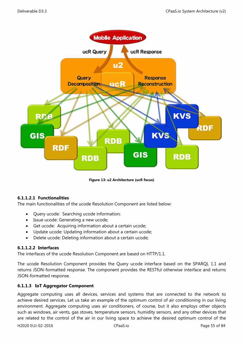
Deliverable D3.3 CPaaS.io System Architecture (v2)
H2020 EUJ-02-2016 CPaaS.io Page 55 of 84
Figure 13: u2 Architecture (ucR focus)
6.1.1.2.1 Functionalities The main functionalities of the ucode Resolution Component are listed below:
• Query ucode: Searching ucode information; • Issue ucode: Generating a new ucode; • Get ucode: Acquiring information about a certain ucode; • Update ucode: Updating information about a certain ucode; • Delete ucode: Deleting information about a certain ucode;
6.1.1.2.2 Interfaces The interfaces of the ucode Resolution Component are based on HTTP/1.1.
The ucode Resolution Component provides the Query ucode interface based on the SPARQL 1.1 and returns JSON-formatted response. The component provides the RESTful otherwise interface and returns JSON-formatted response.
6.1.1.3 IoT Aggregator Component
Aggregate computing uses all devices, services and systems that are connected to the network to achieve desired services. Let us take an example of the optimum control of air conditioning in our living environment. Aggregate computing uses air conditioners, of course, but it also employs other objects such as windows, air vents, gas stoves, temperature sensors, humidity sensors, and any other devices that are related to the control of the air in our living space to achieve the desired optimum control of the
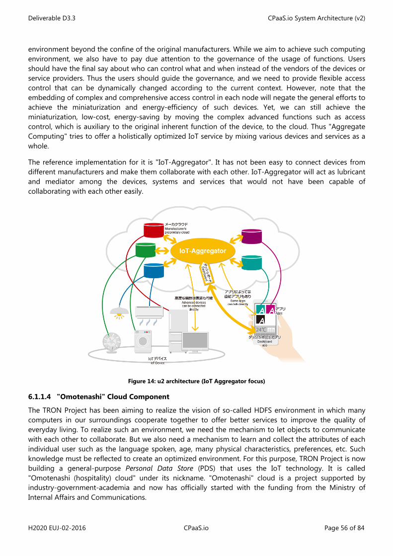
Deliverable D3.3 CPaaS.io System Architecture (v2)
H2020 EUJ-02-2016 CPaaS.io Page 56 of 84
environment beyond the confine of the original manufacturers. While we aim to achieve such computing environment, we also have to pay due attention to the governance of the usage of functions. Users should have the final say about who can control what and when instead of the vendors of the devices or service providers. Thus the users should guide the governance, and we need to provide flexible access control that can be dynamically changed according to the current context. However, note that the embedding of complex and comprehensive access control in each node will negate the general efforts to achieve the miniaturization and energy-efficiency of such devices. Yet, we can still achieve the miniaturization, low-cost, energy-saving by moving the complex advanced functions such as access control, which is auxiliary to the original inherent function of the device, to the cloud. Thus "Aggregate Computing" tries to offer a holistically optimized IoT service by mixing various devices and services as a whole.
The reference implementation for it is "IoT-Aggregator". It has not been easy to connect devices from different manufacturers and make them collaborate with each other. IoT-Aggregator will act as lubricant and mediator among the devices, systems and services that would not have been capable of collaborating with each other easily.
Figure 14: u2 architecture (IoT Aggregator focus)
6.1.1.4 "Omotenashi" Cloud Component
The TRON Project has been aiming to realize the vision of so-called HDFS environment in which many computers in our surroundings cooperate together to offer better services to improve the quality of everyday living. To realize such an environment, we need the mechanism to let objects to communicate with each other to collaborate. But we also need a mechanism to learn and collect the attributes of each individual user such as the language spoken, age, many physical characteristics, preferences, etc. Such knowledge must be reflected to create an optimized environment. For this purpose, TRON Project is now building a general-purpose Personal Data Store (PDS) that uses the IoT technology. It is called "Omotenashi (hospitality) cloud" under its nickname. "Omotenashi" cloud is a project supported by industry-government-academia and now has officially started with the funding from the Ministry of Internal Affairs and Communications.
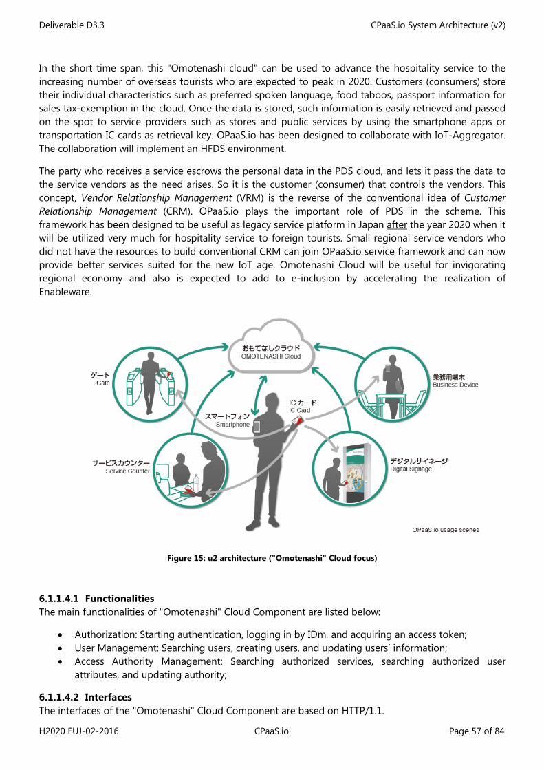
Deliverable D3.3 CPaaS.io System Architecture (v2)
H2020 EUJ-02-2016 CPaaS.io Page 57 of 84
In the short time span, this "Omotenashi cloud" can be used to advance the hospitality service to the increasing number of overseas tourists who are expected to peak in 2020. Customers (consumers) store their individual characteristics such as preferred spoken language, food taboos, passport information for sales tax-exemption in the cloud. Once the data is stored, such information is easily retrieved and passed on the spot to service providers such as stores and public services by using the smartphone apps or transportation IC cards as retrieval key. OPaaS.io has been designed to collaborate with IoT-Aggregator. The collaboration will implement an HFDS environment.
The party who receives a service escrows the personal data in the PDS cloud, and lets it pass the data to the service vendors as the need arises. So it is the customer (consumer) that controls the vendors. This concept, Vendor Relationship Management (VRM) is the reverse of the conventional idea of Customer Relationship Management (CRM). OPaaS.io plays the important role of PDS in the scheme. This framework has been designed to be useful as legacy service platform in Japan after the year 2020 when it will be utilized very much for hospitality service to foreign tourists. Small regional service vendors who did not have the resources to build conventional CRM can join OPaaS.io service framework and can now provide better services suited for the new IoT age. Omotenashi Cloud will be useful for invigorating regional economy and also is expected to add to e-inclusion by accelerating the realization of Enableware.
Figure 15: u2 architecture ("Omotenashi" Cloud focus)
6.1.1.4.1 Functionalities The main functionalities of "Omotenashi" Cloud Component are listed below:
• Authorization: Starting authentication, logging in by IDm, and acquiring an access token; • User Management: Searching users, creating users, and updating users’ information; • Access Authority Management: Searching authorized services, searching authorized user
attributes, and updating authority;
6.1.1.4.2 Interfaces The interfaces of the "Omotenashi" Cloud Component are based on HTTP/1.1.
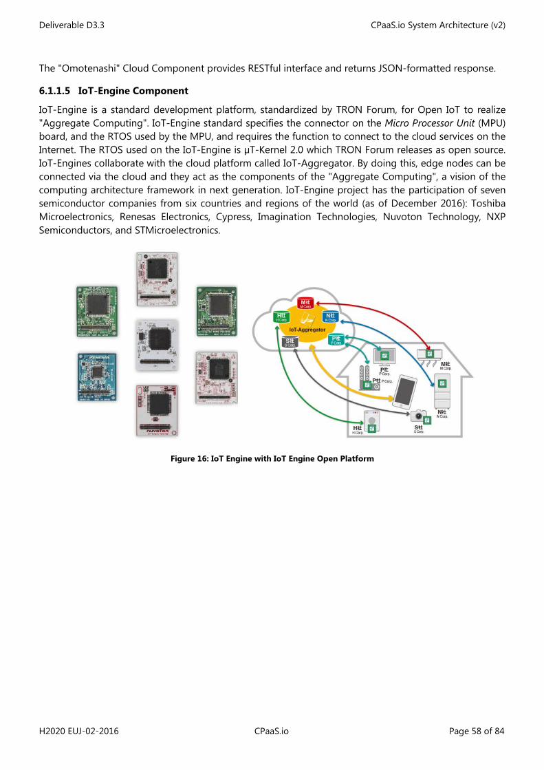
Deliverable D3.3 CPaaS.io System Architecture (v2)
H2020 EUJ-02-2016 CPaaS.io Page 58 of 84
The "Omotenashi" Cloud Component provides RESTful interface and returns JSON-formatted response.
6.1.1.5 IoT-Engine Component
IoT-Engine is a standard development platform, standardized by TRON Forum, for Open IoT to realize "Aggregate Computing". IoT-Engine standard specifies the connector on the Micro Processor Unit (MPU) board, and the RTOS used by the MPU, and requires the function to connect to the cloud services on the Internet. The RTOS used on the IoT-Engine is µT-Kernel 2.0 which TRON Forum releases as open source. IoT-Engines collaborate with the cloud platform called IoT-Aggregator. By doing this, edge nodes can be connected via the cloud and they act as the components of the "Aggregate Computing", a vision of the computing architecture framework in next generation. IoT-Engine project has the participation of seven semiconductor companies from six countries and regions of the world (as of December 2016): Toshiba Microelectronics, Renesas Electronics, Cypress, Imagination Technologies, Nuvoton Technology, NXP Semiconductors, and STMicroelectronics.
Figure 16: IoT Engine with IoT Engine Open Platform
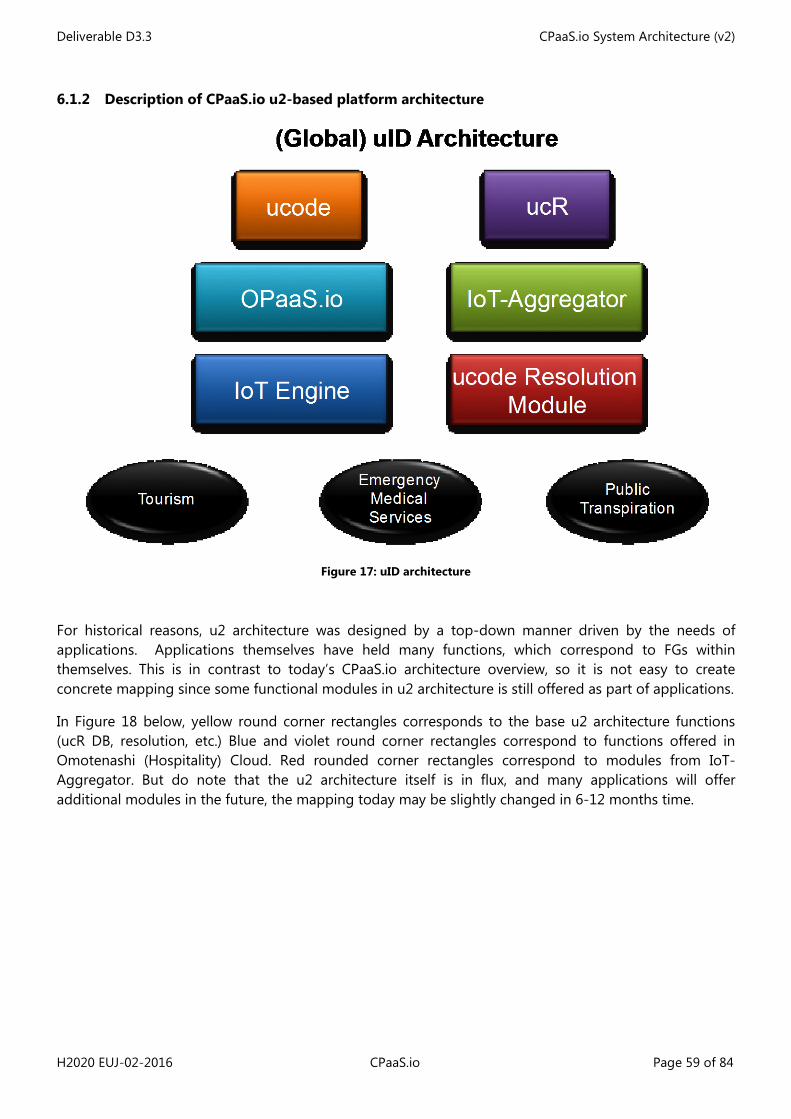
Deliverable D3.3 CPaaS.io System Architecture (v2)
H2020 EUJ-02-2016 CPaaS.io Page 59 of 84
6.1.2 Description of CPaaS.io u2-based platform architecture
Figure 17: uID architecture
For historical reasons, u2 architecture was designed by a top-down manner driven by the needs of applications. Applications themselves have held many functions, which correspond to FGs within themselves. This is in contrast to today’s CPaaS.io architecture overview, so it is not easy to create concrete mapping since some functional modules in u2 architecture is still offered as part of applications.
In Figure 18 below, yellow round corner rectangles corresponds to the base u2 architecture functions (ucR DB, resolution, etc.) Blue and violet round corner rectangles correspond to functions offered in Omotenashi (Hospitality) Cloud. Red rounded corner rectangles correspond to modules from IoT-Aggregator. But do note that the u2 architecture itself is in flux, and many applications will offer additional modules in the future, the mapping today may be slightly changed in 6-12 months time.
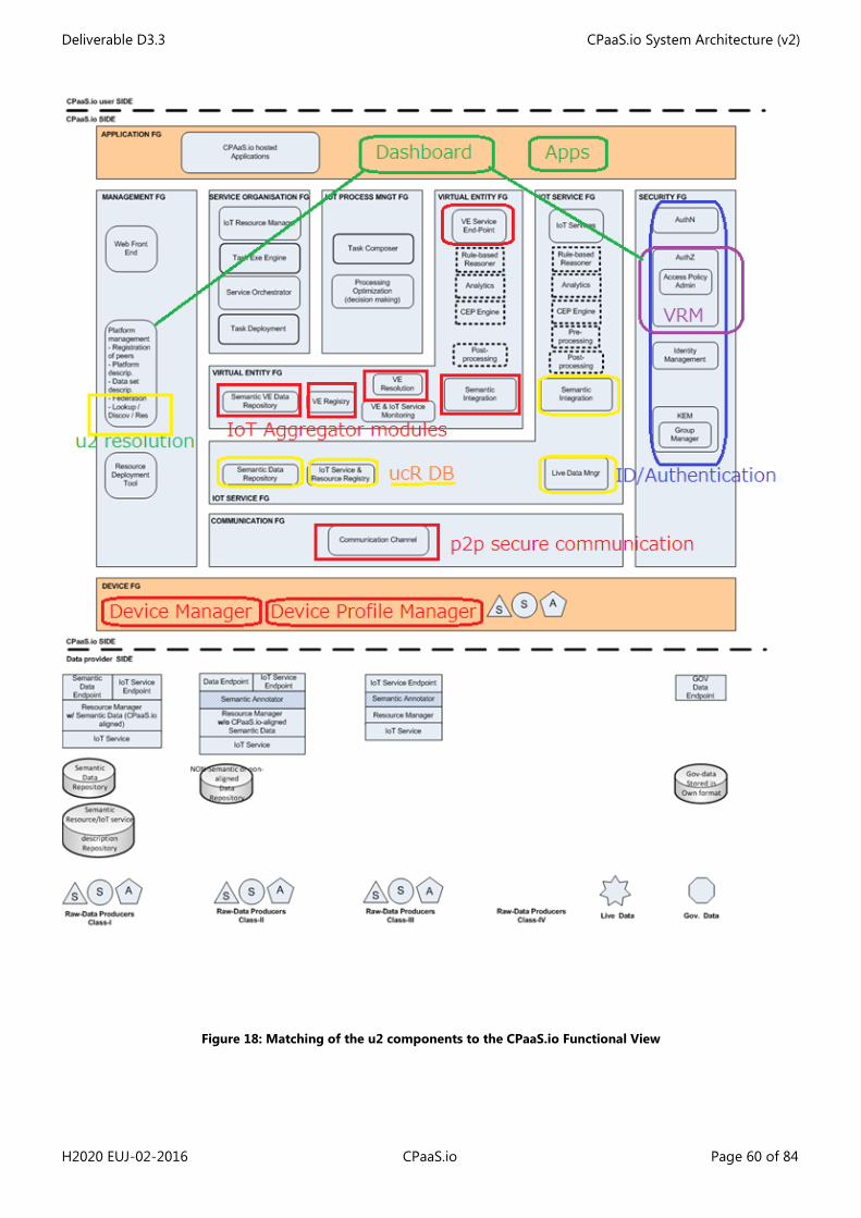
Deliverable D3.3 CPaaS.io System Architecture (v2)
H2020 EUJ-02-2016 CPaaS.io Page 60 of 84
Figure 18: Matching of the u2 components to the CPaaS.io Functional View
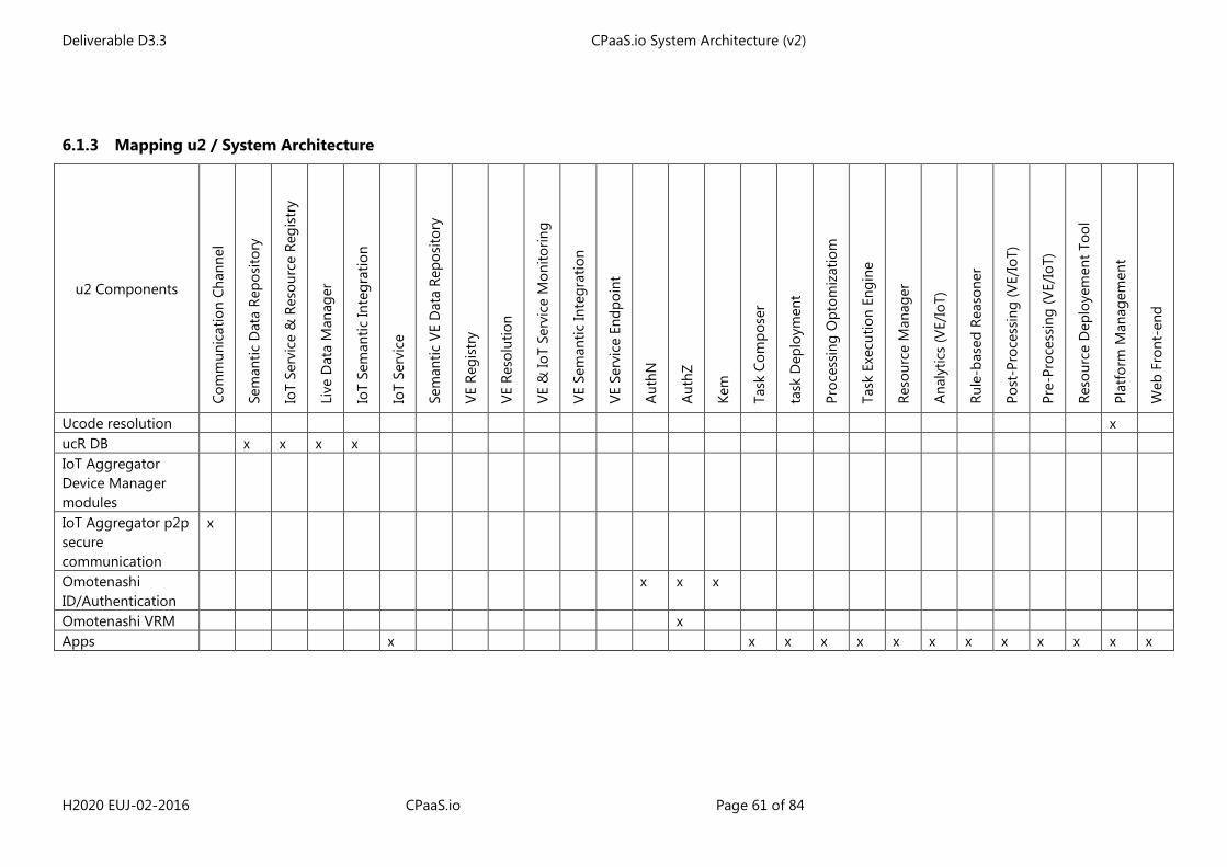
Deliverable D3.3 CPaaS.io System Architecture (v2)
H2020 EUJ-02-2016 CPaaS.io Page 61 of 84
6.1.3 Mapping u2 / System Architecture
u2 Components
Com
mun
icat
ion
Chan
nel
Sem
antic
Dat
a Re
posi
tory
IoT
Serv
ice
& R
esou
rce
Regi
stry
Live
Dat
a M
anag
er
IoT
Sem
antic
Inte
grat
ion
IoT
Serv
ice
Sem
antic
VE
Dat
a Re
posi
tory
VE R
egis
try
VE R
esol
utio
n
VE &
IoT
Serv
ice
Mon
itorin
g
VE S
eman
tic In
tegr
atio
n
VE S
ervi
ce E
ndpo
int
Aut
hN
Aut
hZ
Kem
Task
Com
pose
r
task
Dep
loym
ent
Proc
essi
ng O
ptom
izat
iom
Task
Exe
cutio
n En
gine
Reso
urce
Man
ager
Ana
lytic
s (V
E/Io
T)
Rule
-bas
ed R
easo
ner
Post
-Pro
cess
ing
(VE/
IoT)
Pre-
Proc
essi
ng (V
E/Io
T)
Reso
urce
Dep
loye
men
t Too
l
Plat
form
Man
agem
ent
Web
Fro
nt-e
nd
Ucode resolution x ucR DB x x x x IoT Aggregator Device Manager modules
IoT Aggregator p2p secure communication
x
Omotenashi ID/Authentication
x x x
Omotenashi VRM x Apps x x x x x x x x x x x x x
Deliverable D3.3 CPaaS.io System Architecture (v2)
H2020 EUJ-02-2016 CPaaS.io Page 62 of 84
6.2 FIWARE-based platform Instantiation View
6.2.1 Description of FCs used in the FIWARE-based platform
In this short section let us introduce components which are at the centre of the FIWARE IoT Chapter as well as some components from the European side coming from previous or ongoing EU projects (e.g. KAT Toolkit or FIESTA-IOT IoT Registry).
6.2.1.1 IoT Broker
The IoT Broker is specified as a lightweight and scalable middleware component that separates IoT applications from the underlying device installations. The IoT Broker implementation available through the FIWARE Catalogue is the reference implementation of this Generic Enabler. This implementation satisfies all properties described in the specification of the Generic Enabler. The main features of the IoT Broker are:
• Offering a single point of contact to the user, hiding the complexity of the multi-provider nature of the Internet of Things.
• Collecting and aggregating information about thousands of real-world objects on behalf of the user.
• Provide means to assemble lower-level device information (device-centric access) into higher-level Thing information (information-centric access).
IoT Broker is integrated with three other components: IoT Discovery (ConfMan), IoT Knowledge Server, and FIWARE (Orion) Context Broker.
6.2.1.1.1 Functionalities The main functionalities of the IoT Broker are listed below. Detailed information regarding some of the standard functionalities can be accessed in the specification document of IoT Broker [30].
• Context query: Accessing context information (for data consumers); • Context subscription: Subscribing for a change or update for a context; • Context subscription update: Modifying an existing subscription; • Context notification: IoT Broker sending notifications to the subscribers; • Context data push: Context update from data providers.
Other than these basic context management functionalities, IoT Broker provides access to historical data (via its historical agent functionality), allows geo-scoped queries, federation (via federation agent), and scalability (having multiple server instances).
6.2.1.1.2 Interfaces The main aspects of the IoT Broker are listed below. Detailed information regarding the interface can be found in the interface specification for NGSI-10 [32].
The IoT Broker is implemented based on the FIWARE OMA NGSI 10 interface and it provides a RESTful API via HTTP. The details about the NGSI-10 interface can be found in [33]. The purpose of the NGSI-10 interface is to exchange context information. There are three main interactions types:
1. One-time queries for context information (Context query); 2. Subscriptions for context information updates (Context subscription) / Notifications base on the
subscriptions; 3. Unsolicited updates (invoked by data providers).
Deliverable D3.3 CPaaS.io System Architecture (v2)
H2020 EUJ-02-2016 CPaaS.io Page 63 of 84
The IoT Broker is a RESTful web service supporting HTTP/1.1 with JSON or XML data serialization formats.
Some of the operations of NGSI 10 for exchanging context information are listed as follows: queryContext, contextEntities, contextEntityTypes, subscribeContext, unsubscribeContext, contextSubscriptions, updateContext, updateContextSubscription.
6.2.1.2 ConfMan
The NEC Configuration Management or NEC ConfMan is an implementation of the FIWARE IoT Discovery Generic Enabler. This implementation is specifically designed to interwork with the IoT Broker GE FIWARE reference implementation, serving as the registry of FIWARE NGSI context providers. The detailed information about the IoT Discovery GE can be found in [31].
ConfMan is responsible for discovering the availability of context. The availability of context must be through the registrations made by IoT Agents (i.e., data providers). By registering, data providers make their access endpoints available for the data consumers. Data providers offer information about context entities (i.e., virtual entities) and their attributes (e.g., measurement values, metadata). The role of IoT Agents can be taken by either the Data Handling GE in IoT Gateways or the Back-end Device Management GE (see Figure 23). Other IoT Backend systems may also provide context information.
Typically, context source availability information is forwarded to the FIWARE Context Broker GE (Figure 23). This allows context information (i.e., information generated by or coming from the “Things” i.e. the Physical Entities) to be available and accessible by the applications. ConfMan is integrated with two other components: IoT Broker and IoT Knowledge Server.
6.2.1.2.1 Functionalities The main functionalities of the ConfMan (IoT Discovery) are listed below. Detailed information regarding some of the standard functionalities can be accessed in the specification document of ConfMan [31].
ConfMan allows applications and services to register, discover, and subscribe to the context availability information. Context availability information can be one of the following.
• Information about IoT resources such as data sources or IoT devices and the variables they measure.
• Information about “Things” (i.e. PEs) and their attributes (i.e associated VEs attributes). • Information about associations between entities. For instance, the attributes of a thing can be
derived from attributes of other things.
ConMan allows geographic discoveries of context availabilities based on the defined geo-scopes such as a location (point), circle or a polygon.
6.2.1.2.2 Interfaces The main aspects of ConfMan are listed below. Detailed information regarding the interface can be found in the interface specification [32].
The NEC ConfMan API is fully based on FIWARE NGSI-9 which is a RESTful API via HTTP. ConfMan supports the following operations for exchanging context availability information:
• The registerContext operation is available to register information about data sources in the ConfMan's database;
• The discoverContextAvailability operation can be used to query ConfMan for data sources.
Deliverable D3.3 CPaaS.io System Architecture (v2)
H2020 EUJ-02-2016 CPaaS.io Page 64 of 84
Users can subscribe for data sources using the subscribeContextAvailability, updateContextAvailabilitySubscription and unsubscribeContextAvailability operations. Subscribed users need to expose a resource for receiving notifyContextAvailability messages from ConfMan.
6.2.1.3 IoT Knowledge Server
IoT Knowledge Server adds semantic information into NGSI messages and enhance these NGSI messages with semantic reasoning. IoT Knowledge Server component has an internal triple-store where NGSI (or other) ontologies are kept. It serves semantic knowledge such as entity subtypes or supertypes and provides high-level access to the semantic ontologies via query/subscription functionalities.
IoT Knowledge Server has the ability to serve high level queries (e.g., get subtypes of a sensor). Moreover, it is a flexible component which can be extended with new features on the fly. IoT Knowledge Server is composed of two HTTP web servers and two databases along with their HTTP servers. One of the database is HSQLDB (a SQL database) and the other is given by Apache Jena Fuseki server (a RDF 3-store).
IoT Knowledge Server is currently integrated with the ConfMan component.
6.2.1.3.1 Functionalities The current functionalities of IoT Knowledge Server are listed as follows.
• Query functionalities : getSubTypes, getSuperTypes, getAttributes, getAllSubTypes, getAllSuperTypes (current list based on NGSI ontology, new features could be easily added)
• Add new queries: New queries with one or zero variables (e.g. Entity Type) can be added to a file and we can start using as a new functionality (other than the 5 above)
• Register new queries: Adding new queries by HTTP request on the fly (without restarting the server)
• Forward SPARQL queries : To provide single point of contact even for direct SPARQL queries along with the high level ones (getSubTypes)
• Subscribe functionality : Subscribing to queries and regular (fixed time) updates on change to the subscribers by the IoTKnowledgeServer.
• Caching mechanism : Caching mechanisms for fast respond (without asking SPARQL server) to queries (both for Queries and for Subscriptions)
6.2.1.3.2 Interfaces IoT Knowledge Server offers service via its own REST API and sends response/updates with JSON format. Some example requests for IoT Knowledge Server are listed below. Other than those, IoT Knowledge Server also supports REST-based SPARQL interface via HTTP requests (similar to the Apache Jena Fuseki interface).
GET SUBTYPES: (HTTP.GET)
http://<ip_address+port>/query?request=getSubTypes&entityType=<entity_type>
Example Use: http://localhost:8080/query?request=getSubTypes&entityType=Node
GET SUPERTYPES: (HTTP.GET)
http://<ip_address+port>/query?request=getSuperTypes&entityType=<entity_type>
Example Use: http://localhost:8080/query?request=getSuperTypes&entityType=Sensor
GET ATTRIBUTES: (HTTP.GET)
http://<ip_address+port>/query?request=getAttributes&entityType=<entity_type>
Deliverable D3.3 CPaaS.io System Architecture (v2)
H2020 EUJ-02-2016 CPaaS.io Page 65 of 84
Example Use: http://localhost:8080/query?request=getAttributes&entityType=Sensor
REGISTER NEW QUERY: (HTTP.POST)
http://<ip_address+port>/registerquery
Example Use: http://localhost:8080/registerquery
6.2.1.4 FIWARE Data Context Broker
FIWARE’s Data Context Broker (or simply Context Broker) is a specific middleware for brokering the communication between IoT data providers and IoT applications based on NGSI-standard as an open-source generic enabler and it can provide functionalities such as queries pertaining to historical information, federation, entity compositions (aggregating information), and so on. FIWARE Context Broker has functionality for discovery of information sources (for things/ entities) and the information sources and what information they can provide are registered to this Context Broker. FIWARE Context Broker is used for discovering information sources and then accesses/forwards the information.
6.2.1.4.1 Functionalities The functionalities of FIWARE Context Broker include standard context management operations such as:
• Update context; • Query context; • Subscribe context; • Update context subscription; • Unsubscribe context.
Similar to the IoT Broker, FIWARE Context Broker gives access to the information based on virtual entities, meaning that it provides an abstraction to the context, which makes easier application development and data analytics.
As opposed to having two stand-alone components such as IoT Broker and IoT Discovery, FIWARE Context Broker is a single component which also has context discovery functionalities (standard operations [34]) such as:
• Register context; • Discover context availability; • Subscribe context availability; • Update context availability subscription; • Unsubscribe context availability.
6.2.1.4.2 Interfaces The communication between the Context Broker for context value data forwarding as well as registration of entity registrations are based on the NGSI protocol (NGSI-9 and NGSI-10). The API of the Context Broker is very similar to the APIs of the IoT Broker and ConfMan components. For detailed information and APIs, please refer to [34]. This document contains HTTP requests with JSON messages for both NGSI-9 and NGSI-10 interfaces.
While the FIWARE Context Broker (Orion) supports two NGSI versions (NGSI v.1 and v.2), the first version is considered as the standard to follow for both Orion and IoT Broker/ConfMan. The major difference of the FIWARE Context Broker for NGSI v.1 is the lack of “domainMetadata” in the JSON structure. Full-compatibility between the two brokers can be satisfied with minor modifications.
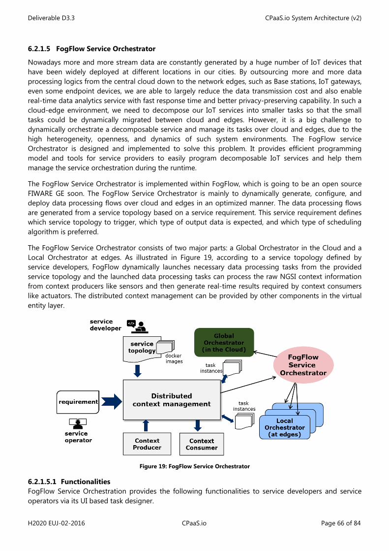
Deliverable D3.3 CPaaS.io System Architecture (v2)
H2020 EUJ-02-2016 CPaaS.io Page 66 of 84
6.2.1.5 FogFlow Service Orchestrator
Nowadays more and more stream data are constantly generated by a huge number of IoT devices that have been widely deployed at different locations in our cities. By outsourcing more and more data processing logics from the central cloud down to the network edges, such as Base stations, IoT gateways, even some endpoint devices, we are able to largely reduce the data transmission cost and also enable real-time data analytics service with fast response time and better privacy-preserving capability. In such a cloud-edge environment, we need to decompose our IoT services into smaller tasks so that the small tasks could be dynamically migrated between cloud and edges. However, it is a big challenge to dynamically orchestrate a decomposable service and manage its tasks over cloud and edges, due to the high heterogeneity, openness, and dynamics of such system environments. The FogFlow service Orchestrator is designed and implemented to solve this problem. It provides efficient programming model and tools for service providers to easily program decomposable IoT services and help them manage the service orchestration during the runtime.
The FogFlow Service Orchestrator is implemented within FogFlow, which is going to be an open source FIWARE GE soon. The FogFlow Service Orchestrator is mainly to dynamically generate, configure, and deploy data processing flows over cloud and edges in an optimized manner. The data processing flows are generated from a service topology based on a service requirement. This service requirement defines which service topology to trigger, which type of output data is expected, and which type of scheduling algorithm is preferred.
The FogFlow Service Orchestrator consists of two major parts: a Global Orchestrator in the Cloud and a Local Orchestrator at edges. As illustrated in Figure 19, according to a service topology defined by service developers, FogFlow dynamically launches necessary data processing tasks from the provided service topology and the launched data processing tasks can process the raw NGSI context information from context producers like sensors and then generate real-time results required by context consumers like actuators. The distributed context management can be provided by other components in the virtual entity layer.
Figure 19: FogFlow Service Orchestrator
6.2.1.5.1 Functionalities FogFlow Service Orchestration provides the following functionalities to service developers and service operators via its UI based task designer.
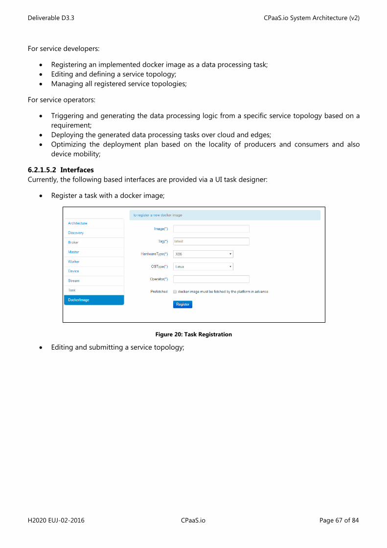
Deliverable D3.3 CPaaS.io System Architecture (v2)
H2020 EUJ-02-2016 CPaaS.io Page 67 of 84
For service developers:
• Registering an implemented docker image as a data processing task; • Editing and defining a service topology; • Managing all registered service topologies;
For service operators:
• Triggering and generating the data processing logic from a specific service topology based on a requirement;
• Deploying the generated data processing tasks over cloud and edges; • Optimizing the deployment plan based on the locality of producers and consumers and also
device mobility;
6.2.1.5.2 Interfaces Currently, the following based interfaces are provided via a UI task designer:
• Register a task with a docker image;
Figure 20: Task Registration
• Editing and submitting a service topology;
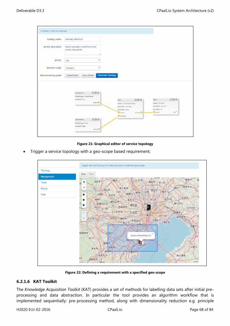
Deliverable D3.3 CPaaS.io System Architecture (v2)
H2020 EUJ-02-2016 CPaaS.io Page 68 of 84
Figure 21: Graphical editor of service topology
• Trigger a service topology with a geo-scope based requirement;
Figure 22: Defining a requirement with a specified geo-scope
6.2.1.6 KAT Toolkit
The Knowledge Acquisition Toolkit (KAT) provides a set of methods for labelling data sets after initial pre-processing and data abstraction. In particular the tool provides an algorithm workflow that is implemented sequentially: pre-processing method, along with dimensionality reduction e.g. principle
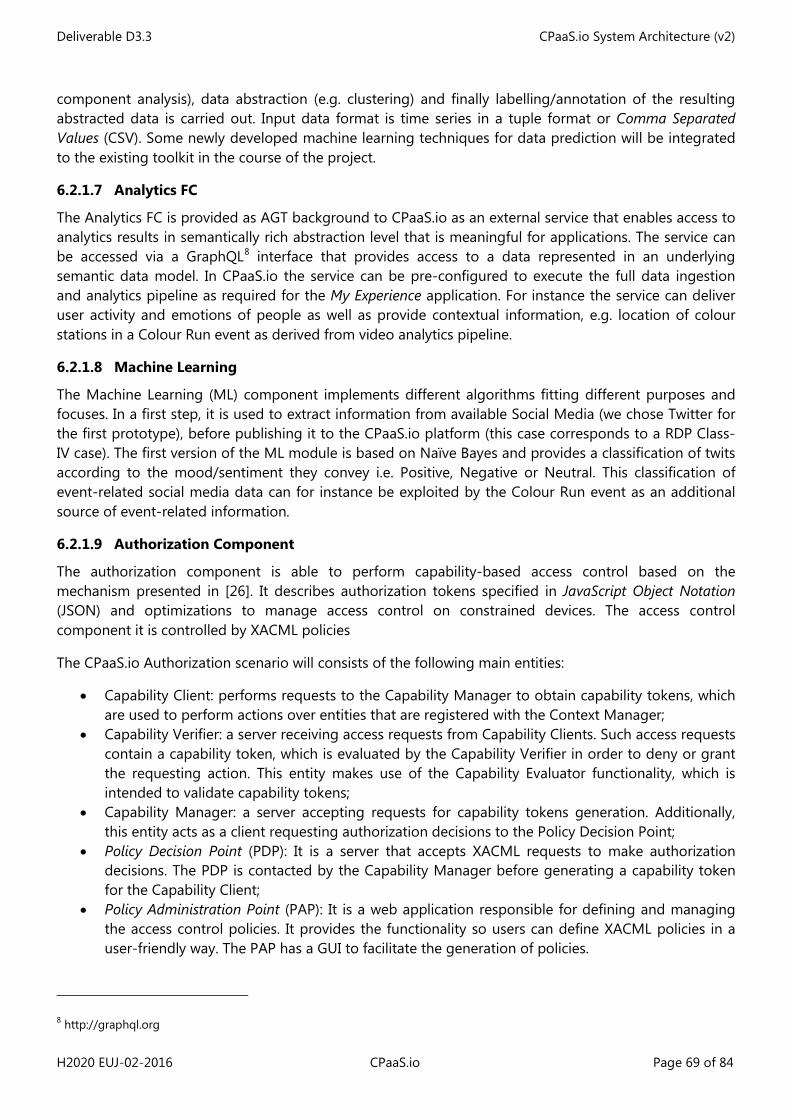
Deliverable D3.3 CPaaS.io System Architecture (v2)
H2020 EUJ-02-2016 CPaaS.io Page 69 of 84
component analysis), data abstraction (e.g. clustering) and finally labelling/annotation of the resulting abstracted data is carried out. Input data format is time series in a tuple format or Comma Separated Values (CSV). Some newly developed machine learning techniques for data prediction will be integrated to the existing toolkit in the course of the project.
6.2.1.7 Analytics FC
The Analytics FC is provided as AGT background to CPaaS.io as an external service that enables access to analytics results in semantically rich abstraction level that is meaningful for applications. The service can be accessed via a GraphQL8 interface that provides access to a data represented in an underlying semantic data model. In CPaaS.io the service can be pre-configured to execute the full data ingestion and analytics pipeline as required for the My Experience application. For instance the service can deliver user activity and emotions of people as well as provide contextual information, e.g. location of colour stations in a Colour Run event as derived from video analytics pipeline.
6.2.1.8 Machine Learning
The Machine Learning (ML) component implements different algorithms fitting different purposes and focuses. In a first step, it is used to extract information from available Social Media (we chose Twitter for the first prototype), before publishing it to the CPaaS.io platform (this case corresponds to a RDP Class-IV case). The first version of the ML module is based on Naïve Bayes and provides a classification of twits according to the mood/sentiment they convey i.e. Positive, Negative or Neutral. This classification of event-related social media data can for instance be exploited by the Colour Run event as an additional source of event-related information.
6.2.1.9 Authorization Component
The authorization component is able to perform capability-based access control based on the mechanism presented in [26]. It describes authorization tokens specified in JavaScript Object Notation (JSON) and optimizations to manage access control on constrained devices. The access control component it is controlled by XACML policies
The CPaaS.io Authorization scenario will consists of the following main entities:
• Capability Client: performs requests to the Capability Manager to obtain capability tokens, which are used to perform actions over entities that are registered with the Context Manager;
• Capability Verifier: a server receiving access requests from Capability Clients. Such access requests contain a capability token, which is evaluated by the Capability Verifier in order to deny or grant the requesting action. This entity makes use of the Capability Evaluator functionality, which is intended to validate capability tokens;
• Capability Manager: a server accepting requests for capability tokens generation. Additionally, this entity acts as a client requesting authorization decisions to the Policy Decision Point;
• Policy Decision Point (PDP): It is a server that accepts XACML requests to make authorization decisions. The PDP is contacted by the Capability Manager before generating a capability token for the Capability Client;
• Policy Administration Point (PAP): It is a web application responsible for defining and managing the access control policies. It provides the functionality so users can define XACML policies in a user-friendly way. The PAP has a GUI to facilitate the generation of policies.
8 http://graphql.org
Deliverable D3.3 CPaaS.io System Architecture (v2)
H2020 EUJ-02-2016 CPaaS.io Page 70 of 84
6.2.1.9.1 Functionalities This component, as described will be responsible for making authorization decisions. In this sense, this component will have the following functionalities:
• Policy generation: In order to provide new access control rules, thanks to the PAP, administrators will be able to add new access control policies;
• Policy validation: Every receiving access request must be validated by the PDP; • CT generation: If the access to a specific resource is granted, the authorization component
provides a Capability Token in which such authorization is granted; • Secure group communications: In this sense, the authorization component can encrypt the
information to be provided to a group of consumers allowing only the ones with the right credentials to decrypt that information.
6.2.1.9.2 Interfaces • According to the specific functionalities defined in the last section, each of this functionality will
have the corresponding interface in order to grant authorization access to the resources to the appropriate consumers. In this sense, the following interfaces or end points should be provided by our authorization component:Policy generation: A certificate must be provided in order to validate the profile and permissions of the user requesting such generation. In addition, the triplet (resource/s, subject/s, action/s) must be provided too;
• Policy validation: This interface should receive the request in a JSON format, the identity of the user and an authentication token which make possible to generate an access control decision. If the access is granted, a CT will be provided to the requester;
• Secure group communications: The authorization component must have an interface which allow requesters to provide the kind of policy (attribute-based encryption) must be applied.
6.2.1.10 Identity Management
The IdM module is responsible for managing the identities of the smart objects and users. The module is able to take into account privacy concerns to manage subjects’ credentials (from users or smart objects), in a privacy-preserving way relying on anonymous credential systems. It is able to endow subjects with mechanisms to ensure anonymity, which is done mainly issuing pseudonyms and proof of credentials to minimal personal data disclosure.
The Identity Management system is responsible for managing and storing the credentials, which are used by subjects to request information from an IoT services. The IdM allows users to obtain the proper credentials that can be use afterwards to derive proofs of identity to be presented to a Verifier (e.g., IoT Service provider) in order to prove the identity condition while disclosing the minimum amount of private information.
The component is endowed with the Idemix cryptographic engine that is responsible for low level cryptographic operations required by the anonymous credential system. The information provided by the Context Manager module is used by the IdM to handle the usage of partial identities under a specific context.
The CPaaS.io IdM has been integrated within the FIWARE IdM, i.e., the Keyrock IdM. The CPaaS.io IdM Issuer, which is in charge of generating the Idemix credentials, is able to communicate with the Keyrock to generate the credentials based on the attributes stored in the Keyrock for the user requesting the credential. To this end, the CPaaS.io IdM provides a Java library to interact with Keyrock by means of the SCIM standard [29]. This library provides methods such as add, remove or update users.
Deliverable D3.3 CPaaS.io System Architecture (v2)
H2020 EUJ-02-2016 CPaaS.io Page 71 of 84
Because CPaaS.io IdM relies on Keyrock, users profile management is delegated to Keyrock, the rest of the components of the CPaaS.io framework interacts with Keyrock through the CPaaS.io IdM.
The IdM components that have been designed and implemented in the scope of CPaaS.io are enumerated below:
• CPaaS.io IdM Client: This is a client application that allows obtaining Idemix credentials from the Issuer Server. It also allows interacting with the Verifier server which can validate the partial identity derived from the credential;
• CPaaS.io-Issuer-Server: This is a web application which allows generating Idemix credentials for clients. The client must be authenticated against the Issuer using a valid certificate. The Issuer also supports the verification functionality;
• CPaaS.io-Verifier-Server: This is a web application, which is able to validate partial identities presented by the client application;
• CPaaS.io-IdM-Enabled-Capability Manager: This is a web application that allows users to obtain capability tokens using their partial identities. In other words, it allows authenticating and demonstrating their attributes by means of Idemix proofs of having a valid credential issued by the Issuer;
• CPaaS.io IdM KeyRock Client: This is a library that provides a basic API for identity management by implementing a client to interact with the FI-WARE KeyRock server.
6.2.1.10.1 Functionalities The main functionalities provided by this component are related to registering and authentication operations. The first one, which should be done by the administrator providing for this purpose his credentials, and the second one which must be opened to all the users to allow them to log into the platforms.
6.2.1.10.2 Interfaces In light to the previous functionalities two interfaces will be provided:
• Registering new users: The interface provided by the IdM will need the credentials of the administrator, his username and password, and a parameter indicating the new user and their corresponding attributes;
• Authentication: This interface will receive the username and password of the users in order to be validated.
6.2.1.11 Authentication
The authentication module verifies if a subject is truly who or what it claims to be. Authentication services are provided by the CPaaS.io IdM system. Besides the conventional password-based and key-based mechanisms, the CPaaS.io IdM also supports authentication based on anonymous credentials.
• Login password-based authentication: The CPaaS.io IdM relies on the Keyrock IdM to perform this kind of authentication. To this end, the CPaaS.io IdM library provides a method that given the username and password authenticates the user against the keyrock and generates an authentication token that can be used afterwards to perform other actions against the Keyrock IdM. The CPaaS.io Keyrock IdM client library provides two main methods for dealing with this kind of authentication. The first method is for authenticating a user registered in the Keyrock given the password and username and its domain. The second method, provided by the Keyrock IdM client, is for validating a given token ID;
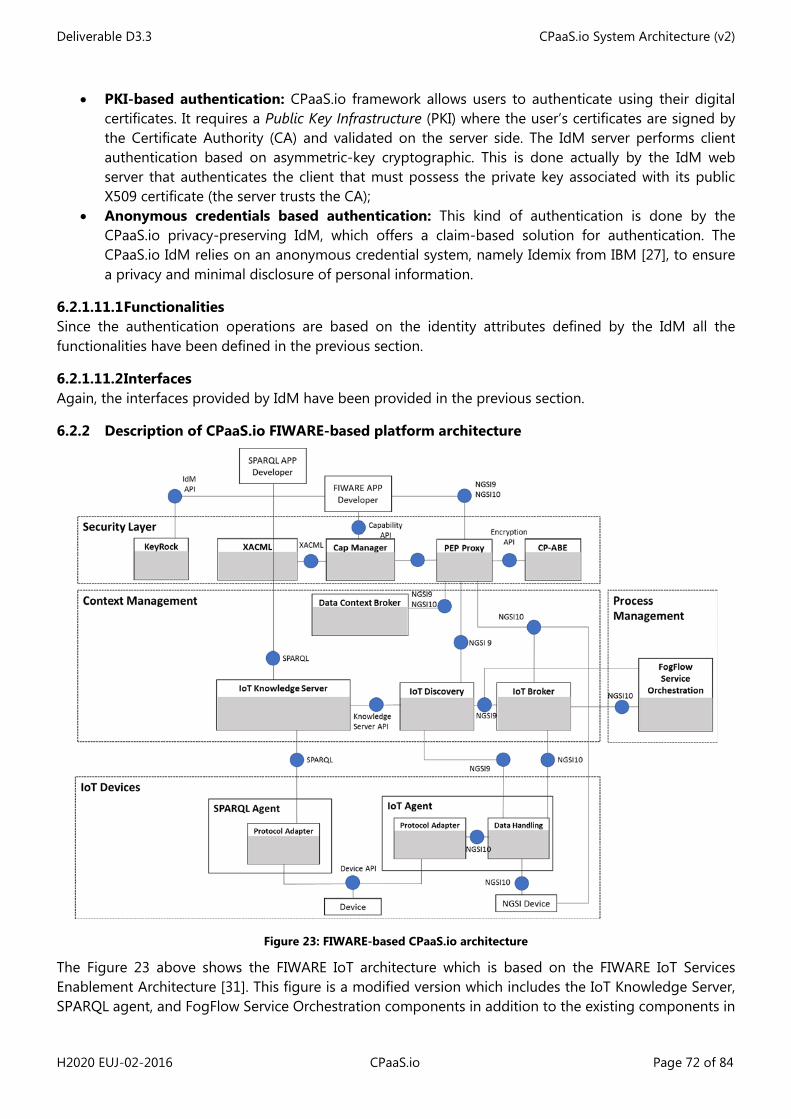
Deliverable D3.3 CPaaS.io System Architecture (v2)
H2020 EUJ-02-2016 CPaaS.io Page 72 of 84
• PKI-based authentication: CPaaS.io framework allows users to authenticate using their digital certificates. It requires a Public Key Infrastructure (PKI) where the user’s certificates are signed by the Certificate Authority (CA) and validated on the server side. The IdM server performs client authentication based on asymmetric-key cryptographic. This is done actually by the IdM web server that authenticates the client that must possess the private key associated with its public X509 certificate (the server trusts the CA);
• Anonymous credentials based authentication: This kind of authentication is done by the CPaaS.io privacy-preserving IdM, which offers a claim-based solution for authentication. The CPaaS.io IdM relies on an anonymous credential system, namely Idemix from IBM [27], to ensure a privacy and minimal disclosure of personal information.
6.2.1.11.1 Functionalities Since the authentication operations are based on the identity attributes defined by the IdM all the functionalities have been defined in the previous section.
6.2.1.11.2 Interfaces Again, the interfaces provided by IdM have been provided in the previous section.
6.2.2 Description of CPaaS.io FIWARE-based platform architecture
Figure 23: FIWARE-based CPaaS.io architecture
The Figure 23 above shows the FIWARE IoT architecture which is based on the FIWARE IoT Services Enablement Architecture [31]. This figure is a modified version which includes the IoT Knowledge Server, SPARQL agent, and FogFlow Service Orchestration components in addition to the existing components in
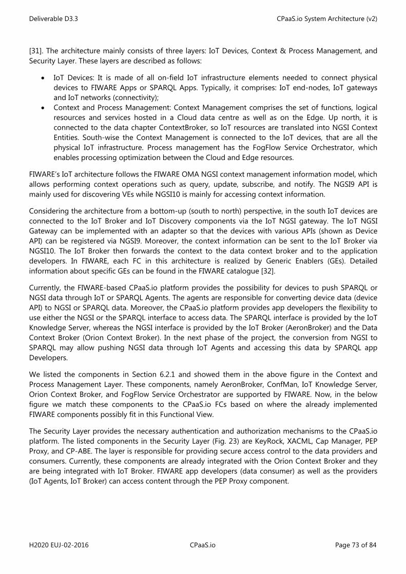
Deliverable D3.3 CPaaS.io System Architecture (v2)
H2020 EUJ-02-2016 CPaaS.io Page 73 of 84
[31]. The architecture mainly consists of three layers: IoT Devices, Context & Process Management, and Security Layer. These layers are described as follows:
• IoT Devices: It is made of all on-field IoT infrastructure elements needed to connect physical devices to FIWARE Apps or SPARQL Apps. Typically, it comprises: IoT end-nodes, IoT gateways and IoT networks (connectivity);
• Context and Process Management: Context Management comprises the set of functions, logical resources and services hosted in a Cloud data centre as well as on the Edge. Up north, it is connected to the data chapter ContextBroker, so IoT resources are translated into NGSI Context Entities. South-wise the Context Management is connected to the IoT devices, that are all the physical IoT infrastructure. Process management has the FogFlow Service Orchestrator, which enables processing optimization between the Cloud and Edge resources.
FIWARE’s IoT architecture follows the FIWARE OMA NGSI context management information model, which allows performing context operations such as query, update, subscribe, and notify. The NGSI9 API is mainly used for discovering VEs while NGSI10 is mainly for accessing context information.
Considering the architecture from a bottom-up (south to north) perspective, in the south IoT devices are connected to the IoT Broker and IoT Discovery components via the IoT NGSI gateway. The IoT NGSI Gateway can be implemented with an adapter so that the devices with various APIs (shown as Device API) can be registered via NGSI9. Moreover, the context information can be sent to the IoT Broker via NGSI10. The IoT Broker then forwards the context to the data context broker and to the application developers. In FIWARE, each FC in this architecture is realized by Generic Enablers (GEs). Detailed information about specific GEs can be found in the FIWARE catalogue [32].
Currently, the FIWARE-based CPaaS.io platform provides the possibility for devices to push SPARQL or NGSI data through IoT or SPARQL Agents. The agents are responsible for converting device data (device API) to NGSI or SPARQL data. Moreover, the CPaaS.io platform provides app developers the flexibility to use either the NGSI or the SPARQL interface to access data. The SPARQL interface is provided by the IoT Knowledge Server, whereas the NGSI interface is provided by the IoT Broker (AeronBroker) and the Data Context Broker (Orion Context Broker). In the next phase of the project, the conversion from NGSI to SPARQL may allow pushing NGSI data through IoT Agents and accessing this data by SPARQL app Developers.
We listed the components in Section 6.2.1 and showed them in the above figure in the Context and Process Management Layer. These components, namely AeronBroker, ConfMan, IoT Knowledge Server, Orion Context Broker, and FogFlow Service Orchestrator are supported by FIWARE. Now, in the below figure we match these components to the CPaaS.io FCs based on where the already implemented FIWARE components possibly fit in this Functional View.
The Security Layer provides the necessary authentication and authorization mechanisms to the CPaaS.io platform. The listed components in the Security Layer (Fig. 23) are KeyRock, XACML, Cap Manager, PEP Proxy, and CP-ABE. The layer is responsible for providing secure access control to the data providers and consumers. Currently, these components are already integrated with the Orion Context Broker and they are being integrated with IoT Broker. FIWARE app developers (data consumer) as well as the providers (IoT Agents, IoT Broker) can access content through the PEP Proxy component.
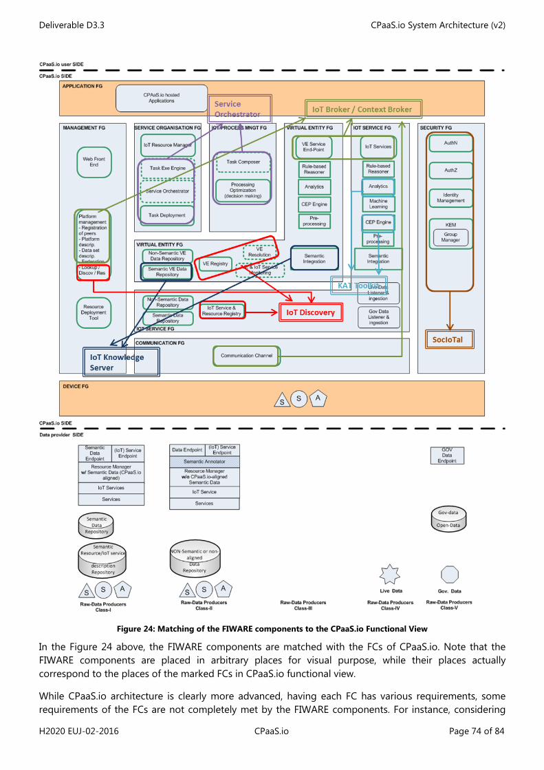
Deliverable D3.3 CPaaS.io System Architecture (v2)
H2020 EUJ-02-2016 CPaaS.io Page 74 of 84
Figure 24: Matching of the FIWARE components to the CPaaS.io Functional View
In the Figure 24 above, the FIWARE components are matched with the FCs of CPaaS.io. Note that the FIWARE components are placed in arbitrary places for visual purpose, while their places actually correspond to the places of the marked FCs in CPaaS.io functional view.
While CPaaS.io architecture is clearly more advanced, having each FC has various requirements, some requirements of the FCs are not completely met by the FIWARE components. For instance, considering
Deliverable D3.3 CPaaS.io System Architecture (v2)
H2020 EUJ-02-2016 CPaaS.io Page 75 of 84
the requirements that are listed for use-cases, Semantic VE Data Repository may require more advanced and novel features compared to the existing functionalities of the IoT Knowledge Server component. For this reason, some FIWARE components may be either extended or improved or new components should be developed during the CPaaS.io project when necessary. At this stage, the decisions have not been finalized for the implementation necessities of the proposed CPaaS.io architecture. On the other hand, some components can already meet the listed requirements of some of the FCs without further implementation effort. For instance, VE Resolution is provided by IoT Discovery and therefore IoT discovery component could be integrated without much effort.
We provide an instantiation view for the FIWARE components below. The Figure 25 below includes IoT Broker instances, IoT Knowledge Server, Context Broker, as well as IoT Discovery GEs including also their interactions (APIs).
Figure 25: Interactions of the FIWARE FCs
In the above Figure 25, the historical data is stored in CouchDB by IoT Broker. IoT Broker also forwards the context to the context broker or applications. Moreover, subscriptions are stored in and accessed from a shared SQL database by the distributed IoT Broker instances. Registrations are saved in the Registration Respository (ConfMan) via NGSI9. Lastly, IoT Agent is responsible for providing context of VEs in NGSI9/10 information model and therefore it can be considered as an NGSI device.
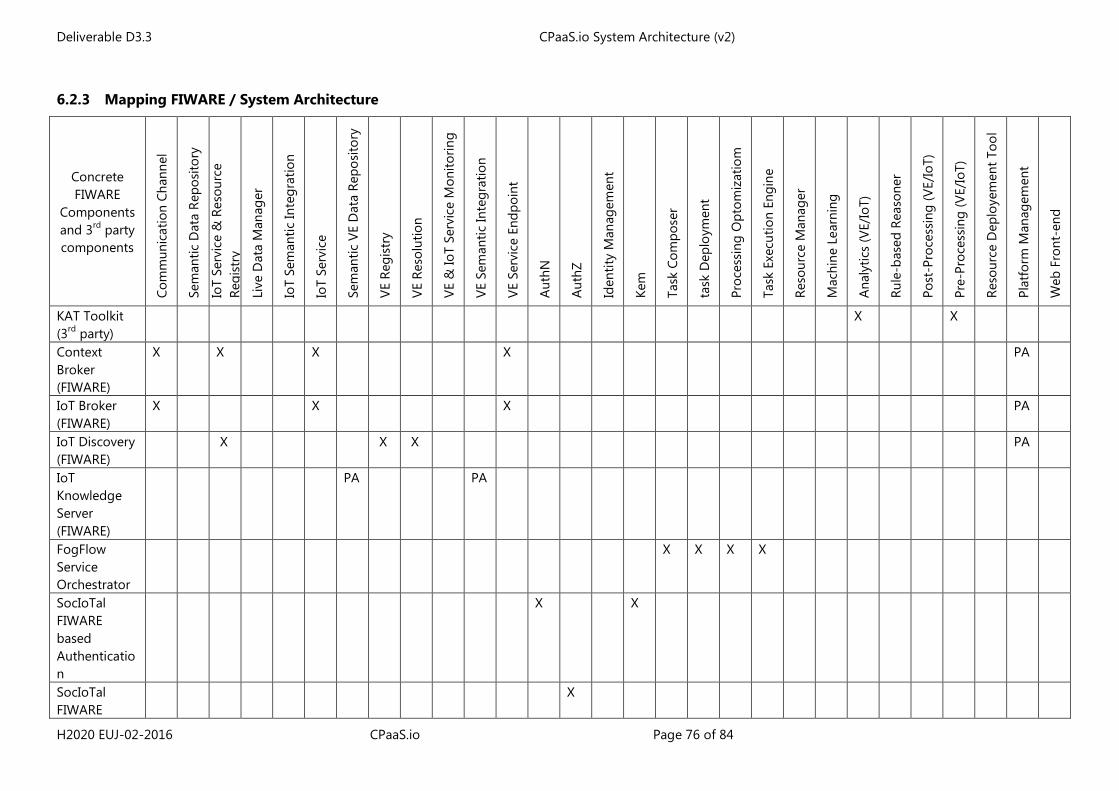
Deliverable D3.3 CPaaS.io System Architecture (v2)
H2020 EUJ-02-2016 CPaaS.io Page 76 of 84
6.2.3 Mapping FIWARE / System Architecture
Concrete FIWARE
Components and 3rd party components
Com
mun
icat
ion
Chan
nel
Sem
antic
Dat
a Re
posi
tory
IoT
Serv
ice
& R
esou
rce
Regi
stry
Live
Dat
a M
anag
er
IoT
Sem
antic
Inte
grat
ion
IoT
Serv
ice
Sem
antic
VE
Dat
a Re
posi
tory
VE R
egis
try
VE R
esol
utio
n
VE &
IoT
Serv
ice
Mon
itorin
g
VE S
eman
tic In
tegr
atio
n
VE S
ervi
ce E
ndpo
int
Aut
hN
Aut
hZ
Iden
tity
Man
agem
ent
Kem
Task
Com
pose
r
task
Dep
loym
ent
Proc
essi
ng O
ptom
izat
iom
Task
Exe
cutio
n En
gine
Reso
urce
Man
ager
Mac
hine
Lea
rnin
g
Ana
lytic
s (V
E/Io
T)
Rule
-bas
ed R
easo
ner
Post
-Pro
cess
ing
(VE/
IoT)
Pre-
Proc
essi
ng (V
E/Io
T)
Reso
urce
Dep
loye
men
t Too
l
Plat
form
Man
agem
ent
Web
Fro
nt-e
nd
KAT Toolkit (3rd party)
X X
Context Broker (FIWARE)
X X X X PA
IoT Broker (FIWARE)
X X X PA
IoT Discovery (FIWARE)
X X X PA
IoT Knowledge Server (FIWARE)
PA PA
FogFlow Service Orchestrator
X X X X
SocIoTal FIWARE based Authentication
X X
SocIoTal FIWARE
X
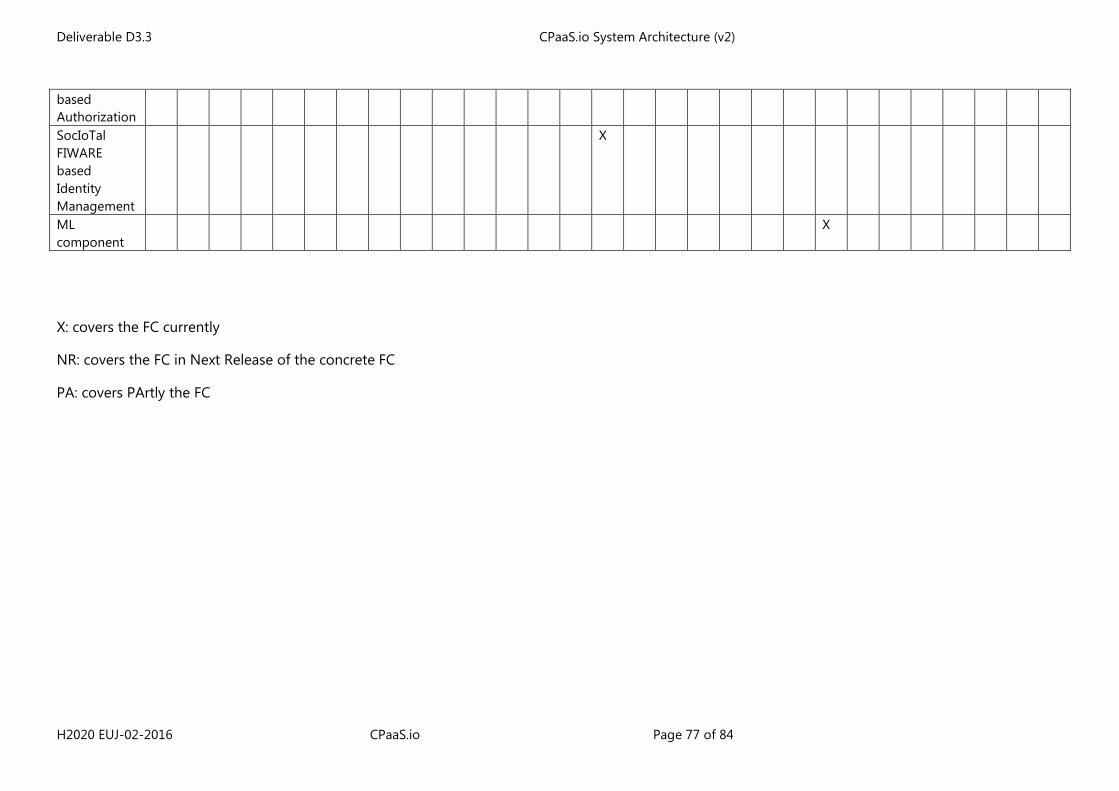
Deliverable D3.3 CPaaS.io System Architecture (v2)
H2020 EUJ-02-2016 CPaaS.io Page 77 of 84
based Authorization SocIoTal FIWARE based Identity Management
X
ML component
X
X: covers the FC currently
NR: covers the FC in Next Release of the concrete FC
PA: covers PArtly the FC
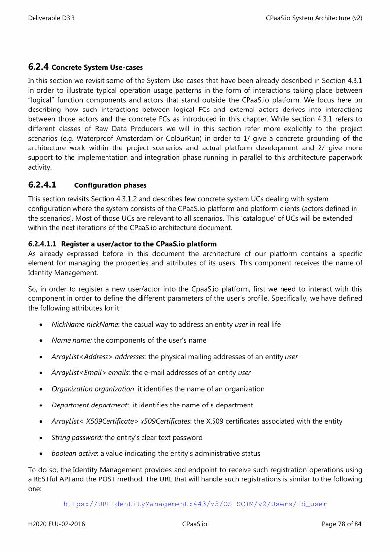
Deliverable D3.3 CPaaS.io System Architecture (v2)
H2020 EUJ-02-2016 CPaaS.io Page 78 of 84
6.2.4 Concrete System Use-cases In this section we revisit some of the System Use-cases that have been already described in Section 4.3.1 in order to illustrate typical operation usage patterns in the form of interactions taking place between “logical” function components and actors that stand outside the CPaaS.io platform. We focus here on describing how such interactions between logical FCs and external actors derives into interactions between those actors and the concrete FCs as introduced in this chapter. While section 4.3.1 refers to different classes of Raw Data Producers we will in this section refer more explicitly to the project scenarios (e.g. Waterproof Amsterdam or ColourRun) in order to 1/ give a concrete grounding of the architecture work within the project scenarios and actual platform development and 2/ give more support to the implementation and integration phase running in parallel to this architecture paperwork activity.
6.2.4.1 Configuration phases This section revisits Section 4.3.1.2 and describes few concrete system UCs dealing with system configuration where the system consists of the CPaaS.io platform and platform clients (actors defined in the scenarios). Most of those UCs are relevant to all scenarios. This ‘catalogue’ of UCs will be extended within the next iterations of the CPaaS.io architecture document.
6.2.4.1.1 Register a user/actor to the CPaaS.io platform As already expressed before in this document the architecture of our platform contains a specific element for managing the properties and attributes of its users. This component receives the name of Identity Management.
So, in order to register a new user/actor into the CpaaS.io platform, first we need to interact with this component in order to define the different parameters of the user’s profile. Specifically, we have defined the following attributes for it:
• NickName nickName: the casual way to address an entity user in real life
• Name name: the components of the user’s name
• ArrayList<Address> addresses: the physical mailing addresses of an entity user
• ArrayList<Email> emails: the e-mail addresses of an entity user
• Organization organization: it identifies the name of an organization
• Department department: it identifies the name of a department
• ArrayList< X509Certificate> x509Certificates: the X.509 certificates associated with the entity
• String password: the entity's clear text password
• boolean active: a value indicating the entity's administrative status
To do so, the Identity Management provides and endpoint to receive such registration operations using a RESTful API and the POST method. The URL that will handle such registrations is similar to the following one:
https://URLIdentityManagement:443/v3/OS-SCIM/v2/Users/id_user
Deliverable D3.3 CPaaS.io System Architecture (v2)
H2020 EUJ-02-2016 CPaaS.io Page 79 of 84
The body of this request should contain a JSON text that must meet the specification of SCIM core (RFC 7643 SCIM Core Schema). Since this operation must be done by the administrators of the platform, such operation requires also the addition of a certificate in order to securely validates the origin of such request.
6.2.4.1.2 Create and assign security credential Although after applying the previous operation the user has been registered in the CPaaS.IO platform, he does not have any access rights over the information stored in it. So, we need to establish the security policies for such information. This is done thanks to the XACML component which comprises the following entities: Policy Administration Point (PAP), Policy Decision Point (PDP) and Policy Enforcement Point (PEP).
Thanks to an administration web page, the administrator can establish the different security policies that will be applied to the user and the resources stored in the platform.
Figure 26. PAP Web configuration interface
After having logged in, the administrator will be able to generate new XACML policies. These are identified by a triplet (resource, subject, action) which means that for a specific resource or resources, the selected subjects or users will be able to perform the specified actions over them. Applied to our platform, the resources will be the different stored entities with their corresponding attributes, the subjects are the different users of the platform, and finally, the actions could be register, updating or requesting the information.
Thanks to the definition of these policies, the Capability Manager, after receiving an authorization request will forward it to the PDP which will carry out the validation operation over it. If the validation
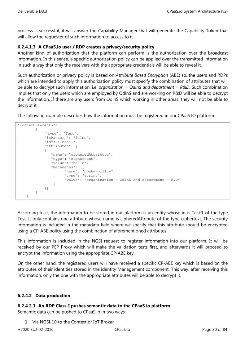
Deliverable D3.3 CPaaS.io System Architecture (v2)
H2020 EUJ-02-2016 CPaaS.io Page 80 of 84
process is successful, it will answer the Capability Manager that will generate the Capability Token that will allow the requester of such information to access to it.
6.2.4.1.3 A CPaaS.io user / RDP creates a privacy/security policy Another kind of authorization that the platform can perform is the authorization over the broadcast information. In this sense, a specific authorization policy can be applied over the transmitted information in such a way that only the receivers with the appropriate credentials will be able to reveal it.
Such authorization or privacy policy is based on Attribute Based Encryption (ABE) so, the users and RDPs which are intended to apply this authorization policy must specify the combination of attributes that will be able to decrypt such information, i.e. organization = OdinS and department = R&D. Such combination implies that only the users which are employed by OdinS and are working on R&D will be able to decrypt the information. If there are any users from OdinS which working in other areas, they will not be able to decrypt it.
The following example describes how the information must be registered in our CPaaS.IO platform.
"contextElements": [ {
"type": "Test", "isPattern": "false", "id": "Test:1", "attributes": [ { "name": "cipheredAttribute", "type": "ciphertext", "value": "hello", "metadatas": [{ "name": "cpabe-policy", "type": "string", "value": "organization = OdinS and department = R&D" }] }] } ]
According to it, the information to be stored in our platform is an entity whose id is Test:1 of the type Test. It only contains one attribute whose name is cipheredAttribute of the type ciphertext. The security information is included in the metadata field where we specify that this attribute should be encrypted using a CP-ABE policy using the combination of aforementioned attributes.
This information is included in the NGSI request to register information into our platform. It will be received by our PEP_Proxy which will make the validation tests first, and afterwards it will proceed to encrypt the information using the appropriate CP-ABE key.
On the other hand, the registered users will have received a specific CP-ABE key which is based on the attributes of their identities stored in the Identity Management component. This way, after receiving this information, only the one with the appropriate attributes will be able to decrypt it.
6.2.4.2 Data production
6.2.4.2.1 An RDP Class-I pushes semantic data to the CPaaS.io platform Semantic data can be pushed to CPaaS.io in two ways:
1. Via NGSI-10 to the Context or IoT Broker
Deliverable D3.3 CPaaS.io System Architecture (v2)
H2020 EUJ-02-2016 CPaaS.io Page 81 of 84
2. Via SPARQL to the Semantic Data Repository
When using the NGSI-10 interface the RDP must follow certain conventions in order to enable semantic interoperability. For instance entity types must link to RDFS classes (rdfs:class or owl:class) and entity id must use the same identifiers as RDF instances. Similar conventions apply for attribute types and names. Details will be described in the upcoming deliverable D6.3 [8].
Alternatively the data can directly pushed to the Semantic Data repository using SPARQL INSERT or UPDATE requests.
Deliverable D3.3 CPaaS.io System Architecture (v2)
H2020 EUJ-02-2016 CPaaS.io Page 82 of 84
7 Conclusions & Next Steps
We have provided in this second version, a first consolidation of the CPaaS.io logical architecture (architectural Views and Perspectives with requirement tracking) and an update of the two instantiation views that shows how this logical architecture is being instantiated using two different technologies, namely u2 for the Japanese side and FIWARE for the European counterpart.
This second version of the CPaaS.io architecture focuses on the main aspects of the CPaaS.io architecture and does not fully cover yet some aspects like task distribution, federation and FIWARE-based / u2-based interoperability, which are topics still under discussion.
The next version of the CPaaS.io architecture (D3.5) will be updated in M24 and will provide the following additions and improvements:
• Updated Functional View: refinement of the logical architecture (updated list of FCs) with special focus on Edge Computing and Semantic Integration;
• Updated Information View: o Updated list of system UCs covering more scenarios and more FCs; o Overall description of the CPaaS.io ontology
• Updated Instantiation views (u2- and FIWARE- based concrete architectures) with more detailed information about the interfaces and concrete system UCs;
• Solutions for inter-platform interoperability; • Solution for platform federation; • Updated Volere template (update of requirement mapping); • Updated system Perspectives.
Deliverable D3.3 CPaaS.io System Architecture (v2)
H2020 EUJ-02-2016 CPaaS.io Page 83 of 84
8 References
[1] F. Carrez et al., “IoT-A Deliverable D1.5 – Final Architectural Reference Model for the IoT v3.0”, www.iot-a.eu/public/public-documents/
[2] D2.1: CPaaS.io deliverable “Requirement Specification (V1)”, Martin Strohbach ed.
[3] D2.2: CPaaS.io deliverable: “Prototype, 1st release”, Martin Strohbach ed.
[4] D3.1: CPaaS.io deliverable “Requirement Collection and Analysis”, François Carrez ed.
[5] D5.1: CPaaS.io deliverable “ Empowerment Components Definition”, Antonio Skármeta, Juan A. Martínez ed.
[6] D5.2: CPaaS.io deliverable “User Empowerment Architectural”, Antonio Skármeta, Juan A. Martínez ed.
[7] D6.1: CPaaS.io deliverable “Holistic Data Management State of the Art”, Mariane Fraefel ed.
[8] D6.3: CPaaS.io deliverable “Holistic Data Management: Initial Concepts and Models”, Adrian Gschwend ed.
[9] ETSI TR 103 167Machine-to-Machine Communications (M2M); Threat analysis and counter-measures to M2M service layer
[10] Haller, S et al: “A Domain Model for the Internet of Things”, in iTHINGS’2013 proceedings, Beijing, China (see also IEEE eXplore)
[11] Ho, E. & al., “IoT-A Deliverable D6.1 – Requirements list”, www.iot-a.eu/public/public-documents/
[12] IoT Semantic Interoperability: Research Challenges, Best Practices, Recommendations and Next Steps [IERC – European Research Cluster on the IoT], Position Paper available at www.internet-of-things-research.eu/pdf/IERC_Position_Paper_IoT_Semantic_Interoperability_Final.pdf
[13] IoT-A web site: http://www.iot-a.eu
[14] oneM2M white paper, January 2015, http://www.onem2m.org/images/files/oneM2M-whitepaper-January-2015.pdf
[15] oneM2M Functional Architecture, http://www.onem2m.org/images/files/deliverables/TS-0001-Functional_Architecture-V1_6_1.pdf
[16] OneM2M security solutions”, oneM2M-TR-0008-Security-V1.0.0, 2014
[17] Pastor, A. “Updated Requirements List”, www.iot-a.eu/public/public-documents/
[18] OneM2M security solutions”, oneM2M-TR-0008-Security-V1.0.0, 2014
[19] “Requirements Specification for Urban Plarforms v2.2” prepared by Demand-Side Engagement Stream I the context of the European Innovation Partnership for Smart Cities & Communities (EIP_SCC) Integrated Infrasturcture Action Cluster – Urban Platform
[20] N. Rozanski and E. Woods, “Applying Viewpoints and Views to Software Architecture” , Addison Wesley, 2011
[21] SMARTIE Project Deliverable D2.2 “Requirements”
[22] SPARQL Protocol And RDF Query Language http://www.w3.org/TR/rdf-sparql-query/
[23] UNIs: List of IoT-A UNIfied requierementS. Available at http://www.iot-a.eu/public/requirements
[24] Volere Requirements Resources, http://www.volere.co.uk/
Deliverable D3.3 CPaaS.io System Architecture (v2)
H2020 EUJ-02-2016 CPaaS.io Page 84 of 84
[25] E. Rissanen, extensible access control markup language (xacml) version 3.0 oasis standard (2012).
[26] J. L. Hernández-Ramos, A. J. Jara, L. Marín, and A. F. Skarmeta, “Dcapbac: Embedding authorization logic into smart things through ecc optimizations,” International Journal of Computer Mathematics, pp. 1–22, 2014.
[27] Specification of the Identity Mixer Cryptographic Library. Version 2.3.40 IBM Research, Zurich January 30, 2013. Available http://www.zurich.ibm.com/idemix/
[28] Bethencourt, J., Sahai, A., & Waters, B. (2007, May), Ciphertext-policy attribute-based encryption. In Security and Privacy, 2007. SP'07. IEEE Symposium on (pp. 321-334).
[29] System for Cross-domain Identity Management. (SCIM). Internet Engineering Task Force (IETF), RFC 7643. ISSN: 2070-1721.
[30] www.viewpoints-and-perspectives.info/home/perspectives/ Last accessed 26/01/2017
[31] FIWARE Internet of Things (IoT) services enablement architecture. Available https://forge.fiware.org/plugins/mediawiki/wiki/fiware/index.php/Internet_of_Things_(IoT)_Services_Enablement_Architecture
[32] FIWARE Catalogue, Available https://catalogue.fiware.org/enablers
[33] FIWARE architecture description, : IoT Broker. Available https://forge.fiware.org/plugins/mediawiki/wiki/fiware/index.php/FIWARE.ArchitectureDescription.IoT.Backend.IoTBroker
[34] FIWARE architecture description, : IoT Discovery. Available https://forge.fiware.org/plugins/mediawiki/wiki/fiware/index.php/FIWARE.ArchitectureDescription.IoT.Backend.IoTDiscovery
[35] IoT Broker interface specification. Available http://docs.iotbrokerngsiinterface.apiary.io/#reference/0/standard-context-query
[36] FIWARE NGSI 10 Open RESTful API Specification. Available https://forge.fiware.org/plugins/mediawiki/wiki/fiware/index.php/FI-WARE_NGSI-10_Open_RESTful_API_Specification
[37] FIWARE NGSI API v.1 Walkthrough. Available https://fiware-orion.readthedocs.io/en/master/user/walkthrough_apiv1/index.html
[38] OASIS Standard. eXtensible Access Control Markup Language (XACML) Version 3.0. January 2013: http://docs.oasis-open.org/xacml/3.0
[39] Gusmeroli, S., Piccione, S., &Rotondi, D. (2013). A capability-based security approach to manage access control in the internet of things. Mathematical and Computer Modelling, 58(5), 1189-1205.