Embed Size (px)
Citation preview

Networking in Active System 800
1
Jaiwant Virk
Dell Force10 Product Management
Dell Active System 800
And Network Architecture

Networking in Active System 800
2
Table of Contents Introduction ............................................................................................................. 3
Active System Network Layout ....................................................................................... 3
Active System Manager and Dell Force10 IO Aggregator ...................................................... 5
Active System and Dell Force10 S4810 switch .................................................................. 6
Connecting Active System into a Data Center ..................................................................... 7
Physical Media Options to uplink the Active System........................................................... 7
Technology Options to uplink the Active System............................................................... 8
Creating an Active System Scale Out ............................................................................. 9
Converged iSCSI and LAN ......................................................................................... 10
Connecting Active System to Cisco Nexus 5548 core ........................................................ 11
Summary ............................................................................................................. 13
Appendix ............................................................................................................... 14
Dell S4810 Core with VLT configuration ....................................................................... 14
Cisco Nexus 5548 Core with vPC configuration ............................................................... 16

Networking in Active System 800
3
Introduction Active System 800 comes in as a latest pre-engineered virtualization platform designed for organizations seeking a converged value added infrastructure expedited deployment of applications and a rapid, low risk path to private clouds. Previously known as Active System, Active System is created for large data centers, Active Infrastructure leverages state-of-the-art, proven components — Dell PowerEdge™ Blade servers, Dell EqualLogic™ storage and Dell Force10 Networking— to deliver top notch performance and scalability. It provides the entire infrastructure — servers, storage, networking, power, cabling, rack, Dell management extensions and initial deployment services. It is available partially racked, cabled, and delivered to your site, to speed deployment. Dell Services will deploy and configure the solution tailored for business needs and ready to be integrated into the datacenter. Active System 800 is offered in configurations with either VMware® vSphere® or Microsoft® Windows Server® 2008 R2 with Hyper-V® role enabled Hypervisors.
Major benefits of Active System are accelerated time to deployment, reliable pre-engineered infrastructure and faster scalability, vertically within the rack and horizontally with more Active System racks.
This version of Active System Infrastructure includes:
• Dell12th Generation PowerEdge M620 Servers • Dell Blade IO Aggregator for 10GbE Networking • Dell Top-of-Rack switch S4810 • Dell EqualLogic iSCSI Storage • Dell Active System Manager for management • Dell partner software from VMware, Microsoft • Deployment services • Pro-Support with Next Business Day from Dell
In this paper we discuss the Dell 10GbE networking and the use cases of its deployment in a data center.
Active System Network Layout In this whitepaper we focus on how Active System rack integrates into the existing LAN network infrastructure. We discuss the interoperability of Active System first in Dell Force10 based infrastructures and later in a Cisco networking environments. We discuss some common deployment scenarios that Active System is likely to meet in a data center. The Active System rack internally has a network of its own that binds the blade chassis with storage and LAN. How this gets connected into the external world, as seen in figure 1, and how it would scale beyond a single rack will be discussed in this paper.
From a pure networking perspective the value proposition of the Active System network is four fold.
1. Compelling TCO of using Dell Networking.
2. Highly interoperable with any vendor.
3. Ease of management and deployment.
4. Scalable and reliable design that grows with the business needs.

Networking in Active System 800
4
We start with emphasizing the ease of deployment and management for the Active System. The figure 1 shows the network inside the rack. This internal network is all configured onsite or pre-configured and ready to use by the customer. The VMs are initiated with an operational SAN. This network is partially pre-packed inside a rack that needs power and external connectivity.
Inside a single Dell Active System 1000 rack there are one or two M1000e chassis with M620 blade servers per chassis and a two IO Aggregator blades, LAN & SAN converged Ethernet 10GbE Top-Of-Rack switches, upto eight EqualLogic storage arrays, a management switch and two management servers.
Figure 1. Active System Network inside the rack
A brief description of the network inside the rack is given below.
The IO Aggregator is capable of 24 front-end ports and upto 32 facing the servers. In this Active System only 16 server facing ports are active and only the 2x 40G uplink ports are in use. The external facing 40G interfaces have been converted into 4x10GbE interfaces using the break-out cable that connects to 40G on one side and breaks out into 4 LC connectors. Check figure-3 for a picture of this break-out cable. For redundancy these four LC strands connect into two different S4810 switches, two strands to each s4810 forming a LAG. The server facing ports connect to the 16 half-height M620 servers. As the Active System 800 is scalable upto two M1000e chassis, all IO Aggregator, 2 in each chassis, connect to

Networking in Active System 800
5
the same pair of S4810s. The two S4810 switches connect to each other over an aggregated link of 2 x 40GbE interfaces creating an inter-switch bandwidth of 80Gbits.
Active Systems is a solution that leverages the new DCB standard, supporting the segmentation of LAN & SAN network traffic on the same infrastructure which otherwise would use completely separate hardware. The SAN traffic is aggregates on the S4810 along with the LAN traffic, where it’s switched towards the EqualLogic iSCSI SAN consisting of upto 8 Arrays.
Active System Manager and Dell Force10 IO Aggregator
Active System Manager is infrastructure management software that is part of the Active System 800. It simplifies infrastructure configuration, collapses management tools and drives automation and consistency. Through capabilities such as template-based provisioning, automated configuration and infrastructure lifecycle management, its a single point of control for key infrastructure enabling users to minimize the number of consoles that are needed on a regular basis.
Active System Manager enables the IO Aggregator configuration in an easy way using an intuitive user interface. Below are some figures that show how the IO Aggregator, Servers, M1000e Chassis Console are all seen through the Active System Manager.
Figure 2. Active System Manager
Active System Manager addresses key factors that impact service levels, namely infrastructure configuration errors, incorrect problem troubleshooting and slow recovery from failures. Active System Manager dramatically improves accuracy of infrastructure configuration by reducing manual touch points. Setting up VLANs in IO Aggregator as shown below is intuitive and just a few clicks away compared to complexity of individual CLI based configuration.

Networking in Active System 800
6
Figure 3. VLAN configurations for IO Aggregator
Active System and Dell Force10 S4810 switch
The S4810 forms the backbone of this solution because it’s quite a versatile switch. It is a 1/10/40GbE Ethernet media and capable of being used as the top-of-rack inside the Active System as well as an aggregation or core switch for scaling out into multiple Active System in the Data Center.
Figure 4. S4810 switch
The software features combined with the hardware capabilities make this a versatile switch that can be used to consolidate 10GbE servers in the rack, build an aggregation of racks and the core. The S4810 can be a building block of a flat distributed core that is organized in a fat-tree non-blocking fabric that can scale up to tens of racks and hundreds of high-end servers. The 40GbE interfaces take the next level of 40gbE capability as the servers get to 10GbE capabilities.

Networking in Active System 800
7
Connecting Active System into a Data Center Let’s discuss how the Active Systems Infrastructure fits into a data center. We first discuss the physical media options available to connect an Active System into the Data Center Core. Next we discuss the network topology and technology options for a modern day data center.
Finally we discuss how multiple Active Systems can be aggregated at a scale that suits a medium to large data center. Dell brings forth enormous value to its data center customers by offering not just the Active Systems that roll in ready to use but also how multiple such Systems can put a large data center into operation in a very short time. This is invaluable for data centers that need to hit the ground running at a certain scale.
Physical Media Options to uplink the Active System
Connecting the Active System into the LAN is easy. Only the S4810 switches inside the rack need to be connected to the LAN core switches. The Active System rack has the front side door and a backside door. The S4810 switches can be seen on the backside side. First it would help setting up a console connection with these two switches as we may need some configurations done to get the LAN connections working.
Next identify the ports that are going to be linked to the core switches. These ports on the S4810 that need to be uplinked can be 10GbE interfaces or the 40GbE interfaces located towards right of IO facing side. The 10G interfaces would need 10G SFP+ optics if using fiber or a Twin-Ax 10G cable that doesn’t need an optic. For 40GbE you would need a 40G-to-40G twin-ax or fiber if the core is 40G capable. The cabling options can be seen below.
Figure 5. Cabling options
40G interfaces on the S4810 work in native 40GbE mode but can be converted into four 10GbE interfaces by a CLI command. If a breakout to 10GbE is needed then these are connected using a breakout cables as shown above. After the interface has been converted to operate into four 10GbE mode, the respective fiber (shown in green) or twin-ax (shown in black) are used. When using fiber, a 40GbE optical transceiver is needed. The twin-ax has a transceiver built on the cable on both the 40GbE side and the four 10GbE sides.

Networking in Active System 800
8
Technology Options to uplink the Active System
Each network is different in some respects therefore not all configurations that we discuss here maybe applicable but based on a general usability pattern seen in most networks we discuss three different topologies with which an Active System solution could be connected.
The extended Virtual Link Trunking (VLT) option The large bridge network where certain VLAN domains need to be extended beyond a few racks is still a common requirement. But only now this is achieved by what Dell’s technology that renders Spanning tree of yester years archaic, is the VLT. Virtual Link Trunking is technology where a server or bridge uplinks a Trunk into more than one switch but is unaware of that fact. The switches that make this possible run this technology by making themselves appear as a single switch for a connecting bridge or server. We call this switch pair as the VLT- pair. Both links from the bridge network can actively forward and receive traffic. The fact that both, redundancy as well as active-active full bandwidth utilization, are achieved in this technology; this is a perfect replacement for Spanning Tree based networks.
We take this technology one step further by now creating multiple tiers of VLT. Which means the VLT –Pair switches themselves uplink into another VLT-Pair formed by denser 40GbE switches. This helps us build ever larger layer-2 domains that can stretch across larger number of racks, aggregate bandwidth using the 40GbE and yet keep networks simpler. Simplicity is achieved by eliminating Spanning Tree as primary enabler of redundancy yet without creating loops.
The S4810s inside each Active System come pre-configured for VLT that facilitates multiple blade IO Aggregators to dual home into this S4180 VLT-Pair. These blade switches form a 40G LAG upwards into the VLR-Pair with 20G going to each switch in the VLT-Pair. Intra-chassis traffic, i.e server communication within the M1000e chassis would never need to leave the blade IO aggregator and inter-chassis traffic would be switched within the S4810 pair, at no point the local traffic needs to go out to core and then get switched back. Major benefits of this technology are:
1. Dual control plane on the access side that lends resiliency.
2. Full utilization of the active LAG interfaces.
3. Rack level maintenance is hitless and one switch can be kept active at all times.
Figure 6. Topology options

Networking in Active System 800
9
The routing option The second most commonly used method of connecting racks into aggregation or core layers is when routing is enabled on the top-of-rack switches. Routing entails enabling routing protocols on both sides the Active System rack as well as the core side. Commonly used IGP routing protocols like OSPF and IS-IS are well suited for this purpose. The major benefits include:
1. This option is suited for a CLOS (Distributed Core) scale out. There is no need for the S4810s in Active System to connect with each other in this option. Optionally these could form a regular LAG for an alternate path.
2. Multiple paths in routing table to the destination enable equal-cost multi-path capability. As each switch has at least two paths available, the traffic gets load balanced.
3. Limited domain of Layer-2 within the rack limits broadcast and other flooded traffic within the rack.
4. Network wide link states are visible to each Active System rack which helps in fast convergence in failures.
5. Rack level maintenance is hitless and each switch can be independently maintained.
Creating an Active System Scale Out
To build a larger core enabled for 40G, the Dell Force10 Z9000 switch would be an obvious choice in this case. Each Z9000 can support 32 line-rate 40GbE ports and could aggregate multiple racks with little or no over-subscription. When connecting multiple Active System racks, using the 40GbE uplinks from the rack, we can build a large fabric that support multi-terabit cluster. Where each Active System forms the infrastructure of a public or private cloud, the scalability to accommodate multiple tenants is achieved at the core by building a routed infrastructure in the core. The density of the Z9000 allows flattening the network tiers and creating an equal-cost fabric from any to any other point in the network.
Figure 7. Active System scale out

Networking in Active System 800
10
However, the option that can be used for large domain layer-2 requirements is the one that uses the extended VLT (eVLT) on the Z9000. The VLT-Pair thus formed can scales in terms of hundreds of servers inside the Active Systems. Using the base Active System 800 calculation, each of which has 32 servers, this Z9000 based aggregation can cover around 1000 servers inside 30 or more Active System racks.
Figure 8. Scale out on the eVLT option
Large scale networks routinely deploy Z9000 in HPC and cloud environments. Compared to a chassis (modular) switch, the density available on Z9000 gives the bet ROI in terms of switching capacity, form-factor which is 2U, and power which is fractions compared to modular chassis. Supported by FTOS operating system that has features suitable for high end switches and routers, the Z9000 becomes a great next-generation choice of a core switch.
Converged iSCSI and LAN
A major feature that enhances the Active System is the convergence of SAN and LAN over same infrastructure.
First step of convergence is the server NIC itself that uses the NPAR technology. The Network Partition technology can convert a 10GbE NIC/CNA into 4 virtual partitions. It can be used in both virtualized and non-virtualized environment. These NPARs are independent of the switches it connects to. Each partition can have its own VLAN and this VLAN maps into the physical switch.
Using this technology there are 4 partitions on each physical 10GbE NIC in the server. Of these 4 partitions 1 belongs to management traffic, one for vMotion and one for iSCSI. Thus the iSCSI traffic is segregated on the server in a separate VLAN and a DCB priority is applied to it on the physical network.
DCB is an end-to-end concept. Therefore from the server the DCB is extended to IO Aggregator, to s4810 and to the EqualLogic storage arrays. Here’s a snippet of what DCB looks like in the s4810 switch inside the Active System 800.
! interface TenGigabitEthernet 0/0 no ip address

Networking in Active System 800
11
mtu 12000 dcb-policy input pfc dcb-policy output ets ! port-channel-protocol LACP port-channel 10 mode active ! protocol lldp advertise management-tlv system-name no shutdown ! <SNIP> ! qos-policy-output OTHER ets bandwidth-percentage 95 ! qos-policy-output iSCSI ets bandwidth-percentage 5 ! dcb-input no-pfc no pfc mode on pfc priority 4 ! dcb-input pfc pfc priority 4 ! priority-group OTHER priority-list 0-3,5-7 set-pgid 2 ! priority-group iSCSI priority-list 4 set-pgid 1 ! dcb-output ets priority-group OTHER qos-policy OTHER priority-group iSCSI qos-policy iSCSI ! dcb-policy input stack-unit all stack-ports all pfc !
Connecting Active System to Cisco Nexus 5548 core
Its likely that an Active System deployment can be connected into a data center that consists of Cisco infrastructure or any other vendor. We discussed in the previous section the connectivity of Active System using Dell infrastructure; we discuss a single most commonly observed use case of Active System connecting with Cisco.
In the figure below, it can be observed that S4810s in the Active System rack have a 4-port LAG/Port Channel linking into the two Cisco Nexus switches. The number of links is flexible and can be changed according to use cases. Also in this example, 4 ports were used for the vPC “Peer Link”, this number also can be changed to adapt to a different configuration. The vPC Peer Link will be sharing VLAN traffic from the vPC uplinks, so they should be planned in an appropriate manner to avoid

Networking in Active System 800
12
oversubscription. The “Peer Keep-Alive” link is suggested to be configured to utilize the management port (this is the default) and will send very little layer 3 traffic between the switches.
The two Cisco Nexus 5000 Series switches are configured with vPC and a high availability aggregation pair.
Figure 9. Active System with Nexus Core
The features that need to be looked at in this setup are Layer-2 multi-path and spanning-tree.
The vPC feature, comparable to the Dell Force10 VLT feature, virtualizes the path from the access switch to the core. The Cisco pair could additionally be running HSRP for gateway redundancy. There is no interoperability needed on HRSP with Active System, just like vPC, as it’s operated between the Nexus pair and is independent of what connects to this pair.
Dell S4810 and Cisco Interoperability Cisco Nexus 5K’s default spanning tree protocol is the R-PVST and it’s enabled upon bootup. On Dell Force10’s S4810, any one of PVST/MSTP/RSTP has to be enabled on the switch manually. In the above design if there’s no LAG between the Active System S4810s then there’s no need to participate in the Nexus R-PVST, otherwise we enable PVST on the S4810s with the root bridge always on the Cisco pair. You can achieve that by manually setting a low bridge priority number (ie. 4096) on the one of the Cisco switches.
The following table shows the interoperability between Cisco switches and Dell S4810s on spanning-tree and other active protocols.
Networking in Active System 800
13
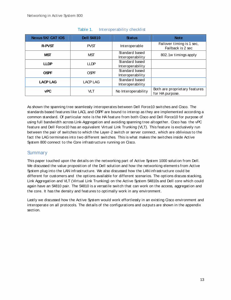
Table 1. Interoperability checklist
Nexus 5K/ CAT IOS Dell S4810 Status Note
R-PVST PVST Interoperable Failover timing is 1 sec, Failback is 2 sec
MST MST Standard based Interoperability 802.1w timings apply
LLDP LLDP Standard based Interoperability
OSPF OSPF Standard based Interoperability
LACP LAG LACP LAG Standard based Interoperability
vPC VLT No Interoperability Both are proprietary features for HA purpose.
As shown the spanning tree seamlessly interoperates between Dell Force10 switches and Cisco. The standards based features like LACL and OSPF are bound to interop as they are implemented according a common standard. Of particular note is the HA feature from both Cisco and Dell Force10 for purpose of using full bandwidth across Link-Aggregation and avoiding spanning tree altogether. Cisco has the vPC feature and Dell Force10 has an equivalent Virtual Link Trunking (VLT). This feature is exclusively run between the pair of switches to which the Layer-2 switch or server connect, which are oblivious to the fact the LAG terminates into two different switches. This is what makes the switches inside Active System 800 connect to the Core infrastructure running on Cisco.
Summary
This paper touched upon the details on the networking part of Active System 1000 solution from Dell. We discussed the value proposition of the Dell solution and how the networking elements from Active System plug into the LAN infrastructure. We also discussed how the LAN infrastructure could be different for customers and the options available for different scenarios. The options discuss stacking, Link Aggregation and VLT (Virtual Link Trunking) on the Active System S4810s and Dell core which could again have an S4810 pair. The S4810 is a versatile switch that can work on the access, aggregation and the core. It has the density and features to optimally work in any environment.
Lastly we discussed how the Active System would work effortlessly in an existing Cisco environment and interoperate on all protocols. The details of the configurations and outputs are shown in the appendix section.

Networking in Active System 800
14
Appendix
Dell S4810 Core with VLT configuration
Following CLI and output snippets are from Dell Force10 S4810 as the core running VLT and the Active System connected to this core.
Following these steps we will configure VLT on the pair of S4810s that interconnect the racks. To configure virtual link trunking, you must create a VLT domain, configure a backup link and interconnect trunk, and connect the peer switches in a VLT domain to an attached access device (switch or server).
Figure 10. S4810 VLT interconnect
Before this, RSTP should be configured as a best practice on the S4810 as well as the S60s.
Force10_VLTpeer1(conf)#protocol spanning-tree rstp Force10_VLTpeer1(conf-rstp)#no disable Force10_VLTpeer1(conf-rstp)#bridge-priority 4096 #Repeat the same on VLTPeer2 with a different bridge priority to make it the root. Force10_VLTpeer2(conf-rstp)#bridge-priority 0
The next figures show a sample VLT configuration. VLT works over an ICL or primary link and a backup link. In absence of a direct path to the destination, the ICL link would carry the traffic to the peer. The backup link is only for heartbeat status from the peer and no data traffic flows over it.
Configure a VLT domain
vlt domain <domain id >
Fix the VLT system parameters to avoid negotiations (for faster convergence)
primary-priority <value> (suggestion: 1 for the primary, 8192 for sec) system-mac mac-address <value> (same MAC address on all VLT peers) unit-id <value> (suggestion: 0 for the primary, 1 for secondary)
Avoid picking a random MAC addresses that could be reserved or multicast.
Prepare your port-channel for VLTi (interconnect) configuration. To become a VLTi the port-channel should be in default mode (no switchport).

Networking in Active System 800
15
Note: The system will automatically include needed VLANs to be tagged into the VLTi. You do not need to manually tag VLANs on the VLTi.
Configure the core VLT peering relationship across the port-channel that will become the VLT interconnect (VLTi)
Note: it is recommended to build the VLTi port-channel statically to minimize negotiations in the VLT domain core.
(conf-vlt-domain)# peer-link port-channel <LAG-ID>
Configure the VLT backup link (used for health checks)
(conf-vlt-domain)# back-up destination <ip-address>
The backup link should be a different link than the VLTi and if possible following a diverse path. This could be the management interface IP address.
Note: It is recommended that VLTs that are facing hosts/switches should be preferably built by LACP, to benefit from the protocol negotiations. However static port-channels are also supported
interface port-channel <id-number> vlt-peer-lag port-channel <id-number>
Sample VLT configuration on peer1 Force10_VLTpeer1(conf)#vlt domain 999 Force10_VLTpeer1(conf-vlt-domain)#peer-link port-channel 100 Force10_VLTpeer1(conf-vlt-domain)#back-up destination 10.11.206.35
Force10_VLTpeer1(conf-vlt-domain)#exit Force10_VLTpeer1(conf)#interface ManagementEthernet 0/0
Force10_VLTpeer1(conf-if-ma-0/0)#ip address 10.11.206.23/16
Force10_VLTpeer1(conf-if-ma-0/0)#no shutdown Force10_VLTpeer1(conf-if-ma-0/0)#exit Force10_VLTpeer1(conf)#interface port-channel 100 Force10_VLTpeer1(conf-if-po-100)#no ip address Force10_VLTpeer1(conf-if-po-100)#channel-member fortyGigE 0/56,60 Force10_VLTpeer1(conf-if-po-100)#no shutdown Force10_VLTpeer1(conf-if-po-100)#exit Force10_VLTpeer1(conf)#interface port-channel 110 Force10_VLTpeer1(conf-if-po-110)#no ip address Force10_VLTpeer1(conf-if-po-110)#switchport Force10_VLTpeer1(conf-if-po-110)#channel-member fortyGigE 0/52 Force10_VLTpeer1(conf-if-po-110)#no shutdown Force10_VLTpeer1(conf-if-po-110)#vlt-peer-lag port-channel 110 Force10_VLTpeer1(conf-if-po-110)#end

Networking in Active System 800
16
Force10_VLTpeer1# show vlan id 10 Codes: * - Default VLAN, G - GVRP VLANs, P - Primary, C - Community, I - Isolated Q: U - Untagged, T - Tagged x - Dot1x untagged, X - Dot1x tagged G - GVRP tagged, M - Vlan-stack, H - Hyperpull tagged NUM Status Description Q Ports 10 Active U Po110(Fo 0/52) T Po100(Fo 0/56,60)
S4810 inside Active System The S4810 inside Active System is configured exactly the same as the one with Cisco core. See below for a sample config. The only difference in this case would be the Spanning-Tree Root Bridge would lie on the VLT master S4810 of the core.
Cisco Nexus 5548 Core with vPC configuration
Following CLI and output snippets are from a Cisco Nexus 5548 operating as the core, running vPC and the Active System connected to this core.
S4810 inside Active System ###########Configuration-S4810-01##### protocol spanning-tree pvst no disable
! interface Port-channel 12 no ip address mtu 2500 portmode hybrid switchport no shutdown ! interface TenGigabitEthernet 0/49 no ip address mtu 2500
! port-channel-protocol LACP port-channel 12 mode active no shutdown ! interface TenGigabitEthernet 0/50 no ip address mtu 2500
! port-channel-protocol LACP port-channel 12 mode active no shutdown ! interface TenGigabitEthernet 0/51 no ip address
###########Configuration-S4810-02#### protocol spanning-tree pvst no disable
! interface Port-channel 11 no ip address mtu 2500 portmode hybrid switchport no shutdown ! interface TenGigabitEthernet 0/49 no ip address mtu 2500
! port-channel-protocol LACP port-channel 11 mode active no shutdown ! interface TenGigabitEthernet 0/50 no ip address mtu 2500 ! port-channel-protocol LACP port-channel 11 mode active no shutdown ! interface TenGigabitEthernet 0/51 no ip address

Networking in Active System 800
17
mtu 2500
! port-channel-protocol LACP port-channel 12 mode active no shutdown ! interface TenGigabitEthernet 0/52 no ip address mtu 2500
! port-channel-protocol LACP port-channel 12 mode active no shutdown ! interface Vlan 11 no ip address mtu 2500 tagged Port-channel 12 no shutdown ! interface Vlan 12 no ip address mtu 2500 tagged Port-channel 12 no shutdown ! interface Vlan 20 no ip address mtu 2500 !untagged TenGigabitEthernet 0/1-32 !untagged Port-channel 1,10,12 no shutdown !
mtu 2500 ! port-channel-protocol LACP port-channel 11 mode active no shutdown ! interface TenGigabitEthernet 0/52 no ip address mtu 2500 ! port-channel-protocol LACP port-channel 11 mode active no shutdown
! interface Vlan 11 no ip address mtu 2500 tagged Port-channel 11 no shutdown ! interface Vlan 12 ip address 10.11.1.2/24 mtu 2500 tagged Port-channel 11 no shutdown ! interface Vlan 20 no ip address mtu 2500 !untagged TenGigabitEthernet 0/1-16 !untagged Port-channel 11,20 no shutdown !
############## LLDP Connections##################### S4810_01#sho lldp neighbors Loc PortID Rem Host Name Rem Port Id Rem Chassis Id ------------------------------------------------------------------------- Te 0/49 Nexus5548-Botto...Eth1/2 54:7f:ee:53:3e:89 Te 0/50 Nexus5548-Botto...Eth1/1 54:7f:ee:53:3e:88 Te 0/51 Nexus5548-Top Eth1/2 54:7f:ee:56:55:49 Te 0/52 Nexus5548-Top Eth1/1 54:7f:ee:56:55:48 ############## S4810-02#sho lldp neighbors Loc PortID Rem Host Name Rem Port Id Rem Chassis Id -------------------------------------------------------------------------
Te 0/49 Nexus5548-Botto...Eth1/26 54:7f:ee:53:3e:a1 Te 0/50 Nexus5548-Botto...Eth1/25 54:7f:ee:53:3e:a0 Te 0/51 Nexus5548-Top Eth1/26 54:7f:ee:56:55:61 Te 0/52 Nexus5548-Top Eth1/25 54:7f:ee:56:55:60
Networking in Active System 800
18
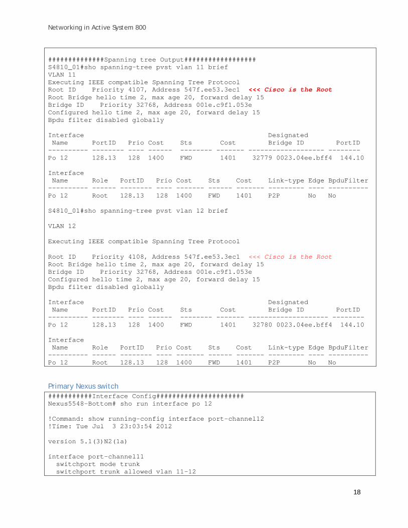
##############Spanning tree Output################## S4810_01#sho spanning-tree pvst vlan 11 brief VLAN 11 Executing IEEE compatible Spanning Tree Protocol Root ID Priority 4107, Address 547f.ee53.3ec1 <<< Cisco is the Root Root Bridge hello time 2, max age 20, forward delay 15 Bridge ID Priority 32768, Address 001e.c9f1.053e Configured hello time 2, max age 20, forward delay 15 Bpdu filter disabled globally Interface Designated Name PortID Prio Cost Sts Cost Bridge ID PortID ---------- -------- ---- ------ -------- ------- ------------------- -------- Po 12 128.13 128 1400 FWD 1401 32779 0023.04ee.bff4 144.10 Interface Name Role PortID Prio Cost Sts Cost Link-type Edge BpduFilter ---------- ------ -------- ---- ------- ------ ------- --------- ---- ---------- Po 12 Root 128.13 128 1400 FWD 1401 P2P No No S4810_01#sho spanning-tree pvst vlan 12 brief
VLAN 12
Executing IEEE compatible Spanning Tree Protocol
Root ID Priority 4108, Address 547f.ee53.3ec1 <<< Cisco is the Root Root Bridge hello time 2, max age 20, forward delay 15 Bridge ID Priority 32768, Address 001e.c9f1.053e Configured hello time 2, max age 20, forward delay 15 Bpdu filter disabled globally Interface Designated Name PortID Prio Cost Sts Cost Bridge ID PortID ---------- -------- ---- ------ -------- ------- -------------------- -------- Po 12 128.13 128 1400 FWD 1401 32780 0023.04ee.bff4 144.10 Interface Name Role PortID Prio Cost Sts Cost Link-type Edge BpduFilter ---------- ------ -------- ---- ------- ------ ------- --------- ---- ---------- Po 12 Root 128.13 128 1400 FWD 1401 P2P No No
Primary Nexus switch ###########Interface Config###################### Nexus5548-Bottom# sho run interface po 12 !Command: show running-config interface port-channel12 !Time: Tue Jul 3 23:03:54 2012 version 5.1(3)N2(1a) interface port-channel11 switchport mode trunk switchport trunk allowed vlan 11-12
Networking in Active System 800
19
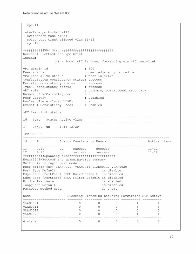
vpc 11 interface port-channel12 switchport mode trunk switchport trunk allowed vlan 11-12 vpc 12 ###########VPC Status########################## Nexus5548-Bottom# sho vpc brief Legend: (*) - local vPC is down, forwarding via vPC peer-link vPC domain id : 500 Peer status : peer adjacency formed ok vPC keep-alive status : peer is alive Configuration consistency status: success Per-vlan consistency status : success Type-2 consistency status : success vPC role : primary, operational secondary Number of vPCs configured : 2 Peer Gateway : Disabled Dual-active excluded VLANs : - Graceful Consistency Check : Enabled vPC Peer-link status --------------------------------------------------------------------- id Port Status Active vlans -- ---- ------ -------------------------------------------------- 1 Po500 up 1,11-12,20 vPC status ---------------------------------------------------------------------------- id Port Status Consistency Reason Active vlans ------ ----------- ------ ----------- -------------------------- ----------- 11 Po11 up success success 11-12 12 Po12 up success success 11-12 ###########Spanning tree######################## Nexus5548-Bottom# sho spanning-tree summary Switch is in rapid-pvst mode Root bridge for: VLAN0001, VLAN0011-VLAN0012, VLAN0020 Port Type Default is disable Edge Port [PortFast] BPDU Guard Default is disabled Edge Port [PortFast] BPDU Filter Default is disabled Bridge Assurance is enabled Loopguard Default is disabled Pathcost method used is short Name Blocking Listening Learning Forwarding STP Active ---------------------- -------- --------- -------- ---------- ---------- VLAN0001 0 0 0 1 1 VLAN0011 0 0 0 3 3 VLAN0012 0 0 0 3 3 VLAN0020 0 0 0 1 1 ---------------------- -------- --------- -------- ---------- ---------- 4 vlans 0 0 0 8 8

Networking in Active System 800
20
##############VPC Config######################## Nexus5548-Bottom# sho run vpc !Command: show running-config vpc !Time: Tue Jul 3 23:07:14 2012 version 5.1(3)N2(1a) feature vpc vpc domain 500 peer-keepalive destination 172.25.188.60 source 172.25.188.61 ip arp synchronize interface port-channel11 vpc 11 interface port-channel12 vpc 12 interface port-channel500 vpc peer-link
Secondary Nexus switch ###########Interface Config###################### Nexus5548-Top# sho run interface port-channel 11 !
interface port-channel11 switchport mode trunk switchport trunk allowed vlan 11-12 vpc 11 !
interface port-channel12 switchport mode trunk switchport trunk allowed vlan 11-12 vpc 12 ###########VPC Status########################## Nexus5548-Top# sho vpc brief Legend: (*) - local vPC is down, forwarding via vPC peer-link vPC domain id : 500 Peer status : peer adjacency formed ok vPC keep-alive status : peer is alive Configuration consistency status: success Per-vlan consistency status : success Type-2 consistency status : success vPC role : secondary, operational primary Number of vPCs configured : 2 Peer Gateway : Disabled Dual-active excluded VLANs : - Graceful Consistency Check : Enabled

Networking in Active System 800
21
vPC Peer-link status --------------------------------------------------------------------- id Port Status Active vlans -- ---- ------ -------------------------------------------------- 1 Po500 up 1,11-12,20 vPC status ---------------------------------------------------------------------------- id Port Status Consistency Reason Active vlans ------ ----------- ------ ----------- -------------------------- ----------- 11 Po11 up success success 11-12 12 Po12 up success success 11-12 ###########Spanning tree######################## Nexus5548-Top# sho spanning-tree summary Switch is in rapid-pvst mode Root bridge for: none Port Type Default is disable Edge Port [PortFast] BPDU Guard Default is disabled Edge Port [PortFast] BPDU Filter Default is disabled Bridge Assurance is enabled Loopguard Default is disabled Pathcost method used is short Name Blocking Listening Learning Forwarding STP Active ---------------------- -------- --------- -------- ---------- ---------- VLAN0001 0 0 0 1 1 VLAN0011 0 0 0 3 3 VLAN0012 0 0 0 3 3 VLAN0020 0 0 0 2 2 ---------------------- -------- --------- -------- ---------- ----------