Embed Size (px)
Citation preview
Dell EMC Host Connectivity Guide for Tru64 UNIX
P/N 300-000-616REV 26 This document is not intended for audiences in China, Hong Kong, Taiwan, and Macao.
Copyright © 2003 - 2017 Dell Inc. or its subsidiaries. All rights reserved.
Published June 2017
Dell believes the information in this publication is accurate as of its publication date. The information is subject to change without notice.
THE INFORMATION IN THIS PUBLICATION IS PROVIDED "AS IS." DELL INC. MAKES NO REPRESENTATIONS OR WARRANTIES OF ANY KIND WITH RESPECT TO THE INFORMATION IN THIS PUBLICATION, AND SPECIFICALLY DISCLAIMS IMPLIED WARRANTIES OF MERCHANTABILITY OR FITNESS FOR A PARTICULAR PURPOSE.
Use, copying, and distribution of any Dell EMC software described in this publication requires an applicable software license.
Dell, EMC2, EMC, and the EMC logo are registered trademarks or trademarks of Dell Inc. or its subsidiaries. All other trademarks used herein are the property of their respective owners..
For the most up-to-date regulator document for your product line, go to Dell EMC Online Support (https://support.emc.com).
Dell EMC Host Connectivity Guide for Tru64 UNIX2
CONTENTS
Preface................................................................................................................................................. 11
Part 1 Symmetrix Connectivity
Chapter 1 Tru64 UNIX / Symmetrix Environment
Overview................................................................................................... 18Patches and online documentation ...................................................... 18
Enginuity minimum requirements............................................................... 19Tru64 UNIX commands and utilities........................................................... 21Tru64 UNIX devices................................................................................... 22
Device naming conventions .................................................................22Disk label and device partitions............................................................23
Using file systems ..................................................................................... 24Creating and mounting the UNIX file system .......................................24AdvFS..................................................................................................24Creating and mounting an AdvFS ........................................................24Reconstructing an AdvFS domain....................................................... 25LUN expansion.................................................................................... 25
Logical storage manager ........................................................................... 27Example 1: Setting Up LSM .................................................................27Example 2: Creating a mirrored volume .............................................. 28Example 3: Creating a four-way striped volume.................................. 28
System and error messages ..................................................................... 30
Chapter 2 Virtual Provisioning
Virtual Provisioning on Symmetrix ............................................................. 32Terminology.........................................................................................33Thin device ..........................................................................................34
Implementation considerations.................................................................. 36Over-subscribed thin pools ................................................................. 36Thin-hostile environments ...................................................................37Pre-provisioning with thin devices in a thin hostile environment..........37Host boot/root/swap/dump devices positioned on Symmetrix VP (tdev) devices ............................................................. 38Cluster configurations ........................................................................ 39
Symmetrix Virtual Provisioning in a Tru64 UNIX environment.................... 40Tru64 UNIX Virtual Provisioning support ............................................ 40Precaution considerations .................................................................. 40Unbound thin devices .......................................................................... 41
Chapter 3 Tru64 UNIX and Symmetrix over Fibre Channel
Tru64 UNIX/Symmetrix Fibre Channel environment.................................. 44Hardware connectivity.........................................................................44Boot device support ............................................................................44Logical devices ....................................................................................44Symmetrix configuration .................................................................... 45Port sharing........................................................................................ 46
Dell EMC Host Connectivity Guide for Tru64 UNIX 3
Contents
Host configuration with Compaq HBAs ..................................................... 47Planning zoning and connections.........................................................47Installing the HBA ................................................................................47Configuring boot support.....................................................................47Rebuilding the Tru64 UNIX kernel....................................................... 48Upgrading the Tru64 UNIX Fibre Channel driver................................. 48Adding the Symmetrix device entry .................................................... 49V4.0F/V4.0G notes ............................................................................ 49V5.x notes .......................................................................................... 50
Addressing Symmetrix devices .................................................................. 52Arbitrated loop addressing.................................................................. 52Fabric addressing................................................................................ 53SCSI-3 FCP addressing ...................................................................... 54
Chapter 4 Tru64 UNIX and Symmetrix over SCSI
Symmetrix configuration .......................................................................... 58Host configuration ................................................................................... 59
Installing the HBA .............................................................................. 59Scanning and configuring a boot device.............................................. 59Rebuilding the Tru64 UNIX kernel....................................................... 59Adding the Symmetrix device entry to the ddr.dbase ......................... 60
Device management.................................................................................. 61Adding and managing devices .............................................................. 61
Chapter 5 TruCluster Servers
TruCluster V1.6 overview........................................................................... 64Available Server .................................................................................. 64Production Server .............................................................................. 64TruCluster V1.6 services ..................................................................... 64asemgr................................................................................................ 65TruCluster V1.6 daemons and error logs ............................................. 65
TruCluster V1.6 with Symmetrix ............................................................... 66Symmetrix connectivity ...................................................................... 66Symmetrix configuration .................................................................... 68Additional documentation ................................................................... 68
TruCluster V5.x overview ......................................................................... 69Connection manager........................................................................... 69Device request dispatcher ...................................................................70Cluster File System..............................................................................70Cluster Application Availability............................................................. 71
TruCluster V5.x with Symmetrix ................................................................ 72Symmetrix connectivity .......................................................................72TruCluster V5.x system disk requirements...........................................73Symmetrix configuration .....................................................................74Direct-access device and DRD barrier configuration............................75Persistent reservations........................................................................78Additional documentation ....................................................................78
Part 2 VNX Series and CLARiiON Connectivity
Chapter 6 Tru64 UNIX Hosts with VNX Series and CLARiiON
Tru64 UNIX in a VNX series and CLARiiON environment ........................... 82
4 Dell EMC Host Connectivity Guide for Tru64 UNIX
Contents
Host connectivity ............................................................................... 82Boot device support ........................................................................... 82Logical devices ................................................................................... 82General configuration overview .......................................................... 82
Host configuration with Compaq HBAs ..................................................... 84Installing the HBA ............................................................................... 84Creating an entry in ddr.dbase............................................................ 85Upgrading the Tru64 UNIX Fibre Channel HBA driver......................... 88Rebuilding the Tru64 UNIX kernel....................................................... 88Zoning HBA connections .................................................................... 88Setting the UDID ................................................................................ 88Setting connection properties ............................................................ 89Creating a storage group ..................................................................... 91
Booting from the VNX series and CLARiiON storage system..................... 93Preparatory steps............................................................................... 93Establish preliminary zone .................................................................. 94Create initiator record ........................................................................ 94Binding the boot LUN ......................................................................... 94Preparing the SRM console boot device ............................................. 94Installing Tru64 UNIX.......................................................................... 95Completing zoning.............................................................................. 96Updating connection information........................................................ 96Updating SRM console information .................................................... 96Setting BOOTDEF_DEV ..................................................................... 96
TruCluster configurations and persistent reservations .............................. 98Enabling persistent reservations ......................................................... 98Performing a new TruCluster installation ............................................101
Configuring LUNs on the host ................................................................. 102HBA management.............................................................................. 102Device naming ................................................................................... 102Adding devices .................................................................................. 102LUN trespassing and path failover ..................................................... 103Multipath configurations.................................................................... 104LUN expansion................................................................................... 104
Part 3 Appendix
Appendix A Methods of Data Migration
Tru64 UNIX V5 overview .......................................................................... 110Device naming ................................................................................... 110Disk labels.......................................................................................... 110Logical Storage Manager ................................................................... 110Advanced File System ....................................................................... 111
Data migration methods ........................................................................... 111Migration of file systems using vdump/vrestore................................ 111Migration of AdvFS domains using addvol/rmvol ............................... 113Data migration using LSM mirroring .................................................. 115Storage-based data migration ............................................................116
System and boot device migration............................................................ 118Tru64 UNIX V5 system and boot device migration............................. 118TruCluster V5 system and boot device migration.............................. 120
Related documentation ........................................................................... 135
Dell EMC Host Connectivity Guide for Tru64 UNIX 5

Contents
6 Dell EMC Host Connectivity Guide for Tru64 UNIX
FIGURES
FIGURES
1 Partitioning layout using default disk type ................................................................ 232 Virtual Provisioning on Symmetrix ............................................................................ 323 Thin device and thin storage pool containing data devices ...................................... 354 ASE cluster cabling .................................................................................................. 675 Basic TruCluster V5.x configuration using Symmetrix devices ................................. 736 Storage system properties and the base UUID ........................................................ 897 Connectivity status window .................................................................................... 898 Register Initiator Record window ............................................................................ 909 Storage Group Properties window, General tab ....................................................... 9110 Storage Group Properties window, LUN tab ............................................................ 9211 Storage Group Properties window, Host tab ............................................................ 9212 Storage group properties with host LUN unit ID ...................................................... 95
Dell EMC Host Connectivity Guide for Tru64 UNIX 7

Dell EMC Host Connectivity Guide for Tru64 UNIX8
TABLES
TABLES
1 Minimum Enginuity requirements .............................................................................. 192 Tru64 UNIX commands and utilities .......................................................................... 213 LUN 000 behavior differences ................................................................................. 454 FC-AL addressing parameters .................................................................................. 535 Symmetrix SCSI-3 addressing modes ...................................................................... 556 Tru64 UNIX SCSI device support ............................................................................. 587 Device management commands and utilities ............................................................. 61
Dell EMC Host Connectivity Guide for Tru64 UNIX 9

Tableses
10 Dell EMC Host Connectivity Guide for Tru64 UNIX
PREFACE
As part of an effort to improve and enhance the performance and capabilities of its product line, Dell EMC from time to time releases revisions of its hardware and software. Therefore, some functions described in this document might not be supported by all revisions of the software or hardware currently in use. For the most up-to-date information on product features, refer to your product release notes.
If a product does not function properly or does not function as described in this document, please contact your Dell EMC representative.
This guide describes the features and setup procedures for Tru64 UNIX host interfaces to Dell EMC Symmetrix, EMC VNX series, and CLARiiON storage systems over Fibre Channel or (Symmetrix only) SCSI connections.
Audience This guide is intended for use by storage administrators, system programmers, or operators who are involved in acquiring, managing, or operating Dell EMC Symmetrix, EMC VNX series, and Dell EMC CLARiiON, and host devices.
Readers of this guide are expected to be familiar with the following topics:
◆ Symmetrix, VNX series, and CLARiiON system operation
◆ HP Tru64 UNIX operating environment
Relateddocumentation
Related documents include:
◆ Dell EMC Host Connectivity Guide for True64 UNIX, available on Dell EMC Online Support.
◆ Dell EMC Simple Support Matrix, available on Dell EMC E-Lab Interoperability Navigator.
Note: Always refer to the Dell EMC Simple Support Matrix for the most up-to-date information.
◆ HP Tru64 UNIX online documentation
◆ HP Tru64 UNIX Operating System and TruCluster Patch Kit Documentation
Conventions used inthis guide
Dell EMC uses the following conventions for notes and cautions.
Note: A note presents information that is important, but not hazard-related.
IMPORTANT!An important notice contains information essential to operation of the software.
CAUTION!A caution contains information essential to avoid damage to the system or equipment. The caution may apply to hardware or software.
Dell EMC Host Connectivity Guide for Tru64 UNIX 11
Preface
Typographical conventions
Dell EMC uses the following type style conventions in this guide:
Normal Used in running (nonprocedural) text for:• Names of interface elements (such as names of
windows, dialog boxes, buttons, fields, and menus)• Names of resources, attributes, pools, Boolean
expressions, buttons, DQL statements, keywords, clauses, environment variables, filenames, functions, utilities
• URLs, pathnames, filenames, directory names, computer names, links, groups, service keys, file systems, notifications
Bold: Used in running (nonprocedural) text for:• Names of commands, daemons, options, programs,
processes, services, applications, utilities, kernels, notifications, system call, man pages
Used in procedures for:• Names of interface elements (such as names of
windows, dialog boxes, buttons, fields, and menus)• What user specifically selects, clicks, presses, or
types
Italic: Used in all text (including procedures) for:• Full titles of publications referenced in text• Emphasis (for example a new term)• Variables
Courier: Used for:• System output, such as an error message or script • URLs, complete paths, filenames, prompts, and
syntax when shown outside of running text
Courier bold: Used for:• Specific user input (such as commands)
Courier italic: Used in procedures for:• Variables on command line• User input variables
< > Angle brackets enclose parameter or variable values supplied by the user
[ ] Square brackets enclose optional values
| Vertical bar indicates alternate selections - the bar means “or”
{ } Braces indicate content that you must specify (that is, x or y or z)
... Ellipses indicate nonessential information omitted from the example
12 Dell EMC Host Connectivity Guide for Tru64 UNIX
Preface
Where to get help Dell EMC support, product, and licensing information can be obtained on the Dell EMC Online Support site as described next.
Note: To open a service request through the Dell EMC Online Support site, you must have a valid support agreement. Contact your Dell EMC sales representative for details about obtaining a valid support agreement or to answer any questions about your account.
Product information
For documentation, release notes, software updates, or for information about Dell EMC products, licensing, and service, go to Dell EMC Online Support (registration required).
Technical support
Dell EMC offers a variety of support options.
Support by Product — Dell EMC offers consolidated, product-specific information on the Web at Dell EMC Online Support.
The Support by Product web pages offer quick links to Documentation, White Papers, Advisories (such as frequently used Knowledgebase articles), and Downloads, as well as more dynamic content, such as presentations, discussion, relevant Customer Support Forum entries, and a link to Dell EMC Live Chat.
Dell EMC Live Chat — Open a Chat or instant message session with an Dell EMC Support Engineer.
eLicensing support
To activate your entitlements and obtain your Symmetrix license files, visit the Service Center on Dell EMC Online Support, as directed on your License Authorization Code (LAC) letter e-mailed to you.
For help with missing or incorrect entitlements after activation (that is, expected functionality remains unavailable because it is not licensed), contact your Dell EMC Account Representative or Authorized Reseller.
For help with any errors applying license files through Solutions Enabler, contact the Dell EMC Customer Support Center.
Dell EMC Host Connectivity Guide for Tru64 UNIX 13
Preface
If you are missing a LAC letter, or require further instructions on activating your licenses through the Online Support site, contact Dell EMC's worldwide Licensing team at [email protected] or call:
◆ North America, Latin America, APJK, Australia, New Zealand: SVC4EMC (800-782-4362) and follow the voice prompts.
◆ EMEA: +353 (0) 21 4879862 and follow the voice prompts.
We'd like to hear from you!
Your suggestions will help us continue to improve the accuracy, organization, and overall quality of the user publications. Send your opinions of this document to:
Your feedback on our TechBooks is important to us! We want our books to be as helpful and relevant as possible. Send us your comments, opinions, and thoughts on this or any other TechBook to:
14 Dell EMC Host Connectivity Guide for Tru64 UNIX
PART 1
Part 1 includes:
◆ Chapter 1, ”Tru64 UNIX / Symmetrix Environment”
◆ Chapter 2, ”Virtual Provisioning”
◆ Chapter 3, ”Tru64 UNIX and Symmetrix over Fibre Channel”
◆ Chapter 4, ”Tru64 UNIX and Symmetrix over SCSI”
◆ Chapter 5, ”TruCluster Servers”
Symmetrix Connectivity

CHAPTER 1
This chapter provides an overview of the Tru64 UNIX environment. Tru64 UNIX is a Hewlett-Packard (HP) operating system (formerly a product of Compaq and Digital Equipment Corporation).
◆ Overview............................................................................................. 18◆ Enginuity minimum requirements.................................................. 19◆ Tru64 UNIX commands and utilities .............................................. 21◆ Tru64 UNIX devices........................................................................... 22◆ Using file systems .............................................................................. 24◆ Logical storage manager................................................................... 27◆ System and error messages .............................................................. 30
Tru64 UNIX / Symmetrix Environment
Tru64 UNIX / Symmetrix Environment 17
Tru64 UNIX / Symmetrix Environment
OverviewWhen using an Dell EMC™ Symmetrix™ system in the Tru64 UNIX environment, note the following:
◆ The minimum version of Tru64 UNIX supported is V4.0F.
◆ The latest information regarding any restrictions, exceptions, firmware/driver versions, and requirements is listed in the Dell EMC Simple Support Matrix.
Note: Always refer to the Dell EMC Simple Support Matrix for the most up-to-date information.
Patches and online documentation
Patches for Tru64 UNIX are available at HP Tru64 UNIX Operating System and TruCluster Patch Kit Documentation.
Find Tru64 UNIX online documentation on the Tru64 UNIX Online Documentation and Reference Pages.
18 Dell EMC Host Connectivity Guide for Tru64 UNIX
Tru64 UNIX / Symmetrix Environment
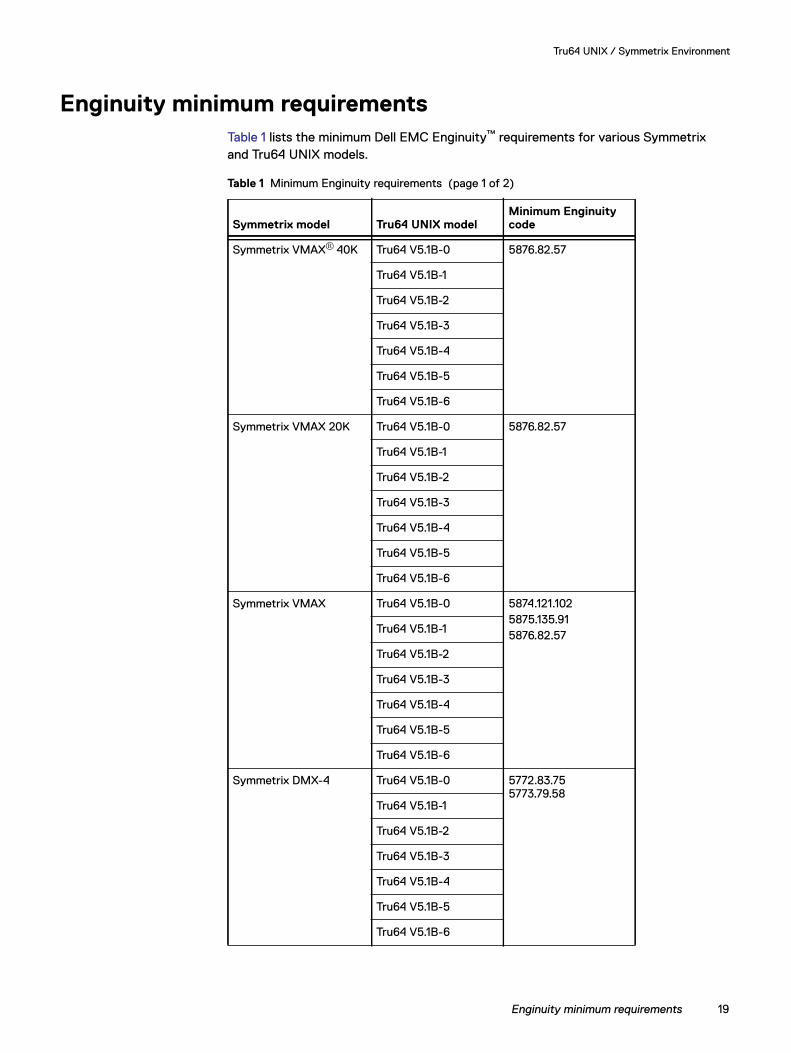
Enginuity minimum requirementsTable 1 lists the minimum Dell EMC Enginuity™ requirements for various Symmetrix and Tru64 UNIX models.
Table 1 Minimum Enginuity requirements (page 1 of 2)
Symmetrix model Tru64 UNIX modelMinimum Enginuity code
Symmetrix VMAX® 40K Tru64 V5.1B-0 5876.82.57
Tru64 V5.1B-1
Tru64 V5.1B-2
Tru64 V5.1B-3
Tru64 V5.1B-4
Tru64 V5.1B-5
Tru64 V5.1B-6
Symmetrix VMAX 20K Tru64 V5.1B-0 5876.82.57
Tru64 V5.1B-1
Tru64 V5.1B-2
Tru64 V5.1B-3
Tru64 V5.1B-4
Tru64 V5.1B-5
Tru64 V5.1B-6
Symmetrix VMAX Tru64 V5.1B-0 5874.121.1025875.135.915876.82.57Tru64 V5.1B-1
Tru64 V5.1B-2
Tru64 V5.1B-3
Tru64 V5.1B-4
Tru64 V5.1B-5
Tru64 V5.1B-6
Symmetrix DMX-4 Tru64 V5.1B-0 5772.83.75 5773.79.58
Tru64 V5.1B-1
Tru64 V5.1B-2
Tru64 V5.1B-3
Tru64 V5.1B-4
Tru64 V5.1B-5
Tru64 V5.1B-6
Enginuity minimum requirements 19
Tru64 UNIX / Symmetrix Environment
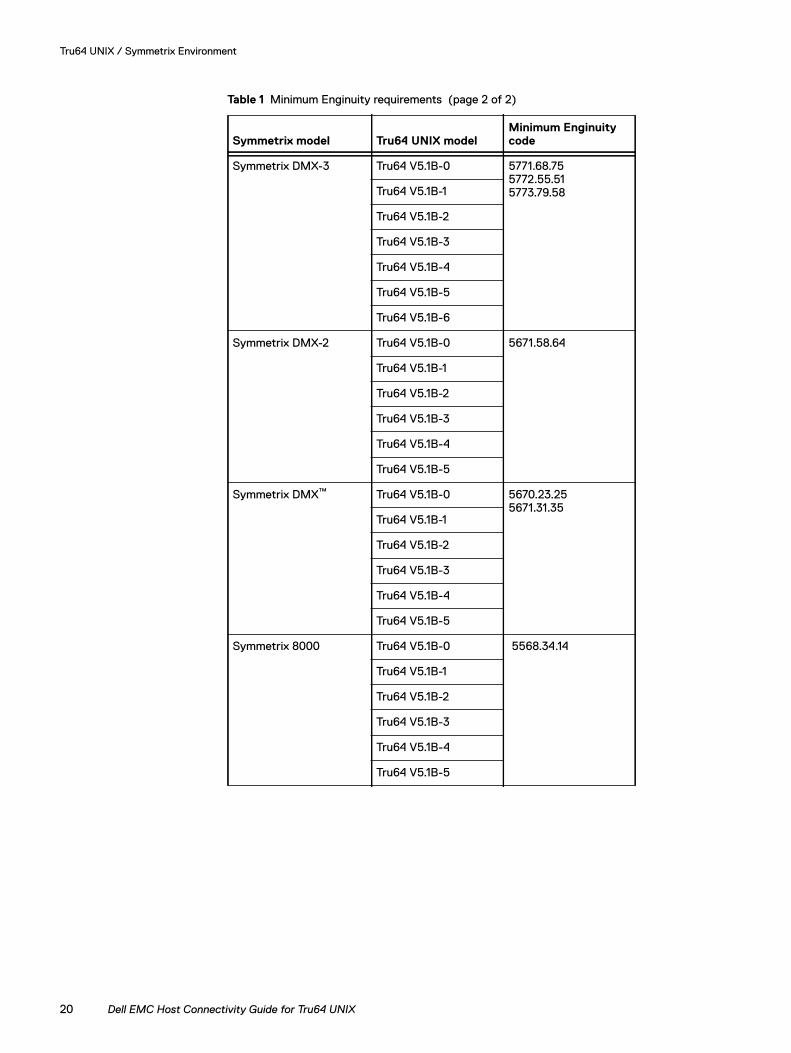
Symmetrix DMX-3 Tru64 V5.1B-0 5771.68.75 5772.55.51 5773.79.58Tru64 V5.1B-1
Tru64 V5.1B-2
Tru64 V5.1B-3
Tru64 V5.1B-4
Tru64 V5.1B-5
Tru64 V5.1B-6
Symmetrix DMX-2 Tru64 V5.1B-0 5671.58.64
Tru64 V5.1B-1
Tru64 V5.1B-2
Tru64 V5.1B-3
Tru64 V5.1B-4
Tru64 V5.1B-5
Symmetrix DMX™ Tru64 V5.1B-0 5670.23.25 5671.31.35
Tru64 V5.1B-1
Tru64 V5.1B-2
Tru64 V5.1B-3
Tru64 V5.1B-4
Tru64 V5.1B-5
Symmetrix 8000 Tru64 V5.1B-0 5568.34.14
Tru64 V5.1B-1
Tru64 V5.1B-2
Tru64 V5.1B-3
Tru64 V5.1B-4
Tru64 V5.1B-5
Table 1 Minimum Enginuity requirements (page 2 of 2)
Symmetrix model Tru64 UNIX modelMinimum Enginuity code
20 Dell EMC Host Connectivity Guide for Tru64 UNIX
Tru64 UNIX / Symmetrix Environment
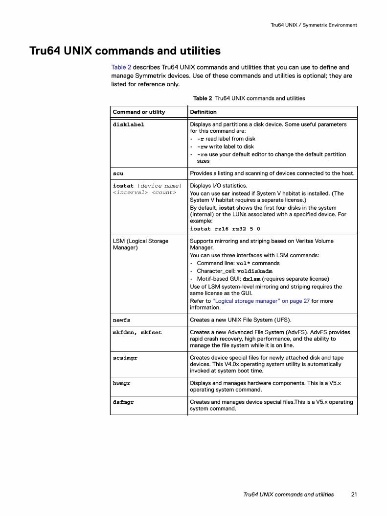
Tru64 UNIX commands and utilitiesTable 2 describes Tru64 UNIX commands and utilities that you can use to define and manage Symmetrix devices. Use of these commands and utilities is optional; they are listed for reference only.
Table 2 Tru64 UNIX commands and utilities
Command or utility Definition
disklabel Displays and partitions a disk device. Some useful parameters for this command are:• -r read label from disk• -rw write label to disk• -re use your default editor to change the default partition
sizes
scu Provides a listing and scanning of devices connected to the host.
iostat [device name]<interval> <count>
Displays I/O statistics.You can use sar instead if System V habitat is installed. (The System V habitat requires a separate license.)By default, iostat shows the first four disks in the system (internal) or the LUNs associated with a specified device. For example:iostat rz16 rz32 5 0
LSM (Logical Storage Manager)
Supports mirroring and striping based on Veritas Volume Manager.You can use three interfaces with LSM commands:• Command line: vol* commands• Character_cell: voldiskadm• Motif-based GUI: dxlsm (requires separate license)Use of LSM system-level mirroring and striping requires the same license as the GUI.Refer to “Logical storage manager” on page 27 for more information.
newfs Creates a new UNIX File System (UFS).
mkfdmn, mkfset Creates a new Advanced File System (AdvFS). AdvFS provides rapid crash recovery, high performance, and the ability to manage the file system while it is on line.
scsimgr Creates device special files for newly attached disk and tape devices. This V4.0x operating system utility is automatically invoked at system boot time.
hwmgr Displays and manages hardware components. This is a V5.x operating system command.
dsfmgr Creates and manages device special files.This is a V5.x operating system command.
Tru64 UNIX commands and utilities 21
Tru64 UNIX / Symmetrix Environment
Tru64 UNIX devicesThis section describes device naming and partitioning conventions in the Tru64 UNIX environment.
Device naming conventions
V4.0x In the 4.0x versions of the Tru64 UNIX operating system, device names (device special files) are determined by bus-target-LUN location, in this format:
rz[lun][unit][partition]
where:
[lun] is a letter ranging from b to h, corresponding to LUNs 1 through 7. For LUN 0, the LUN letter is omitted.
[unit] is bus number * 8 + target ID number.
[partition] is the letter of the disk partition, from a to h.
Example:
/dev/rrzb16c is the raw device name for partition c of the disk at bus 2 target 0 LUN 1.
/dev/rz28h is the block device name for partition h of the disk at bus 3 target 4 LUN 0.
V5.x In the 5.x versions of the Tru64 UNIX operating system, device names (device special files) are only created for device LUNs that report unique device identifiers, and not for every bus-target-LUN instance visible to the system. If the same device identifier (WWID) is reported from multiple bus-target-LUN instances, Tru64 will only create one device name for what it considers to be one unique device. Tru64 V5.x can support multipath configurations and provide path failover and load balancing to devices. The bus-target-LUN paths that reported the same WWID are grouped together as the available paths of a device. The device names in Tru64 UNIX V5.x have the following format:
dsk[unit][partition]
where:
[unit] is a number assigned sequentially to new devices (with unique WWIDs) when they are discovered and configured by the operating system.
[partition] is the letter of the disk partition, from a to h.
Example:
/dev/rdisk/dsk2c is the raw device name for partition c of the second unique device configured by the host.
/dev/disk/dsk853g is the block device name for partition g of the eight hundred fifty third unique device configured.
22 Dell EMC Host Connectivity Guide for Tru64 UNIX
Tru64 UNIX / Symmetrix Environment
Note: With the WWID-based device naming in Tru64 V5.x, a device will retain its original device name (device special file) even if moved to a different adapter/bus location or assigned a new target or LUN address. If an existing device is replaced by a new Symmetrix logical device at the same exact bus-target-LUN, the new device will have a new device name because its WWID will be different.
Disk label and device partitions
Before using specific device partitions, file systems, or LSM, devices should be labeled and partitioned with the disklabel utility.
For example:
◆ Clear or zero out any existing label:
disklabel -z dsk853
◆ Label the disk using default or unknown, as follows:
disklabel -rw dsk853 default
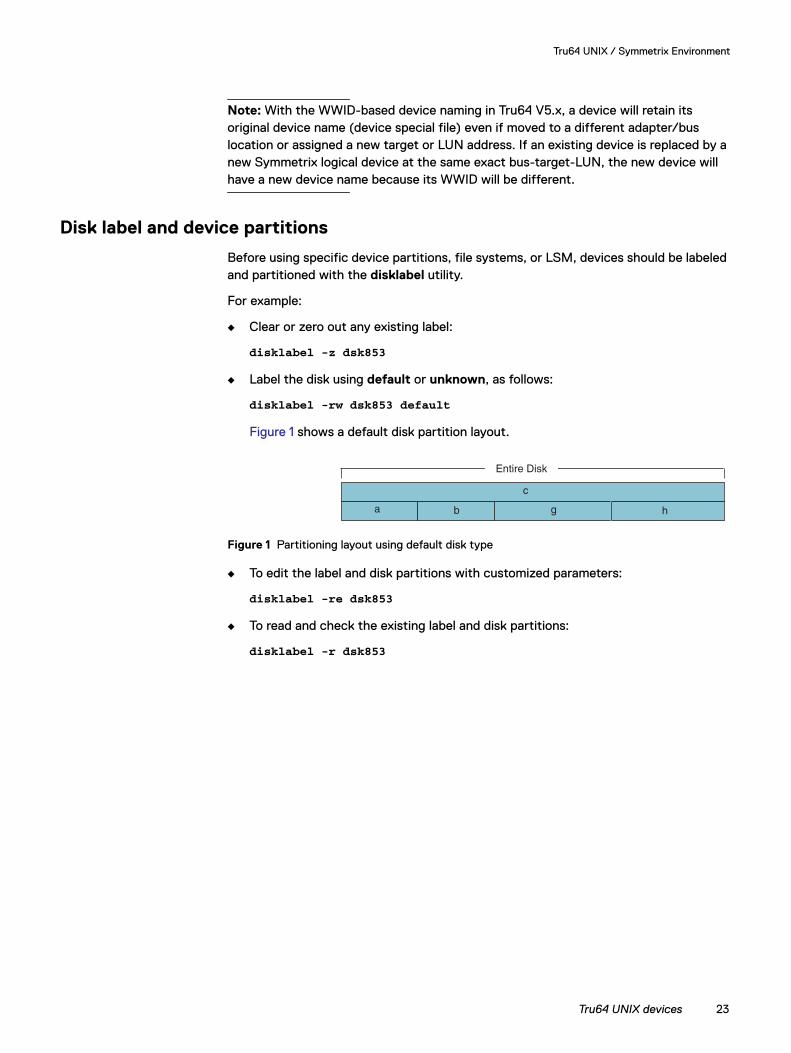
Figure 1 shows a default disk partition layout.
Figure 1 Partitioning layout using default disk type
◆ To edit the label and disk partitions with customized parameters:
disklabel -re dsk853
◆ To read and check the existing label and disk partitions:
disklabel -r dsk853
g ha b
c
Entire Disk
Tru64 UNIX devices 23
Tru64 UNIX / Symmetrix Environment
Using file systemsThis section describes how to use Tru64 UNIX file systems.
Creating and mounting the UNIX file system
To create a new file system on each Symmetrix disk or disk partition:
1. Use the newfs command in a statement similar to the following:
newfs /dev/rz3c
2. Create a directory:
mkdir /symm
3. Mount the file system by typing a statement similar to the following:
mount /dev/rz3c /symm
4. Assign the ownership:
chown oracle:dba /symm
Use the df command to show all mounted file systems and the available free space.
AdvFS
Understanding the following concepts prepares you for planning, creating, and maintaining an Advanced File System (AdvFS).
Volumes A volume is any mechanism that behaves like a UNIX block device, such as a logical volume that is configured with the LSM or a disk partition.
File domain A file domain is a named set of one or more volumes that provides a shared storage pool for one or more filesets.
When you create a file domain using the mkfdmn command, you must specify a domain name and one initial volume. The mkfdmn command creates a subdirectory in the /etc/fdmns directory for each new file domain. The file domain subdirectory contains a symbolic link to the initial volume.
You can add additional volumes to an existing file domain by using the addvol utility. With each added volume, addvol creates a new symbolic link in the appropriate file domain subdirectory of /etc/fdmns.
Filesets A fileset is both the logical file structure that the user recognizes and a unit that you can mount. Whereas you typically mount a whole UNIX file system, with the AdvFS you mount the individual filesets of a file domain.
An AdvFS consists of a file domain with at least one fileset that you create using the mkfset command.
Creating and mounting an AdvFS
To create an AdvFS domain and fileset for each Symmetrix disk:
1. Create a new file domain; for example:
24 Dell EMC Host Connectivity Guide for Tru64 UNIX
Tru64 UNIX / Symmetrix Environment
mkfdmn /dev/rz112c domain1
2. Create a fileset in the domain created in step 1:
mkfset domain1 fileset1
3. Create a directory:
mkdir /symm1
4. Mount the AdvFS fileset by entering a command similar to the following:
mount -t advfs domain1#fileset1 /symm1
Note: A BCV device can be mounted on the same host by specifying the option mount -o dual.
5. Assign the ownership:
chown oracle:dba /symm1
To mount a directory for an AdvFS each time the system boots:
1. Edit /etc/fstab:
vi /etc/fstab
2. Specify each file system to mount using a statement similar to the following:
domain1#fileset1 /symm1 advfs rwUse the df command to show all mounted file systems and the available free space.
Reconstructing an AdvFS domain
If a device with an existing AdvFS file system is newly added to a Tru64 host, follow these steps to create a new AdvFS domain directory and device link:
1. Verify that the new device is a valid AdvFS volume by checking the partition fstype; for example:
disklabel -r dsk1355
2. Re-create (if necessary) and change to the domain directory:
mkdir /etc/fdmns/<domain_name>cd /etc/fdmns/<domain_name>
3. Reconstruct the device link(s) of the AdvFS domain using the new device special file(s):
ln -s /dev/disk/dsk1355c
You can also use the advscan command to reconstruct AdvFS domains.
LUN expansion
The AdvFS and UFS file systems on Tru64 UNIX can support expanded LUNs. AdvFS file systems can be extended on hosts with Tru64 UNIX V5.1B or later installed. UFS file systems can be extended on hosts with Tru64 UNIX V5.1 or later installed.
Using file systems 25
Tru64 UNIX / Symmetrix Environment
The disk label of an expanded LUN must be updated before the new capacity can be used by file systems. Disk partition sizes can be increased to the new capacity, but the disk offsets of in-use disk partitions must not be changed. The disk label updates should only be done by experienced system administrators. Partitioning and sizing errors in disk label updates can cause data loss. A data backup is recommended before expanding a LUN.
The steps for file system LUN expansion are:
1. Back up data on the LUN to be expanded.
2. Save a copy of the existing disk label:
disklabel -r <dsk_name> > disklabel.orig.out
3. Expand the Symmetrix LUN.
4. Reread the disk label or run inq to query the new LUN capacity:
disklabel -r <dsk_name>
5. Rewrite or edit the existing disk label to reflect the new LUN capacity. Increase the size of the disk partition containing the file system to be extended. Do not change the offsets of any disk partitions that are used or open:
disklabel -w <dsk_name>disklabel -re <dsk_name>
6. Extend the file system by remounting with the extend option:
mount -u -o extend <filesystem> <mountpoint>
26 Dell EMC Host Connectivity Guide for Tru64 UNIX
Tru64 UNIX / Symmetrix Environment
Logical storage managerThis section describes three ways of using LSM (a Veritas Volume Manager):
◆ “Example 1: Setting Up LSM,” next
◆ “Example 2: Creating a mirrored volume” on page 28
◆ “Example 3: Creating a four-way striped volume” on page 28
Example 1: Setting Up LSM
This example takes you through the steps for setting up LSM the first time.
1. Use the volsetup command to add disks to your setup. For example:
volsetup rz16 rzb32 rzb40
These three disks are added to your setup as disk01, disk02, and disk03.
2. To add more disks:
• For an entire disk, type a command similar to the following:
voldiskadd rzb16
This command adds the entire disk as disk04.
• For certain partitions, type a command similar to the following:
voldiskadd rzc16g
This command adds the disk partition as disk05.
3. To create a volume on a disk:
• To create a 100 MB volume on disk01, type a command similar to the following:
volassist make myvol1 100m disk01
• To create a 100 MB volume anywhere but on disk02, type a command similar to the following:
volassist make myvol2 100m !disk02
• To create a 10 GB volume anywhere (in rootdg), type a command similar to the following:
volassist make mybigvol 10gb
UNIX file system To create a UNIX file system on a volume:
1. To put a UFS on a 10 GB volume, type a command similar to the following:
newfs /dev/rvol/rootdg/mybigvol
2. To mount a volume type a command similar to the following:
mount /dev/vol/rootdg/mybigvol /symm
Advanced file system To create a new AdvFS on a volume:
1. To create a new AdvFS domain, type a command similar to the following:
mkfdmn /dev/vol/rootdg/mybigvol domain1
Logical storage manager 27
Tru64 UNIX / Symmetrix Environment
2. To create a new fileset, type a command similar to the following:
mkfset domain1 fset1
3. To mount the fileset, type a command similar to the following:
mount -t advfs domain1#fset1 /symm
Example 2: Creating a mirrored volume
This example demonstrates a bottom-up approach to create a mirrored (two-way) volume.
1. Create two subdisks (for example, sd1 and sd2) by typing the following commands. The subdisks in this example are 100 MB in size and start at offset 0 of each disk.
volmake sd sd1 rzb16,0,100mvolmake sd sd2 rzb32,0,100m
2. Create a plex on each subdisk by typing commands similar to the following:
volmake plex plx1 sd-sd1volmake plex plx2 sd-sd2
3. Create a mirrored volume by typing a command similar to the following:
volmake -U gen vol vol01 plex=plx1,plx2
Note: An unmirrored volume consists of one plex. A two-way mirrored volume consists of two plexes. A three-way mirrored volume consists of three plexes. LSM supports up to eight-way mirrors.
4. Start the volume by typing a command similar to the following:
volume start vol01
Note: This command takes some time as it synchronizes both plexes.
Use the volprint command to view the result of these commands:
volprint -ht s-vol
To set volume attributes and make them permanent for an LSM volume, type this command:
voledit set user=oracle group=dba mode=0640 vol01
Example 3: Creating a four-way striped volume
This example demonstrates a bottom-up approach to create a four-way striped volume with a striped width of 64 K.
1. Create four subdisks (for example, of 500 MB each starting at offset 0 of each disk) by typing the following commands:
volmake sd s1-sd rz16,0,500mvolmake sd s2-sd rz32,0,500mvolmake sd s3-sd rz40,0,500m
28 Dell EMC Host Connectivity Guide for Tru64 UNIX
Tru64 UNIX / Symmetrix Environment
volmake sd s4-sd rz48,0,500m
2. Create a striped plex by typing a command similar to the following:
volmake plex s-pl sd=s1-sd,s2-sd,s3-sd,s4-sd layout=stripe stwidth=64k
3. Create a volume on the striped plex by typing a command similar to the following:
volmake -U gen vol s-vol plex=s-pl
4. Start the volume by typing a command similar to the following:
volume start s-vol
Use the volprint command to view the result of these commands:
volprint -ht s-vol
To set volume attributes and make them permanent for an LSM volume, type this command:
voledit set user=oracle group=dba mode=0640 s-vol
Logical storage manager 29
Tru64 UNIX / Symmetrix Environment
System and error messagesTru64 UNIX logs system and error messages to the /var/adm/messages file.
Tru64 UNIX V5.x also logs errors to the Event Manager (EVM). EVM messages can be viewed using commands such as evmget and evmshow. For example:
evmget -f "[since 2000:10:21:05:00:00]" | evmsort | evmshow -t "@timestamp @@"
To check SCSI errors, use either the dia command or the uerf command. Before you can use the dia command, the DECevent software subset must be installed. The subset can be found on the Associated Products Volume 2 CD.
◆ The following are some dia usage examples:
◆ The following are some uerf usage examples
dia -o full -i ios Provides a full report of all I/O-related error events.
dia -o terse -i -ios -R Provides a detailed report all I/O-related error events in reverse order.
dia -o brief -i disk -c Provides a detailed report all I/O-related error events in reverse order.
uerf -c err -o full Provides a full report of all error events.
uerf -c err -o terse -R Provides a detailed report of all error events in reverse order.
uerf -c err -o brief -n Provides a short summary of all error events as they occur.
30 Dell EMC Host Connectivity Guide for Tru64 UNIX
CHAPTER 2Invisible Body Tag
This chapter provides information about Virtual Provisioning and Tru64 UNIX.
◆ Virtual Provisioning on Symmetrix ................................................... 32◆ Implementation considerations.......................................................... 36◆ Symmetrix Virtual Provisioning in a Tru64 UNIX environment... 40
Virtual Provisioning
Virtual Provisioning 31
Virtual Provisioning
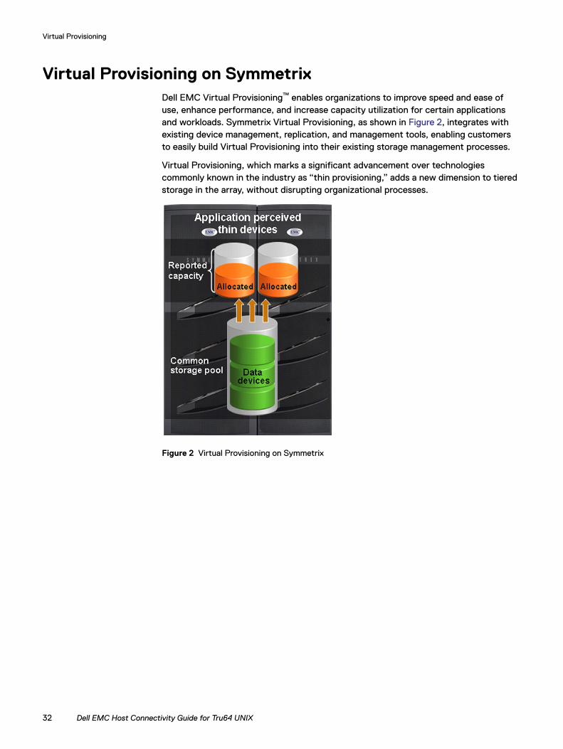
Virtual Provisioning on SymmetrixDell EMC Virtual Provisioning™ enables organizations to improve speed and ease of use, enhance performance, and increase capacity utilization for certain applications and workloads. Symmetrix Virtual Provisioning, as shown in Figure 2, integrates with existing device management, replication, and management tools, enabling customers to easily build Virtual Provisioning into their existing storage management processes.
Virtual Provisioning, which marks a significant advancement over technologies commonly known in the industry as “thin provisioning,” adds a new dimension to tiered storage in the array, without disrupting organizational processes.
Figure 2 Virtual Provisioning on Symmetrix
32 Dell EMC Host Connectivity Guide for Tru64 UNIX
Virtual Provisioning
Terminology
This section provides common terminology and definitions for Symmetrix and thin provisioning.
Symmetrix Basic Symmetrix terms include:
Thin provisioning Basic thin provisioning terms include:
Device A logical unit of storage defined within an array.
Device capacity The storage capacity of a device.
Device extent Specifies a quantum of logically contiguous blocks of storage.
Host accessible device A device that can be made available for host use.
Internal device A device used for a Symmetrix internal function that cannot be made accessible to a host.
Storage pool A collection of internal devices for some specific purpose.
Thin device A host accessible device that has no storage directly associated with it.
Data device An internal device that provides storage capacity to be used by thin devices.
Thin pool A collection of data devices that provide storage capacity for thin devices.
Thin pool capacity The sum of the capacities of the member data devices.
Thin pool allocated capacity
A subset of thin pool enabled capacity that has been allocated for the exclusive use of all thin devices bound to that thin pool.
Thin device user pre-allocated capacity
The initial amount of capacity that is allocated when a thin device is bound to a thin pool. This property is under user control.
Bind Refers to the act of associating one or more thin devices with a thin pool.
Virtual Provisioning on Symmetrix 33
Virtual Provisioning
Thin device
Symmetrix Virtual Provisioning introduces a new type of host-accessible device called a thin device that can be used in many of the same ways that regular host-accessible Symmetrix devices have traditionally been used. Unlike regular Symmetrix devices, thin devices do not need to have physical storage completely allocated at the time the devices are created and presented to a host. The physical storage that is used to supply disk space for a thin device comes from a shared thin storage pool that has been associated with the thin device.
A thin storage pool is comprised of a new type of internal Symmetrix device called a data device that is dedicated to the purpose of providing the actual physical storage used by thin devices. When they are first created, thin devices are not associated with any particular thin pool. An operation referred to as binding must be performed to associate a thin device with a thin pool.
When a write is performed to a portion of the thin device, the Symmetrix allocates a minimum allotment of physical storage from the pool and maps that storage to a region of the thin device, including the area targeted by the write. The storage allocation operations are performed in small units of storage called data device extents. A round-robin mechanism is used to balance the allocation of data device extents across all of the data devices in the pool that have remaining un-used capacity.
When a read is performed on a thin device, the data being read is retrieved from the appropriate data device in the storage pool to which the thin device is bound. Reads directed to an area of a thin device that has not been mapped does not trigger allocation operations. The result of reading an unmapped block is that a block in which each byte is equal to zero will be returned. When more storage is required to service existing or future thin devices, data devices can be added to existing thin storage pools. New thin devices can also be created and associated with existing thin pools.
Pre-provisioning An approach sometimes used to reduce the operational impact of provisioning storage. The approach consists of satisfying provisioning operations with larger devices that needed initially, so that the future cycles of the storage provisioning process can be deferred or avoided.
Over-subscribed thin pool A thin pool whose thin pool capacity is less than the sum of the reported sizes of the thin devices using the pool.
Thin device extent The minimum quantum of storage that must be mapped at a time to a thin device.
Data device extent The minimum quantum of storage that is allocated at a time when dedicating storage from a thin pool for use with a specific thin device.
34 Dell EMC Host Connectivity Guide for Tru64 UNIX
Virtual Provisioning
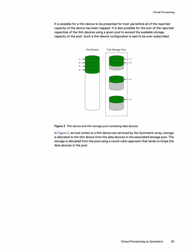
It is possible for a thin device to be presented for host use before all of the reported capacity of the device has been mapped. It is also possible for the sum of the reported capacities of the thin devices using a given pool to exceed the available storage capacity of the pool. Such a thin device configuration is said to be over-subscribed.
Figure 3 Thin device and thin storage pool containing data devices
In Figure 3, as host writes to a thin device are serviced by the Symmetrix array, storage is allocated to the thin device from the data devices in the associated storage pool. The storage is allocated from the pool using a round-robin approach that tends to stripe the data devices in the pool.
Virtual Provisioning on Symmetrix 35
Virtual Provisioning
Implementation considerationsWhen implementing Virtual Provisioning, it is important that realistic utilization objectives are set. Generally, organizations should target no higher than 60 percent to 80 percent capacity utilization per pool. A buffer should be provided for unexpected growth or a “runaway” application that consumes more physical capacity than was originally planned for. There should be sufficient free space in the storage pool equal to the capacity of the largest unallocated thin device.
Organizations also should balance growth against storage acquisition and installation timeframes. It is recommended that the storage pool be expanded before the last 20 percent of the storage pool is utilized to allow for adequate striping across the existing data devices and the newly added data devices in the storage pool.
Thin devices can be deleted once they are unbound from the thin storage pool. When thin devices are unbound, the space consumed by those thin devices on the associated data devices is reclaimed.
Note: Users should first replicate the data elsewhere to ensure it remains available for use.
Data devices can also be disabled and/or removed from a storage pool. Prior to disabling a data device, all allocated tracks must be removed (by unbinding the associated thin devices). This means that all thin devices in a pool must be unbound before any data devices can be disabled.
This section contains the following information:
◆ “Over-subscribed thin pools” on page 36
◆ “Thin-hostile environments” on page 37
◆ “Pre-provisioning with thin devices in a thin hostile environment” on page 37
◆ “Host boot/root/swap/dump devices positioned on Symmetrix VP (tdev) devices” on page 38
◆ “Cluster configurations” on page 39
Over-subscribed thin pools
It is permissible for the amount of storage mapped to a thin device to be less than the reported size of the device. It is also permissible for the sum of the reported sizes of the thin devices using a given thin pool to exceed the total capacity of the data devices comprising the thin pool. In this case the thin pool is said to be over-subscribed. Over-subscribing allows the organization to present larger-than-needed devices to hosts and applications without having to purchase enough physical disks to fully allocate all of the space represented by the thin devices.
The capacity utilization of over-subscribed pools must be monitored to determine when space must be added to the thin pool to avoid out-of-space conditions.
Not all operating systems, filesystems, logical volume managers, multipathing software, and application environments will be appropriate for use with over-subscribed thin pools. If the application, or any part of the software stack underlying the application, has a tendency to produce dense patterns of writes to all
36 Dell EMC Host Connectivity Guide for Tru64 UNIX
Virtual Provisioning
available storage, thin devices will tend to become fully allocated quickly. If thin devices belonging to an over-subscribed pool are used in this type of environment, out-of-space and undesired conditions may be encountered before an administrator can take steps to add storage capacity to the thin data pool. Such environments are called thin-hostile.
Thin-hostile environments
There are a variety of factors that can contribute to making a given application environment thin-hostile, including:
◆ One step, or a combination of steps, involved in simply preparing storage for use by the application may force all of the storage that is being presented to become fully allocated.
◆ If the storage space management policies of the application and underlying software components do not tend to reuse storage that was previously used and released, the speed in which underlying thin devices become fully allocated will increase.
◆ Whether any data copy operations (including disk balancing operations and de-fragmentation operations) are carried out as part of the administration of the environment.
◆ If there are administrative operations, such as bad block detection operations or file system check commands, that perform dense patterns of writes on all reported storage.
◆ If an over-subscribed thin device configuration is used with a thin-hostile application environment, the likely result is that the capacity of the thin pool will become exhausted before the storage administrator can add capacity unless measures are taken at the host level to restrict the amount of capacity that is actually placed in control of the application.
Pre-provisioning with thin devices in a thin hostile environment
In some cases, many of the benefits of pre-provisioning with thin devices can be exploited in a thin-hostile environment. This requires that the host administrator cooperate with the storage administrator by enforcing restrictions on how much storage is placed under the control of the thin-hostile application.
For example:
◆ The storage administrator pre-provisions larger than initially needed thin devices to the hosts, but only configures the thin pools with the storage needed initially. The various steps required to create, map, and mask the devices and make the target host operating systems recognize the devices are performed.
◆ The host administrator uses a host logical volume manager to carve out portions of the devices into logical volumes to be used by the thin-hostile applications.
Implementation considerations 37
Virtual Provisioning
◆ The host administrator may want to fully preallocate the thin devices underlying these logical volumes before handing them off to the thin-hostile application so that any storage capacity shortfall will be discovered as quickly as possible, and discovery is not made by way of a failed host write.
◆ When more storage needs to be made available to the application, the host administrator extends the logical volumes out of the thin devices that have already been presented. Many databases can absorb an additional disk partition non-disruptively, as can most file systems and logical volume managers.
◆ Again, the host administrator may want to fully allocate the thin devices underlying these volumes before assigning them to the thin-hostile application.
In this example it is still necessary for the storage administrator to closely monitor the over-subscribed pools. This procedure will not work if the host administrators do not observe restrictions on how much of the storage presented is actually assigned to the application.
Host boot/root/swap/dump devices positioned on Symmetrix VP (tdev) devices
A boot /root /swap /dump device positioned on Symmetrix Virtual Provisioning (thin) device(s) is supported with Enginuity 5773 and later. However, some specific processes involving boot /root/swap/dump devices positioned on thin devices should not have exposure to encountering the out-of-space condition. Host-based processes such as kernel rebuilds, swap, dump, save crash, and Volume Manager configuration operations can all be affected by the thin provisioning out-of-space condition. This exposure is not specific to Dell EMC's implementation of Thin Provisioning. Dell EMC strongly recommends that the customer avoid encountering the out-of-space condition involving boot / root /swap/dump devices positioned on Symmetrix VP (thin) devices using the following recommendations:
◆ We strongly recommend that Virtual Provisioning devices utilized for boot /root/dump/swap volumes must be fully allocated1 or the VP devices must not be oversubscribed2.
Should the customer use an over-subscribed thin pool, they should understand that they need to take the necessary precautions to ensure that they do not encounter the out-of-space condition.
1. A fully allocated Symmetrix VP (thin) device has 100% of the advertised space mapped to blocks in the data pool that it is bound to. This can be achieved by use of the Symmetrix VP pre-allocation mechanism or host-based utilities that will enforce pre-allocation of the space (such as, host device format.)
2. An over-subscribed Symmetrix VP (thin) device is a thin device, bound to a data pool, that does not have sufficient capacity to allocate for the advertised capacity of all the thin devices bound to that pool.
38 Dell EMC Host Connectivity Guide for Tru64 UNIX
Virtual Provisioning
◆ We do not recommend implementing space reclamation, available with Enginuity 5874 and later, with pre-allocated or over-subscribed Symmetrix VP (thin) devices that are utilized for host boot/root/swap/dump volumes. Although not recommended, Space reclamation is supported on the listed types of volumes.
Should the customer use space reclamation on this thin device, they need to be aware that this freed space may ultimately be claimed by other thin devices in the same pool and may not be available to that particular thin device in the future.
Cluster configurations
When using high availability in a cluster configuration, it is expected that no single point of failure exists within the cluster configuration and that one single point of failure will not result in data unavailability, data loss, or any significant application becoming unavailable within the cluster. Virtual provisioning devices (thin devices) are supported with cluster configurations; however, over-subscription of virtual devices may constitute a single point of failure if an out-of-space condition should be encountered. To avoid potential single points of failure, appropriate steps should be taken to avoid under-provisioned virtual devices implemented within high availability cluster configurations.
Implementation considerations 39
Virtual Provisioning
Symmetrix Virtual Provisioning in a Tru64 UNIX environmentSymmetrix Virtual Provisioning introduces advantages to the Tru64 UNIX environment otherwise not possible:
◆ Reduction of System Administration tasks
The frequency of tasks such as extending volume groups, extending logical volumes, and expansion of file systems can be reduced significantly. System administrators can configure their environments initially for future capacity requirements without the necessity of having the physical storage needed for future growth requirements available.
◆ Reduction and simplification of storage management tasks
The frequency and complexity of making new storage capacity available to hosts is significantly reduced. Storage management operations such as device assignments, LUN masking, LUN capacity changes, device discovery operations, and storage capacity availability monitoring can be reduced or simplified. Monitoring of remaining available storage capacity is simplified and more accurate. Dell EMC tools for the monitoring of thin pool capacity utilization can accurately indicate the current amount of available capacity remaining in the thin pools.
◆ Efficient storage capacity management
Efficient utilization of storage capacity is easily achieved since actual physical storage is not allocated to a Symmetrix thin device until the thin device is written to. Only the required amount storage capacity to save the update is utilized unless the user optionally pre-allocates capacity to the thin device.
◆ Performance considerations
Data written to thin devices is striped across data devices of the related thin pool (or thin pools) the thin devices are bound to. This can alleviate back-end contentions or compliment other methods of alleviating contentions, such as host-based striping.
Tru64 UNIX Virtual Provisioning support
Dell EMC Symmetrix Virtual Provisioning is supported with Tru64 UNIX v5.1B.
Precaution considerations
Virtual Provisioning and the industry’s thin provisioning are new technologies. Relevant industry specifications have not yet been drafted. Virtual Provisioning, like thin provisioning, has the potential to introduce events into the environment which would not otherwise occur. The unavailability of relevant industry standards results in deviations with the host-based handling of these events and the possibility of undesirable implications when these events occur. However, with the proper precautions these exposures can be minimized or eliminated.
Thin pool out-of-space eventInsufficient monitoring of the thin pool can result in all of the thin pool enabled capacity to be allocated to thin devices bound to the pool. If over-subscription is implemented, the thin pool out-of-space event can result in a non-recoverable error
40 Dell EMC Host Connectivity Guide for Tru64 UNIX
Virtual Provisioning
being returned to a write request when it is sent to a thin device area that does not have capacity allocated from the thin pool. Simple precautions can avoid this from occurring, including the following:
◆ Monitoring of the consumption of the thin pool enabled capacity using Dell EMC Solutions Enabler or Dell EMC Symmetrix Management console will keep the user informed when additional data devices should be added to the thin pool to avoid the thin pool out-of-space event. Threshold-based alerts can also be configured to automatically notify of the event or to add to capacity to the thin pool.
◆ Thin device allocation limits can be set to limit the amount of capacity a thin device can withdraw from the thin pool.
◆ Predictable growth of capacity utilization results in avoiding unexpected capacity demands. Implementing Virtual Provisioning with applications which have predictable growth of capacity utilization will avoid unexpected thin pool enabled capacity depletion.
◆ Avoid unnecessary block-for-block copy of a device to a thin device. Block-for-block copy of a device to a thin device results in the entire capacity of the source volume to be written to the thin device, regardless of how much user data the source volume contains. This can result in unnecessary allocation of space to the thin device.
◆ Plan for thin pool enabled capacity utilization not to exceed 60% – 80%.
File system compatibility
Choose to implement file system types which are Virtual Provisioning compatible:
◆ LSM, ADVFS, only 1% or less of thin device space is allocated at file system creation.
◆ Avoid defragmenting file systems positioned on thin devices since this can result in unnecessary capacity allocation from the thin pool.
◆ Avoid implementing Virtual Provisioning in Virtual Provisioning hostile environments.
Possible implications of the thin pool out-of-space eventThe following are possible implications of thin pool out-of-space event:
Tru64 UNIX v5.1B — Thin pool out-of-space and write request to an area of a thin device which has not had capacity allocated from the thin pool.
◆ Write request to a raw device (no fs) is not retried.
◆ LSM, ADVFS, write request not retried when system is full.
Unbound thin devices
Host-visible thin devices which are not bound to a thin pool have the same behavior as any other Symmetrix device inclusive of standard and bound thin devices, except for the handling of write requests. A process attempting to write to an unbound thin device will receive an error. An unbound thin device will appear to system administration utilities and a Volume Manager as an eligible device to be utilized or configured since
Symmetrix Virtual Provisioning in a Tru64 UNIX environment 41
Virtual Provisioning
all device discovery operations, device OPENs, and READ requests will successfully complete. However, when the system administration process attempts to write to the unbound thin device, an error will be returned.
Avoid attempting to utilize a thin device before it is bound to a thin pool.
Possible implications of write request received by an unbound thin deviceTru64 UNIX v5.1B — With visible unbound TDEVs, write request to unbound thin device results in write error which is not retried.
42 Dell EMC Host Connectivity Guide for Tru64 UNIX
CHAPTER 3Invisible Body Tag
This chapter provides information specific to AlphaServers running Tru64 UNIX and connecting to Symmetrix systems over Fibre Channel.
◆ Tru64 UNIX/Symmetrix Fibre Channel environment ................. 44◆ Host configuration with Compaq HBAs........................................ 47◆ Addressing Symmetrix devices ....................................................... 52
Tru64 UNIX and Symmetrix over Fibre Channel
Tru64 UNIX and Symmetrix over Fibre Channel 43
Tru64 UNIX and Symmetrix over Fibre Channel
Tru64 UNIX/Symmetrix Fibre Channel environmentThis section contains the following information:
◆ “Hardware connectivity,” next
◆ “Boot device support” on page 44
◆ “Logical devices” on page 44
◆ “Symmetrix configuration” on page 45
◆ “Port sharing” on page 46
Hardware connectivity
Refer to the Dell EMC Simple Support Matrix or contact your Dell EMC representative for the latest information on qualified hosts, host bus adapters, and connectivity equipment.
Boot device support
HP/Compaq hosts with Tru64 UNIX and TruCluster V5.x have been qualified for booting from Symmetrix devices interfaced through Fibre Channel as described in “Configuring boot support” on page 47.
Logical devices
LUNs are supported as follows:
1. Each Symmetrix Fibre Channel director port is a single Fibre Channel target.
OS version Max LUNs per target 1
Tru64 V4.0F/G 8 (Valid LUN addresses 000-007)
Tru64 V5.x 255 (Valid LUN addresses 000-0FE)
44 Dell EMC Host Connectivity Guide for Tru64 UNIX
Tru64 UNIX and Symmetrix over Fibre Channel
Symmetrix configuration
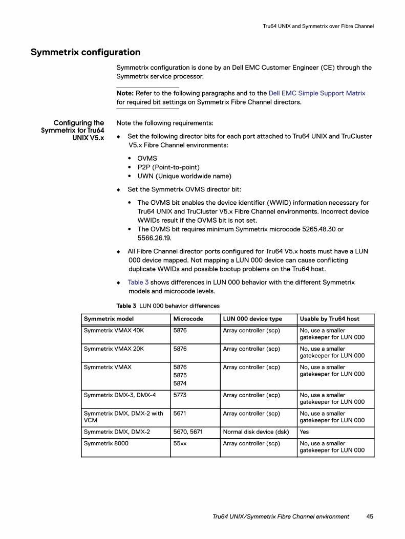
Symmetrix configuration is done by an Dell EMC Customer Engineer (CE) through the Symmetrix service processor.
Note: Refer to the following paragraphs and to the Dell EMC Simple Support Matrix for required bit settings on Symmetrix Fibre Channel directors.
Configuring theSymmetrix for Tru64
UNIX V5.x
Note the following requirements:
◆ Set the following director bits for each port attached to Tru64 UNIX and TruCluster V5.x Fibre Channel environments:
• OVMS• P2P (Point-to-point)• UWN (Unique worldwide name)
◆ Set the Symmetrix OVMS director bit:
• The OVMS bit enables the device identifier (WWID) information necessary for Tru64 UNIX and TruCluster V5.x Fibre Channel environments. Incorrect device WWIDs result if the OVMS bit is not set.
• The OVMS bit requires minimum Symmetrix microcode 5265.48.30 or 5566.26.19.
◆ All Fibre Channel director ports configured for Tru64 V5.x hosts must have a LUN 000 device mapped. Not mapping a LUN 000 device can cause conflicting duplicate WWIDs and possible bootup problems on the Tru64 host.
◆ Table 3 shows differences in LUN 000 behavior with the different Symmetrix models and microcode levels.
Table 3 LUN 000 behavior differences
Symmetrix model Microcode LUN 000 device type Usable by Tru64 host
Symmetrix VMAX 40K 5876 Array controller (scp) No, use a smaller gatekeeper for LUN 000
Symmetrix VMAX 20K 5876 Array controller (scp) No, use a smaller gatekeeper for LUN 000
Symmetrix VMAX 587658755874
Array controller (scp) No, use a smaller gatekeeper for LUN 000
Symmetrix DMX-3, DMX-4 5773 Array controller (scp) No, use a smaller gatekeeper for LUN 000
Symmetrix DMX, DMX-2 with VCM
5671 Array controller (scp) No, use a smaller gatekeeper for LUN 000
Symmetrix DMX, DMX-2 5670, 5671 Normal disk device (dsk) Yes
Symmetrix 8000 55xx Array controller (scp) No, use a smaller gatekeeper for LUN 000
Tru64 UNIX/Symmetrix Fibre Channel environment 45
Tru64 UNIX and Symmetrix over Fibre Channel
VCMDB and devicemasking guidelines
Note these requirements and recommendations:
◆ Configure and administer Symmetrix device masking from either the Tru64 UNIX host with Dell EMC Solutions Enabler Symmetrix Device Masking CLI V5.x.x or from a separate Dell EMC Ionix™ ControlCenter® host with Dell EMC SAN Manager™.
◆ On Symmetrix 8000 series systems, do not map the VCMDB as LUN 000. A VCMDB device mapped as LUN 000 cannot be updated because LUN 000 is not a normal device when the OVMS director bit is set.
◆ Enable access to LUN 000 devices. Conflicting duplicate device WWIDs can result if the LUN 000 device is masked from the Tru64 host bus adapters.
◆ TruCluster V5 hosts with persistent reservations enabled will attempt to establish reservation locks on all visible devices. A VCMDB device that has been reserved by TruCluster can be managed only from the TruCluster host.
If device masking will be managed from non-cluster hosts, do not configure the VCMDB device as visible to TruCluster hosts. You can enable a restricted access setting on the Symmetrix system to mask the VCMDB device from TruCluster hosts.
◆ Change the device label of the VCMDB device from SYM to VCM, especially if the VCMDB device is logical device 000. For example, change the label of the VCMDB device 000 from SYM000 to VCM000.
Port sharing
Tru64 UNIX V5.x hosts require special director bit settings different from Tru64 UNIX V4.0x hosts. If a Symmetrix Fibre Channel director port will be shared by Tru64 UNIX hosts, the configuration options are as follows:
◆ Set the OVMS director bit on the port as required for Tru64 UNIX V5.x hosts. If the port is on a Symmetrix 8000 system, LUN 000 will not be usable. A Tru64 UNIX V4.0x host can normally support up to 8 devices per port, but only 7 devices (LUN addresses 001– 007) will be usable by the Tru64 UNIX V4.0 host when the OVMS director bit is set. On Symmetrix DMX systems, the maximum 8 devices (LUN addresses 000 – 007) will be usable by Tru64 UNIX V4.0x hosts even when the OVMS director bit is set.
◆ Use the features in Solutions Enabler Symmetrix Device Masking CLI Version 5.1 or later to set different director bit settings for each host connected to a shared director port. The heterogeneous host configuration feature can be used to set individualized director bit settings for Tru64 UNIX V4.0 and Tru64 UNIX V5.x HBAs on the same director port. Since Tru64 UNIX hosts only configure a specific range of supported LUN addresses, the LUN base and offset adjustment feature can be used to maximize the number of LUNs available to Tru64 UNIX hosts on a shared director port.
46 Dell EMC Host Connectivity Guide for Tru64 UNIX
Tru64 UNIX and Symmetrix over Fibre Channel
Host configuration with Compaq HBAsThis section describes the tasks required to install one or more Compaq host bus adapters into the AlphaServer host and configure the host for connection to a Symmetrix system over Fibre Channel.
Planning zoning and connections
Before setting up the hardware in a fabric switch configuration with the Symmetrix, you should plan an effective zone map. Check the switch manufacturer’s user documentation for help on defining zones.
The Fibre Channel fabric must be zoned so that the Tru64 V5.x host discovers only Symmetrix Fibre Channel director ports that have been properly configured. Otherwise, misconfigured device WWIDs and associated problems may result.
Installing the HBA
Follow the instructions included with your adapter. The adapter installs into a single PCI bus slot.
If necessary, load the required HBA firmware level specified in the Dell EMC Simple Support Matrix.
Verify that the AlphaServer SRM console firmware is V5.6 or higher. At the AlphaServer console prompt, type show version and press Enter.
Note: Dell EMC recommends using the latest available console firmware version.
Console firmware updates are available on the OS Release Kit CD.
Check that the adapters are set up properly for fabric topology by using the WWIDMGR utility (wwidmgr -show adapter). Format the NVRAM (wwidmgr -set adapter -item 9999 -topo fabric) for fabric support if necessary.
Configuring boot support
Compaq hosts with Tru64 UNIX and TruCluster V5.x have been qualified for booting from Symmetrix devices interfaced through Fibre Channel. Ensure that the necessary Symmetrix director flags (OVMS, P2P, UWN) is enabled. The AlphaServer SRM console firmware should be V5.7 or higher.
Note: Dell EMC recommends using the latest available console firmware version.
To configure boot support, complete the following steps.
1. To set up the boot device, first identify the Unique Device Identifier (UDID) of the Symmetrix logical volume that will be used for boot support.
a. Run the WWIDMGR utility (wwidmgr -show wwid | more) from the AlphaServer console prompt to display the Fibre Channel devices on the system.
Host configuration with Compaq HBAs 47
Tru64 UNIX and Symmetrix over Fibre Channel
b. All devices in the WWIDMGR output have UDID and WWID values. To identify the UDID value of a specific Symmetrix logical volume, look for the WWIDMGR entry containing the expected WWID for the Symmetrix device. Symmetrix Fibre Channel device WWIDs should have the format:
6006-0480-ssss-ssss-ssss-dddd-dddd-dddd
where ssss-ssss-ssss is the Symmetrix serial number, and dddd-dddd-dddd is the Symmetrix device label (ASCII characters in hex).
The following WWID example is Symmetrix logical device 10D (5359-4d31-3044 is label SYM10D) on Symmetrix system 000184600025:
WWID:01000010:6006-0480-0001-8460-0025-5359-4d31-3044
2. Set the boot device:wwidmgr -quickset -udid <symm UDID value>
3. Reinitialize the AlphaServer console:init
4. Check that the boot device has been set:show bootdef_dev
If the variable was not set, look for the appropriate device in the show dev output and set it manually. (The Fibre Channel device has the format dg[N][UDID value].)
Example:
set bootdef_dev dga32.1001.0.3.1
Rebuilding the Tru64 UNIX kernel
If the Compaq Fibre Channel HBA is newly added to the system, the Tru64 UNIX kernel must be rebuilt to identify and support the new adapter.
To rebuild the kernel:
1. At the SRM console prompt, type boot -fi genvmunix and press Enter.
2. After the host boots, type doconfig and press Enter.
3. When prompted Do you want to edit the config file?, type N and press Enter.
4. After the kernel is built, type cp /sys/<systemname>/vmunix/ and press Enter.
5. Reboot the host.
Upgrading the Tru64 UNIX Fibre Channel driver
When new revisions of the Tru64 Fibre Channel driver are available, they are released as part of Tru64 UNIX Aggregate Patch Kits. To upgrade the driver to the latest revision available, download and install the latest OS Patch Kit from HP Tru64 UNIX Operating System and TruCluster Patch Kit Documentation.
48 Dell EMC Host Connectivity Guide for Tru64 UNIX
Tru64 UNIX and Symmetrix over Fibre Channel
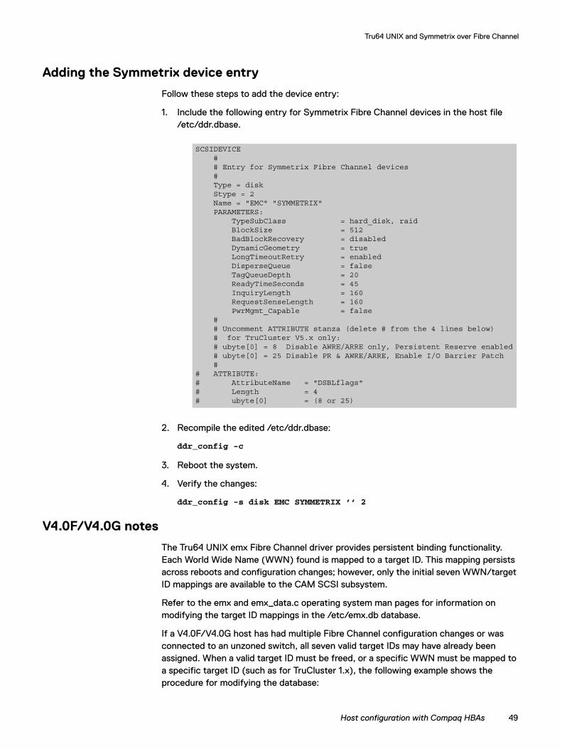
Adding the Symmetrix device entry
Follow these steps to add the device entry:
1. Include the following entry for Symmetrix Fibre Channel devices in the host file /etc/ddr.dbase.
2. Recompile the edited /etc/ddr.dbase:
ddr_config -c
3. Reboot the system.
4. Verify the changes:
ddr_config -s disk EMC SYMMETRIX ’’ 2
V4.0F/V4.0G notes
The Tru64 UNIX emx Fibre Channel driver provides persistent binding functionality. Each World Wide Name (WWN) found is mapped to a target ID. This mapping persists across reboots and configuration changes; however, only the initial seven WWN/target ID mappings are available to the CAM SCSI subsystem.
Refer to the emx and emx_data.c operating system man pages for information on modifying the target ID mappings in the /etc/emx.db database.
If a V4.0F/V4.0G host has had multiple Fibre Channel configuration changes or was connected to an unzoned switch, all seven valid target IDs may have already been assigned. When a valid target ID must be freed, or a specific WWN must be mapped to a specific target ID (such as for TruCluster 1.x), the following example shows the procedure for modifying the database:
SCSIDEVICE # # Entry for Symmetrix Fibre Channel devices # Type = disk Stype = 2 Name = "EMC" "SYMMETRIX" PARAMETERS: TypeSubClass = hard_disk, raid BlockSize = 512 BadBlockRecovery = disabled DynamicGeometry = true LongTimeoutRetry = enabled DisperseQueue = false TagQueueDepth = 20 ReadyTimeSeconds = 45 InquiryLength = 160 RequestSenseLength = 160 PwrMgmt_Capable = false # # Uncomment ATTRIBUTE stanza (delete # from the 4 lines below) # for TruCluster V5.x only: # ubyte[0] = 8 Disable AWRE/ARRE only, Persistent Reserve enabled # ubyte[0] = 25 Disable PR & AWRE/ARRE, Enable I/O Barrier Patch # # ATTRIBUTE:# AttributeName = "DSBLflags"# Length = 4# ubyte[0] = (8 or 25)
Host configuration with Compaq HBAs 49
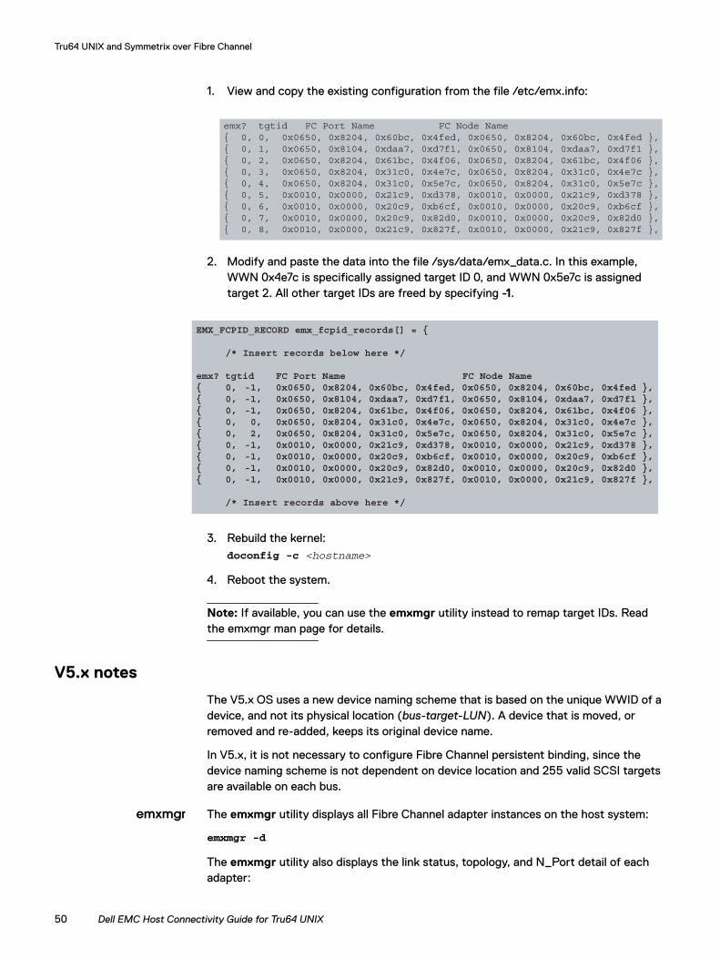
Tru64 UNIX and Symmetrix over Fibre Channel
1. View and copy the existing configuration from the file /etc/emx.info:
2. Modify and paste the data into the file /sys/data/emx_data.c. In this example, WWN 0x4e7c is specifically assigned target ID 0, and WWN 0x5e7c is assigned target 2. All other target IDs are freed by specifying -1.
3. Rebuild the kernel:doconfig -c <hostname>
4. Reboot the system.
Note: If available, you can use the emxmgr utility instead to remap target IDs. Read the emxmgr man page for details.
V5.x notes
The V5.x OS uses a new device naming scheme that is based on the unique WWID of a device, and not its physical location (bus-target-LUN). A device that is moved, or removed and re-added, keeps its original device name.
In V5.x, it is not necessary to configure Fibre Channel persistent binding, since the device naming scheme is not dependent on device location and 255 valid SCSI targets are available on each bus.
emxmgr The emxmgr utility displays all Fibre Channel adapter instances on the host system:
emxmgr -d
The emxmgr utility also displays the link status, topology, and N_Port detail of each adapter:
emx? tgtid FC Port Name FC Node Name{ 0, 0, 0x0650, 0x8204, 0x60bc, 0x4fed, 0x0650, 0x8204, 0x60bc, 0x4fed },{ 0, 1, 0x0650, 0x8104, 0xdaa7, 0xd7f1, 0x0650, 0x8104, 0xdaa7, 0xd7f1 },{ 0, 2, 0x0650, 0x8204, 0x61bc, 0x4f06, 0x0650, 0x8204, 0x61bc, 0x4f06 },{ 0, 3, 0x0650, 0x8204, 0x31c0, 0x4e7c, 0x0650, 0x8204, 0x31c0, 0x4e7c },{ 0, 4, 0x0650, 0x8204, 0x31c0, 0x5e7c, 0x0650, 0x8204, 0x31c0, 0x5e7c },{ 0, 5, 0x0010, 0x0000, 0x21c9, 0xd378, 0x0010, 0x0000, 0x21c9, 0xd378 },{ 0, 6, 0x0010, 0x0000, 0x20c9, 0xb6cf, 0x0010, 0x0000, 0x20c9, 0xb6cf },{ 0, 7, 0x0010, 0x0000, 0x20c9, 0x82d0, 0x0010, 0x0000, 0x20c9, 0x82d0 },{ 0, 8, 0x0010, 0x0000, 0x21c9, 0x827f, 0x0010, 0x0000, 0x21c9, 0x827f },
EMX_FCPID_RECORD emx_fcpid_records[] = { /* Insert records below here */
emx? tgtid FC Port Name FC Node Name{ 0, -1, 0x0650, 0x8204, 0x60bc, 0x4fed, 0x0650, 0x8204, 0x60bc, 0x4fed },{ 0, -1, 0x0650, 0x8104, 0xdaa7, 0xd7f1, 0x0650, 0x8104, 0xdaa7, 0xd7f1 },{ 0, -1, 0x0650, 0x8204, 0x61bc, 0x4f06, 0x0650, 0x8204, 0x61bc, 0x4f06 },{ 0, 0, 0x0650, 0x8204, 0x31c0, 0x4e7c, 0x0650, 0x8204, 0x31c0, 0x4e7c },{ 0, 2, 0x0650, 0x8204, 0x31c0, 0x5e7c, 0x0650, 0x8204, 0x31c0, 0x5e7c },{ 0, -1, 0x0010, 0x0000, 0x21c9, 0xd378, 0x0010, 0x0000, 0x21c9, 0xd378 },{ 0, -1, 0x0010, 0x0000, 0x20c9, 0xb6cf, 0x0010, 0x0000, 0x20c9, 0xb6cf },{ 0, -1, 0x0010, 0x0000, 0x20c9, 0x82d0, 0x0010, 0x0000, 0x20c9, 0x82d0 },{ 0, -1, 0x0010, 0x0000, 0x21c9, 0x827f, 0x0010, 0x0000, 0x21c9, 0x827f }, /* Insert records above here */
50 Dell EMC Host Connectivity Guide for Tru64 UNIX
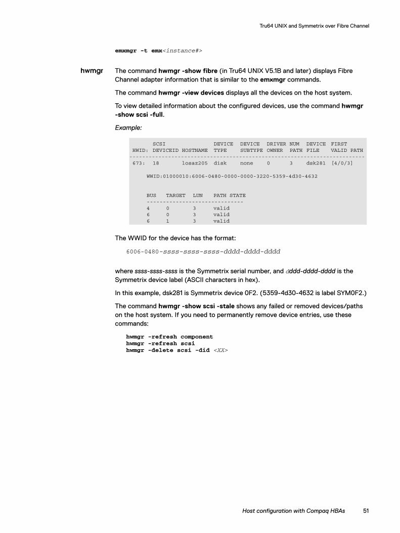
Tru64 UNIX and Symmetrix over Fibre Channel
emxmgr -t emx<instance#>
hwmgr The command hwmgr -show fibre (in Tru64 UNIX V5.1B and later) displays Fibre Channel adapter information that is similar to the emxmgr commands.
The command hwmgr -view devices displays all the devices on the host system.
To view detailed information about the configured devices, use the command hwmgr -show scsi -full.
Example:
The WWID for the device has the format:
6006-0480-ssss-ssss-ssss-dddd-dddd-dddd
where ssss-ssss-ssss is the Symmetrix serial number, and dddd-dddd-dddd is the Symmetrix device label (ASCII characters in hex).
In this example, dsk281 is Symmetrix device 0F2. (5359-4d30-4632 is label SYM0F2.)
The command hwmgr -show scsi -stale shows any failed or removed devices/paths on the host system. If you need to permanently remove device entries, use these commands:
hwmgr -refresh componenthwmgr -refresh scsihwmgr -delete scsi -did <XX>
SCSI DEVICE DEVICE DRIVER NUM DEVICE FIRST HWID: DEVICEID HOSTNAME TYPE SUBTYPE OWNER PATH FILE VALID PATH------------------------------------------------------------------------- 673: 18 losaz205 disk none 0 3 dsk281 [4/0/3]
WWID:01000010:6006-0480-0000-0000-3220-5359-4d30-4632
BUS TARGET LUN PATH STATE------------------------------4 0 3 valid 6 0 3 valid6 1 3 valid
Host configuration with Compaq HBAs 51
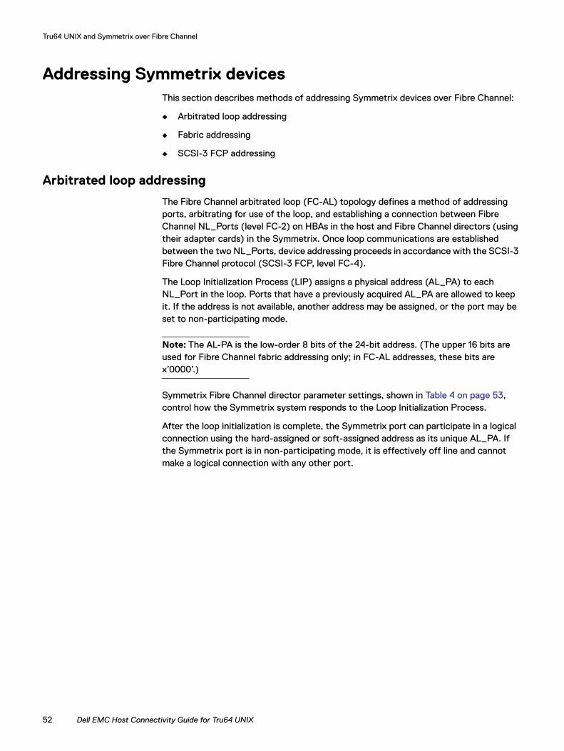
Tru64 UNIX and Symmetrix over Fibre Channel
Addressing Symmetrix devicesThis section describes methods of addressing Symmetrix devices over Fibre Channel:
◆ Arbitrated loop addressing
◆ Fabric addressing
◆ SCSI-3 FCP addressing
Arbitrated loop addressing
The Fibre Channel arbitrated loop (FC-AL) topology defines a method of addressing ports, arbitrating for use of the loop, and establishing a connection between Fibre Channel NL_Ports (level FC-2) on HBAs in the host and Fibre Channel directors (using their adapter cards) in the Symmetrix. Once loop communications are established between the two NL_Ports, device addressing proceeds in accordance with the SCSI-3 Fibre Channel protocol (SCSI-3 FCP, level FC-4).
The Loop Initialization Process (LIP) assigns a physical address (AL_PA) to each NL_Port in the loop. Ports that have a previously acquired AL_PA are allowed to keep it. If the address is not available, another address may be assigned, or the port may be set to non-participating mode.
Note: The AL-PA is the low-order 8 bits of the 24-bit address. (The upper 16 bits are used for Fibre Channel fabric addressing only; in FC-AL addresses, these bits are x’0000’.)
Symmetrix Fibre Channel director parameter settings, shown in Table 4 on page 53, control how the Symmetrix system responds to the Loop Initialization Process.
After the loop initialization is complete, the Symmetrix port can participate in a logical connection using the hard-assigned or soft-assigned address as its unique AL_PA. If the Symmetrix port is in non-participating mode, it is effectively off line and cannot make a logical connection with any other port.
52 Dell EMC Host Connectivity Guide for Tru64 UNIX
Tru64 UNIX and Symmetrix over Fibre Channel
A host initiating I/O with Symmetrix uses the AL_PA to request an open loop between itself and the Symmetrix port. Once the arbitration process has established a logical connection between the Symmetrix and the host, addressing specific logical devices is done through the SCSI-3 FCP.
Fabric addressing
Each port on a device attached to a fabric is assigned a unique 64-bit identifier called a Worldwide Port Name (WWPN). These names are factory-set on the HBAs in the hosts, and are generated on the Fibre Channel directors in the Symmetrix.
Note: For comparison to Ethernet terminology, an HBA is analogous to a NIC card, and a WWPN to a MAC address.
Note: The ANSI standard also defines a WWNN, but this name has been inconsistently defined by the industry.
When an N_Port (host server or storage device) connects to the fabric, a login process occurs between the N_Port and the F_Port on the fabric switch. During this process, the devices agree on such operating parameters as class of service, flow control rules,
Table 4 FC-AL addressing parameters
Parameter Bit Description Default
Disk Array A If enabled, the Fibre Channel Director presents the port as a disk array. Refer to Table 5 on page 55, for settings for each addressing mode.
Enabled
Volume Set V If enabled and disk array is enabled, volume set addressing mode is enabled. Refer to Table 5 on page 55, for settings for each addressing mode.
Enabled
Use Hard Addressing
H If enabled, entering an address (00 through 7D) in the Loop ID field causes the port to attempt to get the AL_PA designated by the Loop ID. If the port does not acquire the AL_PA, the Symmetrix reacts based on the state of the non-participating (NP) bit. If the NP bit is set, the port switches to non-participating mode and is not assigned an address. If non-participating mode is not selected, or if the H-bit was not set, the Symmetrix port accepts the new address that is soft-assigned by the host port.
Enabled
Hard Addressing Non-participating
NP If enabled and the H-bit is set, the director uses only the hard address. If it cannot get this address, it re-initializes and changes its state to non-participating. If the NP bit is not set, the director accepts the soft-assigned address.
Disabled
Loop ID --- Valid only if the H-bit is set, is a 1-byte address (00 through 7D).
00
Third-party Logout across the Port
TP Allows broadcast of the TPRLO extended link service through all of the FC-AL ports.
Disabled
Addressing Symmetrix devices 53
Tru64 UNIX and Symmetrix over Fibre Channel
and fabric addressing. The N_Port’s fabric address is assigned by the switch and sent to the N_Port. This value becomes the source ID (SID) on the N_Port's outbound frames and the destination ID (DID) on the N_Port's inbound frames.
The physical address is a pair of numbers that identify the switch and port, in the format s,p, where “s” is a domain ID and “p” is a value associated to a physical port in the domain. The physical address of the N_Port can change when a link is moved from one switch port to another switch port. The WWPN of the N_Port, however, does not change. A name server in the switch maintains a table of all logged-in devices, so N_Ports can automatically adjust to changes in the fabric address by keying off the WWPN.
The highest level of login that occurs is the process login. This is used to establish connectivity between the upper-level protocols on the nodes. An example is the login process that occurs at the SCSI FCP level between the HBA and the Symmetrix system.
SCSI-3 FCP addressing
The Symmetrix director extracts the SCSI Command Descriptor Blocks (CDB) from the frames received through the Fibre Channel link. Standard SCSI-3 protocol is used to determine the addressing mode and to address specific devices.
The Symmetrix supports three addressing methods based on a single-layer hierarchyas defined by the SCSI-3 controller commands (SCC):
◆ Peripheral device addressing◆ Logical unit addressing◆ Volume set addressing
All three methods use the first two bytes (0 and 1) of the eight-byte LUN addressing structure. The remaining six bytes are set to 0s.
For logical unit and volume set addressing, the Symmetrix port identifies itself as an array controller in response to a host’s Inquiry command sent to LUN 00. This identification is done by returning the byte 0x0C in the Peripheral Device Type field of the returned data for Inquiry. If the Symmetrix returns the byte 0x00 in the first byte of the returned data for Inquiry, the Symmetrix is identified as a direct access device.
Upon identifying the Symmetrix as an array controller device, the host should issue a SCSI-3 Report LUNS command (0xA0), in order to discover the LUNS.
54 Dell EMC Host Connectivity Guide for Tru64 UNIX
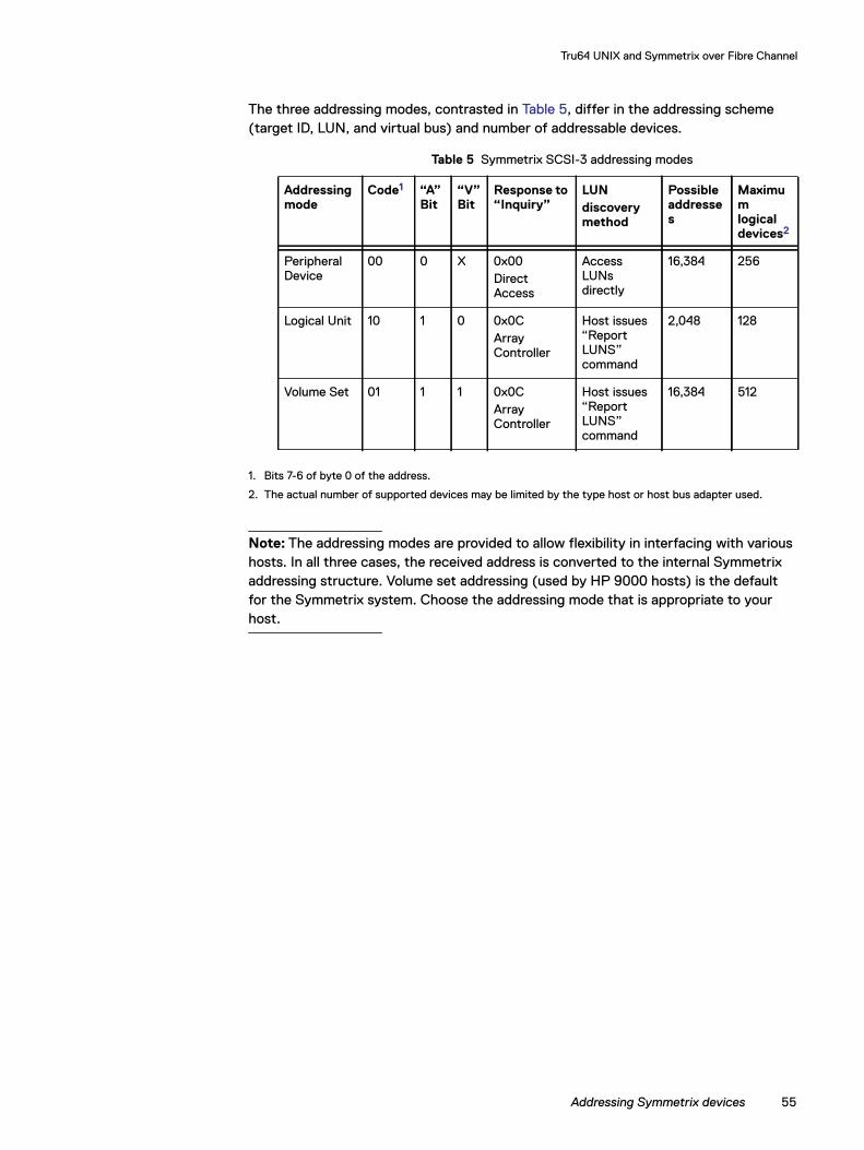
Tru64 UNIX and Symmetrix over Fibre Channel
The three addressing modes, contrasted in Table 5, differ in the addressing scheme (target ID, LUN, and virtual bus) and number of addressable devices.-
1. Bits 7-6 of byte 0 of the address.
2. The actual number of supported devices may be limited by the type host or host bus adapter used.
Note: The addressing modes are provided to allow flexibility in interfacing with various hosts. In all three cases, the received address is converted to the internal Symmetrix addressing structure. Volume set addressing (used by HP 9000 hosts) is the default for the Symmetrix system. Choose the addressing mode that is appropriate to your host.
Table 5 Symmetrix SCSI-3 addressing modes
Addressing mode
Code1 “A” Bit
“V” Bit
Response to “Inquiry”
LUNdiscovery method
Possible addresses
Maximum logical devices2
Peripheral Device
00 0 X 0x00Direct Access
Access LUNs directly
16,384 256
Logical Unit 10 1 0 0x0CArray Controller
Host issues “Report LUNS” command
2,048 128
Volume Set 01 1 1 0x0CArray Controller
Host issues “Report LUNS” command
16,384 512
Addressing Symmetrix devices 55

Tru64 UNIX and Symmetrix over Fibre Channel
56 Dell EMC Host Connectivity Guide for Tru64 UNIX
CHAPTER 4
This chapter describes how to incorporate a Symmetrix system in the Tru64 UNIX environment.
◆ Symmetrix configuration.................................................................. 58◆ Host configuration............................................................................. 59◆ Device management .......................................................................... 61
Tru64 UNIX and Symmetrix over SCSI
Tru64 UNIX and Symmetrix over SCSI 57
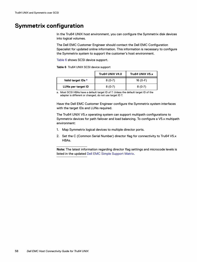
Tru64 UNIX and Symmetrix over SCSI
Symmetrix configurationIn the Tru64 UNIX host environment, you can configure the Symmetrix disk devices into logical volumes.
The Dell EMC Customer Engineer should contact the Dell EMC Configuration Specialist for updated online information. This information is necessary to configure the Symmetrix system to support the customer’s host environment.
Table 6 shows SCSI device support.
Have the Dell EMC Customer Engineer configure the Symmetrix system interfaces with the target IDs and LUNs required.
The Tru64 UNIX V5.x operating system can support multipath configurations to Symmetrix devices for path failover and load balancing. To configure a V5.x multipath environment:
1. Map Symmetrix logical devices to multiple director ports.
2. Set the C (Common Serial Number) director flag for connectivity to Tru64 V5.x HBAs.
Note: The latest information regarding director flag settings and microcode levels is listed in the updated Dell EMC Simple Support Matrix.
Table 6 Tru64 UNIX SCSI device support
a Tru64 UNIX V4.0 Tru64 UNIX V5.x
Valid target IDs a 8 (0-7) 16 (0-F)
LUNs per target ID 8 (0-7) 8 (0-7)
a. Most SCSI HBAs have a default target ID of 7. Unless the default target ID of the adapter is different or changed, do not use target ID 7.
58 Dell EMC Host Connectivity Guide for Tru64 UNIX
Tru64 UNIX and Symmetrix over SCSI
Host configuration This section describes the tasks required to install one or more Compaq host bus adapters into the AlphaServer host and configure the Tru64 UNIX environment.
Installing the HBA Follow the instructions included with the adapter. The adapter installs into a single PCI bus slot.
If necessary, load the required HBA firmware level. This information is specified in the Dell EMC Simple Support Matrix.
Also, verify that the AlphaServer SRM console firmware is current. (You can check using show version at the AlphaServer console prompt.)
Firmware Firmware updates can be downloaded from this site:
ftp://ftp.hp.com/pub/alphaserver/firmware/iso_images/
In addition, Firmware Update CDs are shipped in Tru64 UNIX Release Kits.
Host IDs To display the host IDs of the SCSI HBAs on the system, use one of the following commands at the AlphaServer console prompt:
>>> show pk*
or
>>> show isp*
The HBA host ID can be changed if an ID conflict needs to be resolved. For example, to change HBA instance c to ID 6., use:
>>> set pkc0_host_id 6.
Scanning and configuring a boot device
To perform an initial console-level scan of all devices visible to the host system before booting, use show devices | more at the AlphaServer console prompt. Verify that all configured Symmetrix SCSI devices are reported correctly in the display output.
Booting from Symmetrix devices is supported for V5.0A and V5.1 of Tru64 UNIX. Information regarding requirements and restrictions is specified in the Dell EMC Simple Support Matrix, which is available through your Dell EMC representative.
To specify a boot device, set the bootdef_dev console variable after identifying the intended boot device in the show device output. For example:
set bootdef_dev dkc301
Rebuilding the Tru64 UNIX kernel
When a new HBA is installed in the host system, the Tru64 UNIX kernel must be rebuilt to identify and support the new adapter.
To rebuild the kernel, follow these steps:
1. At the AlphaServer console prompt, type:
boot -file genvmunix -fl s
Host configuration 59
Tru64 UNIX and Symmetrix over SCSI
2. After the host boots, run bcheckrc, and then doconfig.
3. At the prompts, use the default configuration file and replace it, and then skip the config file edit.
4. When the kernel rebuild completes, copy the new kernel file to root:
cp /sys/<hostname>/vmunix /vmunix
5. Reboot the host system.
Adding the Symmetrix device entry to the ddr.dbase
To add Symmetrix devices to the Tru64 UNIX host, follow these steps:
1. Include the following entries for Symmetrix devices in the host file /etc/ddr.dbase:
SCSIDEVICEType = diskName = "EMC" "SYMMETRIX"PARAMETERS:
TypeSubClass = hard_disk, raidBlockSize = 512BadBlockRecovery = disabledDynamicGeometry = trueLongTimeoutRetry = enabledDisperseQueue = falseTagQueueDepth = 20ReadyTimeSeconds = 45InquiryLength = 160RequestSenseLength = 160PwrMgmt_Capable = false
2. Recompile the edited /etc/ddr.dbase file:
ddr_config -c
3. Reboot the host system.
4. Verify the changes:
ddr_config -s disk EMC SYMMETRIX
60 Dell EMC Host Connectivity Guide for Tru64 UNIX
Tru64 UNIX and Symmetrix over SCSI
Device managementThis section describes how to add and manage devices online.
Adding and managing devices
Table 7 describes the commands and utilities used to add and manage devices.
Example Here is an example of output showing more detail:
hwmgr -show scsi -full
Table 7 Device management commands and utilities
Version Command or utility Description
4.0x scu scan edt Rescans the devices on the host system.
scu show edt Shows the devices visible to the host.
cd /dev
./MAKEDEV <deviceName>
where <deviceName> is the filename of the device.
Creates device files for new devices, first calculate the new device name based on bus-target-lun location. For example, if a device on bus 3 target 3 lun 3 was newly added, create rzc27 device file.
scsimgr Scans and creates device files automatically. For example:scsimgr -scan_all
or scsimgr -scan_bus bus=N
5.x hwmgr -scan componenthwmgr -scan scsi
Rescans the devices on the host system.
hwmgr -view devices Views all devices visible to the host.
hwmgr -show scsi -full Shows more detailed output. Refer to “Example” on page 61.
hwmgr -show scsi -stale Shows any failed (or removed) devices/paths.
hwmgr -refresh componenthwmgr -refresh scsihwmgr -delete scsi -did <N>where <N> is the name of the SCSI device.
Permanently removes old devices from the hardware device databases.
dsfmgr • Creates device files for newly added devices. For example:dsfmgr -k
• Assigns the device name (device special file) of a failed or removed device to a new replacement device or copy:dsfmgr -m dsk1355 dsk853
• Checks device special files for inconsistencies or errors:dsfmgr -v
Device management 61
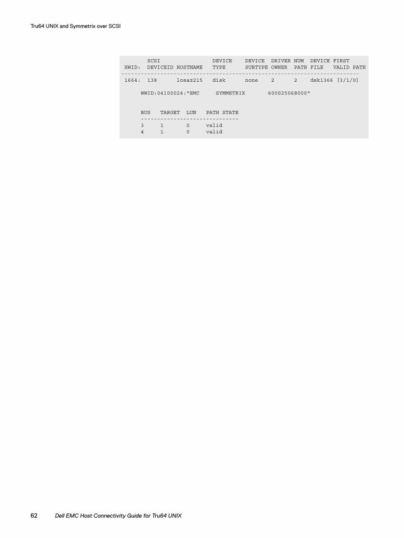
Tru64 UNIX and Symmetrix over SCSI
SCSI DEVICE DEVICE DRIVER NUM DEVICE FIRST HWID: DEVICEID HOSTNAME TYPE SUBTYPE OWNER PATH FILE VALID PATH------------------------------------------------------------------------- 1664: 138 losaz215 disk none 2 2 dsk1366 [3/1/0]
WWID:04100024:"EMC SYMMETRIX 600025068000"
BUS TARGET LUN PATH STATE ------------------------------ 3 1 0 valid 4 1 0 valid
62 Dell EMC Host Connectivity Guide for Tru64 UNIX
CHAPTER 5
This chapter discusses Symmetrix in the TruCluster environment for AlphaServer platforms running Tru64 UNIX. Fundamental concepts related to TruCluster planning, setup, and administration are provided.
◆ TruCluster V1.6 overview................................................................. 64◆ TruCluster V1.6 with Symmetrix ..................................................... 66◆ TruCluster V5.x overview................................................................. 69◆ TruCluster V5.x with Symmetrix..................................................... 72
TruCluster Servers
TruCluster Servers 63
TruCluster Servers
TruCluster V1.6 overviewTruCluster Version 1.6 is the high-availability cluster software suite for Tru64 UNIX V4.0F and V4.0G operating systems. The two types of TruCluster V1.6 configurations are Available Server and Production Server.
Available Server
An Available Server Environment (ASE) is a cluster of up to four member systems with Available Server software and shared bus connections to common external storage devices. An ASE cluster provides high availability by relocating access to the shared devices and restarting applications in the event of a failure on a member system.
Production Server
A Production Server cluster is made up of two to eight member systems connected by high-speed Memory Channel hardware interconnects. In addition to Available Server functionality, a Production Server cluster also provides Distributed Raw Disk (DRD) services and a Distributed Lock Manager (DLM) to support concurrent access to shared storage devices for applications such as Oracle Parallel Server.
TruCluster V1.6 services
Cluster services must be configured in order to make applications and/or shared storage devices highly available. The types of TruCluster services that can be configured in an ASE are:
◆ Disk services
◆ DRD services
◆ User-defined services
◆ NFS services
◆ Tape services
DRD services are only available in Production Server clusters.
A cluster service only runs on one member system at a time. Device special files, file systems, and LSM volumes can be assigned as the disk-based resources of a service. The same device (or AdvFS domain or LSM disk group) cannot be used in more than one service. The TruCluster software implements device locks on the underlying disk devices assigned to a service. The member system on which a service is started establishes the device locks (SCSI reservations) to acquire exclusive access to the shared devices in the service.
The TruCluster software uses action scripts to stop and start file systems, LSM disk groups, and applications during service relocation and fail over. File systems and LSM disk groups that have been defined in services are managed by internal action scripts. Stops and restarts of applications must be configured in user-defined action scripts. User-defined action scripts must control the processes that access a service's devices. The TruCluster software may not be able to stop a service if a mounted device is still busy.
64 Dell EMC Host Connectivity Guide for Tru64 UNIX
TruCluster Servers
asemgr
The asemgr utility is used to configure and manage the member systems and services of a TruCluster. If no command line options are specified, asemgr defaults to an interactive menu interface. The following are some commonly used asemgr command line options:
◆ To start a service:asemgr -s <service_name> <member_name>
◆ To relocate a service:asemgr -m <service_name> <member_name>
◆ To stop a service:asemgr -x <service_name>
◆ To display the status of all services and member systems:asemgr -dvh
TruCluster V1.6 daemons and error logs
Cluster daemons and drivers are essential components of TruCluster V1.6 software. A director daemon (asedirector) runs on one member in the cluster and controls the entire ASE. Agent daemons (aseagent) run on each member system to control the local cluster operations of a member. Host status monitor daemons (asehsm) run on each member system to monitor and report member status. The availability manager (AM) driver manages host pings, device pings, and device locks for each member system. The logger daemon (aselogger) tracks the events and errors reported by member systems.
Cluster events and errors are logged to the daemon.log file of the timestamp directories under /var/adm/syslog.dated. The daemon.log files are a valuable resource for troubleshooting cluster problems.
TruCluster V1.6 overview 65
TruCluster Servers
TruCluster V1.6 with Symmetrix Symmetrix supports SCSI and Fibre Channel (fabric only) connections to TruCluster V1.6 systems. Refer to the Dell EMC Simple Support Matrix for details on the AlphaServer models and Host Bus Adapters (HBAs) supported. Minimum HBA firmware revisions are also noted in the Dell EMC Simple Support Matrix.
If necessary, upgrade the HBAs in the cluster configuration with supported firmware revisions. Updating the AlphaServer systems with current SRM console firmware is recommended.
Note: Production Server requires the installation of Memory Channel hardware as a cluster interconnect.
Symmetrix connectivity
Although direct single-initiator SCSI bus connections are usually recommended for highly available Symmetrix shared device configurations, TruCluster V1.6 requires the use of multi-initiator shared buses to connect multiple member systems to shared devices. The TruCluster software monitors the status of member systems by using the HBA connections between members for a host-to-host SCSI ping.
Shared SCSI buseswith Y-cables
Multi-initiator shared SCSI buses can be configured with Y-cables, as shown in Figure 4 on page 67. Note the following guidelines for Y-cable shared buses:
◆ The shared SCSI bus must be properly terminated, with only two points of termination. The internal termination on Compaq SCSI HBAs can be disabled by removing the small yellow resistor packs on the adapter board. Symmetrix SCSI ports have small toggle switches to enable/disable termination.
◆ The total length of the shared SCSI bus from start to end (termination to termination) must be less than 25 meters.
◆ Each HBA on the shared SCSI bus must use a different SCSI ID. The HBA SCSI IDs should not conflict with the target IDs of Symmetrix devices on the shared bus. The SCSI IDs of HBAs can be checked by running show pk* or show isp* at the AlphaServer console prompt and changed with a set <pk*0_host_id> <value> command.
66 Dell EMC Host Connectivity Guide for Tru64 UNIX
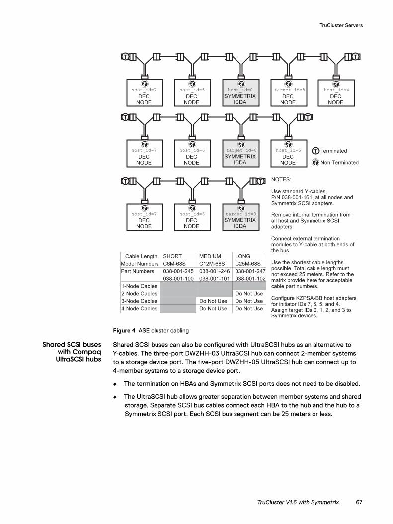
TruCluster Servers
Figure 4 ASE cluster cabling
Shared SCSI buseswith Compaq
UltraSCSI hubs
Shared SCSI buses can also be configured with UltraSCSI hubs as an alternative to Y-cables. The three-port DWZHH-03 UltraSCSI hub can connect 2-member systems to a storage device port. The five-port DWZHH-05 UltraSCSI hub can connect up to 4-member systems to a storage device port.
◆ The termination on HBAs and Symmetrix SCSI ports does not need to be disabled.
◆ The UltraSCSI hub allows greater separation between member systems and shared storage. Separate SCSI bus cables connect each HBA to the hub and the hub to a Symmetrix SCSI port. Each SCSI bus segment can be 25 meters or less.
TruCluster V1.6 with Symmetrix 67
TruCluster Servers
◆ HBAs connected to the UltraSCSI hub must use different SCSI IDs. The DWZHH-05 has a fair arbitration mode. The DWZHH-05 hub reserves SCSI ID 7 for itself and assigns SCSI IDs to specific physical ports. Refer to section 4.5.6 of the TruCluster Version 1.6 Hardware Configuration Manual before setting IDs and making port connections.
◆ The UltraSCSI hub ports require 68-pin VHDCI SCSI connectors.
Shared Fibre Channel When connecting the HBAs of member systems to shared storage devices through Fibre Channel, maintain the host-to-host SCSI ping by configuring an additional HBA-to-HBA fabric zone for each shared bus. For example:
zone_host1_symm1: host1_hba1, symm_port1zone_host2_symm1: host2_hba1, symm_port1zone_host1_host2: host1_hba1, host2_hba1
Symmetrix configuration
Refer to the Dell EMC Simple Support Matrix for correct Symmetrix director port settings. Tru64 UNIX V4.0x can support 8 target IDs (0-7) and 8 LUNs (0-7). Symmetrix Fibre Channel LUN assignments above 07 are not usable by Tru64 V4.0x systems. On Symmetrix SCSI director ports, avoid using target IDs that would conflict with the SCSI IDs of connected HBAs.
Additional documentation
TruCluster Version 1.6 release notes, hardware configuration, software installation and administration manuals are available online from the HP TrueCluster Software Products Version 1.6 Online Documentation page.
68 Dell EMC Host Connectivity Guide for Tru64 UNIX

TruCluster Servers
TruCluster V5.x overviewTruCluster Server Version 5.x is the high-availability cluster software product for Tru64 UNIX V5.x operating systems. The members of a TruCluster Server cluster operate as a single virtual system by sharing a single root file system and implementing a cluster-wide namespace for files, directories, and devices.
Connection manager
The connection manager is a kernel component that manages the formation and operation of a cluster. It monitors cluster member communication, calculates cluster quorum votes, controls membership in the cluster, and maintains cluster integrity when members join or leave.
The clu_quorum command is used to display or configure cluster quorum disks and votes. The clu_get_info command displays information about the cluster and its members.
clu_host1# clu_get_info -fullCluster information for cluster truclu
Number of members configured in this cluster = 2memberid for this member = 1Cluster incarnation = 0x90880Cluster expected votes = 3Current votes = 3Votes required for quorum = 2Quorum disk = dsk258hQuorum disk votes = 1
Information on each cluster member
Cluster memberid = 1Hostname = clu_host1Cluster interconnect IP name = clu_host1-ics0Cluster interconnect IP address = 10.0.0.1Member state = UPMember base O/S version = Compaq Tru64 UNIX V5.1A (Rev. 1885)Member cluster version = TruCluster Server V5.1A (Rev. 1312)Member running version = INSTALLEDMember name = clu_host1Member votes = 1csid = 0x10002
Cluster memberid = 2Hostname = clu_host2Cluster interconnect IP name = clu_host2-ics0Cluster interconnect IP address = 10.0.0.2Member state = UPMember base O/S version = Compaq Tru64 UNIX V5.1A (Rev. 1885)Member cluster version = TruCluster Server V5.1A (Rev. 1312)Member running version = INSTALLEDMember name = clu_host2Member votes = 1csid = 0x20001
TruCluster V5.x overview 69
TruCluster Servers
Device request dispatcher
The device request dispatcher kernel subsystem in TruCluster V5.x manages all I/O access to disk devices cluster-wide. The subsystem makes disk devices anywhere in the cluster available to all members. If the device paths of a cluster member fail, I/O transparently fails over through the cluster interconnect to another member with valid device paths.
The device request dispatcher administers barrier mechanisms to stop and block I/O from cluster members that have been removed from membership because of system failure or lost communication. The default cluster barrier establishes device locks (SCSI-3 persistent reservations) on all cluster devices.
Note: Devices that have been reserved by TruCluster cannot be accessed or written to by non-cluster hosts. If devices from a TruCluster configuration are reassigned, any previously established persistent reservations must be cleared from the devices.
TruCluster V5.x devices are either single-served or direct-access devices. Single-served devices are served by one cluster member only. Cluster members that do not serve the device can only access the device through the cluster interconnect, even if the member has direct host bus adapter connections to the device. Direct-access devices can be served by multiple cluster members. All cluster members with direct connections can access the device simultaneously. Cluster transitions and quorum can fail if single-served devices are used as TruCluster system disks.
The drdmgr command can be used to display the device request dispatcher attributes of a device. The following example is a direct-access device with two member servers:
clu_host1# drdmgr dsk752
View of Data from member clu_host1 as of 2003-02-26:17:52:45
Device Name: dsk752Device Type: Direct Access IO DiskDevice Status: OK
Number of Servers: 2Server Name: clu_host2Server State: ServerServer Name: clu_host1Server State: Server
Access Member Name: clu_host1Open Partition Mask: 0
Statistics for Client Member: clu_host1Number of Read Operations: 0Number of Write Operations: 0
Number of Bytes Read: 0Number of Bytes Written: 0
Cluster File System
The Cluster File System (CFS) software layer provides all cluster members with an identical and consistent view of mounted file systems in the cluster. Files and directories are visible and accessible from any cluster member. CFS uses a client/server model in which each file system or AdvFS domain is served to the cluster by a single member. Other cluster members access the served file system as CFS clients.
70 Dell EMC Host Connectivity Guide for Tru64 UNIX
TruCluster Servers
CFS maintains the availability of mounted file systems. If the server of a file system fails, the file system automatically fails over to another cluster member that can access the file system device(s).
Note: The sharing of common root (/), /usr, and /var file systems through CFS by cluster members simplifies cluster configuration and management. For configuration files and directories that should not or cannot be shared by all cluster members, context-dependent symbolic links (CDSLs) enable the use of member-specific files and directories. CDSLs can be created with the mkcdsl command.
Mounted file systems can be balanced among cluster members. The command cfsmgr -a server=<member_name> <file_system> relocates a file system to a specific cluster member as server. The following cfsmgr example shows the CFS attributes of all mounted file systems in a cluster:
clu_host1# cfsmgr
Domain or filesystem name = cluster_root#rootMounted On = /Server Name = clu_host1Server Status : OK
Domain or filesystem name = root2_domain#rootMounted On = /cluster/members/member2/boot_partitionServer Name = clu_host2Server Status : OK
Domain or filesystem name = cluster_var#varMounted On = /varServer Name = clu_host1Server Status : OK
Domain or filesystem name = cluster_usr#usrMounted On = /usrServer Name = clu_host1Server Status : OK
Domain or filesystem name = root1_domain#rootMounted On = /cluster/members/member1/boot_partitionServer Name = clu_host1Server Status : OK
Cluster Application Availability
The Cluster Application Availability (CAA) subsystem provides monitoring and restart mechanisms to make single-instance applications highly available. The capability is similar to that of services in TruCluster V1.6.
TruCluster V5.x overview 71
TruCluster Servers
TruCluster V5.x with SymmetrixSymmetrix model 8000 supports SCSI and Fibre Channel (fabric only) connections to TruCluster V5.x systems. Refer to the Dell EMC Simple Support Matrix for details on the AlphaServer models and HBAs supported. Minimum HBA firmware revisions are also noted in the Dell EMC Simple Support Matrix.
If necessary, upgrade the HBAs in the cluster configuration with supported firmware revisions. Updating the AlphaServer systems with current SRM console firmware is recommended.
Note: TruCluster V5.x Server requires dedicated cluster interconnect hardware. memory channel hardware is recommended for the fastest communication with the lowest latency. Starting with V5.1A, local area network (LAN) cluster interconnects are supported as an alternative to memory channel. The interconnects in a cluster must be either memory channel or LAN and cannot be mixed.
Symmetrix connectivity
TruCluster V5.x can support multipath configurations to Symmetrix Fibre Channel and SCSI devices (Figure 5 on page 73). A minimum of two device paths per cluster member is recommended for basic load balancing and path failover. Connecting shared Symmetrix devices to multiple cluster members provides continued availability in case of member failure. Additional device paths can be configured for higher availability.
72 Dell EMC Host Connectivity Guide for Tru64 UNIX
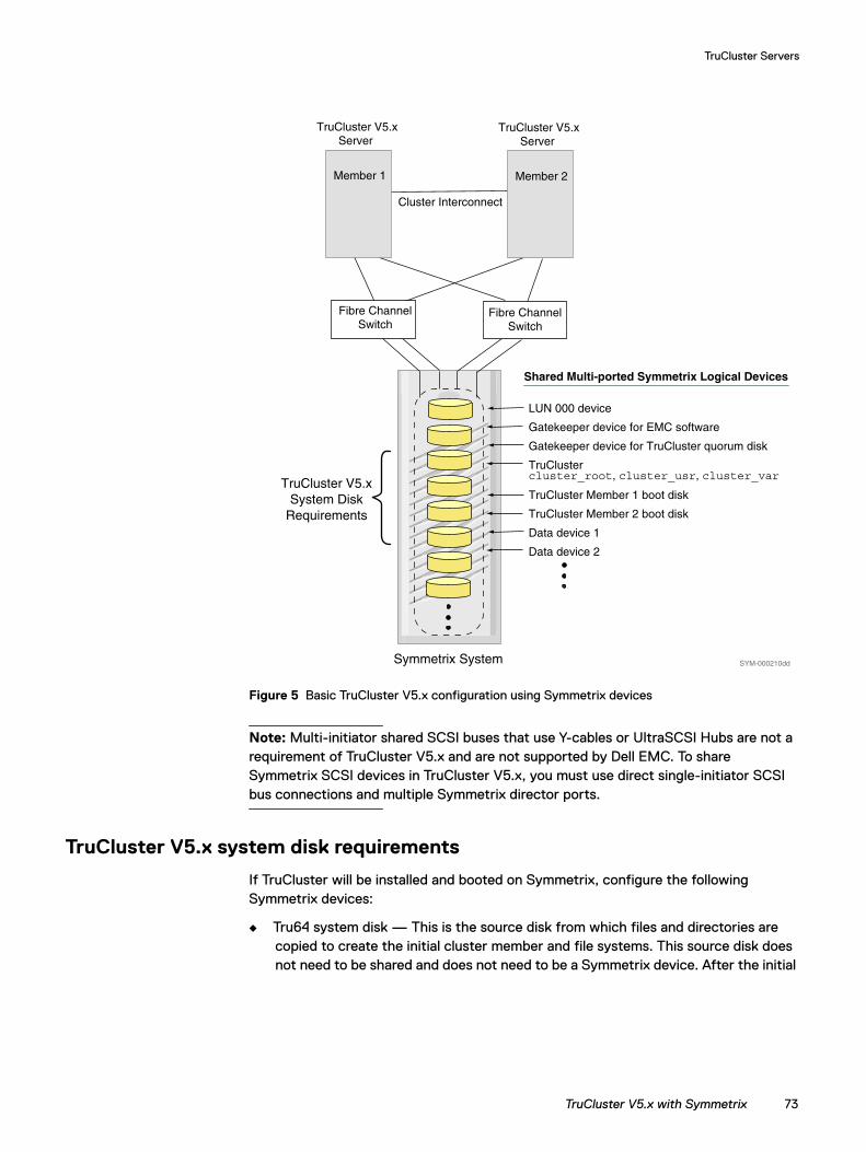
TruCluster Servers
Figure 5 Basic TruCluster V5.x configuration using Symmetrix devices
Note: Multi-initiator shared SCSI buses that use Y-cables or UltraSCSI Hubs are not a requirement of TruCluster V5.x and are not supported by Dell EMC. To share Symmetrix SCSI devices in TruCluster V5.x, you must use direct single-initiator SCSI bus connections and multiple Symmetrix director ports.
TruCluster V5.x system disk requirements
If TruCluster will be installed and booted on Symmetrix, configure the following Symmetrix devices:
◆ Tru64 system disk — This is the source disk from which files and directories are copied to create the initial cluster member and file systems. This source disk does not need to be shared and does not need to be a Symmetrix device. After the initial
Symmetrix System
TruCluster V5.x Server
Cluster Interconnect
Shared Multi-ported Symmetrix Logical Devices
TruCluster Member 1 boot disk
TruCluster Member 2 boot disk
Data device 1
Data device 2
cluster_root, cluster_usr, cluster_var
LUN 000 device
Gatekeeper device for EMC software
Gatekeeper device for TruCluster quorum disk
TruCluster
Member 1
TruCluster V5.x Server
Member 2
TruCluster V5.xSystem Disk
Requirements
SYM-000210dd
Fibre Channel Switch
Fibre Channel Switch
TruCluster V5.x with Symmetrix 73
TruCluster Servers
TruCluster member is built, the source system disk does not have any cluster-related function except as a potential emergency boot disk for resolving cluster problems.
◆ Clusterwide file system disk(s) — Three separate disk partitions are required for the cluster-wide root(/), /usr, and /var file systems. The three partitions can be from a single Symmetrix logical device. Multiple Symmetrix devices can also be used, if desired. The device(s) allocated for the cluster-wide file system should be shared and connected to all cluster members for high availability.
◆ Member boot disks — Each cluster member must have its own dedicated boot disk. A two member cluster would require two Symmetrix logical devices. The devices assigned as member boot disks should be shared and connected to all cluster members.
◆ Quorum disk — A cluster quorum disk is recommended. Only 1 MB of disk space is needed, so a Symmetrix gatekeeper device can be used as the quorum disk. The quorum disk should not be used for any other purposes. It must be shared and connected to all cluster members.
More information on TruCluster disk requirements is available in section 2.4 of the TruCluster V5.x Cluster Installation Manual.
Symmetrix configuration
Refer to the Dell EMC Simple Support Matrix for correct Symmetrix director port settings.
Tru64 UNIX V5.x can support 16 SCSI device target IDs (0-F). Do not use the same ID that is used by the HBA (usually SCSI ID 7). Eight LUNs (0-7) are supported per SCSI target ID.
Fibre Channel support is up to 255 LUNs per Fibre Channel target. Each Symmetrix Fibre director port is a single Fibre Channel target.
Assigning Symmetrix devices to multiple director ports is recommended for multipathing and clusterwide device sharing in highly available configurations.
Note: Carefully follow all documented guidelines on configuring Symmetrix Fibre Channel for Tru64/TruCluster V5.x systems, including required OVMS director bit and LUN 000 device assignments.
Persistent reservations TruCluster V5.x can be configured to use SCSI-3 persistent reservations. Minimum Symmetrix Enginuity Level 5567.53.30 (Symmetrix 8000 series) or 5669.45.24 (Symmetrix DMX series) is required for Symmetrix support of persistent reservations. To enable persistent reservation support, set the PER volume flag in IMPL Configuration Edit volumes for every Symmetrix device in the TruCluster.
Note: For more information on this topic, refer to “Persistent reservations” on page 78.
74 Dell EMC Host Connectivity Guide for Tru64 UNIX
TruCluster Servers
Direct-access device and DRD barrier configuration
Definitions for Symmetrix devices must be added to the /etc/ddr.dbase file of each cluster member in order to configure the TruCluster device request dispatcher barrier and enable Symmetrix devices as direct-access devices. The default cluster barrier mechanism uses SCSI-3 persistent reservations for device locks.
Persistent reservation support requires:
◆ Minimum Symmetrix Enginuity Level 5567.53.30 (Symmetrix 8000 series) or 5669.45.24 (Symmetrix DMX series), and PER flag enabled for each cluster-visible device
◆ Minimum TruCluster V5.1 with Patch Kit-0003 (BL17)
Note: If both requirements can be met, follow “Procedure A” on page 75 to configure the recommended cluster barrier with persistent reservation support. If one or both persistent reservation support requirements cannot be met, follow “Procedure B” on page 76 to configure an alternate cluster I/O barrier.
Procedure A Use the following to configure persistent reservation support and the recommended DRD barrier:
1. Upgrade to Symmetrix Enginuity Level 5567.53.30 (Symmetrix 8000 series) or 5669.45.24 (Symmetrix DMX series) or higher. This is the minimum microcode level required for TruCluster V5.x SCSI-3 persistent reservation support.
2. Set the PER (SCSI Persistent) flag for each Symmetrix logical device in the TruCluster V5.x configuration. The PER device flag is set using the IMPL Configuration Edit Volumes screen. Load the IMPL configuration change to enable persistent reservation support.
3. Upgrade the TruCluster V5.1 hosts with Patch Kit-0003 (BL17) or later. Earlier OS versions/levels do not provide the appropriate persistent reservation support for Symmetrix devices.
4. Add the following Dell EMC Symmetrix device entries (SCSI and Fibre Channel) to the /etc/ddr.dbase file of every cluster member, with ubyte[0]=8.
SCSIDEVICE## Entry for Symmetrix SCSI devices#Type = diskName = "EMC" "SYMMETRIX"PARAMETERS:
TypeSubClass = hard_disk, raidBlockSize = 512BadBlockRecovery = disabledDynamicGeometry = trueLongTimeoutRetry = enabledDisperseQueue = falseTagQueueDepth = 20ReadyTimeSeconds = 45InquiryLength = 160RequestSenseLength = 160PwrMgmt_Capable = false
ATTRIBUTE:# ubyte[0] = 8 Disable AWRE/ARRE only, PR enabled
TruCluster V5.x with Symmetrix 75
TruCluster Servers
# ubyte[0] = 25 Disable PR & AWRE/ARRE, Enable I/O Barrier PatchAttributeName = "DSBLflags"Length = 4ubyte[0] = 8
SCSIDEVICE## Entry for Symmetrix Fibre Channel devices#Type = diskStype = 2Name = "EMC" "SYMMETRIX"PARAMETERS:
TypeSubClass = hard_disk, raidBlockSize = 512BadBlockRecovery = disabledDynamicGeometry = trueLongTimeoutRetry = enabledDisperseQueue = falseTagQueueDepth = 20ReadyTimeSeconds = 45InquiryLength = 160RequestSenseLength = 160PwrMgmt_Capable = false
ATTRIBUTE:AttributeName = "DSBLflags"Length = 4ubyte[0] = 8
5. Run ddr_config -c on every cluster member to recompile the database.
6. Shut down all cluster members using the command:
shutdown -c now
7. Reboot each cluster member.
Procedure B Use the following to configure an alternate barrier if persistent reservations cannot be supported:
1. If running TruCluster V5.0A with Patch Kit 2 or earlier, download the necessary I/O barrier patch tar file (82108_v5_0a.tar) from Tru64 UNIX ftp site. Follow the instructions in the accompanying README file. Copy the.mod files for the patch to the appropriate directories and rebuild the cluster node kernels to complete the patch installation.
If running TruCluster V5.1 (or V5.0A with Patch Kit-003/BL17 or later), the I/O Barrier Patch functionality is already in the build. A separate patch installation is not necessary.
2. Add the following Symmetrix device entries (SCSI and Fibre Channel) to the /etc/ddr.dbase file of every cluster member, with ubyte[0]=25.
SCSIDEVICE## Entry for Symmetrix SCSI devices#Type = diskName = "EMC" "SYMMETRIX"PARAMETERS:
TypeSubClass = hard_disk, raidBlockSize = 512BadBlockRecovery = disabledDynamicGeometry = trueLongTimeoutRetry = enabled
76 Dell EMC Host Connectivity Guide for Tru64 UNIX
TruCluster Servers
DisperseQueue = falseTagQueueDepth = 20ReadyTimeSeconds = 45InquiryLength = 160RequestSenseLength = 160PwrMgmt_Capable = false
ATTRIBUTE:# ubyte[0] = 8 Disable AWRE/ARRE only, PR enabled# ubyte[0] = 25 Disable PR & AWRE/ARRE, Enable I/O Barrier Patch
AttributeName = "DSBLflags"Length = 4ubyte[0] = 25
SCSIDEVICE## Entry for Symmetrix Fibre Channel devices#Type = diskStype = 2Name = "EMC" "SYMMETRIX"PARAMETERS:
TypeSubClass = hard_disk, raidBlockSize = 512BadBlockRecovery = disabledDynamicGeometry = trueLongTimeoutRetry = enabledDisperseQueue = falseTagQueueDepth = 20ReadyTimeSeconds = 45InquiryLength = 160RequestSenseLength = 160PwrMgmt_Capable = false
ATTRIBUTE:AttributeName = "DSBLflags"Length = 4ubyte[0] = 25
3. Run ddr_config -c on every cluster member to recompile the database.
4. Shut down all cluster members using the command:
shutdown -c now
5. Reboot each cluster member.
Verifying a Symmetrixentry
Use the following commands to verify the Symmetrix device entries in the /etc/ddr.dbase file for each cluster member:
1. Check to see if the /etc/ddr.dbase has the Symmetrix device entry definitions applied successfully:
ddr_config -s disk EMC SYMMETRIX ’’ 2
Building Device Information for:Type = diskVendor ID: "EMC" Product ID: "SYMMETRIX"
Applying Modifications from Device Record for :Stype: 0x2 Vendor ID: "EMC" Product ID: "SYMMETRIX"
2. Use drdmgr dsk <N> to confirm that Symmetrix devices have Direct Access IO Disk for the device type:
Device Name: dsk100Device Type: Direct Access IO Disk
TruCluster V5.x with Symmetrix 77
TruCluster Servers
Device Status: OKNumber of Servers: 2
Server Name: clu_host2Server State: ServerServer Name: clu_host1Server State: Server
Access Member Name: clu_host1Open Partition Mask: 0x4 < c >
Statistics for Client Member: clu_host1Number of Read Operations: 372345
Number of Write Operations: 399320Number of Bytes Read: 4529668096
Number of Bytes Written: 11858483200
Persistent reservations
TruCluster V5.x will establish SCSI-3 persistent reservations on all visible disk devices in the cluster. These device reservations prevent write access by other hosts. If devices in a TruCluster configuration are moved or reassigned to a host that is not a member of the TruCluster, the cluster's persistent reservations must be cleared before the devices can be written to by the non-cluster host. The /usr/sbin/cleanPR script can be used to clear persistent reservations from devices previously reserved by TruCluster. Modify the cleanPR script to include Dell EMC devices, or contact your Dell EMC representative or customer support to obtain a special script for clearing persistent reservations from Dell EMC devices.
Due to the potential difficulties in clearing persistent reservations from devices, devices that were allocated for use in a TruCluster should remain in the cluster if possible. Dell EMC does not recommend configurations in which devices will be moved in and out of a TruCluster configuration on a regular basis. For example, if BCVs will be used in a TruCluster or established to TruCluster devices, the BCVs should remain assigned exclusively in the TruCluster or assigned exclusively to a backup/secondary host, the BCVs should not be moved back and forth between the TruCluster and a backup/secondary host. If there is an unavoidable requirement to reassign devices periodically between a TruCluster and a backup/secondary host, a recommended solution is to use another TruCluster as the backup/secondary host. TruCluster hosts can clear existing reservations and establish new reservations on previously reserved devices.
Additional documentation
TruCluster Version 5.x technical overview, release notes, hardware configuration, cluster installation, and cluster administration manuals are available online on the HP TruCluster Server Online Documentation page.
78 Dell EMC Host Connectivity Guide for Tru64 UNIX

PART 2
Part 2 includes:
◆ Chapter 6, ”Tru64 UNIX Hosts with VNX Series and CLARiiON”
VNX Series and CLARiiON Connectivity

CHAPTER 6Invisible Body Tag
This chapter provides information specific to AlphaServers running Tru64 UNIX and connecting to EMC VNX series and EMC CLARiiON storage systems.
◆ Tru64 UNIX in a VNX series and CLARiiON environment ........ 82◆ Host configuration with Compaq HBAs........................................ 84◆ Booting from the VNX series and CLARiiON storage system.... 93◆ TruCluster configurations and persistent reservations ................ 98◆ Configuring LUNs on the host ...................................................... 102
Tru64 UNIX Hosts with VNX Series and CLARiiON
Tru64 UNIX Hosts with VNX Series and CLARiiON 81
Tru64 UNIX Hosts with VNX Series and CLARiiON
Tru64 UNIX in a VNX series and CLARiiON environmentThis section lists EMC VNX™, EMC CLARiiON™ and Fibre Channel support information specific to the Tru64 UNIX environment.
Host connectivity
Refer to the Dell EMC Simple Support Matrix or contact your Dell EMC representative for the latest information on qualified hosts, HBAs, and connectivity equipment.
Boot device support
Compaq hosts running Tru64 UNIX and, optionally, TruCluster V5.x are qualified for booting from VNX series and CLARiiON systems as described in the section “Booting from the VNX series and CLARiiON storage system” on page 93.
Logical devices
VNX series and CLARiiON support for Tru64 UNIX requires Dell EMC AccessLogix™. Hosts can only be connected to one storage group per VNX series and CLARiiON system. The maximum number of LUNs per Storage Group is 256, but Tru64 UNIX V5.x only supports up to 255 LUNs per Fibre Channel target ID, so 255 is the maximum number of VNX series and CLARiiON systems that can be supported by each Tru64 UNIX host connected to an array.
The logical devices presented by VNX series and CLARiiON are the same on each storage processor (SP). A logical unit (LU) reports itself Device Ready on one SP and Device Not Ready on the other SP.
General configuration overview
Storage components
The basic components of a storage-system configuration are:
◆ One or more storage systems.
◆ One or more servers connected to the storage system(s), directly or through hubs or switches. A server can run Novell NetWare, Microsoft Windows NT, Microsoft Windows2000, or one of several UNIX operating systems, such as IBM AIXor Solaris.
◆ For EMC Unisphere™/Navisphere™ 5.x or lower, a Windows NT or Windows 2000 host (called a management station) that is running Navisphere Manager and is connected over a local area network (LAN) to storage-system servers and the storage processors (SPs) in VNX series and CLARiiON storage systems. (A management station can also be a storage-system server if it is connected to a storage system.)
82 Dell EMC Host Connectivity Guide for Tru64 UNIX
Tru64 UNIX Hosts with VNX Series and CLARiiON
◆ For Unisphere/Navisphere 6.x, a host that is running an operating system that supports the Unisphere/Navisphere Manager browser-based client and is connected over a LAN to storage-system servers and the SPs in VNX series and CLARiiON storage systems. For a current list of operating systems, refer to the Dell EMC Simple Support Matrix.
Required storage system setup
VNX series and CLARiiON configuration is done by an Dell EMC Customer Engineer (CE) through Unisphere/Navisphere Manager. The CE will configure your storage system settings for each Fibre Channel port.
The procedures in this document assume that switches and storage systems used in this configuration are already installed, and that the storage system processors are connected to the switch ports.
Tru64 UNIX in a VNX series and CLARiiON environment 83
Tru64 UNIX Hosts with VNX Series and CLARiiON
Host configuration with Compaq HBAsThis section describes the tasks required to install one or more Compaq HBAs into the AlphaServer host and configure the host for VNX series and CLARiiON storage systems.
The procedures described here assume you have already connected the SPs for the storage system to the fabric.
The configuration process consists of the following steps (described later in this section):
1. Install the HBA.
2. Create an entry for the logical units of the storage system in /etc/ddr.dbase.
3. Upgrade the Tru64 UNIX HBA driver, if necessary.
4. Rebuild the Tru64 kernel, if necessary.
5. Establish proper, single-initiator zoning.
6. Set the Unique Device Identifier (UDID) for the storage system.
7. Create initiator records with the correct properties for the storage system connection to the HBA(s).
8. Create the storage group on the storage system.
After these steps are executed, the logical units in the storage group are available for use by the Tru64 UNIX system.
Installing the HBA
Follow the instructions included with your HBA. The HBA installs into a single PCI bus slot.
If necessary, load the required HBA firmware level specified in the Dell EMC Simple Support Matrix.
Verifying consolefirmware
Verify that AlphaServer SRM console firmware V6.1 or higher is installed. At the SRM console prompt, type show version and press Enter.
Note: Dell EMC recommends using the latest available console firmware version.
Console and HBA firmware updates are available on the Operating System Release Kit CD, and also can be downloaded from the following location:
ftp://ftp.hp.com/pub/alphaserver/firmware/iso_images/
Verifying and settingHBAs
Use the WWIDMGR utility to verify that the HBAs are configured for the fabric topology. You may have to perform an init from the console prior to running WWIDMGR.
◆ To show the current state of the adapters, use this command:
wwidmgr -show adapter
84 Dell EMC Host Connectivity Guide for Tru64 UNIX
Tru64 UNIX Hosts with VNX Series and CLARiiON
◆ If the adapters are not set for fabric, set them with this command:
wwidmgr -set adapter -item 9999 -topo fabric
Note: This command sets all adapters to fabric topology.
Creating an entry in ddr.dbase
Before making a physical connection between the VNX series and CLARiiON storage system and the Tru64 UNIX system, the ddr.dbase file must be updated with a new entry describing the interaction between Tru64 UNIX and the LUNs that are about to be presented to it. If you are running in a TruCluster environment, refer to “Enabling persistent reservations” on page 98 for the correct ddr.dbase entry.
Note: Failure to perform this step first can lead to unpredictable and potentially detrimental interactions between Tru64 UNIX and the storage system.
To create an entry in ddr.dbase, complete the following steps.
1. Using any editor, insert the following text into the Disks section of the /etc/ddr.dbase file:
SCSIDEVICE## Entry for CLARiiON Storage#Type = diskStype = 2Name = "DGC"#PARAMETERS:#TypeSubClass = hard_disk, raidBlockSize = 512BadBlockRecovery = disabledDynamicGeometry = trueDisperseQueue = falseTagQueueDepth = 32PwrMgmt_Capable = falseLongTimeoutRetry = enabledReadyTimeSeconds = 90InquiryLength = 120RequestSenseLength = 120#
ATTRIBUTE:## Disable PR/AWRE/ARRE and enable I/O Barrier#AttributeName = "DSBLflags"Length = 4ubyte[0] = 25#
ATTRIBUTE:## Disable Start Unit with every VPD Inquiry#AttributeName = "VPDinfo"Length = 16ubyte[6] = 4#
Host configuration with Compaq HBAs 85
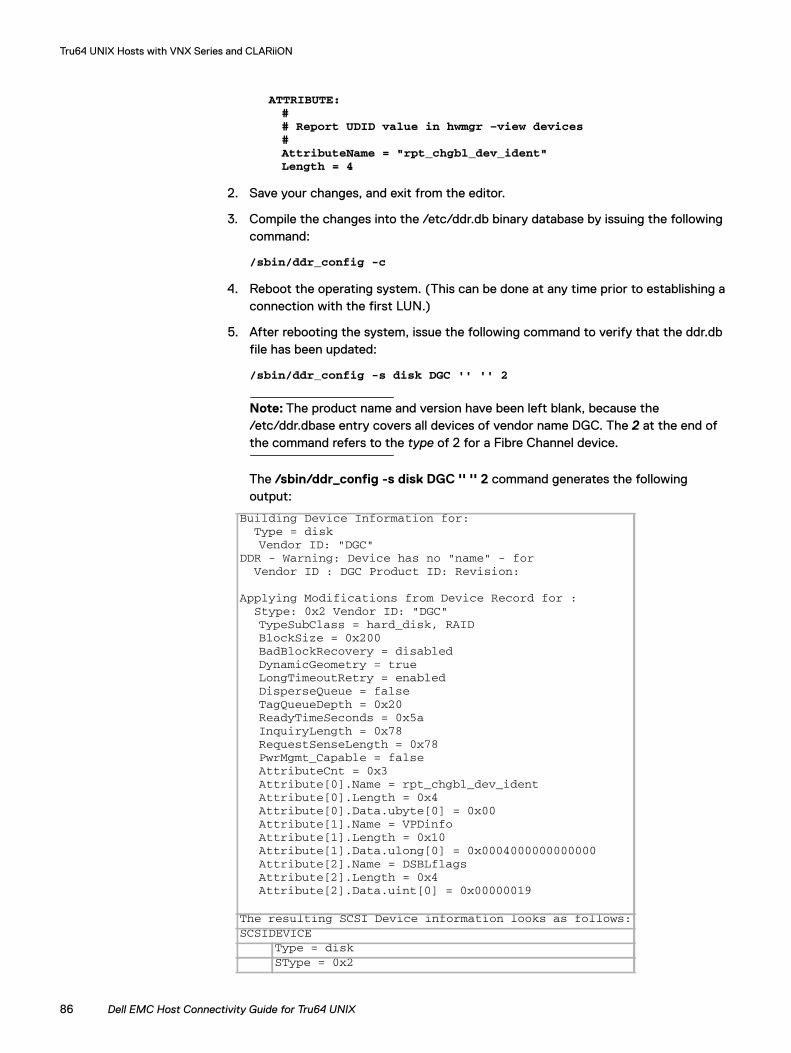
Tru64 UNIX Hosts with VNX Series and CLARiiON
ATTRIBUTE:## Report UDID value in hwmgr –view devices#AttributeName = "rpt_chgbl_dev_ident"Length = 4
2. Save your changes, and exit from the editor.
3. Compile the changes into the /etc/ddr.db binary database by issuing the following command:
/sbin/ddr_config -c
4. Reboot the operating system. (This can be done at any time prior to establishing a connection with the first LUN.)
5. After rebooting the system, issue the following command to verify that the ddr.db file has been updated:
/sbin/ddr_config -s disk DGC '' '' 2
Note: The product name and version have been left blank, because the /etc/ddr.dbase entry covers all devices of vendor name DGC. The 2 at the end of the command refers to the type of 2 for a Fibre Channel device.
The /sbin/ddr_config -s disk DGC '' '' 2 command generates the following output:
Building Device Information for:Type = diskVendor ID: "DGC"
DDR - Warning: Device has no "name" - forVendor ID : DGC Product ID: Revision:
Applying Modifications from Device Record for :Stype: 0x2 Vendor ID: "DGC"TypeSubClass = hard_disk, RAIDBlockSize = 0x200BadBlockRecovery = disabledDynamicGeometry = trueLongTimeoutRetry = enabledDisperseQueue = falseTagQueueDepth = 0x20ReadyTimeSeconds = 0x5aInquiryLength = 0x78RequestSenseLength = 0x78PwrMgmt_Capable = falseAttributeCnt = 0x3Attribute[0].Name = rpt_chgbl_dev_identAttribute[0].Length = 0x4Attribute[0].Data.ubyte[0] = 0x00Attribute[1].Name = VPDinfoAttribute[1].Length = 0x10Attribute[1].Data.ulong[0] = 0x0004000000000000Attribute[2].Name = DSBLflagsAttribute[2].Length = 0x4Attribute[2].Data.uint[0] = 0x00000019
The resulting SCSI Device information looks as follows:SCSIDEVICE
Type = diskSType = 0x2
86 Dell EMC Host Connectivity Guide for Tru64 UNIX
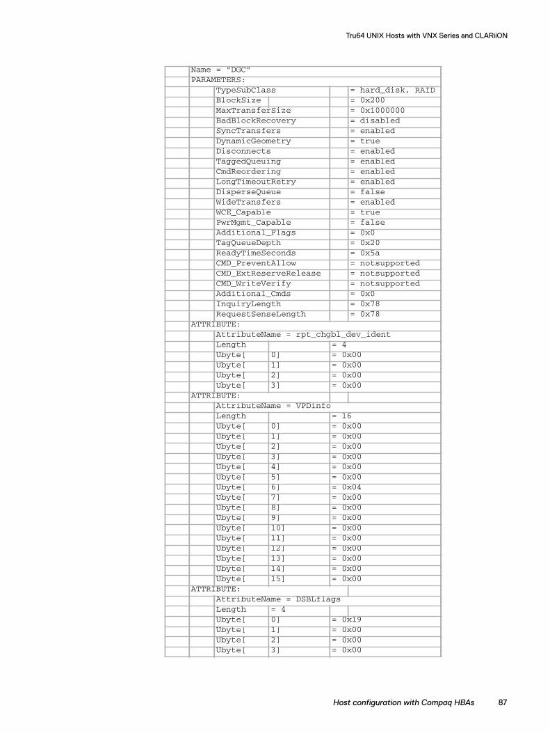
Tru64 UNIX Hosts with VNX Series and CLARiiON
Name = "DGC"PARAMETERS:
TypeSubClass = hard_disk, RAIDBlockSize = 0x200MaxTransferSize = 0x1000000BadBlockRecovery = disabledSyncTransfers = enabledDynamicGeometry = trueDisconnects = enabledTaggedQueuing = enabledCmdReordering = enabledLongTimeoutRetry = enabledDisperseQueue = falseWideTransfers = enabledWCE_Capable = truePwrMgmt_Capable = falseAdditional_Flags = 0x0TagQueueDepth = 0x20ReadyTimeSeconds = 0x5aCMD_PreventAllow = notsupportedCMD_ExtReserveRelease = notsupportedCMD_WriteVerify = notsupportedAdditional_Cmds = 0x0InquiryLength = 0x78RequestSenseLength = 0x78
ATTRIBUTE:AttributeName = rpt_chgbl_dev_identLength = 4Ubyte[ 0] = 0x00Ubyte[ 1] = 0x00Ubyte[ 2] = 0x00Ubyte[ 3] = 0x00
ATTRIBUTE:AttributeName = VPDinfoLength = 16Ubyte[ 0] = 0x00Ubyte[ 1] = 0x00Ubyte[ 2] = 0x00Ubyte[ 3] = 0x00Ubyte[ 4] = 0x00Ubyte[ 5] = 0x00Ubyte[ 6] = 0x04Ubyte[ 7] = 0x00Ubyte[ 8] = 0x00Ubyte[ 9] = 0x00Ubyte[ 10] = 0x00Ubyte[ 11] = 0x00Ubyte[ 12] = 0x00Ubyte[ 13] = 0x00Ubyte[ 14] = 0x00Ubyte[ 15] = 0x00
ATTRIBUTE:AttributeName = DSBLflagsLength = 4Ubyte[ 0] = 0x19Ubyte[ 1] = 0x00Ubyte[ 2] = 0x00Ubyte[ 3] = 0x00
Host configuration with Compaq HBAs 87
Tru64 UNIX Hosts with VNX Series and CLARiiON
Note: You can safely ignore the warning message, which indicates that the product name is blank, so that all devices with a vendor name of DGC match this entry.
To minimize the risk of typographical errors causing any problems, you should verify the entries. Pay particular attention to the sections labeled ATTRIBUTE.
Upgrading the Tru64 UNIX Fibre Channel HBA driver
New revisions of the Tru64 UNIX Fibre Channel HBA driver are released as part of the Tru64 UNIX Patch Kits. To upgrade the driver to the latest revision available, download and install the latest Aggregate Patch Kit from HP Tru64 UNIX Operating System and TruCluster Patch Kit Documentation.
Follow the instructions that are included with this kit. Part of the process is to rebuild the kernel.
What next? If Fibre Channel HBA support is not built into the kernel as part of the patch process, follow the steps under “Rebuilding the Tru64 UNIX kernel” on page 88.
Rebuilding the Tru64 UNIX kernel
When a Fibre Channel HBA is the first added to the server, the Tru64 UNIX kernel must be rebuilt to incorporate support for the adapter. Follow the following steps to rebuild the kernel:
1. At the SRM console prompt, type boot -fi genvmunix and press Enter.
2. After the system has booted, type doconfig and press Enter.
3. When prompted Do you want to edit the config file?, type N and press Enter.
4. After the kernel has been built, type cp /sys/<systemname>/vmunix / and press Enter.
systemname> is the hostname of your server.
5. Reboot the host.
Zoning HBA connections
Connect the Tru64 UNIX Fibre Channel HBA(s) into the fabric and zone the HBA(s) to your VNX series and CLARiiON SP(s). Zones should be single-initiator, so that each zone contains only one HBA. Refer to your fabric switch documentation for information to set up zones on your particular hardware.
Setting the UDID
The Base UUID field in the Storage System Properties dialog box, shown in Figure 6 on page 89, can be set to any value from 1 to 30319. The UDIDs (Unique Device Identifiers) reported by VNX series and CLARiiON LUNs are dependent on the Base UUID of the VNX series and CLARiiON storage system and the individual LUN's Host ID.
88 Dell EMC Host Connectivity Guide for Tru64 UNIX
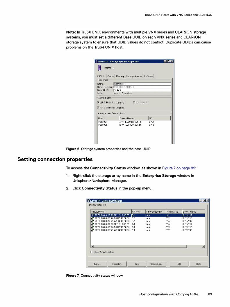
Tru64 UNIX Hosts with VNX Series and CLARiiON
Note: In Tru64 UNIX environments with multiple VNX series and CLARiiON storage systems, you must set a different Base UUID on each VNX series and CLARiiON storage system to ensure that UDID values do not conflict. Duplicate UDIDs can cause problems on the Tru64 UNIX host.
Figure 6 Storage system properties and the base UUID
Setting connection properties
To access the Connectivity Status window, as shown in Figure 7 on page 89:
1. Right-click the storage array name in the Enterprise Storage window in Unisphere/Navisphere Manager.
2. Click Connectivity Status in the pop-up menu.
Figure 7 Connectivity status window
Host configuration with Compaq HBAs 89
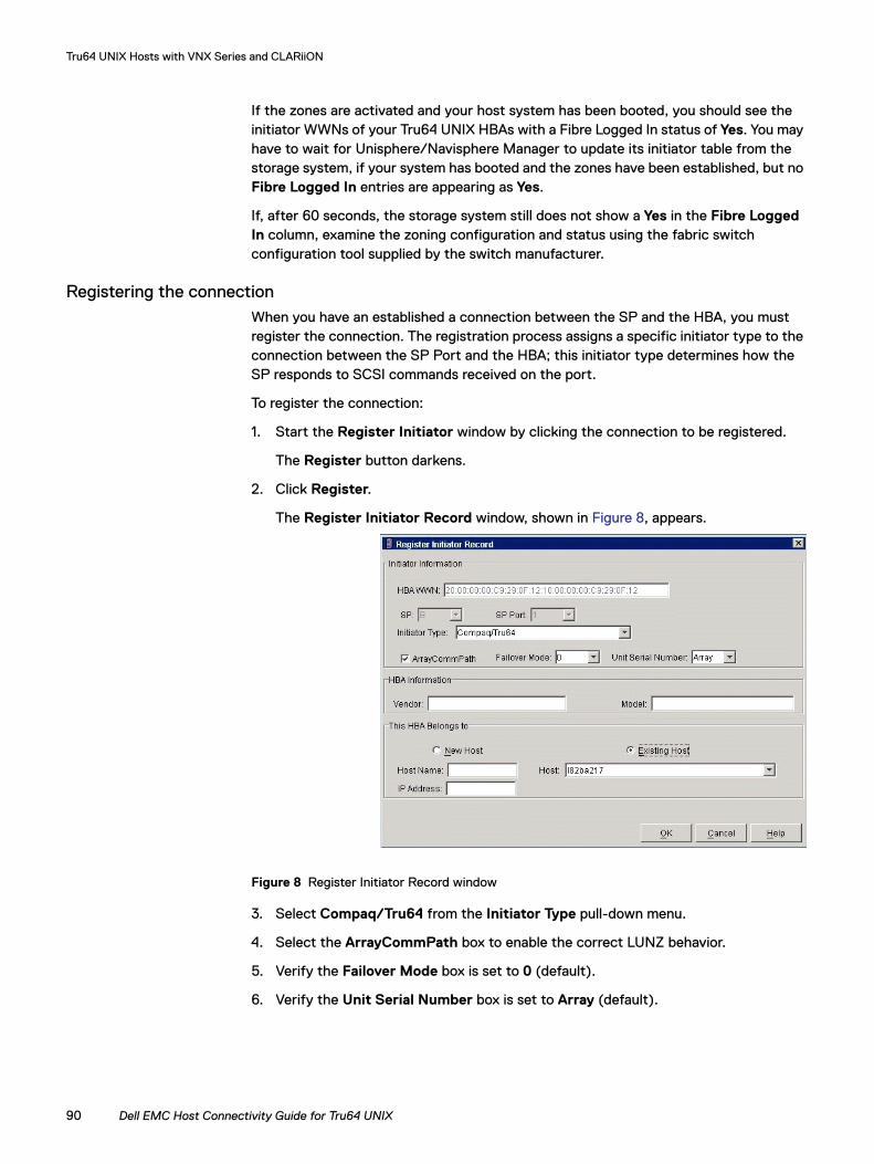
Tru64 UNIX Hosts with VNX Series and CLARiiON
If the zones are activated and your host system has been booted, you should see the initiator WWNs of your Tru64 UNIX HBAs with a Fibre Logged In status of Yes. You may have to wait for Unisphere/Navisphere Manager to update its initiator table from the storage system, if your system has booted and the zones have been established, but no Fibre Logged In entries are appearing as Yes.
If, after 60 seconds, the storage system still does not show a Yes in the Fibre Logged In column, examine the zoning configuration and status using the fabric switch configuration tool supplied by the switch manufacturer.
Registering the connectionWhen you have an established a connection between the SP and the HBA, you must register the connection. The registration process assigns a specific initiator type to the connection between the SP Port and the HBA; this initiator type determines how the SP responds to SCSI commands received on the port.
To register the connection:
1. Start the Register Initiator window by clicking the connection to be registered.
The Register button darkens.
2. Click Register.
The Register Initiator Record window, shown in Figure 8, appears.
Figure 8 Register Initiator Record window
3. Select Compaq/Tru64 from the Initiator Type pull-down menu.
4. Select the ArrayCommPath box to enable the correct LUNZ behavior.
5. Verify the Failover Mode box is set to 0 (default).
6. Verify the Unit Serial Number box is set to Array (default).
90 Dell EMC Host Connectivity Guide for Tru64 UNIX
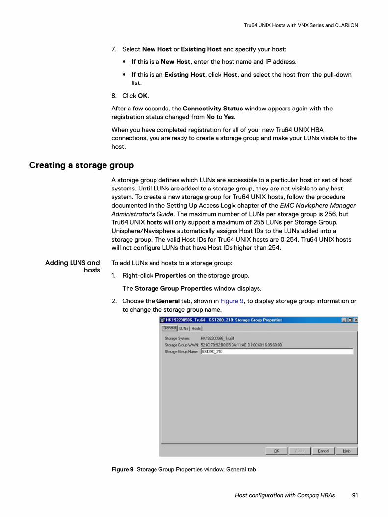
Tru64 UNIX Hosts with VNX Series and CLARiiON
7. Select New Host or Existing Host and specify your host:
• If this is a New Host, enter the host name and IP address.
• If this is an Existing Host, click Host, and select the host from the pull-down list.
8. Click OK.
After a few seconds, the Connectivity Status window appears again with the registration status changed from No to Yes.
When you have completed registration for all of your new Tru64 UNIX HBA connections, you are ready to create a storage group and make your LUNs visible to the host.
Creating a storage group
A storage group defines which LUNs are accessible to a particular host or set of host systems. Until LUNs are added to a storage group, they are not visible to any host system. To create a new storage group for Tru64 UNIX hosts, follow the procedure documented in the Setting Up Access Logix chapter of the EMC Navisphere Manager Administrator's Guide. The maximum number of LUNs per storage group is 256, but Tru64 UNIX hosts will only support a maximum of 255 LUNs per Storage Group. Unisphere/Navisphere automatically assigns Host IDs to the LUNs added into a storage group. The valid Host IDs for Tru64 UNIX hosts are 0-254. Tru64 UNIX hosts will not configure LUNs that have Host IDs higher than 254.
Adding LUNS andhosts
To add LUNs and hosts to a storage group:
1. Right-click Properties on the storage group.
The Storage Group Properties window displays.
2. Choose the General tab, shown in Figure 9, to display storage group information or to change the storage group name.
Figure 9 Storage Group Properties window, General tab
Host configuration with Compaq HBAs 91
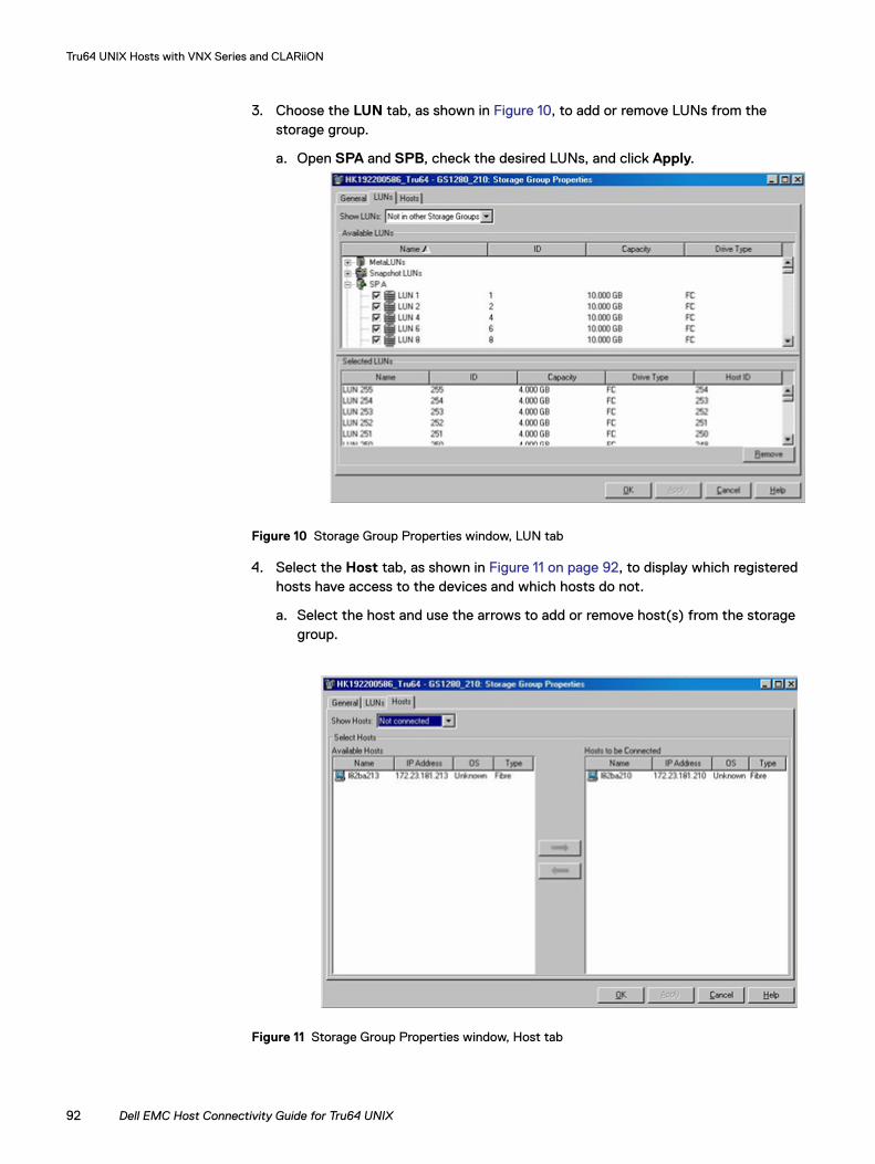
Tru64 UNIX Hosts with VNX Series and CLARiiON
3. Choose the LUN tab, as shown in Figure 10, to add or remove LUNs from the storage group.
a. Open SPA and SPB, check the desired LUNs, and click Apply.
Figure 10 Storage Group Properties window, LUN tab
4. Select the Host tab, as shown in Figure 11 on page 92, to display which registered hosts have access to the devices and which hosts do not.
a. Select the host and use the arrows to add or remove host(s) from the storage group.
Figure 11 Storage Group Properties window, Host tab
92 Dell EMC Host Connectivity Guide for Tru64 UNIX
Tru64 UNIX Hosts with VNX Series and CLARiiON
Booting from the VNX series and CLARiiON storage systemDell EMC supports booting Tru64 UNIX from a LUN on the FC4700 (Base Code release 8.45.5x minimum) or a CX-series storage system. This section describes the requisite steps that enable the host to boot from the storage system.
Several of these steps are identical to those described in “Host configuration with Compaq HBAs” on page 84; however, these steps may not be executed in the same order in both scenarios. The requirements for attaching to the VNX series and CLARiiON system in the non-booting case are different from those needed when booting from the storage system; these differing requirements mandate a change in order of certain steps. Follow the instructions appropriate for your installation.
The steps (described later in this section) are:
1. Install the HBA.
2. Set the Unique Device Identifier (UDID) for the storage system.
3. Establish a preliminary single-initiator zone to one SP only.
4. Create Initiator records with the correct properties for the storage system connection to the HBA(s).
5. Create a storage group on the array.
6. Prepare the LUN(s) for installing the operating system.
7. Use wwidmgr to identify the boot device that will contain Tru64 UNIX to the SRM console.
8. Boot from the CD-ROM and install Tru64 UNIX.
9. Apply any necessary patch kits and driver updates.
10. Update /etc/ddr.dbase with an entry for the VNX series and CLARiiON storage system.
11. Shut down the server.
12. Complete zoning for this VNX series and CLARiiON system.
13. Create remaining Initiator records for the second SP.
14. Update the wwidmgr information to reflect the complete zoning.
15. Update bootdef_dev information and boot the server.
Preparatory steps
The steps of this installation process are described in earlier sections of this document:
1. Install the HBA — Follow the procedure “Installing the HBA” on page 84.
2. Set the UDID — Follow the procedure “Setting the UDID” on page 88.
Note: It is recommended to set the Base UUID to something other than zero. You must set a different Base UUID on each VNX series and CLARiiON storage system to ensure that UUID values do not conflict. Duplicate UUIDs can cause problems on the Tru64 UNIX host.
Booting from the VNX series and CLARiiON storage system 93
Tru64 UNIX Hosts with VNX Series and CLARiiON
Establish preliminary zone
Configure an initial zone to provide a single path between the Tru64 UNIX host and only one SP. Do not zone more than one SP visible to the Tru64 UNIX host. If paths to both SPs are configured, the Tru64 UNIX host will trespass LUNs back and forth between the SPs. This constant LUN trespassing can cause operating system installation and boot to fail. Additional zones and paths to both SPs can be configured later in the boot installation procedure.
Create initiator record
Follow the procedure described in “Setting connection properties” on page 89 to create the initiator record for the single SP to HBA connection. There should be only one connection between the host and the array that shows Fibre Logged In as Yes.
Binding the boot LUN
The next step is to set up the LUN from which the Tru64 UNIX operating system boots on the VNX series and CLARiiON storage system. Use the Bind LUN command from the Unisphere/Navisphere Manager Enterprise Storage window to create the LUN required for the operating system installation.
IMPORTANT!Ensure that the default SP of the boot LUN is the same SP used in the initial single path configured earlier.
Add the newly created boot LUN and Tru64 UNIX host into a Storage Group. LUN 0 must be assigned and present in the storage group.
Preparing the SRM console boot device
The AlphaServer SRM console requires some preparatory steps before it can use the LUN as a boot device:
1. From the SRM console prompt (>>>), type INIT and press Enter to ready the console to run wwidmgr.
2. After the INIT has completed, verify that the desired LUN can be seen from the console:wwidmgr -show wwid | more
This command causes a listing of all Fibre Channel LUNs visible from the server. The Storage Group Properties window (Figure 12 on page 95) displays Host IDs. The Host IDs are the LUN addresses at which the host will see the VNX series and CLARiiON LUNs. Add the Host ID to the storage system's base UUID to calculate the UDID of your intended operating system boot LUN.
94 Dell EMC Host Connectivity Guide for Tru64 UNIX
Tru64 UNIX Hosts with VNX Series and CLARiiON
Figure 12 Storage group properties with host LUN unit ID
3. Make the LUN visible to the console for booting:
wwidmgr -quickset -udid udid-num
where udid-num is the UDID number, as calculated earlier.
4. Reinitialize the console:
INIT
5. When the INIT completes, verify that the LUN is visible with the SHOW DEVICE command, which lists the LUN among the disk devices.
Installing Tru64 UNIX
To install Tru64 UNIX:
1. Insert the Tru64 UNIX distribution CD-ROM into the CD-ROM drive and boot the server from CD-ROM. Follow the installation process as described in your Tru64 UNIX documentation.
You will most likely have to set the console BOOTDEF_DEV parameter manually, as you would for any Fibre Channel installation. Refer to “Setting BOOTDEF_DEV” on page 96 for an example of how to set BOOTDEF_DEV for multipath configurations.
2. When you complete the installation, apply any needed patch kits and perform driver updates.
3. Update the /etc/ddr.dbase file, as described in “Creating an entry in ddr.dbase” on page 85.
4. Verify the successful update of the ddr.dbase file, and then shut down the server.
Note: Dell EMC PowerPathTM is not required, nor supported, with VNX series and CLARiiON systems since Tru64 has its own native multipathing.
Booting from the VNX series and CLARiiON storage system 95
Tru64 UNIX Hosts with VNX Series and CLARiiON
Completing zoning
Additional zones and paths to both SPs can now be configured after the /etc/ddr.dbase entry for VNX series and CLARiiON has been added.
Updating connection information
If new zones and paths have been added, the Storage Group connection information will need to be updated. Follow these steps:
1. Open the Storage Group Properties window and remove the Tru64 UNIX host from the storage group.
2. Register the new Tru64 HBA connections by following the procedure “Setting connection properties” on page 89.
3. Open the Storage Group Properties window again and re-add the Tru64 UNIX host into the storage group.
Updating SRM console information
Update the SRM console information describing the paths from the Tru64 UNIX host to the storage system. Follow these steps:
1. INIT the SRM console and make the LUN paths visible for booting with the command:
wwidmgr -quickset -udid udid-num
where udid-num is the UDID number, as calculated earlier.
2. Verify the boot device paths using the command:
wwidmgr -show r
where r is an abbreviation for reachability.
Verify that at least one path shows CONNECTED in the output. Then, INIT the SRM console again, and you are ready for booting from the storage system.
Setting BOOTDEF_DEV
Automated booting requires providing the correct contents for the SRM console BOOTDEF_DEV environment variable. In the case of a boot device that is accessible through multiple paths, it is crucial that all paths are included for the BOOTDEF_DEV variable. This ensures that the system can boot, as long as one path is valid.
Use the SHOW DEVICE console command to display the accessible devices and identify the listed devices that refer to the boot device. Be aware that there may be more than one access path for the device. For example, if the boot device has a UDID of 788 and is on the second KGPSA, it should be listed as $1$DGB788.
Each instance of $1$DGB788 listed in the display represents a path to the boot device. You may see device lines, such as the following:
dgb788.1001.0.4.6 $1$DGB788 RAID 10 0845
dgc788.1001.0.8.6 $1$DGB788 RAID 10 0845
96 Dell EMC Host Connectivity Guide for Tru64 UNIX

Tru64 UNIX Hosts with VNX Series and CLARiiON
In this case, both entries represent a path to the boot device and must be included in the definition of the BOOTDEF_DEV variable. The proper set command is:
set bootdef_dev "dgb788.1001.0.4.6,dgc788.1001.0.8.6"
With this definition, the SRM console first attempts to boot using dgb788.1001.0.4.6. If that times out, the console attempts dgc788.1001.0.8.6. Include all possible paths in the definition to ensure that the boot succeeds.
Booting from the VNX series and CLARiiON storage system 97
Tru64 UNIX Hosts with VNX Series and CLARiiON
TruCluster configurations and persistent reservationsThis section contains the following information:
◆ “Enabling persistent reservations,” next
◆ “Performing a new TruCluster installation” on page 101
Enabling persistent reservations
In a TruCluster server environment, you should use persistent reservation capabilities for shared bus devices, if available. Persistent reservation capabilities are available for the CX-series and FC4700 storage systems (Base Code v08.45.52 or later).
Note: If any FC4700 storage systems with base code prior to V08.45.52 are connected to the server, persistent reservations should not be enabled, as unpredictable results may occur. Dell EMC recommends upgrading the Base Code on these FC4700 storage systems.
To enable persistent reservation usage by the Tru64 UNIX system for the VNX series and CLARiiON systems, the ddr.dbase file must be updated to reflect this capability.
1. Using any text editor, edit the disks section in the /etc/ddr.dbase file of each cluster member to include the following VNX series and CLARiiON entry:
SCSIDEVICE## Entry for CLARiiON Storage#Type = diskStype = 2Name = "DGC"#PARAMETERS:#TypeSubClass = hard_disk, raidBlockSize = 512BadBlockRecovery = disabledDynamicGeometry = trueDisperseQueue = falseTagQueueDepth = 32PwrMgmt_Capable = falseLongTimeoutRetry = enabledReadyTimeSeconds = 90InquiryLength = 120RequestSenseLength = 120#ATTRIBUTE:## Disable AWRE/ARRE and enable PR#AttributeName = "DSBLflags"Length = 4ubyte[0] = 8#ATTRIBUTE:## Disable Start Unit with every VPD Inquiry
98 Dell EMC Host Connectivity Guide for Tru64 UNIX
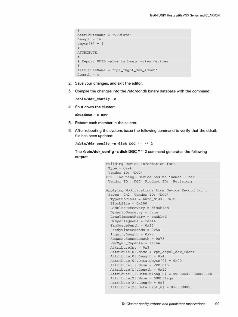
Tru64 UNIX Hosts with VNX Series and CLARiiON
2. Save your changes, and exit the editor.
3. Compile the changes into the /etc/ddr.db binary database with the command:
/sbin/ddr_config -c
4. Shut down the cluster:
shutdown -c now
5. Reboot each member in the cluster.
6. After rebooting the system, issue the following command to verify that the ddr.db file has been updated:
/sbin/ddr_config -s disk DGC '' '' 2
The /sbin/ddr_config -s disk DGC '' '' 2 command generates the following output:
#AttributeName = "VPDinfo"Length = 16ubyte[6] = 4#ATTRIBUTE:## Report UDID value in hwmgr -view devices#AttributeName = "rpt_chgbl_dev_ident"Length = 4
Building Device Information for:Type = diskVendor ID: "DGC"
DDR - Warning: Device has no "name" - forVendor ID : DGC Product ID: Revision:
Applying Modifications from Device Record for :Stype: 0x2 Vendor ID: "DGC"TypeSubClass = hard_disk, RAIDBlockSize = 0x200BadBlockRecovery = disabledDynamicGeometry = trueLongTimeoutRetry = enabledDisperseQueue = falseTagQueueDepth = 0x20ReadyTimeSeconds = 0x5aInquiryLength = 0x78RequestSenseLength = 0x78PwrMgmt_Capable = falseAttributeCnt = 0x3Attribute[0].Name = rpt_chgbl_dev_identAttribute[0].Length = 0x4Attribute[0].Data.ubyte[0] = 0x00Attribute[1].Name = VPDinfoAttribute[1].Length = 0x10Attribute[1].Data.ulong[0] = 0x0004000000000000Attribute[2].Name = DSBLflagsAttribute[2].Length = 0x4Attribute[2].Data.uint[0] = 0x00000008
TruCluster configurations and persistent reservations 99
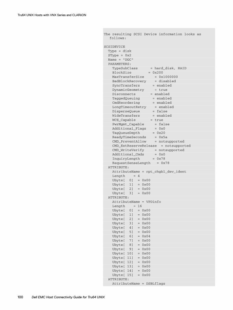
Tru64 UNIX Hosts with VNX Series and CLARiiON
The resulting SCSI Device information looks asfollows:
SCSIDEVICEType = diskSType = 0x2Name = "DGC"PARAMETERS:
TypeSubClass = hard_disk, RAIDBlockSize = 0x200MaxTransferSize = 0x1000000BadBlockRecovery = disabledSyncTransfers = enabledDynamicGeometry = trueDisconnects = enabledTaggedQueuing = enabledCmdReordering = enabledLongTimeoutRetry = enabledDisperseQueue = falseWideTransfers = enabledWCE_Capable = truePwrMgmt_Capable = falseAdditional_Flags = 0x0TagQueueDepth = 0x20ReadyTimeSeconds = 0x5aCMD_PreventAllow = notsupportedCMD_ExtReserveRelease = notsupportedCMD_WriteVerify = notsupportedAdditional_Cmds = 0x0InquiryLength = 0x78RequestSenseLength = 0x78
ATTRIBUTE:AttributeName = rpt_chgbl_dev_identLength = 4Ubyte[ 0] = 0x00Ubyte[ 1] = 0x00Ubyte[ 2] = 0x00Ubyte[ 3] = 0x00
ATTRIBUTE:AttributeName = VPDinfoLength = 16Ubyte[ 0] = 0x00Ubyte[ 1] = 0x00Ubyte[ 2] = 0x00Ubyte[ 3] = 0x00Ubyte[ 4] = 0x00Ubyte[ 5] = 0x00Ubyte[ 6] = 0x04Ubyte[ 7] = 0x00Ubyte[ 8] = 0x00Ubyte[ 9] = 0x00Ubyte[ 10] = 0x00Ubyte[ 11] = 0x00Ubyte[ 12] = 0x00Ubyte[ 13] = 0x00Ubyte[ 14] = 0x00Ubyte[ 15] = 0x00
ATTRIBUTE:AttributeName = DSBLflags
100 Dell EMC Host Connectivity Guide for Tru64 UNIX
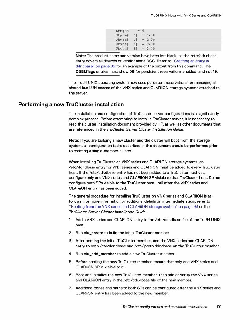
Tru64 UNIX Hosts with VNX Series and CLARiiON
Note: The product name and version have been left blank, as the /etc/ddr.dbase entry covers all devices of vendor name DGC. Refer to “Creating an entry in ddr.dbase” on page 85 for an example of the output from this command. The DSBLflags entries must show 08 for persistent reservations enabled, and not 19.
The Tru64 UNIX operating system now uses persistent reservations for managing all shared bus LUN access of the VNX series and CLARiiON storage systems attached to the server.
Performing a new TruCluster installation
The installation and configuration of TruCluster server configurations is a significantly complex process. Before attempting to install a TruCluster server, it is necessary to read the cluster installation document provided by HP, as well as other documents that are referenced in the TruCluster Server Cluster Installation Guide.
Note: If you are building a new cluster and the cluster will boot from the storage system, all configuration tasks described in this document should be performed prior to creating a single-member cluster.
When installing TruCluster on VNX series and CLARiiON storage systems, an /etc/ddr.dbase entry for VNX series and CLARiiON must be added to every TruCluster host. If the /etc/ddr.dbase entry has not been added to a TruCluster host yet, configure only one VNX series and CLARiiON SP visible to that TruCluster host. Do not configure both SPs visible to the TruCluster host until after the VNX series and CLARiiON entry has been added.
The general procedure for installing TruCluster on VNX series and CLARiiON is as follows. For more information or additional details on intermediate steps, refer to “Booting from the VNX series and CLARiiON storage system” on page 93 or the TruCluster Server Cluster Installation Guide.
1. Add a VNX series and CLARiiON entry to the /etc/ddr.dbase file of the Tru64 UNIX host.
2. Run clu_create to build the initial TruCluster member.
3. After booting the initial TruCluster member, add the VNX series and CLARiiON entry to both /etc/ddr.dbase and /etc/.proto.ddr.dbase on the TruCluster member.
4. Run clu_add_member to add a new TruCluster member.
5. Before booting the new TruCluster member, ensure that only one VNX series and CLARiiON SP is visible to it.
6. Boot and initialize the new TruCluster member, then add or verify the VNX series and CLARiiON entry in the /etc/ddr.dbase file of the new member.
7. Additional zones and paths to both SPs can be configured after the VNX series and CLARiiON entry has been added to the new member.
Length = 4Ubyte[ 0] = 0x08Ubyte[ 1] = 0x00Ubyte[ 2] = 0x00
Ubyte[ 3] = 0x00
TruCluster configurations and persistent reservations 101
Tru64 UNIX Hosts with VNX Series and CLARiiON
Configuring LUNs on the hostThe Tru64 V5.x operating system provides support for up to 255 LUNs per Fibre Channel target. Each Storage Processor presents a single Fibre Channel target.
HBA management
The emxmgr utility can be used to display and manage the Fibre Channel adapters on the host system.
To list all Fibre Channel HBAs, use this command:
emxmgr -d
To display the link status, topology, and port details of a specific adapter, use this command:
emxmgr -t emx?
where emx? is the specific instance number of the adapter, such as emx2.
For more information about this utility, refer to the emxmgr man page.
Device naming
Tru64 V5.x uses dsk device names (departing from the traditional rz device names used in previous versions of the operating system). The device special files are stored in different directories, so the full format of the device name depends on the device type:
◆ Raw devices — /dev/rdisk/dsknnnnz
◆ Block devices — /dev/disk/dsknnnnz
where nnnn is a number starting at 0 for the first device, and z is the partition, ranging from a through h.
Unlike versions of Tru64 prior to V5.0, device names are persistent and do not change when inserting or deleting devices. To permanently delete device names that are no longer used, you must use the hwmgr utility, which is described in the Tru64 UNIX System Administration Manual.
Adding devices
After LUNs have been added to the storage group, it is time to add the devices to yourTru64 host. There are two methods to add devices to the Tru64 system:
◆ Reboot the system
◆ Use the hwmgr utility
The first method works for environments where a reboot is permitted. It is advisable to take an inventory of SCSI devices prior to the reboot using the hwmgr -show scsi command and redirecting the output to a file.
The second method can be performed without interrupting activities on the system. Use the following commands to perform the addition of devices:
hwmgr -scan scsi
102 Dell EMC Host Connectivity Guide for Tru64 UNIX
Tru64 UNIX Hosts with VNX Series and CLARiiON
hwmgr -show scsi
The scan command instructs the system to rescan the SCSI buses for devices, so that the new devices can be found. This command executes asynchronously and can take up to several minutes to complete depending on your CPU and system configuration. You come back to the prompt before the command is completed.
Delay the show command until the scan command has had time to complete. If after a show you do not see all the devices on the system that you expect, wait and repeat the show until the devices are visible.
The hwmgr -show scsi command displays all SCSI devices visible to the system. The output is similar to the following:
There is no direct correlation between the device file name and the logical unit number, as there was in previous releases of the Tru64 operating system. Also, a number of paths in the Num Path column greater than one indicates the existence of multiple paths for all devices shown on SCSI bus 1.
LUN trespassing and path failover
VNX series and CLARiiON storage systems can be configured for high availability by ensuring that there is a separate path from each SP to a HBA on the host system. When configured in this manner, the failure of a path results in the movement of LUNs on the SP in the failed path to the SP on the surviving path. This movement of LUNs is called trespassing.
HWID:SCSIDEVICEID
HOSTNAME DEVICETYPE
DEVICESUBTYPE
DRIVEROWNER
NUMPATH
DEVICEFILE
FIRSTVALID PATH
------------------------------------------------------------------------271:
144 l82ba209 disk none 0 2 dsk203 [1/0/0]
273:
146 l82ba209 disk none 0 1 (null)
275:
3 l82ba209 disk none 0 2 dsk207 [1/0/1]
276:
9 l82ba209 disk none 0 2 dsk208 [1/0/26]
65:
0 l82ba209 disk none 0 1 dsk0 [0/0/0]
66:
1 l82ba209 disk none 0 1 dsk1 [0/1/0]
67:
2 l82ba209 disk none 0 1 dsk2 [0/2/0]
69:
4 l82ba209 cdrom none 0 1 cdrom0 [0/5/0]
129:
64 l82ba209 disk none 2 2 dsk62 [1/0/17]
130:
65 l82ba209 disk none 0 1 (null)
131:
66 l82ba209 disk none 0 2 dsk64 [1/0/2]
132:
67 l82ba209 disk none 0 2 dsk65 [1/0/3]
Configuring LUNs on the host 103
Tru64 UNIX Hosts with VNX Series and CLARiiON
Multipath configurations
If the storage system has been configured for high availability, multiple paths are presented to Tru64 for the same LUN. In these configurations Tru64 can make use of its multipathing ability to improve both reliability and performance.
Tru64 UNIX recognizes multiple paths to VNX series and CLARiiON storage systems automatically as it sees identical WWIDs for the multiple paths to the same LUN. The primary indication for this is the number of paths listed in the hwmgr -show scsi output, as shown earlier. Additional detail is provided in the hwmgr -show scsi -full output.
For example, this command generates the listing that follows it:
hwmgr -show scsi -did 144 -full
LUN expansion
Unisphere/Navisphere offers two methods for expanding VNX series and CLARiiON LUN capacity: RAID group and metaLUN expansion. The AdvFS and UFS file systems on Tru64 UNIX can support expanded LUNs. AdvFS file systems can be extended on hosts with Tru64 UNIX V5.1B or later installed. UFS file systems can be extended on hosts with Tru64 UNIX V5.1 or later installed.
The disk label of an expanded LUN must be updated before the new capacity can be used by file systems. Disk partition sizes can be increased to the new capacity, but the disk offsets of in-use disk partitions must not be changed. The disk label updates should only be done by experienced system administrators. Partitioning and sizing errors in disk label updates can cause data loss. A data backup is recommended before expanding a LUN.
The steps for file system LUN expansion are:
1. Back up data on the LUN to be expanded.
2. Save a copy of the existing disk label:
disklabel -r <dsk_name> > disklabel.orig.out
3. Expand the LUN (using RAID Group or MetaLUN expansion) as detailed in the EMC Navisphere Manager Administrator's Guide.
4. Reread the disk label or run inq to query the new LUN capacity:
disklabel -r <dsk_name>
SCSI DEVICE DEVICE DRIVER NUM DEVICE FIRST HWID: DEVICEID HOSTNAME TYPE SUBTYPE OWNER PATH FILE VALID PATH------------------------------------------------------------------------- 271: 448 182ba209 disk none 0 2 dsk203 [1/0/0]
WWID:01000010:6006-0170-845f-0000-e6a7-6303-2d10-d611
BUS TARGET LUN PATH STATE------------------------------1 0 0 valid 4 0 0 valid
104 Dell EMC Host Connectivity Guide for Tru64 UNIX
Tru64 UNIX Hosts with VNX Series and CLARiiON
5. Rewrite or edit the existing disk label to reflect the new LUN capacity. Increase the size of the disk partition containing the file system to be extended. Do not change the offsets of any disk partitions that are used or open:
disklabel -w <dsk_name>disklabel -re <dsk_name>
6. Extend the file system by remounting with the extend option:
mount -u -o extend <filesystem> <mountpoint>
Configuring LUNs on the host 105

Tru64 UNIX Hosts with VNX Series and CLARiiON
106 Dell EMC Host Connectivity Guide for Tru64 UNIX
PART 3
Part 3 includes:
◆ Appendix A, “Methods of Data Migration”
Appendix

APPENDIX A
This appendix provides guidelines and procedures for system engineers and system administrators who are in the process of planning and implementing a migration of data from existing storage devices to new storage devices in Tru64 UNIX and TruCluster V5 environments.
◆ Tru64 UNIX V5 overview..................................................................................... 110◆ Data migration methods ....................................................................................... 111◆ System and boot device migration ...................................................................... 118◆ Related documentation ...................................................................................... 135
Methods of Data Migration
Methods of Data Migration 109
Methods of Data Migration
Tru64 UNIX V5 overviewThis section provides some background information about disk devices in Tru64 UNIX V5.
Device naming
Tru64 UNIX V5 configures device database entries and device names based on the identifier (WWID) reported by disk devices. New dsk device names and device special files are created only for disk devices that report new and unique identifiers. The dsk device names are independent of bus-target-LUN address and location. A LUN that reports the same identifier as an existing device in the device database is configured as an additional path to the existing device. Since all Symmetrix and VNX series and CLARiiON systems will report unique identifiers, a new dsk device name will be created if an existing Symmetrix or VNX series and CLARiiON device is removed and replaced by a new device at the same bus-target-LUN address. System administrators can use the dsfmgr command to manage device special files and rename devices. The hwmgr commands can be used to view devices, dsk names, and WWID information.
Disk labels
The label of a disk device contains information such as the type, geometry, and partition table of the disk. The disk label is usually located on block 0 (zero) of the disk. The disklabel command can be used to view or configure the partitions and boot block of a disk device. The fstype values in the partition table of a disk label indicate whether a disk partition is available for use or marked in use for Logical Storage Manager (LSM), a file system, or swap space:
◆ Devices that are not being used for file systems or LSM volumes will usually be unlabeled or have unused in the fstype field of all partitions.
◆ Device partitions used in LSM will have LSMnopriv, LSMpriv, LSMpubl, or LSMsimp in the fstype field.
◆ Device partitions used for UFS will have 4.2BSD in the fstype field.
◆ Device partitions used for Advanced File System (AdvFS) will have AdvFS in the fstype field.
Logical Storage Manager
Tru64 UNIX Logical Storage Manager (LSM) software provides the ability to create disk groups and concatenated, striped, or mirrored volumes. LSM volumes are virtual disk devices that use individual disk devices or disk partitions as underlying storage. Volumes can be used for file systems or as raw devices. The functionality and configuration of LSM is similar to Veritas Volume Manager. Additional software licenses are required for the mirroring, striping, and graphical user interface capabilities of LSM.
110 Dell EMC Host Connectivity Guide for Tru64 UNIX
Methods of Data Migration
Advanced File System
Tru64 UNIX Advanced File System (AdvFS) is a log-based file system with a two-layer domain and fileset structure. AdvFS domains are user-defined pools of storage consisting of one or more disk partitions or LSM volumes. AdvFS filesets, which are mountable file system directories equivalent to traditional UNIX file systems, can be created from defined AdvFS domains. Each domain can have one or more filesets. The showfsets command can be used to view the filesets of a particular domain. The /etc/fdmns directory contains subdirectories for each AdvFS domain defined on the host system. Each domain name subdirectory contains links to the disk partitions or LSM volumes that make up the domain. The AdvFS Utilities software license enables the fileset cloning and multiple-device domain capabilities of AdvFS.
Data migration methodsThe migration of data to new storage in Tru64 UNIX V5 environments entails using new devices that have new dsk device special files. Any dependencies or references that hosts and applications may have to the original disk devices and dsk device files must be evaluated and resolved. The data migration methods in this paper can be used to migrate individual disk devices, LSM volumes, and file systems. Since hosts and applications can have dependencies or references to more than one device or file system, system engineers and system administrators may need to coordinate the migration of multiple devices and file systems. In deciding on a suitable data migration method to implement, device usage and data availability are important considerations.
Note: This section describes the various possible methods of migrating nonsystem data (such as user or application data) to new storage devices in Tru64 UNIX and TruCluster V5 host environments. For information on migrating the system and boot devices of Tru64 UNIX or TruCluster V5 hosts, refer to “Tru64 UNIX V5 system and boot device migration” on page 118.
Migration of file systems using vdump/vrestore
This migration procedure uses the vdump command to perform a full backup of a source file system. The procedure also uses the vrestore command to restore the data to a target file system on new storage devices. Although the vdump and vrestore commands are the backup and restore utilities for AdvFS filesets, the commands are file-system independent. These commands can also be used to back up and restore UFS file systems. By using the vdump and vrestore commands in a pipeline expression, no intermediate tape device is needed to migrate the file system data to new storage devices.
Guidelines and notes Note the following:
◆ This procedure is applicable for migration of AdvFS filesets and UFS file systems to new storage devices. The commands work at the file level and are independent of the underlying storage used for the file systems. The source and target file systems can use disk partitions or LSM volumes as the underlying storage.
Data migration methods 111
Methods of Data Migration
◆ To ensure consistent data on the target file system, the original source file system data should not be modified while the vdump or vrestore command is running. The source file system should be idle with no activity or mounted as read-only.
◆ With the optional AdvFS Utilities software license, the AdvFS clonefset utility can be used to create a clone fileset. A clone fileset is a read-only point-in-time snapshot of an existing fileset. A clone fileset could be specified as the source fileset of a vdump/vrestore data migration. This would allow the original fileset data to be available for ongoing processing activity while the static and consistent clone fileset snapshot is used for the migration. However, any updates to the original fileset data after the fileset is cloned will not be migrated to the target file system.
◆ AdvFS domains can have more than one fileset. When using vdump or vrestore, each fileset in the same domain must be migrated individually.
◆ vdump/vrestore should be performed with root user privileges.
Migration procedureand example
The migration steps are:
◆ Use a new disk device (or LSM volume) to create a new target UFS file system or AdvFS domain and fileset. Optionally, if the original source AdvFS domain has more than one fileset, create a fileset in the new target domain for each original fileset to be migrated. For example:
disklabel -r <new_device>disklabel -z <new_device>disklabel -rw <new_device> defaultshowfsets <source_domain_name> (AdvFS only)mkfdmn <new_device> <new_domain_name> (AdvFS only)mkfset <new_domain_name> <source_fileset_name> (AdvFS only)newfs <new_device> (UFS only)
◆ Create a mount-point directory and mount the new target file system. If the original source AdvFS domain has more than one fileset, create mount-point directories and mount each fileset to be migrated. For example:
mkdir <target_mount_dir>mount <new_domain_name>#<source_fileset_name> <target_mount_dir>(AdvFS only)mount <new_device> <target_mount_dir> (UFS only))
◆ Stop activity on the source file system or mount it read-only. Migrate the data from the source file system to the new target file system. Each AdvFS fileset in the domain must be migrated individually. For example:
vdump -0f - <source_mount_dir> | vrestore -xf - -D <target_mount_dir>
◆ Transition the host and applications to the newly migrated file system(s). To make the change transparent to applications and users, mount the new file systems to the original mount-point directories:
a. Unmount the source and new file systems:
umount <source_mount_dir>umount <target_mount_dir>
b. Change to the new file system by editing the device, LSM volume, or AdvFS domain fileset names that are paired to the original mount-point directories in the /etc/fstab file:
112 Dell EMC Host Connectivity Guide for Tru64 UNIX
Methods of Data Migration
vi /etc/fstab (Edit and specify new file system)
If all filesets of an AdvFS domain have been migrated, another option is to replace the original source domain subdirectory in /etc/fdmns with new device links. The /etc/fstab file does not need to be edited if the new file system will reuse the original source domain and fileset names.
mv /etc/fdmns/<source_domain_name>/etc/fdmns/<source_domain_backup>mv /etc/fdmns/<new_domain_name> /etc/fdmns/<source_domain_name>
If the source and new file systems both use equivalent disk partitions, an alternative is to swap the dsk device name files of the old and new disk devices. The /etc/fstab file and /etc/fdmns domain subdirectory device links do not need to be updated if the new file system devices will reuse the original dsk device name files.
For example:
dsfmgr -e <new_device> <old_device>c. Mount the new file systems to the original mount-point directories. Use the new
file system names or reuse the original names as decided in Step b. The file system names to specify should be the same as in the /etc/fstab file. For example:
mount <domain_name>#<fileset_name> <source_mount_dir> (AdvFSonly)mount <device> <source_mount_dir> (UFS only)
◆ Temporary mount-point directories and /etc/fdmns subdirectories with invalid device links can be deleted after the migration has completed.
In the following example, the AdvFS fileset data01_dmn#fs01 at /fs01_mnt is migrated to new device dsk201.
# disklabel -z dsk201# disklabel -rw dsk201 default# mkfdmn /dev/disk/dsk201c new_data01_dmn# mkfset new_data01_dmn fs01# mkdir /target_fs01_mnt# mount -t advfs new_data01_dmn#fs01 /target_fs01_mnt# vdump -0f - /fs01_mnt | vrestore -xf - -D /target_fs01_mnt# umount /fs01_mnt# umount /target_fs01_mnt# mv /etc/fdmns/data01_dmn /etc/fdmns/old_data01_dmn# mv /etc/fdmns/new_data01_dmn /etc/fdmns/data01_dmn# mount -t advfs data01_dmn#fs01 /fs01_mnt
Migration of AdvFS domains using addvol/rmvol
This migration procedure uses the AdvFS addvol command to add new storage devices to an existing AdvFS domain. The procedure uses the rmvol command to remove the old storage devices from the domain. The rmvol command will automatically migrate the file system data in the domain to new devices as the old devices are removed.
Data migration methods 113
Methods of Data Migration
Guidelines and notes Note the following:
◆ This procedure is applicable for migration of AdvFS domains to new storage devices. A domain can contain more than one AdvFS fileset.
◆ AdvFS domains are made up of one or more disk partitions or LSM volumes. Ensure that there is enough free space in the newly added storage device(s) to hold the data to be migrated from the old storage device(s).
◆ All filesets in an AdvFS domain must be mounted before devices can be removed from the domain. The rmvol command will fail if any filesets in the domain are not mounted.
◆ Adding and removing the underlying storage devices of an AdvFS domain does not affect the logical directory structure of the filesets in the domain. The fileset file systems remain active and usable during the migration. The data migration will be completed when the rmvol command completes and all old devices have been removed.
◆ The AdvFS addvol and rmvol commands require the AdvFS Utilities software license. The commands must be run as root user.
Migration procedureand example
The migration steps are:
1. Use the showfdmn command to view the properties of the AdvFS domain to be migrated, and note the amount of free and used disk space:
showfdmn <domain_name>
2. Verify that all filesets in the AdvFS domain are mounted. View the filesets in the domain with the showfsets command, and mount any filesets that have not already been mounted:
showfsets <domain_name>
3. Configure new disk devices (or LSM volumes) that are large enough to replace the old devices. Label each new disk device. If migrating to a LSM volume, create the LSM volume with the new devices. For example:
disklabel -r <new_device>disklabel -z <new_device>disklabel -rw <new_device> default
4. Add the new device (or LSM volume) to the AdvFS domain. If necessary, more than one new device can be added to the domain. For example:
addvol <new_device> <domain_name>
5. Remove the old device(s) with the rmvol command:
rmvol <old_device> <domain_name>
The data migration will be completed when the rmvol command completes and all old devices have been removed.
6. Optionally, check and verify the AdvFS domain after the data migration has completed. For example:
showfdmn <domain_name>umount <mount_dir>
114 Dell EMC Host Connectivity Guide for Tru64 UNIX
Methods of Data Migration
/sbin/advfs/verify <domain_name>mount –t advfs <domain_name>#<fileset_name> <mount_dir>
In the following example, the AdvFS domain data02_dmn is migrated from old device dsk102 to new device dsk202:
# showfdmn data02_dmn# showfsets data02_dmn# disklabel -z dsk202# disklabel -rw dsk202 default# addvol /dev/disk/dsk202c data02_dmn# rmvol /dev/disk/dsk102c data02_dmn# showfdmn data02_dmn# umount /fs02_mnt# /sbin/advfs/verify data02_dmn# mount -t advfs data02_dmn#fs02 /fs02_mnt
Data migration using LSM mirroring
This migration procedure copies the data of an existing LSM volume to new storage devices by using LSM host-based data mirroring capabilities. The new storage devices are initialized for LSM and used to create a new mirror plex for an existing LSM volume. When the new plex is attached, LSM copies the volume data from the original data plex to the new plex and synchronizes the mirrors. After the mirror plexes are fully synchronized, the original plex is detached from the LSM volume, and the old storage devices are removed.
Guidelines and notes Note the following:
◆ This procedure is applicable for migration of LSM volume data to new storage devices.
◆ Data that is not in an existing LSM volume can be encapsulated or migrated into an LSM volume. The volencap and volreconfig commands can be used to encapsulate the data in disk devices, disk partitions, or AdvFS domains into LSM volumes. The disk device or domain cannot be mounted or in use during the encapsulation process. In Tru64 UNIX V5.1A and later, the volmigrate command can be used to migrate the data in AdvFS domains into LSM volumes.
◆ The LSM volume remains active and usable during the mirroring and synchronization process.
◆ The LSM mirroring feature requires an LSM software license.
Migration procedureand example
The migration steps are:
1. View the existing LSM configuration. Note the layout, plex sizes, disk partitions, and disk group of the LSM volume to be migrated. Type the following command:
volprint -ht
2. Select new disk devices or disk partitions that are large enough to replace the old storage devices. Label each disk device. For example:
disklabel -r <new_device>disklabel -z <new_device>disklabel -rw <new_device> default
3. Initialize the new disk devices or disk partitions for LSM. Add the new disk devices or disk partitions to the disk group of the LSM volume to be migrated.
Data migration methods 115
Methods of Data Migration
For example:
voldisksetup -i <new_device>voldg -g <disk_group_name> adddisk <new_device>
4. Mirror the LSM volume by typing the following command. Include multiple new devices or partitions for the new mirror plex if necessary. Since this process may take a long time to complete, the command can be run in the background.
volassist -g <disk_group_name> mirror <volume_name> <new_devices> &
5. When the LSM volume mirror plexes are fully synchronized, the old storage device plex can be disassociated by typing the following:
volprint -htg <disk_group_name> <volume_name>volplex -g <disk_group_name> dis <old_plex_name>
6. After the migration has successfully completed, the old storage devices can be removed from LSM by typing the following:
voledit -g <disk_group_name> -r rm <old_plex_name>voldisk rm <old_device>
In the following example, the LSM volume data03_vol in disk group data03_dg is migrated from old device dsk103 to new device dsk203:
# volprint -ht# disklabel -z dsk203# disklabel -rw dsk203 default# voldisksetup -i dsk203# voldg -g data03_dg adddisk dsk203# volassist -g data03_dg mirror data03_vol dsk203 &# volprint -htg data03_dg data03_vol# volplex -g data03_dg dis data03_vol-01# voledit -g data03_dg -r rm data03_vol-01# voldisk rm dsk103
Storage-based data migrationA storage-based data migration may be possible if the old and new storage devices are on the same or compatible storage arrays. The mirror and split operations of Dell EMC TimeFinder™ and Dell EMC SRDF™ can be used to copy and migrate data between Symmetrix device pairs. For VNX series and CLARiiON storage systems, Dell EMC MirrorView™ can be used to create mirrors between various types of VNX series and CLARiiON systems (FC4700 and the CX-series). Once the mirror has synchronized, it can be fractured, which is the equivalent of splitting the mirror pair. Then, the secondary image is promoted to make it accessible by a host server. Host applications and users must be transitioned over to the new storage devices when the data migration is completed.
Guidelines and notes Note the following:
◆ This procedure is applicable for migration of disk data to new storage devices.
116 Dell EMC Host Connectivity Guide for Tru64 UNIX
Methods of Data Migration
◆ Disk devices that have data relationships or dependencies should be mirrored concurrently and split at the same time. All devices in the same LSM disk group must be copied together. All devices in the same AdvFS domain must be copied together. Similar data relationships or dependencies between multiple disk devices may also exist at the host application level.
◆ Before transitioning over to the new devices, any host applications that access the original source devices should be stopped, and the original source devices should be unmounted and deported. The device pair mirrors should be split while the original source devices are idle and not in use. After the split completes, host applications and users can be transitioned over to the new devices by configuring the new devices with the original file system mount-point directories and/or dsk device name files.
◆ The dsk device names of the new devices will be different than the original device names. Reassigning the original device name files to the new devices is a simple way to transition over to the new devices with minimal reconfiguration. Type the following:
dsfmgr -e <new_dsk_name> <original_dsk_name>
◆ If the original disk device is a UFS file system device, an alternative to renaming the new device with dsfmgr is editing the new device name into the corresponding /etc/fstab file entry.
◆ If the original disk devices are AdvFS domain devices, an alternative to renaming the new devices is modifying the device links in the domain subdirectory under /etc/fdmns. To replace the old device links with new device links, type:
cd /etc/fdmns/<domain_name>rm <old_device>ln -s <new_device>
◆ If the original disk devices are LSM devices, the LSM disk group that has been copied must be restored with saved LSM configuration information. The disk group cannot be simply imported because LSM will reject cloned devices. To prevent problems that may occur if the original LSM devices and cloned devices are both accessible at the same time, the original devices should be disconnected before the new device copies are made available to the host.
◆ All file systems on the new devices should be checked or verified before they are remounted to their original mount-point directories. Type the following:
fsck <device_or_volume> (UFS only)/sbin/advfs/verify <domain_name> (AdvFS only)
Data migration methods 117
Methods of Data Migration
Migration procedurefor LSM devices
The migration steps are:
1. Establish mirrors for all devices in the same LSM disk group.
2. Save the LSM configuration with volsave:
volsave -d <lsm_save_dir>
3. Stop activity, unmount any file systems, and deport the LSM disk group:
voldg deport <disk_group_name>
4. Disconnect or take offline the original LSM devices to make them unavailable.
5. Split the mirrors of all devices in the LSM disk group to create the disk group copy.
6. Reassign the dsk device name files of the original LSM devices to the new devices:
dsfmgr -m <new_dsk_name> <original_dsk_name>
7. Restore the LSM disk group and enable the volumes. For example, type:
voldisk rm <original_dsk_names>volrestore -f -g <disk_group_name> -d <lsm_save_dir>volume start <volume_names>
8. Check/verify any file systems, remount them to the original mount-point directories, and resume activity.
System and boot device migrationThe file systems and data on system and boot devices are essential for the normal startup and operation of a Tru64 UNIX or TruCluster host. As new storage devices are usually assigned new dsk device names, some configuration updates are necessary to ensure that the host can boot and operate properly from new system and boot devices.
Tru64 UNIX V5 system and boot device migration
This section provides information on migrating the system and boot device data of standalone non-clustered Tru64 UNIX V5 hosts to new storage devices.
Non-clustered Tru64 UNIX V5 hosts have the following system and boot devices:
◆ Boot and root (/) file system
The boot device holds the boot block and the root (/) file system. The root file system of non-clustered hosts can be either AdvFS or UFS. The boot device is referenced in the /etc/fdmns/root domain directory device link or in the /etc/fstab file. The boot device is also referenced in the bootdef_dev system console variable. The root, /usr, and /var file systems of a host may be configured on separate disk partitions of the same disk device, or each file system may be configured on different disk devices or volumes. The root file system must be on the a or c partition of a disk device.
118 Dell EMC Host Connectivity Guide for Tru64 UNIX
Methods of Data Migration
◆ /usr file system
One or more devices (or volumes) hold the /usr file system. The /usr file system of non-clustered hosts can be either AdvFS or UFS. The /usr file system devices are referenced in the /etc/fdmns/usr_domain directory device links or in the /etc/fstab file.
◆ /var file system
One or more devices (or volumes) hold the /var file system. The /var file system of non-clustered hosts can be either AdvFS or UFS. The /var file system devices are referenced in the /etc/fdmns/usr_domain or /etc/fdmns/var_domain directory device links or in the /etc/fstab file.
◆ Swap space
A host may use one or more devices as swap space. Swap devices can be configured with the swapon command and defined in the /etc/sysconfigtab file.
In order to boot and operate properly from new system and boot devices, the following configuration files and references may need to be updated:
◆ /etc/fstab file
The /etc/fstab entries specify the file systems that will be mounted when the host is booted.
◆ /etc/fdmns directory
If AdvFS file systems are used, the /etc/fdmns subdirectories will contain device links for root domain, usr domain, and var domain.
◆ /etc/sysconfigtab file
The swapdevice attribute specifies the swap devices.
◆ dsk device name files
You can use the dsfmgr command to change or reassign the device special files of disk devices.
◆ Boot block on boot device
The boot device must have a valid boot block. You can use the disklabel command and –t option flag to write a boot block.
◆ bootdef_dev console variable
This console-level variable defines the disk device from which the system console will attempt to boot. You can use the following commands to determine the console name of a boot device:
wwidmgr –quickset –udid <id>show dev
You can migrate the system and boot device data of non-clustered Tru64 UNIX V5 hosts using the methods described earlier in this paper. However, note the following:
◆ If you use the vdump/vrestore procedure to migrate the root file system to a new boot device, a boot block must be written to the new boot device.
System and boot device migration 119
Methods of Data Migration
◆ You can use the AdvFS addvol and rmvol procedure only for the /usr and /var file system domains. You cannot use the addvol command to add devices to root domain.
◆ The volrootmir command is a special LSM command for mirroring the boot device of non-clustered hosts.
◆ The storage-based data migration procedure is not recommended for migrating system and boot devices that are LSM volumes.
Migration procedureand example
The migration steps are:
1. Identify the existing Tru64 UNIX system and boot devices. Configure and discover the new storage devices. Determine the device names and WWIDs of the new system and boot devices. Type the command:
hwmgr -show scsi -full
2. Migrate the root (/), /usr, and /var file systems to the new devices.
3. Depending on the method used to migrate the system and boot devices, the new root file system may need to be updated to reference the new devices. If necessary, mount the new root file system and modify the /etc/fstab file, /etc/sysconfigtab file, or /etc/fdmns subdirectories on the new root file system.
4. Shut down the Tru64 host and disconnect/take offline the old system and boot devices. Type:
shutdown -h now
5. Set the new boot device at the system console and boot from the new device. If the boot fails, update the configuration files on the new root file system by booting to single-user mode (boot –fl s) or by booting an alternate boot device from which the new root file system can be temporarily mounted. For example:
wwidmgr -clear allwwidmgr -show wwid | morewwidmgr -quickset -udid <boot_device_udid>initshow devset bootdef_dev <boot_device_console_name>boot
TruCluster V5 system and boot device migration
This section provides information on migrating the system and boot device data of TruCluster V5 member hosts to new storage devices.
TruCluster V5 cluster members have the following system and boot devices:
◆ cluster_root file system
One or more disk partitions (or LSM volumes) are used for the clusterwide root (/) file system in the AdvFS cluster_root domain. The disk partitions or volumes are referenced in the /etc/fdmns/cluster_root directory device links and in the cnx partition of the member boot and quorum devices. You can configure the clusterwide file system domains on separate disk partitions of the same disk
120 Dell EMC Host Connectivity Guide for Tru64 UNIX
Methods of Data Migration
device, or configure each domain on different disk devices or volumes. The devices allocated for the clusterwide file system domains should be shared and connected to all cluster members for high availability.
◆ cluster_usr file system
One or more disk partitions (or LSM volumes) are used for the clusterwide /usr file system in the AdvFS cluster_usr domain. The disk partitions or volumes are referenced in the /etc/fdmns/cluster_usr directory device links.
◆ cluster_var file system
One or more disk partitions (or LSM volumes) are used for the clusterwide /var file system in the AdvFS cluster_var domain. The disk partitions or volumes are referenced in the /etc/fdmns/cluster_var directory device links.
◆ Cluster quorum
Some clusters may use a cluster quorum disk. A quorum disk is optional but recommended. The quorum disk device is configured with the clu_quorum command and referenced in each member’s /etc/sysconfigtab file. The quorum disk device can be very small, so a Symmetrix gatekeeper device may be used as the quorum disk. The quorum disk device should not be used for any other data or purposes. The device must be shared and connected to all cluster members.
◆ Member boot and root domain
Each cluster member has a boot device. The member boot device holds the boot block and a root domain file system for member-specific data and files. The member-specific root domain subdirectory in /etc/fdmns contains a link to partition a of the boot device. The boot device is also referenced in the member’s /etc/sysconfigtab file and in the bootdef_dev system console variable. Member boot devices should not be used for any other data or purposes. The devices should be shared and available to all cluster members.
◆ Member swap space
Each cluster member may use one or more devices as swap space. Swap devices can be configured with the swapon command and defined in the member’s /etc/sysconfigtab file.
In order to boot and operate properly from new system and boot devices, the following configuration files and references may need to be updated:
◆ /etc/fstab file
The /etc/fstab entries specify the file systems that will be mounted when the host is booted.
◆ /etc/fdmns directory
The AdvFS domain subdirectories contain device links for the cluster_root, cluster_usr, cluster_var, and member-specific root domains.
◆ /etc/sysconfigtab member files
These member-specific files contain attribute values for the following devices:
– cnx partition on boot device of the cluster member:
System and boot device migration 121
Methods of Data Migration
clubase: cluster_seqdisk_major and cluster_seqdisk_minor– cnx partition on the cluster quorum device:
clubase: cluster_qdisk_major and cluster_qdisk_minor– the cluster member swap devices:
vm:swapdevice
You can use the clu_quorum command to set the quorum device and quorum vote attributes in /etc/sysconfigtab. You can determine the major and minor numbers of the device cnx partitions (h partitions) using the file or ls –l command.
◆ cnx partition of member boot and quorum devices
The cnx partition information specifies the disk device or volume that contains the cluster_root file system. You can use the clu_bdmgr command to read and write the cnx partition (h partition) of member boot and quorum devices.
You can update the cnx partition with new cluster_root device information by specifying the device attributes cfs:cluster_root_dev1_maj and cluster_root_dev1_min in an interactive boot.
◆ dsk device name files
You can use the dsfmgr command to change or reassign the device special files of disk devices.
◆ Boot block on boot devices
Member boot devices must have a valid boot block. You can write a boot block using the disklabel command and –t option flag.
◆ bootdef_dev console variable
This console-level variable defines the disk device from which the system console will attempt to boot. You can determine the console name of a boot device with the wwidmgr –quickset –udid <id> and show dev commands.
You can migrate the TruCluster V5 system and boot device data using the methods described earlier in this paper. However, note the following:
◆ You can use the AdvFS addvol and rmvol procedure only on the clusterwide file system domains. You cannot use the addvol command on the member boot device and member-specific root domain. The quorum and member swap devices do not have AdvFS file systems.
◆ You can use the LSM mirroring procedure for the cluster_usr and cluster_var domains. LSM can be used for the cluster_root domain and member swap devices only with TruCluster V5.1A and later. You cannot use LSM for the member boot and quorum devices.
◆ The storage-based data migration procedure is not recommended for migrating system and boot devices that are LSM volumes.
122 Dell EMC Host Connectivity Guide for Tru64 UNIX
Methods of Data Migration
◆ An interactive boot is necessary if the new system and boot devices were copied using storage-based data migration. Otherwise, booting from the new devices will fail or hang because the configuration files on the new devices are still based on the old storage device attributes.
During the interactive boot, you must specify the major and minor numbers of the new member's boot and cluster_root devices. Use an existing cluster member to discover the new devices and configure them prior to the data migration. In this process, note the major and minor numbers of the target member's boot and cluster_root devices.
If the new device attributes were not determined before switching to the new system and boot devices, refer to the section “Recovering the Cluster Root File System to a New Dis” in the “Troubleshooting Clusters” chapter of the TruCluster V5 Cluster Administration Manual. See the example procedure that copies the cluster’s hardware database files to an alternate system boot disk from which the new disk devices and attributes can be discovered.
Host-based migration procedure and exampleThe host-based migration steps are:
1. Identify the existing TruCluster V5 system and boot devices. Configure and discover the new storage devices. Determine the device names, major/minor numbers, and WWIDs of the new system and boot devices. For example:
ls /etc/fdmns/clu*ls /etc/fdmns/root*clu_quorumhwmgr -show scsi -fullfile /dev/disk/<dsk_name><partition>
2. Migrate the cluster member boot devices:
a. Write a disk label to the target member boot device. For example:
/sbin/disklabel -z <new_member1_device>/sbin/disklabel -rw -t advfs <new_member1_device> default
b. Initialize the target boot device by using clu_bdmgr with a new unused cluster member id. For example:
/usr/sbin/clu_get_info/usr/sbin/clu_bdmgr -c <new_member1_device> <new_member1_id>
c. Mount the new target root domain fileset:
mkdir /target_member1_mntmount root<new_member1_id>_domain#root /target_member1_mnt
d. After stopping I/O activity, dump the member1 root domain fileset and restore it to the target root domain fileset. For example:
vdump -0f - /cluster/members/member1/boot_partition | vrestore-xf - -D /target_member1_mnt
e. Repeat Step a through Step d with a different target boot device and unused member ID for each additional cluster member.
System and boot device migration 123
Methods of Data Migration
3. Update the cnx partition and /etc/sysconfigtab file of the new member boot devices:
a. In the new target root domain fileset, edit the clu_bdmgr.conf file and specify the new cluster root device partition. For example:
/usr/sbin/clu_bdmgr -d <old_member1_device> > /old_member1.cnxcat /old_member1.cnx | sed"s/<old_root_device>/<new_root_device/g" >/target_member1_mnt/etc/clu_bdmgr.conf
b. Write the updated cnx information to the target member boot device:
/usr/sbin/clu_bdmgr -h <new_member1_device>/target_member1_mnt/etc/clu_bdmgr.conf
c. In the new target root domain fileset, edit the sysconfigtab file and specify the new target device attribute values. For example:
vi /target_member1_mnt/etc/sysconfigtab
swapdevice=/dev/disk/<new_member1_device_swap>cluster_seqdisk_major=<new_member1_device_major>cluster_seqdisk_minor=<new_member1_device_minor>
d. Repeat Step a through Step c for each new member boot device.
4. Migrate the cluster_usr file system device(s) with the following steps:
a. Create a new target cluster_usr domain and fileset with the target device partition(s). For example:
mkfdmn /dev/disk/<new_usr_device> new_cluster_usrmkfset new_cluster_usr usr
b. Mount the target cluster_usr domain fileset. For example:
mkdir /target_usr_mntmount new_cluster_usr#usr /target_usr_mnt
c. After stopping I/O activity, dump the original source cluster_usr fileset to the new target cluster_usr fileset:
vdump -0f - /usr | vrestore -xf - -D /target_usr_mnt
5. Migrate the cluster_var file system device(s):
a. Create a new target cluster_var domain and fileset with the target device partition(s):
mkfdmn /dev/disk/<new_var_device> new_cluster_varmkfset new_cluster_var var
b. Mount the target cluster_var domain fileset:
mkdir /target_var_mntmount new_cluster_var#var /target_var_mnt
c. After stopping I/O activity, dump the original source cluster_var fileset to the new target cluster_var fileset:
vdump -0f - /var | vrestore -xf - -D /target_var_mnt
6. Migrate the cluster_root file system device(s).
124 Dell EMC Host Connectivity Guide for Tru64 UNIX
Methods of Data Migration
a. Create a new target cluster_root domain and fileset using the target root device partition(s):
mkfdmn /dev/disk/<new_root_device> new_cluster_rootmkfset new_cluster_root root
b. Mount the target cluster_root fileset:
mkdir /target_root_mntmount new_cluster_root#root /target_root_mnt
c. After stopping I/O activity, dump the original source cluster_root fileset to the new target cluster_root fileset:
vdump -0f - / | vrestore -xf - -D /target_root_mnt
7. In the new target cluster_root fileset, replace the AdvFS cluster_root, cluster_usr, cluster_var, and member-specific root domain device links in /etc/fdmns. For example:
cd /target_root_mnt/etc/fdmns/mv cluster_root old_cluster_rootmv new_cluster_root cluster_rootmv cluster_usr old_cluster_usrmv new_cluster_usr cluster_usrmv cluster_var old_cluster_varmv new_cluster_var cluster_varmv root1_domain old_root1_domainmv root<new_member1_id>_domain root1_domainmv root2_domain old_root2_domainmv root<new_member2_id>_domain root2_domain
8. Shut down the cluster. All members must be shut down. Type the command:
shutdown -c now
9. Set bootdef_dev to the new member boot device and boot each cluster member. For example:
wwidmgr -clear allwwidmgr -show wwid | morewwidmgr -quickset -udid <boot_device_udid>initshow devset bootdef_dev <boot_device_console_name>boot
10. Configure a new quorum device and new swap devices if necessary:
a. Remove the old quorum device:
clu_quorum -f -d remove
b. Create and add the new quorum device:
clu_quorum -f -d add <new_quorum_device> <quorum_device_votes>
c. Edit each member’s sysconfigtab file to specify swap devices:
vi /etc/sysconfigtabswapdevice=<new_swap_devices>
System and boot device migration 125
Methods of Data Migration
11. Verify that the new storage devices are referenced in all TruCluster system and boot device configuration files and attributes. Remove the old storage devices. Optionally, reboot to ensure that each cluster member can boot independently from the new system and boot devices without any problem.
In the following example, the TruCluster V5 system and boot devices are migrated with the vdump/vrestore procedure.
Identify the original TruCluster system and boot device configuration
# clu_get_infoCluster information for cluster truclu100
Number of members configured in this cluster = 2memberid for this member = 1Quorum disk = dsk1286hQuorum disk votes = 1Information on each cluster member
Cluster memberid = 1Hostname = truclu101Cluster interconnect IP name = truclu101-mc0Member state = UP
Cluster memberid = 2Hostname = truclu102Cluster interconnect IP name = truclu102-mc0Member state = UP
# ls /etc/fdmns/cluster*/etc/fdmns/cluster_root:dsk1307c
/etc/fdmns/cluster_usr:dsk1308c
/etc/fdmns/cluster_var:dsk1310c
# ls /etc/fdmns/root*/etc/fdmns/root1_domain:dsk1311a
/etc/fdmns/root2_domain:dsk1312a
Get the major/minor numbers of the target device partitions
# file /dev/disk/dsk1547h/dev/disk/dsk1547h: block special (19/27618)# ls -l /dev/disk/dsk1547hbrw------- 1 root system 19,27618 May 30 08:49 /dev/disk/dsk1547h# file /dev/disk/dsk1593h/dev/disk/dsk1593h: block special (19/28354)# file /dev/disk/dsk1594h/dev/disk/dsk1594h: block special (19/28370)
Migrate member1 boot disk
# disklabel -z dsk1593# disklabel -rw -t advfs dsk1593 default# clu_bdmgr -c dsk1593 3
*** Error ***Bad disk label.
126 Dell EMC Host Connectivity Guide for Tru64 UNIX
Methods of Data Migration
Creating AdvFS domains:Creating AdvFS domain 'root3_domain#root' on partition '/dev/disk/dsk1593a'.
# mkdir /target_member1_mnt# mount root3_domain#root /target_member1_mnt# vdump -0f - /cluster/members/member1/boot_partition | vrestore -xf - -D /target_member1_mntpath : /cluster/members/member1/boot_partitiondev/fset : root1_domain#roottype : advfsadvfs id : 0x31b6d762.000c6ac6.1vdump: Date of last level 0 dump: the start of the epochvdump: Dumping directoriesvdump: Dumping 49785118 bytes, 3 directories, 22 filesvdump: Dumping regular filesvrestore: Date of the vdump save-set: Sat Jun 8 07:29:55 1996vrestore: Save-set source directory : /cluster/members/member1/boot_partitionvrestore: warning: vdump/vrestore of quotas not supported for non local filesystems.
vdump: Status at Sat Jun 8 07:29:58 1996vdump: Dumped 49785118 of 49785118 bytes; 100.0% completedvdump: Dumped 3 of 3 directories; 100.0% completedvdump: Dumped 22 of 22 files; 100.0% completedvdump: Dump completed at Sat Jun 8 07:29:58 1996
Update the cnx partition and /etc/sysconfigtab file on the new member1 boot device
# clu_bdmgr -d dsk1311 > /clu_mig/old_member1.cnx# cat /clu_mig/old_member1.cnx | sed "s/dsk1307/dsk1588/g" >/target_member1_mnt/etc/clu_bdmgr.conf# clu_bdmgr -h dsk1593 /target_member1_mnt/etc/clu_bdmgr.conf# clu_bdmgr -d dsk1593# clu_bdmgr configuration file# DO NOT EDIT THIS FILE::TYP:m:CFS:/dev/disk/dsk1588c::
# vi /target_member1_mnt/etc/sysconfigtab
vm:swapdevice=/dev/disk/dsk1593b
clubase:cluster_seqdisk_major=19cluster_seqdisk_minor=28354
Migrate member2 boot device
# disklabel -z dsk1594Disk is unlabeled or, /dev/rdisk/dsk1594c is not in block 0 of the disk# disklabel -rw -t advfs dsk1594 default# clu_bdmgr -c dsk1594 4
*** Error ***Bad disk label.
Creating AdvFS domains:Creating AdvFS domain 'root4_domain#root' on partition '/dev/disk/dsk1594a'.
# mkdir /target_member2_mnt# mount root4_domain#root /target_member2_mnt# vdump -0f - /cluster/members/member2/boot_partition | vrestore -xf - -D /target_member2_mntpath : /cluster/members/member2/boot_partitiondev/fset : root2_domain#roottype : advfsadvfs id : 0x31b6e7c7.01067414.1vdump: Date of last level 0 dump: the start of the epoch
System and boot device migration 127
Methods of Data Migration
vdump: Dumping directoriesvrestore: Date of the vdump save-set: Sat Jun 8 08:04:11 1996vrestore: Save-set source directory : /cluster/members/member2/boot_partitionvdump: Dumping 49471966 bytes, 3 directories, 22 filesvdump: Dumping regular filesvrestore: warning: vdump/vrestore of quotas not supported for non local filesystems.
vdump: Status at Sat Jun 8 08:04:16 1996vdump: Dumped 49471966 of 49471966 bytes; 100.0% completedvdump: Dumped 3 of 3 directories; 100.0% completedvdump: Dumped 22 of 22 files; 100.0% completedvdump: Dump completed at Sat Jun 8 08:04:16 1996
Update the cnx partition and /etc/sysconfigtab file on the new member2 boot device
# clu_bdmgr -d dsk1312 > /clu_mig/old_member2.cnx# cat /clu_mig/old_member2.cnx | sed "s/dsk1307/dsk1588/g" >/target_member2_mnt/etc/clu_bdmgr.conf# clu_bdmgr -h dsk1594 /target_member2_mnt/etc/clu_bdmgr.conf# clu_bdmgr -d dsk1594# clu_bdmgr configuration file# DO NOT EDIT THIS FILE::TYP:m:CFS:/dev/disk/dsk1588c::
# vi /target_member2_mnt/etc/sysconfigtab
vm:swapdevice=/dev/disk/dsk1594b
clubase:cluster_seqdisk_major=19cluster_seqdisk_minor=28370
Migrate cluster_usr and cluster_var
# disklabel -rw dsk1589 default# disklabel -rw dsk1590 default# mkfdmn /dev/disk/dsk1589c new_cluster_usr# mkfset new_cluster_usr usr# mkdir /target_usr_mnt# mount new_cluster_usr#usr /target_usr_mnt# vdump -0f - /usr | vrestore -xf - -D /target_usr_mntpath : /usrdev/fset : cluster_usr#usrtype : advfsadvfs id : 0x31b6d7a6.0002897a.1vdump: Date of last level 0 dump: the start of the epochvdump: Dumping directoriesvrestore: Date of the vdump save-set: Sat Jun 8 08:23:10 1996vrestore: Save-set source directory : /usrvdump: Dumping 1125701251 bytes, 1267 directories, 32595 filesvdump: Dumping regular filesvrestore: warning: vdump/vrestore of quotas not supported for non local filesystems.
vdump: Status at Sat Jun 8 08:27:42 1996vdump: Dumped 1127878219 of 1125701251 bytes; 100.2% completedvdump: Dumped 1267 of 1267 directories; 100.0% completedvdump: Dumped 32595 of 32595 files; 100.0% completedvdump: Dump completed at Sat Jun 8 08:27:42 1996
# mkfdmn /dev/disk/dsk1590c new_cluster_var# mkfset new_cluster_var var# mkdir /target_var_mnt# mount new_cluster_var#var /target_var_mnt
128 Dell EMC Host Connectivity Guide for Tru64 UNIX
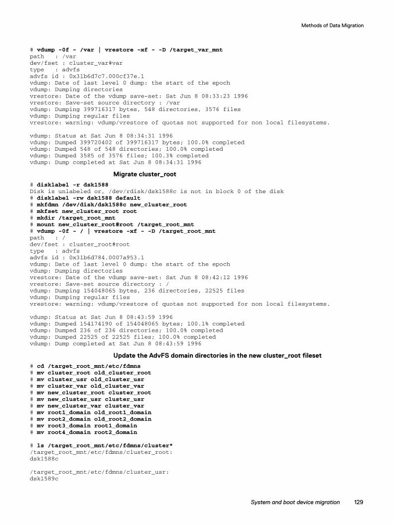
Methods of Data Migration
# vdump -0f - /var | vrestore -xf - -D /target_var_mntpath : /vardev/fset : cluster_var#vartype : advfsadvfs id : 0x31b6d7c7.000cf37e.1vdump: Date of last level 0 dump: the start of the epochvdump: Dumping directoriesvrestore: Date of the vdump save-set: Sat Jun 8 08:33:23 1996vrestore: Save-set source directory : /varvdump: Dumping 399716317 bytes, 548 directories, 3576 filesvdump: Dumping regular filesvrestore: warning: vdump/vrestore of quotas not supported for non local filesystems.
vdump: Status at Sat Jun 8 08:34:31 1996vdump: Dumped 399720402 of 399716317 bytes; 100.0% completedvdump: Dumped 548 of 548 directories; 100.0% completedvdump: Dumped 3585 of 3576 files; 100.3% completedvdump: Dump completed at Sat Jun 8 08:34:31 1996
Migrate cluster_root
# disklabel -r dsk1588Disk is unlabeled or, /dev/rdisk/dsk1588c is not in block 0 of the disk# disklabel -rw dsk1588 default# mkfdmn /dev/disk/dsk1588c new_cluster_root# mkfset new_cluster_root root# mkdir /target_root_mnt# mount new_cluster_root#root /target_root_mnt# vdump -0f - / | vrestore -xf - -D /target_root_mntpath : /dev/fset : cluster_root#roottype : advfsadvfs id : 0x31b6d784.0007a953.1vdump: Date of last level 0 dump: the start of the epochvdump: Dumping directoriesvrestore: Date of the vdump save-set: Sat Jun 8 08:42:12 1996vrestore: Save-set source directory : /vdump: Dumping 154048065 bytes, 236 directories, 22525 filesvdump: Dumping regular filesvrestore: warning: vdump/vrestore of quotas not supported for non local filesystems.
vdump: Status at Sat Jun 8 08:43:59 1996vdump: Dumped 154174190 of 154048065 bytes; 100.1% completedvdump: Dumped 236 of 236 directories; 100.0% completedvdump: Dumped 22525 of 22525 files; 100.0% completedvdump: Dump completed at Sat Jun 8 08:43:59 1996
Update the AdvFS domain directories in the new cluster_root fileset
# cd /target_root_mnt/etc/fdmns# mv cluster_root old_cluster_root# mv cluster_usr old_cluster_usr# mv cluster_var old_cluster_var# mv new_cluster_root cluster_root# mv new_cluster_usr cluster_usr# mv new_cluster_var cluster_var# mv root1_domain old_root1_domain# mv root2_domain old_root2_domain# mv root3_domain root1_domain# mv root4_domain root2_domain
# ls /target_root_mnt/etc/fdmns/cluster*/target_root_mnt/etc/fdmns/cluster_root:dsk1588c
/target_root_mnt/etc/fdmns/cluster_usr:dsk1589c
System and boot device migration 129
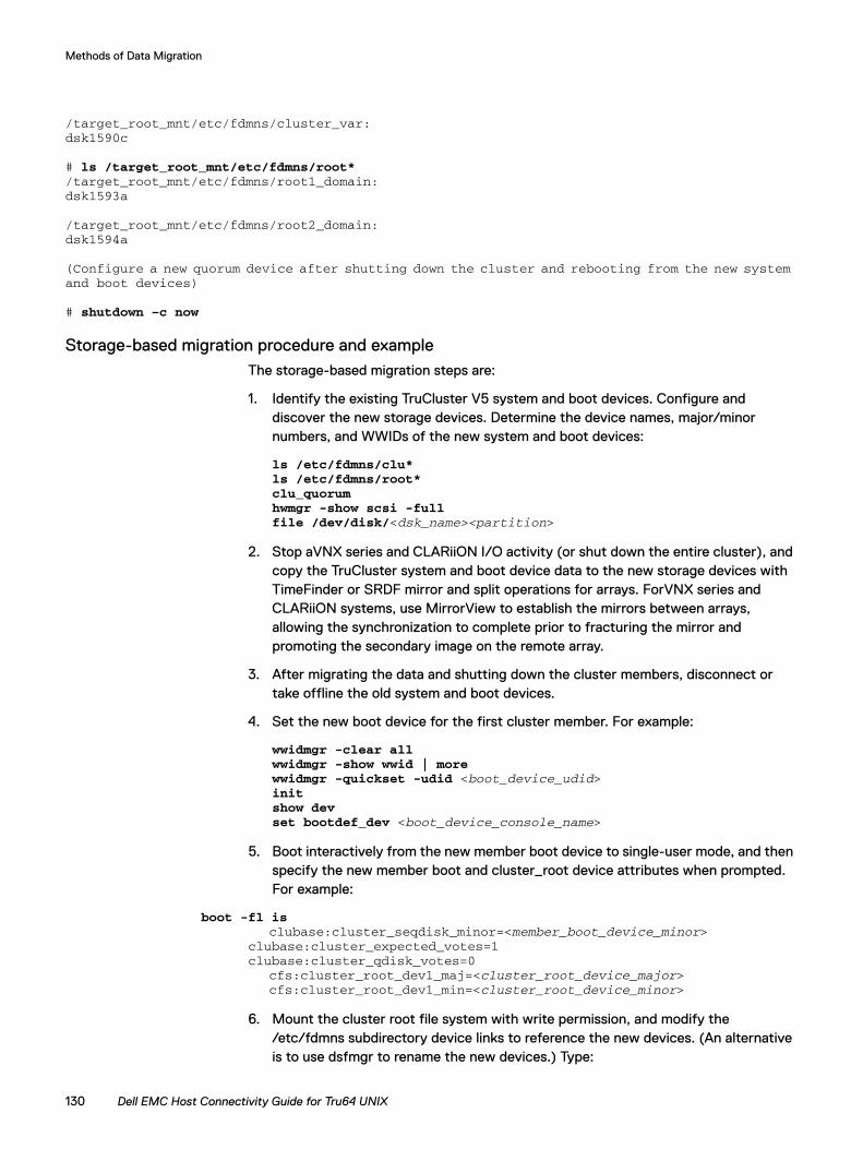
Methods of Data Migration
/target_root_mnt/etc/fdmns/cluster_var:dsk1590c
# ls /target_root_mnt/etc/fdmns/root*/target_root_mnt/etc/fdmns/root1_domain:dsk1593a
/target_root_mnt/etc/fdmns/root2_domain:dsk1594a
(Configure a new quorum device after shutting down the cluster and rebooting from the new systemand boot devices)
# shutdown –c now
Storage-based migration procedure and exampleThe storage-based migration steps are:
1. Identify the existing TruCluster V5 system and boot devices. Configure and discover the new storage devices. Determine the device names, major/minor numbers, and WWIDs of the new system and boot devices:
ls /etc/fdmns/clu*ls /etc/fdmns/root*clu_quorumhwmgr -show scsi -fullfile /dev/disk/<dsk_name><partition>
2. Stop aVNX series and CLARiiON I/O activity (or shut down the entire cluster), and copy the TruCluster system and boot device data to the new storage devices with TimeFinder or SRDF mirror and split operations for arrays. ForVNX series and CLARiiON systems, use MirrorView to establish the mirrors between arrays, allowing the synchronization to complete prior to fracturing the mirror and promoting the secondary image on the remote array.
3. After migrating the data and shutting down the cluster members, disconnect or take offline the old system and boot devices.
4. Set the new boot device for the first cluster member. For example:
wwidmgr -clear allwwidmgr -show wwid | morewwidmgr -quickset -udid <boot_device_udid>initshow devset bootdef_dev <boot_device_console_name>
5. Boot interactively from the new member boot device to single-user mode, and then specify the new member boot and cluster_root device attributes when prompted. For example:
boot -fl isclubase:cluster_seqdisk_minor=<member_boot_device_minor>
clubase:cluster_expected_votes=1clubase:cluster_qdisk_votes=0
cfs:cluster_root_dev1_maj=<cluster_root_device_major>cfs:cluster_root_dev1_min=<cluster_root_device_minor>
6. Mount the cluster root file system with write permission, and modify the /etc/fdmns subdirectory device links to reference the new devices. (An alternative is to use dsfmgr to rename the new devices.) Type:
130 Dell EMC Host Connectivity Guide for Tru64 UNIX
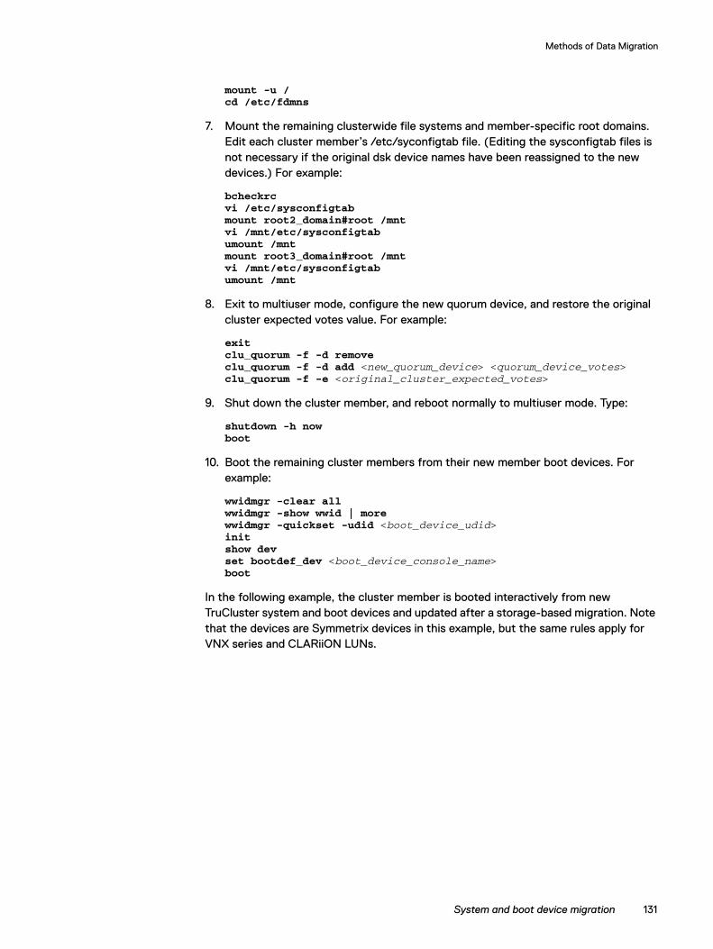
Methods of Data Migration
mount -u /cd /etc/fdmns
7. Mount the remaining clusterwide file systems and member-specific root domains. Edit each cluster member’s /etc/syconfigtab file. (Editing the sysconfigtab files is not necessary if the original dsk device names have been reassigned to the new devices.) For example:
bcheckrcvi /etc/sysconfigtabmount root2_domain#root /mntvi /mnt/etc/sysconfigtabumount /mntmount root3_domain#root /mntvi /mnt/etc/sysconfigtabumount /mnt
8. Exit to multiuser mode, configure the new quorum device, and restore the original cluster expected votes value. For example:
exitclu_quorum -f -d removeclu_quorum -f -d add <new_quorum_device> <quorum_device_votes>clu_quorum -f -e <original_cluster_expected_votes>
9. Shut down the cluster member, and reboot normally to multiuser mode. Type:
shutdown -h nowboot
10. Boot the remaining cluster members from their new member boot devices. For example:
wwidmgr -clear allwwidmgr -show wwid | morewwidmgr -quickset -udid <boot_device_udid>initshow devset bootdef_dev <boot_device_console_name>boot
In the following example, the cluster member is booted interactively from new TruCluster system and boot devices and updated after a storage-based migration. Note that the devices are Symmetrix devices in this example, but the same rules apply for VNX series and CLARiiON LUNs.
System and boot device migration 131
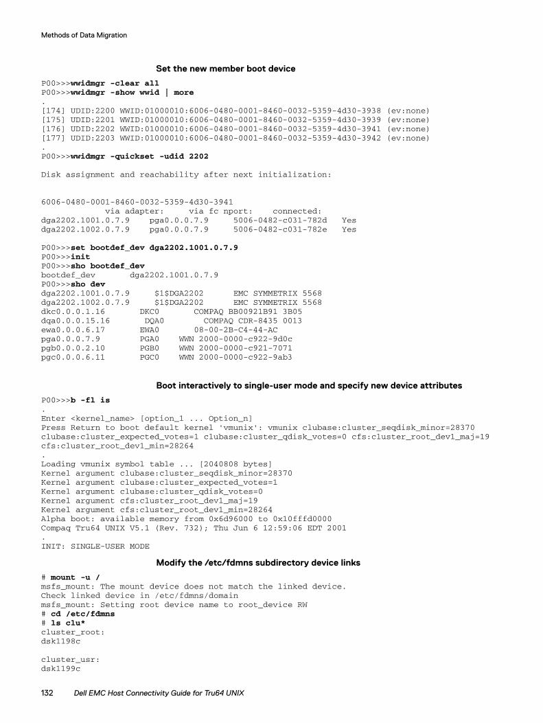
Methods of Data Migration
Set the new member boot device
P00>>>wwidmgr -clear allP00>>>wwidmgr -show wwid | more.[174] UDID:2200 WWID:01000010:6006-0480-0001-8460-0032-5359-4d30-3938 (ev:none)[175] UDID:2201 WWID:01000010:6006-0480-0001-8460-0032-5359-4d30-3939 (ev:none)[176] UDID:2202 WWID:01000010:6006-0480-0001-8460-0032-5359-4d30-3941 (ev:none)[177] UDID:2203 WWID:01000010:6006-0480-0001-8460-0032-5359-4d30-3942 (ev:none).P00>>>wwidmgr -quickset -udid 2202
Disk assignment and reachability after next initialization:
6006-0480-0001-8460-0032-5359-4d30-3941via adapter: via fc nport: connected:
dga2202.1001.0.7.9 pga0.0.0.7.9 5006-0482-c031-782d Yesdga2202.1002.0.7.9 pga0.0.0.7.9 5006-0482-c031-782e Yes
P00>>>set bootdef_dev dga2202.1001.0.7.9P00>>>initP00>>>sho bootdef_devbootdef_dev dga2202.1001.0.7.9P00>>>sho devdga2202.1001.0.7.9 $1$DGA2202 EMC SYMMETRIX 5568dga2202.1002.0.7.9 $1$DGA2202 EMC SYMMETRIX 5568dkc0.0.0.1.16 DKC0 COMPAQ BB00921B91 3B05dqa0.0.0.15.16 DQA0 COMPAQ CDR-8435 0013ewa0.0.0.6.17 EWA0 08-00-2B-C4-44-ACpga0.0.0.7.9 PGA0 WWN 2000-0000-c922-9d0cpgb0.0.0.2.10 PGB0 WWN 2000-0000-c921-7071pgc0.0.0.6.11 PGC0 WWN 2000-0000-c922-9ab3
Boot interactively to single-user mode and specify new device attributes
P00>>>b -fl is.Enter <kernel_name> [option_1 ... Option_n]Press Return to boot default kernel 'vmunix': vmunix clubase:cluster_seqdisk_minor=28370clubase:cluster_expected_votes=1 clubase:cluster_qdisk_votes=0 cfs:cluster_root_dev1_maj=19cfs:cluster_root_dev1_min=28264.Loading vmunix symbol table ... [2040808 bytes]Kernel argument clubase:cluster_seqdisk_minor=28370Kernel argument clubase:cluster_expected_votes=1Kernel argument clubase:cluster_qdisk_votes=0Kernel argument cfs:cluster_root_dev1_maj=19Kernel argument cfs:cluster_root_dev1_min=28264Alpha boot: available memory from 0x6d96000 to 0x10fffd0000Compaq Tru64 UNIX V5.1 (Rev. 732); Thu Jun 6 12:59:06 EDT 2001.INIT: SINGLE-USER MODE
Modify the /etc/fdmns subdirectory device links
# mount -u /msfs_mount: The mount device does not match the linked device.Check linked device in /etc/fdmns/domainmsfs_mount: Setting root device name to root_device RW# cd /etc/fdmns# ls clu*cluster_root:dsk1198c
cluster_usr:dsk1199c
132 Dell EMC Host Connectivity Guide for Tru64 UNIX
Methods of Data Migration
cluster_var:dsk1200c
# ls root*root1_domain:dsk1203a
root2_domain:dsk1204a
# mv cluster_root old_cluster_root# mv cluster_usr old_cluster_usr# mv cluster_var old_cluster_var# mv root1_domain old_root1_domain# mv root2_domain old_root2_domain
# mkdir cluster_root# ln -s /dev/disk/dsk1588c /etc/fdmns/cluster_root# mkdir cluster_usr# ln -s /dev/disk/dsk1589c /etc/fdmns/cluster_usr# mkdir cluster_var# ln -s /dev/disk/dsk1590c /etc/fdmns/cluster_var# mkdir root1_domain# ln -s /dev/disk/dsk1593a /etc/fdmns/root1_domain# mkdir root2_domain# ln -s /dev/disk/dsk1594a /etc/fdmns/root2_domain
# ls clu*cluster_root:dsk1588c
cluster_usr:dsk1589c
cluster_var:dsk1590c
# ls root*root1_domain:dsk1593a
root2_domain:dsk1594a
Update the member /etc/sysconfigtab files
# bcheckrcChecking device naming:Passed.
dsfmgr: NOTE: updating kernel basenames for system at /.Mounting local filesystemsexec: /sbin/mount_advfs -F 0x14000 cluster_root#root /cluster_root#root on / type advfs (rw)exec: /sbin/mount_advfs -F 0x4000 cluster_usr#usr /usrcluster_usr#usr on /usr type advfs (rw)exec: /sbin/mount_advfs -F 0x4000 cluster_var#var /varcluster_var#var on /var type advfs (rw)/proc on /proc type procfs (rw)
# vi /etc/sysconfigtab
vm:swapdevice=/dev/disk/dsk1594b
clubase:
System and boot device migration 133
Methods of Data Migration
cluster_seqdisk_major=19cluster_seqdisk_minor=28370
# mount root1_domain#root /mnt# vi /mnt/etc/sysconfigtab
vm:swapdevice=/dev/disk/dsk1593b
clubase:cluster_seqdisk_major=19cluster_seqdisk_minor=28354
# umount /mnt
Configure the new quorum device, adjust expected votes, and reboot
# exit# clu_quorum -f -d removeCollecting quorum data for Member(s): 1 2
CNX MGR: Delete quorum disk operation completed with quorum.
Quorum disk successfully removed.
# clu_quorum -f -d add dsk1547 1Collecting quorum data for Member(s): 1 2
*** Info ***Disk available but has no label: dsk1547Initializing cnx partition on quorum disk : dsk1547h
Adding the quorum disk could cause a temporary lossof quorum until the disk becomes trusted.Do you want to continue with this operation? [yes]:
There appear to be non-voting member(s) in this cluster. If a non-votingcluster member is unable to access the quorum disk, it may lose quorum.Do you want to continue with this operation? [yes]:
CNX MGR: Add quorum disk operation completed without quorum.CNX MGR: quorum lost, suspending cluster operations.CNX QDISK: Successfully claimed quorum disk, adding 1 vote.CNX MGR: quorum (re)gained, (re)starting cluster operations.
Quorum disk successfully created.
# clu_quorum -f -e 3Collecting quorum data for Member(s): 1 2
CNX MGR: Adjust expected votes operation completed with quorum.
Expected vote successfully adjusted.
# shutdown -h now
P00>>>boot
Boot the remaining cluster members
P00>>>wwidmgr -clear allP00>>>wwidmgr -show wwid | moreP00>>>wwidmgr -quickset -udid 2201P00>>>set bootdef_dev dgc2201.1001.0.3.0P00>>>initP00>>>boot
134 Dell EMC Host Connectivity Guide for Tru64 UNIX
Methods of Data Migration
Related documentation◆ HP Tru64 UNIX Online Documentation and Reference Pages
◆ HP Tru64 UNIX: Enterprise UNIX for HP AlphaServer systems
◆ HP TruCluster Server Online Documentation
◆ HP TruCluster Server Version 5.1A Online Documentation
Related documentation 135