Embed Size (px)
Citation preview
Dell EMC PowerEdge C6400Technical Specifications
Regulatory Model: E43S SeriesRegulatory Type: E43S001

Notes, cautions, and warnings
NOTE: A NOTE indicates important information that helps you make better use of your product.
CAUTION: A CAUTION indicates either potential damage to hardware or loss of data and tells you how to avoid the problem.
WARNING: A WARNING indicates a potential for property damage, personal injury, or death.
© 2017 - 2018 Dell Inc. or its subsidiaries. All rights reserved. Dell, EMC, and other trademarks are trademarks of Dell Inc. or its subsidiaries. Other trademarks may be trademarks of their respective owners.
2019 - 04
Rev. A02
Contents
1 Dell EMC PowerEdge C6400 overview...........................................................................................................4
2 Technical specifications................................................................................................................................. 5Dimensions of the Dell EMC PowerEdge C6400 enclosure......................................................................................... 6Chassis weight....................................................................................................................................................................6Supported operating systems...........................................................................................................................................7PSU specifications............................................................................................................................................................. 7Chassis management board specifications.....................................................................................................................8Drives and storage specifications.....................................................................................................................................8Midplane specifications..................................................................................................................................................... 9Environmental specifications............................................................................................................................................ 9
Standard operating temperature specifications......................................................................................................10Expanded operating temperature specifications ................................................................................................... 19Particulate and gaseous contamination specifications...........................................................................................21Maximum vibration specifications.............................................................................................................................21Maximum shock specifications.................................................................................................................................22Maximum altitude specifications..............................................................................................................................22Fresh Air Operation....................................................................................................................................................22
3 Documentation resources............................................................................................................................ 23
4 Getting help.................................................................................................................................................25Contacting Dell EMC.......................................................................................................................................................25Documentation feedback................................................................................................................................................25Accessing system information by using QRL............................................................................................................... 25
Quick Resource Locator for C6400 and C6420 systems..................................................................................... 26Receiving automated support with SupportAssist ..................................................................................................... 26Recycling or End-of-Life service information............................................................................................................... 26
Contents 3

Dell EMC PowerEdge C6400 overviewThe PowerEdge C6400 is an ultra-dense 2U enclosure that can support up to four independent two-socket (2S) sleds. The PowerEdge C6400 enclosure supports the following drive configurations:
• up to 24 x 2.5-inch SAS or SATA drives
• up to 8 x 2.5-inch NVMe drives, with 16 x 2.5-inch SAS or SATA drives
• up to 12 x 3.5-inch SAS or SATA drives
• diskless no backplane
1
4 Dell EMC PowerEdge C6400 overview
Technical specifications
The technical and environmental specifications of your system are outlined in this section.
Topics:
• Dimensions of the Dell EMC PowerEdge C6400 enclosure
• Chassis weight
• Supported operating systems
• PSU specifications
• Chassis management board specifications
• Drives and storage specifications
• Midplane specifications
• Environmental specifications
2
Technical specifications 5
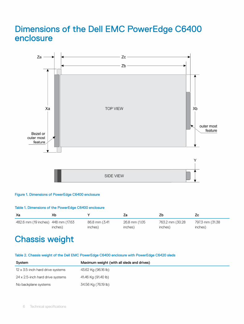
Dimensions of the Dell EMC PowerEdge C6400 enclosure
Figure 1. Dimensions of PowerEdge C6400 enclosure
Table 1. Dimensions of the PowerEdge C6400 enclosure
Xa Xb Y Za Zb Zc
482.6 mm (19 inches) 448 mm (17.63 inches)
86.8 mm (3.41 inches)
26.8 mm (1.05 inches)
763.2 mm (30.28 inches)
797.3 mm (31.38 inches)
Chassis weight
Table 2. Chassis weight of the Dell EMC PowerEdge C6400 enclosure with PowerEdge C6420 sleds
System Maximum weight (with all sleds and drives)
12 x 3.5-inch hard drive systems 43.62 Kg (96.16 lb)
24 x 2.5-inch hard drive systems 41.46 Kg (91.40 lb)
No backplane systems 34.56 Kg (76.19 lb)
6 Technical specifications
Supported operating systemsThe Dell EMC PowerEdge C6400 supports the following operating systems:
• Canonical Ubuntu LTS
• Citrix XenServer
• Microsoft Windows Server with Hyper-V
• Red Hat Enterprise Linux
• SUSE Linux Enterprise Server
• VMware ESXi
NOTE: For more information about the specific versions and additions, see https://www.dell.com/support/home/drivers/supportedos/poweredge-c6400
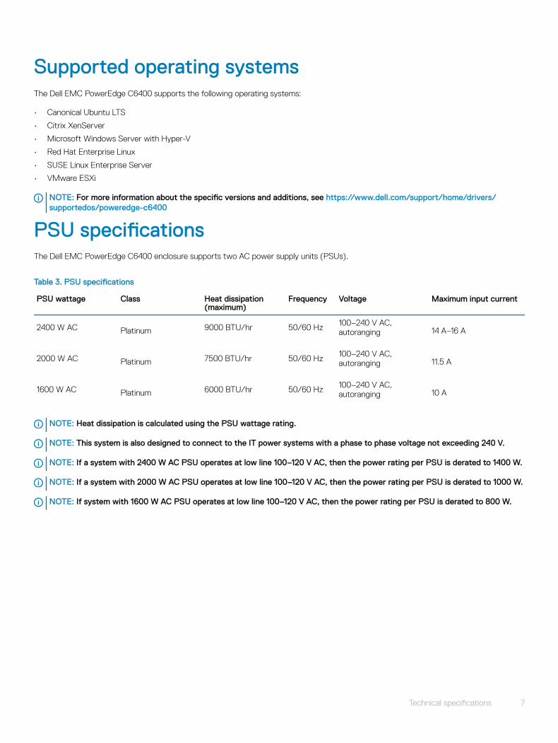
PSU specificationsThe Dell EMC PowerEdge C6400 enclosure supports two AC power supply units (PSUs).
Table 3. PSU specifications
PSU wattage Class Heat dissipation (maximum)
Frequency Voltage Maximum input current
2400 W AC Platinum 9000 BTU/hr 50/60 Hz 100–240 V AC, autoranging 14 A–16 A
2000 W AC Platinum 7500 BTU/hr 50/60 Hz 100–240 V AC, autoranging 11.5 A
1600 W AC Platinum 6000 BTU/hr 50/60 Hz 100–240 V AC, autoranging 10 A
NOTE: Heat dissipation is calculated using the PSU wattage rating.
NOTE: This system is also designed to connect to the IT power systems with a phase to phase voltage not exceeding 240 V.
NOTE: If a system with 2400 W AC PSU operates at low line 100–120 V AC, then the power rating per PSU is derated to 1400 W.
NOTE: If a system with 2000 W AC PSU operates at low line 100–120 V AC, then the power rating per PSU is derated to 1000 W.
NOTE: If system with 1600 W AC PSU operates at low line 100–120 V AC, then the power rating per PSU is derated to 800 W.
Technical specifications 7
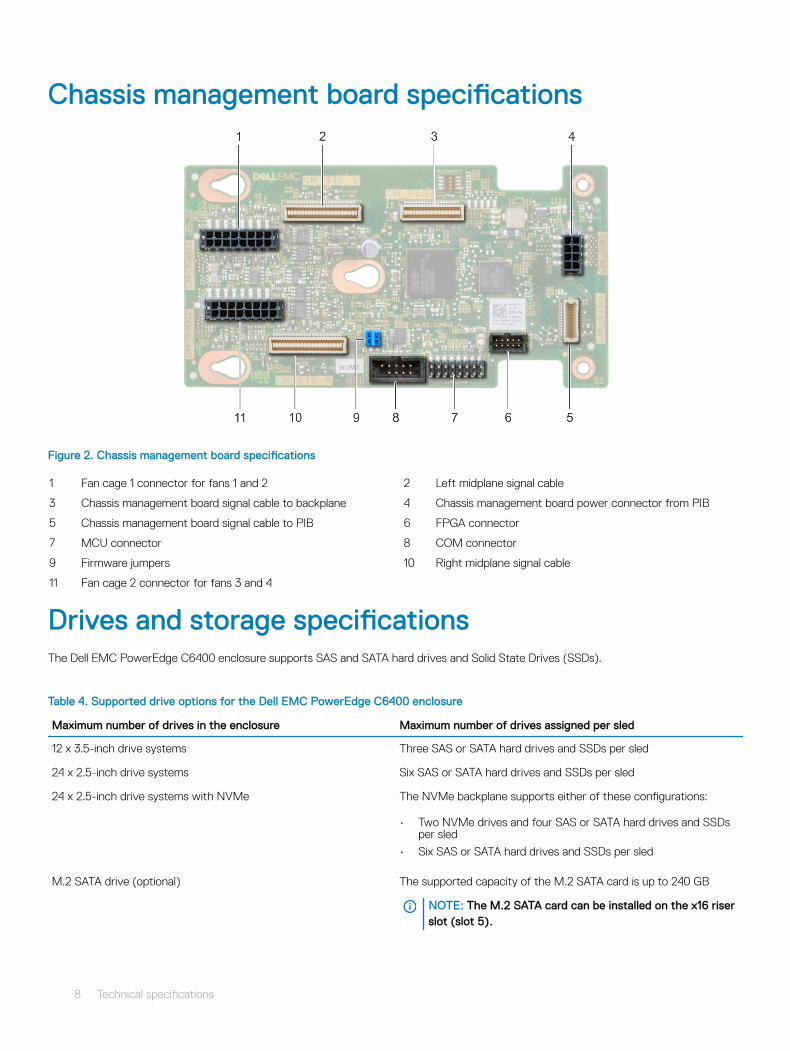
Chassis management board specifications
Figure 2. Chassis management board specifications
1 Fan cage 1 connector for fans 1 and 2 2 Left midplane signal cable
3 Chassis management board signal cable to backplane 4 Chassis management board power connector from PIB
5 Chassis management board signal cable to PIB 6 FPGA connector
7 MCU connector 8 COM connector
9 Firmware jumpers 10 Right midplane signal cable
11 Fan cage 2 connector for fans 3 and 4
Drives and storage specificationsThe Dell EMC PowerEdge C6400 enclosure supports SAS and SATA hard drives and Solid State Drives (SSDs).
Table 4. Supported drive options for the Dell EMC PowerEdge C6400 enclosure
Maximum number of drives in the enclosure Maximum number of drives assigned per sled
12 x 3.5-inch drive systems Three SAS or SATA hard drives and SSDs per sled
24 x 2.5-inch drive systems Six SAS or SATA hard drives and SSDs per sled
24 x 2.5-inch drive systems with NVMe The NVMe backplane supports either of these configurations:
• Two NVMe drives and four SAS or SATA hard drives and SSDs per sled
• Six SAS or SATA hard drives and SSDs per sled
M.2 SATA drive (optional) The supported capacity of the M.2 SATA card is up to 240 GB
NOTE: The M.2 SATA card can be installed on the x16 riser slot (slot 5).
8 Technical specifications
Maximum number of drives in the enclosure Maximum number of drives assigned per sled
Micro-SD card (optional) for boot (up to 64 GB) One on each PCIe riser of each sled
Table 5. Supported RAID options with M.2 SATA drives
Options Single M.2 SATA drive without RAID Dual M.2 SATA drives with hardware RAID
Hardware RAID No Yes
RAID Mode N/A RAID 1
Number of drives supported 1 2
Supported CPUs CPU 1 CPU 1 and CPU 2
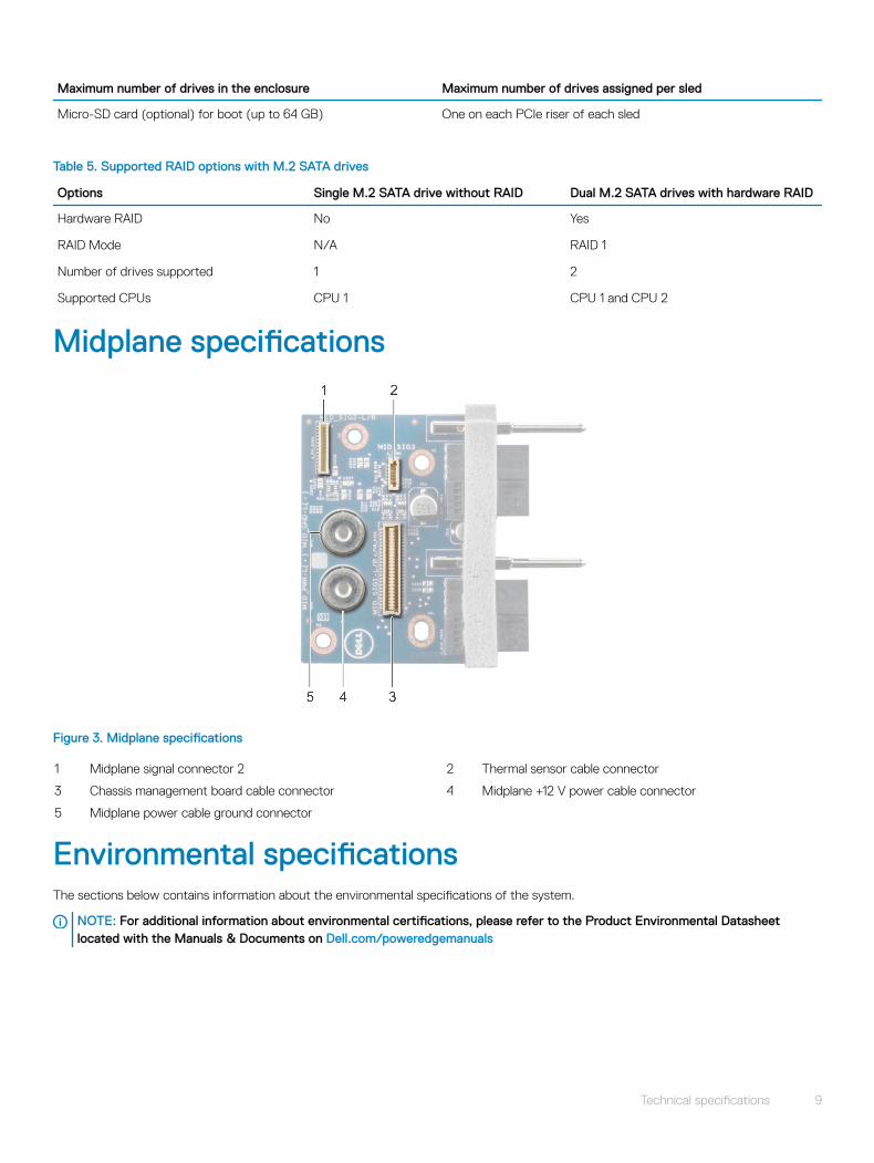
Midplane specifications
Figure 3. Midplane specifications
1 Midplane signal connector 2 2 Thermal sensor cable connector
3 Chassis management board cable connector 4 Midplane +12 V power cable connector
5 Midplane power cable ground connector
Environmental specificationsThe sections below contains information about the environmental specifications of the system.
NOTE: For additional information about environmental certifications, please refer to the Product Environmental Datasheet located with the Manuals & Documents on Dell.com/poweredgemanuals
Technical specifications 9
Standard operating temperature specificationsNOTE:
1 Not available: Indicates that the configuration is not offered by Dell EMC.
2 Not supported: Indicates that the configuration is not thermally supported.
NOTE: All components including the DIMMs, communication cards, M.2 SATA, and PERC cards can be supported with sufficient thermal margin if the ambient temperature is equal to or below to the maximum continuous operating temperature listed in these tables except for the Mellanox DP LP card and Intel Rush Creek card.
Table 6. Standard operating temperature specifications
Standard operating temperature Specifications
Temperature ranges (for altitude less than 950 m or 3117 ft) 10°C–35°C (50°F–95°F) with no direct sunlight on the equipment.
NOTE: Some configurations require a lower ambient temperature. For more information, see the following tables.
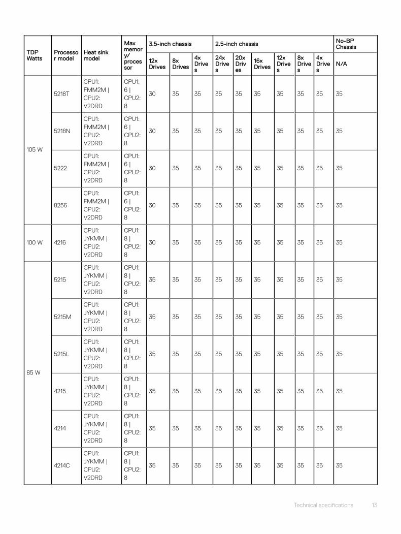
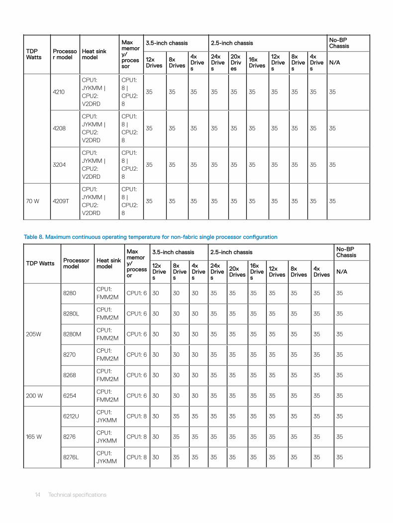
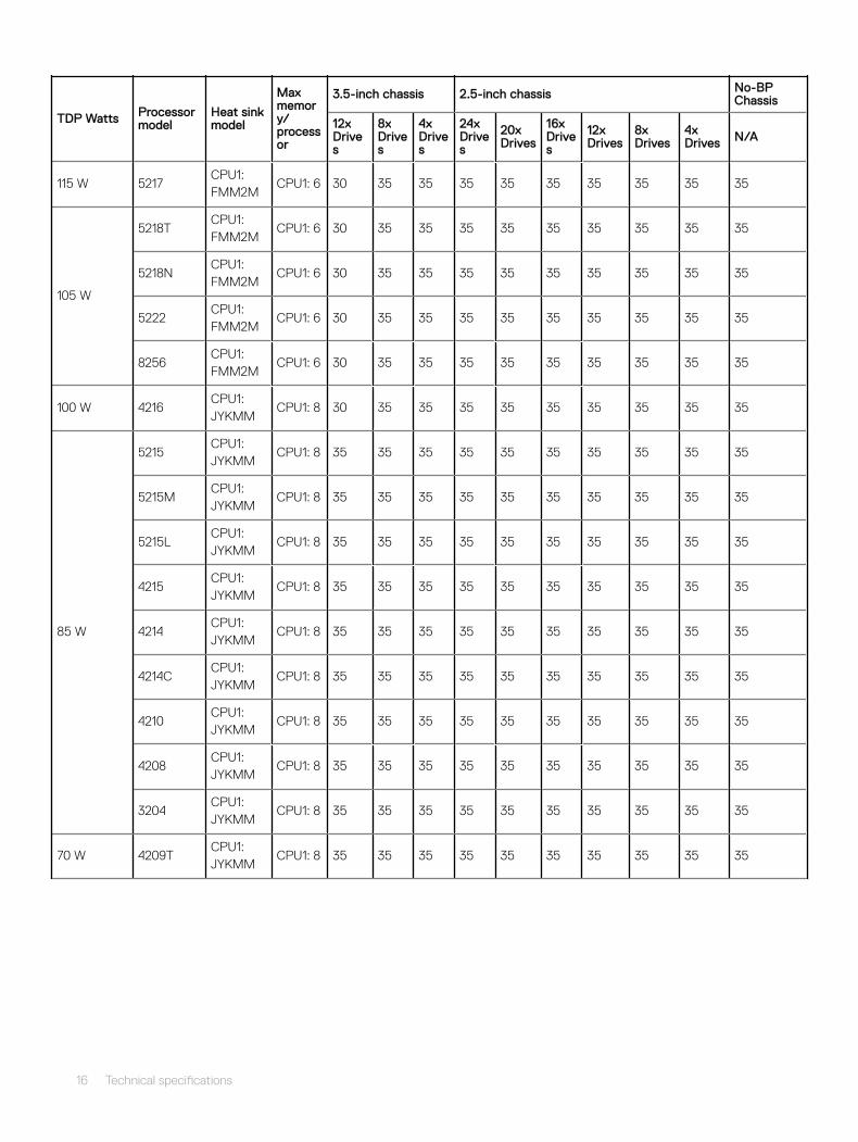
Table 7. Maximum continuous operating temperature for nonfabric dual processor configuration
TDP Watts
Processor model
Heat sink model
Max memory/processor
3.5-inch chassis 2.5-inch chassis No-BP Chassis
12x Drives
8x Drives
4x Drives
24x Drives
20x Drives
16x Drives
12x Drives
8x Drives
4x Drives
N/A
205 W
8280
CPU1: FMM2M | CPU2: V2DRD
CPU1: 6 | CPU2: 8
Not Supported (2°C)
Not Supported (10°C)
Not Supported (11°C)
Not Supported(19°C)
20 21 21 21 21 30
8280L
CPU1: FMM2M | CPU2: V2DRD
CPU1: 6 | CPU2: 8
20 21 21 21 21 30
8280M
CPU1: FMM2M | CPU2: V2DRD
CPU1: 6 | CPU2: 8
20 21 21 21 21 30
8270
CPU1: FMM2M | CPU2: V2DRD
CPU1: 6 | CPU2: 8
20 21 21 21 21 30
8268
CPU1: FMM2M | CPU2: V2DRD
CPU1: 6 | CPU2: 8
20 21 21 21 21 30
200 W 6254CPU1: FMM2M |
CPU1: 6 |
Not Suppor
Not Suppo
Not Supp
20 21 22 22 22 22 30
10 Technical specifications
TDP Watts
Processor model
Heat sink model
Max memory/processor
3.5-inch chassis 2.5-inch chassis No-BP Chassis
12x Drives
8x Drives
4x Drives
24x Drives
20x Drives
16x Drives
12x Drives
8x Drives
4x Drives
N/A
CPU2: V2DRD
CPU2: 8
ted(6°C)
rted(14°C)
orted(15°C)
165 W
8276
CPU1: JYKMM | CPU2: V2DRD
CPU1: 8 | CPU2: 8
Not Supported(11°C)
Not Supported(18°C)
Not Supported(19°C)
30 30 30 30 30 35 35
8276L
CPU1: JYKMM | CPU2: V2DRD
CPU1: 8 | CPU2: 8
30 30 30 30 30 35 35
8276M
CPU1: JYKMM | CPU2: V2DRD
CPU1: 8 | CPU2: 8
30 30 30 30 30 35 35
8260
CPU1: JYKMM | CPU2: V2DRD
CPU1: 8 | CPU2: 8
30 30 30 30 30 35 35
8260L
CPU1: JYKMM | CPU2: V2DRD
CPU1: 8 | CPU2: 8
30 30 30 30 30 35 35
8260M
CPU1: JYKMM | CPU2: V2DRD
CPU1: 8 | CPU2: 8
30 30 30 30 30 35 35
8260C
CPU1: JYKMM | CPU2: V2DRD
CPU1: 8 | CPU2: 8
30 30 30 30 30 35 35
150 W
6252
CPU1: JYKMM | CPU2: V2DRD
CPU1: 8 | CPU2: 8
Not Supported(14°C)
21 23 30 30 30 30 30 35 35
6248
CPU1: JYKMM | CPU2: V2DRD
CPU1: 8 | CPU2: 8
21 23 30 30 30 30 30 35 35
6240
CPU1: JYKMM | CPU2: V2DRD
CPU1: 8 | CPU2: 8
21 23 30 30 30 30 30 35 35
Technical specifications 11

TDP Watts
Processor model
Heat sink model
Max memory/processor
3.5-inch chassis 2.5-inch chassis No-BP Chassis
12x Drives
8x Drives
4x Drives
24x Drives
20x Drives
16x Drives
12x Drives
8x Drives
4x Drives
N/A
6242
CPU1: JYKMM | CPU2: V2DRD
CPU1: 8 | CPU2: 8
21 23 30 30 30 30 30 35 35
6244
CPU1: FMM2M | CPU2: V2DRD
CPU1: 6 | CPU2: 8
21 23 30 30 30 30 30 35 35
6240C
CPU1: FMM2M | CPU2: V2DRD
CPU1: 6 | CPU2: 8
21 23 30 30 30 30 30 35 35
125 W
6230
CPU1: JYKMM | CPU2: V2DRD
CPU1: 8 | CPU2: 8
25 30 30 30 30 35 35 35 35 35
5220
CPU1: JYKMM | CPU2: V2DRD
CPU1: 8 | CPU2: 8
25 30 30 30 30 35 35 35 35 35
5218
CPU1: JYKMM | CPU2: V2DRD
CPU1: 8 | CPU2: 8
25 30 30 30 30 35 35 35 35 35
5218B
CPU1: JYKMM | CPU2: V2DRD
CPU1: 8 | CPU2: 8
25 30 30 30 30 35 35 35 35 35
8253
CPU1: JYKMM | CPU2: V2DRD
CPU1: 8 | CPU2: 8
25 30 30 30 30 35 35 35 35 35
6238T
CPU1: JYKMM | CPU2: V2DRD
CPU1: 8 | CPU2: 8
25 30 30 30 30 35 35 35 35 35
6230N
CPU1: JYKMM | CPU2: V2DRD
CPU1: 8 | CPU2: 8
25 30 30 30 30 35 35 35 35 35
115 W 5217
CPU1: FMM2M | CPU2: V2DRD
CPU1: 6 | CPU2: 8
25 30 30 30 30 35 35 35 35 35
12 Technical specifications
TDP Watts
Processor model
Heat sink model
Max memory/processor
3.5-inch chassis 2.5-inch chassis No-BP Chassis
12x Drives
8x Drives
4x Drives
24x Drives
20x Drives
16x Drives
12x Drives
8x Drives
4x Drives
N/A
105 W
5218T
CPU1: FMM2M | CPU2: V2DRD
CPU1: 6 | CPU2: 8
30 35 35 35 35 35 35 35 35 35
5218N
CPU1: FMM2M | CPU2: V2DRD
CPU1: 6 | CPU2: 8
30 35 35 35 35 35 35 35 35 35
5222
CPU1: FMM2M | CPU2: V2DRD
CPU1: 6 | CPU2: 8
30 35 35 35 35 35 35 35 35 35
8256
CPU1: FMM2M | CPU2: V2DRD
CPU1: 6 | CPU2: 8
30 35 35 35 35 35 35 35 35 35
100 W 4216
CPU1: JYKMM | CPU2: V2DRD
CPU1: 8 | CPU2: 8
30 35 35 35 35 35 35 35 35 35
85 W
5215
CPU1: JYKMM | CPU2: V2DRD
CPU1: 8 | CPU2: 8
35 35 35 35 35 35 35 35 35 35
5215M
CPU1: JYKMM | CPU2: V2DRD
CPU1: 8 | CPU2: 8
35 35 35 35 35 35 35 35 35 35
5215L
CPU1: JYKMM | CPU2: V2DRD
CPU1: 8 | CPU2: 8
35 35 35 35 35 35 35 35 35 35
4215
CPU1: JYKMM | CPU2: V2DRD
CPU1: 8 | CPU2: 8
35 35 35 35 35 35 35 35 35 35
4214
CPU1: JYKMM | CPU2: V2DRD
CPU1: 8 | CPU2: 8
35 35 35 35 35 35 35 35 35 35
4214C
CPU1: JYKMM | CPU2: V2DRD
CPU1: 8 | CPU2: 8
35 35 35 35 35 35 35 35 35 35
Technical specifications 13
TDP Watts
Processor model
Heat sink model
Max memory/processor
3.5-inch chassis 2.5-inch chassis No-BP Chassis
12x Drives
8x Drives
4x Drives
24x Drives
20x Drives
16x Drives
12x Drives
8x Drives
4x Drives
N/A
4210
CPU1: JYKMM | CPU2: V2DRD
CPU1: 8 | CPU2: 8
35 35 35 35 35 35 35 35 35 35
4208
CPU1: JYKMM | CPU2: V2DRD
CPU1: 8 | CPU2: 8
35 35 35 35 35 35 35 35 35 35
3204
CPU1: JYKMM | CPU2: V2DRD
CPU1: 8 | CPU2: 8
35 35 35 35 35 35 35 35 35 35
70 W 4209T
CPU1: JYKMM | CPU2: V2DRD
CPU1: 8 | CPU2: 8
35 35 35 35 35 35 35 35 35 35
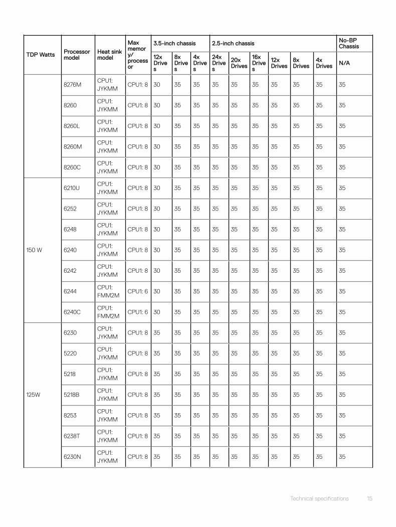
Table 8. Maximum continuous operating temperature for non-fabric single processor configuration
TDP Watts Processor model
Heat sink model
Max memory/processor
3.5-inch chassis 2.5-inch chassis No-BP Chassis
12x Drives
8x Drives
4x Drives
24x Drives
20x Drives
16x Drives
12x Drives
8x Drives
4x Drives N/A
205W
8280CPU1: FMM2M
CPU1: 6 30 30 30 35 35 35 35 35 35 35
8280LCPU1: FMM2M
CPU1: 6 30 30 30 35 35 35 35 35 35 35
8280MCPU1: FMM2M
CPU1: 6 30 30 30 35 35 35 35 35 35 35
8270CPU1: FMM2M
CPU1: 6 30 30 30 35 35 35 35 35 35 35
8268CPU1: FMM2M
CPU1: 6 30 30 30 35 35 35 35 35 35 35
200 W 6254CPU1: FMM2M
CPU1: 6 30 30 30 35 35 35 35 35 35 35
165 W
6212UCPU1: JYKMM
CPU1: 8 30 35 35 35 35 35 35 35 35 35
8276CPU1: JYKMM
CPU1: 8 30 35 35 35 35 35 35 35 35 35
8276LCPU1: JYKMM
CPU1: 8 30 35 35 35 35 35 35 35 35 35
14 Technical specifications
TDP Watts Processor model
Heat sink model
Max memory/processor
3.5-inch chassis 2.5-inch chassis No-BP Chassis
12x Drives
8x Drives
4x Drives
24x Drives
20x Drives
16x Drives
12x Drives
8x Drives
4x Drives N/A
8276MCPU1: JYKMM
CPU1: 8 30 35 35 35 35 35 35 35 35 35
8260CPU1: JYKMM
CPU1: 8 30 35 35 35 35 35 35 35 35 35
8260LCPU1: JYKMM
CPU1: 8 30 35 35 35 35 35 35 35 35 35
8260MCPU1: JYKMM
CPU1: 8 30 35 35 35 35 35 35 35 35 35
8260CCPU1: JYKMM
CPU1: 8 30 35 35 35 35 35 35 35 35 35
150 W
6210UCPU1: JYKMM
CPU1: 8 30 35 35 35 35 35 35 35 35 35
6252CPU1: JYKMM
CPU1: 8 30 35 35 35 35 35 35 35 35 35
6248CPU1: JYKMM
CPU1: 8 30 35 35 35 35 35 35 35 35 35
6240CPU1: JYKMM
CPU1: 8 30 35 35 35 35 35 35 35 35 35
6242CPU1: JYKMM
CPU1: 8 30 35 35 35 35 35 35 35 35 35
6244CPU1: FMM2M
CPU1: 6 30 35 35 35 35 35 35 35 35 35
6240CCPU1: FMM2M
CPU1: 6 30 35 35 35 35 35 35 35 35 35
125W
6230CPU1: JYKMM
CPU1: 8 35 35 35 35 35 35 35 35 35 35
5220CPU1: JYKMM
CPU1: 8 35 35 35 35 35 35 35 35 35 35
5218CPU1: JYKMM
CPU1: 8 35 35 35 35 35 35 35 35 35 35
5218BCPU1: JYKMM
CPU1: 8 35 35 35 35 35 35 35 35 35 35
8253CPU1: JYKMM
CPU1: 8 35 35 35 35 35 35 35 35 35 35
6238TCPU1: JYKMM
CPU1: 8 35 35 35 35 35 35 35 35 35 35
6230NCPU1: JYKMM
CPU1: 8 35 35 35 35 35 35 35 35 35 35
Technical specifications 15
TDP Watts Processor model
Heat sink model
Max memory/processor
3.5-inch chassis 2.5-inch chassis No-BP Chassis
12x Drives
8x Drives
4x Drives
24x Drives
20x Drives
16x Drives
12x Drives
8x Drives
4x Drives N/A
115 W 5217CPU1: FMM2M
CPU1: 6 30 35 35 35 35 35 35 35 35 35
105 W
5218TCPU1: FMM2M
CPU1: 6 30 35 35 35 35 35 35 35 35 35
5218NCPU1: FMM2M
CPU1: 6 30 35 35 35 35 35 35 35 35 35
5222CPU1: FMM2M
CPU1: 6 30 35 35 35 35 35 35 35 35 35
8256CPU1: FMM2M
CPU1: 6 30 35 35 35 35 35 35 35 35 35
100 W 4216CPU1: JYKMM
CPU1: 8 30 35 35 35 35 35 35 35 35 35
85 W
5215CPU1: JYKMM
CPU1: 8 35 35 35 35 35 35 35 35 35 35
5215MCPU1: JYKMM
CPU1: 8 35 35 35 35 35 35 35 35 35 35
5215LCPU1: JYKMM
CPU1: 8 35 35 35 35 35 35 35 35 35 35
4215CPU1: JYKMM
CPU1: 8 35 35 35 35 35 35 35 35 35 35
4214CPU1: JYKMM
CPU1: 8 35 35 35 35 35 35 35 35 35 35
4214CCPU1: JYKMM
CPU1: 8 35 35 35 35 35 35 35 35 35 35
4210CPU1: JYKMM
CPU1: 8 35 35 35 35 35 35 35 35 35 35
4208CPU1: JYKMM
CPU1: 8 35 35 35 35 35 35 35 35 35 35
3204CPU1: JYKMM
CPU1: 8 35 35 35 35 35 35 35 35 35 35
70 W 4209TCPU1: JYKMM
CPU1: 8 35 35 35 35 35 35 35 35 35 35
16 Technical specifications
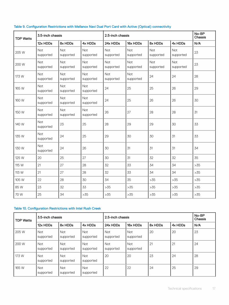
Table 9. Configuration Restrictions with Mellanox Navi Dual Port Card with Active (Optical) connectivity
TDP Watts3.5-inch chassis 2.5-inch chassis No-BP
Chassis
12x HDDs 8x HDDs 4x HDDs 24x HDDs 16x HDDs 8x HDDs 4x HDDs N/A
205 WNot supported
Not supported
Not supported
Not supported
Not supported
Not supported
Not supported
23
200 WNot supported
Not supported
Not supported
Not supported
Not supported
Not supported
Not supported
23
173 WNot supported
Not supported
Not supported
Not supported
Not supported
24 24 28
165 WNot supported
Not supported
Not supported
24 25 25 26 29
160 WNot supported
Not supported
Not supported
24 25 26 26 30
150 WNot supported
Not supported
Not supported
26 27 28 28 31
140 WNot supported
23 25 28 29 29 30 33
135 WNot supported
24 25 29 30 30 31 33
130 WNot supported
24 26 30 31 31 31 34
125 W 20 25 27 30 31 32 32 35
115 W 21 27 28 32 33 34 34 >35
113 W 21 27 28 32 33 34 34 >35
105 W 22 28 30 34 35 >35 >35 >35
85 W 23 32 33 >35 >35 >35 >35 >35
70 W 25 34 >35 >35 >35 >35 >35 >35
Table 10. Configuration Restrictions with Intel Rush Creek
TDP Watts3.5-inch chassis 2.5-inch chassis No-BP
Chassis
12x HDDs 8x HDDs 4x HDDs 24x HDDs 16x HDDs 8x HDDs 4x HDDs N/A
205 W Not supported
Not supported
Not supported
Not supported
Not supported
20 20 23
200 W Not supported
Not supported
Not supported
Not supported
Not supported
21 21 24
173 W Not supported
Not supported
Not supported
20 20 23 24 28
165 W Not supported
Not supported
Not supported
22 22 24 25 29
Technical specifications 17
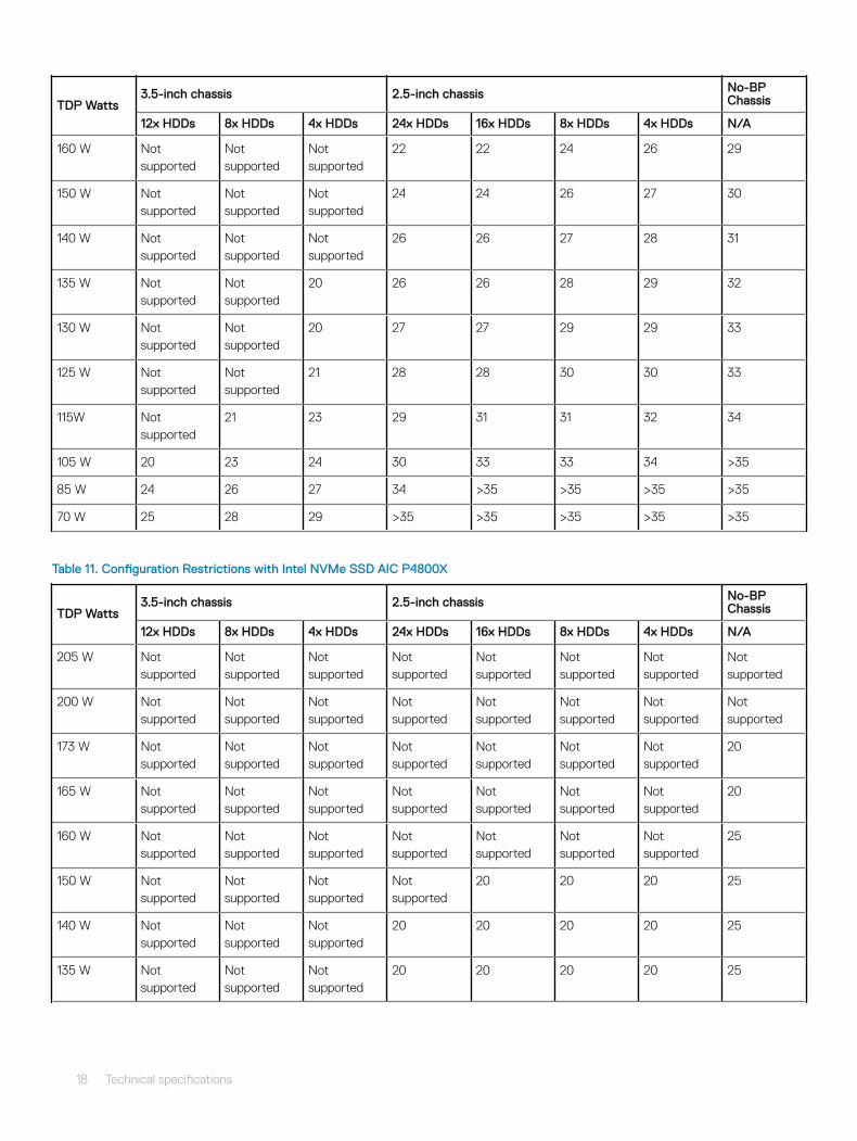
TDP Watts3.5-inch chassis 2.5-inch chassis No-BP
Chassis
12x HDDs 8x HDDs 4x HDDs 24x HDDs 16x HDDs 8x HDDs 4x HDDs N/A
160 W Not supported
Not supported
Not supported
22 22 24 26 29
150 W Not supported
Not supported
Not supported
24 24 26 27 30
140 W Not supported
Not supported
Not supported
26 26 27 28 31
135 W Not supported
Not supported
20 26 26 28 29 32
130 W Not supported
Not supported
20 27 27 29 29 33
125 W Not supported
Not supported
21 28 28 30 30 33
115W Not supported
21 23 29 31 31 32 34
105 W 20 23 24 30 33 33 34 >35
85 W 24 26 27 34 >35 >35 >35 >35
70 W 25 28 29 >35 >35 >35 >35 >35
Table 11. Configuration Restrictions with Intel NVMe SSD AIC P4800X
TDP Watts3.5-inch chassis 2.5-inch chassis No-BP
Chassis
12x HDDs 8x HDDs 4x HDDs 24x HDDs 16x HDDs 8x HDDs 4x HDDs N/A
205 W Not supported
Not supported
Not supported
Not supported
Not supported
Not supported
Not supported
Not supported
200 W Not supported
Not supported
Not supported
Not supported
Not supported
Not supported
Not supported
Not supported
173 W Not supported
Not supported
Not supported
Not supported
Not supported
Not supported
Not supported
20
165 W Not supported
Not supported
Not supported
Not supported
Not supported
Not supported
Not supported
20
160 W Not supported
Not supported
Not supported
Not supported
Not supported
Not supported
Not supported
25
150 W Not supported
Not supported
Not supported
Not supported
20 20 20 25
140 W Not supported
Not supported
Not supported
20 20 20 20 25
135 W Not supported
Not supported
Not supported
20 20 20 20 25
18 Technical specifications
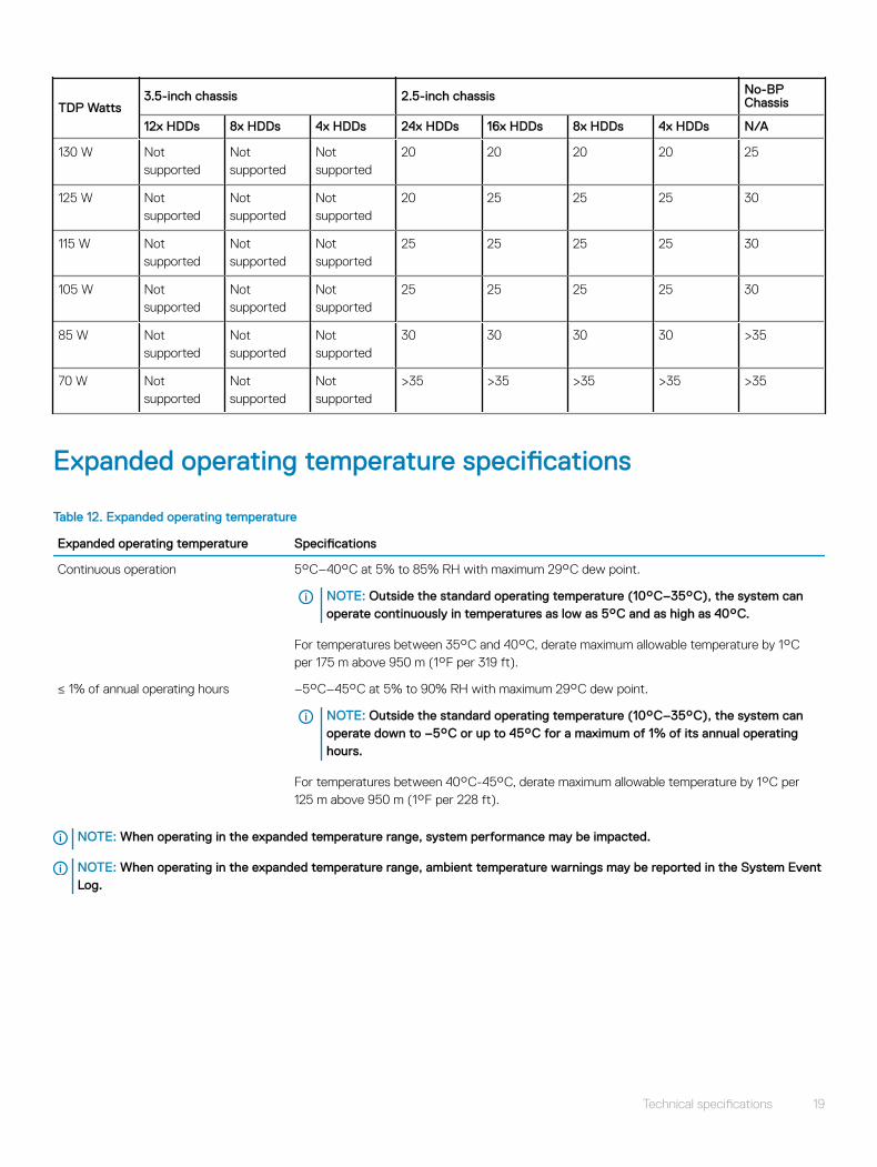
TDP Watts3.5-inch chassis 2.5-inch chassis No-BP
Chassis
12x HDDs 8x HDDs 4x HDDs 24x HDDs 16x HDDs 8x HDDs 4x HDDs N/A
130 W Not supported
Not supported
Not supported
20 20 20 20 25
125 W Not supported
Not supported
Not supported
20 25 25 25 30
115 W Not supported
Not supported
Not supported
25 25 25 25 30
105 W Not supported
Not supported
Not supported
25 25 25 25 30
85 W Not supported
Not supported
Not supported
30 30 30 30 >35
70 W Not supported
Not supported
Not supported
>35 >35 >35 >35 >35
Expanded operating temperature specifications
Table 12. Expanded operating temperature
Expanded operating temperature Specifications
Continuous operation 5°C–40°C at 5% to 85% RH with maximum 29°C dew point.
NOTE: Outside the standard operating temperature (10°C–35°C), the system can operate continuously in temperatures as low as 5°C and as high as 40°C.
For temperatures between 35°C and 40°C, derate maximum allowable temperature by 1°C per 175 m above 950 m (1°F per 319 ft).
≤ 1% of annual operating hours –5°C–45°C at 5% to 90% RH with maximum 29°C dew point.
NOTE: Outside the standard operating temperature (10°C–35°C), the system can operate down to –5°C or up to 45°C for a maximum of 1% of its annual operating hours.
For temperatures between 40°C-45°C, derate maximum allowable temperature by 1°C per 125 m above 950 m (1°F per 228 ft).
NOTE: When operating in the expanded temperature range, system performance may be impacted.
NOTE: When operating in the expanded temperature range, ambient temperature warnings may be reported in the System Event Log.
Technical specifications 19

Operating temperature derating specifications
Table 13. Operating temperature
Operating temperature derating Specifications
< 35°C (95°F) Maximum temperature is reduced by 1°C/300 m (1°F/547 ft) above 950 meters (3,117 ft).
35°C–40°C (95°F–104°F) Maximum temperature is reduced by 1°C/175 m (1°F/319 ft) above 950 meters (3,117 ft).
> 45°C (113°F) Maximum temperature is reduced by 1°C/125 m (1°F/228 ft) above 950 meters (3,117 ft).
Relative humidity specifications
Table 14. Relative humidity specifications
Relative humidity Specifications
Storage 5% to 95% RH with 33°C (91°F) maximum dew point. Atmosphere must be noncondensing always.
Operating 10% to 80% relative humidity with 29°C (84.2°F) maximum dew point.
Temperature specifications
Table 15. Temperature specifications
Temperature Specifications
Storage –40°C–65°C (–40°F to 149°F)
Continuous operation (for altitude less than 950 m or 3117 ft) 10°C–35°C (50°F to 95°F) with no direct sunlight on the equipment.
Fresh air For information about fresh air, see Expanded Operating Temperature section.
Maximum temperature gradient (operating and storage) 20°C/h (68°F/h)
NOTE: Some configurations require a lower ambient temperature for more information, see the Standard operating temperature specifications.
20 Technical specifications
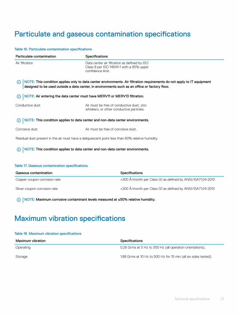
Particulate and gaseous contamination specifications
Table 16. Particulate contamination specifications
Particulate contamination Specifications
Air filtration Data center air filtration as defined by ISO Class 8 per ISO 14644-1 with a 95% upper confidence limit.
NOTE: This condition applies only to data center environments. Air filtration requirements do not apply to IT equipment designed to be used outside a data center, in environments such as an office or factory floor.
NOTE: Air entering the data center must have MERV11 or MERV13 filtration.
Conductive dust Air must be free of conductive dust, zinc whiskers, or other conductive particles.
NOTE: This condition applies to data center and non-data center environments.
Corrosive dust Air must be free of corrosive dust.
Residual dust present in the air must have a deliquescent point less than 60% relative humidity.
NOTE: This condition applies to data center and non-data center environments.
Table 17. Gaseous contamination specifications
Gaseous contamination Specifications
Copper coupon corrosion rate <300 Å/month per Class G1 as defined by ANSI/ISA71.04-2013
Silver coupon corrosion rate <200 Å/month per Class G1 as defined by ANSI/ISA71.04-2013
NOTE: Maximum corrosive contaminant levels measured at ≤50% relative humidity.
Maximum vibration specifications
Table 18. Maximum vibration specifications
Maximum vibration Specifications
Operating 0.26 Grms at 5 Hz to 350 Hz (all operation orientations).
Storage 1.88 Grms at 10 Hz to 500 Hz for 15 min (all six sides tested).
Technical specifications 21
Maximum shock specifications
Table 19. Maximum shock specifications
Maximum shock Specifications
Operating 24 executed shock pulses 6 G in the positive and negative x, y, z axis for up to 11 ms (four pulses on each side of the system).
Storage Six consecutively executed shock pulses of 71 G in the positive and negative x, y, z axes for up to 2 ms (one pulse on each side of the system).
Maximum altitude specifications
Table 20. Maximum altitude specifications
Maximum altitude Specifications
Operating 3048 m (10,000 ft)
Storage 12,000 m (39,370 ft)
Fresh Air Operation
Fresh Air operation restrictions
• Processors with a TDP greater than 105 W are not supported
• Support for processors of 85 W and below without PERC restrictions
• 3.5-inch drive configuration is not supported
• 114-mm heat sink is required for the processor in CPU1 socket
• Kerby-flat OCP is not supported
• M.2 card on DCS Mezzanine slot is not supported.
• NVMe SSD is not supported
• AEP DIMM and LRDIMM are not supported
• PCIe cards greater than 25 W are not supported
• H730 PERC and H330 support for 105-W processors
• No PERC restrictions for 85 W and lesser TDP processors
22 Technical specifications
Documentation resourcesThis section provides information about the documentation resources for your system.
To view the document that is listed in the documentation resources table:
• From the Dell EMC support site:
a Click the documentation link that is provided in the Location column in the table.
b Click the required product or product version.
NOTE: To locate the product name and model, see the front of your system.
c On the Product Support page, click Manuals & documents.
• Using search engines:
– Type the name and version of the document in the search box.
Table 21. Additional documentation resources for your system
Task Document Location
Setting up your system For more information about installing and securing the system into a rack, see the Rail Installation Guide included with your rack solution.
For information about setting up your system, see the Getting Started Guide document that is shipped with your system.
Dell.com/poweredgemanuals
Configuring your system For information about the iDRAC features, configuring and logging in to iDRAC, and managing your system remotely, see the Integrated Dell Remote Access Controller User's Guide.
For information about understanding Remote Access Controller Admin (RACADM) subcommands and supported RACADM interfaces, see the RACADM CLI Guide for iDRAC.
For information about Redfish and its protocol, supported schema, and Redfish Eventing implemented in iDRAC, see the Redfish API Guide.
For information about iDRAC property database group and object descriptions, see the Attribute Registry Guide.
Dell.com/poweredgemanuals
For information about earlier versions of the iDRAC documents.
To identify the version of iDRAC available on your system, on the iDRAC web interface, click ? > About.
Dell.com/idracmanuals
For information about installing the operating system, see the operating system documentation.
Dell.com/operatingsystemmanuals
3
Documentation resources 23
Task Document Location
Managing your system For information about systems management software offered by Dell, see the Dell OpenManage Systems Management Overview Guide.
Dell.com/poweredgemanuals
For information about setting up, using, and troubleshooting OpenManage, see the Dell OpenManage Server Administrator User’s Guide.
Dell.com/openmanagemanuals > OpenManage Server Administrator
For information about installing, using, and troubleshooting Dell OpenManage Essentials, see the Dell OpenManage Essentials User’s Guide.
Dell.com/openmanagemanuals > OpenManage Essentials
For information about installing and using Dell SupportAssist, see the Dell EMC SupportAssist Enterprise User’s Guide.
Dell.com/serviceabilitytools
For information about partner programs enterprise systems management, see the OpenManage Connections Enterprise Systems Management documents.
Dell.com/openmanagemanuals
Working with the Dell PowerEdge RAID controllers
For information about understanding the features of the Dell PowerEdge RAID controllers (PERC), Software RAID controllers, or BOSS card and deploying the cards, see the Storage controller documentation.
Dell.com/storagecontrollermanuals
Understanding event and error messages
For information about the event and error messages generated by the system firmware and agents that monitor system components, see the Error Code Lookup.
Dell.com/qrl
Troubleshooting your system For information about identifying and troubleshooting the PowerEdge server issues, see the Server Troubleshooting Guide.
Dell.com/poweredgemanuals
24 Documentation resources

Getting help
Topics:
• Contacting Dell EMC
• Documentation feedback
• Accessing system information by using QRL
• Receiving automated support with SupportAssist
• Recycling or End-of-Life service information
Contacting Dell EMCDell EMC provides several online and telephone based support and service options. If you do not have an active internet connection, you can find contact information about your purchase invoice, packing slip, bill, or Dell EMC product catalog. Availability varies by country and product, and some services may not be available in your area. To contact Dell EMC for sales, technical assistance, or customer service issues:
1 Go to Dell.com/support/home.
2 Select your country from the drop-down menu on the lower right corner of the page.
3 For customized support:
a Enter your system Service Tag in the Enter your Service Tag field.b Click Submit.
The support page that lists the various support categories is displayed.
4 For general support:
a Select your product category.b Select your product segment.c Select your product.
The support page that lists the various support categories is displayed.
5 For contact details of Dell EMC Global Technical Support:
a Click Global Technical Support.b The Contact Technical Support page is displayed with details to call, chat, or e-mail the Dell EMC Global Technical Support
team.
Documentation feedbackYou can rate the documentation or write your feedback on any of our Dell EMC documentation pages and click Send Feedback to send your feedback.
Accessing system information by using QRLYou can use the Quick Resource Locator (QRL) located on the information tag in the front of the C6400, to access the information about the Dell EMC PowerEdge C6400.
PrerequisitesEnsure that your smartphone or tablet has the QR code scanner installed.
4
Getting help 25
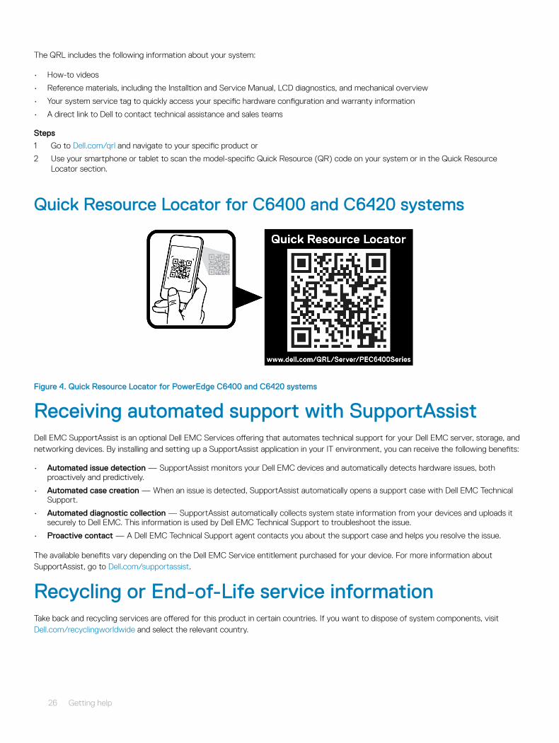
The QRL includes the following information about your system:
• How-to videos
• Reference materials, including the Installtion and Service Manual, LCD diagnostics, and mechanical overview
• Your system service tag to quickly access your specific hardware configuration and warranty information
• A direct link to Dell to contact technical assistance and sales teams
Steps
1 Go to Dell.com/qrl and navigate to your specific product or
2 Use your smartphone or tablet to scan the model-specific Quick Resource (QR) code on your system or in the Quick Resource Locator section.
Quick Resource Locator for C6400 and C6420 systems
Figure 4. Quick Resource Locator for PowerEdge C6400 and C6420 systems
Receiving automated support with SupportAssist Dell EMC SupportAssist is an optional Dell EMC Services offering that automates technical support for your Dell EMC server, storage, and networking devices. By installing and setting up a SupportAssist application in your IT environment, you can receive the following benefits:
• Automated issue detection — SupportAssist monitors your Dell EMC devices and automatically detects hardware issues, both proactively and predictively.
• Automated case creation — When an issue is detected, SupportAssist automatically opens a support case with Dell EMC Technical Support.
• Automated diagnostic collection — SupportAssist automatically collects system state information from your devices and uploads it securely to Dell EMC. This information is used by Dell EMC Technical Support to troubleshoot the issue.
• Proactive contact — A Dell EMC Technical Support agent contacts you about the support case and helps you resolve the issue.
The available benefits vary depending on the Dell EMC Service entitlement purchased for your device. For more information about SupportAssist, go to Dell.com/supportassist.
Recycling or End-of-Life service informationTake back and recycling services are offered for this product in certain countries. If you want to dispose of system components, visit Dell.com/recyclingworldwide and select the relevant country.
26 Getting help