Embed Size (px)
Citation preview
Dell EMC PowerEdge R840
Designed to drive fast insights, the PowerEdge R840 delivers four-socket performance in a dense 2U design. Power your business-critical workloads with up to 24 direct-attached NVMe drives and up to two GPUs or up to two FPGAs.
Technical Guide

© 2017 - 2018 Dell Inc. or its subsidiaries. All rights reserved. Dell, EMC, and other trademarks are trademarks of Dell Inc. or its subsidiaries. Other trademarks may be trademarks of their respective owners.
2018 - 05
Rev. A01
Contents
1 System overview............................................................................................................. 5Introduction........................................................................................................................................................................ 5New technologies...............................................................................................................................................................5
2 System features.............................................................................................................. 7Product comparison............................................................................................................................................................7Technical specifications...................................................................................................................................................... 8
3 Chassis views and features.............................................................................................11Front view of the system................................................................................................................................................... 11
Left control panel........................................................................................................................................................ 12Right control panel view..............................................................................................................................................13
Back view of the system................................................................................................................................................... 13Internal chassis view......................................................................................................................................................... 15Security features...............................................................................................................................................................16
4 Processors..................................................................................................................... 17Processor features............................................................................................................................................................ 17Supported processors....................................................................................................................................................... 17Chipset.............................................................................................................................................................................20
5 System memory............................................................................................................ 22System memory population guidelines..............................................................................................................................22General memory module installation guidelines................................................................................................................. 24NVDIMM-N memory module installation guidelines ......................................................................................................... 24
6 Storage......................................................................................................................... 25Supported Drives............................................................................................................................................................. 25PERC Controller .............................................................................................................................................................. 25IDSDM or vFlash module..................................................................................................................................................26Optical Drives...................................................................................................................................................................26Tape Drives.......................................................................................................................................................................26Boot Optimized Storage Subsystem................................................................................................................................. 27
7 Networking and PCIe.................................................................................................... 30Network daughter card.................................................................................................................................................... 30PCIe Risers and slots........................................................................................................................................................30
PCIe Expansion card riser............................................................................................................................................31
8 Trusted platform module .............................................................................................. 34
9 Power, Thermal, and Acoustics..................................................................................... 35
3
Power consumption and energy efficiency....................................................................................................................... 35Power supply units........................................................................................................................................................... 36Thermal and Acoustics..................................................................................................................................................... 36
Thermal design...........................................................................................................................................................36Acoustical design........................................................................................................................................................36
10 Rack rails..................................................................................................................... 38Sliding rails features summary...........................................................................................................................................38Strain Relief Bar............................................................................................................................................................... 39
11 Dell EMC OpenManage systems management............................................................. 40OpenManage systems management................................................................................................................................ 40iDRAC with Lifecycle controller......................................................................................................................................... 41
iDRAC features and comparison..................................................................................................................................41Dell EMC consoles............................................................................................................................................................46Dell EMC OpenManage systems management tools, utilities and protocols......................................................................47Integration with third-party consoles................................................................................................................................49OpenManage connections with third-party consoles....................................................................................................... 49
12 Appendix A. Additional specifications........................................................................... 51PSU specifications............................................................................................................................................................ 51Chassis dimensions.......................................................................................................................................................... 52Chassis weight................................................................................................................................................................. 53Environmental specifications............................................................................................................................................ 53Video specifications..........................................................................................................................................................53
13 Appendix B. Standards compliance.............................................................................. 54
14 Appendix C Additional resources..................................................................................55
15 Appendix D. Support and deployment services ........................................................... 56ProDeploy Enterprise Suite...............................................................................................................................................56
ProDeploy Plus...........................................................................................................................................................56ProDeploy.................................................................................................................................................................. 56Basic Deployment.......................................................................................................................................................56
ProSupport Enterprise Suite.............................................................................................................................................57ProSupport Plus............................................................................................................................................................... 57ProSupport.......................................................................................................................................................................58ProSupport One for Data Center......................................................................................................................................58Support Technologies.......................................................................................................................................................58
SupportAssist.............................................................................................................................................................58TechDirect..................................................................................................................................................................59
Additional professional services........................................................................................................................................ 59Dell Education Services.................................................................................................................................................... 59Dell Global Infrastructure Consulting Services.................................................................................................................. 59Dell managed services......................................................................................................................................................59
4
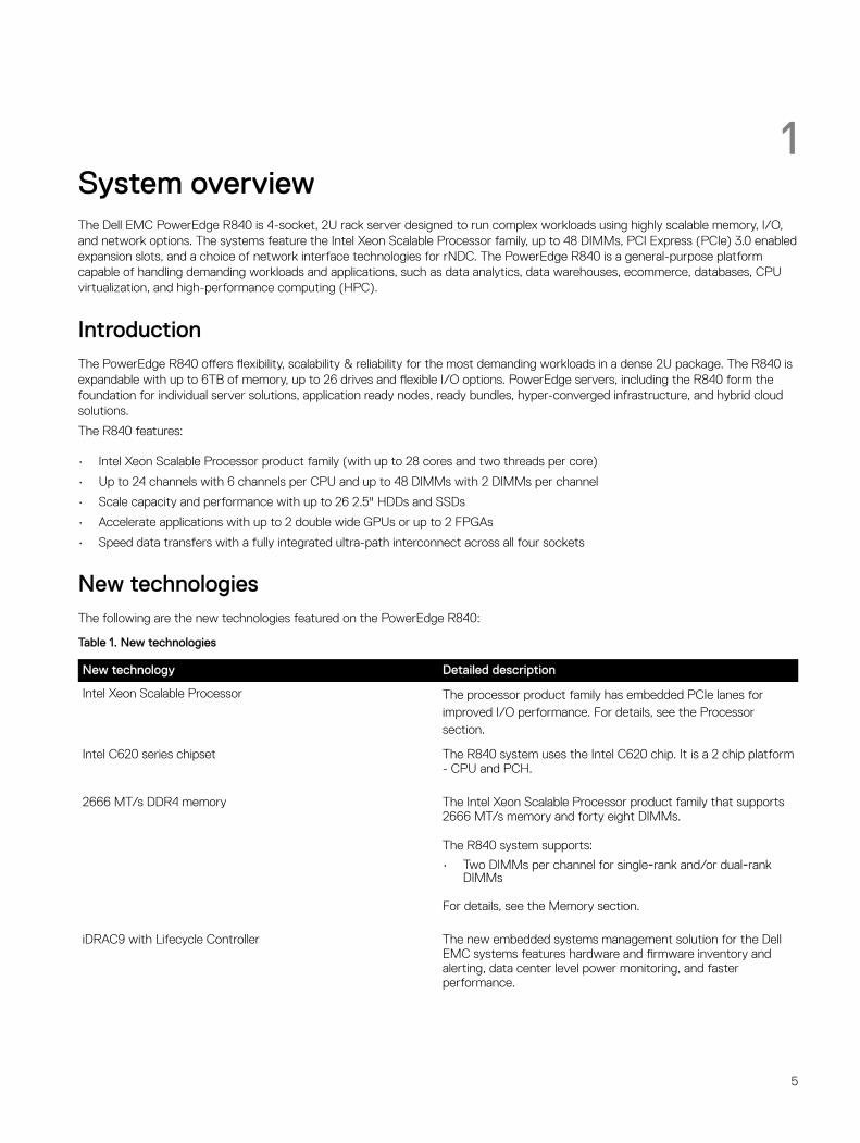
1System overviewThe Dell EMC PowerEdge R840 is 4-socket, 2U rack server designed to run complex workloads using highly scalable memory, I/O, and network options. The systems feature the Intel Xeon Scalable Processor family, up to 48 DIMMs, PCI Express (PCIe) 3.0 enabled expansion slots, and a choice of network interface technologies for rNDC. The PowerEdge R840 is a general-purpose platform capable of handling demanding workloads and applications, such as data analytics, data warehouses, ecommerce, databases, CPU virtualization, and high-performance computing (HPC).
IntroductionThe PowerEdge R840 offers flexibility, scalability & reliability for the most demanding workloads in a dense 2U package. The R840 is expandable with up to 6TB of memory, up to 26 drives and flexible I/O options. PowerEdge servers, including the R840 form the foundation for individual server solutions, application ready nodes, ready bundles, hyper-converged infrastructure, and hybrid cloud solutions.
The R840 features:
• Intel Xeon Scalable Processor product family (with up to 28 cores and two threads per core)
• Up to 24 channels with 6 channels per CPU and up to 48 DIMMs with 2 DIMMs per channel
• Scale capacity and performance with up to 26 2.5" HDDs and SSDs
• Accelerate applications with up to 2 double wide GPUs or up to 2 FPGAs
• Speed data transfers with a fully integrated ultra-path interconnect across all four sockets
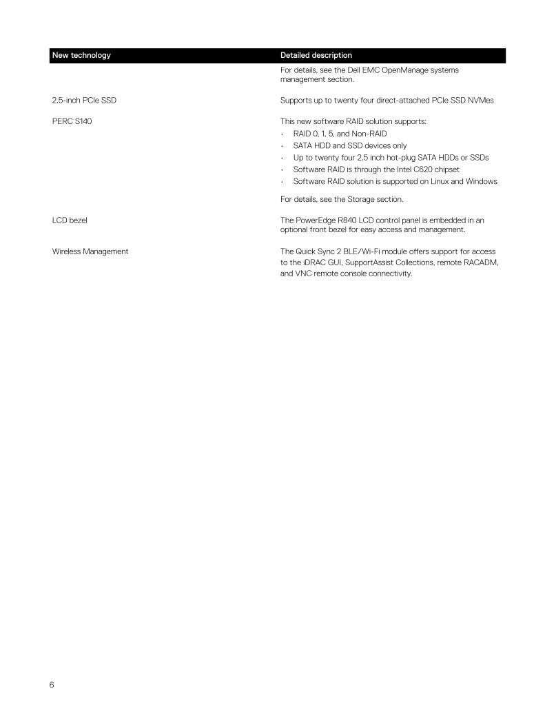
New technologiesThe following are the new technologies featured on the PowerEdge R840:
Table 1. New technologies
New technology Detailed description
Intel Xeon Scalable Processor The processor product family has embedded PCIe lanes for improved I/O performance. For details, see the Processor section.
Intel C620 series chipset The R840 system uses the Intel C620 chip. It is a 2 chip platform - CPU and PCH.
2666 MT/s DDR4 memory The Intel Xeon Scalable Processor product family that supports 2666 MT/s memory and forty eight DIMMs.
The R840 system supports:
• Two DIMMs per channel for single‐rank and/or dual‐rank DIMMs
For details, see the Memory section.
iDRAC9 with Lifecycle Controller The new embedded systems management solution for the Dell EMC systems features hardware and firmware inventory and alerting, data center level power monitoring, and faster performance.
5
New technology Detailed description
For details, see the Dell EMC OpenManage systems management section.
2.5-inch PCIe SSD Supports up to twenty four direct-attached PCIe SSD NVMes
PERC S140 This new software RAID solution supports:
• RAID 0, 1, 5, and Non-RAID
• SATA HDD and SSD devices only
• Up to twenty four 2.5 inch hot-plug SATA HDDs or SSDs
• Software RAID is through the Intel C620 chipset
• Software RAID solution is supported on Linux and Windows
For details, see the Storage section.
LCD bezel The PowerEdge R840 LCD control panel is embedded in an optional front bezel for easy access and management.
Wireless Management The Quick Sync 2 BLE/Wi-Fi module offers support for access to the iDRAC GUI, SupportAssist Collections, remote RACADM, and VNC remote console connectivity.
6
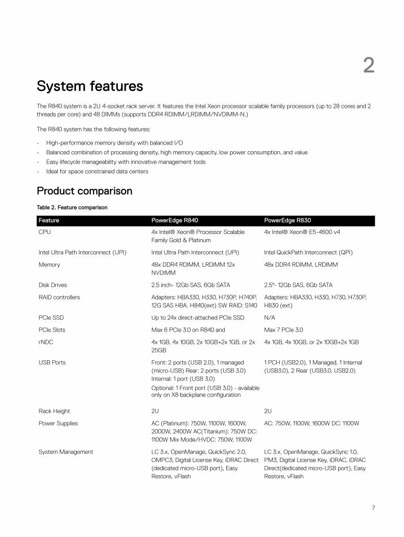
2System featuresThe R840 system is a 2U 4-socket rack server. It features the Intel Xeon processor scalable family processors (up to 28 cores and 2 threads per core) and 48 DIMMs (supports DDR4 RDIMM/LRDIMM/NVDIMM-N.)
The R840 system has the following features:
• High-performance memory density with balanced I/O
• Balanced combination of processing density, high memory capacity, low power consumption, and value
• Easy lifecycle manageability with innovative management tools
• Ideal for space constrained data centers
Product comparisonTable 2. Feature comparison
Feature PowerEdge R840 PowerEdge R830
CPU 4x Intel® Xeon® Processor Scalable Family Gold & Platinum
4x Intel® Xeon® E5-4600 v4
Intel Ultra Path Interconnect (UPI) Intel Ultra Path Interconnect (UPI) Intel QuickPath Interconnect (QPI)
Memory 48x DDR4 RDIMM, LRDIMM 12x NVDIMM
48x DDR4 RDIMM, LRDIMM
Disk Drives 2.5 inch- 12Gb SAS, 6Gb SATA 2.5"- 12Gb SAS, 6Gb SATA
RAID controllers Adapters: HBA330, H330, H730P, H740P, 12G SAS HBA, H840(ext) SW RAID: S140
Adapters: HBA330, H330, H730, H730P, H830 (ext)
PCIe SSD Up to 24x direct-attached PCIe SSD N/A
PCIe Slots Max 6 PCIe 3.0 on R840 and Max 7 PCIe 3.0
rNDC 4x 1GB, 4x 10GB, 2x 10GB+2x 1GB, or 2x 25GB
4x 1GB, 4x 10GB, or 2x 10GB+2x 1GB
USB Ports Front: 2 ports (USB 2.0), 1 managed (micro-USB) Rear: 2 ports (USB 3.0) Internal: 1 port (USB 3.0)
Optional: 1 Front port (USB 3.0) - available only on X8 backplane configuration
1 PCH (USB2.0), 1 Managed, 1 Internal (USB3.0), 2 Rear (USB3.0, USB2.0)
Rack Height 2U 2U
Power Supplies AC (Platinum): 750W, 1100W, 1600W, 2000W, 2400W AC(Titanium): 750W DC: 1100W Mix Mode/HVDC: 750W, 1100W
AC: 750W, 1100W, 1600W DC: 1100W
System Management LC 3.x, OpenManage, QuickSync 2.0, OMPC3, Digital License Key, iDRAC Direct (dedicated micro-USB port), Easy Restore, vFlash
LC 3.x, OpenManage, QuickSync 1.0, PM3, Digital License Key, iDRAC, iDRAC Direct(dedicated micro-USB port), Easy Restore, vFlash
7
Feature PowerEdge R840 PowerEdge R830
Internal GPU and FPGA Up to 2x 300W GPUs or up to 2 FH FPGAs
N/A
Availability Hot-plug Redundant Cooling
Hot-plug Drives
Hot-plug Redundant Power Supplies
Boot Optimized Storage Subsystem (BOSS)
IDSDM
Hot-plug Drives Hot-plug Redundant Cooling Hot-plug Redundant Power Supplies IDSDM
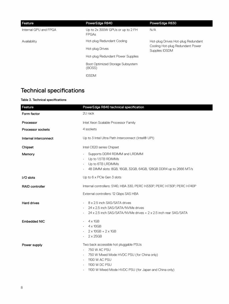
Technical specificationsTable 3. Technical specifications
Feature PowerEdge R840 technical specification
Form factor 2U rack
Processor Intel Xeon Scalable Processor Family
Processor sockets 4 sockets
Internal interconnect Up to 3 Intel Ultra Path Interconnect (Intel® UPI)
Chipset Intel C620 series Chipset
Memory • Supports DDR4 RDIMM and LRDIMM
• Up to 1.5TB RDIMMs
• Up to 6TB LRDIMMs
• 48 DIMM slots: 8GB, 16GB, 32GB, 64GB, 128GB DDR4 up to 2666 MT/s
I/O slots Up to 6 x PCIe Gen 3 slots
RAID controller Internal controllers: S140, HBA 330, PERC H330P, PERC H730P, PERC H740P
External controllers: 12 Gbps SAS HBA
Hard drives • 8 x 2.5 inch SAS/SATA drives
• 24 x 2.5 inch SAS/SATA/NVMe drives
• 24 x 2.5 inch SAS/SATA/NVMe drives + 2 x 2.5 inch rear SAS/SATA
Embedded NIC • 4 x 1GB
• 4 x 10GB
• 2 x 10GB + 2 x 1GB
• 2 x 25GB
Power supply Two back accessible hot pluggable PSUs
• 750 W AC PSU
• 750 W Mixed Mode HVDC PSU (for China only)
• 1100 W AC PSU
• 1100 W DC PSU
• 1100 W Mixed Mode HVDC PSU (for Japan and China only)
8
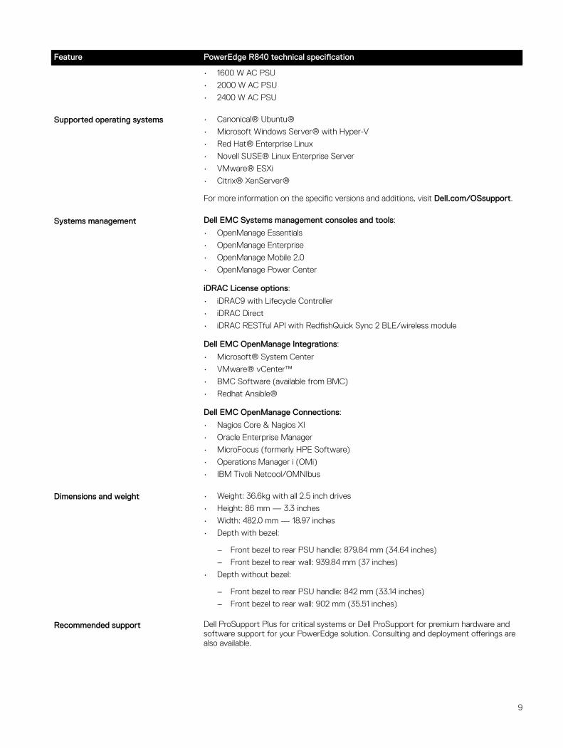
Feature PowerEdge R840 technical specification
• 1600 W AC PSU
• 2000 W AC PSU
• 2400 W AC PSU
Supported operating systems • Canonical® Ubuntu®
• Microsoft Windows Server® with Hyper-V
• Red Hat® Enterprise Linux
• Novell SUSE® Linux Enterprise Server
• VMware® ESXi
• Citrix® XenServer®
For more information on the specific versions and additions, visit Dell.com/OSsupport.
Systems management Dell EMC Systems management consoles and tools:
• OpenManage Essentials
• OpenManage Enterprise
• OpenManage Mobile 2.0
• OpenManage Power Center
iDRAC License options:
• iDRAC9 with Lifecycle Controller
• iDRAC Direct
• iDRAC RESTful API with RedfishQuick Sync 2 BLE/wireless module
Dell EMC OpenManage Integrations:
• Microsoft® System Center
• VMware® vCenter™
• BMC Software (available from BMC)
• Redhat Ansible®
Dell EMC OpenManage Connections:
• Nagios Core & Nagios XI
• Oracle Enterprise Manager
• MicroFocus (formerly HPE Software)
• Operations Manager i (OMi)
• IBM Tivoli Netcool/OMNIbus
Dimensions and weight • Weight: 36.6kg with all 2.5 inch drives
• Height: 86 mm — 3.3 inches
• Width: 482.0 mm — 18.97 inches
• Depth with bezel:
– Front bezel to rear PSU handle: 879.84 mm (34.64 inches)
– Front bezel to rear wall: 939.84 mm (37 inches)
• Depth without bezel:
– Front bezel to rear PSU handle: 842 mm (33.14 inches)
– Front bezel to rear wall: 902 mm (35.51 inches)
Recommended support Dell ProSupport Plus for critical systems or Dell ProSupport for premium hardware and software support for your PowerEdge solution. Consulting and deployment offerings are also available.
9

Feature PowerEdge R840 technical specification
Contact your Dell representative for more information. Availability and terms of Dell Services vary by region. For more information, visit Dell.com/ ServiceDescriptions.
10
3Chassis views and featuresThe PowerEdge R840 is a four socket, 2U rack system that is available in three different chassis configurations:
• Eight hard drive chassis
• Twenty four hard drives chassis
• Twenty four hard drives plus 2 rear drives chassis
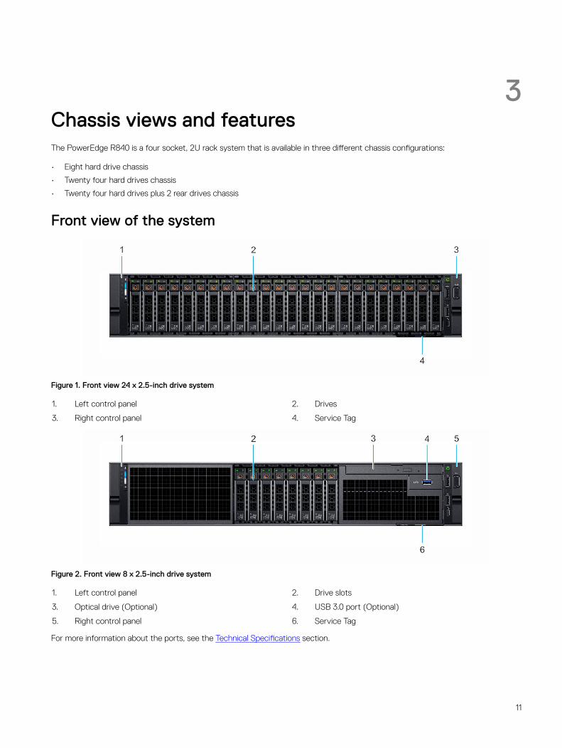
Front view of the system
Figure 1. Front view 24 x 2.5-inch drive system
1. Left control panel 2. Drives
3. Right control panel 4. Service Tag
Figure 2. Front view 8 x 2.5-inch drive system
1. Left control panel 2. Drive slots
3. Optical drive (Optional) 4. USB 3.0 port (Optional)
5. Right control panel 6. Service Tag
For more information about the ports, see the Technical Specifications section.
11
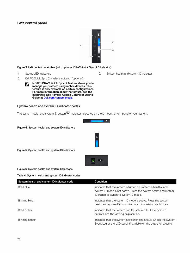
Left control panel
Figure 3. Left control panel view (with optional iDRAC Quick Sync 2.0 indicator)
1. Status LED indicators 2. System health and system ID indicator
3. iDRAC Quick Sync 2 wireless indicator (optional)
NOTE: iDRAC Quick Sync 2 feature allows you to manage your system using mobile devices. This feature is only available on certain configurations. For more information about the feature, see the Integrated Dell Remote Access Controller User's Guide at Dell.com/idracmanuals.
System health and system ID indicator codes
The system health and system ID button indicator is located on the left controlfront panel of your system.
Figure 4. System health and system ID indicators
Figure 5. System health and system ID indicators
Figure 6. System health and system ID buttons
Table 4. System health and system ID indicator codes
System health and system ID indicator code Condition
Solid blue Indicates that the system is turned on, system is healthy, and system ID mode is not active. Press the system health and system ID button to switch to system ID mode.
Blinking blue Indicates that the system ID mode is active. Press the system health and system ID button to switch to system health mode.
Solid amber Indicates that the system is in fail-safe mode. If the problem persists, see the Getting help section.
Blinking amber Indicates that the system is experiencing a fault. Check the System Event Log or the LCD panel, if available on the bezel, for specific
12
System health and system ID indicator code Condition
error messages. For more information about error messages, see the Dell Event and Error Messages Reference Guide at Dell.com/openmanagemanuals > OpenManage software.
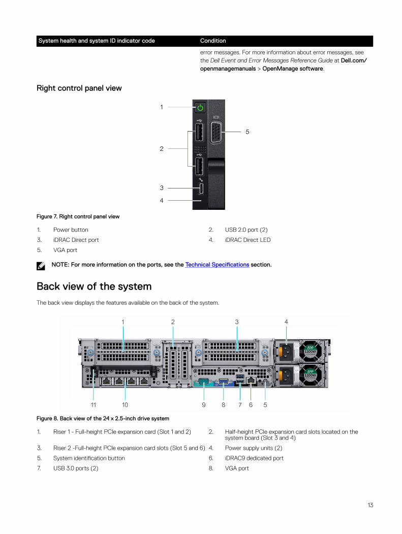
Right control panel view
Figure 7. Right control panel view
1. Power button 2. USB 2.0 port (2)
3. iDRAC Direct port 4. iDRAC Direct LED
5. VGA port
NOTE: For more information on the ports, see the Technical Specifications section.
Back view of the systemThe back view displays the features available on the back of the system.
Figure 8. Back view of the 24 x 2.5-inch drive system
1. Riser 1 - Full-height PCIe expansion card (Slot 1 and 2) 2. Half-height PCIe expansion card slots located on the system board (Slot 3 and 4)
3. Riser 2 -Full-height PCIe expansion card slots (Slot 5 and 6) 4. Power supply units (2)
5. System identification button 6. iDRAC9 dedicated port
7. USB 3.0 ports (2) 8. VGA port
13
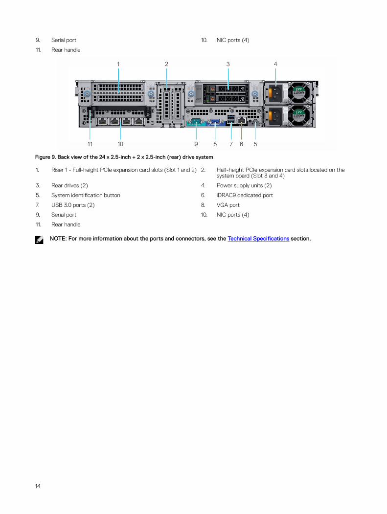
9. Serial port 10. NIC ports (4)
11. Rear handle
Figure 9. Back view of the 24 x 2.5-inch + 2 x 2.5-inch (rear) drive system
1. Riser 1 - Full-height PCIe expansion card slots (Slot 1 and 2) 2. Half-height PCIe expansion card slots located on the system board (Slot 3 and 4)
3. Rear drives (2) 4. Power supply units (2)
5. System identification button 6. iDRAC9 dedicated port
7. USB 3.0 ports (2) 8. VGA port
9. Serial port 10. NIC ports (4)
11. Rear handle
NOTE: For more information about the ports and connectors, see the Technical Specifications section.
14
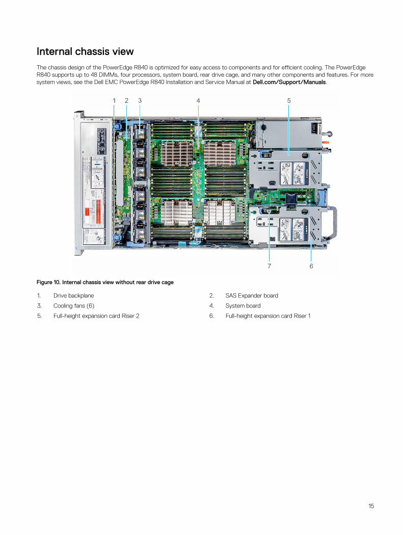
Internal chassis viewThe chassis design of the PowerEdge R840 is optimized for easy access to components and for efficient cooling. The PowerEdge R840 supports up to 48 DIMMs, four processors, system board, rear drive cage, and many other components and features. For more system views, see the Dell EMC PowerEdge R840 Installation and Service Manual at Dell.com/Support/Manuals.
Figure 10. Internal chassis view without rear drive cage
1. Drive backplane 2. SAS Expander board
3. Cooling fans (6) 4. System board
5. Full-height expansion card Riser 2 6. Full-height expansion card Riser 1
15
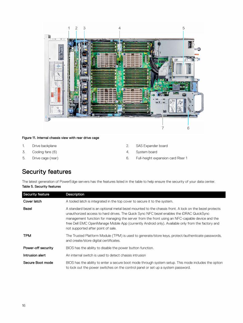
Figure 11. Internal chassis view with rear drive cage
1. Drive backplane 2. SAS Expander board
3. Cooling fans (6) 4. System board
5. Drive cage (rear) 6. Full-height expansion card Riser 1
Security featuresThe latest generation of PowerEdge servers has the features listed in the table to help ensure the security of your data center.Table 5. Security features
Security feature Description
Cover latch A tooled latch is integrated in the top cover to secure it to the system.
Bezel A standard bezel is an optional metal bezel mounted to the chassis front. A lock on the bezel protects unauthorized access to hard drives. The Quick Sync NFC bezel enables the iDRAC QuickSync management function for managing the server from the front using an NFC-capable device and the free Dell EMC OpenManage Mobile App (currently Android only). Available only from the factory and not supported after point of sale.
TPM The Trusted Platform Module (TPM) is used to generate/store keys, protect/authenticate passwords, and create/store digital certificates.
Power-off security BIOS has the ability to disable the power button function.
Intrusion alert An internal switch is used to detect chassis intrusion
Secure Boot mode BIOS has the ability to enter a secure boot mode through system setup. This mode includes the option to lock out the power switches on the control panel or set up a system password.
16
4ProcessorsThe PowerEdge R840 server features the exceptional performance, value, and power efficiency of the Intel Xeon Scalable Processor. These processors can provide high performance no matter what your constraint—floor space, power, or budget—and on workloads that range from the most complicated scientific exploration to crucial web-serving and infrastructure applications. In addition to providing raw performance gains, improved I/O is also made possible with Intel Integrated I/O, which can reduce latency by adding more lanes and doubling bandwidth. This helps to reduce network and storage bottlenecks, which improves the processor performance capabilities.
Processor featuresThe new processor family is the next generation core architecture with improved Instructions per Cycle (IPC) and other architectural improvements.
The Intel Xeon Scalable Processor family not only adds new features, but also improves upon many features of the predecessor Intel Xeon processor E5-2600 v4 product family, including:
• Virtual address space of 48 bits and a physical address space of 46 bits
• Intel Hyper-Threading Technology (Intel® HT Technology) when enabled allow each core to support two threads
• First-Level Cache (FLC) 64 KB total. The FLC is composed of a 32 KB ICU (Instruction Cache) and 32 KB DCU—Data Cache
• MB MidLevel Cache (MLC) per core (noninclusive with the LLC)
• Intel® Advanced Vector Extensions 512 (Intel® AVX-512) with a single AVX512 fused multiply-add (FMA) execution units. Processors which support Advanced RAS enable a second FMA execution unit.
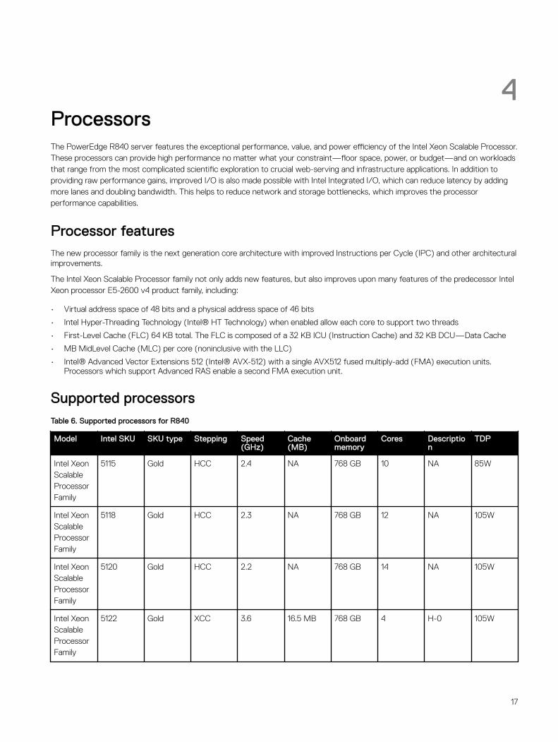
Supported processorsTable 6. Supported processors for R840
Model Intel SKU SKU type Stepping Speed (GHz)
Cache (MB)
Onboard memory
Cores Description
TDP
Intel Xeon Scalable Processor Family
5115 Gold HCC 2.4 NA 768 GB 10 NA 85W
Intel Xeon Scalable Processor Family
5118 Gold HCC 2.3 NA 768 GB 12 NA 105W
Intel Xeon Scalable Processor Family
5120 Gold HCC 2.2 NA 768 GB 14 NA 105W
Intel Xeon Scalable Processor Family
5122 Gold XCC 3.6 16.5 MB 768 GB 4 H-0 105W
17
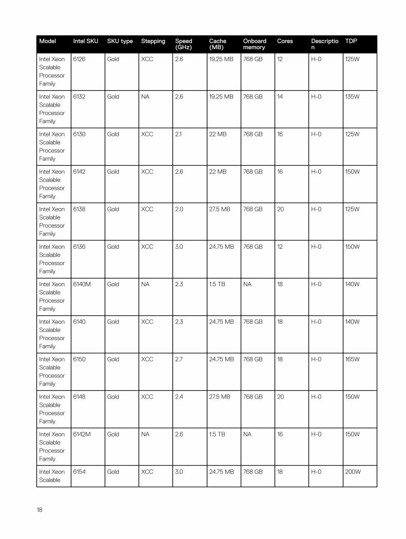
Model Intel SKU SKU type Stepping Speed (GHz)
Cache (MB)
Onboard memory
Cores Description
TDP
Intel Xeon Scalable Processor Family
6126 Gold XCC 2.6 19.25 MB 768 GB 12 H-0 125W
Intel Xeon Scalable Processor Family
6132 Gold NA 2.6 19.25 MB 768 GB 14 H-0 135W
Intel Xeon Scalable Processor Family
6130 Gold XCC 2.1 22 MB 768 GB 16 H-0 125W
Intel Xeon Scalable Processor Family
6142 Gold XCC 2.6 22 MB 768 GB 16 H-0 150W
Intel Xeon Scalable Processor Family
6138 Gold XCC 2.0 27.5 MB 768 GB 20 H-0 125W
Intel Xeon Scalable Processor Family
6136 Gold XCC 3.0 24.75 MB 768 GB 12 H-0 150W
Intel Xeon Scalable Processor Family
6140M Gold NA 2.3 1.5 TB NA 18 H-0 140W
Intel Xeon Scalable Processor Family
6140 Gold XCC 2.3 24.75 MB 768 GB 18 H-0 140W
Intel Xeon Scalable Processor Family
6150 Gold XCC 2.7 24.75 MB 768 GB 18 H-0 165W
Intel Xeon Scalable Processor Family
6148 Gold XCC 2.4 27.5 MB 768 GB 20 H-0 150W
Intel Xeon Scalable Processor Family
6142M Gold NA 2.6 1.5 TB NA 16 H-0 150W
Intel Xeon Scalable
6154 Gold XCC 3.0 24.75 MB 768 GB 18 H-0 200W
18

Model Intel SKU SKU type Stepping Speed (GHz)
Cache (MB)
Onboard memory
Cores Description
TDP
Processor Family
Intel Xeon Scalable Processor Family
6134M Gold NA 3.2 24.75 MB NA 8 H-0 130W
Intel Xeon Scalable Processor Family
6134 Gold XCC 3.2 24.75 MB 768 GB 8 H-0 130W
Intel Xeon Scalable Processor Family
6128 Gold NA 3.4 19.25 MB 768 GB 6 H-0 115W
Intel Xeon Scalable Processor Family
6152 Gold XCC 2.1 30.25 MB 768 GB 22 H-0 140W
Intel Xeon Scalable Processor Family
6144 Gold NA 3.6 24.75 MB 768 GB 8 H-0 165W
Intel Xeon Scalable Processor Family
6146 Gold NA 3.4 24.75 MB 768 GB 12 H-0 165W
Intel Xeon Scalable Processor Family
8164 Platinum NA 2.0 35.75 MB 768 GB 26 H-0 150W
Intel Xeon Scalable Processor Family
8160M Platinum NA 2.1 1.5 TB NA 24 H-0 150W
Intel Xeon Scalable Processor Family
8160 Platinum XCC 2.1 33 MB 768 GB 24 H-0 150W
Intel Xeon Scalable Processor Family
8168 Platinum XCC 2.7 33 MB 768GB 24 H-0 205W
Intel Xeon Scalable Processor Family
8170M Platinum NA 2.1 1.5 TB NA 26 H-0 165W
19
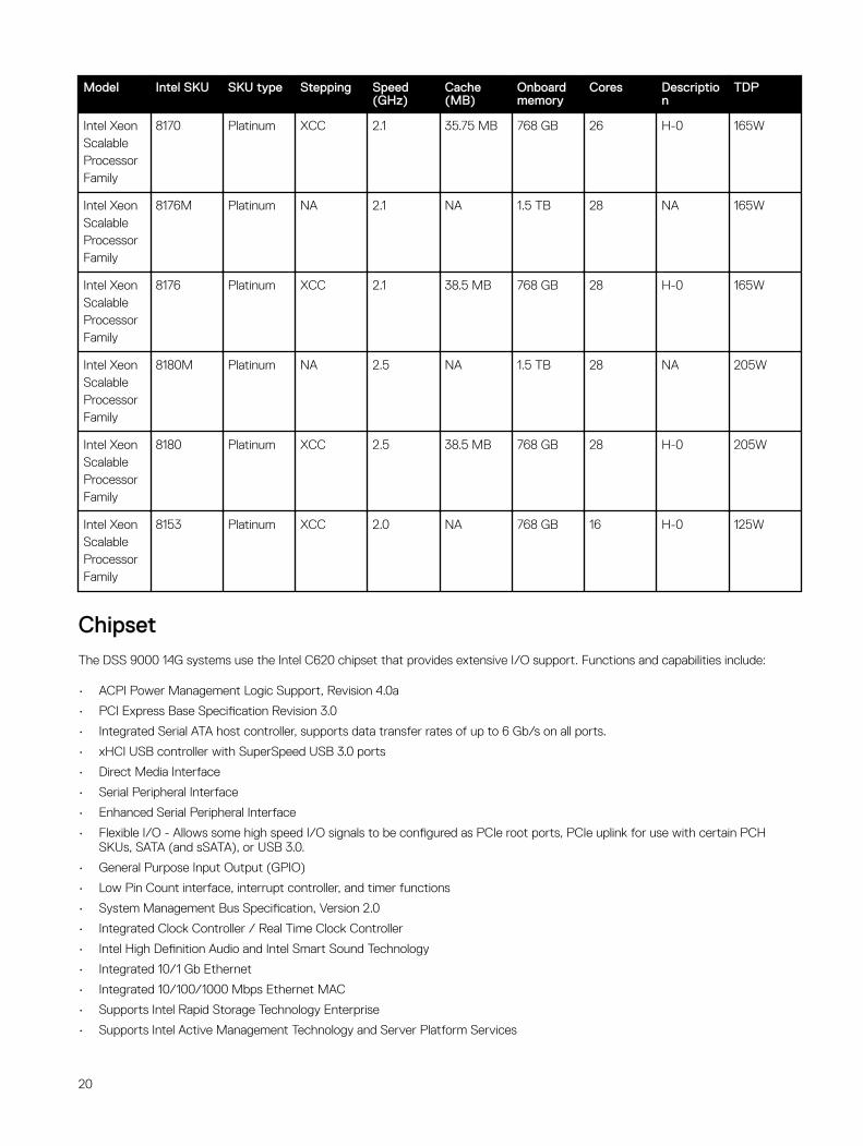
Model Intel SKU SKU type Stepping Speed (GHz)
Cache (MB)
Onboard memory
Cores Description
TDP
Intel Xeon Scalable Processor Family
8170 Platinum XCC 2.1 35.75 MB 768 GB 26 H-0 165W
Intel Xeon Scalable Processor Family
8176M Platinum NA 2.1 NA 1.5 TB 28 NA 165W
Intel Xeon Scalable Processor Family
8176 Platinum XCC 2.1 38.5 MB 768 GB 28 H-0 165W
Intel Xeon Scalable Processor Family
8180M Platinum NA 2.5 NA 1.5 TB 28 NA 205W
Intel Xeon Scalable Processor Family
8180 Platinum XCC 2.5 38.5 MB 768 GB 28 H-0 205W
Intel Xeon Scalable Processor Family
8153 Platinum XCC 2.0 NA 768 GB 16 H-0 125W
ChipsetThe DSS 9000 14G systems use the Intel C620 chipset that provides extensive I/O support. Functions and capabilities include:
• ACPI Power Management Logic Support, Revision 4.0a
• PCI Express Base Specification Revision 3.0
• Integrated Serial ATA host controller, supports data transfer rates of up to 6 Gb/s on all ports.
• xHCI USB controller with SuperSpeed USB 3.0 ports
• Direct Media Interface
• Serial Peripheral Interface
• Enhanced Serial Peripheral Interface
• Flexible I/O - Allows some high speed I/O signals to be configured as PCIe root ports, PCIe uplink for use with certain PCH SKUs, SATA (and sSATA), or USB 3.0.
• General Purpose Input Output (GPIO)
• Low Pin Count interface, interrupt controller, and timer functions
• System Management Bus Specification, Version 2.0
• Integrated Clock Controller / Real Time Clock Controller
• Intel High Definition Audio and Intel Smart Sound Technology
• Integrated 10/1 Gb Ethernet
• Integrated 10/100/1000 Mbps Ethernet MAC
• Supports Intel Rapid Storage Technology Enterprise
• Supports Intel Active Management Technology and Server Platform Services
20

• Supports Intel Server Platform Service firmware
• Supports Intel Virtualization Technology for Directed I/O
• Supports Intel Trusted Execution Technology
• JTAG Boundary Scan support
• Intel QuickAssist Technology
• Intel PCIe QuickAssist card
• Intel Trace Hub for debug
For more information, visit Intel.com
21
5System memoryThe system supports DDR4 registered DIMM (RDIMMs) slots, load reduced DIMM (LRDIMMs) slots and non-volatile dual in-line DIMM-Ns (NVDIMM-Ns). System memory holds the instructions that are executed by the processor.
System memory population guidelinesNOTE: MT/s indicates DIMM speed in MegaTransfers per second.
Memory bus operating frequency can be 2666 MT/s, 2400 MT/s, 2133, or 1866 MT/s depending on the following factors:
• DIMM type (RDIMM or LRDIMM)
• Number of DIMM slots populated per channel
• System profile selected (for example, Performance Optimized, or Custom [can be run at any supported speed])
• Maximum supported DIMM frequency of the processors
The R840 contains 48 memory sockets split into four sets of 12 sockets, one set per processor.
22
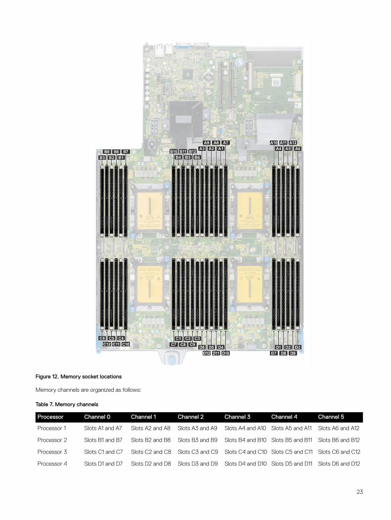
Figure 12. Memory socket locations
Memory channels are organized as follows:
Table 7. Memory channels
Processor Channel 0 Channel 1 Channel 2 Channel 3 Channel 4 Channel 5
Processor 1 Slots A1 and A7 Slots A2 and A8 Slots A3 and A9 Slots A4 and A10 Slots A5 and A11 Slots A6 and A12
Processor 2 Slots B1 and B7 Slots B2 and B8 Slots B3 and B9 Slots B4 and B10 Slots B5 and B11 Slots B6 and B12
Processor 3 Slots C1 and C7 Slots C2 and C8 Slots C3 and C9 Slots C4 and C10 Slots C5 and C11 Slots C6 and C12
Processor 4 Slots D1 and D7 Slots D2 and D8 Slots D3 and D9 Slots D4 and D10 Slots D5 and D11 Slots D6 and D12
23
General memory module installation guidelinesNOTE: If you do not observe the system's memory configuration guidelines, your system might not boot, might stop responding during memory configuration, or might operate with reduced memory.
The system supports Flexible Memory Configuration, enabling the system to be configured and run in any valid chipset architectural configuration. The following are the recommended guidelines for installing memory modules:
• Only DDR4 RDIMMs, LRDIMMs, and NVDIMMs are supported.
• RDIMMs and LRDIMMs must not be mixed.
• NVDIMMs and LRDIMMs must not be mixed.
• NVDIMMs and RDIMMs can be mixed.
• 64 GB LRDIMMS that are DDP (Dual Die Package) LRDIMMs must not be mixed with 128 GB LRDIMMs that are TSV (Through Silicon Via/3DS) LRDIMMs.
• x4 and x8 DRAM based memory modules can be mixed. For more information, see the Mode-specific guidelines section.
• Up to two RDIMMs can be populated per channel regardless of rank count.
• Up to two LRDIMMs can be populated per channel regardless of rank count.
• If memory modules with different speeds are installed, they will operate at the speed of the slowest installed memory module(s) or slower depending on the system DIMM configuration.
• Populate memory module sockets only if a processor is installed. Sockets available: A1 to A12 and B1 to B12.
• Populate all the sockets with white release tabs first, followed by the black release tabs.
• When mixing memory modules with different capacities, populate the sockets with memory modules with the highest capacity first. For example, if you want to mix 8 GB and 16 GB memory modules, populate 16 GB memory modules in the sockets with white release tabs and 8 GB memory modules in the sockets with black release tabs.
• In a dual-processor configuration, the memory configuration for each processor should be identical. For example, if you populate socket A1 for processor 1, then populate socket B1 for processor 2, and so on.
• Memory modules of different capacities can be mixed provided other memory population rules are followed (for example, 8 GB and 16 GB memory modules can be mixed).
• Mixing of more than two memory module capacities in a system is not supported.
• Populate six memory modules per processor (one DIMM per channel) at a time to maximize performance.
NVDIMM-N memory module installation guidelines The following are the recommended guidelines for installing NVDIMM-N memory modules:
• NVDIMM-Ns or RDIMMs must not be mixed with LRDIMMs.
• NVDIMM-Ns must not be mixed with AEP DIMMs.
• DDR4 NVDIMM-Ns must be populated only on the black release tabs on processor 1 and 2.
• For systems with four processors, RDIMMs populated on processor 3 and 4 must be identical to the number of RDIMMs populated on processor 1 and 2.
• All slots on configurations 3, 6, 9, and 12 can be used, but a maximum of 12 NVDIMM-Ns can be installed in a system.
For more information on the supported NVDIMM-N configurations, see the NVDIMM-N User Guide at Dell.com/poweredgemanuals.
24
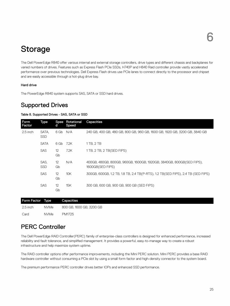
6StorageThe Dell PowerEdge R840 offer various internal and external storage controllers, drive types and different chassis and backplanes for varied numbers of drives. Features such as Express Flash PCIe SSDs, H740P and H840 Raid controller provide vastly accelerated performance over previous technologies. Dell Express Flash drives use PCIe lanes to connect directly to the processor and chipset and are easily accessible through a hot-plug drive bay.
Hard drive
The PowerEdge R840 system supports SAS, SATA or SSD hard drives.
Supported DrivesTable 8. Supported Drives - SAS, SATA or SSD
Form Factor
Type Speed
Rotational Speed
Capacities
2.5 inch SATA, SSD
6 Gb N/A 240 GB, 400 GB, 480 GB, 800 GB, 960 GB, 1600 GB, 1920 GB, 3200 GB, 3840 GB
SATA 6 Gb 7.2K 1 TB, 2 TB
SAS 12 Gb
7.2K 1 TB, 2 TB, 2 TB(SED FIPS)
SAS, SSD
12 Gb
N/A 400GB, 480GB, 800GB, 960GB, 1600GB, 1920GB, 3840GB, 800GB(SED FIPS), 1600GB(SED FIPS)
SAS 12 Gb
10K 300GB, 600GB, 1.2 TB, 1.8 TB, 2.4 TB(P-RTS), 1.2 TB(SED FIPS), 2.4 TB (SED FIPS)
SAS 12 Gb
15K 300 GB, 600 GB, 900 GB, 900 GB (SED FIPS)
Form Factor Type Capacities
2.5 inch NVMe 800 GB, 1600 GB, 3200 GB
Card NVMe PM1725
PERC Controller The Dell PowerEdge RAID Controller(PERC) family of enterprise-class controllers is designed for enhanced performance, increased reliability and fault tolerance, and simplified management. It provides a powerful, easy-to-manage way to create a robust infrastructure and help maximize system uptime.
The RAID controller options offer performance improvements, including the Mini PERC solution. Mini PERC provides a base RAID hardware controller without consuming a PCIe slot by using a small form factor and high-density connector to the system board.
The premium performance PERC controller drives better IOPs and enhanced SSD performance.
25
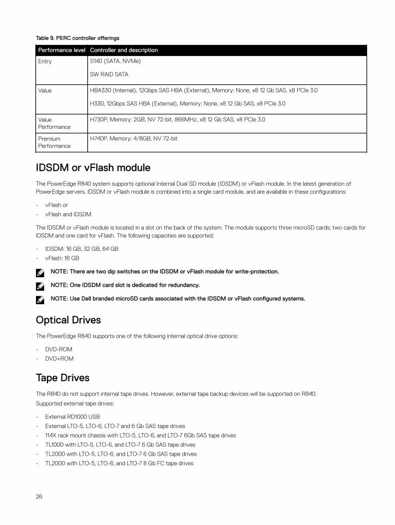
Table 9. PERC controller offerings
Performance level Controller and description
Entry S140 (SATA, NVMe)
SW RAID SATA
Value HBA330 (Internal), 12Gbps SAS HBA (External), Memory: None, x8 12 Gb SAS, x8 PCIe 3.0
H330, 12Gbps SAS HBA (External), Memory: None, x8 12 Gb SAS, x8 PCIe 3.0
Value Performance
H730P, Memory: 2GB, NV 72-bit, 866MHz, x8 12 Gb SAS, x8 PCIe 3.0
Premium Performance
H740P, Memory: 4/8GB, NV 72-bit
IDSDM or vFlash moduleThe PowerEdge R840 system supports optional Internal Dual SD module (IDSDM) or vFlash module. In the latest generation of PowerEdge servers, IDSDM or vFlash module is combined into a single card module, and are available in these configurations:
• vFlash or
• vFlash and IDSDM
The IDSDM or vFlash module is located in a slot on the back of the system. The module supports three microSD cards; two cards for IDSDM and one card for vFlash. The following capacities are supported:
• IDSDM: 16 GB, 32 GB, 64 GB
• vFlash: 16 GB
NOTE: There are two dip switches on the IDSDM or vFlash module for write-protection.
NOTE: One IDSDM card slot is dedicated for redundancy.
NOTE: Use Dell branded microSD cards associated with the IDSDM or vFlash configured systems.
Optical DrivesThe PowerEdge R840 supports one of the following internal optical drive options:
• DVD-ROM
• DVD+ROM
Tape DrivesThe R840 do not support internal tape drives. However, external tape backup devices will be supported on R840.
Supported external tape drives:
• External RD1000 USB
• External LTO-5, LTO-6, LTO-7 and 6 Gb SAS tape drives
• 114X rack mount chassis with LTO-5, LTO-6, and LTO-7 6Gb SAS tape drives
• TL1000 with LTO-5, LTO-6, and LTO-7 6 Gb SAS tape drives
• TL2000 with LTO-5, LTO-6, and LTO-7 6 Gb SAS tape drives
• TL2000 with LTO-5, LTO-6, and LTO-7 8 Gb FC tape drives
26
• TL4000 with LTO-5, LTO-6, and LTO-7 6 Gb SAS tape drives
• TL4000 with LTO-5, LTO-6, and LTO-7 8Gb FC tape drives
• ML6000 with LTO-5, LTO-6, 6 Gb SAS tape drives
• ML6000 with LTO-5, LTO-6, LTO-7 8Gb FC tape drives
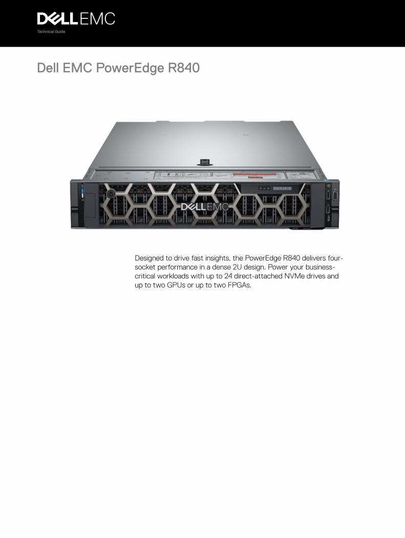
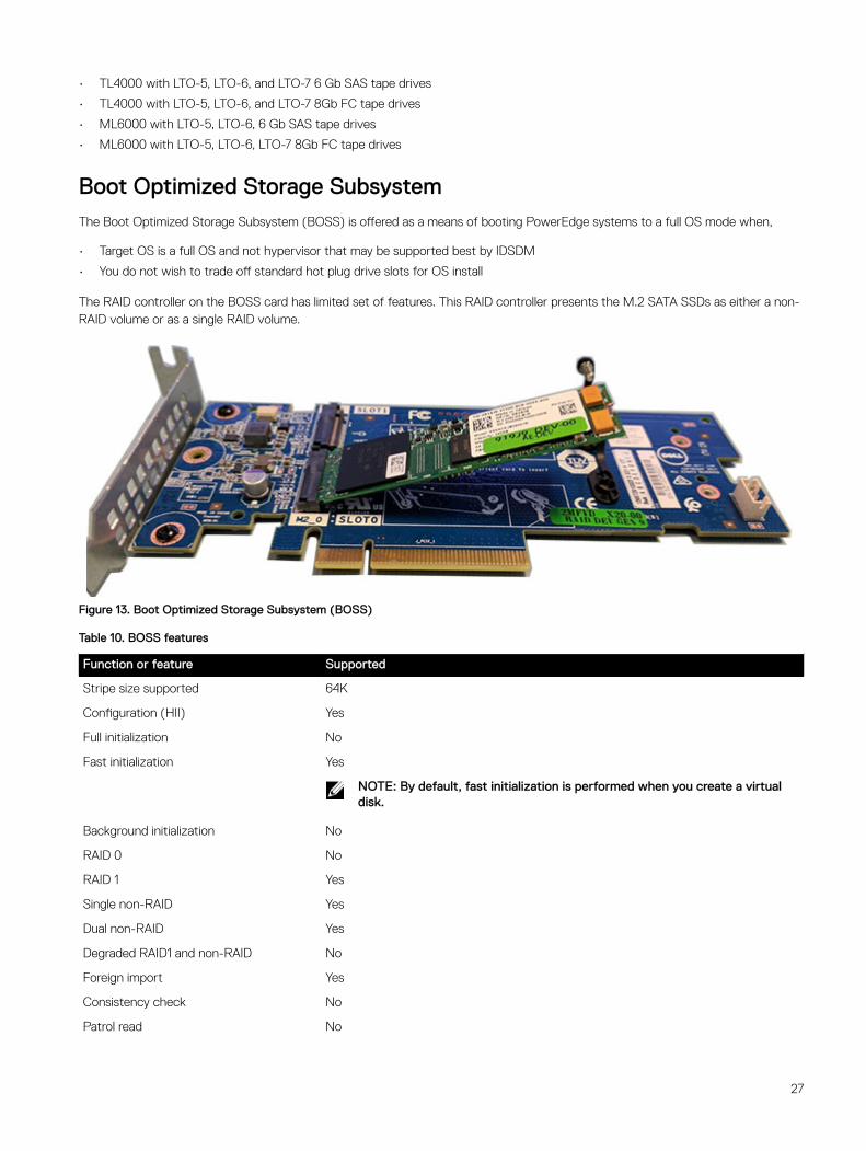
Boot Optimized Storage SubsystemThe Boot Optimized Storage Subsystem (BOSS) is offered as a means of booting PowerEdge systems to a full OS mode when,
• Target OS is a full OS and not hypervisor that may be supported best by IDSDM
• You do not wish to trade off standard hot plug drive slots for OS install
The RAID controller on the BOSS card has limited set of features. This RAID controller presents the M.2 SATA SSDs as either a non-RAID volume or as a single RAID volume.
Figure 13. Boot Optimized Storage Subsystem (BOSS)
Table 10. BOSS features
Function or feature Supported
Stripe size supported 64K
Configuration (HII) Yes
Full initialization No
Fast initialization Yes
NOTE: By default, fast initialization is performed when you create a virtual disk.
Background initialization No
RAID 0 No
RAID 1 Yes
Single non-RAID Yes
Dual non-RAID Yes
Degraded RAID1 and non-RAID No
Foreign import Yes
Consistency check No
Patrol read No
27
Function or feature Supported
Load balance N/A
Rebuild Yes
NOTE: You must manually start the rebuild process using HII or using the Marvell CLI.
Auto-rebuild Yes
NOTE: Auto-rebuild is performed when the system is powered on only if there is a surviving native virtual disk and another physical disk is present.
Hot spare No
Change rebuild priority/rate No
Virtual disk write back/read ahead cache No
NOTE: BOSS controller does not support controller cache.
Battery support N/A
NOTE: BOSS controller does not support a battery.
Non-RAID disk cache policy Yes
NOTE: OS controlled/Device defaults.
SMART Info Yes
NOTE: Use the Marvell CLI to retrieve the SMART information from the drives.
Physical disk hot swap No
Virtual disk expansion No
Virtual disk slicing No
Virtual disk migration Yes
NOTE: On new controller, virtual disk must be Imported from HII before presented to OS.
Split mirror No
NOTE: System required to shutdown and migrate one physical disk to another system and continue rebuild.
Non-RAID migration Yes
BIOS configuration utility (Ctrl-M) No
Add on driver for data path (OS device driver)
No
NOTE: Console Windows driver or Linux library is required for management purposes only.
4K native drive support No
TRIM and UNMAP virtual disk No
TRIM and UNMAP Non-RAID physical disk Yes
Self-encrypting drives(SED) support No
Cryptographic erase (sanitize) Yes
28

Function or feature Supported
NOTE: If drive supports SANITIZE Crypto Erase. No other encryption support from controller or drive.
29
7Networking and PCIeThe Dell EMC PowerEdge R840 offers offer balanced, scalable I/O capabilities, including integrated PCIe 3.0-capable expansion slots. Dell Select Network Adapters, Dell’s network daughter cards, enable you to choose the right network fabric without using up a valuable PCI slot. Pick the speed, technology, vendor, and other options, such as switch independent partitioning, which enable you to share and manage bandwidth on 10GbE connections.
Network daughter cardCAUTION: If the GPU card is installed, you cannot install the 10 GbE NDC.
PowerEdge R840 supports up to four Network Interface Controller (NIC) ports on the back panel, which are available in the following configurations:
• Four 1 Gbps
• Four 10 Gbps
• Two 10 Gbps and two 1 Gbps
• Two 25 Gbps
PCIe Risers and slotsPowerEdge R840 supports PCI express (PCIe) generation 3 expansion cards that can be installed on the system board using expansion card risers.
30
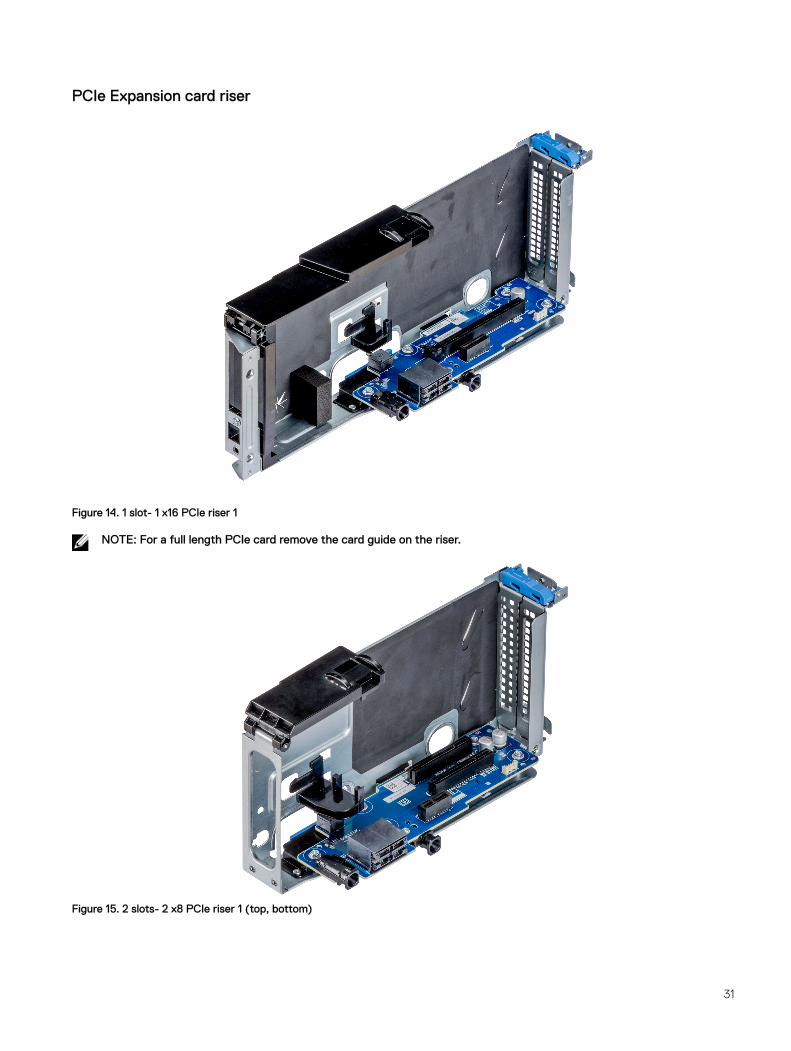
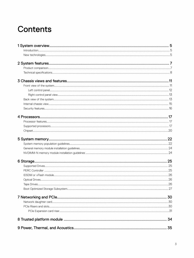
PCIe Expansion card riser
Figure 14. 1 slot- 1 x16 PCIe riser 1
NOTE: For a full length PCIe card remove the card guide on the riser.
Figure 15. 2 slots- 2 x8 PCIe riser 1 (top, bottom)
31
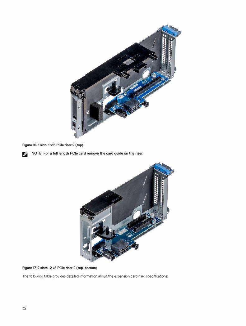
Figure 16. 1 slot- 1 x16 PCIe riser 2 (top)
NOTE: For a full length PCIe card remove the card guide on the riser.
Figure 17. 2 slots- 2 x8 PCIe riser 2 (top, bottom)
The following table provides detailed information about the expansion card riser specifications:
32
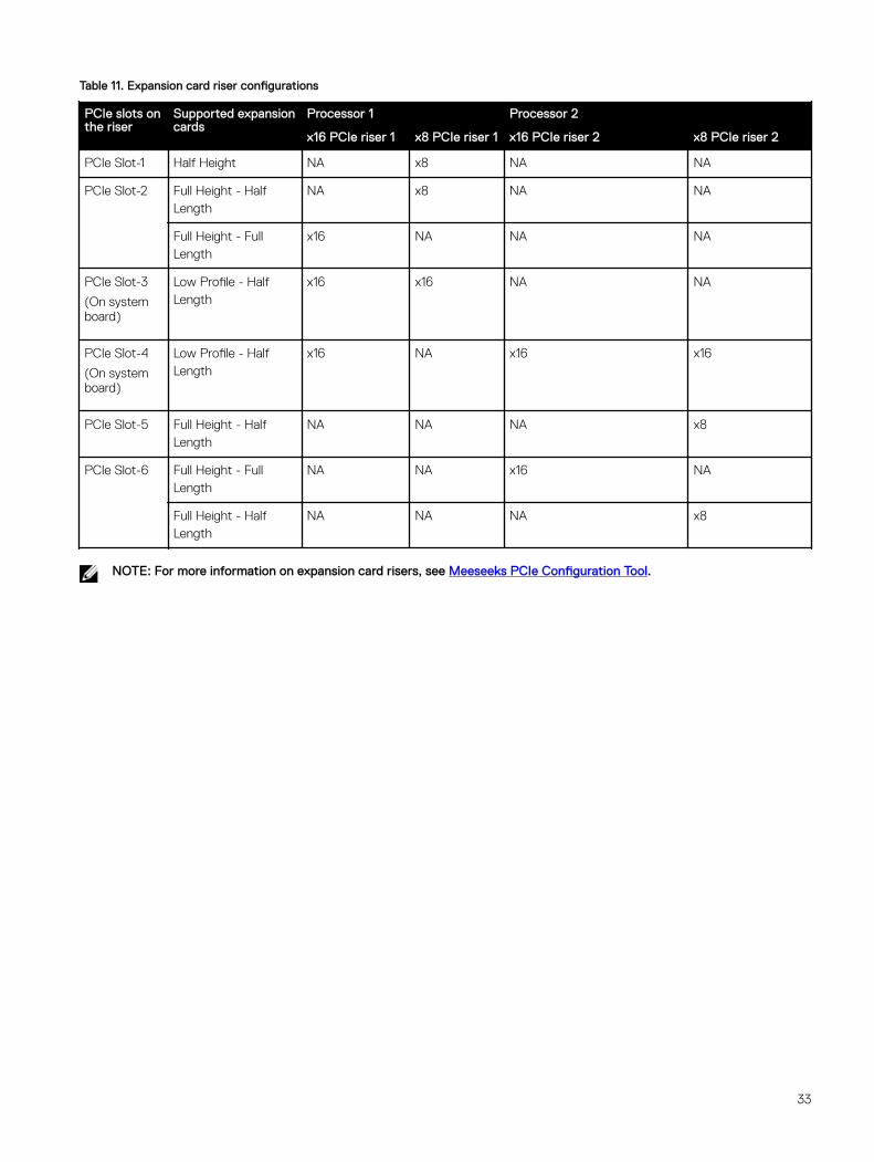
Table 11. Expansion card riser configurations
PCIe slots on the riser
Supported expansion cards
Processor 1 Processor 2
x16 PCIe riser 1 x8 PCIe riser 1 x16 PCIe riser 2 x8 PCIe riser 2
PCIe Slot-1 Half Height NA x8 NA NA
PCIe Slot-2 Full Height - Half Length
NA x8 NA NA
Full Height - Full Length
x16 NA NA NA
PCIe Slot-3
(On system board)
Low Profile - Half Length
x16 x16 NA NA
PCIe Slot-4
(On system board)
Low Profile - Half Length
x16 NA x16 x16
PCIe Slot-5 Full Height - Half Length
NA NA NA x8
PCIe Slot-6 Full Height - Full Length
NA NA x16 NA
Full Height - Half Length
NA NA NA x8
NOTE: For more information on expansion card risers, see Meeseeks PCIe Configuration Tool.
33
8Trusted platform module The Trusted Platform Module (TPM) is used to generate and store keys, protect or authenticate passwords, and create and store digital certificates. The Intel’s TXT (Trusted Execution Technology) functionality along with Microsoft’s Platform Assurance feature in Windows Server 2016 is supported. TPM can also be used to enable the BitLocker hard drive encryption feature in Windows Server 2012/2016.
The TPM chip is on the Plug-in Module (PIM) and bound only to one system board.
The system board has a connector for the plug-in module, and it is factory-installed.
There are four types of TPM module options:
• No TPM
• TPM 1.2 Nuvoton FIPS-CC-TCG
• TPM 2.0 Nuvoton FIPS-CC-TCG
• TPM 2.0 NationZ
34
9Power, Thermal, and AcousticsThe lower overall system-level power draw is a result of the breakthrough system design developed by Dell EMC. The system aims to maximize performance per watt through a combination of energy efficient technologies, optimized thermal designs and intelligent fan control algorithms. The system fan control algorithms use an extensive array of sensors that automatically monitor power and thermal activity to minimize fan speeds based on system cooling requirements, reducing the power required for cooling.
Power consumption and energy efficiencyWith the rise in the cost of energy coupled with increasing data center density, Dell EMC provides tools and technologies to help you realize greater performance with lower energy cost and wastage. More efficient data center usage can reduce costs by slowing the need for additional data center space. The following table lists the tools and technologies that Dell EMC offers to help you achieve your data center goals by lowering power consumption and increasing energy efficiency.
Table 12. Power tools and technologies
Feature Description
Power supply units (PSU) portfolio PSU portfolio includes intelligent features such as dynamically optimizing efficiency while maintaining availability and redundancy. For more information, see the Power supply units section.
Tools for right-sizing Enterprise Infrastructure Planning Tool (EIPT) is a tool that helps you plan and tune your computer and infrastructure equipment for maximum efficiency by calculating hardware power consumption, power infrastructure and storage. Learn more at Dell.com/calc.
Power monitoring accuracy PSU power monitoring improvements include:
• Power monitoring accuracy of 1%, whereas the industry standard is 5%
• More accurate reporting of power
• Better performance under a power cap
Power capping Use Dell EMC systems management tools such as OpenManage Power Center and iDRAC9 with an Enterprise license can be used to set a power limit for your server. This limits the output of a PSU and reduce system power consumption and help in constrained power situations.
Systems management The integrated Dell Remote Access Controller 9 (iDRAC9) with Lifecycle Controller is embedded within every Dell EMC PowerEdge™ server and provides functionality that helps IT administrators deploy, update, monitor, and maintain servers with no need for any additional software to be installed. iDRAC functions regardless of operating system or hypervisor presence because from a pre-OS or bare-metal state, iDRAC is ready to work because it is embedded within each server from the factory.
Active power management Dell EMC offers a complete power management solution accessed through the iDRAC9 with Enterprise licensing and OpenManage Power Center to implement policy-based management of power and thermal levels at the individual system, rack, or data center level. Hot spares reduce power consumption of redundant power supplies. Thermal control of fan speed optimizes the thermal settings for your environment to reduce fan consumption and lower system power consumption.
35
Power supply unitsEnergy Smart power supplies have intelligent features, such as the ability to dynamically optimize efficiency while maintaining availability and redundancy. Also featured are enhanced power-consumption reduction technologies, such as high-efficiency power conversion and advanced thermal-management techniques, and embedded power-management features including high-accuracy power monitoring. The system supports two hot-swappable AC power supplies with 1 + 1 redundancy, auto-sensing and auto-switching capability. A single cabled AC power supply option is also available for the R840.
Thermal and AcousticsThe system's thermal management delivers high performance through optimized cooling of components at the lowest fan speeds across a wide range of ambient temperatures from 10°C to 35°C (50°F to 95°F) and to extended ambient temperature ranges. These optimizations result in lower fan power consumption which translate to lower system power and data center power consumption.
Thermal design
The thermal design of the system reflects the following:
• Optimized thermal design: The system layout is architected for optimum thermal design. System component placement and layout are designed to provide maximum airflow coverage to critical components with minimal expense of fan power.
• Comprehensive thermal management: The thermal control system regulates the system fan speeds based on feedback from system component temperature sensors, as well as for system inventory and subsystem power draw. Temperature monitoring includes components such as processors, DIMMs, chipset, system inlet air ambient, hard disk drives, NDC, and GPU.
• Open and closed loop fan speed control: Open loop fan control uses system configuration to determine fan speed based on system inlet air temperature. Closed loop thermal control uses temperature feedback to dynamically adjust fan speeds based on system activity and cooling requirements.
• User-configurable settings: With the understanding and realization that every customer has a unique set of circumstances or expectations from the system, in this generation of servers, we have introduced limited user-configurable settings in the iDRAC9 BIOS setup screen. For more information, see the Dell EMC PowerEdge system Installation and Service Manual on Dell.com/Support/Manuals and “Advanced Thermal Control: Optimizing across Environments and Power Goals” on Dell.com.
• Cooling redundancy: The system allows N+1 fan redundancy, allowing continuous operation with one fan failure in the system.
• Environmental Specifications: The optimized thermal management makes the R840 reliable under a wide range of operating environments.
Acoustical design
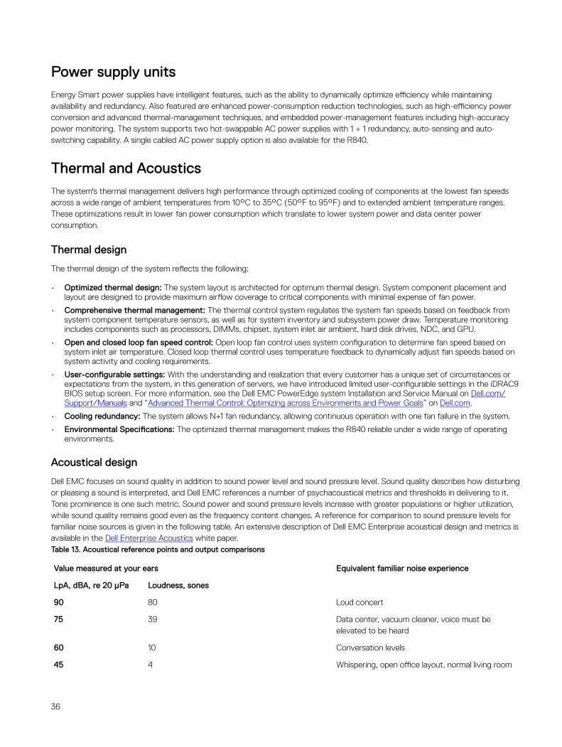
Dell EMC focuses on sound quality in addition to sound power level and sound pressure level. Sound quality describes how disturbing or pleasing a sound is interpreted, and Dell EMC references a number of psychacoustical metrics and thresholds in delivering to it. Tone prominence is one such metric. Sound power and sound pressure levels increase with greater populations or higher utilization, while sound quality remains good even as the frequency content changes. A reference for comparison to sound pressure levels for familiar noise sources is given in the following table. An extensive description of Dell EMC Enterprise acoustical design and metrics is available in the Dell Enterprise Acoustics white paper.Table 13. Acoustical reference points and output comparisons
Value measured at your ears Equivalent familiar noise experience
LpA, dBA, re 20 µPa Loudness, sones
90 80 Loud concert
75 39 Data center, vacuum cleaner, voice must be elevated to be heard
60 10 Conversation levels
45 4 Whispering, open office layout, normal living room
36

35 2 Quiet office
30 1 Quiet library
20 0 Recording studio
37
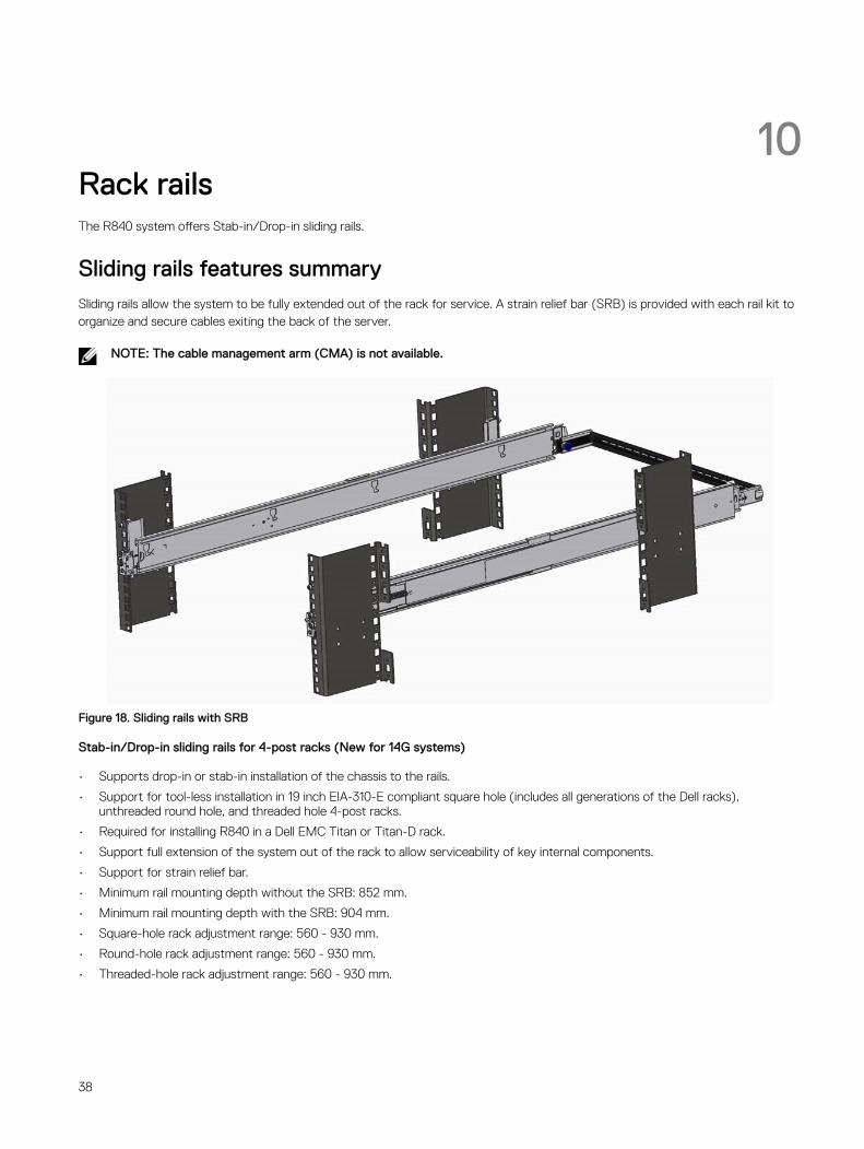
10Rack railsThe R840 system offers Stab-in/Drop-in sliding rails.
Sliding rails features summarySliding rails allow the system to be fully extended out of the rack for service. A strain relief bar (SRB) is provided with each rail kit to organize and secure cables exiting the back of the server.
NOTE: The cable management arm (CMA) is not available.
Figure 18. Sliding rails with SRB
Stab-in/Drop-in sliding rails for 4-post racks (New for 14G systems)
• Supports drop-in or stab-in installation of the chassis to the rails.
• Support for tool-less installation in 19 inch EIA-310-E compliant square hole (includes all generations of the Dell racks), unthreaded round hole, and threaded hole 4-post racks.
• Required for installing R840 in a Dell EMC Titan or Titan-D rack.
• Support full extension of the system out of the rack to allow serviceability of key internal components.
• Support for strain relief bar.
• Minimum rail mounting depth without the SRB: 852 mm.
• Minimum rail mounting depth with the SRB: 904 mm.
• Square-hole rack adjustment range: 560 - 930 mm.
• Round-hole rack adjustment range: 560 - 930 mm.
• Threaded-hole rack adjustment range: 560 - 930 mm.
38

Strain Relief Bar• Tool-less attachment to rails.
• Two depth positions to accommodate various cable bundle sizes and rack depths.
• Supports cable weight and controls stresses on server connectors.
• Cables can be segregated into discrete, purpose specific bundles.
39
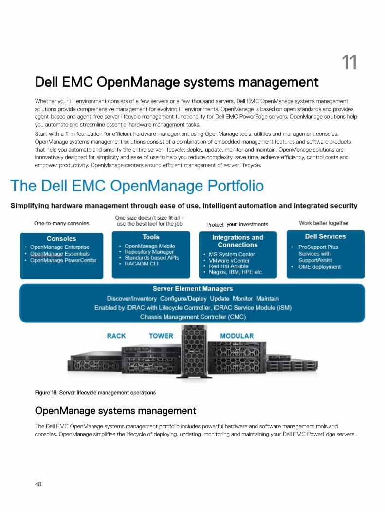
11Dell EMC OpenManage systems managementWhether your IT environment consists of a few servers or a few thousand servers, Dell EMC OpenManage systems management solutions provide comprehensive management for evolving IT environments. OpenManage is based on open standards and provides agent-based and agent-free server lifecycle management functionality for Dell EMC PowerEdge servers. OpenManage solutions help you automate and streamline essential hardware management tasks.
Start with a firm foundation for efficient hardware management using OpenManage tools, utilities and management consoles. OpenManage systems management solutions consist of a combination of embedded management features and software products that help you automate and simplify the entire server lifecycle: deploy, update, monitor and maintain. OpenManage solutions are innovatively designed for simplicity and ease of use to help you reduce complexity, save time, achieve efficiency, control costs and empower productivity. OpenManage centers around efficient management of server lifecycle.
Figure 19. Server lifecycle management operations
OpenManage systems managementThe Dell EMC OpenManage systems management portfolio includes powerful hardware and software management tools and consoles. OpenManage simplifies the lifecycle of deploying, updating, monitoring and maintaining your Dell EMC PowerEdge servers.
40
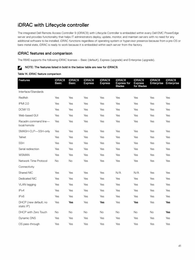
iDRAC with Lifecycle controllerThe integrated Dell Remote Access Controller 9 (iDRAC9) with Lifecycle Controller is embedded within every Dell EMC PowerEdge server and provides functionality that helps IT administrators deploy, update, monitor, and maintain servers with no need for any additional software to be installed. iDRAC functions regardless of operating system or hypervisor presence because from a pre-OS or bare-metal state, iDRAC is ready to work because it is embedded within each server from the factory.
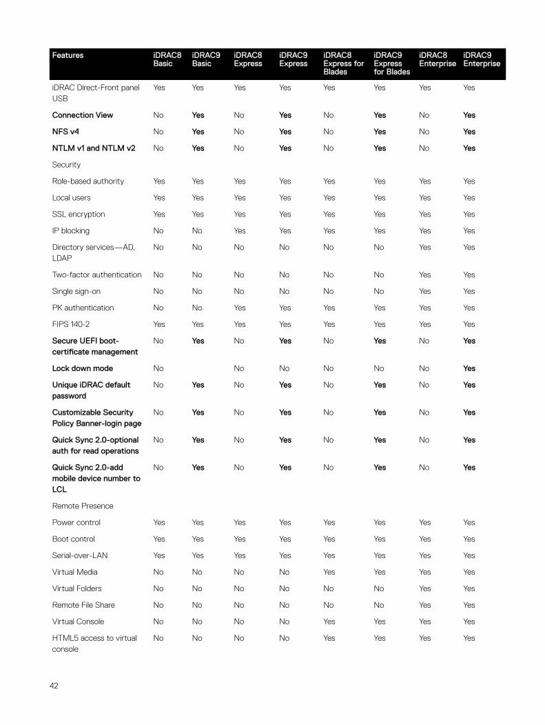
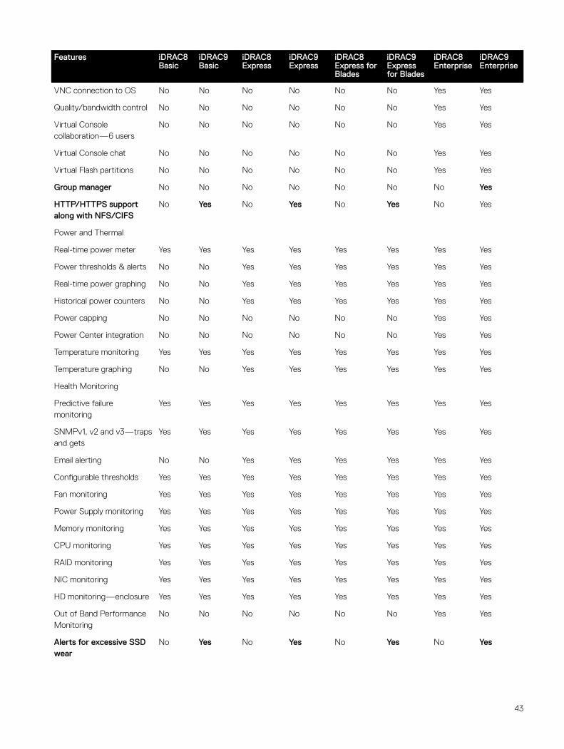
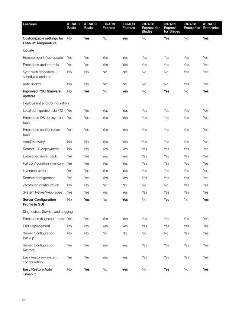
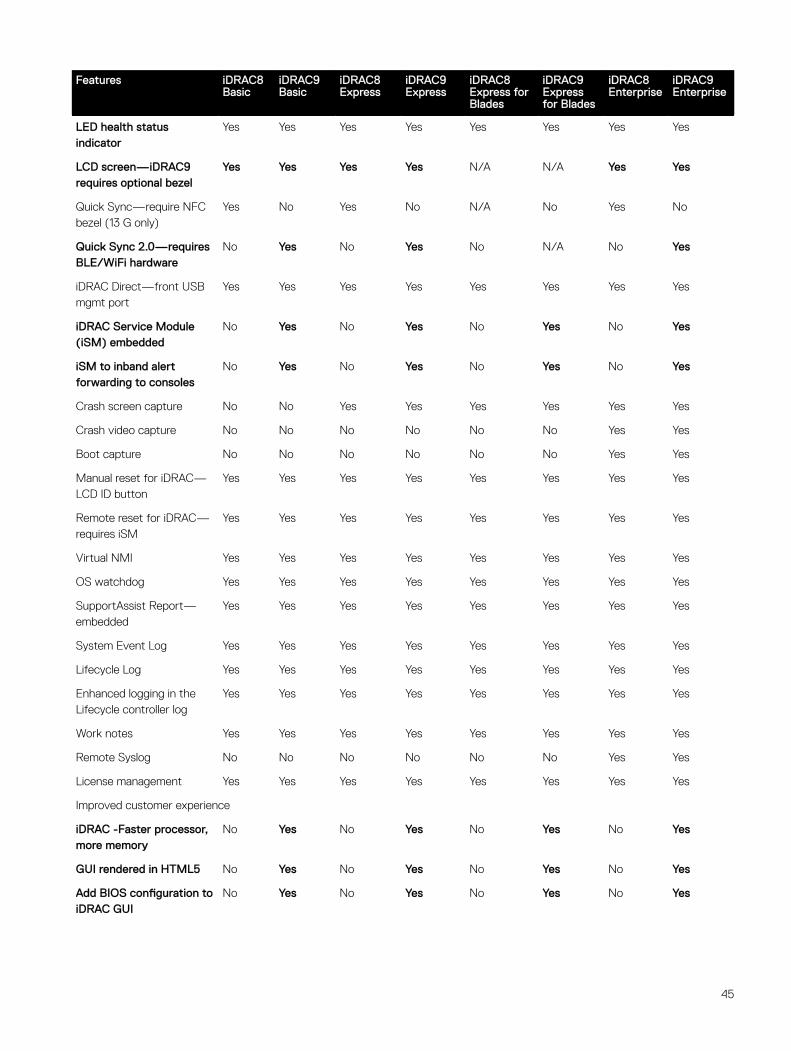
iDRAC features and comparison
The R840 supports the following iDRAC licenses – Basic (default), Express (upgrade) and Enterprise (upgrade).
NOTE: The features listed in bold in the below table are new for iDRAC9.
Table 14. iDRAC feature comparison
Features iDRAC8 Basic
iDRAC9 Basic
iDRAC8 Express
iDRAC9 Express
iDRAC8 Express for Blades
iDRAC9 Express for Blades
iDRAC8 Enterprise
iDRAC9 Enterprise
Interface/Standards
Redfish Yes Yes Yes Yes Yes Yes Yes Yes
IPMI 2.0 Yes Yes Yes Yes Yes Yes Yes Yes
DCMI 1.5 Yes Yes Yes Yes Yes Yes Yes Yes
Web-based GUI Yes Yes Yes Yes Yes Yes Yes Yes
Racadm command line—local/remote
Yes Yes Yes Yes Yes Yes Yes Yes
SMASH-CLP—SSH-only Yes Yes Yes Yes Yes Yes Yes Yes
Telnet Yes Yes Yes Yes Yes Yes Yes Yes
SSH Yes Yes Yes Yes Yes Yes Yes Yes
Serial redirection Yes Yes Yes Yes Yes Yes Yes Yes
WSMAN Yes Yes Yes Yes Yes Yes Yes Yes
Network Time Protocol No No Yes Yes Yes Yes Yes Yes
Connectivity
Shared NIC Yes Yes Yes Yes N/A N/A Yes Yes
Dedicated NIC Yes Yes Yes Yes Yes Yes Yes Yes
VLAN tagging Yes Yes Yes Yes Yes Yes Yes Yes
IPv4 Yes Yes Yes Yes Yes Yes Yes Yes
IPv6 Yes Yes Yes Yes Yes Yes Yes Yes
DHCP (new default; no static IP)
Yes Yes Yes Yes Yes Yes Yes Yes
DHCP with Zero Touch No No No No No No No Yes
Dynamic DNS Yes Yes Yes Yes Yes Yes Yes Yes
OS pass-through Yes Yes Yes Yes Yes Yes Yes Yes
41
Features iDRAC8 Basic
iDRAC9 Basic
iDRAC8 Express
iDRAC9 Express
iDRAC8 Express for Blades
iDRAC9 Express for Blades
iDRAC8 Enterprise
iDRAC9 Enterprise
iDRAC Direct-Front panel USB
Yes Yes Yes Yes Yes Yes Yes Yes
Connection View No Yes No Yes No Yes No Yes
NFS v4 No Yes No Yes No Yes No Yes
NTLM v1 and NTLM v2 No Yes No Yes No Yes No Yes
Security
Role-based authority Yes Yes Yes Yes Yes Yes Yes Yes
Local users Yes Yes Yes Yes Yes Yes Yes Yes
SSL encryption Yes Yes Yes Yes Yes Yes Yes Yes
IP blocking No No Yes Yes Yes Yes Yes Yes
Directory services—AD, LDAP
No No No No No No Yes Yes
Two-factor authentication No No No No No No Yes Yes
Single sign-on No No No No No No Yes Yes
PK authentication No No Yes Yes Yes Yes Yes Yes
FIPS 140-2 Yes Yes Yes Yes Yes Yes Yes Yes
Secure UEFI boot-certificate management
No Yes No Yes No Yes No Yes
Lock down mode No No No No No No Yes
Unique iDRAC default password
No Yes No Yes No Yes No Yes
Customizable Security Policy Banner-login page
No Yes No Yes No Yes No Yes
Quick Sync 2.0-optional auth for read operations
No Yes No Yes No Yes No Yes
Quick Sync 2.0-add mobile device number to LCL
No Yes No Yes No Yes No Yes
Remote Presence
Power control Yes Yes Yes Yes Yes Yes Yes Yes
Boot control Yes Yes Yes Yes Yes Yes Yes Yes
Serial-over-LAN Yes Yes Yes Yes Yes Yes Yes Yes
Virtual Media No No No No Yes Yes Yes Yes
Virtual Folders No No No No No No Yes Yes
Remote File Share No No No No No No Yes Yes
Virtual Console No No No No Yes Yes Yes Yes
HTML5 access to virtual console
No No No No Yes Yes Yes Yes
42
Features iDRAC8 Basic
iDRAC9 Basic
iDRAC8 Express
iDRAC9 Express
iDRAC8 Express for Blades
iDRAC9 Express for Blades
iDRAC8 Enterprise
iDRAC9 Enterprise
VNC connection to OS No No No No No No Yes Yes
Quality/bandwidth control No No No No No No Yes Yes
Virtual Console collaboration—6 users
No No No No No No Yes Yes
Virtual Console chat No No No No No No Yes Yes
Virtual Flash partitions No No No No No No Yes Yes
Group manager No No No No No No No Yes
HTTP/HTTPS support along with NFS/CIFS
No Yes No Yes No Yes No Yes
Power and Thermal
Real-time power meter Yes Yes Yes Yes Yes Yes Yes Yes
Power thresholds & alerts No No Yes Yes Yes Yes Yes Yes
Real-time power graphing No No Yes Yes Yes Yes Yes Yes
Historical power counters No No Yes Yes Yes Yes Yes Yes
Power capping No No No No No No Yes Yes
Power Center integration No No No No No No Yes Yes
Temperature monitoring Yes Yes Yes Yes Yes Yes Yes Yes
Temperature graphing No No Yes Yes Yes Yes Yes Yes
Health Monitoring
Predictive failure monitoring
Yes Yes Yes Yes Yes Yes Yes Yes
SNMPv1, v2 and v3—traps and gets
Yes Yes Yes Yes Yes Yes Yes Yes
Email alerting No No Yes Yes Yes Yes Yes Yes
Configurable thresholds Yes Yes Yes Yes Yes Yes Yes Yes
Fan monitoring Yes Yes Yes Yes Yes Yes Yes Yes
Power Supply monitoring Yes Yes Yes Yes Yes Yes Yes Yes
Memory monitoring Yes Yes Yes Yes Yes Yes Yes Yes
CPU monitoring Yes Yes Yes Yes Yes Yes Yes Yes
RAID monitoring Yes Yes Yes Yes Yes Yes Yes Yes
NIC monitoring Yes Yes Yes Yes Yes Yes Yes Yes
HD monitoring—enclosure Yes Yes Yes Yes Yes Yes Yes Yes
Out of Band Performance Monitoring
No No No No No No Yes Yes
Alerts for excessive SSD wear
No Yes No Yes No Yes No Yes
43
Features iDRAC8 Basic
iDRAC9 Basic
iDRAC8 Express
iDRAC9 Express
iDRAC8 Express for Blades
iDRAC9 Express for Blades
iDRAC8 Enterprise
iDRAC9 Enterprise
Customizable settings for Exhaust Temperature
No Yes No Yes No Yes No Yes
Update
Remote agent-free update Yes Yes Yes Yes Yes Yes Yes Yes
Embedded update tools Yes Yes Yes Yes Yes Yes Yes Yes
Sync with repository—scheduled updates
No No No No No No Yes Yes
Auto update No No No No No No Yes Yes
Improved PSU firmware updates
No Yes No Yes No Yes No Yes
Deployment and Configuration
Local configuration via F10 Yes Yes Yes Yes Yes Yes Yes Yes
Embedded OS deployment tools
Yes Yes Yes Yes Yes Yes Yes Yes
Embedded configuration tools
Yes Yes Yes Yes Yes Yes Yes Yes
AutoDiscovery No No Yes Yes Yes Yes Yes Yes
Remote OS deployment No No Yes Yes Yes Yes Yes Yes
Embedded driver pack Yes Yes Yes Yes Yes Yes Yes Yes
Full configuration inventory Yes Yes Yes Yes Yes Yes Yes Yes
Inventory export Yes Yes Yes Yes Yes Yes Yes Yes
Remote configuration Yes Yes Yes Yes Yes Yes Yes Yes
Zerotouch configuration No No No No No No Yes Yes
System Retire/Repurpose Yes Yes Yes Yes Yes Yes Yes Yes
Server Configuration Profile in GUI
No Yes No Yes No Yes No Yes
Diagnostics, Service and Logging
Embedded diagnostic tools Yes Yes Yes Yes Yes Yes Yes Yes
Part Replacement No No Yes Yes Yes Yes Yes Yes
Server Configuration Backup
No No No No No No Yes Yes
Server Configuration Restore
Yes Yes Yes Yes Yes Yes Yes Yes
Easy Restore—system configuration
Yes Yes Yes Yes Yes Yes Yes Yes
Easy Restore Auto Timeout
No Yes No Yes No Yes No Yes
44
Features iDRAC8 Basic
iDRAC9 Basic
iDRAC8 Express
iDRAC9 Express
iDRAC8 Express for Blades
iDRAC9 Express for Blades
iDRAC8 Enterprise
iDRAC9 Enterprise
LED health status indicator
Yes Yes Yes Yes Yes Yes Yes Yes
LCD screen—iDRAC9 requires optional bezel
Yes Yes Yes Yes N/A N/A Yes Yes
Quick Sync—require NFC bezel (13 G only)
Yes No Yes No N/A No Yes No
Quick Sync 2.0—requires BLE/WiFi hardware
No Yes No Yes No N/A No Yes
iDRAC Direct—front USB mgmt port
Yes Yes Yes Yes Yes Yes Yes Yes
iDRAC Service Module (iSM) embedded
No Yes No Yes No Yes No Yes
iSM to inband alert forwarding to consoles
No Yes No Yes No Yes No Yes
Crash screen capture No No Yes Yes Yes Yes Yes Yes
Crash video capture No No No No No No Yes Yes
Boot capture No No No No No No Yes Yes
Manual reset for iDRAC—LCD ID button
Yes Yes Yes Yes Yes Yes Yes Yes
Remote reset for iDRAC—requires iSM
Yes Yes Yes Yes Yes Yes Yes Yes
Virtual NMI Yes Yes Yes Yes Yes Yes Yes Yes
OS watchdog Yes Yes Yes Yes Yes Yes Yes Yes
SupportAssist Report—embedded
Yes Yes Yes Yes Yes Yes Yes Yes
System Event Log Yes Yes Yes Yes Yes Yes Yes Yes
Lifecycle Log Yes Yes Yes Yes Yes Yes Yes Yes
Enhanced logging in the Lifecycle controller log
Yes Yes Yes Yes Yes Yes Yes Yes
Work notes Yes Yes Yes Yes Yes Yes Yes Yes
Remote Syslog No No No No No No Yes Yes
License management Yes Yes Yes Yes Yes Yes Yes Yes
Improved customer experience
iDRAC -Faster processor, more memory
No Yes No Yes No Yes No Yes
GUI rendered in HTML5 No Yes No Yes No Yes No Yes
Add BIOS configuration to iDRAC GUI
No Yes No Yes No Yes No Yes
45
Features iDRAC8 Basic
iDRAC9 Basic
iDRAC8 Express
iDRAC9 Express
iDRAC8 Express for Blades
iDRAC9 Express for Blades
iDRAC8 Enterprise
iDRAC9 Enterprise
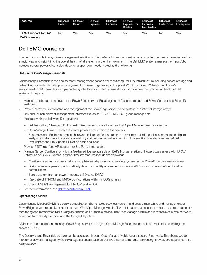
iDRAC support for SW RAID licensing
No Yes No Yes No Yes No Yes
Dell EMC consolesThe central console in a systems management solution is often referred to as the one-to-many console. The central console provides a rapid view and insight into the overall health of all systems in the IT environment. The Dell EMC systems management portfolio includes several powerful consoles, depending upon your needs, including the following:
Dell EMC OpenManage Essentials
OpenManage Essentials is the one-to-many management console for monitoring Dell HW infrastructure including server, storage and networking, as well as for lifecycle management of PowerEdge servers. It support Windows, Linux, VMware, and HyperV environments. OME provides a simple and easy interface for system administrators to maximize the uptime and health of Dell systems. It helps to
• Monitor health status and events for PowerEdge servers, EqualLogic or MD series storage, and PowerConnect and Force 10 switches.
• Provide hardware-level control and management for PowerEdge server, blade system, and internal storage arrays.
• Link and Launch element management interfaces, such as, iDRAC, CMC, EQL group manager etc
• Integrate with the following Dell solutions:
– Dell Repository Manager : Builds customized server update baselines that OpenManage Essentials can use.
– OpenManage Power Center : Optimize power consumption in the servers.
– SupportAssist : Enables automatic hardware failure notification to be sent securely to Dell technical support for intelligent analysis and diagnosis to optimize availability and reduce manual intervention. This solution is available as part of Dell ProSupport and ProSupport Plus at no additional cost.
• Provide REST interface API support for 3rd Party Integration.
• Manage Server Configuration - it is a fee-based license available on Dell’s 14th generation of PowerEdge servers with iDRAC Enterprise or iDRAC Express licenses. The key features include the following:
– Configure a server or chassis using a template and deploying an operating system on the PowerEdge bare metal servers.
– During a server operation, automatically detect and notify any server or chassis drift from a customer-defined baseline configuration.
– Boot a system from a network-mounted ISO using iDRAC.
– Replicate of FN-IOM and M-IOA configurations within M1000e chassis.
– Support VLAN Management for FN-IOM and M-IOA.
• For more information, see delltechcenter.com/OME
OpenManage Mobile
OpenManage Mobile(OMM) is a software application that enables easy, convenient, and secure monitoring and management of PowerEdge servers remotely, or at-the-server. With OpenManage Mobile, IT Administrators can securely perform several data center monitoring and remediation tasks using an Android or iOS mobile device. The OpenManage Mobile app is available as a free software download from the Apple Store and the Google Play Store.
OMM can also monitor and manage PowerEdge servers through a OpenManage Essentials console or by directly accessing the server’s iDRAC.
The OpenManage Essentials console can be accessed through OpenManage Mobile over a secure IP network. This allows you to monitor all devices managed by OpenManage Essentials such as Dell EMC servers, storage, networking, firewall, and supported third party devices.
46
If you are remote, you can access iDRAC over a secure IP network. If you are at-the-server, an iDRAC can be accessed directly by tapping an NFC-enabled android mobile device on a PowerEdge “Quick Sync” bezel to perform several basic bare-metal configuration tasks such as assigning an IP address, and changing server credentials or the boot order.
Key Features of OpenManage Mobile (When connected through OpenManage Essentials console):
• Connect to multiple servers which have OME installed, from a single mobile device.
• Connect to multiple servers individually through the iDRAC interface.
• Receive critical alert notification on your mobile device as they arrive into your OpenManage Essentials management console.
• Acknowledge, forward, and delete alerts from your mobile device.
• Browse through device details, firmware inventory, and event logs of individual systems.
• Perform several server management functions such as power-on, power cycle, reboot, and shutdown from the mobile application.
Key Features of OpenManage Mobile (When connected through iDRAC):
• Connect to any 14th gen, 13th gen, or 12th gen server remotely
• Access 14th gen rack or tower server through Quick Sync 2 module.
• Assign IP address, change credentials, and update common BIOS attributes for Bare Metal Configuration
• Configure one server manually, or multiple servers simultaneously through a template.
• Browse server details, health status, hardware & firmware inventory, networking details, and System Event or LC logs. Share this information easily with other IT Administrators.
• Access SupportAssist reports, Last Crash screen and video (PowerEdge 14th gen servers)
• Access Virtual Console (and reduce the need for crash carts).
• Power On, Shut down, or Reboot your server from anywhere.
• Run any RACADM command
OpenManage Power Center
OpenManage Power Center is a one-to-many application that can read power usage and thermal readings information from Dell EMC servers, Power Distribution Units (PDU), and Uninterruptible Power Supplies (UPS). It can aggregate this information into rack, row, and room-level views. On servers with iDRAC Enterprise license, you can also cap or throttle the power consumption. You may need to set power caps to reduce the power consumption due to external events such as brownouts or failures of data-center cooling devices. You can also use power capping to safely increase the numbers of servers in a rack to match the power that is provisioned for that rack.
For more information, see OpenManage Power Center User’s Guide available at Dell.com/openmanagemanuals.
Dell EMC OpenManage systems management tools, utilities and protocolsDell EMC OpenManage systems management tools and utilities consist of the following:
Dell EMC Repository Manager:
Dell EMC Repository Manager (DRM) is an application that helps you to:
• Identify the updates that are relevant to the systems in your data center.
• Identify and notify when updates are available.
• Package the updates into different deployment format.
To automate the creation of baseline repositories, DRM provides advanced integration capabilities with iDRAC/LC, OpenManage Essentials, Chassis Management Controller, OpenManage Integration for VMware vCenter and OpenManage Integration for Microsoft System Center (OMIMSSC). Also, DRM packages updates into custom catalogs that can be used for deployment.
47
Dell EMC Repository Manager can create the following deployment tools:
• Custom catalogs
• Lightweight deployment pack
• Bootable Linux ISO
• Custom Server Update Utility (SUU)
For more information, see Dell EMC Repository Manager User’s Guide available at Dell.com/support/manuals.
Dell Update Packages
Dell Update Packages (DUP) is a self-contained executable supported by Microsoft Windows or Linux that updates a component on a server and applications like OMSA, iSM, and DSET.
DUPs can be executed in GUI or in CLI mode.
For more information, see Dell EMC Update Packages User’s Guide available at www.delltechcenter.com/DSU.
Dell Remote Access Controller Administration (RACADM) CLI
The RACADM command-line utility provides a scriptable interface to perform inventory, configuration, update, and health status check of PowerEdge servers. RACADM operates in multiple modes:•
• Local — supports running RACADM commands from the managed server’s operating system.
• SSH or Telnet — known as Firmware RACADM; is accessible by logging in to iDRAC using SSH or Telnet
• Remote — supports running RACADM commands from a remote management station such as a laptop or desktop.
RACADM is supported by the iDRAC with Lifecycle Controller and by the Chassis Management Controller of the M1000e, VRTX and FX2 modular systems. Local and Remote RACADM is supported on Windows Server, Windows clients, and on Red Hat, SuSe and Ubuntu Linux.
For more information, see the RACADM Command Line Reference Guide for iDRAC and CMC available at Dell.com/support/manuals.
iDRAC with Lifecycle Controller Embedded Management APIs
iDRAC with Lifecycle Controller provides a range of standards-based applications programming interfaces (APIs) that enable scalable and automated management of PowerEdge servers. Standard systems management APIs have been developed by organizations such as the Institute of Electrical and Electronics Engineers (IEEE) and Distributed Management Task Force (DMTF). These APIs are widely used by commercial systems management products and by custom programs and scripts developed by IT staff to automate management functions such as discovery, inventory, health status checking, configuration, update, and power management. The APIs supported by iDRAC with Lifecycle Controller include:
• Redfish - In 2015, the DMTF Scalable Platforms Management Forum published Redfish, an open industry-standard specification and schema designed to meet the needs of IT administrators for simple, modern, and secure management of scalable platform hardware. Dell is a key contributor to the Redfish standard, acting as co-chair of the SPMF, promoting the benefits of Redfish, and working to deliver those benefits within industry-leading systems management solutions. Redfish is a next generation management standard using a data model representation inside a hypermedia RESTful interface. The data model is defined in terms of a standard, machine-readable schema, with the payload of the messages expressed in JSON and the OData v4 protocol.
• WSMan -The Web Services For Management (WSMan) API, first published by the DMTF in 2008, is the most mature and robust API provided by iDRAC with Lifecycle Controller. WSMan uses a Simple Object Access Protocol (SOAP) with data modeled using the Common Information Model. WSMan provides interoperability between management applications and managed resources, and identifies a core set of web service specifications and usage requirements that expose a common set of operations central to all systems management.
• IPMI - The Intelligent Platform Management Interface (IPMI) is a message-based, hardware-level interface specification that can operate over both LAN and serial interfaces. IPMI is supported broadly by server vendors, systems management solutions, and open source software.
• SNMP - The Simple Network Management Protocol (SNMP) helps in standardizing the management of network devices. SNMP allows commercial management consoles created for monitoring network switches and routers to also monitor X86
48
severs. SNMP is primarily used to deliver event messages to alert administrators of problems on their systems but can also be used to discover, inventory and configure servers.
To assist automating system management tasks and simplify API integration, Dell provides PowerShell and Python libraries and script examples utilizing the WSMan interface. The iDRAC with LC pages of Dell Techcenter offer a library of technical white papers detailing the use of the embedded management APIs. For more information, see delltechcenter.com/iDRAC and delltechcenter.com/LC.
Integration with third-party consolesDell EMC OpenManage provides integration with several leading third-party consoles, including:
OpenManage Integration Suite for Microsoft System Center
The combination of Dell OpenManage Integration Suite and Microsoft System Center simplifies and enhances deployment, configuration, monitoring and updating of Dell servers and storage in physical and virtual environments. Our agent-free and agent-based plug-ins deliver a unique level of integration and efficiency when managing Dell hardware within a System Center environment.
The OpenManage Integration Suite for Microsoft System Center includes: Dell Server and Storage Management Packs for System Center Operations Manager (SCOM); Dell Server Deployment Packs and Update Catalogs for System Center Configuration Manager (SCCM); and tools for optimizing management of Dell PowerEdge servers in virtual environments using System Center Virtual Machine Manager (SCVMM).
OpenManage Integration for VMware vCenter
The OpenManage Integration for VMware vCenter allows you to monitor, provision, and manage PowerEdge server hardware and firmware. You can perform these tasks through a dedicated Dell menu that can be accessed directly through the VMware vCenter console. OMIVV also allows granular control and reporting for the hardware environment using the same role-based access control model as vCenter. The OpenManage Management Pack for vRealize Operations Manager is available with OMIVV v4.0 onwards. This helps in checking hardware health and alerting into vRealize operations, which also includes dashboard and reporting on the server environment.
You can manage and monitor Dell hardware within the virtualized environment
• Alerting and monitoring environment for servers and chassis
• Monitoring and reporting for servers and chassis
• Updating firmware on servers
• Deploying enhanced options
For more information, see delltechcenter.com/omivv
NOTE: The Dell EMC Repository Manager integrates with OpenManage Integration for VMware vCenter. The Dell EMC Repository Manager provides advanced functionality, simplifies the discovery, and deployment of new updates.
BMC Software
Dell EMC and BMC Software work together to simplify IT by ensuring tight integration between Dell EMC server, storage, and network management functionality and the BMC Software process and data center automation products.
OpenManage connections with third-party consolesDell EMC OpenManage Connections gives you an easy path to adding support for third-party devices, so you can continue to use your existing management tools while easily adding Dell EMC server systems to your existing IT environment. Integrate new systems at your own pace. Manage new Dell EMC servers and storage with your legacy management tools, while extending the useful life of your existing resources. With OpenManage Connections you can add monitoring and troubleshooting of Dell EMC assets to your IT infrastructure.
49

• OpenManage Connection for Nagios Core and Nagios XI
• OpenManage Connection for HPE Operations Manager i (OMi)
For more information on these OpenManage Connections, visit Dell.com/openmanage.
50
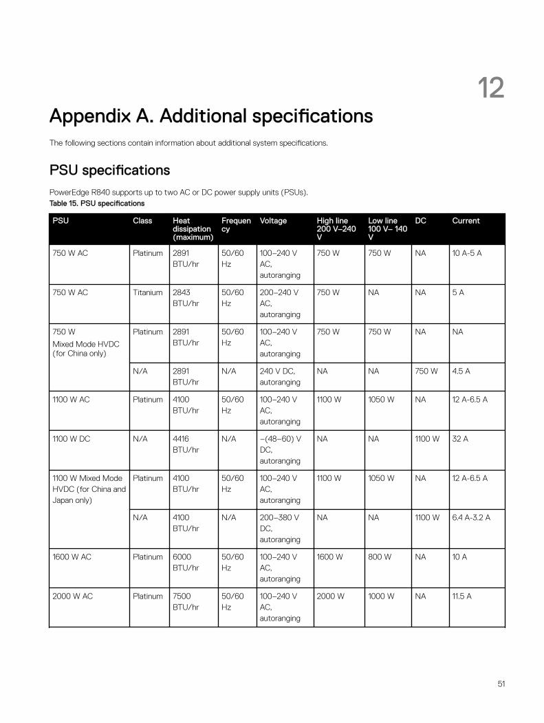
12Appendix A. Additional specificationsThe following sections contain information about additional system specifications.
PSU specificationsPowerEdge R840 supports up to two AC or DC power supply units (PSUs).Table 15. PSU specifications
PSU Class Heat dissipation (maximum)
Frequency
Voltage High line200 V–240 V
Low line100 V– 140 V
DC Current
750 W AC Platinum 2891 BTU/hr
50/60 Hz
100–240 V AC, autoranging
750 W 750 W NA 10 A-5 A
750 W AC Titanium 2843 BTU/hr
50/60 Hz
200–240 V AC, autoranging
750 W NA NA 5 A
750 W
Mixed Mode HVDC (for China only)
Platinum 2891 BTU/hr
50/60 Hz
100–240 V AC, autoranging
750 W 750 W NA NA
N/A 2891 BTU/hr
N/A 240 V DC, autoranging
NA NA 750 W 4.5 A
1100 W AC Platinum 4100 BTU/hr
50/60 Hz
100–240 V AC, autoranging
1100 W 1050 W NA 12 A-6.5 A
1100 W DC N/A 4416 BTU/hr
N/A –(48–60) V DC, autoranging
NA NA 1100 W 32 A
1100 W Mixed Mode HVDC (for China and Japan only)
Platinum 4100 BTU/hr
50/60 Hz
100–240 V AC, autoranging
1100 W 1050 W NA 12 A-6.5 A
N/A 4100 BTU/hr
N/A 200–380 V DC, autoranging
NA NA 1100 W 6.4 A-3.2 A
1600 W AC Platinum 6000 BTU/hr
50/60 Hz
100–240 V AC, autoranging
1600 W 800 W NA 10 A
2000 W AC Platinum 7500 BTU/hr
50/60 Hz
100–240 V AC, autoranging
2000 W 1000 W NA 11.5 A
51
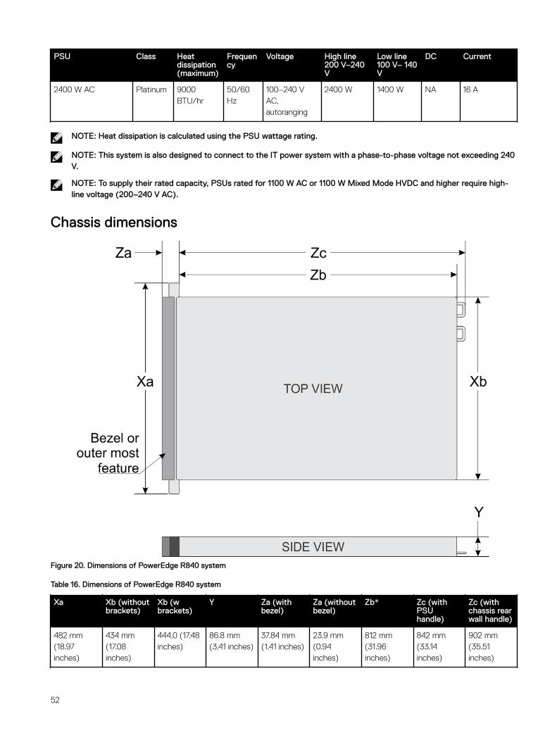
PSU Class Heat dissipation (maximum)
Frequency
Voltage High line200 V–240 V
Low line100 V– 140 V
DC Current
2400 W AC Platinum 9000 BTU/hr
50/60 Hz
100–240 V AC, autoranging
2400 W 1400 W NA 16 A
NOTE: Heat dissipation is calculated using the PSU wattage rating.
NOTE: This system is also designed to connect to the IT power system with a phase-to-phase voltage not exceeding 240 V.
NOTE: To supply their rated capacity, PSUs rated for 1100 W AC or 1100 W Mixed Mode HVDC and higher require high-line voltage (200–240 V AC).
Chassis dimensions
Figure 20. Dimensions of PowerEdge R840 system
Table 16. Dimensions of PowerEdge R840 system
Xa Xb (without brackets)
Xb (w brackets)
Y Za (with bezel)
Za (without bezel)
Zb* Zc (with PSU handle)
Zc (with chassis rear wall handle)
482 mm (18.97 inches)
434 mm (17.08 inches)
444.0 (17.48 inches)
86.8 mm (3.41 inches)
37.84 mm (1.41 inches)
23.9 mm (0.94 inches)
812 mm (31.96 inches)
842 mm (33.14 inches)
902 mm (35.51 inches)
52
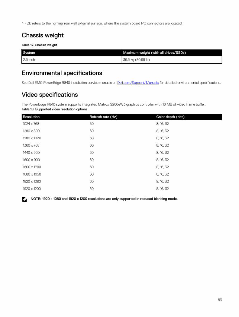
* - Zb refers to the nominal rear wall external surface, where the system board I/O connectors are located.
Chassis weightTable 17. Chassis weight
System Maximum weight (with all drives/SSDs)
2.5 inch 36.6 kg (80.68 lb)
Environmental specificationsSee Dell EMC PowerEdge R840 installation service manuals on Dell.com/Support/Manuals for detailed environmental specifications.
Video specificationsThe PowerEdge R840 system supports integrated Matrox G200eW3 graphics controller with 16 MB of video frame buffer.Table 18. Supported video resolution options
Resolution Refresh rate (Hz) Color depth (bits)
1024 x 768 60 8, 16, 32
1280 x 800 60 8, 16, 32
1280 x 1024 60 8, 16, 32
1360 x 768 60 8, 16, 32
1440 x 900 60 8, 16, 32
1600 x 900 60 8, 16, 32
1600 x 1200 60 8, 16, 32
1680 x 1050 60 8, 16, 32
1920 x 1080 60 8, 16, 32
1920 x 1200 60 8, 16, 32
NOTE: 1920 x 1080 and 1920 x 1200 resolutions are only supported in reduced blanking mode.
53
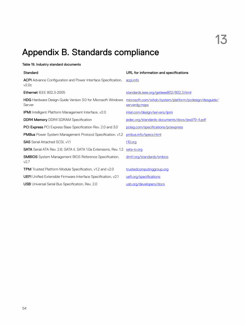
13Appendix B. Standards complianceTable 19. Industry standard documents
Standard URL for information and specifications
ACPI Advance Configuration and Power Interface Specification, v2.0c
acpi.info
Ethernet IEEE 802.3-2005 standards.ieee.org/getieee802/802.3.html
HDG Hardware Design Guide Version 3.0 for Microsoft Windows Server
microsoft.com/whdc/system/platform/pcdesign/desguide/serverdg.mspx
IPMI Intelligent Platform Management Interface, v2.0 intel.com/design/servers/ipmi
DDR4 Memory DDR4 SDRAM Specification jedec.org/standards-documents/docs/jesd79-4.pdf
PCI Express PCI Express Base Specification Rev. 2.0 and 3.0 pcisig.com/specifications/pciexpress
PMBus Power System Management Protocol Specification, v1.2 pmbus.info/specs.html
SAS Serial Attached SCSI, v1.1 t10.org
SATA Serial ATA Rev. 2.6; SATA II, SATA 1.0a Extensions, Rev. 1.2 sata-io.org
SMBIOS System Management BIOS Reference Specification, v2.7
dmtf.org/standards/smbios
TPM Trusted Platform Module Specification, v1.2 and v2.0 trustedcomputinggroup.org
UEFI Unified Extensible Firmware Interface Specification, v2.1 uefi.org/specifications
USB Universal Serial Bus Specification, Rev. 2.0 usb.org/developers/docs
54
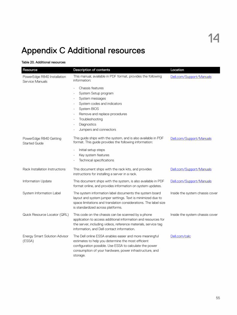
14Appendix C Additional resourcesTable 20. Additional resources
Resource Description of contents Location
PowerEdge R840 Installation Service Manuals
This manual, available in PDF format, provides the following information:
• Chassis features
• System Setup program
• System messages
• System codes and indicators
• System BIOS
• Remove and replace procedures
• Troubleshooting
• Diagnostics
• Jumpers and connectors
Dell.com/Support/Manuals
PowerEdge R840 Getting Started Guide
This guide ships with the system, and is also available in PDF format. This guide provides the following information:
• Initial setup steps
• Key system features
• Technical specifications
Dell.com/Support/Manuals
Rack Installation Instructions This document ships with the rack kits, and provides instructions for installing a server in a rack.
Dell.com/Support/Manuals
Information Update This document ships with the system, is also available in PDF format online, and provides information on system updates.
Dell.com/Support/Manuals
System Information Label The system information label documents the system board layout and system jumper settings. Text is minimized due to space limitations and translation considerations. The label size is standardized across platforms.
Inside the system chassis cover
Quick Resource Locator (QRL) This code on the chassis can be scanned by a phone application to access additional information and resources for the server, including videos, reference materials, service tag information, and Dell contact information.
Inside the system chassis cover
Energy Smart Solution Advisor (ESSA)
The Dell online ESSA enables easier and more meaningful estimates to help you determine the most efficient configuration possible. Use ESSA to calculate the power consumption of your hardware, power infrastructure, and storage.
Dell.com/calc
55
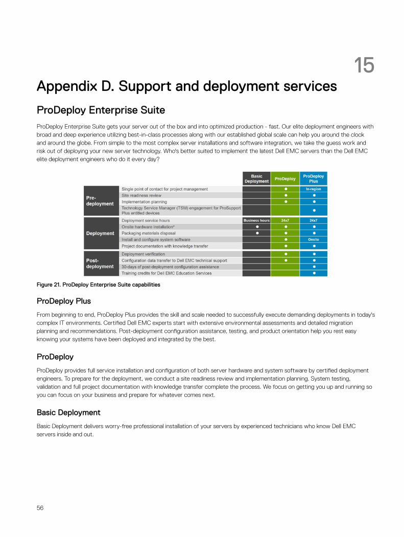
15Appendix D. Support and deployment services
ProDeploy Enterprise SuiteProDeploy Enterprise Suite gets your server out of the box and into optimized production - fast. Our elite deployment engineers with broad and deep experience utilizing best-in-class processes along with our established global scale can help you around the clock and around the globe. From simple to the most complex server installations and software integration, we take the guess work and risk out of deploying your new server technology. Who's better suited to implement the latest Dell EMC servers than the Dell EMC elite deployment engineers who do it every day?
Figure 21. ProDeploy Enterprise Suite capabilities
ProDeploy Plus
From beginning to end, ProDeploy Plus provides the skill and scale needed to successfully execute demanding deployments in today's complex IT environments. Certified Dell EMC experts start with extensive environmental assessments and detailed migration planning and recommendations. Post-deployment configuration assistance, testing, and product orientation help you rest easy knowing your systems have been deployed and integrated by the best.
ProDeploy
ProDeploy provides full service installation and configuration of both server hardware and system software by certified deployment engineers. To prepare for the deployment, we conduct a site readiness review and implementation planning. System testing, validation and full project documentation with knowledge transfer complete the process. We focus on getting you up and running so you can focus on your business and prepare for whatever comes next.
Basic Deployment
Basic Deployment delivers worry-free professional installation of your servers by experienced technicians who know Dell EMC servers inside and out.
56
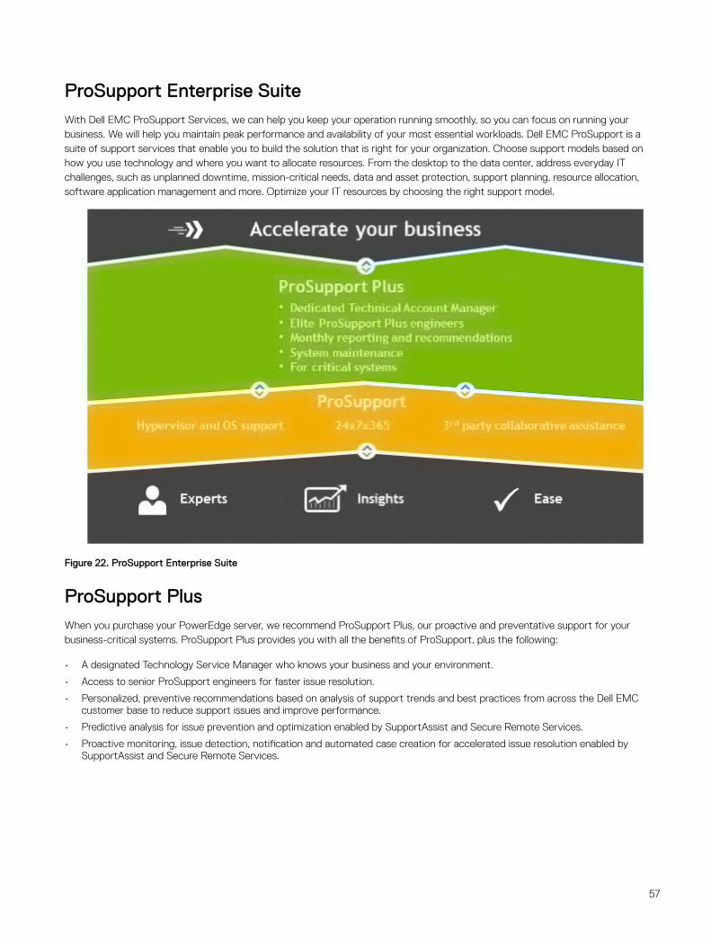
ProSupport Enterprise SuiteWith Dell EMC ProSupport Services, we can help you keep your operation running smoothly, so you can focus on running your business. We will help you maintain peak performance and availability of your most essential workloads. Dell EMC ProSupport is a suite of support services that enable you to build the solution that is right for your organization. Choose support models based on how you use technology and where you want to allocate resources. From the desktop to the data center, address everyday IT challenges, such as unplanned downtime, mission-critical needs, data and asset protection, support planning, resource allocation, software application management and more. Optimize your IT resources by choosing the right support model.
Figure 22. ProSupport Enterprise Suite
ProSupport PlusWhen you purchase your PowerEdge server, we recommend ProSupport Plus, our proactive and preventative support for your business-critical systems. ProSupport Plus provides you with all the benefits of ProSupport, plus the following:
• A designated Technology Service Manager who knows your business and your environment.
• Access to senior ProSupport engineers for faster issue resolution.
• Personalized, preventive recommendations based on analysis of support trends and best practices from across the Dell EMC customer base to reduce support issues and improve performance.
• Predictive analysis for issue prevention and optimization enabled by SupportAssist and Secure Remote Services.
• Proactive monitoring, issue detection, notification and automated case creation for accelerated issue resolution enabled by SupportAssist and Secure Remote Services.
57
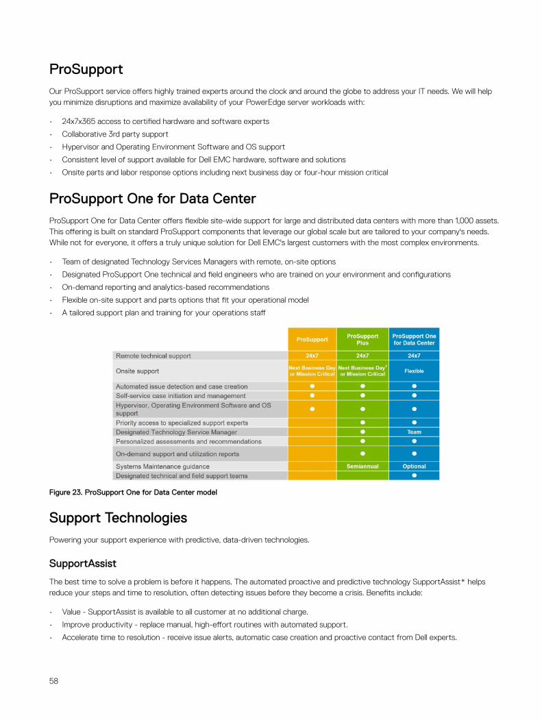
ProSupportOur ProSupport service offers highly trained experts around the clock and around the globe to address your IT needs. We will help you minimize disruptions and maximize availability of your PowerEdge server workloads with:
• 24x7x365 access to certified hardware and software experts
• Collaborative 3rd party support
• Hypervisor and Operating Environment Software and OS support
• Consistent level of support available for Dell EMC hardware, software and solutions
• Onsite parts and labor response options including next business day or four-hour mission critical
ProSupport One for Data CenterProSupport One for Data Center offers flexible site-wide support for large and distributed data centers with more than 1,000 assets. This offering is built on standard ProSupport components that leverage our global scale but are tailored to your company's needs. While not for everyone, it offers a truly unique solution for Dell EMC's largest customers with the most complex environments.
• Team of designated Technology Services Managers with remote, on-site options
• Designated ProSupport One technical and field engineers who are trained on your environment and configurations
• On-demand reporting and analytics-based recommendations
• Flexible on-site support and parts options that fit your operational model
• A tailored support plan and training for your operations staff
Figure 23. ProSupport One for Data Center model
Support TechnologiesPowering your support experience with predictive, data-driven technologies.
SupportAssist
The best time to solve a problem is before it happens. The automated proactive and predictive technology SupportAssist* helps reduce your steps and time to resolution, often detecting issues before they become a crisis. Benefits include:
• Value - SupportAssist is available to all customer at no additional charge.
• Improve productivity - replace manual, high-effort routines with automated support.
• Accelerate time to resolution - receive issue alerts, automatic case creation and proactive contact from Dell experts.
58
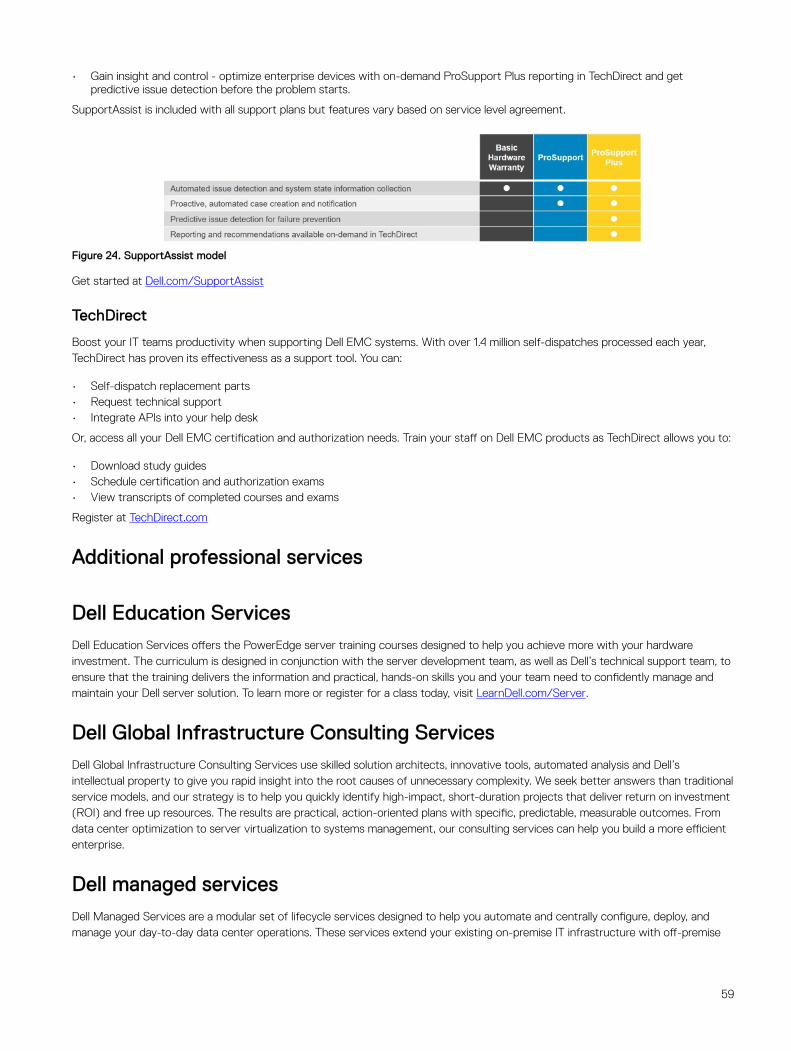
• Gain insight and control - optimize enterprise devices with on-demand ProSupport Plus reporting in TechDirect and get predictive issue detection before the problem starts.
SupportAssist is included with all support plans but features vary based on service level agreement.
Figure 24. SupportAssist model
Get started at Dell.com/SupportAssist
TechDirect
Boost your IT teams productivity when supporting Dell EMC systems. With over 1.4 million self-dispatches processed each year, TechDirect has proven its effectiveness as a support tool. You can:
• Self-dispatch replacement parts• Request technical support• Integrate APIs into your help desk
Or, access all your Dell EMC certification and authorization needs. Train your staff on Dell EMC products as TechDirect allows you to:
• Download study guides• Schedule certification and authorization exams• View transcripts of completed courses and exams
Register at TechDirect.com
Additional professional services
Dell Education ServicesDell Education Services offers the PowerEdge server training courses designed to help you achieve more with your hardware investment. The curriculum is designed in conjunction with the server development team, as well as Dell’s technical support team, to ensure that the training delivers the information and practical, hands-on skills you and your team need to confidently manage and maintain your Dell server solution. To learn more or register for a class today, visit LearnDell.com/Server.
Dell Global Infrastructure Consulting ServicesDell Global Infrastructure Consulting Services use skilled solution architects, innovative tools, automated analysis and Dell’s intellectual property to give you rapid insight into the root causes of unnecessary complexity. We seek better answers than traditional service models, and our strategy is to help you quickly identify high-impact, short-duration projects that deliver return on investment (ROI) and free up resources. The results are practical, action-oriented plans with specific, predictable, measurable outcomes. From data center optimization to server virtualization to systems management, our consulting services can help you build a more efficient enterprise.
Dell managed servicesDell Managed Services are a modular set of lifecycle services designed to help you automate and centrally configure, deploy, and manage your day-to-day data center operations. These services extend your existing on-premise IT infrastructure with off-premise
59

cloud services designed to better address challenges with mobility, highly distributed organizations, security, compliance, business continuity, and disaster preparedness.
60