Embed Size (px)
Citation preview
Dell PowerEdge C Servers Data Analytics Solution
Reference Architecture and Best Practices
Dell │ Greenplum
Release A0
September 2010
Dell | Greenplum Database Solution | Reference Architecture and Best Practices
Page ii
© 2010 Dell Inc. All rights reserved. Reproduction of this material in any manner whatsoever without
the express written permission of Dell Inc. is strictly forbidden. For more information, contact Dell.
Dell, the DELL logo, and the DELL badge, PowerConnect, and PowerVault are trademarks of Dell Inc.
Microsoft, Windows, Windows Server, and Active Directory are either trademarks or registered
trademarks of Microsoft Corporation in the United States and/or other countries. Other trademarks and
trade names may be used in this document to refer to either the entities claiming the marks and names
or their products. Dell Inc. disclaims any proprietary interest in trademarks and trade names other than
its own.
August 2010
Dell | Greenplum Database Solution | Reference Architecture and Best Practices
Page 1
CONTENTS 1 OVERVIEW .......................................................................................................................................................... 2
1.1 SUMMARY ............................................................................................................................................................... 2
1.2 ACRONYMS .............................................................................................................................................................. 2
2 SOLUTION ARCHITECTURE, PACKAGING, AND DELIVERY ..................................................................................... 3
2.1 HIGH-LEVEL SOLUTION ARCHITECTURE .......................................................................................................................... 3
2.2 SOLUTION PACKAGING AND DELIVERY ........................................................................................................................... 6
3 NETWORK ARCHITECTURE .................................................................................................................................. 9
4 BEST PRACTICES FOR CONSTRUCTING THE SOLUTION ....................................................................................... 10
4.1 GENERAL CONSIDERATIONS ...................................................................................................................................... 10
4.2 HOW TO BUILD A POC SOLUTION .............................................................................................................................. 10
4.3 HOW TO BUILD A PRODUCTION SOLUTION ................................................................................................................... 11
4.4 RACK POWER OPTIONS ............................................................................................................................................ 12
4.5 RACK PLUG LOCATION ............................................................................................................................................. 12
4.6 SWITCH / PANEL LOCATION ...................................................................................................................................... 13
4.7 SEGMENT/ETL NODE DISK OPTIONS .......................................................................................................................... 13
4.8 ETL OPTION .......................................................................................................................................................... 13
Dell | Greenplum Database Solution | Reference Architecture and Best Practices
Page 2
1 Overview
1.1 Summary The document presents the reference architecture of an ISV-type implementation of Greenplum’s
Analytics Solution that Dell will market jointly with Greenplum.
The reference architecture introduces all the high-level components, hardware, and software that are
included in the stack. Each high-level component is then described individually.
1.2 Acronyms
Acronym Definition
PDU POWER DISTRIBUTION UNIT
BMC BASEBOARD MANAGEMENT CONTROLLER
Dell | Greenplum Database Solution | Reference Architecture and Best Practices
Page 3
2 Solution Architecture, Packaging, and Delivery
2.1 High-level Solution Architecture The Greenplum stack contains both hardware and software components.
The software component is Greenplum Database 4.0, a major release of Greenplum’s industry-leading
massively parallel processing (MPP) database product. The Greenplum Database architecture provides
automatic parallelization of data and queries—all data is automatically partitioned across all nodes of
the system, and queries are planned and executed using all nodes working together in a highly
coordinated fashion. The Database utilizes multiple levels of fault tolerance and redundancy that allow
it to automatically continue operation in the face of hardware or software failures. The Database is
designed to automatically expand by adding servers to increase storage capacity, processing
performance, and loading performance.
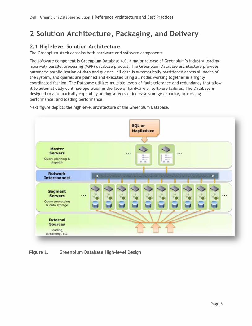
Next figure depicts the high-level architecture of the Greenplum Database.
Figure 1. Greenplum Database High-level Design
Dell | Greenplum Database Solution | Reference Architecture and Best Practices
Page 4
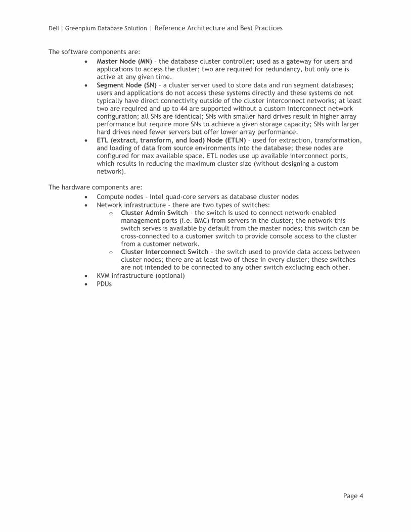
The software components are:
Master Node (MN) – the database cluster controller; used as a gateway for users and applications to access the cluster; two are required for redundancy, but only one is active at any given time.
Segment Node (SN) – a cluster server used to store data and run segment databases; users and applications do not access these systems directly and these systems do not typically have direct connectivity outside of the cluster interconnect networks; at least two are required and up to 44 are supported without a custom interconnect network configuration; all SNs are identical; SNs with smaller hard drives result in higher array performance but require more SNs to achieve a given storage capacity; SNs with larger hard drives need fewer servers but offer lower array performance.
ETL (extract, transform, and load) Node (ETLN) – used for extraction, transformation, and loading of data from source environments into the database; these nodes are configured for max available space. ETL nodes use up available interconnect ports, which results in reducing the maximum cluster size (without designing a custom network).
The hardware components are:
Compute nodes – Intel quad-core servers as database cluster nodes
Network infrastructure – there are two types of switches: o Cluster Admin Switch – the switch is used to connect network-enabled
management ports (i.e. BMC) from servers in the cluster; the network this switch serves is available by default from the master nodes; this switch can be cross-connected to a customer switch to provide console access to the cluster from a customer network.
o Cluster Interconnect Switch – the switch used to provide data access between cluster nodes; there are at least two of these in every cluster; these switches are not intended to be connected to any other switch excluding each other.
KVM infrastructure (optional)
PDUs
Dell | Greenplum Database Solution | Reference Architecture and Best Practices
Page 5
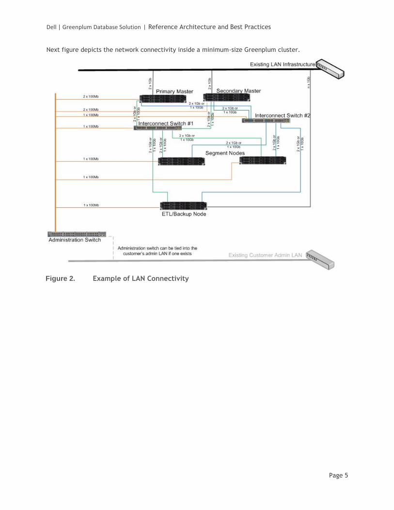
Next figure depicts the network connectivity inside a minimum-size Greenplum cluster.
Figure 2. Example of LAN Connectivity
Dell | Greenplum Database Solution | Reference Architecture and Best Practices
Page 6
2.2 Solution Packaging and Delivery Packaging and delivering the Dell/Greenplum solution must address the following use cases:
1. Proof-of-Concept (POC): a customer needs to test-drive the product; this will require a minimal configuration (hardware and software) to be hosted at the customer (or a third-party site). The customer, the vendor, or both will define the configuration—it can be anywhere from four servers to 20 servers.
2. Production: a customer wants to run the application in its production environment; this can be a much larger scale configuration but will typically be 20 to 200 servers.
3. Migration from POC to Production: a customer wants to migrate the POC to a production configuration. This can be done by adding new nodes/racks, although there may be cases when no new hardware is required.
The solution building blocks (SKUs) are:
MASTER_SKU – one PowerEdge C2100 machine running the Master Node software. Up to two MASTER_SKU nodes are supported in a single cluster.
SEGMENT_SKU – a pair of PowerEdge C2100 machines running the Segment Node software. Up to 22 pairs (44 nodes total) can be added to the cluster without designing a custom interconnect network.
ETLN_SKU – one PowerEdge C2100 machine running the ETL Node software
INTERCONNECT_SWITCH_SKU – a pair of PowerConnect 6248 switches. A single pair of switches can support 20 segment nodes. Two pairs of PowerConnect 6248s can support up to 44 segment nodes. These switches are used for the database interconnect traffic.
ADMIN_SWITCH_SKU – one 48-port GigE switch, i.e. PowerConnect 5448. This switch connects all the BMC NICs in the cluster.
KVM_SKU – a 16-port digital KVM appliance
42U_RACK_SKU – one 42U rack
PDU_SKU – pair of single phase 208V/30A metered PDUs. A minimum of two PDUs are required per rack, although four are recommended for full fault tolerance.
Dell | Greenplum Database Solution | Reference Architecture and Best Practices
Page 7
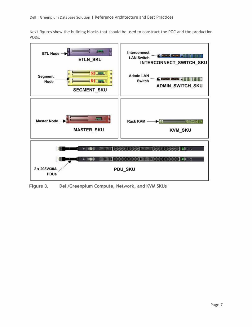
Next figures show the building blocks that should be used to construct the POC and the production
PODs.
Figure 3. Dell/Greenplum Compute, Network, and KVM SKUs
Dell | Greenplum Database Solution | Reference Architecture and Best Practices
Page 8
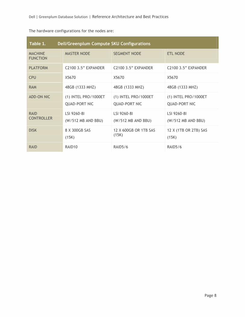
The hardware configurations for the nodes are:
Table 1. Dell/Greenplum Compute SKU Configurations
MACHINE FUNCTION
MASTER NODE SEGMENT NODE ETL NODE
PLATFORM C2100 3.5” EXPANDER C2100 3.5” EXPANDER C2100 3.5” EXPANDER
CPU X5670 X5670 X5670
RAM 48GB (1333 MHZ) 48GB (1333 MHZ) 48GB (1333 MHZ)
ADD-ON NIC (1) INTEL PRO/1000ET
QUAD-PORT NIC
(1) INTEL PRO/1000ET
QUAD-PORT NIC
(1) INTEL PRO/1000ET
QUAD-PORT NIC
RAID CONTROLLER
LSI 9260-8I
(W/512 MB AND BBU)
LSI 9260-8I
(W/512 MB AND BBU)
LSI 9260-8I
(W/512 MB AND BBU)
DISK 8 X 300GB SAS
(15K)
12 X 600GB OR 1TB SAS (15K)
12 X (1TB OR 2TB) SAS
(15K)
RAID RAID10 RAID5/6 RAID5/6
Dell | Greenplum Database Solution | Reference Architecture and Best Practices
Page 9
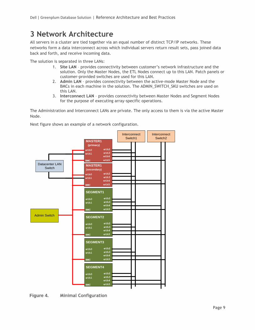
3 Network Architecture All servers in a cluster are tied together via an equal number of distinct TCP/IP networks. These
networks form a data interconnect across which individual servers return result sets, pass joined data
back and forth, and receive incoming data.
The solution is separated in three LANs:
1. Site LAN – provides connectivity between customer’s network infrastructure and the solution. Only the Master Nodes, the ETL Nodes connect up to this LAN. Patch panels or customer-provided switches are used for this LAN.
2. Admin LAN – provides connectivity between the active-mode Master Node and the BMCs in each machine in the solution. The ADMIN_SWITCH_SKU switches are used on this LAN.
3. Interconnect LAN – provides connectivity between Master Nodes and Segment Nodes for the purpose of executing array-specific operations.
The Administration and Interconnect LANs are private. The only access to them is via the active Master
Node.
Next figure shows an example of a network configuration.
Admin Switch
SEGMENT1
eth0
eth1
BMC
eth4
eth5
eth2
eth3
SEGMENT2
eth0
eth1
BMC
eth4
eth5
eth2
eth3
SEGMENT3
eth0
eth1
BMC
eth4
eth5
eth2
eth3
SEGMENT4
eth0
eth1
BMC
eth4
eth5
eth2
eth3
Datacenter LAN
Switch
MASTER1
(primary)
eth0
eth1
BMC
eth4
eth5
BMC
eth2
eth3
MASTER1
(secondary)
eth0
eth1
BMC
eth4
eth5
eth2
eth3
Interconnect
Switch1
Interconnect
Switch2
Figure 4. Minimal Configuration
Dell | Greenplum Database Solution | Reference Architecture and Best Practices
Page 10
4 Best Practices for Constructing the Solution
4.1 General Considerations The following guidelines apply to any implementation of the Dell/Greenplum Database solution:
1. The number of servers installed in a rack depends on: a. Available ports in top-of-rack switches b. Available power per rack (aka rack power envelope) c. Available space in the rack
2. For redundancy reasons the four installed NICs should be spread across the available interconnect switches in a consistent manner. For example, in a 20 node cluster with two interconnect switches, you would wire ports 1 and 3 to the first interconnect switch and port 2 and 4 to the second interconnect switch. In the case of a cluster with 40 nodes and four interconnect switches, you would connect port 1 to switch 1, port 2 to switch 2, and so forth.
3. The ETL Nodes are optional. 4. A solution designed for production must include two MASTER nodes—one will be active,
the second one will be in standby. A solution designed for a proof-of-concept might not require redundant MASTER nodes.
5. Switches installed in the same rack should NOT be trunked or connected together.
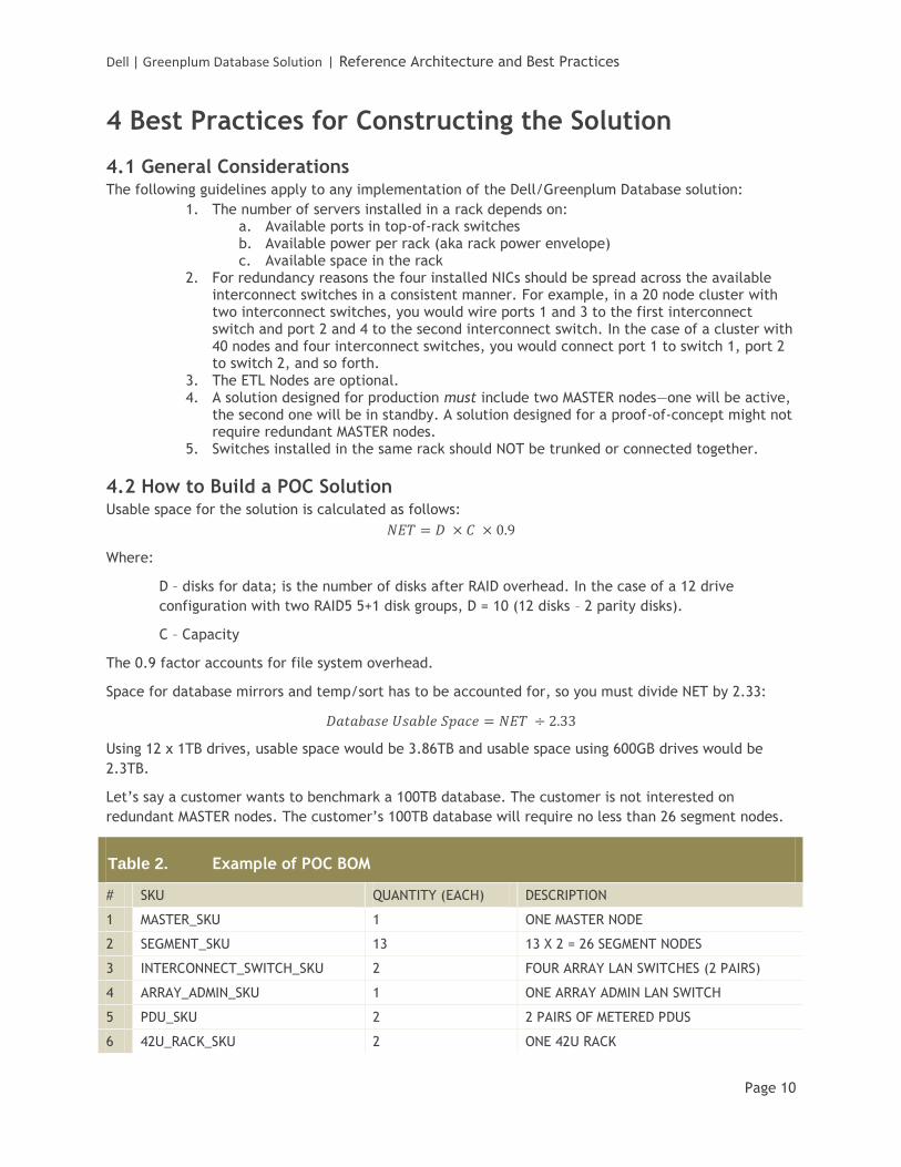
4.2 How to Build a POC Solution Usable space for the solution is calculated as follows:
Where:
D – disks for data; is the number of disks after RAID overhead. In the case of a 12 drive
configuration with two RAID5 5+1 disk groups, D = 10 (12 disks – 2 parity disks).
C – Capacity
The 0.9 factor accounts for file system overhead.
Space for database mirrors and temp/sort has to be accounted for, so you must divide NET by 2.33:
Using 12 x 1TB drives, usable space would be 3.86TB and usable space using 600GB drives would be
2.3TB.
Let’s say a customer wants to benchmark a 100TB database. The customer is not interested on
redundant MASTER nodes. The customer’s 100TB database will require no less than 26 segment nodes.
Table 2. Example of POC BOM
# SKU QUANTITY (EACH) DESCRIPTION
1 MASTER_SKU 1 ONE MASTER NODE
2 SEGMENT_SKU 13 13 X 2 = 26 SEGMENT NODES
3 INTERCONNECT_SWITCH_SKU 2 FOUR ARRAY LAN SWITCHES (2 PAIRS)
4 ARRAY_ADMIN_SKU 1 ONE ARRAY ADMIN LAN SWITCH
5 PDU_SKU 2 2 PAIRS OF METERED PDUS
6 42U_RACK_SKU 2 ONE 42U RACK
Dell | Greenplum Database Solution | Reference Architecture and Best Practices
Page 11
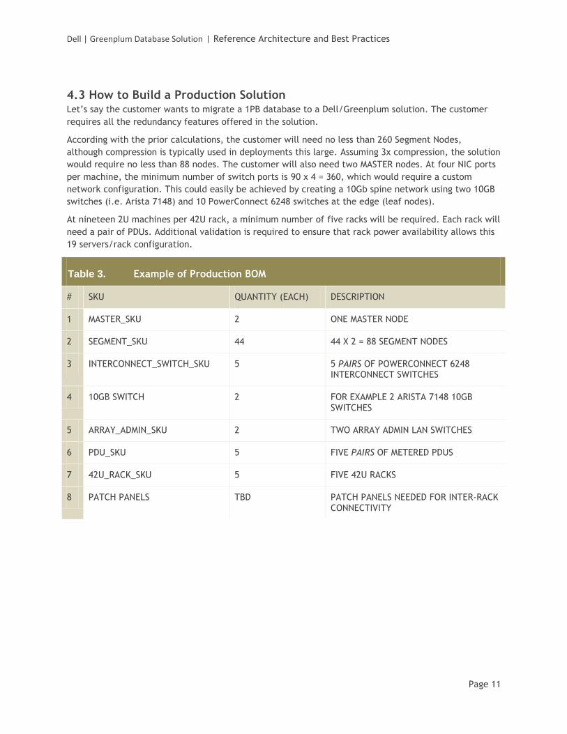
4.3 How to Build a Production Solution Let’s say the customer wants to migrate a 1PB database to a Dell/Greenplum solution. The customer
requires all the redundancy features offered in the solution.
According with the prior calculations, the customer will need no less than 260 Segment Nodes,
although compression is typically used in deployments this large. Assuming 3x compression, the solution
would require no less than 88 nodes. The customer will also need two MASTER nodes. At four NIC ports
per machine, the minimum number of switch ports is 90 x 4 = 360, which would require a custom
network configuration. This could easily be achieved by creating a 10Gb spine network using two 10GB
switches (i.e. Arista 7148) and 10 PowerConnect 6248 switches at the edge (leaf nodes).
At nineteen 2U machines per 42U rack, a minimum number of five racks will be required. Each rack will
need a pair of PDUs. Additional validation is required to ensure that rack power availability allows this
19 servers/rack configuration.
Table 3. Example of Production BOM
# SKU QUANTITY (EACH) DESCRIPTION
1 MASTER_SKU 2 ONE MASTER NODE
2 SEGMENT_SKU 44 44 X 2 = 88 SEGMENT NODES
3 INTERCONNECT_SWITCH_SKU 5 5 PAIRS OF POWERCONNECT 6248 INTERCONNECT SWITCHES
4 10GB SWITCH 2 FOR EXAMPLE 2 ARISTA 7148 10GB SWITCHES
5 ARRAY_ADMIN_SKU 2 TWO ARRAY ADMIN LAN SWITCHES
6 PDU_SKU 5 FIVE PAIRS OF METERED PDUS
7 42U_RACK_SKU 5 FIVE 42U RACKS
8 PATCH PANELS TBD PATCH PANELS NEEDED FOR INTER-RACK CONNECTIVITY
Dell | Greenplum Database Solution | Reference Architecture and Best Practices
Page 12
4.4 Rack Power Options There are two rack power options, single-phase or three-phase power circuits. Each of these options is
implemented differently depending on region.
4.4.1 Single-Phase Power
Default Option
Single-phase-powered racks are the default option. Due to various regional certification issues,
there are significant differences between the North American and the European or Asian
clusters.
4.4.1.1 North America
The North American rack uses four, 30Amp, 208Volt power distribution units (PDUs). Each of
these PDUs has a twist-lock, L6-30P, 3-prong plug.
4.4.1.2 International
The European and Asian single-phase rack uses four, 32Amp, 230Volt PDUs. All of these PDUs
use IEC309, 3-prong (2P+E) plugs.
4.4.2 Three-Phase Power
Three-phase racks have two, 3-phase power distribution units each. Each rack requires two, 3-
phase circuits. The specific voltage, amperage, and plug interfaces vary by region.
4.4.2.1 North America
These racks require two, 3-phase circuits each delivering 208Volt/30Amp each. The racks use
two CS8365, 4-prong, high voltage plugs.
4.4.2.2 International
These racks require two 3-phase circuits delivering 400Volt/32Amp each. The racks use two
IEC60309 3P+N+E, 5-prong plugs.
4.5 Rack Plug Location
4.5.1 Bottom
Default Option
Rack plugs extend through the bottom of the rack. This is the default option.
4.5.2 Top
Rack plugs extend through the top of the rack and must be specified as an option.
Dell | Greenplum Database Solution | Reference Architecture and Best Practices
Page 13
4.6 Switch / Panel Location Only clusters requiring more than one rack have an option for locating switches and patch panels in the
bottom. Clusters that ship in a single rack always have top-mounted switches and patch panels. All
racks in a multi-rack cluster will be configured the same way unless specifically indicated on the order.
4.6.1 Top
Default Option
Switches and patch panels installed in the top of the rack. This is the default option.
4.6.2 Bottom
Switches and patch panels installed in the bottom of the rack. This option must be
requested. This cannot be requested for single-rack clusters.
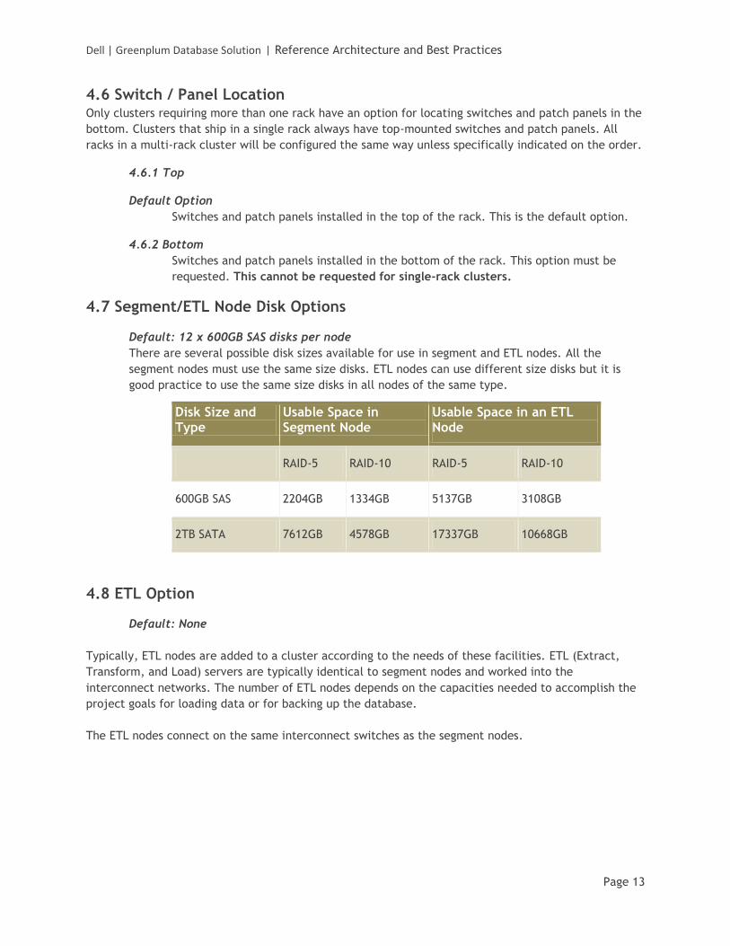
4.7 Segment/ETL Node Disk Options
Default: 12 x 600GB SAS disks per node
There are several possible disk sizes available for use in segment and ETL nodes. All the
segment nodes must use the same size disks. ETL nodes can use different size disks but it is
good practice to use the same size disks in all nodes of the same type.
Disk Size and Type
Usable Space in Segment Node
Usable Space in an ETL Node
RAID-5 RAID-10 RAID-5 RAID-10
600GB SAS 2204GB 1334GB 5137GB 3108GB
2TB SATA 7612GB 4578GB 17337GB 10668GB
4.8 ETL Option
Default: None
Typically, ETL nodes are added to a cluster according to the needs of these facilities. ETL (Extract,
Transform, and Load) servers are typically identical to segment nodes and worked into the
interconnect networks. The number of ETL nodes depends on the capacities needed to accomplish the
project goals for loading data or for backing up the database.
The ETL nodes connect on the same interconnect switches as the segment nodes.