Embed Size (px)
Citation preview
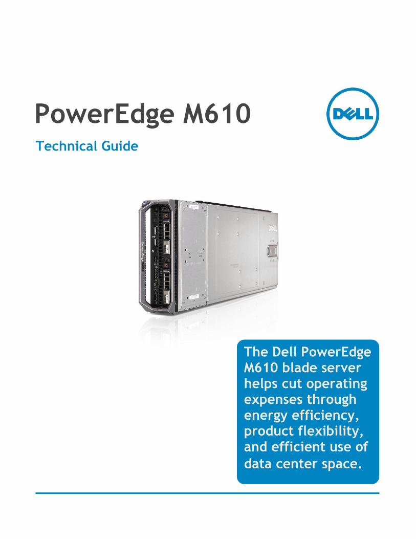
PowerEdge M610 Technical Guide
The Dell PowerEdge M610 blade server helps cut operating expenses through energy efficiency, product flexibility, and efficient use of
data center space.
Dell
Dell PowerEdge M610 Technical Guide ii
Dell, PowerEdge, EqualLogic, PowerVault, OpenManage, and ReadyRails are trademarks of Dell, Inc. Citrix and XenServer are registered trademarks of Citrix Systems, Inc. and/or one or more of its subsidiaries, and may be registered in the United States Patent and Trademark Office and in other countries. Intel, Xeon, and Speedstep are registered trademarks and MMX and Core are trademarks of Intel Corporation in the U.S. and other countries. Broadcom is a registered trademark and NetXtreme is a trademark of Broadcom Corporation and/or its affiliates in the United States, certain other countries and/or the EU. InfiniBand is a registered trademark and service mark of the InfiniBand Trade Association. Matrox is a registered trademark of Matrox Electronic Systems Ltd. Microsoft, Windows, Windows Server, SQL Server, and BitLocker, and Hyper-V are either registered trademarks or trademarks of Microsoft Corporation in the United States and/or other countries. Mellanox and ConnectX are registered trademarks of Mellanox Technologies, Inc. Novell and SUSE are registered trademarks of Novell, Inc. in the United States and other countries. PCI Express is a registered trademark of PCI-SIG. Red Hat is a registered trademark of Red Hat, Inc. in the United States and other countries. Linux is a registered trademark of Linus Torvalds. NVIDIA is a registered trademark and Tesla is a trademark of NVIDIA Corporation in the U.S. and other countries. QLogic is a registered trademark of QLogic Corporation. VMware and VSphere are registered trademarks and ESX and ESXi are trademarks of VMware, Inc. in the United States and/or other jurisdictions. Other trademarks and trade names may be used in this document to refer to either the entities claiming the marks and names or their products. Dell disclaims proprietary interest in the marks and names of others.
©Copyright 2012 Dell Inc. All rights reserved. Reproduction or translation of any part of this work beyond that permitted by U.S. copyright laws without the written permission of Dell Inc. is unlawful and strictly forbidden.
December 2012 | Version 4.0
Dell
Dell PowerEdge M610 Technical Guide iii
Table of Contents
1 Product Comparison ........................................................................................... 1 1.1 Overview .................................................................................................. 1
1.1.1 Strong IT Foundation............................................................................... 1 1.1.2 Purposeful Design .................................................................................. 1 1.1.3 Scalability for Growth ............................................................................. 1 1.1.4 Smart Investment .................................................................................. 1 1.1.5 Simplified Systems Management ................................................................. 2 1.1.6 Lifecycle Controller ................................................................................ 2
1.2 Product Comparison ..................................................................................... 2 2 New Technologies .............................................................................................. 5
2.1 Overview .................................................................................................. 5 3 System Information ............................................................................................ 6 4 Mechanical ...................................................................................................... 8
4.1 Chassis Description....................................................................................... 8 4.2 Dimensions and Weight .................................................................................. 8 4.3 Internal Module View .................................................................................... 9 4.4 Cover Latch ............................................................................................... 9 4.5 Security .................................................................................................... 9
4.5.1 TPM (Trusted Platform Module) .................................................................. 9 4.5.2 Power Off Security ................................................................................. 9
4.6 USB Key .................................................................................................. 10 4.7 Battery ................................................................................................... 10 4.8 Field Replaceable Units (FRU)........................................................................ 10 4.9 User Accessible Jumpers, Sockets, and Connectors ............................................... 10
5 Power, Thermal, Acoustic .................................................................................. 11 5.1 Power Supplies ......................................................................................... 11 5.2 Power Efficiency ....................................................................................... 11 5.3 Thermal Operating and Storage Specifications .................................................... 11 5.4 Acoustics ................................................................................................ 12
6 Processors ..................................................................................................... 14 6.1 Overview ................................................................................................ 14 6.2 Features ................................................................................................. 14 6.3 Supported Processors .................................................................................. 16 6.4 Processor Installation .................................................................................. 17
7 Memory ........................................................................................................ 18 7.1 Overview ................................................................................................ 18 7.2 DIMMs Supported ....................................................................................... 18 7.3 Memory Features ....................................................................................... 19 7.4 Memory Speed Limitations ............................................................................ 19
8 Chipset ........................................................................................................ 21 8.1 Overview ................................................................................................ 21 8.2 I/O Hub (IOH) ........................................................................................... 21
8.2.1 QuickPath Interconnect (QPI) .................................................................. 21 8.2.2 IOH PCI Express ................................................................................... 21 8.2.3 Direct Media Interface (DMI) ................................................................... 21
8.3 I/O Controller Hub 9 (ICH9) .......................................................................... 21 9 BIOS ............................................................................................................ 23
9.1 Overview ................................................................................................ 23
Dell
Dell PowerEdge M610 Technical Guide iv
9.2 Supported ACPI States ................................................................................. 23 10 Embedded NICs/LAN on Motherboard (LOM) ............................................................. 24
10.1 Overview ................................................................................................ 24 10.2 Platform Networking LAN on Motherboard (LOM) Technology Overview ....................... 24
11 I/O Slots (I/O Mezzanine Card Options for M1000e) .................................................... 25 11.1 Overview ................................................................................................ 25 11.2 Options .................................................................................................. 25
12 Storage ........................................................................................................ 26 12.1 Overview ................................................................................................ 26 12.2 Hard Disk Drive Carriers ............................................................................... 26 12.3 Empty Drive Bays ....................................................................................... 26 12.4 Diskless Configuration Support ....................................................................... 26 12.5 RAID Configurations .................................................................................... 26 12.6 Storage Controllers .................................................................................... 26
12.6.1 SATA Repeater (MOD N014K) ................................................................... 26 12.6.2 SAS 6/iR ........................................................................................... 27 12.6.3 CERC 6/iR ......................................................................................... 27 12.6.4 PERC 6/i ........................................................................................... 27 12.6.5 PERC H200 (Modular version) ................................................................... 27 12.6.6 PERC H700 (Modular version) ................................................................... 27
12.7 Hard Drive LED Indicators ............................................................................. 27 12.8 Optical Drives ........................................................................................... 27
13 Video (PCI Video) ............................................................................................ 28 14 Rack Information ............................................................................................. 29 15 Operating Systems ........................................................................................... 30 16 Virtualization ................................................................................................. 31
16.1 Resources................................................................................................ 31 16.2 Advanced Infrastructure Manager by Scalent ...................................................... 31
17 Systems Management ........................................................................................ 32 17.1 Overview ................................................................................................ 32 17.2 Server Management .................................................................................... 32 17.3 Embedded Server Management ...................................................................... 33 17.4 Lifecycle Controller and Unified Server Configurator ............................................ 33 17.5 Integrated Dell Remote Access Controller .......................................................... 34 17.6 iDRAC6 Enterprise ...................................................................................... 34 17.7 iDRAC6 Enterprise with Virtual Flash (vFlash) Media ............................................. 34 17.8 Chassis Management Controller (CMC) .............................................................. 36
18 Peripherals .................................................................................................... 37 18.1 USB Peripherals ......................................................................................... 37 18.2 External Storage ........................................................................................ 37
Appendix A. Statement of Volatility .......................................................................... 38 Appendix B. Certifications ..................................................................................... 42
Regulatory Certifications ............................................................................. 42 B 1. Product Safety Certifications ......................................................................... 42 B 2. Electromagnetic Compatibility ....................................................................... 43 B 3. Ergonomics, Acoustics and Hygienics ............................................................... 43 B 4.
Appendix C. Industry Standards ............................................................................... 45
Dell
Dell PowerEdge M610 Technical Guide v
Tables
Table 1. Product Comparisons ................................................................................. 2 Table 2. Product Features Summary .......................................................................... 6 Table 3. Operating and Storage Specifications ............................................................ 12 Table 4. Acoustical Performance of M1000e Chassis with Eight M610 Blades Installed .............. 13 Table 5. Comparison of Processor Technology ............................................................ 15 Table 6. Supported Processors ............................................................................... 16 Table 7. Maximum Supported Memory Frequencies ...................................................... 20 Table 8. Supported Video Modes ............................................................................ 28 Table 9. Server Management Documentation and Information.......................................... 32 Table 10. Unified Server Configurator Features and Description......................................... 33 Table 11. Features List for Base Management Functionality, iDRAC, and vFlash Media .............. 34 Table 12. PowerEdge M610 Statement of Volatility ........................................................ 38 Table 13. Product Safety Certifications ...................................................................... 42 Table 14. Electromagnetic Compatibility Certifications ................................................... 43 Table 15. Ergonomics, Acoustics and Hygienics ............................................................. 43 Table 16. Standards Compliance and Specifications ....................................................... 45
Figures
Figure 1. PowerEdge M1000e ................................................................................... 8 Figure 2. Internal view ........................................................................................... 9 Figure 3. 2.5‖ HDD Carrier .................................................................................... 26
1 Product Comparison
1.1 Overview
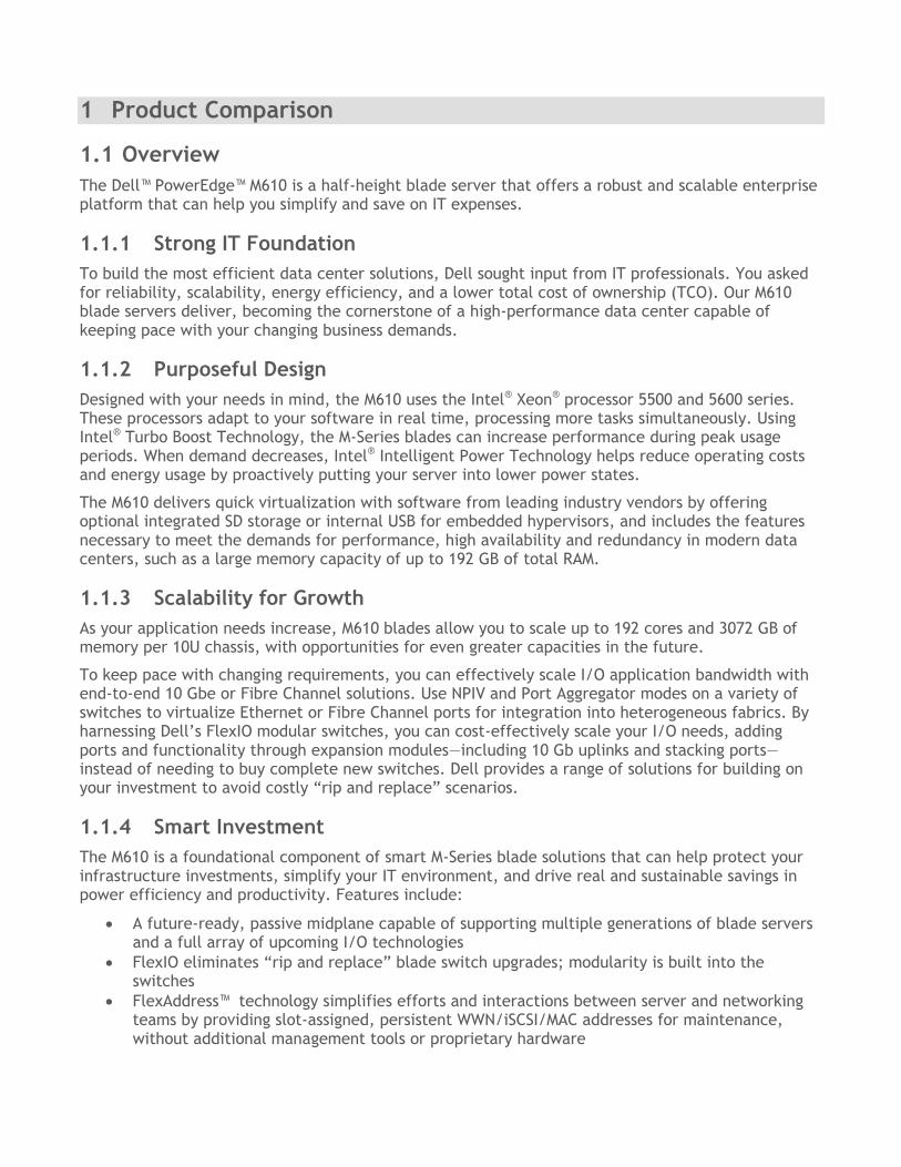
The Dell™ PowerEdge™ M610 is a half-height blade server that offers a robust and scalable enterprise platform that can help you simplify and save on IT expenses.
1.1.1 Strong IT Foundation
To build the most efficient data center solutions, Dell sought input from IT professionals. You asked for reliability, scalability, energy efficiency, and a lower total cost of ownership (TCO). Our M610 blade servers deliver, becoming the cornerstone of a high-performance data center capable of keeping pace with your changing business demands.
1.1.2 Purposeful Design
Designed with your needs in mind, the M610 uses the Intel® Xeon® processor 5500 and 5600 series. These processors adapt to your software in real time, processing more tasks simultaneously. Using Intel® Turbo Boost Technology, the M-Series blades can increase performance during peak usage periods. When demand decreases, Intel® Intelligent Power Technology helps reduce operating costs and energy usage by proactively putting your server into lower power states.
The M610 delivers quick virtualization with software from leading industry vendors by offering optional integrated SD storage or internal USB for embedded hypervisors, and includes the features necessary to meet the demands for performance, high availability and redundancy in modern data centers, such as a large memory capacity of up to 192 GB of total RAM.
1.1.3 Scalability for Growth
As your application needs increase, M610 blades allow you to scale up to 192 cores and 3072 GB of memory per 10U chassis, with opportunities for even greater capacities in the future.
To keep pace with changing requirements, you can effectively scale I/O application bandwidth with end-to-end 10 Gbe or Fibre Channel solutions. Use NPIV and Port Aggregator modes on a variety of switches to virtualize Ethernet or Fibre Channel ports for integration into heterogeneous fabrics. By harnessing Dell’s FlexIO modular switches, you can cost-effectively scale your I/O needs, adding ports and functionality through expansion modules—including 10 Gb uplinks and stacking ports—instead of needing to buy complete new switches. Dell provides a range of solutions for building on your investment to avoid costly ―rip and replace‖ scenarios.
1.1.4 Smart Investment
The M610 is a foundational component of smart M-Series blade solutions that can help protect your infrastructure investments, simplify your IT environment, and drive real and sustainable savings in power efficiency and productivity. Features include:
A future-ready, passive midplane capable of supporting multiple generations of blade servers and a full array of upcoming I/O technologies
FlexIO eliminates ―rip and replace‖ blade switch upgrades; modularity is built into the switches
FlexAddress™ technology simplifies efforts and interactions between server and networking teams by providing slot-assigned, persistent WWN/iSCSI/MAC addresses for maintenance, without additional management tools or proprietary hardware
Dell
Dell PowerEdge M610 Technical Guide 2
Energy Smart Technologies, including ultra-efficient fans and power supplies for outstanding energy efficiency
With savings in time and money previously needed for maintenance, you free up resources that can be used for true innovation.
1.1.5 Simplified Systems Management
The next generation Dell™ OpenManage™ suite offers enhanced operations and standards-based commands designed to integrate with existing systems for effective control.
1.1.6 Lifecycle Controller
Lifecycle Controller is the engine for advanced systems management integrated on the server. Lifecycle Controller simplifies administrator tasks so you can perform a complete set of provisioning functions such as system deployment, system updates, hardware configuration and diagnostics from a single intuitive interface called Unified Server Configurator (USC) in a pre-OS environment. This eliminates the need to use and maintain multiple pieces of disparate CD/DVD media.
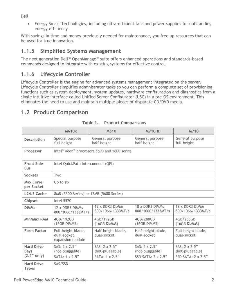
1.2 Product Comparison
Table 1. Product Comparisons
M610x M610 M710HD M710
Description Special purpose full-height
General purpose half-height
General purpose half-height
General purpose full-height
Processor Intel® Xeon® processors 5500 and 5600 series
Front Side Bus
Intel QuickPath Interconnect (QPI)
Sockets Two
Max Cores per Socket
Up to six
L2/L3 Cache 8MB (5500 Series) or 12MB (5600 Series)
Chipset Intel 5520
DIMMs 12 x DDR3 DIMMs 800/1066/1333MT/s
12 x DDR3 DIMMs 800/1066/1333MT/s
18 x DDR3 DIMMs 800/1066/1333MT/s
18 x DDR3 DIMMs 800/1066/1333MT/s
Min/Max RAM 4GB/192GB (16GB DIMMS)
4GB/192GB (16GB DIMMS)
4GB/288GB (16GB DIMMS)
4GB/288GB (16GB DIMMS)
Form Factor Full-height blade, dual-socket, expansion module
Half-height blade, dual-socket
Half-height blade, dual-socket
Full-height blade, dual-socket
Hard Drive Bays (2.5” only)
SAS: 2 x 2.5‖ (hot-pluggable)
SATA: 1 x 2.5‖
SAS: 2 x 2.5‖ (hot-pluggable)
SATA: 1 x 2.5‖
SAS: 2 x 2.5‖ (hot-pluggable)
SSD SATA: 2 x 2.5‖
SAS: 2 x 2.5‖ (hot-pluggable)
SSD SATA: 2 x 2.5‖
Hard Drive Types
SAS/SSD
Dell
Dell PowerEdge M610 Technical Guide 3
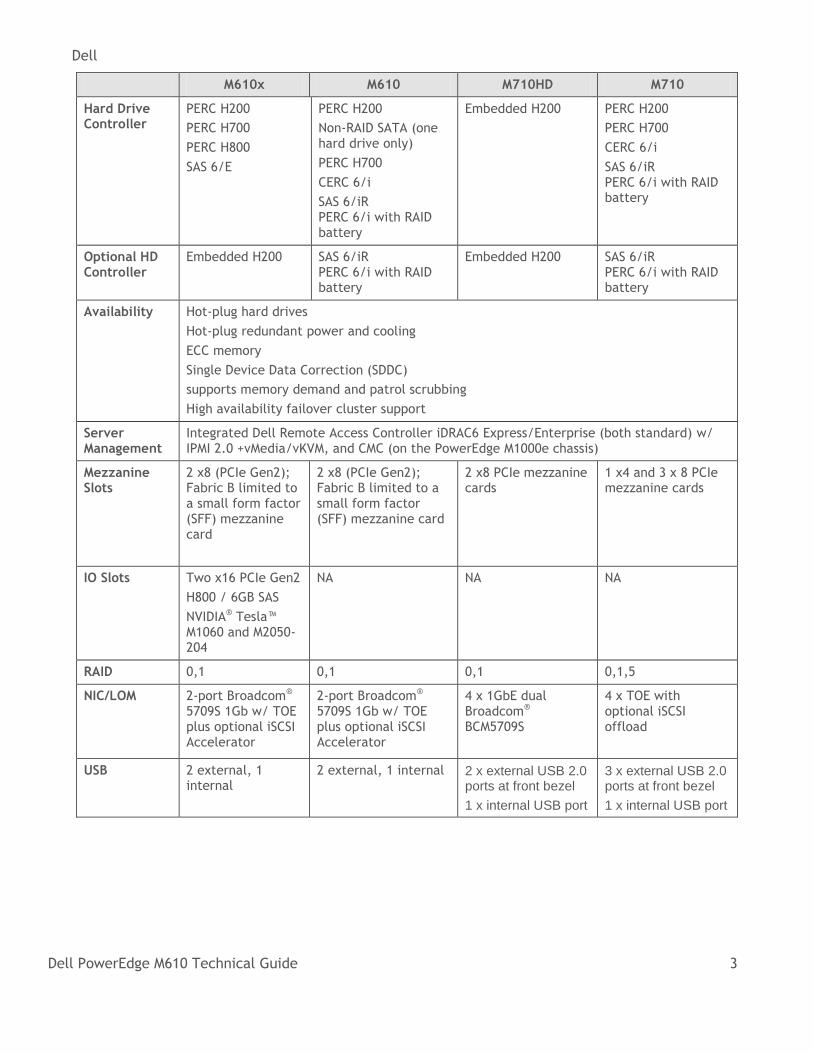
M610x M610 M710HD M710
Hard Drive Controller
PERC Η200
PERC Η700
PERC Η800
SAS 6/E
PERC H200
Non-RAID SATA (one hard drive only)
PERC H700
CERC 6/i
SAS 6/iR PERC 6/i with RAID battery
Embedded H200 PERC H200
PERC H700
CERC 6/i
SAS 6/iR PERC 6/i with RAID battery
Optional HD Controller
Embedded H200 SAS 6/iR PERC 6/i with RAID battery
Embedded H200 SAS 6/iR PERC 6/i with RAID battery
Availability Hot-plug hard drives
Hot-plug redundant power and cooling
ECC memory
Single Device Data Correction (SDDC)
supports memory demand and patrol scrubbing
High availability failover cluster support
Server Management
Integrated Dell Remote Access Controller iDRAC6 Express/Enterprise (both standard) w/ IPMI 2.0 +vMedia/vKVM, and CMC (on the PowerEdge M1000e chassis)
Mezzanine Slots
2 x8 (PCIe Gen2); Fabric B limited to a small form factor (SFF) mezzanine card
2 x8 (PCIe Gen2); Fabric B limited to a small form factor (SFF) mezzanine card
2 x8 PCIe mezzanine cards
1 x4 and 3 x 8 PCIe mezzanine cards
IO Slots Two x16 PCIe Gen2
H800 / 6GB SAS
NVIDIA® Tesla™ M1060 and M2050-204
NA NA NA
RAID 0,1 0,1 0,1 0,1,5
NIC/LOM 2-port Broadcom® 5709S 1Gb w/ TOE plus optional iSCSI Accelerator
2-port Broadcom® 5709S 1Gb w/ TOE plus optional iSCSI Accelerator
4 x 1GbE dual Broadcom® BCM5709S
4 x TOE with optional iSCSI offload
USB 2 external, 1 internal
2 external, 1 internal 2 x external USB 2.0 ports at front bezel
1 x internal USB port
3 x external USB 2.0 ports at front bezel
1 x internal USB port
Dell
Dell PowerEdge M610 Technical Guide 4
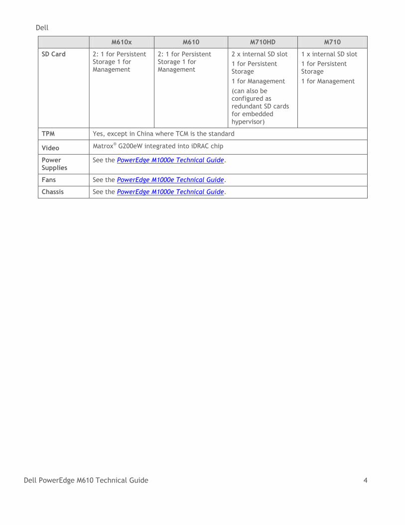
M610x M610 M710HD M710
SD Card 2: 1 for Persistent Storage 1 for Management
2: 1 for Persistent Storage 1 for Management
2 x internal SD slot
1 for Persistent Storage
1 for Management
(can also be configured as redundant SD cards for embedded hypervisor)
1 x internal SD slot
1 for Persistent Storage
1 for Management
TPM Yes, except in China where TCM is the standard
Video Matrox® G200eW integrated into iDRAC chip
Power Supplies
See the PowerEdge M1000e Technical Guide.
Fans See the PowerEdge M1000e Technical Guide.
Chassis See the PowerEdge M1000e Technical Guide.
Dell
Dell PowerEdge M610 Technical Guide 5
2 New Technologies
2.1 Overview
The Dell™ PowerEdge™ M610 is a half-height blade within a PowerEdge M1000e full-height blade enclosure. The PowerEdge M610 features include:
Dual quad- and six-core Intel Xeon processor 5500 and 5600 series
Intel IOH (24D I/O Hub)
Intel QuickPath Architecture
DDR3 memory
DIMM thermal sensors
Internal SD Module
iDRAC6 Express
Dell
Dell PowerEdge M610 Technical Guide 6
3 System Information
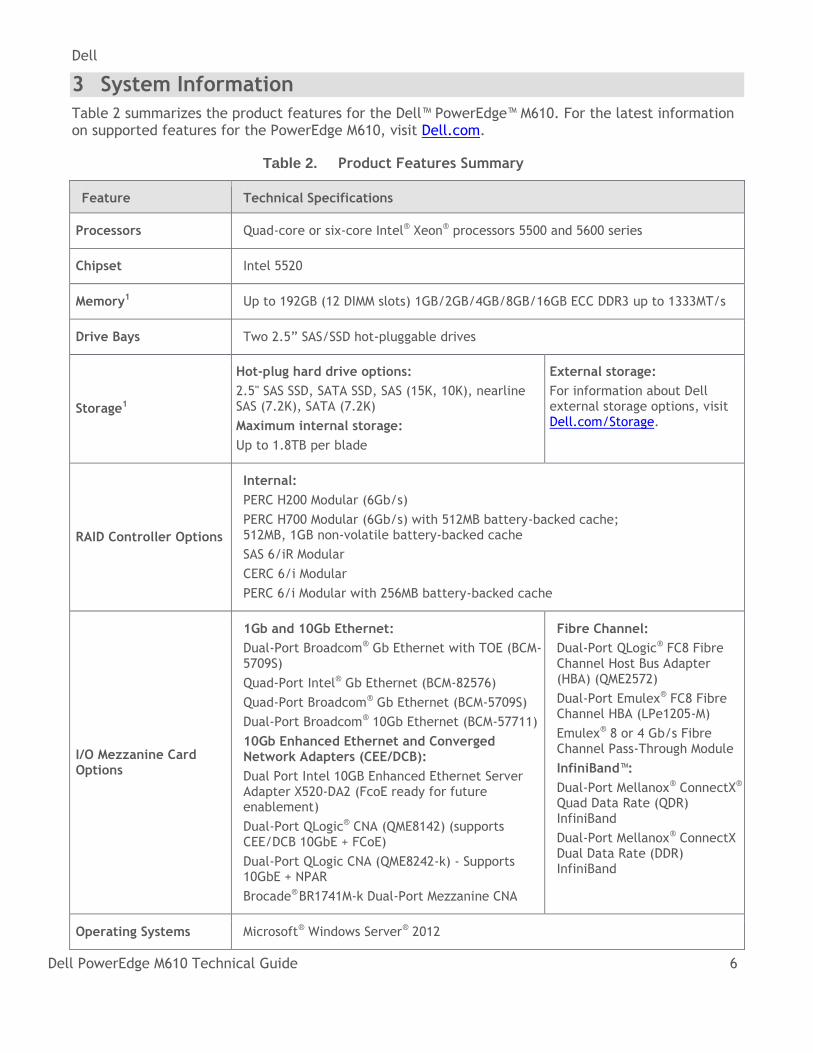
Table 2 summarizes the product features for the Dell™ PowerEdge™ M610. For the latest information on supported features for the PowerEdge M610, visit Dell.com.
Table 2. Product Features Summary
Feature Technical Specifications
Processors Quad-core or six-core Intel® Xeon® processors 5500 and 5600 series
Chipset Intel 5520
Memory1 Up to 192GB (12 DIMM slots) 1GB/2GB/4GB/8GB/16GB ECC DDR3 up to 1333MT/s
Drive Bays Two 2.5‖ SAS/SSD hot-pluggable drives
Storage1
Hot-plug hard drive options:
2.5" SAS SSD, SATA SSD, SAS (15K, 10K), nearline SAS (7.2K), SATA (7.2K)
Maximum internal storage:
Up to 1.8TB per blade
External storage:
For information about Dell external storage options, visit Dell.com/Storage.
RAID Controller Options
Internal:
PERC H200 Modular (6Gb/s)
PERC H700 Modular (6Gb/s) with 512MB battery-backed cache; 512MB, 1GB non-volatile battery-backed cache
SAS 6/iR Modular
CERC 6/i Modular
PERC 6/i Modular with 256MB battery-backed cache
I/O Mezzanine Card Options
1Gb and 10Gb Ethernet:
Dual-Port Broadcom® Gb Ethernet with TOE (BCM-5709S)
Quad-Port Intel® Gb Ethernet (BCM-82576)
Quad-Port Broadcom® Gb Ethernet (BCM-5709S)
Dual-Port Broadcom® 10Gb Ethernet (BCM-57711)
10Gb Enhanced Ethernet and Converged Network Adapters (CEE/DCB):
Dual Port Intel 10GB Enhanced Ethernet Server Adapter X520-DA2 (FcoE ready for future enablement)
Dual-Port QLogic® CNA (QME8142) (supports CEE/DCB 10GbE + FCoE)
Dual-Port QLogic CNA (QME8242-k) - Supports 10GbE + NPAR
Brocade® BR1741M-k Dual-Port Mezzanine CNA
Fibre Channel:
Dual-Port QLogic® FC8 Fibre Channel Host Bus Adapter (HBA) (QME2572)
Dual-Port Emulex® FC8 Fibre Channel HBA (LPe1205-M)
Emulex® 8 or 4 Gb/s Fibre Channel Pass-Through Module
InfiniBand™:
Dual-Port Mellanox® ConnectX® Quad Data Rate (QDR) InfiniBand
Dual-Port Mellanox® ConnectX Dual Data Rate (DDR) InfiniBand
Operating Systems Microsoft® Windows Server® 2012
Dell
Dell PowerEdge M610 Technical Guide 7
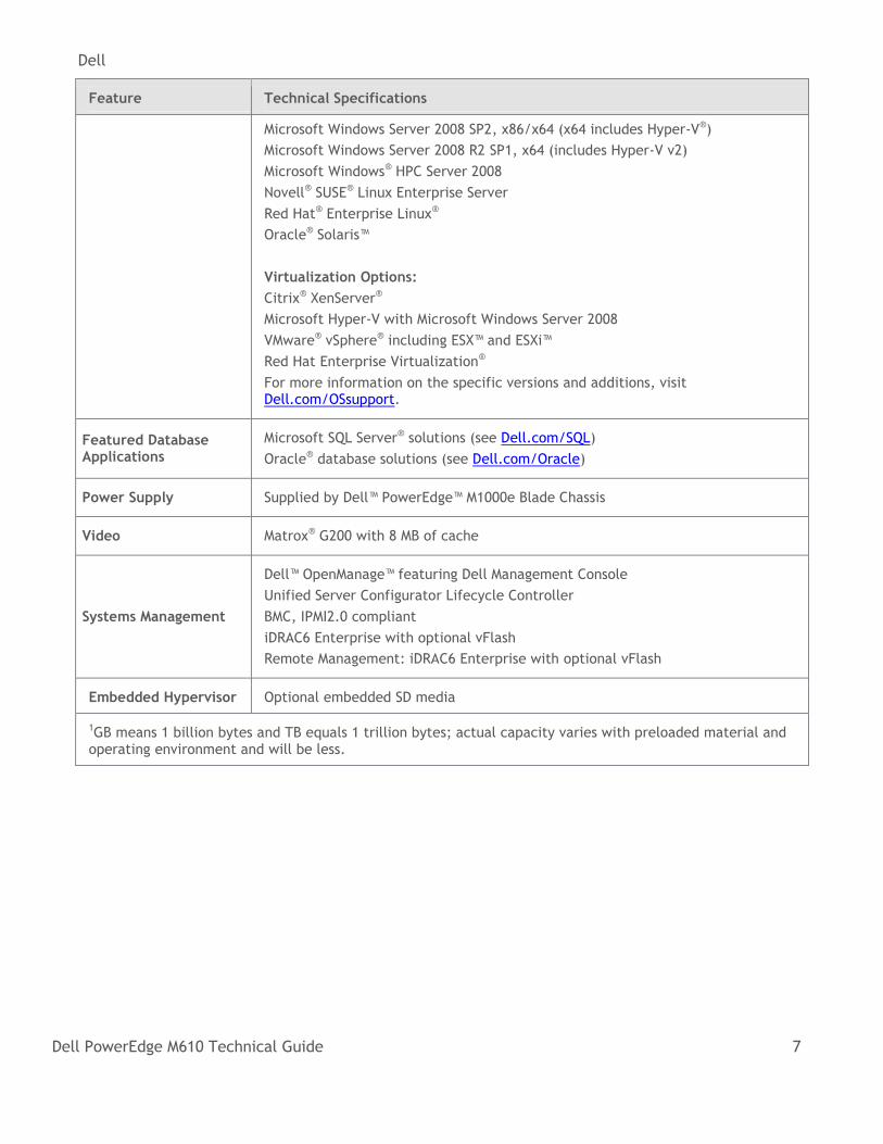
Feature Technical Specifications
Microsoft Windows Server 2008 SP2, x86/x64 (x64 includes Hyper-V®)
Microsoft Windows Server 2008 R2 SP1, x64 (includes Hyper-V v2)
Microsoft Windows® HPC Server 2008
Novell® SUSE® Linux Enterprise Server
Red Hat® Enterprise Linux®
Oracle® Solaris™
Virtualization Options:
Citrix® XenServer®
Microsoft Hyper-V with Microsoft Windows Server 2008
VMware® vSphere® including ESX™ and ESXi™
Red Hat Enterprise Virtualization®
For more information on the specific versions and additions, visit Dell.com/OSsupport.
Featured Database Applications
Microsoft SQL Server® solutions (see Dell.com/SQL)
Oracle® database solutions (see Dell.com/Oracle)
Power Supply Supplied by Dell™ PowerEdge™ M1000e Blade Chassis
Video Matrox® G200 with 8 MB of cache
Systems Management
Dell™ OpenManage™ featuring Dell Management Console
Unified Server Configurator Lifecycle Controller
BMC, IPMI2.0 compliant
iDRAC6 Enterprise with optional vFlash
Remote Management: iDRAC6 Enterprise with optional vFlash
Embedded Hypervisor Optional embedded SD media
1GB means 1 billion bytes and TB equals 1 trillion bytes; actual capacity varies with preloaded material and operating environment and will be less.
Dell
Dell PowerEdge M610 Technical Guide 8
4 Mechanical
4.1 Chassis Description
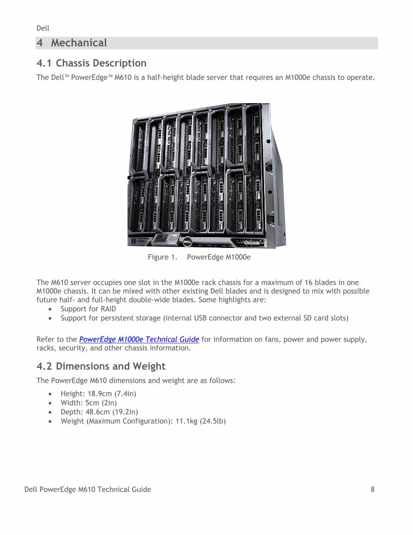
The Dell™ PowerEdge™ M610 is a half-height blade server that requires an M1000e chassis to operate.
Figure 1. PowerEdge M1000e
The M610 server occupies one slot in the M1000e rack chassis for a maximum of 16 blades in one M1000e chassis. It can be mixed with other existing Dell blades and is designed to mix with possible future half- and full-height double-wide blades. Some highlights are:
Support for RAID
Support for persistent storage (internal USB connector and two external SD card slots)
Refer to the PowerEdge M1000e Technical Guide for information on fans, power and power supply, racks, security, and other chassis information.
4.2 Dimensions and Weight
The PowerEdge M610 dimensions and weight are as follows:
Height: 18.9cm (7.4in)
Width: 5cm (2in)
Depth: 48.6cm (19.2in)
Weight (Maximum Configuration): 11.1kg (24.5lb)
Dell
Dell PowerEdge M610 Technical Guide 9
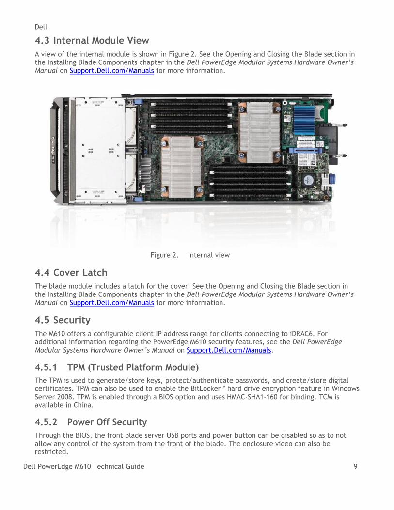
4.3 Internal Module View
A view of the internal module is shown in Figure 2. See the Opening and Closing the Blade section in the Installing Blade Components chapter in the Dell PowerEdge Modular Systems Hardware Owner’s Manual on Support.Dell.com/Manuals for more information.
Figure 2. Internal view
4.4 Cover Latch
The blade module includes a latch for the cover. See the Opening and Closing the Blade section in the Installing Blade Components chapter in the Dell PowerEdge Modular Systems Hardware Owner’s Manual on Support.Dell.com/Manuals for more information.
4.5 Security
The M610 offers a configurable client IP address range for clients connecting to iDRAC6. For additional information regarding the PowerEdge M610 security features, see the Dell PowerEdge Modular Systems Hardware Owner’s Manual on Support.Dell.com/Manuals.
4.5.1 TPM (Trusted Platform Module)
The TPM is used to generate/store keys, protect/authenticate passwords, and create/store digital certificates. TPM can also be used to enable the BitLocker™ hard drive encryption feature in Windows Server 2008. TPM is enabled through a BIOS option and uses HMAC-SHA1-160 for binding. TCM is available in China.
4.5.2 Power Off Security
Through the BIOS, the front blade server USB ports and power button can be disabled so as to not allow any control of the system from the front of the blade. The enclosure video can also be restricted.
Dell
Dell PowerEdge M610 Technical Guide 10
The BIOS System Setup program’s system security screen allows administrators to set the system password, control TPM activation and reporting, clear the TPM’s memory, and disable the power button and USB ports.
4.6 USB Key
The M610 supports the following USB devices:
• DVD (bootable; requires two USB ports)
• USB Key (bootable)
• Keyboard (only one USB keyboard is supported)
• Mouse (only one USB mouse is supported)
4.7 Battery
A replaceable coin cell CR2032 3V battery is mounted on the planar to provide backup power for the Real-Time Clock and CMOS RAM on the ICH9 chip.
4.8 Field Replaceable Units (FRU)
The planar contains a serial EEPROM to contain FRU information including Dell part number, part revision level, and serial number.
4.9 User Accessible Jumpers, Sockets, and Connectors
For information, see the System Board Information chapter in the Dell PowerEdge Modular Systems Hardware Owner’s Manual on Support.Dell.com/Manuals.
Dell
Dell PowerEdge M610 Technical Guide 11
5 Power, Thermal, Acoustic
5.1 Power Supplies
See the PowerEdge M1000e Technical Guide for information on power supplies and power supply specifications.
5.2 Power Efficiency
One of the main features of blade servers is enhanced power efficiency. The Dell™ PowerEdge™ M610 achieves higher power efficiency by implementing the following features:
• User-configurable power options through the M1000e Chassis Management Controller (CMC) (see the M1000e documentation online at Dell.com/Support for further details)
• Improved power budgeting
• Voltage Regulator (VR) efficiency improvements
• Processor VR dynamic phase shedding
• Switching regulators instead of linear regulators
• Closed loop thermal throttling
• Use of DDR3 memory (lower voltage compared to DDR2)
• Memory VR static phase shedding
• BIOS Power/Performance options page
• Active Power Controller (BIOS-based processor P-state manager)
• Ability to throttle memory
• Ability to disable a processor core
• Ability to turn off embedded NICs when not being used
• Energy Smart components at the M1000e chassis level to selectively enable more computing performance with less power consumption.
5.3 Thermal Operating and Storage Specifications
The M610 thermal solution includes:
Optimized airflow impedance for individual blade and chassis level airflow balancing
Custom air baffling directs airflow through the components to maintain proper cooling
Custom designed heat sinks maintain processor, DIMM, and board-level chip temperatures within thermal design targets
Highly Optimized Fan Control Algorithm o Base fan speeds are a function of hardware configuration and ambient temperature to
minimize airflow for a given environment. o Component algorithms: CPU PID, DIMMs, HW Configuration, IOH, GPU, and External
Ambient. o The highest fan speed request from the above algorithms is used to set the
appropriate fan speed for the blade. o Ambient and HW Configuration sets the minimum – other algorithms increase fan speed
to maintain proper cooling.
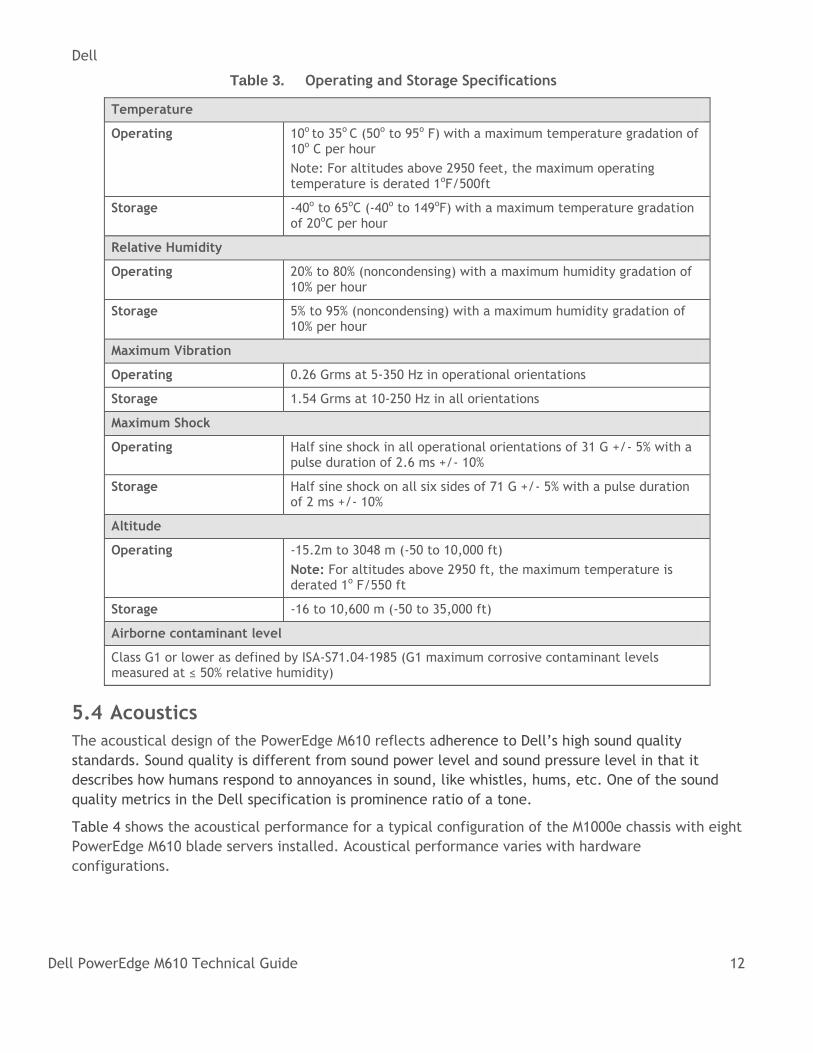
Thermal specifications for the PowerEdge M610 are detailed in Table 3 along with other important operating and storage information.
Dell
Dell PowerEdge M610 Technical Guide 12
Table 3. Operating and Storage Specifications
Temperature
Operating 10o to 35o C (50o to 95o F) with a maximum temperature gradation of 10o C per hour
Note: For altitudes above 2950 feet, the maximum operating temperature is derated 1oF/500ft
Storage -40o to 65oC (-40o to 149oF) with a maximum temperature gradation of 20oC per hour
Relative Humidity
Operating 20% to 80% (noncondensing) with a maximum humidity gradation of 10% per hour
Storage 5% to 95% (noncondensing) with a maximum humidity gradation of 10% per hour
Maximum Vibration
Operating 0.26 Grms at 5-350 Hz in operational orientations
Storage 1.54 Grms at 10-250 Hz in all orientations
Maximum Shock
Operating Half sine shock in all operational orientations of 31 G +/- 5% with a pulse duration of 2.6 ms +/- 10%
Storage Half sine shock on all six sides of 71 G +/- 5% with a pulse duration of 2 ms +/- 10%
Altitude
Operating -15.2m to 3048 m (-50 to 10,000 ft)
Note: For altitudes above 2950 ft, the maximum temperature is derated 1o F/550 ft
Storage -16 to 10,600 m (-50 to 35,000 ft)
Airborne contaminant level
Class G1 or lower as defined by ISA-S71.04-1985 (G1 maximum corrosive contaminant levels measured at ≤ 50% relative humidity)
5.4 Acoustics
The acoustical design of the PowerEdge M610 reflects adherence to Dell’s high sound quality
standards. Sound quality is different from sound power level and sound pressure level in that it
describes how humans respond to annoyances in sound, like whistles, hums, etc. One of the sound
quality metrics in the Dell specification is prominence ratio of a tone.
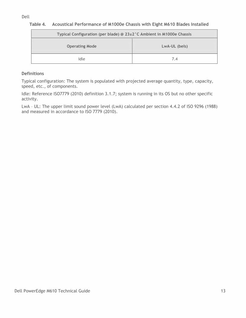
Table 4 shows the acoustical performance for a typical configuration of the M1000e chassis with eight
PowerEdge M610 blade servers installed. Acoustical performance varies with hardware
configurations.
Dell
Dell PowerEdge M610 Technical Guide 13
Table 4. Acoustical Performance of M1000e Chassis with Eight M610 Blades Installed
Typical Configuration (per blade) @ 23±2°C Ambient in M1000e Chassis
Operating Mode LwA-UL (bels)
Idle 7.4
Definitions
Typical configuration: The system is populated with projected average quantity, type, capacity, speed, etc., of components.
Idle: Reference ISO7779 (2010) definition 3.1.7; system is running in its OS but no other specific activity.
LwA – UL: The upper limit sound power level (LwA) calculated per section 4.4.2 of ISO 9296 (1988) and measured in accordance to ISO 7779 (2010).
Dell
Dell PowerEdge M610 Technical Guide 14
6 Processors
6.1 Overview
The Intel® Xeon® processor 5500 and 5600 series are designed specifically for servers and workstation applications. These processors feature quad-core processing to maximize performance and performance-per-watt for data center infrastructures and highly-dense deployments. They feature Intel Core™ micro-architecture and Intel 64 architecture for flexibility in 64-bit and 32-bit applications and operating systems, and they use a 1366-contact Flip-Chip Land Grid Array (FC-LGA) package that plugs into a surface-mount socket. The M610 provides support for up to two processors.
6.2 Features
Key features of the Intel Xeon processor 5500 series include:
Up to four cores per processor
Two point-to-point QuickPath Interconnect links at 6.4 GT/s
45 nm process technology
No termination requirement for non-populated processors (must populate CPU socket 1 first)
Integrated QuickPath DDR3 memory controller
64-byte cache line size
RISC/CISC hybrid architecture
Compatibility with existing x86 code base
MMX™ support
Execute Disable Bit
Intel Wide Dynamic Execution
Ability to execute up to four instructions per clock cycle
Simultaneous Multi-Threading (SMT) capability
Support for processor Turbo Mode (on certain SKUs)
Processor frequency increases if operating below thermal, power, and current limits
Streaming SIMD (Single Instruction, Multiple Data) Extensions 2, 3, and 4
Intel® 64 Technology
Intel® VT-x and VT-d technology for virtualization support
Enhanced Intel® SpeedStep® technology
Demand-based switching for active processor power management as well as support for ACPI P-States, C-States and T-States
The Intel Xeon processor 5600 series encompasses all the features of the 5500 series, and also includes the following:
• New top BIN processors at 130W TDP
• Support for DDR3L, 1.35v DIMMs for even lower system power
• Support for memory sparing
• AES-NI (hardware encryption assist) for more efficient encryption for uses such as online transactions SSL.
• Intel TXT (Trusted Execution Technology) provides hardware assisted protection against emerging software attacks
Dell
Dell PowerEdge M610 Technical Guide 15
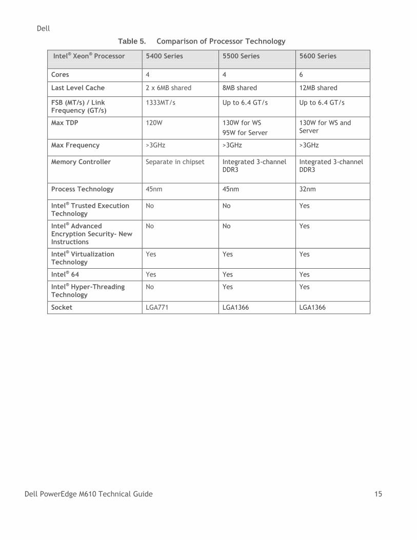
Table 5. Comparison of Processor Technology
Intel® Xeon® Processor 5400 Series 5500 Series 5600 Series
Cores 4 4 6
Last Level Cache 2 x 6MB shared 8MB shared 12MB shared
FSB (MT/s) / Link Frequency (GT/s)
1333MT/s Up to 6.4 GT/s Up to 6.4 GT/s
Max TDP 120W 130W for WS
95W for Server
130W for WS and Server
Max Frequency >3GHz >3GHz >3GHz
Memory Controller Separate in chipset Integrated 3-channel DDR3
Integrated 3-channel DDR3
Process Technology 45nm 45nm 32nm
Intel® Trusted Execution Technology
No No Yes
Intel® Advanced Encryption Security- New Instructions
No No Yes
Intel® Virtualization Technology
Yes Yes Yes
Intel® 64 Yes Yes Yes
Intel® Hyper-Threading Technology
No Yes Yes
Socket LGA771 LGA1366 LGA1366
Dell
Dell PowerEdge M610 Technical Guide 16
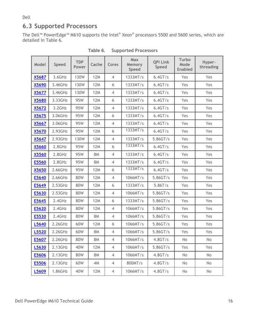
6.3 Supported Processors
The Dell™ PowerEdge™ M610 supports the Intel® Xeon® processors 5500 and 5600 series, which are detailed in Table 6.
Table 6. Supported Processors
Model Speed TDP
Power Cache Cores
Max Memory Speed
QPI Link Speed
Turbo Mode
Enabled
Hyper-threading
X5687 3.6GHz 130W 12M 4 1333MT/s 6.4GT/s Yes Yes
X5690 3.46GHz 130W 12M 6 1333MT/s 6.4GT/s Yes Yes
X5677 3.46GHz 130W 12M 4 1333MT/s 6.4GT/s Yes Yes
X5680 3.33GHz 95W 12M 6 1333MT/s 6.4GT/s Yes Yes
X5672 3.2GHz 95W 12M 4 1333MT/s 6.4GT/s Yes Yes
X5675 3.06GHz 95W 12M 6 1333MT/s 6.4GT/s Yes Yes
X5667 3.06GHz 95W 12M 4 1333MT/s 6.4GT/s Yes Yes
X5670 2.93GHz 95W 12M 6 1333MT/s 6.4GT/s Yes Yes
X5647 2.93GHz 130W 12M 4 1333MT/s 5.86GT/s Yes Yes
X5660 2.8GHz 95W 12M 6 1333MT/s 6.4GT/s Yes Yes
X5560 2.8GHz 95W 8M 4 1333MT/s 6.4GT/s Yes Yes
E5560 2.8GHz 95W 8M 4 1333MT/s 6.4GT/s Yes Yes
X5650 2.66GHz 95W 12M 6 1333MT/s 6.4GT/s Yes Yes
E5640 2.66GHz 80W 12M 4 1066MT/s 5.86GT/s Yes Yes
E5649 2.53GHz 80W 12M 6 1333MT/s 5.86T/s Yes Yes
E5630 2.53GHz 80W 12M 4 1066MT/s 5.86GT/s Yes Yes
E5645 2.4GHz 80W 12M 6 1333MT/s 5.86GT/s Yes Yes
E5620 2.4GHz 80W 12M 4 1066MT/s 5.86GT/s Yes Yes
E5530 2.4GHz 80W 8M 4 1066MT/s 5.86GT/s Yes Yes
L5640 2.26GHz 60W 12M 6 1066MT/s 5.86GT/s Yes Yes
L5520 2.26GHz 60W 8M 4 1066MT/s 5.86GT/s Yes Yes
E5607 2.26GHz 80W 8M 4 1066MT/s 4.8GT/s No No
L5630 2.13GHz 40W 12M 4 1066MT/s 5.86GT/s Yes Yes
E5606 2.13GHz 80W 8M 4 1066MT/s 4.8GT/s No No
E5506 2.13GHz 60W 4M 4 800MT/s 4.8GT/s No No
L5609 1.86GHz 40W 12M 4 1066MT/s 4.8GT/s No No
Dell
Dell PowerEdge M610 Technical Guide 17
6.4 Processor Installation
See the Processors section in the Installing Blade Components chapter in the Dell PowerEdge Modular Systems Hardware Owner’s Manual on Support.Dell.com/Manuals.
Dell
Dell PowerEdge M610 Technical Guide 18
7 Memory
7.1 Overview
The Dell™ PowerEdge™ M610 uses DDR3 memory providing a high-performance, high-speed memory interface capable of low latency response and high throughput. The M610 supports Registered ECC DDR3 DIMMs (RDIMM) as well as the low-voltage RDIMMs and Unbuffered ECC DDR3 DIMMs (UDIMM).
The DDR3 memory interface consists of three channels with up to two RDIMMs or UDIMMs per channel for single/dual rank and up to two RDIMMs per channel for quad rank. The interface uses 2 GB, 4 GB, or 8 GB RDIMMs. 1 GB or 2 GB UDIMMs are also supported. The memory mode is dependent on how the memory is populated in the system, according to the following guidelines:
Three channels per processor populated identically o The system is typically set to run in Memory Optimized (Independent Channel) mode in this
configuration. This mode offers the most DIMM population flexibility and system memory capacity, but offers the least number of RAS (reliability, availability, and serviceability) features.
o All three channels must be populated identically o Memory sparing is not supported on the M610 with 5500 series processors.
The first two channels per processor populated identically with the third channel unused o Two channels typically operate in Advanced ECC (Lockstep) mode with each other by having
the cache line split across both channels. This mode provides improved RAS features (SDDC support for x8-based memory).
o For Memory Mirroring, two channels operate as mirrors of each other (write functions go to both channels and read functions alternate between the two channels).
One channel per processor populated (This is a simple Memory Optimized mode. No mirroring or sparing is supported.)
The M610 memory interface supports memory demand and patrol scrubbing, single-bit correction, and multi-bit error detection. Correction of an x4 or x8 device failure is also possible with SDDC in the Advanced ECC mode. Additionally, correction of an x4 device failure is possible in the Memory Optimized mode.
7.2 DIMMs Supported
The following memory requirements apply to the M610:
If DIMMs of different speeds are mixed, all channels operate at the fastest common frequency.
RDIMMs and UDIMMs cannot be mixed.
If memory mirroring is enabled, identical DIMMs must be installed in the same slots across both channels. The third channel of each processor is unavailable for memory mirroring.
The first DIMM slot in each channel is color-coded with white ejection tabs for ease of installation.
The M610 memory system supports up to 12 DIMMs.
DIMMs must be installed in each channel starting with the DIMM farthest from the processor.
Population order is identified by the silkscreen designator and the System Information Label (SIL) located on the chassis cover.
Dell
Dell PowerEdge M610 Technical Guide 19
7.3 Memory Features
Key features of the M610 memory system include:
Registered (RDIMM) and Unbuffered (UDIMM) ECC DDR3 technology
Each channel carries 64 data and eight ECC bits
Support for up to 192 GB of RDIMM memory (with twelve 16 GB RDIMMs)
Support for up to 24 GB of UDIMM memory (with twelve 2 GB UDIMMs)
Support for 1066/1333 MT/s single and dual rank DIMMs
Support for 1066 MT/s quad rank DIMMs
Single DIMM configuration only with DIMM in socket A1
ODT support (On Die Termination)
Clock gating (CKE) to conserve power when DIMMs are not accessed (DIMMs enter a low-power self-refresh mode)
I2C access to SPD EEPROM for access to RDIMM thermal sensors
Single Bit Error Correction
SDDC (Single Device Data Correction – x4 or x8 devices)
Support for Closed Loop Thermal Management on RDIMMs and UDIMMs
Multi Bit Error Detection
Support for Memory Optimized Mode
Support for Advanced ECC mode
Support for Memory Mirroring
Memory sparing is not supported on 5500 series processors but it is supported on systems using 5600 series processors. While 800 MT/s DIMMs are not supported, the installation of two quad-rank 1066 MT/s DIMMs will operate at 800 MT/s.
7.4 Memory Speed Limitations
The memory frequency is determined by a variety of inputs:
Speed of the DIMMs
Speed supported by the processor
Configuration of the DIMMs
The M610 supports two DIMMs per channel at 1333 MT/s. To run the maximum memory configuration (12 x 16 GB DIMMS = 192 GB) at 1333 MT/s, use dual-rank 16 GB DIMMs.
If you want to run at 1066MT/s, the maximum amount of quad-rank DIMMs allowed is 1DPC (DIMM per channel), which equals three DIMMs per CPU or six DIMMs total.
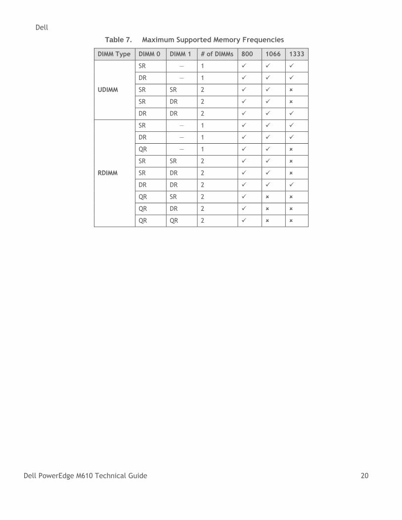
For quad-rank DIMMs mixed with single- or dual-rank DIMMs, the quad-rank DIMM needs to be in the slot with the white ejection tabs (the first DIMM slot in each channel). There is no requirement for the order of single-rank and dual-rank DIMMs. Table 7 shows the memory populations and the maximum frequency achievable for that configuration.
Dell
Dell PowerEdge M610 Technical Guide 20
Table 7. Maximum Supported Memory Frequencies
DIMM Type DIMM 0 DIMM 1 # of DIMMs 800 1066 1333
UDIMM
SR — 1
DR — 1
SR SR 2
SR DR 2
DR DR 2
RDIMM
SR — 1
DR — 1
QR — 1
SR SR 2
SR DR 2
DR DR 2
QR SR 2
QR DR 2
QR QR 2
Dell
Dell PowerEdge M610 Technical Guide 21
8 Chipset
8.1 Overview
The Dell™ PowerEdge™ M610 system board incorporates the Intel 5520 chipset for I/O and processor interfacing. The chipset was designed to support the Intel® Xeon® Processor 5500 and 5600 series, QuickPath Interconnect, and DDR3 memory technology. The chipset consists of the I/O Hub (IOH) and Intel I/O Controller Hub 9 (ICH9).
8.2 I/O Hub (IOH)
The M610 system board uses the Intel 5520 chipset 24D IOH to provide a link between the processor(s) and I/O components. The main components of the IOH consist of two full-width QuickPath Interconnect links (one to each processor), 36 lanes of PCI Express Gen2, a x4 Direct Media Interface (DMI), and an integrated IOxAPIC.
8.2.1 QuickPath Interconnect (QPI)
The QuickPath Interconnect architecture consists of serial point-to-point interconnects for the processors and the IOH. The M610 has a total of three QuickPath Interconnect (QPI) links: one link connecting the processors and links connecting both processors with the IOH. Each link consists of 20 lanes (full-width) in each direction with a link speed of 6.4 GT/s. An additional lane is reserved for a forwarded clock. Data is sent over the QPI links as packets.
The QuickPath architecture implemented in the IOH and processors features four layers. The Physical layer consists of the actual connection between components. It supports Polarity Inversion and Lane Reversal for optimizing component placement and routing. The Link layer is responsible for flow control and the reliable transmission of data. The Routing layer is responsible for the routing of QPI data packets. Finally, the Protocol layer is responsible for high-level protocol communications, including the implementation of a MESIF (Modify, Exclusive, Shared, Invalid, Forward) cache coherence protocol.
8.2.2 IOH PCI Express
PCI Express is a serial point-to-point interconnect for I/O devices. PCIe Gen2 doubles the signaling bit rate of Gen1 from 2.5 Gb/s to 5 Gb/s. Each of the PCIe Gen2 ports are backwards-compatible with Gen1 transfer rates.
8.2.3 Direct Media Interface (DMI)
The DMI connects the IOH with the Intel I/O Controller Hub 9 (ICH9). The DMI is equivalent to a x4 PCIe Gen1 link with a transfer rate of 1 GB/s in each direction.
8.3 I/O Controller Hub 9 (ICH9)
ICH9 is a highly-integrated I/O controller, supporting the following functions:
Serial ATA (SATA) ports with transfer rates up to 300 MB/s
Six UHCI and two EHCI (high-speed 2.0) USB host controllers, with up to 12 USB ports ( M610 provides four of these ports for internal and external use)
Power management interface (ACPI 3.0b compliant)
Platform Environmental Control Interface (PECI)
I/O interrupt controller
Dell
Dell PowerEdge M610 Technical Guide 22
SMBus 2.0 controller
Low Pin Count (LPC) interface to Trusted Platform Module (TPM), and SPI-VU
Serial Peripheral Interface (SPI) support for up to two devices (M610 BIOS is connected to the ICH9 using SPI)
Dell
Dell PowerEdge M610 Technical Guide 23
9 BIOS
9.1 Overview
The Dell™ PowerEdge™ M610 BIOS is based on the Dell BIOS core, and supports the following features:
Intel® Xeon® processor 5500 and 5600 series 2S support
Simultaneous Multi-Threading (SMT) support
CPU Turbo Mode support
PCI 2.3 compliant
Plug and play 1.0a compliant
MP (Multiprocessor) 1.4 compliant
Ability to boot from hard drive, optical drive, iSCSI drive, USB key, and SD card
ACPI support
Direct Media Interface (DMI) support
PXE, ISCSI, and WOL support for on-board NIC
Memory mirroring
SETUP access through F2 key at end of POST
USB 2.0 (USB boot code is 1.1 compliant)
F1/F2 error logging in CMOS
Virtual KVM, CD, and floppy support
Unified Server Configurator (UEFI 2.1) support
Power management support including DBS, Power Inventory, and multiple power profiles
9.2 Supported ACPI States
The M610 supports the standard Advanced Configuration and Power Interface (ACPI) states.
To learn more, see http://www.acpi.info/.
Dell
Dell PowerEdge M610 Technical Guide 24
10 Embedded NICs/LAN on Motherboard (LOM)
10.1 Overview
The Dell™ PowerEdge™ M610 planar has two embedded Broadcom® 5709S dual-port LAN controllers as independent Gigabit Ethernet interface devices. The following information details the features of the LAN devices:
• x4 PCI Express Gen2 capable interface (M610 operates this controller at Gen1 speed )
• Integrated MAC and PHY
• 3072x18 Byte context memory
• 64 KB receive buffer
• TOE (TCP Offload Engine)
• RDMA controller (RNIC)
• NC-SI (Network Controller-Sideband Interface) connection for manageability
• Wake-On-LAN (WOL)
• PXE 2.0 remote boot
• iSCSI boot
• IPv4 and IPv6 support
• Bare metal deployment support
• ISCSI offload accelerator used for offloading ISCSI traffic as an ISCSI accelerator/HBA (optionally enabled through a hardware key)
The embedded NICs are not sharable with iDRAC since the blade iDRAC has a dedicated 100 Mbps link (Fabric D).
10.2 Platform Networking LAN on Motherboard (LOM) Technology Overview
The PowerEdge M610 has two Ethernet ports because it includes two built-in dual-port 1GbE converged networking (CNIC) LOMs based on Broadcom 5709 controllers. The M610 supports multiple functions over a unified fabric to help manage Ethernet, iSCSI, and remote management traffic on each port simultaneously.
Enterprise networks that use multiple protocols and multiple network fabrics benefit from the Broadcom C-NICs LOMs’ ability to combine network traffic, storage, and clustering over a single Ethernet fabric by boosting server processor performance and memory utilization while alleviating I/O bottlenecks.
Each BCM5709S LOM provides dual 10/100/1000BASE-T Gigabit Ethernet functions, an IEEE802.3-compliant media access controller (MAC), and a UTP copper physical layer transceiver solution for high-performance network applications. It enables simultaneous convergence of all networked communications possible in a server, such as data network (LAN), storage network (such as block, iSCSI, or file [for example, CIFS/NFS]), and clustering (such as High-Performance Computing [HPC]).
Dell
Dell PowerEdge M610 Technical Guide 25
11 I/O Slots (I/O Mezzanine Card Options for M1000e)
11.1 Overview
The Dell™ PowerEdge™ M610 has two PCIe x8 Gen2 mezzanine card slots. Installation of mezzanine cards requires an M1000e I/O Module (IOM) of the same fabric technology to be installed in the corresponding fabric slot of the mezzanine to support data flow through that fabric/slot.
11.2 Options
Available options for mezzanine card slots include the following:
Broadcom® Dual-Port 5709
Broadcom Quad-Port 5709
Intel® ET Quad-Port 82576
Broadcom Dual-Port 57711
Brocade® CNA Dual-Port BR1741M-k
Intel Ethernet X520 10GbE x/k
QLogic® CNA QME8142
QLogic CNA QME8242-k
Emulex® CNA OCM10102FM
QLogic QME2572 (FC8)
Emulex LPe1205 (FC8)
Mellanox® ConnectX®-2 DDR IB (SFF)
Mellanox ConnectX-2 QDR IB (SFF)
Dell
Dell PowerEdge M610 Technical Guide 26
12 Storage
12.1 Overview
The Dell™ PowerEdge™ M610 supports two 2.5‖ storage drives that connect to its hot-plug backplane. These drives can be either SATA or SAS, and either HDD or SSD, though if two are installed, they both must be of the same technology type.
All enterprise-class 2.5‖ storage drives sold by Dell are qualified, including those that offer Self Encrypting Drive functionality as well as the 6Gb SAS drives. All storage drives used with the PERC H700 must be purchased from Dell.
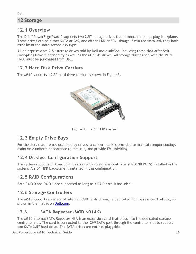
12.2 Hard Disk Drive Carriers
The M610 supports a 2.5‖ hard drive carrier as shown in Figure 3.
Figure 3. 2.5‖ HDD Carrier
12.3 Empty Drive Bays
For the slots that are not occupied by drives, a carrier blank is provided to maintain proper cooling, maintain a uniform appearance to the unit, and provide EMI shielding.
12.4 Diskless Configuration Support
The system supports diskless configuration with no storage controller (H200/PERC 7i) installed in the system. A 2.5‖ HDD backplane is installed in this configuration.
12.5 RAID Configurations
Both RAID 0 and RAID 1 are supported as long as a RAID card is included.
12.6 Storage Controllers
The M610 supports a variety of internal RAID cards through a dedicated PCI Express Gen1 x4 slot, as shown in the matrix on Dell.com.
12.6.1 SATA Repeater (MOD N014K)
The M610 internal SATA Repeater HBA is an expansion card that plugs into the dedicated storage controller slot. The card is connected to the ICH9 SATA port through the controller slot to support one SATA 2.5‖ hard drive. The SATA drives are not hot-pluggable.
Dell
Dell PowerEdge M610 Technical Guide 27
12.6.2 SAS 6/iR
The M610 internal SAS 6/iR HBA is an expansion card that plugs into the dedicated storage controller slot. This card incorporates two four-channel SAS IOCs for connection to SAS hard disk drives (SATA not supported). This card is designed in a form factor that allows the same card to be used in any blade server with a storage card connector. RAID 0 and 1 are supported.
12.6.3 CERC 6/iR
For a hardware RAID solution, the CERC 6/iR is an option. The CERC 6/iR uses the LSI 1078 ROC (RAID on Chip) processor with a PCI Express host interface and DDR2 memory. A battery is not available with this card. For details of this card, see the PERC6 Hardware Product Specification.
12.6.4 PERC 6/i
For another hardware RAID solution, the PERC 6/i is also an option. The PERC 6/i uses the LSI 1078 ROC (RAID on Chip) processor with a PCI Express host interface and DDR2 memory. A battery is available with this card. For details of this card, see the PERC6 Hardware Product Specification.
12.6.5 PERC H200 (Modular version)
The PERC H200M is an entry RAID solution with no cache.
12.6.6 PERC H700 (Modular version)
See the PERC H700 Technical Guidebook for more information on PERC H700M.
12.7 Hard Drive LED Indicators
Each disk drive carrier has two LED indicators visible from the front of the system. One is a green LED for disk activity and the other is a bicolor (Green/Amber) LED for status information. The activity LED is driven by the disk drive during normal operation. The bicolor LED is controlled by the SEP device on the backplane. Both LEDs are used to indicate certain conditions under direction of a storage controller.
12.8 Optical Drives
Optical drives are optional in all M610 systems and connect to the blade through the front USB interface. The following internal slim-line drives are available on M610: DVD-ROM and DVD+RW. PATA (IDE) optical drives are not supported.
Dell
Dell PowerEdge M610 Technical Guide 28
13 Video (PCI Video)
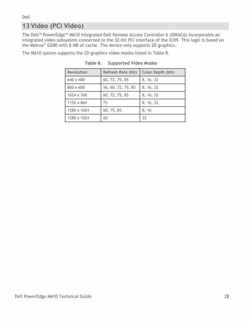
The Dell™ PowerEdge™ M610 Integrated Dell Remote Access Controller 6 (iDRAC6) incorporates an integrated video subsystem connected to the 32-bit PCI interface of the ICH9. This logic is based on the Matrox® G200 with 8 MB of cache. The device only supports 2D graphics.
The M610 system supports the 2D graphics video modes listed in Table 8.
Table 8. Supported Video Modes
Resolution Refresh Rate (Hz) Color Depth (bit)
640 x 480 60, 72, 75, 85 8, 16, 32
800 x 600 56, 60, 72, 75, 85 8, 16, 32
1024 x 768 60, 72, 75, 85 8, 16, 32
1152 x 864 75 8, 16, 32
1280 x 1024 60, 75, 85 8, 16
1280 x 1024 60 32
Dell
Dell PowerEdge M610 Technical Guide 29
14 Rack Information
For information on rack and cable accessories for the Dell™ PowerEdge™ M610, see the PowerEdge M1000e Technical Guide and the M1000e Rack and Cable Advisor Tool.
Dell
Dell PowerEdge M610 Technical Guide 30
15 Operating Systems
The Dell™ PowerEdge™ M610 is designed to meet the Microsoft® WinLogo 3.0 design specifications. For the most up-to-date information, see the Operating System Support Matrix for Dell PowerEdge Systems on Dell.com.
Dell
Dell PowerEdge M610 Technical Guide 31
16 Virtualization
16.1 Resources
The Dell Support site has extensive information designed to help you configure virtualization software with PowerEdge servers. For more information, visit the following sites:
• Dell Virtualization Solution Advisor: Advisement for configuring a complete virtualization solution.
• Supported virtualization platforms: Detailed listing of virtualization platforms supported by Dell OpenManage™.
• Dell Support: Other blade-related virtualization documents.
For information about which versions of VMware software have been certified on this server, see the compatibility list maintained by VMware.
It is possible to order the server with an SD card that does not contain ESXi.
16.2 Advanced Infrastructure Manager by Scalent
Dell Advanced Infrastructure Manager (AIM) allows IT organizations to manage networking, storage, and servers (as well as server workloads) that can be dynamically reconfigured and deployed to meet the changing needs of today’s data center environment. Specifically, AIM provides IT professionals the ability to:
• Combine new and existing networking, storage devices, and servers into a holistic computing solution that enables dynamic allocation of resources to meet application workload requirements.
• Manage physical and virtual resources with a single solution that includes the ability to move workloads seamlessly across hardware platforms for increased availability and scalability.
• Provide virtualization-like functionality to non-virtual (physical) servers, including automated failover, dynamic load balancing, and business continuity.
• Integrate existing infrastructure (networking, storage devices, and servers) into an AIM solution to provide investment protection and extend the useful life of existing data center assets.
• Significantly decrease the amount of time and people required to deploy hardware and get applications up and running by providing a repeatable, scalable framework for hardware implementation using AIM.
More information can be found at Dell.com/AIM.
Dell
Dell PowerEdge M610 Technical Guide 32
17 Systems Management
17.1 Overview
Dell delivers open, comprehensive, and integrated solutions that help you reduce the complexity of managing disparate IT assets. Combining Dell™ PowerEdge™ servers with a wide selection of Dell developed systems management solutions gives you choice and flexibility, so you can simplify and save in IT environments of any size. To help you meet your server management demands, Dell offers Dell OpenManage™ systems management solutions for:
• Deployment of one or many servers from a single console
• Monitoring of server and storage health and maintenance
• Update of system, operating system, and application software
Dell offers IT management solutions for organizations of all sizes—priced and sized appropriately, and supported comprehensively.
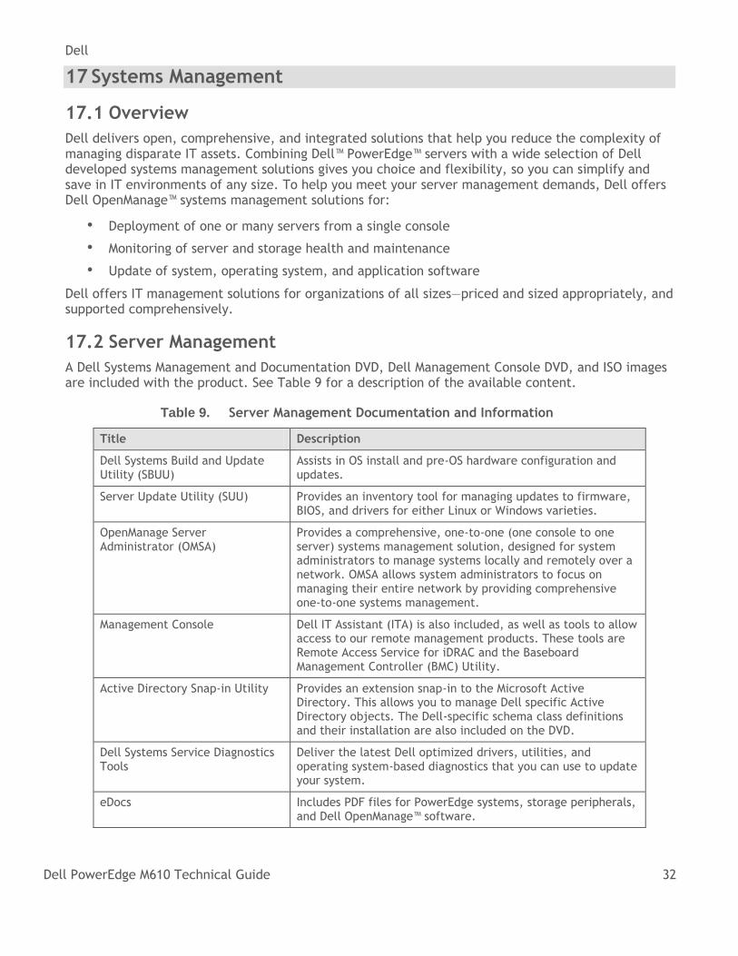
17.2 Server Management
A Dell Systems Management and Documentation DVD, Dell Management Console DVD, and ISO images are included with the product. See Table 9 for a description of the available content.
Table 9. Server Management Documentation and Information
Title Description
Dell Systems Build and Update Utility (SBUU)
Assists in OS install and pre-OS hardware configuration and updates.
Server Update Utility (SUU) Provides an inventory tool for managing updates to firmware, BIOS, and drivers for either Linux or Windows varieties.
OpenManage Server Administrator (OMSA)
Provides a comprehensive, one-to-one (one console to one server) systems management solution, designed for system administrators to manage systems locally and remotely over a network. OMSA allows system administrators to focus on managing their entire network by providing comprehensive one-to-one systems management.
Management Console Dell IT Assistant (ITA) is also included, as well as tools to allow access to our remote management products. These tools are Remote Access Service for iDRAC and the Baseboard Management Controller (BMC) Utility.
Active Directory Snap-in Utility Provides an extension snap-in to the Microsoft Active Directory. This allows you to manage Dell specific Active Directory objects. The Dell-specific schema class definitions and their installation are also included on the DVD.
Dell Systems Service Diagnostics Tools
Deliver the latest Dell optimized drivers, utilities, and operating system-based diagnostics that you can use to update your system.
eDocs Includes PDF files for PowerEdge systems, storage peripherals, and Dell OpenManage™ software.
Dell
Dell PowerEdge M610 Technical Guide 33
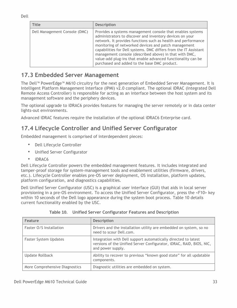
Title Description
Dell Management Console (DMC) Provides a systems management console that enables systems administrators to discover and inventory devices on your network. It provides functions such as health and performance monitoring of networked devices and patch management capabilities for Dell systems. DMC differs from the IT Assistant management console (described above) in that with DMC, value-add plug-ins that enable advanced functionality can be purchased and added to the base DMC product.
17.3 Embedded Server Management
The Dell™ PowerEdge™ M610 circuitry for the next generation of Embedded Server Management. It is Intelligent Platform Management Interface (IPMI) v2.0 compliant. The optional iDRAC (Integrated Dell Remote Access Controller) is responsible for acting as an interface between the host system and its management software and the periphery devices.
The optional upgrade to iDRAC6 provides features for managing the server remotely or in data center lights-out environments.
Advanced iDRAC features require the installation of the optional iDRAC6 Enterprise card.
17.4 Lifecycle Controller and Unified Server Configurator
Embedded management is comprised of interdependent pieces:
• Dell Lifecycle Controller
• Unified Server Configurator
• iDRAC6
Dell Lifecycle Controller powers the embedded management features. It includes integrated and tamper-proof storage for system-management tools and enablement utilities (firmware, drivers, etc.). Lifecycle Controller enables pre-OS server deployment, OS installation, platform updates, platform configuration, and diagnostics capabilities.
Dell Unified Server Configurator (USC) is a graphical user interface (GUI) that aids in local server provisioning in a pre-OS environment. To access the Unified Server Configurator, press the <F10> key within 10 seconds of the Dell logo appearance during the system boot process. Table 10 details current functionality enabled by the USC.
Table 10. Unified Server Configurator Features and Description
Feature Description
Faster O/S Installation Drivers and the installation utility are embedded on system, so no need to scour Dell.com.
Faster System Updates Integration with Dell support automatically directed to latest versions of the Unified Server Configurator, iDRAC, RAID, BIOS, NIC, and power supply.
Update Rollback Ability to recover to previous ―known good state‖ for all updatable components.
More Comprehensive Diagnostics Diagnostic utilities are embedded on system.
Dell
Dell PowerEdge M610 Technical Guide 34
Feature Description
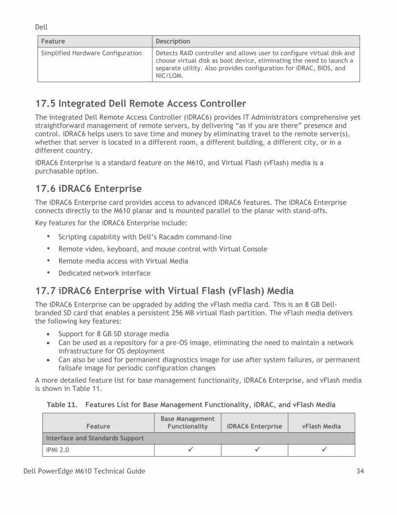
Simplified Hardware Configuration Detects RAID controller and allows user to configure virtual disk and choose virtual disk as boot device, eliminating the need to launch a separate utility. Also provides configuration for iDRAC, BIOS, and NIC/LOM.
17.5 Integrated Dell Remote Access Controller
The integrated Dell Remote Access Controller (iDRAC6) provides IT Administrators comprehensive yet straightforward management of remote servers, by delivering ―as if you are there‖ presence and control. iDRAC6 helps users to save time and money by eliminating travel to the remote server(s), whether that server is located in a different room, a different building, a different city, or in a different country.
iDRAC6 Enterprise is a standard feature on the M610, and Virtual Flash (vFlash) media is a purchasable option.
17.6 iDRAC6 Enterprise
The iDRAC6 Enterprise card provides access to advanced iDRAC6 features. The iDRAC6 Enterprise connects directly to the M610 planar and is mounted parallel to the planar with stand-offs.
Key features for the iDRAC6 Enterprise include:
• Scripting capability with Dell’s Racadm command-line
• Remote video, keyboard, and mouse control with Virtual Console
• Remote media access with Virtual Media
• Dedicated network interface
17.7 iDRAC6 Enterprise with Virtual Flash (vFlash) Media
The iDRAC6 Enterprise can be upgraded by adding the vFlash media card. This is an 8 GB Dell-branded SD card that enables a persistent 256 MB virtual flash partition. The vFlash media delivers the following key features:
Support for 8 GB SD storage media
Can be used as a repository for a pre-OS image, eliminating the need to maintain a network infrastructure for OS deployment
Can also be used for permanent diagnostics image for use after system failures, or permanent failsafe image for periodic configuration changes
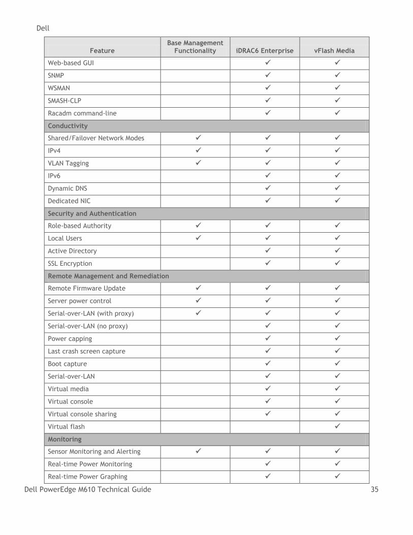
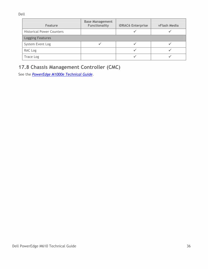
A more detailed feature list for base management functionality, iDRAC6 Enterprise, and vFlash media is shown in Table 11.
Table 11. Features List for Base Management Functionality, iDRAC, and vFlash Media
Feature Base Management
Functionality iDRAC6 Enterprise vFlash Media
Interface and Standards Support
IPMI 2.0
Dell
Dell PowerEdge M610 Technical Guide 35
Feature Base Management
Functionality iDRAC6 Enterprise vFlash Media
Web-based GUI
SNMP
WSMAN
SMASH-CLP
Racadm command-line
Conductivity
Shared/Failover Network Modes
IPv4
VLAN Tagging
IPv6
Dynamic DNS
Dedicated NIC
Security and Authentication
Role-based Authority
Local Users
Active Directory
SSL Encryption
Remote Management and Remediation
Remote Firmware Update
Server power control
Serial-over-LAN (with proxy)
Serial-over-LAN (no proxy)
Power capping
Last crash screen capture
Boot capture
Serial-over-LAN
Virtual media
Virtual console
Virtual console sharing
Virtual flash
Monitoring
Sensor Monitoring and Alerting
Real-time Power Monitoring
Real-time Power Graphing
Dell
Dell PowerEdge M610 Technical Guide 36
Feature Base Management
Functionality iDRAC6 Enterprise vFlash Media
Historical Power Counters
Logging Features
System Event Log
RAC Log
Trace Log
17.8 Chassis Management Controller (CMC)
See the PowerEdge M1000e Technical Guide.
Dell
Dell PowerEdge M610 Technical Guide 37
18 Peripherals
18.1 USB Peripherals
The Dell™ PowerEdge™ M610 supports the following USB devices:
• DVD (bootable; requires two USB ports)
• USB Key (bootable)
• Keyboard (only one USB keyboard is supported)
• Mouse (only one USB mouse is supported)
18.2 External Storage
By use of the appropriate IOMs in the M1000e chassis and mezzanine card(s) in the M610 blade, the following external storage options are available:
Disk Storage Options: o Dell EqualLogic™ PS5000 Series o PowerVault™ NX1950 Unified Storage Solution o PowerVault MD3000i
Dell/EMC fibre channel and/or iSCSI external storage, including: o CX300 o CX3-10c o CX3-20 o CX3-40 o CX3-80 o CX4-120 o CX4-240 o CX4-480 o CX4-960
Dell
Dell PowerEdge M610 Technical Guide 38
Appendix A. Statement of Volatility
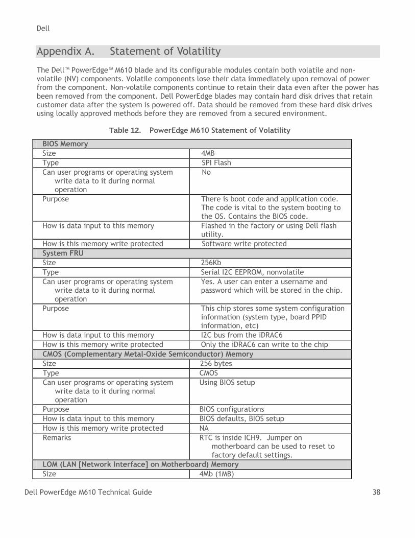
The Dell™ PowerEdge™ M610 blade and its configurable modules contain both volatile and non-volatile (NV) components. Volatile components lose their data immediately upon removal of power from the component. Non-volatile components continue to retain their data even after the power has been removed from the component. Dell PowerEdge blades may contain hard disk drives that retain customer data after the system is powered off. Data should be removed from these hard disk drives using locally approved methods before they are removed from a secured environment.
Table 12. PowerEdge M610 Statement of Volatility
BIOS Memory
Size 4MB
Type SPI Flash
Can user programs or operating system write data to it during normal operation
No
Purpose There is boot code and application code. The code is vital to the system booting to the OS. Contains the BIOS code.
How is data input to this memory Flashed in the factory or using Dell flash utility.
How is this memory write protected Software write protected
System FRU
Size 256Kb
Type Serial I2C EEPROM, nonvolatile
Can user programs or operating system write data to it during normal operation
Yes. A user can enter a username and password which will be stored in the chip.
Purpose This chip stores some system configuration information (system type, board PPID information, etc)
How is data input to this memory I2C bus from the iDRAC6
How is this memory write protected Only the iDRAC6 can write to the chip
CMOS (Complementary Metal-Oxide Semiconductor) Memory
Size 256 bytes
Type CMOS
Can user programs or operating system write data to it during normal operation
Using BIOS setup
Purpose BIOS configurations
How is data input to this memory BIOS defaults, BIOS setup
How is this memory write protected NA
Remarks RTC is inside ICH9. Jumper on motherboard can be used to reset to factory default settings.
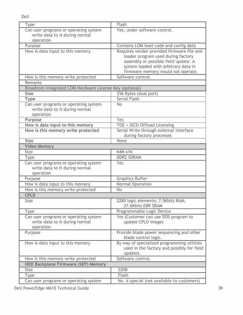
LOM (LAN [Network Interface] on Motherboard) Memory
Size 4Mb (1MB)
Dell
Dell PowerEdge M610 Technical Guide 39
Type Flash
Can user programs or operating system write data to it during normal operation
Yes, under software control.
Purpose Contains LOM boot code and config data
How is data input to this memory Requires vendor provided firmware file and loader program used during factory assembly or possible field update. A system loaded with arbitrary data in firmware memory would not operate.
How is this memory write protected Software control.
Remarks
Broadcom Integrated LOM Hardware License Key (optional)
Size 256 Bytes (dual port)
Type Serial Flash
Can user programs or operating system write data to it during normal operation
No
Purpose Yes
How is data input to this memory TOE + iSCSI Offload Licensing
How is this memory write protected Serial Write through external Interface during factory processes
Size None
Video Memory
Size 64M x16
Type DDR2 SDRAM
Can user programs or operating system write data to it during normal operation
Yes
Purpose Graphics Buffer
How is data input to this memory Normal Operation
How is this memory write protected No
CPLD
Size 2280 logic elements; 7.5Kbits RAM; 27.6Kbits EBR SRAM
Type Programmable Logic Device
Can user programs or operating system write data to it during normal operation
Yes (Customer can use DOS program to update CPLD image)
Purpose Provide blade power sequencing and other blade control logic.
How is data input to this memory By way of specialized programming utilities used in the factory and possibly for field updates.
How is this memory write protected Software control.
HDD Backplane Firmware (SEP) Memory
Size 32KB
Type Flash
Can user programs or operating system No. A special (not available to customers)
Dell
Dell PowerEdge M610 Technical Guide 40
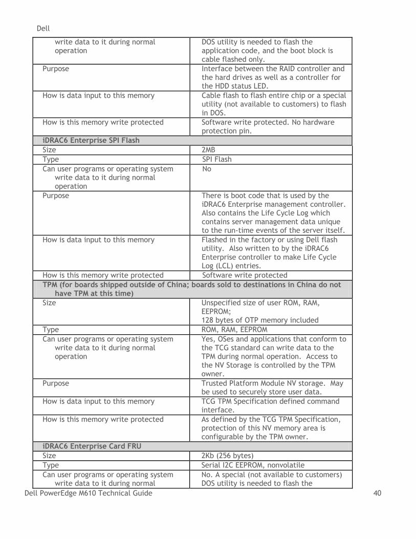
write data to it during normal operation
DOS utility is needed to flash the application code, and the boot block is cable flashed only.
Purpose Interface between the RAID controller and the hard drives as well as a controller for the HDD status LED.
How is data input to this memory Cable flash to flash entire chip or a special utility (not available to customers) to flash in DOS.
How is this memory write protected Software write protected. No hardware protection pin.
iDRAC6 Enterprise SPI Flash
Size 2MB
Type SPI Flash
Can user programs or operating system write data to it during normal operation
No
Purpose There is boot code that is used by the iDRAC6 Enterprise management controller. Also contains the Life Cycle Log which contains server management data unique to the run-time events of the server itself.
How is data input to this memory Flashed in the factory or using Dell flash utility. Also written to by the iDRAC6 Enterprise controller to make Life Cycle Log (LCL) entries.
How is this memory write protected Software write protected
TPM (for boards shipped outside of China; boards sold to destinations in China do not have TPM at this time)
Size Unspecified size of user ROM, RAM, EEPROM; 128 bytes of OTP memory included
Type ROM, RAM, EEPROM
Can user programs or operating system write data to it during normal operation
Yes, OSes and applications that conform to the TCG standard can write data to the TPM during normal operation. Access to the NV Storage is controlled by the TPM owner.
Purpose Trusted Platform Module NV storage. May be used to securely store user data.
How is data input to this memory TCG TPM Specification defined command interface.
How is this memory write protected As defined by the TCG TPM Specification, protection of this NV memory area is configurable by the TPM owner.
iDRAC6 Enterprise Card FRU
Size 2Kb (256 bytes)
Type Serial I2C EEPROM, nonvolatile
Can user programs or operating system write data to it during normal
No. A special (not available to customers) DOS utility is needed to flash the
Dell
Dell PowerEdge M610 Technical Guide 41
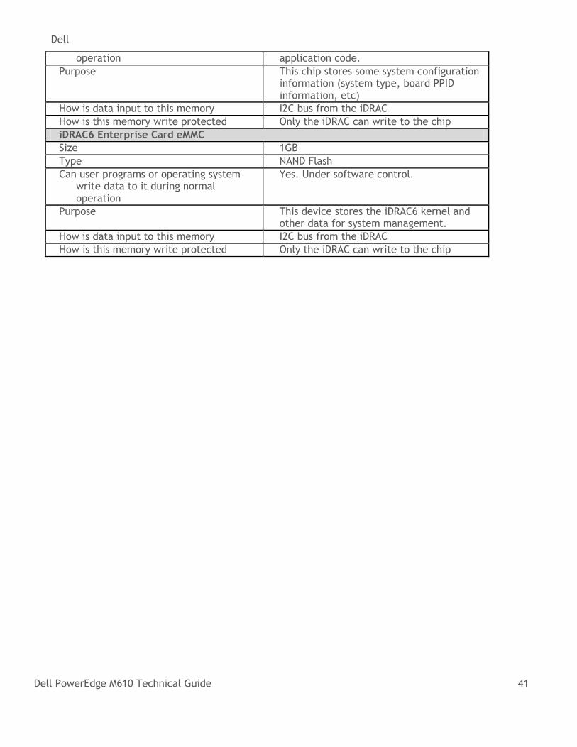
operation application code.
Purpose This chip stores some system configuration information (system type, board PPID information, etc)
How is data input to this memory I2C bus from the iDRAC
How is this memory write protected Only the iDRAC can write to the chip
iDRAC6 Enterprise Card eMMC
Size 1GB
Type NAND Flash
Can user programs or operating system write data to it during normal operation
Yes. Under software control.
Purpose This device stores the iDRAC6 kernel and other data for system management.
How is data input to this memory I2C bus from the iDRAC
How is this memory write protected Only the iDRAC can write to the chip
Dell
Dell PowerEdge M610 Technical Guide 42
Appendix B. Certifications
Regulatory Certifications B 1.
Regulatory compliance certificates can be located at the following sites:
http://www.dell.com/content/topics/global.aspx/about_dell/values/regulatory_compliance/dec_conform?c=us&l=en&s=corp
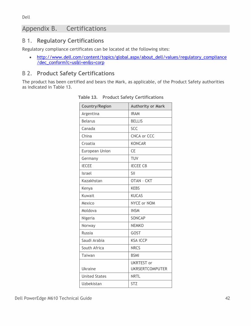
Product Safety Certifications B 2.
The product has been certified and bears the Mark, as applicable, of the Product Safety authorities as indicated in Table 13.
Table 13. Product Safety Certifications
Country/Region Authority or Mark
Argentina IRAM
Belarus BELLIS
Canada SCC
China CNCA or CCC
Croatia KONCAR
European Union CE
Germany TUV
IECEE IECEE CB
Israel SII
Kazakhstan OTAN – CKT
Kenya KEBS
Kuwait KUCAS
Mexico NYCE or NOM
Moldova INSM
Nigeria SONCAP
Norway NEMKO
Russia GOST
Saudi Arabia KSA ICCP
South Africa NRCS
Taiwan BSMI
Ukraine
UKRTEST or
UKRSERTCOMPUTER
United States NRTL
Uzbekistan STZ
Dell
Dell PowerEdge M610 Technical Guide 43
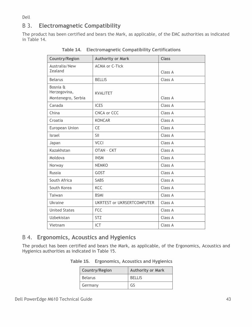
Electromagnetic Compatibility B 3.
The product has been certified and bears the Mark, as applicable, of the EMC authorities as indicated in Table 14.
Table 14. Electromagnetic Compatibility Certifications
Country/Region Authority or Mark Class
Australia/New Zealand
ACMA or C-Tick
Class A
Belarus BELLIS Class A
Bosnia & Herzegovina,
Montenegro, Serbia
KVALITET Class A
Canada ICES Class A
China CNCA or CCC Class A
Croatia KONCAR Class A
European Union CE Class A
Israel SII Class A
Japan VCCI Class A
Kazakhstan OTAN – CKT Class A
Moldova INSM Class A
Norway NEMKO Class A
Russia GOST Class A
South Africa SABS Class A
South Korea KCC Class A
Taiwan BSMI Class A
Ukraine UKRTEST or UKRSERTCOMPUTER Class A
United States FCC Class A
Uzbekistan STZ Class A
Vietnam ICT Class A
Ergonomics, Acoustics and Hygienics B 4.
The product has been certified and bears the Mark, as applicable, of the Ergonomics, Acoustics and Hygienics authorities as indicated in Table 15.
Table 15. Ergonomics, Acoustics and Hygienics
Country/Region Authority or Mark
Belarus BELLIS
Germany GS
Dell
Dell PowerEdge M610 Technical Guide 44
Country/Region Authority or Mark
Russia GOST
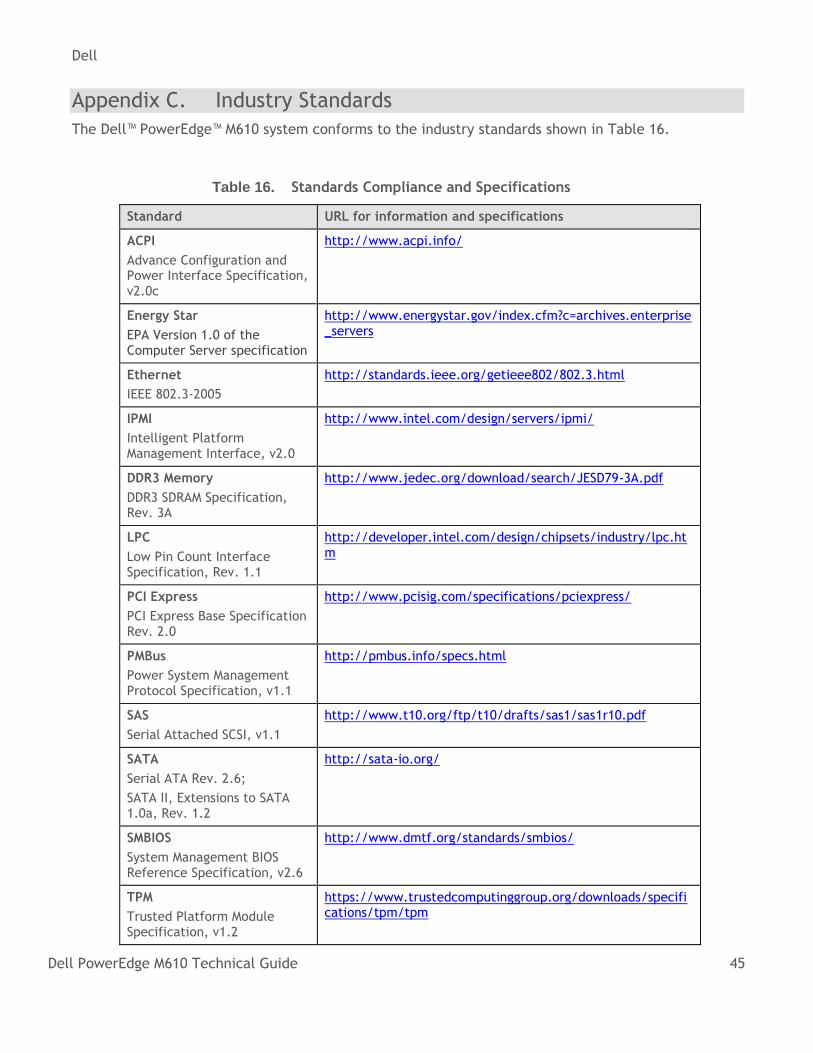
Dell
Dell PowerEdge M610 Technical Guide 45
Appendix C. Industry Standards
The Dell™ PowerEdge™ M610 system conforms to the industry standards shown in Table 16.
Table 16. Standards Compliance and Specifications
Standard URL for information and specifications
ACPI
Advance Configuration and Power Interface Specification, v2.0c
http://www.acpi.info/
Energy Star
EPA Version 1.0 of the Computer Server specification
http://www.energystar.gov/index.cfm?c=archives.enterprise_servers
Ethernet
IEEE 802.3-2005
http://standards.ieee.org/getieee802/802.3.html
IPMI
Intelligent Platform Management Interface, v2.0
http://www.intel.com/design/servers/ipmi/
DDR3 Memory
DDR3 SDRAM Specification, Rev. 3A
http://www.jedec.org/download/search/JESD79-3A.pdf
LPC
Low Pin Count Interface Specification, Rev. 1.1
http://developer.intel.com/design/chipsets/industry/lpc.htm
PCI Express
PCI Express Base Specification Rev. 2.0
http://www.pcisig.com/specifications/pciexpress/
PMBus
Power System Management Protocol Specification, v1.1
http://pmbus.info/specs.html
SAS
Serial Attached SCSI, v1.1
http://www.t10.org/ftp/t10/drafts/sas1/sas1r10.pdf
SATA
Serial ATA Rev. 2.6;
SATA II, Extensions to SATA 1.0a, Rev. 1.2
http://sata-io.org/
SMBIOS
System Management BIOS Reference Specification, v2.6
http://www.dmtf.org/standards/smbios/
TPM
Trusted Platform Module Specification, v1.2
https://www.trustedcomputinggroup.org/downloads/specifications/tpm/tpm
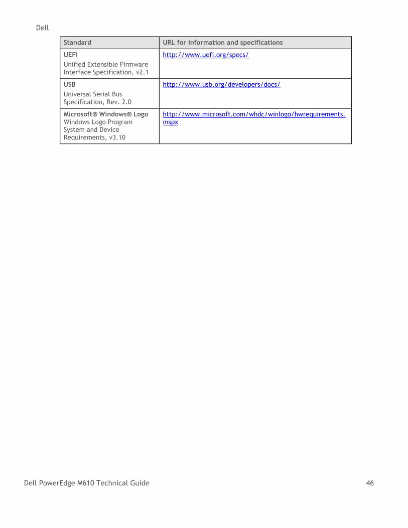
Dell
Dell PowerEdge M610 Technical Guide 46
Standard URL for information and specifications
UEFI
Unified Extensible Firmware Interface Specification, v2.1
http://www.uefi.org/specs/
USB
Universal Serial Bus Specification, Rev. 2.0
http://www.usb.org/developers/docs/
Microsoft® Windows® Logo Windows Logo Program System and Device Requirements, v3.10
http://www.microsoft.com/whdc/winlogo/hwrequirements.mspx