Embed Size (px)
Citation preview
PowerEdge T610
Technical Guide
The PowerEdge
T610 server delivers balanced high performance,
energy efficiency and room for growth.
Dell
PowerEdge T610 Technical Guide
ii
This document is for informational purposes only. Dell reserves the right to make changes without further notice to any products herein. The content provided is as is and without express or implied warranties of any kind.
Dell, PowerEdge, OpenManage, and ReadyRails are trademarks of Dell, Inc. Citrix and XenServer are registered trademarks of Citrix Systems, Inc. and/or one or more of its subsidiaries, and may be registered in the United States Patent and Trademark Office and in other countries. Intel, Xeon, and SpeedStep are registered trademarks and MMX is a trademark of Intel Corporation in the U.S. and other countries. Broadcom is a registered trademark and NetXtreme is a trademark of Broadcom Corporation and/or its affiliates in the United States, certain other countries and/or the EU. Emulex is a registered trademark of Emulex Corporation. ENERGY STAR is a registered trademark of the U.S. Environmental Protection Agency. eToken is a trademark of Aladdin Knowledge Systems, Ltd. Linux is a registered trademark of Linus Torvalds. Matrox is a registered trademark of Matrox Electronic Systems Ltd. Microsoft, Windows, Windows Server, SQL Server, Hyper-V, and BitLocker are either registered trademarks or trademarks of Microsoft Corporation in the United States and/or other countries. Novell and SUSE are registered trademarks of Novell, Inc. in the United States and other countries. Oracle is a registered trademark and Solaris is a trademark of Oracle Corporation and/or its affiliates. Red Hat is a registered trademark of Red Hat, Inc. in the United States and other countries. Symantec is a trademark owned by Symantec Corporation or its affiliates in the U.S. and other countries. VMware and vSphere are registered trademarks and ESX and ESXi are trademarks of VMware, Inc. in the United States and/or other jurisdictions. Other trademarks and trade names may be used in this document to refer to either the entities claiming the marks and names or their products. Dell disclaims proprietary interest in the marks and names of others.
©Copyright 2012 Dell Inc. All rights reserved. Reproduction or translation of any part of this work beyond that permitted by U.S. copyright laws without the written permission of Dell Inc. is unlawful and strictly forbidden.
December 2012 | Version 5.0
Dell
PowerEdge T610 Technical Guide iii
Table of Contents
1 Product Comparison ........................................................................................... 7 1.1 Overview .................................................................................................. 7
1.1.1 Customer-Inspired Design ......................................................................... 7 1.1.2 Energy Efficient .................................................................................... 7 1.1.3 Enhanced Virtualization ........................................................................... 7 1.1.4 Easy to Manage ..................................................................................... 7 1.1.5 Dell Services ........................................................................................ 8
1.2 Comparison ............................................................................................... 8 2 Key Technologies ............................................................................................. 10
2.1 Overview ................................................................................................ 10 2.2 Detailed Information ................................................................................... 10
3 System Overview ............................................................................................. 11 4 Mechanical .................................................................................................... 13
4.1 Chassis Description ..................................................................................... 13 4.2 Dimensions and Weight ................................................................................ 13 4.3 Front Panel View and Features ....................................................................... 13 4.4 Back Panel View and Features ....................................................................... 15 4.5 Power Supply Indicators ............................................................................... 15 4.6 NIC Indicators ........................................................................................... 16 4.7 Internal Chassis Views ................................................................................. 16 4.8 Rails and Cable Management ......................................................................... 16 4.9 Fans ...................................................................................................... 17 4.10 LCD Control Panel ...................................................................................... 17 4.11 Security .................................................................................................. 18
4.11.1 Cover Latch ....................................................................................... 18 4.11.2 Bezel ............................................................................................... 18 4.11.3 Hard Drive ......................................................................................... 18 4.11.4 TPM ................................................................................................. 18 4.11.5 Power Off Security ............................................................................... 19 4.11.6 Intrusion Alert .................................................................................... 19 4.11.7 Secure Mode ...................................................................................... 19
4.12 USB Peripherals ......................................................................................... 19 4.13 Battery ................................................................................................... 19 4.14 Field Replaceable Units (FRU) ........................................................................ 19 4.15 User Accessible Jumpers, Sockets, and Connectors ............................................... 19
5 Power, Thermal, and Acoustic ............................................................................. 20 5.1 Power Efficiencies ..................................................................................... 20 5.2 Main Power Supply ..................................................................................... 20 5.3 Power Supply Specifications .......................................................................... 21 5.4 Heat Dissipation ........................................................................................ 21 5.5 Environmental Specifications ......................................................................... 22 5.6 Power Consumption Testing .......................................................................... 23 5.7 Maximum Input Amps .................................................................................. 23 5.8 Energy Smart Enablement............................................................................. 23 5.9 ENERGY STAR Compliance ............................................................................ 24 5.10 Acoustics ................................................................................................ 24
6 Processors ..................................................................................................... 25
Dell
PowerEdge T610 Technical Guide iv
6.1 Overview ................................................................................................ 25 6.2 Features ................................................................................................. 25 6.3 Supported Processors .................................................................................. 26 6.4 Processor Configurations .............................................................................. 27
6.4.1 Single Processor Configuration ................................................................. 27 6.4.2 Processor Power Voltage Regulation Modules (EVRD 11.1) ................................. 27
6.5 Processor Installation .................................................................................. 27 7 Memory ........................................................................................................ 28
7.1 Overview ................................................................................................ 28 7.2 DIMMs Supported ....................................................................................... 28
7.2.1 Memory Modes .................................................................................... 28 7.2.2 DIMM Population Rules ........................................................................... 29
7.3 Speed .................................................................................................... 29 7.4 DIMM Slots ............................................................................................... 30 7.5 Low Voltage DIMMs ..................................................................................... 30 7.6 Mirroring ................................................................................................. 30 7.7 Sparing ................................................................................................... 31 7.8 Memory Scrubbing...................................................................................... 31 7.9 Advanced ECC (Lockstep) Mode ...................................................................... 31 7.10 Optimizer (Independent Channel) Mode ............................................................ 31 7.11 Supported Configurations ............................................................................. 31
8 Chipset ........................................................................................................ 32 8.1 Overview ................................................................................................ 32 8.2 Intel I/O Hub (IOH) ..................................................................................... 32 8.3 IOH QuickPath Interconnect (QPI) ................................................................... 32 8.4 Intel Direct Media Interface (DMI) ................................................................... 32 8.5 PCI Express .............................................................................................. 32 8.6 Intel I/O Controller Hub 9 (ICH9) .................................................................... 33
9 BIOS ............................................................................................................ 34 9.1 Overview ................................................................................................ 34 9.2 Supported ACPI States ................................................................................. 34
9.3 I2C (Inter-Integrated Circuit) ......................................................................... 34
10 Embedded NICs/LAN on Motherboard (LOM) ............................................................. 36 11 PCI Slots ....................................................................................................... 37
11.1 Overview ................................................................................................ 37 11.2 Quantities and Priorities .............................................................................. 37 11.3 PCI Card Dimensions ................................................................................... 37
12 Storage ........................................................................................................ 38 12.1 Overview ................................................................................................ 38 12.2 Internal Hard Disk Drives .............................................................................. 38
12.2.1 Hard Disk Drive Carriers ......................................................................... 39 12.2.2 Empty Drive Bays ................................................................................. 39 12.2.3 Hard Drive LED Indicators ....................................................................... 39
12.3 RAID Configurations .................................................................................... 39 12.4 Storage Controllers .................................................................................... 41
12.4.1 SAS 6/iR ........................................................................................... 41 12.4.2 PERC 6/i ........................................................................................... 41 12.4.3 PERC H200 ......................................................................................... 41 12.4.4 PERC H700 ......................................................................................... 42
12.5 Optical Drives ........................................................................................... 43
Dell
PowerEdge T610 Technical Guide v
12.6 Tape Drives.............................................................................................. 43 12.7 External Storage Support .............................................................................. 43
13 Video ........................................................................................................... 44 14 Rack Information ............................................................................................. 45
14.1 Overview ................................................................................................ 45 14.2 Rails ...................................................................................................... 45 14.3 Cable Management Arm (CMA) ....................................................................... 47 14.4 Rack View ............................................................................................... 47
15 Operating Systems ........................................................................................... 49 16 Systems Management ........................................................................................ 50
16.1 Overview ................................................................................................ 50 16.2 Server Management .................................................................................... 50 16.3 Embedded Server Management....................................................................... 51 16.4 Dell Lifecycle Controller and Unified Server Configurator ....................................... 51 16.5 Integrated Dell Remote Access Controller .......................................................... 51 16.6 iDRAC Express ........................................................................................... 52 16.7 iDRAC6 Enterprise ...................................................................................... 52 16.8 iDRAC6 Enterprise with Virtual Flash (vFlash) Media .............................................. 52
17 Peripherals .................................................................................................... 55 Appendix A. Statement of Volatility .......................................................................... 56 Appendix B. Certifications ..................................................................................... 60
Regulatory Certifications ............................................................................. 60 A 1. Product Safety Certifications ......................................................................... 60 A 2. Electromagnetic Compatibility ....................................................................... 61 A 3. Ergonomics, Acoustics and Hygienics ................................................................ 61 A 4.
Appendix C. Additional Information and Options ........................................................... 63
Tables
Comparison of PowerEdge T610 to T410 and T710 ............................................... 8 Table 1. Product Features Summary ........................................................................ 11 Table 2. Chassis Dimensions .................................................................................. 13 Table 3. Power Supply Status ................................................................................ 15 Table 4. Power Supply Specifications ....................................................................... 21 Table 5. Environmental Specifications ...................................................................... 22 Table 6. Acoustical Performance (2.5” HDD System) ..................................................... 24 Table 7. Acoustical Performance (3.5” HDD System) ..................................................... 24 Table 8. Intel Xeon Processor 5500 and 5600 Series Features ........................................... 25 Table 9.
Supported Processors ............................................................................... 26 Table 10. Supported Hard Drives .............................................................................. 38 Table 11. Factory RAID Configurations ....................................................................... 40 Table 12. Storage Card Support Matrix ....................................................................... 42 Table 13. Graphics Video Modes .............................................................................. 44 Table 14. Supported Racks ..................................................................................... 46 Table 15. Rail Adjustability Ranges and Depth ............................................................. 46 Table 16. Unified Server Configurator Features and Description......................................... 51 Table 17. Features List for Base Management Functionality, iDRAC, and vFlash Media .............. 53 Table 18. T610 Volatility Table ............................................................................... 56 Table 19. Product Safety Certifications ...................................................................... 60 Table 20.
Dell
PowerEdge T610 Technical Guide vi
Electromagnetic Compatibility Certifications ................................................... 61 Table 21. Ergonomics, Acoustics and Hygienics ............................................................. 62 Table 22. Industry Standards .................................................................................. 63 Table 23.
Figures
Front View (Tower Configuration) ................................................................ 14 Figure 1. Front View (Rack Configuration) .................................................................. 14 Figure 2. Back View ............................................................................................ 15 Figure 3. Internal Chassis View ............................................................................... 16 Figure 4. Fans and Cooling Shroud ........................................................................... 17 Figure 5. LCD Control Panel ................................................................................... 18 Figure 6. Power Supplies ...................................................................................... 21 Figure 7. Memory Channel Layout ............................................................................ 29 Figure 8. Dell 2.5” Hard Drive Carrier ....................................................................... 39 Figure 9.
T610 ReadyRails Sliding Rails with Optional CMA ............................................ 45 Figure 10. 2U Threaded Rack Adapter Brackets Kit ...................................................... 46 Figure 11. T610 Mounted in C1 Sliding Rails ............................................................... 47 Figure 12. T610 CMA Mounted on the Side Opposite the Power Supplies (Recommended) ......... 48 Figure 13.
Dell
PowerEdge T610 Technical Guide 7
1 Product Comparison
1.1 Overview
The Dell™ PowerEdge™ T610 is a tower form-factor server designed to deliver the highest levels of performance, availability and expandability in a two-socket server. Featuring up to two powerful
Intel® processors, the T610 offers large memory capacity, high I/O bandwidth and extensive storage capacity, satisfying today’s compute requirements and also allowing it to grow as your business grows. The T610 features straightforward systems management to ease IT administration and energy efficiency to help manage power consumption and budget.
1.1.1 Customer-Inspired Design
Inspired by our customers, the T610 is built to simplify daily operations and maximize uptime. Logical component layout and power supply placement provide a straightforward installation and deployment experience. Dell PowerEdge servers provide a graphical and interactive LCD panel in the front of the server, used for monitoring system health, assessing alerts and performing configuration. The T610 has an AC power meter and ambient temperature thermometer built into the server which can be monitored on the display without any software tools. Moreover, the T610 takes advantage of Dell’s system commonality. Once your IT managers learn one system, they understand how to manage all of Dell’s 11th generation servers.
1.1.2 Energy Efficient
The T610 helps reduce power consumption while delivering higher performance than previous generations of Dell tower servers. Enhancements include the latest highly efficient, standards-based Energy Smart components, updated energy-efficient power supply units (PSUs) and power and thermal management that can be automated at the convenience of the system administrator. The T610 can help to reduce power consumption and budget and ease the day of the systems administrator as well.
1.1.3 Enhanced Virtualization
Featuring the Intel® Xeon® processor 5500 and 5600 series, up to 100% more memory capacity than the previous server generations, integrated I/O and embedded hypervisors, the Dell PowerEdge T610 delivers better overall system performance and greater virtual machine-per-server capacity than ever before.
With optional factory-integrated virtualization capabilities, tailored solutions can be created, allowing you to streamline deployment and reduce the time taken to deliver new solutions to your user base. For example, choose your hypervisor from market leaders such as VMware, Citrix and Microsoft, and enable virtualization with a few mouse clicks.
1.1.4 Easy to Manage
The Dell OpenManage™ portfolio of systems management offerings streamline and simplify
operational tasks throughout the complete server lifecycle, from initial provisioning and deployment
to ongoing monitoring, troubleshooting and problem resolution, to applying BIOS and driver updates
and pulling administrative reports. Based on open standards, Dell OpenManage™ systems management
capabilities can be applied locally and to remote systems, remaining available out-of-band,
independent of the operating system (OS) state, and functional even in virtualized (hypervisor)
environments. Designed to deliver comprehensive lifecycle management, the OpenManage portfolio
Dell
PowerEdge T610 Technical Guide 8
of systems management solutions help you to save time, save money and reduce the complexity of
managing your IT infrastructure.
1.1.5 Dell Services
Dell Services can help reduce IT complexity, lower costs and eliminate inefficiencies by making IT and business solutions work harder for you. The Dell Services team takes a holistic view of your needs and designs solutions for your environment and business objectives, leveraging proven delivery methods, local talent, and in-depth domain knowledge.
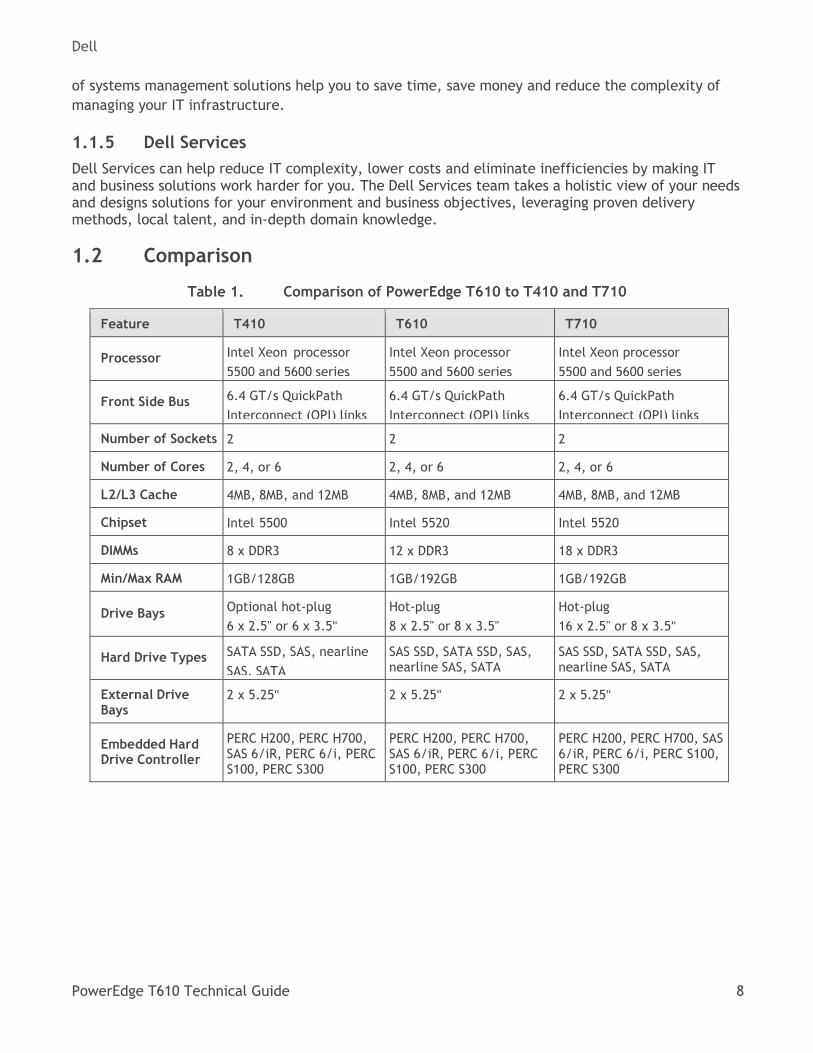
1.2 Comparison
Comparison of PowerEdge T610 to T410 and T710 Table 1.
Feature T410 T610 T710
Processor Intel Xeon processor
5500 and 5600 series
Intel Xeon processor
5500 and 5600 series
Intel Xeon processor
5500 and 5600 series
Front Side Bus 6.4 GT/s QuickPath
Interconnect (QPI) links
6.4 GT/s QuickPath
Interconnect (QPI) links
6.4 GT/s QuickPath
Interconnect (QPI) links
Number of Sockets 2 2 2
Number of Cores 2, 4, or 6 2, 4, or 6 2, 4, or 6
L2/L3 Cache 4MB, 8MB, and 12MB 4MB, 8MB, and 12MB 4MB, 8MB, and 12MB
Chipset Intel 5500 Intel 5520 Intel 5520
DIMMs 8 x DDR3 12 x DDR3 18 x DDR3
Min/Max RAM 1GB/128GB 1GB/192GB 1GB/192GB
Drive Bays Optional hot-plug
6 x 2.5" or 6 x 3.5"
Hot-plug
8 x 2.5" or 8 x 3.5"
Hot-plug
16 x 2.5" or 8 x 3.5"
Hard Drive Types SATA SSD, SAS, nearline
SAS, SATA
SAS SSD, SATA SSD, SAS, nearline SAS, SATA
SAS SSD, SATA SSD, SAS, nearline SAS, SATA
External Drive Bays
2 x 5.25" 2 x 5.25" 2 x 5.25"
Embedded Hard Drive Controller
PERC H200, PERC H700, SAS 6/iR, PERC 6/i, PERC S100, PERC S300
PERC H200, PERC H700, SAS 6/iR, PERC 6/i, PERC S100, PERC S300
PERC H200, PERC H700, SAS 6/iR, PERC 6/i, PERC S100, PERC S300
Dell
PowerEdge T610 Technical Guide 9
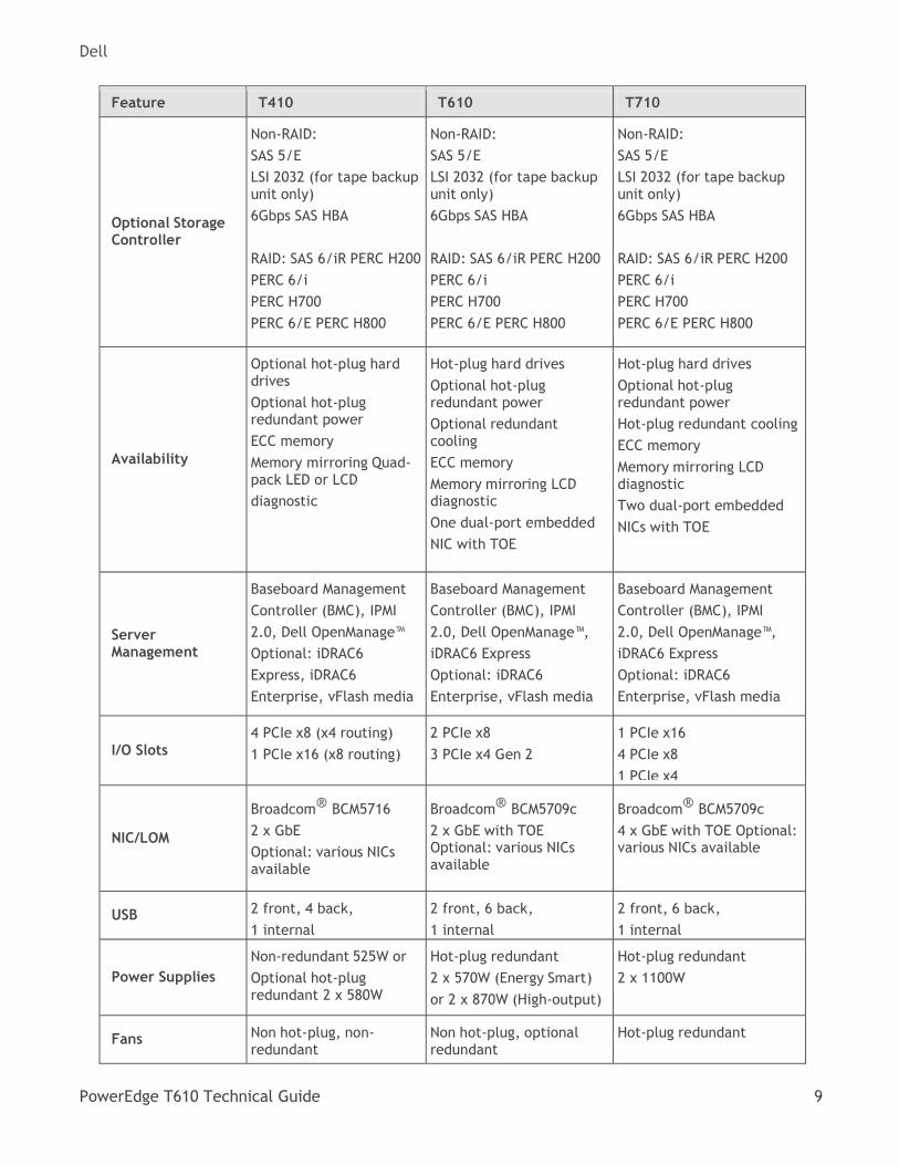
Feature T410 T610 T710
Optional Storage Controller
Non-RAID:
SAS 5/E
LSI 2032 (for tape backup unit only)
6Gbps SAS HBA
RAID: SAS 6/iR PERC H200
PERC 6/i
PERC H700
PERC 6/E PERC H800
Non-RAID:
SAS 5/E
LSI 2032 (for tape backup unit only)
6Gbps SAS HBA
RAID: SAS 6/iR PERC H200
PERC 6/i
PERC H700
PERC 6/E PERC H800
Non-RAID:
SAS 5/E
LSI 2032 (for tape backup unit only)
6Gbps SAS HBA
RAID: SAS 6/iR PERC H200
PERC 6/i
PERC H700
PERC 6/E PERC H800
Availability
Optional hot-plug hard drives
Optional hot-plug redundant power
ECC memory
Memory mirroring Quad-pack LED or LCD
diagnostic
Hot-plug hard drives
Optional hot-plug redundant power
Optional redundant cooling
ECC memory
Memory mirroring LCD diagnostic
One dual-port embedded
NIC with TOE
Hot-plug hard drives
Optional hot-plug redundant power
Hot-plug redundant cooling
ECC memory
Memory mirroring LCD diagnostic
Two dual-port embedded
NICs with TOE
Server Management
Baseboard Management
Controller (BMC), IPMI
2.0, Dell OpenManage™
Optional: iDRAC6
Express, iDRAC6
Enterprise, vFlash media
Baseboard Management
Controller (BMC), IPMI
2.0, Dell OpenManage™,
iDRAC6 Express
Optional: iDRAC6
Enterprise, vFlash media
Baseboard Management
Controller (BMC), IPMI
2.0, Dell OpenManage™,
iDRAC6 Express
Optional: iDRAC6
Enterprise, vFlash media
I/O Slots
4 PCIe x8 (x4 routing)
1 PCIe x16 (x8 routing)
2 PCIe x8
3 PCIe x4 Gen 2
1 PCIe x16
4 PCIe x8
1 PCIe x4
NIC/LOM
Broadcom® BCM5716
2 x GbE
Optional: various NICs available
Broadcom® BCM5709c
2 x GbE with TOE Optional: various NICs available
Broadcom® BCM5709c
4 x GbE with TOE Optional: various NICs available
USB 2 front, 4 back,
1 internal
2 front, 6 back,
1 internal
2 front, 6 back,
1 internal
Power Supplies
Non-redundant 525W or
Optional hot-plug redundant 2 x 580W
Hot-plug redundant
2 x 570W (Energy Smart)
or 2 x 870W (High-output)
Hot-plug redundant
2 x 1100W
Fans Non hot-plug, non- redundant
Non hot-plug, optional redundant
Hot-plug redundant
Dell
PowerEdge T610 Technical Guide 10
2 Key Technologies
2.1 Overview
Key features of the PowerEdge T610 include dual Intel® Xeon® 5500 and 5600 series quad-core and
six-core processors, DDR3 memory, Intel® 5520 I/O Hub (IOH) with QuickPath architecture, dual-port Gigabit Ethernet controller with TOE, PCI Express Generation 2, iDRAC6 with integrated video controller, internal SD Module, iDRAC6 Express, and optional iDRAC6 Enterprise.
2.2 Detailed Information
The Intel® Xeon® processor 5500 and 5600 series is designed specifically for servers and workstation applications. The processor features quad-core and six-core processing to maximize performance and performance/watt. Refer to section 6 for more details.
Dell
PowerEdge T610 Technical Guide 11
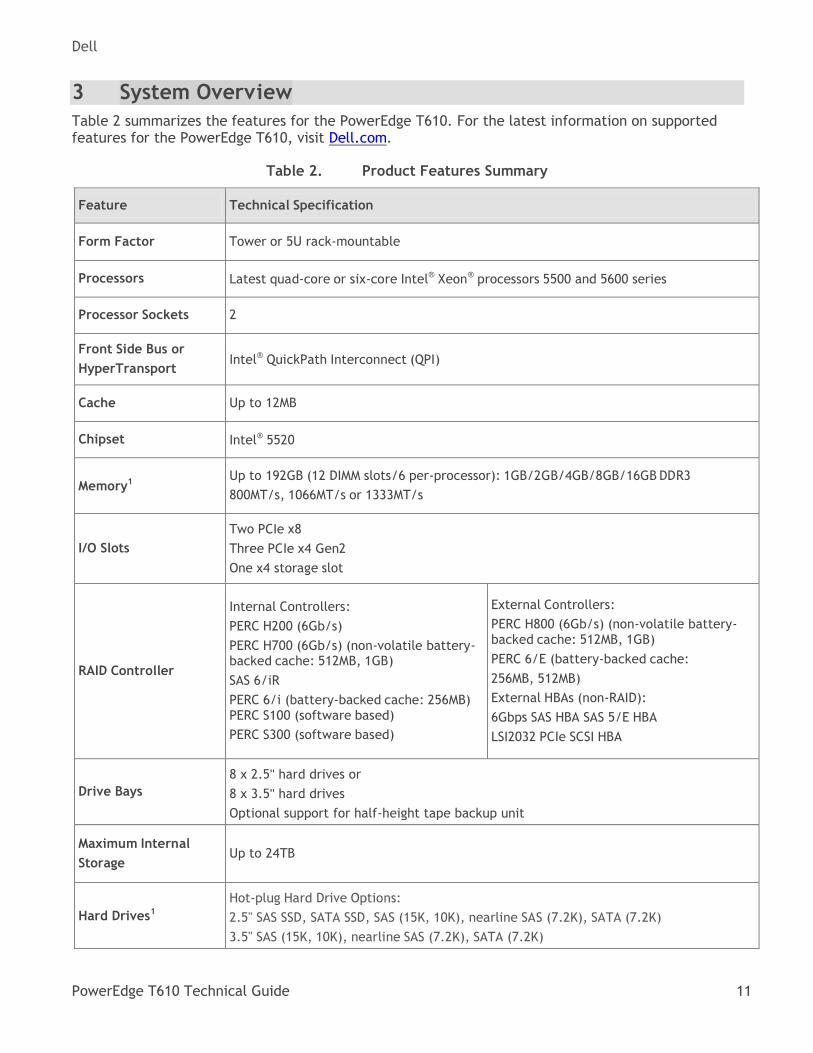
3 System Overview
Table 2 summarizes the features for the PowerEdge T610. For the latest information on supported features for the PowerEdge T610, visit Dell.com.
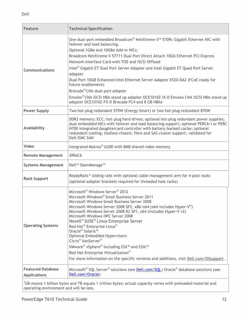
Product Features Summary Table 2.
Feature Technical Specification
Form Factor Tower or 5U rack-mountable
Processors Latest quad-core or six-core Intel® Xeon® processors 5500 and 5600 series
Processor Sockets 2
Front Side Bus or
HyperTransport Intel® QuickPath Interconnect (QPI)
Cache Up to 12MB
Chipset Intel® 5520
Memory1
Up to 192GB (12 DIMM slots/6 per-processor): 1GB/2GB/4GB/8GB/16GB DDR3
800MT/s, 1066MT/s or 1333MT/s
I/O Slots
Two PCIe x8
Three PCIe x4 Gen2
One x4 storage slot
RAID Controller
Internal Controllers:
PERC H200 (6Gb/s)
PERC H700 (6Gb/s) (non-volatile battery-backed cache: 512MB, 1GB)
SAS 6/iR
PERC 6/i (battery-backed cache: 256MB) PERC S100 (software based)
PERC S300 (software based)
External Controllers:
PERC H800 (6Gb/s) (non-volatile battery-backed cache: 512MB, 1GB)
PERC 6/E (battery-backed cache:
256MB, 512MB)
External HBAs (non-RAID):
6Gbps SAS HBA SAS 5/E HBA
LSI2032 PCIe SCSI HBA
Drive Bays
8 x 2.5" hard drives or
8 x 3.5" hard drives
Optional support for half-height tape backup unit
Maximum Internal
Storage Up to 24TB
Hard Drives1
Hot-plug Hard Drive Options:
2.5" SAS SSD, SATA SSD, SAS (15K, 10K), nearline SAS (7.2K), SATA (7.2K)
3.5" SAS (15K, 10K), nearline SAS (7.2K), SATA (7.2K)
Dell
PowerEdge T610 Technical Guide 12
Feature Technical Specification
Communications
One dual-port embedded Broadcom® NetXtreme II™ 5709c Gigabit Ethernet NIC with failover and load balancing.
Optional 1GBe and 10GBe Add-in NICs:
Broadcom NetXtreme II 57711 Dual Port Direct Attach 10Gb Ethernet PCI-Express
Network Interface Card with TOE and iSCSI Offload
Intel® Gigabit ET Dual Port Server Adapter and Intel Gigabit ET Quad Port Server
Adapter
Dual Port 10GB Enhanced Intel Ethernet Server Adapter X520-DA2 (FCoE ready for future enablement)
Brocade® CNA dual-port adapter
Emulex® CNA iSCSI HBA stand up adapter OCE10102-IX-D Emulex CNA iSCSI HBA stand up adapter OCE10102-FX-D Brocade FC4 and 8 GB HBAs
Power Supply Two hot-plug redundant 570W (Energy Smart) or two hot-plug redundant 870W
Availability
DDR3 memory; ECC; hot-plug hard drives; optional hot-plug redundant power supplies; dual embedded NICs with failover and load balancing support; optional PERC6/i or PERC H700 integrated daughtercard controller with battery-backed cache; optional redundant cooling; toolless chassis; fibre and SAS cluster support; validated for Dell/EMC SAN
Video Integrated Matrox® G200 with 8MB shared video memory
Remote Management iDRAC6
Systems Management Dell™ OpenManage™
Rack Support ReadyRails™ sliding rails with optional cable management arm for 4-post racks
(optional adapter brackets required for threaded hole racks)
Operating Systems
Microsoft® Windows Server® 2012
Microsoft Windows® Small Business Server 2011 Microsoft Windows Small Business Server 2008
Microsoft Windows Server 2008 SP2, x86/x64 (x64 includes Hyper-V®) Microsoft Windows Server 2008 R2 SP1, x64 (includes Hyper-V v2) Microsoft Windows HPC Server 2008
Novell® SUSE® Linux Enterprise Server
Red Hat® Enterprise Linux®
Oracle® Solaris™ Optional Embedded Hypervisors:
Citrix® XenServer®
VMware® vSphere® including ESX™ and ESXi™
Red Hat Enterprise Virtualization®
For more information on the specific versions and additions, visit Dell.com/OSsupport.
Featured Database
Applications
Microsoft® SQL Server® solutions (see Dell.com/SQL) Oracle® database solutions (see Dell.com/Oracle)
1GB means 1 billion bytes and TB equals 1 trillion bytes; actual capacity varies with preloaded material and operating environment and will be less.
Dell
PowerEdge T610 Technical Guide 13
4 Mechanical
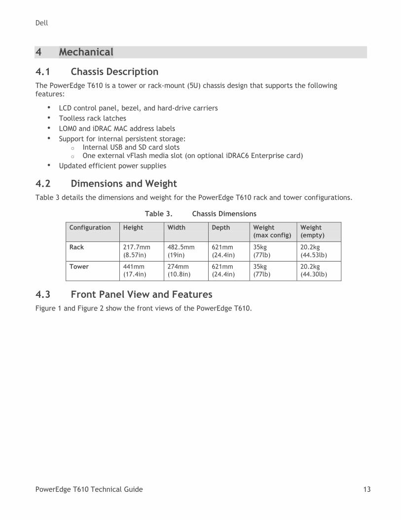
4.1 Chassis Description
The PowerEdge T610 is a tower or rack-mount (5U) chassis design that supports the following features:
• LCD control panel, bezel, and hard-drive carriers
• Toolless rack latches
• LOM0 and iDRAC MAC address labels
• Support for internal persistent storage: o Internal USB and SD card slots o One external vFlash media slot (on optional iDRAC6 Enterprise card)
• Updated efficient power supplies
4.2 Dimensions and Weight
Table 3 details the dimensions and weight for the PowerEdge T610 rack and tower configurations.
Chassis Dimensions Table 3.
Configuration Height Width Depth Weight (max config)
Weight (empty)
Rack 217.7mm
(8.57in)
482.5mm
(19in)
621mm
(24.4in)
35kg
(77lb)
20.2kg
(44.53lb)
Tower 441mm (17.4in)
274mm (10.8in)
621mm (24.4in)
35kg (77lb)
20.2kg (44.30lb)
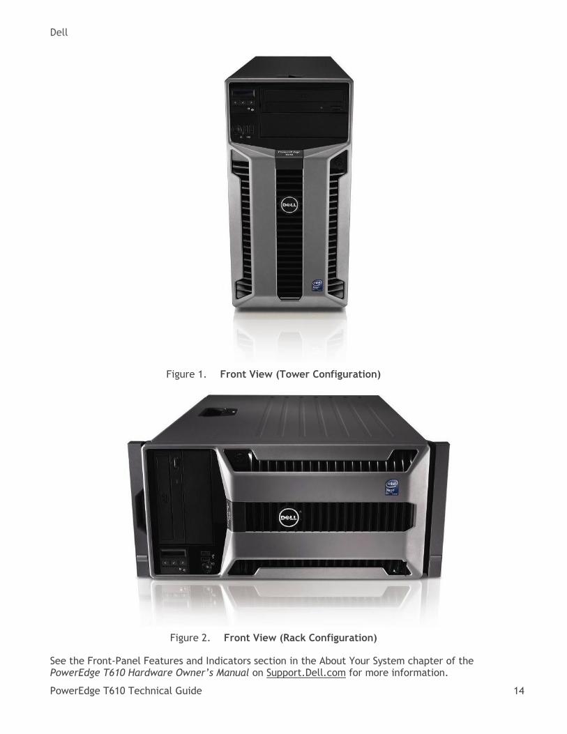
4.3 Front Panel View and Features
Figure 1 and Figure 2 show the front views of the PowerEdge T610.
Dell
PowerEdge T610 Technical Guide 14
Front View (Tower Configuration) Figure 1.
Front View (Rack Configuration) Figure 2.
See the Front-Panel Features and Indicators section in the About Your System chapter of the PowerEdge T610 Hardware Owner’s Manual on Support.Dell.com for more information.
Dell
PowerEdge T610 Technical Guide 15
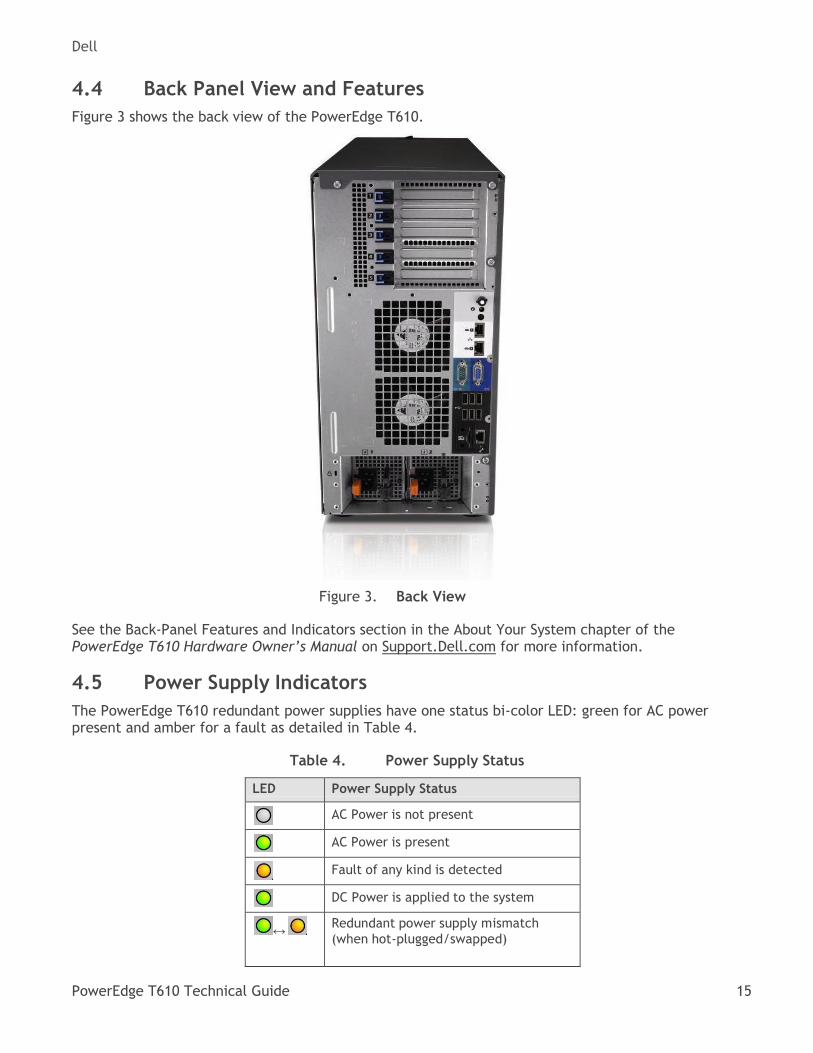
4.4 Back Panel View and Features
Figure 3 shows the back view of the PowerEdge T610.
Back View Figure 3.
See the Back-Panel Features and Indicators section in the About Your System chapter of the PowerEdge T610 Hardware Owner’s Manual on Support.Dell.com for more information.
4.5 Power Supply Indicators
The PowerEdge T610 redundant power supplies have one status bi-color LED: green for AC power present and amber for a fault as detailed in Table 4.
Power Supply Status Table 4.
LED Power Supply Status
AC Power is not present
AC Power is present
Fault of any kind is detected
DC Power is applied to the system
↔ Redundant power supply mismatch
(when hot-plugged/swapped)
Dell
PowerEdge T610 Technical Guide 16
See the Power Indicator Codes section in the About Your System chapter of the PowerEdge T610 Hardware Owner’s Manual on Support.Dell.com for more information.
4.6 NIC Indicators
See the NIC Indicator Codes section in the About Your System chapter of the PowerEdge T610 Hardware Owner’s Manual on Support.Dell.com for more information.
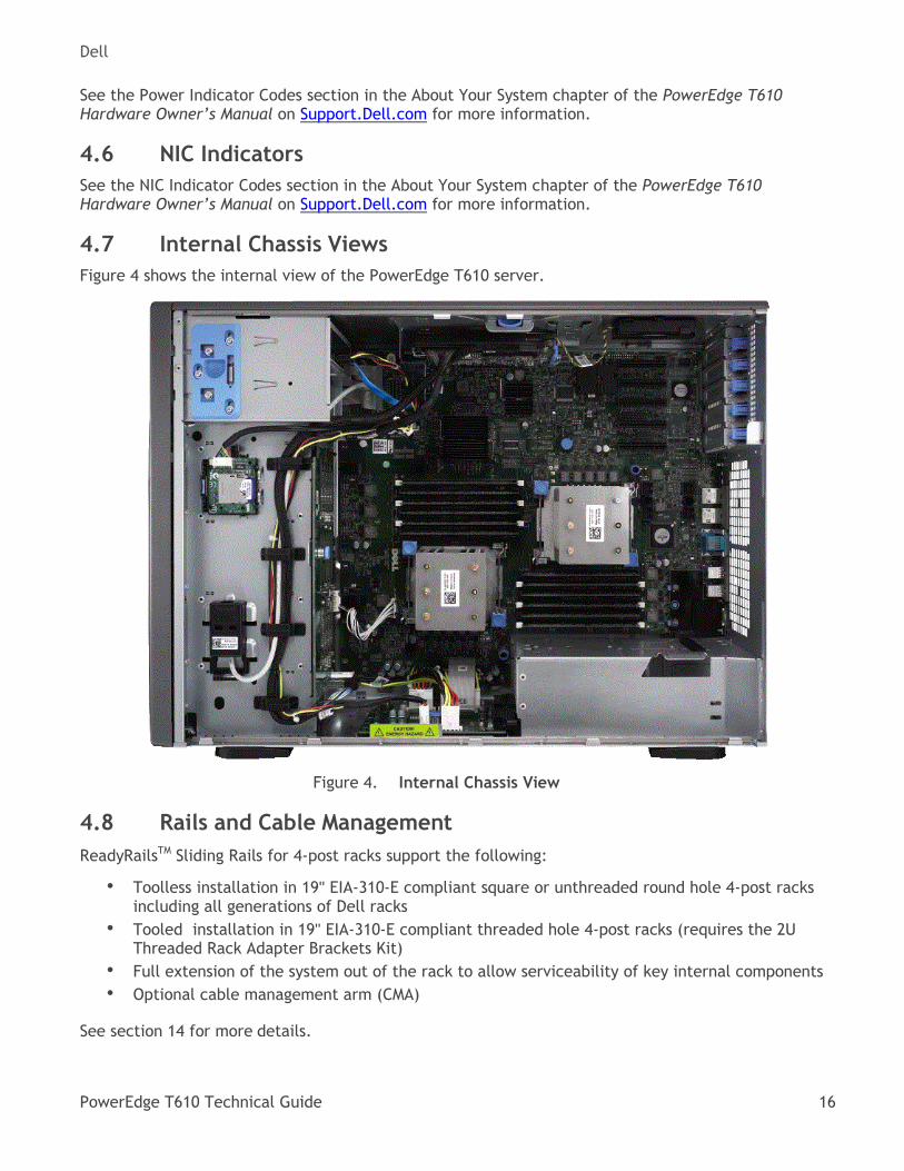
4.7 Internal Chassis Views
Figure 4 shows the internal view of the PowerEdge T610 server.
Internal Chassis View Figure 4.
4.8 Rails and Cable Management
ReadyRailsTM Sliding Rails for 4-post racks support the following:
• Toolless installation in 19" EIA-310-E compliant square or unthreaded round hole 4-post racks including all generations of Dell racks
• Tooled installation in 19" EIA-310-E compliant threaded hole 4-post racks (requires the 2U Threaded Rack Adapter Brackets Kit)
• Full extension of the system out of the rack to allow serviceability of key internal components
• Optional cable management arm (CMA)
See section 14 for more details.
Dell
PowerEdge T610 Technical Guide 17
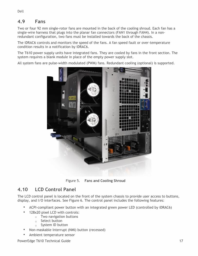
4.9 Fans
Two or four 92 mm single-rotor fans are mounted in the back of the cooling shroud. Each fan has a single-wire harness that plugs into the planar fan connectors (FAN1 through FAN4). In a non- redundant configuration, two fans must be installed towards the back of the chassis.
The iDRAC6 controls and monitors the speed of the fans. A fan speed fault or over-temperature condition results in a notification by iDRAC6.
The T610 power supply units have integrated fans. They are cooled by fans in the front section. The system requires a blank module in place of the empty power supply slot.
All system fans are pulse-width modulated (PWM) fans. Redundant cooling (optional) is supported.
Fans and Cooling Shroud Figure 5.
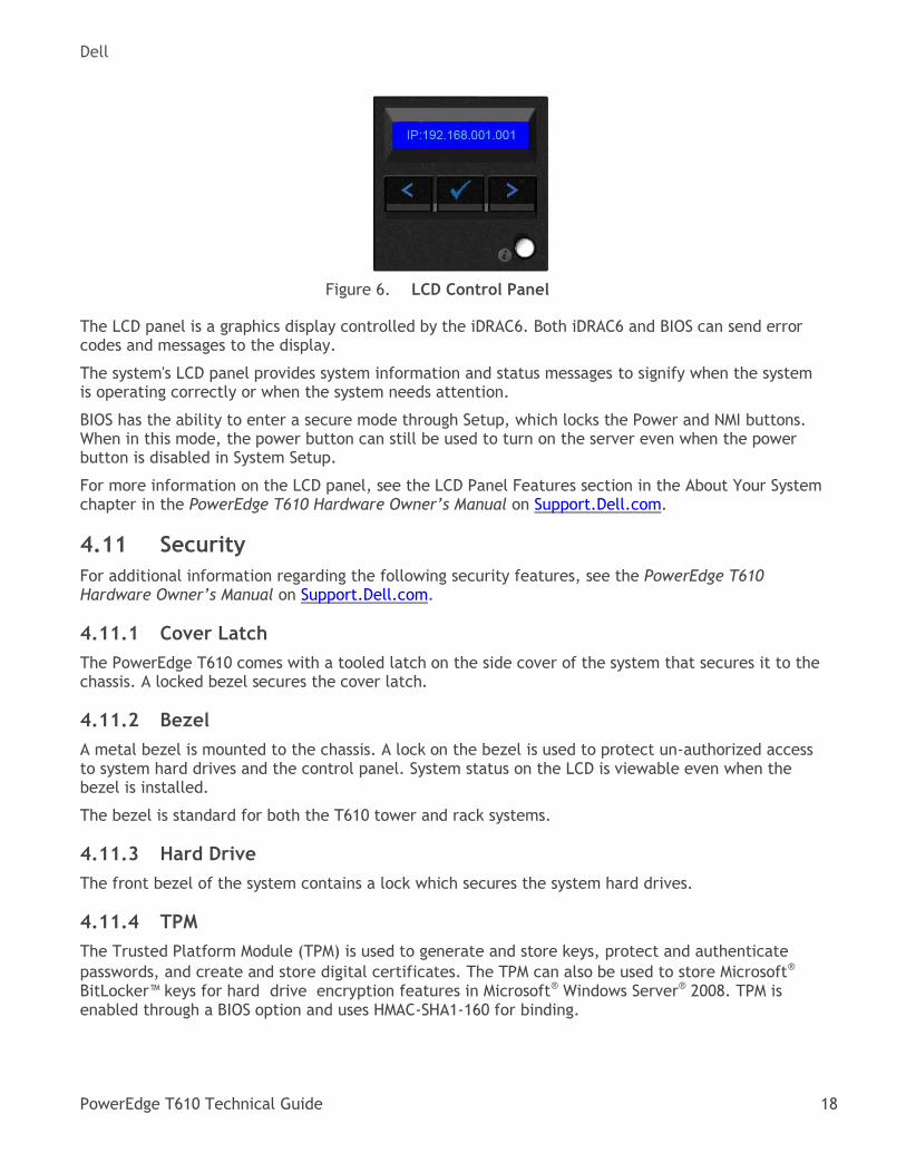
4.10 LCD Control Panel
The LCD control panel is located on the front of the system chassis to provide user access to buttons, display, and I/O interfaces. See Figure 6. The control panel includes the following features:
• ACPI-compliant power button with an integrated green power LED (controlled by iDRAC6)
• 128x20 pixel LCD with controls: o Two navigation buttons
o Select button o System ID button
• Non-maskable Interrupt (NMI) button (recessed)
• Ambient temperature sensor
Dell
PowerEdge T610 Technical Guide 18
LCD Control Panel Figure 6.
The LCD panel is a graphics display controlled by the iDRAC6. Both iDRAC6 and BIOS can send error codes and messages to the display.
The system's LCD panel provides system information and status messages to signify when the system is operating correctly or when the system needs attention.
BIOS has the ability to enter a secure mode through Setup, which locks the Power and NMI buttons. When in this mode, the power button can still be used to turn on the server even when the power button is disabled in System Setup.
For more information on the LCD panel, see the LCD Panel Features section in the About Your System chapter in the PowerEdge T610 Hardware Owner’s Manual on Support.Dell.com.
4.11 Security
For additional information regarding the following security features, see the PowerEdge T610 Hardware Owner’s Manual on Support.Dell.com.
4.11.1 Cover Latch
The PowerEdge T610 comes with a tooled latch on the side cover of the system that secures it to the chassis. A locked bezel secures the cover latch.
4.11.2 Bezel
A metal bezel is mounted to the chassis. A lock on the bezel is used to protect un-authorized access to system hard drives and the control panel. System status on the LCD is viewable even when the bezel is installed.
The bezel is standard for both the T610 tower and rack systems.
4.11.3 Hard Drive
The front bezel of the system contains a lock which secures the system hard drives.
4.11.4 TPM
The Trusted Platform Module (TPM) is used to generate and store keys, protect and authenticate
passwords, and create and store digital certificates. The TPM can also be used to store Microsoft®
BitLocker™ keys for hard drive encryption features in Microsoft® Windows Server® 2008. TPM is enabled through a BIOS option and uses HMAC-SHA1-160 for binding.
Dell
PowerEdge T610 Technical Guide 19
4.11.5 Power Off Security
The control panel is designed so the power switch cannot be accidentally activated. The lock on the bezel secures the switch behind the bezel. In addition, there is a setting in the CMOS setup that disables the power button function.
4.11.6 Intrusion Alert
A switch mounted on the cooling shroud is used to detect chassis intrusion. When the cover is opened, the switch circuit closes to indicate intrusion to the iDRAC6. When enabled, the software can provide notification to the customer that the cover has been opened.
4.11.7 Secure Mode
BIOS has the ability to enter a secure boot mode through Setup. This mode includes the option to lock out the power and NMI switches on the control panel or set up a system password.
4.12 USB Peripherals
The port on the control panel is for an optional USB key and is located inside the chassis. Some possible applications of the USB key are listed as follows:
• User custom boot and pre-boot OS for ease of deployment or diskless environments
• USB license keys for software applications like eToken™ or Sentinel Hardware Keys
• Storage of custom logs or scratch pads for portable user defined information (not hot- swappable)
4.13 Battery
A replaceable coin cell CR2032 3V battery is mounted on the planar to provide backup power for the Real-Time Clock and CMOS RAM on the ICH chip.
4.14 Field Replaceable Units (FRU)
The planar contains a serial EEPROM to store FRU information including Dell part number, part revision level, and serial number. The backplane storage enclosure processor (SEP) and the power supply microcontroller are also used to store FRU data.
4.15 User Accessible Jumpers, Sockets, and Connectors
See the Jumpers and Connectors chapter in the PowerEdge T610 Hardware Owner’s Manual on Support.Dell.com.
Dell
PowerEdge T610 Technical Guide 20
5 Power, Thermal, and Acoustic
5.1 Power Efficiencies
One of the main features of the Dell 11th generation servers is enhanced power efficiency. The T610 achieves higher power efficiency by implementing the following features:
• User-selectable power cap (subsystems throttle to maintain the specified power cap)
• Improved power budgeting
• Larger heat-sinks for processors and IOH
• Accurate inlet temperature
• Power-supply and voltage-regulator (VR) efficiency improvements
• Use of switching regulators instead of linear regulators
• Closed-loop thermal throttling
• Increased rear venting and 3D venting
• Pulse-width modulated (PWM) fans with an increased number of fan zones and configuration- dependent fan speeds
• Use of DDR3 memory (lower voltage compared to DDR2, UDIMM)
• Processor VR dynamic phase shedding
• Memory VR static phase shedding
• Random time interval for system start
• Ability for an entire rack to power on without exceeding the available power
• BIOS Power/Performance options page
• BIOS-based CPU P-state manager (power management in a virtualized environment)
• Active Power Controller (BIOS-based CPU P-state manager)
• Ability to power down or throttle memory
• Option to disable a processor core
• Ability to turn off embedded NICs or PCIe lanes when not being used
• Option to run PCIe at Gen1 speeds instead of Gen2
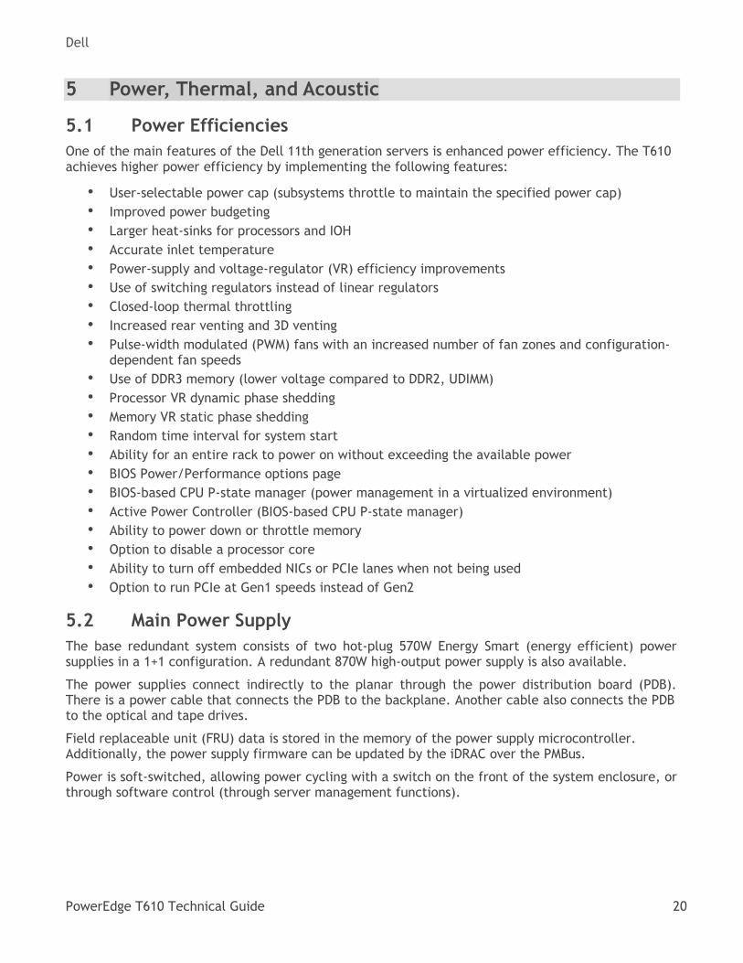
5.2 Main Power Supply
The base redundant system consists of two hot-plug 570W Energy Smart (energy efficient) power supplies in a 1+1 configuration. A redundant 870W high-output power supply is also available.
The power supplies connect indirectly to the planar through the power distribution board (PDB). There is a power cable that connects the PDB to the backplane. Another cable also connects the PDB to the optical and tape drives.
Field replaceable unit (FRU) data is stored in the memory of the power supply microcontroller. Additionally, the power supply firmware can be updated by the iDRAC over the PMBus.
Power is soft-switched, allowing power cycling with a switch on the front of the system enclosure, or through software control (through server management functions).
Dell
PowerEdge T610 Technical Guide 21
Power Supplies Figure 7.
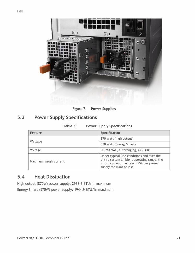
5.3 Power Supply Specifications
Power Supply Specifications Table 5.
Feature Specification
Wattage
870 Watt (high output)
570 Watt (Energy Smart)
Voltage 90-264 VAC, autoranging, 47-63Hz
Maximum inrush current
Under typical line conditions and over the entire system ambient operating range, the inrush current may reach 55A per power supply for 10ms or less.
5.4 Heat Dissipation
High output (870W) power supply: 2968.6 BTU/hr maximum
Energy Smart (570W) power supply: 1944.9 BTU/hr maximum
Dell
PowerEdge T610 Technical Guide 22
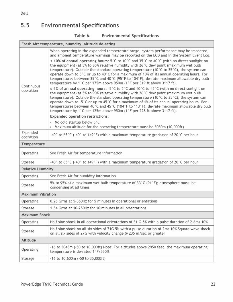
5.5 Environmental Specifications
Environmental Specifications Table 6.
Fresh Air: temperature, humidity, altitude de-rating
Continuous operation
When operating in the expanded temperature range, system performance may be impacted, and ambient temperature warnings may be reported on the LCD and in the System Event Log.
≤ 10% of annual operating hours: 5°C to 10°C and 35°C to 40°C (with no direct sunlight on the equipment) at 5% to 85% relative humidity with 26°C dew point (maximum wet bulb temperature). Outside the standard operating temperature (10°C to 35°C), the system can operate down to 5°C or up to 40°C for a maximum of 10% of its annual operating hours. For temperatures between 35°C and 40°C (95°F to 104°F), de-rate maximum allowable dry bulb temperature by 1°C per 175m above 950m (1°F per 319 ft above 3117 ft).
≤ 1% of annual operating hours: –5°C to 5°C and 40°C to 45°C (with no direct sunlight on the equipment) at 5% to 90% relative humidity with 26°C dew point (maximum wet bulb temperature). Outside the standard operating temperature (10°C to 35°C), the system can operate down to –5°C or up to 45°C for a maximum of 1% of its annual operating hours. For temperatures between 40°C and 45°C (104°F to 113°F), de-rate maximum allowable dry bulb temperature by 1°C per 125m above 950m (1°F per 228 ft above 3117 ft).
Expanded operation restrictions:
No cold startup below 5°C
Maximum altitude for the operating temperature must be 3050m (10,000ft)
Expanded operation
-40° to 65°C (-40° to 149°F) with a maximum temperature gradation of 20°C per hour
Temperature
Operating See Fresh Air for temperature information
Storage -40° to 65°C (-40° to 149°F) with a maximum temperature gradation of 20°C per hour
Relative Humidity
Operating See Fresh Air for humidity information
Storage 5% to 95% at a maximum wet bulb temperature of 33°C (91°F); atmosphere must be condensing at all times
Maximum Vibration
Operating 0.26 Grms at 5–350Hz for 5 minutes in operational orientations
Storage 1.54 Grms at 10–250Hz for 10 minutes in all orientations
Maximum Shock
Operating Half sine shock in all operational orientations of 31 G 5% with a pulse duration of 2.6ms 10%
Storage Half sine shock on all six sides of 71G 5% with a pulse duration of 2ms 10% Square wave shock on all six sides of 27G with velocity change @ 235 in/sec or greater
Altitude
Operating -16 to 3048m (-50 to 10,000ft) Note: For altitudes above 2950 feet, the maximum operating temperature is de-rated 1°F/550ft
Storage -16 to 10,600m (-50 to 35,000ft)
Dell
PowerEdge T610 Technical Guide 23
Airborne contaminant level
Class G1 or lower as defined by ISA-S71.04-1985 (G1 maximum corrosive contaminant levels measured at ≤ 50% relative humidity)
For additional information about environmental measurements for specific system configurations, see Dell.com/environmental_datasheets.
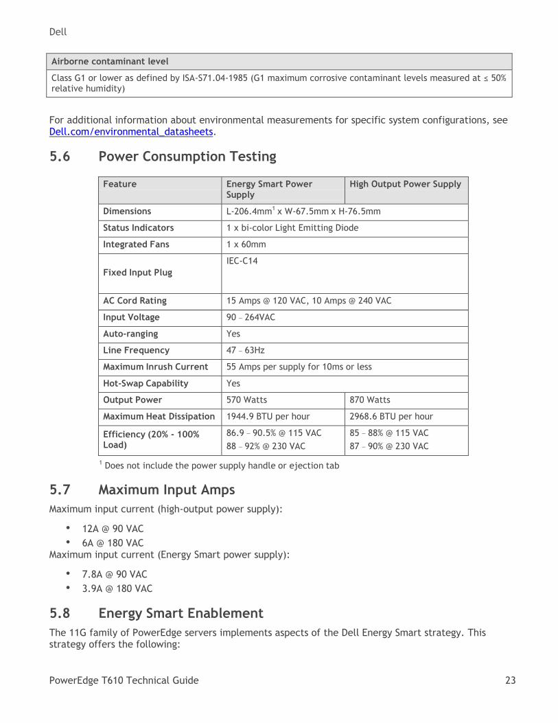
5.6 Power Consumption Testing
Feature Energy Smart Power Supply
High Output Power Supply
Dimensions L-206.4mm1 x W-67.5mm x H-76.5mm
Status Indicators 1 x bi-color Light Emitting Diode
Integrated Fans 1 x 60mm
Fixed Input Plug
IEC-C14
AC Cord Rating 15 Amps @ 120 VAC, 10 Amps @ 240 VAC
Input Voltage 90 – 264VAC
Auto-ranging Yes
Line Frequency 47 – 63Hz
Maximum Inrush Current 55 Amps per supply for 10ms or less
Hot-Swap Capability Yes
Output Power 570 Watts 870 Watts
Maximum Heat Dissipation 1944.9 BTU per hour 2968.6 BTU per hour
Efficiency (20% - 100% Load)
86.9 – 90.5% @ 115 VAC
88 – 92% @ 230 VAC
85 – 88% @ 115 VAC
87 – 90% @ 230 VAC
1 Does not include the power supply handle or ejection tab
5.7 Maximum Input Amps
Maximum input current (high-output power supply):
• 12A @ 90 VAC
• 6A @ 180 VAC Maximum input current (Energy Smart power supply):
• 7.8A @ 90 VAC
• 3.9A @ 180 VAC
5.8 Energy Smart Enablement
The 11G family of PowerEdge servers implements aspects of the Dell Energy Smart strategy. This strategy offers the following:
Dell
PowerEdge T610 Technical Guide 24
• Energy Smart components on a portfolio level, such as high-capacity and Energy Smart power supplies
• Systems with either a lowest power footprint configuration or a best performance per watt configuration
• Energy Smart components (such as DIMMs or hard drives) selected without cherry picking or screening individual manufacturer’s components based on energy consumption
5.9 ENERGY STAR Compliance
ENERGY STAR® qualified configurations can be accessed on the ENERGY STAR Compliance results webpage on Dell.com.
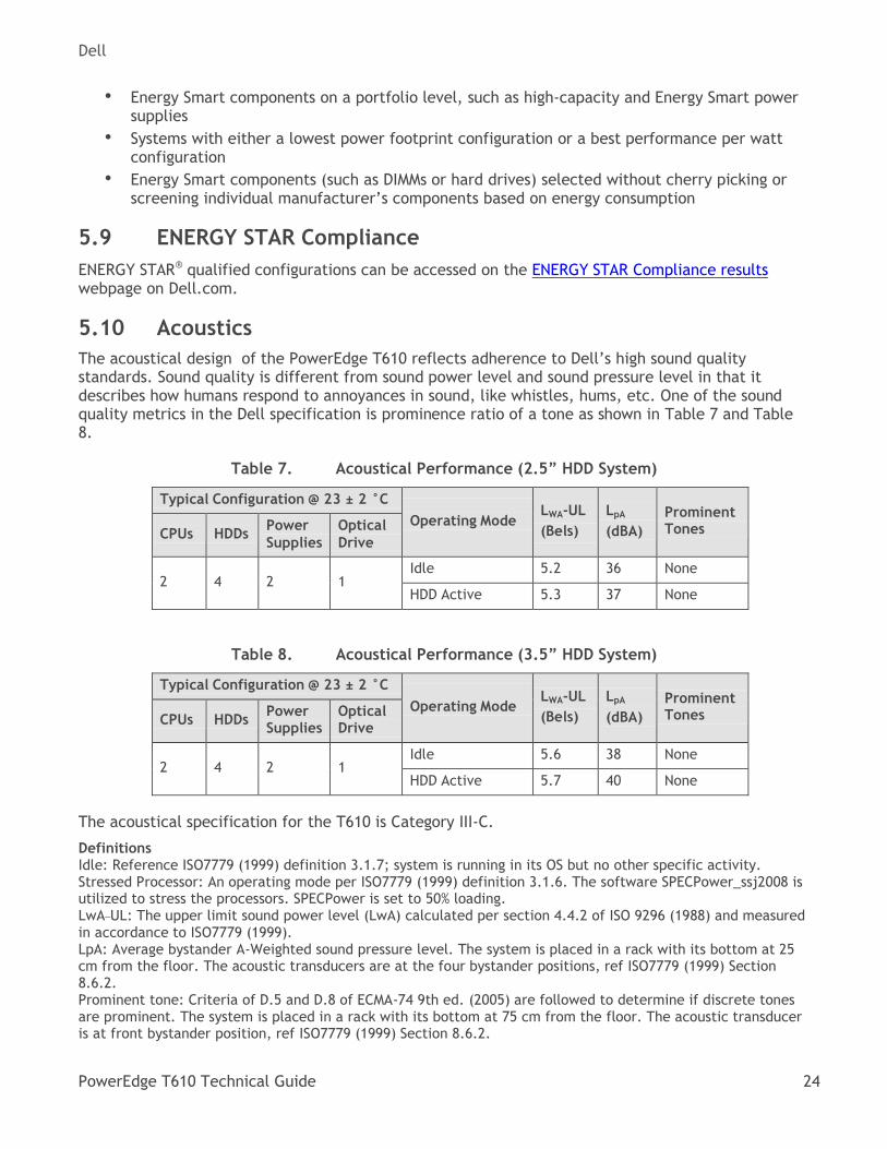
5.10 Acoustics
The acoustical design of the PowerEdge T610 reflects adherence to Dell’s high sound quality standards. Sound quality is different from sound power level and sound pressure level in that it describes how humans respond to annoyances in sound, like whistles, hums, etc. One of the sound quality metrics in the Dell specification is prominence ratio of a tone as shown in Table 7 and Table 8.
Acoustical Performance (2.5” HDD System) Table 7.
Typical Configuration @ 23 ± 2 °C
Operating Mode
LWA-UL
(Bels)
LpA
(dBA)
Prominent Tones
CPUs
HDDs Power
Supplies
Optical
Drive
2
4
2
1
Idle 5.2 36 None
HDD Active 5.3 37 None
Acoustical Performance (3.5” HDD System) Table 8.
Typical Configuration @ 23 ± 2 °C
Operating Mode
LWA-UL
(Bels)
LpA
(dBA)
Prominent Tones
CPUs
HDDs Power Supplies
Optical Drive
2
4
2
1
Idle 5.6 38 None
HDD Active 5.7 40 None
The acoustical specification for the T610 is Category III-C.
Definitions Idle: Reference ISO7779 (1999) definition 3.1.7; system is running in its OS but no other specific activity. Stressed Processor: An operating mode per ISO7779 (1999) definition 3.1.6. The software SPECPower_ssj2008 is utilized to stress the processors. SPECPower is set to 50% loading. LwA–UL: The upper limit sound power level (LwA) calculated per section 4.4.2 of ISO 9296 (1988) and measured in accordance to ISO7779 (1999). LpA: Average bystander A-Weighted sound pressure level. The system is placed in a rack with its bottom at 25 cm from the floor. The acoustic transducers are at the four bystander positions, ref ISO7779 (1999) Section 8.6.2. Prominent tone: Criteria of D.5 and D.8 of ECMA-74 9th ed. (2005) are followed to determine if discrete tones are prominent. The system is placed in a rack with its bottom at 75 cm from the floor. The acoustic transducer is at front bystander position, ref ISO7779 (1999) Section 8.6.2.
Dell
PowerEdge T610 Technical Guide 25
6 Processors
6.1 Overview
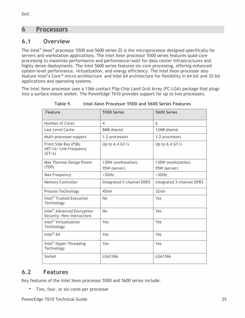
The Intel® Xeon® processor 5500 and 5600 series 2S is the microprocessor designed specifically for servers and workstation applications. The Intel Xeon processor 5500 series features quad-core processing to maximize performance and performance/watt for data center infrastructures and highly dense deployments. The Intel 5600 series features six-core processing, offering enhanced system-level performance, virtualization, and energy efficiency. The Intel Xeon processor also feature Intel’s Core™ micro-architecture and Intel 64 architecture for flexibility in 64-bit and 32-bit applications and operating systems.
The Intel Xeon processor uses a 1366-contact Flip-Chip Land Grid Array (FC-LGA) package that plugs into a surface mount socket. The PowerEdge T610 provides support for up to two processors.
Intel Xeon Processor 5500 and 5600 Series Features Table 9.
Feature 5500 Series 5600 Series
Number of Cores 4 6
Last Level Cache 8MB shared 12MB shared
Multi-processor support 1–2 processors 1-2 processors
Front Side Bus (FSB) (MT/s)/ Link Frequency (GT/s)
Up to 6.4 GT/s Up to 6.4 GT/s
Max Thermal Design Power (TDP)
130W (workstation)
95W (server)
130W (workstation)
95W (server)
Max Frequency >3GHz >3GHz
Memory Controller Integrated 3-channel DDR3 Integrated 3-channel DDR3
Process Technology 45nm 32nm
Intel® Trusted Execution Technology
No Yes
Intel® Advanced Encryption Security- New Instructions
No Yes
Intel® Virtualization Technology
Yes Yes
Intel® 64 Yes Yes
Intel® Hyper-Threading Technology
Yes Yes
Socket LGA1366 LGA1366
6.2 Features
Key features of the Intel Xeon processor 5500 and 5600 series include:
• Two, four, or six cores per processor
Dell
PowerEdge T610 Technical Guide 26
• Two point-to-point QuickPath Interconnect links at 6.4 GT/s
• 1366-pin FC-LGA package
• 32 nm and 45 nm process technology
• No termination required for non-populated processors (must populate CPU socket 1 first)
• Integrated QuickPath DDR3 memory controller 64-byte cache line size RISC/CISC hybrid architecture
• Compatible with existing x86 code base
• Intel MMX™ support—Execute Disable Bit Intel Wide Dynamic Execution
• Ability to executes up to four instructions per clock cycle
• Simultaneous Multi-Threading (SMT) capability
• Support for CPU Turbo Mode (on certain processors)—increases processor frequency if operating below thermal, power, and current limits for streaming SIMD (Single Instruction, Multiple Data) Extensions 2, 3, and 4
• Intel 64 Technology Intel VT-x and VT-d Technology for virtualization support Enhanced Intel
• SpeedStep® Technology
• Demand-based switching for active processor power management as well as support for ACPI P-States, C-States and T-States
• Support for DDR3L, 1.35V DIMMs for even lower system power (5600 series)
• Support for memory sparing (5600 series)
• AES-NI (hardware encryption assist) for more efficient encryption for uses such as online transactions SSL (5600 series)
• Intel TXT (Trusted Execution Technology) provides hardware assisted protection against emerging software attacks (5600 series)
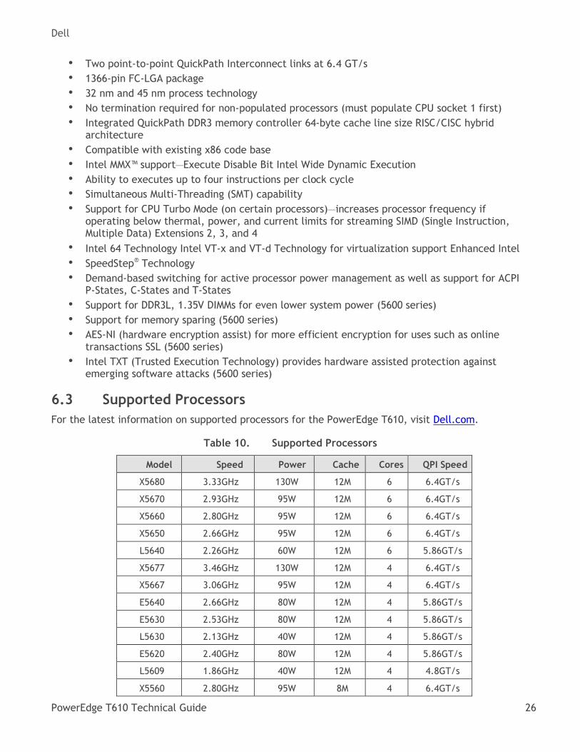
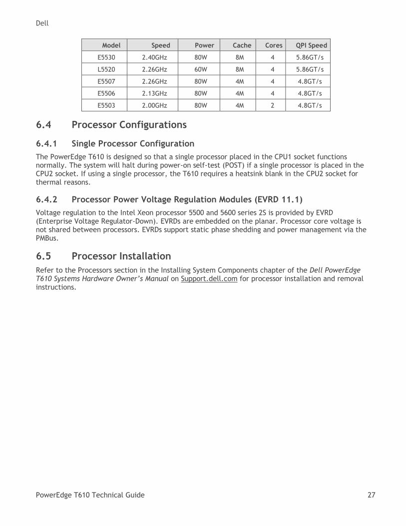
6.3 Supported Processors
For the latest information on supported processors for the PowerEdge T610, visit Dell.com.
Supported Processors Table 10.
Model Speed Power Cache Cores QPI Speed
X5680 3.33GHz 130W 12M 6 6.4GT/s
X5670 2.93GHz 95W 12M 6 6.4GT/s
X5660 2.80GHz 95W 12M 6 6.4GT/s
X5650 2.66GHz 95W 12M 6 6.4GT/s
L5640 2.26GHz 60W 12M 6 5.86GT/s
X5677 3.46GHz 130W 12M 4 6.4GT/s
X5667 3.06GHz 95W 12M 4 6.4GT/s
E5640 2.66GHz 80W 12M 4 5.86GT/s
E5630 2.53GHz 80W 12M 4 5.86GT/s
L5630 2.13GHz 40W 12M 4 5.86GT/s
E5620 2.40GHz 80W 12M 4 5.86GT/s
L5609 1.86GHz 40W 12M 4 4.8GT/s
X5560 2.80GHz 95W 8M 4 6.4GT/s
Dell
PowerEdge T610 Technical Guide 27
Model Speed Power Cache Cores QPI Speed
E5530 2.40GHz 80W 8M 4 5.86GT/s
L5520 2.26GHz 60W 8M 4 5.86GT/s
E5507 2.26GHz 80W 4M 4 4.8GT/s
E5506 2.13GHz 80W 4M 4 4.8GT/s
E5503 2.00GHz 80W 4M 2 4.8GT/s
6.4 Processor Configurations
6.4.1 Single Processor Configuration
The PowerEdge T610 is designed so that a single processor placed in the CPU1 socket functions normally. The system will halt during power-on self-test (POST) if a single processor is placed in the CPU2 socket. If using a single processor, the T610 requires a heatsink blank in the CPU2 socket for thermal reasons.
6.4.2 Processor Power Voltage Regulation Modules (EVRD 11.1)
Voltage regulation to the Intel Xeon processor 5500 and 5600 series 2S is provided by EVRD (Enterprise Voltage Regulator-Down). EVRDs are embedded on the planar. Processor core voltage is not shared between processors. EVRDs support static phase shedding and power management via the PMBus.
6.5 Processor Installation
Refer to the Processors section in the Installing System Components chapter of the Dell PowerEdge T610 Systems Hardware Owner’s Manual on Support.dell.com for processor installation and removal instructions.
Dell
PowerEdge T610 Technical Guide 28
7 Memory
7.1 Overview
The PowerEdge T610 utilizes DDR3 memory, providing a high performance, high-speed memory interface capable of low latency response and high throughput. The T610 supports Registered ECC DDR3 DIMMs (RDIMM) or Unbuffered ECC DDR3 DIMMs (UDIMM).
Key features of the T610 memory system include:
• Registered (RDIMM) and Unbuffered (UDIMM) DDR3 technology
• Each channel carries 64 data and eight ECC bits
• Support for up to 192 GB of RDIMM memory (twelve 16 GB RDIMMs)
• Support for up to 24 GB of UDIMM memory (twelve 2 GB UDIMMs)
• Support for 1066/1333MT/s single and dual rank DIMMs
• Support for 1066MT/s quad rank DIMMs
• Support for 1.35V low voltage (LV) DIMMs with 5600 series processors
• Single DIMM configuration with DIMM at socket DIMM A1
• Support ODT (On Die Termination)
• Clock gating (CKE) to conserve power when DIMMs are not accessed
• DIMMs will enter a low power self-refresh mode
• I2C access to SPD EEPROM and thermal sensors
• Single Bit Error Correction
• SDDC (Single Device Data Correction, x4 or x8 devices)
• Multi Bit Error Detection
• Support for Closed Loop Thermal Management on RDIMMs and UDIMMs
• Support for Advanced ECC mode
• Support for Memory Optimized mode
• Support for Memory Mirroring
• Support for Memory Sparing with 5600 series processors
7.2 DIMMs Supported
The DDR3 memory interface consists of three channels with up to two RDIMMs or UDIMMs per channel for single- or dual-rank and up to two RDIMMs per channel for quad-rank. The interface uses 2GB, 4GB, 8GB, or 16GB RDIMMs. Also supported are 1GB or 2GB UDIMMs.
7.2.1 Memory Modes
The memory mode is dependent on how the memory is populated in the system, according to the following configurations:
• Three channels per processor populated identically o Typically, the system will be set to run in Memory Optimized (Independent Channel)
• mode in this configuration. o This mode offers the most DIMM population flexibility and system memory capacity,
but offers the least number of RAS (reliability, availability, service) features.
o All three channels must be populated identically.
• The first two channels per processor populated identically with the third channel unused
Dell
PowerEdge T610 Technical Guide 29
o Typically, two channels operate in Advanced ECC (Lockstep) mode with each other by having the cache line split across both channels.
o This mode provides improved RAS features (SDDC support for x8-based memory). o For memory mirroring, two channels operate as mirrors of each other (writes go to
both channels and reads alternate between the two channels). o For Memory Mirroring, two channels operate as mirrors of each other—writes go to
both channels and reads alternate between the two channels.
• One channel per processor populated o This is a simple Memory Optimized mode.
o Mirroring is not supported.
7.2.2 DIMM Population Rules
The following DIMM population rules apply:
• If DIMMs of different speeds are mixed, all channels will operate at the fastest common frequency. RDIMMs and UDIMMs cannot be mixed.
• If memory mirroring is enabled, identical DIMMs must be installed in the same slots across both channels.
• The third channel of each processor is unavailable for memory mirroring.
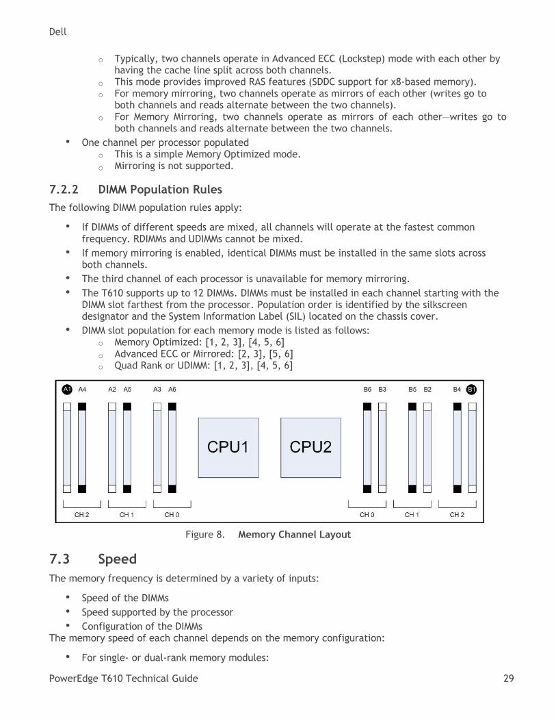
• The T610 supports up to 12 DIMMs. DIMMs must be installed in each channel starting with the DIMM slot farthest from the processor. Population order is identified by the silkscreen designator and the System Information Label (SIL) located on the chassis cover.
• DIMM slot population for each memory mode is listed as follows: o Memory Optimized: [1, 2, 3], [4, 5, 6]
o Advanced ECC or Mirrored: [2, 3], [5, 6] o Quad Rank or UDIMM: [1, 2, 3], [4, 5, 6]
Memory Channel Layout Figure 8.
7.3 Speed
The memory frequency is determined by a variety of inputs:
• Speed of the DIMMs
• Speed supported by the processor
• Configuration of the DIMMs The memory speed of each channel depends on the memory configuration:
• For single- or dual-rank memory modules:
Dell
PowerEdge T610 Technical Guide 30
o One memory module per channel supports up to 1333MT/s
o Two memory modules per channel supports up to 1066MT/s
• For quad-rank memory modules:
o One memory module per channel supports up to 1066MT/s o Two memory modules per channel are limited to 800MT/s, regardless of memory
module speed
If memory modules with different speeds are installed, they will operate at the speed of the slowest installed memory module(s).
For quad-rank DIMMs mixed with single- or dual-rank DIMMs, the quad-rank DIMM must be installed in the slot with the white ejection tabs (the first DIMM slot in each channel). There is no requirement for the order of single- and dual-rank DIMMs.
7.4 DIMM Slots
The PowerEdge T610 has 12 DIMM slots for memory. It does not have any riser cards for DIMM population.
The first DIMM slot in each channel is color-coded with white ejection tabs for ease of installation. The DIMM sockets are placed 450 mils (11.43 mm) apart, center-to-center to provide enough space for sufficient airflow to cool stacked DIMMs.
7.5 Low Voltage DIMMs
With the introduction of the Intel® Xeon® processor 5600 series, low voltage (LV) DIMMs have been added for selected memory configurations for the PowerEdge T610. Only this processor series supports operating DIMMs at the lower voltage (1.35V, also referred to as DDR3L). The Intel Xeon 5500 processor series does not support low voltage operation. However, they can be operated at 1.5V. Therefore, DDR3L DIMMs can be used in systems with either processor series, and the platform will automatically choose the appropriate operating voltage based on the processor populated.
LV DIMMs operate at 1.35V, creating power savings vs. standard memory which operates at 1.5V. In order to achieve power savings, all DIMMs in the system must be of the LV type. If the system detects a mixture of standard and LV DIMMs, the BIOS will operate all memory at 1.5V. When operating at the lower voltage, additional frequency and population restrictions can take effect. For example, 3 DIMMs per channel operation is not supported at low voltage.
The DDR3L standard is completely backward compatible at standard voltage. DDR3L DIMMs can operate at 1.5V without any limitations beyond standard voltage DDR3 DIMMs. As part of the addition of LV DIMMs, the platform has certain default behaviors. Whenever possible, if there is no performance degradation, the platform will default to 1.35V operation when using DDR3L DIMMs. In certain cases, where a configuration is populated that cannot support 1.35V or a performance degradation would result, the platform defaults to 1.5V operation. There are also options to override default voltage within allowed limits.
7.6 Mirroring
The T610 system supports memory mirroring if identical memory modules are installed in the two channels closest to the processor (memory not installed in the farthest channel). Mirroring must be enabled in the System Setup program. In a mirrored configuration, the total available system memory is one-half of the total installed physical memory.
Dell
PowerEdge T610 Technical Guide 31
7.7 Sparing
Systems with the Intel Xeon processor 5600 series support memory sparing. Sparing requires identical memory installed in all three channels. One of the three channels is considered the Spare Channel, and two-thirds of the total installed memory is usable and is the amount reported during POST and in BIOS setup.
7.8 Memory Scrubbing
The T610 memory interface supports memory demand and patrol scrubbing, single-bit correction and multi-bit error detection. Correction of a x4 or x8 device failure is also possible with (SDDC) in the Advanced ECC mode. Additionally, correction of a x4 device failure is possible in the Memory Optimized mode.
7.9 Advanced ECC (Lockstep) Mode
In this configuration, the two channels closest to the processor are combined to form one 128-bit channel. This mode supports SDDC for both x4- and x8-based memory modules. Memory modules must be identical in size, speed and technology in corresponding slots.
7.10 Optimizer (Independent Channel) Mode
In Optimizer (Independent Channel) mode, all three channels are populated with identical memory modules. This mode permits a larger total memory capacity but does not support SDDC with x8-based memory modules.
A minimal single-channel configuration of 1 GB memory modules per processor is also supported in this mode.
7.11 Supported Configurations
See the System Memory section in the Installing System Components chapter in the Dell PowerEdge T610 Systems Hardware Owner's Manual on Support.dell.com.
Dell
PowerEdge T610 Technical Guide 32
8 Chipset
8.1 Overview
The PowerEdge T610 planar incorporates the Intel® Xeon® 5520 processor series chipset for I/O and processor interfacing. This chipset is designed to support the Intel Xeon 5500 and 5600 processor series family, QuickPath Interconnect, DDR3 memory technology, and PCI Express Generation 2. The chipset consists of the Intel 5520 chipset I/O Hub (IOH) and ICH9.
8.2 Intel I/O Hub (IOH)
The planar uses the Intel 5520 chipset IOH to provide a link between the Intel Xeon processor series 5500 and 5600 processor(s) and the I/O components. The main components of the IOH consist of two full-width QuickPath Interconnect links (one to each processor), 36 lanes of PCI Express Gen2, a x4 Direct Media Interface (DMI), and an integrated IOxAPIC.
8.3 IOH QuickPath Interconnect (QPI)
The QuickPath Architecture consists of serial point-to-point interconnects for the processors and the IOH. The T610 has a total of three QuickPath Interconnect (QPI) links—one link connecting the processors, and multiple links connecting both processors with the IOH. Each link consists of 20 lanes (full-width) in each direction with a link speed of 6.4 GT/s. An additional lane is reserved for a forwarded clock. Data is sent over the QPI links as packets.
The QuickPath Architecture implemented in the IOH and processors features four layers:
• Physical layer—Consists of the actual connection between components. Supports Polarity
• Inversion and Lane Reversal for optimizing component placement and routing.
• Link layer—Responsible for flow control and the reliable transmission of data.
• Routing layer—Responsible for the routing of QPI data packets.
• Protocol layer—Responsible for high-level protocol communications, including the implementation of a MESIF (Modify, Exclusive, Shared, Invalid, Forward) cache coherence protocol.
8.4 Intel Direct Media Interface (DMI)
The DMI connects the Intel 5520 chipset IOH with the Intel I/O Controller Hub (ICH). The DMI is equivalent to a x4 PCIe Gen1 link with a transfer rate of 1 GB/s in each direction.
8.5 PCI Express
PCI Express is a serial point-to-point interconnect for I/O devices. PCIe Generation 2 doubles the signaling bit rate of each lane from 2.5Gb/s to 5Gb/s. Each of the PCIe Gen2 ports are backwards- compatible with Gen1 transfer rates.
The IOH has two x2 PCIe Gen2 ports (1 GB/s) and eight x4 PCIe Gen2 ports (2GB/s). The x2 ports can be combined as a x4 link; however, this x4 link cannot be combined with any of the other x4 ports. Two neighboring x4 ports can be combined as a x8 link, and both resulting x8 links can combine to form a x16 link.
Dell
PowerEdge T610 Technical Guide 33
8.6 Intel I/O Controller Hub 9 (ICH9)
ICH9 is a highly integrated I/O controller, supporting the following functions:
• Six x1 PCIe Gen1 ports, with the capability of combining ports 1-4 as a x4 link (ports are unused on T610)
• PCI Bus 32-bit Interface Rev 2.3 running at 33MT/s
• Up to six Serial ATA (SATA) ports with transfer rates up to 300MB/s (T610 features two SATA port for optional internal optical drive or tape backup)
• Six UHCI and two EHCI (high-speed 2.0) USB host controllers, with up to twelve USB ports
• Eight external USB ports and two internal ports dedicated for Unmanaged Internal Persistent Storage (UIPS)
• Power management interface (ACPI 3.0b compliant)
• Platform Environmental Control Interface (PECI)
• Intel Dynamic Power Mode Manager
• I/O interrupt controller
• SMBus 2.0 controller
• Low Pin Count (LPC) interface to Super I/O, Trusted Platform Module (TPM), and SuperVU
• Serial Peripheral Interface (SPI) support for up to two devices (T610 BIOS is connected to the ICH9 using SPI)
Dell
PowerEdge T610 Technical Guide 34
9 BIOS
9.1 Overview
The PowerEdge T610 BIOS is based on the Dell BIOS core and supports the following features:
• Simultaneous Multi-Threading (SMT) support
• Processor Turbo Mode support
• PCI 2.3 compliant
• Plug and Play 1.0a compliant
• MP (Multiprocessor) 1.4 compliant
• Ability to boot from hard drive, optical drive, iSCSI drive, USB key, and SD card
• ACPI support
• Direct Media Interface (DMI) support
• PXE and WOL support for on-board NICs
• Memory mirroring support
• SETUP access through <F2> key at end of POST
• USB 2.0 (USB boot code is 1.1 compliant)
• F1/F2 error logging in CMOS
• Virtual KVM, CD, and floppy support
• Unified Extensible Firmware Interface (UEFI) 2.1 support
• Power management support including DBS, Power Inventory and multiple power profiles
• Intel TXT (5600 processor series)
• Intel AESNI (5600 processor series)
The T610 BIOS does not support the following:
• BIOS language localization
• BIOS recovery after bad flash (can be recovered from iDRAC6 Express)
9.2 Supported ACPI States
Advanced Configuration and Power Interface (ACPI) is a standard interface for enabling the operating system to direct configuration and power management.
The Intel Xeon processor 5500 and 5600 series supports the following C-States: C0, C1, C1E, C3, and C6. The T610 supports all of the available C-States.
9.3 I2C (Inter-Integrated Circuit)
I2C is a simple bi-directional two-wire bus for efficient inter-integrated circuit control. All I2C-bus compatible devices incorporate an on-chip interface which allows them to communicate directly with
each other via the I2C bus. This design concept solves the many interfacing problems encountered
when designing digital control circuits. These I2C devices perform communication functions between intelligent control devices (such as microcontrollers), general-purpose circuits (such as LCD drivers, remote I/O ports, memories) and application-oriented circuits.
Dell
PowerEdge T610 Technical Guide 35
The PowerEdge T610 BIOS accesses the I2C through the ICH9 (Intel I/O Controller Hub 9). There are
two multiplexers (MUX) on the ICH9 I2C bus.
• One MUX (U_ICH_SPD) controls the DIMM SPDs through four split segments
• The other MUX (U_ICH_MAIN) controls the clock buffers, TOE, and USB Hub through four split segments.
BIOS controls both the MUXes through the two select lines using GPIO pins. The clock chip, USB hub,
and the front panel EEPROM device addresses are located on the IOH I2C bus.
Dell
PowerEdge T610 Technical Guide 36
10 Embedded NICs/LAN on Motherboard (LOM)
The PowerEdge T610 has an embedded dual-port Gigabit Ethernet controller with TCP Offload Engine
(TOE) support. The embedded Broadcom® 5709C dual-port LAN controller is on the T610 planar as an independent Gigabit Ethernet interface device. The following information details the features of the LAN device:
• x4 PCI Express Gen2 capable interface (controller operated at Gen1 speed)
• Integrated MAC and PHY
• 3072x18 Byte context memory
• 64 KB receive buffer
• TOE (TCP Offload Engine)
• iSCSI controller (enabled through optional hardware key)
• RDMA controller (RNIC) (enabled through an optional hardware key)
• NC-SI (Network Controller-Sideband Interface) connection
• Wake-On-LAN (WOL)
• PXE 2.0 remote boot
• iSCSI boot
• IPv4 and IPv6 support
• Bare metal deployment support
Dell
PowerEdge T610 Technical Guide 37
11 PCI Slots
11.1 Overview
The PowerEdge T610 has five PCI Express expansion slots and one dedicated storage slot, which are detailed as follows:
• Two x8 PCIe Gen2 slots for full-height full-length cards connected to the IOH
• Three x4 PCIe Gen2 slots for full-height half-length cards connected to the IOH
• One x4 PCIe Gen1 slot for a dedicated storage controller card connected to the IOH
The system supports 25W maximum power for the first two PCIe cards and 15W for the third, fourth, and fifth PCIe cards. The lower-power support on the third, fourth, and fifth cards is due to system thermal limitations and not due to system power requirements.
The system does not support hot-plugging or hot-removal of PCI Express cards.
For more information on installing expansion cards and expansion-card priority, see the Expansion Cards and Expansion-Card Risers section in the Installing System Components chapter of the Dell PowerEdge T610 Systems Hardware Owner’s Manual on Support.Dell.com.
11.2 Quantities and Priorities
Refer to the Expansion Cards and Expansion-Card Risers section in the Installing System Components chapter of the Dell PowerEdge T610 Systems Hardware Owner’s Manual on Support.Dell.com.
11.3 PCI Card Dimensions
For information about PCIe slots and card dimensions, see the Expansion Cards and Expansion-Card Risers section in the Installing System Components chapter in the Dell PowerEdge T610 Systems Hardware Owner’s Manual on Support.Dell.com.
Dell
PowerEdge T610 Technical Guide 38
12 Storage
12.1 Overview
The PowerEdge T610 is available in two different hard-drive configurations:
• 8 x 2.5" hard drives
• 8 x 3.5" hard drives
Each configuration has a unique chassis and hard-drive backplane. Both chassis have eight hot-swap-capable Serial Attached SCSI (SAS) or Serial ATA (SATA) slots with two LED indicators per slot, two mini-SAS cable connectors for connecting the backplane to the integrated SAS 6/iR (PERC H200) or PERC 6/i (PERC H700), a 10-pin planar signal connector, and an 8-pin PDB power connector.
For SATA and SAS mixing, two SAS drives (in bay 0 and 1) are supported with the 2.5" or 3.5" backplane. In this configuration, one pair of drives will be SAS and the remaining six drives will be SATA.
12.2 Internal Hard Disk Drives
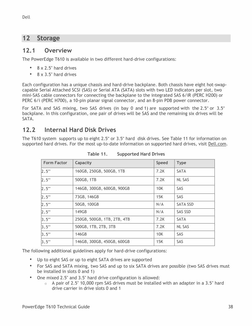
The T610 system supports up to eight 2.5" or 3.5" hard disk drives. See Table 11 for information on supported hard drives. For the most up-to-date information on supported hard drives, visit Dell.com.
Supported Hard Drives Table 11.
Form Factor Capacity Speed Type
2.5" 160GB, 250GB, 500GB, 1TB 7.2K SATA
2.5" 500GB, 1TB 7.2K NL SAS
2.5" 146GB, 300GB, 600GB, 900GB 10K SAS
2.5" 73GB, 146GB 15K SAS
2.5" 50GB, 100GB N/A SATA SSD
2.5" 149GB N/A SAS SSD
3.5" 250GB, 500GB, 1TB, 2TB, 4TB 7.2K SATA
3.5" 500GB, 1TB, 2TB, 3TB 7.2K NL SAS
3.5" 146GB 10K SAS
3.5" 146GB, 300GB, 450GB, 600GB 15K SAS
The following additional guidelines apply for hard-drive configurations:
• Up to eight SAS or up to eight SATA drives are supported
• For SAS and SATA mixing, two SAS and up to six SATA drives are possible (two SAS drives must be installed in slots 0 and 1)
• One mixed 2.5" and 3.5" hard drive configuration is allowed: o A pair of 2.5" 10,000 rpm SAS drives must be installed with an adapter in a 3.5" hard
drive carrier in drive slots 0 and 1
Dell
PowerEdge T610 Technical Guide 39
o The remaining hard drives must be 3.5" hard drives and must be either all SAS or all SATA
• Solid state drives (SSDs) require the PERC 6/i (PERC H700) integrated storage controller and cannot be mixed with any other type of hard drive
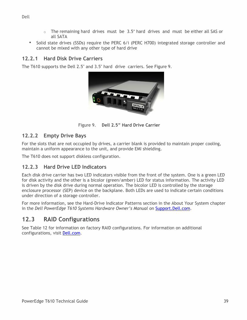
12.2.1 Hard Disk Drive Carriers
The T610 supports the Dell 2.5" and 3.5" hard drive carriers. See Figure 9.
Dell 2.5” Hard Drive Carrier Figure 9.
12.2.2 Empty Drive Bays
For the slots that are not occupied by drives, a carrier blank is provided to maintain proper cooling, maintain a uniform appearance to the unit, and provide EMI shielding.
The T610 does not support diskless configuration.
12.2.3 Hard Drive LED Indicators
Each disk drive carrier has two LED indicators visible from the front of the system. One is a green LED for disk activity and the other is a bicolor (green/amber) LED for status information. The activity LED is driven by the disk drive during normal operation. The bicolor LED is controlled by the storage enclosure processor (SEP) device on the backplane. Both LEDs are used to indicate certain conditions under direction of a storage controller.
For more information, see the Hard-Drive Indicator Patterns section in the About Your System chapter in the Dell PowerEdge T610 Systems Hardware Owner’s Manual on Support.Dell.com.
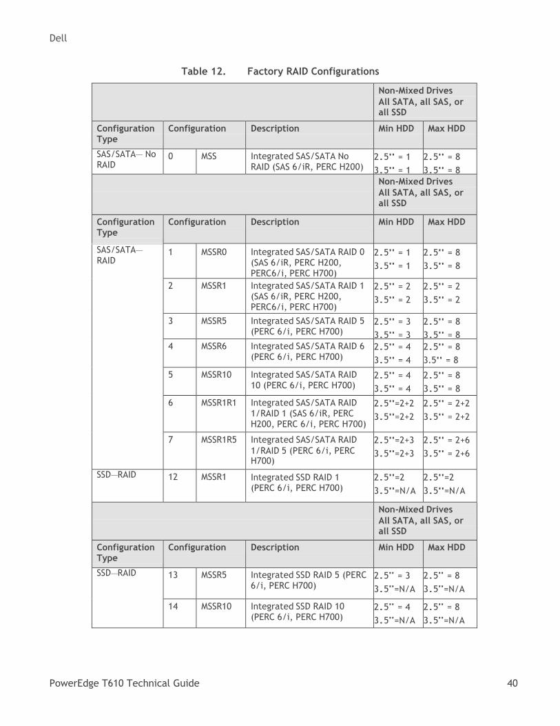
12.3 RAID Configurations
See Table 12 for information on factory RAID configurations. For information on additional configurations, visit Dell.com.
Dell
PowerEdge T610 Technical Guide 40
Factory RAID Configurations Table 12.
Non-Mixed Drives
All SATA, all SAS, or all SSD
Configuration Type
Configuration Description Min HDD Max HDD
SAS/SATA— No RAID
0 MSS Integrated SAS/SATA No RAID (SAS 6/iR, PERC H200)
2.5" = 1
3.5" = 1
2.5" = 8
3.5" = 8 Non-Mixed Drives
All SATA, all SAS, or all SSD
Configuration Type
Configuration Description Min HDD Max HDD
SAS/SATA—
RAID 1 MSSR0 Integrated SAS/SATA RAID 0
(SAS 6/iR, PERC H200, PERC6/i, PERC H700)
2.5" = 1
3.5" = 1
2.5" = 8
3.5" = 8
2 MSSR1 Integrated SAS/SATA RAID 1 (SAS 6/iR, PERC H200, PERC6/i, PERC H700)
2.5" = 2
3.5" = 2
2.5" = 2
3.5" = 2
3 MSSR5 Integrated SAS/SATA RAID 5 (PERC 6/i, PERC H700)
2.5" = 3
3.5" = 3
2.5" = 8
3.5" = 8
4 MSSR6 Integrated SAS/SATA RAID 6 (PERC 6/i, PERC H700)
2.5" = 4
3.5" = 4
2.5" = 8
3.5" = 8
5 MSSR10 Integrated SAS/SATA RAID 10 (PERC 6/i, PERC H700)
2.5" = 4
3.5" = 4
2.5" = 8
3.5" = 8
6 MSSR1R1 Integrated SAS/SATA RAID 1/RAID 1 (SAS 6/iR, PERC H200, PERC 6/i, PERC H700)
2.5"=2+2
3.5"=2+2
2.5" = 2+2
3.5" = 2+2
7 MSSR1R5 Integrated SAS/SATA RAID
1/RAID 5 (PERC 6/i, PERC H700)
2.5"=2+3
3.5"=2+3
2.5" = 2+6
3.5" = 2+6
SSD—RAID 12 MSSR1 Integrated SSD RAID 1 (PERC 6/i, PERC H700)
2.5"=2
3.5"=N/A
2.5"=2
3.5"=N/A
Non-Mixed Drives
All SATA, all SAS, or all SSD
Configuration Type
Configuration Description Min HDD Max HDD
SSD—RAID 13 MSSR5 Integrated SSD RAID 5 (PERC 6/i, PERC H700)
2.5" = 3
3.5"=N/A
2.5" = 8
3.5"=N/A
14 MSSR10 Integrated SSD RAID 10 (PERC 6/i, PERC H700)
2.5" = 4
3.5"=N/A
2.5" = 8
3.5"=N/A
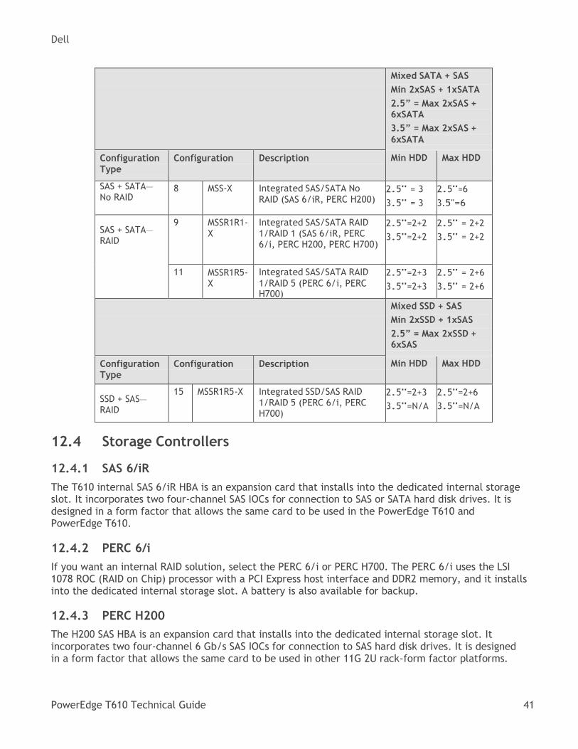
Dell
PowerEdge T610 Technical Guide 41
Mixed SATA + SAS
Min 2xSAS + 1xSATA
2.5” = Max 2xSAS + 6xSATA
3.5” = Max 2xSAS +
6xSATA
Configuration
Type
Configuration Description Min HDD Max HDD
SAS + SATA—
No RAID 8 MSS-X Integrated SAS/SATA No
RAID (SAS 6/iR, PERC H200) 2.5" = 3
3.5" = 3
2.5"=6
3.5"=6
SAS + SATA—
RAID
9 MSSR1R1- X
Integrated SAS/SATA RAID 1/RAID 1 (SAS 6/iR, PERC 6/i, PERC H200, PERC H700)
2.5"=2+2
3.5"=2+2
2.5" = 2+2
3.5" = 2+2
11 MSSR1R5- X
Integrated SAS/SATA RAID
1/RAID 5 (PERC 6/i, PERC H700)
2.5"=2+3
3.5"=2+3
2.5" = 2+6
3.5" = 2+6
Mixed SSD + SAS
Min 2xSSD + 1xSAS
2.5” = Max 2xSSD + 6xSAS
Configuration Type
Configuration Description Min HDD Max HDD
SSD + SAS—
RAID
15 MSSR1R5-X Integrated SSD/SAS RAID 1/RAID 5 (PERC 6/i, PERC H700)
2.5"=2+3
3.5"=N/A
2.5"=2+6
3.5"=N/A
12.4 Storage Controllers
12.4.1 SAS 6/iR
The T610 internal SAS 6/iR HBA is an expansion card that installs into the dedicated internal storage slot. It incorporates two four-channel SAS IOCs for connection to SAS or SATA hard disk drives. It is designed in a form factor that allows the same card to be used in the PowerEdge T610 and PowerEdge T610.
12.4.2 PERC 6/i
If you want an internal RAID solution, select the PERC 6/i or PERC H700. The PERC 6/i uses the LSI 1078 ROC (RAID on Chip) processor with a PCI Express host interface and DDR2 memory, and it installs into the dedicated internal storage slot. A battery is also available for backup.
12.4.3 PERC H200
The H200 SAS HBA is an expansion card that installs into the dedicated internal storage slot. It incorporates two four-channel 6 Gb/s SAS IOCs for connection to SAS hard disk drives. It is designed in a form factor that allows the same card to be used in other 11G 2U rack-form factor platforms.
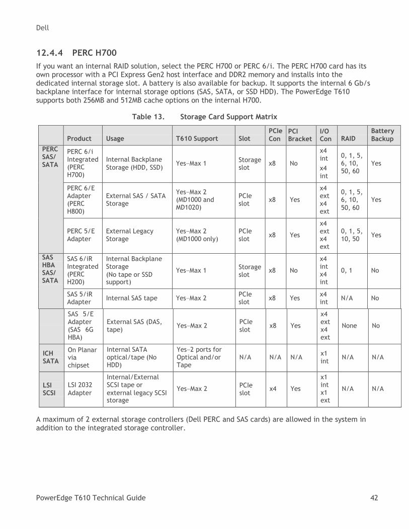
Dell
PowerEdge T610 Technical Guide 42
12.4.4 PERC H700
If you want an internal RAID solution, select the PERC H700 or PERC 6/i. The PERC H700 card has its own processor with a PCI Express Gen2 host interface and DDR2 memory and installs into the dedicated internal storage slot. A battery is also available for backup. It supports the internal 6 Gb/s backplane interface for internal storage options (SAS, SATA, or SSD HDD). The PowerEdge T610 supports both 256MB and 512MB cache options on the internal H700.
Storage Card Support Matrix Table 13.
Product
Usage
T610 Support
Slot
PCIe
Con PCI Bracket
I/O Con
RAID
Battery
Backup
PERC SAS/ SATA
PERC 6/i Integrated (PERC H700)
Internal Backplane
Storage (HDD, SSD)
Yes—Max 1
Storage slot
x8
No
x4 int
x4 int
0, 1, 5, 6, 10, 50, 60
Yes
PERC 6/E Adapter (PERC H800)
External SAS / SATA Storage
Yes—Max 2 (MD1000 and MD1020)
PCIe slot
x8
Yes
x4 ext x4 ext
0, 1, 5, 6, 10,
50, 60
Yes
PERC 5/E Adapter
External Legacy Storage
Yes—Max 2 (MD1000 only)
PCIe slot
x8
Yes
x4 ext x4 ext
0, 1, 5, 10, 50
Yes
SAS HBA SAS/ SATA
SAS 6/iR Integrated (PERC H200)
Internal Backplane Storage
(No tape or SSD support)
Yes—Max 1
Storage slot
x8
No
x4 int x4 int
0, 1
No
SAS 5/iR Adapter
Internal SAS tape
Yes—Max 2 PCIe slot
x8
Yes x4 int
N/A
No
SAS 5/E Adapter (SAS 6G HBA)
External SAS (DAS, tape)
Yes—Max 2
PCIe slot
x8
Yes
x4 ext x4 ext
None
No
ICH SATA
On Planar via chipset
Internal SATA optical/tape (No HDD)
Yes—2 ports for Optical and/or Tape
N/A
N/A
N/A
x1 int
N/A
N/A
LSI SCSI
LSI 2032
Adapter
Internal/External SCSI tape or
external legacy SCSI storage
Yes—Max 2
PCIe slot
x4
Yes
x1 int x1 ext
N/A
N/A
A maximum of 2 external storage controllers (Dell PERC and SAS cards) are allowed in the system in addition to the integrated storage controller.
Dell
PowerEdge T610 Technical Guide 43
12.5 Optical Drives
Optical drives are optional in all PowerEdge T610 systems and connect to the planar through the SATA interface. The following internal optical drives are available on the PowerEdge T610:
• DVD-ROM
• DVD+RW
If an optical drive is not ordered with the system, a blank is installed in its place. In the absence of a tape drive, an optional second SATA optical drive can be installed in the bay adjacent to the first optical drive. IDE (PATA) optical drives are not supported.
12.6 Tape Drives
The PowerEdge T610 supports a maximum of one half-height tape backup unit (TBU), which is optional in all T610 systems and connects to the planar SATA, SCSI controller card, or SAS controller card. IDE tape drives are not supported.
Internal and external tape drives and tape libraries are supported. For more information on supported tape drives and tape libraries, see Dell.com/storage.
12.7 External Storage Support
External storage devices are supported. For more information, see Dell.com/storage.
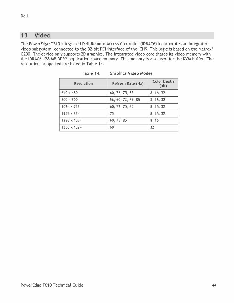
Dell
PowerEdge T610 Technical Guide 44
13 Video
The PowerEdge T610 Integrated Dell Remote Access Controller (iDRAC6) incorporates an integrated
video subsystem, connected to the 32-bit PCI interface of the ICH9. This logic is based on the Matrox®
G200. The device only supports 2D graphics. The integrated video core shares its video memory with the iDRAC6 128 MB DDR2 application space memory. This memory is also used for the KVM buffer. The resolutions supported are listed in Table 14.
Graphics Video Modes Table 14.
Resolution
Refresh Rate (Hz) Color Depth
(bit)
640 x 480 60, 72, 75, 85 8, 16, 32
800 x 600 56, 60, 72, 75, 85 8, 16, 32
1024 x 768 60, 72, 75, 85 8, 16, 32
1152 x 864 75 8, 16, 32
1280 x 1024 60, 75, 85 8, 16
1280 x 1024 60 32
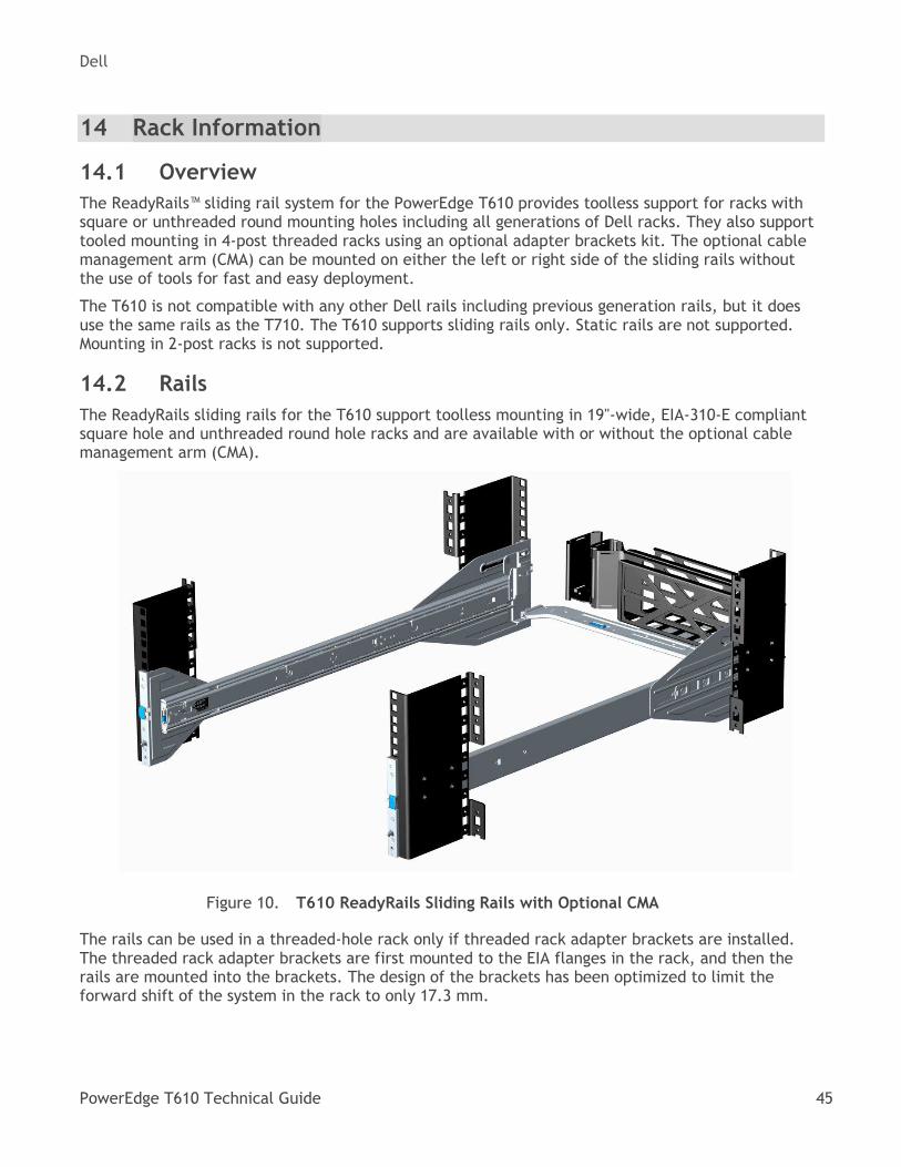
Dell
PowerEdge T610 Technical Guide 45
14 Rack Information
14.1 Overview
The ReadyRails™ sliding rail system for the PowerEdge T610 provides toolless support for racks with square or unthreaded round mounting holes including all generations of Dell racks. They also support tooled mounting in 4-post threaded racks using an optional adapter brackets kit. The optional cable management arm (CMA) can be mounted on either the left or right side of the sliding rails without the use of tools for fast and easy deployment.
The T610 is not compatible with any other Dell rails including previous generation rails, but it does use the same rails as the T710. The T610 supports sliding rails only. Static rails are not supported. Mounting in 2-post racks is not supported.
14.2 Rails
The ReadyRails sliding rails for the T610 support toolless mounting in 19"-wide, EIA-310-E compliant square hole and unthreaded round hole racks and are available with or without the optional cable management arm (CMA).
T610 ReadyRails Sliding Rails with Optional CMA Figure 10.
The rails can be used in a threaded-hole rack only if threaded rack adapter brackets are installed. The threaded rack adapter brackets are first mounted to the EIA flanges in the rack, and then the rails are mounted into the brackets. The design of the brackets has been optimized to limit the forward shift of the system in the rack to only 17.3 mm.
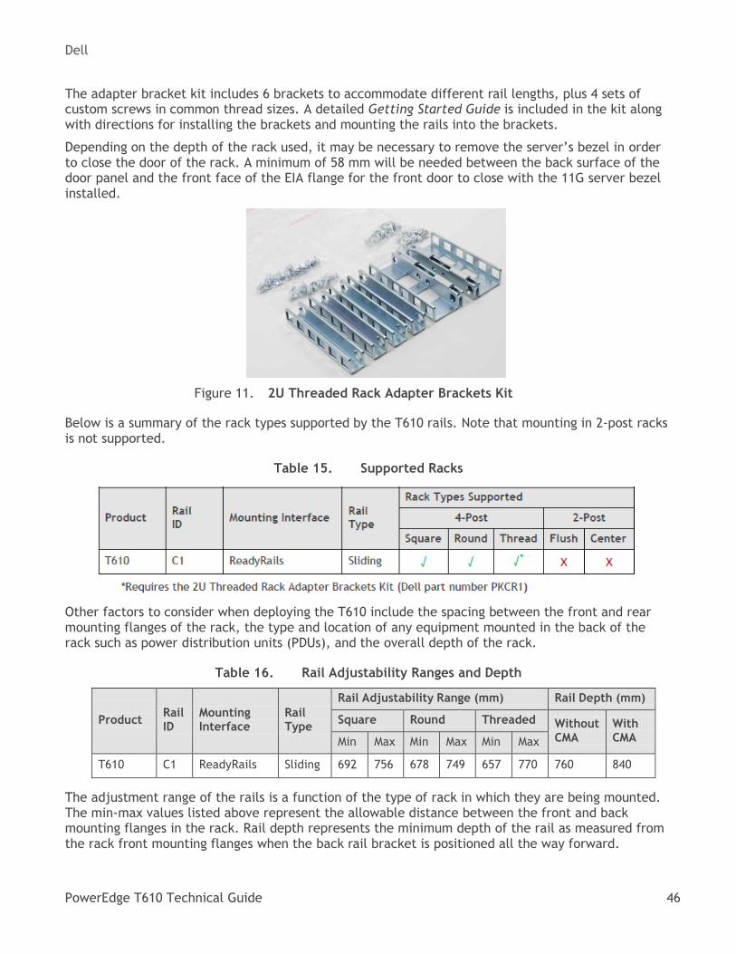
Dell
PowerEdge T610 Technical Guide 46
The adapter bracket kit includes 6 brackets to accommodate different rail lengths, plus 4 sets of custom screws in common thread sizes. A detailed Getting Started Guide is included in the kit along with directions for installing the brackets and mounting the rails into the brackets.
Depending on the depth of the rack used, it may be necessary to remove the server’s bezel in order to close the door of the rack. A minimum of 58 mm will be needed between the back surface of the door panel and the front face of the EIA flange for the front door to close with the 11G server bezel installed.
2U Threaded Rack Adapter Brackets Kit Figure 11.
Below is a summary of the rack types supported by the T610 rails. Note that mounting in 2-post racks is not supported.
Supported Racks Table 15.
Other factors to consider when deploying the T610 include the spacing between the front and rear mounting flanges of the rack, the type and location of any equipment mounted in the back of the rack such as power distribution units (PDUs), and the overall depth of the rack.
Rail Adjustability Ranges and Depth Table 16.
Product
Rail ID
Mounting Interface
Rail Type
Rail Adjustability Range (mm) Rail Depth (mm)
Square Round Threaded
Without CMA
With CMA Min Max Min Max Min Max
T610 C1 ReadyRails Sliding 692 756 678 749 657 770 760 840
The adjustment range of the rails is a function of the type of rack in which they are being mounted. The min-max values listed above represent the allowable distance between the front and back mounting flanges in the rack. Rail depth represents the minimum depth of the rail as measured from the rack front mounting flanges when the back rail bracket is positioned all the way forward.
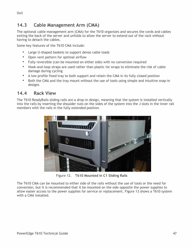
Dell
PowerEdge T610 Technical Guide 47
14.3 Cable Management Arm (CMA)
The optional cable management arm (CMA) for the T610 organizes and secures the cords and cables exiting the back of the server and unfolds to allow the server to extend out of the rack without having to detach the cables.
Some key features of the T610 CMA include:
• Large U-shaped baskets to support dense cable loads
• Open vent pattern for optimal airflow
• Fully reversible (can be mounted on either side) with no conversion required
• Hook-and-loop straps are used rather than plastic tie wraps to eliminate the risk of cable damage during cycling
• A low profile fixed tray to both support and retain the CMA in its fully closed position
• Both the CMA and the tray mount without the use of tools using simple and intuitive snap-in designs
14.4 Rack View
The T610 ReadyRails sliding rails are a drop-in design, meaning that the system is installed vertically into the rails by inserting the shoulder nuts on the sides of the system into the J-slots in the inner rail members with the rails in the fully extended position.
T610 Mounted in C1 Sliding Rails Figure 12.
The T610 CMA can be mounted to either side of the rails without the use of tools or the need for conversion, but it is recommended that it be mounted on the side opposite the power supplies to allow easier access to the power supplies for service or replacement. Figure 13 shows a T610 system with a CMA installed.
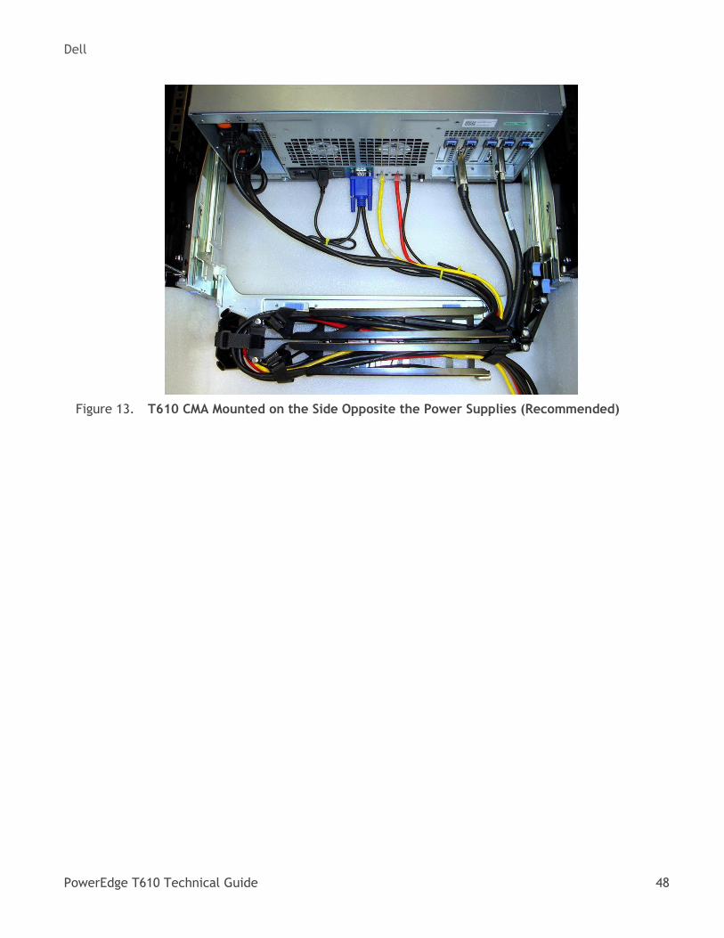
Dell
PowerEdge T610 Technical Guide 48
T610 CMA Mounted on the Side Opposite the Power Supplies (Recommended) Figure 13.
Dell
PowerEdge T610 Technical Guide 49
15 Operating Systems
For detailed information, see the following:
• Operating System Support Matrix for Dell PowerEdge Systems on Dell.com
• Dell PowerEdge T610 Systems Getting Started With Your System guide on Support.Dell.com
Dell
PowerEdge T610 Technical Guide 50
16 Systems Management
16.1 Overview
Dell delivers open, comprehensive, and integrated solutions that help you reduce the complexity of managing disparate IT assets. Combining Dell PowerEdge Servers with a wide selection of Dell developed systems management solutions gives you choice and flexibility, so you can simplify and save in IT environments of any size. To help you meet your server management demands, Dell offers Dell OpenManage™ systems management solutions for:
• Deployment of one or many servers from a single console
• Monitoring of server and storage health and maintenance
• Update of system, operating system, and application software
Dell offers IT management solutions for organizations of all sizes—priced and sized appropriately, and supported comprehensively.
16.2 Server Management
A Dell Systems Management and Documentation DVD and a Dell Management Console DVD are included with the product. ISO images are also available. A brief description of available content:
• Dell Systems Build and Update Utility (SBUU): Dell Systems Build and Update Utility assists in OS install and pre-OS hardware configuration and updates.
• Server Update Utility (SUU): This DVD has an inventory tool for managing updates to firmware, BIOS, and drivers for either Linux or Windows varieties.
• OpenManage Server Administrator (OMSA): The OpenManage Server Administrator tool provides a comprehensive, one-to-one (one console to one server) systems management solution, designed for system administrators to manage systems locally and remotely over a network. OMSA allows system administrators to focus on managing their entire network by providing comprehensive one-to-one systems management.
• Management Console: Dell IT Assistant (ITA) is also included, as well as tools to allow access to our remote management products. These tools are Remote Access Service for iDRAC and the Baseboard Management Controller (BMC) Utility.
• Active Directory Snap-in Utility: The Active Directory Snap-in Utility provides an extension snap-in to the Microsoft Active Directory. This allows you to manage Dell specific Active Directory objects. The Dell-specific schema class definitions and their installation are also included on the DVD.
• Dell Systems Service Diagnostics Tools: Dell Systems Service and Diagnostics tools deliver the latest Dell optimized drivers, utilities, and operating system-based diagnostics that you can use to update your system.
• eDocs: The section includes PDF files for PowerEdge systems, storage peripherals, and Dell OpenManage™ software.
• Dell Management Console (DMC): The Dell Management Console is a systems management console that enables systems administrators to discover and inventory devices on your network. It provides functions such as health and performance monitoring of networked devices, and patch management capabilities for Dell systems. DMC differs from the IT Assistant management console (described above) in that with DMC, value-add plug-ins that enable advanced functionality can be purchased and added to the base DMC product.
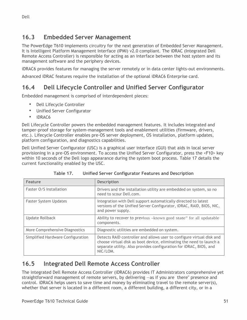
Dell
PowerEdge T610 Technical Guide 51
16.3 Embedded Server Management
The PowerEdge T610 implements circuitry for the next generation of Embedded Server Management. It is Intelligent Platform Management Interface (IPMI) v2.0 compliant. The iDRAC (Integrated Dell Remote Access Controller) is responsible for acting as an interface between the host system and its management software and the periphery devices.
iDRAC6 provides features for managing the server remotely or in data center lights-out environments.
Advanced iDRAC features require the installation of the optional iDRAC6 Enterprise card.
16.4 Dell Lifecycle Controller and Unified Server Configurator
Embedded management is comprised of interdependent pieces:
• Dell Lifecycle Controller
• Unified Server Configurator
• iDRAC6
Dell Lifecycle Controller powers the embedded management features. It includes integrated and tamper-proof storage for system-management tools and enablement utilities (firmware, drivers, etc.). Lifecycle Controller enables pre-OS server deployment, OS installation, platform updates, platform configuration, and diagnostics capabilities.
Dell Unified Server Configurator (USC) is a graphical user interface (GUI) that aids in local server provisioning in a pre-OS environment. To access the Unified Server Configurator, press the <F10> key within 10 seconds of the Dell logo appearance during the system boot process. Table 17 details the current functionality enabled by the USC.
Unified Server Configurator Features and Description Table 17.
Feature Description
Faster O/S Installation Drivers and the installation utility are embedded on system, so no need to scour Dell.com.
Faster System Updates Integration with Dell support automatically directed to latest versions of the Unified Server Configurator, iDRAC, RAID, BIOS, NIC, and power supply.
Update Rollback Ability to recover to previous ―known good state" for all updatable
components.
More Comprehensive Diagnostics Diagnostic utilities are embedded on system.
Simplified Hardware Configuration Detects RAID controller and allows user to configure virtual disk and choose virtual disk as boot device, eliminating the need to launch a separate utility. Also provides configuration for iDRAC, BIOS, and NIC/LOM.
16.5 Integrated Dell Remote Access Controller
The integrated Dell Remote Access Controller (iDRAC6) provides IT Administrators comprehensive yet straightforward management of remote servers, by delivering ―as if you are there" presence and
control. iDRAC6 helps users to save time and money by eliminating travel to the remote server(s), whether that server is located in a different room, a different building, a different city, or in a
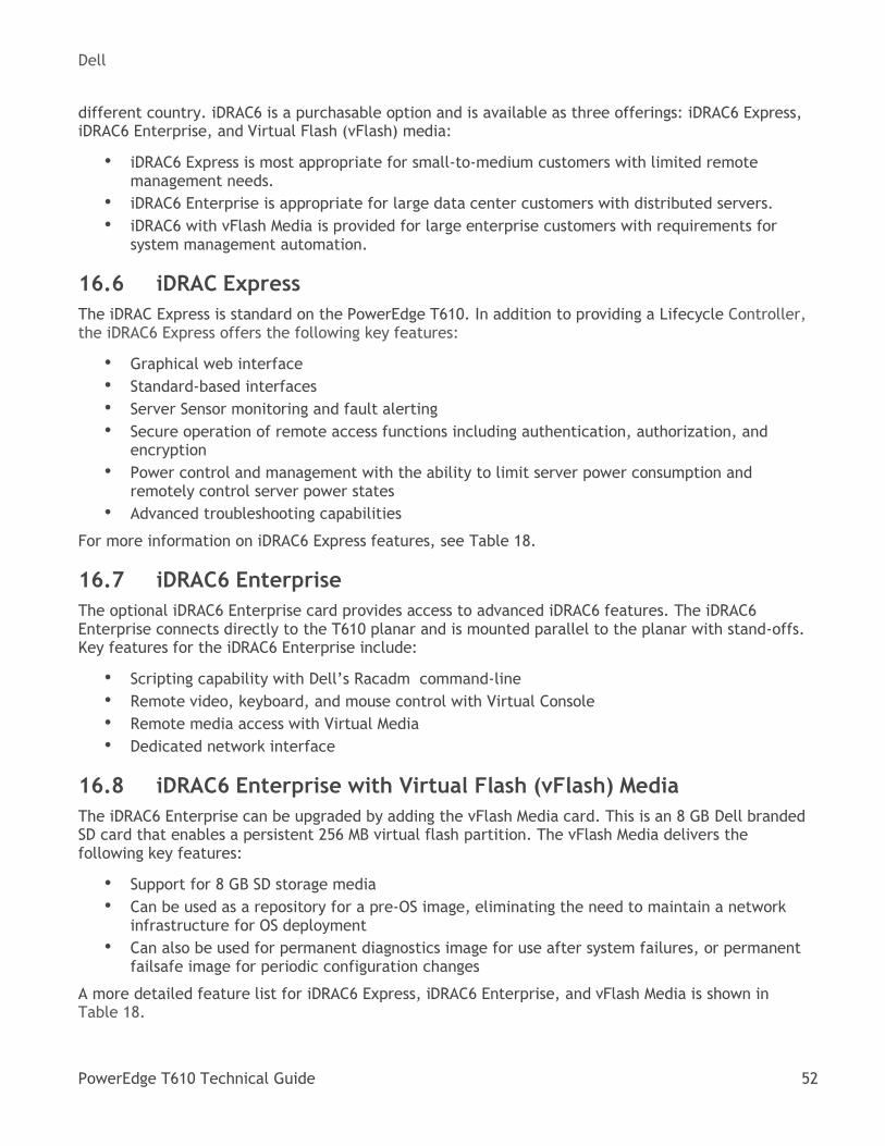
Dell
PowerEdge T610 Technical Guide 52
different country. iDRAC6 is a purchasable option and is available as three offerings: iDRAC6 Express, iDRAC6 Enterprise, and Virtual Flash (vFlash) media:
• iDRAC6 Express is most appropriate for small-to-medium customers with limited remote management needs.
• iDRAC6 Enterprise is appropriate for large data center customers with distributed servers.
• iDRAC6 with vFlash Media is provided for large enterprise customers with requirements for system management automation.
16.6 iDRAC Express
The iDRAC Express is standard on the PowerEdge T610. In addition to providing a Lifecycle Controller, the iDRAC6 Express offers the following key features:
• Graphical web interface
• Standard-based interfaces
• Server Sensor monitoring and fault alerting
• Secure operation of remote access functions including authentication, authorization, and encryption
• Power control and management with the ability to limit server power consumption and remotely control server power states
• Advanced troubleshooting capabilities
For more information on iDRAC6 Express features, see Table 18.
16.7 iDRAC6 Enterprise
The optional iDRAC6 Enterprise card provides access to advanced iDRAC6 features. The iDRAC6 Enterprise connects directly to the T610 planar and is mounted parallel to the planar with stand-offs. Key features for the iDRAC6 Enterprise include:
• Scripting capability with Dell’s Racadm command-line
• Remote video, keyboard, and mouse control with Virtual Console
• Remote media access with Virtual Media
• Dedicated network interface
16.8 iDRAC6 Enterprise with Virtual Flash (vFlash) Media
The iDRAC6 Enterprise can be upgraded by adding the vFlash Media card. This is an 8 GB Dell branded SD card that enables a persistent 256 MB virtual flash partition. The vFlash Media delivers the following key features:
• Support for 8 GB SD storage media
• Can be used as a repository for a pre-OS image, eliminating the need to maintain a network infrastructure for OS deployment
• Can also be used for permanent diagnostics image for use after system failures, or permanent failsafe image for periodic configuration changes
A more detailed feature list for iDRAC6 Express, iDRAC6 Enterprise, and vFlash Media is shown in Table 18.
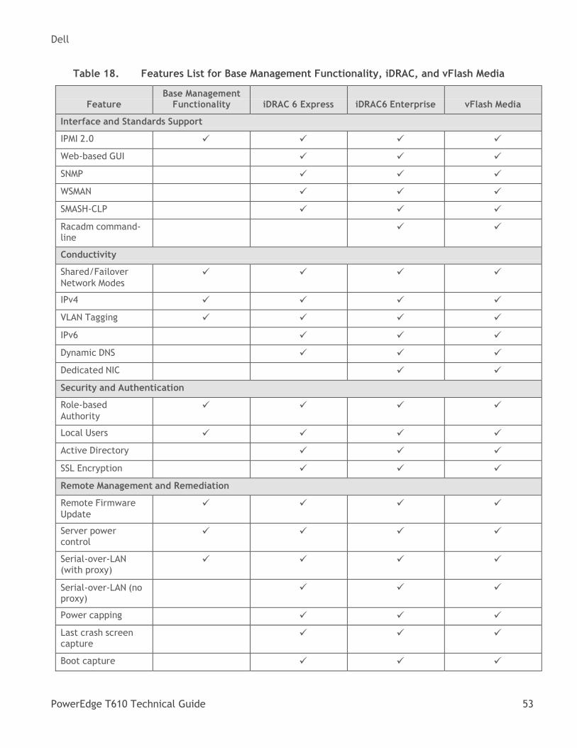
Dell
PowerEdge T610 Technical Guide 53
Features List for Base Management Functionality, iDRAC, and vFlash Media Table 18.
Feature
Base Management Functionality
iDRAC 6 Express
iDRAC6 Enterprise
vFlash Media
Interface and Standards Support
IPMI 2.0
Web-based GUI
SNMP
WSMAN
SMASH-CLP
Racadm command- line
Conductivity
Shared/Failover
Network Modes
IPv4
VLAN Tagging
IPv6
Dynamic DNS
Dedicated NIC
Security and Authentication
Role-based
Authority
Local Users
Active Directory
SSL Encryption
Remote Management and Remediation
Remote Firmware
Update
Server power control
Serial-over-LAN (with proxy)
Serial-over-LAN (no proxy)
Power capping
Last crash screen capture
Boot capture
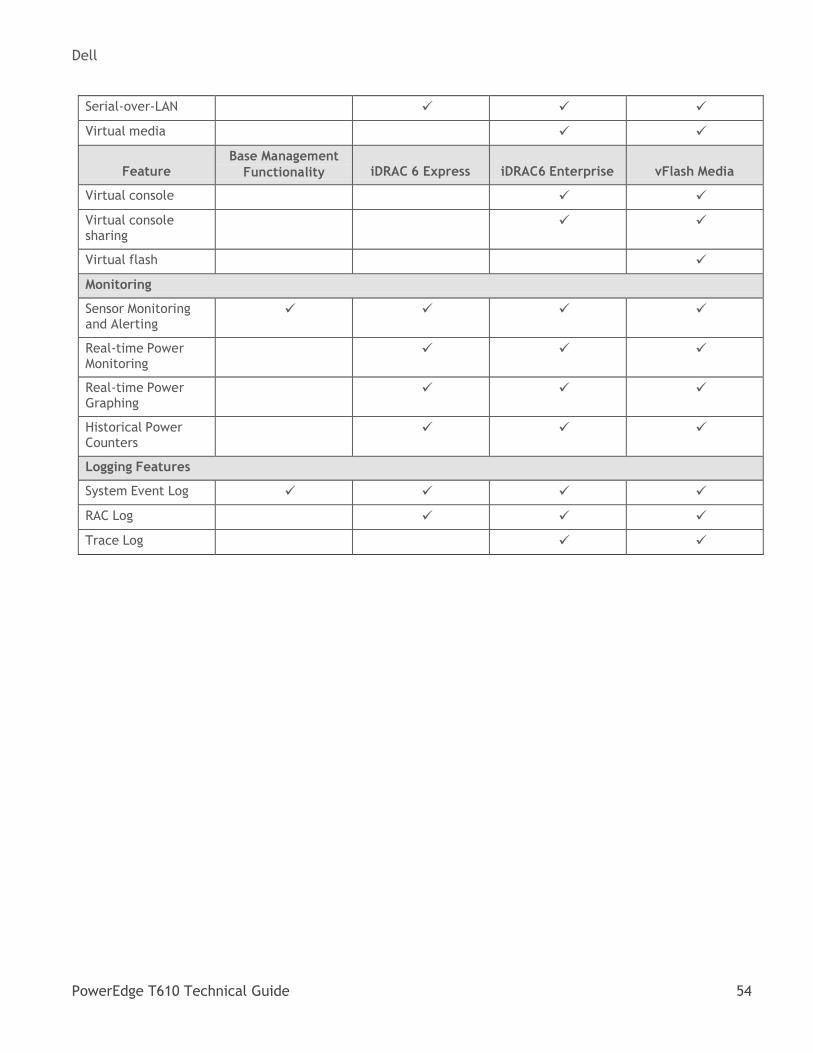
Dell
PowerEdge T610 Technical Guide 54
Serial-over-LAN
Virtual media
Feature
Base Management
Functionality
iDRAC 6 Express
iDRAC6 Enterprise
vFlash Media
Virtual console
Virtual console sharing
Virtual flash
Monitoring
Sensor Monitoring and Alerting
Real-time Power Monitoring
Real-time Power Graphing
Historical Power Counters
Logging Features
System Event Log
RAC Log
Trace Log
Dell
PowerEdge T610 Technical Guide 55
17 Peripherals
The T610 supports the following USB devices:
• DVD (bootable; requires two USB ports)
• USB key (bootable)
• Keyboard (only one USB keyboard is supported)
• Mouse (only one USB mouse is supported)
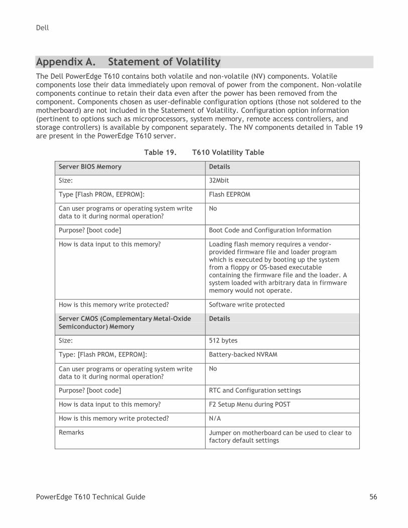
Dell
PowerEdge T610 Technical Guide 56
Appendix A. Statement of Volatility
The Dell PowerEdge T610 contains both volatile and non-volatile (NV) components. Volatile components lose their data immediately upon removal of power from the component. Non-volatile components continue to retain their data even after the power has been removed from the component. Components chosen as user-definable configuration options (those not soldered to the motherboard) are not included in the Statement of Volatility. Configuration option information (pertinent to options such as microprocessors, system memory, remote access controllers, and storage controllers) is available by component separately. The NV components detailed in Table 19 are present in the PowerEdge T610 server.
T610 Volatility Table Table 19.
Server BIOS Memory Details
Size: 32Mbit
Type [Flash PROM, EEPROM]: Flash EEPROM
Can user programs or operating system write data to it during normal operation?
No
Purpose? [boot code] Boot Code and Configuration Information
How is data input to this memory? Loading flash memory requires a vendor- provided firmware file and loader program which is executed by booting up the system from a floppy or OS-based executable containing the firmware file and the loader. A system loaded with arbitrary data in firmware memory would not operate.
How is this memory write protected? Software write protected
Server CMOS (Complementary Metal-Oxide
Semiconductor) Memory
Details
Size: 512 bytes
Type: [Flash PROM, EEPROM]: Battery-backed NVRAM
Can user programs or operating system write data to it during normal operation?
No
Purpose? [boot code] RTC and Configuration settings
How is data input to this memory? F2 Setup Menu during POST
How is this memory write protected? N/A
Remarks Jumper on motherboard can be used to clear to factory default settings
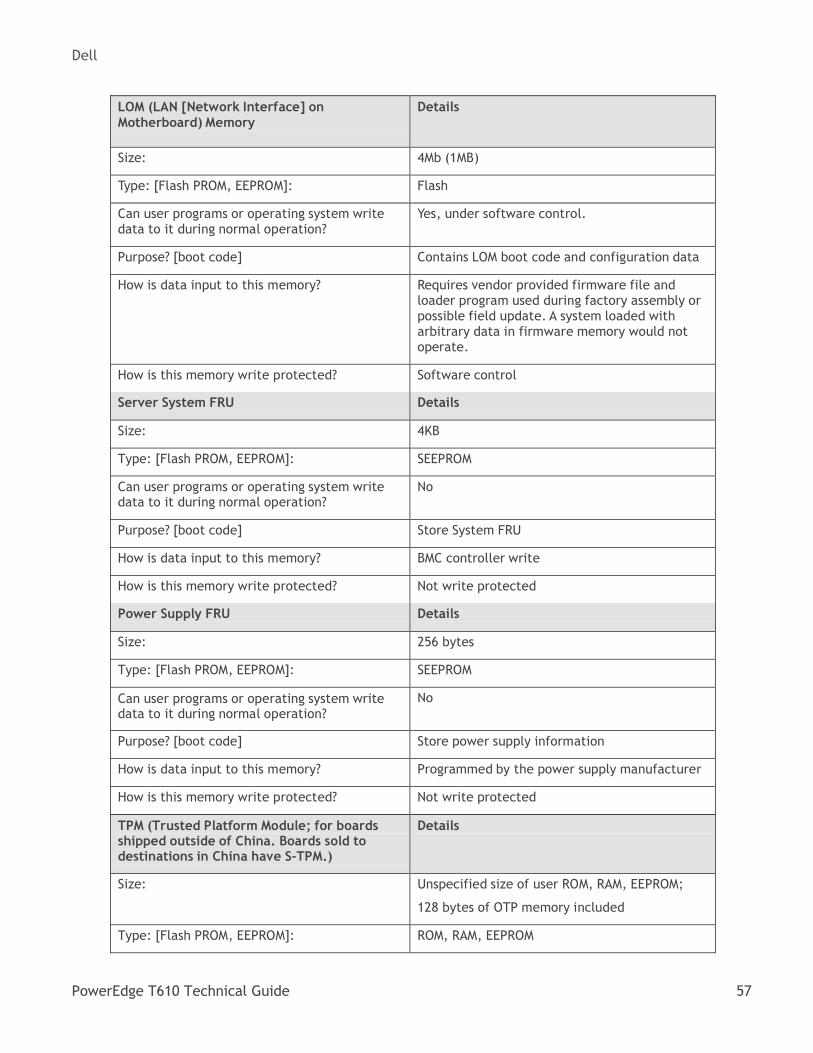
Dell
PowerEdge T610 Technical Guide 57
LOM (LAN [Network Interface] on
Motherboard) Memory
Details
Size: 4Mb (1MB)
Type: [Flash PROM, EEPROM]: Flash
Can user programs or operating system write data to it during normal operation?
Yes, under software control.
Purpose? [boot code] Contains LOM boot code and configuration data
How is data input to this memory? Requires vendor provided firmware file and loader program used during factory assembly or possible field update. A system loaded with arbitrary data in firmware memory would not operate.
How is this memory write protected? Software control
Server System FRU Details
Size: 4KB
Type: [Flash PROM, EEPROM]: SEEPROM
Can user programs or operating system write data to it during normal operation?
No
Purpose? [boot code] Store System FRU
How is data input to this memory? BMC controller write
How is this memory write protected? Not write protected
Power Supply FRU Details
Size: 256 bytes
Type: [Flash PROM, EEPROM]: SEEPROM
Can user programs or operating system write data to it during normal operation?
No
Purpose? [boot code] Store power supply information
How is data input to this memory? Programmed by the power supply manufacturer
How is this memory write protected? Not write protected
TPM (Trusted Platform Module; for boards shipped outside of China. Boards sold to destinations in China have S-TPM.)
Details
Size: Unspecified size of user ROM, RAM, EEPROM;
128 bytes of OTP memory included
Type: [Flash PROM, EEPROM]: ROM, RAM, EEPROM
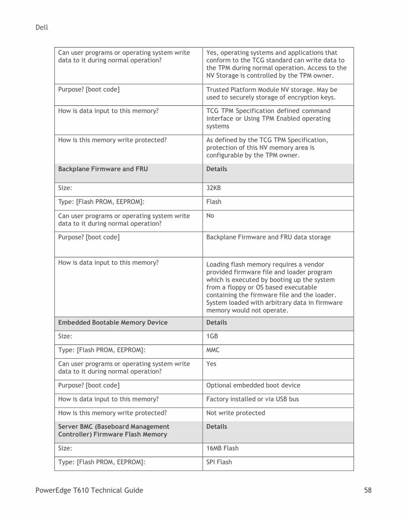
Dell
PowerEdge T610 Technical Guide 58
Can user programs or operating system write data to it during normal operation?
Yes, operating systems and applications that conform to the TCG standard can write data to the TPM during normal operation. Access to the NV Storage is controlled by the TPM owner.
Purpose? [boot code] Trusted Platform Module NV storage. May be used to securely storage of encryption keys.
How is data input to this memory? TCG TPM Specification defined command interface or Using TPM Enabled operating systems
How is this memory write protected? As defined by the TCG TPM Specification, protection of this NV memory area is configurable by the TPM owner.
Backplane Firmware and FRU Details
Size: 32KB
Type: [Flash PROM, EEPROM]: Flash
Can user programs or operating system write data to it during normal operation?
No
Purpose? [boot code] Backplane Firmware and FRU data storage
How is data input to this memory?
Loading flash memory requires a vendor provided firmware file and loader program which is executed by booting up the system from a floppy or OS based executable containing the firmware file and the loader. System loaded with arbitrary data in firmware memory would not operate.
Embedded Bootable Memory Device Details
Size: 1GB
Type: [Flash PROM, EEPROM]: MMC
Can user programs or operating system write data to it during normal operation?
Yes
Purpose? [boot code] Optional embedded boot device
How is data input to this memory? Factory installed or via USB bus
How is this memory write protected? Not write protected
Server BMC (Baseboard Management
Controller) Firmware Flash Memory
Details
Size: 16MB Flash
Type: [Flash PROM, EEPROM]: SPI Flash
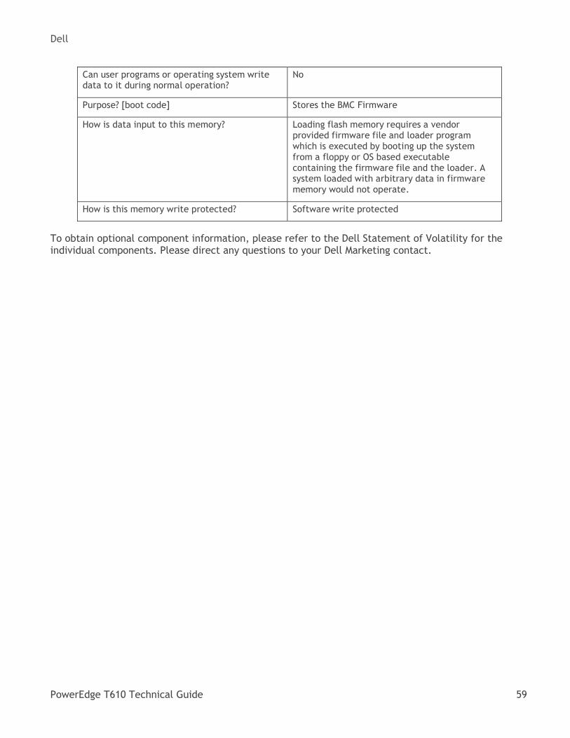
Dell
PowerEdge T610 Technical Guide 59
Can user programs or operating system write data to it during normal operation?
No
Purpose? [boot code] Stores the BMC Firmware
How is data input to this memory? Loading flash memory requires a vendor provided firmware file and loader program which is executed by booting up the system from a floppy or OS based executable containing the firmware file and the loader. A system loaded with arbitrary data in firmware memory would not operate.
How is this memory write protected? Software write protected
To obtain optional component information, please refer to the Dell Statement of Volatility for the individual components. Please direct any questions to your Dell Marketing contact.
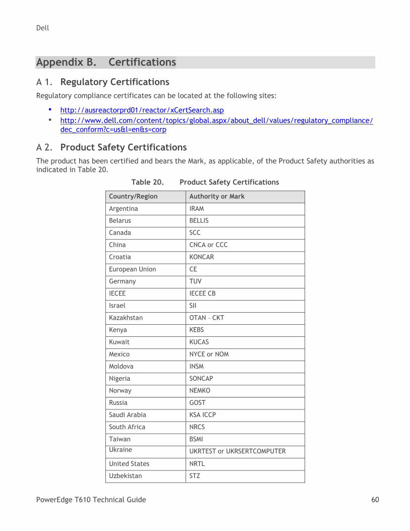
Dell
PowerEdge T610 Technical Guide 60
Appendix B. Certifications
Regulatory Certifications A 1.
Regulatory compliance certificates can be located at the following sites:
• http://ausreactorprd01/reactor/xCertSearch.asp
• http://www.dell.com/content/topics/global.aspx/about_dell/values/regulatory_compliance/dec_conform?c=us&l=en&s=corp
Product Safety Certifications A 2.
The product has been certified and bears the Mark, as applicable, of the Product Safety authorities as indicated in Table 20.
Product Safety Certifications Table 20.
Country/Region Authority or Mark
Argentina IRAM
Belarus BELLIS
Canada SCC
China CNCA or CCC
Croatia KONCAR
European Union CE
Germany TUV
IECEE IECEE CB
Israel SII
Kazakhstan OTAN – CKT
Kenya KEBS
Kuwait KUCAS
Mexico NYCE or NOM
Moldova INSM
Nigeria SONCAP
Norway NEMKO
Russia GOST
Saudi Arabia KSA ICCP
South Africa NRCS
Taiwan BSMI
Ukraine UKRTEST or UKRSERTCOMPUTER
United States NRTL
Uzbekistan STZ
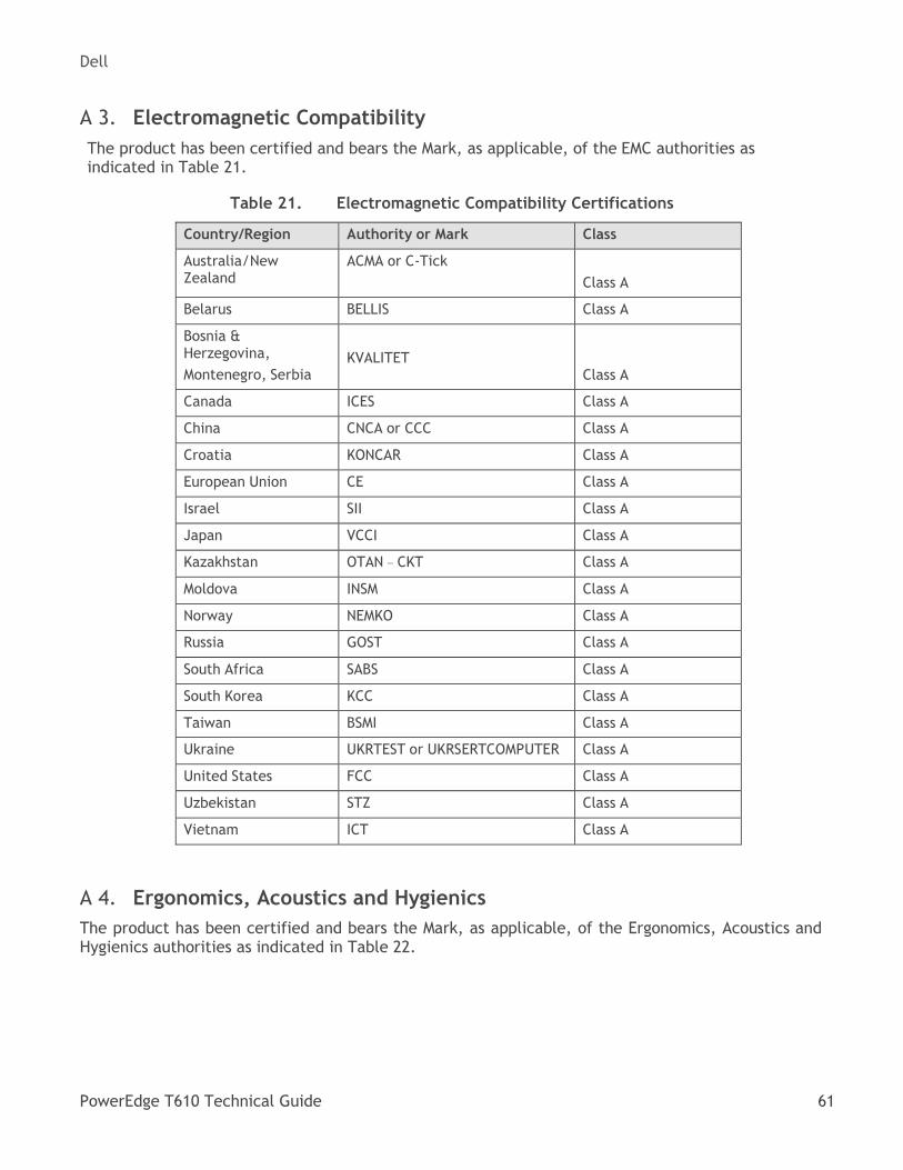
Dell
PowerEdge T610 Technical Guide 61
Electromagnetic Compatibility A 3.
The product has been certified and bears the Mark, as applicable, of the EMC authorities as indicated in Table 21.
Electromagnetic Compatibility Certifications Table 21.
Country/Region Authority or Mark Class
Australia/New Zealand
ACMA or C-Tick
Class A
Belarus BELLIS Class A
Bosnia & Herzegovina,
Montenegro, Serbia
KVALITET
Class A
Canada ICES Class A
China CNCA or CCC Class A
Croatia KONCAR Class A
European Union CE Class A
Israel SII Class A
Japan VCCI Class A
Kazakhstan OTAN – CKT Class A
Moldova INSM Class A
Norway NEMKO Class A
Russia GOST Class A
South Africa SABS Class A
South Korea KCC Class A
Taiwan BSMI Class A
Ukraine UKRTEST or UKRSERTCOMPUTER Class A
United States FCC Class A
Uzbekistan STZ Class A
Vietnam ICT Class A
Ergonomics, Acoustics and Hygienics A 4.
The product has been certified and bears the Mark, as applicable, of the Ergonomics, Acoustics and Hygienics authorities as indicated in Table 22.
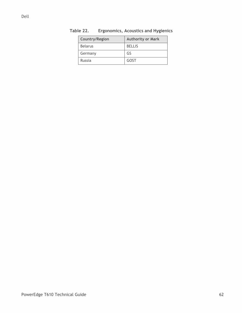
Dell
PowerEdge T610 Technical Guide 62
Ergonomics, Acoustics and Hygienics Table 22.
Country/Region Authority or Mark
Belarus BELLIS
Germany GS
Russia GOST
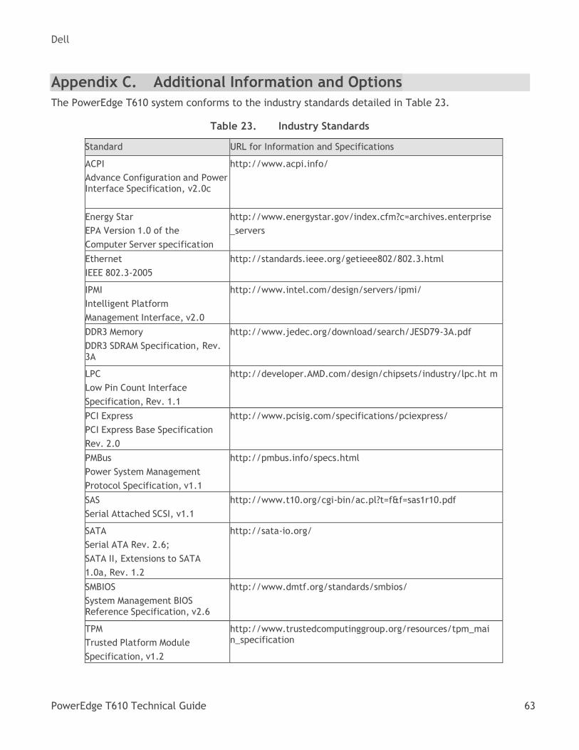
Dell
PowerEdge T610 Technical Guide 63
Appendix C. Additional Information and Options
The PowerEdge T610 system conforms to the industry standards detailed in Table 23.
Industry Standards Table 23.
Standard URL for Information and Specifications
ACPI
Advance Configuration and Power Interface Specification, v2.0c
http://www.acpi.info/
Energy Star
EPA Version 1.0 of the
Computer Server specification
http://www.energystar.gov/index.cfm?c=archives.enterprise
_servers
Ethernet
IEEE 802.3-2005
http://standards.ieee.org/getieee802/802.3.html
IPMI
Intelligent Platform
Management Interface, v2.0
http://www.intel.com/design/servers/ipmi/
DDR3 Memory
DDR3 SDRAM Specification, Rev. 3A
http://www.jedec.org/download/search/JESD79-3A.pdf
LPC
Low Pin Count Interface
Specification, Rev. 1.1
http://developer.AMD.com/design/chipsets/industry/lpc.ht m
PCI Express
PCI Express Base Specification
Rev. 2.0
http://www.pcisig.com/specifications/pciexpress/
PMBus
Power System Management
Protocol Specification, v1.1
http://pmbus.info/specs.html
SAS
Serial Attached SCSI, v1.1
http://www.t10.org/cgi-bin/ac.pl?t=f&f=sas1r10.pdf
SATA
Serial ATA Rev. 2.6;
SATA II, Extensions to SATA
1.0a, Rev. 1.2
http://sata-io.org/
SMBIOS
System Management BIOS Reference Specification, v2.6
http://www.dmtf.org/standards/smbios/
TPM
Trusted Platform Module
Specification, v1.2
http://www.trustedcomputinggroup.org/resources/tpm_mai n_specification
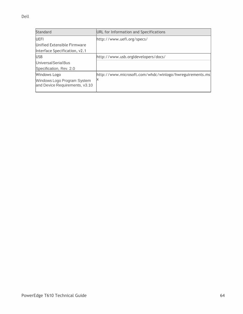
Dell
PowerEdge T610 Technical Guide 64
Standard URL for Information and Specifications
UEFI
Unified Extensible Firmware
Interface Specification, v2.1
http://www.uefi.org/specs/
USB
UniversalSerial Bus
Specification, Rev. 2.0
http://www.usb.orgIdevelopers/docs/
Windows Logo
Windows Logo Program System and Device Requirements, v3.10
http://www.microsoft.com/whdc/winlogo/hwreguirements.msx