Embed Size (px)
Citation preview
PowerEdge T620 Technical Guide
An enterprise-class,
two-socket tower server
with balanced high
performance, high
availability and built-in
room for growth.
ii PowerEdge R620 Technical Guide
This document is for informational purposes only. Dell reserves the right to make changes without further notice to any products herein. The content provided is as is and without express or implied warranties of any kind.
Dell, the DELL logo, PowerEdge, EqualLogic, PowerVault, OpenManage, KACE and ReadyRails are trademarks of Dell, Inc. Intel and Xeon are registered trademarks of Intel Corporation in the U.S. and other countries. Microsoft, Windows, Windows Server, SQL Server, BitLocker, ActiveX, Internet Explorer and Hyper-V are either registered trademarks or trademarks of Microsoft Corporation in the United States and/or other countries. Novell and SUSE are registered trademarks of Novell, Inc. in the United States and other countries. IBM and Tivoli are registered trademarks of IBM in the United States. AMD and combinations thereof, are trademarks of Advanced Micro Devices, Inc. Other trademarks and trade names may be used in this document to refer to either the entities claiming the marks and names or their products. Dell disclaims proprietary interest in the marks and names of others.
©Copyright 2013 Dell Inc. All rights reserved. Reproduction or translation of any part of this work beyond that permitted by U.S. copyright laws without the written permission of Dell Inc. is unlawful and strictly forbidden.
December 2013 | Version 5.0
iii PowerEdge R620 Technical Guide
Table of contents
1 System overview ................................................................................................................................................................. 6 Introduction ........................................................................................................................................................................ 6 Key technologies ................................................................................................................................................................ 7
2 System features .................................................................................................................................................................. 8 Comparison of PowerEdge systems .............................................................................................................................. 8 Specifications ..................................................................................................................................................................... 9
3 Chassis views and features .............................................................................................................................................. 12 Chassis views ..................................................................................................................................................................... 12 Chassis features ................................................................................................................................................................ 15
4 Processor ............................................................................................................................................................................18 Processor features ............................................................................................................................................................18 Supported processors ...................................................................................................................................................... 19 GPU support ..................................................................................................................................................................... 20 Chipset ................................................................................................................................................................................ 21
5 Memory .............................................................................................................................................................................. 22 Supported memory ......................................................................................................................................................... 22 Memory configurations .................................................................................................................................................. 23 Memory speed ................................................................................................................................................................. 23 Memory RAS features...................................................................................................................................................... 24
6 Storage ............................................................................................................................................................................... 26 Internal storage ................................................................................................................................................................ 26 External storage ............................................................................................................................................................... 27 Storage controllers .......................................................................................................................................................... 28 Optical drive ..................................................................................................................................................................... 29 Tape drive .......................................................................................................................................................................... 30
7 Networking and PCIe ....................................................................................................................................................... 31 Embedded NIC controller ............................................................................................................................................... 31 PCIe expansion ................................................................................................................................................................. 31
8 Power, thermal and acoustics ....................................................................................................................................... 33 Power consumption and energy efficiency ................................................................................................................ 33 Power supply units .......................................................................................................................................................... 34 Thermal and acoustics.................................................................................................................................................... 35
9 Rack rails and cable management ................................................................................................................................ 38 Sliding rail system ............................................................................................................................................................ 38 Cable management arm................................................................................................................................................. 39
10 Operating systems and virtualization ........................................................................................................................... 40 Supported operating systems ........................................................................................................................................ 40 Supported virtualization ..................................................................................................................................................41
11 Dell OpenManage systems management .................................................................................................................... 42 Systems management solutions ................................................................................................................................... 42 OpenManage systems management ........................................................................................................................... 43 Dell server management operations ............................................................................................................................ 47
Appendix A. Additional specifications and options ................................................................................................... 50 Chassis dimensions ......................................................................................................................................................... 50 Chassis weight.................................................................................................................................................................. 50 Environmental specifications ......................................................................................................................................... 51 Power supply specifications .......................................................................................................................................... 52 Rack rail specifications ................................................................................................................................................... 52 Video specifications ........................................................................................................................................................ 53 USB peripherals ................................................................................................................................................................ 53
iv PowerEdge R620 Technical Guide
Appendix B. Standards compliance ............................................................................................................................. 54
Appendix C. Additional resources ................................................................................................................................. 56
Appendix D. System board block diagram .................................................................................................................. 58
Tables Table 1. Key technologies ................................................................................................................................................... 7 Table 2. Comparison of PowerEdge T610, T710 and T620 ......................................................................................... 8 Table 3. Technical specifications ...................................................................................................................................... 9 Table 4. Chassis features ................................................................................................................................................... 15 Table 5. Security features .................................................................................................................................................. 17 Table 6. Supported processors ........................................................................................................................................ 19 Table 7. GPU cards supported ........................................................................................................................................ 20 Table 8. Memory technologies supported .................................................................................................................... 22 Table 9. DIMMs supported ............................................................................................................................................... 23 Table 10. Memory speed capabilities ............................................................................................................................... 24 Table 11. Memory RAS features ........................................................................................................................................ 24 Table 12. Supported hard drives ....................................................................................................................................... 26 Table 13. Supported external storage .............................................................................................................................. 27 Table 14. RAID controllers ................................................................................................................................................. 28 Table 15. Hard-drive backplane options ......................................................................................................................... 29 Table 16. Tape devices supported .................................................................................................................................... 30 Table 17. Supported NICs and HBAs ................................................................................................................................. 31 Table 18. Additional supported PCIe expansion cards ................................................................................................. 32 Table 19. Power tools and technologies ......................................................................................................................... 33 Table 20. Power supply efficiency .................................................................................................................................... 35 Table 21. Acoustical performance .................................................................................................................................... 37 Table 22. T620 supported rack rail system ..................................................................................................................... 39 Table 23. Primary operating system support .................................................................................................................. 40 Table 24. Virtual guest operating system support ..........................................................................................................41 Table 25. Virtualization support .........................................................................................................................................41 Table 26. iDRAC7 with Lifecycle Controller functions and benefits ........................................................................... 43 Table 27. Feature comparison for iDRAC7 Express and Enterprise ............................................................................ 44 Table 28. One-to-one and one-to-many operations .................................................................................................. 48 Table 29. Tower and rack chassis weight ........................................................................................................................ 50 Table 30. Environmental specifications ............................................................................................................................ 51 Table 31. Power supply specifications ............................................................................................................................. 52 Table 32. Rail adjustability range ....................................................................................................................................... 52 Table 33. Supported video modes .................................................................................................................................... 53 Table 34. Industry standards documents ........................................................................................................................ 54 Table 35. Additional resources .......................................................................................................................................... 56
Figures
Figure 1. Front view without bezel ................................................................................................................................... 12 Figure 2. Front view with bezel.......................................................................................................................................... 13 Figure 3. Rackable front view without bezel ................................................................................................................... 13 Figure 4. Back view ..............................................................................................................................................................14 Figure 5. Internal view .........................................................................................................................................................14 Figure 6. Tower system with LCD panel .......................................................................................................................... 16 Figure 7. Rack system with VGA port ............................................................................................................................... 16 Figure 8. QRL code inside chassis cover ......................................................................................................................... 16 Figure 9. 750W power supply unit ................................................................................................................................... 35 Figure 10. Sliding rails with optional CMA ........................................................................................................................ 38 Figure 11. Dell systems management solutions .............................................................................................................. 42 Figure 12. Systems management server lifecycle ........................................................................................................... 48
v PowerEdge R620 Technical Guide
Figure 13. Tower and rack chassis dimensions ............................................................................................................... 50 Figure 14. T620 system board block diagram ................................................................................................................. 58
6 PowerEdge T620 Technical Guide
1 System overview
Introduction
The Dell™ PowerEdge™ T620 is a feature-rich, two-socket tower server with up to 24 DIMM slots, storage capacity of up to 32 2.5-inch or 12 3.5-inch drive bays, and processing power from the Intel® Xeon®
processor E5-2600 or E5-2600 v2 product families. The T620 shines in its ability to handle demanding workloads with up to 16 processor cores, high memory density, and high I/O bandwidth. The T620 is an excellent platform for key applications such as business analytics and intelligence, information management, customer relationship management, security management, desktop virtualization, medical imaging, and graphical rendering.
Designed for demanding small- and medium-sized business environments and enterprise data centers
The extensive 768GB memory footprint, large local storage capacity, and I/O flexibility of the PowerEdge T620 make it an attractive platform for a wide range of applications and workloads, including server consolidation and virtualization. The T620 features allow you to achieve space savings, use your IT administrator’s time more efficiently, and minimize potential software licensing fees.
The T620 is a flexible server with excellent energy efficiency and acoustical performance, allowing it to be placed into quiet office settings. The T620 can also be rack-mounted and is fully compatible with rack infrastructures. Businesses and organizations with remote offices need not worry, as the T620 offers consistent worldwide support.
Safeguard your data and business
Features that protect data and help keep your server running are essential. The T620 and its large storage capacity offer both software-based RAID and hardware RAID controller options to protect critical business information. Features that help to keep your business up and running include reliability, availability, and serviceability (RAS) options like hot-pluggable fans, disks, and power supplies, along with redundant, failsafe hypervisors that minimize the need to take a server away from productive work to replace parts.
Simplified systems management, without compromise
The Dell OpenManage™ systems management portfolio includes Integrated Dell Remote Access Controller 7 (iDRAC7) with Lifecycle Controller. This embedded feature helps IT administrators manage Dell servers in physical, virtual, local and remote environments, operating in-band or out-of-band, with or without a systems management software agent installed.
OpenManage iDRAC with Lifecycle Controller integrates and connects to leading third-party systems management solutions (such as those from Microsoft, VMware and BMC Software), so users can maintain a single point of control and capitalize on an existing systems management investment. OpenManage simplifies the lifecycle of deploying, updating, monitoring and maintaining Dell PowerEdge servers.
7 PowerEdge T620 Technical Guide
Key technologies
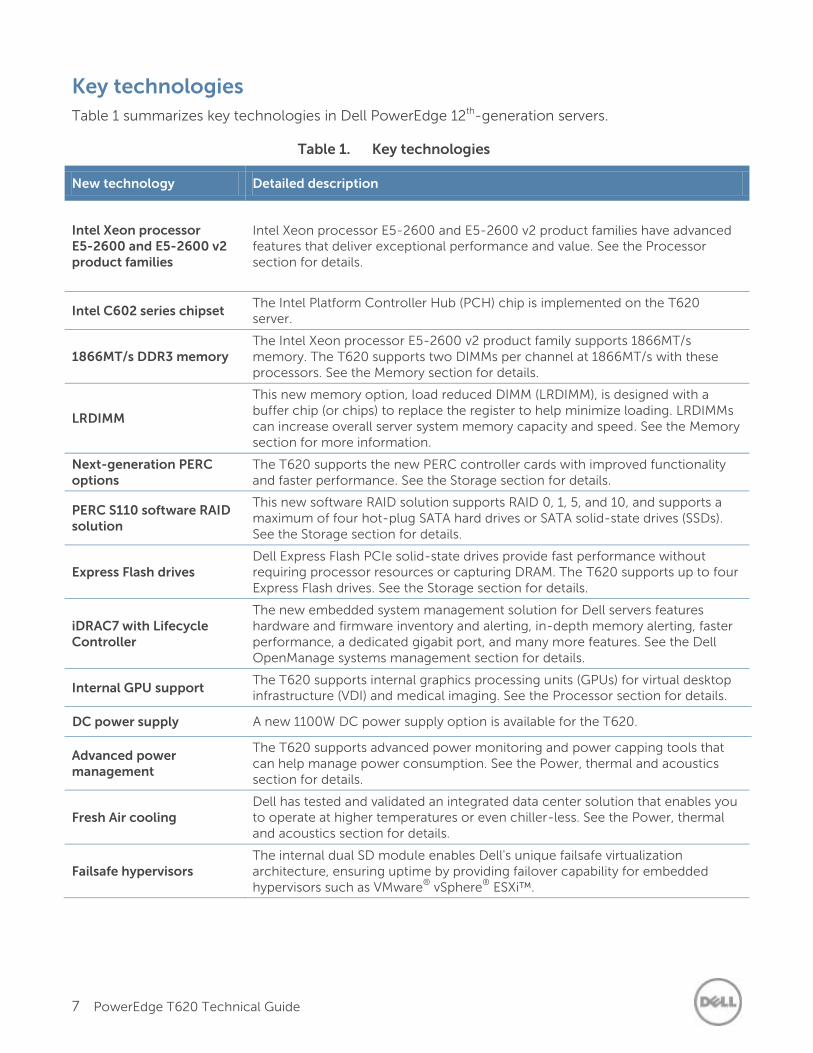
Table 1 summarizes key technologies in Dell PowerEdge 12th-generation servers.
Table 1. Key technologies
New technology Detailed description
Intel Xeon processor E5-2600 and E5-2600 v2 product families
Intel Xeon processor E5-2600 and E5-2600 v2 product families have advanced features that deliver exceptional performance and value. See the Processor section for details.
Intel C602 series chipset The Intel Platform Controller Hub (PCH) chip is implemented on the T620 server.
1866MT/s DDR3 memory The Intel Xeon processor E5-2600 v2 product family supports 1866MT/s memory. The T620 supports two DIMMs per channel at 1866MT/s with these processors. See the Memory section for details.
LRDIMM
This new memory option, load reduced DIMM (LRDIMM), is designed with a buffer chip (or chips) to replace the register to help minimize loading. LRDIMMs can increase overall server system memory capacity and speed. See the Memory section for more information.
Next-generation PERC options
The T620 supports the new PERC controller cards with improved functionality and faster performance. See the Storage section for details.
PERC S110 software RAID solution
This new software RAID solution supports RAID 0, 1, 5, and 10, and supports a maximum of four hot-plug SATA hard drives or SATA solid-state drives (SSDs). See the Storage section for details.
Express Flash drives Dell Express Flash PCIe solid-state drives provide fast performance without requiring processor resources or capturing DRAM. The T620 supports up to four Express Flash drives. See the Storage section for details.
iDRAC7 with Lifecycle Controller
The new embedded system management solution for Dell servers features hardware and firmware inventory and alerting, in-depth memory alerting, faster performance, a dedicated gigabit port, and many more features. See the Dell OpenManage systems management section for details.
Internal GPU support The T620 supports internal graphics processing units (GPUs) for virtual desktop infrastructure (VDI) and medical imaging. See the Processor section for details.
DC power supply A new 1100W DC power supply option is available for the T620.
Advanced power management
The T620 supports advanced power monitoring and power capping tools that can help manage power consumption. See the Power, thermal and acoustics section for details.
Fresh Air cooling Dell has tested and validated an integrated data center solution that enables you to operate at higher temperatures or even chiller-less. See the Power, thermal and acoustics section for details.
Failsafe hypervisors The internal dual SD module enables Dell's unique failsafe virtualization architecture, ensuring uptime by providing failover capability for embedded hypervisors such as VMware
® vSphere
® ESXi™.
8 PowerEdge T620 Technical Guide
2 System features
The Dell PowerEdge T620 can be used to consolidate the workload of multiple smaller or previous-generation servers. In comparison, the Dell PowerEdge T620 offers more disk drive options, more PCIe slots, PCIe 3.0, Express Flash PCIe solid-state drives, a larger memory footprint, and optional internal graphics processing unit (GPU) support.
Comparison of PowerEdge systems
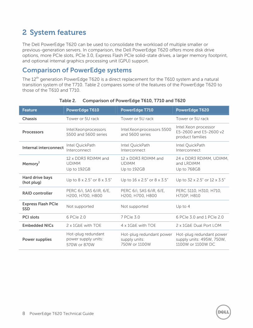
The 12th generation PowerEdge T620 is a direct replacement for the T610 system and a natural transition system of the T710. Table 2 compares some of the features of the PowerEdge T620 to those of the T610 and T710.
Table 2. Comparison of PowerEdge T610, T710 and T620
Feature PowerEdge T610 PowerEdge T710 PowerEdge T620
Chassis Tower or 5U rack Tower or 5U rack Tower or 5U rack
Processors Intel Xeon processors 5500 and 5600 series
Intel Xeon processors 5500 and 5600 series
Intel Xeon processor E5-2600 and E5-2600 v2 product families
Internal interconnect Intel QuickPath Interconnect
Intel QuickPath Interconnect
Intel QuickPath Interconnect
Memory1
12 x DDR3 RDIMM and UDIMM
Up to 192GB
12 x DDR3 RDIMM and UDIMM
Up to 192GB
24 x DDR3 RDIMM, UDIMM, and LRDIMM
Up to 768GB
Hard drive bays (hot plug)
Up to 8 x 2.5” or 8 x 3.5” Up to 16 x 2.5” or 8 x 3.5” Up to 32 x 2.5” or 12 x 3.5”
RAID controller PERC 6/i, SAS 6/iR, 6/E, H200, H700, H800
PERC 6/i, SAS 6/iR, 6/E, H200, H700, H800
PERC S110, H310, H710, H710P, H810
Express Flash PCIe SSD Not supported Not supported Up to 4
PCI slots 6 PCIe 2.0 7 PCIe 3.0 6 PCIe 3.0 and 1 PCIe 2.0
Embedded NICs 2 x 1GbE with TOE 4 x 1GbE with TOE 2 x 1GbE Dual Port LOM
Power supplies
Hot-plug redundant power supply units:
570W or 870W
Hot-plug redundant power supply units: 750W or 1100W
Hot-plug redundant power supply units: 495W, 750W, 1100W or 1100W DC
9 PowerEdge T620 Technical Guide
Feature PowerEdge T610 PowerEdge T710 PowerEdge T620
Dell OpenManage Systems Management
Dell OpenManage
Lifecycle Controller 1.x
iDRAC6 (Express or Enterprise) with
Lifecycle Controller 1.x
Dell OpenManage
Lifecycle Controller 1.x
iDRAC6 (Express or Enterprise) with
Lifecycle Controller 1.x
OpenManage Essentials
OMSA Agent
OpenManage Power Center (requires iDRAC7 Enterprise with Lifecycle Controller)
OpenManage Integrations and Connections
iDRAC7 Express with Lifecycle Controller (standard option)
Internal GPU Not supported Not supported Up to 4 (single width or double width)
Power efficiency Gold Gold Titanium
Availability
Hot-plug drives, optional redundant cooling, hot-plug redundant PSUs, internal dual SD module
Hot-plug drives, hot-plug redundant cooling, hot-plug redundant PSUs, internal dual SD module
Hot-plug drives, hot-plug redundant cooling, hot-plug redundant PSUs, internal dual SD module
1GB means 1 billion bytes and TB equals 1 trillion bytes; actual capacity varies with preloaded material and operating
environment and will be less
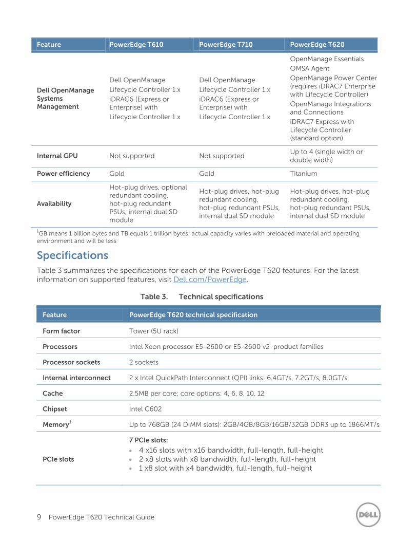
Specifications
Table 3 summarizes the specifications for each of the PowerEdge T620 features. For the latest information on supported features, visit Dell.com/PowerEdge.
Table 3. Technical specifications
Feature PowerEdge T620 technical specification
Form factor Tower (5U rack)
Processors Intel Xeon processor E5-2600 or E5-2600 v2 product families
Processor sockets 2 sockets
Internal interconnect 2 x Intel QuickPath Interconnect (QPI) links: 6.4GT/s, 7.2GT/s, 8.0GT/s
Cache 2.5MB per core; core options: 4, 6, 8, 10, 12
Chipset Intel C602
Memory1 Up to 768GB (24 DIMM slots): 2GB/4GB/8GB/16GB/32GB DDR3 up to 1866MT/s
PCIe slots
7 PCIe slots:
4 x16 slots with x16 bandwidth, full-length, full-height 2 x8 slots with x8 bandwidth, full-length, full-height 1 x8 slot with x4 bandwidth, full-length, full-height
10 PowerEdge T620 Technical Guide
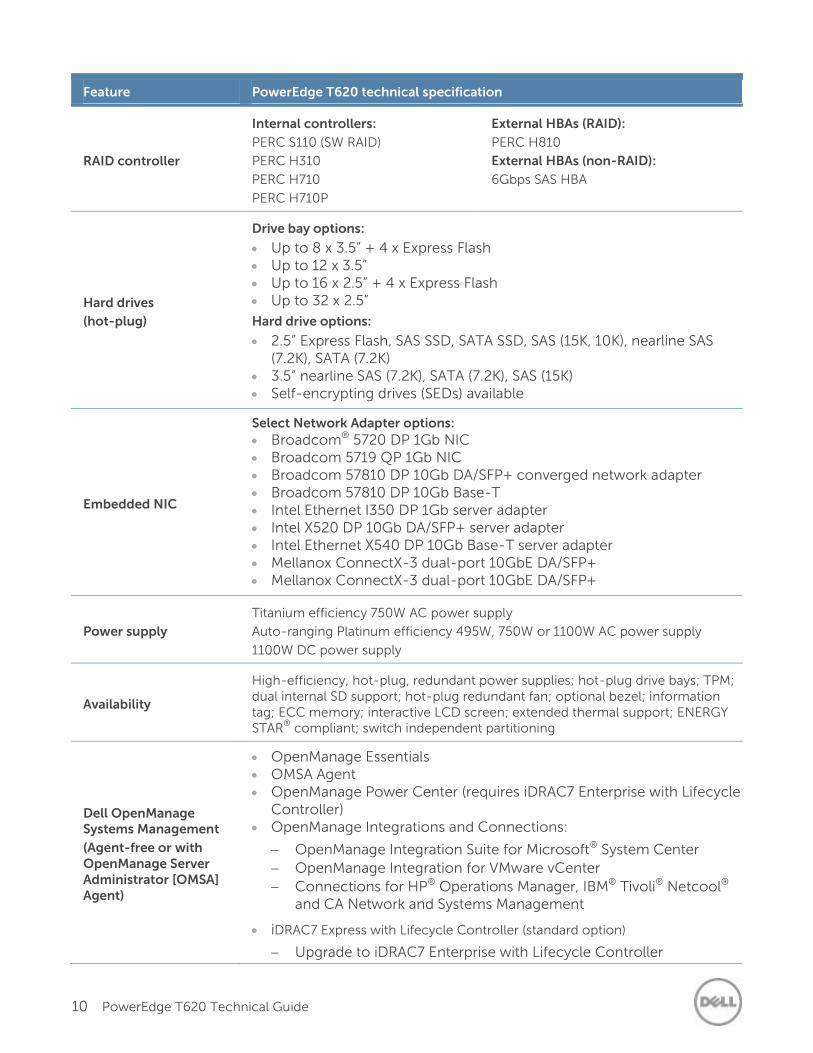
Feature PowerEdge T620 technical specification
RAID controller
Internal controllers:
PERC S110 (SW RAID)
PERC H310
PERC H710
PERC H710P
External HBAs (RAID):
PERC H810
External HBAs (non-RAID):
6Gbps SAS HBA
Hard drives
(hot-plug)
Drive bay options:
Up to 8 x 3.5” + 4 x Express Flash Up to 12 x 3.5” Up to 16 x 2.5” + 4 x Express Flash Up to 32 x 2.5”
Hard drive options:
2.5” Express Flash, SAS SSD, SATA SSD, SAS (15K, 10K), nearline SAS (7.2K), SATA (7.2K)
3.5” nearline SAS (7.2K), SATA (7.2K), SAS (15K) Self-encrypting drives (SEDs) available
Embedded NIC
Select Network Adapter options:
Broadcom® 5720 DP 1Gb NIC Broadcom 5719 QP 1Gb NIC Broadcom 57810 DP 10Gb DA/SFP+ converged network adapter Broadcom 57810 DP 10Gb Base-T Intel Ethernet I350 DP 1Gb server adapter Intel X520 DP 10Gb DA/SFP+ server adapter Intel Ethernet X540 DP 10Gb Base-T server adapter Mellanox ConnectX-3 dual-port 10GbE DA/SFP+ Mellanox ConnectX-3 dual-port 10GbE DA/SFP+
Power supply
Titanium efficiency 750W AC power supply
Auto-ranging Platinum efficiency 495W, 750W or 1100W AC power supply
1100W DC power supply
Availability
High-efficiency, hot-plug, redundant power supplies; hot-plug drive bays; TPM; dual internal SD support; hot-plug redundant fan; optional bezel; information tag; ECC memory; interactive LCD screen; extended thermal support; ENERGY STAR
® compliant; switch independent partitioning
Dell OpenManage Systems Management
(Agent-free or with OpenManage Server Administrator [OMSA] Agent)
OpenManage Essentials OMSA Agent OpenManage Power Center (requires iDRAC7 Enterprise with Lifecycle
Controller) OpenManage Integrations and Connections:
OpenManage Integration Suite for Microsoft® System Center
OpenManage Integration for VMware vCenter
Connections for HP® Operations Manager, IBM® Tivoli® Netcool® and CA Network and Systems Management
iDRAC7 Express with Lifecycle Controller (standard option)
Upgrade to iDRAC7 Enterprise with Lifecycle Controller
11 PowerEdge T620 Technical Guide
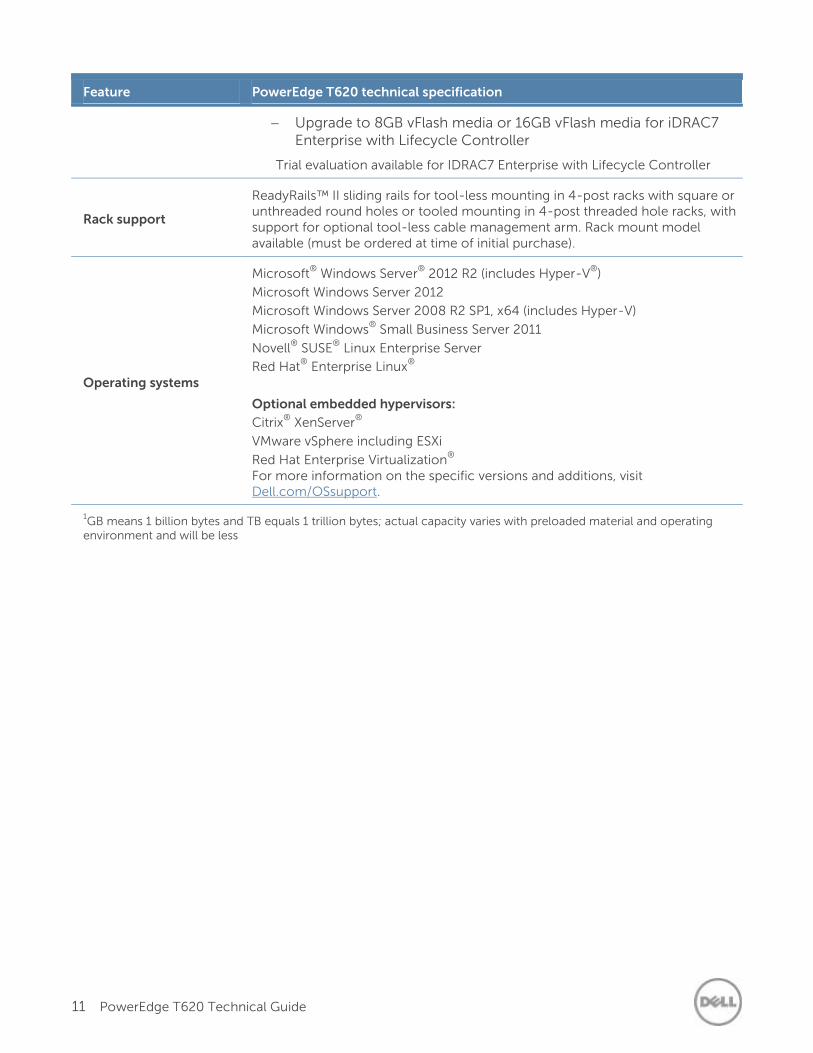
Feature PowerEdge T620 technical specification
Upgrade to 8GB vFlash media or 16GB vFlash media for iDRAC7 Enterprise with Lifecycle Controller
Trial evaluation available for IDRAC7 Enterprise with Lifecycle Controller
Rack support
ReadyRails™ II sliding rails for tool-less mounting in 4-post racks with square or unthreaded round holes or tooled mounting in 4-post threaded hole racks, with support for optional tool-less cable management arm. Rack mount model available (must be ordered at time of initial purchase).
Operating systems
Microsoft®
Windows Server®
2012 R2 (includes Hyper-V®
)
Microsoft Windows Server 2012
Microsoft Windows Server 2008 R2 SP1, x64 (includes Hyper-V)
Microsoft Windows®
Small Business Server 2011
Novell®
SUSE®
Linux Enterprise Server
Red Hat®
Enterprise Linux®
Optional embedded hypervisors:
Citrix®
XenServer®
VMware vSphere including ESXi
Red Hat Enterprise Virtualization®
For more information on the specific versions and additions, visit Dell.com/OSsupport.
1GB means 1 billion bytes and TB equals 1 trillion bytes; actual capacity varies with preloaded material and operating
environment and will be less
12 PowerEdge T620 Technical Guide
3 Chassis views and features
The Dell PowerEdge T620 is a 5U rackable tower server. The T620 provides various storage options including different drive types, internal and external storage controllers, and different chassis options for the various hard drive configurations. Key features for the T620 chassis include:
Updated industrial design including a new LCD panel and bezel (optional security bezel available)
Support for persistent storage through internal USB and SD card slots
Front access for vFlash media reader
Front VGA port for rack-mount chassis
Front LCD panel for rack-mount chassis
Chassis views
The T620 is available in several configuration options, supporting up to 12 3.5-inch hard drives or up to 32 2.5-inch hard drives. All of these options can be selected in a tower or rack configuration at the time of purchase. A system, however, cannot be upgraded, reconfigured, or converted (for example, from tower to rack) after point of purchase. For the latest configuration details, visit Dell.com/PowerEdge. See the Storage section for details about the T620 hot-plug hard drive options.
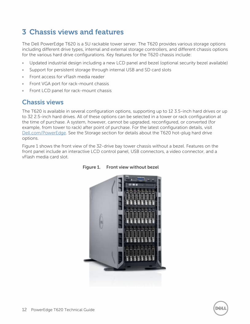
Figure 1 shows the front view of the 32-drive bay tower chassis without a bezel. Features on the front panel include an interactive LCD control panel, USB connectors, a video connector, and a vFlash media card slot.
Figure 1. Front view without bezel
13 PowerEdge T620 Technical Guide
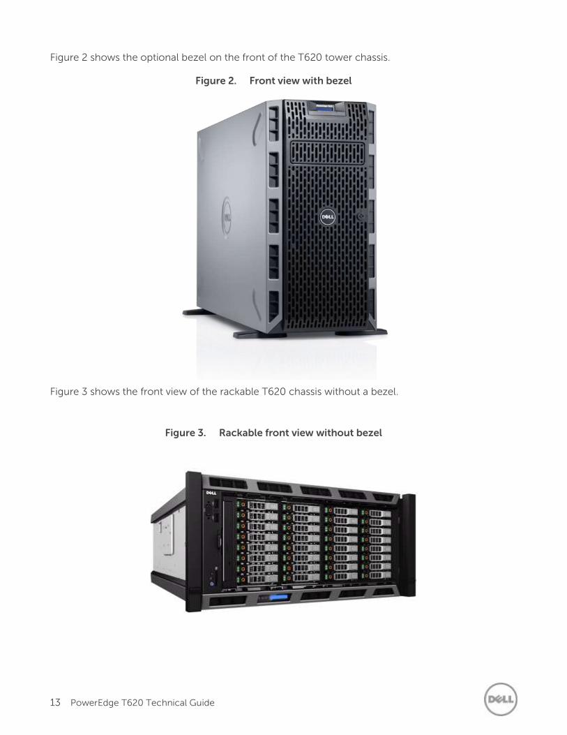
Figure 2 shows the optional bezel on the front of the T620 tower chassis.
Figure 2. Front view with bezel
Figure 3 shows the front view of the rackable T620 chassis without a bezel.
Figure 3. Rackable front view without bezel
14 PowerEdge T620 Technical Guide
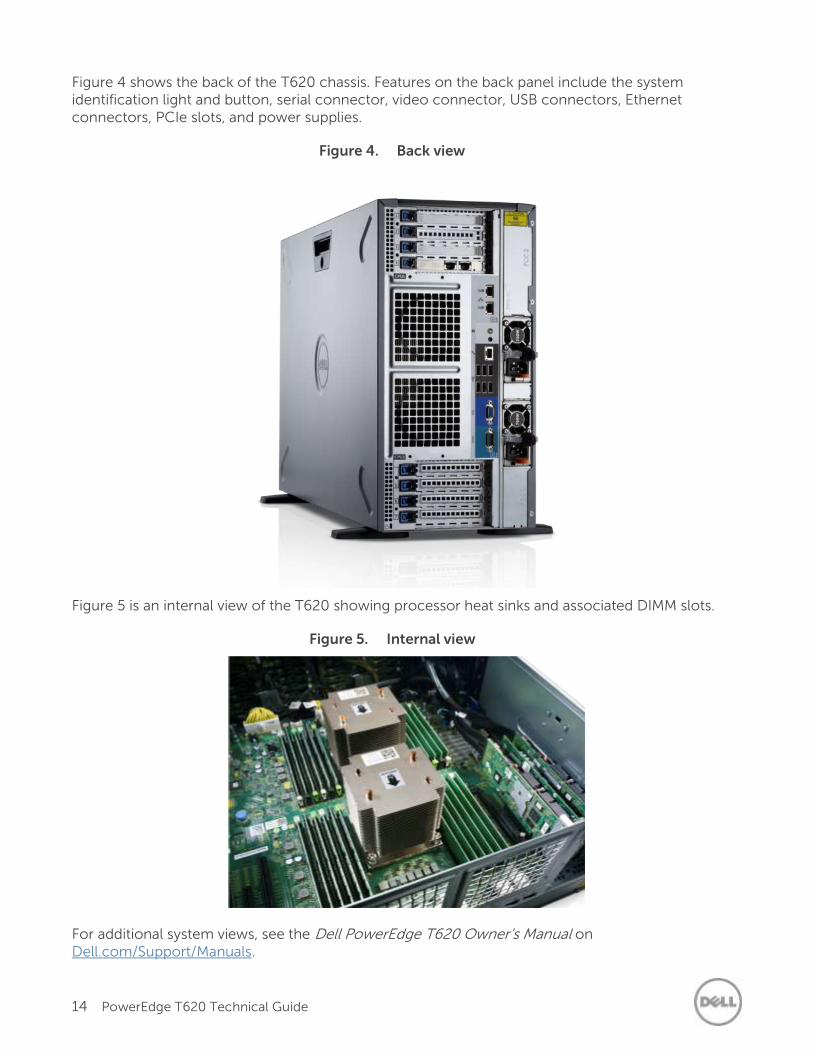
Figure 4 shows the back of the T620 chassis. Features on the back panel include the system identification light and button, serial connector, video connector, USB connectors, Ethernet connectors, PCIe slots, and power supplies.
Figure 4. Back view
Figure 5 is an internal view of the T620 showing processor heat sinks and associated DIMM slots.
Figure 5. Internal view
For additional system views, see the Dell PowerEdge T620 Owner’s Manual on Dell.com/Support/Manuals.
15 PowerEdge T620 Technical Guide
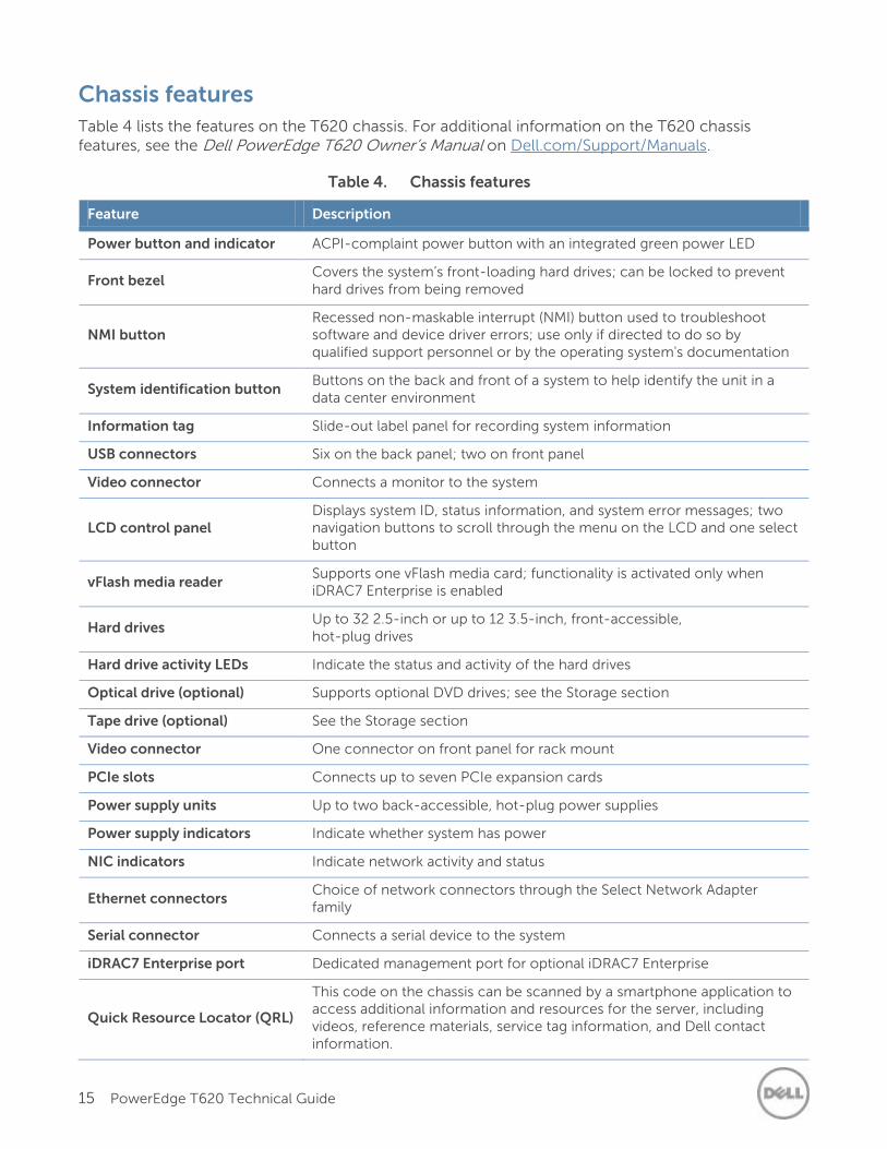
Chassis features
Table 4 lists the features on the T620 chassis. For additional information on the T620 chassis features, see the Dell PowerEdge T620 Owner’s Manual on Dell.com/Support/Manuals.
Table 4. Chassis features
Feature Description
Power button and indicator ACPI-complaint power button with an integrated green power LED
Front bezel Covers the system’s front-loading hard drives; can be locked to prevent hard drives from being removed
NMI button Recessed non-maskable interrupt (NMI) button used to troubleshoot software and device driver errors; use only if directed to do so by qualified support personnel or by the operating system's documentation
System identification button Buttons on the back and front of a system to help identify the unit in a data center environment
Information tag Slide-out label panel for recording system information
USB connectors Six on the back panel; two on front panel
Video connector Connects a monitor to the system
LCD control panel Displays system ID, status information, and system error messages; two navigation buttons to scroll through the menu on the LCD and one select button
vFlash media reader Supports one vFlash media card; functionality is activated only when iDRAC7 Enterprise is enabled
Hard drives Up to 32 2.5-inch or up to 12 3.5-inch, front-accessible, hot-plug drives
Hard drive activity LEDs Indicate the status and activity of the hard drives
Optical drive (optional) Supports optional DVD drives; see the Storage section
Tape drive (optional) See the Storage section
Video connector One connector on front panel for rack mount
PCIe slots Connects up to seven PCIe expansion cards
Power supply units Up to two back-accessible, hot-plug power supplies
Power supply indicators Indicate whether system has power
NIC indicators Indicate network activity and status
Ethernet connectors Choice of network connectors through the Select Network Adapter family
Serial connector Connects a serial device to the system
iDRAC7 Enterprise port Dedicated management port for optional iDRAC7 Enterprise
Quick Resource Locator (QRL)
This code on the chassis can be scanned by a smartphone application to access additional information and resources for the server, including videos, reference materials, service tag information, and Dell contact information.
16 PowerEdge T620 Technical Guide
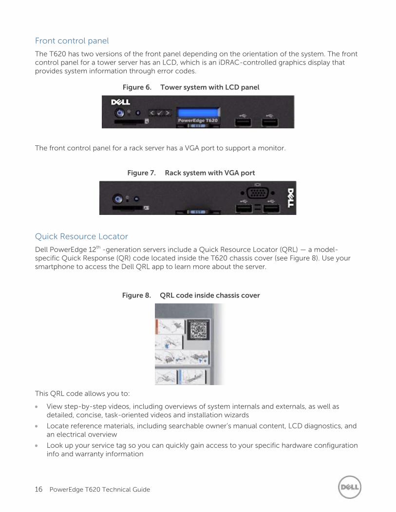
Front control panel
The T620 has two versions of the front panel depending on the orientation of the system. The front control panel for a tower server has an LCD, which is an iDRAC-controlled graphics display that provides system information through error codes.
Figure 6. Tower system with LCD panel
The front control panel for a rack server has a VGA port to support a monitor.
Figure 7. Rack system with VGA port
Quick Resource Locator
Dell PowerEdge 12th -generation servers include a Quick Resource Locator (QRL) — a model-specific Quick Response (QR) code located inside the T620 chassis cover (see Figure 8). Use your smartphone to access the Dell QRL app to learn more about the server.
Figure 8. QRL code inside chassis cover
This QRL code allows you to:
View step-by-step videos, including overviews of system internals and externals, as well as detailed, concise, task-oriented videos and installation wizards
Locate reference materials, including searchable owner’s manual content, LCD diagnostics, and an electrical overview
Look up your service tag so you can quickly gain access to your specific hardware configuration info and warranty information
17 PowerEdge T620 Technical Guide
Contact Dell directly (by link) to get in touch with technical support and sales teams and provide feedback to Dell
These codes provide an easy way to retrieve the critical support information you need when you need it, making you more efficient and effective in managing your hardware.
Security features
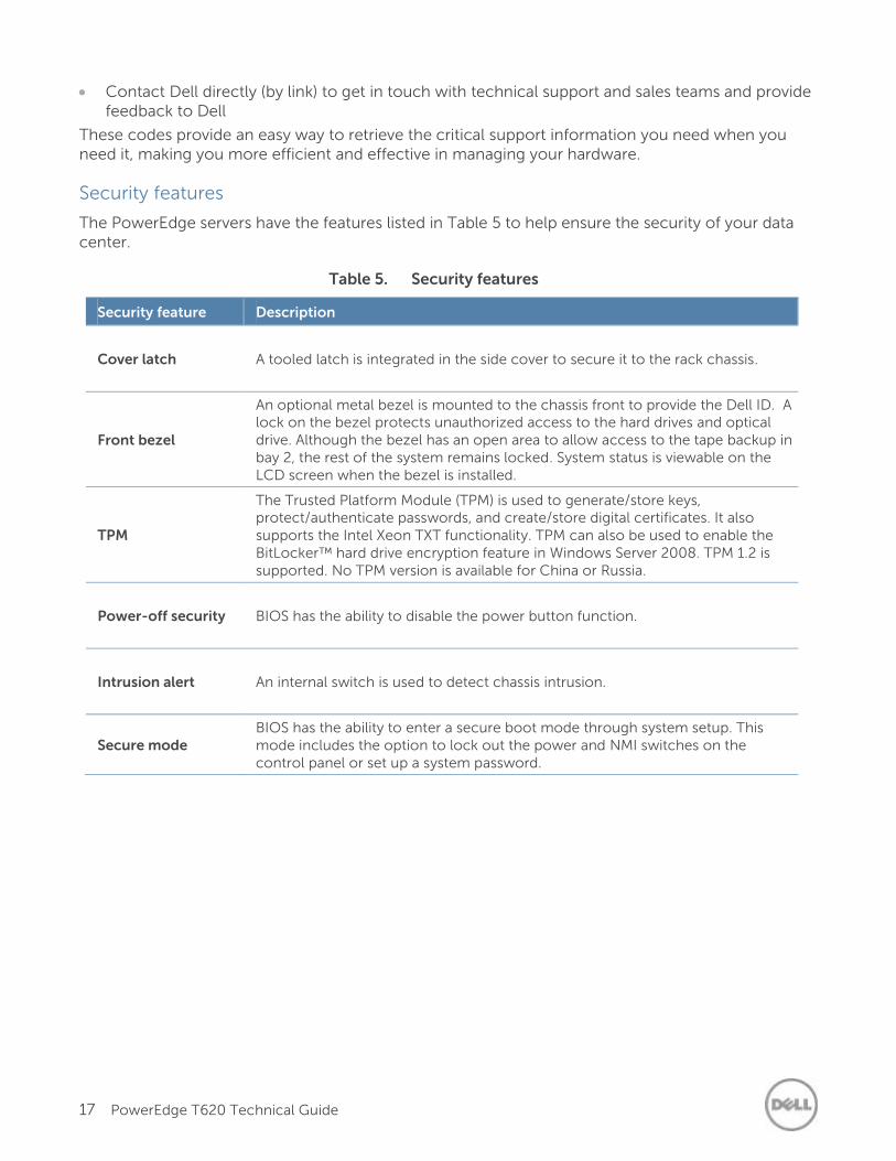
The PowerEdge servers have the features listed in Table 5 to help ensure the security of your data center.
Table 5. Security features
Security feature Description
Cover latch
A tooled latch is integrated in the side cover to secure it to the rack chassis.
Front bezel
An optional metal bezel is mounted to the chassis front to provide the Dell ID. A lock on the bezel protects unauthorized access to the hard drives and optical drive. Although the bezel has an open area to allow access to the tape backup in bay 2, the rest of the system remains locked. System status is viewable on the LCD screen when the bezel is installed.
TPM
The Trusted Platform Module (TPM) is used to generate/store keys, protect/authenticate passwords, and create/store digital certificates. It also supports the Intel Xeon TXT functionality. TPM can also be used to enable the BitLocker™ hard drive encryption feature in Windows Server 2008. TPM 1.2 is supported. No TPM version is available for China or Russia.
Power-off security
BIOS has the ability to disable the power button function.
Intrusion alert
An internal switch is used to detect chassis intrusion.
Secure mode BIOS has the ability to enter a secure boot mode through system setup. This mode includes the option to lock out the power and NMI switches on the control panel or set up a system password.
18 PowerEdge T620 Technical Guide
4 Processor
The Dell PowerEdge T620 features the exceptional performance, value and power efficiency of the Intel Xeon processor E5-2600 v2 product family. With up to 12 cores and 30MB cache, E5-2600 v2 processors have the capacity to deliver performance gains of up to 40% over previous-generation E5-2600 processors. No matter your constraint — floor space, power or budget — E5-2600 v2 processors can help you achieve more computational horsepower, in the same footprint, with better security and power efficiency.
Processor features
The Intel Xeon processor E5-2600 v2 product family has powerful new features and improves upon many of the capabilities of the predecessor Intel Xeon processor E5-2600 series:
With up to four additional cores, 10MB more cache and a 17% increase in memory speeds, E5-2600 v2 processors may boost performance by up to 40% in Dell PowerEdge server platforms
Support for DDR3 1866MT/s memory provides faster connections throughout the system
Up to 24 DIMM slots and support for up to 32GB DIMMs enable memory capacity of 768GB Dell’s exclusive Fault Resilient Memory technology provides a protected memory zone for a hypervisor without consuming half of the total RAM in the system,
In combination with Fault Resilient Memory, E5-2600 v2 processors offer Failsafe Virtualization for unsurpassed industry protection for virtual machines.
Intel Secure Key and Intel OS Guard deliver faster and more secure encryption
Advanced Programmable Interrupt Controller virtualization (APICv) improves virtualization performance by reducing virtual machine (VM) exits, thereby reducing overhead required to service every APIC interrupt
Intel Integrated PCI Express 3.0 provides up to 40 lanes per socket
Intel Turbo Boost Technology 2.0 delivers up to double the boost than the previous-generation turbo technology
Dell Processor Acceleration Technology (DPAT), enabled through the BIOS, minimizes transition duration when the processor functions in turbo mode, thereby decreasing jitter and allowing for lesser latency.
Intel Data Direct I/O (DDIO) allows I/O traffic to skip the main system memory and be directed straight to the processor cache, which can provide a significant reduction in latency as well as allowing memory to remain in a low-power state
Intel Advanced Vector Extensions offer up to double the floating point operations per clock cycle by doubling the length of registers, which can be useful in large-number calculations, integral to many technical, financial and scientific computing problems.
For more information on the Intel Xeon processor E5-2600 product family, visit Intel.com.
19 PowerEdge T620 Technical Guide
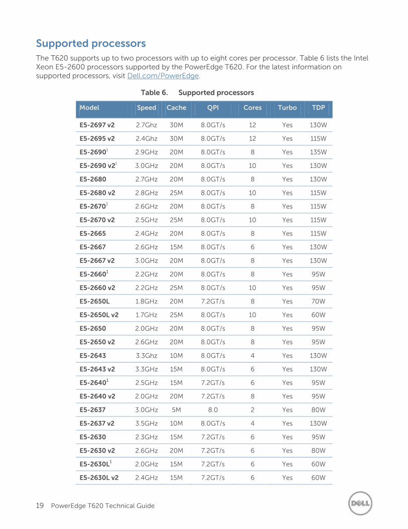
Supported processors
The T620 supports up to two processors with up to eight cores per processor. Table 6 lists the Intel Xeon E5-2600 processors supported by the PowerEdge T620. For the latest information on supported processors, visit Dell.com/PowerEdge.
Table 6. Supported processors
Model Speed Cache QPI Cores Turbo TDP
E5-2697 v2 2.7Ghz 30M 8.0GT/s 12 Yes 130W
E5-2695 v2 2.4Ghz 30M 8.0GT/s 12 Yes 115W
E5-26901 2.9GHz 20M 8.0GT/s 8 Yes 135W
E5-2690 v21 3.0GHz 20M 8.0GT/s 10 Yes 130W
E5-2680 2.7GHz 20M 8.0GT/s 8 Yes 130W
E5-2680 v2 2.8GHz 25M 8.0GT/s 10 Yes 115W
E5-26701 2.6GHz 20M 8.0GT/s 8 Yes 115W
E5-2670 v2 2.5GHz 25M 8.0GT/s 10 Yes 115W
E5-2665 2.4GHz 20M 8.0GT/s 8 Yes 115W
E5-2667 2.6GHz 15M 8.0GT/s 6 Yes 130W
E5-2667 v2 3.0GHz 20M 8.0GT/s 8 Yes 130W
E5-26601 2.2GHz 20M 8.0GT/s 8 Yes 95W
E5-2660 v2 2.2GHz 25M 8.0GT/s 10 Yes 95W
E5-2650L 1.8GHz 20M 7.2GT/s 8 Yes 70W
E5-2650L v2 1.7GHz 25M 8.0GT/s 10 Yes 60W
E5-2650 2.0GHz 20M 8.0GT/s 8 Yes 95W
E5-2650 v2 2.6GHz 20M 8.0GT/s 8 Yes 95W
E5-2643 3.3Ghz 10M 8.0GT/s 4 Yes 130W
E5-2643 v2 3.3GHz 15M 8.0GT/s 6 Yes 130W
E5-26401 2.5GHz 15M 7.2GT/s 6 Yes 95W
E5-2640 v2 2.0GHz 20M 7.2GT/s 8 Yes 95W
E5-2637 3.0GHz 5M 8.0 2 Yes 80W
E5-2637 v2 3.5GHz 10M 8.0GT/s 4 Yes 130W
E5-2630 2.3GHz 15M 7.2GT/s 6 Yes 95W
E5-2630 v2 2.6GHz 20M 7.2GT/s 6 Yes 80W
E5-2630L1 2.0GHz 15M 7.2GT/s 6 Yes 60W
E5-2630L v2 2.4GHz 15M 7.2GT/s 6 Yes 60W
20 PowerEdge T620 Technical Guide
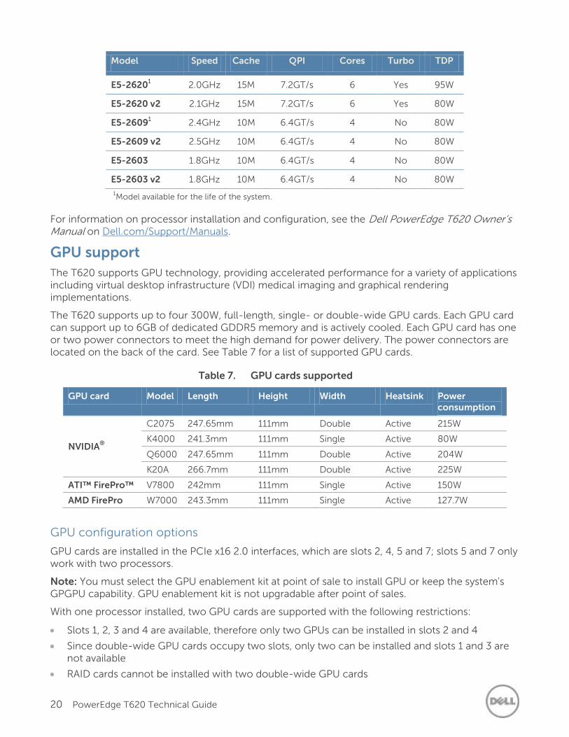
Model Speed Cache QPI Cores Turbo TDP
E5-26201 2.0GHz 15M 7.2GT/s 6 Yes 95W
E5-2620 v2 2.1GHz 15M 7.2GT/s 6 Yes 80W
E5-26091 2.4GHz 10M 6.4GT/s 4 No 80W
E5-2609 v2 2.5GHz 10M 6.4GT/s 4 No 80W
E5-2603 1.8GHz 10M 6.4GT/s 4 No 80W
E5-2603 v2 1.8GHz 10M 6.4GT/s 4 No 80W
1Model available for the life of the system.
For information on processor installation and configuration, see the Dell PowerEdge T620 Owner’s Manual on Dell.com/Support/Manuals.
GPU support
The T620 supports GPU technology, providing accelerated performance for a variety of applications including virtual desktop infrastructure (VDI) medical imaging and graphical rendering implementations.
The T620 supports up to four 300W, full-length, single- or double-wide GPU cards. Each GPU card can support up to 6GB of dedicated GDDR5 memory and is actively cooled. Each GPU card has one or two power connectors to meet the high demand for power delivery. The power connectors are located on the back of the card. See Table 7 for a list of supported GPU cards.
Table 7. GPU cards supported
GPU card Model Length Height Width Heatsink Power consumption
NVIDIA®
C2075 247.65mm 111mm Double Active 215W
K4000 241.3mm 111mm Single Active 80W
Q6000 247.65mm 111mm Double Active 204W
K20A 266.7mm 111mm Double Active 225W
ATI™ FirePro™ V7800 242mm 111mm Single Active 150W
AMD FirePro W7000 243.3mm 111mm Single Active 127.7W
GPU configuration options
GPU cards are installed in the PCIe x16 2.0 interfaces, which are slots 2, 4, 5 and 7; slots 5 and 7 only work with two processors.
Note: You must select the GPU enablement kit at point of sale to install GPU or keep the system's GPGPU capability. GPU enablement kit is not upgradable after point of sales.
With one processor installed, two GPU cards are supported with the following restrictions:
Slots 1, 2, 3 and 4 are available, therefore only two GPUs can be installed in slots 2 and 4
Since double-wide GPU cards occupy two slots, only two can be installed and slots 1 and 3 are not available
RAID cards cannot be installed with two double-wide GPU cards
21 PowerEdge T620 Technical Guide
With single-wide GPU cards, the PERC H710, H710P, or H810 cannot occupy slots 1 or 3 (PERC cards have batteries that would overheat if located beside a GPU card)
With two processors installed, four GPU cards are supported, with the restrictions:
Slots 2, 4, 5, and 7 are available
Since double-wide GPU cards occupy two slots, slots 1, 3, and 6 are not available
RAID cards cannot be installed with four double-wide GPU cards
With single-wide GPU cards, the PERC H710, H710P, or H810 cannot occupy slots 1, 3, or 6 (PERCs have batteries that would overheat if located beside a GPU card)
With PCIe SSDs, two GPU cards can occupy slots 5 and 7. Slot 2 is for a PCIe SSD expender card and slot 4 cannot support a GPU card because of thermal restrictions.
Operating system support for GPUs
Some operating systems have not been validated to support GPUs. See Table 23 and Table 24 for more information on operating system support of GPUs.
Chipset
The Intel C602 chipset is implemented on the PowerEdge T620. For more information, visit Intel.com.
22 PowerEdge T620 Technical Guide
5 Memory
More memory options are available than ever before with the Dell PowerEdge T620 — greater capacities, higher frequencies,= and more flexibility. The T620 supports up to 768GB of memory (24 DIMMs) and speeds up to 1866MT/s, providing high performance in a variety of applications. And, high memory density means no compromise when it comes to virtualization.
Dell’s focus on reliability, availability and serviceability (RAS) features can help you increase your uptime and reduce data loss. RAS aids in the rapid and accurate diagnosis of faults which require service, increasing your memory reliability. System uptime is reinforced with RAS features like memory mirroring, sparing and many others.
In addition to supporting existing unbuffered DIMMs (UDIMMs) and registered DIMMs (RDIMMs), the T620 supports load reduced DIMMs (LRDIMMs), which use a buffer to reduce memory loading and provide greater density, allowing for the maximum platform memory capacity.
Supported memory
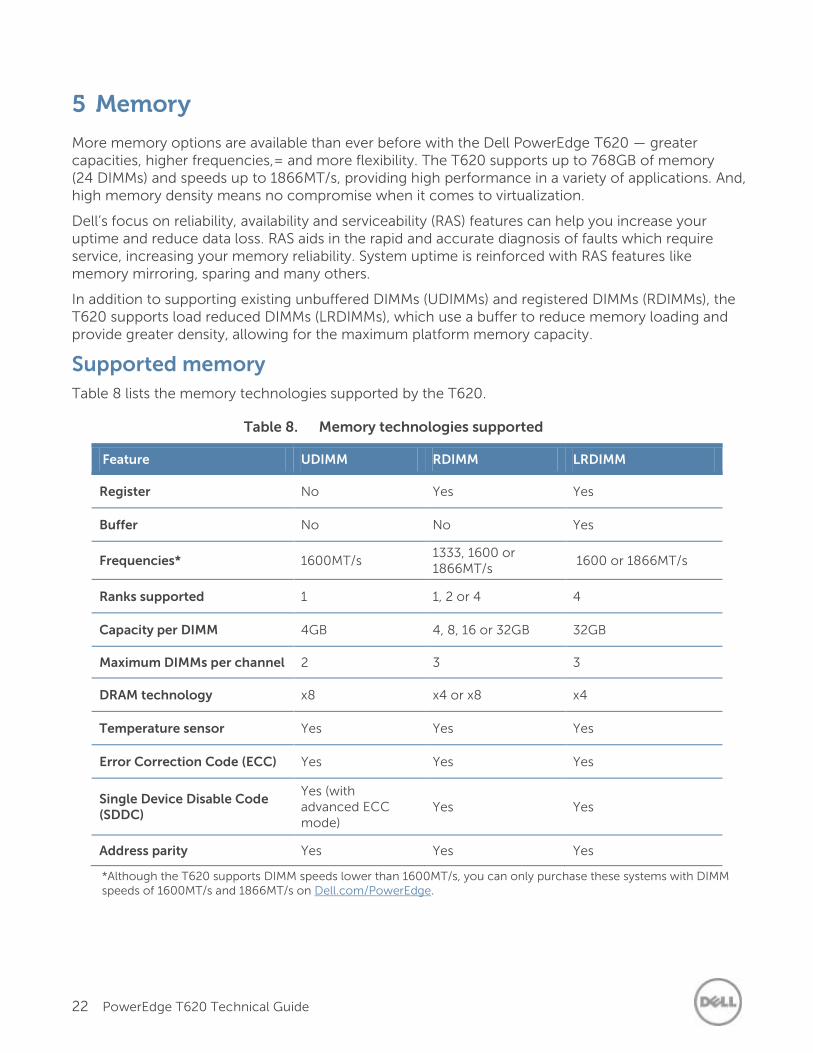
Table 8 lists the memory technologies supported by the T620.
Table 8. Memory technologies supported
Feature UDIMM RDIMM LRDIMM
Register No Yes Yes
Buffer No No Yes
Frequencies* 1600MT/s 1333, 1600 or 1866MT/s
1600 or 1866MT/s
Ranks supported 1 1, 2 or 4 4
Capacity per DIMM 4GB 4, 8, 16 or 32GB 32GB
Maximum DIMMs per channel 2 3 3
DRAM technology x8 x4 or x8 x4
Temperature sensor Yes Yes Yes
Error Correction Code (ECC) Yes Yes Yes
Single Device Disable Code (SDDC)
Yes (with advanced ECC mode)
Yes Yes
Address parity Yes Yes Yes
*Although the T620 supports DIMM speeds lower than 1600MT/s, you can only purchase these systems with DIMM speeds of 1600MT/s and 1866MT/s on Dell.com/PowerEdge.
23 PowerEdge T620 Technical Guide
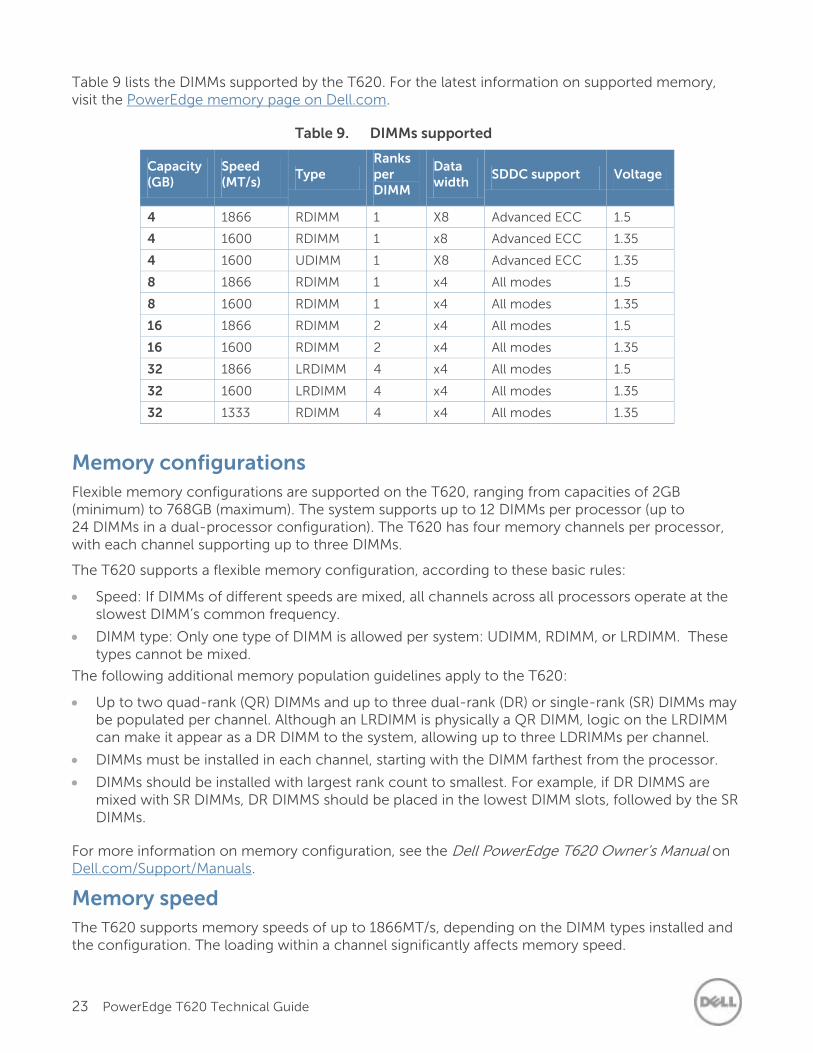
Table 9 lists the DIMMs supported by the T620. For the latest information on supported memory, visit the PowerEdge memory page on Dell.com.
Table 9. DIMMs supported
Capacity (GB)
Speed (MT/s)
Type Ranks per DIMM
Data width
SDDC support Voltage
4 1866 RDIMM 1 X8 Advanced ECC 1.5
4 1600 RDIMM 1 x8 Advanced ECC 1.35
4 1600 UDIMM 1 X8 Advanced ECC 1.35
8 1866 RDIMM 1 x4 All modes 1.5
8 1600 RDIMM 1 x4 All modes 1.35
16 1866 RDIMM 2 x4 All modes 1.5
16 1600 RDIMM 2 x4 All modes 1.35
32 1866 LRDIMM 4 x4 All modes 1.5
32 1600 LRDIMM 4 x4 All modes 1.35
32 1333 RDIMM 4 x4 All modes 1.35
Memory configurations
Flexible memory configurations are supported on the T620, ranging from capacities of 2GB (minimum) to 768GB (maximum). The system supports up to 12 DIMMs per processor (up to 24 DIMMs in a dual-processor configuration). The T620 has four memory channels per processor, with each channel supporting up to three DIMMs.
The T620 supports a flexible memory configuration, according to these basic rules:
Speed: If DIMMs of different speeds are mixed, all channels across all processors operate at the slowest DIMM’s common frequency.
DIMM type: Only one type of DIMM is allowed per system: UDIMM, RDIMM, or LRDIMM. These types cannot be mixed.
The following additional memory population guidelines apply to the T620:
Up to two quad-rank (QR) DIMMs and up to three dual-rank (DR) or single-rank (SR) DIMMs may be populated per channel. Although an LRDIMM is physically a QR DIMM, logic on the LRDIMM can make it appear as a DR DIMM to the system, allowing up to three LDRIMMs per channel.
DIMMs must be installed in each channel, starting with the DIMM farthest from the processor.
DIMMs should be installed with largest rank count to smallest. For example, if DR DIMMS are mixed with SR DIMMs, DR DIMMS should be placed in the lowest DIMM slots, followed by the SR DIMMs.
For more information on memory configuration, see the Dell PowerEdge T620 Owner’s Manual on Dell.com/Support/Manuals.
Memory speed
The T620 supports memory speeds of up to 1866MT/s, depending on the DIMM types installed and the configuration. The loading within a channel significantly affects memory speed.
24 PowerEdge T620 Technical Guide
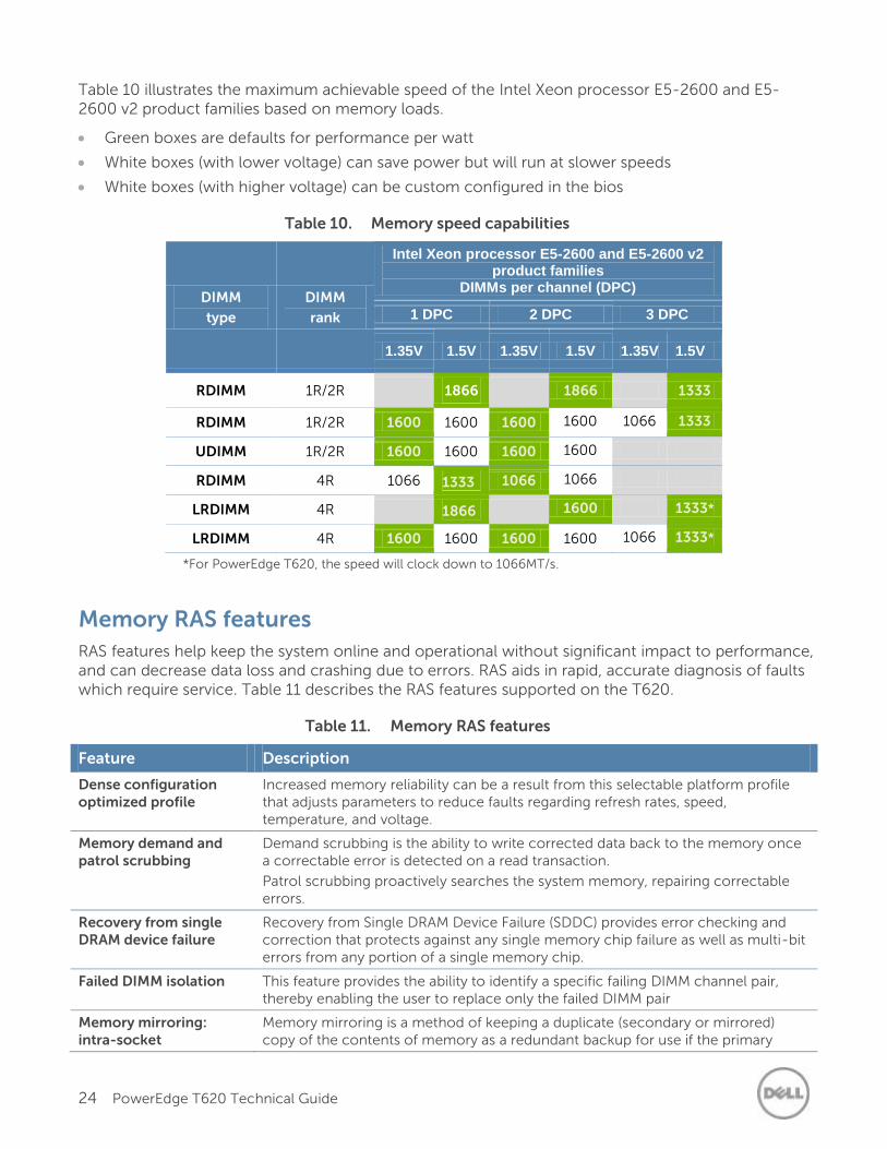
Table 10 illustrates the maximum achievable speed of the Intel Xeon processor E5-2600 and E5-2600 v2 product families based on memory loads.
Green boxes are defaults for performance per watt
White boxes (with lower voltage) can save power but will run at slower speeds
White boxes (with higher voltage) can be custom configured in the bios
Table 10. Memory speed capabilities
DIMM
type
DIMM
rank
Intel Xeon processor E5-2600 and E5-2600 v2 product families
DIMMs per channel (DPC)
1 DPC 2 DPC 3 DPC
1.35V 1.5V 1.35V 1.5V 1.35V 1.5V
RDIMM 1R/2R
1866
1866 1333
RDIMM 1R/2R 1600 1600 1600 1600 1066 1333
UDIMM 1R/2R 1600 1600 1600 1600
RDIMM 4R 1066 1333 1066 1066
LRDIMM 4R 1866
1600 1333*
LRDIMM 4R 1600 1600 1600 1600 1066 1333*
*For PowerEdge T620, the speed will clock down to 1066MT/s.
Memory RAS features
RAS features help keep the system online and operational without significant impact to performance, and can decrease data loss and crashing due to errors. RAS aids in rapid, accurate diagnosis of faults which require service. Table 11 describes the RAS features supported on the T620.
Table 11. Memory RAS features
Feature Description
Dense configuration optimized profile
Increased memory reliability can be a result from this selectable platform profile that adjusts parameters to reduce faults regarding refresh rates, speed, temperature, and voltage.
Memory demand and patrol scrubbing
Demand scrubbing is the ability to write corrected data back to the memory once a correctable error is detected on a read transaction.
Patrol scrubbing proactively searches the system memory, repairing correctable errors.
Recovery from single DRAM device failure
Recovery from Single DRAM Device Failure (SDDC) provides error checking and correction that protects against any single memory chip failure as well as multi-bit errors from any portion of a single memory chip.
Failed DIMM isolation This feature provides the ability to identify a specific failing DIMM channel pair, thereby enabling the user to replace only the failed DIMM pair
Memory mirroring: intra-socket
Memory mirroring is a method of keeping a duplicate (secondary or mirrored) copy of the contents of memory as a redundant backup for use if the primary
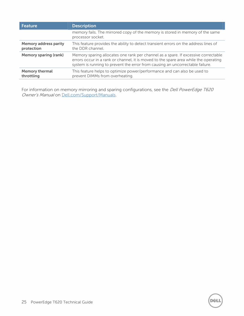
25 PowerEdge T620 Technical Guide
Feature Description
memory fails. The mirrored copy of the memory is stored in memory of the same processor socket.
Memory address parity protection
This feature provides the ability to detect transient errors on the address lines of the DDR channel.
Memory sparing (rank) Memory sparing allocates one rank per channel as a spare. If excessive correctable errors occur in a rank or channel, it is moved to the spare area while the operating system is running to prevent the error from causing an uncorrectable failure.
Memory thermal throttling
This feature helps to optimize power/performance and can also be used to prevent DIMMs from overheating.
For information on memory mirroring and sparing configurations, see the Dell PowerEdge T620 Owner’s Manual on Dell.com/Support/Manuals.
26 PowerEdge T620 Technical Guide
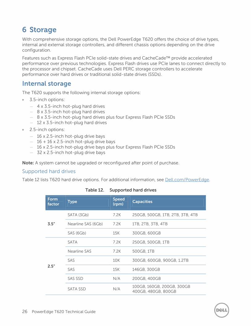
6 Storage With comprehensive storage options, the Dell PowerEdge T620 offers the choice of drive types, internal and external storage controllers, and different chassis options depending on the drive configuration.
Features such as Express Flash PCIe solid-state drives and CacheCade™ provide accelerated performance over previous technologies. Express Flash drives use PCIe lanes to connect directly to the processor and chipset. CacheCade uses Dell PERC storage controllers to accelerate performance over hard drives or traditional solid-state drives (SSDs).
Internal storage
The T620 supports the following internal storage options:
3.5-inch options:
— 4 x 3.5-inch hot-plug hard drives — 8 x 3.5-inch hot-plug hard drives — 8 x 3.5-inch hot-plug hard drives plus four Express Flash PCIe SSDs — 12 x 3.5-inch hot-plug hard drives
2.5-inch options:
— 16 x 2.5-inch hot-plug drive bays — 16 + 16 x 2.5-inch hot-plug drive bays — 16 x 2.5-inch hot-plug drive bays plus four Express Flash PCIe SSDs — 32 x 2.5-inch hot-plug drive bays
Note: A system cannot be upgraded or reconfigured after point of purchase.
Supported hard drives
Table 12 lists T620 hard drive options. For additional information, see Dell.com/PowerEdge.
Table 12. Supported hard drives
Form factor
Type Speed (rpm)
Capacities
3.5”
SATA (3Gb) 7.2K 250GB, 500GB, 1TB, 2TB, 3TB, 4TB
Nearline SAS (6Gb) 7.2K 1TB, 2TB, 3TB, 4TB
SAS (6Gb) 15K 300GB, 600GB
2.5”
SATA 7.2K 250GB, 500GB, 1TB
Nearline SAS 7.2K 500GB, 1TB
SAS 10K 300GB, 600GB, 900GB, 1.2TB
SAS 15K 146GB, 300GB
SAS SSD N/A 200GB, 400GB
SATA SSD N/A 100GB, 160GB, 200GB, 300GB 400GB, 480GB, 800GB
27 PowerEdge T620 Technical Guide
Form factor
Type Speed (rpm)
Capacities
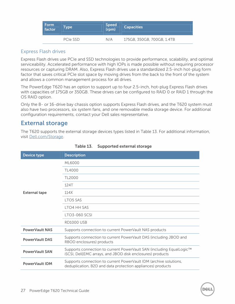
PCIe SSD N/A 175GB, 350GB, 700GB, 1.4TB
Express Flash drives
Express Flash drives use PCIe and SSD technologies to provide performance, scalability, and optimal serviceability. Accelerated performance with high IOPs is made possible without requiring processor resources or capturing DRAM. Also, Express Flash drives use a standardized 2.5-inch hot-plug form factor that saves critical PCIe slot space by moving drives from the back to the front of the system and allows a common management process for all drives.
The PowerEdge T620 has an option to support up to four 2.5-inch, hot-plug Express Flash drives with capacities of 175GB or 350GB. These drives can be configured to RAID 0 or RAID 1 through the OS RAID option.
Only the 8- or 16-drive bay chassis option supports Express Flash drives, and the T620 system must also have two processors, six system fans, and one removable media storage device. For additional configuration requirements, contact your Dell sales representative.
External storage
The T620 supports the external storage devices types listed in Table 13. For additional information, visit Dell.com/Storage.
Table 13. Supported external storage
Device type Description
External tape
ML6000
TL4000
TL2000
124T
114X
LTO5 SAS
LTO4 HH SAS
LTO3-060 SCSI
RD1000 USB
PowerVault NAS Supports connection to current PowerVault NAS products
PowerVault DAS Supports connection to current PowerVault DAS (including JBOD and RBOD enclosures) products
PowerVault SAN Supports connection to current PowerVault SAN (including EqualLogic™ iSCSI, Dell|EMC arrays, and JBOD disk enclosures) products
PowerVault IDM Supports connection to current PowerVault IDM (archive solutions, deduplication, B2D and data protection appliances) products
28 PowerEdge T620 Technical Guide
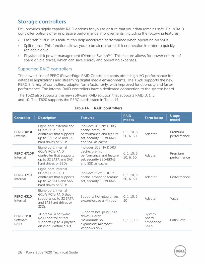
Storage controllers
Dell provides highly capable RAID options for you to ensure that your data remains safe. Dell’s RAID controller options offer impressive performance improvements, including the following features:
FastPath™ I/O: This feature can help accelerate performance when operating on SSDs.
Split mirror: This function allows you to break mirrored disk connection in order to quickly replace a drive.
Physical disk power management (Dimmer Switch™): This feature allows for power control of spare or idle drives, which can save energy and operating expenses.
Supported RAID controllers
The newest line of PERC (PowerEdge RAID Controller) cards offers high I/O performance for database applications and streaming digital media environments. The T620 supports the new PERC 8 family of controllers, adapter form factor only, with improved functionality and faster performance. The internal RAID controllers have a dedicated connection to the system board.
The T620 also supports the new software RAID solution that supports RAID 0, 1, 5, and 10. The T620 supports the PERC cards listed in Table 14.
Table 14. RAID controllers
Controller Description Features RAID modes
Form factor Usage model
PERC H810 External
Eight-port, external and 6Gp/s PCIe RAID controller that supports up to 192 SATA and SAS hard drives or SSDs
Includes 1GB NV DDR3 cache, premium performance and feature set, security SED/EKMS, and SSD as cache
0, 1, 10, 5, 50, 6, 60
Adapter Premium performance
PERC H710P Internal
Eight-port, internal 6Gb/s PCIe RAID controller that supports up to 32 SATA and SAS hard drives or SSDs
Includes 1GB NV DDR3 cache, premium performance and feature set, security SED/EKMS, and SSD as cache
0, 1, 10, 5, 50, 6, 60
Adapter Premium performance
PERC H710 Internal
Eight-port, internal 6Gb/s PCIe RAID controller that supports up to 32 SATA and SAS hard drives or SSDs
Includes 512MB DDR3 cache, advanced feature set, security SED/EKMS
0, 1, 10, 5, 50, 6, 60
Adapter Performance
PERC H310 Internal
Eight-port, internal 6Gb/s PCIe RAID that supports up to 32 SATA and SAS hard drives or SSDs
Supports hot-plug drives, expansion, pass-through
0, 1, 10, 5, 50
Adapter Value
PERC S110 Software RAID
3Gb/s SATA software RAID controller that supports up to 4 physical disks or 8 virtual disks
Supports hot-plug SATA drives (4 drive maximum); no expansion; Microsoft Windows only
0, 1, 5, 10
System board-embedded SATA
Entry-level
29 PowerEdge T620 Technical Guide
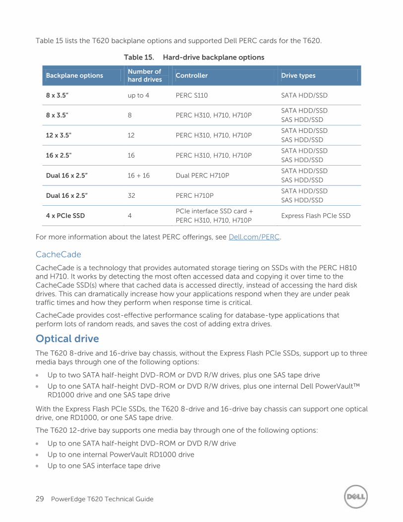
Table 15 lists the T620 backplane options and supported Dell PERC cards for the T620.
Table 15. Hard-drive backplane options
Backplane options Number of hard drives
Controller Drive types
8 x 3.5” up to 4 PERC S110 SATA HDD/SSD
8 x 3.5" 8 PERC H310, H710, H710P SATA HDD/SSD
SAS HDD/SSD
12 x 3.5" 12 PERC H310, H710, H710P SATA HDD/SSD
SAS HDD/SSD
16 x 2.5" 16 PERC H310, H710, H710P SATA HDD/SSD
SAS HDD/SSD
Dual 16 x 2.5” 16 + 16 Dual PERC H710P SATA HDD/SSD
SAS HDD/SSD
Dual 16 x 2.5” 32 PERC H710P SATA HDD/SSD
SAS HDD/SSD
4 x PCIe SSD 4 PCIe interface SSD card +
PERC H310, H710, H710P Express Flash PCIe SSD
For more information about the latest PERC offerings, see Dell.com/PERC.
CacheCade
CacheCade is a technology that provides automated storage tiering on SSDs with the PERC H810 and H710. It works by detecting the most often accessed data and copying it over time to the CacheCade SSD(s) where that cached data is accessed directly, instead of accessing the hard disk drives. This can dramatically increase how your applications respond when they are under peak traffic times and how they perform when response time is critical.
CacheCade provides cost-effective performance scaling for database-type applications that perform lots of random reads, and saves the cost of adding extra drives.
Optical drive
The T620 8-drive and 16-drive bay chassis, without the Express Flash PCIe SSDs, support up to three media bays through one of the following options:
Up to two SATA half-height DVD-ROM or DVD R/W drives, plus one SAS tape drive
Up to one SATA half-height DVD-ROM or DVD R/W drives, plus one internal Dell PowerVault™ RD1000 drive and one SAS tape drive
With the Express Flash PCIe SSDs, the T620 8-drive and 16-drive bay chassis can support one optical drive, one RD1000, or one SAS tape drive.
The T620 12-drive bay supports one media bay through one of the following options:
Up to one SATA half-height DVD-ROM or DVD R/W drive
Up to one internal PowerVault RD1000 drive
Up to one SAS interface tape drive
30 PowerEdge T620 Technical Guide
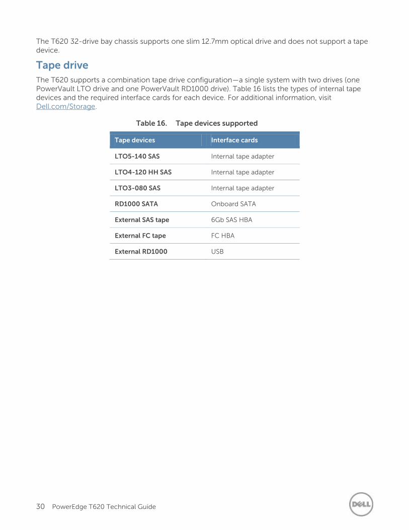
The T620 32-drive bay chassis supports one slim 12.7mm optical drive and does not support a tape device.
Tape drive
The T620 supports a combination tape drive configuration—a single system with two drives (one PowerVault LTO drive and one PowerVault RD1000 drive). Table 16 lists the types of internal tape devices and the required interface cards for each device. For additional information, visit Dell.com/Storage.
Table 16. Tape devices supported
Tape devices Interface cards
LTO5-140 SAS Internal tape adapter
LTO4-120 HH SAS Internal tape adapter
LTO3-080 SAS Internal tape adapter
RD1000 SATA Onboard SATA
External SAS tape 6Gb SAS HBA
External FC tape FC HBA
External RD1000 USB
31 PowerEdge T620 Technical Guide
7 Networking and PCIe
The Dell PowerEdge T620 offers balanced, scalable I/O capabilities, including six integrated PCIe 3.0-capable expansion slots and one dedicated storage controller slot. Networking options for the T620 allow you to tailor your network throughput to match your application needs, enabling added I/O performance.
Embedded NIC controller
The T620 system board has one embedded NIC controller. The Dual Port Intel GbE controller I350-AM2 has the following features:
PCIe 2.0 (5.0GT/s)
Energy Efficient Ethernet (EEE)
RoHS, Halogen free
PCIe expansion
For information on card installation, card requirements, and slot priorities, see the Dell PowerEdge T620 Owner’s Manual on Dell.com/Support/Manuals.
PCIe slots
PCIe connectivity is integrated with the processor, and the number of processors in a system impacts the number of PCIe slots and the bandwidth of each PCIe slot. The PowerEdge T620 offers seven PCIe slots. For a T620 system with one processor, slots 1 through 4 are available. For a T620 system with two processors, all slots are available.
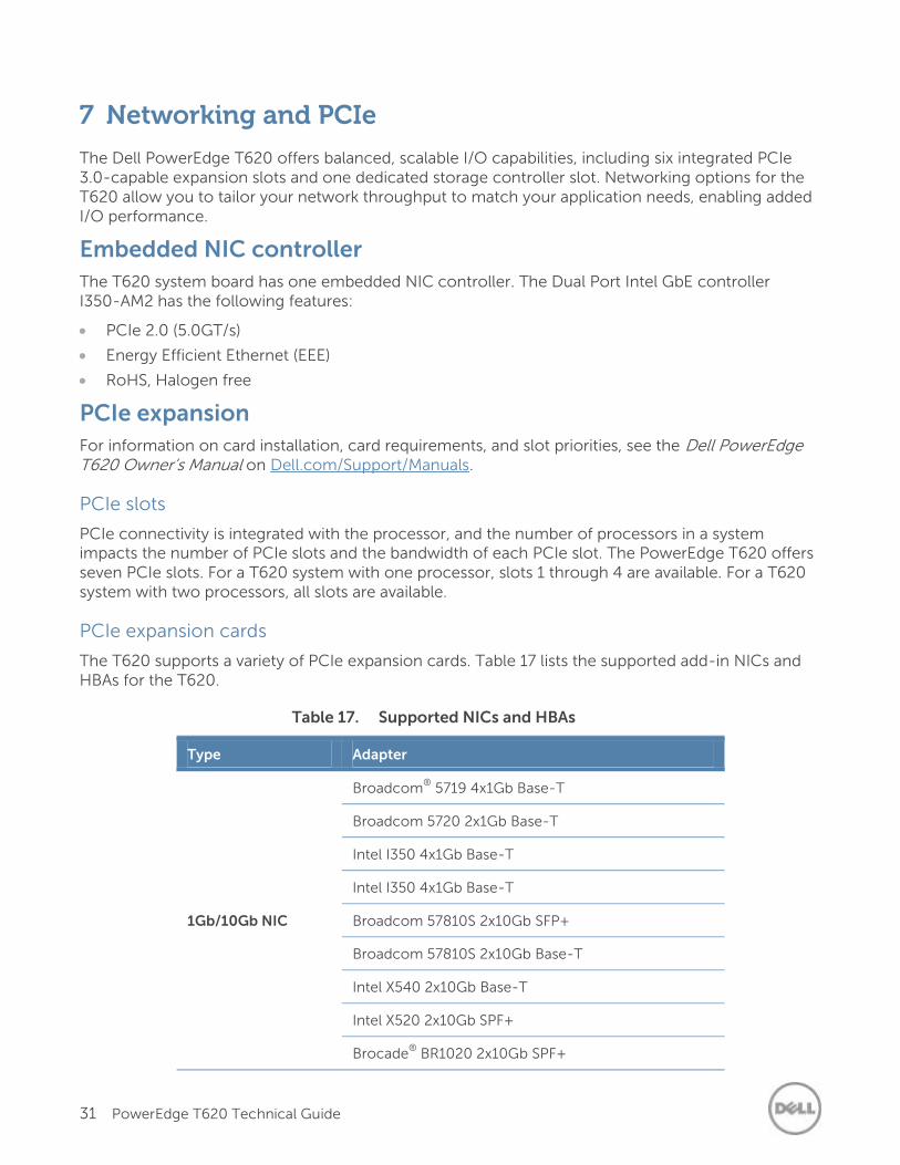
PCIe expansion cards
The T620 supports a variety of PCIe expansion cards. Table 17 lists the supported add-in NICs and HBAs for the T620.
Table 17. Supported NICs and HBAs
Type Adapter
1Gb/10Gb NIC
Broadcom®
5719 4x1Gb Base-T
Broadcom 5720 2x1Gb Base-T
Intel I350 4x1Gb Base-T
Intel I350 4x1Gb Base-T
Broadcom 57810S 2x10Gb SFP+
Broadcom 57810S 2x10Gb Base-T
Intel X540 2x10Gb Base-T
Intel X520 2x10Gb SPF+
Brocade®
BR1020 2x10Gb SPF+
32 PowerEdge T620 Technical Guide
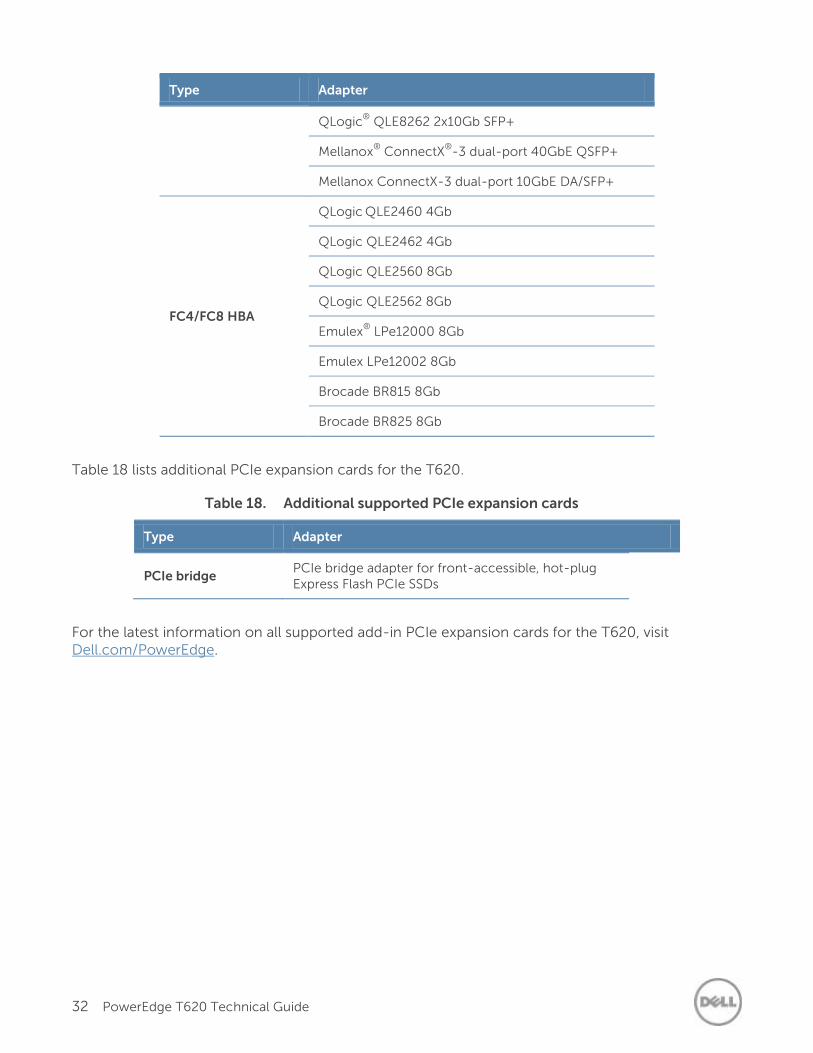
Type Adapter
QLogic®
QLE8262 2x10Gb SFP+
Mellanox®
ConnectX®
-3 dual-port 40GbE QSFP+
Mellanox ConnectX-3 dual-port 10GbE DA/SFP+
FC4/FC8 HBA
QLogic QLE2460 4Gb
QLogic QLE2462 4Gb
QLogic QLE2560 8Gb
QLogic QLE2562 8Gb
Emulex®
LPe12000 8Gb
Emulex LPe12002 8Gb
Brocade BR815 8Gb
Brocade BR825 8Gb
Table 18 lists additional PCIe expansion cards for the T620.
Table 18. Additional supported PCIe expansion cards
Type Adapter
PCIe bridge PCIe bridge adapter for front-accessible, hot-plug Express Flash PCIe SSDs
For the latest information on all supported add-in PCIe expansion cards for the T620, visit Dell.com/PowerEdge.
33 PowerEdge T620 Technical Guide
8 Power, thermal and acoustics
Lower overall system-level power draw is a result of Dell’s breakthrough system design. PowerEdge servers maximize performance per watt through a combination of power and cooling, energy-efficient technologies and tools. Additionally, PowerEdge servers have an extensive collection of sensors that automatically track thermal activity, which helps regulate temperature thereby reducing server noise and power consumption.
Power consumption and energy efficiency
With the rise in the cost of energy coupled with increasing data center density, Dell provides tools and technologies to help you realize greater performance with less energy cost and waste. More efficient data center usage can reduce costs by slowing the need for additional center space. Table 19 lists the tools and technologies Dell offers to help you achieve your data center goals by lowering power consumption and increasing energy efficiency.
Table 19. Power tools and technologies
Feature Description
Power supply units (PSU) portfolio
Dell’s PSU portfolio includes intelligent features such as dynamically optimizing efficiency while maintaining availability and redundancy. Find additional information in the Power supply units section.
Tools for right-sizing
Energy Smart Solution Advisor (ESSA) is a tool that helps you determine the most efficient configuration possible. With ESSA, you can calculate the power consumption of your hardware, power infrastructure, and storage. ESSA can help you determine exactly how much power your server will use at a given workload, and the PSU Advisor can help you choose the best, most efficient PSU for your workload. Learn more at Dell.com/ESSA.
Industry compliance Dell’s servers are compliant with all relevant industry certifications and guidelines, including 80 PLUS, Climate Savers, and ENERGY STAR
®.
Power monitoring accuracy
PSU power monitoring improvements:
Dell’s power monitoring accuracy is currently 1%, whereas the industry standard is 5%
More accurate reporting of power
Better performance under a power cap
Power capping
Use Dell’s systems management to set the power cap limit for your systems to limit the output of a PSU and reduce system power consumption. Dell is the first hardware vendor to leverage Intel Node Manager for circuit-breaker fast capping.
Systems management
iDRAC7 Enterprise provides server-level management that monitors, reports, and controls power consumption at the processor, memory, and system level.
Dell OpenManage Power Center delivers group power management at the rack, row, and data center level for servers, power distribution units, and uninterruptible power supplies.
Active power management Intel Node Manager is an embedded technology that provides individual server-level power reporting and power limiting functionality. Dell offers a
34 PowerEdge T620 Technical Guide
Feature Description
complete power management solution comprised of Intel Node Manager accessed through Dell iDRAC7 Enterprise and OpenManage Power Center that allows policy-based management of power and thermals at the individual server, rack and data center level.
Hot spare reduces power consumption of redundant power supplies.
Thermal control of fan speed optimizes the thermal settings for your environment to reduce fan consumption and lower system power consumption.
Idle power enables Dell servers to run as efficiently when idle as when at full workload.
Fresh Air cooling
With the thermal design and reliability of Dell products, certain configurations have the capability to operate at excursion-based temperatures beyond the industry standard of 35°C (95°F) up to 45°C (113°F) for excursionary periods of time and up to a 26°C dew point at 90% relative humidity; without impacting your availability model. Find additional information at Dell.com/FreshAir.
Rack infrastructure
Dell offers some of the industry’s highest-efficiency power infrastructure solutions, including:
Power distribution units
Uninterruptible power supplies
Energy Smart containment rack enclosures
Find additional information at: content.dell.com/us/en/enterprise/ power-and-cooling-technologies-components-rack-infrastructure.aspx.
Find additional information at Dell.com/PowerAndCooling and Power.com/PowerCenter.
Power supply units
Energy Smart power supplies have intelligent features, such as the ability to dynamically optimize efficiency while maintaining availability and redundancy. Also featured are enhanced power-consumption reduction technologies, such as high-efficiency power conversion and advanced thermal-management techniques, and embedded power-management features, including high-accuracy power monitoring. The T620 supports 495W AC, 750W AC, 1100W AC and 1100W DC power supply units.
35 PowerEdge T620 Technical Guide
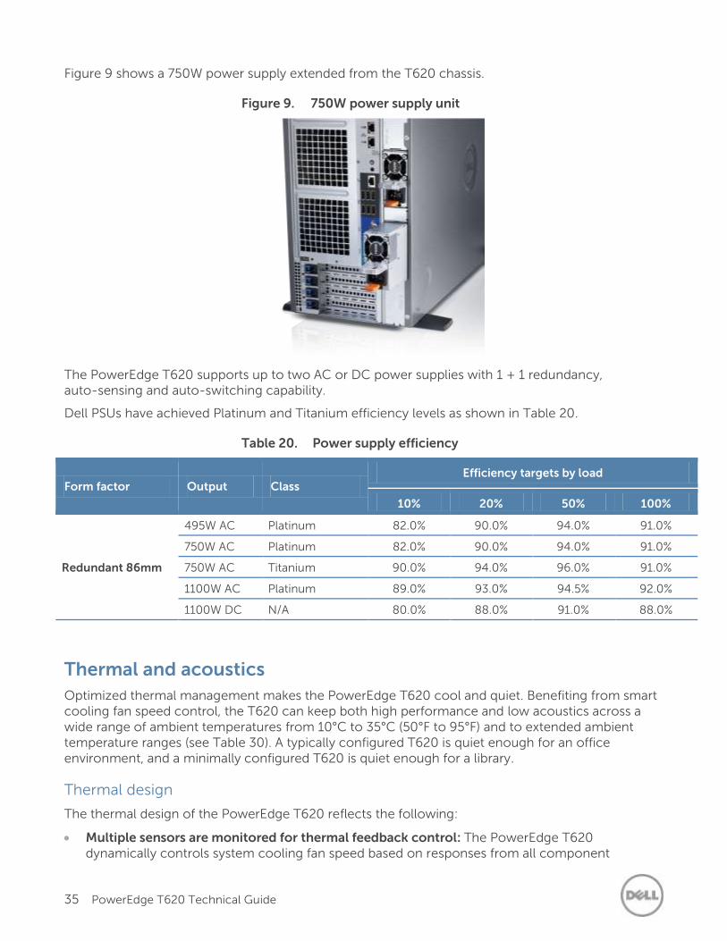
Figure 9 shows a 750W power supply extended from the T620 chassis.
Figure 9. 750W power supply unit
The PowerEdge T620 supports up to two AC or DC power supplies with 1 + 1 redundancy, auto-sensing and auto-switching capability.
Dell PSUs have achieved Platinum and Titanium efficiency levels as shown in Table 20.
Table 20. Power supply efficiency
Form factor Output Class Efficiency targets by load
10% 20% 50% 100%
Redundant 86mm
495W AC Platinum 82.0% 90.0% 94.0% 91.0%
750W AC Platinum 82.0% 90.0% 94.0% 91.0%
750W AC Titanium 90.0% 94.0% 96.0% 91.0%
1100W AC Platinum 89.0% 93.0% 94.5% 92.0%
1100W DC N/A 80.0% 88.0% 91.0% 88.0%
Thermal and acoustics
Optimized thermal management makes the PowerEdge T620 cool and quiet. Benefiting from smart cooling fan speed control, the T620 can keep both high performance and low acoustics across a wide range of ambient temperatures from 10°C to 35°C (50°F to 95°F) and to extended ambient temperature ranges (see Table 30). A typically configured T620 is quiet enough for an office environment, and a minimally configured T620 is quiet enough for a library.
Thermal design
The thermal design of the PowerEdge T620 reflects the following:
Multiple sensors are monitored for thermal feedback control: The PowerEdge T620 dynamically controls system cooling fan speed based on responses from all component
36 PowerEdge T620 Technical Guide
temperature sensors, including processors, hard disk drives, DIMMs, storage cards, and the inlet ambient temperature. The thermal control also detects and responds to hardware configuration. The thermal management adjusts cooling according to what the system really needs, and draws lower fan power draw and generates lower acoustical noise levels than servers without such controls.
Environmental specifications: The optimized thermal management makes the T620 reliable under a wide range of operating environments. Many configurations are compliant in expanded operating temperature environments, but a few are not. For environmental specifications and for configuration limitations on expanded operating temperature environments, see Table 30 in Appendix A.
Acoustical design
The acoustical design of the PowerEdge T620 reflects the following:
Quiet library acoustics: The PowerEdge T620 is quiet enough for a library when minimally configured or quiet enough for an office setting in a typical configuration.
Adherence to Dell’s high sound quality standards: Sound quality is different from sound power level and sound pressure level in that it describes how humans respond to annoyances in sound, like whistles, hums, and so on. One of the sound quality metrics in the Dell specification is prominence ratio of a tone, which is listed in Table 21.
Configurable for low acoustics: The following are configuration considerations you should make if acoustics are important to you:
— Storage devices:
> Because hard drive noise scales with spindle speed, the quietest option for rotational storage media is a 7200-rpm SATA drive. The loudest option is a 15k SAS drive.
> Solid-state drives are even quieter than rotational drives because they have no sound associated with spinning.
> Noise levels increase with the quantity of hard drives; using fewer hard drives will have a lower acoustical output.
> PCIe SSD cards, such as Fusion-io, require more airflow for cooling, resulting in significantly higher noise levels.
— Redundant fans: Fan noise from the non-redundant, two-fan system is lower than that of the redundant, six-fan system.
— Impacts of cards:
> Quantity of PCIe cards: When more than two PCIe cards are installed, the system fan speed/noise level will be higher.
> Types of PCIe cards: The fan speed/noise level will be higher if a GPU and PERC H710 is installed.
— System Profile settings in BIOS and Thermal settings in iDRAC7 BIOS settings: Performance Per Watt (DAPC or OS) may be quieter than Performance or Dense Configuration (iDRAC Settings > Thermal > Max. Exhaust Temperature or Fan speed offset).
— Hot spare feature of power supply unit: In system default setting, the hot spare feature is disabled; acoustical output from the power supplies is lowest in this setting.
— RAID Setup with PERC H310: A system configured as non-RAID will have a higher noise level than a system configured as RAID.
Noise ramp and descent during bootup from power off: Fan speed noise levels ramp during the boot process (from power off to power on) to add a layer of protection for component
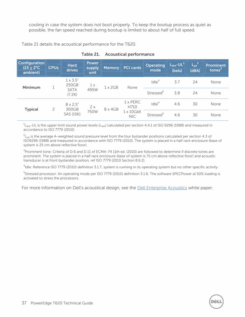
37 PowerEdge T620 Technical Guide
cooling in case the system does not boot properly. To keep the bootup process as quiet as possible, the fan speed reached during bootup is limited to about half of full speed.
Table 21 details the acoustical performance for the T620.
Table 21. Acoustical performance
Configuration (23 ± 2°C ambient)
CPUs Hard
drives
Power supply
unit Memory PCI cards
Operating mode
LWA-UL1
(bels)
LpA2
(dBA)
Prominent tones
3
Minimum 1
1 x 3.5” 250GB SATA (7.2K)
1 x 495W
1 x 2GB None
Idle4 3.7 24 None
Stressed5 3.8 24 None
Typical 2 8 x 2.5” 300GB
SAS (15K)
2 x 750W
8 x 4GB
1 x PERC H710
1 x 10GbE NIC
Idle4 4.6 30 None
Stressed5 4.6 30 None
1LWA-UL is the upper limit sound power levels (LWA) calculated per section 4.4.1 of ISO 9296 (1988) and measured in
accordance to ISO 7779 (2010).
2LpA is the average A-weighted sound pressure level from the four bystander positions calculated per section 4.3 of
ISO9296 (1988) and measured in accordance with ISO 7779 (2010). The system is placed in a half rack enclosure (base of system is 25 cm above reflective floor).
3Prominent tone: Criteria of D.6 and D.11 of ECMA-74 11th ed. (2010) are followed to determine if discrete tones are
prominent. The system is placed in a half rack enclosure (base of system is 75 cm above reflective floor) and acoustic transducer is at front bystander position, ref ISO 7779 (2010 Section 8.6.2).
4Idle: Reference ISO 7779 (2010) definition 3.1.7; system is running in its operating system but no other specific activity.
5Stressed processor: An operating mode per ISO 7779 (2010) definition 3.1.6. The software SPECPower at 50% loading is
activated to stress the processors.
For more information on Dell’s acoustical design, see the Dell Enterprise Acoustics white paper.
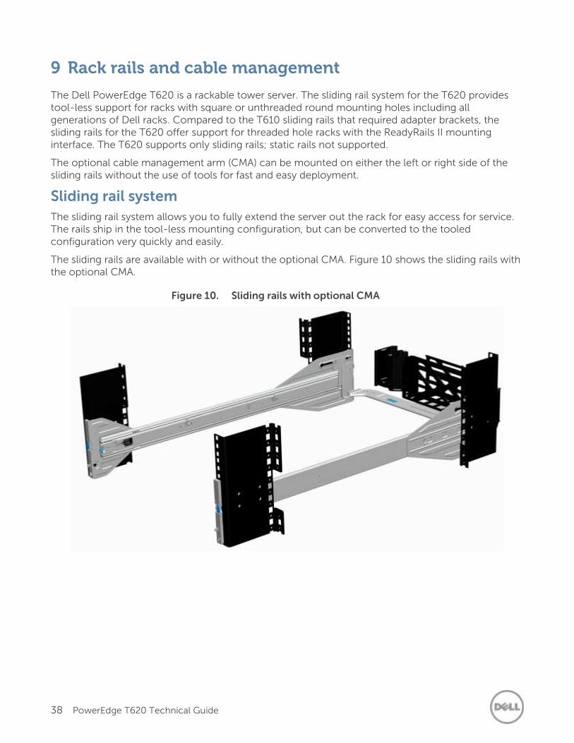
38 PowerEdge T620 Technical Guide
9 Rack rails and cable management
The Dell PowerEdge T620 is a rackable tower server. The sliding rail system for the T620 provides tool-less support for racks with square or unthreaded round mounting holes including all generations of Dell racks. Compared to the T610 sliding rails that required adapter brackets, the sliding rails for the T620 offer support for threaded hole racks with the ReadyRails II mounting interface. The T620 supports only sliding rails; static rails not supported.
The optional cable management arm (CMA) can be mounted on either the left or right side of the sliding rails without the use of tools for fast and easy deployment.
Sliding rail system
The sliding rail system allows you to fully extend the server out the rack for easy access for service. The rails ship in the tool-less mounting configuration, but can be converted to the tooled configuration very quickly and easily.
The sliding rails are available with or without the optional CMA. Figure 10 shows the sliding rails with the optional CMA.
Figure 10. Sliding rails with optional CMA
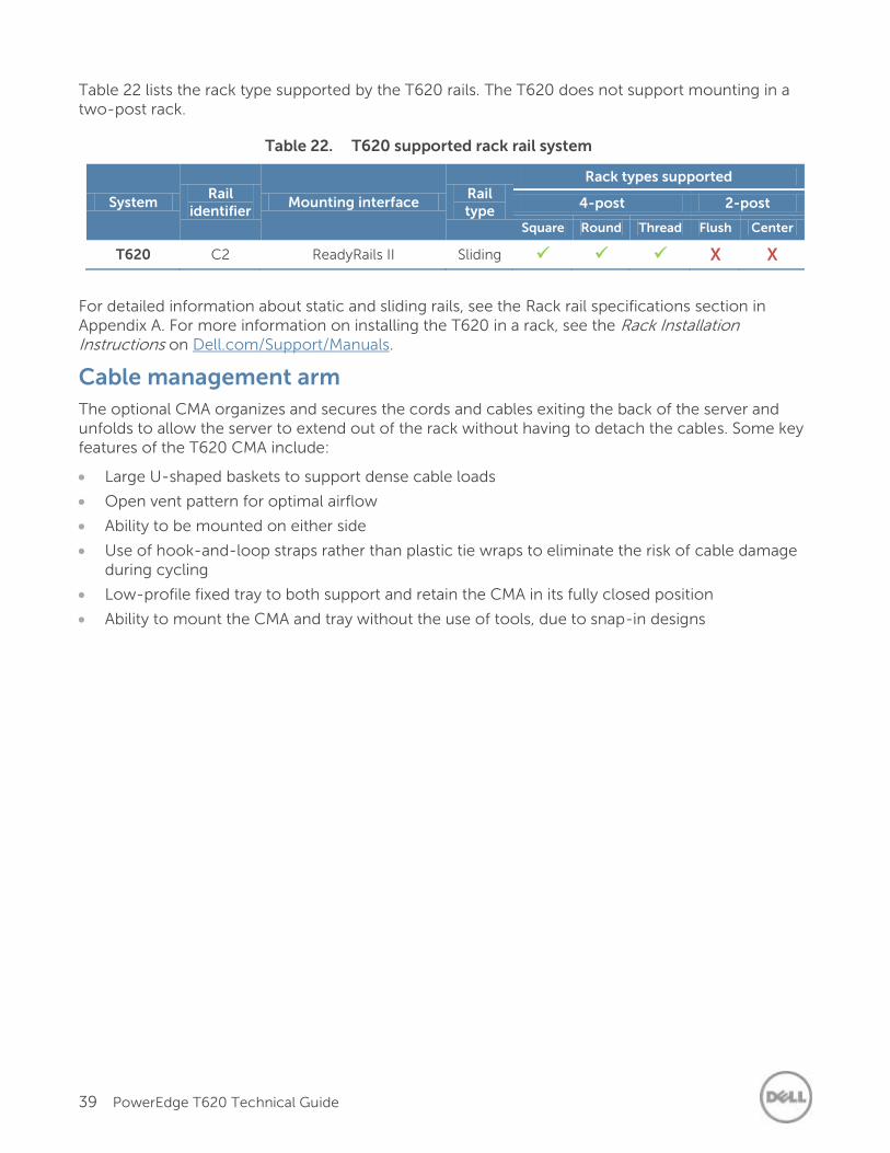
39 PowerEdge T620 Technical Guide
Table 22 lists the rack type supported by the T620 rails. The T620 does not support mounting in a two-post rack.
Table 22. T620 supported rack rail system
System Rail
identifier Mounting interface
Rail type
Rack types supported
4-post 2-post
Square Round Thread Flush Center
T620 C2 ReadyRails II Sliding X X
For detailed information about static and sliding rails, see the Rack rail specifications section in Appendix A. For more information on installing the T620 in a rack, see the Rack Installation Instructions on Dell.com/Support/Manuals.
Cable management arm
The optional CMA organizes and secures the cords and cables exiting the back of the server and unfolds to allow the server to extend out of the rack without having to detach the cables. Some key features of the T620 CMA include:
Large U-shaped baskets to support dense cable loads
Open vent pattern for optimal airflow
Ability to be mounted on either side
Use of hook-and-loop straps rather than plastic tie wraps to eliminate the risk of cable damage during cycling
Low-profile fixed tray to both support and retain the CMA in its fully closed position
Ability to mount the CMA and tray without the use of tools, due to snap-in designs
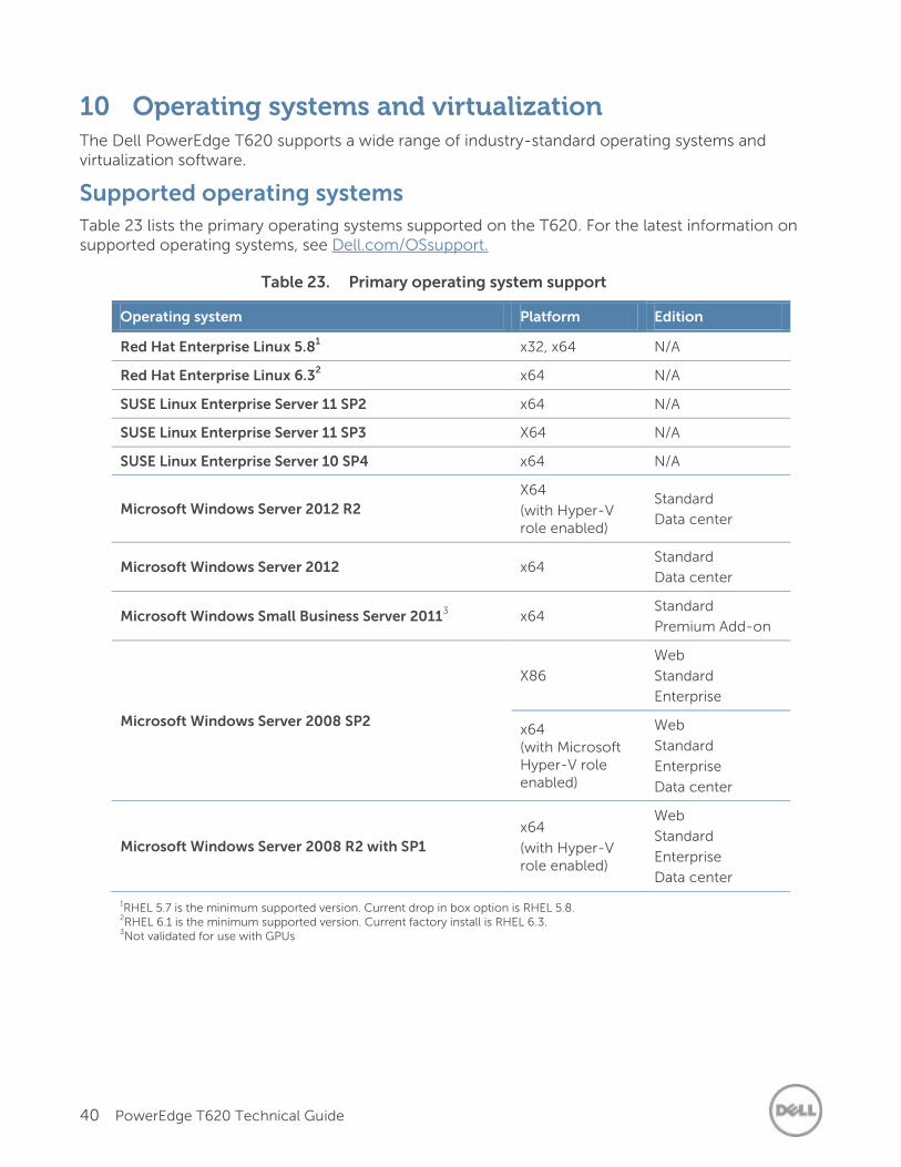
40 PowerEdge T620 Technical Guide
10 Operating systems and virtualization The Dell PowerEdge T620 supports a wide range of industry-standard operating systems and virtualization software.
Supported operating systems
Table 23 lists the primary operating systems supported on the T620. For the latest information on supported operating systems, see Dell.com/OSsupport.
Table 23. Primary operating system support
Operating system Platform Edition
Red Hat Enterprise Linux 5.81 x32, x64 N/A
Red Hat Enterprise Linux 6.32 x64 N/A
SUSE Linux Enterprise Server 11 SP2 x64 N/A
SUSE Linux Enterprise Server 11 SP3 X64 N/A
SUSE Linux Enterprise Server 10 SP4 x64 N/A
Microsoft Windows Server 2012 R2
X64
(with Hyper-V role enabled)
Standard
Data center
Microsoft Windows Server 2012 x64 Standard
Data center
Microsoft Windows Small Business Server 20113 x64
Standard
Premium Add-on
Microsoft Windows Server 2008 SP2
X86
Web
Standard
Enterprise
x64 (with Microsoft Hyper-V role enabled)
Web
Standard
Enterprise
Data center
Microsoft Windows Server 2008 R2 with SP1
x64
(with Hyper-V role enabled)
Web
Standard
Enterprise
Data center
1RHEL 5.7 is the minimum supported version. Current drop in box option is RHEL 5.8. 2RHEL 6.1 is the minimum supported version. Current factory install is RHEL 6.3. 3Not validated for use with GPUs
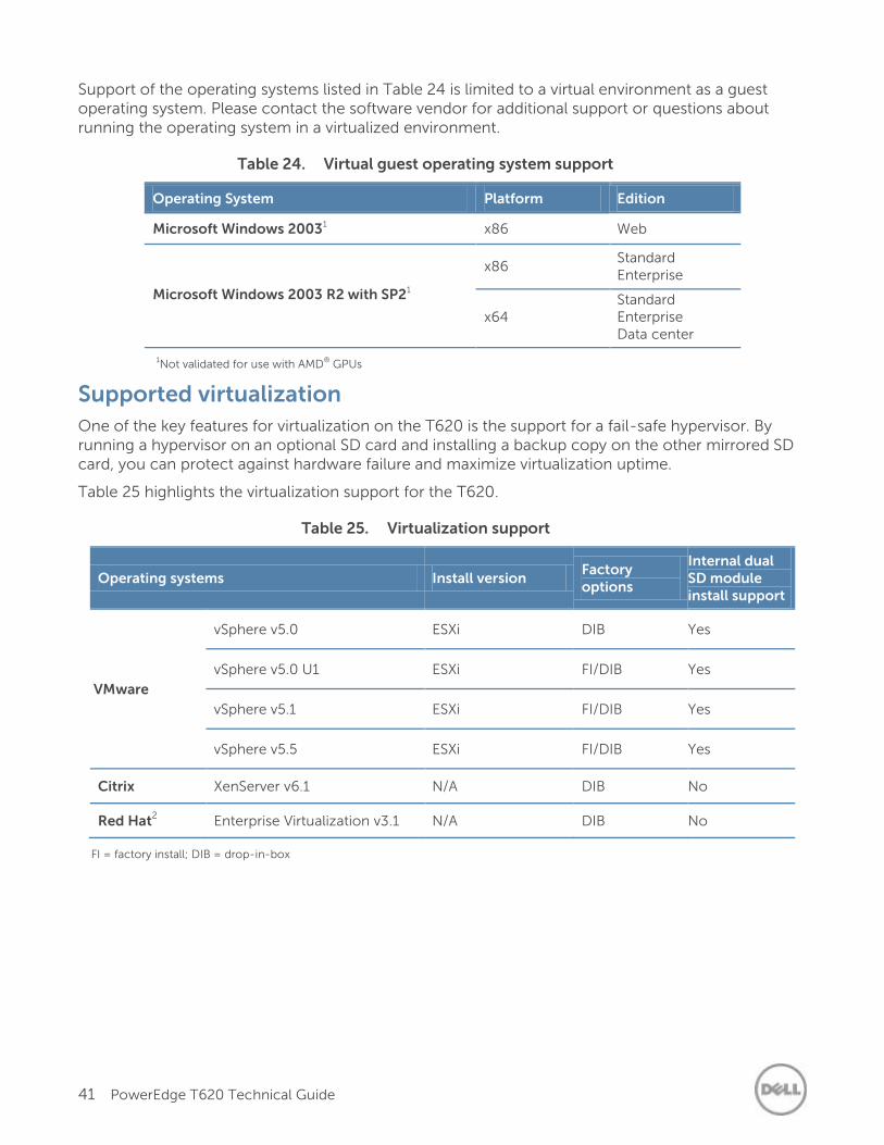
41 PowerEdge T620 Technical Guide
Support of the operating systems listed in Table 24 is limited to a virtual environment as a guest operating system. Please contact the software vendor for additional support or questions about running the operating system in a virtualized environment.
Table 24. Virtual guest operating system support
Operating System Platform Edition
Microsoft Windows 20031 x86 Web
Microsoft Windows 2003 R2 with SP21
x86 Standard Enterprise
x64 Standard Enterprise Data center
1Not validated for use with AMD® GPUs
Supported virtualization
One of the key features for virtualization on the T620 is the support for a fail-safe hypervisor. By running a hypervisor on an optional SD card and installing a backup copy on the other mirrored SD card, you can protect against hardware failure and maximize virtualization uptime.
Table 25 highlights the virtualization support for the T620.
Table 25. Virtualization support
Operating systems Install version Factory options
Internal dual SD module install support
VMware
vSphere v5.0 ESXi DIB Yes
vSphere v5.0 U1 ESXi FI/DIB Yes
vSphere v5.1 ESXi FI/DIB Yes
vSphere v5.5 ESXi FI/DIB Yes
Citrix XenServer v6.1 N/A DIB No
Red Hat2 Enterprise Virtualization v3.1 N/A DIB No
FI = factory install; DIB = drop-in-box
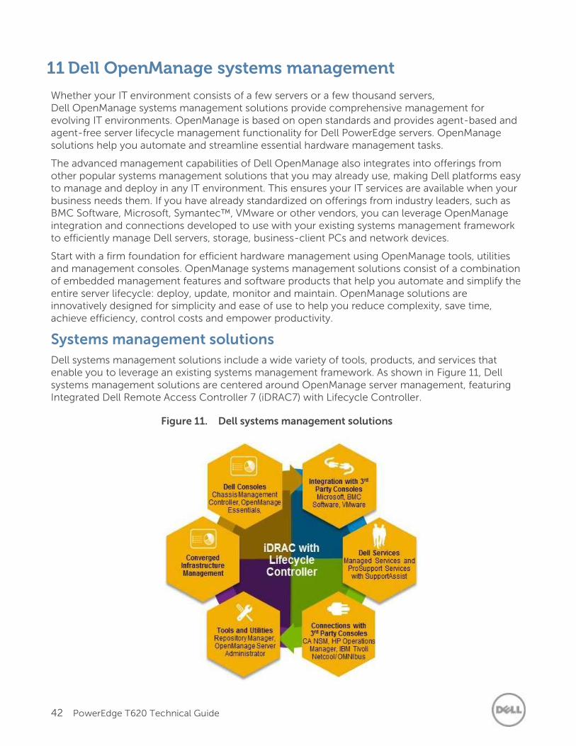
42 PowerEdge T620 Technical Guide
11 Dell OpenManage systems management
Whether your IT environment consists of a few servers or a few thousand servers, Dell OpenManage systems management solutions provide comprehensive management for evolving IT environments. OpenManage is based on open standards and provides agent-based and agent-free server lifecycle management functionality for Dell PowerEdge servers. OpenManage solutions help you automate and streamline essential hardware management tasks.
The advanced management capabilities of Dell OpenManage also integrates into offerings from other popular systems management solutions that you may already use, making Dell platforms easy to manage and deploy in any IT environment. This ensures your IT services are available when your business needs them. If you have already standardized on offerings from industry leaders, such as BMC Software, Microsoft, Symantec™, VMware or other vendors, you can leverage OpenManage integration and connections developed to use with your existing systems management framework to efficiently manage Dell servers, storage, business-client PCs and network devices.
Start with a firm foundation for efficient hardware management using OpenManage tools, utilities and management consoles. OpenManage systems management solutions consist of a combination of embedded management features and software products that help you automate and simplify the entire server lifecycle: deploy, update, monitor and maintain. OpenManage solutions are innovatively designed for simplicity and ease of use to help you reduce complexity, save time, achieve efficiency, control costs and empower productivity.
Systems management solutions
Dell systems management solutions include a wide variety of tools, products, and services that enable you to leverage an existing systems management framework. As shown in Figure 11, Dell systems management solutions are centered around OpenManage server management, featuring Integrated Dell Remote Access Controller 7 (iDRAC7) with Lifecycle Controller.
Figure 11. Dell systems management solutions
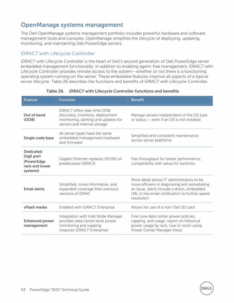
43 PowerEdge T620 Technical Guide
OpenManage systems management
The Dell OpenManage systems management portfolio includes powerful hardware and software management tools and consoles. OpenManage simplifies the lifecycle of deploying, updating, monitoring, and maintaining Dell PowerEdge servers.
iDRAC7 with Lifecycle Controller
iDRAC7 with Lifecycle Controller is the heart of Dell’s second generation of Dell PowerEdge server embedded management functionality. In addition to enabling agent-free management, iDRAC7 with Lifecycle Controller provides remote access to the system—whether or not there is a functioning operating system running on the server. These embedded features improve all aspects of a typical server lifecycle. Table 26 describes the functions and benefits of iDRAC7 with Lifecycle Controller.
Table 26. iDRAC7 with Lifecycle Controller functions and benefits
Feature Function Benefit
Out of band (OOB)
iDRAC7 offers real-time OOB discovery, inventory, deployment monitoring, alerting and updates for servers and internal storage
Manage servers independent of the OS type or status — even if an OS is not installed
Single code base All server types have the same embedded management hardware and firmware
Simplified and consistent maintenance across server platforms
Dedicated GigE port
(PowerEdge rack and tower systems)
Gigabit Ethernet replaces 10/100 on predecessor iDRAC6
Fast throughput for better performance; compatibility with setup for switches
Email alerts Simplified, more informative, and expanded coverage than previous versions of iDRAC
More detail allows IT administrators to be more efficient in diagnosing and remediating an issue; alerts include a direct, embedded URL in the email notification to further speed resolution
vFlash media Enabled with iDRAC7 Enterprise Allows for use of a non-Dell SD card
Enhanced power management
Integration with Intel Node Manager provides data center level power monitoring and capping (requires iDRAC7 Enterprise)
Fine tune data center power policies, capping, and usage; report on historical power usage by rack, row or room using Power Center Manager (new)
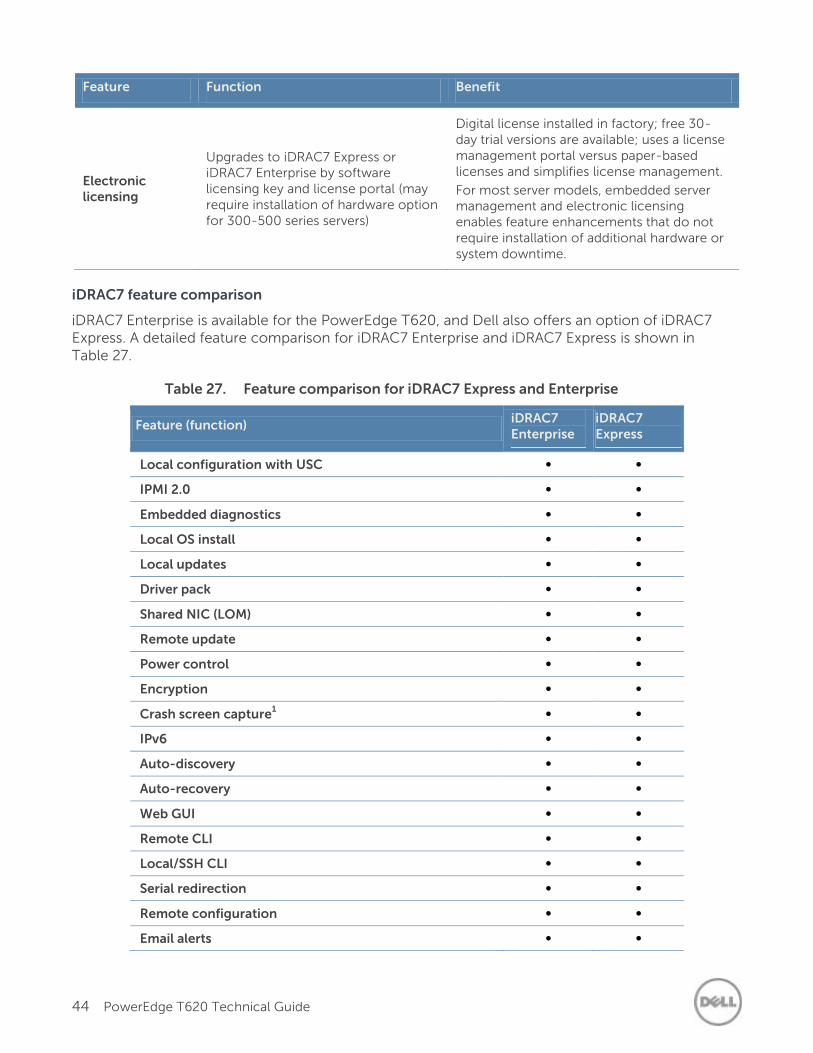
44 PowerEdge T620 Technical Guide
Feature Function Benefit
Electronic licensing
Upgrades to iDRAC7 Express or iDRAC7 Enterprise by software licensing key and license portal (may require installation of hardware option for 300-500 series servers)
Digital license installed in factory; free 30-day trial versions are available; uses a license management portal versus paper-based licenses and simplifies license management.
For most server models, embedded server management and electronic licensing enables feature enhancements that do not require installation of additional hardware or system downtime.
iDRAC7 feature comparison
iDRAC7 Enterprise is available for the PowerEdge T620, and Dell also offers an option of iDRAC7 Express. A detailed feature comparison for iDRAC7 Enterprise and iDRAC7 Express is shown in Table 27.
Table 27. Feature comparison for iDRAC7 Express and Enterprise
Feature (function) iDRAC7 Enterprise
iDRAC7 Express
Local configuration with USC ∞ ∞
IPMI 2.0 ∞ ∞
Embedded diagnostics ∞ ∞
Local OS install ∞ ∞
Local updates ∞ ∞
Driver pack ∞ ∞
Shared NIC (LOM)
∞ ∞
Remote update ∞ ∞
Power control ∞ ∞
Encryption ∞ ∞
Crash screen capture1 ∞ ∞
IPv6 ∞ ∞
Auto-discovery ∞ ∞
Auto-recovery ∞ ∞
Web GUI ∞ ∞
Remote CLI ∞ ∞
Local/SSH CLI ∞ ∞
Serial redirection ∞ ∞
Remote configuration ∞ ∞
Email alerts ∞ ∞
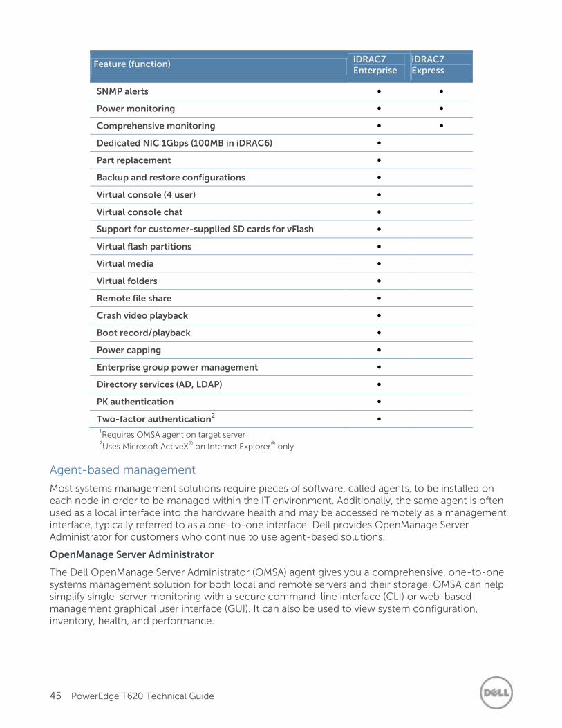
45 PowerEdge T620 Technical Guide
Feature (function) iDRAC7 Enterprise
iDRAC7 Express
SNMP alerts ∞ ∞
Power monitoring ∞ ∞
Comprehensive monitoring ∞ ∞
Dedicated NIC 1Gbps (100MB in iDRAC6) ∞
Part replacement ∞
Backup and restore configurations ∞
Virtual console (4 user) ∞
Virtual console chat ∞
Support for customer-supplied SD cards for vFlash media
∞
Virtual flash partitions ∞
Virtual media ∞
Virtual folders ∞
Remote file share ∞
Crash video playback ∞
Boot record/playback ∞
Power capping ∞
Enterprise group power management ∞
Directory services (AD, LDAP) ∞
PK authentication ∞
Two-factor authentication2 ∞
1Requires OMSA agent on target server
2Uses Microsoft ActiveX
® on Internet Explorer
® only
Agent-based management
Most systems management solutions require pieces of software, called agents, to be installed on each node in order to be managed within the IT environment. Additionally, the same agent is often used as a local interface into the hardware health and may be accessed remotely as a management interface, typically referred to as a one-to-one interface. Dell provides OpenManage Server Administrator for customers who continue to use agent-based solutions.
OpenManage Server Administrator
The Dell OpenManage Server Administrator (OMSA) agent gives you a comprehensive, one-to-one systems management solution for both local and remote servers and their storage. OMSA can help simplify single-server monitoring with a secure command-line interface (CLI) or web-based management graphical user interface (GUI). It can also be used to view system configuration, inventory, health, and performance.
46 PowerEdge T620 Technical Guide
Agent-free management
Because Dell PowerEdge servers have embedded server lifecycle management, in many cases, there is no need to install an OpenManage systems management software agent into the operating system of a Dell PowerEdge server. This greatly simplifies and streamlines the management footprint.
Dell consoles
The central console in a systems management solution is often referred to as the one-to-many console. The central console provides a rapid view and insight into the overall health of all systems in the IT environment. The Dell systems management portfolio includes several powerful consoles, depending upon your needs, including the following:
Dell OpenManage Essentials: OpenManage Essentials (OME) is a recently released systems management console that provides a comprehensive view of Dell systems, devices and components in an enterprise network. It is used to monitor Dell PowerEdge servers, EqualLogic and PowerVault storage, and Dell Networking switches; to update and configure Dell servers; and to create asset reports. OpenManage Essentials also communicates health status alerts for Dell servers, storage, and network devices to the Dell KACE™ K1000 service desk. OpenManage Essentials is available as a no-charge software download from Dell.com/Support.
OpenManage systems management tools and utilities
Dell OpenManage systems management tools and utilities consist of the following:
Dell Repository Manager: The Dell Repository Manager (RM) is a standalone GUI-based productivity tool that helps simplify the process of managing downloads and baseline BIOS, firmware, and driver updates. Repository Manager can create deployment disks as well as create and manage customized repositories.
Dell OpenManage Server Update Utility: The Dell Server Update Utility (SUU) is a DVD-based application for identifying and applying BIOS and firmware updates to Dell PowerEdge servers.
Dell OpenManage Systems Build and Update Utility: The Dell System Build and Update Utility (SBUU) provides one-to-one and one-to-many deployment and single-server update capabilities in the pre-operating system environment.
Dell Update Packages: The Dell Update Packages (DUP) is a self-contained executable in a standard package format that updates a software element on a Dell server such as the BIOS, a driver, firmware, and other software updates.
Dell OpenManage Deployment Toolkit: The Dell OpenManage Deployment Toolkit (DTK) is a CLI-based tool that includes a set of utilities for configuring and deploying Dell PowerEdge systems, and can be used to build scripted, unattended OS installations to deploy large numbers of servers in a reliable fashion.
RACADM: The RACADM command-line utility provides a scriptable interface that allows you to locally or remotely configure iDRAC7.
IPMITool: IPMITool includes scriptable console application programs used to control and manage remote systems using the IPMI version 1.5 and later protocol.
Integration with third-party consoles
Dell OpenManage easily integrates with several leading third-party consoles, including:
Dell Server Management Pack Suite for Microsoft System Center Operations Manager (SCOM): This suite of server management packs enables several functions through System Center Operations Manager, including in-band discovery and monitoring of racks and
47 PowerEdge T620 Technical Guide
towers, out-of-band discovery and monitoring through iDRAC7 with Lifecycle Controller, as well as performance and advanced monitoring.
Dell Lifecycle Controller Integration (DLCI) for Microsoft System Center Configuration Manager (SCCM): This pack contains Dell Lifecycle Controller Integration (DLCI), which integrates OpenManage functions in SCCM to manage the Dell PowerEdge servers, including auto-discovery, operating system deployment and configuration of hardware elements, (RAID, NIC, BIOS, iDRAC), OS and hypervisor agnostic updates, firmware management, and system viewer utilities.
Dell Server PRO Management Pack for Microsoft System Center Virtual Machine Manager (SCVMM): This pack manages Dell physical servers and hosts of virtual machines (VMs) by using Microsoft System Center Operations Manager/System Center Essentials (SCOM/SCE) and System Center Virtual Machine Manager (SCVMM). It provides guidance for remedial actions based on alerts to best manage virtual machines and handle the impacts appropriately.
OpenManage Integration for VMware vCenter: This plug-in allows IT administrators to monitor, provision, and manage the physical PowerEdge server hardware and firmware from a dedicated Dell menu accessed through the VMware vCenter console using the same role-based access control model as vCenter, combining physical server management.
BMC Software: Dell and BMC Software work together to simplify IT by ensuring tight integration between Dell server, storage, and network management functionality and the BMC Software process and data center automation products.
OpenManage connections with third-party consoles
Dell OpenManage provides connections with many third-party consoles, including:
Dell OpenManage Connection for Computer Associates Network and Systems Management: This connection allows you to monitor PowerEdge servers and PowerVault storage arrays from within the Computer Associates Network and Systems Management (CANSM) console.
Dell OpenManage Connection for HP Operations Manager: This connection enables several functions through HP Operations Manager, including auto-grouping, SNMP trap reception, global health monitoring, and a context-sensitive launch of OpenManage Server Administrator.
Dell OpenManage Connection for IBM Tivoli Netcool/OMNIBus: This connection provides event monitoring capabilities to monitor Dell PowerEdge servers and Dell EqualLogic systems. It allows event monitoring, automatic event correlation, and launching device consoles from the Netcool/OMNIbus console.
Dell server management operations
Dell OpenManage systems management is centered on automating the server management lifecycle — deploy, update, monitor, and maintain. To manage an infrastructure properly and efficiently, you must perform all of these functions easily and quickly. iDRAC7 with Lifecycle Controller technology provides you with these intelligent capabilities embedded within the server infrastructure. This allows you to invest more time and energy on business improvements and less on maintenance.
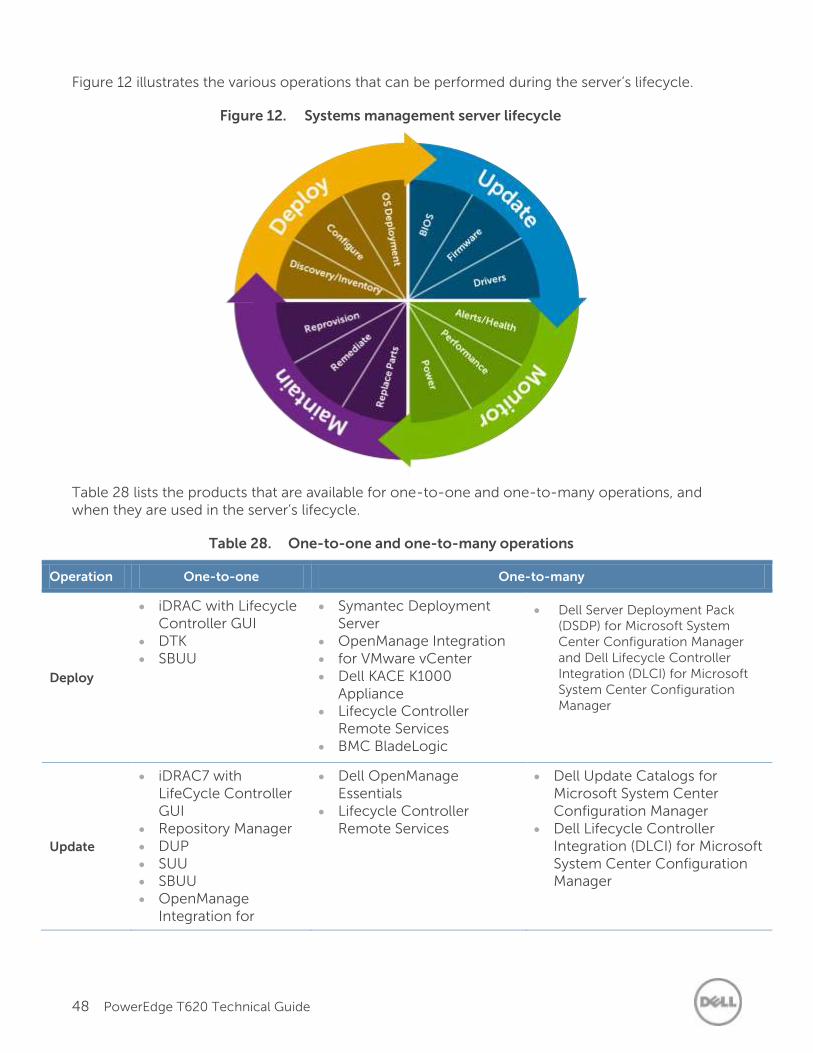
48 PowerEdge T620 Technical Guide
Figure 12 illustrates the various operations that can be performed during the server’s lifecycle.
Figure 12. Systems management server lifecycle
Table 28 lists the products that are available for one-to-one and one-to-many operations, and when they are used in the server’s lifecycle.
Table 28. One-to-one and one-to-many operations
Operation One-to-one One-to-many
Deploy
iDRAC with Lifecycle Controller GUI
DTK SBUU
Symantec Deployment Server
OpenManage Integration for VMware vCenter Dell KACE K1000
Appliance Lifecycle Controller
Remote Services BMC BladeLogic
integration with Lifecycle Controller
Dell Server Deployment Pack (DSDP) for Microsoft System Center Configuration Manager and Dell Lifecycle Controller Integration (DLCI) for Microsoft System Center Configuration Manager
Update
iDRAC7 with LifeCycle Controller GUI
Repository Manager DUP SUU SBUU OpenManage
Integration for VMware vCenter
Dell OpenManage Essentials
Lifecycle Controller Remote Services
Dell Update Catalogs for Microsoft System Center Configuration Manager
Dell Lifecycle Controller Integration (DLCI) for Microsoft System Center Configuration Manager
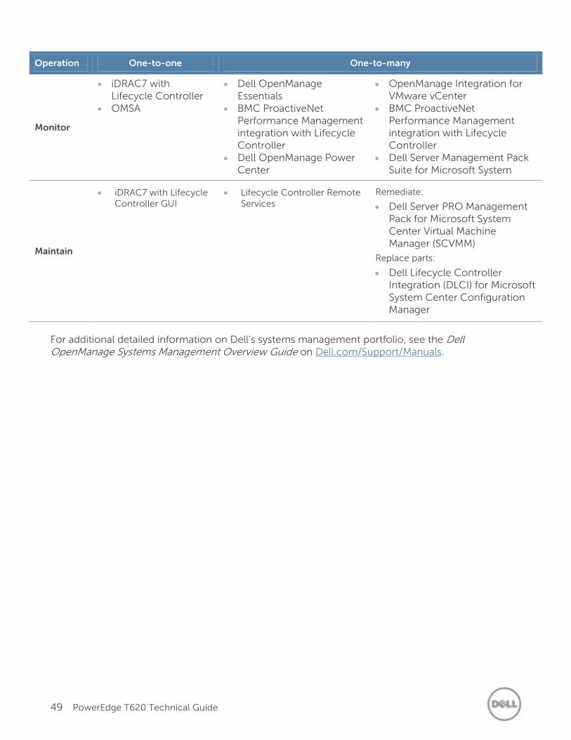
49 PowerEdge T620 Technical Guide
Operation One-to-one One-to-many
Monitor
iDRAC7 with Lifecycle Controller
OMSA
Dell OpenManage Essentials
BMC ProactiveNet Performance Management integration with Lifecycle Controller
Dell OpenManage Power Center
OpenManage Integration for VMware vCenter
BMC ProactiveNet Performance Management integration with Lifecycle Controller
Dell Server Management Pack Suite for Microsoft System Center Operations Manager (SCOM)
Maintain
iDRAC7 with Lifecycle Controller GUI
Lifecycle Controller Remote Services
Remediate:
Dell Server PRO Management Pack for Microsoft System Center Virtual Machine Manager (SCVMM)
Replace parts:
Dell Lifecycle Controller Integration (DLCI) for Microsoft System Center Configuration Manager
For additional detailed information on Dell’s systems management portfolio, see the Dell OpenManage Systems Management Overview Guide on Dell.com/Support/Manuals.
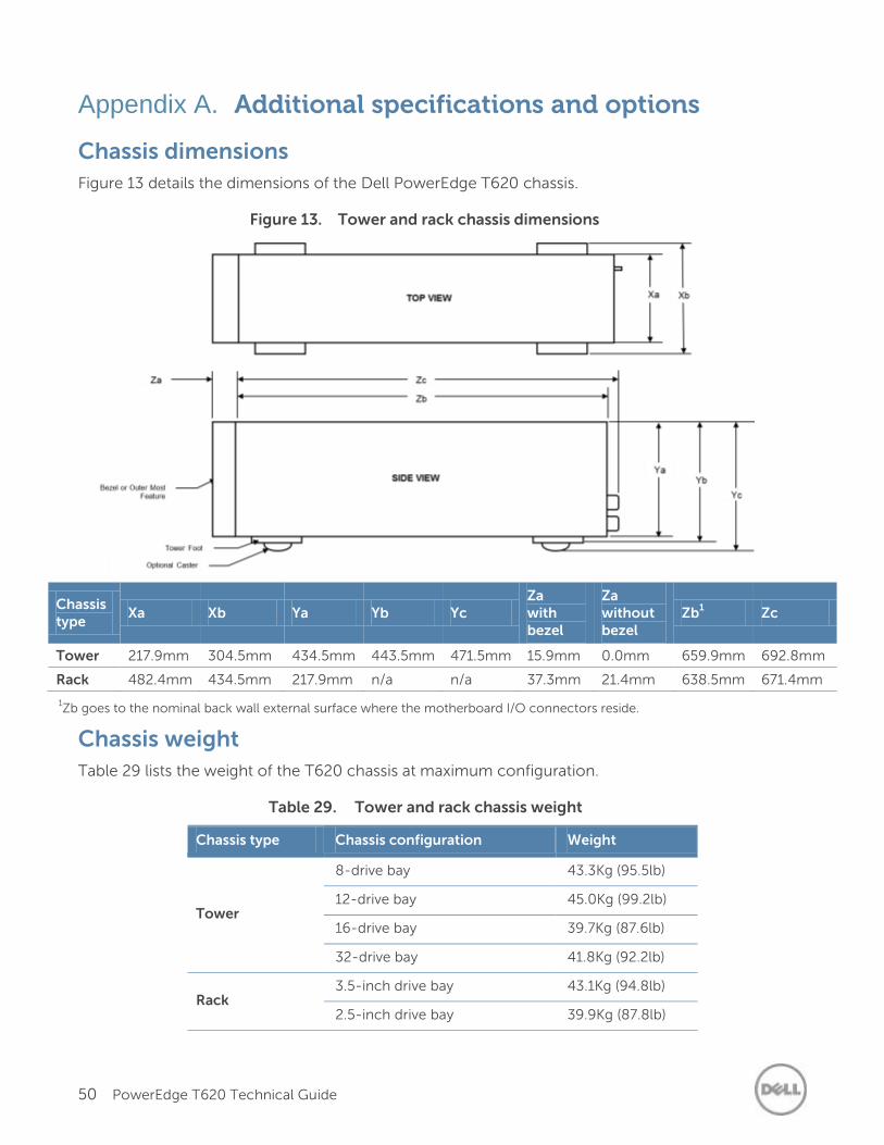
50 PowerEdge T620 Technical Guide
Appendix A. Additional specifications and options
Chassis dimensions
Figure 13 details the dimensions of the Dell PowerEdge T620 chassis.
Figure 13. Tower and rack chassis dimensions
Chassis type
Xa Xb Ya Yb Yc Za with bezel
Za without bezel
Zb1 Zc
Tower 217.9mm 304.5mm 434.5mm 443.5mm 471.5mm 15.9mm 0.0mm 659.9mm 692.8mm
Rack 482.4mm 434.5mm 217.9mm n/a n/a 37.3mm 21.4mm 638.5mm 671.4mm
1Zb goes to the nominal back wall external surface where the motherboard I/O connectors reside.
Chassis weight
Table 29 lists the weight of the T620 chassis at maximum configuration.
Table 29. Tower and rack chassis weight
Chassis type Chassis configuration Weight
Tower
8-drive bay 43.3Kg (95.5lb)
12-drive bay 45.0Kg (99.2lb)
16-drive bay 39.7Kg (87.6lb)
32-drive bay 41.8Kg (92.2lb)
Rack 3.5-inch drive bay 43.1Kg (94.8lb)
2.5-inch drive bay 39.9Kg (87.8lb)
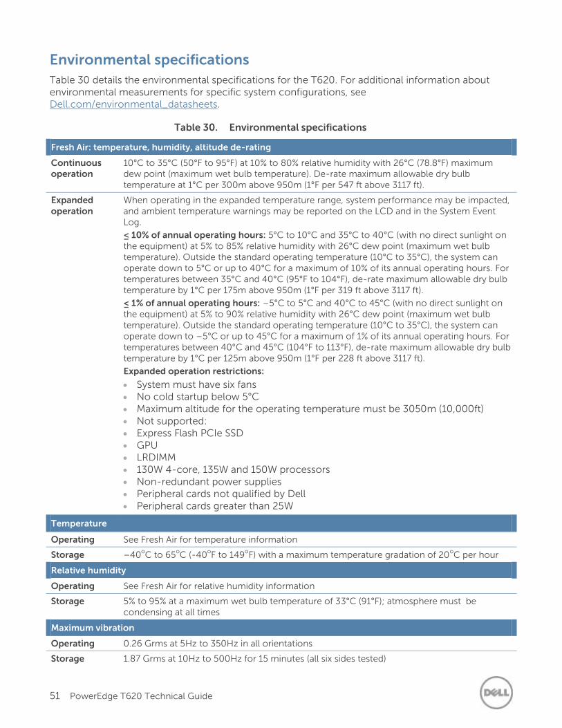
51 PowerEdge T620 Technical Guide
Environmental specifications
Table 30 details the environmental specifications for the T620. For additional information about environmental measurements for specific system configurations, see Dell.com/environmental_datasheets.
Table 30. Environmental specifications
Fresh Air: temperature, humidity, altitude de-rating
Continuous operation
10°C to 35°C (50°F to 95°F) at 10% to 80% relative humidity with 26°C (78.8°F) maximum dew point (maximum wet bulb temperature). De-rate maximum allowable dry bulb temperature at 1°C per 300m above 950m (1°F per 547 ft above 3117 ft).
Expanded operation
When operating in the expanded temperature range, system performance may be impacted, and ambient temperature warnings may be reported on the LCD and in the System Event Log.
≤ 10% of annual operating hours: 5°C to 10°C and 35°C to 40°C (with no direct sunlight on the equipment) at 5% to 85% relative humidity with 26°C dew point (maximum wet bulb temperature). Outside the standard operating temperature (10°C to 35°C), the system can operate down to 5°C or up to 40°C for a maximum of 10% of its annual operating hours. For temperatures between 35°C and 40°C (95°F to 104°F), de-rate maximum allowable dry bulb temperature by 1°C per 175m above 950m (1°F per 319 ft above 3117 ft).
≤ 1% of annual operating hours: –5°C to 5°C and 40°C to 45°C (with no direct sunlight on the equipment) at 5% to 90% relative humidity with 26°C dew point (maximum wet bulb temperature). Outside the standard operating temperature (10°C to 35°C), the system can operate down to –5°C or up to 45°C for a maximum of 1% of its annual operating hours. For temperatures between 40°C and 45°C (104°F to 113°F), de-rate maximum allowable dry bulb temperature by 1°C per 125m above 950m (1°F per 228 ft above 3117 ft).
Expanded operation restrictions:
System must have six fans No cold startup below 5°C Maximum altitude for the operating temperature must be 3050m (10,000ft) Not supported: Express Flash PCIe SSD GPU LRDIMM 130W 4-core, 135W and 150W processors Non-redundant power supplies Peripheral cards not qualified by Dell Peripheral cards greater than 25W
Temperature
Operating See Fresh Air for temperature information
Storage –40oC to 65
oC (-40
oF to 149
oF) with a maximum temperature gradation of 20
oC per hour
Relative humidity
Operating See Fresh Air for relative humidity information
Storage 5% to 95% at a maximum wet bulb temperature of 33°C (91°F); atmosphere must be condensing at all times
Maximum vibration
Operating 0.26 Grms at 5Hz to 350Hz in all orientations
Storage 1.87 Grms at 10Hz to 500Hz for 15 minutes (all six sides tested)
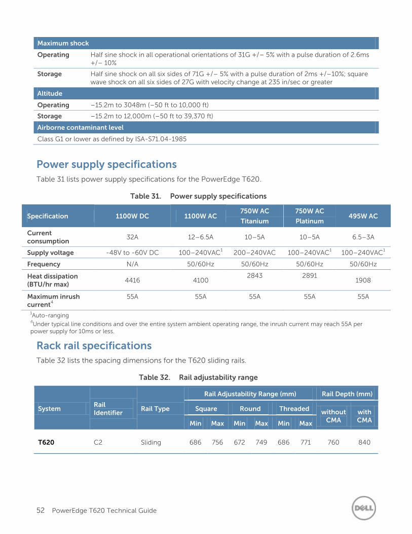
52 PowerEdge T620 Technical Guide
Maximum shock
Operating Half sine shock in all operational orientations of 31G +/– 5% with a pulse duration of 2.6ms +/– 10%
Storage Half sine shock on all six sides of 71G +/– 5% with a pulse duration of 2ms +/–10%; square wave shock on all six sides of 27G with velocity change at 235 in/sec or greater
Altitude
Operating –15.2m to 3048m (–50 ft to 10,000 ft)
Storage –15.2m to 12,000m (–50 ft to 39,370 ft)
Airborne contaminant level
Class G1 or lower as defined by ISA-S71.04-1985
Power supply specifications
Table 31 lists power supply specifications for the PowerEdge T620.
Table 31. Power supply specifications
Specification 1100W DC 1100W AC 750W AC
Titanium
750W AC
Platinum 495W AC
Current consumption
32A 12–6.5A 10–5A 10–5A 6.5–3A
Supply voltage -48V to -60V DC 100–240VAC1 200–240VAC 100–240VAC
1 100–240VAC
1
Frequency N/A 50/60Hz 50/60Hz 50/60Hz 50/60Hz
Heat dissipation (BTU/hr max)
4416 4100 2843
2891 1908
Maximum inrush current
4
55A 55A 55A 55A 55A
1Auto-ranging
4Under typical line conditions and over the entire system ambient operating range, the inrush current may reach 55A per
power supply for 10ms or less.
Rack rail specifications
Table 32 lists the spacing dimensions for the T620 sliding rails.
Table 32. Rail adjustability range
System Rail Identifier
Rail Type
Rail Adjustability Range (mm) Rail Depth (mm)
Square Round Threaded without CMA
with CMA Min Max Min Max Min Max
T620 C2 Sliding 686 756 672 749 686 771 760 840
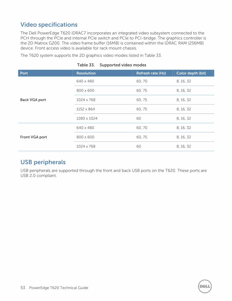
53 PowerEdge T620 Technical Guide
Video specifications
The Dell PowerEdge T620 iDRAC7 incorporates an integrated video subsystem connected to the PCH through the PCIe and internal PCIe switch and PCIe to PCI-bridge. The graphics controller is the 2D Matrox G200. The video frame buffer (16MB) is contained within the iDRAC RAM (256MB) device. Front access video is available for rack mount chassis.
The T620 system supports the 2D graphics video modes listed in Table 33.
Table 33. Supported video modes
Port Resolution Refresh rate (Hz) Color depth (bit)
Back VGA port
640 x 480 60, 70 8, 16, 32
800 x 600 60, 75 8, 16, 32
1024 x 768 60, 75 8, 16, 32
1152 x 864 60, 75 8, 16, 32
1280 x 1024 60 8, 16, 32
Front VGA port
640 x 480 60, 70 8, 16, 32
800 x 600 60, 75 8, 16, 32
1024 x 768 60 8, 16, 32
USB peripherals
USB peripherals are supported through the front and back USB ports on the T620. These ports are USB 2.0 compliant.
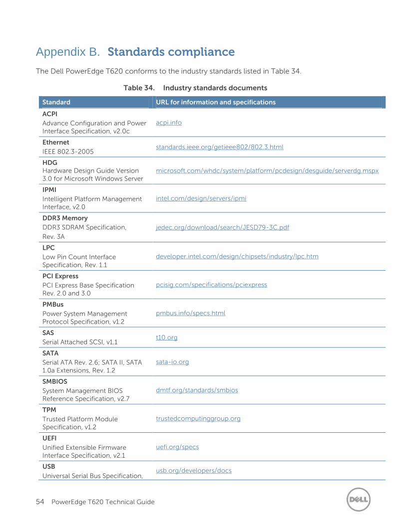
54 PowerEdge T620 Technical Guide
Appendix B. Standards compliance
The Dell PowerEdge T620 conforms to the industry standards listed in Table 34.
Table 34. Industry standards documents
Standard URL for information and specifications
ACPI
Advance Configuration and Power Interface Specification, v2.0c
acpi.info
Ethernet
IEEE 802.3-2005 standards.ieee.org/getieee802/802.3.html
HDG Hardware Design Guide Version 3.0 for Microsoft Windows Server
microsoft.com/whdc/system/platform/pcdesign/desguide/serverdg.mspx
IPMI
Intelligent Platform Management Interface, v2.0
intel.com/design/servers/ipmi
DDR3 Memory
DDR3 SDRAM Specification,
Rev. 3A
jedec.org/download/search/JESD79-3C.pdf
LPC
Low Pin Count Interface Specification, Rev. 1.1
developer.intel.com/design/chipsets/industry/lpc.htm
PCI Express
PCI Express Base Specification Rev. 2.0 and 3.0
pcisig.com/specifications/pciexpress
PMBus
Power System Management Protocol Specification, v1.2
pmbus.info/specs.html
SAS
Serial Attached SCSI, v1.1 t10.org
SATA
Serial ATA Rev. 2.6; SATA II, SATA 1.0a Extensions, Rev. 1.2
sata-io.org
SMBIOS
System Management BIOS Reference Specification, v2.7
dmtf.org/standards/smbios
TPM
Trusted Platform Module Specification, v1.2
trustedcomputinggroup.org
UEFI
Unified Extensible Firmware Interface Specification, v2.1
uefi.org/specs
USB
Universal Serial Bus Specification, usb.org/developers/docs
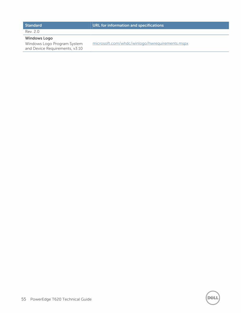
55 PowerEdge T620 Technical Guide
Standard URL for information and specifications
Rev. 2.0
Windows Logo
Windows Logo Program System and Device Requirements, v3.10
microsoft.com/whdc/winlogo/hwrequirements.mspx
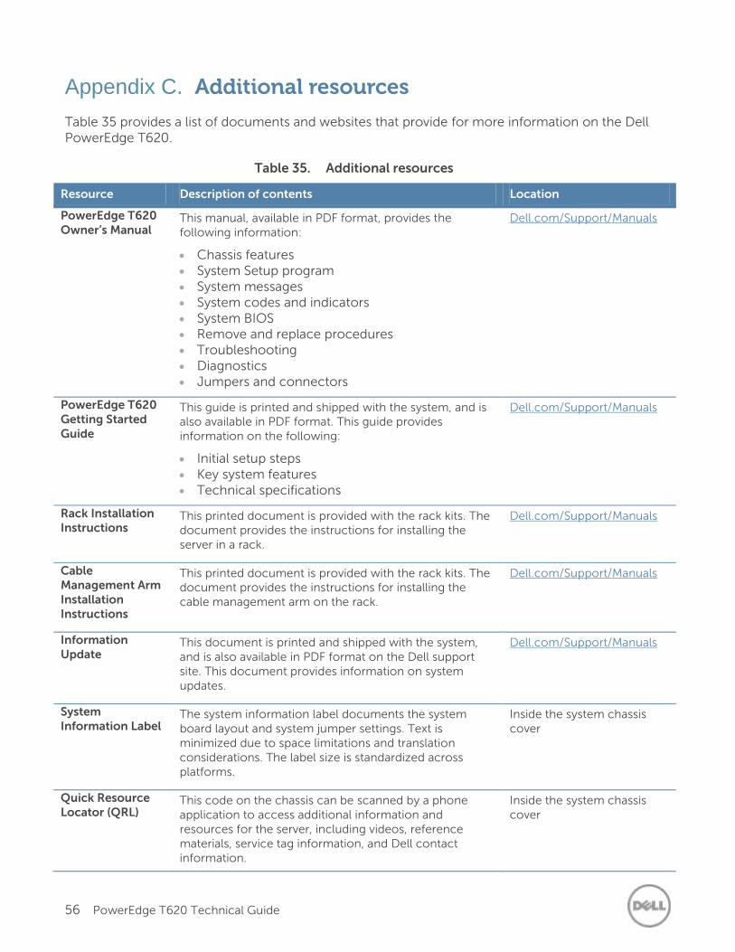
56 PowerEdge T620 Technical Guide
Appendix C. Additional resources
Table 35 provides a list of documents and websites that provide for more information on the Dell PowerEdge T620.
Table 35. Additional resources
Resource Description of contents Location
PowerEdge T620 Owner’s Manual
This manual, available in PDF format, provides the following information:
Chassis features System Setup program System messages System codes and indicators System BIOS Remove and replace procedures Troubleshooting Diagnostics Jumpers and connectors
Dell.com/Support/Manuals
PowerEdge T620 Getting Started Guide
This guide is printed and shipped with the system, and is also available in PDF format. This guide provides information on the following:
Initial setup steps Key system features Technical specifications
Dell.com/Support/Manuals
Rack Installation Instructions
This printed document is provided with the rack kits. The document provides the instructions for installing the server in a rack.
Dell.com/Support/Manuals
Cable Management Arm Installation Instructions
This printed document is provided with the rack kits. The document provides the instructions for installing the cable management arm on the rack.
Dell.com/Support/Manuals
Information Update
This document is printed and shipped with the system, and is also available in PDF format on the Dell support site. This document provides information on system updates.
Dell.com/Support/Manuals
System Information Label
The system information label documents the system board layout and system jumper settings. Text is minimized due to space limitations and translation considerations. The label size is standardized across platforms.
Inside the system chassis cover
Quick Resource Locator (QRL)
This code on the chassis can be scanned by a phone application to access additional information and resources for the server, including videos, reference materials, service tag information, and Dell contact information.
Inside the system chassis cover
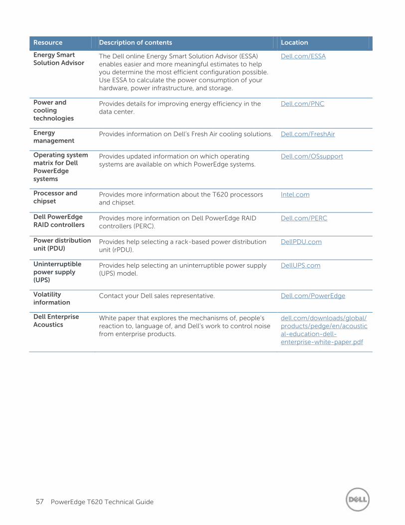
57 PowerEdge T620 Technical Guide
Resource Description of contents Location
Energy Smart Solution Advisor
The Dell online Energy Smart Solution Advisor (ESSA) enables easier and more meaningful estimates to help you determine the most efficient configuration possible. Use ESSA to calculate the power consumption of your hardware, power infrastructure, and storage.
Dell.com/ESSA
Power and cooling technologies
Provides details for improving energy efficiency in the data center.
Dell.com/PNC
Energy management
Provides information on Dell’s Fresh Air cooling solutions. Dell.com/FreshAir
Operating system matrix for Dell PowerEdge systems
Provides updated information on which operating systems are available on which PowerEdge systems.
Dell.com/OSsupport
Processor and chipset
Provides more information about the T620 processors and chipset.
Intel.com
Dell PowerEdge RAID controllers
Provides more information on Dell PowerEdge RAID controllers (PERC).
Dell.com/PERC
Power distribution unit (PDU)
Provides help selecting a rack-based power distribution unit (rPDU).
DellPDU.com
Uninterruptible power supply (UPS)
Provides help selecting an uninterruptible power supply (UPS) model.
DellUPS.com
Volatility information
Contact your Dell sales representative. Dell.com/PowerEdge
Dell Enterprise Acoustics
White paper that explores the mechanisms of, people’s reaction to, language of, and Dell’s work to control noise from enterprise products.
dell.com/downloads/global/products/pedge/en/acoustical-education-dell-enterprise-white-paper.pdf
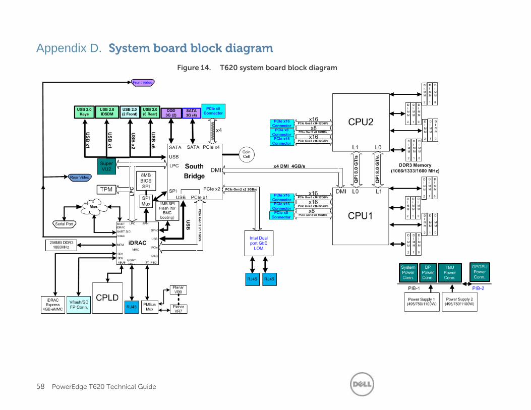
58 PowerEdge T620 Technical Guide
Appendix D. System board block diagram
Figure 14. T620 system board block diagram