Embed Size (px)
Citation preview
Dell Storage CenterSCv2000 and SCv2020 Storage System
Deployment Guide

Notes, Cautions, and WarningsNOTE: A NOTE indicates important information that helps you make better use of your computer.
CAUTION: A CAUTION indicates either potential damage to hardware or loss of data and tells you how to avoid the problem.
WARNING: A WARNING indicates a potential for property damage, personal injury, or death.
Copyright © 2016 Dell Inc. or its subsidiaries. All rights reserved. Dell, EMC, and other trademarks are trademarks of Dell Inc. or its subsidiaries. Other trademarks may be trademarks of their respective owners.
2016 - 12
Rev. A03
Contents
About this Guide................................................................................................................ 7Revision History..................................................................................................................................................................7Audience.............................................................................................................................................................................7Contacting Dell................................................................................................................................................................... 7Related Publications........................................................................................................................................................... 7
1 About the SCv2000/SCv2020 Storage System.............................................................. 9Storage Center Hardware Components............................................................................................................................. 9
SCv2000/SCv2020 Storage System........................................................................................................................... 9Switches...................................................................................................................................................................... 9Expansion Enclosures................................................................................................................................................... 9
Storage Center Architecture Options............................................................................................................................... 10Storage Center Replication......................................................................................................................................... 10
Storage Center Communication........................................................................................................................................10Front-End Connectivity............................................................................................................................................... 11Back-End Connectivity............................................................................................................................................... 13System Administration................................................................................................................................................ 13
SCv2000/SCv2020 Storage System Hardware............................................................................................................... 14SCv2000/SCv2020 Storage System Front-Panel Features and Indicators................................................................ 14SCv2000/SCv2020 Storage System Back-Panel Features and Indicators................................................................. 15SCv2000/SCv2020 Storage System Storage Controller Features and Indicators ..................................................... 16SCv2000/SCv2020 Storage System Drives.............................................................................................................. 20SCv2000/SCv2020 Storage System Drive Numbering.............................................................................................. 21
SC100/SC120 Expansion Enclosure Overview.................................................................................................................. 21SC100/SC120 Expansion Enclosure Front-Panel Features and Indicators..................................................................22SC100/SC120 Expansion Enclosure Back-Panel Features and Indicators...................................................................23SC100/SC120 Expansion Enclosure EMM Features and Indicators............................................................................23SC100/SC120 Expansion Enclosure Drives.................................................................................................................24SC100/SC120 Expansion Enclosure Drive Numbering................................................................................................25
2 Install the Storage Center Hardware.............................................................................26Unpack and Inventory the Storage Center Equipment.....................................................................................................26
Prepare the Installation Environment............................................................................................................................... 26Safety Precautions...........................................................................................................................................................26
Installation Safety Precautions................................................................................................................................... 26Electrical Safety Precautions......................................................................................................................................27Electrostatic Discharge Precautions...........................................................................................................................27General Safety Precautions........................................................................................................................................27
Install the Storage System in a Rack................................................................................................................................ 28
3 Connect the Front-End Cabling..................................................................................... 31Types of Redundancy for Front-End Connections............................................................................................................ 31
Port Redundancy........................................................................................................................................................ 31
3
Storage Controller Redundancy.................................................................................................................................. 31Multipath I/O............................................................................................................................................................. 32
Cabling SAN-Attached Host Servers................................................................................................................................32Connecting to Fibre Channel Host Servers................................................................................................................ 32Connecting to iSCSI Host Servers............................................................................................................................. 43
Cabling Direct-Attached Host Servers..............................................................................................................................51Preparing Host Servers...............................................................................................................................................51SAS Virtual Port Mode...............................................................................................................................................52Four Servers Connected to Dual 12 Gb 4-Port SAS Storage Controllers....................................................................52Two Servers Connected to Dual 12 Gb 4-Port SAS Storage Controllers....................................................................53Two Servers Connected to a Single 12 Gb 4-Port SAS Storage Controller................................................................ 54Labeling the Front-End Cables...................................................................................................................................55
Cabling the Ethernet Management Port.......................................................................................................................... 56Labeling the Ethernet Management Cables................................................................................................................57
Cabling the Embedded Ports for iSCSI Replication.......................................................................................................... 58Cabling the Replication Port for iSCSI Replication......................................................................................................58Cabling the Management Port and Replication Port for iSCSI Replication................................................................. 59
Cabling the Embedded Ports for iSCSI Host Connectivity............................................................................................... 60Two iSCSI Networks using the Embedded Ethernet Ports on a Storage System with Dual Fibre Channel
Storage Controllers.................................................................................................................................................... 60Two iSCSI Networks Using the Embedded Ethernet Ports on a Storage System with Dual iSCSI Storage
Controllers.................................................................................................................................................................. 61
4 Connect the Back-End Cabling and Connect the Power............................................... 63Expansion Enclosure Cabling Guidelines........................................................................................................................... 63
Back-End SAS Redundancy....................................................................................................................................... 63Back-End SAS Port Types......................................................................................................................................... 63
Back-End Connections for an SCv2000/SCv2020 Storage System Without Expansion Enclosures............................... 64Back-End Connections for an SCv2000/SCv2020 Storage System With Expansion Enclosures.................................... 64
SCv2000/SCv2020 and One SC100/SC120 Expansion Enclosure............................................................................ 65SCv2000/SCv2020 and Two or More SC100/SC120 Expansion Enclosures.............................................................66
Label the Back-End Cables.............................................................................................................................................. 66Connect Power Cables and Turn On the Storage System................................................................................................67
5 Discover and Configure the Storage Center................................................................. 69Locating Your Service Tag............................................................................................................................................... 69Worksheet to Record System Information....................................................................................................................... 69
Storage Center Information....................................................................................................................................... 69iSCSI Fault Domain Information..................................................................................................................................70Additional Storage Center Information....................................................................................................................... 70Fibre Channel Zoning Information............................................................................................................................... 71
Supported Operating Systems for Storage Center Automated Setup ..............................................................................71Install and Use the Dell Storage Manager Client............................................................................................................... 72Discover and Select an Uninitialized Storage Center........................................................................................................ 72Deploy the Storage Center Using the Direct Connect Method.........................................................................................73Set System Information....................................................................................................................................................73
4
Set Administrator Information.......................................................................................................................................... 73Configure iSCSI Fault Domains.........................................................................................................................................74Confirm the Storage Center Configuration.......................................................................................................................74Initialize the Storage Center............................................................................................................................................. 74Review Fibre Channel Front-End Configuration............................................................................................................... 75Review SAS Front-End Configuration.............................................................................................................................. 75Configure Time Settings...................................................................................................................................................75Configure SMTP Server Settings..................................................................................................................................... 75Configure Key Management Server Settings................................................................................................................... 76Review the SupportAssist System State Information Collection and Storage Agreement................................................76
Advantages and Benefits of Dell SupportAssist..........................................................................................................76Provide Contact Information............................................................................................................................................ 76Update Storage Center.................................................................................................................................................... 77Set Default Storage Profile...............................................................................................................................................77Complete Configuration and Perform Next Steps............................................................................................................ 77Set Up a localhost or VMware Host................................................................................................................................. 78
Set Up a localhost from Initial Setup...........................................................................................................................78Set Up a VMware vSphere Host from Initial Setup.................................................................................................... 78Set Up a VMware vCenter Host from Initial Setup.....................................................................................................79Create a Volume Using the Multiple-Step Wizard...................................................................................................... 79Set the Default Storage Profile for New Volumes......................................................................................................80
Configure Embedded iSCSI Ports.................................................................................................................................... 80
6 Perform Post-Setup Tasks............................................................................................ 81Verify Connectivity and Failover........................................................................................................................................81
Put the Storage Center Into Maintenance Mode........................................................................................................ 81Create Test Volumes.................................................................................................................................................. 81Test Basic Connectivity..............................................................................................................................................82Test Storage Controller Failover.................................................................................................................................82Test MPIO..................................................................................................................................................................82Clean Up Test Volumes.............................................................................................................................................. 83
Send Diagnostic Data Using Dell SupportAssist................................................................................................................83Label SC100/SC120 Expansion Enclosures...................................................................................................................... 83
A Adding or Removing an Expansion Enclosure................................................................84Adding Multiple Expansion Enclosures to a Storage System Deployed without Expansion Enclosures............................. 84
Cable the Expansion Enclosures Together................................................................................................................. 84Check the Current Disk Count before Adding Expansion Enclosures......................................................................... 85Add the SC100/SC120 Expansion Enclosures to the A-Side of the Chain..................................................................85Add the SC100/SC120 Expansion Enclosures to the B-Side of the Chain..................................................................86Label the Back-End Cables.........................................................................................................................................87
Adding a Single Expansion Enclosure to a Chain Currently in Service...............................................................................88Check the Disk Count before Adding an Expansion Enclosure................................................................................... 89Add an SC100/SC120 Expansion Enclosure to the A-Side of the Chain.....................................................................89Add an SC100/SC120 Expansion Enclosure to the B-Side of the Chain.....................................................................90Label the Back-End Cables........................................................................................................................................ 92
Removing an Expansion Enclosure from a Chain Currently in Service.............................................................................. 92
5

Release the Disks in the Expansion Enclosure............................................................................................................ 93Disconnect the SC100/SC120 Expansion Enclosure from the A-Side of the Chain.................................................... 93Disconnect the SC100/SC120 Expansion Enclosure from the B-Side of the Chain....................................................95
B Troubleshooting Storage Center Deployment............................................................... 97Troubleshooting Storage Controllers................................................................................................................................97Troubleshooting Hard Drives............................................................................................................................................ 97Troubleshooting Expansion Enclosures.............................................................................................................................97
6
About this GuideThis guide describes the features and technical specifications of the SCv2000/SCv2020 storage system.
Revision HistoryDocument Number: 8X7FK
Revision Date Description
A00 April 2015 Initial release
A01 July 2015 Updated rail installation instructions
A02 June 2016 Updated with continuation changes
A03 December 2016 Verified and updated the deployment instructions, added a new topic for direct connect discovery, and added continuation changes
AudienceThe information provided in this guide is intended for storage or network administrators and deployment personnel.
Contacting DellDell provides several online and telephone-based support and service options. Availability varies by country and product, and some services might not be available in your area.
To contact Dell for sales, technical support, or customer service issues, go to www.dell.com/support.
• For customized support, type your system service tag on the support page and click Submit.
• For general support, browse the product list on the support page and select your product.
Related PublicationsThe following documentation is available for the SCv2000/SCv2020 storage system.
• Dell Storage Center SCv2000 and SCv2020 Storage System Getting Started Guide
Provides information about an SCv2000/SCv2020 storage system, such as installation instructions and technical specifications.
• Dell Storage Center SCv2000 and SCv2020 Storage System Owner’s Manual
Provides information about an SCv2000/SCv2020 storage system, such as hardware features, replacing customer replaceable components, and technical specifications.
• Dell Storage Center Update Utility Administrator’s Guide
Describes how to use the Storage Center Update Utility to install Storage Center software on an SCv2000 series storage system. Updating Storage Center software using the Storage Center Update Utility is intended for use only by sites that cannot update Storage Center using standard methods.
• Dell Storage Center Release Notes
Contains information about new features and known and resolved issues for the Storage Center software.
• Dell Storage Client Administrator’s Guide
Provides information about the Dell Storage Client and how it can be used to manage a Storage Center.
• Dell Storage Center Software Update Guide
Describes how to update Storage Center software from an earlier version to the current version.
About this Guide 7

• Dell Storage Center Command Utility Reference Guide
Provides instructions for using the Storage Center Command Utility. The Command Utility provides a command-line interface (CLI) to enable management of Storage Center functionality on Windows, Linux, Solaris, and AIX platforms.
• Dell Storage Center Command Set for Windows PowerShell
Provides instructions for getting started with Windows PowerShell cmdlets and scripting objects that interact with the Storage Center using the PowerShell interactive shell, scripts, and PowerShell hosting applications. Help for individual cmdlets is available online.
• Dell TechCenter
Provides technical white papers, best practice guides, and frequently asked questions about Dell Storage products. Go to http://en.community.dell.com/techcenter/storage/.
8
1About the SCv2000/SCv2020 Storage SystemThe SCv2000/SCv2020 storage system provides the central processing capabilities for the Storage Center Operating System (OS) and management of RAID storage.
The SCv2000/SCv2020 storage system holds the physical drives that provide storage for the Storage Center. If additional storage is needed, the SCv2000/SCv2020 also supports SC100/SC120 expansion enclosures.
Storage Center Hardware ComponentsThe Storage Center described in this document consists of an SCv2000 or SCv2020 storage system, enterprise-class switches, and expansion enclosures.
To allow for storage expansion, the SCv2000/SCv2020 storage system supports multiple SC100/SC120 expansion enclosures. A single-controller system does not support expansion enclosures.
NOTE: The cabling between the storage system, switches, and host servers is referred to as front‐end connectivity. The cabling between the storage system and expansion enclosures is referred to as back-end connectivity.
SCv2000/SCv2020 Storage System
The SCv2000 and SCv2020 are 2U storage systems with built-in storage. The SCv2000 is a 2U storage system that supports a minimum of 7 and a maximum of 12 internal 3.5–inch hot-swappable SAS hard drives installed in a four-column, three-row configuration. The SCv2020 is a 2U storage system that supports up to 24 internal 2.5–inch hot-swappable SAS hard drives installed vertically side-by-side.
The SCv2000/SCv2020 storage system contains two redundant power supply/cooling fan modules and two storage controllers with multiple I/O ports that provide communication with servers and expansion enclosures.
Switches
Dell offers enterprise-class switches as part of the total Storage Center solution.
The SCv2000 storage system supports Fibre Channel (FC) and Ethernet switches, which provide robust connectivity to servers and allow for the use of redundant transport paths. Fibre Channel (FC) or Ethernet switches can provide connectivity to a remote Storage Center to allow for replication of data. In addition, Ethernet switches provide connectivity to a management network to allow configuration, administration, and management of the Storage Center.
Expansion Enclosures
Expansion enclosures allow the data storage capabilities of the SCv2000/SCv2020 storage system to be expanded beyond the 12 or 24 internal disks in the storage system chassis.
The SCv2000/SCv2020 storage system supports a total of 168 disks per Storage Center system. This total includes the disks in the storage system chassis and the disks in the SC100/SC120 expansion enclosures.
• The SCv2000 supports up to thirteen SC100 expansion enclosures, up to six SC120 expansion enclosures, or any combination of SC100/SC120 expansion enclosures as long as the total disk count of the system does not exceed 168.
• The SCv2020 supports up to twelve SC100 expansion enclosures, up to six SC120 expansion enclosures, or any combination of SC100/SC120 expansion enclosures as long as the total disk count of the system does not exceed 168.
About the SCv2000/SCv2020 Storage System 9
Storage Center Architecture Options
A Storage Center with an SCv2000/SCv2020 storage system can be deployed in the following configurations:
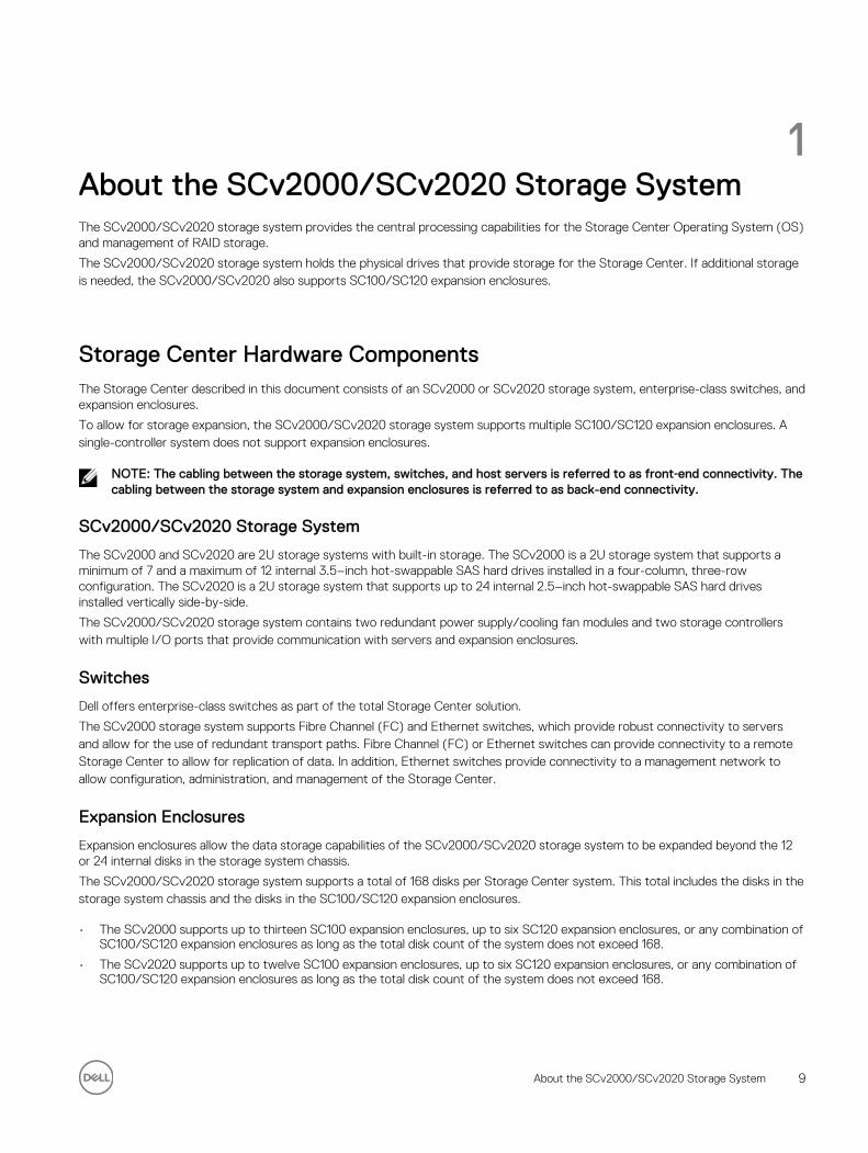
• An SCv2000/SCv2020 storage system deployed without SC100/SC120 expansion enclosures.
Figure 1. SCv2000/SCv2020 without Expansion Enclosures
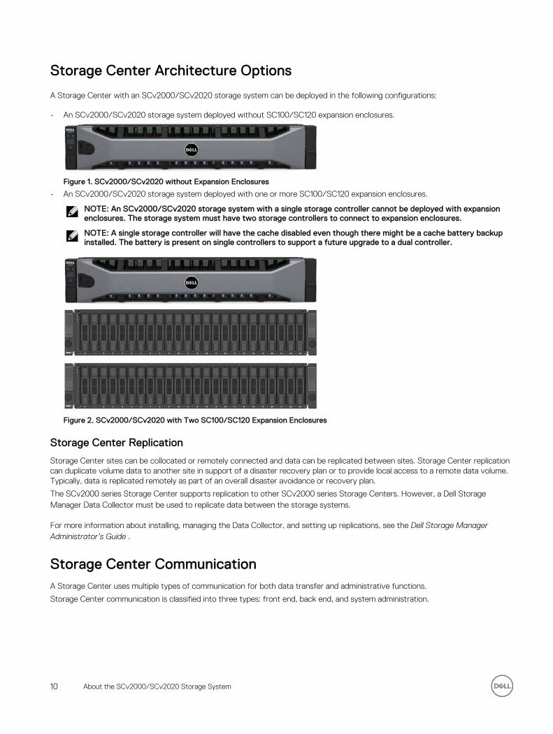
• An SCv2000/SCv2020 storage system deployed with one or more SC100/SC120 expansion enclosures.
NOTE: An SCv2000/SCv2020 storage system with a single storage controller cannot be deployed with expansion enclosures. The storage system must have two storage controllers to connect to expansion enclosures.
NOTE: A single storage controller will have the cache disabled even though there might be a cache battery backup installed. The battery is present on single controllers to support a future upgrade to a dual controller.
Figure 2. SCv2000/SCv2020 with Two SC100/SC120 Expansion Enclosures
Storage Center Replication
Storage Center sites can be collocated or remotely connected and data can be replicated between sites. Storage Center replication can duplicate volume data to another site in support of a disaster recovery plan or to provide local access to a remote data volume. Typically, data is replicated remotely as part of an overall disaster avoidance or recovery plan.
The SCv2000 series Storage Center supports replication to other SCv2000 series Storage Centers. However, a Dell Storage Manager Data Collector must be used to replicate data between the storage systems.
For more information about installing, managing the Data Collector, and setting up replications, see the Dell Storage Manager Administrator’s Guide .
Storage Center CommunicationA Storage Center uses multiple types of communication for both data transfer and administrative functions.
Storage Center communication is classified into three types: front end, back end, and system administration.
10 About the SCv2000/SCv2020 Storage System
Front-End Connectivity
Front-end connectivity provides I/O paths from servers to a storage system and replication paths from one Storage Center to another Storage Center. The SCv2000/SCv2020 storage system provides the following types of front-end connectivity:
• Fibre Channel: Hosts, servers, or Network Attached Storage (NAS) appliances access storage by connecting to the storage system Fibre Channel ports through one or more Fibre Channel switches. Connecting host servers directly to the storage system, without using Fibre Channel switches, is not supported.
When replication is licensed, the SCv2000/SCv2020 can use the front-end Fibre Channel ports to replicate data to another Storage Center.
• iSCSI: Hosts, servers, or Network Attached Storage (NAS) appliances access storage by connecting to the storage system iSCSI ports through one or more Ethernet switches. Connecting host servers directly to the storage system, without using Ethernet switches, is not supported.
When replication is licensed, the SCv2000/SCv2020 can use the front-end iSCSI ports to replicate data to another Storage Center.
• SAS: Hosts or servers access storage by connecting directly to the storage system SAS ports.
NOTE: When replication is licensed, the SCv2000/SCv2020 can use the embedded REPL port to perform iSCSI replication to another SCv2000 series Storage Center.
If replication is licensed and the Flex Port license is installed, the SCv2000/SCv2020 can use the embedded MGMT port to perform iSCSI replication to another SCv2000 series Storage Center. In addition, the SCv2000/SCv2020 can use the embedded MGMT and REPL ports as front-end iSCSI ports for connectivity to host servers when the Flex Port license is installed.
SCv2000/SCv2020 Storage System with Fibre Channel Front-End Connectivity
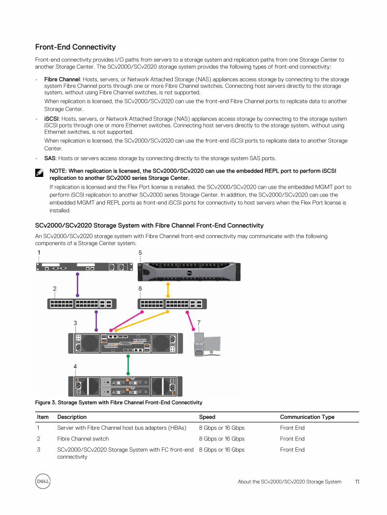
An SCv2000/SCv2020 storage system with Fibre Channel front-end connectivity may communicate with the following components of a Storage Center system.
Figure 3. Storage System with Fibre Channel Front-End Connectivity
Item Description Speed Communication Type
1 Server with Fibre Channel host bus adapters (HBAs) 8 Gbps or 16 Gbps Front End
2 Fibre Channel switch 8 Gbps or 16 Gbps Front End
3 SCv2000/SCv2020 Storage System with FC front-end connectivity
8 Gbps or 16 Gbps Front End
About the SCv2000/SCv2020 Storage System 11
Item Description Speed Communication Type
4 SC100/SC120 Expansion Enclosures 6 Gbps per channel Back End
5 Remote Storage Center connected via iSCSI for replication
1 Gbps or 10 Gbps Front End
6 Ethernet switch 1 Gbps or 10 Gbps (Management/Replication)
Front End
7 Management network (computer connected to the storage system through the Ethernet switch)
Up to 1 Gbps System Administration
SCv2000/SCv2020 Storage System with iSCSI Front-End Connectivity
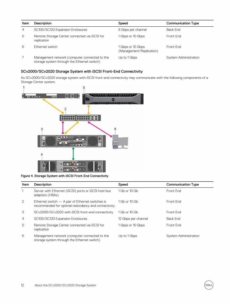
An SCv2000/SCv2020 storage system with iSCSI front-end connectivity may communicate with the following components of a Storage Center system.
Figure 4. Storage System with iSCSI Front-End Connectivity
Item Description Speed Communication Type
1 Server with Ethernet (iSCSI) ports or iSCSI host bus adapters (HBAs)
1 Gb or 10 Gb Front End
2 Ethernet switch — A pair of Ethernet switches is recommended for optimal redundancy and connectivity.
1 Gb or 10 Gb Front End
3 SCv2000/SCv2020 with iSCSI front-end connectivity 1 Gb or 10 Gb Front End
4 SC100/SC120 Expansion Enclosures 12 Gbps per channel Back End
5 Remote Storage Center connected via iSCSI for replication
1 Gbps or 10 Gbps Front End
6 Management network (computer connected to the storage system through the Ethernet switch)
Up to 1 Gbps System Administration
12 About the SCv2000/SCv2020 Storage System
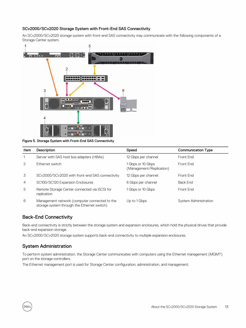
SCv2000/SCv2020 Storage System with Front-End SAS Connectivity
An SCv2000/SCv2020 storage system with front-end SAS connectivity may communicate with the following components of a Storage Center system.
Figure 5. Storage System with Front-End SAS Connectivity
Item Description Speed Communication Type
1 Server with SAS host bus adapters (HBAs) 12 Gbps per channel Front End
2 Ethernet switch 1 Gbps or 10 Gbps (Management/Replication)
Front End
3 SCv2000/SCv2020 with front-end SAS connectivity 12 Gbps per channel Front End
4 SC100/SC120 Expansion Enclosures 6 Gbps per channel Back End
5 Remote Storage Center connected via iSCSI for replication
1 Gbps or 10 Gbps Front End
6 Management network (computer connected to the storage system through the Ethernet switch)
Up to 1 Gbps System Administration
Back-End Connectivity
Back-end connectivity is strictly between the storage system and expansion enclosures, which hold the physical drives that provide back-end expansion storage.
An SCv2000/SCv2020 storage system supports back-end connectivity to multiple expansion enclosures.
System Administration
To perform system administration, the Storage Center communicates with computers using the Ethernet management (MGMT) port on the storage controllers.
The Ethernet management port is used for Storage Center configuration, administration, and management.
About the SCv2000/SCv2020 Storage System 13
SCv2000/SCv2020 Storage System HardwareThe SCv2000/SCv2020 storage system ships with Dell Enterprise drives, two redundant power supply/cooling fan modules, and either one storage controller or two redundant storage controllers.
Each storage controller contains the front-end, back-end, and management communication ports of the storage system.
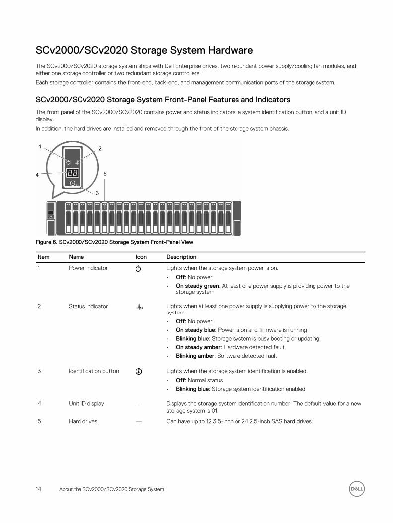
SCv2000/SCv2020 Storage System Front-Panel Features and Indicators
The front panel of the SCv2000/SCv2020 contains power and status indicators, a system identification button, and a unit ID display.
In addition, the hard drives are installed and removed through the front of the storage system chassis.
Figure 6. SCv2000/SCv2020 Storage System Front-Panel View
Item Name Icon Description
1 Power indicator Lights when the storage system power is on.
• Off: No power
• On steady green: At least one power supply is providing power to the storage system
2 Status indicator Lights when at least one power supply is supplying power to the storage system.
• Off: No power
• On steady blue: Power is on and firmware is running
• Blinking blue: Storage system is busy booting or updating
• On steady amber: Hardware detected fault
• Blinking amber: Software detected fault
3 Identification button Lights when the storage system identification is enabled.
• Off: Normal status
• Blinking blue: Storage system identification enabled
4 Unit ID display — Displays the storage system identification number. The default value for a new storage system is 01.
5 Hard drives — Can have up to 12 3.5-inch or 24 2.5-inch SAS hard drives.
14 About the SCv2000/SCv2020 Storage System
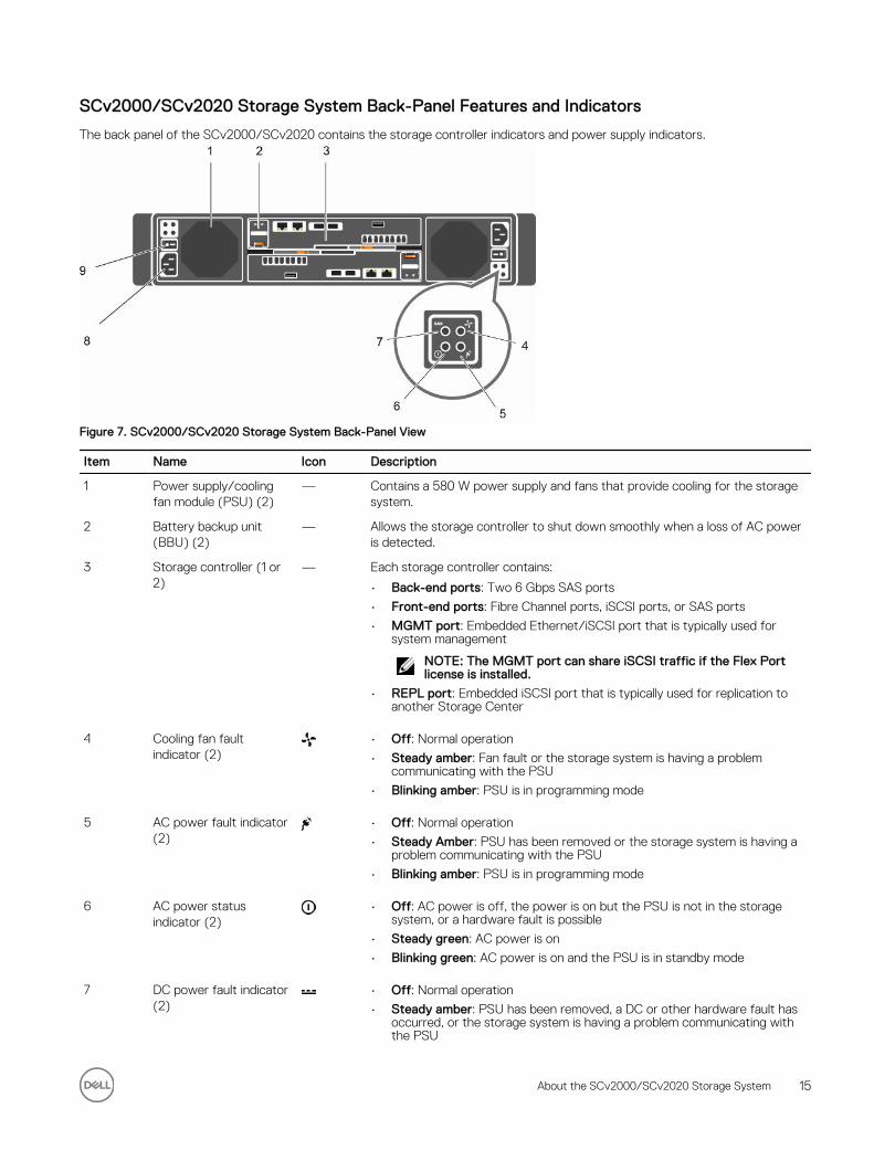
SCv2000/SCv2020 Storage System Back-Panel Features and Indicators
The back panel of the SCv2000/SCv2020 contains the storage controller indicators and power supply indicators.
Figure 7. SCv2000/SCv2020 Storage System Back-Panel View
Item Name Icon Description
1 Power supply/cooling fan module (PSU) (2)
— Contains a 580 W power supply and fans that provide cooling for the storage system.
2 Battery backup unit (BBU) (2)
— Allows the storage controller to shut down smoothly when a loss of AC power is detected.
3 Storage controller (1 or 2)
— Each storage controller contains:
• Back-end ports: Two 6 Gbps SAS ports
• Front-end ports: Fibre Channel ports, iSCSI ports, or SAS ports
• MGMT port: Embedded Ethernet/iSCSI port that is typically used for system management
NOTE: The MGMT port can share iSCSI traffic if the Flex Port license is installed.
• REPL port: Embedded iSCSI port that is typically used for replication to another Storage Center
4 Cooling fan fault indicator (2)
• Off: Normal operation
• Steady amber: Fan fault or the storage system is having a problem communicating with the PSU
• Blinking amber: PSU is in programming mode
5 AC power fault indicator (2)
• Off: Normal operation
• Steady Amber: PSU has been removed or the storage system is having a problem communicating with the PSU
• Blinking amber: PSU is in programming mode
6 AC power status indicator (2)
• Off: AC power is off, the power is on but the PSU is not in the storage system, or a hardware fault is possible
• Steady green: AC power is on
• Blinking green: AC power is on and the PSU is in standby mode
7 DC power fault indicator (2)
• Off: Normal operation
• Steady amber: PSU has been removed, a DC or other hardware fault has occurred, or the storage system is having a problem communicating with the PSU
About the SCv2000/SCv2020 Storage System 15
Item Name Icon Description
• Blinking amber: PSU is in programming mode
8 Power socket (2) — Accepts a standard computer power cord.
9 Power switch (2) — Controls power for the storage system. Each PSU has one switch.
SCv2000/SCv2020 Storage System Storage Controller Features and Indicators
The SCv2000/SCv2020 storage system includes up to two storage controllers in two interface slots.
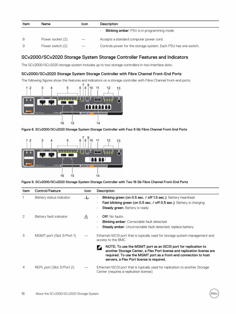
SCv2000/SCv2020 Storage System Storage Controller with Fibre Channel Front-End Ports
The following figures show the features and indicators on a storage controller with Fibre Channel front-end ports.
Figure 8. SCv2000/SCv2020 Storage System Storage Controller with Four 8 Gb Fibre Channel Front-End Ports
Figure 9. SCv2000/SCv2020 Storage System Storage Controller with Two 16 Gb Fibre Channel Front-End Ports
Item Control/Feature Icon Description
1 Battery status indicator • Blinking green (on 0.5 sec. / off 1.5 sec.): Battery heartbeat
• Fast blinking green (on 0.5 sec. / off 0.5 sec.): Battery is charging
• Steady green: Battery is ready
2 Battery fault indicator • Off: No faults
• Blinking amber: Correctable fault detected
• Steady amber: Uncorrectable fault detected; replace battery
3 MGMT port (Slot 3/Port 1) — Ethernet/iSCSI port that is typically used for storage system management and access to the BMC
NOTE: To use the MGMT port as an iSCSI port for replication to another Storage Center, a Flex Port license and replication license are required. To use the MGMT port as a front-end connection to host servers, a Flex Port license is required.
4 REPL port (Slot 3/Port 2) — Ethernet/iSCSI port that is typically used for replication to another Storage Center (requires a replication license)
16 About the SCv2000/SCv2020 Storage System
Item Control/Feature Icon Description
NOTE: To use the RELP port as a front-end connection to host servers, a Flex Port license is required.
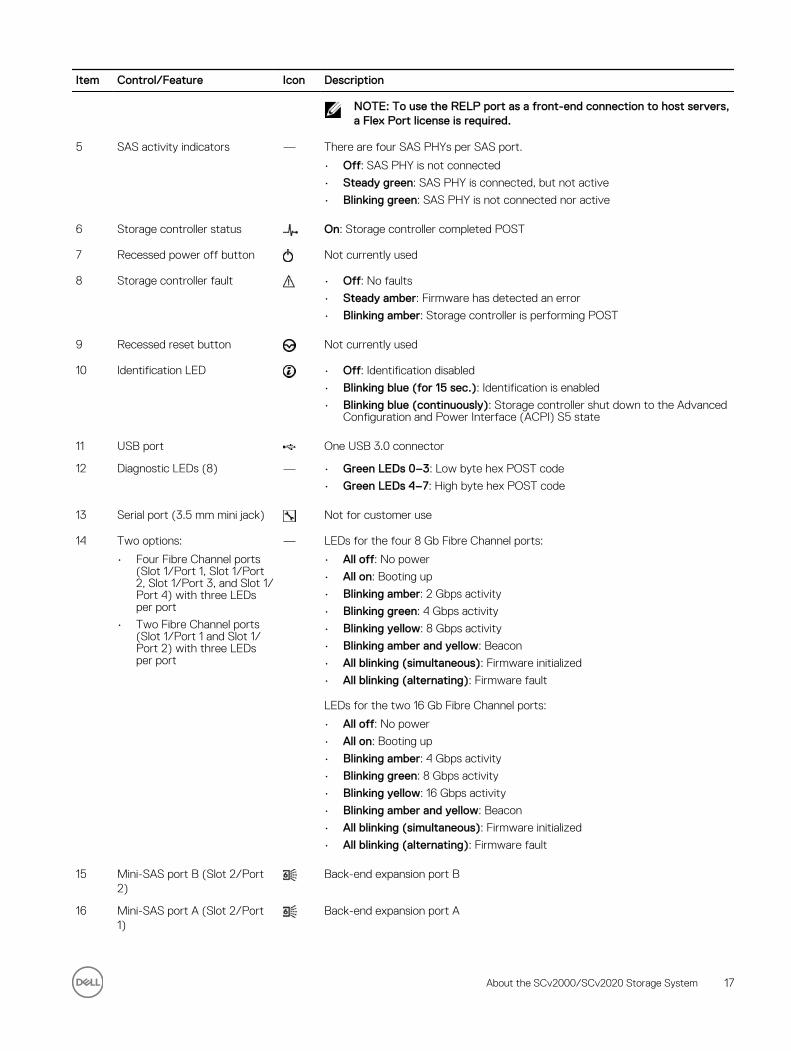
5 SAS activity indicators — There are four SAS PHYs per SAS port.
• Off: SAS PHY is not connected
• Steady green: SAS PHY is connected, but not active
• Blinking green: SAS PHY is not connected nor active
6 Storage controller status On: Storage controller completed POST
7 Recessed power off button Not currently used
8 Storage controller fault • Off: No faults
• Steady amber: Firmware has detected an error
• Blinking amber: Storage controller is performing POST
9 Recessed reset button Not currently used
10 Identification LED • Off: Identification disabled
• Blinking blue (for 15 sec.): Identification is enabled
• Blinking blue (continuously): Storage controller shut down to the Advanced Configuration and Power Interface (ACPI) S5 state
11 USB port One USB 3.0 connector
12 Diagnostic LEDs (8) — • Green LEDs 0–3: Low byte hex POST code
• Green LEDs 4–7: High byte hex POST code
13 Serial port (3.5 mm mini jack) Not for customer use
14 Two options:
• Four Fibre Channel ports (Slot 1/Port 1, Slot 1/Port 2, Slot 1/Port 3, and Slot 1/Port 4) with three LEDs per port
• Two Fibre Channel ports (Slot 1/Port 1 and Slot 1/Port 2) with three LEDs per port
— LEDs for the four 8 Gb Fibre Channel ports:
• All off: No power
• All on: Booting up
• Blinking amber: 2 Gbps activity
• Blinking green: 4 Gbps activity
• Blinking yellow: 8 Gbps activity
• Blinking amber and yellow: Beacon
• All blinking (simultaneous): Firmware initialized
• All blinking (alternating): Firmware fault
LEDs for the two 16 Gb Fibre Channel ports:
• All off: No power
• All on: Booting up
• Blinking amber: 4 Gbps activity
• Blinking green: 8 Gbps activity
• Blinking yellow: 16 Gbps activity
• Blinking amber and yellow: Beacon
• All blinking (simultaneous): Firmware initialized
• All blinking (alternating): Firmware fault
15 Mini-SAS port B (Slot 2/Port 2)
Back-end expansion port B
16 Mini-SAS port A (Slot 2/Port 1)
Back-end expansion port A
About the SCv2000/SCv2020 Storage System 17
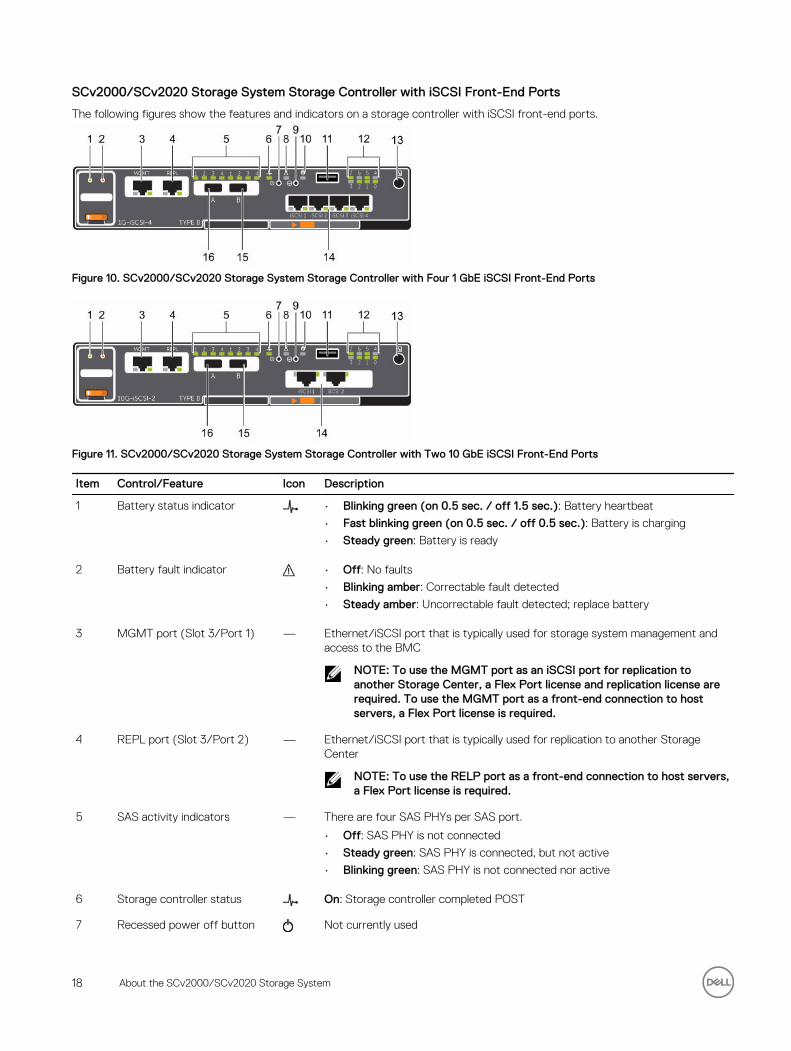
SCv2000/SCv2020 Storage System Storage Controller with iSCSI Front-End Ports
The following figures show the features and indicators on a storage controller with iSCSI front-end ports.
Figure 10. SCv2000/SCv2020 Storage System Storage Controller with Four 1 GbE iSCSI Front-End Ports
Figure 11. SCv2000/SCv2020 Storage System Storage Controller with Two 10 GbE iSCSI Front-End Ports
Item Control/Feature Icon Description
1 Battery status indicator • Blinking green (on 0.5 sec. / off 1.5 sec.): Battery heartbeat
• Fast blinking green (on 0.5 sec. / off 0.5 sec.): Battery is charging
• Steady green: Battery is ready
2 Battery fault indicator • Off: No faults
• Blinking amber: Correctable fault detected
• Steady amber: Uncorrectable fault detected; replace battery
3 MGMT port (Slot 3/Port 1) — Ethernet/iSCSI port that is typically used for storage system management and access to the BMC
NOTE: To use the MGMT port as an iSCSI port for replication to another Storage Center, a Flex Port license and replication license are required. To use the MGMT port as a front-end connection to host servers, a Flex Port license is required.
4 REPL port (Slot 3/Port 2) — Ethernet/iSCSI port that is typically used for replication to another Storage Center
NOTE: To use the RELP port as a front-end connection to host servers, a Flex Port license is required.
5 SAS activity indicators — There are four SAS PHYs per SAS port.
• Off: SAS PHY is not connected
• Steady green: SAS PHY is connected, but not active
• Blinking green: SAS PHY is not connected nor active
6 Storage controller status On: Storage controller completed POST
7 Recessed power off button Not currently used
18 About the SCv2000/SCv2020 Storage System
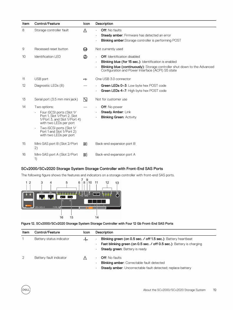
Item Control/Feature Icon Description
8 Storage controller fault • Off: No faults
• Steady amber: Firmware has detected an error
• Blinking amber:Storage controller is performing POST
9 Recessed reset button Not currently used
10 Identification LED • Off: Identification disabled
• Blinking blue (for 15 sec.): Identification is enabled
• Blinking blue (continuously): Storage controller shut down to the Advanced Configuration and Power Interface (ACPI) S5 state
11 USB port One USB 3.0 connector
12 Diagnostic LEDs (8) — • Green LEDs 0–3: Low byte hex POST code
• Green LEDs 4–7: High byte hex POST code
13 Serial port (3.5 mm mini jack) Not for customer use
14 Two options:
• Four iSCSI ports (Slot 1/Port 1, Slot 1/Port 2, Slot 1/Port 3, and Slot 1/Port 4) with two LEDs per port
• Two iSCSI ports (Slot 1/Port 1 and Slot 1/Port 2) with two LEDs per port
— • Off: No power
• Steady Amber: Link
• Blinking Green: Activity
15 Mini-SAS port B (Slot 2/Port 2)
Back-end expansion port B
16 Mini-SAS port A (Slot 2/Port 1)
Back-end expansion port A
SCv2000/SCv2020 Storage System Storage Controller with Front-End SAS Ports
The following figure shows the features and indicators on a storage controller with front-end SAS ports.
Figure 12. SCv2000/SCv2020 Storage System Storage Controller with Four 12 Gb Front-End SAS Ports
Item Control/Feature Icon Description
1 Battery status indicator • Blinking green (on 0.5 sec. / off 1.5 sec.): Battery heartbeat
• Fast blinking green (on 0.5 sec. / off 0.5 sec.): Battery is charging
• Steady green: Battery is ready
2 Battery fault indicator • Off: No faults
• Blinking amber: Correctable fault detected
• Steady amber: Uncorrectable fault detected; replace battery
About the SCv2000/SCv2020 Storage System 19
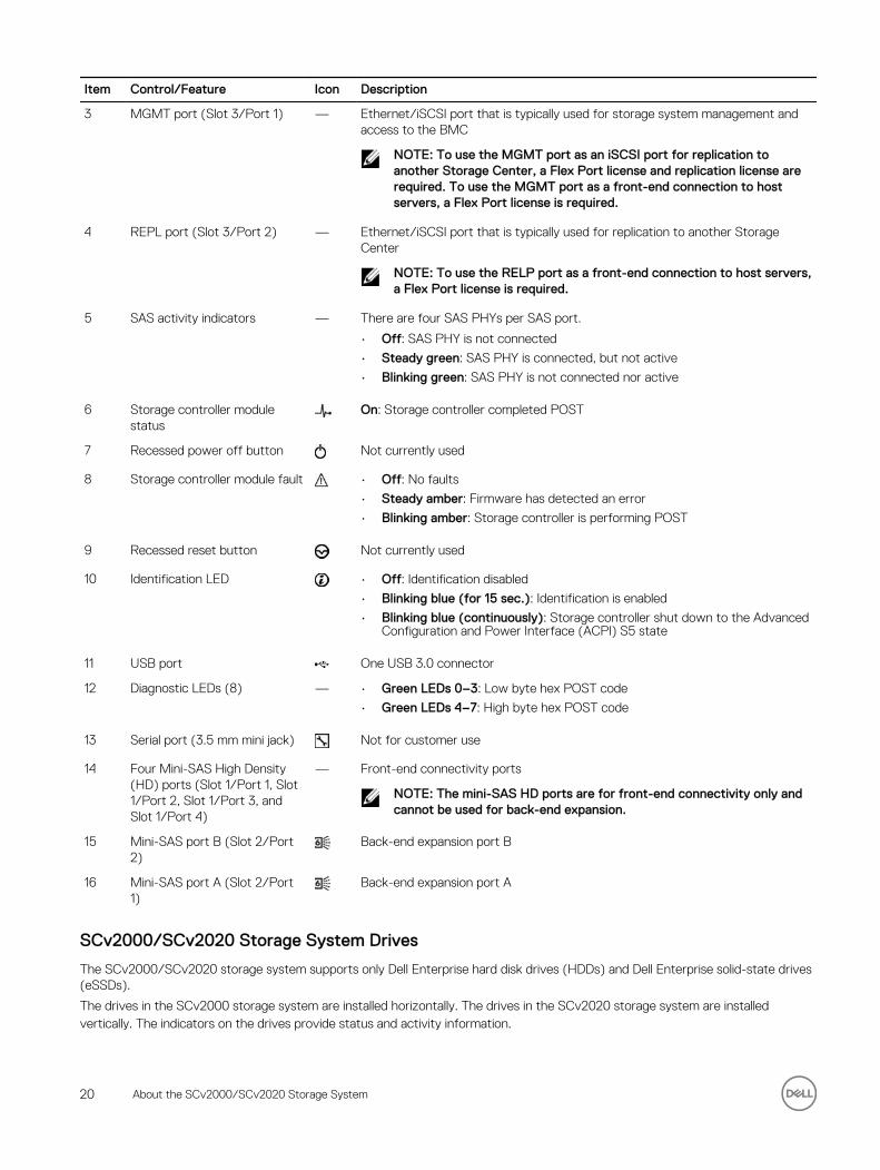
Item Control/Feature Icon Description
3 MGMT port (Slot 3/Port 1) — Ethernet/iSCSI port that is typically used for storage system management and access to the BMC
NOTE: To use the MGMT port as an iSCSI port for replication to another Storage Center, a Flex Port license and replication license are required. To use the MGMT port as a front-end connection to host servers, a Flex Port license is required.
4 REPL port (Slot 3/Port 2) — Ethernet/iSCSI port that is typically used for replication to another Storage Center
NOTE: To use the RELP port as a front-end connection to host servers, a Flex Port license is required.
5 SAS activity indicators — There are four SAS PHYs per SAS port.
• Off: SAS PHY is not connected
• Steady green: SAS PHY is connected, but not active
• Blinking green: SAS PHY is not connected nor active
6 Storage controller module status
On: Storage controller completed POST
7 Recessed power off button Not currently used
8 Storage controller module fault • Off: No faults
• Steady amber: Firmware has detected an error
• Blinking amber: Storage controller is performing POST
9 Recessed reset button Not currently used
10 Identification LED • Off: Identification disabled
• Blinking blue (for 15 sec.): Identification is enabled
• Blinking blue (continuously): Storage controller shut down to the Advanced Configuration and Power Interface (ACPI) S5 state
11 USB port One USB 3.0 connector
12 Diagnostic LEDs (8) — • Green LEDs 0–3: Low byte hex POST code
• Green LEDs 4–7: High byte hex POST code
13 Serial port (3.5 mm mini jack) Not for customer use
14 Four Mini-SAS High Density (HD) ports (Slot 1/Port 1, Slot 1/Port 2, Slot 1/Port 3, and Slot 1/Port 4)
— Front-end connectivity ports
NOTE: The mini-SAS HD ports are for front-end connectivity only and cannot be used for back-end expansion.
15 Mini-SAS port B (Slot 2/Port 2)
Back-end expansion port B
16 Mini-SAS port A (Slot 2/Port 1)
Back-end expansion port A
SCv2000/SCv2020 Storage System Drives
The SCv2000/SCv2020 storage system supports only Dell Enterprise hard disk drives (HDDs) and Dell Enterprise solid-state drives (eSSDs).
The drives in the SCv2000 storage system are installed horizontally. The drives in the SCv2020 storage system are installed vertically. The indicators on the drives provide status and activity information.
20 About the SCv2000/SCv2020 Storage System
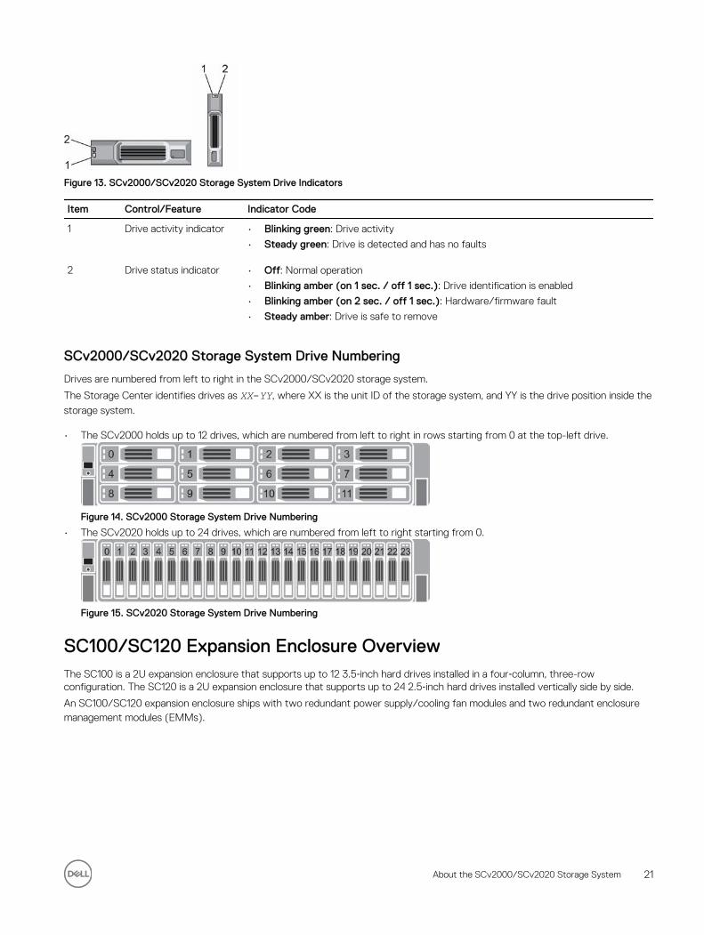
Figure 13. SCv2000/SCv2020 Storage System Drive Indicators
Item Control/Feature Indicator Code
1 Drive activity indicator • Blinking green: Drive activity
• Steady green: Drive is detected and has no faults
2 Drive status indicator • Off: Normal operation
• Blinking amber (on 1 sec. / off 1 sec.): Drive identification is enabled
• Blinking amber (on 2 sec. / off 1 sec.): Hardware/firmware fault
• Steady amber: Drive is safe to remove
SCv2000/SCv2020 Storage System Drive Numbering
Drives are numbered from left to right in the SCv2000/SCv2020 storage system.
The Storage Center identifies drives as XX-YY, where XX is the unit ID of the storage system, and YY is the drive position inside the
storage system.
• The SCv2000 holds up to 12 drives, which are numbered from left to right in rows starting from 0 at the top-left drive.
Figure 14. SCv2000 Storage System Drive Numbering
• The SCv2020 holds up to 24 drives, which are numbered from left to right starting from 0.
Figure 15. SCv2020 Storage System Drive Numbering
SC100/SC120 Expansion Enclosure OverviewThe SC100 is a 2U expansion enclosure that supports up to 12 3.5‐inch hard drives installed in a four‐column, three-row configuration. The SC120 is a 2U expansion enclosure that supports up to 24 2.5‐inch hard drives installed vertically side by side.
An SC100/SC120 expansion enclosure ships with two redundant power supply/cooling fan modules and two redundant enclosure management modules (EMMs).
About the SCv2000/SCv2020 Storage System 21
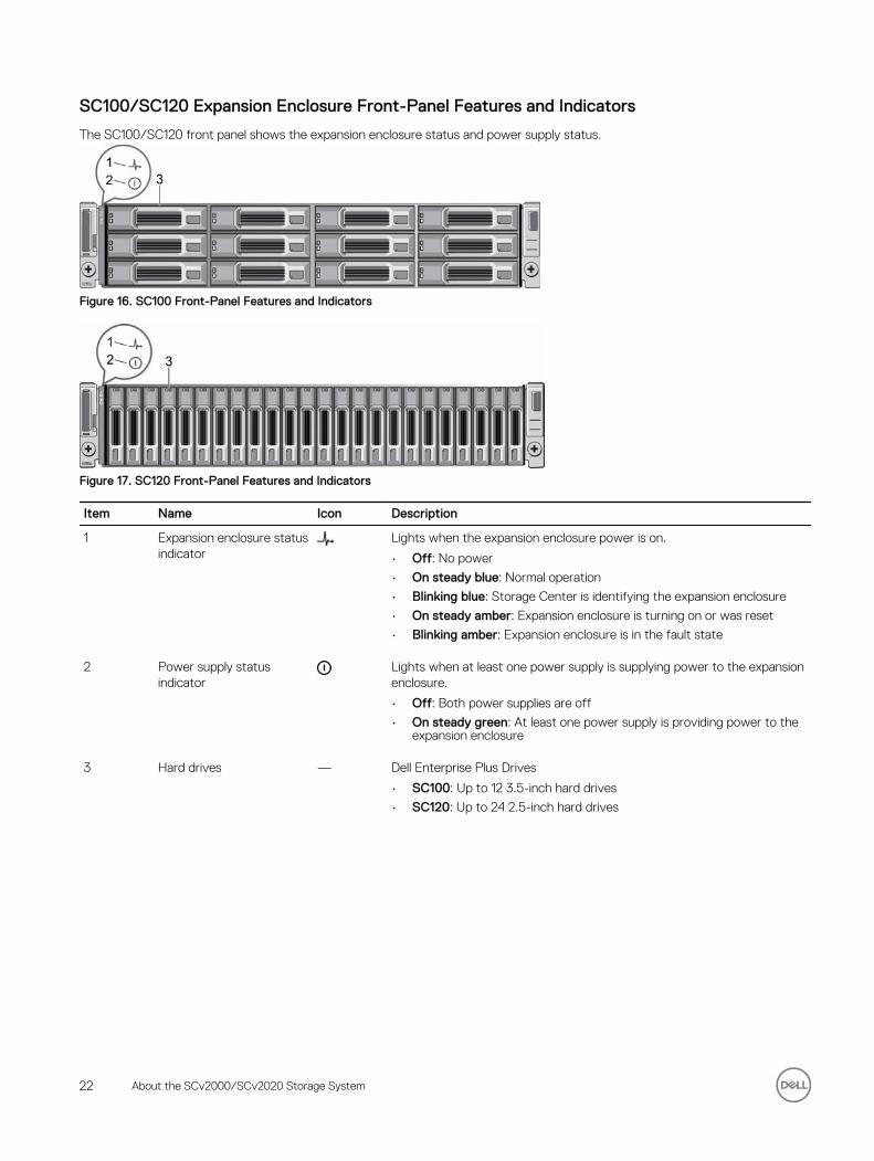
SC100/SC120 Expansion Enclosure Front-Panel Features and Indicators
The SC100/SC120 front panel shows the expansion enclosure status and power supply status.
Figure 16. SC100 Front-Panel Features and Indicators
Figure 17. SC120 Front-Panel Features and Indicators
Item Name Icon Description
1 Expansion enclosure status indicator
Lights when the expansion enclosure power is on.
• Off: No power
• On steady blue: Normal operation
• Blinking blue: Storage Center is identifying the expansion enclosure
• On steady amber: Expansion enclosure is turning on or was reset
• Blinking amber: Expansion enclosure is in the fault state
2 Power supply status indicator
Lights when at least one power supply is supplying power to the expansion enclosure.
• Off: Both power supplies are off
• On steady green: At least one power supply is providing power to the expansion enclosure
3 Hard drives — Dell Enterprise Plus Drives
• SC100: Up to 12 3.5-inch hard drives
• SC120: Up to 24 2.5-inch hard drives
22 About the SCv2000/SCv2020 Storage System
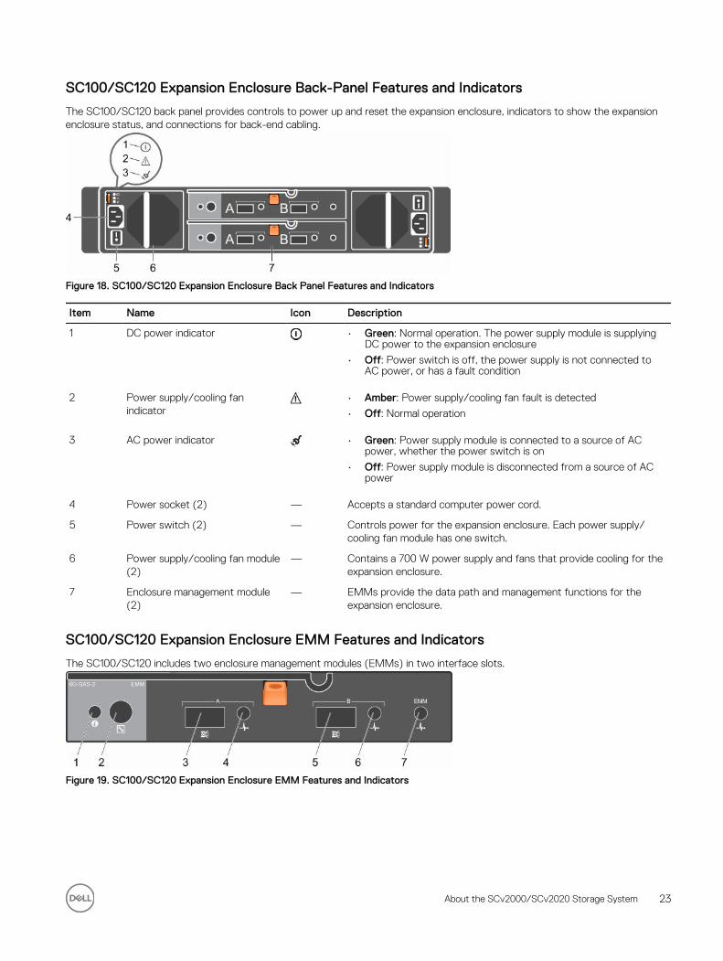
SC100/SC120 Expansion Enclosure Back-Panel Features and Indicators
The SC100/SC120 back panel provides controls to power up and reset the expansion enclosure, indicators to show the expansion enclosure status, and connections for back-end cabling.
Figure 18. SC100/SC120 Expansion Enclosure Back Panel Features and Indicators
Item Name Icon Description
1 DC power indicator • Green: Normal operation. The power supply module is supplying DC power to the expansion enclosure
• Off: Power switch is off, the power supply is not connected to AC power, or has a fault condition
2 Power supply/cooling fan indicator
• Amber: Power supply/cooling fan fault is detected
• Off: Normal operation
3 AC power indicator • Green: Power supply module is connected to a source of AC power, whether the power switch is on
• Off: Power supply module is disconnected from a source of AC power
4 Power socket (2) — Accepts a standard computer power cord.
5 Power switch (2) — Controls power for the expansion enclosure. Each power supply/cooling fan module has one switch.
6 Power supply/cooling fan module (2)
— Contains a 700 W power supply and fans that provide cooling for the expansion enclosure.
7 Enclosure management module (2)
— EMMs provide the data path and management functions for the expansion enclosure.
SC100/SC120 Expansion Enclosure EMM Features and Indicators
The SC100/SC120 includes two enclosure management modules (EMMs) in two interface slots.
Figure 19. SC100/SC120 Expansion Enclosure EMM Features and Indicators
About the SCv2000/SCv2020 Storage System 23
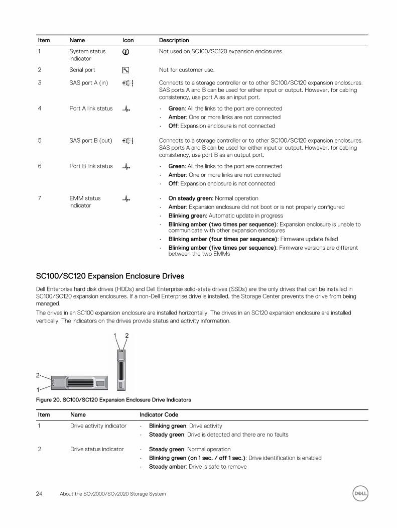
Item Name Icon Description
1 System status indicator
Not used on SC100/SC120 expansion enclosures.
2 Serial port Not for customer use.
3 SAS port A (in) Connects to a storage controller or to other SC100/SC120 expansion enclosures. SAS ports A and B can be used for either input or output. However, for cabling consistency, use port A as an input port.
4 Port A link status • Green: All the links to the port are connected
• Amber: One or more links are not connected
• Off: Expansion enclosure is not connected
5 SAS port B (out) Connects to a storage controller or to other SC100/SC120 expansion enclosures. SAS ports A and B can be used for either input or output. However, for cabling consistency, use port B as an output port.
6 Port B link status • Green: All the links to the port are connected
• Amber: One or more links are not connected
• Off: Expansion enclosure is not connected
7 EMM status indicator
• On steady green: Normal operation
• Amber: Expansion enclosure did not boot or is not properly configured
• Blinking green: Automatic update in progress
• Blinking amber (two times per sequence): Expansion enclosure is unable to communicate with other expansion enclosures
• Blinking amber (four times per sequence): Firmware update failed
• Blinking amber (five times per sequence): Firmware versions are different between the two EMMs
SC100/SC120 Expansion Enclosure Drives
Dell Enterprise hard disk drives (HDDs) and Dell Enterprise solid-state drives (SSDs) are the only drives that can be installed in SC100/SC120 expansion enclosures. If a non-Dell Enterprise drive is installed, the Storage Center prevents the drive from being managed.
The drives in an SC100 expansion enclosure are installed horizontally. The drives in an SC120 expansion enclosure are installed vertically. The indicators on the drives provide status and activity information.
Figure 20. SC100/SC120 Expansion Enclosure Drive Indicators
Item Name Indicator Code
1 Drive activity indicator • Blinking green: Drive activity
• Steady green: Drive is detected and there are no faults
2 Drive status indicator • Steady green: Normal operation
• Blinking green (on 1 sec. / off 1 sec.): Drive identification is enabled
• Steady amber: Drive is safe to remove
24 About the SCv2000/SCv2020 Storage System
Item Name Indicator Code
• Off: No power to the drive
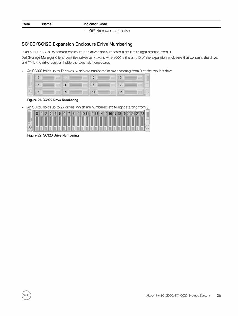
SC100/SC120 Expansion Enclosure Drive Numbering
In an SC100/SC120 expansion enclosure, the drives are numbered from left to right starting from 0.
Dell Storage Manager Client identifies drives as XX-YY, where XX is the unit ID of the expansion enclosure that contains the drive,
and YY is the drive position inside the expansion enclosure.
• An SC100 holds up to 12 drives, which are numbered in rows starting from 0 at the top-left drive.
Figure 21. SC100 Drive Numbering
• An SC120 holds up to 24 drives, which are numbered left to right starting from 0.
Figure 22. SC120 Drive Numbering
About the SCv2000/SCv2020 Storage System 25
2Install the Storage Center HardwareThis section describes how to unpack the Storage Center equipment, prepare for the installation, and mount the equipment in a rack.
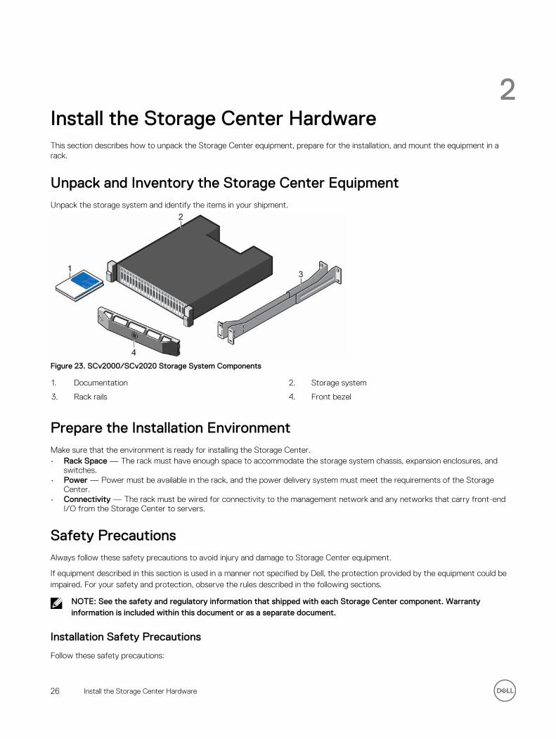
Unpack and Inventory the Storage Center EquipmentUnpack the storage system and identify the items in your shipment.
Figure 23. SCv2000/SCv2020 Storage System Components
1. Documentation 2. Storage system
3. Rack rails 4. Front bezel
Prepare the Installation EnvironmentMake sure that the environment is ready for installing the Storage Center.• Rack Space — The rack must have enough space to accommodate the storage system chassis, expansion enclosures, and
switches.• Power — Power must be available in the rack, and the power delivery system must meet the requirements of the Storage
Center.• Connectivity — The rack must be wired for connectivity to the management network and any networks that carry front-end
I/O from the Storage Center to servers.
Safety PrecautionsAlways follow these safety precautions to avoid injury and damage to Storage Center equipment.
If equipment described in this section is used in a manner not specified by Dell, the protection provided by the equipment could be impaired. For your safety and protection, observe the rules described in the following sections.
NOTE: See the safety and regulatory information that shipped with each Storage Center component. Warranty information is included within this document or as a separate document.
Installation Safety Precautions
Follow these safety precautions:
26 Install the Storage Center Hardware
• Dell recommends that only individuals with rack-mounting experience install the SCv2000/SCv2020 in a rack.
• Make sure the storage system is always fully grounded to prevent damage from electrostatic discharge.
• When handling the storage system hardware, use an electrostatic wrist guard (not included) or a similar form of protection.
The chassis must be mounted in a rack. The following safety requirements must be considered when the chassis is being mounted:
• The rack construction must be capable of supporting the total weight of the installed chassis. The design should incorporate stabilizing features suitable to prevent the rack from tipping or being pushed over during installation or in normal use.
• To avoid danger of the rack toppling over, slide only one chassis out of the rack at a time.
Electrical Safety Precautions
Always follow electrical safety precautions to avoid injury and damage to Storage Center equipment.
WARNING: Disconnect power from the storage system when removing or installing components that are not hot-swappable. When disconnecting power, first power down the storage system using the storage client and then unplug the power cords from the power supplies in the storage system and storage system.
• Provide a suitable power source with electrical overload protection. All Storage Center components must be grounded before applying power. Make sure that a safe electrical earth connection can be made to power supply cords. Check the grounding before applying power.
• The plugs on the power supply cords are used as the main disconnect device. Make sure that the socket outlets are located near the equipment and are easily accessible.
• Know the locations of the equipment power switches and the room's emergency power-off switch, disconnection switch, or electrical outlet.
• Do not work alone when working with high-voltage components.
• Use rubber mats specifically designed as electrical insulators.
• Do not remove covers from the power supply unit. Disconnect the power connection before removing a power supply from the storage system.
• Do not remove a faulty power supply unless you have a replacement model of the correct type ready for insertion. A faulty power supply must be replaced with a fully operational module power supply within 24 hours.
• Unplug the storage system chassis before you move it or if you think it has become damaged in any way. When powered by multiple AC sources, disconnect all power sources for complete isolation.
Electrostatic Discharge Precautions
Always follow electrostatic discharge (ESD) precautions to avoid injury and damage to Storage Center equipment.
Electrostatic discharge (ESD) is generated by two objects with different electrical charges coming into contact with each other. The resulting electrical discharge can damage electronic components and printed circuit boards. Follow these guidelines to protect your equipment from ESD:
• Dell recommends that you always use a static mat and static strap while working on components in the interior of the storage system chassis.
• Observe all conventional ESD precautions when handling plug-in modules and components.
• Use a suitable ESD wrist or ankle strap.
• Avoid contact with backplane components and module connectors.
• Keep all components and printed circuit boards (PCBs) in their antistatic bags until ready for use.
General Safety Precautions
Always follow general safety precautions to avoid injury and damage to Storage Center equipment.
• Keep the area around the storage system chassis clean and free of clutter.
• Place any system components that have been removed away from the storage system chassis or on a table so that they are not in the way of other people.
• While working on the storage system chassis, do not wear loose clothing such as neckties and unbuttoned shirt sleeves. These items can come into contact with electrical circuits or be pulled into a cooling fan.
Install the Storage Center Hardware 27
• Remove any jewelry or metal objects from your body. These items are excellent metal conductors that can create short circuits and harm you if they come into contact with printed circuit boards or areas where power is present.
• Do not lift the storage system chassis by the handles of the power supply units (PSUs). They are not designed to hold the weight of the entire chassis, and the chassis cover could become bent.
• Before moving the storage system chassis, remove the PSUs to minimize weight.
• Do not remove drives until you are ready to replace them.
NOTE: To ensure proper storage system cooling, hard drive blanks must be installed in any hard drive slot that is not occupied.
Install the Storage System in a RackInstall the storage system and other Storage Center system components in a rack.
About this task
Mount the storage system and expansion enclosures in a manner that allows for expansion in the rack and prevents the rack from becoming top‐heavy.
NOTE: Because the depth of the storage system is only 54.68 cm (21.53 in.), do not mount it below a piece of equipment with a full depth chassis. Instead, mount the storage system in a location from which you can access the rear of the storage system.
Steps
1. Secure the rails that are attached to both sides of the storage system chassis.
a. Lift the locking tab on the rail.b. Push the rail toward the back of the chassis until it locks in place.
2. Determine where to mount the storage system and mark the location at the front and back of the rack.
NOTE: The storage system and expansion enclosures each require 2U of rack space for installation.
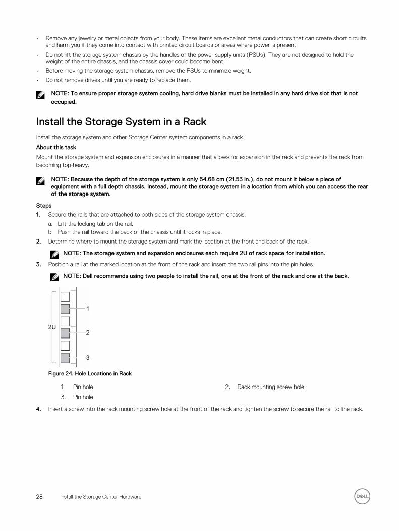
3. Position a rail at the marked location at the front of the rack and insert the two rail pins into the pin holes.
NOTE: Dell recommends using two people to install the rail, one at the front of the rack and one at the back.
Figure 24. Hole Locations in Rack
1. Pin hole 2. Rack mounting screw hole
3. Pin hole
4. Insert a screw into the rack mounting screw hole at the front of the rack and tighten the screw to secure the rail to the rack.
28 Install the Storage Center Hardware
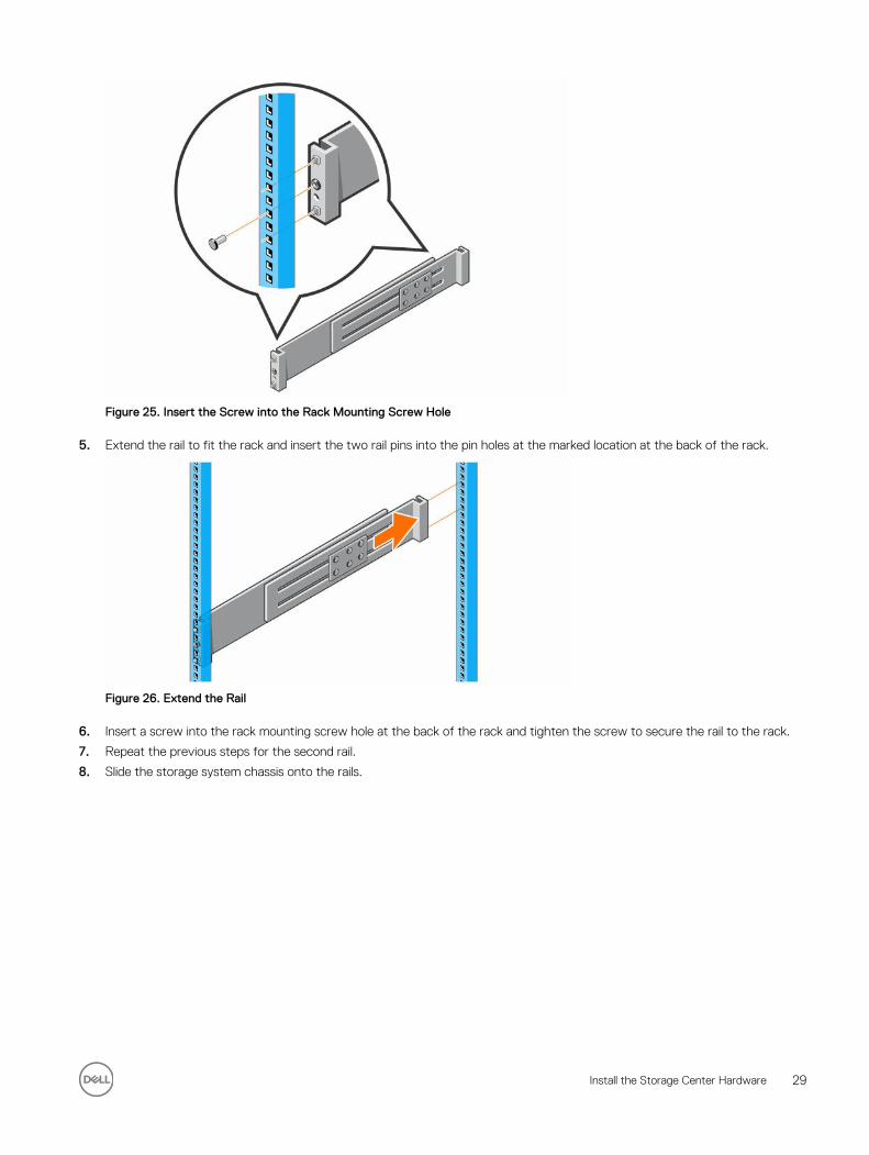
Figure 25. Insert the Screw into the Rack Mounting Screw Hole
5. Extend the rail to fit the rack and insert the two rail pins into the pin holes at the marked location at the back of the rack.
Figure 26. Extend the Rail
6. Insert a screw into the rack mounting screw hole at the back of the rack and tighten the screw to secure the rail to the rack.
7. Repeat the previous steps for the second rail.
8. Slide the storage system chassis onto the rails.
Install the Storage Center Hardware 29
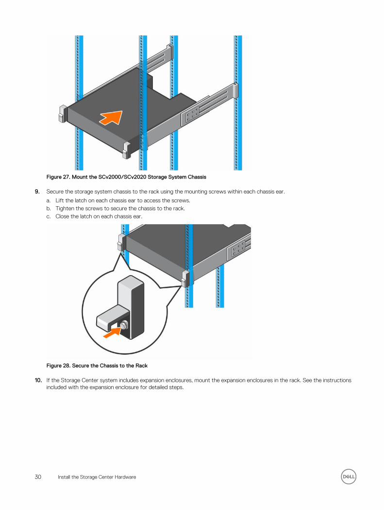
Figure 27. Mount the SCv2000/SCv2020 Storage System Chassis
9. Secure the storage system chassis to the rack using the mounting screws within each chassis ear.
a. Lift the latch on each chassis ear to access the screws.b. Tighten the screws to secure the chassis to the rack.c. Close the latch on each chassis ear.
Figure 28. Secure the Chassis to the Rack
10. If the Storage Center system includes expansion enclosures, mount the expansion enclosures in the rack. See the instructions included with the expansion enclosure for detailed steps.
30 Install the Storage Center Hardware
3Connect the Front-End CablingFront-end cabling refers to the connections between the storage system and external devices such as host servers or another Storage Center.
Front‐end connections can be made using Fibre Channel, iSCSI, or SAS interfaces. Dell recommends connecting the storage system to host servers using the most redundant option available.
Types of Redundancy for Front-End ConnectionsFront-end redundancy is achieved by eliminating single points of failure that could cause a server to lose connectivity to the Storage Center.
Depending on how the Storage Center is cabled and configured, the following types of redundancy are available.
Table 1. Redundancy and Failover Behavior
Redundancy Failover Behavior
Asymmetric Logical Unit Access (ALUA)
If a storage controller becomes unavailable, all the standby paths on the other storage controller become active.
Port redundancy If a single port becomes unavailable, the port can move to another available port in the same fault domain.
Storage controller redundancy If a storage controller becomes unavailable, the ports on the offline storage controller can move to the available storage controller.
Path redundancy When multiple paths are available from a server to a storage system, a server configured for multipath I/O (MPIO) can use multiple paths for I/O. If a path becomes unavailable, the server continues to use the remaining available paths.
Port Redundancy
To allow for port redundancy, two front-end ports on a storage controller must be connected to the same switch or server.
Fault domains group front-end ports that are connected to the same network. Ports that belong to the same fault domain can fail over to each other because they have the same connectivity.
If a port becomes unavailable because it is disconnected or a hardware failure has occurred, the port moves over to another port in the same fault domain.
Storage Controller Redundancy
To allow for storage controller redundancy, a front-end port on each storage controller must be connected to the same switch or server.
If a storage controller becomes unavailable, the front-end ports on the offline storage controller move over to the ports (in the same fault domain) on the available storage controller.
Connect the Front-End Cabling 31
Multipath I/O
MPIO allows a server to use multiple paths for I/O if they are available.
MPIO software offers redundancy at the path level. MPIO typically operates in a round-robin manner by sending packets first down one path and then the other. If a path becomes unavailable, MPIO software continues to send packets down the functioning path. MPIO is required to enable redundancy for servers connected to a Storage Center with SAS front-end connectivity.
NOTE: MPIO is operating-system specific, and it loads as a driver on the server or it is part of the server operating system.
MPIO Behavior
The server must have at least two FC, iSCSI, or SAS ports to use MPIO.
When MPIO is configured, a server can send I/O to multiple ports on the same storage controller.
MPIO Configuration Instructions for Host Servers
To use MPIO, configure MPIO on the host server.
If a Dell Storage Manager Client wizard is used to configure host server access to the Storage Center, the Dell Storage Manager Client attempts to automatically configure MPIO with best practices.
NOTE: Compare the host server settings applied by the Dell Storage Manager Client wizard against the latest Dell Storage Center Best Practices document on the Dell TechCenter site (http://en.community.dell.com/techcenter/storage/). .
Table 2. MPIO Configuration Documents
Operating System Document with MPIO Instructions
Linux • Dell Storage Center with Red Hat Enterprise Linux (RHEL) 6x Best Practices
• Dell Storage Center with Red Hat Enterprise Linux (RHEL) 7x Best Practices
• Dell Compellent Best Practices: Storage Center with SUSE Linux Enterprise Server 11
VMware vSphere 5.x • Dell Storage Center Best Practices with VMware vSphere 5.x
• Dell Storage Center Best Practices with VMware vSphere 6.x
Windows Server 2008, 2008 R2, 2012, and 2012 R2
Dell Storage Center: Microsoft Multipath I/O Best Practices
Cabling SAN-Attached Host ServersAn SCv2000/SCv2020 storage system with Fibre Channel or iSCSI front-end ports connects to host servers through Fibre Channel or Ethernet switches.
• A storage system with Fibre Channel front-end ports connects to one or more FC switches, which connect to one or more host servers.
• A storage system with iSCSI front-end ports connects to one or more Ethernet switches, which connect to one or more host servers.
Connecting to Fibre Channel Host Servers
Choose the Fibre Channel connectivity option that best suits the front‐end redundancy requirements and network infrastructure.
Preparing Host Servers
Install the Fibre Channel host bus adapters (HBAs), install the drivers, and make sure that the latest supported firmware is installed.
About this task
• Contact your solution provider for a list of supported Fibre Channel HBAs.
32 Connect the Front-End Cabling
• Refer to the Dell Storage Compatibility Matrix for a list of supported Fibre Channel HBAs.
Steps
1. Install Fibre Channel HBAs in the host servers.
NOTE: Do not install Fibre Channel HBAs from different vendors in the same server.
2. Install supported drivers for the HBAs and make sure that the HBAs have the latest supported firmware.
3. Use the Fibre Channel cabling diagrams to cable the host servers to the switches. Connecting host servers directly to the storage system without using Fibre Channel switches is not supported.
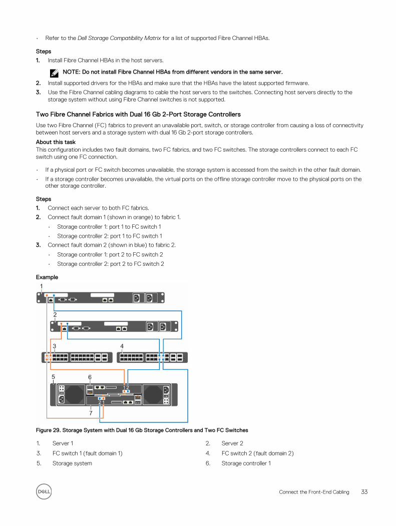
Two Fibre Channel Fabrics with Dual 16 Gb 2-Port Storage Controllers
Use two Fibre Channel (FC) fabrics to prevent an unavailable port, switch, or storage controller from causing a loss of connectivity between host servers and a storage system with dual 16 Gb 2-port storage controllers.
About this taskThis configuration includes two fault domains, two FC fabrics, and two FC switches. The storage controllers connect to each FC switch using one FC connection.
• If a physical port or FC switch becomes unavailable, the storage system is accessed from the switch in the other fault domain.
• If a storage controller becomes unavailable, the virtual ports on the offline storage controller move to the physical ports on the other storage controller.
Steps
1. Connect each server to both FC fabrics.
2. Connect fault domain 1 (shown in orange) to fabric 1.
• Storage controller 1: port 1 to FC switch 1
• Storage controller 2: port 1 to FC switch 1
3. Connect fault domain 2 (shown in blue) to fabric 2.
• Storage controller 1: port 2 to FC switch 2
• Storage controller 2: port 2 to FC switch 2
Example
Figure 29. Storage System with Dual 16 Gb Storage Controllers and Two FC Switches
1. Server 1 2. Server 2
3. FC switch 1 (fault domain 1) 4. FC switch 2 (fault domain 2)
5. Storage system 6. Storage controller 1
Connect the Front-End Cabling 33
7. Storage controller 2
Next stepsInstall or enable MPIO on the host servers.
NOTE: After the Storage Center configuration is complete, run the host access wizard to configure host server access and apply MPIO best practices. For the latest best practices, see the Dell Storage Center Best Practices document on the Dell TechCenter site (http://en.community.dell.com/techcenter/storage/).
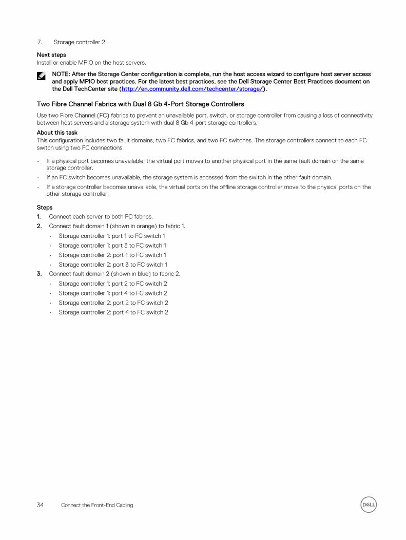
Two Fibre Channel Fabrics with Dual 8 Gb 4-Port Storage Controllers
Use two Fibre Channel (FC) fabrics to prevent an unavailable port, switch, or storage controller from causing a loss of connectivity between host servers and a storage system with dual 8 Gb 4-port storage controllers.
About this taskThis configuration includes two fault domains, two FC fabrics, and two FC switches. The storage controllers connect to each FC switch using two FC connections.
• If a physical port becomes unavailable, the virtual port moves to another physical port in the same fault domain on the same storage controller.
• If an FC switch becomes unavailable, the storage system is accessed from the switch in the other fault domain.
• If a storage controller becomes unavailable, the virtual ports on the offline storage controller move to the physical ports on the other storage controller.
Steps
1. Connect each server to both FC fabrics.
2. Connect fault domain 1 (shown in orange) to fabric 1.
• Storage controller 1: port 1 to FC switch 1
• Storage controller 1: port 3 to FC switch 1
• Storage controller 2: port 1 to FC switch 1
• Storage controller 2: port 3 to FC switch 1
3. Connect fault domain 2 (shown in blue) to fabric 2.
• Storage controller 1: port 2 to FC switch 2
• Storage controller 1: port 4 to FC switch 2
• Storage controller 2: port 2 to FC switch 2
• Storage controller 2: port 4 to FC switch 2
34 Connect the Front-End Cabling
Example
Figure 30. Storage System with Dual 8 Gb Storage Controllers and Two FC Switches
1. Server 1 2. Server 2
3. FC switch 1 (fault domain 1) 4. FC switch 2 (fault domain 2)
5. Storage system 6. Storage controller 1
7. Storage controller 2
Next stepsInstall or enable MPIO on the host servers.
NOTE: After the Storage Center configuration is complete, run the host access wizard to configure host server access and apply MPIO best practices. For the latest best practices, see the Dell Storage Center Best Practices document on the Dell TechCenter site (http://en.community.dell.com/techcenter/storage/).
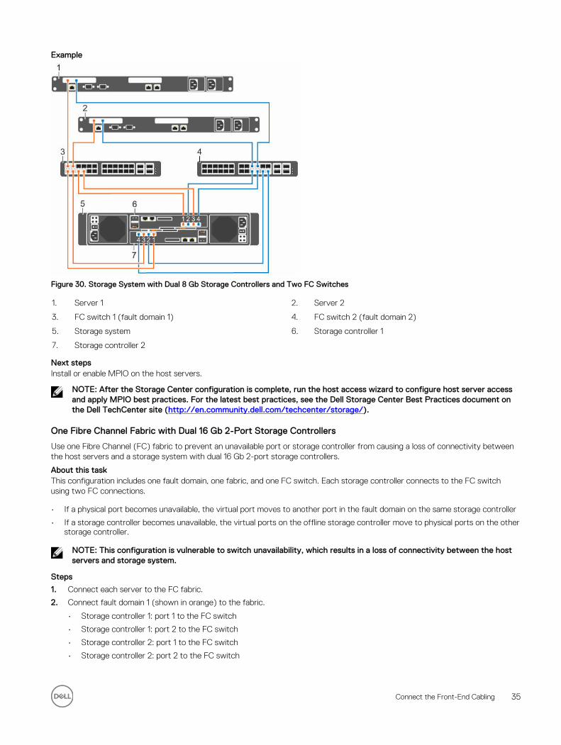
One Fibre Channel Fabric with Dual 16 Gb 2-Port Storage Controllers
Use one Fibre Channel (FC) fabric to prevent an unavailable port or storage controller from causing a loss of connectivity between the host servers and a storage system with dual 16 Gb 2-port storage controllers.
About this taskThis configuration includes one fault domain, one fabric, and one FC switch. Each storage controller connects to the FC switch using two FC connections.
• If a physical port becomes unavailable, the virtual port moves to another port in the fault domain on the same storage controller
• If a storage controller becomes unavailable, the virtual ports on the offline storage controller move to physical ports on the other storage controller.
NOTE: This configuration is vulnerable to switch unavailability, which results in a loss of connectivity between the host servers and storage system.
Steps
1. Connect each server to the FC fabric.
2. Connect fault domain 1 (shown in orange) to the fabric.
• Storage controller 1: port 1 to the FC switch
• Storage controller 1: port 2 to the FC switch
• Storage controller 2: port 1 to the FC switch
• Storage controller 2: port 2 to the FC switch
Connect the Front-End Cabling 35
Example
Figure 31. Storage System with Dual 16 Gb Storage Controllers and One FC Switch
1. Server 1 2. Server 2
3. FC switch (Fault domain 1) 4. Storage system
5. Storage controller 1 6. Storage controller 2
Next stepsInstall or enable MPIO on the host servers.
NOTE: After the Storage Center configuration is complete, run the host access wizard to configure host server access and apply MPIO best practices. For the latest best practices, see the Dell Storage Center Best Practices document on the Dell TechCenter site (http://en.community.dell.com/techcenter/storage/).
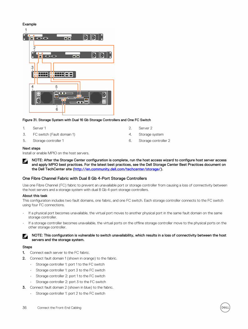
One Fibre Channel Fabric with Dual 8 Gb 4-Port Storage Controllers
Use one Fibre Channel (FC) fabric to prevent an unavailable port or storage controller from causing a loss of connectivity between the host servers and a storage system with dual 8 Gb 4-port storage controllers.
About this taskThis configuration includes two fault domains, one fabric, and one FC switch. Each storage controller connects to the FC switch using four FC connections.
• If a physical port becomes unavailable, the virtual port moves to another physical port in the same fault domain on the same storage controller.
• If a storage controller becomes unavailable, the virtual ports on the offline storage controller move to the physical ports on the other storage controller.
NOTE: This configuration is vulnerable to switch unavailability, which results in a loss of connectivity between the host servers and the storage system.
Steps
1. Connect each server to the FC fabric.
2. Connect fault domain 1 (shown in orange) to the fabric.
• Storage controller 1: port 1 to the FC switch
• Storage controller 1: port 3 to the FC switch
• Storage controller 2: port 1 to the FC switch
• Storage controller 2: port 3 to the FC switch
3. Connect fault domain 2 (shown in blue) to the fabric.
• Storage controller 1: port 2 to the FC switch
36 Connect the Front-End Cabling

• Storage controller 1: port 4 to the FC switch
• Storage controller 2: port 2 to the FC switch
• Storage controller 2: port 4 to the FC switch
Example
Figure 32. Storage System with Dual 8 Gb Storage Controllers and One FC Switch
1. Server 1 2. Server 2
3. FC switch (fault domain 1 and fault domain 2) 4. Storage system
5. Storage controller 1 6. Storage controller 2
Next stepsInstall or enable MPIO on the host servers.
NOTE: After the Storage Center configuration is complete, run the host access wizard to configure host server access and apply MPIO best practices. For the latest best practices, see the Dell Storage Center Best Practices document on the Dell TechCenter site (http://en.community.dell.com/techcenter/storage/).
Two Fibre Channel Fabrics with a Single 16 Gb 2-Port Storage Controller
Use two Fibre Channel (FC) fabrics to prevent an unavailable port or switch from causing a loss of connectivity between the host servers and a storage system with a single 16 Gb 2-port storage controller.
About this taskThis configuration includes two fault domains, two FC fabrics, and two FC switches. The storage controller connects to each FC switch using one FC connection.
If a physical port or FC switch becomes unavailable, the storage system is accessed from the switch in the other fault domain.
NOTE: This configuration is vulnerable to storage controller unavailability, which results in a loss of connectivity between the host servers and the storage system.
Steps
1. Connect each server to the FC fabric.
2. Connect fault domain 1 (shown in orange) to fabric 1.
Storage controller: port 1 to FC switch 1.
3. Connect fault domain 2 (shown in blue) to fabric 2.
Storage controller: port 2 to FC switch 2.
Connect the Front-End Cabling 37
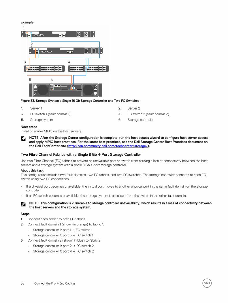
Example
Figure 33. Storage System a Single 16 Gb Storage Controller and Two FC Switches
1. Server 1 2. Server 2
3. FC switch 1 (fault domain 1) 4. FC switch 2 (fault domain 2)
5. Storage system 6. Storage controller
Next stepsInstall or enable MPIO on the host servers.
NOTE: After the Storage Center configuration is complete, run the host access wizard to configure host server access and apply MPIO best practices. For the latest best practices, see the Dell Storage Center Best Practices document on the Dell TechCenter site (http://en.community.dell.com/techcenter/storage/).
Two Fibre Channel Fabrics with a Single 8 Gb 4-Port Storage Controller
Use two Fibre Channel (FC) fabrics to prevent an unavailable port or switch from causing a loss of connectivity between the host servers and a storage system with a single 8 Gb 4-port storage controller.
About this taskThis configuration includes two fault domains, two FC fabrics, and two FC switches. The storage controller connects to each FC switch using two FC connections.
• If a physical port becomes unavailable, the virtual port moves to another physical port in the same fault domain on the storage controller.
• If an FC switch becomes unavailable, the storage system is accessed from the switch in the other fault domain.
NOTE: This configuration is vulnerable to storage controller unavailability, which results in a loss of connectivity between the host servers and the storage system.
Steps
1. Connect each server to both FC fabrics.
2. Connect fault domain 1 (shown in orange) to fabric 1.
• Storage controller 1: port 1 → FC switch 1
• Storage controller 1: port 3 → FC switch 1
3. Connect fault domain 2 (shown in blue) to fabric 2.
• Storage controller 1: port 2 → FC switch 2
• Storage controller 1: port 4 → FC switch 2
38 Connect the Front-End Cabling
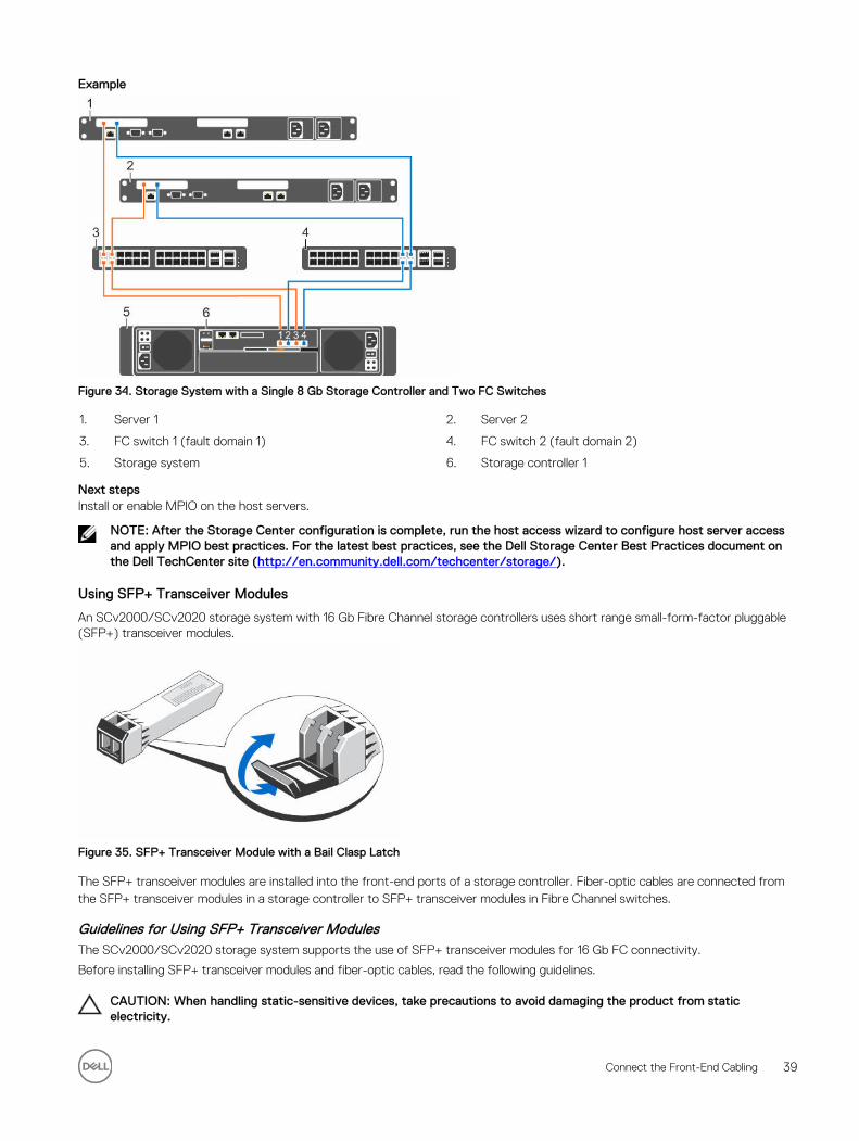
Example
Figure 34. Storage System with a Single 8 Gb Storage Controller and Two FC Switches
1. Server 1 2. Server 2
3. FC switch 1 (fault domain 1) 4. FC switch 2 (fault domain 2)
5. Storage system 6. Storage controller 1
Next stepsInstall or enable MPIO on the host servers.
NOTE: After the Storage Center configuration is complete, run the host access wizard to configure host server access and apply MPIO best practices. For the latest best practices, see the Dell Storage Center Best Practices document on the Dell TechCenter site (http://en.community.dell.com/techcenter/storage/).
Using SFP+ Transceiver Modules
An SCv2000/SCv2020 storage system with 16 Gb Fibre Channel storage controllers uses short range small-form-factor pluggable (SFP+) transceiver modules.
Figure 35. SFP+ Transceiver Module with a Bail Clasp Latch
The SFP+ transceiver modules are installed into the front-end ports of a storage controller. Fiber-optic cables are connected from the SFP+ transceiver modules in a storage controller to SFP+ transceiver modules in Fibre Channel switches.
Guidelines for Using SFP+ Transceiver ModulesThe SCv2000/SCv2020 storage system supports the use of SFP+ transceiver modules for 16 Gb FC connectivity.
Before installing SFP+ transceiver modules and fiber-optic cables, read the following guidelines.
CAUTION: When handling static-sensitive devices, take precautions to avoid damaging the product from static electricity.
Connect the Front-End Cabling 39
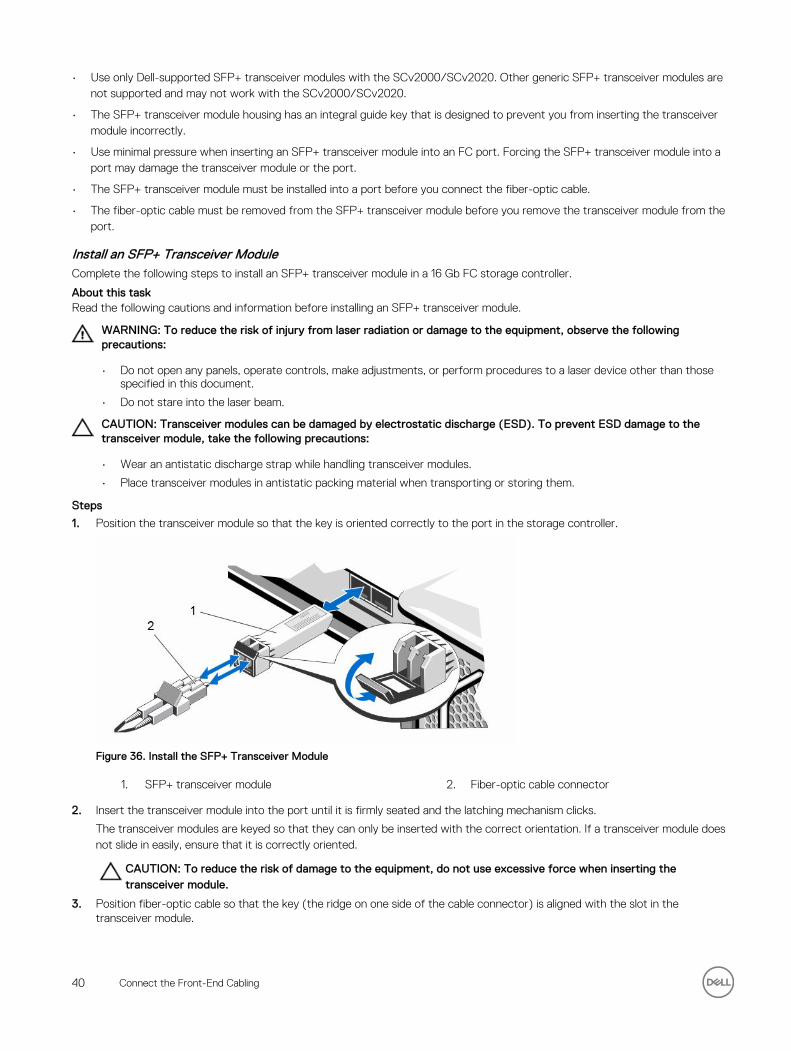
• Use only Dell-supported SFP+ transceiver modules with the SCv2000/SCv2020. Other generic SFP+ transceiver modules are not supported and may not work with the SCv2000/SCv2020.
• The SFP+ transceiver module housing has an integral guide key that is designed to prevent you from inserting the transceiver module incorrectly.
• Use minimal pressure when inserting an SFP+ transceiver module into an FC port. Forcing the SFP+ transceiver module into a port may damage the transceiver module or the port.
• The SFP+ transceiver module must be installed into a port before you connect the fiber-optic cable.
• The fiber-optic cable must be removed from the SFP+ transceiver module before you remove the transceiver module from the port.
Install an SFP+ Transceiver ModuleComplete the following steps to install an SFP+ transceiver module in a 16 Gb FC storage controller.
About this taskRead the following cautions and information before installing an SFP+ transceiver module.
WARNING: To reduce the risk of injury from laser radiation or damage to the equipment, observe the following precautions:
• Do not open any panels, operate controls, make adjustments, or perform procedures to a laser device other than those specified in this document.
• Do not stare into the laser beam.
CAUTION: Transceiver modules can be damaged by electrostatic discharge (ESD). To prevent ESD damage to the transceiver module, take the following precautions:
• Wear an antistatic discharge strap while handling transceiver modules.
• Place transceiver modules in antistatic packing material when transporting or storing them.
Steps
1. Position the transceiver module so that the key is oriented correctly to the port in the storage controller.
Figure 36. Install the SFP+ Transceiver Module
1. SFP+ transceiver module 2. Fiber-optic cable connector
2. Insert the transceiver module into the port until it is firmly seated and the latching mechanism clicks.
The transceiver modules are keyed so that they can only be inserted with the correct orientation. If a transceiver module does not slide in easily, ensure that it is correctly oriented.
CAUTION: To reduce the risk of damage to the equipment, do not use excessive force when inserting the transceiver module.
3. Position fiber-optic cable so that the key (the ridge on one side of the cable connector) is aligned with the slot in the transceiver module.
40 Connect the Front-End Cabling
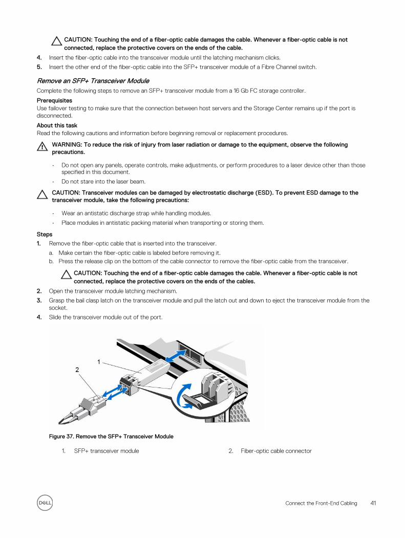
CAUTION: Touching the end of a fiber-optic cable damages the cable. Whenever a fiber-optic cable is not connected, replace the protective covers on the ends of the cable.
4. Insert the fiber-optic cable into the transceiver module until the latching mechanism clicks.
5. Insert the other end of the fiber-optic cable into the SFP+ transceiver module of a Fibre Channel switch.
Remove an SFP+ Transceiver ModuleComplete the following steps to remove an SFP+ transceiver module from a 16 Gb FC storage controller.
PrerequisitesUse failover testing to make sure that the connection between host servers and the Storage Center remains up if the port is disconnected.
About this taskRead the following cautions and information before beginning removal or replacement procedures.
WARNING: To reduce the risk of injury from laser radiation or damage to the equipment, observe the following precautions.
• Do not open any panels, operate controls, make adjustments, or perform procedures to a laser device other than those specified in this document.
• Do not stare into the laser beam.
CAUTION: Transceiver modules can be damaged by electrostatic discharge (ESD). To prevent ESD damage to the transceiver module, take the following precautions:
• Wear an antistatic discharge strap while handling modules.
• Place modules in antistatic packing material when transporting or storing them.
Steps
1. Remove the fiber-optic cable that is inserted into the transceiver.
a. Make certain the fiber-optic cable is labeled before removing it.b. Press the release clip on the bottom of the cable connector to remove the fiber-optic cable from the transceiver.
CAUTION: Touching the end of a fiber-optic cable damages the cable. Whenever a fiber-optic cable is not connected, replace the protective covers on the ends of the cables.
2. Open the transceiver module latching mechanism.
3. Grasp the bail clasp latch on the transceiver module and pull the latch out and down to eject the transceiver module from the socket.
4. Slide the transceiver module out of the port.
Figure 37. Remove the SFP+ Transceiver Module
1. SFP+ transceiver module 2. Fiber-optic cable connector
Connect the Front-End Cabling 41
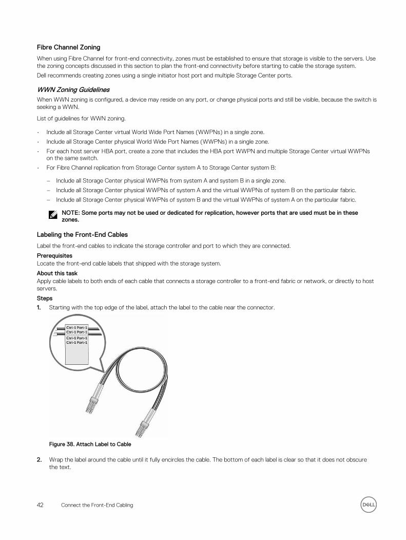
Fibre Channel Zoning
When using Fibre Channel for front-end connectivity, zones must be established to ensure that storage is visible to the servers. Use the zoning concepts discussed in this section to plan the front-end connectivity before starting to cable the storage system.
Dell recommends creating zones using a single initiator host port and multiple Storage Center ports.
WWN Zoning GuidelinesWhen WWN zoning is configured, a device may reside on any port, or change physical ports and still be visible, because the switch is seeking a WWN.
List of guidelines for WWN zoning.
• Include all Storage Center virtual World Wide Port Names (WWPNs) in a single zone.
• Include all Storage Center physical World Wide Port Names (WWPNs) in a single zone.
• For each host server HBA port, create a zone that includes the HBA port WWPN and multiple Storage Center virtual WWPNs on the same switch.
• For Fibre Channel replication from Storage Center system A to Storage Center system B:
– Include all Storage Center physical WWPNs from system A and system B in a single zone.
– Include all Storage Center physical WWPNs of system A and the virtual WWPNs of system B on the particular fabric.
– Include all Storage Center physical WWPNs of system B and the virtual WWPNs of system A on the particular fabric.
NOTE: Some ports may not be used or dedicated for replication, however ports that are used must be in these zones.
Labeling the Front-End Cables
Label the front-end cables to indicate the storage controller and port to which they are connected.
PrerequisitesLocate the front-end cable labels that shipped with the storage system.
About this taskApply cable labels to both ends of each cable that connects a storage controller to a front-end fabric or network, or directly to host servers.
Steps
1. Starting with the top edge of the label, attach the label to the cable near the connector.
Figure 38. Attach Label to Cable
2. Wrap the label around the cable until it fully encircles the cable. The bottom of each label is clear so that it does not obscure the text.
42 Connect the Front-End Cabling
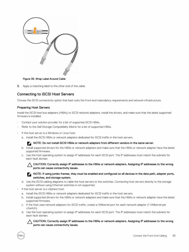
Figure 39. Wrap Label Around Cable
3. Apply a matching label to the other end of the cable.
Connecting to iSCSI Host Servers
Choose the iSCSI connectivity option that best suits the front‐end redundancy requirements and network infrastructure.
Preparing Host Servers
Install the iSCSI host bus adapters (HBAs) or iSCSI network adapters, install the drivers, and make sure that the latest supported firmware is installed.
• Contact your solution provider for a list of supported iSCSI HBAs.
• Refer to the Dell Storage Compatibility Matrix for a list of supported HBAs.
• If the host server is a Windows or Linux host:
a. Install the iSCSI HBAs or network adapters dedicated for iSCSI traffic in the host servers.
NOTE: Do not install iSCSI HBAs or network adapters from different vendors in the same server.
b. Install supported drivers for the HBAs or network adapters and make sure that the HBAs or network adapter have the latest supported firmware.
c. Use the host operating system to assign IP addresses for each iSCSI port. The IP addresses must match the subnets for each fault domain.
CAUTION: Correctly assign IP addresses to the HBAs or network adapters. Assigning IP addresses to the wrong ports can cause connectivity issues.
NOTE: If using jumbo frames, they must be enabled and configured on all devices in the data path, adapter ports, switches, and storage system.
d. Use the iSCSI cabling diagrams to cable the host servers to the switches. Connecting host servers directly to the storage system without using Ethernet switches is not supported.
• If the host server is a vSphere host:
a. Install the iSCSI HBAs or network adapters dedicated for iSCSI traffic in the host servers.b. Install supported drivers for the HBAs or network adapters and make sure that the HBAs or network adapter have the latest
supported firmware.c. If the host uses network adapters for iSCSI traffic, create a VMkernel port for each network adapter (1 VMkernel per
vSwitch).d. Use the host operating system to assign IP addresses for each iSCSI port. The IP addresses must match the subnets for
each fault domain.
CAUTION: Correctly assign IP addresses to the HBAs or network adapters. Assigning IP addresses to the wrong ports can cause connectivity issues.
Connect the Front-End Cabling 43
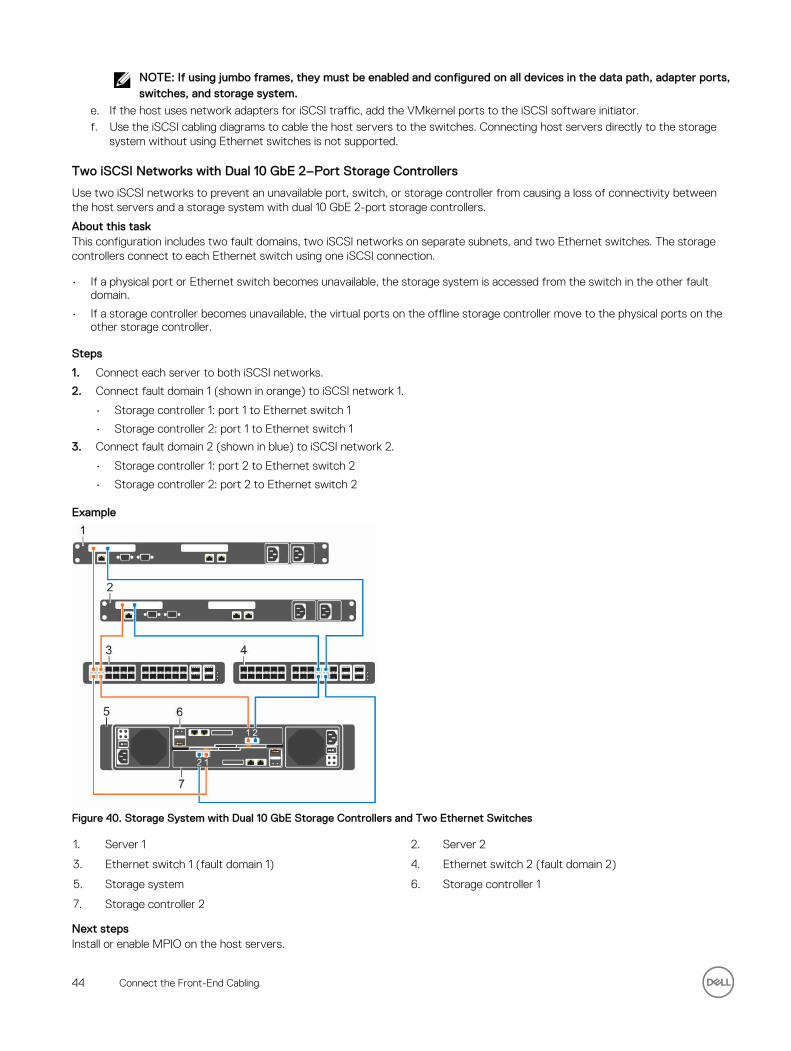
NOTE: If using jumbo frames, they must be enabled and configured on all devices in the data path, adapter ports, switches, and storage system.
e. If the host uses network adapters for iSCSI traffic, add the VMkernel ports to the iSCSI software initiator.f. Use the iSCSI cabling diagrams to cable the host servers to the switches. Connecting host servers directly to the storage
system without using Ethernet switches is not supported.
Two iSCSI Networks with Dual 10 GbE 2–Port Storage Controllers
Use two iSCSI networks to prevent an unavailable port, switch, or storage controller from causing a loss of connectivity between the host servers and a storage system with dual 10 GbE 2-port storage controllers.
About this taskThis configuration includes two fault domains, two iSCSI networks on separate subnets, and two Ethernet switches. The storage controllers connect to each Ethernet switch using one iSCSI connection.
• If a physical port or Ethernet switch becomes unavailable, the storage system is accessed from the switch in the other fault domain.
• If a storage controller becomes unavailable, the virtual ports on the offline storage controller move to the physical ports on the other storage controller.
Steps
1. Connect each server to both iSCSI networks.
2. Connect fault domain 1 (shown in orange) to iSCSI network 1.
• Storage controller 1: port 1 to Ethernet switch 1
• Storage controller 2: port 1 to Ethernet switch 1
3. Connect fault domain 2 (shown in blue) to iSCSI network 2.
• Storage controller 1: port 2 to Ethernet switch 2
• Storage controller 2: port 2 to Ethernet switch 2
Example
Figure 40. Storage System with Dual 10 GbE Storage Controllers and Two Ethernet Switches
1. Server 1 2. Server 2
3. Ethernet switch 1 (fault domain 1) 4. Ethernet switch 2 (fault domain 2)
5. Storage system 6. Storage controller 1
7. Storage controller 2
Next stepsInstall or enable MPIO on the host servers.
44 Connect the Front-End Cabling
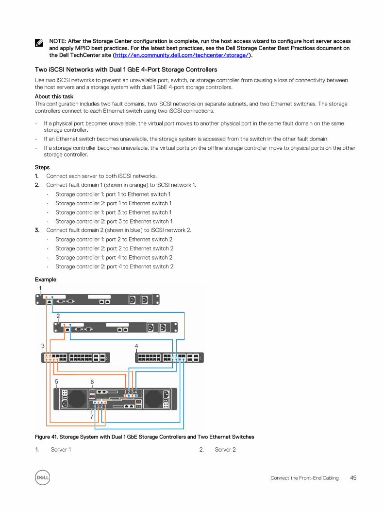
NOTE: After the Storage Center configuration is complete, run the host access wizard to configure host server access and apply MPIO best practices. For the latest best practices, see the Dell Storage Center Best Practices document on the Dell TechCenter site (http://en.community.dell.com/techcenter/storage/).
Two iSCSI Networks with Dual 1 GbE 4-Port Storage Controllers
Use two iSCSI networks to prevent an unavailable port, switch, or storage controller from causing a loss of connectivity between the host servers and a storage system with dual 1 GbE 4-port storage controllers.
About this taskThis configuration includes two fault domains, two iSCSI networks on separate subnets, and two Ethernet switches. The storage controllers connect to each Ethernet switch using two iSCSI connections.
• If a physical port becomes unavailable, the virtual port moves to another physical port in the same fault domain on the same storage controller.
• If an Ethernet switch becomes unavailable, the storage system is accessed from the switch in the other fault domain.
• If a storage controller becomes unavailable, the virtual ports on the offline storage controller move to physical ports on the other storage controller.
Steps
1. Connect each server to both iSCSI networks.
2. Connect fault domain 1 (shown in orange) to iSCSI network 1.
• Storage controller 1: port 1 to Ethernet switch 1
• Storage controller 2: port 1 to Ethernet switch 1
• Storage controller 1: port 3 to Ethernet switch 1
• Storage controller 2: port 3 to Ethernet switch 1
3. Connect fault domain 2 (shown in blue) to iSCSI network 2.
• Storage controller 1: port 2 to Ethernet switch 2
• Storage controller 2: port 2 to Ethernet switch 2
• Storage controller 1: port 4 to Ethernet switch 2
• Storage controller 2: port 4 to Ethernet switch 2
Example
Figure 41. Storage System with Dual 1 GbE Storage Controllers and Two Ethernet Switches
1. Server 1 2. Server 2
Connect the Front-End Cabling 45
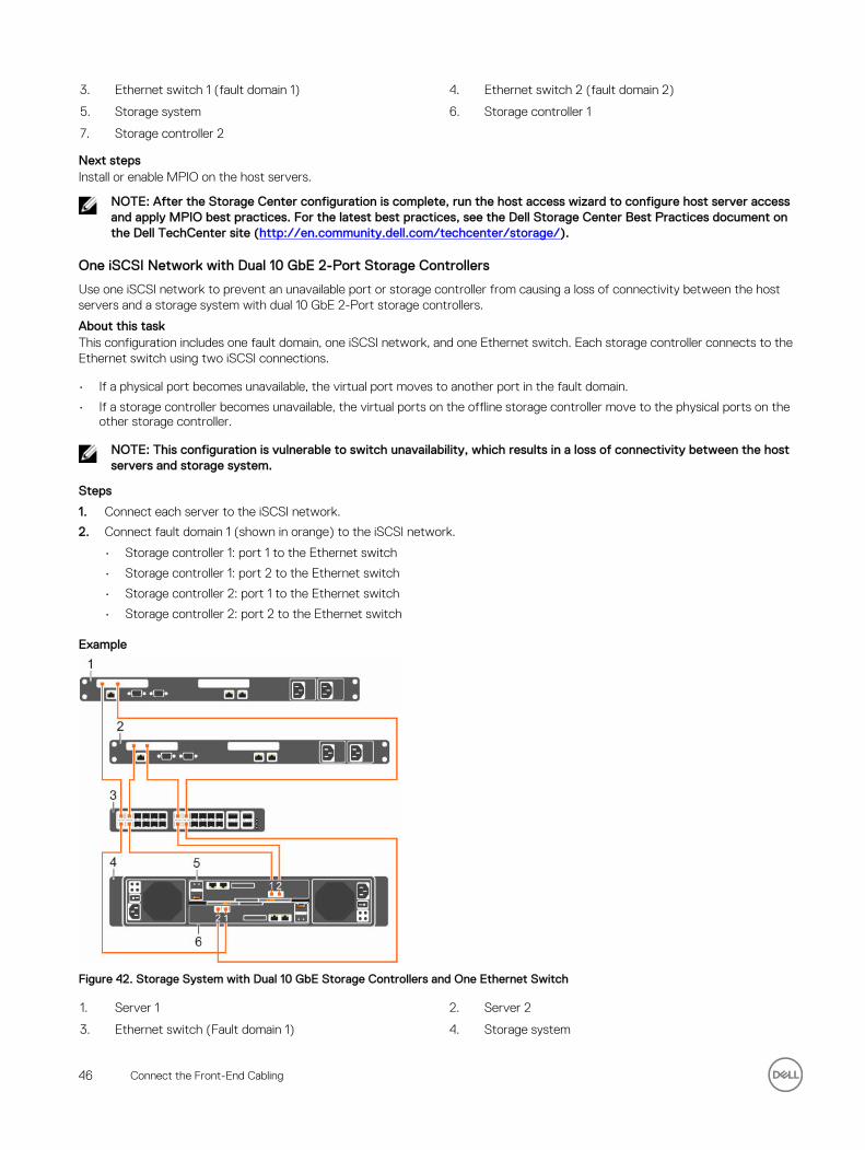
3. Ethernet switch 1 (fault domain 1) 4. Ethernet switch 2 (fault domain 2)
5. Storage system 6. Storage controller 1
7. Storage controller 2
Next stepsInstall or enable MPIO on the host servers.
NOTE: After the Storage Center configuration is complete, run the host access wizard to configure host server access and apply MPIO best practices. For the latest best practices, see the Dell Storage Center Best Practices document on the Dell TechCenter site (http://en.community.dell.com/techcenter/storage/).
One iSCSI Network with Dual 10 GbE 2-Port Storage Controllers
Use one iSCSI network to prevent an unavailable port or storage controller from causing a loss of connectivity between the host servers and a storage system with dual 10 GbE 2-Port storage controllers.
About this taskThis configuration includes one fault domain, one iSCSI network, and one Ethernet switch. Each storage controller connects to the Ethernet switch using two iSCSI connections.
• If a physical port becomes unavailable, the virtual port moves to another port in the fault domain.
• If a storage controller becomes unavailable, the virtual ports on the offline storage controller move to the physical ports on the other storage controller.
NOTE: This configuration is vulnerable to switch unavailability, which results in a loss of connectivity between the host servers and storage system.
Steps
1. Connect each server to the iSCSI network.
2. Connect fault domain 1 (shown in orange) to the iSCSI network.
• Storage controller 1: port 1 to the Ethernet switch
• Storage controller 1: port 2 to the Ethernet switch
• Storage controller 2: port 1 to the Ethernet switch
• Storage controller 2: port 2 to the Ethernet switch
Example
Figure 42. Storage System with Dual 10 GbE Storage Controllers and One Ethernet Switch
1. Server 1 2. Server 2
3. Ethernet switch (Fault domain 1) 4. Storage system
46 Connect the Front-End Cabling
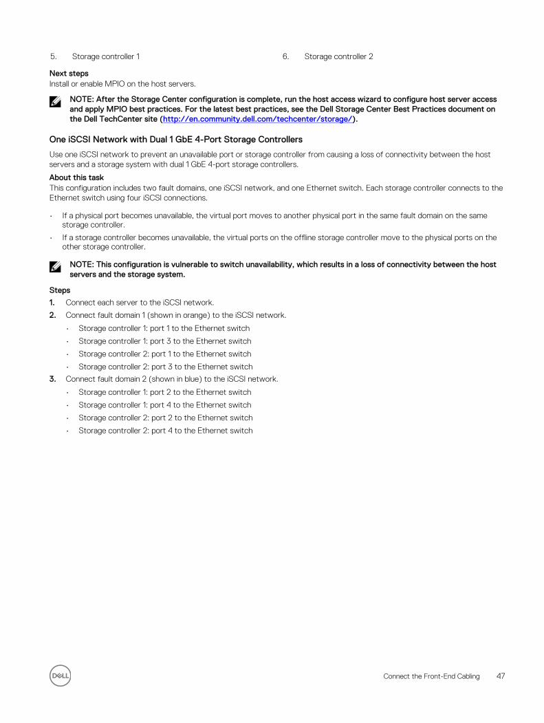
5. Storage controller 1 6. Storage controller 2
Next stepsInstall or enable MPIO on the host servers.
NOTE: After the Storage Center configuration is complete, run the host access wizard to configure host server access and apply MPIO best practices. For the latest best practices, see the Dell Storage Center Best Practices document on the Dell TechCenter site (http://en.community.dell.com/techcenter/storage/).
One iSCSI Network with Dual 1 GbE 4-Port Storage Controllers
Use one iSCSI network to prevent an unavailable port or storage controller from causing a loss of connectivity between the host servers and a storage system with dual 1 GbE 4-port storage controllers.
About this taskThis configuration includes two fault domains, one iSCSI network, and one Ethernet switch. Each storage controller connects to the Ethernet switch using four iSCSI connections.
• If a physical port becomes unavailable, the virtual port moves to another physical port in the same fault domain on the same storage controller.
• If a storage controller becomes unavailable, the virtual ports on the offline storage controller move to the physical ports on the other storage controller.
NOTE: This configuration is vulnerable to switch unavailability, which results in a loss of connectivity between the host servers and the storage system.
Steps
1. Connect each server to the iSCSI network.
2. Connect fault domain 1 (shown in orange) to the iSCSI network.
• Storage controller 1: port 1 to the Ethernet switch
• Storage controller 1: port 3 to the Ethernet switch
• Storage controller 2: port 1 to the Ethernet switch
• Storage controller 2: port 3 to the Ethernet switch
3. Connect fault domain 2 (shown in blue) to the iSCSI network.
• Storage controller 1: port 2 to the Ethernet switch
• Storage controller 1: port 4 to the Ethernet switch
• Storage controller 2: port 2 to the Ethernet switch
• Storage controller 2: port 4 to the Ethernet switch
Connect the Front-End Cabling 47
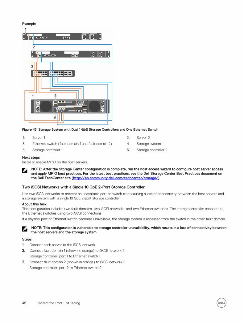
Example
Figure 43. Storage System with Dual 1 GbE Storage Controllers and One Ethernet Switch
1. Server 1 2. Server 2
3. Ethernet switch (fault domain 1 and fault domain 2) 4. Storage system
5. Storage controller 1 6. Storage controller 2
Next stepsInstall or enable MPIO on the host servers.
NOTE: After the Storage Center configuration is complete, run the host access wizard to configure host server access and apply MPIO best practices. For the latest best practices, see the Dell Storage Center Best Practices document on the Dell TechCenter site (http://en.community.dell.com/techcenter/storage/).
Two iSCSI Networks with a Single 10 GbE 2-Port Storage Controller
Use two iSCSI networks to prevent an unavailable port or switch from causing a loss of connectivity between the host servers and a storage system with a single 10 GbE 2-port storage controller.
About this taskThis configuration includes two fault domains, two iSCSI networks, and two Ethernet switches. The storage controller connects to the Ethernet switches using two iSCSI connections.
If a physical port or Ethernet switch becomes unavailable, the storage system is accessed from the switch in the other fault domain.
NOTE: This configuration is vulnerable to storage controller unavailability, which results in a loss of connectivity between the host servers and the storage system.
Steps
1. Connect each server to the iSCSI network.
2. Connect fault domain 1 (shown in orange) to iSCSI network 1.
Storage controller: port 1 to Ethernet switch 1.
3. Connect fault domain 2 (shown in orange) to iSCSI network 2.
Storage controller: port 2 to Ethernet switch 2.
48 Connect the Front-End Cabling
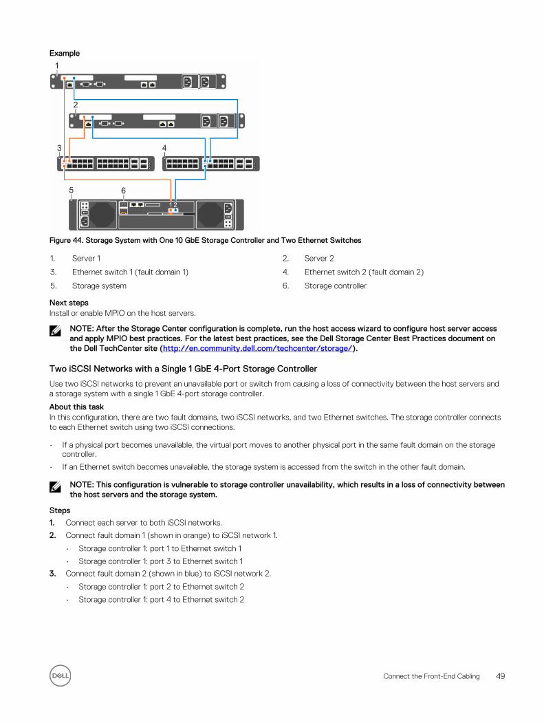
Example
Figure 44. Storage System with One 10 GbE Storage Controller and Two Ethernet Switches
1. Server 1 2. Server 2
3. Ethernet switch 1 (fault domain 1) 4. Ethernet switch 2 (fault domain 2)
5. Storage system 6. Storage controller
Next stepsInstall or enable MPIO on the host servers.
NOTE: After the Storage Center configuration is complete, run the host access wizard to configure host server access and apply MPIO best practices. For the latest best practices, see the Dell Storage Center Best Practices document on the Dell TechCenter site (http://en.community.dell.com/techcenter/storage/).
Two iSCSI Networks with a Single 1 GbE 4-Port Storage Controller
Use two iSCSI networks to prevent an unavailable port or switch from causing a loss of connectivity between the host servers and a storage system with a single 1 GbE 4-port storage controller.
About this taskIn this configuration, there are two fault domains, two iSCSI networks, and two Ethernet switches. The storage controller connects to each Ethernet switch using two iSCSI connections.
• If a physical port becomes unavailable, the virtual port moves to another physical port in the same fault domain on the storage controller.
• If an Ethernet switch becomes unavailable, the storage system is accessed from the switch in the other fault domain.
NOTE: This configuration is vulnerable to storage controller unavailability, which results in a loss of connectivity between the host servers and the storage system.
Steps
1. Connect each server to both iSCSI networks.
2. Connect fault domain 1 (shown in orange) to iSCSI network 1.
• Storage controller 1: port 1 to Ethernet switch 1
• Storage controller 1: port 3 to Ethernet switch 1
3. Connect fault domain 2 (shown in blue) to iSCSI network 2.
• Storage controller 1: port 2 to Ethernet switch 2
• Storage controller 1: port 4 to Ethernet switch 2
Connect the Front-End Cabling 49
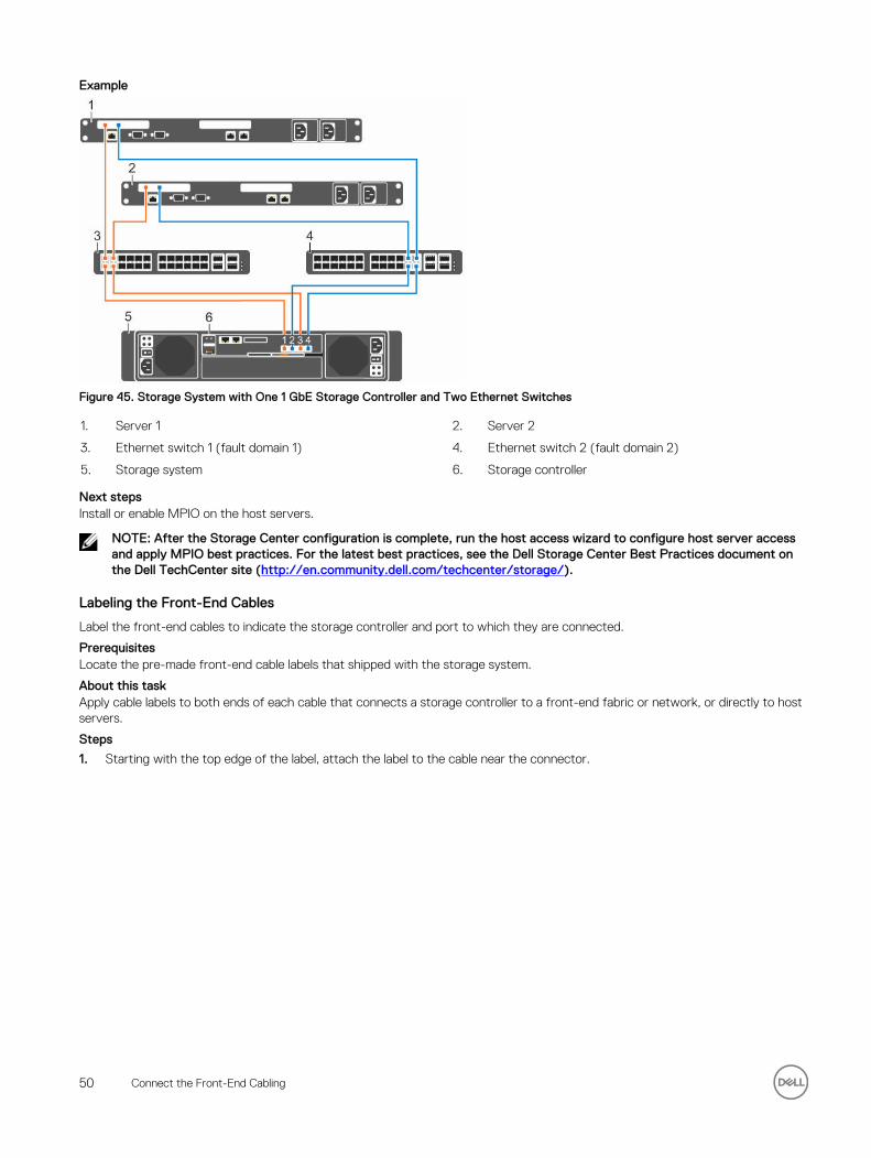
Example
Figure 45. Storage System with One 1 GbE Storage Controller and Two Ethernet Switches
1. Server 1 2. Server 2
3. Ethernet switch 1 (fault domain 1) 4. Ethernet switch 2 (fault domain 2)
5. Storage system 6. Storage controller
Next stepsInstall or enable MPIO on the host servers.
NOTE: After the Storage Center configuration is complete, run the host access wizard to configure host server access and apply MPIO best practices. For the latest best practices, see the Dell Storage Center Best Practices document on the Dell TechCenter site (http://en.community.dell.com/techcenter/storage/).
Labeling the Front-End Cables
Label the front-end cables to indicate the storage controller and port to which they are connected.
PrerequisitesLocate the pre-made front-end cable labels that shipped with the storage system.
About this taskApply cable labels to both ends of each cable that connects a storage controller to a front-end fabric or network, or directly to host servers.
Steps
1. Starting with the top edge of the label, attach the label to the cable near the connector.
50 Connect the Front-End Cabling
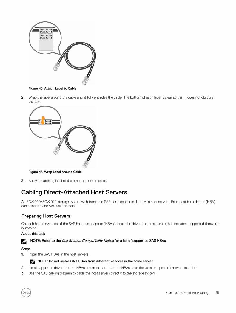
Figure 46. Attach Label to Cable
2. Wrap the label around the cable until it fully encircles the cable. The bottom of each label is clear so that it does not obscure the text
Figure 47. Wrap Label Around Cable
3. Apply a matching label to the other end of the cable.
Cabling Direct-Attached Host ServersAn SCv2000/SCv2020 storage system with front-end SAS ports connects directly to host servers. Each host bus adapter (HBA) can attach to one SAS fault domain.
Preparing Host Servers
On each host server, install the SAS host bus adapters (HBAs), install the drivers, and make sure that the latest supported firmware is installed.
About this task
NOTE: Refer to the Dell Storage Compatibility Matrix for a list of supported SAS HBAs.
Steps
1. Install the SAS HBAs in the host servers.
NOTE: Do not install SAS HBAs from different vendors in the same server.
2. Install supported drivers for the HBAs and make sure that the HBAs have the latest supported firmware installed.
3. Use the SAS cabling diagram to cable the host servers directly to the storage system.
Connect the Front-End Cabling 51
NOTE: If deploying vSphere hosts, configure only one host at a time.
SAS Virtual Port Mode
To provide redundancy in SAS virtual port mode, the front-end ports on each storage controller must be directly connected to the server.
In SAS virtual port mode, a volume is active on only one storage controller, but it is visible to both storage controllers. Asymmetric Logical Unit Access (ALUA) controls the path that a server uses to access a volume.
If a storage controller becomes unavailable, the volume becomes active on the other storage controller. The state of the paths on the available storage controller are set to Active/Optimized and the state of the paths on the other storage controller are set to Standby. When the storage controller becomes available again and the ports are rebalanced, the volume moves back to its preferred storage controller and the ALUA states are updated.
If a SAS path becomes unavailable, the Active/Optimized volumes on that path become active on the other storage controller. The state of the failed path for those volumes is set to Standby and the state of the active path for those volumes is set to Active/Optimized.
NOTE: Failover in SAS virtual port mode occurs within a single fault domain. Therefore, a server must have both connections in the same fault domain. For example, if a server is connected to SAS port 2 on one storage controller, it must be connected to SAS port two on the other storage controller. If a server is not cabled correctly when a storage controller or SAS path becomes unavailable, access to the volume is lost.
Four Servers Connected to Dual 12 Gb 4-Port SAS Storage Controllers
A storage system with four 12 Gb front-end SAS ports on each storage controller can connect to up to four host servers, if each host server has one HBA with dual SAS ports.
About this task
This configuration includes four fault domains spread across both storage controllers. The storage controllers are connected to each host server using two SAS connections.
If a storage controller becomes unavailable, all of the standby paths on the other storage controller become active.
Steps
1. Connect fault domain 1 (shown in orange) to host server 1.
a. Connect a SAS cable from storage controller 1: port 1 to the SAS HBA on host server 1.b. Connect a SAS cable from storage controller 2: port 1 to the SAS HBA on host server 1.
2. Connect fault domain 2 (shown in blue) to host server 2.
a. Connect a SAS cable from storage controller 1: port 2 to the SAS HBA on host server 2.b. Connect a SAS cable from storage controller 2: port 2 to the SAS HBA on host server 2.
3. Connect fault domain 3 (shown in gray) to host server 3.
a. Connect a SAS cable from storage controller 1: port 3 to the SAS HBA on host server 3.b. Connect a SAS cable from storage controller 2: port 3 to the SAS HBA on host server 3.
4. Connect fault domain 4 (shown in red) to host server 4.
a. Connect a SAS cable from storage controller 1: port 4 to the SAS HBA on host server 4.b. Connect a SAS cable from storage controller 2: port 4 to the SAS HBA on host server 4.
52 Connect the Front-End Cabling
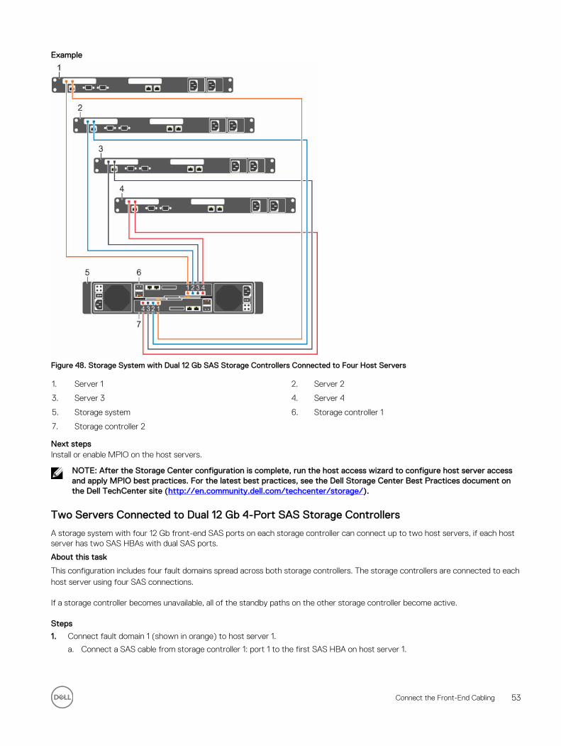
Example
Figure 48. Storage System with Dual 12 Gb SAS Storage Controllers Connected to Four Host Servers
1. Server 1 2. Server 2
3. Server 3 4. Server 4
5. Storage system 6. Storage controller 1
7. Storage controller 2
Next stepsInstall or enable MPIO on the host servers.
NOTE: After the Storage Center configuration is complete, run the host access wizard to configure host server access and apply MPIO best practices. For the latest best practices, see the Dell Storage Center Best Practices document on the Dell TechCenter site (http://en.community.dell.com/techcenter/storage/).
Two Servers Connected to Dual 12 Gb 4-Port SAS Storage Controllers
A storage system with four 12 Gb front-end SAS ports on each storage controller can connect up to two host servers, if each host server has two SAS HBAs with dual SAS ports.
About this task
This configuration includes four fault domains spread across both storage controllers. The storage controllers are connected to each host server using four SAS connections.
If a storage controller becomes unavailable, all of the standby paths on the other storage controller become active.
Steps
1. Connect fault domain 1 (shown in orange) to host server 1.
a. Connect a SAS cable from storage controller 1: port 1 to the first SAS HBA on host server 1.
Connect the Front-End Cabling 53
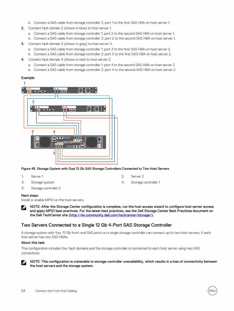
b. Connect a SAS cable from storage controller 2: port 1 to the first SAS HBA on host server 1.
2. Connect fault domain 2 (shown in blue) to host server 1.
a. Connect a SAS cable from storage controller 1: port 2 to the second SAS HBA on host server 1.b. Connect a SAS cable from storage controller 2: port 2 to the second SAS HBA on host server 1.
3. Connect fault domain 3 (shown in gray) to host server 2.
a. Connect a SAS cable from storage controller 1: port 3 to the first SAS HBA on host server 2.b. Connect a SAS cable from storage controller 2: port 3 to the first SAS HBA on host server 2.
4. Connect fault domain 4 (shown in red) to host server 2.
a. Connect a SAS cable from storage controller 1: port 4 to the second SAS HBA on host server 2b. Connect a SAS cable from storage controller 2: port 4 to the second SAS HBA on host server 2
Example
Figure 49. Storage System with Dual 12 Gb SAS Storage Controllers Connected to Two Host Servers
1. Server 1 2. Server 2
3. Storage system 4. Storage controller 1
5. Storage controller 2
Next stepsInstall or enable MPIO on the host servers.
NOTE: After the Storage Center configuration is complete, run the host access wizard to configure host server access and apply MPIO best practices. For the latest best practices, see the Dell Storage Center Best Practices document on the Dell TechCenter site (http://en.community.dell.com/techcenter/storage/).
Two Servers Connected to a Single 12 Gb 4-Port SAS Storage Controller
A storage system with four 12 Gb front-end SAS ports on a single storage controller can connect up to two host servers, if each host server has two SAS HBAs.
About this task
This configuration includes four fault domains and the storage controller is connected to each host server using two SAS connections.
NOTE: This configuration is vulnerable to storage controller unavailability, which results in a loss of connectivity between the host servers and the storage system.
54 Connect the Front-End Cabling

Steps
1. Connect fault domain 1 to host server 1 by connecting a SAS cable from storage controller 1: port 1 to host server 1.
2. Connect fault domain 2 to host server 1 by connecting a SAS cable from storage controller 1: port 2 to host server 1.
3. Connect fault domain 3 to host server 2 by connecting a SAS cable from storage controller 1: port 3 to host server 2.
4. Connect fault domain 4 to host server 2 by connecting a SAS cable from storage controller 1: port 4 to host server 2.
Example
Figure 50. Storage System with One 12 Gb SAS Storage Controller Connected to Two Host Servers
1. Server 1 2. Server 2
3. Storage system 4. Storage controller
Next stepsInstall or enable MPIO on the host servers.
NOTE: After the Storage Center configuration is complete, run the host access wizard to configure host server access and apply MPIO best practices. For the latest best practices, see the Dell Storage Center Best Practices document on the Dell TechCenter site (http://en.community.dell.com/techcenter/storage/).
Labeling the Front-End Cables
Label the front-end cables to indicate the storage controller and port to which they are connected.
PrerequisitesLocate the pre-made front-end cable labels that shipped with the storage system.
About this taskApply cable labels to both ends of each cable that connects a storage controller to a front-end fabric or network, or directly to host servers.
Steps
1. Starting with the top edge of the label, attach the label to the cable near the connector.
Connect the Front-End Cabling 55
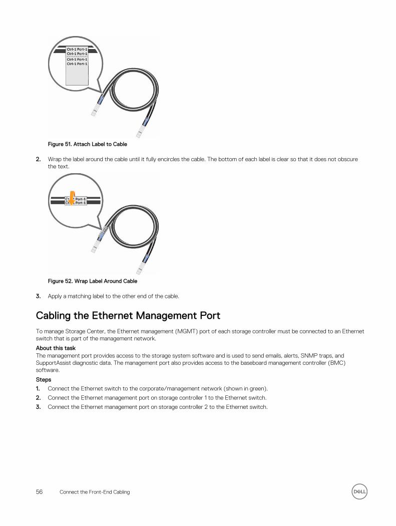
Figure 51. Attach Label to Cable
2. Wrap the label around the cable until it fully encircles the cable. The bottom of each label is clear so that it does not obscure the text.
Figure 52. Wrap Label Around Cable
3. Apply a matching label to the other end of the cable.
Cabling the Ethernet Management PortTo manage Storage Center, the Ethernet management (MGMT) port of each storage controller must be connected to an Ethernet switch that is part of the management network.
About this taskThe management port provides access to the storage system software and is used to send emails, alerts, SNMP traps, and SupportAssist diagnostic data. The management port also provides access to the baseboard management controller (BMC) software.
Steps
1. Connect the Ethernet switch to the corporate/management network (shown in green).
2. Connect the Ethernet management port on storage controller 1 to the Ethernet switch.
3. Connect the Ethernet management port on storage controller 2 to the Ethernet switch.
56 Connect the Front-End Cabling
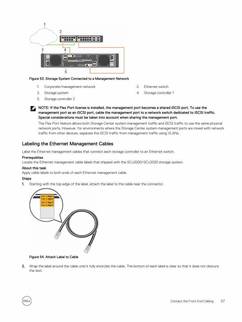
Figure 53. Storage System Connected to a Management Network
1. Corporate/management network 2. Ethernet switch
3. Storage system 4. Storage controller 1
5. Storage controller 2
NOTE: If the Flex Port license is installed, the management port becomes a shared iSCSI port. To use the management port as an iSCSI port, cable the management port to a network switch dedicated to iSCSI traffic. Special considerations must be taken into account when sharing the management port.
The Flex Port feature allows both Storage Center system management traffic and iSCSI traffic to use the same physical network ports. However, for environments where the Storage Center system management ports are mixed with network traffic from other devices, separate the iSCSI traffic from management traffic using VLANs.
Labeling the Ethernet Management Cables
Label the Ethernet management cables that connect each storage controller to an Ethernet switch.
PrerequisitesLocate the Ethernet management cable labels that shipped with the SCv2000/SCv2020 storage system.
About this taskApply cable labels to both ends of each Ethernet management cable.
Steps
1. Starting with the top edge of the label, attach the label to the cable near the connector.
Figure 54. Attach Label to Cable
2. Wrap the label around the cable until it fully encircles the cable. The bottom of each label is clear so that it does not obscure the text.
Connect the Front-End Cabling 57
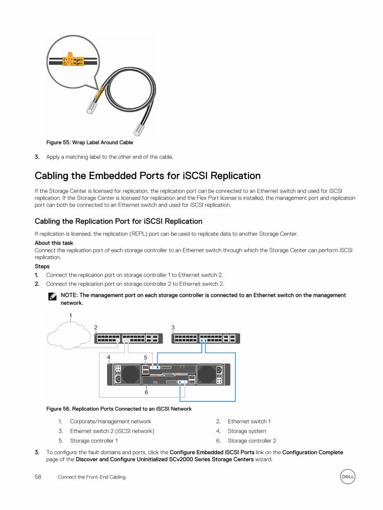
Figure 55. Wrap Label Around Cable
3. Apply a matching label to the other end of the cable.
Cabling the Embedded Ports for iSCSI ReplicationIf the Storage Center is licensed for replication, the replication port can be connected to an Ethernet switch and used for iSCSI replication. If the Storage Center is licensed for replication and the Flex Port license is installed, the management port and replication port can both be connected to an Ethernet switch and used for iSCSI replication.
Cabling the Replication Port for iSCSI Replication
If replication is licensed, the replication (REPL) port can be used to replicate data to another Storage Center.
About this taskConnect the replication port of each storage controller to an Ethernet switch through which the Storage Center can perform iSCSI replication.
Steps
1. Connect the replication port on storage controller 1 to Ethernet switch 2.
2. Connect the replication port on storage controller 2 to Ethernet switch 2.
NOTE: The management port on each storage controller is connected to an Ethernet switch on the management network.
Figure 56. Replication Ports Connected to an iSCSI Network
1. Corporate/management network 2. Ethernet switch 1
3. Ethernet switch 2 (iSCSI network) 4. Storage system
5. Storage controller 1 6. Storage controller 2
3. To configure the fault domains and ports, click the Configure Embedded iSCSI Ports link on the Configuration Complete page of the Discover and Configure Uninitialized SCv2000 Series Storage Centers wizard.
58 Connect the Front-End Cabling
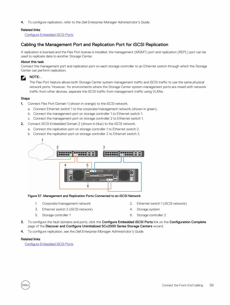
4. To configure replication, refer to the Dell Enterprise Manager Administrator’s Guide.
Related links
Configure Embedded iSCSI Ports
Cabling the Management Port and Replication Port for iSCSI Replication
If replication is licensed and the Flex Port license is installed, the management (MGMT) port and replication (REPL) port can be used to replicate data to another Storage Center.
About this taskConnect the management port and replication port on each storage controller to an Ethernet switch through which the Storage Center can perform replication.
NOTE: .
The Flex Port feature allows both Storage Center system management traffic and iSCSI traffic to use the same physical network ports. However, for environments where the Storage Center system management ports are mixed with network traffic from other devices, separate the iSCSI traffic from management traffic using VLANs.
Steps
1. Connect Flex Port Domain 1 (shown in orange) to the iSCSI network.
a. Connect Ethernet switch 1 to the corporate/management network (shown in green).b. Connect the management port on storage controller 1 to Ethernet switch 1.c. Connect the management port on storage controller 2 to Ethernet switch 1.
2. Connect iSCSI Embedded Domain 2 (shown in blue) to the iSCSI network.
a. Connect the replication port on storage controller 1 to Ethernet switch 2.b. Connect the replication port on storage controller 2 to Ethernet switch 2.
Figure 57. Management and Replication Ports Connected to an iSCSI Network
1. Corporate/management network 2. Ethernet switch 1 (iSCSI network)
3. Ethernet switch 2 (iSCSI network) 4. Storage system
5. Storage controller 1 6. Storage controller 2
3. To configure the fault domains and ports, click the Configure Embedded iSCSI Ports link on the Configuration Complete page of the Discover and Configure Uninitialized SCv2000 Series Storage Centers wizard.
4. To configure replication, see the Dell Enterprise Manager Administrator’s Guide.
Related links
Configure Embedded iSCSI Ports
Connect the Front-End Cabling 59
Cabling the Embedded Ports for iSCSI Host ConnectivityIf the Flex Port license is installed on the Storage Center, the management port and replication port can be connected to an Ethernet switch and used for iSCSI host connectivity.
Dell recommends using two switches dedicated for iSCSI traffic. Refer to the iSCSI Settings appendix for a list of recommend and required settings.
Two iSCSI Networks using the Embedded Ethernet Ports on a Storage System with Dual Fibre Channel Storage Controllers
Use two iSCSI networks to prevent an unavailable port, switch, or storage controller from causing a loss of connectivity between the host servers and a storage system with dual Fibre Channel (FC) storage controllers.
About this taskThis configuration includes two fault domains, two iSCSI networks, and two Ethernet switches.
• If a physical port or Ethernet switch becomes unavailable, the storage system is accessed from the switch in the other fault domain.
• If a storage controller becomes unavailable, the virtual ports on the offline storage controller move to the physical ports on the other storage controller.
NOTE: The Flex Port feature allows both Storage Center system management traffic and iSCSI traffic to use the same physical network ports. However, for environments where the Storage Center system management ports are mixed with network traffic from other devices (such as voice, backups, or other computing devices), separate iSCSI traffic from management traffic using VLANs.
Steps
1. Connect each server and Ethernet switch 1 to the corporate/management network (shown in green).
2. Connect the servers that support iSCSI connections to both iSCSI networks.
3. Connect embedded fault domain 1 (shown in orange) to iSCSI network 1.
a. Connect the management port on storage controller 1 to Ethernet switch 1.b. Connect the management port on storage controller 2 to Ethernet switch 1.
4. Connect embedded fault domain 2 (shown in blue) to iSCSI network 2.
a. Connect the replication port on storage controller 1 to Ethernet switch 2.b. Connect the replication port on storage controller 2 to Ethernet switch 2.
60 Connect the Front-End Cabling
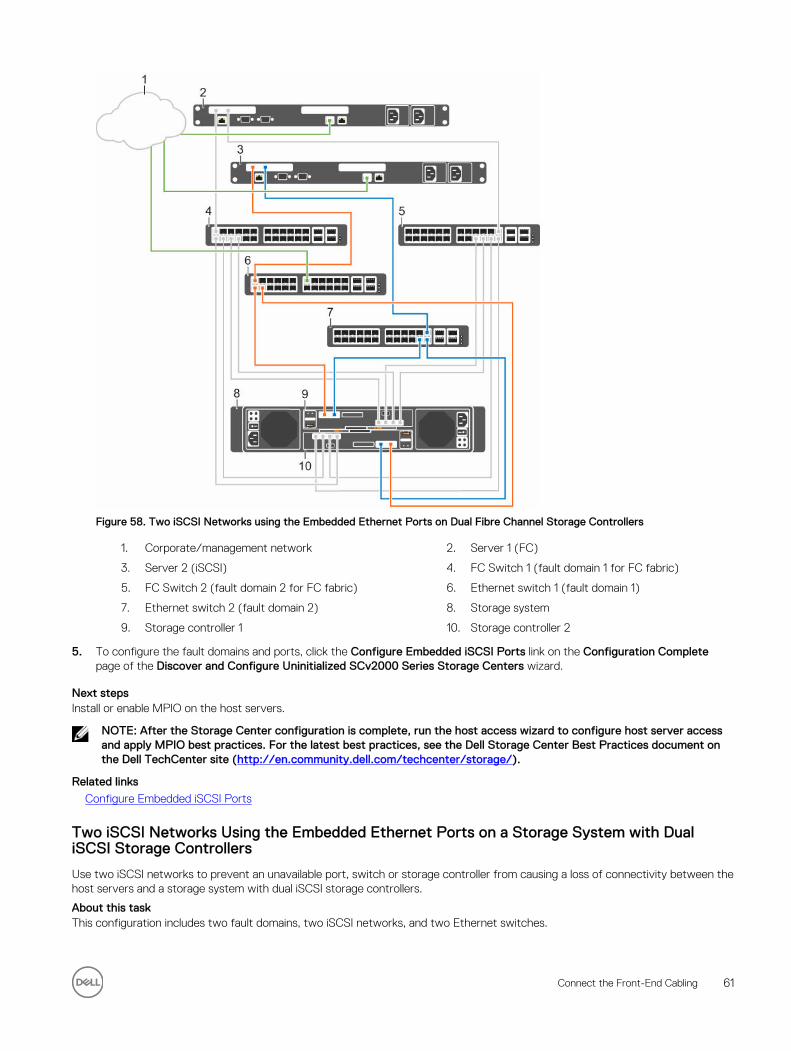
Figure 58. Two iSCSI Networks using the Embedded Ethernet Ports on Dual Fibre Channel Storage Controllers
1. Corporate/management network 2. Server 1 (FC)
3. Server 2 (iSCSI) 4. FC Switch 1 (fault domain 1 for FC fabric)
5. FC Switch 2 (fault domain 2 for FC fabric) 6. Ethernet switch 1 (fault domain 1)
7. Ethernet switch 2 (fault domain 2) 8. Storage system
9. Storage controller 1 10. Storage controller 2
5. To configure the fault domains and ports, click the Configure Embedded iSCSI Ports link on the Configuration Complete page of the Discover and Configure Uninitialized SCv2000 Series Storage Centers wizard.
Next stepsInstall or enable MPIO on the host servers.
NOTE: After the Storage Center configuration is complete, run the host access wizard to configure host server access and apply MPIO best practices. For the latest best practices, see the Dell Storage Center Best Practices document on the Dell TechCenter site (http://en.community.dell.com/techcenter/storage/).
Related links
Configure Embedded iSCSI Ports
Two iSCSI Networks Using the Embedded Ethernet Ports on a Storage System with Dual iSCSI Storage Controllers
Use two iSCSI networks to prevent an unavailable port, switch or storage controller from causing a loss of connectivity between the host servers and a storage system with dual iSCSI storage controllers.
About this taskThis configuration includes two fault domains, two iSCSI networks, and two Ethernet switches.
Connect the Front-End Cabling 61
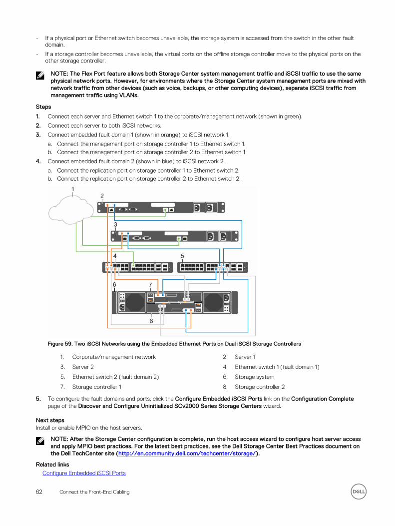
• If a physical port or Ethernet switch becomes unavailable, the storage system is accessed from the switch in the other fault domain.
• If a storage controller becomes unavailable, the virtual ports on the offline storage controller move to the physical ports on the other storage controller.
NOTE: The Flex Port feature allows both Storage Center system management traffic and iSCSI traffic to use the same physical network ports. However, for environments where the Storage Center system management ports are mixed with network traffic from other devices (such as voice, backups, or other computing devices), separate iSCSI traffic from management traffic using VLANs.
Steps
1. Connect each server and Ethernet switch 1 to the corporate/management network (shown in green).
2. Connect each server to both iSCSI networks.
3. Connect embedded fault domain 1 (shown in orange) to iSCSI network 1.
a. Connect the management port on storage controller 1 to Ethernet switch 1.b. Connect the management port on storage controller 2 to Ethernet switch 1
4. Connect embedded fault domain 2 (shown in blue) to iSCSI network 2.
a. Connect the replication port on storage controller 1 to Ethernet switch 2.b. Connect the replication port on storage controller 2 to Ethernet switch 2.
Figure 59. Two iSCSI Networks using the Embedded Ethernet Ports on Dual iSCSI Storage Controllers
1. Corporate/management network 2. Server 1
3. Server 2 4. Ethernet switch 1 (fault domain 1)
5. Ethernet switch 2 (fault domain 2) 6. Storage system
7. Storage controller 1 8. Storage controller 2
5. To configure the fault domains and ports, click the Configure Embedded iSCSI Ports link on the Configuration Complete page of the Discover and Configure Uninitialized SCv2000 Series Storage Centers wizard.
Next stepsInstall or enable MPIO on the host servers.
NOTE: After the Storage Center configuration is complete, run the host access wizard to configure host server access and apply MPIO best practices. For the latest best practices, see the Dell Storage Center Best Practices document on the Dell TechCenter site (http://en.community.dell.com/techcenter/storage/).
Related links
Configure Embedded iSCSI Ports
62 Connect the Front-End Cabling
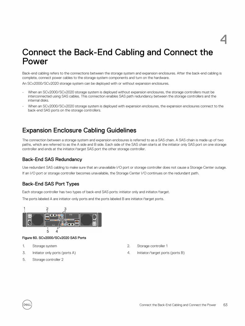
4Connect the Back-End Cabling and Connect the PowerBack-end cabling refers to the connections between the storage system and expansion enclosures. After the back-end cabling is complete, connect power cables to the storage system components and turn on the hardware.
An SCv2000/SCv2020 storage system can be deployed with or without expansion enclosures.
• When an SCv2000/SCv2020 storage system is deployed without expansion enclosures, the storage controllers must be interconnected using SAS cables. This connection enables SAS path redundancy between the storage controllers and the internal disks.
• When an SCv2000/SCv2020 storage system is deployed with expansion enclosures, the expansion enclosures connect to the back-end SAS ports on the storage controllers.
Expansion Enclosure Cabling GuidelinesThe connection between a storage system and expansion enclosures is referred to as a SAS chain. A SAS chain is made up of two paths, which are referred to as the A side and B side. Each side of the SAS chain starts at the initiator only SAS port on one storage controller and ends at the initiator/target SAS port the other storage controller.
Back-End SAS Redundancy
Use redundant SAS cabling to make sure that an unavailable I/O port or storage controller does not cause a Storage Center outage.
If an I/O port or storage controller becomes unavailable, the Storage Center I/O continues on the redundant path.
Back-End SAS Port Types
Each storage controller has two types of back-end SAS ports: initiator only and initiator/target.
The ports labeled A are initiator-only ports and the ports labeled B are initiator/target ports.
Figure 60. SCv2000/SCv2020 SAS Ports
1. Storage system 2. Storage controller 1
3. Initiator only ports (ports A) 4. Initiator/target ports (ports B)
5. Storage controller 2
Connect the Back-End Cabling and Connect the Power 63
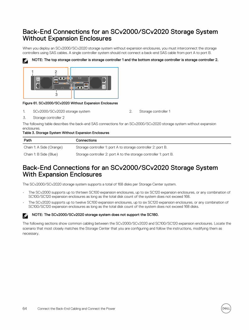
Back-End Connections for an SCv2000/SCv2020 Storage System Without Expansion EnclosuresWhen you deploy an SCv2000/SCv2020 storage system without expansion enclosures, you must interconnect the storage controllers using SAS cables. A single controller system should not connect a back-end SAS cable from port A to port B.
NOTE: The top storage controller is storage controller 1 and the bottom storage controller is storage controller 2.
Figure 61. SCv2000/SCv2020 Without Expansion Enclosures
1. SCv2000/SCv2020 storage system 2. Storage controller 1
3. Storage controller 2
The following table describes the back-end SAS connections for an SCv2000/SCv2020 storage system without expansion enclosures.Table 3. Storage System Without Expansion Enclosures
Path Connections
Chain 1: A Side (Orange) Storage controller 1: port A to storage controller 2: port B.
Chain 1: B Side (Blue) Storage controller 2: port A to the storage controller 1: port B.
Back-End Connections for an SCv2000/SCv2020 Storage System With Expansion EnclosuresThe SCv2000/SCv2020 storage system supports a total of 168 disks per Storage Center system.
• The SCv2000 supports up to thirteen SC100 expansion enclosures, up to six SC120 expansion enclosures, or any combination of SC100/SC120 expansion enclosures as long as the total disk count of the system does not exceed 168.
• The SCv2020 supports up to twelve SC100 expansion enclosures, up to six SC120 expansion enclosures, or any combination of SC100/SC120 expansion enclosures as long as the total disk count of the system does not exceed 168 disks.
NOTE: The SCv2000/SCv2020 storage system does not support the SC180.
The following sections show common cabling between the SCv2000/SCv2020 and SC100/SC120 expansion enclosures. Locate the scenario that most closely matches the Storage Center that you are configuring and follow the instructions, modifying them as necessary.
64 Connect the Back-End Cabling and Connect the Power
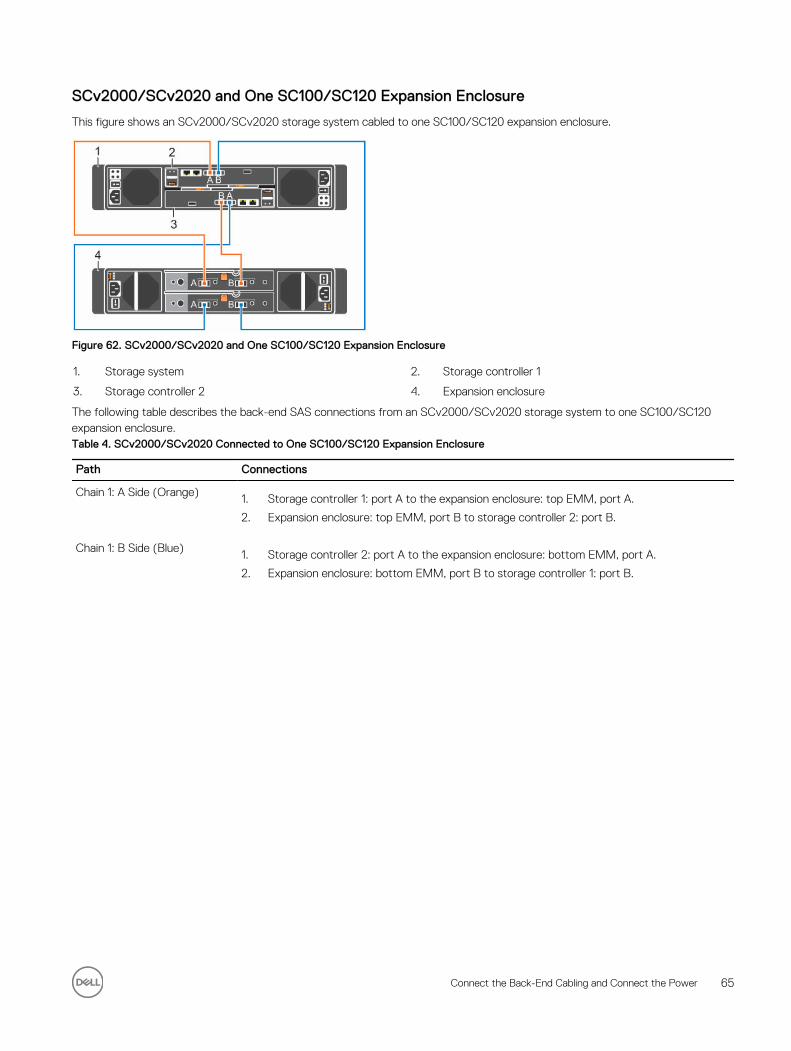
SCv2000/SCv2020 and One SC100/SC120 Expansion Enclosure
This figure shows an SCv2000/SCv2020 storage system cabled to one SC100/SC120 expansion enclosure.
Figure 62. SCv2000/SCv2020 and One SC100/SC120 Expansion Enclosure
1. Storage system 2. Storage controller 1
3. Storage controller 2 4. Expansion enclosure
The following table describes the back-end SAS connections from an SCv2000/SCv2020 storage system to one SC100/SC120 expansion enclosure.Table 4. SCv2000/SCv2020 Connected to One SC100/SC120 Expansion Enclosure
Path Connections
Chain 1: A Side (Orange) 1. Storage controller 1: port A to the expansion enclosure: top EMM, port A.
2. Expansion enclosure: top EMM, port B to storage controller 2: port B.
Chain 1: B Side (Blue) 1. Storage controller 2: port A to the expansion enclosure: bottom EMM, port A.
2. Expansion enclosure: bottom EMM, port B to storage controller 1: port B.
Connect the Back-End Cabling and Connect the Power 65
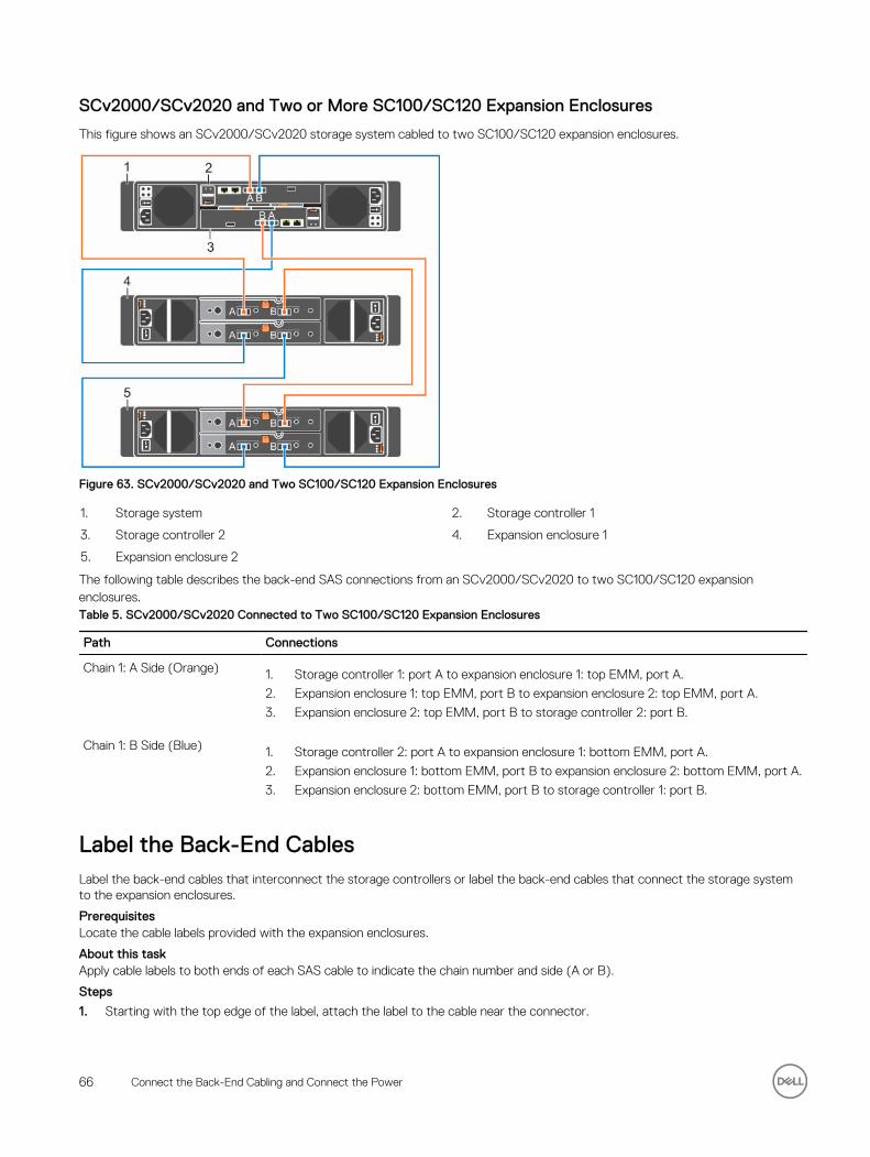
SCv2000/SCv2020 and Two or More SC100/SC120 Expansion Enclosures
This figure shows an SCv2000/SCv2020 storage system cabled to two SC100/SC120 expansion enclosures.
Figure 63. SCv2000/SCv2020 and Two SC100/SC120 Expansion Enclosures
1. Storage system 2. Storage controller 1
3. Storage controller 2 4. Expansion enclosure 1
5. Expansion enclosure 2
The following table describes the back-end SAS connections from an SCv2000/SCv2020 to two SC100/SC120 expansion enclosures.Table 5. SCv2000/SCv2020 Connected to Two SC100/SC120 Expansion Enclosures
Path Connections
Chain 1: A Side (Orange) 1. Storage controller 1: port A to expansion enclosure 1: top EMM, port A.
2. Expansion enclosure 1: top EMM, port B to expansion enclosure 2: top EMM, port A.
3. Expansion enclosure 2: top EMM, port B to storage controller 2: port B.
Chain 1: B Side (Blue) 1. Storage controller 2: port A to expansion enclosure 1: bottom EMM, port A.
2. Expansion enclosure 1: bottom EMM, port B to expansion enclosure 2: bottom EMM, port A.
3. Expansion enclosure 2: bottom EMM, port B to storage controller 1: port B.
Label the Back-End CablesLabel the back-end cables that interconnect the storage controllers or label the back-end cables that connect the storage system to the expansion enclosures.
PrerequisitesLocate the cable labels provided with the expansion enclosures.
About this taskApply cable labels to both ends of each SAS cable to indicate the chain number and side (A or B).
Steps
1. Starting with the top edge of the label, attach the label to the cable near the connector.
66 Connect the Back-End Cabling and Connect the Power
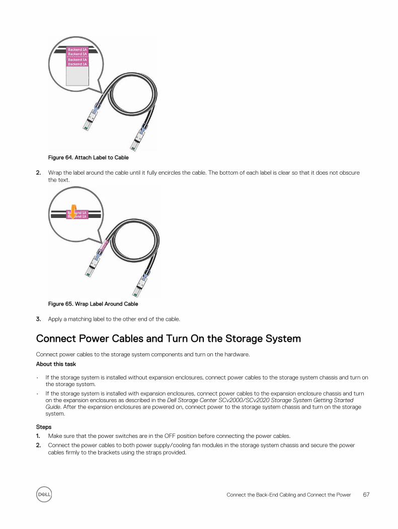
Figure 64. Attach Label to Cable
2. Wrap the label around the cable until it fully encircles the cable. The bottom of each label is clear so that it does not obscure the text.
Figure 65. Wrap Label Around Cable
3. Apply a matching label to the other end of the cable.
Connect Power Cables and Turn On the Storage SystemConnect power cables to the storage system components and turn on the hardware.
About this task
• If the storage system is installed without expansion enclosures, connect power cables to the storage system chassis and turn on the storage system.
• If the storage system is installed with expansion enclosures, connect power cables to the expansion enclosure chassis and turn on the expansion enclosures as described in the Dell Storage Center SCv2000/SCv2020 Storage System Getting Started Guide. After the expansion enclosures are powered on, connect power to the storage system chassis and turn on the storage system.
Steps
1. Make sure that the power switches are in the OFF position before connecting the power cables.
2. Connect the power cables to both power supply/cooling fan modules in the storage system chassis and secure the power cables firmly to the brackets using the straps provided.
Connect the Back-End Cabling and Connect the Power 67
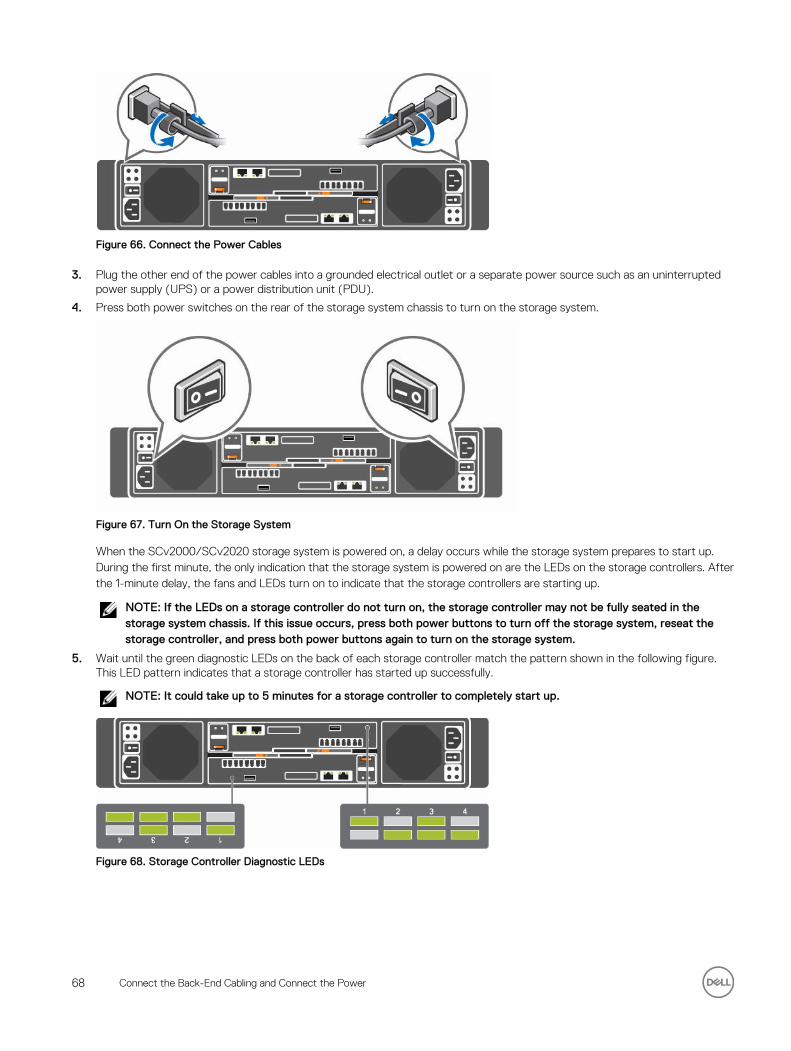
Figure 66. Connect the Power Cables
3. Plug the other end of the power cables into a grounded electrical outlet or a separate power source such as an uninterrupted power supply (UPS) or a power distribution unit (PDU).
4. Press both power switches on the rear of the storage system chassis to turn on the storage system.
Figure 67. Turn On the Storage System
When the SCv2000/SCv2020 storage system is powered on, a delay occurs while the storage system prepares to start up. During the first minute, the only indication that the storage system is powered on are the LEDs on the storage controllers. After the 1-minute delay, the fans and LEDs turn on to indicate that the storage controllers are starting up.
NOTE: If the LEDs on a storage controller do not turn on, the storage controller may not be fully seated in the storage system chassis. If this issue occurs, press both power buttons to turn off the storage system, reseat the storage controller, and press both power buttons again to turn on the storage system.
5. Wait until the green diagnostic LEDs on the back of each storage controller match the pattern shown in the following figure. This LED pattern indicates that a storage controller has started up successfully.
NOTE: It could take up to 5 minutes for a storage controller to completely start up.
Figure 68. Storage Controller Diagnostic LEDs
68 Connect the Back-End Cabling and Connect the Power

5Discover and Configure the Storage CenterThe Discover and Configure Uninitialized SCv2000 Series Storage Centers wizard allows you to set up a Storage Center to make it ready for volume creation.
Use the Dell Storage Manager Client to discover and configure the Storage Center. After configuring a Storage Center, you can set up a localhost, VMware vSphere host, or VMware vCenter host using the host setup wizards.
The storage system hardware must be installed and cabled before the Storage Center can be configured.
Locating Your Service TagYour storage system is identified by a unique service tag and Express Service Code.
You can find the service tag and Express Service Code on the service luggage tag located next to the front panel display. Alternatively, the information may be on a sticker on the back of the storage system chassis. Dell uses this information to route support calls to the appropriate personnel.
Figure 69. Service Tag Locations
1. Service luggage tag 2. Service tag label
Worksheet to Record System InformationUse the following worksheet to record the information that is needed to install the SCv2000/SCv2020 storage system.
Storage Center Information
Gather and record the following information about the Storage Center network and the administrator user.
Table 6. Storage Center Network
Service Tag ________________
Management IPv4 address (Storage Center management address) ___ . ___ . ___ . ___
Top Controller IPv4 address (Controller 1 MGMT port) ___ . ___ . ___ . ___
Bottom Controller IPv4 address (Controller 2 MGMT port) ___ . ___ . ___ . ___
Discover and Configure the Storage Center 69
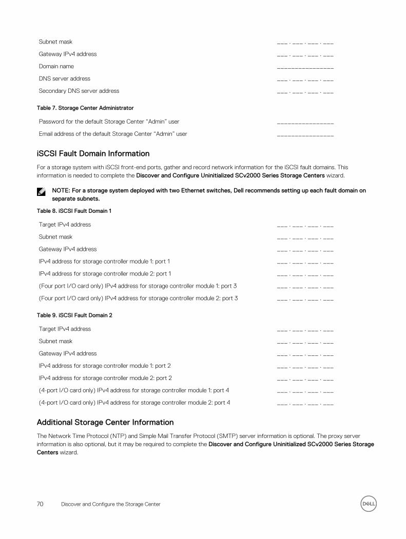
Subnet mask ___ . ___ . ___ . ___
Gateway IPv4 address ___ . ___ . ___ . ___
Domain name ________________
DNS server address ___ . ___ . ___ . ___
Secondary DNS server address ___ . ___ . ___ . ___
Table 7. Storage Center Administrator
Password for the default Storage Center “Admin” user ________________
Email address of the default Storage Center “Admin” user ________________
iSCSI Fault Domain Information
For a storage system with iSCSI front-end ports, gather and record network information for the iSCSI fault domains. This information is needed to complete the Discover and Configure Uninitialized SCv2000 Series Storage Centers wizard.
NOTE: For a storage system deployed with two Ethernet switches, Dell recommends setting up each fault domain on separate subnets.
Table 8. iSCSI Fault Domain 1
Target IPv4 address ___ . ___ . ___ . ___
Subnet mask ___ . ___ . ___ . ___
Gateway IPv4 address ___ . ___ . ___ . ___
IPv4 address for storage controller module 1: port 1 ___ . ___ . ___ . ___
IPv4 address for storage controller module 2: port 1 ___ . ___ . ___ . ___
(Four port I/O card only) IPv4 address for storage controller module 1: port 3 ___ . ___ . ___ . ___
(Four port I/O card only) IPv4 address for storage controller module 2: port 3 ___ . ___ . ___ . ___
Table 9. iSCSI Fault Domain 2
Target IPv4 address ___ . ___ . ___ . ___
Subnet mask ___ . ___ . ___ . ___
Gateway IPv4 address ___ . ___ . ___ . ___
IPv4 address for storage controller module 1: port 2 ___ . ___ . ___ . ___
IPv4 address for storage controller module 2: port 2 ___ . ___ . ___ . ___
(4-port I/O card only) IPv4 address for storage controller module 1: port 4 ___ . ___ . ___ . ___
(4-port I/O card only) IPv4 address for storage controller module 2: port 4 ___ . ___ . ___ . ___
Additional Storage Center Information
The Network Time Protocol (NTP) and Simple Mail Transfer Protocol (SMTP) server information is optional. The proxy server information is also optional, but it may be required to complete the Discover and Configure Uninitialized SCv2000 Series Storage Centers wizard.
70 Discover and Configure the Storage Center
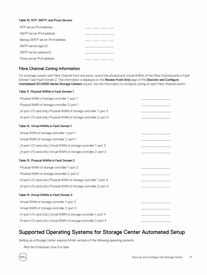
Table 10. NTP, SMTP, and Proxy Servers
NTP server IPv4 address ___ . ___ . ___ . ___
SMTP server IPv4 address ___ . ___ . ___ . ___
Backup SMTP server IPv4 address ___ . ___ . ___ . ___
SMTP server login ID ________________
SMTP server password ________________
Proxy server IPv4 address ___ . ___ . ___ . ___
Fibre Channel Zoning Information
For a storage system with Fibre Channel front-end ports, record the physical and virtual WWNs of the Fibre Channel ports in Fault Domain 1 and Fault Domain 2. This information is displayed on the Review Front-End page of the Discover and Configure Uninitialized SCv2000 Series Storage Centers wizard. Use this information to configure zoning on each Fibre Channel switch.
Table 11. Physical WWNs in Fault Domain 1
Physical WWN of storage controller 1: port 1 ________________
Physical WWN of storage controller 2: port 1 ________________
(4-port I/O card only) Physical WWN of storage controller 1: port 3 ________________
(4-port I/O card only) Physical WWN of storage controller 2: port 3 ________________
Table 12. Virtual WWNs in Fault Domain 1
Virtual WWN of storage controller 1: port 1 ________________
Virtual WWN of storage controller 2: port 1 ________________
(4-port I/O card only) Virtual WWN of storage controller 1: port 3 ________________
(4-port I/O card only) Virtual WWN of storage controller 2: port 3 ________________
Table 13. Physical WWNs in Fault Domain 2
Physical WWN of storage controller 1: port 2 ________________
Physical WWN of storage controller 2: port 2 ________________
(4-port I/O card only) Physical WWN of storage controller 1: port 4 ________________
(4-port I/O card only) Physical WWN of storage controller 2: port 4 ________________
Table 14. Virtual WWNs in Fault Domain 2
Virtual WWN of storage controller 1: port 2 ________________
Virtual WWN of storage controller 2: port 2 ________________
(4-port I/O card only) Virtual WWN of storage controller 1: port 4 ________________
(4-port I/O card only) Virtual WWN of storage controller 2: port 4 ________________
Supported Operating Systems for Storage Center Automated Setup Setting up a Storage Center requires 64-bit versions of the following operating systems:
• Red Hat Enterprise Linux 6 or later
Discover and Configure the Storage Center 71
• SUSE Linux Enterprise 12 or later
• Windows Server 2008 R2 or later
Install and Use the Dell Storage Manager ClientYou must start the Dell Storage Manager Client as an Administrator to run the Discover and Configure Uninitialized Storage Centers wizard.
1. Go to www.dell.com/support, navigate to the SCv2000/SCv2020 product support page, and download the Windows or Linux version of the Dell Storage Manager Client.
2. Install the Dell Storage Manager Client on the host server.
To discover and configure a Storage Center, the software must be installed on a host server that is on the same subnet as the storage system.
3. To start the software on a Windows computer, right-click on the Dell Storage Manager Client shortcut and select Run as administrator. To start the software on a Linux computer, execute the command ./Client from the var/lib/dell/bin directory.
4. Click Discover and Configure Uninitialized Storage Centers. The Discover and Configure Uninitialized Storage Centers wizard appears.
Discover and Select an Uninitialized Storage CenterThe first page of the Discover and Configure Uninitialized Storage Centers wizard provides a list of prerequisite actions and information required before setting up a Storage Center.
Prerequisites
• The host server, on which the Dell Storage Manager Client software is installed, must be on the same subnet or VLAN as the Storage Center.
• Temporarily disable any firewall on the host server that is running the Dell Storage Manager Client.
• Layer 2 multicast must be allowed on the network.
• Make sure that IGMP snooping is disabled on the switch ports connected to the Storage Center.
Steps
1. Make sure that you have the required information that is listed on the first page of the wizard. This information is needed to configure the Storage Center.
2. Click Next. The Select a Storage Center to Initialize page appears and lists the uninitialized Storage Centers discovered by the wizard.
NOTE: If the wizard does not discover the Storage Center that you want to initialize, perform one of the following actions:
• Make sure that the Storage Center hardware is physically attached to all necessary networks.
• Make sure that the Storage Center is turned on for at least five minutes and does not display a fault LED.
• Make sure that the diagnostic LEDs on the controllers are lit to indicate that the Storage Center is fully booted. See Figure 68. Storage Controller Diagnostic LEDs.
• Click Rediscover.
• Click Troubleshoot Storage Center Hardware Issue to learn more about reasons why the Storage Center is not discoverable.
• Click Manually Discover Storage Center via MAC Address to enter the MAC address for the Storage Center.
• If the previous actions do not work, manually deploy the Storage Center. See Deploy the Storage Center Using the Direct Connect Method.
3. Select the Storage Center to initialize.
4. (Optional) Click Enable Storage Center Indicator to turn on the indicator light for the selected Storage Center. You can use the indicator to verify that you have selected the correct Storage Center.
5. Click Next.
72 Discover and Configure the Storage Center
6. If the Storage Center is partially configured, the Storage Center login pane appears. Enter the management IPv4 address and the Admin password for the Storage Center, then click Next to continue.
Deploy the Storage Center Using the Direct Connect MethodUse the direct connect method to manually deploy the Storage Center when it is not discoverable.
1. Use an Ethernet cable to connect the computer running the Dell Storage Manager Client to the management port of the top controller.
2. Cable the bottom controller to the management network switch.
3. Click Discover and Configure Uninitialized Storage Centers. The Discover and Configure Uninitialized Storage Centers wizard opens.
4. Run the initial configuration wizard and complete all of the steps until the Initialize Storage Center page is displayed.
5. At this point, re-cable the management port of the top controller to the management network.
6. Connect the computer to the same subnet or VLAN as the Storage Center.
a. Click Next.b. If the cable is not properly connected or the host cannot access the controller, an OError setting up connection message
is displayed. Correct the connection and click OK.c. If the deployment wizard is closed, click Discover and Configure Uninitialized Storage Centers to re-launch the
deployment wizard.d. Type the same credentials entered previously. and click Next.
7. Continue to setup the Storage Center following the procedures described after the Initialize the Storage Center procedure.
Set System InformationThe Set System Information page allows you to enter Storage Center and storage controller configuration information to use when connecting to the Storage Center using Dell Storage Manager Client.
1. Type a descriptive name for the Storage Center in the Storage Center Name field.
2. Type the system management IPv4 address for the Storage Center in the Virtual Management IPv4 Address field.
The management IPv4 address is the IP address used to manage the Storage Center and is different from a storage controller IPv4 address.
3. Type an IPv4 address for the management port of each storage controller.
NOTE: The storage controller IPv4 addresses and management IPv4 address must be within the same subnet.
4. Type the subnet mask of the management network in the Subnet Mask field.
5. Type the gateway address of the management network in the Gateway IPv4 Address field.
6. Type the domain name of the management network in the Domain Name field.
7. Type the DNS server addresses of the management network in the DNS Server and Secondary DNS Server fields.
8. Click Next.
Set Administrator InformationThe Set Administrator Information page allows you to set a new password and an email address for the Admin user.
1. Enter a new password for the default Storage Center administrator user in the New Admin Password and Confirm Password fields.
2. Enter the email address of the default Storage Center administrator user in the Admin Email Address field.
3. Click Next.
• For a Fibre Channel or SAS storage system, the Confirm Configuration page appears.
• For an iSCSI storage system, the Configure iSCSI Fault Domains page appears.
Discover and Configure the Storage Center 73
Configure iSCSI Fault DomainsFor a Storage Center with iSCSI front-end ports, use the Configure Fault Tolerance page and the Fault Domain pages to enter network information for the fault domains and ports.
1. (Optional) On the Configure Fault Tolerance page, click More information about fault domains or How to set up an iSCSI network to learn more about these topics.
2. Click Next.
NOTE: If any iSCSI ports are down, a dialog box appears that allows you to unconfigure these ports. Unconfiguring the down iSCSI ports will prevent unnecessary alerts.
3. On the Configure iSCSI HBA Fault Domain 1 page, enter network information for the fault domain and its ports.
NOTE: Make sure that all the IP addresses for iSCSI Fault Domain 1 are in the same subnet.
4. Click Next.
5. On the Configure iSCSI HBA Fault Domain 2 page, enter network information for the fault domain and its ports. Then click Next.
NOTE: Make sure that all the IP addresses for iSCSI Fault Domain 2 are in the same subnet.
6. Click Next.
Confirm the Storage Center ConfigurationMake sure that the configuration information shown on the Confirm Configuration page is correct before continuing.
1. Verify that the Storage Center settings are correct.
For an iSCSI storage system, verify that the iSCSI fault domain settings are correct.
To copy the configuration information to the clipboard so that it can be pasted into a document, click Copy to clipboard.
2. If the configuration information is correct, click Apply Configuration.
If the configuration information is incorrect, click Back and provide the correct information.
NOTE: After you click the Apply Configuration button, the configuration cannot be changed until after the Storage Center is fully configured.
Initialize the Storage CenterThe Storage Center sets up the system using the information provided on the previous pages.
1. The Storage Center performs system setup tasks. The Initialize Storage Center page displays the status of these tasks.
To learn more about the initialization process, click More information about Initialization.
• If one or more of the system setup tasks fails, click Troubleshoot Initialization Error to learn how to resolve the issue.
• If the Configuring Disks task fails, click View Disks to see the status of the disks detected by the Storage Center.
• If any of the Storage Center front-end ports are down, the Storage Center Front-End Ports Down dialog box opens. Select the ports that are not connected to the storage network, then click OK.
2. When all of the Storage Center setup tasks are complete, click Next.
74 Discover and Configure the Storage Center
Review Fibre Channel Front-End ConfigurationFor a Storage Center with Fibre Channel front-end ports, the Fault Domains page displays an example of a fault domain topology based on the number of controllers and type of front-end ports. The Review Front-End Configuration page displays information about the fault domains created by the Storage Center.
1. (Optional) On the Fault Tolerance page, click More information about fault domains to learn more about fault domains.
2. Click Next.
3. On the Review Redundant Paths page, make sure that the information about the fault domains is correct.
4. Using the information provided on the Review Redundant Paths page, configure Fibre Channel zoning to create the physical and virtual zones described in Fibre Channel Zoning.
5. Click Next.
NOTE: Virtual ports are created for all Fibre Channel front-end ports whether or not they will be used. Unused ports are displayed as being down.
Review SAS Front-End ConfigurationFor a Storage Center with SAS front-end ports, the Fault Domains page displays an of a example fault domain topology based on the number of controllers and type of front-end ports. The Review Front-End Configuration page displays information about the fault domains created by the Storage Center.
1. (Optional) On the Fault Domains page, click More information about fault domains to learn more about fault domains.
2. Click Next.
3. On the Review Front-End Configuration page, make sure that the information about the fault domains is correct.
4. Click Next.
Configure Time SettingsConfigure an NTP server to set the time automatically, or set the time and date manually.
1. From the Region and Time Zone drop-down menus, select the region and time zone used to set the time.
2. Select Use NTP Server and type the host name or IPv4 address of the NTP server, or select Set Current Time and set the time and date manually.
3. Click Next.
Configure SMTP Server SettingsIf you have an SMTP server, configure the SMTP email settings to receive information from the Storage Center about errors, warnings, and events.
1. By default, the Enable SMTP Email checkbox is selected and enabled. If you do not have an SMTP server you can disable SMTP email by clearing the Enable SMTP Email checkbox.
2. Alternatively, if you have an SMTP server, configure the SMTP server settings.
a. In the Recipient Email Address field, enter the email address where the information will be sent.b. In the SMTP Mail Server field, enter the IP address or fully qualified domain name of the SMTP mail server. Click Test
Server to verify connectivity to the SMTP server.c. (Optional) In the Backup SMTP Mail Server field, enter the IP address or fully qualified domain name of a backup SMTP
mail server. Click Test Server to verify connectivity to the backup SMTP server.d. If the SMTP server requires emails to contain a MAIL FROM address, specify an email address in the Sender Email
Address field.e. (Optional) In the Common Subject Line field, enter a subject line to use for all emails sent by the Storage Center.f. Configure how the Storage Center identifies itself to the SMTP server:
Discover and Configure the Storage Center 75
• To use SMTP, type the Storage Center fully qualified domain name in the Hello Message (HELO) field.
• To use ESMTP, select the Send Extended Hello (EHLO) check box, then type the Storage Center fully qualified domain name in the Extended Hello Message (EHLO) field.
g. If the SMTP server requires clients to authenticate before sending email, select the Use Authorized Login (AUTH LOGIN) check box, then type a user name and password in the Login ID and Password fields.
3. Click Next.
Configure Key Management Server SettingsThe Key Management Server Settings page opens if KMS is supported by the Storage Center license. Use this page to specify network settings and select the certificate files.
1. Specify network settings for the server.
2. Type the user name and password.
3. Select the SSL certificate files.
4. Click Next.
The Configure Ports page opens.
Review the SupportAssist System State Information Collection and Storage AgreementThe SupportAssist System State Information Collection and Storage page displays the text of the SupportAssist data agreement and allows you to accept or opt out of using SupportAssist.
1. To allow SupportAssist to collect diagnostic data and send this information to Dell Technical Support Services, select By checking this box, you accept the above terms.
2. Click Next.
3. If you did not select By checking this box, you accept the above terms, the SupportAssist Recommended pane opens.
• Click No to return to the SupportAssist Data Collection and Storage page and accept the agreement.
• Click Yes to opt out of using SupportAssist and proceed to the Update Storage Center page.
Advantages and Benefits of Dell SupportAssist
As an integral part of Dell’s ability to provide best-of-class support for your Enterprise-class products, Dell SupportAssist proactively provides the information required to diagnose support issues, enabling the most efficient support possible and reducing the effort required by you.
A few key benefits of SupportAssist are:
• Enables proactive service requests and real-time troubleshooting
• Supports automatic case creation based on event alerting
• Enables ProSupport Plus and optimizes service delivery
• Provides automatic health checks
• Enables remote Storage Center updates
Dell strongly recommends enabling comprehensive support service at time of incident and proactive service with SupportAssist.
Provide Contact InformationEnter contact information for technical support to use when sending support-related communications from SupportAssist.
1. Specify the contact information.
2. To receive SupportAssist email messages, select Yes, I would like to receive emails from SupportAssist when issues arise, including hardware failure notifications.
3. Select the preferred contact method, language, and available times.
76 Discover and Configure the Storage Center
4. Type a shipping address where replacement Storage Center components can be sent.
5. Click Next.
Update Storage CenterThe Storage Center attempts to contact the SupportAssist Update Server to check for updates. If you are not using SupportAssist, you must use the Storage Center Update Utility to update the Storage Center operating system before continuing.
• If no update is available, the Storage Center Up to Date page appears. Click Next.• If an update is available, the current and available Storage Center versions are listed.
a. Click Install to update to the latest version.
b. If the update fails, click Retry Update to try to update again.
c. When the update is complete, click Next.• If the SupportAssist Data Collection and Storage Agreement was not accepted, the Storage Center cannot check for updates.
– To proceed without checking for an update, click Next.
– To accept the agreement and check for an update:
a. Click Accept SupportAssist Data Collection and Storage Agreement to review the agreement.
b. Select By checking this box you accept the above terms.
c. Click Next. The Storage Center attempts to contact the SupportAssist Update Server to check for updates.• The Setup SupportAssist Proxy Settings dialog box appears if the Storage Center cannot connect to the Dell SupportAssist
Update Server. If the site does not have direct access to the Internet but uses a web proxy, configure the proxy settings:
a. Select Enabled.
b. Enter the proxy settings.
c. Click OK. The Storage Center attempts to contact the SupportAssist Update Server to check for updates.
Set Default Storage ProfileThe storage profile determines the RAID types used when creating a volume.
About this taskThe Set Default Storage Profile page is displayed in Dell Storage Manager 2016 R3 and later.
Steps
1. Select a profile from the Default Storage Profile drop-down menu.
NOTE: It is recommended to use the Maximize Efficiency storage profile if you plan to import data to this Storage Center.
2. (Optional) To allow a different storage profile to be selected when creating a volume, place a check next to Allow Storage Profile selection when creating a volume.
3. Click Next.
Complete Configuration and Perform Next StepsThe Storage Center is now configured. The Configuration Complete page provides links to a Dell Storage Manager Client tutorial and wizards to perform the next setup tasks.
1. (Optional) Click one of the Next Steps to configure a localhost, configure a VMware host, or create a volume.
When you have completed the step, you are returned to the Configuration Complete page.
2. (Optional) Click one of the Advanced Steps to configure embedded iSCSI ports.
When you have completed the step, you are returned to the Configuration Complete page.
3. Click Finish to exit the wizard.
Discover and Configure the Storage Center 77
Set Up a localhost or VMware HostAfter configuring a Storage Center, you can set up block-level storage for a localhost, VMware vSphere host, or VMware vCenter.
Set Up a localhost from Initial Setup
Configure a localhost to access block-level storage on the Storage Center. It is recommended that you perform this procedure for each host that is connected to the Storage Center.
Prerequisites
• Client must be running on a system with a 64-bit operating system.
• The Dell Storage Manager Client must be run by a Dell Storage Manager Client user with the Administrator privilege.
• On a Storage Center with Fibre Channel IO ports, configure Fibre Channel zoning before starting this procedure.
Steps
1. On the Configuration Complete page of the Discover and Configure Storage Center wizard, click Set up block level storage for this host.
The Set up localhost for Storage Center wizard appears.
• If the Storage Center has iSCSI ports and the host is not connected to any interface, the Log into Storage Center via iSCSI page appears. Select the target fault domains, and then click Log In.
• In all other cases, the Verify localhost Information page appears. Proceed to the next step.
2. On the Verify localhost Information page, verify that the information is correct. Then click Create Server.
The server definition is created on the Storage Center for the connected and partially connected initiators.
3. The Host Setup Successful page displays the best practices that were set by the wizard and best practices that were not set. Make a note of any best practices that were not set. It is recommended that these updates be applied manually before starting IO to the Storage Center.
4. (Optional) Select Create a Volume for this host to create a volume after finishing host setup.
5. Click Finish.
Set Up a VMware vSphere Host from Initial Setup
Configure a VMware vSphere host to access block-level storage on the Storage Center.
Prerequisites
• Client must be running on a system with a 64-bit operating system.
• The Dell Storage Manager Client must be run by a Dell Storage Manager Client user with the Administrator privilege.
• On a Storage Center with Fibre Channel IO ports, configure Fibre Channel zoning before starting this procedure.
• To download the correct SAS HBA driver for an ESXi host, go to www.vmware.com/resources/compatibility and search for Dell mpt3sas 04.00.00.00.1. Click the Dell 12GB/s HBA external link and download the mpt3sas version 04.00.00.00.1vmw driver.
• To update the SAS HBA driver on an ESXi host, see www.dell.com/Support/Article/us/en/19/HOW11081.
• Configure only one ESXi host at a time.
• To configure a host to access block-level storage on a Storage Center with SAS HBAs, you must connect to the Storage Center through a Dell Storage Manager Data Collector.
Steps
1. On the Configuration Complete page of the Discover and Configure Storage Center wizard, click Configure VMware vSpheres to access a Storage Center.
The Set up VMware Host on Storage Center wizard appears.
2. Enter the IP address or host name, the user name, and password. Then click Next.
• If the Storage Center has iSCSI ports and the host is not connected to any interface, the Log into Storage Center via iSCSI page appears. Select the target fault domains, and then click Log In.
• In all other cases, the Verify vSpheres Information page appears. Proceed to the next step.
78 Discover and Configure the Storage Center

3. Select an available port, and then click Create Server.
The server definition is created on the Storage Center.
4. The Host Setup Successful page displays the best practices that were set by the wizard and best practices that were not set. Make a note of any best practices that were not set by the wizard. It is recommended that these updates be applied manually before starting IO to the Storage Center.
5. (Optional) Select Create a Volume for this host to create a volume after finishing host setup.
6. Click Finish.
Set Up a VMware vCenter Host from Initial Setup
Configure a VMware vCenter cluster to access block-level storage on the Storage Center.
Prerequisites
• Client must be running on a system with a 64-bit operating system.
• The Dell Storage Manager Client must be run by a Dell Storage Manager Client user with the Administrator privilege.
• On a Storage Center with Fibre Channel IO ports, configure Fibre Channel zoning before starting this procedure.
About this task
NOTE: Block-level storage cannot be set up for a VMware vCenter on a Storage Center with SAS IO ports.
Steps
1. On the Configuration Complete page of the Discover and Configure Storage Center wizard, click Configure VMware vSpheres to access a Storage Center.
The Set up VMware Host on Storage Center wizard appears.
2. Enter the IP address or host name, the user name, and password. Then click Next.
• If the Storage Center has iSCSI ports and the host is not connected to any interface, the Log into Storage Center via iSCSI page appears. Select the hosts and target fault domains, and then click Log In.
• In all other cases, the Verify vCenters Information page appears. Proceed to the next step.
3. Select an available port, and then click Create Servers.
The server definition is created on the Storage Center for each of the connected or partially connected hosts.
4. The Host Setup Successful page displays the best practices that were set by the wizard and best practices that were not set. Make a note of any best practices that were not set. It is recommended that these updates be applied manually before starting IO to the Storage Center.
5. Click Finish.
Create a Volume Using the Multiple-Step Wizard
The multiple-step wizard is the default method of creating volumes for SCv2000 series controllers.
1. Click Create Volume.
The Create Volume wizard opens.
2. In the Volume Identification page, specify the name, notes, and folder for the volume being created.
a. In the Name field, type the name for the volume.b. (Optional) In the Notes field, type any notes associated with the volume.c. In the Volume Folder pane, specify the location for the volume.d. (Optional) To create a new volume folder, click Create Folder.
3. Click Next.
The Specify Capacity page is displayed.
4. In the Size field, type the desired size of the volume and select the unit of measurement from the drop-down menu.
5. Click Next.
The Map to Server page is displayed. To not specify a server, click Next.
6. To specify a server for the volume, click Create Server. For instructions on creating a server, see the Dell Storage Manager Administrator’s Guide.
Discover and Configure the Storage Center 79
a. Select the server.b. Click Next.
The Volume Summary page is displayed.
7. Click Finish.
Set the Default Storage Profile for New Volumes
The default Storage Profile is used when a new volume is created unless the user selects a different Storage Profile. You can prevent the Storage Profile from being changed during volume creation by clearing the Allow Storage Profile Selection checkbox.
1. Click the Storage view.
2. In the Storage pane, select a Storage Center.
3. In the Summary tab, click Edit Settings.
The Edit Storage Center Settings dialog box opens.
4. Click the Preferences tab.
5. From the Storage Profile drop-down menu, select the Storage Profile to use as the default for new volumes.
6. To allow users to select a Storage Profile when creating a volume, select the Allow Storage Profile Selection checkbox.
7. Click OK.
Configure Embedded iSCSI PortsConfigure the embedded Ethernet ports on the Storage Center for use as iSCSI ports.
1. If the Flex Port license is installed, configure the fault domain and ports for Flex Port Domain 1.
NOTE: The Flex Port feature allows both Storage Center system management traffic and iSCSI traffic to use the same physical network ports. However, for environments where the Storage Center system management ports are mixed with network traffic from other devices, separate the iSCSI traffic from management traffic using VLANs.
a. Enter the target IPv4 address, subnet mask, and gateway for the fault domain.b. Enter an IPv4 address for each port in the fault domain.
NOTE: Make sure that all the IP addresses for Flex Port Domain 1 are in the same subnet.
2. Configure the fault domain and ports for iSCSI Embedded Domain 2.
a. Enter the target IPv4 address, subnet mask, and gateway for the fault domain.b. Enter an IPv4 address for each port in the fault domain.
NOTE: Make sure that all the IP addresses for iSCSI Embedded Domain 2 are in the same subnet.
3. Click OK.
80 Discover and Configure the Storage Center
6Perform Post-Setup TasksPerform connectivity and failover tests to make sure that the Storage Center deployment was successful.
NOTE: Before testing failover, set the operation mode of the Storage Center to Maintenance. When you are finished testing failover, set the operation mode of the Storage Center back to Normal.
Verify Connectivity and FailoverThis section describes how to verify that the Storage Center is set up properly and performs failover correctly.
The process includes creating test volumes, copying data to verify connectivity, and shutting down a storage controller to verify failover and MPIO functionality.
Put the Storage Center Into Maintenance Mode
Performing some of the post-setup tasks will generate alerts that could lead to a support case being created. Use Dell Storage Manager Client to put the Storage Center into maintenance mode to suppress alerts during maintenance and testing activities.
1. In the Summary tab, click Edit Settings. The Edit Storage Center Settings dialog box opens.
2. In the General tab, select Maintenance from the Operation Mode drop-down menu.
3. Click OK.
The Storage Center is put into maintenance mode.
Create Test Volumes
Connect a server to the Storage Center, create one or more test volumes, and map them to the server to prepare for connectivity and failover testing.
1. Configure a localhost to access the Storage Center using the Set up localhost on Storage Center wizard.
2. Use the Dell Storage Manager Client to connect to the Storage Center.
3. Create a 25 GB test volume named TestVol1.
a. Click the Storage tab.b. From the Storage tab navigation pane, click the Volumes node.c. Click Create Volume. The Create Volume wizard opens.d. Type TestVol1 in the Name field.
e. Set the volume size to 25 GB in the Size field.f. Click OK
4. Select the volume and click Map Volume to Server. The Map Volume to Server dialog box opens.
a. Select the server to which to map the volume from the Server list.b. Click Next.c. Click Advanced Options.d. Clear the Allow the Storage Center to automatically determine the Controller to activate the Volume on checkbox.e. Select the top storage controller (storage controller 1). from the Activate Volume on Controller drop-down list.f. Click Finish.
5. Repeat the previous steps to create a 25 GB volume named TestVol2 and configure it to be active on the bottom storage controller (storage controller 2).
6. Partition and format the test volumes on the server.
Perform Post-Setup Tasks 81
Test Basic Connectivity
Verify basic connectivity by copying data to the test volumes.
1. Connect to the server to which the volumes are mapped.
2. Create a folder on the TestVol1 volume, copy at least 2 GB of data to the folder, and verify that the data copied successfully.
3. Create a folder on the TestVol2 volume, copy at least 2 GB of data to the folder, and verify that the data copied successfully.
Test Storage Controller Failover
Test the Storage Center to make sure that a storage controller failover does not interrupt I/O.
About this task
CAUTION: When testing storage controller failover, do not restart a storage controller by pulling it out and reseating it. Instead, restart the storage controller using Dell Storage Manager Client.
NOTE: Before restarting a storage controller in this task, put the storage controller into maintenance mode. This mode suppresses alerts that may generate due to the storage controller restart.
Steps
1. Connect to a server, create a Test folder on the server, and copy at least 2 GB of data into it.
2. Restart the top storage controller while copying data to a test volume to verify that the storage controller failover event does not interrupt I/O.
a. Copy the Test folder to the TestVol1 volume.b. During the copy process, restart the top storage controller (the storage controller through which TestVol1 is mapped) by
selecting it from the Hardware tab and clicking Shutdown/Restart Controller.c. Verify that the copy process continues while the storage controller restarts.d. Wait several minutes and verify that the storage controller has finished restarting.
3. Restart the bottom storage controller while copying data to a test volume to verify that the storage controller failover event does not interrupt I/O.
a. Copy the Test folder to the TestVol2 volume.b. During the copy process, restart the bottom storage controller (through which TestVol2 is mapped) by selecting it from the
Hardware tab and clicking Shutdown/Restart Controller.c. Verify that the copy process continues while the storage controller restarts.d. Wait several minutes and verify that the storage controller has finished restarting.
Test MPIO
Perform the following tests for a Storage Center with Fibre Channel or iSCSI front-end connectivity if the network environment and servers are configured for MPIO. Always perform the following tests for a Storage Center with front-end SAS connectivity.
1. Create a Test folder on the server and copy at least 2 GB of data into it.
2. Make sure that the server is configured to use load balancing MPIO (round-robin).
3. Manually disconnect a path while copying data to TestVol1 to verify that MPIO is functioning correctly.
a. Copy the Test folder to the TestVol1 volume.b. During the copy process, disconnect one of the I/O paths and verify that the copy process continues.c. Reconnect the path.
4. Repeat the previous steps as necessary to test additional paths.
5. Restart the storage controller that contains the active path while I/O is being transferred and verify that the I/O process continues.
6. If the front-end connectivity of the Storage Center is Fibre Channel or iSCSI and the Storage Center is not in a production environment, restart the switch that contains the active path while I/O is being transferred, and verify that the I/O process continues.
82 Perform Post-Setup Tasks
Clean Up Test Volumes
After testing is complete, delete the volumes used for testing.
1. Connect to the server to which the volumes are mapped and remove the volumes.
2. Use the Dell Storage Manager Client to connect to the Storage Center.
3. Click the Storage tab.
4. From the Storage tab navigation pane, select the Volumes node.
5. Select the volumes to delete.
6. Right-click on the selected volumes and select Delete. The Delete dialog box opens.
7. Click OK.
Send Diagnostic Data Using Dell SupportAssistUse Dell SupportAssist to send diagnostic data to Dell Technical Support Services.
1. Use the Dell Storage Manager Client to connect to the Storage Center.
2. In the Summary tab, click Send SupportAssist Information Now, which is located under SupportAssist Actions in the Status pane.
The Send SupportAssist Information Now dialog box opens.
3. Select Storage Center Configuration and Detailed Logs.
4. Click OK.
5. (Optional) If the Storage Center is in maintenance mode, return it to normal operation.
Label SC100/SC120 Expansion EnclosuresSC100/SC120 expansion enclosures have do not have displays to indicate the expansion enclosure ID assigned by Storage Center.
About this taskTo facilitate easy identification in the rack, use the Dell Storage Manager Client to match each expansion enclosure ID to a Service Tag. Locate the Service Tag on the back of each expansion enclosure and then label it with the correct expansion enclosure ID.
NOTE: If an expansion enclosure is deleted from the Storage Center and then added back, the expansion enclosure is assigned a new index number, which requires a label change.
Steps
1. Use the Dell Storage Manager Client to connect to the Storage Center.
2. Click the Hardware tab.
3. In the Hardware tab navigation pane, select the Enclosures node.
4. In the right pane, locate the enclosure to label and record the Service Tag.
5. Create a label with the enclosure ID.
NOTE: For example, if the name of the enclosure is Enclosure - 2, the enclosure ID is 2.
6. Locate the expansion enclosure with the recorded Service Tag and apply the ID label to the front left of the enclosure chassis.
Perform Post-Setup Tasks 83
AAdding or Removing an Expansion EnclosureThis section describes how to add an expansion enclosure to a storage system and how to remove an expansion enclosure from a storage system.
Adding Multiple Expansion Enclosures to a Storage System Deployed without Expansion EnclosuresUse caution when adding expansion enclosures to a live Storage Center system to preserve the integrity of the existing data.
PrerequisitesInstall the expansion enclosures in a rack, but do not connect the expansion enclosures to the storage system.
About this taskMake sure that your data is backed up before adding expansion enclosures to an existing chain. For maximum data protection, add expansion enclosures during a planned maintenance window.
NOTE: When adding an expansion enclosure to a Storage Center with an existing expansion enclosure, add the new expansion enclosure to the end of the SAS chain.
Steps
1. Cable the expansion enclosures together to form a chain.
2. Use the Dell Storage Manager Client to connect to the Storage Center.
3. Check the disk count of the Storage Center system before adding the expansion enclosures.
4. Click the Hardware tab and select Enclosures node in the Hardware tab navigation pane.
5. Click Add Enclosure. The Add New Enclosure wizard starts.
a. Click Next to validate the existing cabling.b. Select the enclosure type and click Next.c. If the drives are not installed, install the drives in the expansion enclosures.d. Turn on the expansion enclosures. When the drives spin up, make sure that the front panel and power status LEDs show
normal operation.e. Click Next.f. Add the expansion enclosures to the A-side chain. Click Next to validate the cabling.g. Add the expansion enclosures to the B-side chain. Click Next to validate the cabling.h. Click Finish.
6. Label the new back-end cables.
Related links
Cable the Expansion Enclosures Together
Check the Current Disk Count before Adding Expansion Enclosures
Add the SC100/SC120 Expansion Enclosures to the A-Side of the Chain
Add the SC100/SC120 Expansion Enclosures to the B-Side of the Chain
Label the Back-End Cables
Cable the Expansion Enclosures Together
Cable the expansion enclosures together to form a chain, but do not connect the chain to the storage system.
1. Connect a SAS cable from expansion enclosure 1: top, port B to expansion enclosure 2: top, port A.
2. Connect a SAS cable from expansion enclosure 1: bottom, port B to expansion enclosure 2: bottom, port A.
84 Adding or Removing an Expansion Enclosure
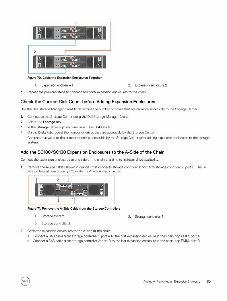
Figure 70. Cable the Expansion Enclosures Together
1. Expansion enclosure 1 2. Expansion enclosure 2
3. Repeat the previous steps to connect additional expansion enclosures to the chain.
Check the Current Disk Count before Adding Expansion Enclosures
Use the Dell Storage Manager Client to determine the number of drives that are currently accessible to the Storage Center.
1. Connect to the Storage Center using the Dell Storage Manager Client.
2. Select the Storage tab.
3. In the Storage tab navigation pane, select the Disks node.
4. On the Disks tab, record the number of drives that are accessible by the Storage Center.
Compare this value to the number of drives accessible by the Storage Center after adding expansion enclosures to the storage system.
Add the SC100/SC120 Expansion Enclosures to the A-Side of the Chain
Connect the expansion enclosures to one side of the chain at a time to maintain drive availability.
1. Remove the A-side cable (shown in orange) that connects storage controller 1: port A to storage controller 2: port B. The B-side cable continues to carry I/O while the A-side is disconnected.
Figure 71. Remove the A-Side Cable from the Storage Controllers
1. Storage system 2. Storage controller 1
3. Storage controller 2
2. Cable the expansion enclosures to the A-side of the chain.
a. Connect a SAS cable from storage controller 1: port A to the first expansion enclosure in the chain, top EMM, port A.b. Connect a SAS cable from storage controller 2: port B to the last expansion enclosure in the chain, top EMM, port B.
Adding or Removing an Expansion Enclosure 85
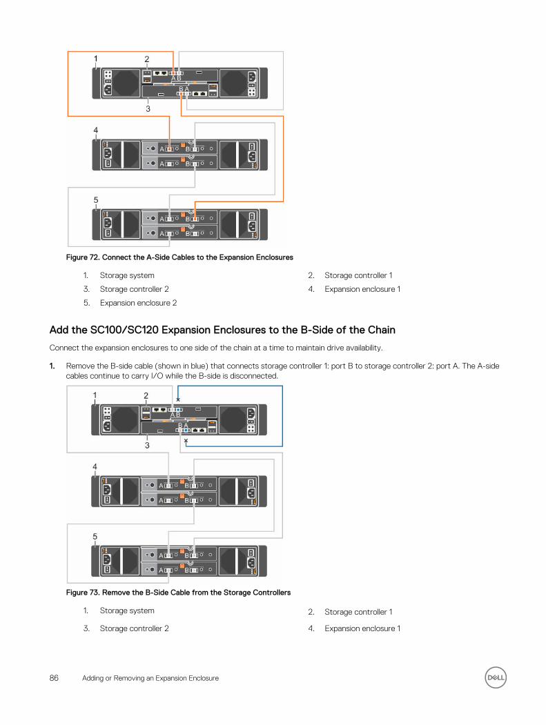
Figure 72. Connect the A-Side Cables to the Expansion Enclosures
1. Storage system 2. Storage controller 1
3. Storage controller 2 4. Expansion enclosure 1
5. Expansion enclosure 2
Add the SC100/SC120 Expansion Enclosures to the B-Side of the Chain
Connect the expansion enclosures to one side of the chain at a time to maintain drive availability.
1. Remove the B-side cable (shown in blue) that connects storage controller 1: port B to storage controller 2: port A. The A-side cables continue to carry I/O while the B-side is disconnected.
Figure 73. Remove the B-Side Cable from the Storage Controllers
1. Storage system 2. Storage controller 1
3. Storage controller 2 4. Expansion enclosure 1
86 Adding or Removing an Expansion Enclosure
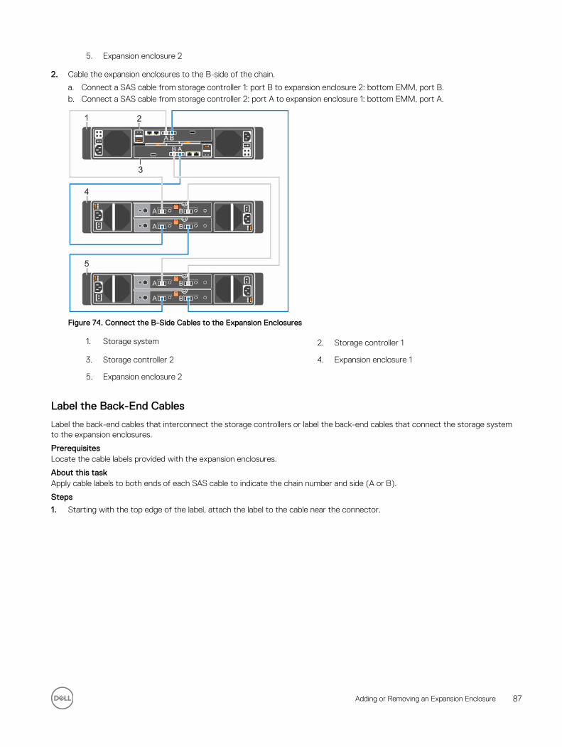
5. Expansion enclosure 2
2. Cable the expansion enclosures to the B-side of the chain.
a. Connect a SAS cable from storage controller 1: port B to expansion enclosure 2: bottom EMM, port B.b. Connect a SAS cable from storage controller 2: port A to expansion enclosure 1: bottom EMM, port A.
Figure 74. Connect the B-Side Cables to the Expansion Enclosures
1. Storage system 2. Storage controller 1
3. Storage controller 2 4. Expansion enclosure 1
5. Expansion enclosure 2
Label the Back-End Cables
Label the back-end cables that interconnect the storage controllers or label the back-end cables that connect the storage system to the expansion enclosures.
PrerequisitesLocate the cable labels provided with the expansion enclosures.
About this taskApply cable labels to both ends of each SAS cable to indicate the chain number and side (A or B).
Steps
1. Starting with the top edge of the label, attach the label to the cable near the connector.
Adding or Removing an Expansion Enclosure 87
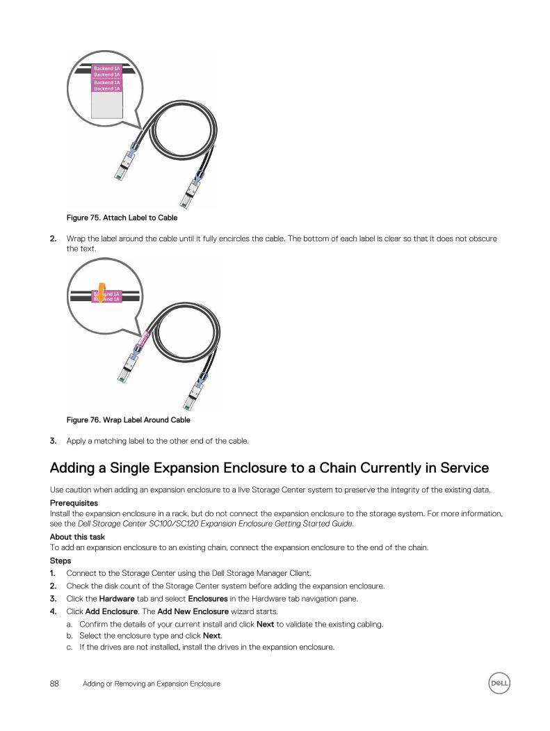
Figure 75. Attach Label to Cable
2. Wrap the label around the cable until it fully encircles the cable. The bottom of each label is clear so that it does not obscure the text.
Figure 76. Wrap Label Around Cable
3. Apply a matching label to the other end of the cable.
Adding a Single Expansion Enclosure to a Chain Currently in ServiceUse caution when adding an expansion enclosure to a live Storage Center system to preserve the integrity of the existing data.
PrerequisitesInstall the expansion enclosure in a rack, but do not connect the expansion enclosure to the storage system. For more information, see the Dell Storage Center SC100/SC120 Expansion Enclosure Getting Started Guide.
About this taskTo add an expansion enclosure to an existing chain, connect the expansion enclosure to the end of the chain.
Steps
1. Connect to the Storage Center using the Dell Storage Manager Client.
2. Check the disk count of the Storage Center system before adding the expansion enclosure.
3. Click the Hardware tab and select Enclosures in the Hardware tab navigation pane.
4. Click Add Enclosure. The Add New Enclosure wizard starts.
a. Confirm the details of your current install and click Next to validate the existing cabling.b. Select the enclosure type and click Next.c. If the drives are not installed, install the drives in the expansion enclosure.
88 Adding or Removing an Expansion Enclosure
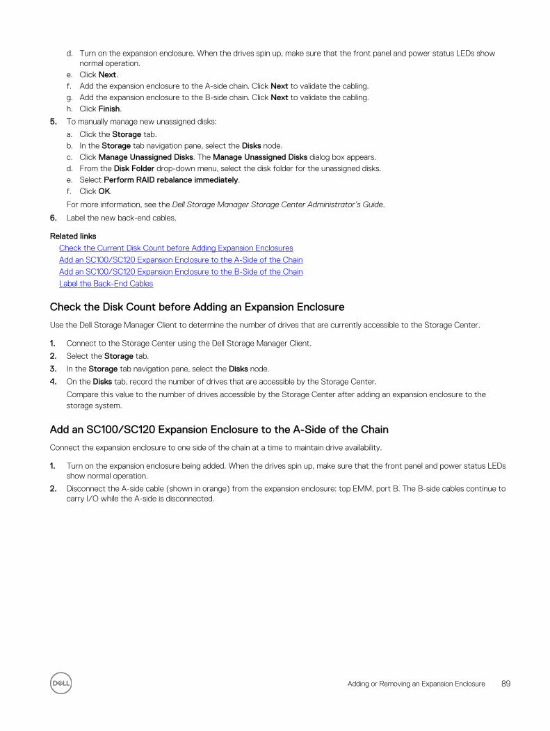
d. Turn on the expansion enclosure. When the drives spin up, make sure that the front panel and power status LEDs show normal operation.
e. Click Next.f. Add the expansion enclosure to the A-side chain. Click Next to validate the cabling.g. Add the expansion enclosure to the B-side chain. Click Next to validate the cabling.h. Click Finish.
5. To manually manage new unassigned disks:
a. Click the Storage tab.b. In the Storage tab navigation pane, select the Disks node.c. Click Manage Unassigned Disks. The Manage Unassigned Disks dialog box appears.d. From the Disk Folder drop-down menu, select the disk folder for the unassigned disks.e. Select Perform RAID rebalance immediately.f. Click OK.
For more information, see the Dell Storage Manager Storage Center Administrator’s Guide.
6. Label the new back-end cables.
Related links
Check the Current Disk Count before Adding Expansion Enclosures
Add an SC100/SC120 Expansion Enclosure to the A-Side of the Chain
Add an SC100/SC120 Expansion Enclosure to the B-Side of the Chain
Label the Back-End Cables
Check the Disk Count before Adding an Expansion Enclosure
Use the Dell Storage Manager Client to determine the number of drives that are currently accessible to the Storage Center.
1. Connect to the Storage Center using the Dell Storage Manager Client.
2. Select the Storage tab.
3. In the Storage tab navigation pane, select the Disks node.
4. On the Disks tab, record the number of drives that are accessible by the Storage Center.
Compare this value to the number of drives accessible by the Storage Center after adding an expansion enclosure to the storage system.
Add an SC100/SC120 Expansion Enclosure to the A-Side of the Chain
Connect the expansion enclosure to one side of the chain at a time to maintain drive availability.
1. Turn on the expansion enclosure being added. When the drives spin up, make sure that the front panel and power status LEDs show normal operation.
2. Disconnect the A-side cable (shown in orange) from the expansion enclosure: top EMM, port B. The B-side cables continue to carry I/O while the A-side is disconnected.
Adding or Removing an Expansion Enclosure 89
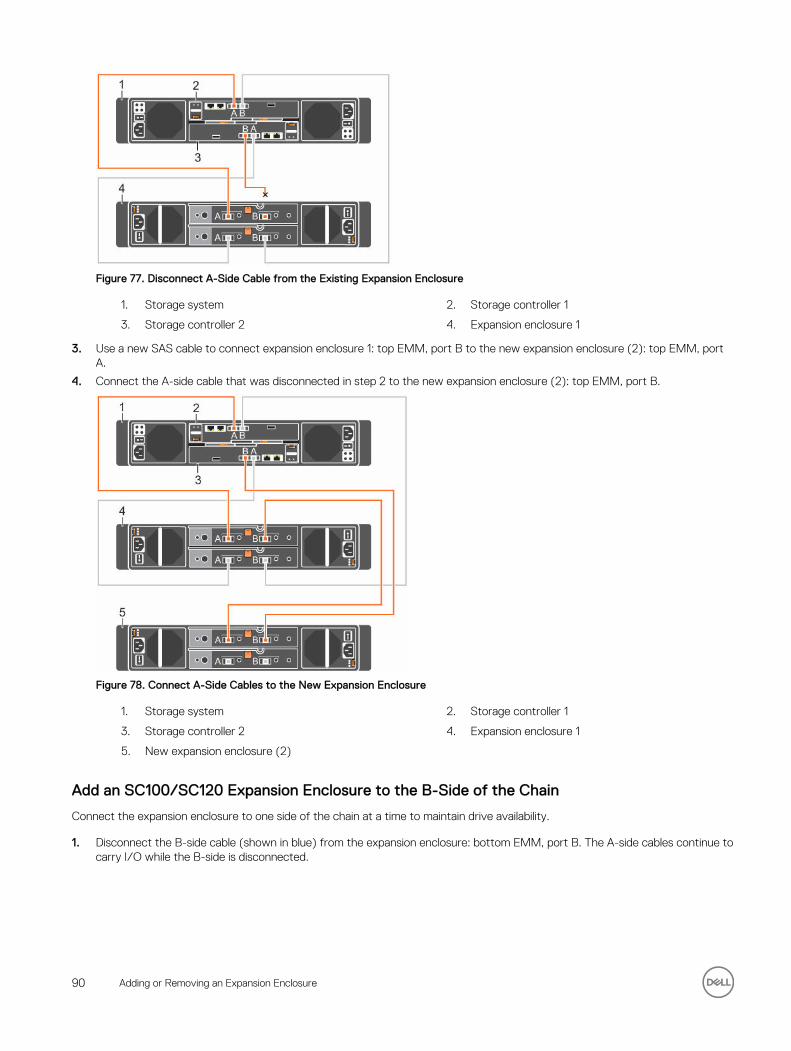
Figure 77. Disconnect A-Side Cable from the Existing Expansion Enclosure
1. Storage system 2. Storage controller 1
3. Storage controller 2 4. Expansion enclosure 1
3. Use a new SAS cable to connect expansion enclosure 1: top EMM, port B to the new expansion enclosure (2): top EMM, port A.
4. Connect the A-side cable that was disconnected in step 2 to the new expansion enclosure (2): top EMM, port B.
Figure 78. Connect A-Side Cables to the New Expansion Enclosure
1. Storage system 2. Storage controller 1
3. Storage controller 2 4. Expansion enclosure 1
5. New expansion enclosure (2)
Add an SC100/SC120 Expansion Enclosure to the B-Side of the Chain
Connect the expansion enclosure to one side of the chain at a time to maintain drive availability.
1. Disconnect the B-side cable (shown in blue) from the expansion enclosure: bottom EMM, port B. The A-side cables continue to carry I/O while the B-side is disconnected.
90 Adding or Removing an Expansion Enclosure
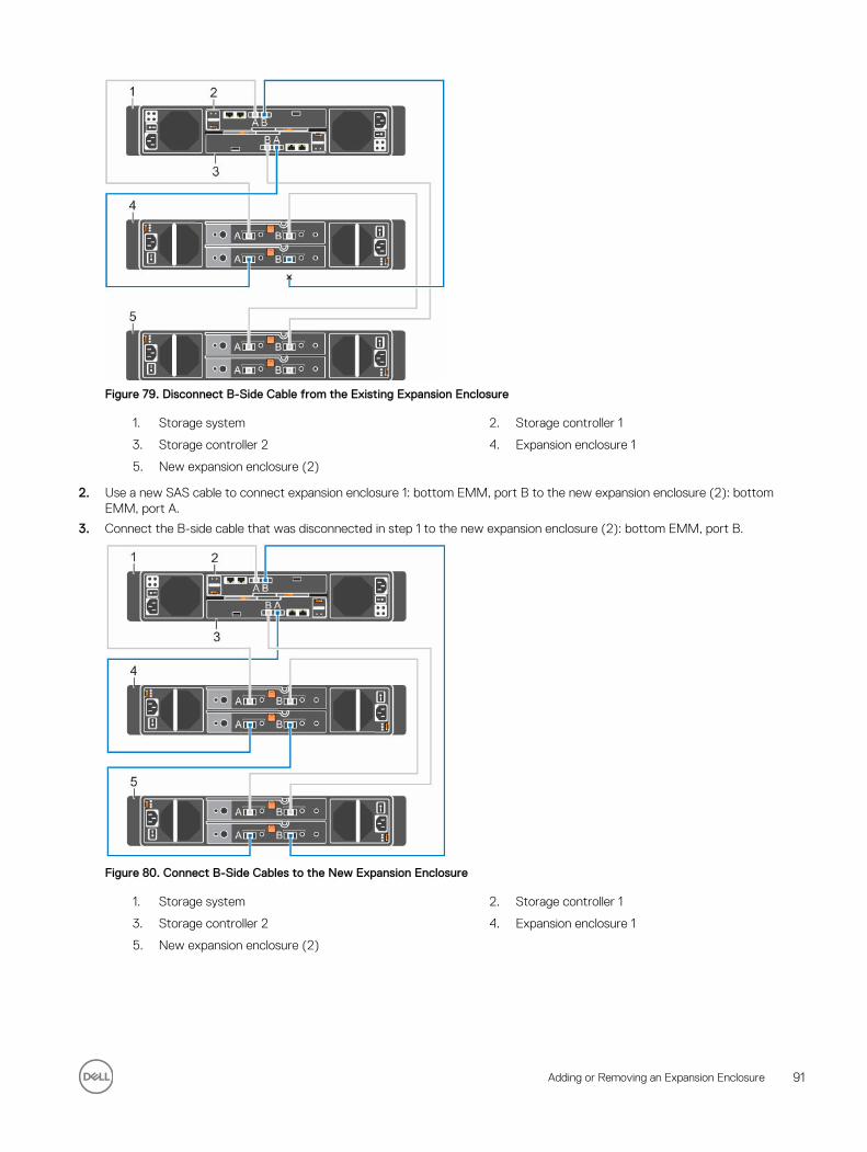
Figure 79. Disconnect B-Side Cable from the Existing Expansion Enclosure
1. Storage system 2. Storage controller 1
3. Storage controller 2 4. Expansion enclosure 1
5. New expansion enclosure (2)
2. Use a new SAS cable to connect expansion enclosure 1: bottom EMM, port B to the new expansion enclosure (2): bottom EMM, port A.
3. Connect the B-side cable that was disconnected in step 1 to the new expansion enclosure (2): bottom EMM, port B.
Figure 80. Connect B-Side Cables to the New Expansion Enclosure
1. Storage system 2. Storage controller 1
3. Storage controller 2 4. Expansion enclosure 1
5. New expansion enclosure (2)
Adding or Removing an Expansion Enclosure 91
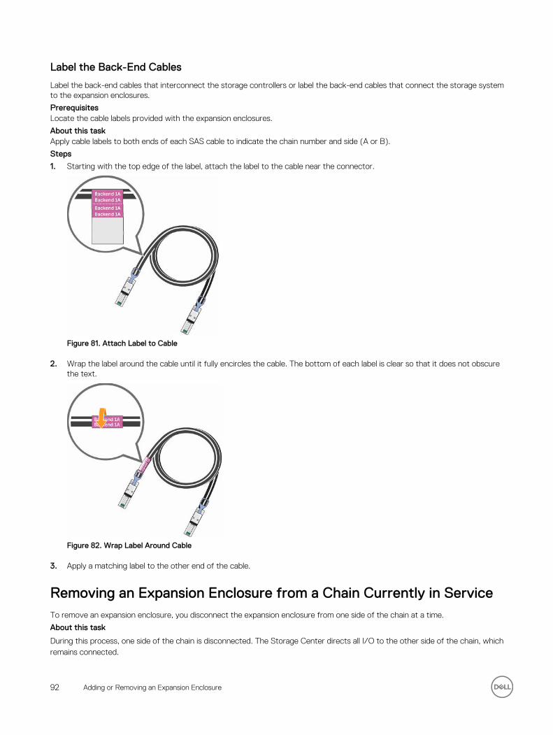
Label the Back-End Cables
Label the back-end cables that interconnect the storage controllers or label the back-end cables that connect the storage system to the expansion enclosures.
PrerequisitesLocate the cable labels provided with the expansion enclosures.
About this taskApply cable labels to both ends of each SAS cable to indicate the chain number and side (A or B).
Steps
1. Starting with the top edge of the label, attach the label to the cable near the connector.
Figure 81. Attach Label to Cable
2. Wrap the label around the cable until it fully encircles the cable. The bottom of each label is clear so that it does not obscure the text.
Figure 82. Wrap Label Around Cable
3. Apply a matching label to the other end of the cable.
Removing an Expansion Enclosure from a Chain Currently in ServiceTo remove an expansion enclosure, you disconnect the expansion enclosure from one side of the chain at a time.
About this task
During this process, one side of the chain is disconnected. The Storage Center directs all I/O to the other side of the chain, which remains connected.
92 Adding or Removing an Expansion Enclosure
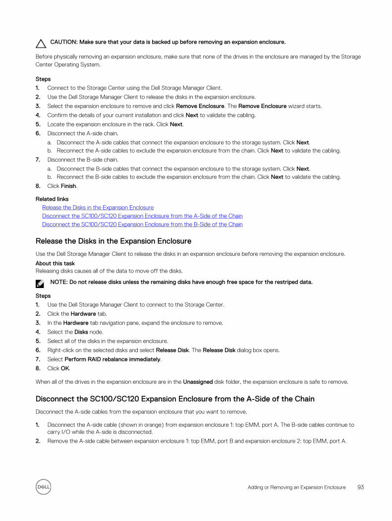
CAUTION: Make sure that your data is backed up before removing an expansion enclosure.
Before physically removing an expansion enclosure, make sure that none of the drives in the enclosure are managed by the Storage Center Operating System.
Steps
1. Connect to the Storage Center using the Dell Storage Manager Client.
2. Use the Dell Storage Manager Client to release the disks in the expansion enclosure.
3. Select the expansion enclosure to remove and click Remove Enclosure. The Remove Enclosure wizard starts.
4. Confirm the details of your current installation and click Next to validate the cabling.
5. Locate the expansion enclosure in the rack. Click Next.
6. Disconnect the A-side chain.
a. Disconnect the A-side cables that connect the expansion enclosure to the storage system. Click Next.b. Reconnect the A-side cables to exclude the expansion enclosure from the chain. Click Next to validate the cabling.
7. Disconnect the B-side chain.
a. Disconnect the B-side cables that connect the expansion enclosure to the storage system. Click Next.b. Reconnect the B-side cables to exclude the expansion enclosure from the chain. Click Next to validate the cabling.
8. Click Finish.
Related links
Release the Disks in the Expansion Enclosure
Disconnect the SC100/SC120 Expansion Enclosure from the A-Side of the Chain
Disconnect the SC100/SC120 Expansion Enclosure from the B-Side of the Chain
Release the Disks in the Expansion Enclosure
Use the Dell Storage Manager Client to release the disks in an expansion enclosure before removing the expansion enclosure.
About this taskReleasing disks causes all of the data to move off the disks.
NOTE: Do not release disks unless the remaining disks have enough free space for the restriped data.
Steps
1. Use the Dell Storage Manager Client to connect to the Storage Center.
2. Click the Hardware tab.
3. In the Hardware tab navigation pane, expand the enclosure to remove.
4. Select the Disks node.
5. Select all of the disks in the expansion enclosure.
6. Right-click on the selected disks and select Release Disk. The Release Disk dialog box opens.
7. Select Perform RAID rebalance immediately.
8. Click OK.
When all of the drives in the expansion enclosure are in the Unassigned disk folder, the expansion enclosure is safe to remove.
Disconnect the SC100/SC120 Expansion Enclosure from the A-Side of the Chain
Disconnect the A-side cables from the expansion enclosure that you want to remove.
1. Disconnect the A-side cable (shown in orange) from expansion enclosure 1: top EMM, port A. The B-side cables continue to carry I/O while the A-side is disconnected.
2. Remove the A-side cable between expansion enclosure 1: top EMM, port B and expansion enclosure 2: top EMM, port A.
Adding or Removing an Expansion Enclosure 93
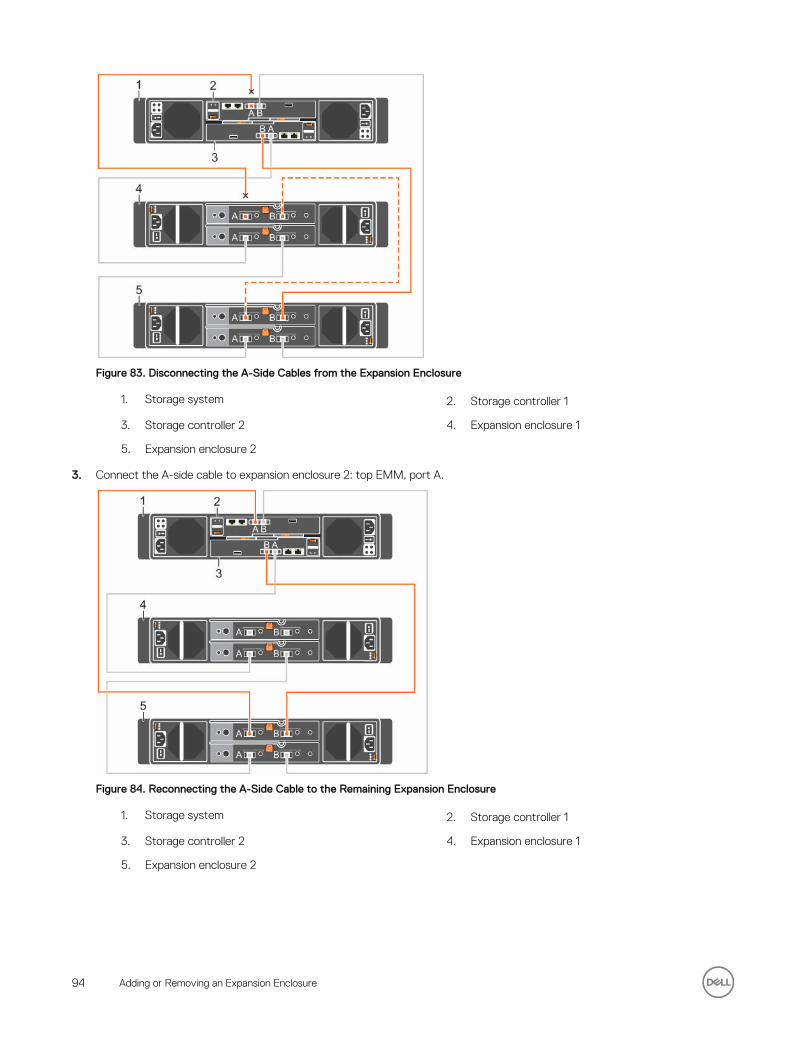
Figure 83. Disconnecting the A-Side Cables from the Expansion Enclosure
1. Storage system 2. Storage controller 1
3. Storage controller 2 4. Expansion enclosure 1
5. Expansion enclosure 2
3. Connect the A-side cable to expansion enclosure 2: top EMM, port A.
Figure 84. Reconnecting the A-Side Cable to the Remaining Expansion Enclosure
1. Storage system 2. Storage controller 1
3. Storage controller 2 4. Expansion enclosure 1
5. Expansion enclosure 2
94 Adding or Removing an Expansion Enclosure
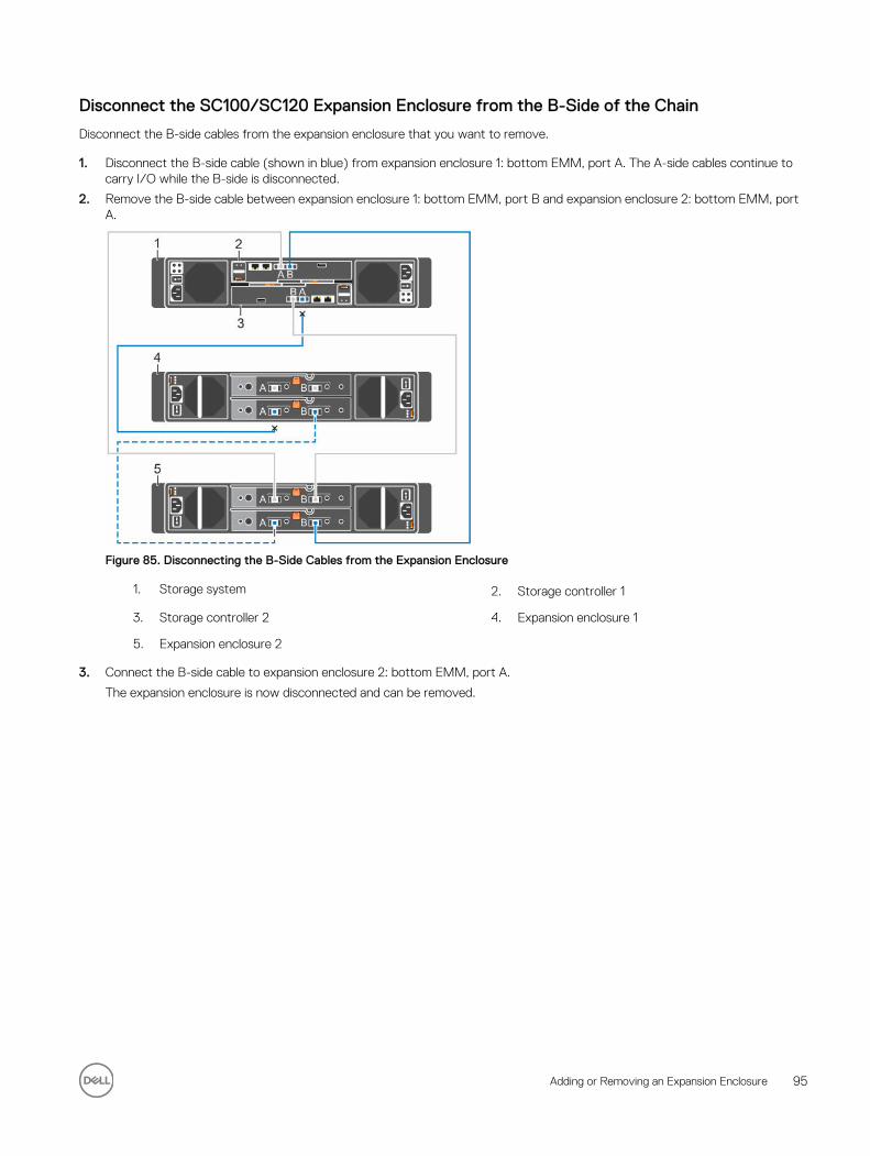
Disconnect the SC100/SC120 Expansion Enclosure from the B-Side of the Chain
Disconnect the B-side cables from the expansion enclosure that you want to remove.
1. Disconnect the B-side cable (shown in blue) from expansion enclosure 1: bottom EMM, port A. The A-side cables continue to carry I/O while the B-side is disconnected.
2. Remove the B-side cable between expansion enclosure 1: bottom EMM, port B and expansion enclosure 2: bottom EMM, port A.
Figure 85. Disconnecting the B-Side Cables from the Expansion Enclosure
1. Storage system 2. Storage controller 1
3. Storage controller 2 4. Expansion enclosure 1
5. Expansion enclosure 2
3. Connect the B-side cable to expansion enclosure 2: bottom EMM, port A.
The expansion enclosure is now disconnected and can be removed.
Adding or Removing an Expansion Enclosure 95
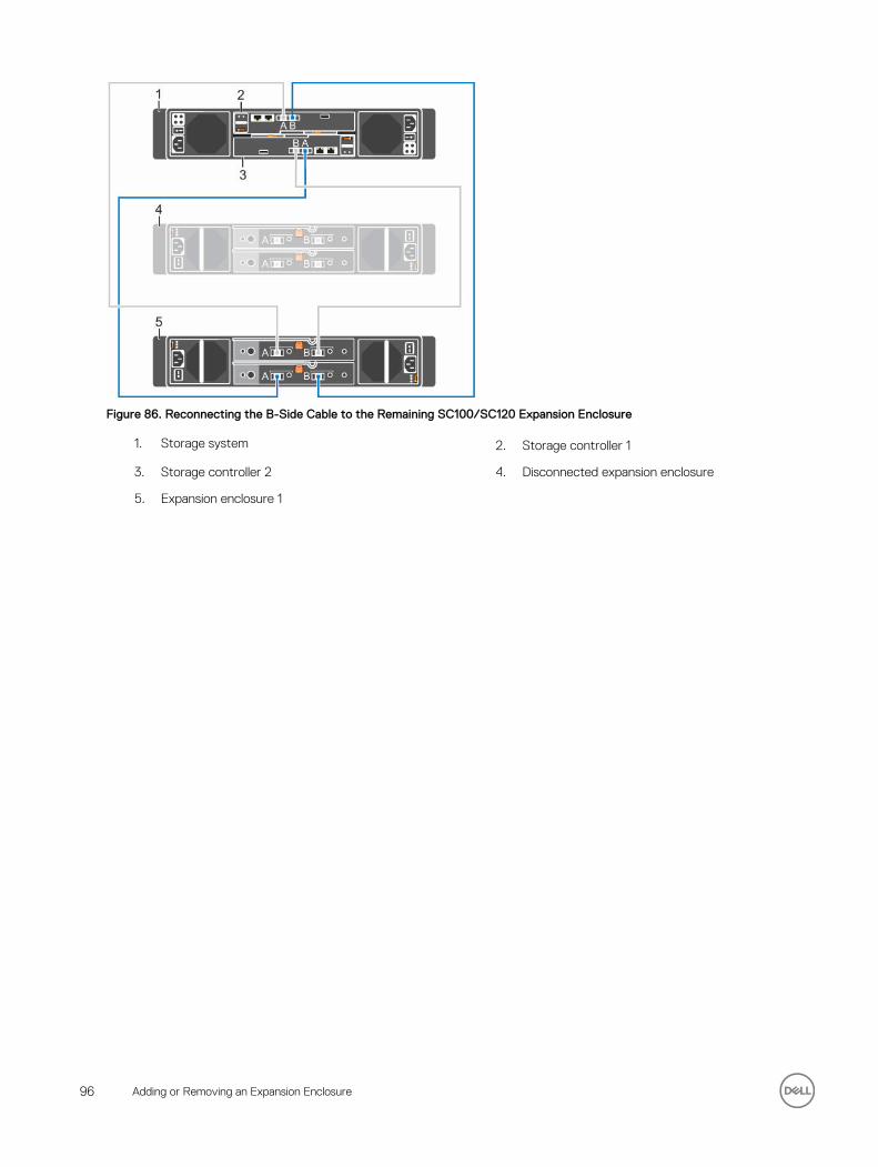
Figure 86. Reconnecting the B-Side Cable to the Remaining SC100/SC120 Expansion Enclosure
1. Storage system 2. Storage controller 1
3. Storage controller 2 4. Disconnected expansion enclosure
5. Expansion enclosure 1
96 Adding or Removing an Expansion Enclosure
BTroubleshooting Storage Center DeploymentThis section contains troubleshooting steps for common Storage Center deployment issues.
Troubleshooting Storage ControllersTo troubleshoot storage controllers:
1. Check the status of the storage controller using the Dell Storage Manager Client.
2. Check the position of the storage controllers. The storage controller with the lower HSN should be on the top, and the storage controller with the higher HSN should be on the bottom.
3. Check the pins and reseat the storage controller.
a. Remove the storage controller.b. Verify that the pins on the storage system backplane and the storage controller are not bent.c. Reinstall the storage controller.
4. Determine the status of the storage controller link status indicators. If the indicators are not green, check the cables.
a. Shut down the storage controller.b. Reseat the cables on the storage controller.c. Restart the storage controller.d. Recheck the link status indicators. If the link status indicators are not green, replace the cables.
Troubleshooting Hard DrivesTo troubleshoot hard drives:
1. Check the status of the hard drive using the Dell Storage Manager Client.
2. Determine the status of the hard drive indicators.
• If the hard drive status indicator blinks amber on 2 seconds / off 1 second, the hard drive has failed.
• If the hard drive status indicator is not lit, proceed to the next step.
3. Check the connectors and reseat the hard drive.
CAUTION: Perform this step only on unmanaged drives or after you confirm that the particular drive contains no user data. The Fault LED alone is not an indication that you can safely remove the drive.
a. Remove the hard drive.b. Check the hard drive and the backplane to ensure that the connectors are not damaged.c. Reinstall the hard drive. Make sure the hard drive makes contact with the backplane.
Troubleshooting Expansion EnclosuresTo troubleshoot expansion enclosures:
1. Check the status of the expansion enclosure using the Dell Storage Manager Client.
2. If an expansion enclosure and/or drives are missing from the Dell Storage Manager Client, you might need to check for and install Storage Center updates to use the expansion enclosure and/or drives.
3. If an expansion enclosure firmware update fails, check the back-end cabling and ensure that redundant connections are used.
Troubleshooting Storage Center Deployment 97