Embed Size (px)
Citation preview

INS
TRU
CTIO
NM
AN
UA
L
PART NO. A10355 - 04-06-05Copyright © 2005 Delta Machinery
ESPAÑOL: PÁGINA 21To learn more about DELTA MACHINERY visit our website at: www.deltamachinery.com.For Parts, Service, Warranty or other Assistance,
please call 1-800-223-7278 (In Canada call 1-800-463-3582).
20" Drill Press(Model 70-200)
2
TABLE OF CONTENTS
Read and understand all warnings and operating instructions before using any tool or equipment. Whenusing tools or equipment, basic safety precautions should always be followed to reduce the risk of personal injury.Improper operation, maintenance or modification of tools or equipment could result in serious injury and propertydamage. There are certain applications for which tools and equipment are designed. Delta Machinery stronglyrecommends that this product NOT be modified and/or used for any application other than for which it was designed.
If you have any questions relative to its application DO NOT use the product until you have written Delta Machineryand we have advised you.
Online contact form at www.deltamachinery.com
Postal Mail: Technical Service ManagerDelta Machinery4825 Highway 45 NorthJackson, TN 38305(IN CANADA: 505 SOUTHGATE DRIVE, GUELPH, ONTARIO N1H 6M7)
Information regarding the safe and proper operation of this tool is available from the following sources:
Power Tool Institute1300 Sumner Avenue, Cleveland, OH 44115-2851www.powertoolinstitute.org
National Safety Council1121 Spring Lake Drive, Itasca, IL 60143-3201
American National Standards Institute, 25 West 43rd Street, 4 floor, New York, NY 10036 www.ansi.orgANSI 01.1Safety Requirements for Woodworking Machines, and
the U.S. Department of Labor regulations www.osha.gov
IMPORTANT SAFETY INSTRUCTIONS
SAVE THESE INSTRUCTIONS!
IMPORTANT SAFETY INSTRUCTIONS . . . . . . . . . . . . . . . . . . . . . . . . . . . . . . . . . . . . . . . . . . . . . . . . . . . . . . . . . . .2SAFETY GUIDELINES . . . . . . . . . . . . . . . . . . . . . . . . . . . . . . . . . . . . . . . . . . . . . . . . . . . . . . . . . . . . . . . . . . . . . . . .3GENERAL SAFETY RULES . . . . . . . . . . . . . . . . . . . . . . . . . . . . . . . . . . . . . . . . . . . . . . . . . . . . . . . . . . . . . . . . . . . .4ADDITIONAL SPECIFIC SAFETY RULES . . . . . . . . . . . . . . . . . . . . . . . . . . . . . . . . . . . . . . . . . . . . . . . . . . . . . . . . .5FUNCTIONAL DESCRIPTION . . . . . . . . . . . . . . . . . . . . . . . . . . . . . . . . . . . . . . . . . . . . . . . . . . . . . . . . . . . . . . . . . .8CARTON CONTENTS . . . . . . . . . . . . . . . . . . . . . . . . . . . . . . . . . . . . . . . . . . . . . . . . . . . . . . . . . . . . . . . . . . . . . . . . .9ASSEMBLY . . . . . . . . . . . . . . . . . . . . . . . . . . . . . . . . . . . . . . . . . . . . . . . . . . . . . . . . . . . . . . . . . . . . . . . . . . . . . . . .10OPERATION . . . . . . . . . . . . . . . . . . . . . . . . . . . . . . . . . . . . . . . . . . . . . . . . . . . . . . . . . . . . . . . . . . . . . . . . . . . . . . .17TROUBLESHOOTING . . . . . . . . . . . . . . . . . . . . . . . . . . . . . . . . . . . . . . . . . . . . . . . . . . . . . . . . . . . . . . . . . . . . . . .19MAINTENANCE . . . . . . . . . . . . . . . . . . . . . . . . . . . . . . . . . . . . . . . . . . . . . . . . . . . . . . . . . . . . . . . . . . . . . . . . . . . . .20SERVICE . . . . . . . . . . . . . . . . . . . . . . . . . . . . . . . . . . . . . . . . . . . . . . . . . . . . . . . . . . . . . . . . . . . . . . . . . . . . . . . . . .20ACCESSORIES . . . . . . . . . . . . . . . . . . . . . . . . . . . . . . . . . . . . . . . . . . . . . . . . . . . . . . . . . . . . . . . . . . . . . . . . . . . .20WARRANTY . . . . . . . . . . . . . . . . . . . . . . . . . . . . . . . . . . . . . . . . . . . . . . . . . . . . . . . . . . . . . . . . . . . . . . . . . . . . . . . .20ESPAÑOL . . . . . . . . . . . . . . . . . . . . . . . . . . . . . . . . . . . . . . . . . . . . . . . . . . . . . . . . . . . . . . . . . . . . . . . . . . . . . . . . . .21SERVICE CENTER LOCATIONS . . . . . . . . . . . . . . . . . . . . . . . . . . . . . . . . . . . . . . . . . . . . . . . . . . . . . . . .back cover
3
Indicates an imminently hazardous situation which, if not avoided, will result in death or serious injury.
Indicates a potentially hazardous situation which, if not avoided, could result in death or serious injury.
Indicates a potentially hazardous situation which, if not avoided, may result in minor or moderate injury.
Used without the safety alert symbol indicates potentially hazardous situation which, if not avoided, mayresult in property damage.
It is important for you to read and understand this manual. The information it contains relates to protectingYOUR SAFETY and PREVENTING PROBLEMS. The symbols below are used to help you recognize thisinformation.
SAFETY GUIDELINES - DEFINITIONS
SOME DUST CREATED BY POWER SANDING, SAWING, GRINDING, DRILLING, AND OTHERCONSTRUCTION ACTIVITIES contains chemicals known to cause cancer, birth defects or other reproductive harm.Some examples of these chemicals are:· lead from lead-based paints,· crystalline silica from bricks and cement and other masonry products, and· arsenic and chromium from chemically-treated lumber. Your risk from these exposures varies, depending on how often you do this type of work. To reduce your exposure tothese chemicals: work in a well ventilated area, and work with approved safety equipment, always wear NIOSH/OSHAapproved, properly fitting face mask or respirator when using such tools.
CALIFORNIA PROPOSITION 65
4
GENERAL SAFETY RULES
READ AND UNDERSTAND ALL WARNINGS AND OPERATING INSTRUCTIONS BEFOREUSING THIS EQUIPMENT. Failure to follow all instructions listed below, may result in electric shock,fire, and/or serious personal injury or property damage.
IMPORTANT SAFETY INSTRUCTIONS
1. FOR YOUR OWN SAFETY, READ THE INSTRUCTIONMANUAL BEFORE OPERATING THE MACHINE.Learning the machine’s application, limitations, andspecific hazards will greatly minimize the possibility ofaccidents and injury.
2. WEAR EYE AND HEARING PROTECTION.ALWAYS USE SAFETY GLASSES. Everydayeyeglasses are NOT safety glasses. USE CERTIFIEDSAFETY EQUIPMENT. Eye protection equipmentshould comply with ANSI Z87.1 standards. Hearingequipment should comply with ANSI S3.19standards.
3. WEAR PROPER APPAREL. Do not wear looseclothing, gloves, neckties, rings, bracelets, or otherjewelry which may get caught in moving parts. Nonslipfootwear is recommended. Wear protective haircovering to contain long hair.
4. DO NOT USE THE MACHINE IN A DANGEROUSENVIRONMENT. The use of power tools in damp orwet locations or in rain can cause shock orelectrocution. Keep your work area well-lit to preventtripping or placing arms, hands, and fingers in danger.
5. MAINTAIN ALL TOOLS AND MACHINES IN PEAKCONDITION. Keep tools sharp and clean for best and safestperformance. Follow instructions for lubricating and changingaccessories. Poorly maintained tools and machines can furtherdamage the tool or machine and/or cause injury.
6. CHECK FOR DAMAGED PARTS. Before using themachine, check for any damaged parts. Check foralignment of moving parts, binding of moving parts,breakage of parts, and any other conditions that mayaffect its operation. A guard or any other part that isdamaged should be properly repaired or replaced.Damaged parts can cause further damage to themachine and/or injury.
7. KEEP THE WORK AREA CLEAN. Cluttered areas andbenches invite accidents.
8. KEEP CHILDREN AND VISITORS AWAY. Your shop is apotentially dangerous environment. Children and visitors canbe injured.
9. REDUCE THE RISK OF UNINTENTIONAL STARTING.Make sure that the switch is in the “OFF” positionbefore plugging in the power cord. In the event of apower failure, move the switch to the “OFF” position.An accidental start-up can cause injury.
10. USE THE GUARDS. Check to see that all guards arein place, secured, and working correctly to reducethe risk of injury.
11. REMOVE ADJUSTING KEYS AND WRENCHESBEFORE STARTING THE MACHINE. Tools, scrappieces, and other debris can be thrown at high speed,causing injury.
12. USE THE RIGHT MACHINE. Don’t force a machine oran attachment to do a job for which it was notdesigned. Damage to the machine and/or injury mayresult.
13. USE RECOMMENDED ACCESSORIES. The use ofaccessories and attachments not recommended by
Delta may cause damage to the machine or injury to theuser.
14. USE THE PROPER EXTENSION CORD. Make sureyour extension cord is in good condition. When usingan extension cord, be sure to use one heavy enough tocarry the current your product will draw. An undersizedcord will cause a drop in line voltage, resulting in loss ofpower and overheating. See the Extension Cord Chartfor the correct size depending on the cord length andnameplate ampere rating. If in doubt, use the nextheavier gauge. The smaller the gauge number, theheavier the cord.
15. SECURE THE WORKPIECE. Use clamps or a vise to holdthe workpiece when practical. Loss of control of aworkpiece can cause injury.
16. FEED THE WORKPIECE AGAINST THE DIRECTION OFTHE ROTATION OF THE BLADE, CUTTER, OR ABRASIVESURFACE. Feeding it from the other direction will causethe workpiece to be thrown out at high speed.
17. DON’T FORCE THE WORKPIECE ON THE MACHINE.Damage to the machine and/or injury may result.
18. DON’T OVERREACH. Loss of balance can make youfall into a working machine, causing injury.
19. NEVER STAND ON THE MACHINE. Injury could occur if thetool tips, or if you accidentally contact the cutting tool.
20. NEVER LEAVE THE MACHINE RUNNING UNATTENDED.TURN THE POWER OFF. Don’t leave the machine until itcomes to a complete stop. A child or visitor could be injured.
21. TURN THE MACHINE “OFF”, AND DISCONNECT THEMACHINE FROM THE POWER SOURCE before installingor removing accessories, before adjusting or changingset-ups, or when making repairs. An accidental start-upcan cause injury.
22. MAKE YOUR WORKSHOP CHILDPROOF WITHPADLOCKS, MASTER SWITCHES, OR BYREMOVING STARTER KEYS. The accidental start-upof a machine by a child or visitor could cause injury.
23. STAY ALERT, WATCH WHAT YOU ARE DOING, ANDUSE COMMON SENSE. DO NOT USE THEMACHINE WHEN YOU ARE TIRED OR UNDER THEINFLUENCE OF DRUGS, ALCOHOL, OR MEDICAT-ION. A moment of inattention while operating powertools may result in injury.
24. USE OF THIS TOOL CAN GENERATEAND DISBURSE DUST OR OTHER AIRBORNEPARTICLES, INCLUDING WOOD DUST,CRYSTALLINE SILICA DUST AND ASBESTOS DUST.Direct particles away from face and body. Alwaysoperate tool in well ventilated area and provide forproper dust removal. Use dust collection systemwherever possible. Exposure to the dust may causeserious and permanent respiratory or other injury,including silicosis (a serious lung disease), cancer, anddeath. Avoid breathing the dust, and avoid prolongedcontact with dust. Allowing dust to get into your mouthor eyes, or lay on your skin may promote absorption ofharmful material. Always use properly fittingNIOSH/OSHA approved respiratory protectionappropriate for the dust exposure, and wash exposedareas with soap and water.

5
ADDITIONAL SPECIFIC SAFETY RULES
FAILURE TO FOLLOW THESE RULES MAY RESULT IN SERIOUS INJURY.
1. DO NOT OPERATE THIS MACHINE until it iscompletely assembled and installed according tothe instructions. A machine incorrectly assembled cancause serious injury.
2. OBTAIN ADVICE from your supervisor, instructor,or another qualified person if you are notthoroughly familiar with the operation of thismachine. Knowledge is safety.
3. FOLLOW ALL WIRING CODES and recommendedelectrical connections to prevent shock or electrocution.
4. SECURE THE MACHINE TO A SUPPORTING SUR-FACE. Vibration can cause the machine to slide, walk,or tip over.
5. NEVER START THE MACHINE BEFORECLEARING THE TABLE OF ALL OBJECTS (tools,scrap pieces, etc.). Debris can be thrown at highspeed.
6. NEVER START THE MACHINE with the drill bit,cutting tool, or sanding drum against theworkpiece. Loss of control of the workpiece cancause serious injury.
7. PROPERLY LOCK THE DRILL BIT, CUTTING TOOL,OR SANDING DRUM IN THE CHUCK beforeoperating this machine.
8. REMOVE THE CHUCK KEY BEFORE STARTINGTHE MACHINE. The chuck key can be thrown outat a high speed.
9. TIGHTEN ALL LOCK HANDLES before starting themachine. Loss of control of the workpiece cancause serious injury.
10. USE ONLY DRILL BITS, CUTTING TOOLS,SANDING DRUMS, OR OTHER ACCESSORIESwith shank size recommended in your instructionmanual. The wrong size accessory can causedamage to the machine and/or serious injury.
11. USE ONLY DRILL BITS, CUTTING TOOLS, ORSANDING DRUMS that are not damaged.Damaged items can cause malfunctions that leadto injuries.
12. USE RECOMMENDED SPEEDS for all operations.Other speeds may cause the machine tomalfunction causing damage to the machineand/or serious injury.
13. AVOID AWKWARD OPERATIONS AND HANDPOSITIONS. A sudden slip could cause a hand tomove into the bit.
14. KEEP ARMS, HANDS, AND FINGERS away fromthe bit. Serious injury to the hand can occur.
15. HOLD THE WORKPIECE FIRMLY AGAINST THETABLE. Do not attempt to drill a workpiece thatdoes not have a flat surface against the table, orthat is not secured by a vise. Prevent theworkpiece from rotating by clamping it to the tableor by securing it against the drill press column.Loss of control of the workpiece can cause seriousinjury.
16. TURN THE MACHINE “OFF” AND WAIT FOR THEDRILL BIT, CUTTING TOOL, OR SANDING DRUMTO STOP TURNING prior to cleaning the work area,removing debris, removing or securing work-piece,or changing the angle of the table. A moving drillbit, cutting tool, or sanding drum can causeserious injury.
17. PROPERLY SUPPORT LONG OR WIDE work-pieces. Loss of control of the workpiece can causesevere injury.
18. NEVER PERFORM LAYOUT, ASSEMBLY ORSET-UP WORK on the table/work area when themachine is running. Serious injury can result.
19. TURN THE MACHINE “OFF”, disconnect themachine from the power source, and clean thetable/work area before leaving the machine. LOCKTHE SWITCH IN THE “OFF” POSITION toprevent unauthorized use. Someone else mightaccidentally start the machine and cause seriousinjury to themselves.
20. ADDITIONAL INFORMATION regarding the safeand proper operation of power tools (i.e. a safetyvideo) is available from the Power Tool Institute,1300 Sumner Avenue, Cleveland, OH 44115-2851(www.powertoolinstitute.com). Information is alsoavailable from the National Safety Council, 1121Spring Lake Drive, Itasca, IL 60143-3201. Pleaserefer to the American National Standards InstituteANSI 01.1 Safety Requirements for WoodworkingMachines and the U.S. Department of Labor OSHA1910.213 Regulations.
SAVE THESE INSTRUCTIONS.Refer to them often
and use them to instruct others.
6
A separate electrical circuit should be used for your machines. This circuit should not be less than #12 wire and shouldbe protected with a 20 Amp time lag fuse. If an extension cord is used, use only 3-wire extension cords which have 3-prong grounding type plugs and matching receptacle which will accept the machine’s plug. Before connecting themachine to the power line, make sure the switch (s) is in the “OFF” position and be sure that the electric current is ofthe same characteristics as indicated on the machine. All line connections should make good contact. Running on lowvoltage will damage the machine.
DO NOT EXPOSE THE MACHINE TO RAIN OR OPERATE THE MACHINE IN DAMP LOCATIONS.
Fig. A Fig. B
GROUNDED OUTLET BOX
CURRENTCARRYING
PRONGS
GROUNDING BLADEIS LONGEST OF THE 3 BLADES
GROUNDED OUTLET BOX
GROUNDINGMEANS
ADAPTER
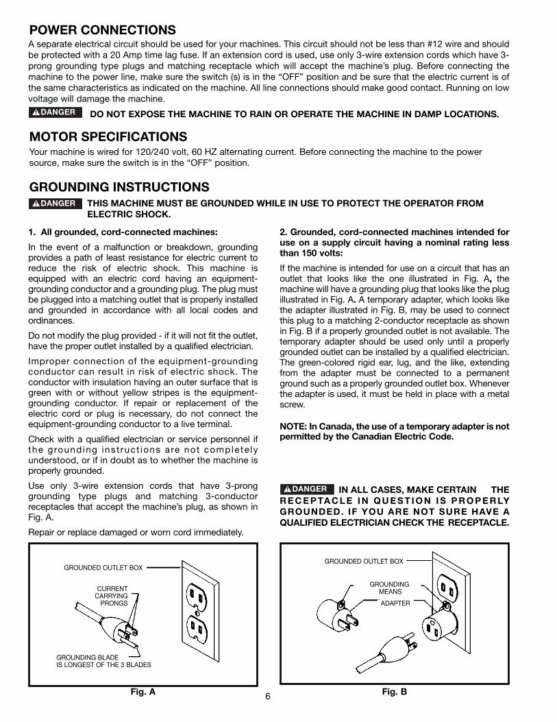
2. Grounded, cord-connected machines intended foruse on a supply circuit having a nominal rating lessthan 150 volts:
If the machine is intended for use on a circuit that has anoutlet that looks like the one illustrated in Fig. A, themachine will have a grounding plug that looks like the plugillustrated in Fig. A. A temporary adapter, which looks likethe adapter illustrated in Fig. B, may be used to connectthis plug to a matching 2-conductor receptacle as shownin Fig. B if a properly grounded outlet is not available. Thetemporary adapter should be used only until a properlygrounded outlet can be installed by a qualified electrician.The green-colored rigid ear, lug, and the like, extendingfrom the adapter must be connected to a permanentground such as a properly grounded outlet box. Wheneverthe adapter is used, it must be held in place with a metalscrew.
NOTE: In Canada, the use of a temporary adapter is notpermitted by the Canadian Electric Code.
IN ALL CASES, MAKE CERTAIN THER E C E P TA C L E I N Q U E S T I O N I S P R O P E R LYGROUNDED. IF YOU ARE NOT SURE HAVE AQUALIFIED ELECTRICIAN CHECK THE RECEPTACLE.
1. All grounded, cord-connected machines:
In the event of a malfunction or breakdown, groundingprovides a path of least resistance for electric current toreduce the risk of electric shock. This machine isequipped with an electric cord having an equipment-grounding conductor and a grounding plug. The plug mustbe plugged into a matching outlet that is properly installedand grounded in accordance with all local codes andordinances.
Do not modify the plug provided - if it will not fit the outlet,have the proper outlet installed by a qualified electrician.
Improper connection of the equipment-groundingconductor can result in risk of electric shock. Theconductor with insulation having an outer surface that isgreen with or without yellow stripes is the equipment-grounding conductor. If repair or replacement of theelectric cord or plug is necessary, do not connect theequipment-grounding conductor to a live terminal.
Check with a qualified electrician or service personnel ifthe grounding inst ruct ions are not complete lyunderstood, or if in doubt as to whether the machine isproperly grounded.
Use only 3-wire extension cords that have 3-pronggrounding type plugs and matching 3-conductorreceptacles that accept the machine’s plug, as shown inFig. A.
Repair or replace damaged or worn cord immediately.
POWER CONNECTIONS
MOTOR SPECIFICATIONSYour machine is wired for 120/240 volt, 60 HZ alternating current. Before connecting the machine to the powersource, make sure the switch is in the “OFF” position.
GROUNDING INSTRUCTIONSTHIS MACHINE MUST BE GROUNDED WHILE IN USE TO PROTECT THE OPERATOR FROMELECTRIC SHOCK.
7
EXTENSION CORDSUse proper extension cords. Make sure your extension cord is in good condition and is a 3-wire
extension cord which has a 3-prong grounding type plug and matching receptacle which will accept the machine’splug. When using an extension cord, be sure to use one heavy enough to carry the current of the machine. Anundersized cord will cause a drop in line voltage, resulting in loss of power and overheating. Fig. D-1 or D-2, showsthe correct gauge to use depending on the cord length. If in doubt, use the next heavier gauge. The smaller the gaugenumber, the heavier the cord.
Fig. D-1 Fig. D-2
MINIMUM GAUGE EXTENSION CORDRECOMMENDED SIZES FOR USE WITH STATIONARY ELECTRIC MACHINES
Ampere Total Length Gauge ofRating Volts of Cord in Feet Extension Cord
0-6 120 up to 25 18 AWG0-6 120 25-50 16 AWG0-6 120 50-100 16 AWG0-6 120 100-150 14 AWG
6-10 120 up to 25 18 AWG6-10 120 25-50 16 AWG6-10 120 50-100 14 AWG6-10 120 100-150 12 AWG
10-12 120 up to 25 16 AWG10-12 120 25-50 16 AWG10-12 120 50-100 14 AWG10-12 120 100-150 12 AWG
12-16 120 up to 25 14 AWG12-16 120 25-50 12 AWG12-16 120 GREATER THAN 50 FEET NOT RECOMMENDED
MINIMUM GAUGE EXTENSION CORDRECOMMENDED SIZES FOR USE WITH STATIONARY ELECTRIC MACHINES
Ampere Total Length Gauge ofRating Volts of Cord in Feet Extension Cord
0-6 240 up to 50 18 AWG0-6 240 50-100 16 AWG0-6 240 100-200 16 AWG0-6 240 200-300 14 AWG
6-10 240 up to 50 18 AWG6-10 240 50-100 16 AWG6-10 240 100-200 14 AWG6-10 240 200-300 12 AWG
10-12 240 up to 50 16 AWG10-12 240 50-100 16 AWG10-12 240 100-200 14 AWG10-12 240 200-300 12 AWG
12-16 240 up to 50 14 AWG12-16 240 50-100 12 AWG12-16 240 GREATER THAN 100 FEET NOT RECOMMENDED
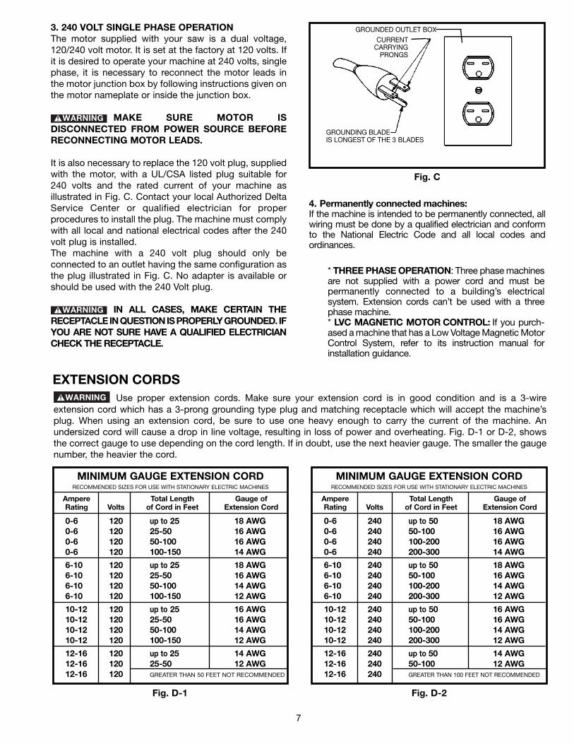
3. 240 VOLT SINGLE PHASE OPERATIONThe motor supplied with your saw is a dual voltage,120/240 volt motor. It is set at the factory at 120 volts. Ifit is desired to operate your machine at 240 volts, singlephase, it is necessary to reconnect the motor leads inthe motor junction box by following instructions given onthe motor nameplate or inside the junction box.
MAKE SURE MOTOR ISDISCONNECTED FROM POWER SOURCE BEFORERECONNECTING MOTOR LEADS.
It is also necessary to replace the 120 volt plug, suppliedwith the motor, with a UL/CSA listed plug suitable for240 volts and the rated current of your machine asillustrated in Fig. C. Contact your local Authorized DeltaService Center or qualified electrician for properprocedures to install the plug. The machine must complywith all local and national electrical codes after the 240volt plug is installed.The machine with a 240 volt plug should only beconnected to an outlet having the same configuration asthe plug illustrated in Fig. C. No adapter is available orshould be used with the 240 Volt plug.
IN ALL CASES, MAKE CERTAIN THERECEPTACLE IN QUESTION IS PROPERLY GROUNDED. IFYOU ARE NOT SURE HAVE A QUALIFIED ELECTRICIANCHECK THE RECEPTACLE.
Fig. C
GROUNDED OUTLET BOXCURRENT
CARRYINGPRONGS
GROUNDING BLADEIS LONGEST OF THE 3 BLADES
4. Permanently connected machines:If the machine is intended to be permanently connected, allwiring must be done by a qualified electrician and conformto the National Electric Code and all local codes andordinances.
* THREE PHASE OPERATION: Three phase machinesare not supplied with a power cord and must bepermanently connected to a building’s electricalsystem. Extension cords can’t be used with a threephase machine.* LVC MAGNETIC MOTOR CONTROL: If you purch-ased a machine that has a Low Voltage Magnetic MotorControl System, refer to its instruction manual forinstallation guidance.

8
FOREWORDThe Delta Model 70-200 Drill Press provides production capacity drilling and includes; 1 hp single phase 115/230 voltinduction motor, pulleys, belts, 0 - 5/8″ capacity chuck, 45 degree tilt table L/R, rack and pinion table raising mechanismand #3 Morse Taper spindle adaptor. A quick release motor mount makes changing the nine spindle speeds (150, 260,300, 440, 490, 540, 1150, and 2200 rpm) fast and easy.
FUNCTIONAL DESCRIPTION
NOTICE: THE PHOTO ON THE MANUAL COVER ILLUSTRATES THECURRENT PRODUCTION MODEL. ALL OTHER ILLUSTRATIONS CONTAINEDIN THE MANUAL ARE REPRESENTATIVE ONLY AND MAY NOT DEPICT THEACTUAL COLOR, LABELING OR ACCESSORIES AND ARE INTENDED TOILLUSTRATE TECHNIQUE ONLY.
9
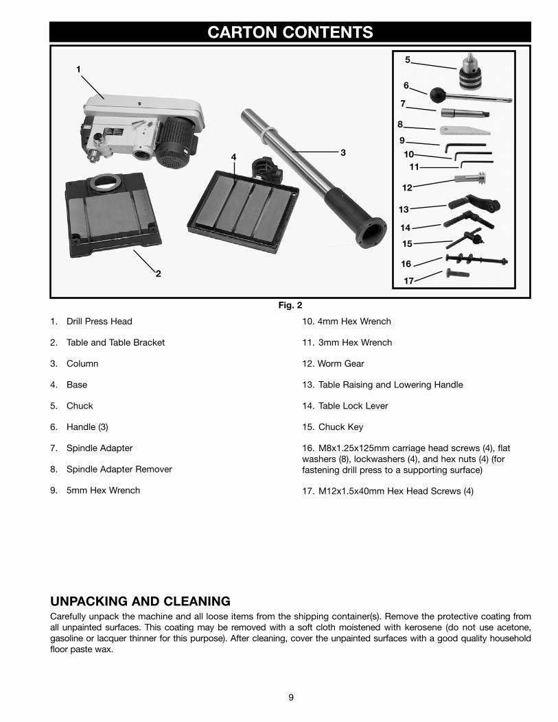
CARTON CONTENTS
UNPACKING AND CLEANINGCarefully unpack the machine and all loose items from the shipping container(s). Remove the protective coating fromall unpainted surfaces. This coating may be removed with a soft cloth moistened with kerosene (do not use acetone,gasoline or lacquer thinner for this purpose). After cleaning, cover the unpainted surfaces with a good quality householdfloor paste wax.
Fig. 2
1. Drill Press Head
2. Table and Table Bracket
3. Column
4. Base
5. Chuck
6. Handle (3)
7. Spindle Adapter
8. Spindle Adapter Remover
9. 5mm Hex Wrench
10. 4mm Hex Wrench
11. 3mm Hex Wrench
12. Worm Gear
13. Table Raising and Lowering Handle
14. Table Lock Lever
15. Chuck Key
16. M8x1.25x125mm carriage head screws (4), flatwashers (8), lockwashers (4), and hex nuts (4) (forfastening drill press to a supporting surface)
17. M12x1.5x40mm Hex Head Screws (4)
1
2
34
5
6
7
8
9
11
12
13
14
10
15
16
17
10
Fig. 16
Fig. 17
Fig. 18
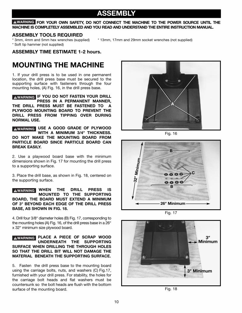
MOUNTING THE MACHINE1. If your drill press is to be used in one permanentlocation, the drill press base must be secured to thesupporting surface with fasteners through the fourmounting holes, (A) Fig. 16, in the drill press base.
IF YOU DO NOT FASTEN YOUR DRILLPRESS IN A PERMANENT MANNER,
THE DRILL PRESS MUST BE FASTENED TO APLYWOOD MOUNTING BOARD TO PREVENT THEDRILL PRESS FROM TIPPING OVER DURINGNORMAL USE.
USE A GOOD GRADE OF PLYWOODWITH A MINIMUM 3/4″″ THICKNESS.
DO NOT MAKE THE MOUNTING BOARD FROMPARTICLE BOARD SINCE PARTICLE BOARD CANBREAK EASILY.
2. Use a playwood board base with the minimumdimensions shown in Fig. 17 for mounting the drill pressto a supporting surface.
3. Place the drill base, as shown in Fig. 18, centered onthe supporting surface.
WHEN THE DRILL PRESS ISMOUNTED TO THE SUPPORTING
BOARD, THE BOARD MUST EXTEND A MINIMUMOF 3″″ BEYOND EACH EDGE OF THE DRILL PRESSBASE, AS SHOWN IN FIG. 18.
4. Drill four 3/8″ diameter holes (B) Fig. 17, corresponding tothe mounting holes (A) Fig. 16, of the drill press base in a 26″
x 32″ minimum size plywood board.
PLACE A PIECE OF SCRAP WOODUNDERNEATH THE SUPPORTING
SURFACE WHEN DRILLING THE THROUGH HOLESSO THAT THE DRILL BIT WILL NOT DAMAGE THEMATERIAL BENEATH THE SUPPORTING SURFACE.
5. Fasten the drill press base to the mounting boardusing the carriage bolts, nuts, and washers (C) Fig.17,furnished with your drill press. For stability, the holes forthe carriage bolt heads and flat washers must becountersunk so the bolt heads are flush with the bottomsurface of the mounting board.
A
B
B
26″″ Minimum
32″″
Min
imum
3″″
Minimum
3″″ Minimum
C
ASSEMBLYFOR YOUR OWN SAFETY, DO NOT CONNECT THE MACHINE TO THE POWER SOURCE UNTIL THE
MACHINE IS COMPLETELY ASSEMBLED AND YOU READ AND UNDERSTAND THE ENTIRE INSTRUCTION MANUAL.
ASSEMBLY TOOLS REQUIRED* 3mm, 4mm and 5mm hex wrenches (supplied) * 13mm, 17mm and 29mm socket wrenches (not supplied)* Soft tip hammer (not supplied)
ASSEMBLY TIME ESTIMATE 1-2 hours.
11
Fig. 2
Fig. 3
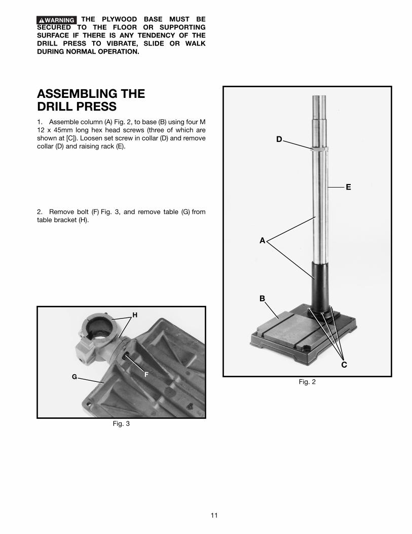
ASSEMBLING THEDRILL PRESS1. Assemble column (A) Fig. 2, to base (B) using four M12 x 45mm long hex head screws (three of which areshown at [C]). Loosen set screw in collar (D) and removecollar (D) and raising rack (E).
2. Remove bolt (F) Fig. 3, and remove table (G) fromtable bracket (H).
H
G F
B
C
A
E
D
THE PLYWOOD BASE MUST BESECURED TO THE FLOOR OR SUPPORTINGSURFACE IF THERE IS ANY TENDENCY OF THEDRILL PRESS TO VIBRATE, SLIDE OR WALKDURING NORMAL OPERATION.
12
Fig. 4
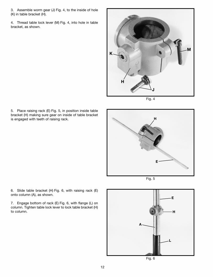
3. Assemble worm gear (J) Fig. 4, to the inside of hole(K) in table bracket (H).
4. Thread table lock lever (M) Fig. 4, into hole in tablebracket, as shown.
Fig. 5
Fig. 6
5. Place raising rack (E) Fig. 5, in position inside tablebracket (H) making sure gear on inside of table bracketis engaged with teeth of raising rack.
6. Slide table bracket (H) Fig. 6, with raising rack (E)onto column (A), as shown.
7. Engage bottom of rack (E) Fig. 6, with flange (L) oncolumn. Tighten table lock lever to lock table bracket (H)to column.
MK
H
J
H
E
E
H
A
L
13
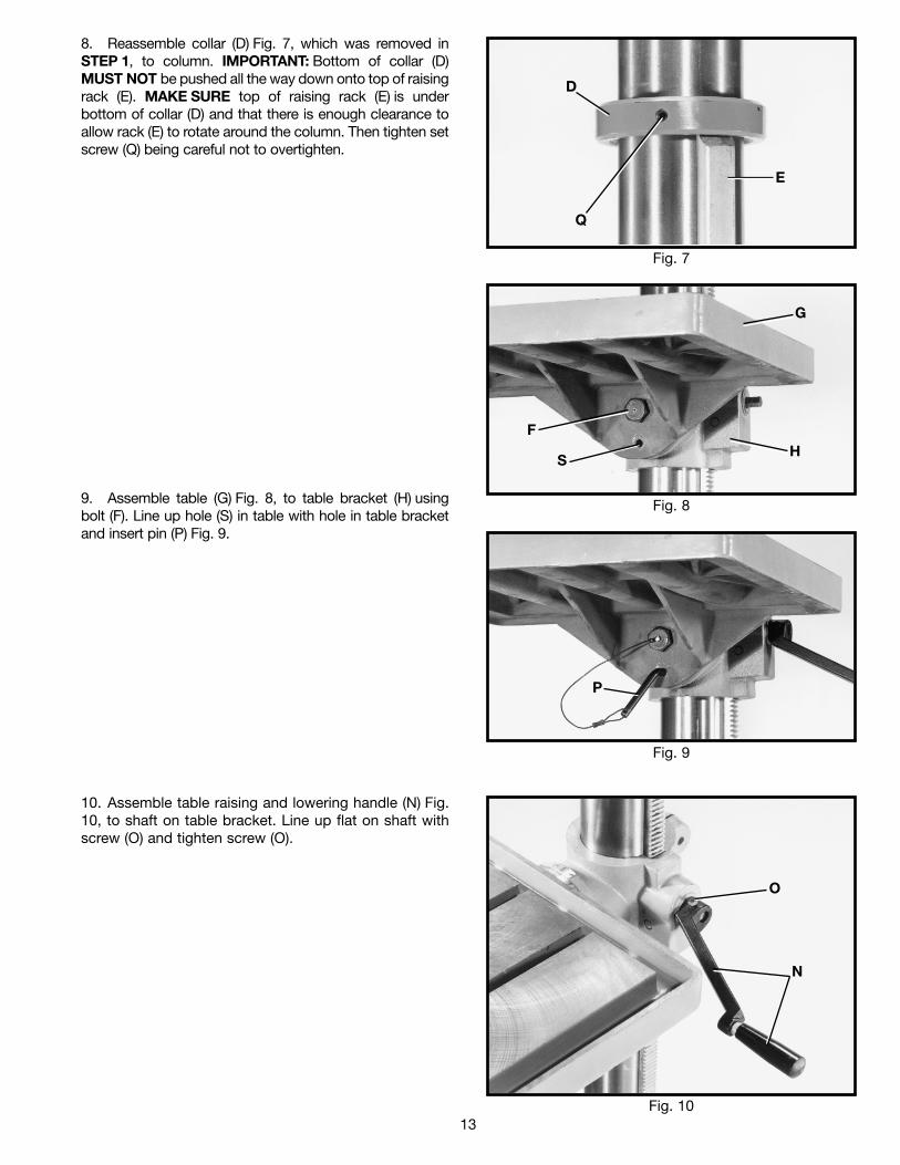
8. Reassemble collar (D) Fig. 7, which was removed inSTEP 1, to column. IMPORTANT: Bottom of collar (D)MUST NOT be pushed all the way down onto top of raisingrack (E). MAKE SURE top of raising rack (E) is underbottom of collar (D) and that there is enough clearance toallow rack (E) to rotate around the column. Then tighten setscrew (Q) being careful not to overtighten.
10. Assemble table raising and lowering handle (N) Fig.10, to shaft on table bracket. Line up flat on shaft withscrew (O) and tighten screw (O).
Fig. 10
Fig. 7
Fig. 8
Fig. 9
9. Assemble table (G) Fig. 8, to table bracket (H) usingbolt (F). Line up hole (S) in table with hole in table bracketand insert pin (P) Fig. 9.
D
Q
E
G
HS
F
P
O
N
14
Fig. 11
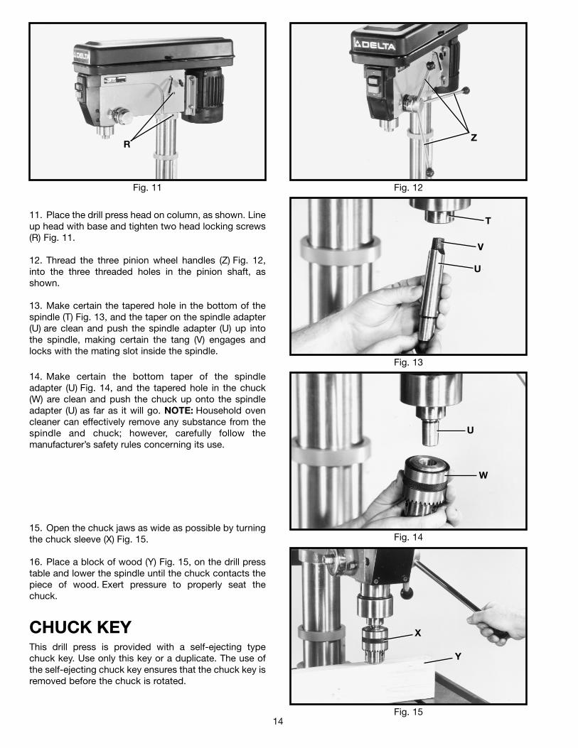
11. Place the drill press head on column, as shown. Lineup head with base and tighten two head locking screws(R) Fig. 11.
12. Thread the three pinion wheel handles (Z) Fig. 12,into the three threaded holes in the pinion shaft, asshown.
13. Make certain the tapered hole in the bottom of thespindle (T) Fig. 13, and the taper on the spindle adapter(U) are clean and push the spindle adapter (U) up intothe spindle, making certain the tang (V) engages andlocks with the mating slot inside the spindle.
Fig. 12
Fig. 13
Fig. 14
Fig. 15
14. Make certain the bottom taper of the spindleadapter (U) Fig. 14, and the tapered hole in the chuck(W) are clean and push the chuck up onto the spindleadapter (U) as far as it will go. NOTE: Household ovencleaner can effectively remove any substance from thespindle and chuck; however, carefully follow themanufacturer’s safety rules concerning its use.
15. Open the chuck jaws as wide as possible by turningthe chuck sleeve (X) Fig. 15.
16. Place a block of wood (Y) Fig. 15, on the drill presstable and lower the spindle until the chuck contacts thepiece of wood. Exert pressure to properly seat thechuck.
CHUCK KEYThis drill press is provided with a self-ejecting typechuck key. Use only this key or a duplicate. The use ofthe self-ejecting chuck key ensures that the chuck key isremoved before the chuck is rotated.
RZ
T
V
U
U
W
X
Y
15
OPERATIONAL CONTROLS AND ADJUSTMENTS
Fig. 23
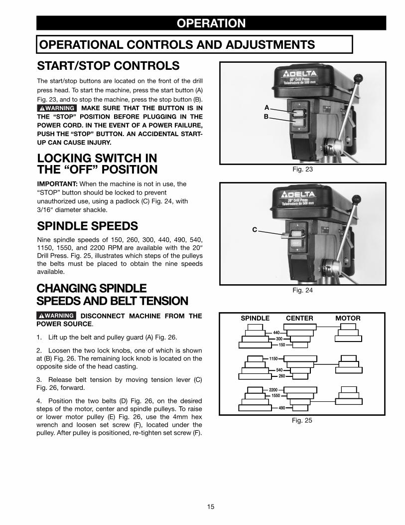
START/STOP CONTROLSThe start/stop buttons are located on the front of the drill
press head. To start the machine, press the start button (A)
Fig. 23, and to stop the machine, press the stop button (B).MAKE SURE THAT THE BUTTON IS IN
THE “STOP” POSITION BEFORE PLUGGING IN THEPOWER CORD. IN THE EVENT OF A POWER FAILURE,PUSH THE “STOP” BUTTON. AN ACCIDENTAL START-UP CAN CAUSE INJURY.
LOCKING SWITCH INTHE “OFF” POSITIONIMPORTANT: When the machine is not in use, the“STOP” button should be locked to preventunauthorized use, using a padlock (C) Fig. 24, with3/16″ diameter shackle.
Fig. 24
SPINDLE SPEEDSNine spindle speeds of 150, 260, 300, 440, 490, 540,1150, 1550, and 2200 RPM are available with the 20″
Drill Press. Fig. 25, illustrates which steps of the pulleysthe belts must be placed to obtain the nine speedsavailable.
AB
C
Fig. 25
SPINDLE CENTER MOTOR
440300
150
1150
540260
22001550
490
CHANGING SPINDLESPEEDS AND BELT TENSION
DISCONNECT MACHINE FROM THEPOWER SOURCE.
1. Lift up the belt and pulley guard (A) Fig. 26.
2. Loosen the two lock knobs, one of which is shownat (B) Fig. 26. The remaining lock knob is located on theopposite side of the head casting.
3. Release belt tension by moving tension lever (C)Fig. 26, forward.
4. Position the two belts (D) Fig. 26, on the desiredsteps of the motor, center and spindle pulleys. To raiseor lower motor pulley (E) Fig. 26, use the 4mm hexwrench and loosen set screw (F), located under thepulley. After pulley is positioned, re-tighten set screw (F).
OPERATION
16
Fig. 27
Fig. 28
Fig. 29
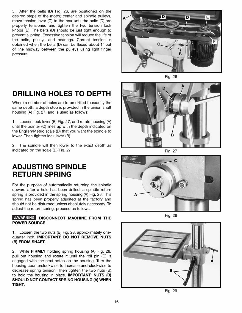
DRILLING HOLES TO DEPTHWhere a number of holes are to be drilled to exactly thesame depth, a depth stop is provided in the pinion shafthousing (A) Fig. 27, and is used as follows:
1. Loosen lock lever (B) Fig. 27, and rotate housing (A)until the pointer (C) lines up with the depth indicated onthe English/Metric scale (D) that you want the spindle tolower. Then tighten lock lever (B).
2. The spindle will then lower to the exact depth asindicated on the scale (D) Fig. 27
ADJUSTING SPINDLERETURN SPRINGFor the purpose of automatically returning the spindleupward after a hole has been drilled, a spindle returnspring is provided in the spring housing (A) Fig. 28. Thisspring has been properly adjusted at the factory andshould not be disturbed unless absolutely necessary. Toadjust the return spring, proceed as follows:
DISCONNECT MACHINE FROM THEPOWER SOURCE.
1. Loosen the two nuts (B) Fig. 28, approximately one-quarter inch. IMPORTANT: DO NOT REMOVE NUTS(B) FROM SHAFT.
2. While FIRMLY holding spring housing (A) Fig. 28,pull out housing and rotate it until the roll pin (C) isengaged with the next notch on the housing. Turn thehousing counterclockwise to increase and clockwise todecrease spring tension. Then tighten the two nuts (B) to hold the housing in place. IMPORTANT: NUTS (B)SHOULD NOT CONTACT SPRING HOUSING (A) WHENTIGHT.
B
C
AD
BA
C
B
A
Fig. 26
A
C
B
D D E
F
5. After the belts (D) Fig. 26, are positioned on thedesired steps of the motor, center and spindle pulleys,move tension lever (C) to the rear until the belts (D) areproperly tensioned and tighten the two tension lockknobs (B). The belts (D) should be just tight enough toprevent slipping. Excessive tension will reduce the life ofthe belts, pulleys and bearings. Correct tension isobtained when the belts (D) can be flexed about 1″ outof line midway between the pulleys using light fingerpressure.
17
Fig. 30
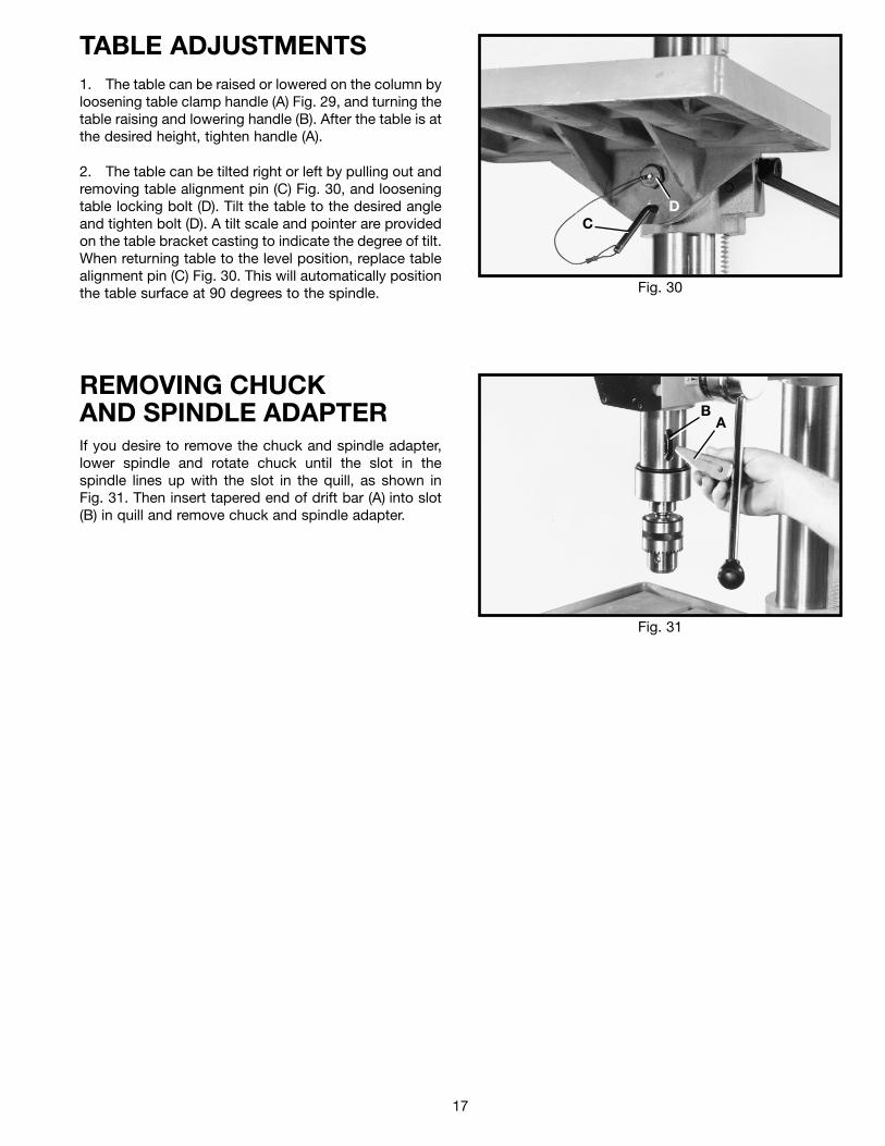
TABLE ADJUSTMENTS1. The table can be raised or lowered on the column byloosening table clamp handle (A) Fig. 29, and turning thetable raising and lowering handle (B). After the table is atthe desired height, tighten handle (A).
2. The table can be tilted right or left by pulling out andremoving table alignment pin (C) Fig. 30, and looseningtable locking bolt (D). Tilt the table to the desired angleand tighten bolt (D). A tilt scale and pointer are providedon the table bracket casting to indicate the degree of tilt.When returning table to the level position, replace tablealignment pin (C) Fig. 30. This will automatically positionthe table surface at 90 degrees to the spindle.
CD
Fig. 31
REMOVING CHUCKAND SPINDLE ADAPTERIf you desire to remove the chuck and spindle adapter,lower spindle and rotate chuck until the slot in thespindle lines up with the slot in the quill, as shown inFig. 31. Then insert tapered end of drift bar (A) into slot(B) in quill and remove chuck and spindle adapter.
BA
18
BORING IN WOODTwist drills, although intended for metal drilling, may also be used for boring holes in wood. However, machine spurbits are generally preferred for working in wood; they cut a square bottom hole and are designed for removal of woodchips. Do not use hand bits which have a screw tip; at drill press speeds they turn into the wood so rapidly as to liftthe work off the table and whirl it.
For through boring, line up the table so that the bit will enter the center hole to avoid damage. Scribe a vertical line onthe front of the column and a matchmark on the table bracket, so that the table can be clamped in the center positionat any height.
Feed slowly when the bit is about to cut through the wood to prevent splintering the bottom face. Use a scrap pieceof wood for a base block under the work. This helps to reduce splintering and protects the point of the bit.
NOTE: Your Drill Press should be used with drill bits 5/8″″ or less in diameter.
The following directions will give the inexperienced operator a start on common drill press operations. Use scrapmaterial for practice to get a feel of the machine before attempting regular work.
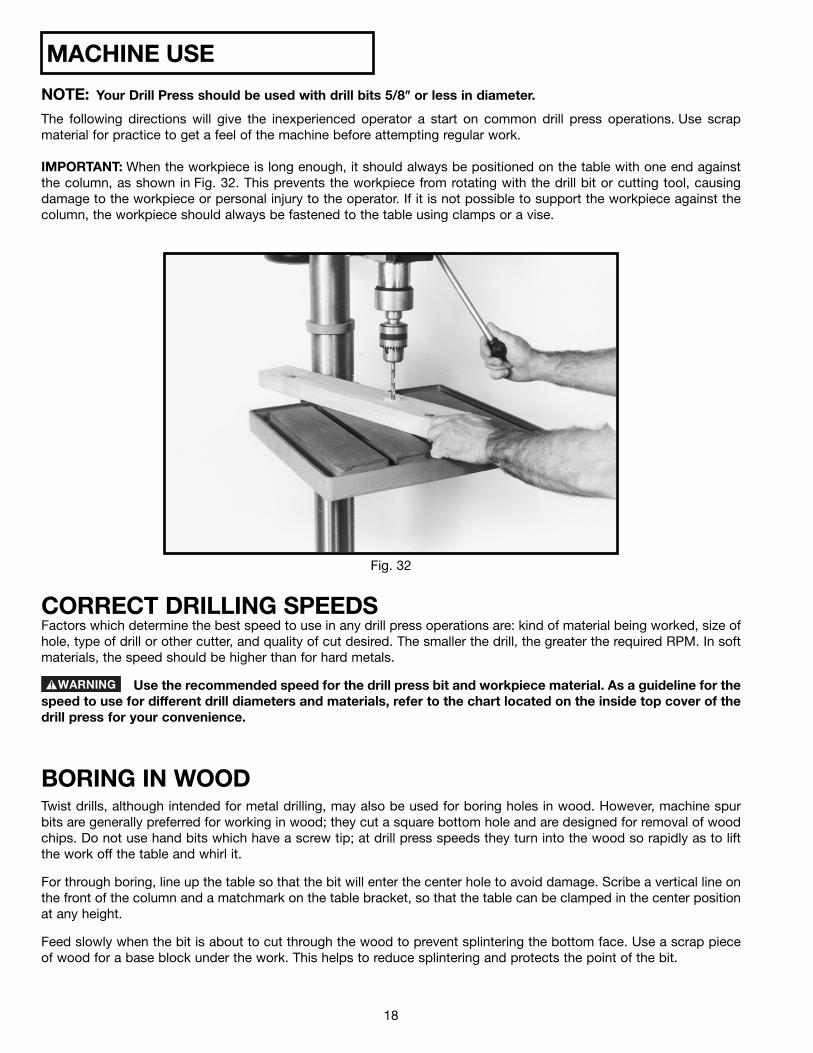
IMPORTANT: When the workpiece is long enough, it should always be positioned on the table with one end againstthe column, as shown in Fig. 32. This prevents the workpiece from rotating with the drill bit or cutting tool, causingdamage to the workpiece or personal injury to the operator. If it is not possible to support the workpiece against thecolumn, the workpiece should always be fastened to the table using clamps or a vise.
Fig. 32
CORRECT DRILLING SPEEDSFactors which determine the best speed to use in any drill press operations are: kind of material being worked, size ofhole, type of drill or other cutter, and quality of cut desired. The smaller the drill, the greater the required RPM. In softmaterials, the speed should be higher than for hard metals.
Use the recommended speed for the drill press bit and workpiece material. As a guideline for thespeed to use for different drill diameters and materials, refer to the chart located on the inside top cover of thedrill press for your convenience.
MACHINE USE
19
DRILLING METALUse clamps to hold the work when drilling in metal. The work should never be held in the bare hand; the lips of the drillmay seize the work at any time, especially when breaking through the stock. If the workpiece is whirled out of theoperator’s hand, he may be injured. In any case, the drill will be broken when the work strikes the column.
The work must be clamped firmly while drilling; any tilting, twisting or shifting results not only in a rough hole, but alsoincreases drill breakage. For flat work, lay the piece on a wooden base and clamp itfirmly down against the table to prevent it from turning. If the piece is of irregular shape and cannot be laid flat on thetable, it should be securely blocked and clamped.
TROUBLESHOOTINGFor assistance with your machine, visit our website at www.deltamachinery.com for a list of service centers or callthe DELTA Machinery help line at 1-800-223-7278 (In Canada call 1-800-463-3582).
MAINTENANCEKEEP MACHINE CLEANPeriodically blow out all air passages with dry compressedair. All plastic parts should be cleaned with a soft dampcloth. NEVER use solvents to clean plastic parts. They couldpossibly dissolve or otherwise damage the material.
Wear ANSI Z87.1 safety glasses whileusing compressed air.
FAILURE TO STARTShould your machine fail to start, check to make sure theprongs on the cord plug are making good contact in theoutlet. Also, check for blown fuses or open circuit breakersin the line.
LUBRICATIONApply household floor paste wax to the machine table andextension table or other work surface weekly.
PROTECTING CAST IRON FROM RUST
To clean and protect cast iron tables from rust, you willneed the following materials: 1 pushblock from a jointer,1 sheet of medium Scotch-Brite™ Blending Hand Pad, 1can of WD-40®, 1 can of degreaser, 1 can of TopCote®
Aerosol. Apply the WD-40 and polish the table surfacewith the Scotch-Brite pad using the pushblock as aholddown. Degrease the table, then apply the TopCote®
accordingly.

20
PARTS, SERVICE OR WARRANTY ASSISTANCEAll Delta Machines and accessories are manufactured to high quality standards and are serviced by a networkof Porter-Cable • Delta Factory Service Centers and Delta Authorized Service Stations. To obtain additionalinformation regarding your Delta quality product or to obtain parts, service, warranty assistance, or the locationof the nearest service outlet, please call 1-800-223-7278 (In Canada call 1-800-463-3582).
A complete line of accessories is available from your Delta Supplier, Porter-Cable • Delta Factory Service Centers,and Delta Authorized Service Stations. Please visit our Web Site www.deltamachinery.com for a catalog orfor the name of your nearest supplier.
Since accessories other than those offered by Delta have not been tested with this product, use of such accessories could be hazardous. For safest operation, only Delta recommended accessories should be used with this product.
ACCESSORIES
Two Year Limited New Product WarrantyDelta will repair or replace, at its expense and at its option, any new Delta machine, machine part, or machine accessorywhich in normal use has proven to be defective in workmanship or material, provided that the customer returns the productprepaid to a Delta factory service center or authorized service station with proof of purchase of the product within twoyears and provides Delta with reasonable opportunity to verify the alleged defect by inspection. For all refurbished Deltaproduct, the warranty period is 180 days. Delta may require that electric motors be returned prepaid to a motormanufacturer’s authorized station for inspection and repair or replacement. Delta will not be responsible for any asserteddefect which has resulted from normal wear, misuse, abuse or repair or alteration made or specifically authorized byanyone other than an authorized Delta service facility or representative. Under no circumstances will Delta be liable forincidental or consequential damages resulting from defective products. This warranty is Delta’s sole warranty and setsforth the customer’s exclusive remedy, with respect to defective products; all other warranties, express or implied, whetherof merchantability, fitness for purpose, or otherwise, are expressly disclaimed by Delta.
SERVICE
WARRANTY
The following are trademarks of PORTER-CABLE • DELTA (Las siguientes son marcas registradas de PORTER-CABLE • DELTA S.A.) (Les marquessuivantes sont des marques de fabriquant de la PORTER-CABLE • DELTA): Auto-Set®, BAMMER®, B.O.S.S.®, Builder’s Saw®, Contractor’s Saw®,Contractor’s Saw II™, Delta®, DELTACRAFT®, DELTAGRAM™, Delta Series 2000™, DURATRONIC™, Emc²™, FLEX®, Flying Chips™, FRAME SAW®,Grip Vac™, Homecraft®, INNOVATION THAT WORKS®, Jet-Lock®, JETSTREAM®, ‘kickstand®, LASERLOC®, MICRO-SET®, Micro-Set®, MIDI LATHE®,MORTEN™, NETWORK™, OMNIJIG®, POCKET CUTTER®, PORTA-BAND®, PORTA-PLANE®, PORTER-CABLE®&(design), PORTER-CABLE®PROFESSIONAL POWER TOOLS, PORTER-CABLE REDEFINING PERFORMANCE™, Posi-Matic®, Q-3®&(design), QUICKSAND®&(design),QUICKSET™, QUICKSET II®, QUICKSET PLUS™, RIPTIDE™&(design), SAFE GUARD II®, SAFE-LOC®, Sanding Center®, SANDTRAP®&(design), SAWBOSS®, Sawbuck™, Sidekick®, SPEED-BLOC®, SPEEDMATIC®, SPEEDTRONIC®, STAIR EASE®, The American Woodshop®&(design), The LumberCompany®&(design), THE PROFESSIONAL EDGE®, THE PROFESSIONAL SELECT®, THIN-LINE™, TIGER®, TIGER CUB®, TIGER SAW®,TORQBUSTER®, TORQ-BUSTER®, TRU-MATCH™, TWIN-LITE®, UNIGUARD®, Unifence®, UNIFEEDER™, Unihead®, Uniplane™, Unirip®, Unisaw®,Univise®, Versa-Feeder®, VERSA-PLANE® , WHISPER SERIES®, WOODWORKER’S CHOICE™. Trademarks noted with ™ and ® are registered in the United States Patent and Trademark Office and may also be registered in other countries. LasMarcas Registradas con el signo de ™ y ® son registradas por la Oficina de Registros y Patentes de los Estados Unidos y también pueden estarregistradas en otros países.
PORTER-CABLE • DELTA SERVICE CENTERS(CENTROS DE SERVICIO DE PORTER-CABLE • DELTA)
Parts and Repair Service for Porter-Cable • Delta Machinery are Available at These Locations(Obtenga Refaccion de Partes o Servicio para su Herramienta en los Siguientes Centros de Porter-Cable • Delta)
Authorized Service Stations are located in many large cities. Telephone 800-438-2486 or 731-541-6042 for assistance locating one.Parts and accessories for Porter-Cable·Delta products should be obtained by contacting any Porter-Cable·Delta Distributor, AuthorizedService Center, or Porter-Cable·Delta Factory Service Center. If you do not have access to any of these, call 800-223-7278 and you willbe directed to the nearest Porter-Cable·Delta Factory Service Center. Las Estaciones de Servicio Autorizadas están ubicadas en muchasgrandes ciudades. Llame al 800-438-2486 ó al 731-541-6042 para obtener asistencia a fin de localizar una. Las piezas y los accesoriospara los productos Porter-Cable·Delta deben obtenerse poniéndose en contacto con cualquier distribuidor Porter-Cable·Delta, Centrode Servicio Autorizado o Centro de Servicio de Fábrica Porter-Cable·Delta. Si no tiene acceso a ninguna de estas opciones, llame al800-223-7278 y le dirigirán al Centro de Servicio de Fábrica Porter-Cable·Delta más cercano.
ARIZONAPhoenix 85013-29064501 N. 7th Ave.Phone: (602) 279-6414Fax: (602) 279-5470
CALIFORNIAOntario 91761 (Los Angeles)3949A East Guasti RoadPhone: (909) 390-5555Fax: (909) 390-5554
San Diego 921117290 Clairemont Mesa Blvd.Phone: (858) 279-2011Fax: (858) 279-0362
San Leandro 94577 (Oakland)3039 Teagarden StreetPhone: (510) 357-9762Fax: (510) 357-7939
COLORADODenver 80223700 West Mississippi Ave.Phone: (303) 922-8325Fax: (303) 922-0245
FLORIDADavie 33314 (Miami)4343 South State Rd. 7 (441)Unit #107Phone: (954) 321-6635Fax: (954) 321-6638
Tampa 336344909 West Waters Ave.Phone: (813) 884-0434Fax: (813) 888-5997
GEORGIAForest Park 30297 (Atlanta)5442 Frontage Road,Suite 112Phone: (404) 608-0006Fax: (404) 608-1123
ILLINOISAddison 60101 (Chicago)400 South Rohlwing Rd.Phone: (630) 424-8805Fax: (630) 424-8895
Woodridge 60517 (Chicago)2033 West 75th StreetPhone: (630) 910-9200Fax: (630) 910-0360
KANSASOverland Park 662149201 Quivira RoadPhone: (913) 495-4330Fax: (913) 495-4378
MARYLANDElkridge 21075 (Baltimore)7397-102 Washington Blvd.Phone: (410) 799-9394Fax: (410) 799-9398
MASSACHUSETTSFranklin 02038 (Boston)Franklin Industrial Park101E Constitution Blvd.Phone: (508) 520-8802Fax: (508) 528-8089
MICHIGANMadison Heights 48071 (Detroit)30475 Stephenson HighwayPhone: (248) 597-5000Fax: (248) 597-5004MINNESOTAEden Prairie 553449709 Valley View RoadPhone: (952) 884-9191Fax: (952) 884-3750
MISSOURISt. Louis 6314611477 Page Service DrivePhone: (314) 997-9100Fax: (314) 997-9183
NEW YORKFlushing 11365-1595 (N.Y.C.)175-25 Horace Harding Expwy.Phone: (718) 225-2040Fax: (718) 423-9619
NORTH CAROLINACharlotte 282709129 Monroe Road, Suite 115Phone: (704) 841-1176Fax: (704) 708-4625
OHIOColumbus 432291948 Schrock RoadPhone: (614) 895-3112Fax: (614) 895-3187
Cleveland 441258001 Sweet Valley Drive Unit #19Phone: (216) 447-9030Fax: (216) 447-3097
OREGONPortland 9723014811 North East Airport WayPhone: (503) 255-6556Fax: (503) 255-6543
PENNSYLVANIAWillow Grove 19090(Philadelphia)520 North York RoadPhone: (215) 658-1430Fax: (215) 658-1433
TEXASCarrollton 75006 (Dallas)1300 Interstate 35 N, Suite 112Phone: (972) 446-2996Fax: (972) 446-8157
Houston 77022-2122536 East Tidwell Rd.Phone: (713) 692-7111Fax: (713) 692-1107
WASHINGTONAuburn 98001(Seattle)3320 West Valley HWY, NorthBuilding D, Suite 111Phone: (253) 333-8353Fax: (253) 333-9613
PC7.2-0105-149
CANADIAN PORTER-CABLE • DELTA SERVICE CENTERSALBERTABay 6, 2520-23rd St. N.E.Calgary, AlbertaT2E 8L2Phone: (403) 735-6166Fax: (403) 735-6144
BRITISH COLUMBIA8520 Baxter PlaceBurnaby, B.C.V5A 4T8Phone: (604) 420-0102Fax: (604) 420-3522
MANITOBA1699 Dublin AvenueWinnipeg, ManitobaR3H 0H2Phone: (204) 633-9259Fax: (204) 632-1976
ONTARIO505 Southgate DriveGuelph, OntarioN1H 6M7Phone: (519) 767-4132Fax: (519) 767-4131
QUÉBEC1515 ave.St-Jean Baptiste, Suite 160Québec, QuébecG2E 5E2Phone: (418) 877-7112Fax: (418) 877-7123
1447, BeginSt-Laurent, (Montréal),QuébecH4R 1V8Phone: (514) 336-8772Fax: (514) 336-3505