Embed Size (px)
Citation preview
DELTA Venlighedsvej 4
2970 Hørsholm
Denmark
Tel. +45 72 19 40 00
Fax +45 72 19 40 01
www.delta.dk
VAT No. 12275110
This report is issued under the rules of DANAK (Danish Accreditat ion) and ILAC (Internat ional Laboratory Accreditat ion Cooperat ion) including its MRA (Mutual Recognit ion Arrangement). Further information can be found at www.danak.dk and www.i lac.org. The report must not be reproduced, except in ful l, without the written approval of DELTA.
DELTA Test Report
Version m
TEST Reg. no. 19
Type approval testing of Engine Controller M2500 Performed for Selco A/S DANAK-1910664 Project no.: A506392 Page 1 of 68 including 6 annexes 15 October 2009
DANAK-1910664 DELTA-A506392 Page 2 of 68
HFR/lko
Title Type approval testing of Engine Controller M2500
Test object 1 pcs. Engine Controller M2500 Part no. M2500.0010
Detailed information is given in Chapter 2.
The test object was received on August 3 2009.
Report no. DANAK-1910664
Project no. A506392
Test period 3 August - 13 October 2009
Client Selco A/S Betonvej 10 4000 Roskilde Denmark
Tel.: +45 70 26 11 22
Contact person Mr Jesper Højland E-mail: [email protected]
Manufacturer Selco A/S
Specifications IACS E10: Rev. 5, Dec 2006. Test Specification for Type Approval”. Test specification applicable, but not confined to, all equipment used for: - Control, protection and safety; - internal communication.”
IEC 60945: Fourth edition, 2002 “Maritime navigation and radio communication equipment and systems - General requirements - Methods of testing and required test results.”
EN 50263: 1999. Electromagnetic compatibility (EMC) Product standard measuring relays and protection equipment.
Results No malfunctions were detected. The criteria for compliance are listed in Section 3.2.
Test personnel Henrik Egeberg Nielsen Raqia Ibrahim Khalil Poul Terkelsen Carsten Kiørboe
DANAK-1910664 DELTA-A506392 Page 3 of 68
HFR/lko
Date 15 October 2009
Project manager
Henrik Funding Raun, B.Sc.E.E. DELTA
Responsible
Susanne Otto, B.Sc.E.E., B.Com (Org.) DELTA
DANAK-1910664 DELTA-A506392 Page 4 of 68
HFR/lko
Table of contents Page
1. Summary of test 6 1.1 Test requirements 6 1.2 Conclusion 7
2. Test object 8 2.1 Test object 8 2.2 Auxiliary equipment 8
3. General test conditions 9 3.1 Test setup 9 3.2 Criteria for compliance 9 3.3 Functional test 9 3.4 Standard environment 10 3.5 Test sequence 10
4. Test and results 11 4.1 Visual inspection and performance test 11 4.2 Power supply failure 11 4.3 Power supply variations (permanent) 12 4.4 Reverse polarity 12 4.5 Low temperature (cold) 13 4.6 Dry heat 13 4.7 Damp heat, cyclic 14 4.8 Insulation resistance 15 4.9 High voltage 16 4.10 Resonance search (4 g) 16 4.11 Endurance - sinusoidal vibration 17 4.12 Electrostatic discharge 18 4.13 Radiated radio frequency interference 19 4.14 Conducted low frequency interference 20 4.15 Conducted radio frequency interference 20 4.16 Fast transients (burst) 21 4.17 Burst 1 MHz 22 4.18 Slow transients (surge) 23 4.19 Radiated emissions 24 4.20 Conducted emissions 25 4.21 Compass safe distance 26 4.22 Enclosure protection, IP 2X 27 4.23 Rated power frequency magnetic field 27
DANAK-1910664 DELTA-A506392 Page 5 of 68
HFR/lko
Annex 1 List of instruments 28
Annex 2 Photos 32
Annex 3 Test record sheets - Conducted emissions 42
Annex 4 Test record sheets - Radiated emissions 51
Annex 5 Measurement curves - Vibration 56
Annex 6 Test setup and functional test procedure (from Client) (This annex is informative and not part of the accredited report) 66
DANAK-1910664 DELTA-A506392 Page 6 of 68
HFR/lko
1. Summary of test
1.1 Test requirements
The following tests were carried out as agreed with the client.
Test Test method Visual inspection and performance test IEC 60945:2002, IACS E10:2006 Power supply failure IEC 60945:2002, IACS E10:2006 Power supply variations IEC 60945:2002, IACS E10:2006 Reverse polarity IEC 60945:2002 Low temperature (cold) IEC 60068-2-1:2007 Dry heat IEC 60068-2-2:2007 Damp heat (cyclic) IEC 60068-2-30:2005 Insulation resistance IACS E10:2006 High voltage IACS E10:2006 Vibration (resonance search) IEC 60068-2-6:2007 Vibration (sinusoidal) IEC 60068-2-6:2007 Electrostatic discharges IEC 61000-4-2:2001 Radiated radio frequency interference IEC 61000-4-3:2006 Conducted low frequency interference IEC 61000-4-16:1998 Conducted radio frequency interference IEC 61000-4-6:2007 Electrical fast transients (burst) IEC 61000-4-4:2004 Burst 1 MHz EN 50263:1999 Slow transients (surge) IEC 61000-4-5:2005 Radiated emissions CISPR 16-2-3:2006 Conducted emissions CISPR16-2-1:2008 Acoustic noise and signals IEC 60945:2002 Compass safe distance IEC 60945:2002 Enclosure protection, IP 2X IEC 60529:2001 Rated power frequency magnetic field IEC 61000-4-8:2001
DANAK-1910664 DELTA-A506392 Page 7 of 68
HFR/lko
1.2 Conclusion
The test object mentioned in this report meets the relevant requirements of the standards stated below.
• IACS E10:2006
• IEC 60945:2002
• EN 50263:1999
The test results relate only to the object tested.
DANAK-1910664 DELTA-A506392 Page 8 of 68
HFR/lko
2. Test object
2.1 Test object
Test object 2.1.1
Name of test object Engine Controller Model / type M2500 Part no. M2500.0010 Serial no. 429886 Manufacturer Selco A/S Supply voltage 24 VDC Comments -
2.2 Auxiliary equipment
Auxiliary equipment 2.2.1
Name of auxiliary equipment Engine Controller Model / type M2500 Part no. M2500.0010 Serial no. 429887 Manufacturer Selco A/S Supply voltage 24 VDC Comments -
DANAK-1910664 DELTA-A506392 Page 9 of 68
HFR/lko
3. General test conditions
3.1 Test setup
A drawing of the test setup is enclosed in Annex 6.
3.2 Criteria for compliance
No change of the actual operational states of the test object is allowed. However, temporary change is allowed during the power supply failure test.
In addition, the following generic acceptance criteria for compliance were in force during the EMC immunity testing:
• Performance Criterion A: (For continuous phenomena): The EUT shall continue to operate as intended during and after the test. No degradation of performance or loss of function is allowed as defined in the relevant equipment standard and in the technical specification published by the manufacturer.
• Performance Criterion B: (For transient phenomena): The EUT shall continue to operate as intended after the tests. No degradation of performance or loss of function is allowed as defined in the technical specification published by the manufacturer. During the test, degradation or loss of function or performance which is self-recoverable is, however, allowed but no change of actual operating state or stored data is allowed.
• Performance Criterion C: Temporary degradation or loss of function or performance is allowed during and after the test, provided the function is self-recoverable, or can be restored by the operation of the controls as defined in the relevant equipment standard and in the technical specification published by the manufacturer.
3.3 Functional test
A functional test was performed before, during (if specified) and after each test. The functional test was carried out in accordance with the functional test procedure provided by the customer.
The functional test procedure is given in Annex 6.
DANAK-1910664 DELTA-A506392 Page 10 of 68
HFR/lko
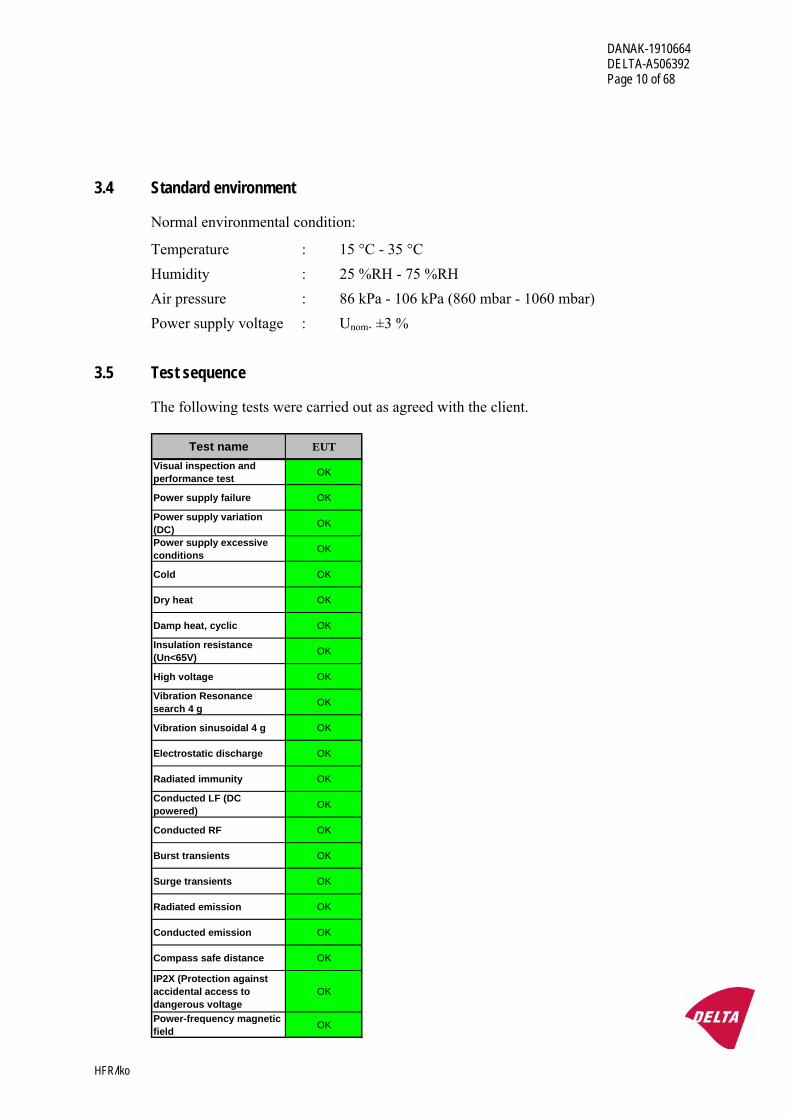
3.4 Standard environment
Normal environmental condition:
Temperature : 15 °C - 35 °C Humidity : 25 %RH - 75 %RH Air pressure : 86 kPa - 106 kPa (860 mbar - 1060 mbar) Power supply voltage : Unom. ±3 %
3.5 Test sequence
The following tests were carried out as agreed with the client.
Test name EUTVisual inspection and performance test OK
Power supply failure OK
Power supply variation (DC) OK
Power supply excessive conditions OK
Cold OK
Dry heat OK
Damp heat, cyclic OK
Insulation resistance (Un<65V) OK
High voltage OK
Vibration Resonance search 4 g OK
Vibration sinusoidal 4 g OK
Electrostatic discharge OK
Radiated immunity OK
Conducted LF (DC powered) OK
Conducted RF OK
Burst transients OK
Surge transients OK
Radiated emission OK
Conducted emission OK
Compass safe distance OK
IP2X (Protection against accidental access to dangerous voltage
OK
Power-frequency magnetic field OK
DANAK-1910664 DELTA-A506392 Page 11 of 68
HFR/lko
4. Test and results
4.1 Visual inspection and performance test
Specification & Test method
IACS E10, Test No. 1 and 2.
IEC 60945, clause 4.2.
Procedure
The conformance to drawings and the functional performance are demonstrated to the society surveyors present at DELTA during the type approval testing.
The functional test is also demonstrated.
Results
The conformance to drawings and the functional performance, including the functional test procedure, was demonstrated to the society surveyors after completion of the type approval testing, if requested.
4.2 Power supply failure
Specification & Test method
IACS E10, Test No. 3.
IEC 60945, clause 10.8.
Procedure
The power supply is interrupted 3 times within 5 minutes with a break time of 60 seconds.
Normal power-up procedure is to be obtained after each power break.
Results
No malfunction was observed during the exposure, and the function of test object was OK after each exposure.
One of the power supply failures was made during the boot sequence.
Performance criterion: C.
DANAK-1910664 DELTA-A506392 Page 12 of 68
HFR/lko
4.3 Power supply variations (permanent)
Specification & Test method
IACS E10, Test No. 4.
IEC 60945, clause 5.2.2.
Procedure (24 VDC input)
Unom. = Nominal supply voltage = 24 VDC
Exposures, each with a duration of 15 minutes, are performed at the following supply voltages:
U1 = Un +30 % = 31.2 VDC U2 = Un -25 % = 18.0 VDC
The test object is observed during the exposures, and a functional test is performed at the end of each exposure.
An additional power supply variations test is performed as part of the functional test during the low temperature and the dry heat test profiles.
Results
No malfunction was observed during the exposure, and the function of the test object was OK after the exposure.
Performance criterion: A.
4.4 Reverse polarity
Specification & Test method
IEC 60945:2002, Section 5.2.3.
Procedure (DC supplied)
The test object is subjected to an input from a power supply of reversed polarity for a period of 5 minutes.
After completion of the test, and reset of the protection of the test object, if required, the power supply shall be connected normally and a performance check shall be carried out.
Results
No flashover or breakdowns were observed during exposure. The function of the test object was OK after exposure.
DANAK-1910664 DELTA-A506392 Page 13 of 68
HFR/lko
4.5 Low temperature (cold)
Specification
IACS E10, Test No. 11.
IEC 60945, clause 8.4.
Test method
IEC 60068-2-1:2007, Test Ad: Cold for heat-dissipating object with gradual change of temperature.
Severity and procedure
Temperature : -15 °C Duration : 16 hours
The test object is de-energised during the exposure. However, during the last 2 hours of the exposure, the test object is energised and a functional test is performed.
A power supply variations test ref. Section 4.3 is performed as part of the functional test during the low temperature test profile.
After recovery, a functional test and an insulation resistance test ref. Section 4.8 is performed in standard environment.
Results
No malfunction was observed during the exposure and the function of the test object was OK during the last 2 hours of the exposure and after recovery.
4.6 Dry heat
Specification
IACS E10, Test No. 5.
IEC 60945, clause 8.2.
Test method
IEC 60068-2-2:2007, Test Bd: Dry heat for heat-dissipating object with gradual change of temperature.
Severity and procedure
Temperature : 70 °C Duration : 16 hours
DANAK-1910664 DELTA-A506392 Page 14 of 68
HFR/lko
Humidity : Below 50 %RH
The test object is energised and in normal operating condition during the exposure. During the last hour of the exposure, a functional test is performed.
A power supply variations test ref. Section 4.3 is performed as part of the functional test during the dry heat test profile.
After recovery, the functional test is repeated in standard environment.
Results
No malfunction was observed during the exposure and the function of the test object was OK during the last 2 hours of the exposure and after recovery.
4.7 Damp heat, cyclic
Specification
IACS E10, Test No. 6.
Test method
IEC 60068-2-30 (2005), Test Db: Damp heat cyclic (12 + 12 hours’ cycle), Variant 1.
Severity and procedure
Lower temperature : 25 °C Humidity at lower temperature : >95 %RH
Upper temperature : 55 °C Humidity at upper temperature : 90 - 96 %RH Number of cycles : 2
During the first cycle, the test object is energised and in normal operational mode. A functional test is performed during the first 2 hours of the 55 °C phase.
During the second cycle, the test object is de-energised. However, during the last 2 hours of the second 55 °C phase, the test object is energised and a functional test is performed.
After recovery the test object is energised and a functional test and an insulation resistance test ref. Section 4.8 is performed in standard environment.
Results
No malfunction was observed during the exposure, and the function of the test object was OK during the first and second cycle at 55 °C and 93 %RH and after recovery.
DANAK-1910664 DELTA-A506392 Page 15 of 68
HFR/lko
No corrosion attack was observed after the exposure.
4.8 Insulation resistance
Specification & Test method
IACS E10, Test No. 9.
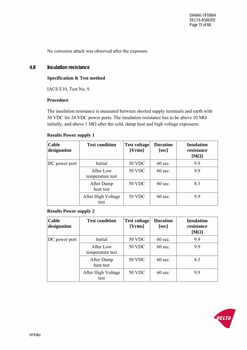
Procedure
The insulation resistance is measured between shorted supply terminals and earth with 50 VDC for 24 VDC power ports. The insulation resistance has to be above 10 MΩ initially, and above 1 MΩ after the cold, damp heat and high voltage exposures.
Results Power supply 1
Cable designation
Test condition
Test voltage[Vrms]
Duration [sec]
Insulation resistance
[MΩ] Initial 50 VDC 60 sec. 9.9
After Low temperature test
50 VDC 60 sec. 9.9
After Damp heat test
50 VDC 60 sec. 8.3
DC power port
After High Voltage test
50 VDC 60 sec. 9.9
Results Power supply 2
Cable designation
Test condition
Test voltage[Vrms]
Duration [sec]
Insulation resistance
[MΩ] Initial 50 VDC 60 sec. 9.9
After Low temperature test
50 VDC 60 sec. 9.9
After Damp heat test
50 VDC 60 sec. 8.5
DC power port
After High Voltage test
50 VDC 60 sec. 9.9
DANAK-1910664 DELTA-A506392 Page 16 of 68
HFR/lko
4.9 High voltage
Test method
IACS E10, Test No. 10.
Procedure
550 VAC, 50 Hz is applied between shorted supply terminals and earth for 1 minute for the 24 VDC supply line.
No flashover, breakdown etc. is acceptable.
Results
No flashover or breakdown was observed during the exposure. The insulation resistance was OK after the exposure, ref. Section 4.8.
4.10 Resonance search (4 g)
Specification
IACS E10, Test No. 7.
IEC 60945, clause 8.7.
Test method
IEC 60068-2-6:2007, Test Fc: Vibration (sinusoidal).
Severity and procedure
Frequency range : 2 - 100 Hz Frequency / amplitude : 2 - 25 Hz : ± 1.6 mm 25 - 100 Hz : ± 4 g Sweep rate : Max. 0.5 octave/min. Number of axes : 3 mutually perpendicular
The test object is de-energised during the exposure.
During the resonance search, the resonance frequencies are determined by means of stroboscopic light with slow motion facility and accelerometer measurements of the amplification factors (Q).
Resonance frequencies with an amplification factor above 2 are recorded.
DANAK-1910664 DELTA-A506392 Page 17 of 68
HFR/lko
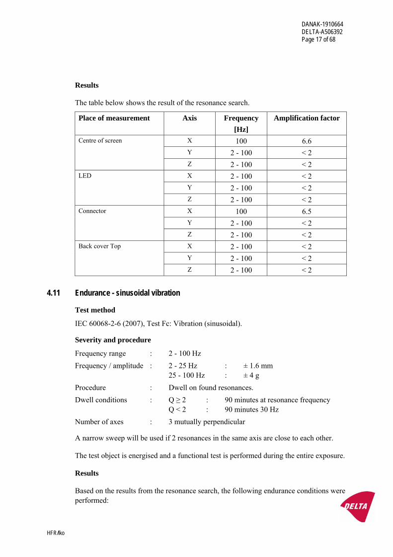
Results
The table below shows the result of the resonance search.
Place of measurement Axis Frequency [Hz]
Amplification factor
X 100 6.6 Y 2 - 100 < 2
Centre of screen
Z 2 - 100 < 2 X 2 - 100 < 2 Y 2 - 100 < 2
LED
Z 2 - 100 < 2 X 100 6.5 Y 2 - 100 < 2
Connector
Z 2 - 100 < 2 X 2 - 100 < 2 Y 2 - 100 < 2
Back cover Top
Z 2 - 100 < 2
4.11 Endurance - sinusoidal vibration
Test method
IEC 60068-2-6 (2007), Test Fc: Vibration (sinusoidal).
Severity and procedure
Frequency range : 2 - 100 Hz Frequency / amplitude : 2 - 25 Hz : ± 1.6 mm 25 - 100 Hz : ± 4 g Procedure : Dwell on found resonances. Dwell conditions : Q ≥ 2 : 90 minutes at resonance frequency Q < 2 : 90 minutes 30 Hz Number of axes : 3 mutually perpendicular
A narrow sweep will be used if 2 resonances in the same axis are close to each other.
The test object is energised and a functional test is performed during the entire exposure.
Results
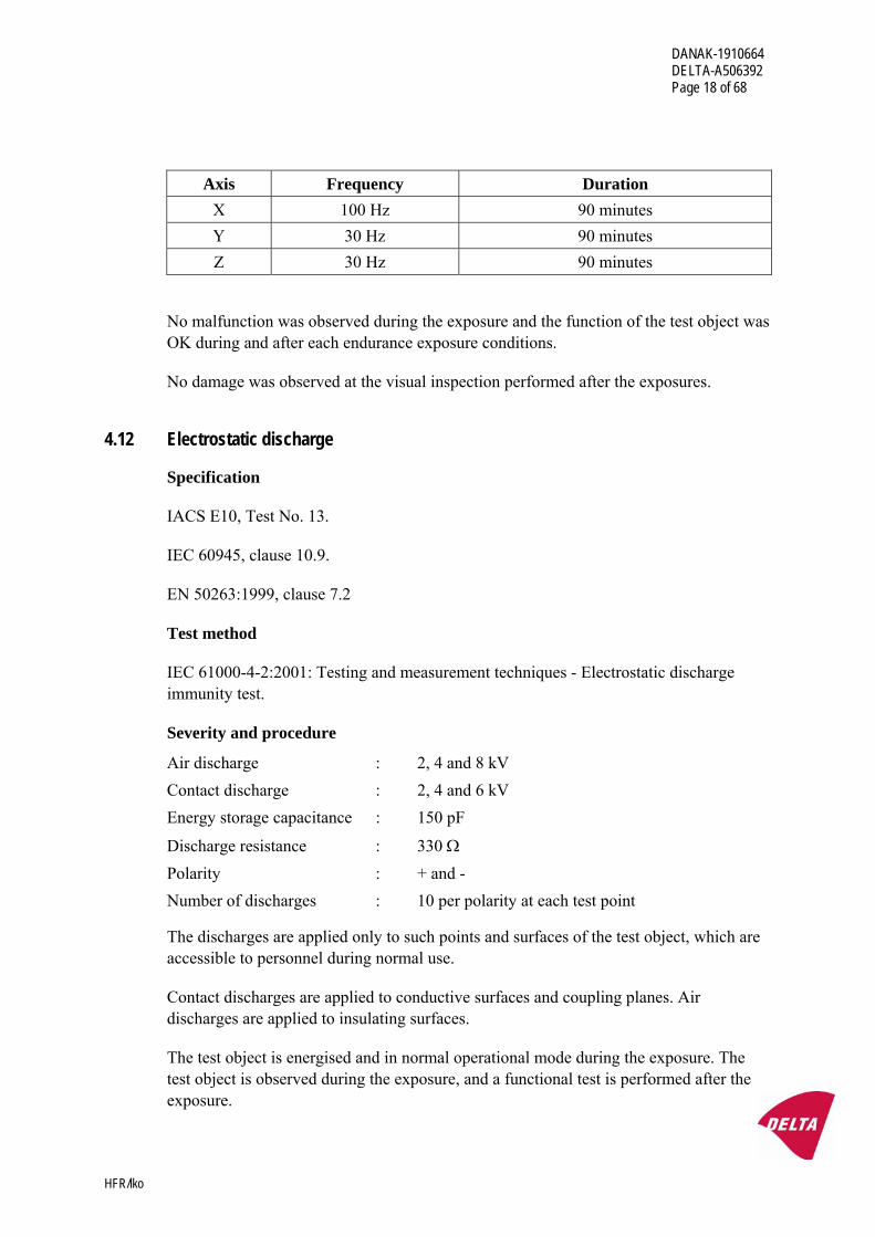
Based on the results from the resonance search, the following endurance conditions were performed:
DANAK-1910664 DELTA-A506392 Page 18 of 68
HFR/lko
Axis Frequency Duration X 100 Hz 90 minutes Y 30 Hz 90 minutes Z 30 Hz 90 minutes
No malfunction was observed during the exposure and the function of the test object was OK during and after each endurance exposure conditions.
No damage was observed at the visual inspection performed after the exposures.
4.12 Electrostatic discharge
Specification
IACS E10, Test No. 13.
IEC 60945, clause 10.9.
EN 50263:1999, clause 7.2
Test method
IEC 61000-4-2:2001: Testing and measurement techniques - Electrostatic discharge immunity test.
Severity and procedure
Air discharge : 2, 4 and 8 kV Contact discharge : 2, 4 and 6 kV Energy storage capacitance : 150 pF
Discharge resistance : 330 Ω Polarity : + and - Number of discharges : 10 per polarity at each test point
The discharges are applied only to such points and surfaces of the test object, which are accessible to personnel during normal use.
Contact discharges are applied to conductive surfaces and coupling planes. Air discharges are applied to insulating surfaces.
The test object is energised and in normal operational mode during the exposure. The test object is observed during the exposure, and a functional test is performed after the exposure.
DANAK-1910664 DELTA-A506392 Page 19 of 68
HFR/lko
Results
No malfunction was observed during the exposure and the function of the test object was OK after the exposure.
Performance criterion: B.
4.13 Radiated radio frequency interference
Specification
IACS E10, Test No. 14.
IEC 60945, clause 10.3.
EN 50263:1999, clause 7.2
Test method
IEC 61000-4-3:2006: Testing and measurement techniques - Radiated, radio-frequency, electromagnetic field immunity test.
Severity and procedure
IACS E10 and IEC 60945
Frequency range : 80 - 2000 MHz Field strength : 10 V/m Modulation : 80 %AM, 400 Hz sine wave
EN 50263
Frequency range : 895 - 905 MHz Field strength : 10 V/m Modulation : PM 200 Hz, 1000 Hz square wave
The test is performed in a semi anechoic room. The field is generated using linearly polarised broadband antennas.
The test object is energised and in normal operational mode during the exposure. The test object is observed during the exposure and a functional test is performed after the exposure.
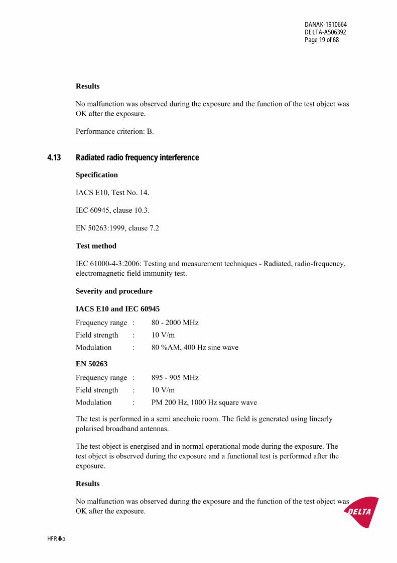
Results
No malfunction was observed during the exposure and the function of the test object was OK after the exposure.
DANAK-1910664 DELTA-A506392 Page 20 of 68
HFR/lko
Performance criterion: A.
4.14 Conducted low frequency interference
Specification
IACS E10:2006, Test No. 15.
Test method
IEC 61000-4-16 (1998-01): Test for immunity to conducted, common mode disturbances in the frequency range 0 Hz to 150 kHz.
Severity and procedure
Frequency range : 0.05 - 10 kHz Amplitude (DC-supplied) : 0.05 - 10 kHz : 10 % of Unom./ min. 3 Vrms Maximum applied power : 2.0 W
The impedance of the test generator is less than 1 Ω.
The test signal is superimposed on the power supply lines via a coupling transformer.
The test object is energised and in normal operational mode during the exposure. The test object is observed during the exposure, and a functional test is performed after the exposure.
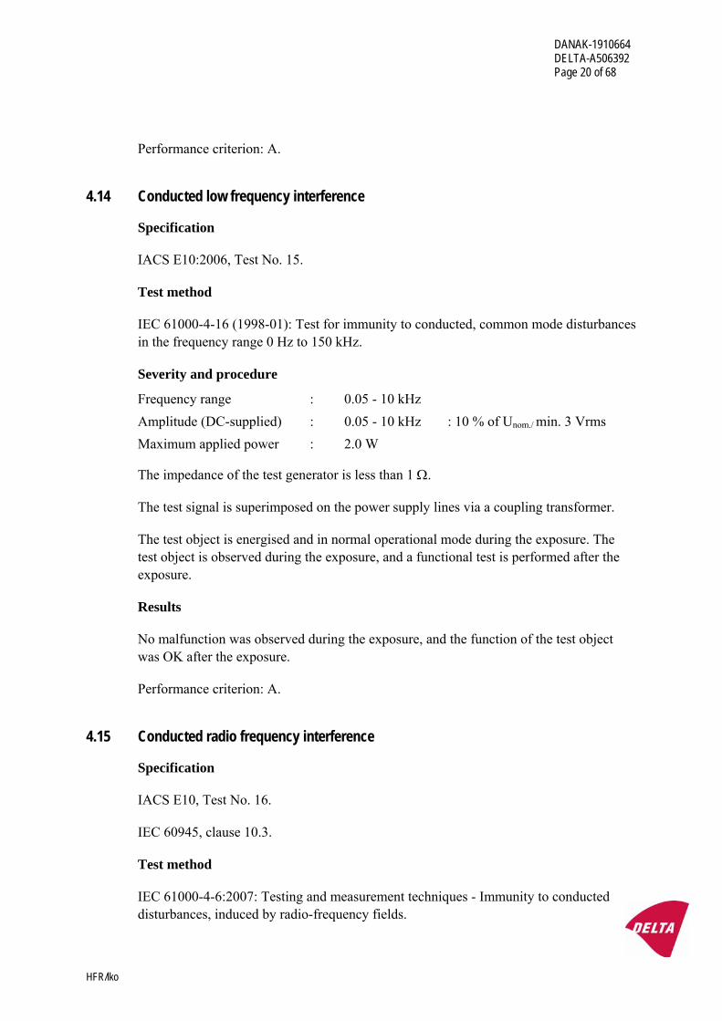
Results
No malfunction was observed during the exposure, and the function of the test object was OK after the exposure.
Performance criterion: A.
4.15 Conducted radio frequency interference
Specification
IACS E10, Test No. 16.
IEC 60945, clause 10.3.
Test method
IEC 61000-4-6:2007: Testing and measurement techniques - Immunity to conducted disturbances, induced by radio-frequency fields.
DANAK-1910664 DELTA-A506392 Page 21 of 68
HFR/lko
Severity and procedure
Frequency range : 150 kHz - 80 MHz Amplitude : 0.15 - 80 MHz : 10 Vrms Modulation : 80 %AM, 400 Hz sine wave
The test object is supplied with power via a coupling / decoupling network.
The test signal is coupled to the power lines and signal lines via coupling networks. The coupling impedance is 150 Ω.
The test object is energised and in normal operational mode during the exposure. The test object is observed during the exposure, and a functional test is performed after the exposure.
Results
No malfunction was observed during the exposure, and the function of the test object was OK after the exposure.
Performance criterion: A.
4.16 Fast transients (burst)
Specification
IACS E10, Test No. 17.
IEC 60945, clause 10.5.
EN 50263:1999, clause 7.2
Test method
IEC 61000-4-4:2004: Testing and measurement techniques - Section 4: Electrical fast transient / burst immunity test.
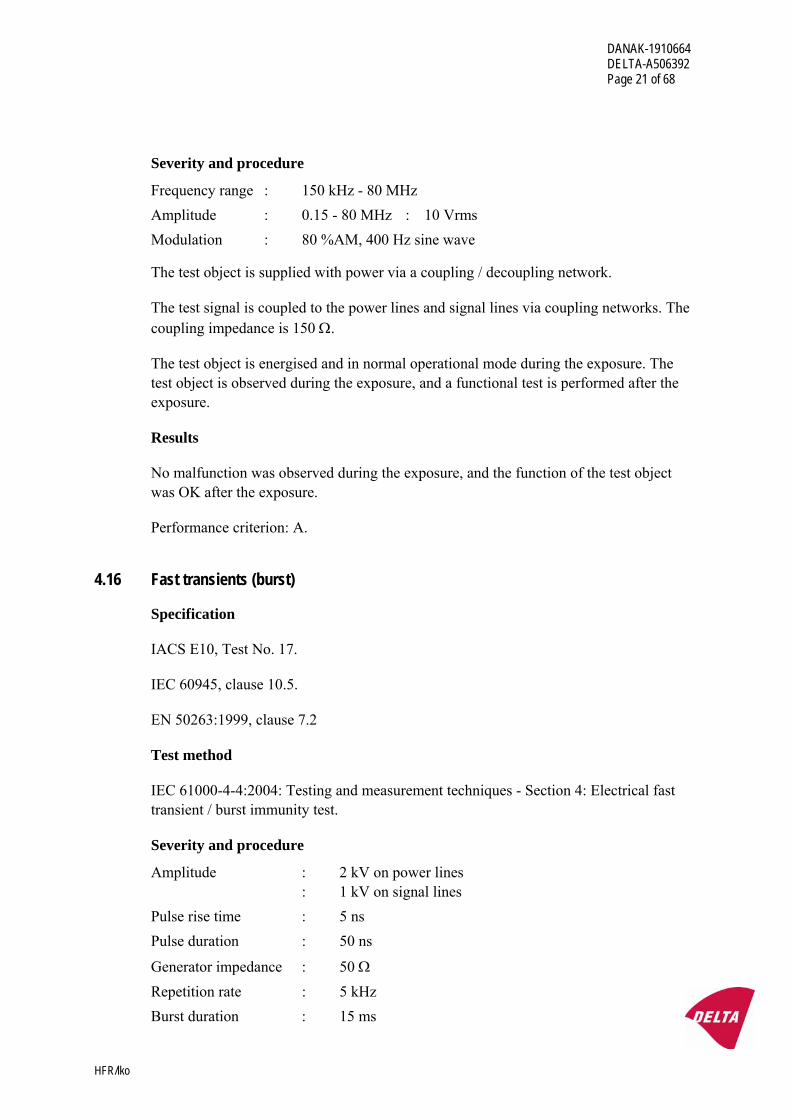
Severity and procedure
Amplitude : 2 kV on power lines : 1 kV on signal lines Pulse rise time : 5 ns Pulse duration : 50 ns
Generator impedance : 50 Ω Repetition rate : 5 kHz Burst duration : 15 ms
DANAK-1910664 DELTA-A506392 Page 22 of 68
HFR/lko
Burst period time : 300 ms
The test object is supplied with power via a transient coupling network. The test signal is successively coupled to each power line and protective earth with reference to the ground plane.
The test signal is injected on the signal lines using a capacitive coupling clamp. The clamp is successively used on selected signal cables.
The test signal is injected on the power lines for 5 minutes, using each coupling mode and each polarity, and then on the signal lines for 5 minutes using each polarity.
The test object is energised and in normal operational mode during the exposure. The test object is observed during the exposure and a functional test is performed after the exposure.
Results
No malfunction was observed during the exposure and the function of the test object was OK after the exposure.
Performance criterion: B.
4.17 Burst 1 MHz
Specification & Test method
EN 50263:1999, clause 7.2.
Severity and procedure
Amplitude : 1 kV differential mode on power lines : 2.5 kV common mode on power lines : 1 kV common mode on signal lines Pulse rise time : 75 ns
Generator impedance : 200 Ω Repetition rate : 400 Hz
The test object is supplied with power via a transient coupling network. The test signal is successively coupled to each power line and protective earth with reference to the ground plane.
The test signal is injected on the signal lines using a capacitive coupling clamp. The clamp is successively used on selected signal cables.
The test signal is injected on the power lines for 5 minutes, using each coupling mode and each polarity, and then on the signal lines for 5 minutes using each polarity.
DANAK-1910664 DELTA-A506392 Page 23 of 68
HFR/lko
The test object is energised and in normal operational mode during the exposure. The test object is observed during the exposure and a functional test is performed after the exposure.
Results
No malfunction was observed during the exposure and the function of the test object was OK after the exposure.
Performance criterion: B.
4.18 Slow transients (surge)
Specification
IACS E10, Test No. 18.
IEC 60945, clause 10.6.
EN 50263:1999, clause 7.2.
Test method
IEC 61000-4-5:2005: Testing and measurement techniques - Surge immunity test.
Severity and procedure
IECS E10 & IEC 60945 Amplitude power ports : 1 kV line-to-earth, 0.5 kV line-to-line EN 50263 Amplitude power ports : 1 kV Differential mode : 2 kV Common mode Voltage rise time : 1.2 µs (open circuit) Voltage decay time : 50 µs (open circuit)
The impedance of the test generator is 2 Ω for line-to-line coupling and 12 Ω for line-to-earth coupling.
The test object is energised and in normal operational mode during the exposure. The test object is observed during the exposure, and a functional test is performed after the exposure.
DANAK-1910664 DELTA-A506392 Page 24 of 68
HFR/lko
Results
No malfunction was observed during the exposure and the function of the test object was OK after the exposure.
Performance criterion: B.
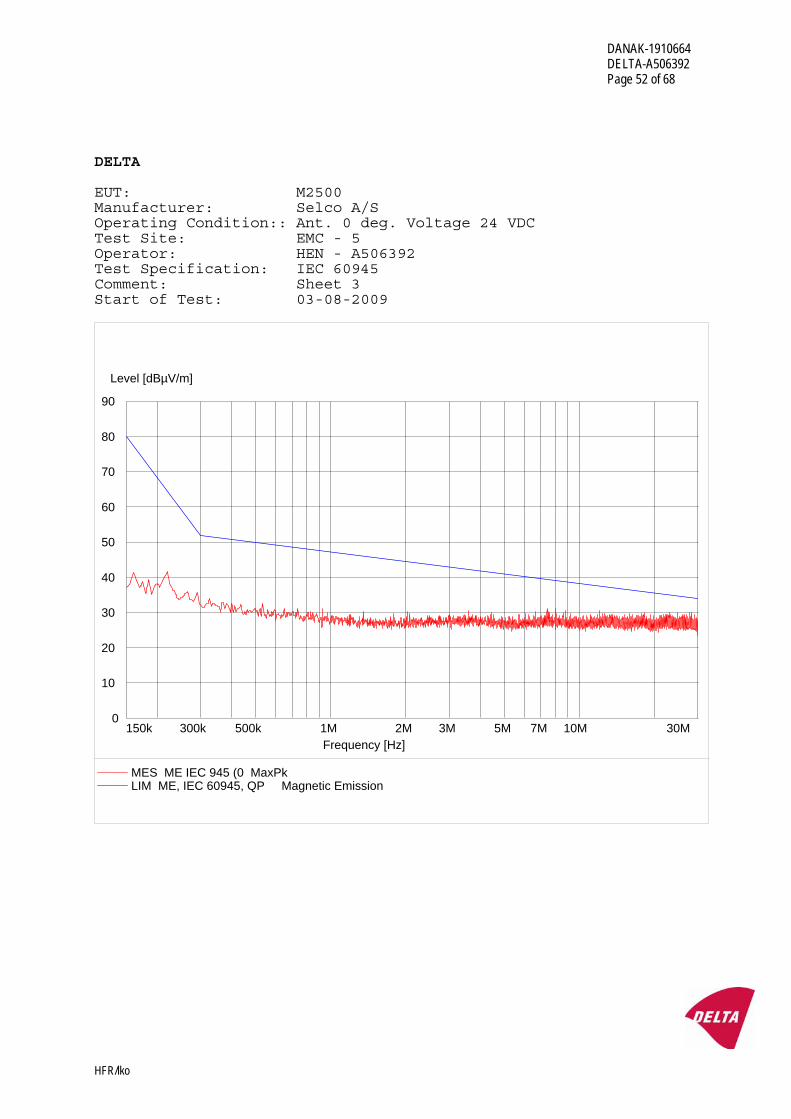
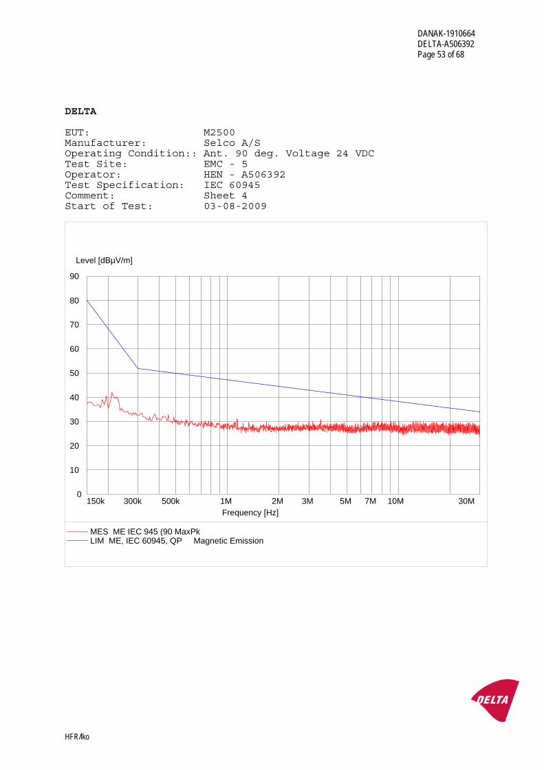
4.19 Radiated emissions
Specification
IACS E10:2006, Section 19.
EN 50263:1999, clause 7.1.
Test methods
CISPR 16-2-3:2006: Specification for radio disturbance and immunity measuring apparatus and methods - Part 2-3: Methods of measurement of disturbance and immunity - Radiated disturbance measurements.
Severity and procedure
IACS E10
General Power Distribution Zone Frequency range : 0.15 - 2000 MHz
Limits (quasi-peak) : 0.15 - 30 MHz : 80 - 50 dBμV/m 30 - 100 MHz : 60 - 54 dBμV/m 100 - 2000 MHz : 54 dBμV/m, except for 156 - 165 MHz : 24 dBμV/m
EN 50263
Frequency range : 30 - 1000 MHz
Limits (quasi-peak) : 30 - 230 MHz : 50 dBμV/m 230 - 1000 MHz : 57 dBμV/m The electric field is measured with antennas at a distance of 3 m.
The measuring bandwidth is 200 Hz in the frequency range 10 kHz - 150 kHz, 9 kHz in the frequency range 150 kHz - 30 MHz and 120 kHz in the frequency range 30 MHz - 2000 MHz, except for the frequency range 156 MHz - 165 MHz where the measuring bandwidth is 9 kHz.
The test object is energised and in normal operational mode during the measurement.
DANAK-1910664 DELTA-A506392 Page 25 of 68
HFR/lko
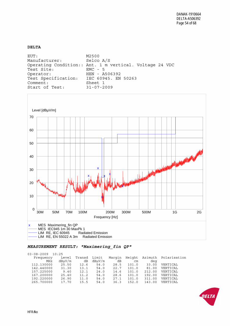
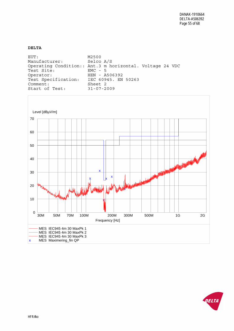
Results
The radiated emissions were within the specified limits. Test record sheets of the radiated emission measurements are enclosed in Annex 4.
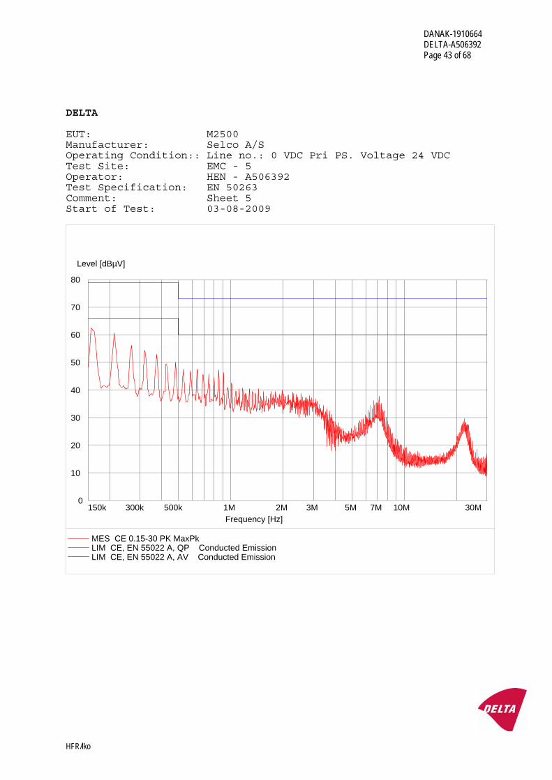
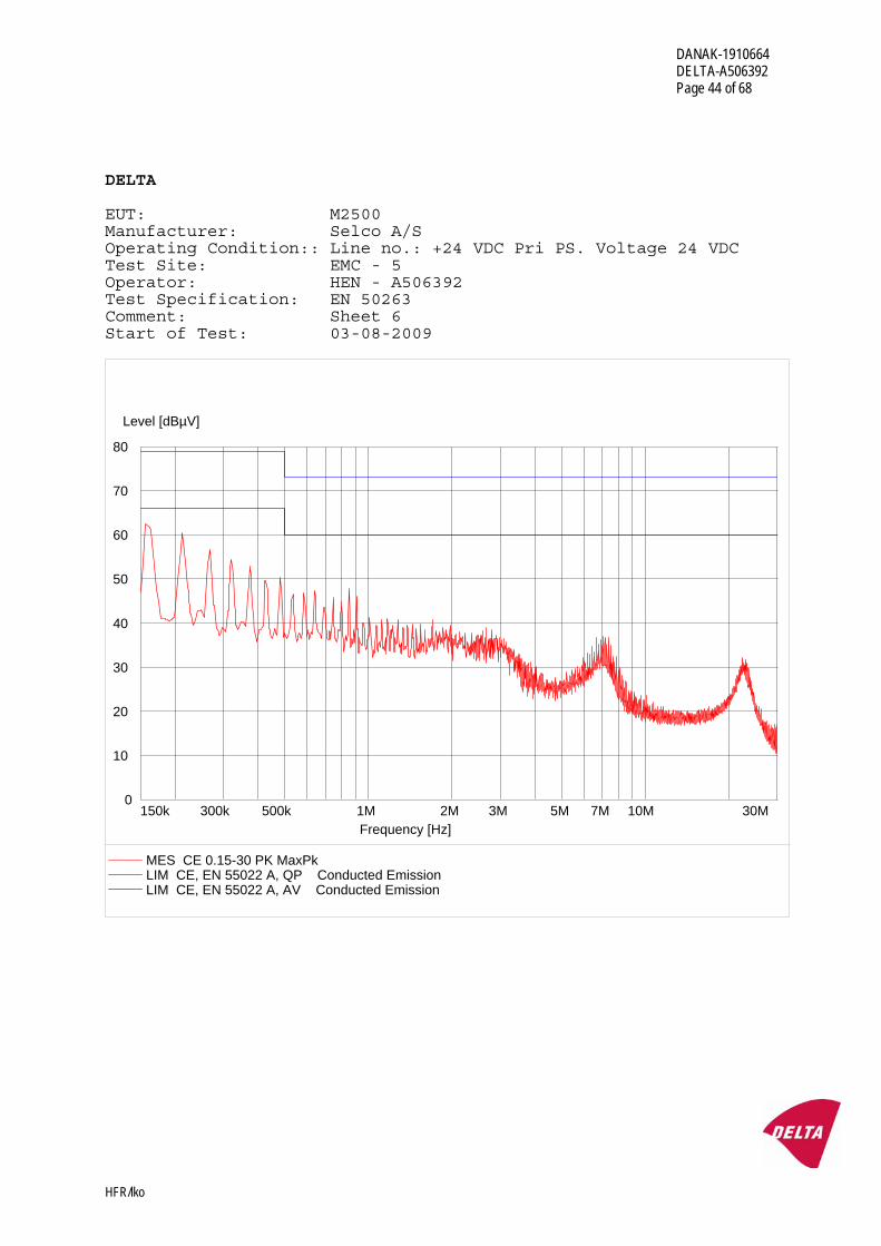
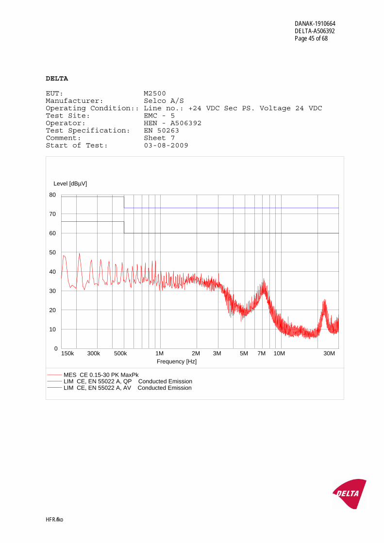
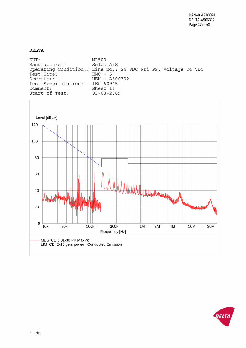
4.20 Conducted emissions
Specification
IACS E10:2006, Section 20.
EN 50263:1999, clause 7.1.
Test methods
CISPR16-2-1:2008: Specification for radio disturbance and immunity measuring apparatus and methods - Part 2-1: Methods of measurement of disturbances and immunity - Conducted disturbance measurements
Severity and procedure
IACS E10
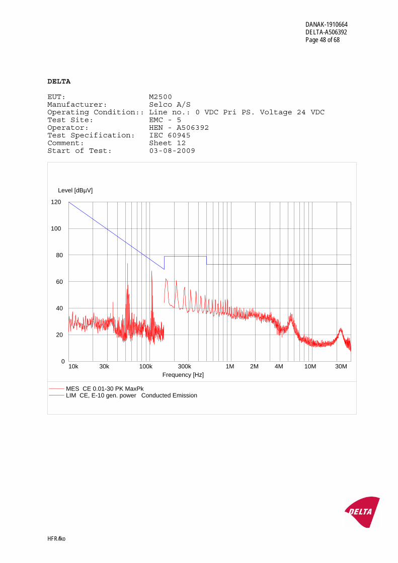
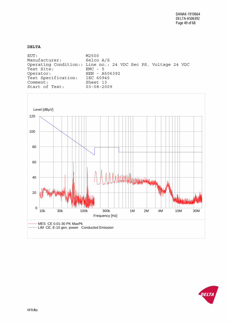
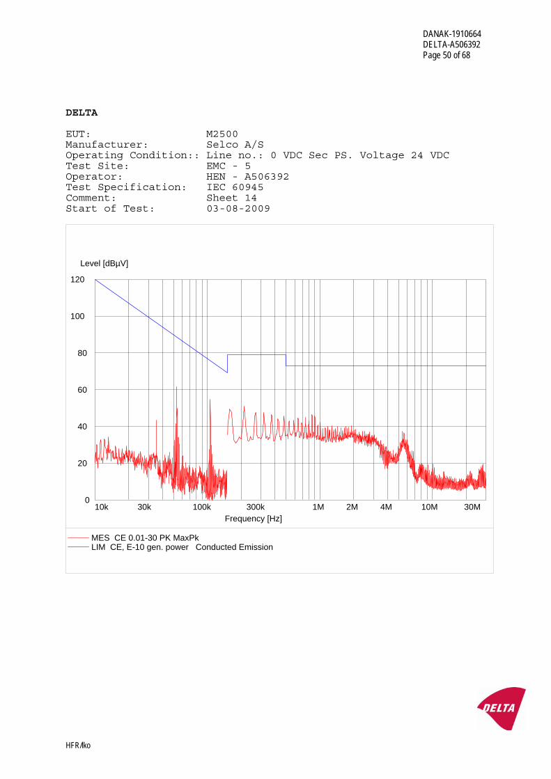
General Power Distribution Zone Frequency range : 0.01 - 30 MHz
Limits (quasi-peak) : 0.01 - 0.15 MHz : 120 - 69 dBμV 0.15 - 0.50 MHz : 79 dBμV 0.50 - 30 MHz : 73 dBμV
EN 50263
Frequency range : 0.15 - 30 MHz
Limits (quasi-peak) : 0.15 - 0.5 MHz : 79 dBμV 0.5 - 30 MHz : 73 dBμV
Limits (average) : 0.15 - 0.5 MHz : 66 dBμV 0.5 - 30 MHz : 60 dBμV
The radio frequency voltage is measured at the power supply terminals of the test object by a receiver through an artificial mains network.
The measuring bandwidth is 200 Hz in the frequency range 10 kHz - 150 kHz and 9 kHz in the frequency range 150 kHz - 30 MHz.
The test object is energised and in normal operational mode during the measurement.
DANAK-1910664 DELTA-A506392 Page 26 of 68
HFR/lko
Results
The conducted emissions were within the specified limits. Test record sheets of the conducted emission measurements are enclosed in Annex 3.
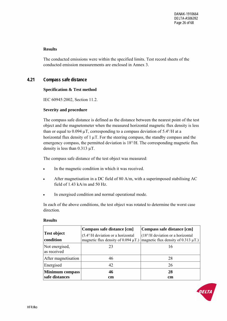
4.21 Compass safe distance
Specification & Test method
IEC 60945:2002, Section 11.2.
Severity and procedure
The compass safe distance is defined as the distance between the nearest point of the test object and the magnetometer when the measured horizontal magnetic flux density is less than or equal to 0.094 μT, corresponding to a compass deviation of 5.4°/H at a horizontal flux density of 1 μT. For the steering compass, the standby compass and the emergency compass, the permitted deviation is 18°/H. The corresponding magnetic flux density is less than 0.313 µT.
The compass safe distance of the test object was measured:
• In the magnetic condition in which it was received.
• After magnetisation in a DC field of 80 A/m, with a superimposed stabilising AC field of 1.43 kA/m and 50 Hz.
• In energised condition and normal operational mode.
In each of the above conditions, the test object was rotated to determine the worst case direction.
Results
Test object condition
Compass safe distance [cm] (5.4°/H deviation or a horizontal magnetic flux density of 0.094 µT.)
Compass safe distance [cm] (18°/H deviation or a horizontal magnetic flux density of 0.313 µT.)
Not energised, as received
23 16
After magnetisation 46 28 Energised 42 26 Minimum compass safe distances
46 cm
28 cm
DANAK-1910664 DELTA-A506392 Page 27 of 68
HFR/lko
4.22 Enclosure protection, IP 2X
Specification
IEC 60945, clause 12.1.
Test method
IEC 60529:2001: Degrees of protection provided by enclosures (IP Code).
Severity and procedure
The test object is subjected to a test corresponding to IEC 60529:2001, table 1, first characteristic numeral 2 (IP 2X): “Protection against access to hazardous parts with a finger”, and thus IEC 60945:2001, clause 12.1: “Protection against access to dangerous voltages”.
Results
The test object has adequate protection against access to hazardous parts with a finger, i.e. no openings greater than 12 mm Ø were measured.
4.23 Rated power frequency magnetic field
Test method
IEC 61000-4-8:2001: Testing and measurement techniques - Power frequency magnetic field immunity test.
Severity and procedure
Magnetic field strength : 30 A/m Test frequency : 50, 60 Hz
The test is performed in three orthogonal orientations.
The test object is energised and in normal operational mode during the exposure. The test object is observed during the exposure, and a functional test is performed after the exposure.
Results
No malfunction was observed during the exposure and the function of the test object was OK after the exposure.
Performance criterion: A.
DANAK-1910664 DELTA-A506392 Page 28 of 68
HFR/lko
Annex 1
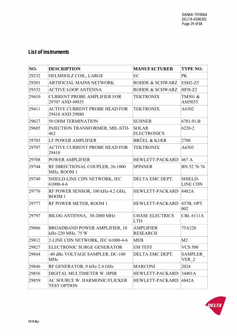
List of instruments
DANAK-1910664 DELTA-A506392 Page 29 of 68
HFR/lko
List of instruments NO. DESCRIPTION MANUFACTURER TYPE NO. 29232 HELMHOLZ COIL, LARGE EC PK 29301 ARTIFICIAL MAINS NETWORK ROHDE & SCHWARZ ESH2-Z5 29332 ACTIVE LOOP ANTENNA ROHDE & SCHWARZ HFH-Z2 29410 CURRENT PROBE AMPLIFIER FOR
29707 AND 49035 TEKTRONIX TM501 &
AM503T 29411 ACTIVE CURRENT PROBE HEAD FOR
29410 AND 29880 TEKTRONIX A6302
29627 50 OHM TERMINATION SUHNER 6701.01.B 29685 INJECTION TRANSFORMER, MIL-STD-
462 SOLAR ELECTRONICS
6220-2
29703 LF POWER AMPLIFIER BRÜEL & KJÆR 2708 29707 ACTIVE CURRENT PROBE HEAD FOR
29410 TEKTRONIX A6303
29708 POWER AMPLIFIER HEWLETT-PACKARD 467 A 29744 RF DIRECTIONAL COUPLER, 26-1000
MHz, ROOM 1 SPINNER BN 52 76 76
29749 SHIELD-LINE CDN NETWORK, IEC 61000-4-6
DELTA EMC DEPT. SHIELD-LINE CDN
29776 RF POWER SENSOR, 100 kHz-4.2 GHz, ROOM 1
HEWLETT-PACKARD 8482A
29777 RF POWER METER, ROOM 1 HEWLETT-PACKARD 437B, OPT. 002
29797 BILOG ANTENNA, 30-2000 MHz CHASE ELECTRICS LTD
CBL 6111A
29806 BROADBAND POWER AMPLIFIER, 10 kHz-220 MHz, 75 W
AMPLIFIER RESEARCH
75A220
29812 2-LINE CDN NETWORK, IEC 61000-4-6 MEB M2 29827 ELECTRONIC SURGE GENERATOR EM TEST VCS 500 29844 -40 dBc VOLTAGE SAMPLER, DC-100
MHz DELTA EMC DEPT. SAMPLER_
VER_2 29846 RF GENERATOR, 9 kHz-2.4 GHz MARCONI 2024 29856 DIGITAL MULTIMETER W. HPIB HEWLETT-PACKARD 34401A 29859 AC SOURCE W. HARMONIC/FLICKER
TEST OPTION HEWLETT-PACKARD 6842A
DANAK-1910664 DELTA-A506392 Page 30 of 68
HFR/lko
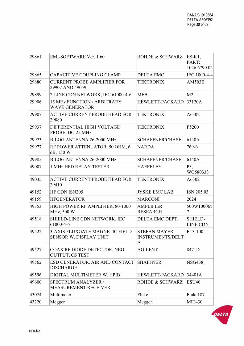
29861 EMI-SOFTWARE Ver. 1.60 ROHDE & SCHWARZ ES-K1,
PART: 1026.6790.02
29865 CAPACITIVE COUPLING CLAMP DELTA EMC IEC 1000-4-429880 CURRENT PROBE AMPLIFIER FOR
29907 AND 49059 TEKTRONIX AM503B
29899 2-LINE CDN NETWORK, IEC 61000-4-6 MEB M2 29906 15 MHz FUNCTION / ARBITRARY
WAVE GENERATOR HEWLETT-PACKARD 33120A
29907 ACTIVE CURRENT PROBE HEAD FOR 29880
TEKTRONIX A6302
29937 DIFFERENTIAL HIGH VOLTAGE PROBE, DC-25 MHz
TEKTRONIX P5200
29973 BILOG ANTENNA 26-2000 MHz SCHAFFNER/CHASE 6140A 29977 RF POWER ATTENUATOR, 50 OHM, 6
dB, 150 W NARDA 769-6
29985 BILOG ANTENNA 26-2000 MHz SCHAFFNER/CHASE 6140A 49007 1 MHz HFD RELAY TESTER HAEFELEY P3,
WO580333 49035 ACTIVE CURRENT PROBE HEAD FOR
29410 TEKTRONIX A6302
49152 HF CDN ISN205 JYSKE EMC LAB ISN 205.03 49159 HFGENERATOR MARCONI 2024 49353 HIGH POWER RF AMPLIFIER, 80-1000
MHz, 500 W AMPLIFIER RESEARCH
500W1000M7
49518 SHIELD-LINE CDN NETWORK, IEC 61000-4-6
DELTA EMC DEPT. SHIELD-LINE CDN
49522 3-AXIS FLUXGATE MAGNETIC FIELD SENSOR W. DISPLAY UNIT
STEFAN MAYER INSTRUMENTS/DELTA
FL3-100
49527 COAX RF DIODE DETECTOR, NEG. OUTPUT, CS TEST
AGILENT 8471D
49562 ESD GENERATOR, AIR AND CONTACT DISCHARGE
SHAFFNER NSG438
49596 DIGITAL MULTIMETER W. HPIB HEWLETT-PACKARD 34401A 49600 SPECTRUM ANALYZER /
MEASUREMENT RECEIVER ROHDE & SCHWARZ ESU40
43074 Multimeter Fluke Fluke187 43220 Megger Megger MIT430
DANAK-1910664 DELTA-A506392 Page 31 of 68
HFR/lko
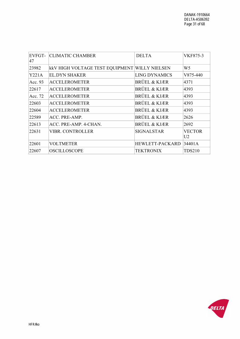
EVFGT-47
CLIMATIC CHAMBER DELTA VKF875-3
23982 kkV HIGH VOLTAGE TEST EQUIPMENT WILLY NIELSEN W5 Y221A EL.DYN SHAKER LING DYNAMICS V875-440 Acc. 93 ACCELEROMETER BRÜEL & KJÆR 4371 22617 ACCELEROMETER BRÜEL & KJÆR 4393 Acc. 72 ACCELEROMETER BRÜEL & KJÆR 4393 22603 ACCELEROMETER BRÜEL & KJÆR 4393 22604 ACCELEROMETER BRÜEL & KJÆR 4393 22589 ACC. PRE-AMP. BRÜEL & KJÆR 2626 22613 ACC. PRE-AMP. 4-CHAN. BRÜEL & KJÆR 2692 22631 VIBR. CONTROLLER SIGNALSTAR VECTOR
U2 22601 VOLTMETER HEWLETT-PACKARD 34401A 22607 OSCILLOSCOPE TEKTRONIX TDS210
DANAK-1910664 DELTA-A506392 Page 32 of 68
HFR/lko
Annex 2
Photos
DANAK-1910664 DELTA-A506392 Page 33 of 68
HFR/lko
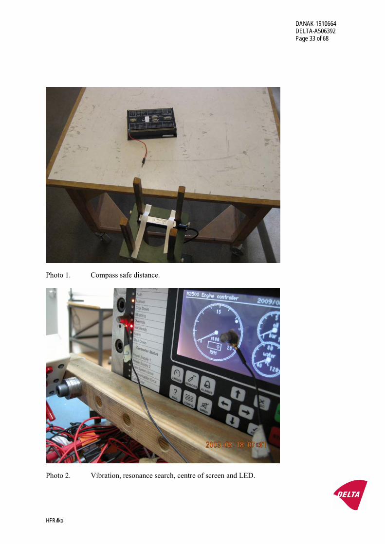
Photo 1. Compass safe distance.
Photo 2. Vibration, resonance search, centre of screen and LED.
DANAK-1910664 DELTA-A506392 Page 34 of 68
HFR/lko
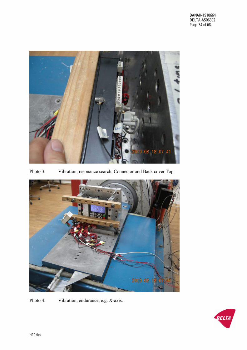
Photo 3. Vibration, resonance search, Connector and Back cover Top.
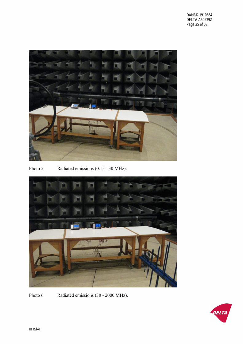
Photo 4. Vibration, endurance, e.g. X-axis.
DANAK-1910664 DELTA-A506392 Page 35 of 68
HFR/lko
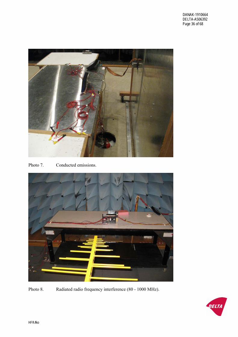
Photo 5. Radiated emissions (0.15 - 30 MHz).
Photo 6. Radiated emissions (30 - 2000 MHz).
DANAK-1910664 DELTA-A506392 Page 36 of 68
HFR/lko
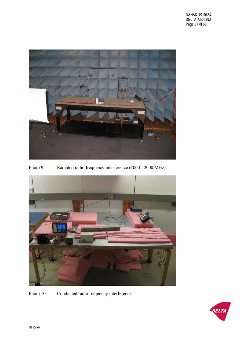
Photo 7. Conducted emissions.
Photo 8. Radiated radio frequency interference (80 - 1000 MHz).
DANAK-1910664 DELTA-A506392 Page 37 of 68
HFR/lko
Photo 9. Radiated radio frequency interference (1000 - 2000 MHz).
Photo 10. Conducted radio frequency interference.
DANAK-1910664 DELTA-A506392 Page 38 of 68
HFR/lko
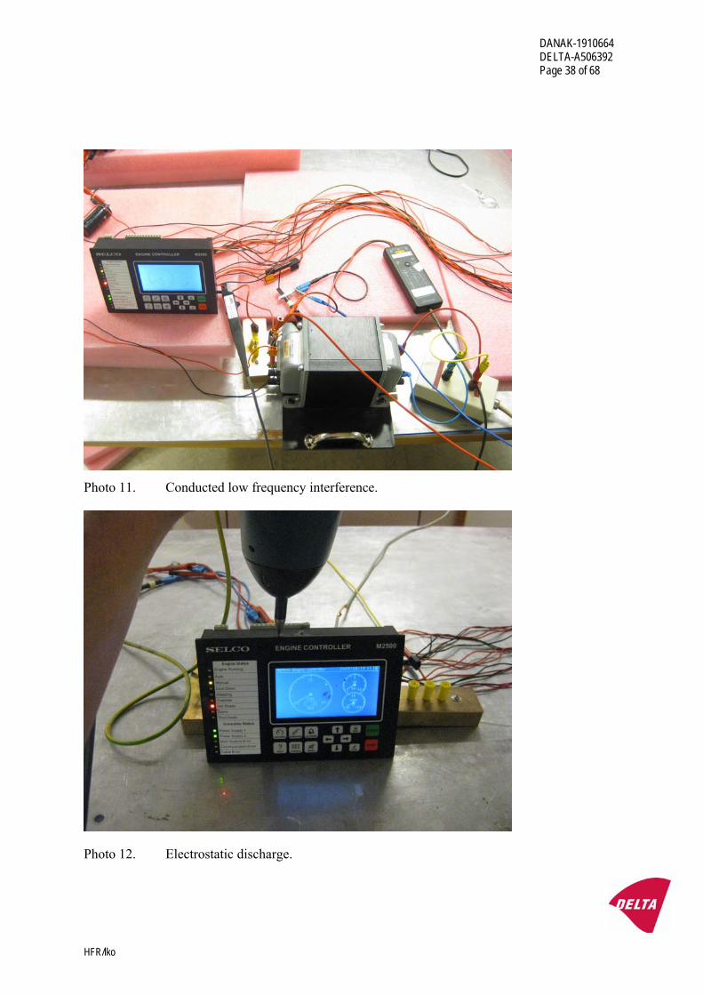
Photo 11. Conducted low frequency interference.
Photo 12. Electrostatic discharge.
DANAK-1910664 DELTA-A506392 Page 39 of 68
HFR/lko
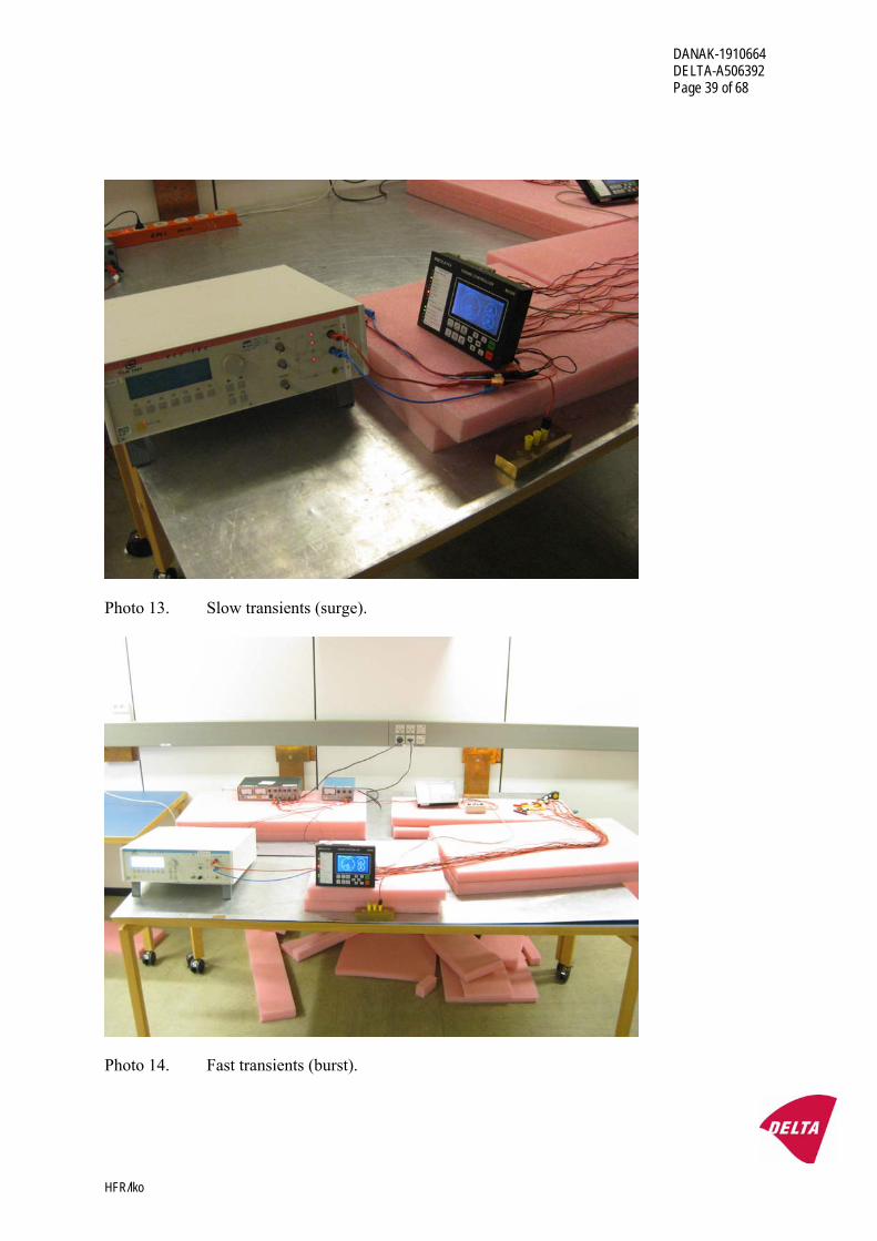
Photo 13. Slow transients (surge).
Photo 14. Fast transients (burst).
DANAK-1910664 DELTA-A506392 Page 40 of 68
HFR/lko
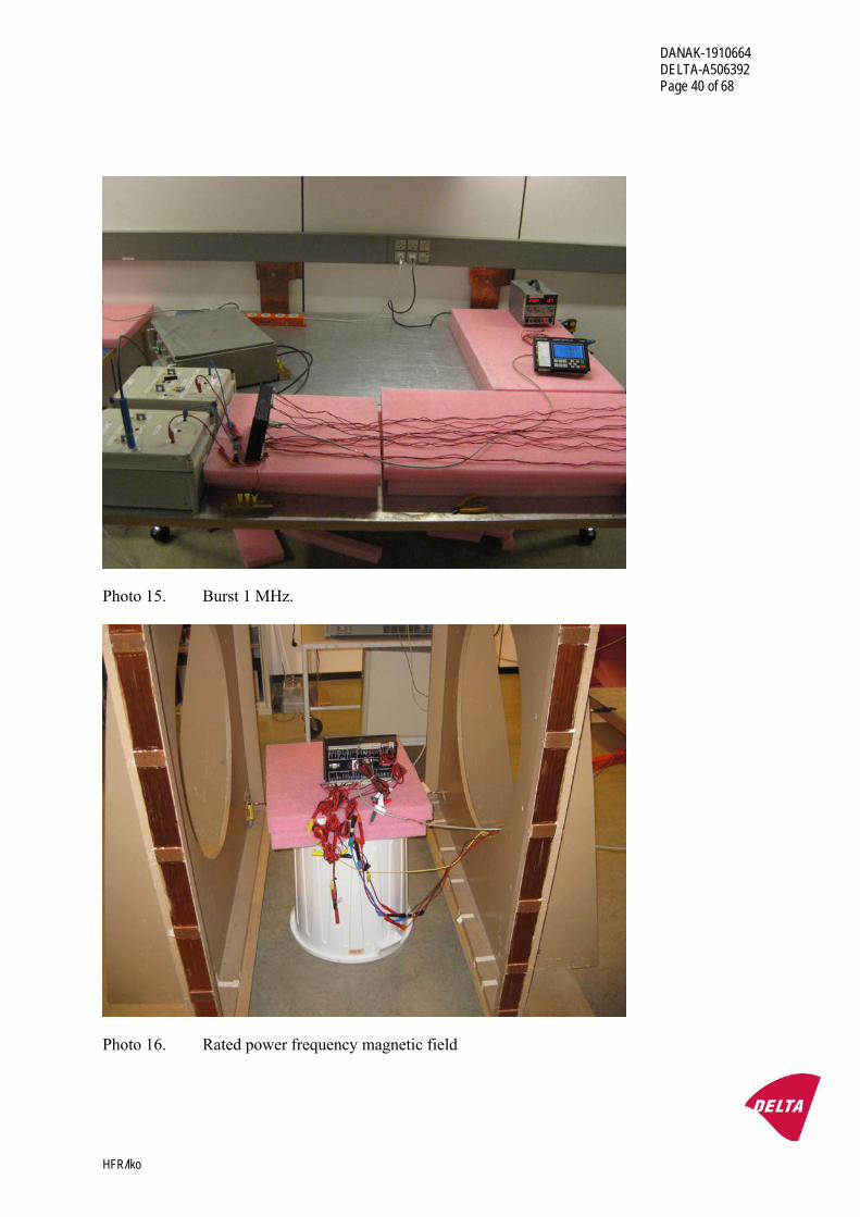
Photo 15. Burst 1 MHz.
Photo 16. Rated power frequency magnetic field
DANAK-1910664 DELTA-A506392 Page 41 of 68
HFR/lko
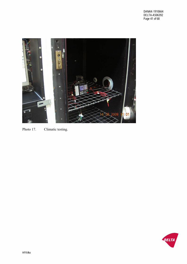
Photo 17. Climatic testing.

DANAK-1910664 DELTA-A506392 Page 42 of 68
HFR/lko
Annex 3
Test record sheets - Conducted emissions
DANAK-1910664 DELTA-A506392 Page 43 of 68
HFR/lko
DELTA EUT: M2500 Manufacturer: Selco A/S Operating Condition:: Line no.: 0 VDC Pri PS. Voltage 24 VDC Test Site: EMC - 5 Operator: HEN - A506392 Test Specification: EN 50263 Comment: Sheet 5 Start of Test: 03-08-2009
0
10
20
30
40
50
60
70
80
Level [dBµV]
150k 300k 500k 1M 2M 3M 5M 7M 10M 30MFrequency [Hz]
MES CE 0.15-30 PK MaxPk LIM CE, EN 55022 A, QP Conducted EmissionLIM CE, EN 55022 A, AV Conducted Emission
DANAK-1910664 DELTA-A506392 Page 44 of 68
HFR/lko
DELTA EUT: M2500 Manufacturer: Selco A/S Operating Condition:: Line no.: +24 VDC Pri PS. Voltage 24 VDC Test Site: EMC - 5 Operator: HEN - A506392 Test Specification: EN 50263 Comment: Sheet 6 Start of Test: 03-08-2009
0
10
20
30
40
50
60
70
80
Level [dBµV]
150k 300k 500k 1M 2M 3M 5M 7M 10M 30MFrequency [Hz]
MES CE 0.15-30 PK MaxPk LIM CE, EN 55022 A, QP Conducted EmissionLIM CE, EN 55022 A, AV Conducted Emission
DANAK-1910664 DELTA-A506392 Page 45 of 68
HFR/lko
DELTA EUT: M2500 Manufacturer: Selco A/S Operating Condition:: Line no.: +24 VDC Sec PS. Voltage 24 VDC Test Site: EMC - 5 Operator: HEN - A506392 Test Specification: EN 50263 Comment: Sheet 7 Start of Test: 03-08-2009
0
10
20
30
40
50
60
70
80
Level [dBµV]
150k 300k 500k 1M 2M 3M 5M 7M 10M 30MFrequency [Hz]
MES CE 0.15-30 PK MaxPk LIM CE, EN 55022 A, QP Conducted EmissionLIM CE, EN 55022 A, AV Conducted Emission

DANAK-1910664 DELTA-A506392 Page 46 of 68
HFR/lko
DELTA EUT: M2500 Manufacturer: Selco A/S Operating Condition:: Line no.: 0 VDC Sec PS. Voltage 24 VDC Test Site: EMC - 5 Operator: HEN - A506392 Test Specification: EN 50263 Comment: Sheet 8 Start of Test: 03-08-2009
0
10
20
30
40
50
60
70
80
Level [dBµV]
150k 300k 500k 1M 2M 3M 5M 7M 10M 30MFrequency [Hz]
MES CE 0.15-30 PK MaxPk LIM CE, EN 55022 A, QP Conducted EmissionLIM CE, EN 55022 A, AV Conducted Emission
DANAK-1910664 DELTA-A506392 Page 47 of 68
HFR/lko
DELTA EUT: M2500 Manufacturer: Selco A/S Operating Condition:: Line no.: 24 VDC Pri PS. Voltage 24 VDC Test Site: EMC - 5 Operator: HEN - A506392 Test Specification: IEC 60945 Comment: Sheet 11 Start of Test: 03-08-2009
0
20
40
60
80
100
120
Level [dBµV]
10k 30k 100k 300k 1M 2M 4M 10M 30MFrequency [Hz]
MES CE 0.01-30 PK MaxPk LIM CE, E-10 gen. power Conducted Emission
DANAK-1910664 DELTA-A506392 Page 48 of 68
HFR/lko
DELTA EUT: M2500 Manufacturer: Selco A/S Operating Condition:: Line no.: 0 VDC Pri PS. Voltage 24 VDC Test Site: EMC - 5 Operator: HEN - A506392 Test Specification: IEC 60945 Comment: Sheet 12 Start of Test: 03-08-2009
0
20
40
60
80
100
120
Level [dBµV]
10k 30k 100k 300k 1M 2M 4M 10M 30MFrequency [Hz]
MES CE 0.01-30 PK MaxPk LIM CE, E-10 gen. power Conducted Emission
DANAK-1910664 DELTA-A506392 Page 49 of 68
HFR/lko
DELTA EUT: M2500 Manufacturer: Selco A/S Operating Condition:: Line no.: 24 VDC Sec PS. Voltage 24 VDC Test Site: EMC - 5 Operator: HEN - A506392 Test Specification: IEC 60945 Comment: Sheet 13 Start of Test: 03-08-2009
0
20
40
60
80
100
120
Level [dBµV]
10k 30k 100k 300k 1M 2M 4M 10M 30MFrequency [Hz]
MES CE 0.01-30 PK MaxPk LIM CE, E-10 gen. power Conducted Emission
DANAK-1910664 DELTA-A506392 Page 50 of 68
HFR/lko
DELTA EUT: M2500 Manufacturer: Selco A/S Operating Condition:: Line no.: 0 VDC Sec PS. Voltage 24 VDC Test Site: EMC - 5 Operator: HEN - A506392 Test Specification: IEC 60945 Comment: Sheet 14 Start of Test: 03-08-2009
0
20
40
60
80
100
120
Level [dBµV]
10k 30k 100k 300k 1M 2M 4M 10M 30MFrequency [Hz]
MES CE 0.01-30 PK MaxPk LIM CE, E-10 gen. power Conducted Emission
DANAK-1910664 DELTA-A506392 Page 51 of 68
HFR/lko
Annex 4
Test record sheets - Radiated emissions
DANAK-1910664 DELTA-A506392 Page 52 of 68
HFR/lko
DELTA EUT: M2500 Manufacturer: Selco A/S Operating Condition:: Ant. 0 deg. Voltage 24 VDC Test Site: EMC - 5 Operator: HEN - A506392 Test Specification: IEC 60945 Comment: Sheet 3 Start of Test: 03-08-2009
0
10
20
30
40
50
60
70
80
90
Level [dBµV/m]
150k 300k 500k 1M 2M 3M 5M 7M 10M 30MFrequency [Hz]
MES ME IEC 945 (0 MaxPk LIM ME, IEC 60945, QP Magnetic Emission
DANAK-1910664 DELTA-A506392 Page 53 of 68
HFR/lko
DELTA EUT: M2500 Manufacturer: Selco A/S Operating Condition:: Ant. 90 deg. Voltage 24 VDC Test Site: EMC - 5 Operator: HEN - A506392 Test Specification: IEC 60945 Comment: Sheet 4 Start of Test: 03-08-2009
0
10
20
30
40
50
60
70
80
90
Level [dBµV/m]
150k 300k 500k 1M 2M 3M 5M 7M 10M 30MFrequency [Hz]
MES ME IEC 945 (90 MaxPk LIM ME, IEC 60945, QP Magnetic Emission
DANAK-1910664 DELTA-A506392 Page 54 of 68
HFR/lko
DELTA EUT: M2500 Manufacturer: Selco A/S Operating Condition:: Ant. 1 m vertical. Voltage 24 VDC Test Site: EMC - 5 Operator: HEN - A506392 Test Specification: IEC 60945. EN 50263 Comment: Sheet 1 Start of Test: 31-07-2009
0
10
20
30
40
50
60
70
Level [dBµV/m]
30M 50M 70M 100M 200M 300M 500M 1G 2GFrequency [Hz]
x
x
x
x x
x
x MES Maximering_fin QP MES IEC945 1m 30 MaxPk 1 LIM RE, IEC 60945 Radiated EmissionLIM RE, EN 55022 A 3m Radiated Emission
MEASUREMENT RESULT: "Maximering_fin QP" 03-08-2009 10:25 Frequency Level Transd Limit Margin Height Azimuth Polarisation MHz dBµV/m dB dBµV/m dB cm deg 112.130000 25.50 12.6 54.0 28.5 101.0 33.00 VERTICAL 142.440000 31.30 13.1 54.0 22.7 101.0 81.00 VERTICAL 157.225000 9.40 12.1 24.0 14.6 101.0 212.00 VERTICAL 167.200000 25.40 11.2 54.0 28.6 101.0 192.00 VERTICAL 192.220000 26.90 11.0 54.0 27.1 101.0 311.00 VERTICAL 265.700000 17.70 15.5 54.0 36.3 152.0 143.00 VERTICAL
DANAK-1910664 DELTA-A506392 Page 55 of 68
HFR/lko
DELTA EUT: M2500 Manufacturer: Selco A/S Operating Condition:: Ant.3 m horizontal. Voltage 24 VDC Test Site: EMC - 5 Operator: HEN - A506392 Test Specification: IEC 60945. EN 50263 Comment: Sheet 2 Start of Test: 31-07-2009
0
10
20
30
40
50
60
70
Level [dBµV/m]
30M 50M 70M 100M 200M 300M 500M 1G 2GFrequency [Hz]
x
x
x
x x
x
MES IEC945 4m 30 MaxPk 1 MES IEC945 4m 30 MaxPk 2 MES IEC945 4m 30 MaxPk 3
x MES Maximering_fin QP
DANAK-1910664 DELTA-A506392 Page 56 of 68
HFR/lko
Annex 5
Measurement curves - Vibration
DANAK-1910664 DELTA-A506392 Page 57 of 68
HFR/lko
2.0 10.0 100.010.0m
100.0m
1.0
10.0
100.0
Frequency, Hz
LogM
ag, R
atio
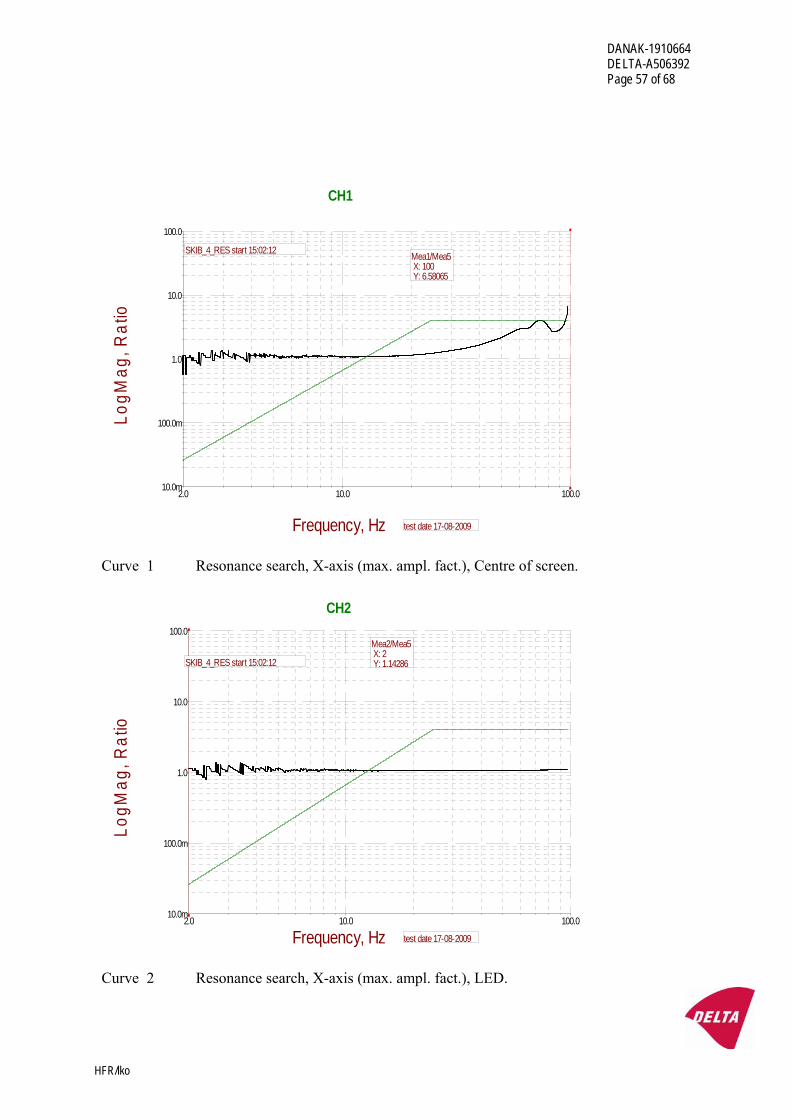
CH1
Mea1/Mea5 X: 100 Y: 6.58065
test date 17-08-2009
SKIB_4_RES start 15:02:12
Curve 1 Resonance search, X-axis (max. ampl. fact.), Centre of screen.
2.0 10.0 100.010.0m
100.0m
1.0
10.0
100.0
Frequency, Hz
LogM
ag, R
atio
CH2
Mea2/Mea5 X: 2 Y: 1.14286
test date 17-08-2009
SKIB_4_RES start 15:02:12
Curve 2 Resonance search, X-axis (max. ampl. fact.), LED.
DANAK-1910664 DELTA-A506392 Page 58 of 68
HFR/lko
2.0 10.0 100.010.0m
100.0m
1.0
10.0
100.0
Frequency, Hz
LogM
ag, R
atio
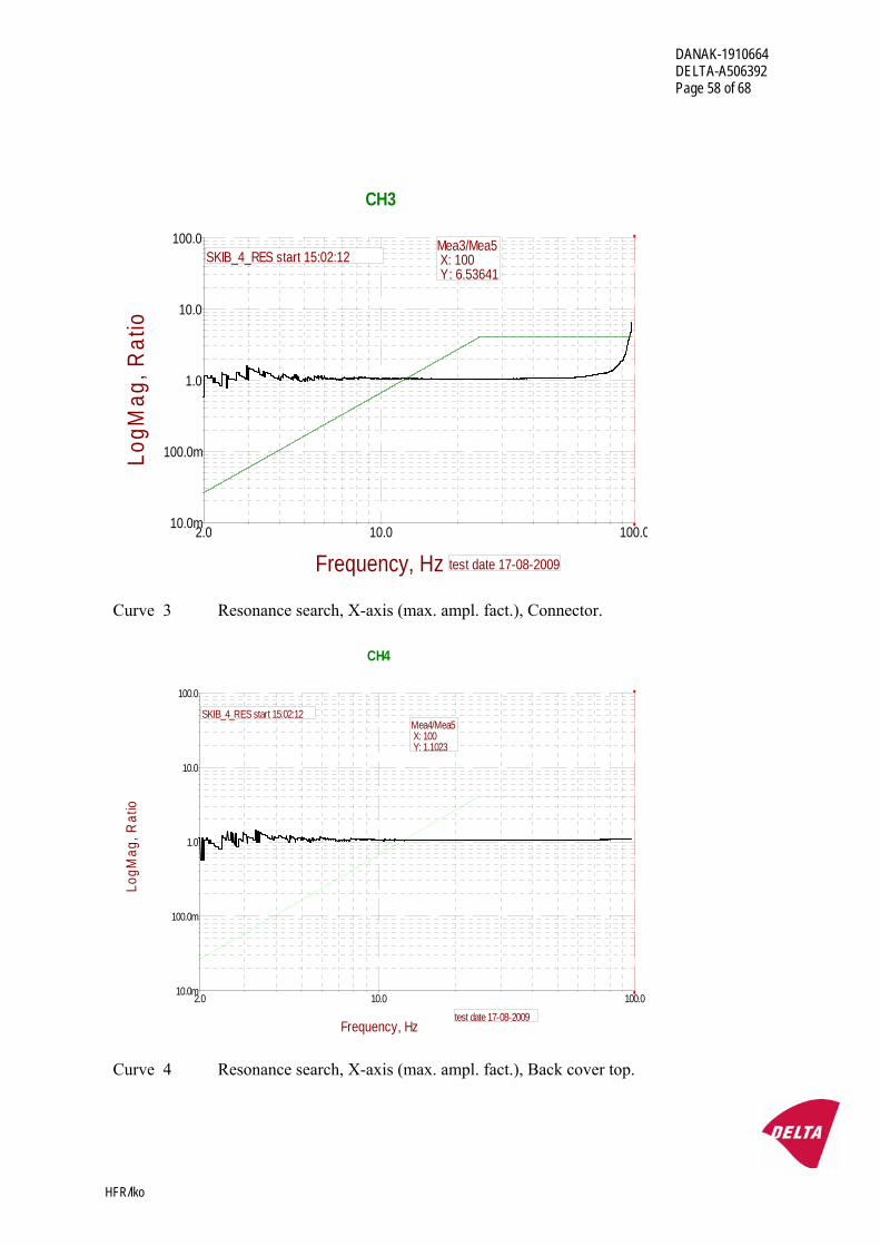
CH3
Mea3/Mea5 X: 100 Y: 6.53641
test date 17-08-2009
SKIB_4_RES start 15:02:12
Curve 3 Resonance search, X-axis (max. ampl. fact.), Connector.
2.0 10.0 100.010.0m
100.0m
1.0
10.0
100.0
Frequency, Hz
LogM
ag, R
atio
CH4
Mea4/Mea5 X: 100 Y: 1.1023
SKIB_4_RES start 15:02:12
test date 17-08-2009
Curve 4 Resonance search, X-axis (max. ampl. fact.), Back cover top.
DANAK-1910664 DELTA-A506392 Page 59 of 68
HFR/lko
2.0 10.0 100.010.0m
100.0m
1.0
10.0
100.0
Frequency, Hz
LogM
ag, R
atio
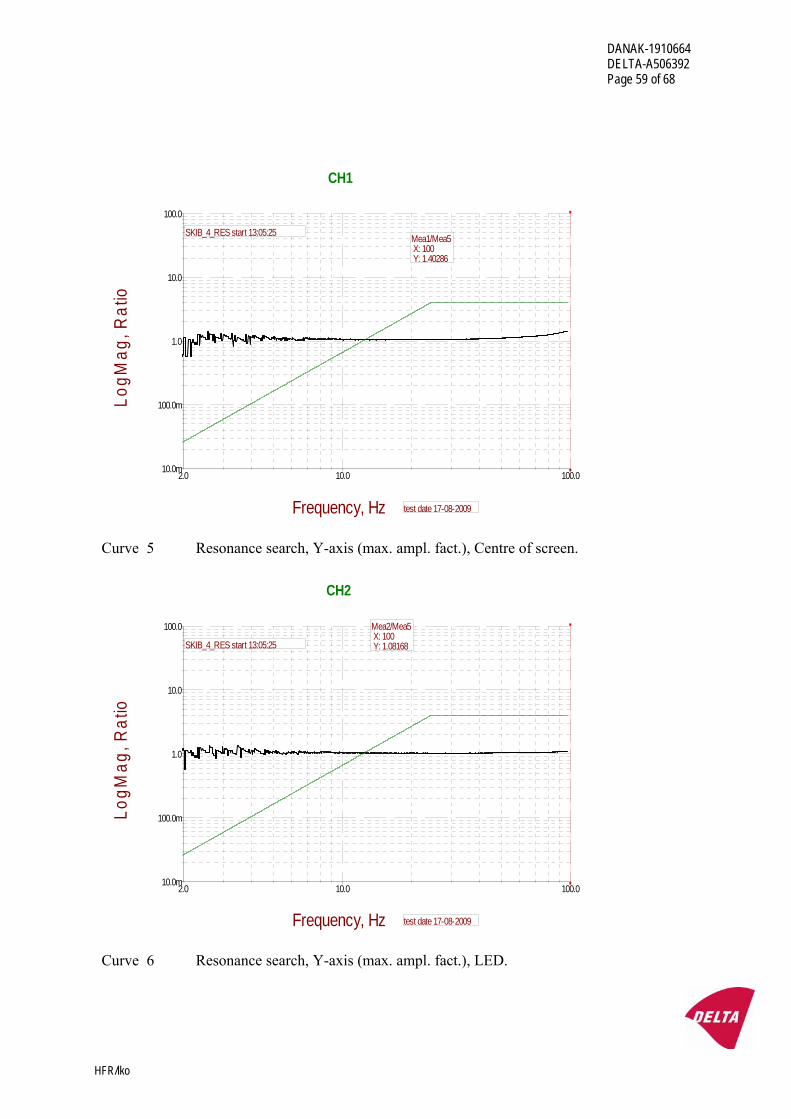
CH1
Mea1/Mea5 X: 100 Y: 1.40286
test date 17-08-2009
SKIB_4_RES start 13:05:25
Curve 5 Resonance search, Y-axis (max. ampl. fact.), Centre of screen.
2.0 10.0 100.010.0m
100.0m
1.0
10.0
100.0
Frequency, Hz
LogM
ag, R
atio
CH2
Mea2/Mea5 X: 100 Y: 1.08168
test date 17-08-2009
SKIB_4_RES start 13:05:25
Curve 6 Resonance search, Y-axis (max. ampl. fact.), LED.
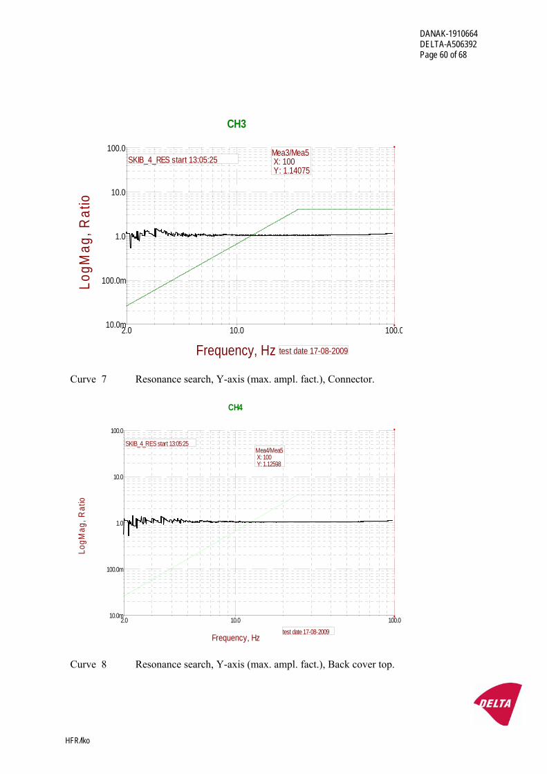
DANAK-1910664 DELTA-A506392 Page 60 of 68
HFR/lko
2.0 10.0 100.010.0m
100.0m
1.0
10.0
100.0
Frequency, Hz
LogM
ag, R
atio
CH3
Mea3/Mea5 X: 100 Y: 1.14075
test date 17-08-2009
SKIB_4_RES start 13:05:25
Curve 7 Resonance search, Y-axis (max. ampl. fact.), Connector.
2.0 10.0 100.010.0m
100.0m
1.0
10.0
100.0
Frequency, Hz
LogM
ag, R
atio
CH4
Mea4/Mea5 X: 100 Y: 1.12598
SKIB_4_RES start 13:05:25
test date 17-08-2009
Curve 8 Resonance search, Y-axis (max. ampl. fact.), Back cover top.
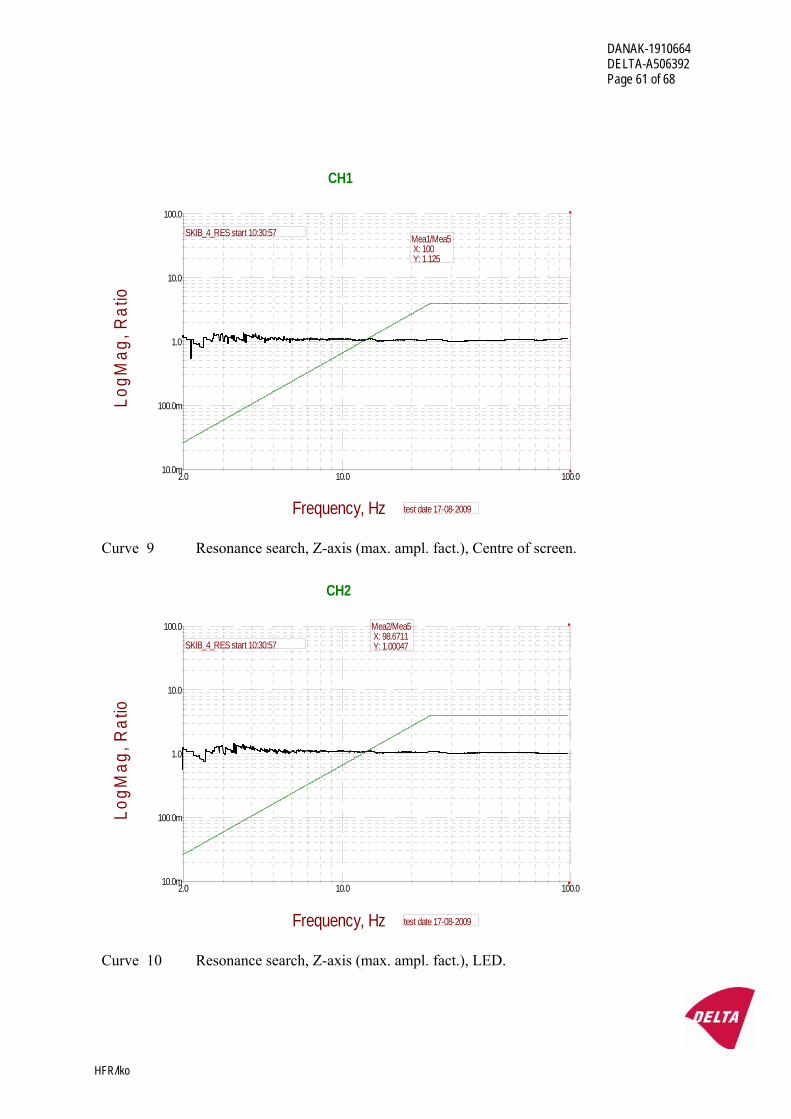
DANAK-1910664 DELTA-A506392 Page 61 of 68
HFR/lko
2.0 10.0 100.010.0m
100.0m
1.0
10.0
100.0
Frequency, Hz
LogM
ag, R
atio
CH1
Mea1/Mea5 X: 100 Y: 1.125
test date 17-08-2009
SKIB_4_RES start 10:30:57
Curve 9 Resonance search, Z-axis (max. ampl. fact.), Centre of screen.
2.0 10.0 100.010.0m
100.0m
1.0
10.0
100.0
Frequency, Hz
LogM
ag, R
atio
CH2
Mea2/Mea5 X: 98.6711 Y: 1.00047
test date 17-08-2009
SKIB_4_RES start 10:30:57
Curve 10 Resonance search, Z-axis (max. ampl. fact.), LED.
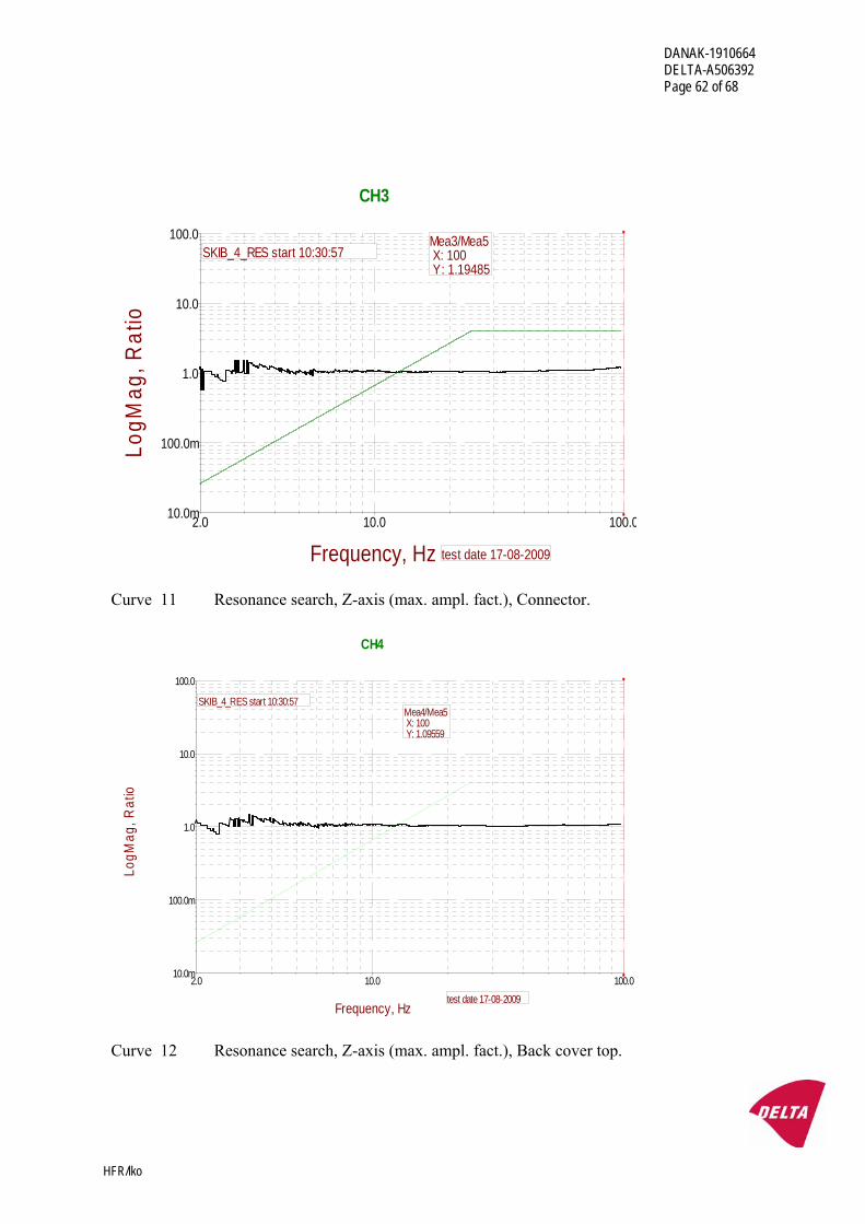
DANAK-1910664 DELTA-A506392 Page 62 of 68
HFR/lko
2.0 10.0 100.010.0m
100.0m
1.0
10.0
100.0
Frequency, Hz
LogM
ag, R
atio
CH3
Mea3/Mea5 X: 100 Y: 1.19485
test date 17-08-2009
SKIB_4_RES start 10:30:57
Curve 11 Resonance search, Z-axis (max. ampl. fact.), Connector.
2.0 10.0 100.010.0m
100.0m
1.0
10.0
100.0
Frequency, Hz
LogM
ag, R
atio
CH4
Mea4/Mea5 X: 100 Y: 1.09559
SKIB_4_RES start 10:30:57
test date 17-08-2009
Curve 12 Resonance search, Z-axis (max. ampl. fact.), Back cover top.
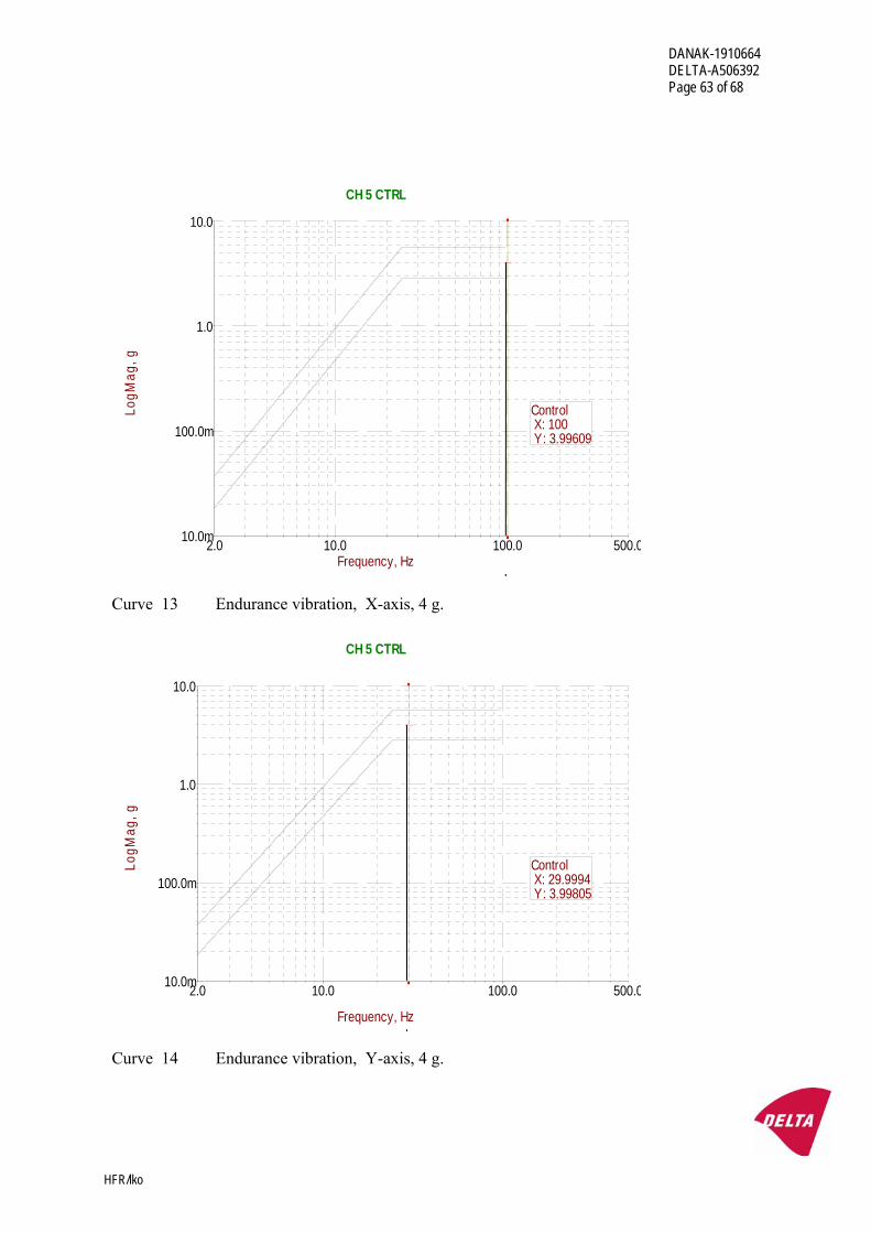
DANAK-1910664 DELTA-A506392 Page 63 of 68
HFR/lko
2.0 500.010.0 100.010.0m
100.0m
1.0
10.0
Frequency, Hz
LogM
ag, g
CH 5 CTRL
Control X: 100 Y: 3.99609
Curve 13 Endurance vibration, X-axis, 4 g.
2.0 500.010.0 100.010.0m
100.0m
1.0
10.0
Frequency, Hz
LogM
ag, g
CH 5 CTRL
Control X: 29.9994 Y: 3.99805
Curve 14 Endurance vibration, Y-axis, 4 g.
DANAK-1910664 DELTA-A506392 Page 64 of 68
HFR/lko
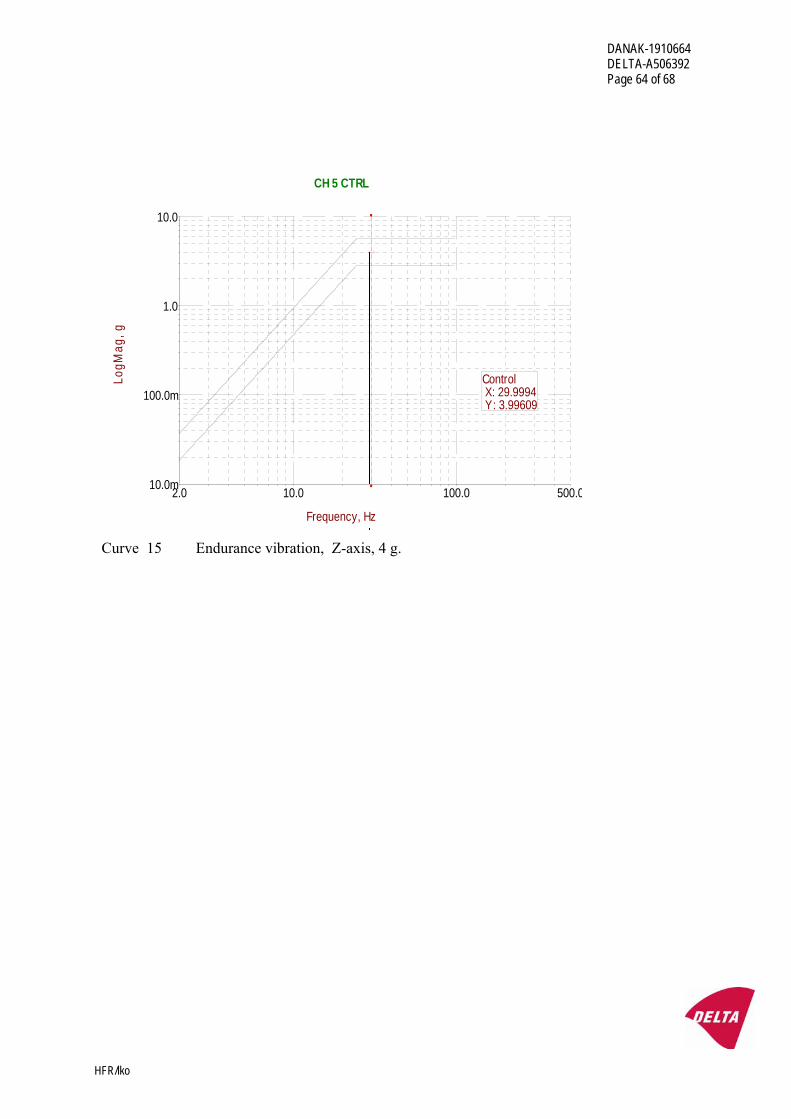
2.0 500.010.0 100.010.0m
100.0m
1.0
10.0
Frequency, Hz
LogM
ag, g
CH 5 CTRL
Control X: 29.9994 Y: 3.99609
Curve 15 Endurance vibration, Z-axis, 4 g.
DANAK-1910664 DELTA-A506392 Page 65 of 68
HFR/lko
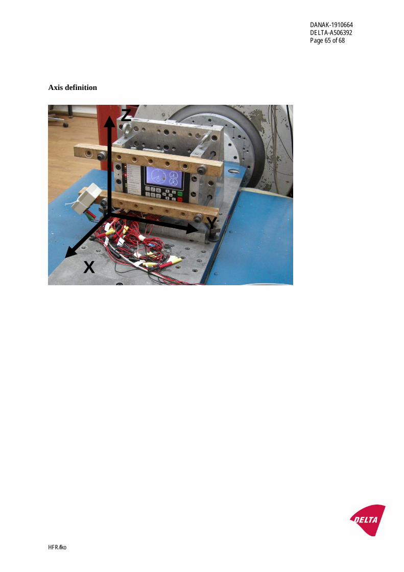
Axis definition
Z
Y
X
DANAK-1910664 DELTA-A506392 Page 66 of 68
HFR/lko
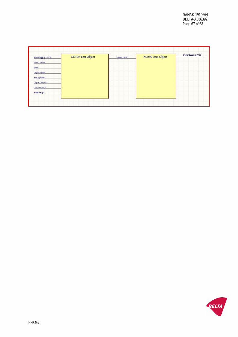
Annex 6
Test setup and functional test procedure (from Client)
(This annex is informative and not part of the accredited report)
DANAK-1910664 DELTA-A506392 Page 67 of 68
HFR/lko
DANAK-1910664 DELTA-A506392 Page 68 of 68
HFR/lko
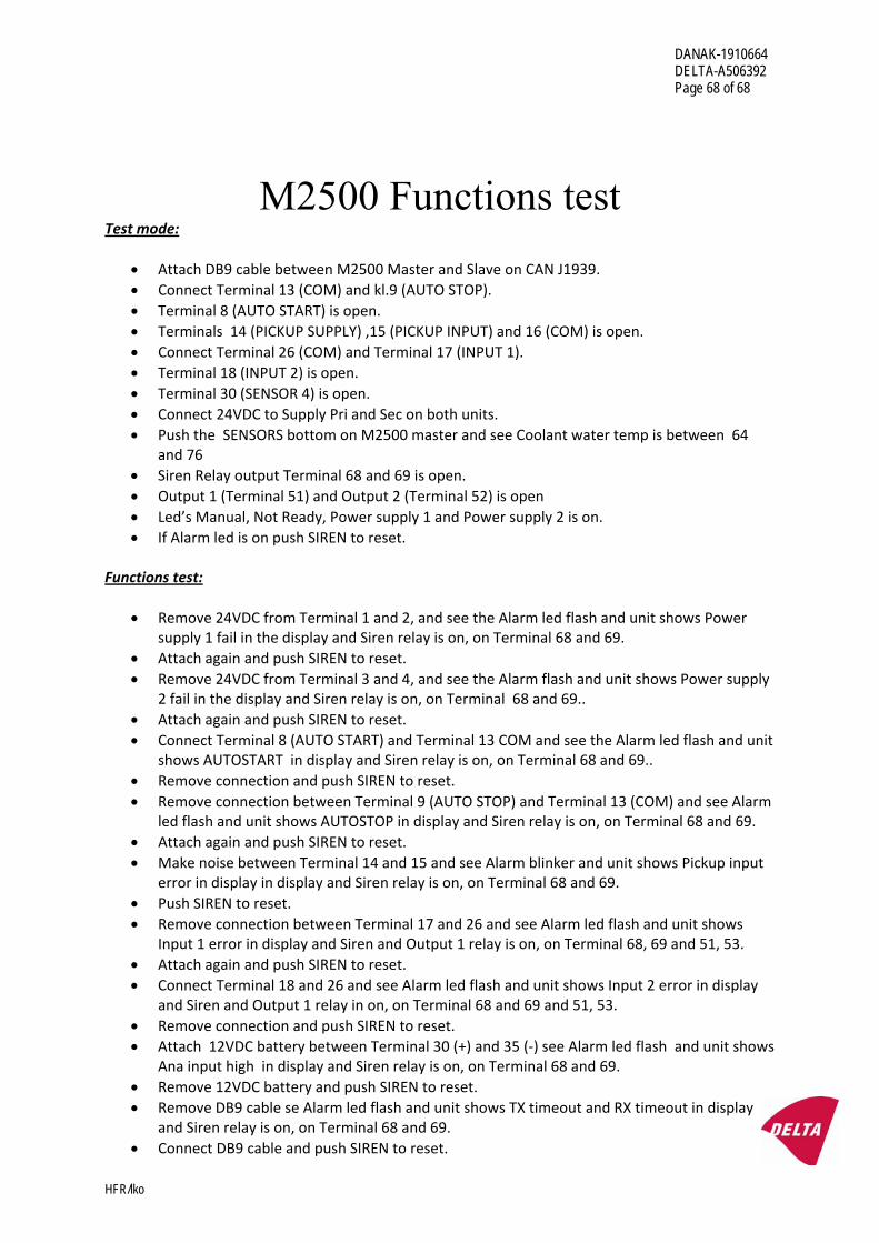
M2500 Functions test Test mode:
• Attach DB9 cable between M2500 Master and Slave on CAN J1939. • Connect Terminal 13 (COM) and kl.9 (AUTO STOP). • Terminal 8 (AUTO START) is open. • Terminals 14 (PICKUP SUPPLY) ,15 (PICKUP INPUT) and 16 (COM) is open. • Connect Terminal 26 (COM) and Terminal 17 (INPUT 1). • Terminal 18 (INPUT 2) is open. • Terminal 30 (SENSOR 4) is open. • Connect 24VDC to Supply Pri and Sec on both units. • Push the SENSORS bottom on M2500 master and see Coolant water temp is between 64
and 76 • Siren Relay output Terminal 68 and 69 is open. • Output 1 (Terminal 51) and Output 2 (Terminal 52) is open • Led’s Manual, Not Ready, Power supply 1 and Power supply 2 is on. • If Alarm led is on push SIREN to reset.
Functions test:
• Remove 24VDC from Terminal 1 and 2, and see the Alarm led flash and unit shows Power supply 1 fail in the display and Siren relay is on, on Terminal 68 and 69.
• Attach again and push SIREN to reset. • Remove 24VDC from Terminal 3 and 4, and see the Alarm flash and unit shows Power supply
2 fail in the display and Siren relay is on, on Terminal 68 and 69.. • Attach again and push SIREN to reset. • Connect Terminal 8 (AUTO START) and Terminal 13 COM and see the Alarm led flash and unit
shows AUTOSTART in display and Siren relay is on, on Terminal 68 and 69.. • Remove connection and push SIREN to reset. • Remove connection between Terminal 9 (AUTO STOP) and Terminal 13 (COM) and see Alarm
led flash and unit shows AUTOSTOP in display and Siren relay is on, on Terminal 68 and 69. • Attach again and push SIREN to reset. • Make noise between Terminal 14 and 15 and see Alarm blinker and unit shows Pickup input
error in display in display and Siren relay is on, on Terminal 68 and 69. • Push SIREN to reset. • Remove connection between Terminal 17 and 26 and see Alarm led flash and unit shows
Input 1 error in display and Siren and Output 1 relay is on, on Terminal 68, 69 and 51, 53. • Attach again and push SIREN to reset. • Connect Terminal 18 and 26 and see Alarm led flash and unit shows Input 2 error in display
and Siren and Output 1 relay in on, on Terminal 68 and 69 and 51, 53. • Remove connection and push SIREN to reset. • Attach 12VDC battery between Terminal 30 (+) and 35 (‐) see Alarm led flash and unit shows
Ana input high in display and Siren relay is on, on Terminal 68 and 69. • Remove 12VDC battery and push SIREN to reset. • Remove DB9 cable se Alarm led flash and unit shows TX timeout and RX timeout in display
and Siren relay is on, on Terminal 68 and 69. • Connect DB9 cable and push SIREN to reset.