Embed Size (px)
Citation preview
Demag AC 40-1
MAIN MENUE Inhalt Contents Contenu
AC 40-1 10/99 03.05.2000 10:58 Uhr Seite 1

Demag AC 40-1
■ Key■ Highlights■ Contents■ Specifications■ Dimensions■ Main boom■ Main boom extension■ Runner and searcher hook for workshop applications■ Technical description
MAIN MENUE
AC 40-1 10/99 03.05.2000 10:58 Uhr Seite 2

Demag AC 40-1
■ Légende■ Highlights■ Contenu■ Caractéristiques■ Encombrement■ Flèche principale■ Rallonge de flèche■ Potence et crochet compact pour utilisation en atelier■ Descriptif technique
MAIN MENUE
AC 40-1 10/99 03.05.2000 10:58 Uhr Seite 3

Demag AC 40-1
■ Zeichenerklärung■ Highlights■ Inhalt■ Technische Daten■ Abmessungen■ Hauptausleger■ Hauptauslegerverlängerung■ Montagespitze und Kopftraverse für Halleneinsätze■ Technische Beschreibung
MAIN MENUE
AC 40-1 10/99 03.05.2000 10:58 Uhr Seite 4

Demag AC 40-1
• Max. Traglast: 40 t bei 3m Ausladung
• Max. Auslegerlänge: 44,2 m mit Verlängerung
• Kurze Fahrgestellänge: 7,09 m
• Kleiner Wenderadius: 6,98 m
• Geringe Durchfahrtshöhe: < 3 m
• Geringes Transportgewicht: 32 t
• Max. capacity: 40 t at 3 m radius
• Max. length of main boom: 44.2 mincl. jib
• Short length of carrier: 7.09 m
• Tight turning radius: 6.98 m
• Low clearance height: < 3 m
• Low transport weight: 32 t
• Charge maxi: 40 t à 3 m de portée
• Longueur de flèche maxi: 44,2 m, rallonge comprise
• Petite longueur de châssis: 7,09 m
• Faible rayon de braquage: 6,98 m
• Petite hauteur: < 3 m
• Faible poids de transport: 32 t
www. dematic.com
MAIN MENUE Inhalt Contents Contenu
AC 40-1 10/99 03.05.2000 10:58 Uhr Seite 5
InhaltContentsContenu
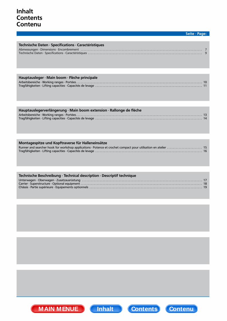
Technische Daten · Specifications · CaractéristiquesAbmessungen · Dimensions · Encombrement . . . . . . . . . . . . . . . . . . . . . . . . . . . . . . . . . . . . . . . . . . . . . . . . . . . . . . . . . . . . . . . . . . . . . . . . . . . . . . . . . . . 7Technische Daten · Specifications · Caractéristiques . . . . . . . . . . . . . . . . . . . . . . . . . . . . . . . . . . . . . . . . . . . . . . . . . . . . . . . . . . . . . . . . . . . . . . . . . . . . . . 9
Hauptausleger · Main boom · Flèche principaleArbeitsbereiche · Working ranges · Portées . . . . . . . . . . . . . . . . . . . . . . . . . . . . . . . . . . . . . . . . . . . . . . . . . . . . . . . . . . . . . . . . . . . . . . . . . . . . . . . . . . . . . . 10Tragfähigkeiten · Lifting capacities · Capacités de levage . . . . . . . . . . . . . . . . . . . . . . . . . . . . . . . . . . . . . . . . . . . . . . . . . . . . . . . . . . . . . . . . . . . . . . . . . 11
Hauptauslegerverlängerung · Main boom extension · Rallonge de flècheArbeitsbereiche · Working ranges · Portées . . . . . . . . . . . . . . . . . . . . . . . . . . . . . . . . . . . . . . . . . . . . . . . . . . . . . . . . . . . . . . . . . . . . . . . . . . . . . . . . . . . . . . 13Tragfähigkeiten · Lifting capacities · Capacités de levage . . . . . . . . . . . . . . . . . . . . . . . . . . . . . . . . . . . . . . . . . . . . . . . . . . . . . . . . . . . . . . . . . . . . . . . . . 14
Montagespitze und Kopftraverse für HalleneinsätzeRunner and searcher hook for workshop applications · Potence et crochet compact pour utilisation en atelier . . . . . . . . . . . . . . . . . . . . . . . . 15Tragfähigkeiten · Lifting capacities · Capacités de levage . . . . . . . . . . . . . . . . . . . . . . . . . . . . . . . . . . . . . . . . . . . . . . . . . . . . . . . . . . . . . . . . . . . . . . . . . 16
Technische Beschreibung · Technical description · Descriptif techniqueUnterwagen · Oberwagen · Zusatzausrüstung . . . . . . . . . . . . . . . . . . . . . . . . . . . . . . . . . . . . . . . . . . . . . . . . . . . . . . . . . . . . . . . . . . . . . . . . . . . . . . . . . . 17Carrier · Superstructure · Optional equipment . . . . . . . . . . . . . . . . . . . . . . . . . . . . . . . . . . . . . . . . . . . . . . . . . . . . . . . . . . . . . . . . . . . . . . . . . . . . . . . . . . . 18Châssis · Partie supérieure · Equipements optionnels . . . . . . . . . . . . . . . . . . . . . . . . . . . . . . . . . . . . . . . . . . . . . . . . . . . . . . . . . . . . . . . . . . . . . . . . . . . . . 19
Seite · Page:
MAIN MENUE Inhalt Contents Contenu
AC 40-1 10/99 03.05.2000 10:58 Uhr Seite 6

AbmessungenDimensionsEncombrement
Bereifung NiveauType of tyres Level A B C DType de pneus Niveau
Straße14.00 Road 3195 3085 340 1490
Route
Abgelassen14.00 Lowered 3115 3005 260 1410
Rabaissée
Straße445 / 65 Road 3095 2985 240 1390
Route
Abgelassen445 / 65 Lowered 2995 2885 140 1290
Rabaissée
MAIN MENUE Inhalt Contents Contenu
AC 40-1 10/99 03.05.2000 10:58 Uhr Seite 7
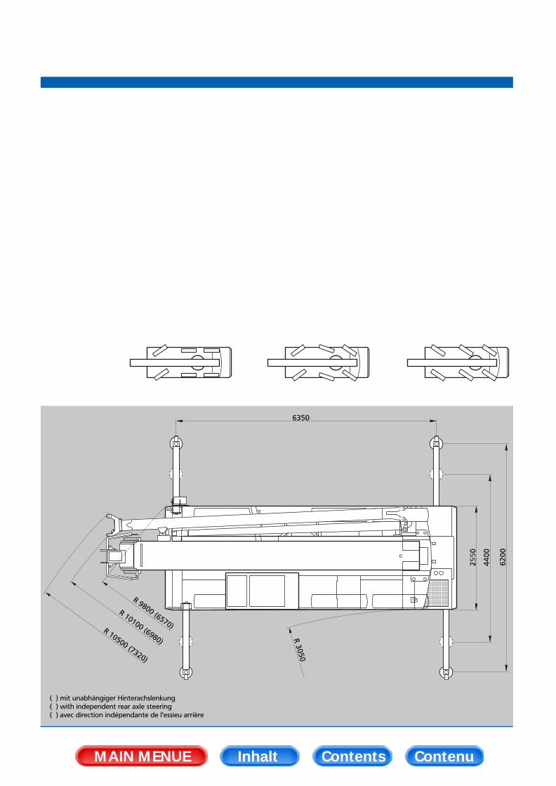
( ) mit unabhängiger Hinterachslenkung( ) with independent rear axle steering( ) avec direction indépendante de l’essieu arrière
MAIN MENUE Inhalt Contents Contenu
AC 40-1 10/99 03.05.2000 10:58 Uhr Seite 8
Technische DatenSpecificationsCaractéristiques
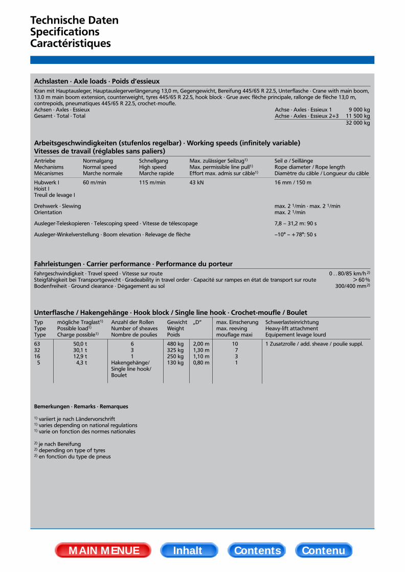
Achslasten · Axle loads · Poids d’essieuxKran mit Hauptausleger, Hauptauslegerverlängerung 13,0 m, Gegengewicht, Bereifung 445/65 R 22.5, Unterflasche · Crane with main boom,13.0 m main boom extension, counterweight, tyres 445/65 R 22.5, hook block · Grue avec flèche principale, rallonge de flèche 13,0 m,contrepoids, pneumatiques 445/65 R 22.5, crochet-moufle.Achsen · Axles · Essieux Achse · Axles · Essieux 1 9 000 kgGesamt · Total · Total Achse · Axles · Essieux 2+3 11 500 kg
32 000 kg
Arbeitsgeschwindigkeiten (stufenlos regelbar) · Working speeds (infinitely variable)Vitesses de travail (réglables sans paliers)Antriebe Normalgang Schnellgang Max. zulässiger Seilzug1) Seil ø / SeillängeMechanisms Normal speed High speed Max. permissible line pull1) Rope diameter / Rope lengthMécanismes Marche normale Marche rapide Effort max. admis sur câble1) Diamètre du câble / Longueur du câble
Hubwerk I 60 m/min 115 m/min 43 kN 16 mm / 150 mHoist ITreuil de levage I
Drehwerk · Slewing max. 2 1/min · max. 2 1/minOrientation max. 2 1/min
Ausleger-Teleskopieren · Telescoping speed · Vitesse de télescopage 7,8 – 31,2 m: 90 s
Ausleger-Winkelverstellung · Boom elevation · Relevage de flèche –10° – +78°: 50 s
Fahrleistungen · Carrier performance · Performance du porteurFahrgeschwindigkeit · Travel speed · Vitesse sur route 0 . . 80/85 km/h 2)
Steigfähigkeit bei Transportgewicht · Gradeability in travel order · Capacité sur rampes en état de transport sur route > 60 %Bodenfreiheit · Ground clearance · Dégagement au sol 300/400 mm2)
Unterflasche / Hakengehänge · Hook block / Single line hook · Crochet-moufle / BouletTyp mögliche Traglast1) Anzahl der Rollen Gewicht „D“ max. Einscherung SchwerlasteinrichtungType Possible load1) Number of sheaves Weight max. reeving Heavy-lift attachmentType Charge possible1) Nombre de poulies Poids mouflage maxi Equipement levage lourd
63 50,0 t 6 480 kg 2,00 m 10 1 Zusatzrolle / add. sheave / poulie suppl.32 30,1 t 3 325 kg 1,30 m 1716 12,9 t 1 250 kg 1,10 m 1315 14,3 t Hakengehänge/ 130 kg 0,80 m 11
Single line hook/Boulet
Bemerkungen · Remarks · Remarques
1) variiert je nach Ländervorschrift1) varies depending on national regulations1) varie on fonction des normes nationales
2) je nach Bereifung2) depending on type of tyres2) en fonction du type de pneus
MAIN MENUE Inhalt Contents Contenu
AC 40-1 10/99 03.05.2000 10:58 Uhr Seite 9
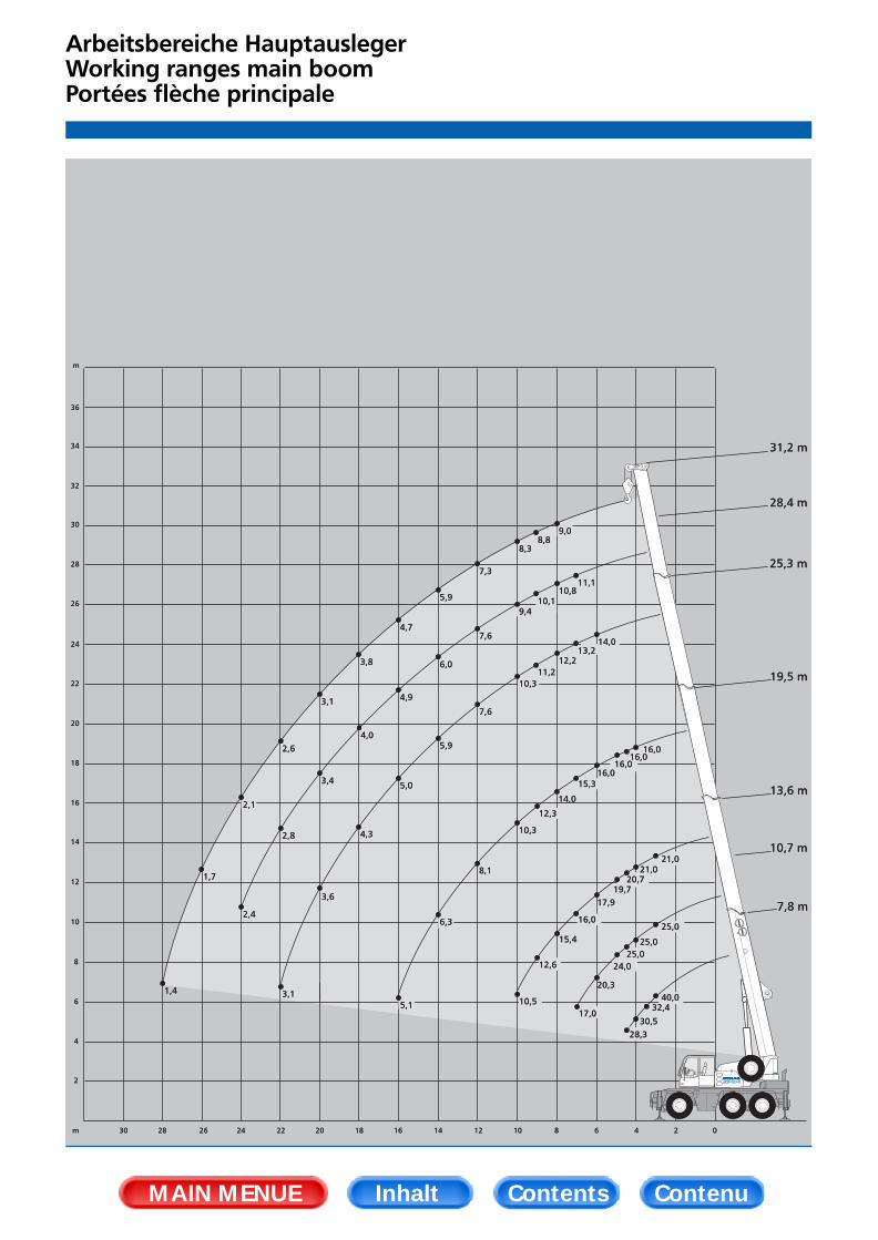
Arbeitsbereiche HauptauslegerWorking ranges main boom Portées flèche principale
MAIN MENUE Inhalt Contents Contenu
AC 40-1 10/99 03.05.2000 10:58 Uhr Seite 10

Tragfähigkeiten HauptauslegerLifting capacities main boomCapacités de levage flèche principale
360°AusladungRadiusPortée m
Hauptausleger · Main boom · Flèche principale Hauptausleger · Main boom · Flèche principale
1m131313,51414,515161718191012141618202224262830Traglast · CapacitiesCharges 1)
* 0° nach hinten* 0° over rear* 0° sur l’arrière
** nur stationär** only stationary** uniquement stationnaire
1) horizontal1) with horizontal boom1) avec flèche horizontale
1m33
3,54
4,556789
1012141618202224262830
Traglast · CapacitiesCharges 1)
7,8t,0
40,034,332,430,528,3
-,0-,0-,0-,0-,0-,0-,0-,0-,0-,0-,0-,0-,0-,0-,0-,0
20,0
10,7t,0-,0
25,025,025,025,024,020,317,0
-,0-,0-,0-,0-,0-,0-,0-,0-,0-,0-,0-,0-,0
14,0
13,6t,0-,0
21,021,021,020,719,717,916,015,412,610,5
-,0-,0-,0-,0-,0-,0-,0-,0-,0-,0
8,8
19,5t,0-,0-,0-,0
16,016,016,016,015,314,012,310,3
8,16,35,1-,0-,0-,0-,0-,0-,0-,0
4,5
25,3t,0-,0-,0-,0-,0-,0-,0
14,013,212,211,210,3
7,65,95,04,33,53,0-,0-,0-,0-,0
2,5
28,4t,0-,0-,0-,0-,0-,0-,0-,0
11,110,810,1
9,47,66,04,94,03,42,82,3-,0-,0-,0
1,8
31,2t,0-,0-,0-,0-,0-,0-,0-,0-,09,08,88,37,35,94,73,83,12,62,11,71,4-,0
1,1
7,8t,0-,0
14,512,911,510,4
-,0-,0-,0-,0-,0-,0-,0-,0-,0-,0-,0-,0-,0-,0-,0-,0
8,0
10,7t,0-,0
14,012,411,110,0
9,07,56,1-,0-,0-,0-,0-,0-,0-,0-,0-,0-,0-,0-,0-,0
4,0
13,6t,0-,0
15,113,412,111,010,0
8,47,25,94,84,1-,0-,0-,0-,0-,0-,0-,0-,0-,0-,0
3,0
*
* * *
Bemerkungen · Remarks · Remarques
6,35 x 6,20 m 360° 0°*
360°AusladungRadiusPortée m
Hauptausleger · Main boom · Flèche principale Hauptausleger · Main boom · Flèche principale
1m1414,5151617181910121416Traglast · CapacitiesCharges 1)
1m14
14,5151617181910121416
Traglast · CapacitiesCharges 1)
7,8t,0
11,89,8-,0-,0-,0-,0-,0-,0-,0-,0-,0
8,0
10,7t,0
11,29,27,75,74,3-,0-,0-,0-,0-,0-,0
2,8
13,6t,0
12,610,5
8,96,75,34,33,63,0-,0-,0-,0
2,1
19,5t,0
12,910,8
9,27,05,54,53,83,22,31,71,3
-,0
7,8t,0-,05,9-,0-,0-,0-,0-,0-,0-,0-,0-,0
4,8
10,7t,0-,05,44,73,62,8-,0-,0-,0-,0-,0-,0
1,9
13,6t,0-,06,65,84,73,83,12,62,2-,0-,0-,0
1,3
6,35 x 2,34 m 360° 360°**
DIN/ISODIN/ISO
DIN/ISODIN/ISO
MAIN MENUE Inhalt Contents Contenu
AC 40-1 10/99 03.05.2000 10:58 Uhr Seite 11

360°AusladungRadiusPortée m
AusladungRadiusPortée
Hauptausleger · Main boom · Flèche principale
1m1313,51414,5151617181910121416182022242628Traglast · CapacitiesCharges 1)
1m3
3,54
4,556789
10121416182022242628
Traglast · CapacitiesCharges 1)
7,8t,0
34,331,228,323,8
-,0-,0-,0-,0-,0-,0-,0-,0-,0-,0-,0-,0-,0-,0-,0
20,0
10,7t,0
25,025,025,023,018,413,0
9,8-,0-,0-,0-,0-,0-,0-,0-,0-,0-,0-,0-,0
7,0
13,6t,0
21,021,021,020,718,014,411,1
8,97,36,2-,0-,0-,0-,0-,0-,0-,0-,0-,0
5,2
19,5t,0-,0-,0
16,016,016,014,211,4
9,27,66,44,83,73,0-,0-,0-,0-,0-,0-,0
2,5
25,3t,0-,0-,0-,0-,0-,0
13,610,9
8,77,76,54,93,83,02,52,11,7-,0-,0-,0
1,5
28,4t,0-,0-,0-,0-,0-,0-,0
10,88,87,46,34,73,62,82,31,81,51,2-,0-,0
0,8
31,2t,0-,0-,0-,0-,0-,0-,0-,08,87,26,14,53,42,72,11,71,31,00,80,6
-,0
6,35 x 4,40 m 360° DIN/ISO
MAIN MENUE Inhalt Contents Contenu
AC 40-1 10/99 03.05.2000 10:58 Uhr Seite 12

Arbeitsbereiche HauptauslegerverlängerungWorking ranges main boom extensionPortées rallonge de flèche
MAIN MENUE Inhalt Contents Contenu
AC 40-1 10/99 03.05.2000 10:58 Uhr Seite 13

Tragfähigkeiten HauptauslegerverlängerungLifting capacities main boom extensionCapacités de levage rallonge de flèche
AusladungRadiusPortée
Verlängerung · Extension · Rallonge de flèche
1m1819101214161820222426283032343638
t,06,56,25,95,44,94,54,03,32,82,31,91,6-,0-,0-,0-,0-,0
t,0-,0-,04,24,03,83,73,53,42,92,4-,0-,0-,0-,0-,0-,0-,0
7,1 m0° 30°
13,0 m0° 30°t,0-,0-,03,63,33,02,82,62,42,32,12,01,71,51,21,0-,0-,0
t,0-,0-,0-,0-,0-,02,22,12,01,91,91,81,81,6-,0-,0-,0-,0
6,35 x 6,20 m 360°
25,3 m Hauptausleger · Main boom · Flèche principale
AusladungRadiusPortée
Verlängerung · Extension · Rallonge de flèche
1m1819101214161820222426283032343638
t,06,56,25,94,73,62,82,31,81,51,20,90,7-,0-,0-,0-,0-,0
t,0-,0-,04,24,03,83,12,52,01,61,3-,0-,0-,0-,0-,0-,0-,0
7,1 m0° 30°
13,0 m0° 30°t,0-,0-,03,63,33,02,82,41,91,61,31,00,80,6-,0-,0-,0-,0
t,0-,0-,0-,0-,0-,02,22,12,01,91,61,31,00,8-,0-,0-,0-,0
6,35 x 4,40 m 360°
25,3 m Hauptausleger · Main boom · Flèche principale
1m1819101214161820222426283032343638
t,0-,0-,05,04,84,64,44,03,32,72,21,81,51,20,90,7-,0-,0
t,0-,0-,0-,03,93,73,53,33,12,92,42,01,61,3-,0-,0-,0-,0
t,0-,0-,0-,03,02,92,82,72,52,42,21,91,61,31,10,90,7-,0
t,0-,0-,0-,0-,0-,0-,02,12,01,91,91,81,81,61,31,0-,0-,0
31,2 m Hauptausleger · Main boom · Flèche principale
1m1819101214161820222426283032343638
t,0-,0-,05,04,63,52,82,21,71,41,10,80,6-,0-,0-,0-,0-,0
t,0-,0-,0-,03,93,73,12,52,01,61,31,00,7-,0-,0-,0-,0-,0
t,0-,0-,0-,03,02,92,82,31,81,51,20,90,7-,0-,0-,0-,0-,0
t,0-,0-,0-,0-,0-,0-,02,12,01,81,51,21,00,7-,0-,0-,0-,0
31,2 m Hauptausleger · Main boom · Flèche principale
DIN/ISODIN/ISO
MAIN MENUE Inhalt Contents Contenu
AC 40-1 10/99 03.05.2000 10:58 Uhr Seite 14

Montagespitze für HalleneinsätzeRunner for workshop applicationsPotence pour utilisation en atelier
MAIN MENUE Inhalt Contents Contenu
AC 40-1 10/99 03.05.2000 10:58 Uhr Seite 15
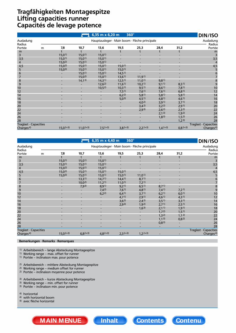
Tragfähigkeiten MontagespitzeLifting capacities runnerCapacités de levage potence
360°AusladungRadiusPortée m
AusladungRadiusPortée
Hauptausleger · Main boom · Flèche principale
1m1313,51414,5151617181910121416182022242628Traglast · CapacitiesCharges 4)
1m3
3,54
4,556789
10121416182022242628
Traglast · CapacitiesCharges 4)
7,8t,0
15,015,015,015,015,0
-,0-,0-,0-,0-,0-,0-,0-,0-,0-,0-,0-,0-,0-,0
15,0
10,7t,0
15,015,015,015,015,015,015,014,1
-,0-,0-,0-,0-,0-,0-,0-,0-,0-,0-,0
11,0
13,6t,0
15,015,015,015,015,015,015,014,312,610,5
-,0-,0-,0-,0-,0-,0-,0-,0-,0
7,5
19,5t,0-,0-,0-,0
15,015,014,513,612,511,610,3
7,56,25,0-,0-,0-,0-,0-,0-,0
3,8
25,3t,0-,0-,0-,0-,0-,0-,0
11,911,010,2
9,57,65,84,54,03,42,9-,0-,0-,0
2,2
28,4t,0-,0-,0-,0-,0-,0-,0-,09,89,18,67,65,84,83,93,22,62,11,8-,0
1,4
31,2t,0-,0-,0-,0-,0-,0-,0-,0-,08,37,86,85,84,63,72,92,31,91,51,2
0,8
6,35 m x 6,20 m 360° DIN/ISO
1)
1)
2)
2)
3)
2+3)
1)
1)
1)
1)
1)
1)
2)
3)
2+3)
1)
1)
1)
1)
1)
1)
1)
1)
2)
2)
2+3)
1)
1)
1)
1)
1)
1)
1)
1)
2)
3)
2+3)
1)
1)
1)
1)
1)
1)
1)
2)
2)
3)
2+3)
1)
1)
1)
1)
1)
1)
1)
2)
2)
3)
3)
2+3)
1)
1)
1)
1)
1)
1)
1)
2)
2)
2)
3)
2+3)
360°AusladungRadiusPortée m
AusladungRadiusPortée
Hauptausleger · Main boom · Flèche principale
1m1313,51414,5151617181910121416182022242628Traglast · CapacitiesCharges 4)
1m3
3,54
4,556789
10121416182022242628
Traglast · CapacitiesCharges 4)
7,8t,0
15,015,015,015,015,0
-,0-,0-,0-,0-,0-,0-,0-,0-,0-,0-,0-,0-,0-,0
15,0
10,7t,0
15,015,015,015,015,013,310,0
7,9-,0-,0-,0-,0-,0-,0-,0-,0-,0-,0-,0
6,8
13,6t,0
15,015,015,015,015,014,711,2
8,97,46,2-,0-,0-,0-,0-,0-,0-,0-,0-,0
4,8
19,5t,0-,0-,0-,0
15,015,014,411,0
9,27,66,44,73,62,9-,0-,0-,0-,0-,0-,0
2,3
25,3t,0-,0-,0-,0-,0
11,08,77,26,54,83,72,92,41,91,6-,0-,0-,0-,0-,0
1,2
28,4t,0-,0-,0-,0-,0-,0-,0-,08,77,46,24,63,52,72,11,71,31,10,8-,0
-,0
31,2t,0-,0-,0-,0-,0-,0-,0-,0-,07,26,04,33,32,51,91,51,10,8-,0-,0
-,0
6,35 m x 4,40 m 360° DIN/ISO
1)
1)
2)
2)
3)
2+3)
1)
1)
1)
1)
1)
1)
2)
3)
2+3)
1)
1)
1)
1)
1)
1)
1)
1)
2)
2)
2+3)
1)
1)
1)
1)
1)
1)
1)
1)
2)
3)
2+3)
1)
1)
1)
1)
1)
1)
1)
2)
2)
3)
2+3)
1)
1)
1)
1)
1)
1)
1)
2)
2)
3)
3)
1)
1)
1)
1)
1)
1)
1)
2)
2)
1) Arbeitsbereich – lange Absteckung Montagespitze1) Working range – max. offset for runner1) Portée – inclinaison max. pour potence
2) Arbeitsbereich – mittlere Absteckung Montagespitze2) Working range – medium offset for runner2) Portée – inclinaison moyenne pour potence
3) Arbeitsbereich – kurze Absteckung Montagespitze3) Working range – min. offset for runner3) Portée – inclinaison min. pour potence
4) horizontal4) with horizontal boom4) avec flèche horizontal
Bemerkungen · Remarks · Remarques
MAIN MENUE Inhalt Contents Contenu
AC 40-1 10/99 03.05.2000 10:58 Uhr Seite 16

Technische Beschreibung
UnterwagenAntrieb/Lenkung 6 x 4 x 6Rahmen Geschlossenes Kastenprofil mit integrierten Abstützkästen aus hochfestem Feinkornbaustahl.Abstützung 4-Punkt-Abstützung, hydraulisch horizontal und vertikal auszufahrende Abstützungen.Motor Wassergekühlter 6-Zylinder Daimler-Benz OM 906 LA „EURO II“, Leistung nach DIN: 205 kW (279 PS),
max. Drehmoment 1100 Nm bei 1300 1/min. Inhalt des Kraftstoffbehälters: 300 l.Getriebe Allison-Automatikgetriebe mit Drehmomentwandler, 6 Vorwärts- und 1 Rückwärtsgang,
Verteilergetriebe mit Geländestufe und Längsdifferentialsperre.Achsen Achse 1: Außen-Planetenachse mit Querdifferentialsperre, lenkbar; Achse 2: Laufachse, lenkbar bei
unabhängiger Hinterachslenkung; Achse 3: Außen-Planetenachse mit Querdifferentialsperre, lenkbarbei unabhängiger Hinterachslenkung.
Federung Alle Achsen hydropneumatisch gefedert und hydraulisch blockierbar.Bereifung 6-fach, 445/65 R 22.5.Fahrgeschwindigkeit 80 km/h.Lenkung ZF-Hydro-Zweikreis-Lenkung mit mechanischer Lenkbegrenzung. 1 motorgetriebene Lenkhauptpumpe,
1 Notlenkpumpe. Unabhängige Hinterachslenkung.Bremsen Betriebsbremse: Zweikreis-Druckluft-Bremsanlage; Feststellbremse: Federspeicherbremse; Dauerbremse:
Auspuffklappenbremse, Konstantdrossel.Elektrische Anlage Betriebsspannung 24 V, Drehstrom-Lichmaschine 80 A, 2 Batterien 12 V/120 Ah. Beleuchtung nach
EG-Richtlinien.
OberwagenHauptausleger Grundkasten und 4 Teleskope aus Feinkornbaustahl, unter Teillast teleskopierbar, beulsteifer Demag-
Ovaloidquerschnitt.Gegengewicht im Oberwagen integriert.Hydraulikanlage Antrieb über Unterwagen-Motor, 1 Axialkolben-Verstellpumpe für 3 gleichzeitige, unabhängige
Arbeitsbewegungen, separate Konstantpumpe für das Drehwerk.Hubwerk Axialkolben-Konstantmotor, Hubwerkstrommel mit integriertem Planetengetriebe und federbelasteter
Lamellenbremse.Drehwerk Hydromotor mit Planetengetriebe, fußbetätigte Betriebsbremse, federbelastete Haltebremse.
Drehgeschwindigkeit stufenlos.Wippwerk 1 Differentialzylinder mit vorgesteuertem Senk-Bremsventil.Krankabine Großräumige Ganzstahl-Komfortkabine mit Schiebetür und großem ausstellbarem Frontfenster,
Dachfenster mit Panzerglas, höhenverstellbarer Fahrersitz, Betätigungs- und Kontrollinstrumente füralle Kranfunktionen, Front- und Dachscheibenwischer mit Intervallschaltung und Scheibenwaschanlage.
Sicherheitseinrichtungen Elektronischer Lastmomentbegrenzer und Graphik-Display zur digitalen Anzeige von Hakenlast, Nenn-traglast, Auslegerlänge, Auslegerwinkel, Ausladung. Integrierte prozentuale Anzeige der Teleskop-ausfahrfolgen. Weitere Sicherheitseinrichtungen: Hub- und Senkendschaltung, Druckbegrenzungsventil,Rohrbruchsicherungen.
ZusatzausrüstungAntrieb/Lenkung 6 x 6 x 6.Bereifung 14.00 R 25 oder 17.5 R 25.Hauptauslegerverlängerung Seitlich klappbar, 1- bzw. 2-teilige Spitze, 7,1 m bzw. 13,0 m Länge. Einstellbereich 0° und 30°.Schwerlasteinrichtung 1 Zusatzrolle am Hauptauslegerkopf.Schwerlast-Montagespitze Länge 1,20 m, 3-rollig mit einstellbaren Arbeitswinkeln für den Halleneinsatz.KopftraverseKlimaanlageKühlfach
Änderungen vorbehalten! 10 /99
MAIN MENUE Inhalt Contents Contenu
AC 40-1 10/99 03.05.2000 10:58 Uhr Seite 17

Technical description
CarrierDrive/steering 6 x 4 x 6Frame Monobox main frame with outrigger boxes integral, of high-strength fine-grain structural steel.Outriggers 4 hydraulically telescoping outrigger beams with hydraulic jack legs.Engine Daimler Benz OM 906 LA „EURO II“ water-cooled 6-cylinder engine, output to DIN: 205 kW (279 hp),
max. torque 1100 Nm at 1300 1/min. Fuel tank capacity: 300 l.Transmission Allison automatic transmission with torque-converter, 6 forward speeds and 1 reverse, transfer case
with off-road range and longitudinal differential lock-out control.Axles Axle 1: with ext. planetary hubs, steering, transverse differential locks; axle 2: non-driving, steering for
crab steer mode; axle 3: with ext. planetary hubs, steering for crab steer mode, transverse differentiallocks.
Suspension Hydropneumatic suspension, blockable hydraulically.Wheels and tyres 6 wheels fitted with 445/65 R 22.5 tyres.Travel speed 80 km/h.Steering ZF dual-circuit hydraulic steering with mech. steering end stop. 1 engine-driven master steering pump,
1 emergency steering pump. Independent rear axle steering.Brakes Service brake: dual-line air system. Parking brake: spring-loaded type. Sustained action brake: engine
exhaust brake and constant decompression valve.Electrical equipment 24 V system, 3-phase alternator 80 A, 2 batteries 12 V/120 Ah. Lighting in compliance with EC-direc-
tives.
SuperstructureMain boom Boom base and 4 telescopic sections, fabricated from fine-grain structural steel, telescoping with partial
load, anti-deflection Demag ovaloid design.Counterweight Integrated into superstructure.Hydraulic system Powered by carrier engine, 1 variable-displacement axial piston pump to enable 3 simultaneous,
independent working movements, separate fixed-displacement pump for slew unit.Hoist Fixed-displacement axial-piston motor, hoist drum with planetary reduction integral and spring-applied
multi-disk brake.Slew unit Hydraulic motor with planetary gear reducer, pedal-operated service brake and spring-applied holding
brake. Slewing speed infinitely variable.Boom elevation 1 differential cylinder with pilot-controlled lowering brake valve.Crane cab Spacious all-steel comfortable cab with sliding door, large folding-out windscreen, roof window with
armoured glass, vertically adjustable operator’s seat, controls and instrumentation for all crane move-ments, washer and interval control wiper for windscreen and roof window.
Safety devices Electronic safe load indicator with graphic display and digital readout for hook load, rated load, boomlength, boom angle, load radius. Integrated display to indicate the percentage of tele sequence, limitswitches on hoist and lowering motions, pressure-relief and safety holding valves.
Optional equipmentDrive/steering 6 x 6 x 6.Wheels and tyres 14.00 R 25 or 17.5 R 25.Main boom extension Side-folding 1 or 2-part jib, 7.1 m or 13.0 m. 0° and 30° offset.Heavy-lift attachment 1 additional sheave on boom head.Heavy-lift runner 1.20 m long, 3-sheave with several offset positions for working inside buildings.Searcher hookAir-conditioningCool box
Subject to change without notice! 10 /99
MAIN MENUE Inhalt Contents Contenu
AC 40-1 10/99 03.05.2000 10:58 Uhr Seite 18

Descriptif technique
ChâssisEntraînement/direction 6 x 4 x 6.Charpente Construction sous forme de caissons soudés fermés, comprenant les logements des poutres de calage
et réalisés en tôle d’acier de construction de haute résistance à grains fins.Calage 4 poutres hydrauliques à extension horizontale et vérins verticaux.Moteur Moteur 6 cylindres Daimler-Benz OM 906 LA „EURO II“, à refroidissement par eau. Puissance suivant
DIN: 205 kW (279 CV). Couple maxi 1100 Nm à 1300 1/min. Réservoir de carburant: 300 l.Transmission Boîte automatique Allison avec convertisseur de couple, 6 vitesses AV, 1 AR. Boîte de transfert à
rapport chantier et différentiel longitudinal verrouillable.Ponts et essieux Essieu 1: à planétaires ext., directeur, différentiel transversal verrouillable; essieu 2: non-moteur, direc-
teur pour marche en crabe; essieu 3: à planétaires ext., directeur pour marche en crabe, différentieltransversal verrouillable.
Suspension Suspension hydropneumatique sur tous les essieux avec blocage hydraulique.Roues et pneumatiques 6 x 445/65 R 22.5.Vitesse sur route 80 km/h.Direction ZF à servo-commande hydraulique à double circuit, avec limiteur mécanique, 1 pompe principale
entrainée par le moteur, 1 pompe de secours. Direction indépendante des essieux AR.Freinage Frein de service: pneumatique, à double circuit. Frein de stationnement: cylindres de frein à ressort.
Frein continu: frein sur échappement et soupape d’étranglement.Installation électrique Système 24 V, alternateur 80 A, 2 batteries 12 V/120 Ah. Eclairage selon normes CE.
Partie supérieureFlèche principale Flèche de base et 4 éléments télescopiques, en tôle d’acier de construction à grains fins, profil Demag à
haute résistance, télescopage avec charge partielle.Contrepoids Intégré à la partie supérieure.Installation hydraulique Entraînement par moteur châssis, 1 pompe à débit variable et à pistons axiaux permettant l’indépen-
dance comme la simultanéité de 3 mouvements, pompe séparée pour le mécanisme d’orientation.Réservoir hydraulique: 345 l.
Treuil de levage Moteur hydraulique à pistons axiaux et à débit constant, tambour avec réducteur à planétaires intégré,et frein multi-disque à ressorts.
Orientation Moteur hydraulique avec réducteur à planétaires, frein de service à pédale, frein de tourelle à ressorts.Vitesse d’orientation sans paliers.
Relevage de flèche 1 vérin différentiel, descente contrôlée au moyen d’un clapet de freinage automatisé.Cabine tourelle Cabine spacieuse et confortable, tout en acier, avec porte coulissante, large pare-brise relevable, fenêtre
de toit en verre blindé, siège grutier réglable en hauteur, instruments de commande et de contrôledes mouvements de la grue, essuie-glace à marche intermittente pour pare-brise et fenêtre de toit,lave-glace.
Dispositifs de sécurité Limiteur de couple de charge électronique avec écran de visualisation graphique et indicateurs digitauxpour la charge suspendue et nominale, la longueur et l’angle de la flèche et la portée. Indicateurintégré de la séquence de télescopage en pour-cent. Limiteurs de fin de course haut et bas, soupapesde sécurité et limiteurs de pression.
Equipements optionnelsEntraînement/direction 6 x 6 x 6.Roues et pneumatiques 14.00 R 25 ou 17.5 R 25.Rallonge de flèche Repliable sur le côté, en 1 ou 2 éléments, 7,1 m ou 13,0 m, inclinaison 0° et 30°.Equipement levage lourd 1 poulie accessoire en tête de flèche.Potence levage lourd Longueur 1,20 m, 3 poulies à plusieurs inclinaisons pour levages en atelier.Barre transversale en têtede flècheClimatiseurGlacière
Sous réserve de modification! 10 /99
MAIN MENUE Inhalt Contents Contenu
AC 40-1 10/99 03.05.2000 10:58 Uhr Seite 19
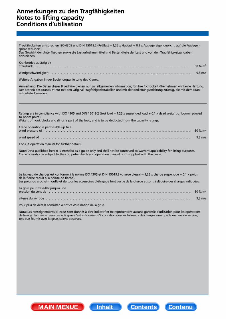
Anmerkungen zu den TragfähigkeitenNotes to lifting capacityConditions d’utilisation
Tragfähigkeiten entsprechen ISO 4305 und DIN 15019.2 (Prüflast = 1,25 x Hublast + 0,1 x Auslegereigengewicht, auf die Ausleger-spitze reduziert).Das Gewicht der Unterflaschen sowie die Lastaufnahmemittel sind Bestandteile der Last und von den Tragfähigkeitsangabenabzuziehen.
Kranbetrieb zulässig bis:Staudruck . . . . . . . . . . . . . . . . . . . . . . . . . . . . . . . . . . . . . . . . . . . . . . . . . . . . . . . . . . . . . . . . . . . . . . . . . . . . . . . . . . . . . . . . . . . . . . . . . . . . . . . . 60 N/m2
Windgeschwindigkeit . . . . . . . . . . . . . . . . . . . . . . . . . . . . . . . . . . . . . . . . . . . . . . . . . . . . . . . . . . . . . . . . . . . . . . . . . . . . . . . . . . . . . . . . . . . . . . 9,8 m/s
Weitere Angaben in der Bedienungsanleitung des Kranes.
Anmerkung: Die Daten dieser Broschüre dienen nur zur allgemeinen Information; für ihre Richtigkeit übernehmen wir keine Haftung.Der Betrieb des Kranes ist nur mit den Original-Tragfähigkeitstabellen und mit der Bedienungsanleitung zulässig, die mit dem Kran mitgeliefert werden.
Ratings are in compliance with ISO 4305 and DIN 15019.2 (test load = 1.25 x suspended load + 0.1 x dead weight of boom reducedto boom point).Weight of hook blocks and slings is part of the load, and is to be deducted from the capacity ratings.
Crane operation is permissible up to awind pressure of . . . . . . . . . . . . . . . . . . . . . . . . . . . . . . . . . . . . . . . . . . . . . . . . . . . . . . . . . . . . . . . . . . . . . . . . . . . . . . . . . . . . . . . . . . . . . . . . . . 60 N/m2
wind speed of . . . . . . . . . . . . . . . . . . . . . . . . . . . . . . . . . . . . . . . . . . . . . . . . . . . . . . . . . . . . . . . . . . . . . . . . . . . . . . . . . . . . . . . . . . . . . . . . . . . . 9.8 m/s
Consult operation manual for further details.
Note: Data published herein is intended as a guide only and shall not be construed to warrant applicability for lifting purposes. Crane operation is subject to the computer charts and operation manual both supplied with the crane.
Le tableau de charges est conforme à la norme ISO 4305 et DIN 15019.2 (charge d’essai = 1,25 x charge suspendue + 0,1 x poidsde la flèche réduit à la pointe de flèche).Les poids du crochet-moufle et de tous les accessoires d’élingage font partie de la charge et sont à déduire des charges indiquées.
La grue peut travailler jusqu’à unepression du vent de . . . . . . . . . . . . . . . . . . . . . . . . . . . . . . . . . . . . . . . . . . . . . . . . . . . . . . . . . . . . . . . . . . . . . . . . . . . . . . . . . . . . . . . . . . . . . . . 60 N/m2
vitesse du vent de . . . . . . . . . . . . . . . . . . . . . . . . . . . . . . . . . . . . . . . . . . . . . . . . . . . . . . . . . . . . . . . . . . . . . . . . . . . . . . . . . . . . . . . . . . . . . . . . . 9,8 m/s
Pour plus de détails consulter la notice d’utilisation de la grue.
Nota: Les renseignements ci-inclus sont donnés à titre indicatif et ne représentent aucune garantie d’utilisation pour les opérationsde levage. La mise en service de la grue n’est autorisée qu’à condition que les tableaux de charges ainsi que le manuel de service,tels que fournis avec la grue, soient observés.
MAIN MENUE Inhalt Contents Contenu
AC 40-1 10/99 03.05.2000 10:58 Uhr Seite 20

ZeichenerklärungKeyLégende
Tragfähigkeiten, abgestützt · Lifting capacities on outriggers · Capacités de levage sur stabilisateurs · 360°
frei auf Rädern · free on wheels · sur pneus
„D“ D
MAIN MENUE Inhalt Contents Contenu
AC 40-1 10/99 03.05.2000 10:58 Uhr Seite 21