Embed Size (px)
Citation preview
1969CAR
SHOPMANUAL
VOLUME ONECHASSIS
EELS and TIRES, SUSPENSION, STEERING, BRAKESCLUTCH and TRANSMISSION, REAR AXLE
FALCON
FAIRLAN 1E
MUSTANG
FORD
THUNDERBIRD
MONTEGO
COUGAR
METEOR
MERCURY
LINCOLNCONTINENTAL
CONTINENTALMARK Ill_
VEHICLE IDENTIFICATION
BRAKES
2
SUSPENSION, STEERING WHEELS AND TIRES
REAR AXLE
4
DRIVE SHAFT AND CLUTCH
MANUAL SHIFT TRANSMISSION
6
AUTOMATIC TRANSMISSION
M FIVE
GROUP INDEX
1969CAR
SHOPMANUAL
VOLUME ONECHASSIS
WHEELS and TIRES, SUSPENSION, STEERING, BRAKES,CLUTCH and TRANSMISSION, REAR AXLE
SERVICE PUBLICATIONS
FIRST PRINTING-NOVEMBER, 1968© 1968 FORD MOTOR COMPANY, DEARBORN, MICHIGAN
SPECIFICATIONS AND SPECIAL SERVICE TOOLSAT END OF EACH GROUP
Copyright © 2006, Forel Publishing Company, LLC, Woodbridge, Virginia
All Rights Reserved. No part of this book may be used or reproduced in any manner
whatsoever without written permission of Forel Publishing Company, LLC. For information write to Forel Publishing Company, LLC, 3999 Peregrine Ridge Ct.,
Woodbridge, VA 22192
1969 Ford Car Shop Manual ISBN: 0-9673211-6-6
EAN: 978-0-9673211-6-5
Forel Publishing Company, LLC 3999 Peregrine Ridge Ct. Woodbridge, VA 22192
Email address: [email protected] Website: http://www.ForelPublishing.com
Disclaimer
Although every effort was made to ensure the accuracy of this book, no representations or warranties of any kind are made concerning the accuracy, completeness or suitability of the information, either expressed or implied. As a result, the information contained within this book should be used as general information only. The author and Forel Publishing Company, LLC shall have neither liability nor responsibility to any person or entity with respect to any loss or damage caused, or alleged to be caused, directly or indirectly by the information contained in this book. Further, the publisher and author are not engaged in rendering legal or other professional services. If legal, mechanical, electrical, or other expert assistance is required, the services of a competent professional should be sought.
FOREWORD Thefive volumes of this shop manual provide theservice-~echnician with completP information for the proper servicing of all the1969 line of Ford Passenger Cars.
The information is grouped accoriing to the type of work being per- formed, such as frequently performed adjustments and repairs, in- vehicle adjustments, major repair, etc. Specifications, maintenance information and recommendedspecial tools are included.
The descriptions and specifications in this manual-were in effect at the time {his manual was approved for printing. Ford Motor Company reserves the right to discontinue models at any time, or changespecifi- cations or design, without noticeand without incurring obligation.
S E R V I C E P U B L I C A T I O N S
5006
August 1997
GENER,AL INFORMATION
Individual carline shop manuals have been combined in one Car Shop Manual divided into five volumes for 1969.
The 1969 Car Shop Manual has been organized into general Groups as i n previous shop manuals. All Groups are listed in the Group index on the first page of each Volume. Groups not contained in a given Volume are listed with a solid gray background. n
To locate the beginning page of any particular Group, first select the Volume containing that Group. Bend the manual until the black mark on the first page of the Group can be seen in line with the Group title on the first page of the Volume.
The first page of each Group lists the material contained in the Group under Part headings and also lists the beginning page of each Part.
I On the beginning page of each .Part, there is a Part index which
lists in detail all information appearing in the Part, the page where the information is given, and the .vehicles to which the information applies.
All pages carry a six-digit number which indicates the Group, Part and Page number.
For Example: Page 03-02-01 indicates Group 3, Part 2, Page 1
Part Indexes will use only the Part and Page referencinumbers. For Examljle: Page 03-02-01 will appear in the Part Index as 02-01.
Each Part will start with Page 01
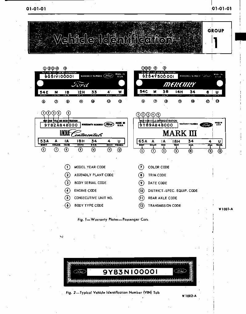
@ MODEL YEAR CODE @ COLOR CODE 1
@ ASSEMBLY PLANT CODE @ TRIM CODE I
@ BODY SERIALCODE @ DATE CODE
@ ENGINE CODE @ DISTRICT-SPEC. EQUIP. CODE I I
@ ' CONSECUTIVE UNIT NO. @ REAR AXLE CODE I
@ BODY TYPE CODE @ TRANSMISSION CODE 8 ' I W 1001-A
Fig. I -Warranty Plates-Passenger Cars !
Fig. 2-Typical Vehicle Identification Number (VIN) Tab
: 0 1 - 0 1 - 0 2 Vehicle Identification 0 1 -01 -02
I
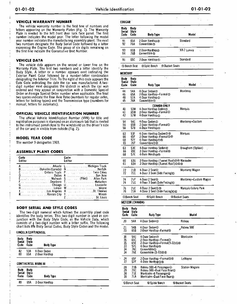
, VEHICLE W A R R A N T Y NUMBER COUGAR The vehic lewarranty number is the .first l ine of numbers and
~ o d y Body ; letters appearing on the Warranty Plates (Fig. 1). The Warranty i Plate i s riveted to the le f t front door lock face panel. The f irst Serial Style
Code Code Body Type Model I number indicates the model year. The letter fol lowing the model
year number indicates the manufacturing assembly plant. 'The next 91 ' 65A 2-Door Hardtop@ Standard two numbers designate the Body Serial Code followed by a letter 92 76A Conver t~ble~ expressing the Engine Code. The group of six digits remaining o n
93 65B 2-Door Hardtop@ XR-7 Luxury .. the first l ine indicate the Consecutive Unit Number. 94 768 Convertible@
VEHICLE D A T A The vehicle data appears on the second or lower l i ne o n the
Warranty Plate. The f irst two numbers and a letter ident i fy the Body Style. A letter or a number appears next indicating the Exterior Paint Color followed by a number-letter combination designating the In ter ior T r im. To the r ight of th is code appears the Date Code indicating the date the car was manufactured. A two- digit number next designates the ,distr ict i n which the car was ordered and may appear i n conjunction wi th a Domestic Special Order or Foreign Special Order'number when applicable. The f inal two spaces indicate the Rear Axle Ratio (numbers for regular axles, letters for locking-types) and the Transmission type (numbers.for manual, letters for automatic).
OFFICIAL VEHICLE IDENTIF ICATION NUMBER The official Vehicle Identification .Number (VIN) for t i t le and
registration purposes i s stamped on an a luminum tab that is riveted to the instrument panel close to the windshield on the driver's side of the car and is visible f rom outside (Fig. 2).
M O D E L YEAR CODE The number 9 designates 1969.
ASSEMBLY P L A N T CODES
Code Code Letter Letter
A,. . . . . . . . . . . . . . . . . . . . . . .Atlanta L. . . . . . . . . . . . . . . ..Michigan Truck B . . . . . . . . . . . . . .Oakville (Canada) N . . . . . . . . . . . . . . . . . . . . . . .Norfolk C.. . . . . . :. . . . . . . . . .Ontario Truck P.. . . . . : . . . . . . . . . . . . .Twin Cities D.. . . . . . . . . . . . . . . . . . . . . . . .Dallas R . . . . . . . . . . . . . . . . . . . . . . San Jose E . . . . . . . . . . . . . . . . . . . . . . . . .Mahwah S . . . . . . . . . . (Pilot).. . Al len Park F... . . . . . . . . . . . . . . . . . . .Dearborn T . . . . . . . . . . . . . . . . . . . . . .Metuchen G . . . . . . . . . . . . . . . . . . . . . . . .Chicago U. . . . . . . . . . . . . . . . . . . . . .Louisville H. . . . . . . . . . . . . . . . . . . . . . . . Lorain W.. . . . . . . . . . . . . . . . . . . . . . .Wayne J.. . . . . . . . . . . . . . . . . . . Los Angeles X . . . . . . . . . . . . . . . . . . . .St. Thomas .K.. . . . . . . . . . . . . . . . . . .Kansas City Y . . . . . . . . . . . . . . . . . . . . . . . .Wixom
Z . . . . . . . . . . . . . . . . . . . . . S t . Louis
91 65C 2.Door Hardtop@ Standard
@Bench Seat @Split Bench @Bucket Seats
MERCURY
Body Body Serial Style Code Code Body Type Model
44 54A &Door Sedan@ Monterey 46 65A 2-Door Hardtop-Formal@ 48 57A 4.Door Hardtop@ 45 76A Convertible@
CANADA ONLY. 40 53M 4-Door Hardtop Sedan@ Marquis 41 .65M 2-Door Hardtop-FormalO 42 57M 4-Door Hardtop@ - 54 54C 4-Door Sedan@ Monterey-Custom 56 658 2-Door Hardtop-Formal@ 58 578 4.Door Hardtop@
63 53F 4.Door ~ a r d t o ~ sedan@@ Marquis 66 65F 2.Door Hardtop-Formal@@ 68 57F 4-Door Hardtop@@ 65 76F Convertible@@ 63 53C 4-Door Hardtop Sedan@ Brougham (Option) 66 65C 2-Door Hardtop-FormalO 68 57C 4-Door Hardtop@
60 63G 2-Door Hardtop (Tunnel Roof)@@ Marauder 61 63H 2-Door Hardtop (Tunnel Roof)@@@
72 718 4-Door 2 Seat@ ,Monterey Wagon 72 71C &Door 3 Seat (Side Facing@
74 71F 4-Door2 Seat@ Monterey-Custom Wagon 74 71G 4-Door 3 Seat (Side Facingb
76 71E 4-Door L.Seat@@ Marquis Colony Park 76 71A 4-Door 3 Seat (Side Facing)@@
@Bench Seat @Split Bench @Bucket Seats
METEOR (CANADA)
B O D Y SERIAL A N D STYLE CODES Bodv Bodv Serial Styk , The two-d ig i t numeral which follows the assembly p lant code
identifies the body series. This two-d ig i t number i s used i n con- Code Code Body Type Model junction wi th the Body Style Code, i n the Vehicle Data, which 20 54A 4-Door Sedan@ Rideau consists of a two-d ig i t number wi th a letter suffix. The fol lowing - c h a r t lists tti'e Body Serial Codes, Body Style Codes and the model. 21 548 Sedan@ .Rideau 500
1 LINCOLN CONTINENTAL 23 658 2-Door Hardtop-FormalO
Body Body ' Serial Style
Code Code Body Type
82 53A 4.DoorSedan 80 65A 2-Door Hardtop
I CONTINENTAL MARK Ill '
Body Body Serial Style Code Code Body Type
30 54C &Do01 Sedan@ Montcalm 35 65C 2-Door Hardtop-Formal13 35 65E 2-Door Hardtop-Formal(5-33)W 33 57C 4-Door Hardtop@ 34 76C Convertible@ 34 76E Convertible (S-33)@@
24 65F 2.Door Hardtop-Formal@@ LeMoyne 27 57F 4-Door Hardtop@@
28 718 Rideau 5 0 0 6 passenger6 Station Wagons 29 71C Rideau 500-Dual Face Rear@ 38 71E Montcalmd Passenger@ 39 71A Montcalm4ual Face Rear@
@Bench Seat OSplite Bench @Bucket Seats
I I
0 1 - 0 1 - 0 3 Vehicle Identification I
0 1-01 - 0 3
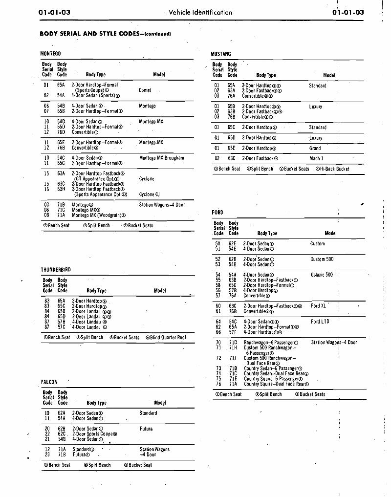
B O D Y SERIAL A N D STYLE CODES-(continued) . .
I
MONTEGO . .
Body Body Serial Style Code Code Body Type Model
01 65A 2-Door Hardtop4ormal (Sports Coupe)@ Comet
02 54A &Door Sedan(Sports)@
06 548 4-Door Sedan@ Montego. 07 658 2-Door Hard top4ormalO
10 54D 4 -Doo rSedan~ Montego MX 11 65D 2-Door Hardtop-Formal@ 12 76D Convert~ble@
11 65E 2-Door Hardtop-Formal@ Montego MX 12 768 Convertible@
10 54C &Door Sedan@ Montego MX Brougham 11 65C 2-Door Hardtop4ormalO
15 63A 2-Door Hardtop Fastback@' (GT Ap earance Opt.@) Cyclone
15 63C 2-Door la rd top Fastback@ 16 63H ?.Door Hardtop Fastback@
(Sports Appearance Opt.@) - Cyclone CJ
03 718 Montego@ Station Wagons4 Door 08 71C MontegoMXO 08 71A Montego MX (Woodgrain)@
@Bench Seat @Split Bench . . @Bucket Seats
Body Body Serial Style Code Code Body Type Model
83 65A 2-Door Hardtop@ 83 65C 2-Door Hardtop@ 84 658 2-Door Landau @@ 84 65D 2-Door Landau @@ 87 578 Landau @ 87 57C 4-D001 Landau @
@Bench Seat @Split Bench @Bucket Seats @Blind Quarter Roof
FALCON '
Body Body Serial Style Code Code Body Type Model
10 . 62A 2-Door Sedan@ Standard 11 . 54A 4-Door Sedan@
20 628 2-Door Sedan@ Futura 22 62C 2-Door Sports Coupe6 21 548 4-Door Sedan@
MUSTANG
Body Body . I
' Serial Style I
Code Code Body Type Model ' 01 65A 2-Door Hardtop@@ Standard 02 63A FDoor Fastback@@ 03 76A Convertible@@
01 658 2-Door Hardtop@@ Luxury 02 638 24001 Fastback@@ 03 768 Convertible@@
01 65C 2-Door Hardtop@ Standard
01 65D 2-Door Hardtop@ luxury '
01 65E 2-Door Hardtop@ Grand
02 63C 2-Door Fastback@ Mach 1
@Bench Seat @Split Bench OBucket Seats @Hi-Back Bucket
FORD
Body Body Serial Style I
Code Code Body Type Model
50 62E 2-Door Sedan@ Custom 51 54E 4-Door Sedan@
52 628 2 -~oo ;~edan@ Custom 500 , 53 548 Sedan@
-
54 54A 4-Door Sedan@ Galaxie 500 1 55 638 2.Door Hardtop4astbackO I
58 65C 2-Door Hardtop-Formal@ 1 56 578 4.Door Hardtop@ I 57. 76A Convertible@
60 63C 2-Door Hardtop4astbackOO Ford XL ' I 61 766 Convertible@@
64 54C 4-Door Sedan@@ Ford LTD 62 65A 2-Door Hardtop-Formal@@ 66 57F &Door Hardtop@@
RanchwagondPassenger@ Station wagons4 Door Custom 500 Ranchwagon- !
6 Passenger@ I
Custom 500 Ranchwagon- Dual Face Rear@
Country Sedan4 Passenger@ Country Sedan-Dual Face Rear@ Country Squ i r ed Passenger@ Country Squire-Dual Face Rear@
@Bench Seat @Split Bench OBucket Seats
12 71A Standard@ ' Station Wagons 23 718 Futuraa 4 Door
@Bench Seat @Split Bench @Bucket Seat
01-01-04 Vehicle Identification 01'-01-04
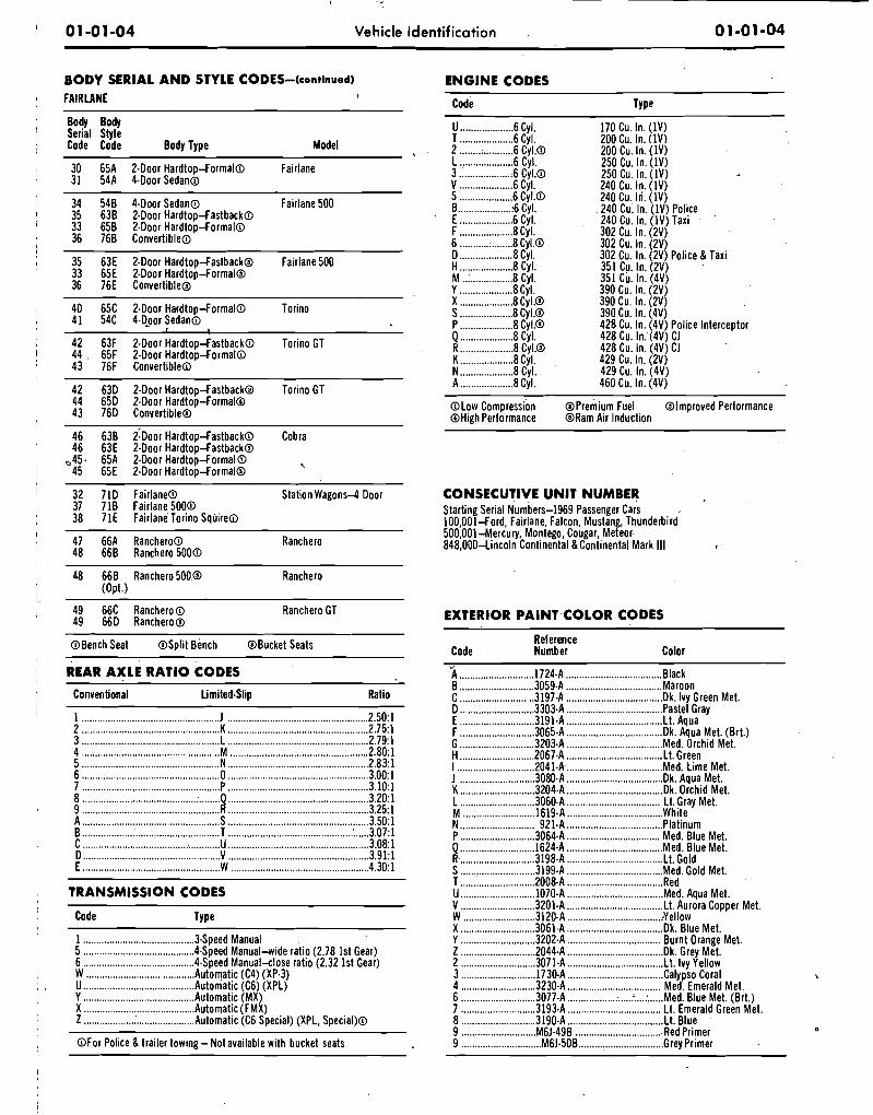
B O D Y SERIAL A N D STYLE CODES-(conttnued) E~GINE CODES FAIRLANE Code Type
Body Body Serial Style Code Code Body Type Model
30 65A 2-Door Hardtopdormal@ Fairlane 31 54A 4-D001 Sedan@
34 548 4-Door Sedan@ Fairlane 500 35 638 2-Door Hardtop-Fastback@ 33 658 2.Door HardtopdormalO 36 768 Convertible@
35 63E 2-Door Hardtopdastback@ Fairlane 500 33 65E 2-Door Hardtop-Formal@ 36 76E Convertible@
40 65C 24001 Hardtop-Formal@ Torino 41 54C 44-001 Sedan@
42 63F 2-Door HardtopdastbackO Torino GT 44 . 65F 2-Door HardtopdormalO 43 76F Convertible@
42 63D 2-Door HardtopqastbackQ Torino GT 44 65D 2.Door Hardtop-Formal@ 43 76D Convertible@
46 638 2 :~oo~a rd topdas tback@ Cobra 46 63E 2-Door HardtopdastbackO
-45. 65A 2.Door Hard topdormalO 45 65E 2.Door HardtopdormalO
-.
U .................... 6 Cyl. T .................... 6 Cyl. 2 .................... 6 Cyl.0 L .................... 6 Cyl. 3 ................... :6 Cyl.0 V .................... 6 Cyl. 5 .................... 6 Cyl.0 B .................... :6 Cyl. E .................... 6 Cyl. F .................... 8 Cyl. 6 .................... 8 Cyl.0 D .................... 8Cyl. H .................... 8 Cyl. M ................... 8 Cyl. Y .................... 8Cyl. X .................... 8 Cyl.0 .................... S 8 Cyl.@
P .................... 8 Cyl.0 Q .................... 8 Cyl. R .................... 8 Cyl.@ K .................... 8 Cyl. N .................... 8 Cyl. A .................... 8 Cyl.
@Low Compression @High Performance
170 Cu. In. (1V) 200 Cu. In. (1V) 200 Cu. In. (1V) 250 CU. ~ n . i l Y j 250 Cu. In. (1V) 240 Cu. In. (1V) 240 Cu. In. (1V) 240 Cu: In. (1V) Police 240 Cu. In. (lV) Taxi 302 Cu. In. (2V) 302 Cu. In. (2V) 302 Cu. In. (2V) Police & Taxi 351 Cu. In. (2V) 351 Cu. In. (4V) 390 Cu. In. (2V) 390 Cu. In. (2V) 390 Cu. In. (4V)
@Premium Fuel @Improved Performance @Ram Air Induction
32 71D Fairlane@ Station Wagons4 Door CONSECUTIVE U N I T NUMBER 37 718 Fairlane 5 0 0 0 Starting Serial ~umbers-1969 Passenger Cars 38 71E Fairlane'Torino SqliireO 100,00ldord, Fairlane. Falcon, Mustang, Thunderbird
47 66A Ranchero@ 500,001-Mercury, Montego, Cougar, Meteor-
Ranchero 48 66B Ranchero 5 0 0 0
848,0004incoln Continental &Continental Mark Ill
48 66B Ranchero 500.a Ranchero (Opt.)
49 66C Ranchero@ Ranchero GT 49 66D Ranchero@
@Bench Seat @Split Bench @Bucket Seats
REAR AXLE RATIO CODES
Conventional Limited-Slip Ratio
T R A N S M I S S I O N CODES
Code Type
1 ......................................... S p e d Manual 5 .................................... 4Speed Manual-wide ratio (2.78 1st Gear) 6 ...................................... S p e d Manual-close ratlo (2.32 1st Gear) W ......................................... A t o m a t c (C4) (XP.3) U .................................... Automatic (C6) (XPL) Y .......................................... Automatic (MX) X ...................................... Automatic (FMX) Z .......................................... Automatic (C6 Special) (XPL, Special)@
@For Police &trailer to,wing -Not available with bucket seats
EXTERIOR P A I N T C O L O R CODES
Reference Code Number Color -
................................. ............................ 2 1724-A Black B ............................ 3059-A .................................... Maroon
............................ .................................... C 3197.A Dk. Ivy Green Met. D ............................ 3303-A .................................... Pastel Gray E ............................ 3191-A .................................... Lt. Aqua F .................. : ......... 3065-A .................................... Dk. Aqua Met. (Brt.) G .......................... .:3203-A ................................... Med. Orchid Met. H ............................ 2067-A .................................... Lt. Green I ............................. 20414 .................................... Med. Lime Met.
.................................... ............................ J 3080-A Dk. Aqua Met. K ............................ 3204.A .................................... Dk. Orchid Met. L ............................ 3060-A ................................... Lt. Gray Met.
..................................... ........................... M 1619-A White N ............................ 921.A .................................... Platinum P ............................ 3064.A ................................... Med. Blue Met. Q ........................... J624.A .................................... Med. Blue Met. R- ............................ 3198-A .................................... Lt. Gold S ............................ 3199-A .................................... Med. Gold Met. T ............................ 2008.A .................................... Red U ............................ 1070-A .................................... Med. Aqua Met. V ............................ 3201-A .................................... Lt. Aurora Copper Met. W ........................... 3120.A ................................... :Yellow X ............................ 3061-A .................................... Dk. Blue Met. Y ............................ 3202.A ................................... Burnt Orange Met. Z ............................ 2044-A .................... .: .............. Dk. Grey Met. 2 ............................ 3071-A .................................... Lt. Ivy Yellow 3 ............................ 1730-A .................................... Calypso Coral 4 ............................ 3230-A ................................... Med. Emerald Met. 6 ............................ 3077-A .................. .: .... T .... : ..... Med. Blue Met. (Brt.) 7 ............................ 3193-A ................................... Lt. Emerald Green Met. 8 ............................ 3190-A .................................... Lt. Blue 9 ............................ M6J.49B ................................. Red Primer 9 .............................. M6J.50B ,,, ............................ Grey Primer
I I 01-01-05 Vehicle Identification 01-01-05 1
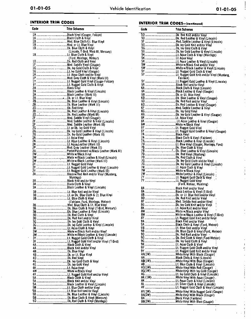
. INTERIOR T R I M CODES INTERIOR TR IM CODES-(cont~nued)
Code Trim Schemes Code Trim Schemes
1A ........................................ Back Vinyl (Cougar, Falcon) 1A ................. : ...................... Back Cloth &Vinyl 10 ........................................ M e . Blue ClothILt. Blue Vinyl 1 0 ........................................ M e . or Lt:Blue Vinyl 10 ........................................ 0 . Blue Cloth &Vinyl
(Lincoln, T-Bird, Mark Ill, Mercury) 10 ........................................ Lt. Bluecloth & Vinyl
(Ford, Montego, Meteor) 1 0 ........................................ 0 . Red Cloth and Vinyl 1F ........................................ M e . Saddle Vinyl (Cougar) 1G ........................................ 0 . Ivy Gold Cloth &Vinyl 1G ........................................ Lt. Ivy Gold Vinyl (Cougar) 1K ........................................ Lt. Aqua Cloth andlor Vinyl 1P ........................................ G r e y Cloth &Vinyl (Mark Ill) 1Y ........................................ Lt. Nugget Gold Vinyl (Cougar-Falcon) 1Y ........................................ Lt. Nugget Gold Cloth & Vinyl 2A ........................................ Back Vinyl 2A ........................................ Back Leather & Vinyl (Lincoln) 2A ........................................ Back Leather (Mark Ill)
................................... .... 28 0 . or Lt: Blue Vinyl . 28 .................................... . . Blue Leather & Vinyl (Lincoln) 28 ...................................... 0 . Blue Leather (Mark I l l ) 20 ........................................ Dk. Red Vinyl 20 ........................................ 0 . Red Leather & Vinyl (Lincoln) 20 ... : .................................... 0 , Red Leather (Mark Ill) 2F ........................................ M e . Saddle Vinyl'(Cougar) 2F ........................................ S a d d l e Leather & Vinyl (Lincoln) 2F ........................................ M e . Saddle Leather (Mark I l l ) 2G ........................................ L o r Dk. Ivy Gold Vinyl 26 ........................................ 0 . Ivy Gold Leather & Vinyl (Lincoln) 2G ........................................ 0 . Ivy Gold Leather (Mark Il l) 2K ........................................ A q u a Vinyl 2K ........................................ Lt. Aqua Leather & Vinyl \Lincoln) 2K ........................................ Lt. AqualLeather (Mark II ) 2P ........................................ G r e y Leather (Mark I l l ) 2U ............ : ........................... Pastel Parchment wBlack Leather (Mark I l l ) 2W ........... ! ........................... White w1Black Vinyl 2W ....................................... White w/Black Leather & Vinyl (Lincoln) 2W .............................. : ........ WhitewIBlack Leather (Mark I l l ) 2Y ........................................ Lt. Nugget Gold Vinyl 2Y ..: ..................................... L t Nugget Gold Leather & Vinyl (Lincoln) 2Y ........................................ Lt. Nugget Gold,Leather (Mark I l l ) 3A ........................................ Back w/Red K n ~ t and/or Vinyl (Mustang, . .
Montego) 3A ........................................ Back K n ~ t andlor Vinyl 3A ........................................ Back Cloth &Vlnyl 3A ..................................... Back Leather & Vinyl (Lincoln) 38 ........................................ Lt. Blue Knit andlor Vinyl 38 ........................................ L t or Dk. Blue Cloth & Lt. Blue Vinyl
........................................ 38 Lt. Blue Cloth &Vinyl (Fairlane, Ford, Montego, Meteor)
........................................ 38 M e . Blue Cloth & Lt. Blue V~nyl
........................................ 38 0 . Blue'Cloth & Vin I (T Bird, Mercury) 38 ........................................ 0 . Blue Leather & i n y l i ~ i n c o l n ) 30 ........................................ 0 . Red Cloth & Vinyl 30 ........................................ 0 . Red Knit andlor Vinyl 36 ........................................ 0 . Ivy Gold Cloth &Vinyl 3G ........................................ 0 . Ivy Gold Leather & Vinyl (Lincoln) 3K ........................................ L t Aqua Cloth & Vinyl 3W ....................................... White w/Black Knit and/or Vinyl 3W ....................................... White w/Black Leather & Vinyl (Lincoln) 3Y ........................................ Lt. Nugget Gold Cloth &Vinyl 3Y ....................................... L . Nu et Gold K n ~ t andlor Vinyl (T-Bird) 4A ........................................ Black fo th .& Vinyl 4A ........................................ Back Knit andlor Vinyl 48 ........................................ 0 . Blue Vinyl 48 ........................................ 0 . or Lt. Blue Vinyl 40 ........................................ 0 . Red Vin I 4G ........................................ k . Ivy Gol (r Cloth & Vinyl 46 ........................................ 0 . Ivy Gold Vinyl 4K ....................................... L t Aqua Vinyl 4W ....................................... White wl l lack Vinyl 4Y .......................... : ............. Lt. Nu et Gold Knit andlor Vinyl 5A ...................................... Back &k th &Vinyl 5A ........................................ Back Knit andlor Vinyl 5A ........................................ Back Leather & V~nyl (Lincoln) 58 ........................................ Lt. Blue Cloth andlor Vin I 5 0 ...................................... . . . B l u e Knit andlor Vin r 50 ........................................ 0 . Blue Leather & viny/(Lincoln) 5 0 ........................................ 0 . Blue Cloth & Vinyl (Mercury) 5 0 ........................................ 0 . Red Cloth & Vinvl (Monteno)
- 5 0 ...................................... 0 . Red Knit and/or Vinyl 1 50 ....................................... 0 . Red Leather & Vinyl (Lincoln) 5F ........................................ M e . Saddle Leather & Vinyl (Lincoln) 56 ........................................ 0 . Ivy Gold Knit andlor Vinyl 5G ........................................ 0 . Ivy Gold Cloth & Vin I 5G ........................................ 0 . Ivy Gold Leather & dny l (Lincoln) 5K ........................................ A q u a Cloth & Vinyl (Montego) 5K ........................................ Lt. Aqua Vinyl 5K ........................................ L t Aqua Leather & Vin I (Lincoln) 5W ...................................... W h e wBlack K n ~ t an d /or Vinyl 5W ....................................... Whde w1BIack Leather & Vinyl (Lincoln) 5Y ....................................... Lt. Nugget Gold Cloth & Vinyl 5Y ........................................ Lt. Nugget Gold Knit andlor Vinyl (Mustang,
Fairlane) 5Y ........................................ N u et Gold Leather & Vinyl (Lincoln) 6 1 ........................................ Black t i ! andlor Vinyl 6A ........................................ B lack l o th & Vin I (Lincoln) 6 1 ........................................ Black Leathy & d n Y l (Cougar) 60 ........................................ 0 . or Lt. Blue Vinyl 6 0 ........................................ 0 . Blue Leather & Vinyl (Cougar) 6 0 ........................................ 0 . Red Knit andlor Vinyl . . 6 0 ........................................ 0 . Red Leather & Vinyl (Cougar) 6F ........................................ M e . Saddle Leather & Vinyl 6G ........................................ 0 . Ivy Gold Vinyl 6G ........................................ 0 . Ivy Gold Leather & Vinyl (Cougar) 6K ........................................ L . Aqua Vinyl 6K ......................................... A q u a Leathy & Vinyl (Cougar) 6W ....................................... White wBlack Vinyl 6Y ................................... :...Lt. Nugget Gold Vinyl 6Y ......................................... L t Nu get Gold Leather & Vinyl (Cougar) 7A ........................................ Back k n y l 7A .................. : ..................... Back Cloth &Vinyl (Fairlane) 7A ........................................ Back Leather & V~nyl (L~ncoln) 70 ........................................ Lt. Blue Vinyl (Cougar, Montego, Ford) 78 ........................................ 0 . Blue Cloth & Vin I 78 ................................ X.."... 0 . Blue Leather & i n y \ (Lincoln) 70 ........................................ 0 . Red Vinyl (Mustang) 7 0 ........................................ 0 . Red Cloth & Vinyl 7G ...................................... . . . Ivy Gold Cloth andlor Vinyl 1 7G ........................................ 0 . Ivy Gold Leather & Vinyl (Lincoln) 7K ........................................ L . Aqua Cloth &Vinyl 7W ....................................... White w1Black Vinyl 7W ....................................... White Leather & V~nyl Lincoln) : 7Y ........................................ L t ~ u g g e t Gold Cloth*k Vinyl 7Y ........................................ Lt. Nugget Gold Vinyl
(Ford, Meteor, Mustang) 8A ........................................ Back Knit andlor Vinyl 8'A ........................................ Back Leather & Vinyl (T-Bird) 88 ........................................ 0 . or Lt. Blue Knit andlor Vinyl 80 ....................................... 0 . Red Knit andlor V~nyl 1
8F ........................................ M e . Saddle Knit andlor Vinyl : 8G ...................................... . . . Ivy Gold Knit andlor Vinyl 8K ........................................ L Aqua Knit andlor Vinyl . 8W ....................................... White w/Black andlor Vin I, 8W ....................................... White w1Black Leather & b~ny! (T-Bird) 8Y ..................................... ; . . Nugget Gold Knit and lorv~ny l 9A ........................................ Back Knit andlor Vin I 9 1 ........................................ Black Cloth &Vinyl (told, ~ete;r) 9 0 .................................. : ..... L t Blue Knit and/or Vin I 9 8 ....................................... Ok. Blue I t & Vinyl ( o r Meleor) 90 ........................................ 0 . Red K n ~ t andlor Vin I . 1 90 ................... : .................... 0 . Red Cloth &Vinyl ( { o l d - ~ e t ~ r ) 9G ........................................ 0 . Ivy Gold Cloth & Vinyl 9K ........................................ Lt. Aqua Cloth & Vin I i 9Y ....................................... .Lt . Nugget Gold clot% andlor ~ i " ' I
........................................ 9Y Lt. N u s e t Gold Knit andlor v iny l AA(1W) ................................ Wh~teVlnyl With Black (Cougar) AA ........................................ Back Cloth & Vin I (Lincoln)
................................ AB(1W) White Vin I With glue (Cygar) AB ..... , .................................. Lt. Blue Both & Vinyl (Lmcoln) AD(1W) ................................ Whitevinyl With Red (Cou ar) i AG(1W) ........... : .................... W h e n I With Iv Gold (iougar) AG ........................................ L t Ivy ~ o r d Cloth %vinyl (Lincoln) AK (1W) ............................... White Vin I With Aqua (Cougar) I
AK ........................... L .......... Lt. Aqua 40 th & Vinyl (Lincoln) AL ...................... : ................. L t Silver Cloth &Vinyl (Lincoln) AY ........................................ L t Nugget Gold Cloth &Vinyl (Lincoln) AY(1W) ................................ Whi eVinyl With Nu et Gold (Cougar)
.......................... BA(2W) Whi~eViny With 01% (Cougar) BA ........................................ Back Vlnyl (Fairlane)
................................ - BB(2W) Wh~teV~ny l With Blue (Cougar)
I
Vehicle Identification
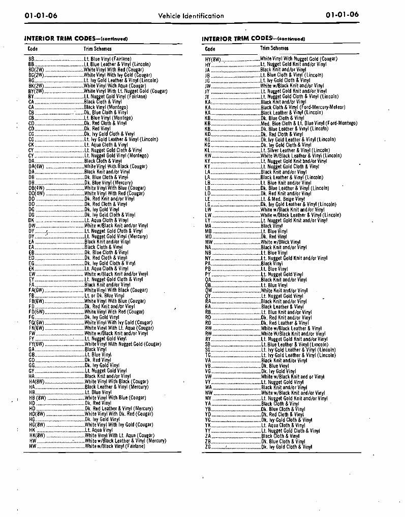
INTERIOR T R l M CODES-(continued)
Code Trim Schemes
BB ........................................ Lt. Blue Vinyl (Fairlane) BB ........................................ Lt. Blue Leather & Vinyl (Lincoln) BD(2W) ............................. ;.Whitevinyl With Red (Cou ar) BG(2W) ................................ White Vinyl With Ivy Gold (tougar) BG ........................................ Lt. Ivy Gold Leather & Vinyl (Lincoln) BK(2W) ................................ White Vlnyl With Aqua (Cougar) BY(2W) ................................ Whitevinyl With Lt. Nu et Gold (Cougar) BY ..................................... L t Nu get Gold Vinyl (&lane) CA ........................................ Back !loth & Vinyl CA ........................................ Back Vin I (Montego)
....... CB ................................ : Dk. Blue b o t h &Vinyl CB ........................................ L t Blue Vlnyl (Montego) CD ...................................... k . Red Cloth & Vinyl CD ........................................ k . Red Vinyl CG ....................................... k Ivy Gold Cloth & Vinyl CG ........................................ Lt. Ivy Gold Leather & Vlnyl (Lincoln) CK ........................................ Lt. Aqua Cloth &Vinyl CY ........................................ Lt. Nugget Gold Cloth &Vinyl CY ........................................ Lt. Nu get Gold Vinyl (Montego) DA ..................................... Back [loth &Vinyl DA(4W) ............................... Whitevinyl With Black (Cougar) DA ........................................ Black Knit and/or Vinyl DB ....................................... Dk. Blue Cloth & Vinyl DB ....................................... k Blue Vlnyl (Mercury)
............................... DB(4W) White Vinyl With Blue (Cougar) DD(4W) ............................... White Vin I With Red (Cougar) DD ..................................... ,Slk Red Jnit and/or Vinyl DD ....................................... Dk. Red Cloth & Vinyl DG ....................................... Dk. Ivy Gold Vinyl DG ....................................... Dk. Ivy Gold Cloth &Vinyl DK ....................................... L t Aqua Cloth &Vinyl DW ....................................... White w/Black Knit and/or Vinyl DY ......... r ............................. L . Nugget Gold Cloth & Vinyl DY ........ ................................ L t Nugget Gold Vlnyl (Mercury) EA ........................................ Back Knit and/or Viqyl EA ........................................ Back Cloth &Vinyl EB ...................................... k Blue Cloth &Vinyl ED ........................................ k . Red Cloth &Vinyl EG ........................................ k Ivy Gold Cloth & Vinyl EK ........................................ L t Aqua Cloth & Vinyl EW ...................................... White w/Black Knit and/or Vinyl EY ........................................ Lt. Nugget Gold Cloth & Vinyl FA ....................................... Back Knit and/or Vin I FA(6W) ................................ Whitevinyl With Mac[ (Cougar) FB ........................................ Lt. or Dk. Blue Vinyl FB(6W) ................................ White Vlnyl W~ th Blue (Cougar) FD ........................................ k Red Knit andlor Vinyl FD(6W) ................................ Whitevinyl With Red (Cougar) FG ...................................... k Ivy Gold Vinyl FG(6W) ................................ Whitevinyl With Ivy Gold (Cougar) FK(6W) ............................... White Vin I With Lt Aqua (Cougar) FW ....................................... White wdlack ~ni t 'and/or Vinyl FY .............................. : ......... L t Nugget Gold Vinyl FY(6W) ................................ Whitevinyl With Nugget Gold (Cougar) GA ........................................ Back Vinyl GB ........................................ L t Blue Vinyl GD ........................................ k Red Vin I dY GG ........................................ k Ivy Gol Vinyl GY ........................................ Lt. Nugget Gold Vinyl HA ........................................ Black Knit and/or Vinyl HA(8W) ................................ White Vinyl With Black (Cougar) HA ...................................... Black Leather & Vinyl (Mercury) HB ....................................... L t Blue Vinyl HB (8W) .............................. Whitevinyl With Blue (Cougar) HD ....................................... D k Red Vinyl HD ....................................... Dk. Red Leather & Vinyl (Mercury)
............................... HD(8W) White Vinyl With Dk. Red (Cougar) HG ...................................... k Ivy Gold Vinyl HG(8W) ............................... Whitevinyl With Ivy Gold (Cougar) HK ....................................... L t Aqua Vinyl HK(8W) ............................... White Vin I With Lt. Aqua (Cougar) HW ............................. : ........ White w d a c k Leather & Vinyl (Mercury) HW ....................................... White w/Black Vinyl (Fairlane)
INTERIOR TRlM CODESi-(continued)
Code Trim Schemes
H Y ( ~ W ) ................................ White Vinyl With Nugget Gold (Cougar) HY ........................................ Lt. Nugget Gold Knlt andlor Vinyl JA ........................................ a Knit and/or Vinyl JB ....................................... L Blue Cloth & Vinyl (Lincoln) JG ........................................ L . IVY Gold Cloth& Vinyl JW ........................................ White w/Black Knit and/or Vinyl JY ........................................ Lt. Nugget Gold Knit andlor Vinyl JY ........................................ t Nugget Gold Cloth & Vinyl (Lincoln) KA, ....................................... Back K n ~ t and/or Vln I KA ........................................ Black Cloth & Vin I (?ord-~ercury-~eteor) J. KA ........................................ Back Leather & ~ n y l (Lincoln)
........................................ KB k . Blue Cloth & Vinyl
........................................ KB M e Blue Cloth & Lt. Blue Vinyl (Ford-Montego)
........................................ KB k . Blue Leather & Vinyl (Lincoln) KD ........................................ k Red Cloth &Vinyl
........................................ KG Dk. Ivy Gold Leather & Vinyl (Lincoln) KG ....................................... k Ivy Gold Cloth & Vinyl
........................................ KL Lt. Silver Leather & Vinyl (Lincoln) ....................................... KW White W/Black Leather & Vinyl (Lincoln)
KY ............................. ; .......... Lt. Nugget Gold Knit and/or Vinyl ........................................ KY L t Nugget Gold Cloth & Vinyl
LA ........................................ Back Knit and/or Vinyl LA ........................................ Back Leather & Vinyl (Lincoln)
........................................ LB L t Blue Knit and/or Vinyl
........................................ LB k Blue Leather & Vinyl (Lincoln) LD ....................................... D k Red Knit and/or Vinyl
....................................... LE Lt. & Med. Beige Vinyl
...... ................................. LG : k Ivy Gold Leather & Vinyl (Lincoln) ..................................... LW White w/Black Knit and/or Vinyl
. LW ....................................... White w/Black Leather & Vinyl (Lincoln) ........................................ LY Lt. Nugget Gold Knit and/or Vinyl
. MA ....................................... Black Vlnyl MB ....................................... Lt. Blue Vinyl MD ....................................... Dk. Red Vlnyl MW ...................................... White wWlack Vin I
........................................ NA Black Knit and/or &inyl ....................................... NB Lt. Blue Vin I ..................................... NY L t Nuqe t (told Knit andlor Vinyl
PA ........................................ Black V~nyl PB ........................................ L t Blue Vin I
........................................ PY Lt. Nugget Jold Vinyl QA ........................................ Back Knit and/or Vinyl
Lt. Blue Vinyl ...................................... White Knit and/or Vinyl
........................................ QY Lt. Nugget Gold Vinyl RA ........................................ Back Knit and/or Vinyl RA ....................................... Back Leather & Vinyl RB..: .................................... L t Blue Knit and/or Vinyl RD ....................................... D k Red Knit and/or Vinyl RD ....................................... Dk. Red Leather & Vinyl RW ....................................... White w/Black Leather & Vinyl RW ....................................... White W/Black Knit and/or Vinyl RY ........................................ Lt. Nugget Gold Knit andlor Vlnyl SB ........................................ Lt. Blue Leather & Vinyl(Linco!n) SG ........................................ Lt. IvyGold Leather & V~nyl (L~ncoln) TG ........................................ Lt. Ivy Gold Leather & Vinyl (Lincoln) VA ........................................ Back K n ~ t and/or Vinyl VB ........................................ Dk. Blue Vinyl VG ........................................ k . Ivy Gold Vinyl VW ..................................... White w/Black Knit and or Vinyl VY ..................................... . . . . Nugget Gold Vinyl WA ....................................... Black Knit and/or Vinyl WW ...................................... White w/Black Knit,and/or Vinyl WY ....................................... Lt. Nu get Gold K n ~ t and/or Vinyl YA ................................. .......Back !loth &Vinyl YB ........................................ k . Blue Cloth &Vinyl YD ........................................ k . Red Cloth & Vinyl YG ............ ; ........................... k . Ivy Gold Cloth & Vinyl YK ........................................ Lt. Aqua Cloth &Vinyl YY ........................................ Lt. Nu get Gold Cloth & Vinyl ZA ..................................... Black !loth & Vinyl ZB ........................................ k Blue Cloth & Vinyl ZG ........... ! ............................ k . Ivy Gold Cloth & Vinyl
Vehicle Identification
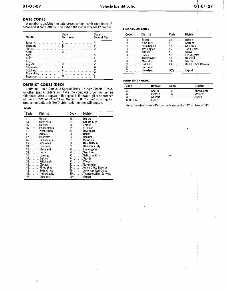
DATE CODES A number s ign i fy ing t he date precedes t h e mon th code let ter. A
second-year code le t ter w i l l be used i f t he mode l exceeds 12 months.
Code Code Month F i rs t Year Second Year
January.. . . . . . . . . . . . . . . . . . A , . . . . . . . . . . . . . . . . . . . . . N February.. . . . . . . . . . . . . . . . . .B . . . . . . . . . . . . . . . . . . . . . . . P March.. . . . . . . . . . . . . . . . . . . . . C.. . . . . . . . . . . . . . . . . . . . . . Q April.. . . . . . . . . . . . . . . . . . . . . . D. .... . . . . . . . . . . . . . . R May.. . . . . . . . . . . . . . . . . . . . . . . E.. . . . . . . . . . . . . . . . . . . . . . S June.. . . . . . . . . . . . . . . . . . . . . . F.. . . . . . . . . . . . . . . . . . . . .T July. . . . . . . . . . . . . . . . . . . . . : r :G.. . . . . . . . . . . . . . . . . . . . . . U August.. . . . . . . . . . . . . . . . . . . . H . . . . . . . . . . . . . . . . . . . . . . . V September.. . . . . . . . . . . . . . . . . J . . . . . . . . . . . . . . . . . . . . . . . . W October.-. . . . . . . . . . . . . . . . . . . K . . . . . . . . . . . . . . . . . . . . . . . X November.. . . . . . . . . . . . . . . . . L . . . . . . . . . . . . . . . . . . . . . . .Y December.. . . . . . . . . . . . . . . . . M . . . . . . . . . . . . . . . . . . . . . . . Z
DISTRICT CODES (DSO) Un i t s bu i l t o n a Domest ic Special Order, Foreign Spec ia l Order,
o r o ther special o rders w i l l have t he comple te order number i n t h i s space. Also t o appear i n t h i s space i s t he two -d ig i t code number o f t he Dis t r ic t wh ich ordered t he un i t . I f t h e u n i t i s a regular product ion un i t , on l y t h e Dis t r ic t code number w i l l appear.
F O R D
Code Dis t r ic t Code Dis t r ic t
. . . . . . 11.. Bodon 13 . . . . . . . .New York
. . . . . . 15. .Newark
. . . . 16. :. .Philadelphia
. . . . . . 17. .Washington
. . . . . . 21. .Atlanta
. . . . . . 22. .Charlotte 24. . . . . . . .Jacksonville
. . . . . . 25. .Richmond
. . . . . . 28. .Louisville 32. . . . . . . .Cleveland 33.. . . . . . .Detroit
41. . . . . . . .Chicago- 43.. . . . . . . Milwaukee 44.. . . . . . .Twin Cities
51.. . . . . . .Denver . . . . . . 53 . . .Kansas City
54. . . . . . . .Omaha 55. . . . . . . .St. Louis 56.. . . . . . . Davenoort
. . . . . . 61. .Dallas' 62. . . . . . . .Houston
. . . . . 63.. .Memphis . . . . . . 64. .New Orleans
65. . . . . . ..Oklahoma City 71. . . . . . . . Los Angeles 72.. . . . . . .San Jose 73. . . . . . . .Salt Lake City 74. . . . . . . .Seattle 75. . . . . . . .Phoenix
. . . . . . 83 .Government 84. . . . . . . . Home Off ice Reserve 85. . . . . . . .American Red Cross 89.. . . . . . .Transportation Services 90's . . . . . .Export
LINCOLN-MERCURY
Code Distr ict Code Distr ict
11. . . . . . . . . .Boston 15.. . . . . . . . .New York 16. . . . . . . . . .Philadelphia 17.. . . . . . . . .Washington 21. . . . . . . . . .Altanta 22.. . . . . . . . .Dallas
. . . . . . . . 23. .Jacksonville . . . . . . . 26.. .Memphis
31. . . . . . . . . .Buffalo . . . . . . . . 32. .Cincinnati
33. . . . . . . . . .Cleveland
. . . . . . . . 34. .Detroit 41. . . . . . . . . .Chicago 42.. . . . . . . . .St. Louis
. . . . . . . . 46. .Twin Cities 51.. . . . . . . . .Denver , 52. . . . . . . . . . Los Angeles 53. . . . . . . . . .Oakland 54. . . . . . . . . .Seattle . 84. . . . . . . . . .Home Office Reserve
F O R D O F C A N A D A
Code Dis t r ic t Code Dis t r ic t
B l . . . . . . . . . . . . . . . . .Central 84.. . . . . . . . . . . . . . . .Midwestern 82. . . . . . . . . . . . . . . . .Eastern 66.. . . . . . . . . . . . . . . .Western 63. . . . . . . . . . . . . . . . .Atlantic 67. . . . . . . . . . . . . . . . .Pacific I 1 thru 17.. . . . : . . . . .Export
Note: Canadian Lincoln-Mercury units use prefix "A" in place of "6".
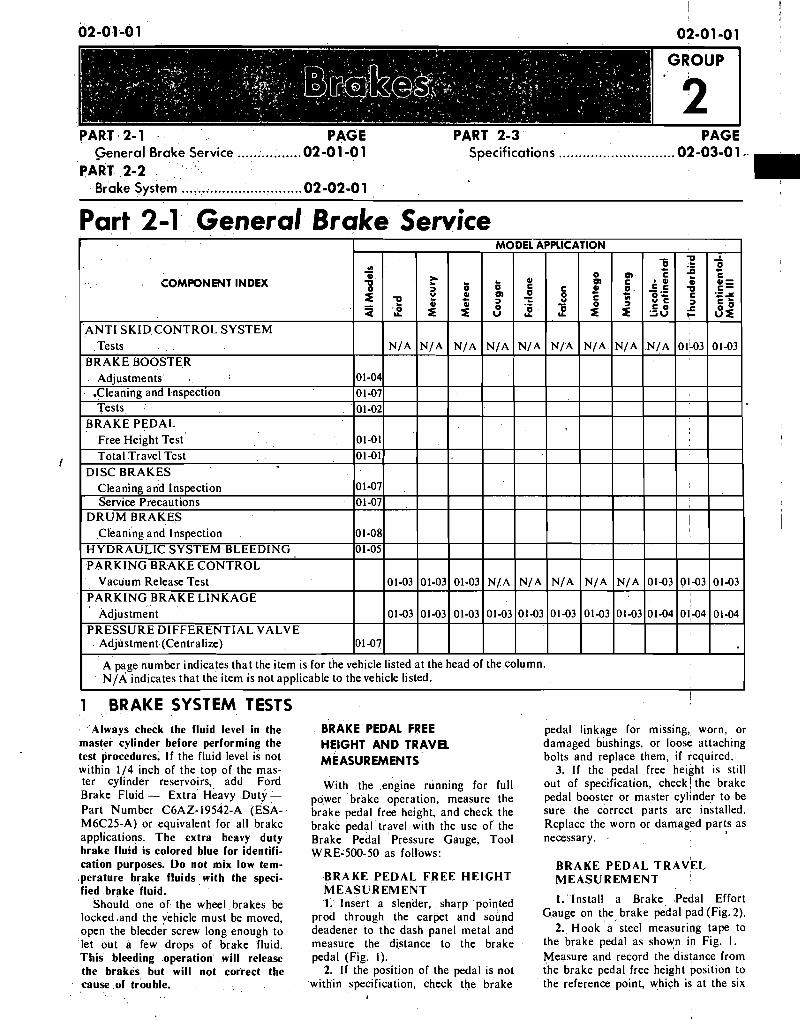
PART 2-1 PAGE ................ General Brake Service 02-01 -0 1
PART 2-2 Brake System .............................. 02-02-0 1
PART 2-3 PAGE Specifications ............................. 02-03-0 1 ..
Part . . 2-1 General Brake Service
. . COMPONENT INDEX
I
Adjlistment (Centralize) I
I A page number indicates that the item is for the vehicle listed at the head of the column. NIP; indicates that the item is not applicable to the vehicle listed.
.Always check the fluid level in the master cylinder before performing the test procedures. If the fluid level is not within 114 inch of the top of the mas- ter cylinder reservoirs,, add Ford Brake Fluid - Extra Heavy Duty - Part Number C~AZ-19542-A (ESA- M6C25-A) or equivalent for all brake applications. The -extra heavy duty brake fluid is colored blue for identifi- cation purposes.' Do not mix low tem- .perature brake fluids with the speci- fied brake fluid.
Should one of the wheel ,brakes be locked ,and the vehicle must be moved, open the bleeder screw long enough to let out a few drops of brake fluid. This bleeding operation will release the brakes but will not correct the cause of trouble.
BRAKE PEDAL FREE HEIGHT A N D TRAVEL MEASUREMENTS
With .the ,engine running for full power brake operation, measure the brake pedal free height, and check the brake pedal.travel with the use of ' the Brake Pe'dal Pressure Gauge, Tool WREL500-50 as follows:
B R A K E P E D A L F R E E H E I G H T M E A S U R E M E N T 1. Insert a slender, sharp pointed
prod through the carpet and sound deadener to the dash panel metal and measure the distance to the brake pedal (Fig. I).
2. If the position of the pedal is not within specification, check the brake
pedal linkage for missing, worn, or damaged bushings, or loose attaching bolts and replace them, i f required.
3. If the pedal free height is still out of spec~fication, check! the brake pedal booster or master cylinder to be sure the correct parts are installed. Replace the worn or damaged parts as necessary. .
B R A K E P E D A L T R A V E L M E A S U R E M E N T '
1. Install a Brake Pedal Effort Gauge on the brake pedal pad (Fig. 2).
2. Hook a steel measuring tape to the brake pedal as shown in Fig. I . Measure and record the distance from the brake pedal free height position to the reference point, which is at the six
02 -0 1 -02 Brakes 02-0 1 -02
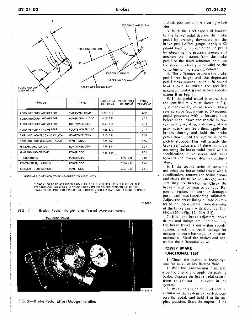
STEERING WHEEL RIM
N 0 T E : A B B DIMENSION TO BE MEASURED TO SHEET M E T A L
C DIMENSION TO BE MEASURED PARALLEL T O THE V E R T I C A L CENTERLINE OF THE STEERING COLUMN WlTH A 50 POUND LOAD APPLIED TOTHE CENTERLINE OF THE J R A K E PEDAL PAD. (CHECKS ON POWER BRAKE VEHICLES MADE WlTH ENGINE RUNNING
b
FIG. 1 - Brake Pedal He igh t a n d Travel Measurements
o'clock position on the steering wheel r im.
3. Wi th the steel tape sti l l hooked to the brake pedal depress the brake pedal by pressing downward on the brake pedal effort gauge. ply a 50 pound load to the center of the pedal by observing the pressure gauge, and measure the distance from the brake pedal to the fixed reference point on the steering wheel r i m parallel to the centerline of the steering column.
4. The difference between the brake pedal free height and the depressed pedal measurement under a 50 pound load should be within the specified maximum pedal travel service specifi- cation B in Fig. I.
5. I f the pedal travel is more than the specified maximum shown i n Fig. I, dimension C, make several sharp reverse stops (equivalent to 50 pounds pedal pressure) with a forward stop before ea'ch. Move the vehicle in rev- erse and forward for a distance 0 f . a ~ - proximately ten feet; then, apply the brakes sharply and hold the brake pedal down unt i l the vehicle is com- pletely stopped. This wi l l actuate the brake self-adjusters. I f these .stops do not bring the brake pedal travel within specification, make several additional forward and reverse stops as outlined above.
6. I f the second series of stops do not bring the brake pedal travel within specification, remove the brake drums and check the brake adjusters to make sure they are functioning. Check the brake linings for wear or damage. Re- pair or replace all worn or damaged parts and non-functioning adjusters. Adjust the brake lining outside diame- ter to the approximate inside diameter of the brake drum with Rotunda Tool HRE-8650 (Fig. 12, Part 2-2).
7. I f all the brake adjusters, brake drums and linings are functional and the brake travel is not within specifi- cations, check the pedal linkage for missing or worn bushings, or loose at- tachments. Bleed the brakes and cen- tralize the differential valve.
POWER BRAKE FUNCTIONAL TEST
I. Check the hydraulic brake sys- tem for leaks or insufficient fluid.
2. With the transmission in neutral, stop the engine and appIy the, parking brake. Depress the brake pedal several times to exhaust all vacuum i n the system.
3. Wi th the engine shut off .and all vacuum in the system exhausted. deD-
FIG. 2-Brake Pedal E f fo r t G a u g e Instal led ress the pedal, and hold i t i n the ab- .plied position. Start the engine. I f the
i I
!
02-0 1-03 Brakes 02-01-03 ,
vacuum system is operating, the pedal be adapted to any other vacuum hose Pump Tester 345. This can be nccom- will tend to fall away under foot pres- or rubber connector in the vacuum plished by removing the hose from sure and less pressure will be required systems. each component and attaching it to to hold the pedal in the applied posi- Failure to maintain 10 inches of the vacuum gauge. Connect two dis- tion. I f no action is felt, the vacuum vacuum (Hg.) during vacuum system tributor tester vacuum hose adapters .booster system is not functioning. tests could be caused by a loose hose together with a coupling as a connec- ,
I f the brake pedal movement feels connection, resulting in a vacuum tor to attach the gauge. A nlinimum ,
spongy, bleed the hydraulic system to leak., When checking for 'vacuum be- of ten inches of vacuum is required to remove air from the system. Refer to tween two points, trace the hose along actuate the parking brake vacuum I
Hydraulic System Bleeding, Part I, ' the entire routing to be sure it is not motor. Do not remove any of the vac- Section 2. crossed with another hose and con- uum hoses from the junction block
nected to the wrong connection. unless the junction block is being re- V A C U U M . TESTS-VACUUM All of the vacuum parking brake placed, as the plastic nipples are thin RELEASE PARKING BRAKES control checks are to be performed and very brittle and damage may re-
with the engine running a t idle speed. sult. I f a minimum reading is not . Leaks in the parking brake hoses or present when checking each of the
Visually check the 'peration of the a d isconnected o r imprope r ly con- a f o r e m e n t ioned compo'nents , they brake' linka'ge as lhe brake pedal is nected hose can usually be found by must be replaced. depressed. Then, check the operation l i s t en ing for a hissing sound the of the brake linkage when the manual hose r o u t i n g s , Under no circumstances R O A D TEST r e l e a s e l e v e r i s ac t iv i a t ed . These should air pressure be applied to the checks should indicate whether the system as the actuator dia- A road test should be conducted manual parking brake control linkage phragm in the parking brake vacuum only when the operator is sure the is operating properly or requires re- motor may be damaged. brakes will stop the vehicle. pair or adjustment due to inability of I. Star t the engine and run it a t I f the road test reveals h e or more Ihe parking brake lo idle speed. With the transmission shift p r o b ~ m conditions, correct all , moderate vehicle movement. Perform control i n neutral , depress the parking functions of the vacuum system, brake tests of the parking brake system and brake pedal to a p p l y the parking booster and hydraulic system prior to
'
controls after making certain the link- - brake, M~~~ the transmission shift removing brake drums, brake calipers, age and m a n u a l c o n t r o l s control to D range and observe the brake shoes and l i n i n g s l or backing , properly. parking brake pedal to see that the plates.
When testing a parking brake vacu- pedal moves upward and the parking um release system, 'a minimum of 10 brake releases. I f the parking brake ANTI-SKID CONTROL inches of vacuum (Hg.) should be releases, the parking brake vacuum available at all points where vacuum is control is working properly. SYSTEM TESTS
applied. This can be checked with a 2. I f the parking brake does not re- No adjustments or repairs are to be Rotunda Fuel Pump Tester Gauge lease, test for vacuum a t the steering performed on the skid co?trol system. , (ARE345) and two Distributor Tester column neutral switch port in the Damaged or worn parts are to be re- hose adapters (Marked Q) connected junction block, vacuum lines and the placed. together with a coupling. This allows parking brake release vacuum motor. Refer to Ford C a r and Truck Diag- the Fuel Pump Tester Gauge hose to Use the Rotunda Vacuum and Fuel nosis Manual for Testinglprocedures. ,
I
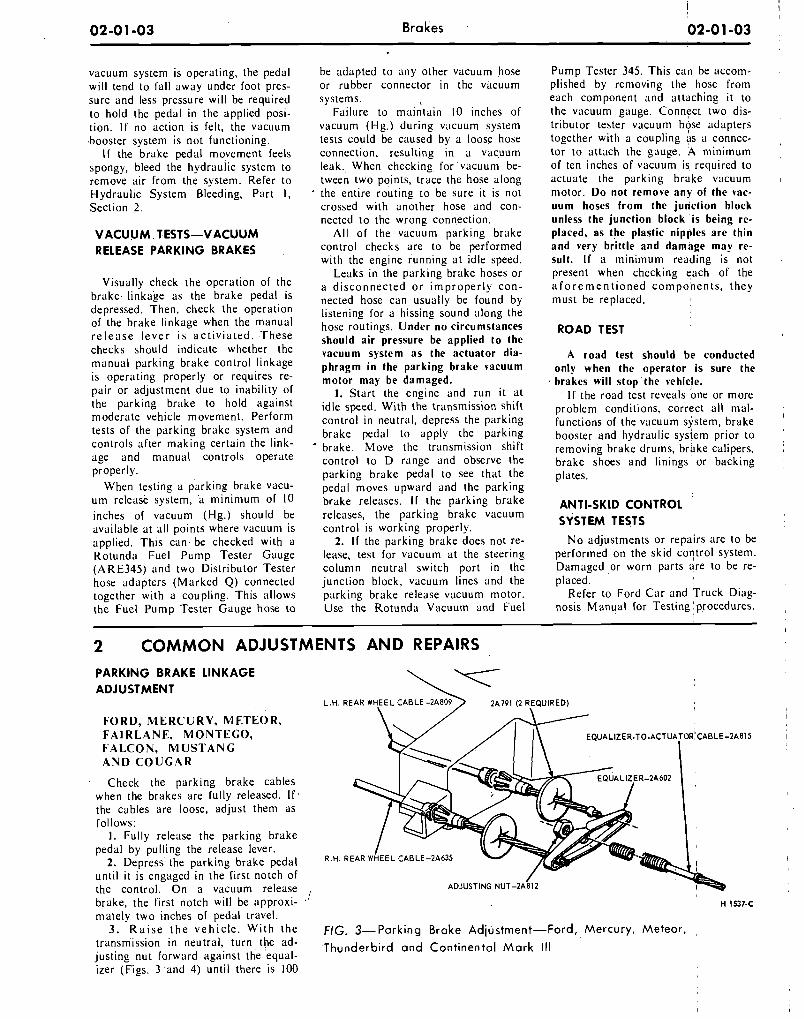
2 COMMON ADJUSTMENTS AND REPAIRS PARKING BRAKE LINKAGE ADJUSTMENT
L.H. R E A R WHEEL CABLE-2A809 ) 2 A P l (2 R,EQUlREDI
F O R D , M E R C U R Y , M E T E O R , F A I R L A N E , M O N T E G O , F A L C O N , M U S T A N G A N D C O U G A R
Check the parking brake cables when the brakes are fully released. I f ' the cables are loose, adjust them as follows:
I . Fully release the parking brake pedal by pulling the release lever.
2. Depress the parking brake pedal R.H.
until it is engaged in the first notch of the control. On a vacuum release , ADJUSTING NUT-2A
brake, the first notch will be approxi- , ' H 1537-c
mately two inches of pedal travel. 3. R a i s e t h e v e h i c l e . Wi th the FIG. 3-Parking Brake Adjirstrnent-Ford, Mercury , Meteo r , ,
transmission in neutral, t u rn , the ad- Thunderbird and Continental M a r k justing nut forward against the equal- izer (Figs. 3 and 4) until there is 100
02-0 1 -04 Brakes
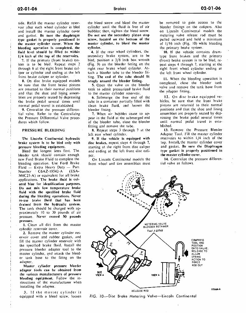
I f t- lb breakaway torque. The breaka- way torque is the torque required to
' turn the rear wheels the direction of I
forward rotation with a torque wrench and tool shown in Fig. 5. The torque measurement must be made relative to the center line of the wheel.
4. Release the parklng brake, and I check to make sure that the brake : shoes return to the fully released posi-
tion. I 5. Depress the parking brake pedal
to the third notch. Under normal con- ditions, this wi l l hold the vehicle satis-
, factorily. 6. Release the parking brake again,
and check as in step 4. 7. I f the rear brakes do not fully
1 release, check the cables for kinks or
I binds. Free the cables as required. 8. Lower the vehicle. Remove the
torque wrench and tool. Install the wheel attaching nuts and torque them
I to specification. Install the wheel cover.
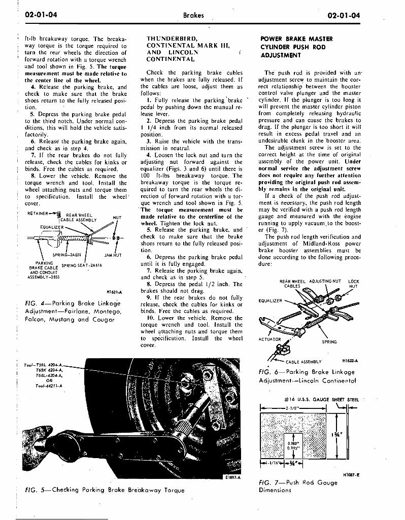
RETAINER REAR WHEEL
P A ~ K I N G I : BRAKE CABLE SPRING SEAT-2A616
I AND CONDUIT
, FIG. 4-Parking Brake L inkode ( Adjustment-Fairlane, Montego , ! Falcon, M u s t a n g a n d C o u g a r
T H U N D E R B I R D , C O N T I N E N T A L M A R K Ill, A N D L I N C O L N i C O N T I N E N T A L
Check the parking brake cables when the brakes are fully released. I f the cables are loose, adjust them as follows: I. Fully release the parking ' brake
pedal by pushing down the manual re- lease lever.
2. Depress the parking brake pedal 1 114 inch from its normal released position.
3. Raise the vehicle with the trans- mission in neutral.
4. Loosen the lock nut and turn the adjusting nut forward against the equalizer (Figs. 3 and 6) until there is 100 ft-lbs breakaway torque. The breakaway torque is the torque re- quired to turn the rear wheels the di- rection of forward rotation with a tor- que wrench and tool shown i n Fig. 5. The torque measurement must be made relative to the centerline of the wheel. Tighten'the lock nut.
5. Release the parking brake, and check to make sure that the brake shoes return to the fully released posi- tion.
6. Depress the parking brake pedal unt i l i t is fully engaged.
7. Release the parking brake again, and check as in step 5.
8. Depress the pedal 112 inch. The brakes should not drag.
9. I f the rear brakes do not fully release, check the cables for kinks or binds. Free the cables as required.
10. Lower the vehicle. Remove the torque wrench and tool. Install the wheel attaching nuts and torque them to specification. Install the wheel cover.
: FIG. 5-Checking Park ing Brake B r e a k a w a y Torque I
POWER BRAKE MASTER CYLINDER PUSH ROD ADJUSTMENT
The push rod is provided with an' adjustment screw to maintain the cor- rect relationship between the booster control valve plunger and the master cylinder. I f the plunger is too long i t w i l l prevent the master cylinder piston from completely releasing hydraulic pressure and can cause the brakes to drag. I f the plunger is too short i t wi l l result i n excess pedal travel and an undesirable clunk i n the booster area.
The adjustment screw is set to the correct height at the time of original assembly of the power unit. Under normal service the adjustment screw does not require any further attention providing the original push rod assem- bly remains i n the original unit.
I f a check of the push rod adjust- ment is necessary, the push rod length may be verified with a push rod length gauge and measured with the engine running to apply vacuum,to the boost- er (Fig. 7).
The push rod length verification and adjustment o f Midland-Ross power brake booster assemblies must be done according to the following proce- dure:
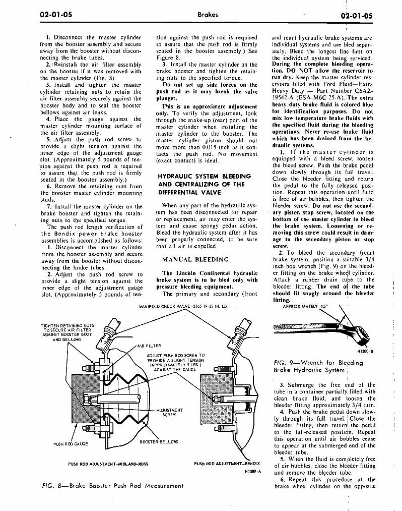
REAR WHEEL ADJUSTING NUT LOCK
EQUALIZER \ \
/L CABLE ASSEMBLY H1611-A
FIG. 6-Parking Brake L inkage
Adjustment-Lincoln Cont inenta l
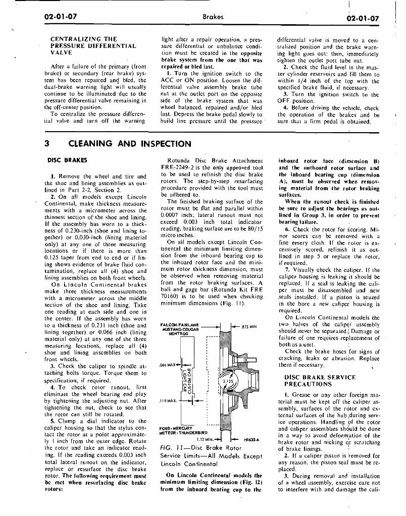
#16 U.S.S. GAUGE SHEET STEEL '
1 - 2 . 7 / 8 " - 1 4I-
H1087-E
FIG. 7-Push Rod G a u g e Dimensions
02-0 1 -05 Brakes
1. Disconnect the master cylinder from the booster assembly and secure away 'from the booster without discon- necting the brake tubes.
2.1 Reinstall the air filter assembly on the booster i f it was removed with the master cylinder (Fig. 8).
3. Install and tighten the master cylinder retaining nuts to retain the air filter assembly securely against the booster body and to seal the booster bellows against air leaks.
4. Place the gauge against the master cylinder mounting surface of the air filter assembly.
5. Adjust the push rod screw to provide a slight tension against the inner edge of the adjustment gauge slot. (Approximately 5 pounds of ten- 'sion against the push rod is required to assure that the push rod is firmly seated in the booster assembly.)
6. Remove the retaining nuts from the booster master cylinder mounting studs.
7. ,Install the master cylinder on the brake booster and tighten the retain- ing nuts to the specified torque.
The push rod length verification of t h e B e n d i x p o w e r b r a k e booster assemblies is accomplished as follows:
1. Disconnect the master cylinder from the booster assembly and secure away from the booster without discon- necting the brake tubes.
2. Adjust the push rod screw to provide a slight tension against the inner edge of the adjustment gauge slot. (Approximately 5 pounds of ten-
sion against the push rod is required to assure that the push rod is firmly seated in the booster assembly.) See Figure 8.
3. Install the master cylinder on the brake booster and tighten the retain- ing nuts to the specified torque.
D o not set up side forces on the .push rod as it may break the valve plunger.
This is an approximate adjustment only. T o verify the adjustment, look through the make-up (rear) port of the master cylinder when installing the master cylinder to the booster. The master cylinder piston should not move more than 0.015 inch as it con- tacts the push rod. No movement (exact contact) is ideal.
HYDRAULIC SYSTEM BLEEDING A N D CENTRALIZING O F THE DIFFERENTIAL VALVE
When any part of the hydraulic sys- tem has been disconnected for repair or replacement, air may enter the sys- tem and cause spongy pedal action. Bleed the hydraulic system after it has been properly connected, to be sure that all air is expelled.
M A N U A L B L E E D I N G
The Lincoln Continental hydraulic brake system is to be bled only with pressure bleeding equipment.
The primary and secondary (front
MANIFOLD CHECK VALVE-2365 19.25 IN. LB.
ADJUST PUSH ROO SCREW T O
ADJUSTMENT
PUSH ROD ADJUSTMEHT-MIDLMD-ROSS
FIG. 8-Brake Booster Push Rod Measurement
and rear) hydraulic brake systems are individual systems and are bled separ- ately. Bleed the longest line first on the individual system being serviced. During the complete bleeding opera- tion, D O N O T allow the reservoir to run dry. Keep the master cylinder res- ervoirs filled with Ford Fluid-Extra Heavy Duty - P q t Number C6AZ- 19542-A (ESA-M6C 25-A). the extra heavy duty brake fluid is colored blue for identification purposes. D o not mix low temperature brake fluids with the specified fluid during the bleeding operations. Never re-use brake fluid which has been drained fro'm the hy- draulic systems.
1. I f t h e m a s t e r c y 4 i n d e r i s equ~pped with a bleed screw, loosen the bleed screw. Push the brake pedal down slowly through its full travel. Close the bleeder fitting and return the pedal to the fully released posl- tion. Repeat this operation ,until fluid is free of air bubbles, then tighten the bleeder screw. D o not use the second- ary piston stop screw, located on the bottom of the master cylinder to bleed the brake system. Looseni,ng or re- moving this screw could result in dam- age to the secondary piston or stop screw.
2. To bleed the secondary (rear) brake system, position a suitable 318 inch box wrench (Fig. 9) on the bleed- er fitting on the brake wheel cylinder. Attach a rubber drain tube to the bleeder fitting. The end of the tube
I I
should fit snugly around the bleeder fittine. -
APPROXIMATELY 25' \
FIG. 9-Wrench fo r Bleeding Brake Hydraulic System
I I I
3. Submerge the free end of the tube in a container partially filled with clean brake fluid, and loosen the bleeder fitting approximately 314 turn.
4. Push the brake pedal down slow- ly through its full travel. 'Close the bleeder fitting, then return1 the pedal I
to the full-released position. Repeat this operation until air bubbles cease to appear at the submerged end of the bleeder tube.
5. When the fluid is completely free of air bubbles, close the bleyder fitting and remove the bleeder tube.
6. Repeat t h ~ s procedure a t the brake wheel cylinder on the opposite
Brakes 02-0 1 -06
side. Refil l the master cylinder reser- , voir after each wheel cylinder is bled
and install the master cylinder cover and gasket. Be sure the diaphragm
; type gasket is properly positioned i n ; the master cylinder cover. When the I bleeding operation is completed, the : fluid level should be filled to within
114 inch of the top of the reservoirs. / 7. I f the primary (front brake) sys-
/ tem is to be bled. Repeat steps 2 through 6 at the right front brake cal-
1 iper or cylinder and ending at the left front brake caliper or cylinder.
8. On disc brake equipped models ; be sure that the front brake pistons I are returned to their normal positions I and that the shoe and liqing assem-
blies are properly seated by depressing : the brake pedal several times until ; normal pedal travel is established. I 9. Centralize the pressure differen-
tial valve. Refer to the Centralizing the Pressure Differential Valve proce-
I dures which follow. I
PRESSURE B L E E D I N G
The Lincoln Continental hydraulic brake system is to be bled only with pressure bleeding equipment.
Bleed the longest lines first. The bleeder tank should contain enough new Ford Brake Fluid to complete the bleeding operation. Use Ford Brake Fluid - Extra Heavy Duty - Part Number , G6AZ- 19542-A (ESA- M6C25-A) or equivalent for all brake applications. The brake fluid is col- ored blue for identification purposes. D o not mix low temperature brake fluid with the specified brake fluid during the bleeding operations. Never re-use brake fluid that has been drained from the hydraulic system. The tank should be charged with ap- proximately 10 to 30 pounds of air pressure. Never exceed 50 pounds pressure.
1. Clean al l dir t from the master cylinder reservoir cover.
2. Remove the master cylinder res- t ervoir cover and rubber gasket, and ' f i l l the master cylinder reservoir with I the specified brake fluid. Install the
pressure bleeder adapter tool to the i master cylinder, and attach the bleed- : er tank hose to the fittng on the I adapter. 1 Master cylinder pressure bleeder / adapter tools can be obtained from 1 the various manufacturers of pressure
bleeding equipment. Follow the in- structions of the manufacturer when installing the adapter.
3. I f t h e m a s t e r c y l i n d e r i s equipped with a bleed screw, loosen
the bleed screw and bleed the master cylinder until the fluid is free of air bubbles; then, tighten the bleed screw. D o not use the secondary piston stop screw, located on the bottom of the master cylinder, to bleed the master cylinder.
4. I f the rear wheel cylinders, the secondary brake system, are to be bled, position a 318 inch box wrench (Fig. 9) on the bleeder fitt ing on the right rear brake wheel cylinder. A t - tach a bleeder tube to the bleeder f i l - ting. The end of the tube should fit snugly around the bleeder fitting.
5. Open the valve on the bleeder tank to admit pressurized brake fluid to the master cylinder reservoir.
6. Submerge the free end of the tube in a container partially filled with clean brake fluid, and loosen the bleeder fitting.
7. When air bubbles cease to ap- pear i n the fluid at the submerged end of the bleeder tube, close the bleeder fitt ing and remove the tube.
8. Repeat steps 3 through 7 at the left rear wheel cylinder.
9. I f the vehicle, is equipped with disc brakes, repeat,steps 4 through 7, starting at the right front disc caliper and ending at the left front disc cali- per.
On Lincoln Continental models the front wheel and tire assemblies must
be removed to gain access to the bleeder fittings on the calipers. Also on Lincoln Continental models the metering valve release rod must be pulled outward and held a minimum of 1/16 inch (Fig. 10) while bleeding the primary brake system.
10. I f the vehicle contains drum- '
type front brakes and the primary (front) brake system is to be bled, re- peat steps 4 through 7, starting at the right front wheel cylinder ending at the left front wheel cylinder.
11. When the bleeding operation i s completed, close the bleeder tank valve and remove the tank hose from the adapter fitting.
12. O n disc b rake equipped ve- hicles, be sure that the front brake pistons are returned to their. normal positions and that the shoe and lining assemblies are properly seated by dep- ressing the brake pedal several times unt i l normal pedal travel is esta- blished.
13. Remove the Pressure Bleeder Adapter Tool. F i l l the master cylinder ,reservoirs to within 114 inch of the top. Install. the master cylinder cover aid gasket. Be sure the Diaphragm type gasket is properly positioned i n the master cylinder cover.
14. Centralize the pressure differen- tial valve as follows.
/ Tool J-21741
COMPRESS TOOL AND POSITION ONTO VALVE. RELEASE TO ALLOW SPRING ACTION TO FORCE ROD OUT
RELEASE ROD
FIG. 70-Gisc Brake Mete r ing Valve-Lincoln Cont inenta l
02-01 -07 Brakes
C E N T R A L I Z I N G T H E P R E S S U R E D I F F E R E N T I A L V A L V E
After a failure of the primary (front brake) or secondary (rear brake) sys- tem has been repaired and bled, the dual-brake warning light will usually continue to be illuminated due to the pressure differential valve remaining in the off-center position.
To centralize the pressure differen- tial valve and turn off the warning
light after a repair operation, a pres- sure differential or unbalance condi- tion must be created in the opposite brake system from the one that was repaired or bled last.
1. Turn the ignition switch to the ACC or ON position. Loosen the dif- ferential valve assembly brake tube nut at the outlet port on the opposite side of the brake system that was wheel balanced, repaired and/or bled last. Depress the brake pedal slowly to build line pressure until the pressure
3 CLEANING AND INSPECTION
DlSC BRAKES
I. Remove the wheel and tire and the shoe and lining assemblies as out- lined in Part 2-2, Section 2.
2. On all models except Lincoln Continental, make thickness measure- ments with a micrometer across the thinnest section of the shoe and lining. I f the assembly has worn to a thick- ness of 0.230-inch (shoe and lining to- gether) or 0.030-inch (lining material only) at any one of three measuring locations or i f there is more than 0.125 taper from end to end or i f lin- ing shows evidence of brake fluid con- tamination, replace all (4) shoe and lining assemblies on both front wheels.
O n Linco ln Continental brakes make three thickness measurements with a micrometer across the middle section of the shoe and lining. Take one reading at each side and one in the center. I f the assembly has worn to a thickness of 0.231 inch (shoe and lining together) or 0.066 inch (lining material only) at any one of the three measuring locations, replace all (4) shoe and lining assemblies on both front wheels.
3. Check the caliper to spindle at- taching bolts torque. Torque them to specification, i f required.
4. To check rotor runout, first eliminate the wheel bearing end play by tightening the adjusting nut. After tightening the nut, check to see that the rotor can still be rotated.
5. Clamp a dial indicator to the caliper housing so that the stylus con- tact the rotor at a point approximate- ly I inch from the outer edge. Rotate the rotor and take an indicator read- ing. I f the reading exceeds 0.003 inch total lateral runout on the indicator, replace or resurface the disc brake rotor. The following requirement must be met when resurfacing disc brake rotors:
Rotunda Disc Brake Attachment FRE-2249-2 is the only approved tool to be used to refinish the disc brake rotors. The step-by-step resurfacing procedure provided with the tool must be adhered to.
The finished braking surface of the rotor must be flat and parallel within 0.0007 inch; lateral runout must not exceed 0.003 inch total indicator reading, braking surface are to be 801 15 micro inches.
On all models except Lincoln Con- tinental the minimum limiting dimen- sion from the inboard bearing cup to the inboard rotor face and the mini- mum rotor thickness dimension, must be observed when removing material from the rotor braking surfaces. A ball and gage bar (Rotunda Kit FRE 70160) is to be used when checking minimum dimensions (Fig. I I).
FALCON-FAIRLANE MUSTANG-COUGAR 4 k 'IN
MONTEGO
METEOR - THUNDERBIRD I I 1.12 M I N . ~ 1- H1633-A
FIG. 1 1-Disc Brake Rotor Service Limits-All Models Except Lincoln Continental
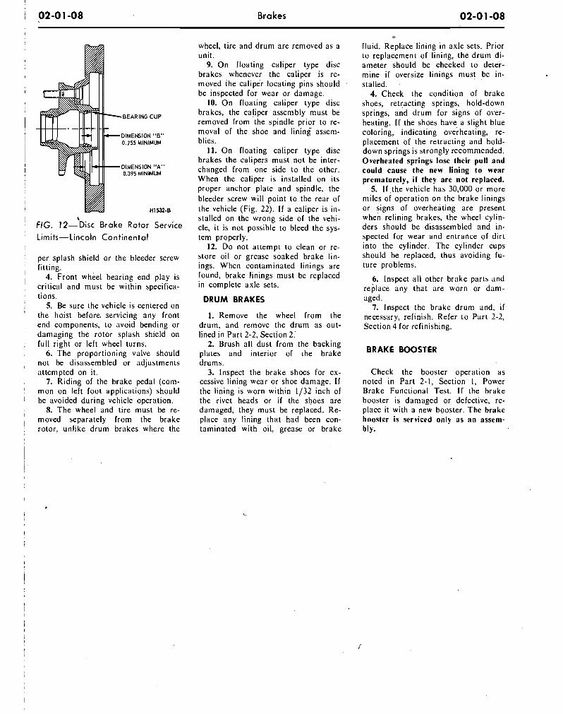
O n Lincoln Continental models the minimum limiting dimension (Fig. 12) from the inboard bearing cup to the
differential valve is moved to a cen- tralized position and the brake warn- ing light goes out; then, immediately tighten the outlet port tube nut.
2. Check the fluid level in the mas- ter cylinder reservoirs and f i l l them to within 1/4 inch of the top with the specified brake fluid, i f necessary.
3. Turn the ignition switch tb the O F F position.
4. Before driving the vehicle, check the operation of the brakes and be sure that a firm pedal is obtained.
inboard rotor face (dimension B) and the outb.oard rotor surface and the inboard bearing c u p (dimension A), must be observed when remov- ing material from the rotor braking surfaces.
When the runout check, is finished be sure to adjust the bearings as out- lined in Group 3, in order to prevent bearing failure.
6. Check the rotor for scoring. Mi- nor scores can be removed with a fine emery cloth. I f the rotor is ex- cessively scored, refinish it as out- lined in step 5 or replace the rotor, i f required.
7. Visually check the caliper. I f the caliper housing is leaking it should be replaced. I f a seal .is leaking the cali- per must be disassembled and new .seals installed. I f a pisto,n is seazed in the b.ore a new caliper housing is required.
On Lincoln Continental models the two halves of the caliper assembly should never be separated.1 Damage or failure of one requires replacement of both as a unit.
Check the brake hoses for signs of cracking, leaks or abrasion. Replace them if necessary.
D l S C B R A K E S E R V I C E P R E C A U T I O N S
1. Grease or any other 'foreign ma- terial must be kept off the caliper as- sembly, surfaces of the rotor and ex- ternal surfaces of the hub during serv- ice operations. Handling ?f the rotor and caliper assemblies should be done in a way to avoid deformhion of the brake rotor and nicking o,r scratching of brake linings.,
2. If a caliper piston is removed for any reason, the plston seal must be re- placed.
3. During removal and installation of a wheel assembly, exercise care not to ~nterfere with and damage the cali-
Brakes
BEARING CUP
DIMENSION "0" 0.755 MINIMUM
DIMENSION "A" 0.395 MINIMUM
Hl532-B \
FIG. 12-Disc Brake Rotor Servke
Limits-Lincoln Continental
per splash shield or the bleeder screw fitting.
4. Front wheel bearing end play is critical and must be within specifica- tions.
5. Be sure the vehicle is centered on the hoist before. servicing any front end components, to avoid bending or damaging the rotor splash shield on full right or left wheel turns.
6. The proportioning valve should not be disassembled or adjustments attempted on it.
7. Riding of the brake pedal (com- mon on left foot applications) should be avoided during vehicle operation.
8. The wheel and tire must be re- moved separately from the brake rotor, unlike drum brakes where the
wheel, tire and drum are removed as a unit.
9. On floating caliper type disc brakes whenever the caliper is re- moved the caliper locating pins should .
be inspected for wear or damage. 10. On floating caliper type disc
brakes, the caliper assembly must be removed from the spindle prior to re- moval of the shoe and lining assem- blies.
11. On floating caliper type disc brakes the calipers must not be inter- changed from one side to the other. When the caliper is installed on its proper anchor plate and spindle, the bleeder screw will point to the rear of the vehicle (Fig. 22). If a caliper is in- stalled on the wrong side of the vehi- cle, it is not possible to bleed the sys- tem properly.
12. Do not attempt to clean or re- store oil or grease soaked brake lin- ings. When contaminated linings are found, brake linings must be replaced in complete axle sets.
DRUM BRAKES
1. Remove the wheel from the drum, and remove the drum as out- lined in Part 2-2, Section 2.
2. Brush all dust from the backing plates and interior of the brake drums.
3. Inspect the brake shoes for ex- cessive lining wear or shoe damage. If the lining is worn within 1/32 inch of the rivet heads or if the shoes are damaged, they must be replaced. Re- place any lining that had been con- taminated with oil, grease or brake
fluid. Replace lining in axle sets. Prior to replacement of lining, the drum di- ameter should be checked to deter- mine i f oversize linings must be in- stalled.
4. Check the condition of brake shoes, retracting springs, hold-down springs, and drum for signs of over- heating. If the shoes have a slight blue coloring, indicating overheating, re- placement of the retracting and hold- down springs is strongly recommended. ~ v e r h e a t e d ~ s ~ r i n ~ s lose their pull and could cause the new lining to wear prematurely, i f they are not replaced.
5. I f ,the vehicle has 30,000 or more miles of operation on the brake linings or signs of overheating are present when relining brakes, the wheel cylin- ders should be disassembled and in- spected for wear and entrance of dirt into the cylinder. The cylinder cups should be replaced, thus avoiding f u - ture problems.
6. Inspect all other brake parts and replace any that are worn or dam- aged.
7. Inspect the brake drum and, i f necessary, refinish. Refer to Part 2-2, Section 4 for refinishing.
BRAKE BOOSTER
Check the booster operation as noted in Part 2-1, Section I, Power Brake Functional Test. I f the brake booster is damaged or defective, re- place it with a new booster. The brake booster is serviced only as an assem- bly;
Brake System
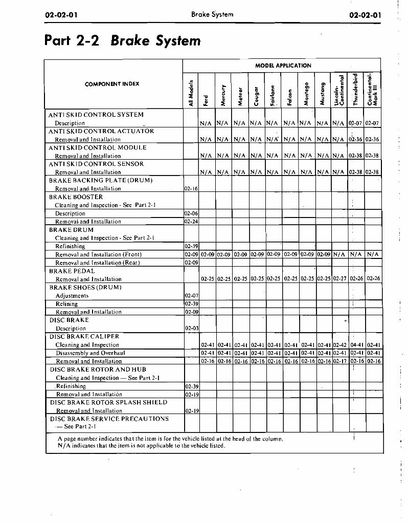
Part 2-2 Brake System
COMPONENT INDEX
ANTl SKID CONTROL SYSTEM
ANTl SKIDCONTROL MODULE
.- See Part 2- 1
A page number indicates that the item is for the vehicle listed at the head of the column. I
N/A indicates that the item is not applicable to the vehicle listed.
MODEL APPLICATION
6
;= -t 51"
o m
z" c - 8 2
m c 6
3
6
z g i
"l - i I = * m , O .,L
2 ,
i . E , = . . c , $ ; , ,
56 g u
= T = ' r ?
lc
t. , ;
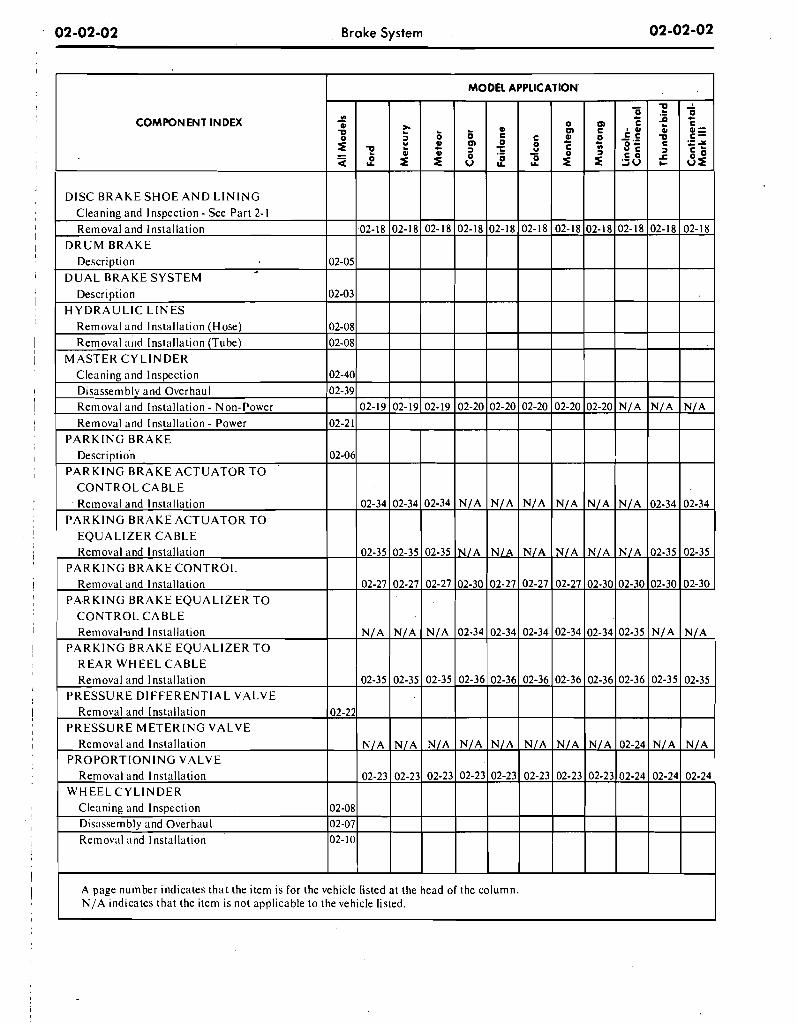
02-02-02 Brake System 02-02-02
COMPONENT INDEX
Removal and Installation - Non-Power Removal and Installation - Power
P A R K I N G BRAKE Description
PARKING BRAKE ACTUATOR T O C O N T R O L CABLE Removal and installation
P A R K I N G BRAKE ACTUATOR T O EQUALIZER CABLE Removal and Installation
PARKING BRAKE C O N T R O L Removal and Installation
PARKING BRAKE EQUALIZER T O C O N T R O L CABLE Removal-und Installation
PARKING BRAKE EQUALIZER T O REAR W H E E L C A B L E Removal and Installation
P R E S S U R E DIFFERENTIAL VALVE Removal and Installation
P R E S S U R E M E T E R I N G VALVE Removal and Installation
P R O P O R T I O N I N G VALVE Removal and Installation
WHEEL: C Y L I N D E R Cleaning and Inspection Disassembly and Overhaul Removal and Installation
A page number indicates that the item is for the NJA indicates that the item is not applicable to the vehicle listed.
02-2 1
02-06
02-22
02-08 02-07 02-10
vehicle
02-20
N/A
N / A
02-30
02-34
02-36
N/A
02-23
the
02-19
02-34
02-35
02-27
N/A
02-35
N/A
02-23
listed
02-19
02-34
02-35
02-27
N/A
02-35
N/A
02-23
a t the
02-20
N/A
N/A
02-27
02-34
02-36
N/A
02-23
column.
02-20
N/A
N/A
02-27
02-34
02-36
N/A
02-23
02-19
02-34
02-35
02-27
N/A
02-35
N/A
02-23
head of
02-20
N/A
NIA
02-27
02-34
02-36
N/A
02-23
02-20
N/A
NIA
02-30
02-34
02-36
N/A
02-23
N/A
N/A
N/A
02-30
02-35
02-36
02-24
02-24
N/A
02-34
02-35
02-30
N/A
02-35
N/A
02-24
N/A
02-34
02-35
02-30
N/A
02-35
N/A
02-24
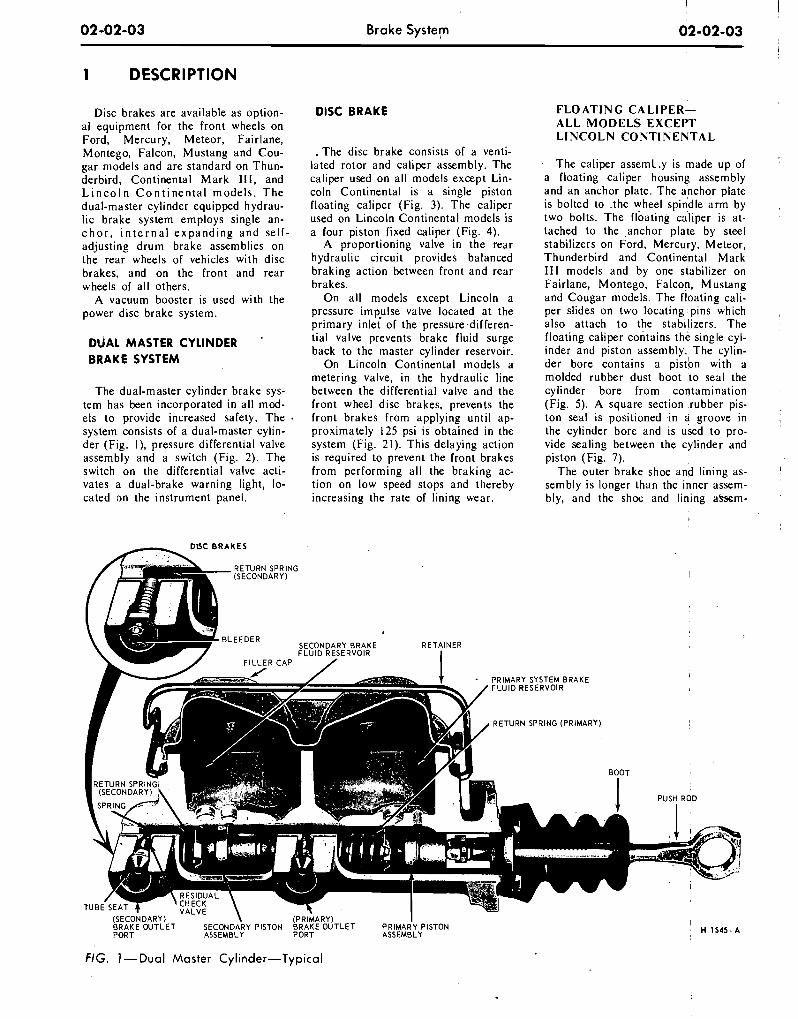
02-02-03 Brake System 02-02-03 1
1 DESCRIPTION
Disc brakes are available as option- al equipment for the front wheels on Ford, Mercury, Meteor, Fairlane, Montego, Falcon, Mustang and Cou- gar models and are standard on Thun- derbird, Continental Mark I l l , and L i n c o l n C o n t i n e n t a l models. The dual-master cylinder equipped hydrau- lic brake system employs single an- c h o r , i n t e r n a l expanding and self- adjusting drum brake assemblies on the rear wheels of vehicles with disc brakes, and on the front and rear wheels of all others.
A vacuum booster is used with the power disc brake system.
DUAL MASTER CYLINDER . BRAKE SYSTEM
The dual-master cylinder brake sys- tem has been incorporated in all mod- els to provide increased safety. The system consists of a dual-master cylin- der (Fig. I), pressure differential valve assembly and a switch (Fig. 2). The switch on the differential valve acti- vates a dual-brake warning light, lo- cated on the instrument panel.
DlSC BRAKE
. The disc brake consists of a venti- lated rotor and caliper assembly. The caliper used on all models except Lin- coln Continental is a single piston floating caliper (Fig. 3). The caliper used on Lincoln Continental models is a four piston fixed caliper (Fig. 4).
A proportioning valve in the rear hydraulic circuit provides balanced braking action between front and rear brakes.
On all models except Lincoln a pressure imp!lse valve located at the primary inlet of the pressure differen- tial valve prevents brake fluid surge back to the master cylinder reservoir.
On Lincoln Continental models a metering valve, in the hydraulic line between the differential valve and the front wheel disc brakes, prevents the front brakes from applying until ap- proximately 125 psi is obtained in the system (Fig. 21). This delaying action is required to prevent the front brakes from performing all the braking ac- tion on low speed stops and thereby increasing the rate of lining wear.
FLOATING CALIPER- ALL MODELS EXCEPT LINCOLN CONTINENTAL
The caliper assem1.y is made up of a floating caliper housing assembly and an anchor plate. The anchor plate is bolted to .the wheel spindle arm by two bolts. The floating caliper is at- tached to the anchor plate by steel stabilizers on Ford, Mercury, Meteor, Thunderbird and Continental Mark 111 models and by one stabilizer on Fairlane, Montego, Falcon, Mustang and Cougar models. The floating cali- per slides on two locating pins which also attach to the stabi!izers. The floating caliper contains the single cyl- inder and piston assembly. The cylin- der bore contains a pisdon with a molded rubber dust boot to seal the cylinder bore from contamination (Fig. 5). A square section rubber pis- ton seal is positioned in a groove in the cylinder bore and is used to pro- vide sealing between the cylinder and piston (Fig. 7).
The outer brake shoe and lining as- sembly is longer than the inner assem- bly, and the shot: and lining abem-
DlSC B R A K E S
!
- P R I M A R Y SYSTEM B R A K E I
FLUID RESERVOIR
R E T U R N SPRING ( P R I M A R Y ) !
\ (SECONDARY) ( P R I M A R Y ) I B R A K E OUTLET SECONDARY PISTON BRAKE OUTLET P R I M A R Y PISTON PORT ASSEMBLY PORT ASSEMBLY
FIG. ]-Dual Master Cylinder-Typical
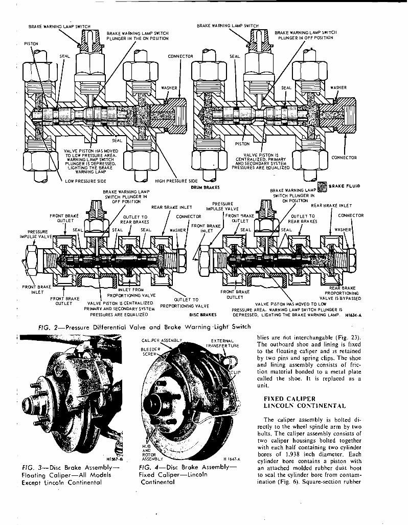
BRAKE WARNlFlC CAMP SWITCH BRAKE WARNING LAMP SWITCH
BRAKE WARNING LAMP SWITCH
WARNING LAMP
LOW PRESSURE SIDE
BRAKE WARNING LAMP
I
FRONT BRAKE FRONT 3RAKE
OUTLET VALVE PISTON IS CENTRALIZED. VALVE PISTON HAS MOVED TO LOW PRIMARY AND SECONDARY SYSTEM
PROPORT'ONING VALVE PRESSURE AREA. WARNING LAMP SWITCH PLUNGER IS
PRESSURES ARE EQUALIZED DISC BRAKES DEPRESSED, LIGHTING THE BRAKE WARNING LAMP. H1634-A
FIG. 2 - P r e s s u r e Differential Valve and Brake Warning -Light' Switch
H 1 saci FIG. 3-Disc Brake Assembly- Floating Caliper-All Models Except Lincoln Continental
FIG. 4-Disc Broke Assembly- Fixed Caliper-Lincoln Continental
blies are riot interchangable ( ~ i g . 23). The outboard shoe and lining is fixed to the floating caliper and is retained by two pins and spring clips. The shoe and lining assembly consists of fric- tion material bonded to a metal plate called the shoe. It is replaced as a unit.
FIXED CALIPER LINCOLN CONTINENTAL
The caliper assembly is bolted di- rectly to the wheel spindle arm by two bolts. The caliper assembly consists of two caliper housings bolted together with each half containing two cylinder bores of 1.938 inch diameter. Each cylinder bore contains a piston with an attached molded rubber dust boot to seal the cylinder bore from contam- ination (Fig. 6). Square-section rubber
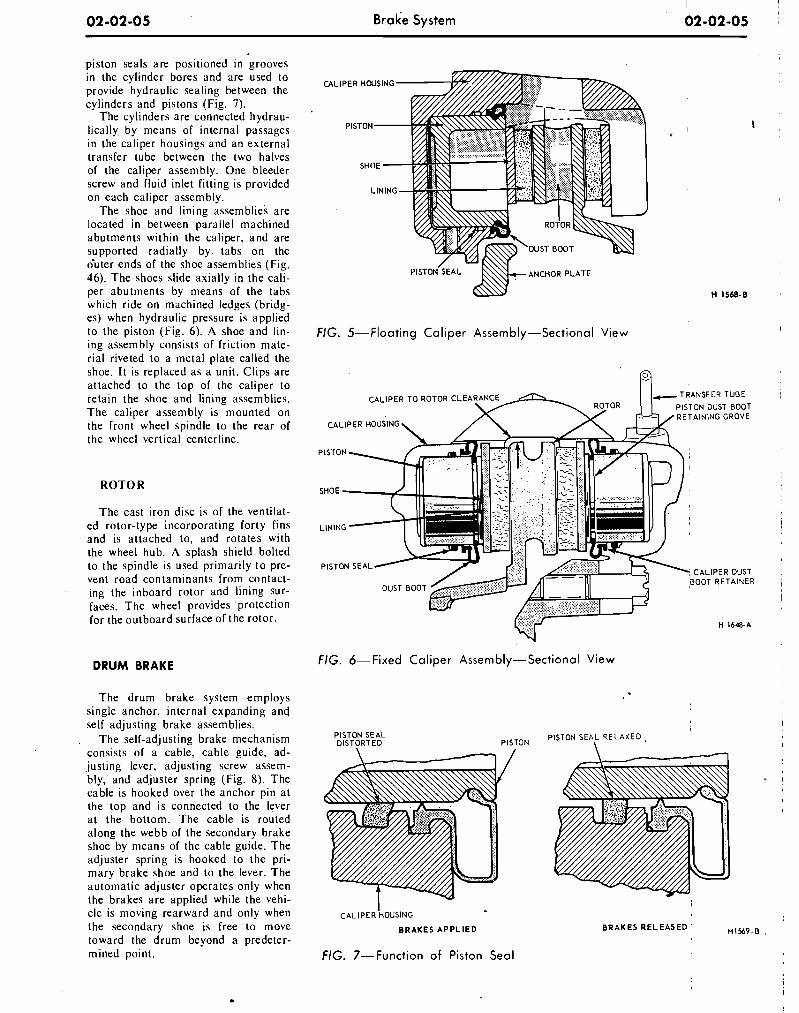
Brake System
piston seals are positioned in grooves in the cylinder bores and are used to provide hydraulic sealing between the cylinders and pistons (Fig. 7).
The cylinders are connected hydrau- lically by means of internal passages in the caliper housings and an external transfer tube between the two halves of the caliper assembly. One bleeder screw and fluid inlet fitting is provided on each caliper assembly.
The shoe and lining assemblies are located in between parallel machined abutments within the caliper, and are supported radially by tabs on the duter ends of the shoe assemblies (Fig. 46). The shoes slide axially in the cali- per abutments by means of the tabs which ride on machined ledges (bridg- es) when hydraulic pressure is applied to the piston (Fig. 6). A shoe and lin- ing assembly consists of friction mate- rial riveted to a metal plate called the shoe. It is replaced as a unit. Clips are attached to the top of the caliper to retain the shoe and lining assemblies. The caliper assembly is mounted on the front wheel spindle to the rear of the wheel vertical centerline.
The cast iron disc is of the ventilat- ed rotor-type incorporating forty fins and is attached to, and rotates with the wheel hub. A splash shield bolted to the spindle is used primarily to pre- vent road contaminants from contact- ing the inboard rotor and lining sur- faces. The wheel provides protection for the outboard surface of the rotor.
DRUM BRAKE
The drum brake system employs single anchor, internal expanding and self adjusting brake assemblies.
The self-adjusting brake mechanism consists of a cable, cable guide, ad- justing lever, adjusting screw assem- bly, and adjuster spring (Fig. 8). The cable is hooked over the anchor pin at the top and is connected to the lever at the bottom. The cable is routed along the webb of the secondary brake shoe by means of the cable guide. The adjuster spring is hooked to the pri- mary brake shoe and to the lever. The automatic adjuster operates only when the brakes are applied while the vehi-
P~STON'~EAL h\\ ANCHOR PLATE
FIG. 5-Floating Cal iper Assembly-Sectional View
R
FIG. 6-Fixed Cal iper Assembly-Sectional View
PISTON SEAL DISTORTED PISTON
PISTON SEAL R E L A X E D ,
cle is moving rea-rward and only when I CALIPER HOUSING
the secondary shoe is free to move B R A K E S APPLIED
toward the drum beyond a predeter- mined point. FIG. 7-Function of Piston Sea l
I BRAKES RELEASED H1569-B
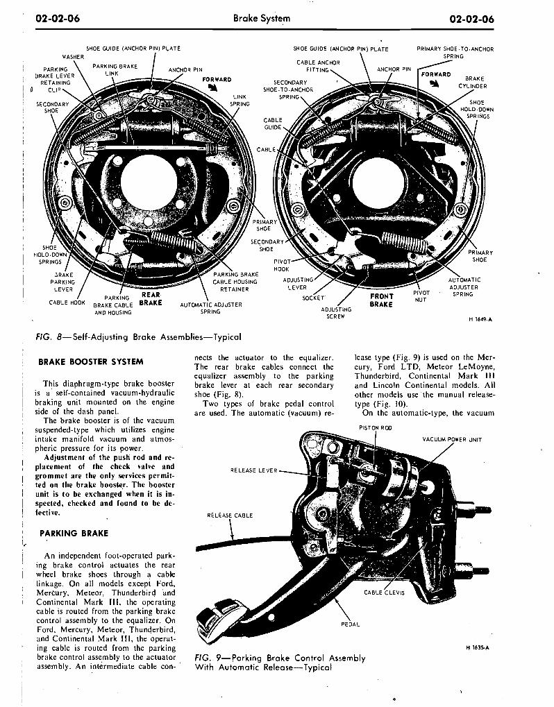
02-02-06 Brake system 02-02-06
SHOE WlDE (ANCHOR PIN) PLATE WASHER I
SHOE WIDE (WCHOP PIN) PLATE P R I M A R Y SHOE .TO.ANCHOR \ SPRING
FIG. 8-Self-Adjusting Brake Assemblies-Typical
BRAKE BOOSTER SYSTEM
This diaphragm-type brake booster is a ' self-contained vacuum-hydraulic braking unit mounted on the engine side of the dash panel.
The brake booster is of the vacuum suspended-type which utilizes engine intake manifold vacuum and atmos- pheric pressure for its power.
Adjustment of the push rod and re- placement of the check valve and grommet are the only services permit- ted on the brake boostqr. The booster unit is to be exchanged when it is in- spected, checked and found to be de- fective.
PARKING BRAKE
An independent foot-operated park- ing brake control actuates the rear wheel brake shoes through a cable linkage. On all models except Ford, Mercury, Meteor, Thunderbird and Continental Mark Ill, the operating cable is routed from the parking brake control assembly to the equalizer. On Ford, Mercury, Meteor, Thunderbird, and Continental Mark I l l , the operat- ing cable is routed from the parking brake control asse,mbly to the actuator assembly. An intermediate cable con-
nects the actuator to the equalizer. lease type (Fig. 9) is used on the Mer- The rear brake cables connect the cury, Ford LTD, Meteor LeMoyne, equalizer assembly to the parking Thunderbird, Continental Mark 111 brake lever at each rear secondary and Lincoln Continental models. All shoe (Fig. 8). other models use the manual release-
Two types of brake pedal control type (Fig. 10). are used. The automatic (vacuum) re- On the automatic-type, the vacuum
FIG.. 9-Parking Brake Control Assembly With Automatic Release-Typical
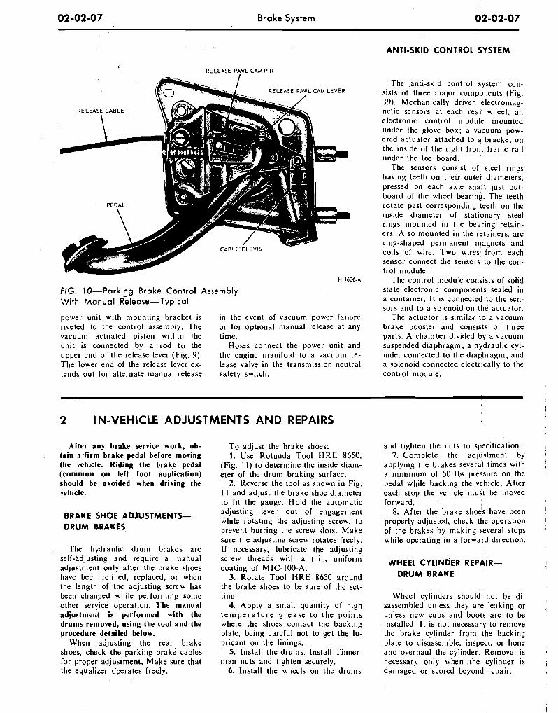
02-02-07 Brake System
ANTI-SKID CONTROL SYSTEM
6' RELEASE PAWL CAM PIN
ti 1636-A
FIG. 10--Parking Brake Control Assembly With Manual ~ l e a s e - ~ ~ ~ i c a l
power unit with mounting bracket is in the event of vacuum power failure riveted to the control assembly. The or for optional manual release at any vacuum actuated piston within the time. unit is connected by a rod to the Hoses connect the power unit and upper end of the release lever (Fig. 9). the engine manifold to a vacuum re- The lower end of the release lever ex- lease valve in the transmission neutral tends out for alternate manual release safety switch.
The .anti-skid control system con- sists of three major components (Fig. 39). Mechanically driven electromag- netic sensors at each rear wheel; an electronic control module mounted under the glove box; a vacuum pow- ered actuator attached to a bracket on the inside of the right front frame rail under the toe board.
The sensors consist of steel rings having teeth on their outer diameters, pressed on each axle shaft just out- board of the wheel bearing. The teeth rotate past corresponding teeth on the inside diameter of stationary steel rings mounted in the bearing retain- ers. Also mounted in the retainers, are ring-shaped permanent magnets and coils of wire. Two wires: from each sensor connect the sensors to the con- trol module.
The control module consists of solid state electronic components sealed in a container. I t is connected to the sen- sors and to a solenoid on the actuator.
The actuator is similar to a vacuum brake booster and consists ol three parts. A chamber divided by a vacuum suspended diaphragm; a hydraulic cyl- inder connected to the diaphragm; and a solenoid connected electrically to the control module.
2 I N-VEHICLE ADJUSTMENTS AND REPAIRS
After any brake service work, ob- tain a firm brake pedal before moving the vehicle. Riding the brake pedal (common on left foot application) should be avoided when driving the vehicle.
BRAKE SHOE ADJUSTMENTS- DRUM BRAKES,
, The hydraulic drum brakes are self-adjusting and require a manual adjustment only after the brake shoes have been relined, replaced, or when the length of the adjusting screw has been changed while performing some other service operation. The manual adjustment is performed with the drums removed, using the tool and the procedure detailed below.
When adjusting the rear brake shoes, check the parking brakd cables for proper adjustment. Make sure that the equalizer operates freely.
To adjust the brake shoes: 1. Use Rotunda Tool H R E 8650,
(Fig. I I) to determine the inside diam- eter of the drum braking surface.
2. Reverse the tool as shown in Fig. I I and adjust the brake shoe diameter to fit the gauge. Hold the automatic adjusting lever out of engagement while rotating the adjusting screw, to prevent burring the screw slots. Make sure the adjusting screw rotates freely. If necessary, lubricate the adjusting screw threads with a thin, uniform coating of MIC- 100-A.
3. Rotate Tool HRE 8650 around the brake shoes to be sure of the set- ting.
4. Apply a small quantity of high t e m p e r a t u r e g r e a s e t o the points where the shoes contact the backing plate, being careful not to get the lu- bricant on the linings.
5. Install the drums. Install Tinner- man nuts and tighten securely.
6. Install the wheels on the drums
and tighten the nuts to specification. , 7. Complete the adjustment by
applying the brakes several times with ; a minimum of 50 Ibs pressure on the pedal while backing the vehicle. After each stop the vehicle must be moved forward.
8. After the brake sho4s have been 1 properly adjusted, check the operation I
of the brakes by making several stops '
while operating in a forward direction. 1 I
WHEEL CYLINDER REPAIR- DRUM BRAKE
Wheel cylinders shouldl not be di- , sassembled unless they are leaklng or , unless new cups and boots are to be installed. It is not necessary to remove the brake cylinder from the backing plate to disassemble, inspect, or hone and overhaul the cylinder. Removal is a
necessary orlly when the 1 cylinder is , damaged or scored beyond repair.
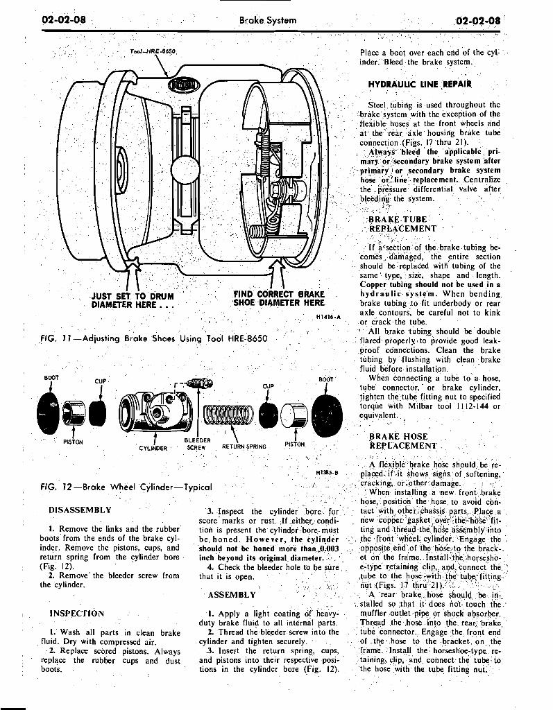
02-02-08 B r a k e S y s t e m 02-02-08
A i Tw/-HR~-8650 Place a boot over each end of the cyl- inder. Bleed the brake system.
HYDRAULIC LINE LREPAIR , .
Steel tubing IS used throughout the brake system with the exception of the flexible hoses at the front wheels and at the' rear axle housing brake tube connection (Figs. 17 thru 21).
Always bleed the applicable pri- mary or secondary brake system after primary or secondary brake system hose or? line replacement. Centralize the pressure differential valve after bleeding the system.
" - r I -
4 - . . B R A K E T U B E R E P L A C E M E N T
I *
I f slction of the brake tubing be- comes , dam'aged, the entire section should be replaced w i d tubing of the same type, size, shape and length. Copper tubing should not be used in a h y d r a u l i c system. When bending brake tubing to fit underbody or rear axle contours; be careful not to kink .or crack,the tube. ' All brake tubing should be double
,FIG. 7 7 -Adjusting Brake Shoes Using Tool HRE-8650 flared properly to provide good leak- proof connections. Clean t h e brake tubing by flushing with clean brake fluid before installation.
When connecting a tube to a hose, tube connector, ' or brake cylinder, tighten the.tube fitting nut to specified torque with Milbar tool 1 1 12-144 or equivalent. ,
B R A K E H O S E R E P L A C E M E N T
A flexlble brake hose should be ;e- H'"5-0 placed- i f +it shows signs of softening,
cracking, or ,other damage. FIG. 72-Brake Wheel Cylinder-Typical When installing a new front brake
hose, position the hose to avoid con- D I S A S S E M B L Y 3. Inspect the cylinder bore for tact with other,,chassis, parts. Place a
score marks or rust. If either condi- new copper 'gasket,over they'hb'se fit- I. Remove the links and the rubber tion is present the cylinder bore must ting and thread the'hoie assembly into
boots from the ends of the brake cyl- be h o n e d . H o w e v e r , the cylinder , therfront wheel cylinder. "Engage the inder. Remove the pistons, cups, and should not be honed more than ,0.003 opposite end .of the hosk: to the brack-. return spring from the cylinder bore inch beyond its original diameter. et on the frame..Install the horsesho- (Fig. 12). 4. Check the bleeder hole to be sure e-type retaining clip,. and connect the '
2. Remove the bleeder screw from that it is open. tube to the hose -with ,the' tube,'fitting the cylinder. a , nut (Figs. 17 thru' 21). s:.
A S S E M B L Y A rear brake ,hose should be in- stalled so ,that it does not touch the
I N S P E C T I O N 1. Apply a light coating of heavy- muffler outlet pipe or shock absorber. duty brake fluid to all internal parts. Thread the .hose into the rear, brake
1. Wash all parts in clean brake 2. Thread the bleeder screw into the tube connector. Engage the front end fluid. Dry with compressed air. cylinder and tighten securely. of t h ~ hose to the bracket on the
2. Replace scored pistons. Always 3. Insert the return spring, cups, frame. Install the horseshoe-type re- replace the rubber cups and dust and pistons into their respective posi- taining. clip, and connect the tube to boots. tions in the cylinder bore (Fig. 12). the hose with the tube fitting nut.
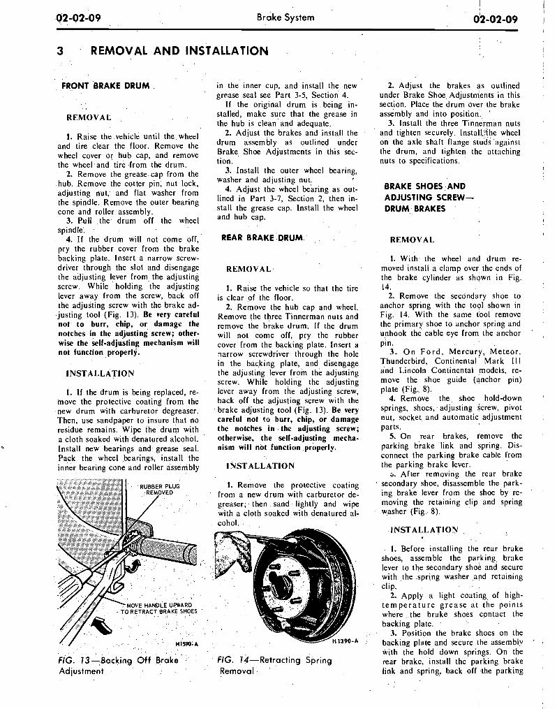
02 -02-09 Brake System
3 REMOVAL A N D INSTALLATION
FRONT BRAKE D R U M in the inner cup, and ~nstall the new grease seal see Part 3-5, Section 4.
If the original drum is being in-
REMOVAL stalled, make sure that the grease in the hub is clean and adequate.
1. Raise the vehicle until the wheel 2. Adjust the brakes and install the
and tire clear the floor. Remove the drum assembly as out'ined under wheel cover or hub cap, and remove Brake Shoe Adjustments in this sec-
the wheel and tire from the drum. 2. Remove the grease cap from the
hub. Remove the cotter pin, nut lock, adjusting nut, and flat washer from 'the spindle. Remove the outer bearing cone and roller assembly.
3. Pull the drum off the wheel spindle: . '
4. If the drum will not come off, pry the rubber cover from the brake backing plate. Insert a narrow screw- driver through the slot and disengage the adjusting lever from, the adjusting screw. While holding the adjusting lever away from the screw, back off the adjusting screw with the brake ad-
.justing tool (Fig. 13). Be very careful not to burr, chip, or damage the notches in the adjusting screw; other- wise the self-adjusting mechanism will not function properly.
INSTALLATION
1. If the drum is being replaced, re- move the protective coating from the new drum with carburetor degreaser. Then, use sandpaper to insure that no residue remains. Wipe the drum with a cloth soaked with denatured alcohol. Install new bearings and grease seal. Pack the wheel bearings, install the inner bearing cone and roller assembly
aon. 3. Install the outer wheel bearing,
washer and adjusting nut, #
4. Adjust the wheel bearing as out- lined in Part 3-7, Section 2, then in- stall the grease cap. Install the wheel .and hub cap.
REAR BRAKE :DRUM
REMOVAL
1. Raise the vehicle so that the tire is clear of the floor.
2. Remove the hub cap and wheel. Remove the three Tinnerman nuts and remove the brake drum:' If the drum will not ,come off, pry the rubber cover from the backing plate. Insert a narrow screwdriver through the hole in the backing plate, and disengage the adjusting lever from the adjusting screw. While holding the adjusting lever away from, the adjusting screw, back off the adjusting screw with the brake adjusting tool (Fig. 13). Be very careful not to burr, chip, or damage the notches in .the adjusting screw; otherwise, the self-adjusting mecha- nism will not function properly.
INSTALLATION
1. Remove the protective coating from a new drum with carburetor de- greaser; then sand lightly and wipe with a cloth soaked with denatured al- cohol.
FIG. 13-Backing Off Brake FIG. 14-Retracting Spring Adjustment Removal
2. Adjust the brakes as outlined under Brake Shoe ~djustm'ents in this section. Place the drum over the brake assembly and into pos~tion. '
3. Install the three Tinnerman nuts and t~ghten securely. Install !the wheel on the axle shaft flange studs against the drum, and t~ghten the attaching nuts to spec~flcat~ons.
I
BRAKE SHOES A N D ADJUSTING SCREW- D R U M BRAKES
REMOVAL
1. With the wheel and drum re- moved install a clamp over the ends of the brake cylinder as shown in Fig. 14.
2. Remove the secondary shoe to anchor spring with the tool shown in Fig. 14. With the same tbol remove the primary shoe to anchor spring and unhook the cable eye from the anchor '
pin. 3. O n F o r d , Mercury, Meteor,
Thunderbird, Continental Mark 11 I and Lincoln Continental models, re- move the shoe guide (anchor pin) plate (Fig. 8).
4. Remove the shoe hold-down springs, shoes, adjusting screw, pivot nut, socket and automatic adjustment parts.
5. On rear brakes, remove the parking biake 'link and spring. Dis- connect the parking brake cable from the parking brake lever. s. After removing the rear brake
secondary shoe, disassemble the park- ing brake lever from the shoe by re- moving the retaining clip, and spring w,asher (Fig.- 8).
INSTALLATION . . .
. - 1. Before installing the rear brake shoes, assemble the park.ing, brake lever to the secondary shoe and secure with the .spring washer ,and retaining clip. . . . # ,
2. Apply a light coating, of high- t e m p e r a t u r e g r e a s e a t ' t h e points where ,.the brake shoes .contact the backing plate.
3. Position the brake shoes on the backingplate and secure the assembly with the hold down springs. On the rear brake, install the parking brake link and spring, back off .the parking
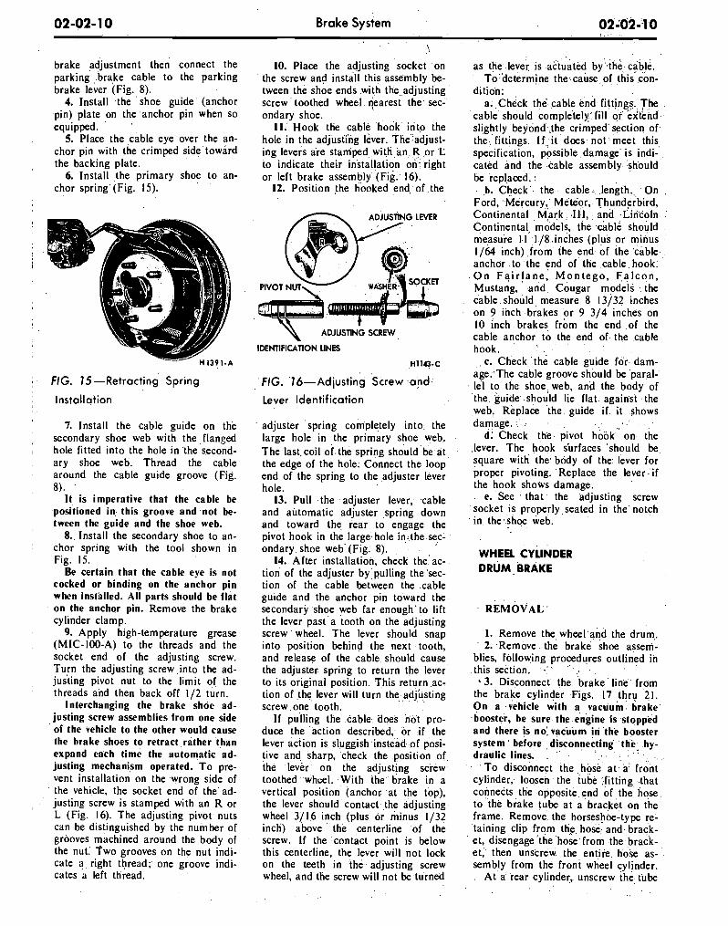
Brake System
brake ?djustment then connect the parking ,.brake cable to the parking brake lever (Fig. 8).
4. Install the 'shoe guide' (anchor .pin) plate on the.anchor pin when so equipped.
5. Place the ,cable eye over the an- chor pin with the crimped side'toward the backing plate.
6. Install the primary shoe to an- . . chor spring' (Fig. 15).
I . FIG. 15-Retracting Spring
Installation
7. Install the cable guide on th.e secondary shoe web with the ,flanged hole fitted into the hole in the second- arv shoe web. Thread the cable arbund the cable guide groove (Fig. 8). '
It. is imperative that the cable be positioned i n this groove and not be- tween the guide and the shoe web.
8.. Install the secondary shoe to an- chor spring with the tool shown in Fig. 15.
Be certain that the cable eye is not cocked or binding on the anchor pin when inst'alled. All parts should be flat on the anchor p i n . ~ ~ e m o v e the brake cylinder clamp.
9. Apply high-temperature grease (MIC-100-A) to the threads' and the socket end of the adjusting screw. Turn the adjusting screw,into the ad- justing pivot nut to the limit of the threads and then back off 112 turn.
Interchanging the brake shoe ad- justing screw assemblies from one side of the vehicle to the other would cause the brake shoes to retract,rather than expand each time the automatic ad- justing mechanism operated. T o pre- vent installation on the wrong side of the vehicle, the socket end of the'ad- justing screw is stamped with an R or L (Fig. 16). The adjusting pivot. nuts can be distinguished by .the number of grooves machined around the body of the nut: Two grooves on the nut indi- cate a . right thread; one groove indi- cates a left tliread.
\
10. Place the adjusting socket on the screw and install this assembly be- tween the shoe ends with the adjusting screw toothed wheel nearest the sec- ondary shoe.
11. Hook the cable hook into the hole in the adjustihg lever. The adjust- ing levers are stamped with an R or L to indicate their installation on- right or left brake assembly (Fig. 16).
12. Position the hooked end of the
ADJUS~~NG L M R
ADJUSTING SCREW
IDENTIFICATION LINES
FIG. 16-Adjusting Screw a n d
Lever Identification
adjuster spring completely into, the large hole in the primary shoe web. The last coil of.the spring should be at the edge of the hole. Connect the loop end of the spring to the adjuster lever hole.
13. Pull the adjuster lever, cable and automatic adjuster spring down and toward the rear to engage the pivot hook in the large hole insthe sec- ondary shoe web (Fig. 8).
14. After installation, check the ac- tion of the adjuster by pulling the'sec- tion of the cable between the cable g u ~ d e and the anchor pin toward the secondary shoe web far enough'to lift the lever past a tooth on the adjusting screw wheel. The lever should snap into position behind the next tooth, and release of the cable should cause the adjuster spring to return the lever to its original position. This return ac- tion of the lever will turn the adjusting screw one tooth.
If pulling the cable does not pro- duce the action described, or if the lever action is sluggish instead of posi- tive and sharp, check the position of the lever on the adjusting screw toothed wheel. With the brake in a vertical position (anchor at the top), the lever should contact the adjusting wheel 3/16 inch (plus or minus 1/32 inch) above the centerline of the screw. If the contact point is below this centerline, the lever will not lock on the teeth in the adjusting screw wheel, and the screw will not be turned
as the lever is actuated by the cable. To determine the cause of this con-
dition: a. Check the cable end fittings. The
cable should completely,~fill or extend slightly beyond the crimped section of the fittings. I f , i t does not meet this specification, possible damage is indi- cated and the cable assembly should be replaced.
b. Check the cable length. On Ford, Mercury, Meteor, Thunderbird, Continental Mark 111, and Lincoln Continental. models, the cable should measure l l 118 inches (plus or minus 1/64 inch) from the end of the cable anchor to the end of the cable hook. O n F a i r l a n e , M o n t e g o , F a l c o n , Mustang, and Cougar models the cable should measure 8 13/32 inches on 9 inch brakes or 9 314 inches on 10 inch brakes from the end of the cable anchor to the end of the cable hook.
c. Check the cable g u ~ d e for dam- age. The cable groove should be paral- lel to the shoe web, and the body of the guide should lie flat against the web. Replace the guide i f it shows damage.
d. Check the pivot hook on the lever. The hook s'urfaces should be square with the'body of the lever for proper pivoting. Replace the lever if the hook shows damage.
e. See that the adjusting screw socket is properly seated in the notch in the shoe web.
WHEEL CYLINDER DRUM BRAKE
1. Remove the wheel and the drum. 2. Remove the brake shoe assem-
blies, Following procedures outlined in this section. . %3. Disconnect the brake line from
the brake cylinder Figs. 17 thru 21. On a vehicle with a vacuum brake booster, be sure the engine is stopped and there is no' vacuum in the booster system before disconnecting the hy- draulic lines.
To disconnect the hose a t a front cylinder, loosen the tube fitting that connects the opposite end of the hose to the brake tube a t a bracket on the frame. Remove the horseshoe-type re- taining clip from the hose and brack- et, disengage the hose from the brack- et, then unscrew the e n t ~ r e hose as- sembly from the front wheel cylinder.
At a rear cylinder, unscrew the tube
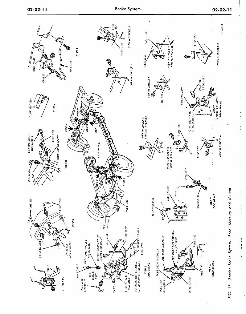
EX
IST
ING
BO
LT
A
ND
WAS
HER
T
Ud
E 2
267.
2268
+ \.
HO
SE \
2A44
8
VlE
W T
TU
dE
226
3
PR
ES
SU
RE
IM
PU
LSE
OP
OR
TlO
NlN
G V
AL
VE
D
AS
H P
AN
EL
/ V
IEW
IN
CIR
CLE
J
I P
RE
SS
UR
E D
IFF
ER
EN
TIA
L
VA
LVE
26
257.
D A
SS
EM
BLY
T
UB
E 2
265
@
VIE
W I
N C
IRC
LE N
V
IEW
Z
TY
Pl
_ - --.
DIS
C B
RA
KE
TUO
E 2
253
2264
TU
BE
282
53 A
SS
EM
BLY
T
UB
E 2
2M
/-T
UBE
2A04
0 A
SS
EM
BLY
PR
ES
SU
RE
DIF
FE
RE
NT
IAL
/ T
UB
E 2
265 31
CA
L 2
PLA
CE
S
VlE
W I
N C
IRC
LE
W
TU
8E
27.6
5
VlE
W I
N C
IRC
LE
X
TY
PIC
AL
3 P
LAC
ES
. h
VlE
W I
N C
IRC
LE
V /
TY
PIC
AL
5 P
LAC
ES
a 22
63-2
264
ASSY
.
C9A
A-2
149
m /
&
i
C7A
A-2
082-
A R
.H.
C7A
A-2
A05
6-L.
H.
TUB
E
2565
i 11
2 R
EQ
UIR
EP
FIG
. 17
---S
ervi
ce
Bra
ke
Sys
tem
-For
d,
Me
rcu
ry a
nd M
ete
or
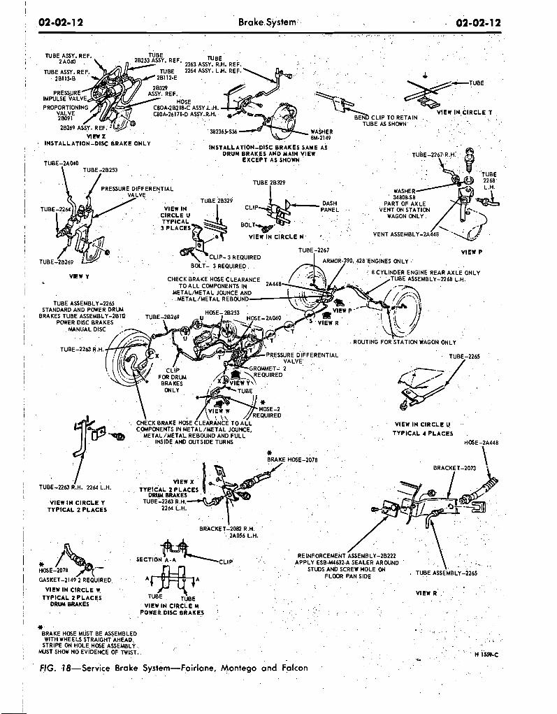
02 -02- 1 2 Brake System 02-02-1 2 I
. '7 TUBE-2263 R.H. 2264 L.H.
VlEW I N CIRCLE Y TYPICAL 2 PLACES
. .
GASKET-2149 2 REQUIRED,
VlEW IN CIRCLE W TYPICAL 2 PLACES
D R W BRAKES VlEW I N CIRCLE M POWER DISC BRAKES
" BRAKE HOSE MUST BE ASSEMBLED WITH WHEELS STRAIGHT AHEAD.,
STRIPE ON HOLE HOSE ASSEMBLY MUST SHOW NO EVIDENCE OFTWLST. - FIG. 18-Service Brake System-Fairlane, Montego and Falcon
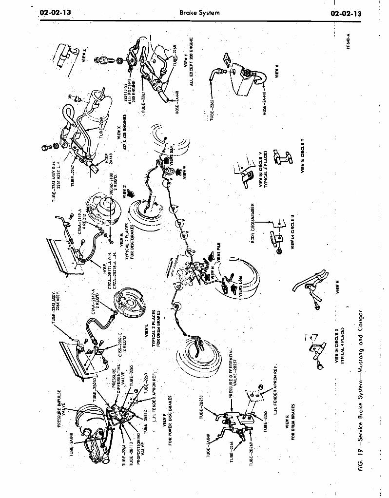
\ L.
H.
FEN
DE
R A
PRO
N R
EF
. n
Ew
w
VIE
* R
FO
R D
RUM
BR
AK
ES
VIEW
IN
UR
CL
E U
VIE
W IN
aR
aE
T
. .
VIEW
IN c
lRa
E s
--
TYP
ICA
L 4
PLA
CE
S
FIG
. 1
9-S
erv
ice
B
rake
Sys
tem
-Mu
stan
g
and
Co
ug
ar
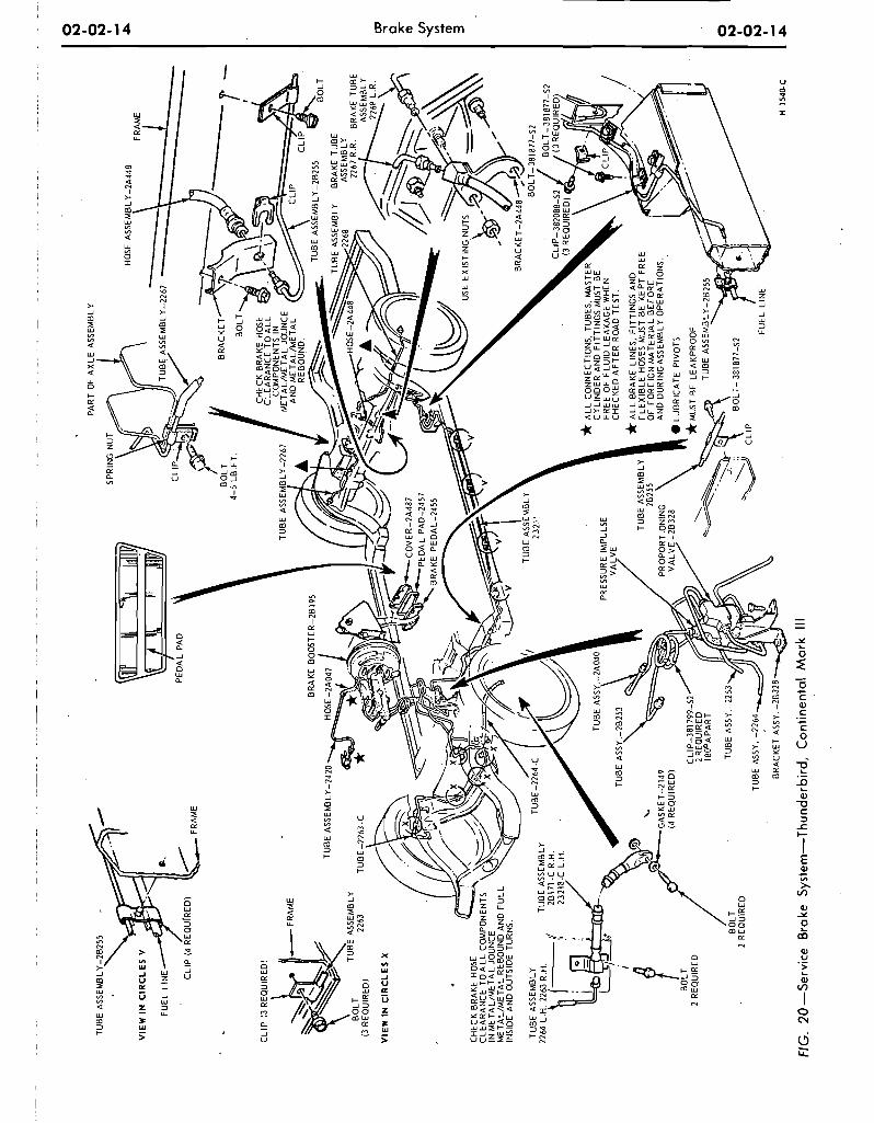
FIG
. 20
-Ser
vice
B
rake
Sys
tem
-Th
un
der
bir
d,
Co
nti
nen
tal
Ma
rk I
ll
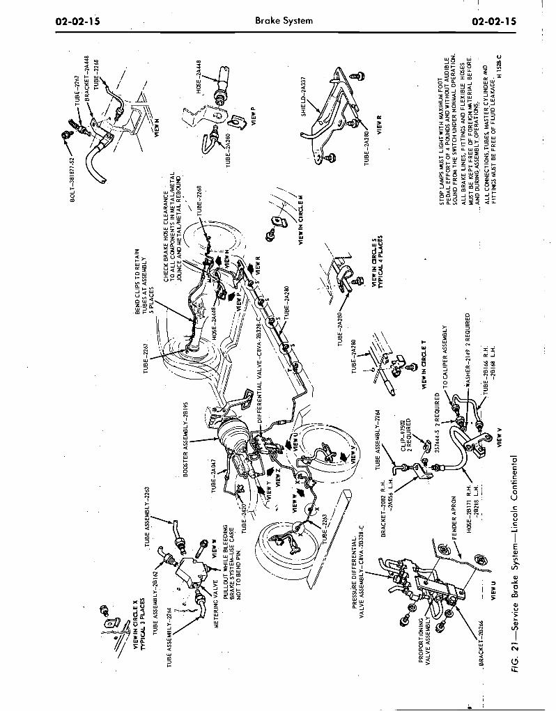
FIG
. 2
1 -S
ervi
ce
Bra
ke S
yste
m-L
inco
ln
Co
nti
nen
tal
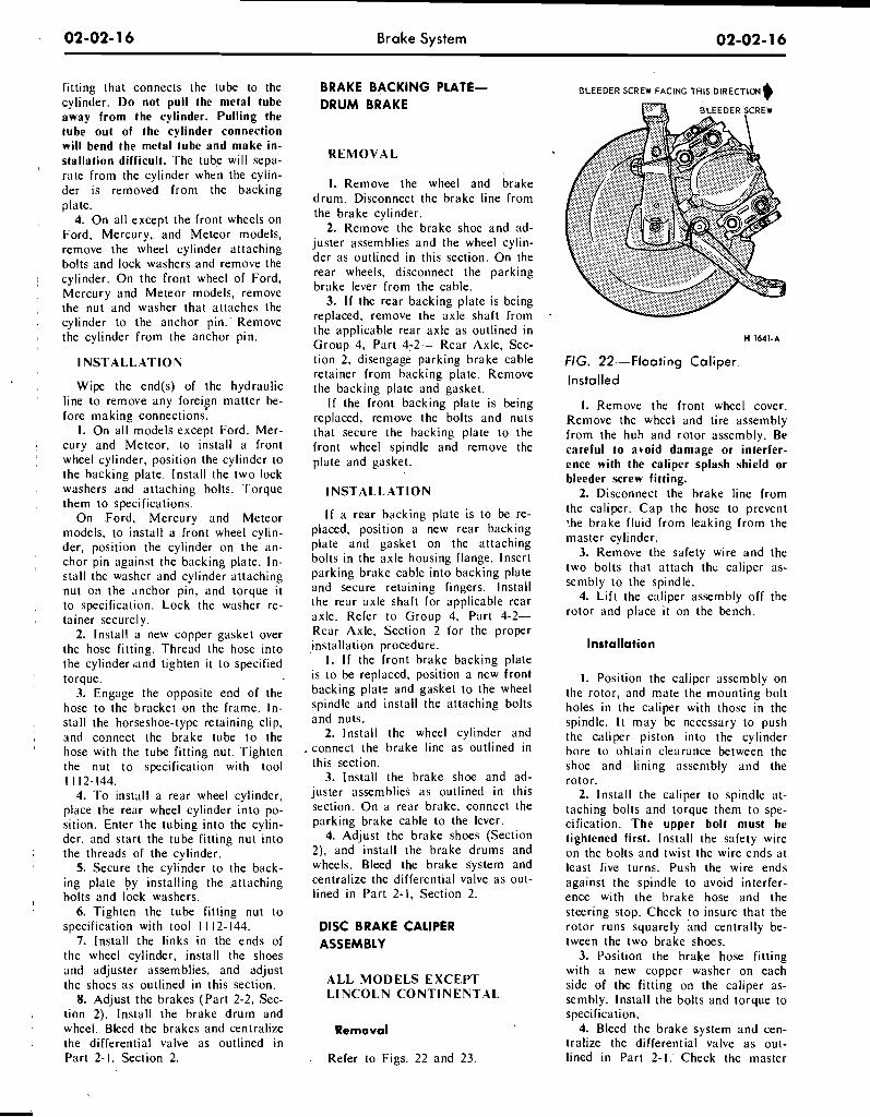
fitting that connects the tube to the cylinder. Do not pull the metal tube away from the cylinder. Pulling the tube out of the cylinder connection will bend the metal tube and make in- stallation difficult. The tube will sepa- rate from the cylinder when the cylin- der is removed from the backing plate.
4. On all except the front wheels on Ford, Mercury, and Meteor models, remove the wheel cylinder attaching bolts and lock washers and remove the cylinder. On the front wheel of Ford, Mercury and Meteor models, remove the nut and washer that attaches the cylinder to the anchor pin. Remove the cylinder from the anchor pin.
l NSTALLATION
Wipe the end(s) of the hydraulic line to remove any foreign matter be- fore making connections.
1. On all models except Ford, Mer- cury and Meteor, to install a front wheel cylinder, position the cylinder to the backing plate. lnstall the two lock washers and attaching bolts. Torque them to specifications.
On Ford, Mercury and Meteor models, to install a front wheel cylin- der, position the cylinder on the an- chor pin against the backing plate. In- stall the washer and cylinder attaching nut on the anchor pin, and torque it to specification. Lock the washer re- tainer securely.
2. Install a new copper gasket over the hose fitting. Thread the hose into the cylinder 'and tighten it to specified torque.
3. Engage the opposite end of the hose to the bracket on the frame. I n - stall the horseshoe-type retaining clip, and connect the brake tube to the hose with the tube fitting nut. Tighten the nut to specification with tool I 1 12- 144.
4. To install a rear wheel cylinder, place the rear wheel cylinder into po- sition. Enter the tubing into the cylin- der, and start the tube fitting nut into the threads of the cylinder.
5. Secure the cylinder to the back- ing plate by installing the .attaching bolts and lock washers.
6. Tighten the tube fitting nut to specification with tool 1 1 12-144.
'
7. Install the links in the ends of the wheel cylinder, install the shoes and adjuster assemblies, and adjust the shoes as outlined in this section.
8. Adjust the brakes (Part 2-2, Sec- tion 2). Install the brake drum and wheel. Bleed the brakes and centralize the differential valve as outlined in Part 2-1. Section 2.
Brake System
BRAKE BACKING PLATE- BLEEDER SCREW FACING THIS DIRECTION
DRUM BRAKE
REMOVAL
1. Remove the wheel and brake drum. Disconnect the brake line from the brake cylinder.
2. Remove the brake shoe and ad- juster assemblies and the wheel cylin- der as outlined in this section. On the rear wheels, disconnect the parking brake lever from the cable.
3. I f the rear backing plate is being replaced, remove the axle shaft from the applicable rear axle as outlined in Group 4, Part 4-2- Rear Axle, Sec- tion 2, disengage parking brake cable retainer from backing plate. Remove the backing plate and gasket.
I f the front backing plate is being replaced, remove the bolts and nuts that secure the backing plate to the front wheel spindle and remove the plate and gasket.
INSTALLATION
I f a rear backing plate is to be re- placed, position a new rear backing plate and gasket on the attaching bolts in the axle housing flange. Insert parking brake cable into backing plate and secure retaining fingers. Install the rear axle shaft for applicable rear axle. Refer to Group 4, Part 4-2- Rear Axle, Section 2 for the proper installation procedure.
1. I f the front brake backing plate is to be replaced, position a new front backing plats and gasket to the wheel spindle and install the attaching bolts and nuts.
2. Install the wheel cylinder and connect the brake line as outlined in this section.
3. Install the brake shoe and ad- juster assemblies as outlined in, this section. On a rear brake, connect the parking brake cable to the lever.
4. Adjust the brake shoes (Section 2), and install the brake drums and wheels. Bleed the brake system and centralize the differential valve as out- lined in Part 2-1. Section 2.
DISC BRAKE CALIPER ASSEMBLY
ALL MODELS EXCEPT LINCOLN CONTINENTAL
Removal
. Refer to Figs. 22 and 23.
FIG. 22.-Floating Cal iper .
Installed
1. Remove the front wheel cover. Remove the wheel and tire assembly from the hub and rotor assembly. Be careful to avoid damage or interfer- ence with the caliper splash shield or bleeder screw fitting.
2. Disconnect the brake line from the caliper. Cap the hose to prevent '.he brake fluid from leaking from the master cylinder.
3. Remove the safety wire and the two bolts that attach thc caliper as- sembly to the spindle.
4. Lift the caliper assembly off the rotor and place it on the bench.
Installation
I. Position the caliper assembly on the rotor, and mate the mounting bolt holes in the caliper with those in the spindle. It may be necessary to push the caliper piston into the cylinder bore to obtain clearance between the shoe and lining assembly and the rotor.
2. Install the caliper to spindle at- taching bolts and torque them to spe- cification. The upper bolt must be tightened first. Install the safety wire on the bolts and twist the wire ends at least five turns. Push the wire ends against the spindle to avoid interfer- ence with the brake hose and the steering stop. Check to insure that the rotor runs squarely and centrally be- tween the two brake shoes.
3. Position the brake hose fitting with a new copper washer on each side of the fitting on the caliper as- sembly. Install the bolts and torque to specification.
4. Bleed the brake system and cen- tralize the differential valve as out- lined in Part 2-1. Check the master
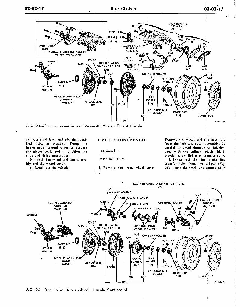
02-02- 1 7 Brake System
CONE AND ROLLER
3106-L.H.
ROTOR S P W H SHlEL
2KOO5-L.H.
FIG. 2 3 - - ~ i s c B r a k e - D i s a s s e m b l e d - A l l M o d e l s Except Lincoln
cylinder fluid level and add the speci- fied fluid, as required. Pump the brake pedal several times to actuate the piston seals and to position the shoe and lining assemblies.
5. Install the wheel and tire assem- bly and the wheel cover.
6. Road test the vehicle.
I
L I N C O L N CONTINENTAL Remove the wheel and tire assembly from the hub and rotor assembly. Be careful to avoid damage ;or intcrfcr- 1 Removal ence with the caliper splash shield, bleeder screw fitting or transfer tube.
Refer to Fig. 24. 2. Disconnect the steel, brake line transfer tube from the caliper (Fig.
I. Remove the front wheel cover. 21). Leave the steel tube donnected to ,
CALl PER PARTS -2B120-R.H. -20121-L.H. CALl PER PARTS -2B120-R.H. -20121-L.H.
CALIPER ASSEMBLY '20118-R.H.
CONE AND ROLLER
3106-L.H.
ROTOR SPLASH SHIELD
2KOO5-L.H.
FIG. 24 - D i s c Brake D i s a s s e m b l e d - L i n c o l n Continental
{INBOARD HOUSING
/ P ISTI34 SEALS 1 4 \ -181 1 5 CLIP
SPINDLE
ASSEMBLIES -2018 2196
CONE AND ROLLER
2K004-R.H. GREASE SEAL 2KOO5-L.H.
I
' H 1650
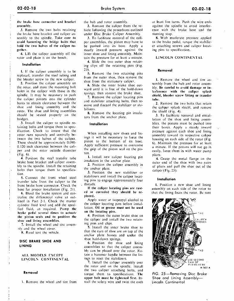
Brake System
the brake hose connector and bracket assenibly.
3. Remove the two bolts retaining the broke hose bracket and calliper as- senibly to the spindle. Take care to avoid loosening the bridge I)olts that hold the two halves of the caliper to- gether.
4. Lift the caliper assembly off the rotor and place it on the bench.
Installation
1. I f the caliper assenibly is to be replaced, transfer the steel tubing and the bleeder screw to the new caliper.
2. Position the caliper assenibly on the rotor, and mate the niounting bolt holes in the caliper with those in the spindle. It niap bc necessary to push the caliper pistons into the cylinder bores to obtain clcarance bctween the shoe and lining assembly and the rotor. The shoe and lining assemblies should be seated properly on the bridges.
3. Install the caliper to spindle re- taining bolts and torque them to spec- ification. Check to insure that the rotor runs squarely and centr;~lly be- tween the two halves of the caliper. These should be approximately 0.090- 0.120 inch clearance between the cali- per and the rotor outside diameter (Fig. 6).
4. Position the steel transfer tube brake hose bracket and caliper asseni- bly to the spindle. Install the retaining bolts then torque them to specifica- tion.
5. Connect the front ' wheel steel transfer tube froni the caliper to the front brake hose connector. Check the hose for proper installation (Fig. 21).
6. Bleed the brake systcni and cen- tralize the dil'fercntial valve a s out- lined in Part 2-1. Check the master cylindcr fluid level and add the speci- fied fluid, a s required. Pump the hrake pedal several times to actuate the piston seals and to position the shoe and lininl: assemblies.
7. Install the wheel and tire assem- bly and the wheel cover.
8. Road test the vehicle.
DISC BRAKE SHOE AND LINING
'Al-I, MODEI,S EXCEPT
i 1.INCOLN C O N T I N E N T A L
Removal I
1. Reniove the wheel and tire from
the hub and rotor assembly. 2. Remove the caliper froni the ve-
hicle following the procedures outlined under Disc Brake Caliper Assembly.
3. T o facilitate removal of the cali- per asseniblies, the piston may have to be pushed into its bore. Apply a steady inward pressure against the inner shoe and lining assembly. Main- tain the pressure for a t least a minute.
4. Slide the two outer shoe retain- ing clips off the retaining pins (Fig. 23).
5. Remove the two retaining pins from the outer shoe, then remove the shoe from the stationary caliper.
6. Slide the inner brake shoe out- ward until it is free of the hold-down springs, then remove the brake shoe.
7. Remove the caliper locating pins and stabilizer attaching bolts, then re- move and discard the stabilizer or sta- bilizers.
8. Remove the locating pin insula- tors from the anchor plate.
Installation
When installing new shoes and lin- ings it will be necessary to force the piston to the bottom of its bore. Apply sufficient pressure to overcome the grip of the piston seal on the pis- ton.
I. Install new caliper locating pin insulators in the anchor plate.
2. Position the caliper assembly in the anchor plate.
3. Position the new stabilizer or stabilizers and install the caliper locat- ing pins to engage approxiniately four threads.
I f the caliper locating pins are rust- ed or corroded they should be re- placed.
Apply water or isopropyl alcohol to the caliper locating pins before instal- lation. Oil or grease must not be used on the locating pins.
4. Position the outer brake shoe on the caliper and install the two retain- ing pins and clips.
5. Install the inner brake shoe so that the ears of shoe are on top of the anchor plate bosses and under the shoe hold-down springs.
6. Position the shoe and lining assemblies so that the caliper assem- bly can be placed over the rotor. Ro- tate a hammer handle between the lin- ings to reset the stabilizers.
7. lnstall the caliper assembly over the rotor and on the spindle. Install the two caliper attaching bolts, and torque them to specifications. The upper bolt must be tightened first. In- stall the safety wire and twist the ends
a t least five turns. Push the wire ends against the spindle to avoid interfer- ence with the brake hose and the steering stop.
8. With moderate pressure applied to the brake pedal, Lorque the stahiliz- er attaching screws and caliper locat- ing pins to specification.
L INCOLN C O N T I NENI 'AL
Remova l
1. Remove the wheel and tire as- sembly from the hub and rotor assem- bly. Be careful to avoid damage or in- terference with the caliper splash shield, bleeder screw fitting or transfer tube.
2. Remove the two bolts that retain the caliper splash shield, and remove the shield (Fig. 4).
3. T o facilitate removal and instal- lation of the shoe and lining asseni- blies, the pistons must be pushed into their bores. Apply a steady inward . pressure against each shoe and lining assembly toward its respective caliper housing on each side of the rotor (Fig. 6). Maintain the pressure for a t least a minute. I f the pistons will not go in easily, force them in with water pump pliers.
4. Grasp the metal flange on the outer end of the shoe with two pairs of pliers and pull the shoe out of the caliper (Fig. 25).
Installation
I. Position a new shoe and lining assembly on each side of the rotor so that the lining faces the rotor. Be sure
FIG. 25--Removing Disc Brake S h o e a n d Lining Assembly- Lincoln Con t inen ta l
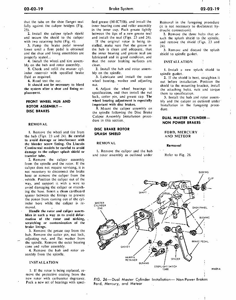
that the tabs on the shoe flanges seat fully against the caliper bridges (Fig. 25).
2. Install the caliper splash shield and secure the shield to the caliper with two retaining bolts (Fig. 4).
3. Pump the brake pedal several times until a firm pedal is obtained and the shoe and lining assemblies are properly seated..
4. Install the wheel and tire assem- bly on the hub and rotor assembly.
5. Check and refill the master cyl- inder reservoir with specified brake fluid as required.
6. Road test the car. I t should not be necessary to bleed
the system after a shoe and lining re- placement.
FRONT WHEEL H U B A N D ROTOR ASSEMBLY - DlSC BRAKES
R E M O V A L
1. Remove the wheel and tire from the hub (Figs. 23 and 24). Be careful to avoid damage or interference with the bleeder screw fitting. O n Lincoln Continental models be careful to avoid damage to the caliper splash shield or transfer tube.
2. Remove the caliper assembly from the spindle and the rotor. If the caliper does not require servicing, it is not necessary to disconnect the brake hose or remove the caliper from the vehicle. Position the caliper out of the way, and support it with a wire to avoid damaging the caliper or stretch- ing' the hose. Insert a clean cardboard spacer between the linings to prevent the piston from coming out of the cyl- inder bore while the caliper is re- m oved .
Handle the rotor and caliper assem- blies in such a way as to avoid defor- mation of the rotor and nicking, scratching or contamination of the brake linings.
3. Remove the grease cap from the hub. Remove the cotter pin, nut lock,
0. adjusting nut, and flat washer from the spindle. Remove the outer bearing cone and roller assembly.
4. Remove the hub and rotor as- sembly from the spindle.
I N S T A L L A T I O N
1. If the rotor is being replaced, re- move the protective coating from the new rotor with carburetor degreaser. Pack a new set of bearings with speci-
Brake System 02-02- 19
fied grease (M-IC75B), and install the inner bearing cone and roller assembly in the inner cup: Pack grease lightly between the lips of a .new grease seal and install the seal (Figs. 23 and 24).
If the original rotor is being in- stalled, make sure that the grease in the hub is clean and adequate, that the inner bearing and grease seal are lubricated and in good condition, and that the rotor braking surfaces are clean.
2. Install the hub and rotor assem- bly on the spindle.
3. Lubricate and install the outer wheel bearing, washer and adjusting nut.
4. Adjust the wheel bearings to specification, and then install the nut lock, cotter pin, and grease cap. The wheel bearing adjustment is especially important with disc brakes.
5. Mount the caliper assembly on the spindle following the Disc Brake Caliper Assembly Installation proce- dure in this section.
DlSC BRAKE ROTOR SPLASH SHIELD
Reinoval in the roregoing procedure (it is not necessary to discbnnect hy- draulic connections).
2. Remove the three bo!ts that at- tach the splash shield to the spindle, and remove the shield (Figs. 23 and 24).
3. Remove and discard 'the splash shield to spindlc gasket.
I N S T A L L A T I O N \
1. Install a new splash shield to spindle gasket.
2. If the shield is bent, straighten it out before installation. Position the shield to the mounting bracket, install the attaching bolts, nuts and torque them to specification.
3. Install the hub and rotor assern- bly and the callper as outlined under Installation in the foregoing proce- dure.
DUAL MASTER CYLINDER- NON POWER BRAKES
F O R D , M E R C U R Y A N D M E T E O R
R E M O V A L Remova l
1. Remove the caliper and the hub and rotor assembly as outlined under Refer to Fig. 26.
BUSYING
/
BUSHING / STOPLIGHT SWITCH
13480
FIG. 26-Dual M a s t e r Cylinder Installation- Non Power Brakes Ford, Mercury, a n d Meteor
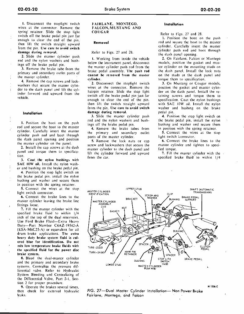
Brake System
I. Disconnect the stoplight switch wires a t the connector. Remove the spring retainer. Slide the stop light switch off the brake pedal pin just far enough to clear the end of the pin, then lift the switch straight upward from the pin. Use care to avoid switch damage during removal.
2. Slide the master cylinder push rod and the nylon washers and bush- ings off the brake pedal pin.
3. Remove the brake tube from the primary and secondary outlet ports of the master cylinder.
4. Remove the cap screws and lock- washers that secure the master cylin- der to the dash panel and lift the cyl- inder forward and upward from the vehicle.
Installat ion
I. Position the boot on the push rod and secure the boot t o the master cylinder. Carefully insert the master cylinder push rod and boot through the dash panel opening and position the master cylinder on the panel.
2. Install the cap screws a t the dash panel and torque them t o specifica- tion.
3. Coat. the nylon bushings with S A E IOW oil. Install the nylon wash- e r and bushing on the brake pedal pin.
4. Position the stop light switch on the brake pedal pin, install the nylon bushing and washer and secure them in position with the spring retainer.
5. Connect the wires a t the stop light switch connector.
6. Connect the brake lines t o the master cylinder leaving the brake line fittings loose.
7. Fill the master cylinder with the specified brake fluid to within 114 inch of the top of the dual reservoirs. Use Ford Brake Fluid-Extra Heavy Duty-Part Number C6AZ-19542-A (ESA-MGC25-A) or equivalent for all drum brake applications. The extra heavy duty brake system fluid is col- ored blue for identification. D o not mix low temperature brake fluids with the specified fluid for the power disc brake system.
8. Bleed the dual-master cylinder and the primary and secondary brake systems. Centralize the pressure dif- ferential valve. Refer to Hydraulic System Bleeding and Centralizing of the Differential Valve, Part .2-I, Sec- tion 2 for proper procedure.
9. Operate the brakes several times, then check for external hydraulic leaks.
F A I R L A N E , M O N T E G O , F A L C O N , M U S T A N G A N D C O U G A R
Remova l
Refer to Figs. 27 and 28.
I. Working from inside the vehicle below the instrument panel, disconnect the master cylinder push rod from the brake pedal assembly. The push rod cannot be remobed from the master cylinder.
2. Disconnect the stoplight switch wires a t the connector. Remove the hairpin retainer. Slide the stop light switch off the brake pedal pin just far enough t o clear the end of the pin, then lift the switch straight upward from the pin. Use care to avoid switch damage during removal.
3. Slide the master cylinder push rod and the nylon washers and bush- ings off the brake pedal pin.
4. Remove the brake tubes from the primary and secondary outlet ports of the master cylinder.
5. Remove the lock nllts o r cap screw and lockwashers that secure the master cylinder to the dash panel and lift thc cylinder forward and upward from the car.
Ins ta l la t ion
Refer to Figs. 27 and 28. 1. Position the boot on the push
rod and secure the boot t o the master cylinder. Carefully insert the master cylinder push rod and boot through the dash panel opening.
2. On Fairlane, Falcon or Montego models, position the gasket and mas- ter cylinder on the mounting studs on the dash panel. Install the lock nuts on the studs a t the dash panel and torque them t o specification.
3. On Mustang o r Cougar models, position the gasket and master cylin- der on the dash panel. Install the re- taining screws and torque them to specification. Coa t the nylon bushings with S A E IOW oil. Install the nylon washer and bushing on the brake pedal pin.
4. Position the stop light switch on the brakc pedal pin, install the nylon bushing and washer and secure them in position with the spring retainer.
5. Connect the wires a t the stop light switch connector.
6. Connect the brake lines t o the master cylinder and tighten to speci- fied torque.
7. Fill the master cylinder with the specified brake fluid to within 114
-UPPER STUD
MASTER CYLINDER PUSH ROD
n 15sc
FIG. 27-Dual M a s t e r Cyl inder Installat ion- N o n P o w e r B r a k e Fair l ane , M o n t e g o , a n d Falcon
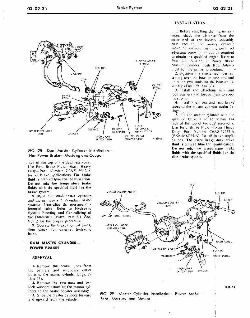
02-02-2 1 B r a k e S y s t e m 02-02-2 1
BUSHING 1
CLUTCH ASSIS1 SPRING
' \ SHAFT AUTOWTIC
-.--&,.,c" TRANSMISSION . -.. - . -,,,--,, 2140 SPACER
STOP LIGHT C L ~ T C H P E D A L SWITCH 13480 BUMPERSTOP H163e-A
FIG. 28-Dual M a s t e r Cyl inder Installation- N o n P o w e r Brake-Mustang a n d C o u g a r
INSTALLATION I
I. Before installing t h e ma.dtcr cyl- inder, check the distance f r t~ rn the outer end of the booster ;issc;nbly push rod to the n1;lster cylinder mounting surface. Turn the push rod adjustins screw in or out a s required to obtain the spccified length. Refer to Part 2-1. Section 2, Power Brakc: Master Cylinder Push Rod Adjust- ment for the proper procedure.
2. Position the master .cylinder as- sembly over the booster push rod and onto the two studs on the boostcr as- sembly (Figs. 29 thru 33).
3. Install the attaching nuts and lock washers and torque them to spec- ifications.
4. Install the front and rear brake' tubes to the rnnstcr cylinder outlet fit- tings.
5. ill the master cylinder with the specified b r ~ ~ k e fluid to : within I /4 inch of the top of the dual reservoirs. Use Ford Brake Fluid-Extra Heavy Duty---Part Number C6AZ-19542-A (ESA-M6C25-A) for a11 brake appli- cations. The extra heavy duty brake fluid is colored blue for identification. Do not mix low temperature brake fluids with the spccified fluids for the disc brake system.
.inch of the top of the dual reservoirs. Use Ford Brake Fluid-Extra Heavy Duty-Part Number C6AZ-19542-A ! for all brake applications. The brake fluid is colored blue for identification. Do not mix low temperature brake CLIP
fluids with the specified fluid for the brake system.
8. Bleed the dual-master cylinder and the primary and secondary brake
V A C U U M BOOSTER systems. Centralize the pressure dif- ferential valve. Refer to Hydraulic System. Bleeding and Centralizing of the Differential Valve, Part 2-1, Sec- tion 2 for the proper procedure.
9. Operate the brakes several times, then check for external hydraulic leaks.
DUAL MASTER CYLINDER- POWER BRAKES
R E M O V A L
1. Remove the brake tubes from the primary and secondary outlet SWITCH 13480 S P A C E R
ports of the master cylinder (Figs. 29 thru 33).
2. Remove the two nuts and two lock washers attachine the master cvl- H 1 6 4 2 . ~
inder to the brake b:oster assernbl;. 3. Slide the master cylinder forward FIG. 29--Master Cyl inder Installation-Power Brake-
and upward from the vehicle. Ford, Mercury a n d M e t e o r
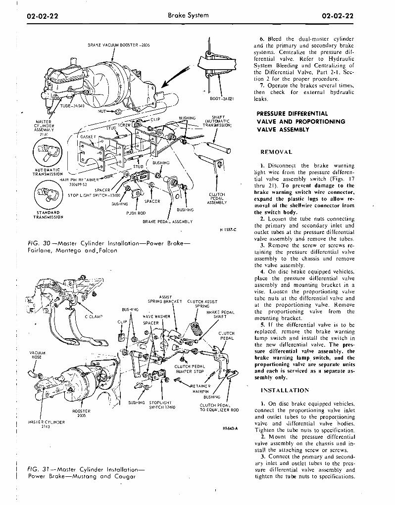
I 02-02-22 Brake System
B R A K E VACUUM BOOSTER -2005
BOOT-2A021
S T A N D A R D PUSH ROD TRANSMlSSlON
1 FIG. 30 -Master Cyl inder Installation-Power Brake- Fai r lane , M o n t e g o a n d ,Falcon
I 2005
I M A S T E R C Y L I N D E R I 2140
i
I FIG. 31 .--Master Cyl inder Installation- ) Power Brake-Mustang a n d C o u g a r
6. Bleed the dual-master cylinder and the primary and secondary brake systems. Cen~ral ize the pressure dif- ferential valve. Refer to Hydraulic System Bleeding and Centralizing of the Differential Valve, Part 2-1, Sec- tion 2 for the proper procedure.
7. Operate the brakes several times, then check for external hydraulic leaks.
PRESSURE DIFFERENTIAL
VALVE A N D PROPORTIONING
VALVE ASSEMBLY
R E M O V A L
1. Disconnect the brake warning light wire from the pressure differen- tial valve assembly switch (Figs. 17 thru 21). To prevent damage t o the brake warning switch wire connector, expand the plastic lugs to allow re- moval of the shellwire connector from the switch body.
2. Loosen the tube nuts connecting the primary and secondary inlet and outlet tubes at the pressure differential valve assembly and remove the tubes.
3. Remove the screw or screws re- taining the pressure differential valve assembly to the chassis and remove the valve assembly.
4. On disc brake equipped vehicles, place the pressure differential valve assembly and mounting bracket in a vise. Loosen the proportioning valve tube nuts a t the differential valve and a t the proportioning valve. Remove the proportioning valve from the mounting bracket.
5. I f the differential valve is to be replaced, remove the brake warning lamp switch and install the switch in the new differential valve. The pres- sure differential valve assembly. the brake warning lamp, switch, and the proportioning valve are separate units and each is serviced as a separate as- sembly only.
INSTALLATION
1. On disc brake equipped vehicles. connect the proportioning valve inlet and outlet tubes to the proportioning valve and differential valve bodies. Tighten the tube nuts to specification.
2. Mount the pressure differential valve assembly on the chassis and in- stall the attaching screw or screws.
3. Connect the primary and second- ary inlet and outlet tubes to the pres- sure differential valve assembly and tighten the tube nuts to specifications.
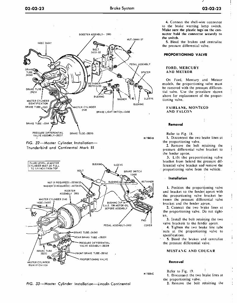
.I i 02 -02-23 Brake Sys tem 02-02-23
BOOSTER ASSEMBLY- 2005
NUT-34444 .S7
MASTER CYLINDER
BRAKE TUBE -2264
I \ PRESSURE DIFFERENTIAL BRAKE T U B E - ~ B ~ ~ ~ VALVE ASSEMBLY-20257
FIG. 32-Master Cylinder- Installation- Thunderbird a n d Continental Mark I l l
CYLINDER MUST aE FULL BUSHING\ SLEEVE
NUT (4 REQUIRED) -55 W A S H E R ' ~ ~ . R E Q U I R ~ D ) -44
PRESSURE DIFFERENTIAL VALVE ASSEMBLY-25328
PROPORTIONING VALVE
NG. 33-Master Cylinder Installation-Lincoln Continental
4. Connect the shell-wire connector to the brake warning lamp switch. Make sure the plastic lugslon the con- nector hold the connector securely to the switch.
5. Bleed the brakes and centralize the pressure differential valve.
PROPORTIONING VALVE
FORD, MERCURY AND METEOR
On Ford, Mercury and Meteor models, the proportioning valve must be removed with the pressure differen- tial valve. Use the procedure shown above for replacement of the propor- tioning valve.
FA1 RLANE, MONTEGO AND FALCON
Removal
Refer to Fig. 18. I. Disconnect the two brake lines at
the proportioning valve. 2. Remove the bolt retaining the
pressure differential valve' bracket to the fender apron.
3. L i f t t he proportioning valve bracket from behind the yessure dif- ferential valve bracket and4 rem'ove the proportioning' valve from the vehicle.
Installation
I. Position the proportioning valve and bracket to the fender1 apron with the proportioning valve bracket be- tween the pressure differential valve bracket and the fender apron.
2. Connect the two brake lines at the proportioning valve. Do not tight- en.
3. Install the bolt retainting the two valve brackets to the fender apron.
4. Tighten the two brake line tube nuts at the proportioning valve to specifications. I
5. Bleed the brakes and centralize the pressure differential valve.
I
MUSTANG AND COUGAR
Removal
I
Refer to Fig. 19. H 1530-C I. Disconnect the two brake lines at
the proportioning valve. ,
2. Remove the bolt retaining the
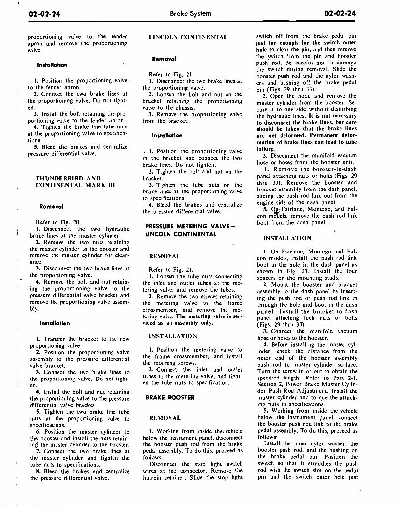
proportioning valve to the fender , apron and remove the proportioning
valve.
lnstallation
I. Position the proportioning valve to the fender apron.
2. Connect the two brake li.nes a t the proportioning valve. Do not tight- en.
3. Install the bolt retaining the pro- portioning valve to the fender apron.
4. Tighten the brake line tube nuts at the proportioning valve to specifica- tions.
5. Bleed the brakes and centralize pressure differential valve.
T H U N D E R B I R D A N D C O N T I N E N T A L M A R K I l l
Removal
Refer to Fig. 20. I 1. Disconnect the two hydraulic ' brake lines a t the master cylinder.
2. Remove the two nuts retaining the master cylinder to the booster and remove the master cylinder for clear- ance.
3. Disconnect the two brake lines at the proportioning valve.
4. Remove the bolt and nut retain- ing the proportioning valve to the pressure differential valve bracket and remove the proportioning valve assem- bly.
Installation
1. Transfer the bracket to the new proportioning valve.
2. Position the proportioning valve assembly to the pressure differential valve bracket.
3. Connect the two brake lines to the proportioning valve. Do not tight- en.
4. Install the bolt and nut retaining the proportioning valve to the pressure differential valve bracket.
5. Tighten the two brake line tube nuts at ' the proportioning valve to specifications.
6.' Position the master cylinder to the booster and install the nuts retain- ing the master cylinder to the booster.
7. Connect the two brake lines at the master cylinder and tighten the tube nuts to specifications.
8. , Bleed the brakes and centralize the pressure differential valve.
Brake System
L I N C O L N C O N T I N E N T A L
Removal
Refer to Fig. 21. 1. Disconnect the two brake lines at
the proportioning valve. 2. Loosen the bolt and nut on the
bracket retaining the proportioning valve to the chassis.
3. .Remove the proportioning valve from the bracket.
@ 1. Position the proportioning valve in the bracket and connect the two brake lines. Do not tighten.
2. Tighten the bolt and nut on the bracket.
3. Tighten the tube nuts on the brake lines at the proportioning valve to specifications.
4. Bleed the brakes and centralize the pressure differential valve.
PRESSURE METERING VALVE- l l N C O L N CONTINENTAL
R E M O V A L
Refer to Fig. 21. 1. Loosen the tube nuts connecting
the inlet and outlet tubes a t the me- tering valve, and remove the tubes.
2. Remove the two screws retaining the metering valve to the frame crossmember, and remove the me- tering valve. The metering valve is ser- viced as an assembly only.
1. Position the metering valve to the frame crossmember, and install the retaining screws.
2. Connect the inlet and outlet tubes to the metering valve, and tight- en the tube nuts to specification.
BRAKE BOOSTER
1. Working from inside the, vehicle below the instrument panel, disconnect the booster push rod from the brake pedal assembly. T o do this, proceed as follows:
Disconnect the stop light switch wires a t the connector. Remove the hairpin retainer. Slide the stop light
switch off from the brake pedal pin just far enough for the switch outer 'hole to clear the pin, and then remove the switch from the pin .and booster push rod. Be careful not to damage the switch during removal. Slide the booster push 'rod and the nylon wash- ers and bushing off the brake pedal pin (Figs. 29 thru 33).
2. Open the hood and remove the master cylinder from the booster. Se- cure, it to one side without disturbing the hydraulic lines. I t is not necessary to disconnect the brake lines, but care should be taken that the brake lines are not deformed. Permanent defor- mation of brake lines can lead to tube failure.
3. Disconnect the manifold vacuum hose or hoses from the booster unit.
I. R e m o v e the booster-to-dash panel attaching nuts or bolts (Figs. 29 thru 33). Remove the booster and bracket assembly from the dash panel, sliding the push rod link out from the engine side of the dash panel.
5. O n , Fairlane, Montego, and Fal- w con models, remove the push rod link boot from the dash panel.
I N S T A L L A T I O N
I. On Fairlane, Montego and Fal- con models, install the push rod link boot in the hole in the dash panel as shown in Fig. 23. lnstall the four spacers on the mounting studs.
2. Mount the booster and bracket assembly to the dash panel by insert- ing the push rod or push.rod link in through the hole and boot in the dash p a n e l . Ins ta l l the bracket- to-dash panel attaching lock nuts or bolts (Figs. 29 thru 33).
3. Connect the manifold vacuum hose or hoses to the booster.
4. Before installing the master cyl- inder, check the distance from the outer end of the booster assembly push. rod to master cylinder surface. Turn the screw in or out to obtain the specified length. Refer to Part 2-1, Section 2, Power Brake Master Cylin- der Push Rod Adjustment. Install the master cylinder and torque the attach- ing nuts to specifications.
5. Working from inside the vehicle below the instrument panel, connect the booster push rod link to the brake pedal assembly. To d o this, proceed as follows:
Install the inner nylon washer, the booster push rod, and the bushing on the brake pedal pin. Position the switch so that it straddles the push rod with the switch slot on the pedal pin and the switch outer hole just
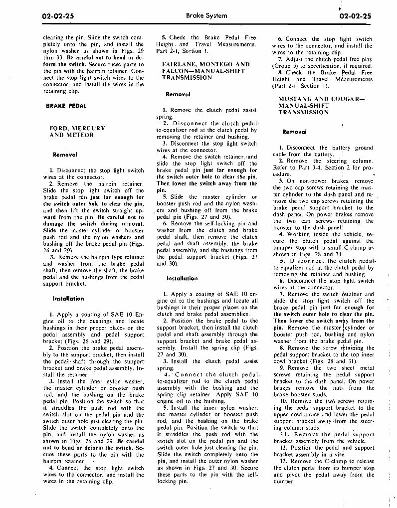
Brake System
clearing the pin. Slide the switch com- pletely onto the pin, and install the nylon washer as shown in Figs. 29 thru 33. Be careful not to bend or de- form the switch. Secure these parts to the pin with the hairpin retainer. Con- nect the stop light switch wires to the connector, and install the wires in the retaining clip.
BRAKE PEDAL
F O R D , M E R C U R Y A N D MET'EOR
Removal
1. Disconnect the stop light switch wires at the connector.
2. Remove the hairpin retainer. Slide the stop light switch off the brake pedal pin just far enough for the switch outer hole to clear the pin, and then lift the switch straight up- ward from the pin. Be careful not to damage the switch during removal. Slide the master cylinder or booster push rod and the nylon washers and bushing off the brake pedal pin (Figs. 26 and 29).
3. Remove the hairpin type retainer and washer from the brake pedal shaft, then remove the shaft, the brake pedal and the bushings frnm the pedal support bracket.
Installation
1. Apply a coating of SAE 10 En- gine oil to the bushings and locate bushings in their proper places on the pedal assembly and pedal support bracket (Figs. 26 and 29).
2. Position. the brake pedal assem- bly to the support bracket, then install the pedal.shaft through the support' bracket and brake pedal assembly. In- stall the retainer.
3. Install the inner nylon washer, the master cylinder or booster push rod, and the bushing on the brake pedal pin. Position the switch so that it straddles the push rod with the switch slot on the pedal pin and the switch outer hole just clearing the pin. Slide the switch completely onto the pin, and install the nylon washer as shown in Figs. 26 and 29. Be careful not to bend or deform the switch. Se- cure these parts to the pin with the hairpin retainer.
4. Connect the stop light switch wires to the connector, and install the wires in the retaining clip.
5. Check the Brake Pedal Free Height. and Travel Measurements, Part 2-1, Section 1.
F A I R L A N E , M O N T E G O A N D F A L C O N - M A N U A L - S H I F T T R A N S M I S S I O N
Removal
1. Remove the clutch pedal assist spring.
2. D i s c o n n e c t the clutch pedal- to-equalizer rod at the clutch pedal by removing the retainer and bushing.
3. Disconnect the stop light switch wires at the connector.
4. Remove the switch retainer,,and slide the stop light switch off the brake pedal pin just far enough for the switch outer hole to clear the pin. Then lower the switch away from the pin.
5. Slide the master cylinder or booster push rod and the nylon wash-
, ers and bushing off from the brake pedal pin (Figs. 27 and 30).
6. Remove the self-locking pin and washer from the clutch and brake pedal shaft, then remove the clutch pedal and shaft assembly, the brake pedal assembly, and t h ~ bushings from the pedal support bracket (Figs. 27 and 30).
Installation
1. Apply a coating of SAE 10 en- gine oil to the bushings and locate all bushings in their proper places on the clutch and brake pedal assemblies.
2. Position the brake pedal to the support bracket, then install the clutch pedal and shaft assembly through the support bracket and brake pedal as- sembly. Install the spring clip (Figs. 27 and 30).
3. Install the clutch pedal assist spring.
4. C o n n e c t t h e c l u t c h p e d a l - to-equalizer rod to the clutch pedal assembly with the bushing and the spring clip retainer. Apply SAE 10 engine oil to the bushing.
5. Install the inner nylon washer, the master cylinder or booster push rod, and the bushing on the brake pedal pin. Position the switch so that it straddles the push rod with the switch slot on the pedal pin and the switch outer hole just clearing the pin. Slide the switch completely onto the pin, and install the outer nylon washer as shown in Figs. 27 and 30. Secure these parts to the pin with the self- locking pin.
6. Connect the stop light switch wires to the connector, and install the wires to the retaining clip:
7. Adjust the clutch pedal free play (Group 5) to specification, i f required.
8. Check the Brake Pedal Free Height and Travel ~ e a s u r e m e n t s (Part 2-1, Section I).
M U S T A N G A N D C O U G A R - M A N U A L - S H I F T T R A N S M I S S I O N
Removal
1. Disconnect the battery ground cable from the battery.
2. Remove the steering column. Refer to Part 3-4, Section 2 for pro- cedure. I
3. On non-power brakes, remove the two cap screws retaining the mas- ter cylinder to the dash panel and re- move the two cap screws retaining the brake pedal support bracket to the dash panel. On power brakes remove the two cap screws- retaining the, booster to the dash panel!
4. Working inside the vehicle, se- cure the clutch pedal against the bumper stop with a small IC-clamp as shown in Figs. 28 and 3 1.
5. D i s c o n n e c t the clutch pedal- to-equalizer rod at the clutch pedal by removing the retainer and, bushing. I
6. Disconnect the stop light switch wires at the connector.
7. Remove the switch fetainer and slide the stop light switch off the '! brake pedal pin just far enough for ,
the switch outer hole to clear the pin. Then lower the switch away from the pin. Remove the master !cylinder or ! booster push rod, bushing and nylon washer from the brake pedal pin.
8. Remove the screw retaining the pedal support bracket to the top inner cowl bracket (Figs. 28 and 31).
9. Remove the two sheet metal screws retaln~ng the pedal support bracket to the dash panel. On power brakes remove the nuts from the brake booster studs.
10. Remove the two screws retaln- , ing the pedal support brqcket to the , upper cowl brace and lower the pedal support bracket away from the steer- ing column studs. I
11. R e m o v e t h e pedal support bracket assembly from the vehicle.
12. Position the pedal and support , bracket assembly in a vise.
13. Remove the C-clamp to release the clutch pedal from its bumper stop and p~vot the pedal away from the bumper.
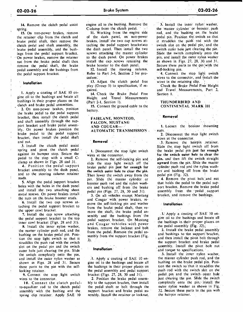
. .
Brake System . : . 02-02-26
14. ~ e h o v e the clutch pedal assist spring.
15. On non-power brakes, remove the retainer clip from ,the clutch and brake pedal shaft, then remove the clutch pedal 'and shaft assembly, the brake pedal assembly, and the bush- ings from the pedal support bracket. On power bra.kes, remove the retainer nut -from the brake pedal shaft .then remove the pedal shaft, the brake pedal assembly and the bushings from the pedal support bracket.
Installation
1. Apply a coating of SAE 10 en- gine oil to the bushings and locate all bushings in their proper places on the clutch and brake pedal assemblies.
2. On non-power brakes, position the brake pedal to the pedal support bracket, then install the clutch pedal and shaft assembly through the sup- port bracket and brake pedal assem- bly. On power brakes position the brake pedal to the pedal support bracket, then install the pedal shaft and nut.
3. lnstall the clutch pedal assist spring and pivot the clutch pedal against its bumper stop. Secure the pedal to the stop with a small C- clamp as shown in Figs. 28 and 31.
4. P o s i t i o n t h e p e d a l s u p p o r t bracket assembly to the dash panel, and to the steering column retainer studs.
5. Align the pedal support bracket holes with the holes in the dash panel and install the two attaching sheet metal screws. On power brakes install the nuts on the brake booster studs.
6. Install the two cap screws at- taching the pedal support bracket to the upper cowl bracket.
7. lnstall the cap screw attaching the pedal support bracket to the top inner cowl bracket (Figs. 28 and 31).
8. Install the inner nylon washer, the master cylinder push rod, and the bushing on the brake pedal pin. Posi- tlon the stop light switch so that it straddles the push rod with the switch slot on the pedal pin and the switch outer hole just clearing the pin. Slide the switch completely onto the pin, and install the outer nylon washer as shown in Figs. 28 and 31. Secure these parts to the pin with the self- locking retainer.
9. Connect the stop light switch wires to the connector.
10. C o n n e c t t h e c l u t c h p e d a l - to-equalizer rod to the clutch pedal assembly with the bushing and the spring clip retainer. Apply SAE 10
engine oil to the bushing. Remove the C-clamp from the clutch pedal.
11. Working from the engine side of the dash panel, on non-power brakes, install the two cap screws at- taching the pedal support bracketato the dash panel. Then install the two screws attaching the master cylinder to the dash panel. On power brakes install the cap screws retaining the brake booster to the dash panel.
12. lnstall the steering column. Refer to Part 3-4, Section 2 for pro- cedure.
13. Adjust the clutch pedal free play (Group 5) to specification, if re- quired.
14. Check the Brake Pedal Free Height and Travel Measurements (Part 2-1, Section I).
15. Connect the ground cable to the battery.
FA1 RLANE, MONTEGO, FALCON, MUSTANG AND COUGAR- . AUTOMATlC TRANSMISSION .
Removal
I. Disconnect the stop light sw~tch wires at the connector.
2. Remove the self-locking pin and slide the stop light switch off the brake pedal pin just far enough for the switch outer hole to clear the pin. Then lower the switch away from the pin. Slide the master cylinder or booster push rod and the nylon wash- ers and bushing off from the brake pedal pin (Figs. 27, 28, 30 and 31).
3. On all vehicles except Mustang and Cougar with power brakes, re- move the self-locking pin and washer from the brake pedal shaft, then re- move the shaft, the brake pedal as- sembly and the bushings from the pedal support bracket. On Mustang a n d C o u g a r veh ic les with power brakes, remove the locknut and bolt from the pedal. Remove the pedal as- sembly from the support bracket (Fig. 3).
Installation
1. Apply a coating of S A E 10 en- gine oil to the bushings and locate all the bushings in their proper places on the pedal assembly and pedal support bracket (Figs. 27, 28, 30 and 3 1).
2. Position the brake pedal assem- bly to the support bracket, then install the pedal ,shaft or bolt through the support bracket and brake pedal as- sembly. Install the retainer or locknut.
3. lnstall the inner nylon washer, the master cylinder or booster. push rod, and the bushing on the brake pedal pin. Position the switch so that it straddles the push rod with the switch slot on the pedal pin,' and the switch out'er hole just clearing the pin. Slide the switch completely onto the pin, and install the outer nylon washer as shown in Figs. 27, 28, 30 and 31. Secure these parts .to the pin :with the self-locking pin.
4. Connect the stop light switch wires to the connector, and install the wires in the retaining clip.
Check the Brake Pedal ~ r e k Height and Travel Measurements, Part 2, Section I .
THUNDERBIRD AND CONTINENTAL MARK 111
. . Removal . .
1. Loosen the booster mounting nuts.
2. Disconnect the stop light switch wires at the connector.
3. Remove the hairpin ,retainer. Slide the stop light switch off from the brake pedal pin just far enough for the switch outer hole to clear the pin, and then l ~ f t the switch straight upward from the pin. Slide the master cylinder push rod and the nylon wash- ers and bushing off from the brake pedal pln (Fig. 32).
4. Remove the pivot bolt and nut that holds the pedal to the pedal sup- port bracket. Remove the brake pedal assembly from the pedal support bracket, ,and remove the bushings.
Installation
1. Apply a coating of SAE 10 en- gine oil to the bushings and locate all the bushings in their proper places on the pedal assembly (Fig. 32).
2. lnstall the brake pedal assembly and bushings to the support bracket, and then install the pivot bolt through the support bracket and brake pedal assembly. lnstall the pivot bolt nut and torque to specifications.
3. Install the inner nylon washer, the master cylinder push rod: and the bush~ng on the brake pedal pin. Posi- tlon the switch so that it straddles the push rod with the switch slot on the pedal pin and the switch- outer hole just clearing the pin. Slide the switch completely onto the pin, install the outer nylon washer as shown in Fig. 32. Secure these parts to the pin with the hairpin retainer. , , '
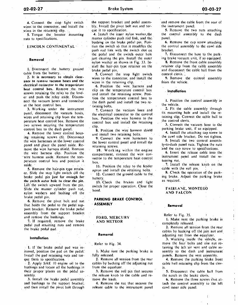
4. Connect the stop light switch wires to the connector, and install the wires in the retaining clip.
5. Torque the booster mounting nuts to specifications.
Ll NCOLN CONTl NENTAL
I . ' D i s c o n ~ c t the . battery cable from the battery.
2; It is necessary to obtain' clear- ance to remove vacuum hoses and'the electrical connector to the temperature heat control box. Remove , the . two screws retaining the relay to the fend- er and push the'.relay aside. Discon- nect the vacuum hoses and ,connector at the heat control box.
3. Working under the instrument panel, disconnect the vacuuin hoses, wires and retaining clip from the tem- perature heat control box. Remove the two screws securing the temperature control box to the dash pan$
4. Remove the lower control hous- ing retaining screws (6). Disconnect the wire harnesses at the lower control panel and place .the panel aside. Re- move the wire harness shield. Remove the wire harness clip. Position the wire harness aside. Remove the tem- perature control box and position it aside. . , .
5. Remove the hair-pin type reiain- er. Slide the stop light switch off the brake pedal pin just far enough for, the switch outer hole to clear. the pin. Lift- the switch upward from the pin. Slide the master cylinder push rod, nylon washers and bushing off the brake pedal pin.
6. Remove the pivot bolt and nut that holds the pedal to the pedal sup- port bracket. Remove the brake pedal assembly from the support bracket and remove the bushings.
7. If required, remove the brake pedal pad retaining nuts and remove the brake pedal pad.
Installation
1. I f the brake pedal pad was re- moved, position the pad on the pedal. Install the pad retaining nuts and tor- que them to specification.
2. Apply SAE 10 engine oil to the bushings and locate all the bushings in the~r proper places on the pedal as- sembly.
3. Install the brake pedal assembly and bushings to the support bracket, and then install the pivot bolt through
Brake System
the support bracket and pedal assem- bly. Install the pivot bolt nut and tor- que it to specification.
4. Install the inner nylon washer-the master cylinder push rod link, and the bushing on the brake pedal pin. Posi- tion the switch so that it straddles the push rod link with the switch slot on the pedal and the switch outer hole just clearing the pin. install the outer nylon washer as shown in Fig. 33. In- stall the hair-pin type retainer on the brake pedal pin.
5. Connect the stop light switch wires to the connector, and install the wires in the retaining clip.
6. Position the wire^ harness and clip on the temperature control box and install the retaining screw. Posi- tion the temperature control box to the dash panel and install the two re- taining bolts.
7. Connect the vacuum lines and the electrical connector to the control box. Position the wire harness to the control box and install the retaining clip.
8. Position the wire harness shield and install two retaining bolts.
9. Connect the wire harnesses to the lower control panel and install the retaining screws.
10. W o r k i n g within the engine compartment, connect the wire con- nector to the temperature heat control box.
11. Position the relay to the fender apron and install the retaining bolts.
12. Connect the ground cable to the battery.
13. Check the brakes and light switch for proper operation. Close the hood.
PARKING BRAKE CONTROL ASSEMBLY
FORD, MERCURY' . ,
AND METEOR , .
, Removal
Refer to Fig. 34.
1. Make sure the parking brake is fully released.
2. Remove all tension from the rear cables by backing off the adjusting nut from the equalizer.
3. Remove the roll pin that secures the release knob to the cable and re- move the knob.
4. Remove the nut that secures the release cable to the instrument panel
and remove the cable from the rear of the instrument panel. I
5. Remove the two nuts attaching the control assembly to the dash panel.
6. Remove the cap screw attaching the control assembly to the cowl side bracket.
7. Disconnect the hose do the park- ing brake vacuum unit, i f so equipped.
8 Remove the front cable assembly retamer clip from the cable assembly and disconnect the cable ball from the control clevis. .
9. Remove the control assembly from the vehicle.
Installation
I. Position the control assembly in the vehicle.
2. Fit the cable assembly through its mounting hole and install the re- taining clip,. Connect the cable ball to ,the control clevis.
3. ,Connect the vacuum hose to the parking brake unit, i f so equipped.
4. Install the attaching cap screw to the cowl side bracket. Do not tighten.
5. Install the two control assemb- ly-to-dash panel nuts. Tighten the nuts and the cap screw to specifications.
6. Insert the release cable into the instrument panel and install the re- taining nut.
7. Install the release knob on the cable with the roll pin.
'
8. Check the operation of the park- ing brake. Adjust the parking brake as required.
F A I R L A N E , MONTECO AND FALCON
I
Removal
Refer to Fig. 35. I , 1. Make sure the parking brake is
completely released. 2. Remove all tension from the rear
cables by backing off the jam nut and 1
adjusting nut from the equalizer. 3. Working inside the vehicle, re-
move the four' bolts and one nut re- taining the, left a ir vent and cable as- sembly to the dash and instrument panels. Remove the vent assembly.
4. Remove the parking brake front cable ball retaining clip from the clev- is. ' 5. Disconnect the' cable 'ball from the notch in the brake clevis.
6. Remove the three screws that at- tach the control assembly to 'the left cowl inner side panel.
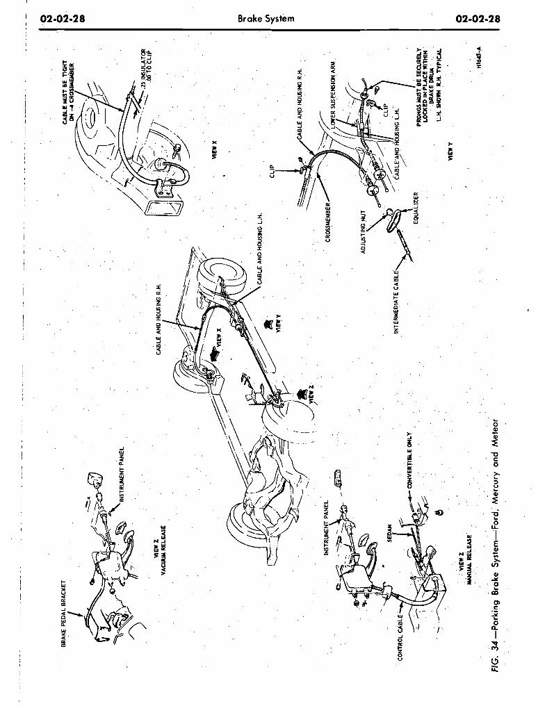
--
--
-
-
-
- - -
-
- - - --
- -
- . -
- -
- -
- -
--
-
- -
--
-
--
--
- - - - - - - -
-
-
BR
AK
E P
ED
AL
BR
AC
KE
T C
AB
LE W
ST
BE
n~
n~
/ ON
-4
CR
OS
SY
EIIB
ER
INS
TRU
ME
NT
PA
NE
L
VIEW
z
VAC
UU
M R
ELE
PJE
VIEW
X
4
CA
BLE
AN
D H
WS
ING
L.H
.
CR
OSS
MEM
BER
SU
SPEN
SIO
N A
RM
CO
NTR
OL
INTE
RM
ED
IATE
CA
BLE
CQ
NV
ER
TleL
E O
NLY
PRO
NG
S M
UST
BE
SE
CU
RE
LY
LOC
I(ED
IN
PLA
CE
WIT
HIN
B
RA
KE
DR
UM
L
K W
OW
R.K
T
YP
ICA
L
nE
w Y
VIEW
z
YAHUM
RE
LEA
SE
HIM
-A
FIG
. 34
-Par
kin
g
Bra
ke S
yste
m-F
ord
, M
ercu
ry a
nd
Me
teo
r
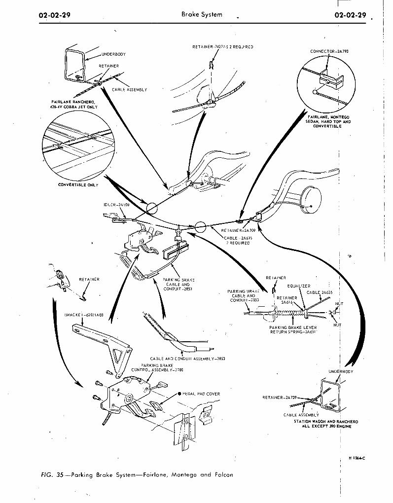
Brake System -
FIG. 35--Parking Brake System-Fairlane, Montego and Falcon
7. Disconnect the wire lead at the parking brake warning light switch and remove the control assembly.
Installation
I. Connect the wire lead to the parking brake warning light switch.
2. Position the control assembly to the cowl inner side panel and install the three attaching screws.
3. Connect the ball-end of the park- ing brake front cable assembly lo the control assembly, and install the hair- pin retainer.
4. Position the cable ball in the notch in the brake clevis.
5. Position the left air vent assem- bly to the dash and instrument panels. Install the four bolts and one nut re- taining the air vent to the panels.
6. Check the operation of the park- ing brake. Adjust the parking brake.
MUSTANG AND COUGAR
Removal
Refer to Fig. 36.
1. Make sure the parking brake is completely released.
2. Remove all tension from the rear cables by backing off the jam nut and adjusting nut from the equalizer.
3. Disconnect the wire lead at the parking brake warning light switch (if so equipped).
4. Remove the parking brake front cable ball retaining clip from the clev- i s .
5. Remove the parking brake warn- ing light switch and attaching screw (if so equipped).
6. Disconnect the cable ball from the notch in the brake clevis.
7. Remove the three screws that at- tach the control assembly to the left cowl inner side panel.
8. Pull the control away from the cowl panel. Remove the hair-pin re- tainer securing the front cable assem- bly to the control assembly. Remove the control assembly.
Installation
I I. Connect the ball-end of the park-
ing brake front cable assembly to the , control assembly, and install the hair- I pin retainer. I 2. Position the control assembly to
the cowl inner side panel and install I the three attaching screws.
I
Brake System
3. Position the parking brake warn- ing light switch and install the attach- ing screw. Connect the parking brake warning light switch wire lead (if vehi- cle is so equipped). ,
4. Position the cable ball in the notch in the brake clevis.
5. Check the operation of the park- ing brake. Adjust the parking brake.
THUNDERBIRD AND CONTINENTAL MARK I11
Removal
Refer to Fig. 37.
1. Remove the two nuts retaining the control to the dash panel.
2. Remove two screws from the left scuff da te .
3. kemove one screw retaining the left cowl trim panel and remove the panel.
4. Remove the two screws retaining the left air duct and remove the air duct.
5. Remove the two screws retaining the dimmer switch and position the switch out of the way.
6. Remove the clip retaining the cable assembly to the control.
7. Disconnect the cable ball from the control clevis.
8. Disconnect the vacuum hose at the brake release.
9. Remove the bolt retaining the cpntrol to the cowl side bracket and remove the control.
Installation
1. Position the parking brake con- trol in the vehicle.
2. Install the cable assembly in the control and connect the cable ball to the control clevis.
3. lnstall the clip retaining the cable to the control.'
4. Install the bolt retaining the con- trol to the cowl side bracket.
5. Connect the vacuum hose to the parking brake release vacuum motor.
6. Position the dimmer switch and install the retaining screws.
7. Position the air duct and install the retaining screws.
8. Position the cowl trim panel and install the retaining screw.
9. Install the two scuff plate screws. 10.' Install the two nuts retaining
the control to the dash panel. 11. Adjust the parking brake.
Refer to Fig. 38.
I. Raise the vehicle on a hoist. 2. Loosen the parking brake cable
a d j u s t i n g n u t , remove the return spring and remove the cable ball end from the equalizer.
3. Lower the vehicle. 4. Disconnect the battery. 5. Disconnect the wire harness con-
nector and two vacuum hoses at the Automatic Temperature Control box.
6. Working inside the vehicle, re- move the windshield wiper control knob and ,bezel from the lower control panel.
7. Remove the screws retaining the lower control panel. Lower the control panel and disconnect wire harnesses and vacuum hoses. Position the con- trol panel aside.
8. Remove the screw retaining the plastic wire cover and place the cover aside. 4i
9. Disconnect three vacuum hoses and the wiring harness a t the Auto- matic Temperature Control box. 10. Remove the two screws retain-
ing the Automatic Temperature Con- trol box to the dash panel and remove the box for clearance.
11. Disconnect the ball end of the cable from the control clevis.
12. Remove the four bolts retaining the control to the dash panel and lower instrument panel flange.
13. Disconnect the vacuum release hose from the control and remove the control assembly from the vehicle..
Installation
1. Position the control assembly to the dash panel and instrument panel flange and install the four retaining screws.
2. Connect the vacuum release hose to the control assembly.
3. Connect the cable ball to the control clevis.
4. Position the Automatic Temper- ature Control box to the dash panel and install the retaining screws.
5. Connect the wiring harness and vacuum hoses to the Automatic Tem- perature Control box.
6. Position the plastic wire cove1 and install the retaining screw.
7. Connect the wire harnesses and vacuum lines to the lower control panel and position the panel to the in-
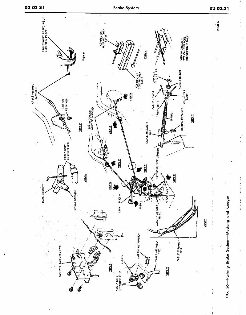
FIG
. 36
-Par
kin
g
Bra
ke S
yste
m-M
usta
ng
an
d C
ou
ga
r
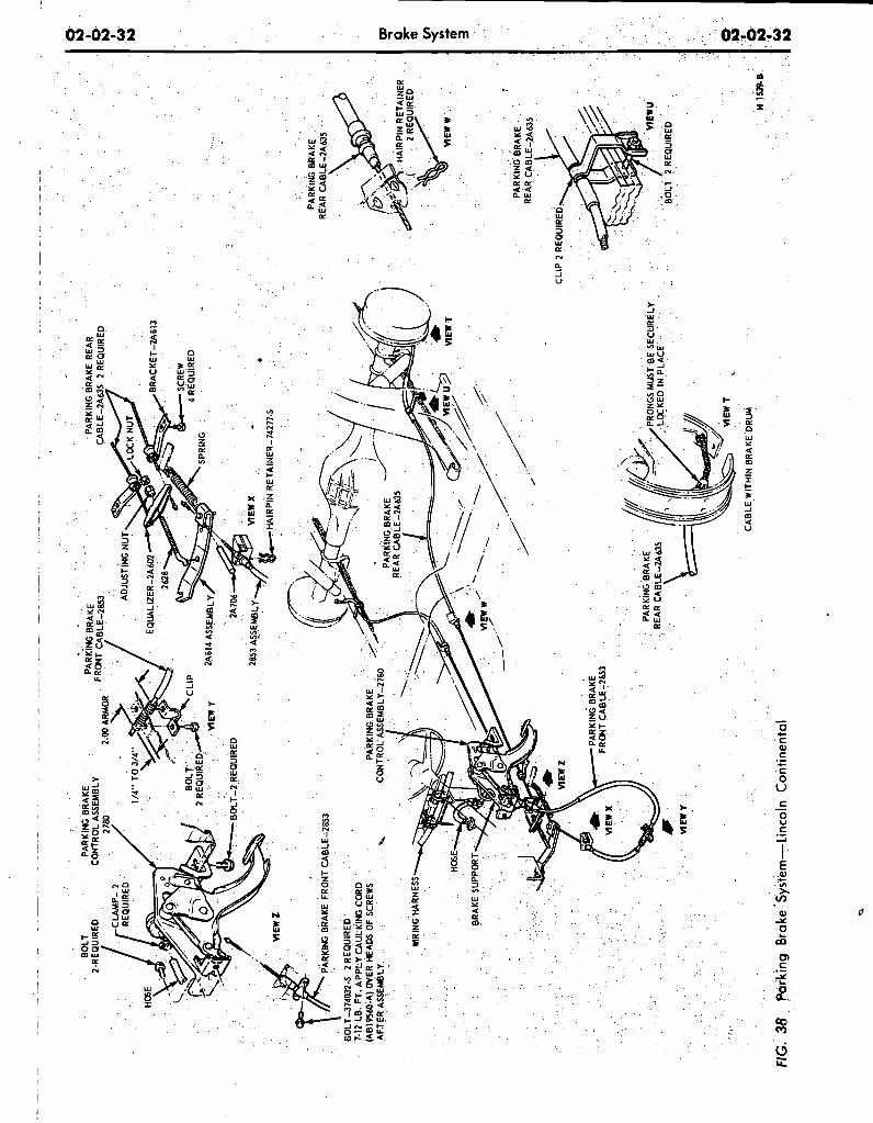
PA
RK
ING
BR
AK
E
RE
AR
CA
BLE
-2A
63S
PA
RK
ING
BR
AK
E
REA
R C
AB
/€-Z
A63
5
-IP
2 R
EQ
UIR
ED
FIG
. 38
P
arki
ng
6ra
ke
'~~
st'
ern
-~in
co
ln C
on
tin
enta
l
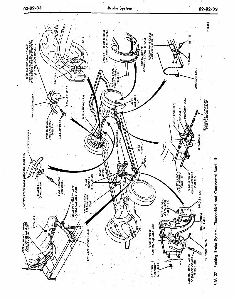
FIG
..37-
Par
king
B
rake
syi
tem
-~hu
nder
bird
an
d 'C
ontin
enta
l Mar
k Ill
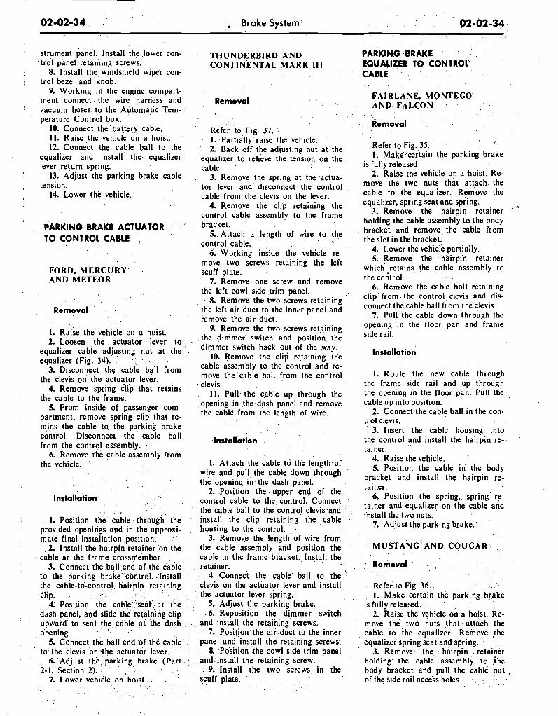
02-02-34 L
, Brake System
strument panel. Install. the ,lower con- trol panel retaining screws.
8. Install the windshield wipe'r con- trol bezel and' knob.
9. Working in the engine compart- ment connect the' wire harness and vacuum, hoses. to the.Atitomatic Tem- .' perature Control box.
10. Connect ttie ' battery cable. 11. Raise the vehicle on a hoist. ,.
12. Connect the cable ball to the equalizer and install' the. equalizer lever return spring. :
13. Adjust the parking brake cable tension.
14. Lower the vehicle.
'PARKING BRAKE ACTUATOR- TO CONTROL CABLE :
FORD, MERCURY AND METEOR
. . . . . .
Removal. ' . ' .
. . .
1. Raise the vehicle. on a hoist. 2. Loosen , the . actuator, .:lever to
equalizer cable adjusting nut at the .. . equalizer (Fig. 34). ,:: '
. ' . - . 3.' Disconnect the cable. bail from.
the clevis on the actuator lever. 4. Remove spring clip: that retains
the cable to the frame. 5. From inside of passenger com-
partment, remove spring clip that re-
THUNDERBIRD A,ND CONTINENTAL MARK '111
Removal
Refer to Fig. 37. 1. Partially raise the vehicle. 2. Back off the adjusting nut at the
equalizer to relieve the tension on the cable.
3. Remove the spring at the actua- tor lever and disconnect the control cable from the clevis o n the, lever. .
4. Remove the clip retaining. the control cable assembly to. the frame bracket.
5.. Attach a length of wire to the . . .
control cable. :
6. Working inside ,the vehicle re- move two screws retaining the left scuff plate. . ' . .
7. Remove one screw a n d remove the left cowl side .trim panel.
8. Remove the .two screws retaining the left air duct to the inner panel and remove the air duct.
9. Remove the two screws retaining the dimmer switch and position the dimmer switch back out of the way.
10. Remove the clip retaining the cable assembly to the control and re- move the cable ball from the control clevis.
11. Pull the cable up through the opening in the dash panel and remove the cable from the length of wire.
&ins 'the cable .to the parkink brake . . . ,
control. Disconneot thk cable ball from the control assembly. - Installation
. . 6. Remove the cabie assembly from
the vehicle. " 1. Attach t h e cable t o the lengthof- . . 'wire and pull the cable down through
the opening in.the dash panel. , .., . ' . . .
, . .. 2. Position t he , upper end of the lnstaliation
. . . . . . control cable to the, control.. Connect
. , . r . the cable ball to the contro!clevis.and " . .
1. Po~itibn 'the' cable . through'' the install the clip retaining the cab le . ; , .
-0penirigS and in the approxi- , , housing to the control. . .:
mate final installation,,position.. , ; . 3. Remove the length of wire from ,. 2. Install the hairpin retainer'bn the the cable ' assembly arid position the
cable at the frame crossmember. ,., . . cable in the frame bracket., Install the -3. Connect the ball. en&of the cable . retainer. . .
fo the' barking brake' control. .:Install , ' 4. Connect. the cable. ball to .the ':'
the cable-to-control.,, haifpin retaining . clevis on the actuator lever and install . . .clip. . . ' , ... ,. , . . , . . ' . . .. , : - the actuator lever spring. . .
4. ~os i t id r i ih& cable''.'&&,, a t , the . : 5. Adjust the parking brake. , .
dash panel, and slide theretaining clip. .6; , Reposition the dimmer switch '
upward' 'to seal the, sable' a t the dash , , and install the 'retaining screws. , . . . .
o'pening. , . . . 7. Positionthe air.duct to the inner 5. Connect the ball end b.f thl cable : panel and install the retaining screws.
tq'the clevis'on'the actuatdi lever.: - . 8 Position. thecowl side trim panel 6. .Adjust the, .parking ,brake (Par t . : . .and: install, the retaining screw.
. . . , . 2-1, Section 2). . : , .
.. . . . . .': . . : 9. Install the two screws, in the 7.' Lower vehiile on:$ois.t., . . , scuff plate. .. . .
, , . . . . . .
PARKING BRAKE EQUALIZER TO CONTROL' CABLE
FAIRLANE, MONTEGO . AND FALCON : . '
. - ~ :
.- Removal , . . '
. .
. . . ,
Refer t o Fig. 35. i
1. Make'certain the parking brake is fully released.
2. Raise the vehicle on a .hoist. Re- move t h e two nuts that attach, the cable to the equalizer. Remove the equalizer, spring seat and spring.
3. Remove the hairpin retainer ' a
holding the cable assembly to the body . bracket and remo.ve the cable from
the slot in the bracket. 4. Lower the vehicle partially. 5. Remove the hairpin retainer
which oretains the cable assembly to the control.
6. Remove the cable bolt retaining clip from the control clevis and dis- connect the cable ball from the clevis.
7. Pull the cable down through the opening in the floor pan and frame side rail.
Installation
1. Route the new cable through the frame side rail and up through the opening in the floor pan. Pull the cable up into position.
2. Connect the'cable ball in the con- trol clevis.
3. Insert the cable housing into the control and install the hairpin re- tainer.
4. Raise the vehicle. 5. Position the cable in the body
bracket and install the hairpin re- tainer.
6. Position the spring,. spring' re- tainer and equalizer on the cab.le and i'nstall the two nuts.
7. .Adjust the parking brake.'
Removal . ., . . . .
Referto Fig. 36. , . 1. ,Make certain the parking brake
. , . isfully released. . .
2. Raise the vehicle on a hoist. Re- move the. two nuts- that attach. the cable to the equalizer. Remove ttie equalizer spring seat and spring., . , . ,
3. Remove the, : hairpin . retainer holding' the cable assembly t o , ihe body bracket and pull the cable o u t . . of the side rail a ca s s holes. : , ,, ., . .
: . . .
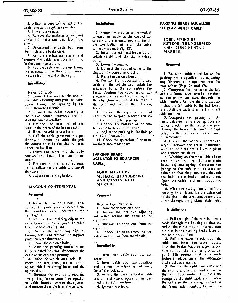
Brake System
4. Attach a wire to the end of the cable to assist in routing new cable.
5. Lower the vehicle. 6. Remove the parking brake front
cable ball retaining clip from the clevis.
7. Disconnect the cable ball from the notch in the brake clevis.
8: Remove the hairpin retainer and ' remove the cable assembly from the
brake control assembly. 9. Pull the cable assembly up through
the opening in the floor and remove the wire from the end of the cable.
Installation
Refer to Fig. 36. 1. Connect the wire to the end of
the cable assembly and pull the cable down through the opening in the floor. Remove the wire.
2. Connect the cable assembly to the brake control assembly and in- stall the hairpin retainer.
3. Position the ball end of the cable in the notch of the brake clevis.
4. Raise the vehicle on a hoist. 5. Pull the cable grommet into po-
sitionsand route the cable through the access holes in the side rail and under the fuel line.
6. Insert the cable into the body bracket and install the hairpin re- tainer.
7. Position the spring, spring seat, and equalizer on the cable and install the two nuts.
8. Adjust the parking brake.
LINCOLN CONTINENTAL
Removal II
1. Raise the car on a hoist. dis- connect the parking brake cable from the equalizer lever underneath the car (Fig. 38).
2. Remove the retaining clip at the cable bracket, and disengage the cable from the bracket (Fig. 38).
3. Remove the supporting clip re- taining bolts and remove the support plate from the underbody.
4. Lower the car on a hoist. 5. With the parking brake in the
fully released position, disconnect the cable at the control assembly.
6. Raise the vehicle on a hoist. Re- move* the left front fender apron splash shield retaining bolts and the , splash shield.
7. Remove the two bolts securing the parking brake control to equaliz- er cable bracket to the dash ,panel and remove the cable from the vehicle.
Installation
I. Route the parking brake control to eq' ualizer cable to the control as- sembly and the equalizer, and install the two bolts that retain the cable to the dash panel (Fig. 38).
2. Install the left front fender apron splash shield and the six attaching bolts.
3. Lower the vehicle. 4. Connect the control cable to the
clevis on the control assembly. 5. Raise the car on a hoist. 6. Position the supporting clip and
cable on the vehicle and install the retaining bolts. Do not tighten the bolts. Position the cable armor ap- proximately 112 inch to the right of the clip (looking toward the rear of the car) and tighten the retaining bolts.
7. Position the equalizer control cable to the support bracket and in- stall the retaining hairpin clip.
8. Connect the ball end of the con- trol cable to the equalizer lever.
9. Adjust the parking brake linkage (Part 2- 1, Section 2). a,,
10. Check the operation of the auto- matic release mechanism.
PARKING BRAKE ACTUATOR-TO-EQUALIZER CABLE
FORD, MERCURY, METEOR, THUNDERBIRD AND CONTINENTAL MARK I11
Removal
Refer to Figs. 34 and 37. 1. Raise the vehicle on a hoist. 2. Remove the lock and adjusting
nut which retains the cable to the equalizer.
3. Remove the cable end from the equalizer.
4. Unhook the cable from the act- uator, and remove from the vehicle.
Installation
1. Insert new cable end into act- uator.
2. Insert cable end into equalizer and tighten the adjusting nut snug. Install the lock nut.
3. Adjust the parking brake cable tension and check operation as out- lined in Part 2- I, Section 2.
4. Lower the vehicle.
PARKING BRAKE EQUALIZER TO REAR WHEEL CABLE
FORD, MERCURY, METEOR, THUNDERBIRD AND CONTINENTAL MARK Ill
Removal
1. Raise the vehicle and loosen the parking brake equalizer rod adjusting nut. Disconnect the equal~zer from the rear cables (Figs. 34 and 37).
2. Compress the prongs yn the left cable-to-frame side member retainer so the prong can pass through the side-member. Remove the clip that at- taches the left cable to the left lower arm. Pull the cable thru the'frame left
.side member. 3. Compress the prongs on the
right cable-to-frame side member re- tainer bracket so the prong can pass through the bracket. Remove the clips retaining the right cable to the frame crossmember.
4. Remove the rear wheel cover and wheel. Remove the three Tinnerman nuts that hold the brake drum in place and remove the drum. I
5. Working on the wheel ' s~de of the rear brake, remove the automatic brake adjuster spnng. Compress the prongs on the parking brake cable re- tainer so that they can pass through the hole in the brake backing plate. Draw the cable retainer through the hole.
6. With the spring tension off the parking brake lever, lift the cable out of the slot in the lever and r;emove the cable through the backing plate hole.
I
installation
1. Pull enough of the parking brake cable through the housing so that the end of the cable may be inserted over the slot in the parking brake lever on the rear brake shoe. I
2. Pull the excess slack from the cable, and insert the cable housing into the brake backing plate access hole so that the retainer prongs ex- pand. The prongs must be securely locked in place. Install the ,automatic brake adjuster spring.
3. Position the right hand' cable and the two retaining clips and screws on the rear crossmember. Compress the prongs on the right cable and position the cable in the retaining bracket on the frame side member. Be sure the
locating stripe on the cable' is midway between the retaining clips and tighten all retaining clip screws.
4. Position the left cable, retaining clip and screw on the left lower sus- pension arm. Compress the prongs on the left cable and position the cable through the frame side-member. The prongs must be securely locked in place:
5. lnsert the ball ends of the cables into the equalizer assembly.
6. lnstall the rear drum(s) and tighten the three Tinnerman nuts and, secure the drum. Install the wheel and tire and the wheel cover.
7. Adjust the .parking brake linkage as outlined in Part 2-1, Section 2. Ad- , just the rear brakes, as' required (Part 2-1. Section 2).
FA1 RLANE, MONTEGO, MUSTANG AND COUGAR- EXCEPT STATION WAGON
Removal
I. Remove the equalizer lock nut and adjusting nut, equalizer, spring and spring seat.
2. With the cables slack, discon- nect the ball-ends from the connector (Figs. 35 and 36).
3. Remove the cable from the re- tainer hooks (station wagon models) and the underbody guide (convertible models) i f required.
4. Remove the hairpin lock retain- ing the cable housing to the side rail bracket.
5. Remove the wheel cover, wheel and tire and the rear brake drum as outlined in Section 2.
6. Remove self-adjuster springs to allow clearance to remove cable re- tainer from the backing plate. Discon- nect the rear end of the$cable from the parking brake lever on the brake shoe. Disengage the .cable housing retaining grommet or steel-pronged Hi-Hat from the backing plate and withdraw the cable and housing -from the in- board side of the backing plate.
7. Slide the cable and housing out of the side rail bracket.
lnrtallation
I. Insert the rear end of the cable through the side rail bracket and pull the cable and housing into position.
2. Insert the rear end of the cable and housing through the hole in the backing plate from the inboard side.
3. Connect the cable to the parking
brake lever on the brake shoe,and'in- stall the cable housing retaining grom- met or steel-pronged Hi-Hat in ,the backing plate.
4. lnstall the self-adjuster springs. Position the cable housing in the side rail bracket and install the hairpin type retainer.
5. Install rear hub and drum as- sembly, wheel and tire assemblies and wheel cover as outlined in Section 2.
6. Position the cable retainer hooks (station wagon models) in the under- body guide (convertible models) and install the connector, thus hooking the two cables together.
7. Insert the cable into the equaliz- er and install the equalizer, spring seat, spring, adjusting nut and lock nut to the front, parking brake control cable.
8. Adjust the parking b r a k e q s di- rected in Part 2-1, Section 2.
F A I R L A N E A N D MONTEGO STATION WAGONS AND FALCON PASSENGER MODELS
Removal a n d Installation
Refer to Fig. 35. G e n e r a l l y follow the procedure
given above, omitting separation of the cables, since the parking brake rear cable assemblies supplied for these models is in one piece. Removal and installation of both rear wheels, tires and drums will also: be .required.
LINCOLN CONTINENTAL
Removal
I. Raise the car. Remove the rear wheel cover. Remove the wheel and tire as an assembly.
2. Remove the three Tinnerman nuts that hold the brake drum in place, and remove the drum.
3. Remove the brake shoe retract- ing springs.
4. Loosen the equalizer rod adjust- ing nut and disconnect the cable from the equalizer (Fig. 38).
5. Remove the hairpin-type retainer ,
clip that secures the cable housing to the body bracket, and pull the cable and housing out of the bracket (Fig. 38).
6. Remove the cable to underbody clamp attaching nuts and the clamp. Disengage the cable housing from the hook-type retainer at the spring U- bolt.
7. Working on the wheel side of the backing plate (Fig. 38), compress the prongs on the cable retainer so that it can pass through'the hole in the back- ing plate. Draw the &ble retainer out of the hole. ~
8. With the spring tension off the parking brake lever, lift the cable out of .the slot in*the lever and remove it. through the backing plate hole. .
'Installation
I. Pull enough of the cable through the cable housing so that the end of the cable may be inseited through the backing plate hole from the inner side and engage the cable end with the'slot in the park~ng brake lever.
2. Pull the excess slack from the cable and insert the cable housing into the backing plate access hole (Fig. 38). The prongs must be securely locked in place.
3. Install the brake shoe retracting springs.
4. Position the cable to the u"der- body and install the retaining clamp so that the cable conduit armor ex- tends forward of the clamp as shown in Fig. 38. Install the clamp retaining nuts.
5. Hook the cable housing to the retainer a t the spring U-bolt.
6. Engage the forward end of the cable housing with the frame bracket and secure it with the hairpin-type clip.
7. Insert the ball end of the cable into the equalizer.
8. Make a preliminary brake ad- justment with the use of Tool HRA- 8650 (Fig. I I).
9. lnstall the rear drum. ' ~ i ~ h t d n the three Tinnerman nuts that secure the drum. lnstall the wheel and wheel cover.
10. Adjust the parkin'g brake link- age.
11. Lower the vehicle.
ANTI-SKID' CONTROL . . ,~ : . "
ACTUATOR . , . . : . ... ..
REMOVAL
Refer to Fig. 39.
1. Working in the passenger com- partment, under the glove box, remote the screw that attaches the forward
'end of the control module. retainer to ' the support assembly. Lower the for- ward end of the control module re- tainer and remove the. moduleassem-
. . : I . . . bly. . . . . .
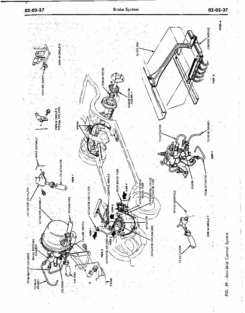
. -
- .
-
--
.
. .
FIG
. 39
-An
ti-S
kid
C
on
tro
l S
yste
m
. ..
VIEW
U
2. Disconnect the actuator solenoid and warning switch harness connectors from the control module. 3. Remove the two wiring harness
grommets from the dash panel and push the wiring harness and connec- tors through the openings in the dash panel.
4. Working in the engine compart- ment loosen the hose clamp and re- move the air hose from the'air filter. 5. Remove the engine air cleaner.
Loosen the hose clamp and remove the vacuum hose from the vacuum manifold fitting.
6. Raise the vehicle on a ,hoist. 7. Disconnect the exhaust pipes
from the exhaust manifold and sup- port with wire to provide access to the actuator assembly.
8. Remove the, bolt retaining the actuator ground wire to the rear outer corner of the engine right bank.
9. Loosen the tube nuts and discon- nect the brake system hydraulic tubes from the hydraulic valve housing. 10. Remove the three nuts retaining
the actuator assembly to the actuator support bracket.
11. Remove the three bolts that re- tain the actuator mounting bracket to the side rail and remove the mounting bracket. 12. Remove the actuator assembly
from the vehicle and place it on a bench. 13. Remove the air and vacuum
hoses from the actuator.
INSTALLATION
I. Install the air and vacuum hoses on the new actuator. 2. Place the actuator assembly into
position under the vehicle, routing the air and vacuum hoses up between the engine and fender apron and inserting the solenoid leads through the holes in the firewall.
3. Position the ground wire to the rear of the engine block and install re- taining bolt.
4. Position the actuator mounting bracket to the frame side rail and in- stall the three retaining bolts.,
5. Position the actuator assembly to the mounting bracket and install the three retaining nuts.
6. Connect the hydraulic tubes to the hydraulic valve assembly and tighten the tube nuts to specifications.
7. Connect the exhaust pipes to the exhaust manifolds.
8. Lower the vehicle. 9. Pull the actuator solenoid and
brake warning switch wiring harness
through the two holes in the dash panel from inside the car. Seat the wiring harness grommets in the dash panel. 10. Connect the actuator solenoid
and brake warning switch wiring har- ness connectors to the control mo- dules.
11. Position the control module in the bracket under the glove box and install the retaining screw. 12. In the engine compartment con-
nect the air hose to the air filter and position the hose clamp.
13. Connect the vacuum hose to the engine vacuum manifold fitting. In- stall the engine air cleaner. 14. Bleed the rear brake system and
centralize the pressure differential valve. 15. Raise the rear wheels. Apply
the brakes with the rear wheels turn- ing to verify proper operation of the anti-skid control system.
ANTI-SKID CONTROL MODULE
REMOVAL
Refer to Fig. 39. 1, Remove the retaining strap hold-
ing the harnesses. 2. Remove the screw that attaches
the forward end of the control module retainei to the support assembly.
3. Lower the forward end, of the control module and retainer from the support assembly; move the module and retainer forward slightly until the flange clears the slot in the support assembly.
4. Disconnect the five wiring har- ness plugs from the control module. 5. Remove the control module from
the vehicle.
INSTALLATION
1. Connect the five wiring harness plugs to the control module. Only one arrangement is possible. 2. Position the control module in
the retainer, orienting the module per the markings on it, and insert the re- tainer flange into the slot a t the rear of the support assembly.
3. Pivot the retainer and control module upward and align the screw hole in the forward end of the retainer with the hole in the support bracket assembly. Install the retaining screw.
4. Test the vehicle on the hoist to verify correct operation of the skid control system.
5.. Secure the wiring to the module support extension with the retaining strap.
ANTI-SKID CONTROL SENSOR
REMOVAL
Refer to Fig. 39. 1. Raise the vehicle on a hoist. 2. Remove the rear wheel and tire
assembly. 3. Remove the three Tinnerman
nuts (3) and remove the brake drum. 4. Disconnect the sensor lead from
the rear wiring harness. 5. Unseat the sensor lead grommet
pushing it to the inside of the brake assembly.
6. Remove the four nuts that retain the sensor to the backing plate and pull the axle shaft, sensor assembly and wheel bearing assembly from the axle housing.
7. Press the wheel bearing retainer and wheel bearing off the axle shaft (Refer to Part 4-2).
8. Remove the sensor assembly and press the rotor off the shaft with tool T69P-2B384-A Detail 2 and ' TOOL 1225-DA.
INSTALLATION
1. Press a new rotor onto the axle shaft. Install a new sensor assembly o n t h e s h a f t w i t h t o o l T 6 9 P - 2B384-ADetail I and TOOL 1225- DA, and press the bearing and bear- ing retainer onto the shaft (Refer to Part 4-2). * 2. Insert the axle shaft assembly in
the rear axle housing onto the four backing plate retaining bolts, feeding , the sensor lead through the hole in the backing plate.
3. Seat the sensor lead grommet in the backing plate.
4. Install the four nuts on the re- taining bolts and tighten to specifica- tions. 5. Connect the sensor lead to the
rear wiring harness and install two re- taining straps.
6. Initall the rear brake drum and retain with the Tinnerman drum re- taining nuts.
7. Install the rear wheel and tire as- sembly and tighten the wheel nuts to specifications.
8. Test the vehicle on the hoist to verify proper operation of the skid control system.
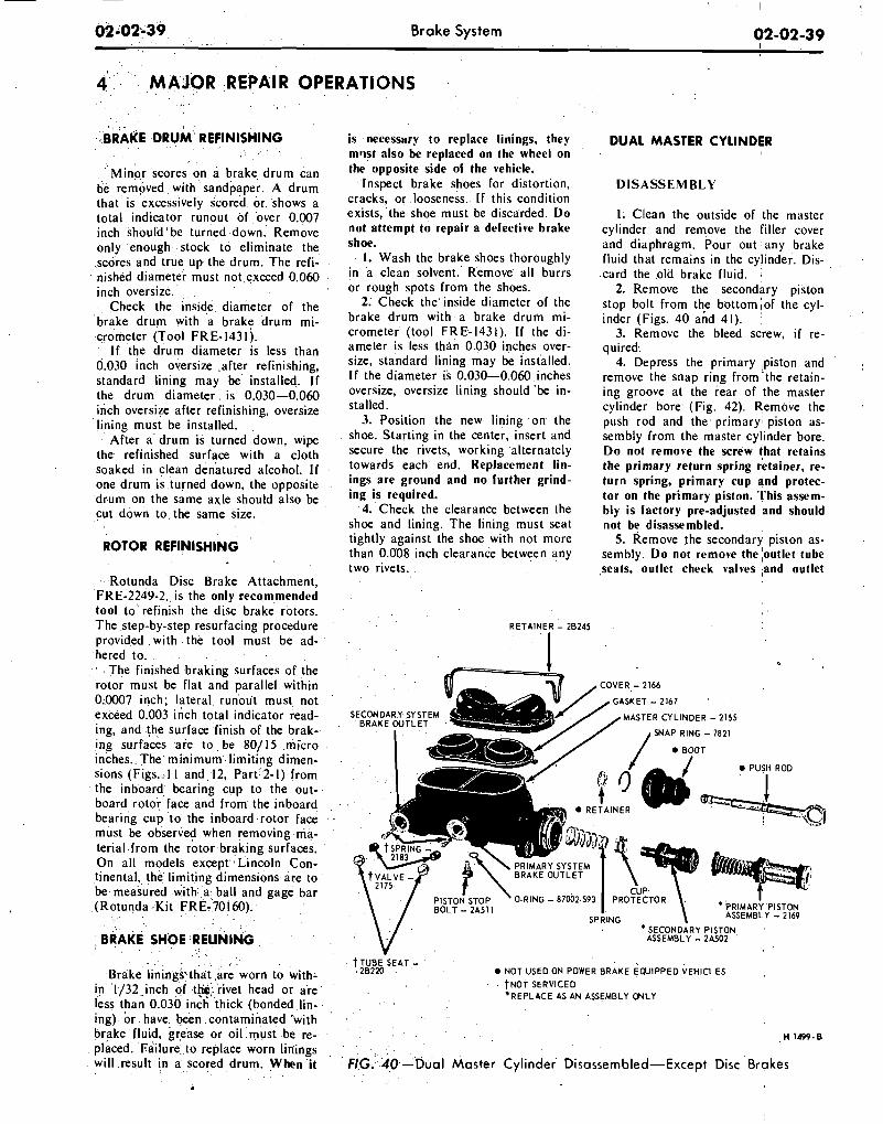
I
02-02-39 Brake System 02-02-39
4 MAJOR REPAIR OPERATIONS
Minor scores on a brake drum can be removed with sandpaper. A drum that is excessively scored or shows a total indicator runout of over 0.007 inch should'be turned down. Remove only enough stock to eliminate the scores and true up the drum. The refi- nished diameter must not exceed 0.060 inch oversize.
Check the inside diameter of the brake drum with a brake drum mi- crometer (Tool FRE- 143 l).
If the drum diameter is less than 0.030 inch oversize .after refinishing, standard lining may be installed. If the drum diameter is 0.030-0.060 inch oversize after refinishing, oversize lining must be installed.
After a drum is turned down, wipe the refinished surface with a cloth soaked in clean denatured alcohol. If one drum is turned down, the opposite drum on the same axle should also be cut down to the same size.
ROTOR REFINISHING
Rotunda Disc Brake Attachment, FRE-2249-2, is the only recommended tool to refinish the disc brake rotors. The step-by-step resurfacing procedure provided wlth the tool must be ad- hered to.
The finished braking surfaces of the rotor must be flat and parallel within 0.0007 ~nch ; lateral runout must not exceed 0.003 inch total indicator read- ing, and the surface finish of the brak- Ing surfaces are to be 80/15 micro Inches. The minimum limiting dimen- slons (Figs. 1 1 and 12, Part 2- 1) from the Inboard bearing cup to the out- board rotor face and from the inboard bearing cup to the inboard rotor face must be observed when removing ma- terial from the rotor braking surfaces. On all models except Lincoln Con- tinental, the limiting dimensions are to be measured with a ball and gage bar (Rotunda Kit FRE-70160).
BRAKE SHOE RELINING
is necessary to replace linings, they m w t also be replaced on the wheel on the opposite side of the vehicle.
Inspect brake shoes for distortion, cracks, or looseness. I f this condition exists, the shoe must be discarded. D o not attempt to repair a defective brake shoe.
1. Wash the brake shoes thoroughly in a clean solvent. Remove all burrs or rough spots from the shoes.
2. Check the inside diameter of the brake drum with a brake drum mi- crometer (tool FRE-1431). If the di- ameter is less than 0.030 inches over- size, standard lining may be installed. If the diameter is 0.030-0.060 inches oversize, oversize lining should 'be in- stalled.
3. Position the new lining on the shoe. Starting in the center, insert and secure the rivets, worklng alternately towards each end. Replacement lin- ings are ground and no further grind- ing is required.
4. Check the clearance between the shoe and lining. The lining must seat tightly against the shoe with not more than 0.008 inch clearance between any two rivets.
R E T A I N E R - 28245
SECONDARY SYSTEM BRAKE OUTLET
DUAL MASTER CYLINDER I
D I S A S S E M B L Y
I. Clean the outside of the master cylinder and remove the filler cover and diaphragm. Pour out any brake fluid that remains in the cylinder. Dis-
,
.card the .old brake fluid. 2. Remove the secondary piston
stop bolt from the bottom;of the cyl- ,
inder (Figs. 40 and 41). ' 3. Remove the bleed screw, i f re-
quired: 4. Depress the primary ;piston and I
remove the snap ring from the retain- ing groove at the rear of ,the master cylinder bore. (Fig. 42). Remove the push rod and the. primary; piston as- sembly from the master cylinder bore. D o not remove the screw that retains the primary return spring retainer, re- turn spring, primary cup and protec- tor on the primary piston. 'This assem, bly is factory pre-adjusted and should not be disassembled.
5. Remove the secondary piston as- sembly. D o not remove the ;outlet tube ,seats, outlet check valves ,and outlet
COVER - 2166
/ G A S K E T - 2 1 6 7 '
f l / / B O O T
0 ifd PUSH ROD
t R E T A I N E R
\ / PISTO; STOP ' O-RING - 87002.593 PRO?;~TOR I I BOLT - 2A5 1 1 ' P R I M A R Y PI
SPRING ASSEMBLY - - .. .
' S E C O N D ~ R Y PISTON, : ASSEMBLY - 2A502
Brake linings that are worn to wit,,- in 1/32 inch of t&,.rivet head or are less than 0.030 inch thick (bonded lin-
t TUBE-SEAT - Brake linings that are worn to with- 20220 NOT USED ON POWER B R A K E ECUIPPED VEHICLES
in 1/32 inch of t&,.rivet head or are NOT SERVICED 'REPLACE AS AN ASSEMBLY ONLY
less than 0.030 inch thick (bonded lin-
NOT SERVICED 'REPLACE AS AN ASSEMBLY ONLY
ing) or have been contaminated "with brake fluid, grease or oil must be re- H 1499.8 placed. Failure to replace worn linings will result in a scored drum. When i t FIG. 40-Dual Master Cylinder Disassembled-Except Disc Brakes
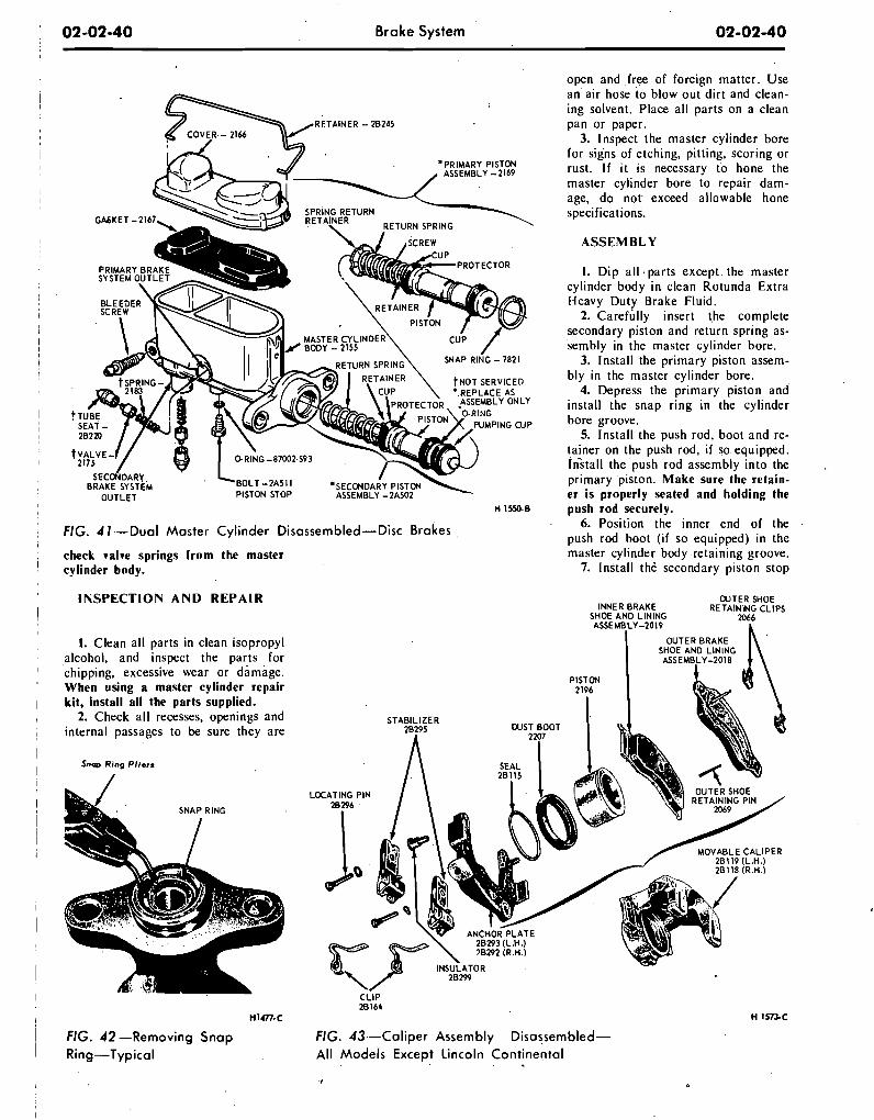
02-02-40 Brake System 02-02-40
FIG. 41-Dual Mas te r Cyl inder Disassembled-Disc rakes check valve springs f rom the master cylinder body.
I N S P E C T I O N A N D R E P A I R
I. Clean al l parts in clean isopropyl alcohol, and inspect the parts for 'chipping, excessive wear or damage. When using a master cylinder repair kit, install al l the parts supplied.
2. Check al l recesses, openings and internal passages to be sure they are
Snq, Ring Pl iers
open and free of foreign matter. Use an air hose to blow out d i r t and clean- ing solvent. Place al l parts on a clean pan or paper.
3. Inspect the master cylinder bore for signs of etching, pitting, scoring or rust. I f i t is necessary to hone the master cylinder bore to repair dam- age, do not exceed allowable hone specifications.
A S S E M B L Y
I. D i p a l l parts except the master cylinder body i n clean Rotunda Extra Heavy Duty Brake Fluid.
2. Careflilly insert the complete secondary piston and return spring as- sembly in the master cylinder bore.
3. Install the primary piston assem- bly in the master cylinder bore.
4. Depress the primary piston and' install the snap r ing i n the cylinder bore groove.
5. Install the push rod, boot and re- tainer on the push rod, i f so equipped. Install the push rod assembly into the primary 'piston. Make sure the retain- er is properly seated and holding the push rod securely.
6. Position the inner end o f the push rod boot ( i f so equipped) i n the master cylinder body retaining groove.
7. Install th6 secondary piston stop
CUTER SHOE INNER BRAKE RETAINING CLIPS
SHOE AND LINING 2066 ASSEMBLY-2019 L
I OUTER BRAKE SHOE AND LINING ASSEMBLY-POI8
STABILIZER
-0CATING PIN
JQ -.
CLIP 28164
n1m-c
FIG. 42 -Removing S n a p FIG. 43--Cal iper Assembly-Disassembled-
Ring-Typical A l l Mode ls Except Lincoln Cont inenta l . .
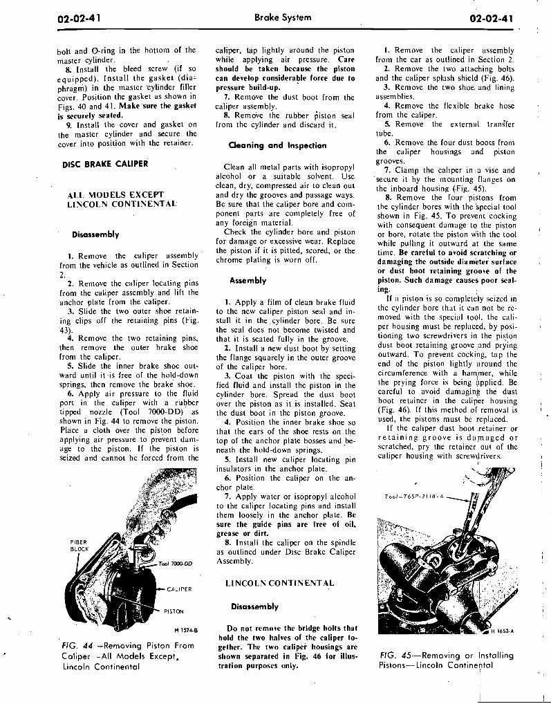
bolt and.0-r ing in the bottom of the master cylinder.
8. Install the bleed screw (if so equipped) . Install the gasket (dia: phragm) in the master 'cylinder filler cover. Position the gasket as shown in Figs. 40 and 4 1 . Make sure the gasket is securely seated.
9. install the cover and gasket on the master cylinder and secure the cover into position with the retainer.
ALL MODELS EXCEPT LINCOLN CONTINENTAL
Disassembly
1. Remove the caliper assembly from the vehicle as outlined in Section 2.
2. Remove the caliper locating pins from the caliper assembly and lift the anchor plate from the caliper.
3. Slide the two outer shoe retain- ing clips off the retaining pins (Fig. 43).
4. Remove the two retaining pins, then remove the outer brake shoe from the caliper.
5. Slide the inner brake shoe out- ward until it is free of the hold-down springs, then remove the brake shoe.
6. Apply air pressure to the fluid port in the caliper with a rubber tipped nozzle (Tool 7000-DD) as shown in Fig. 44 to remove the piston. Place a cloth over the piston before applying air pressure to prevent dam- age to the piston. If the piston is seized and cannot be forced from the
CALIPER
FIG. 4 4 -Removing Piston Fiom Coliper-All Models Except, Lincoln Continental
Brake System
caliper, tap lightly around the piston while applying air pressure. Care should be taken because the piston can develop considerable force due to pressure build-up.
7. Remove the dust boot from the caliper assembly.
8. Remove the rubber ;iston seal from the cylinder and discard it.
Cleaning a n d Inspection
Clean all metal parts with isopropyl alcohol or a suitable solvent. Use clean, dry, compressed air to clean out and dry the grooves and passage ways. Be sure that the caliper bore and com- ponent parts are completely free of any foreign material.
Check the cylinder bore and piston for damage or excessive wear. Replace the piston i f it is pitted, scored, or the chrome plating is worn off.
Assembly
1. Apply a film of clean brake flu~d to the new caliper piston seal and in- stall it in the cylinder bore. Be sure the seal does not become twisted and that it is seated fully in the groove.
2. Install a new dust boot by setting the flange squarely in the outer groove of the caliper bore.
3. Coat the piston with the speci- fied fluid and install the piston in the cylinder bore. Spread the dust boot over the piston as it is installed. Seat the dust boot in the piston groove.
4. Position the inner brake shoe so that the ears of the shoe rests on the top of the anchor plate bosses and .be- neath the hold-down springs.
5. Install new caliper locating pin insulators in the anchor plate.
6. Position the caliper on the an- chor plate.
7. Apply water or isopropyl alcohol to the caliper locating pins and install them loosely in the anchor plate. Be sure the guide pins are free of oil, grease or dirt.
8. Install the caliper on the spindle as outlined under Disc Brake Caliper Assembly.
LINCOLN CONTINENTAL
Disassembly
Do not remove the bridge bolts that hold the two halves of the caliper to- gether. The two caliper housings are shown separated in Fig. 46 for illus- tration purposes only.
1. Remove the caliper assembly from the car as outlined in Section 2.
2. Remove the two attaching bolts and the caliper splash shield (Fig. 46).
3. Remove the two shoe. and lining assemblies.
4. Remove the flexible brake hose from the caliper.
5. Remove the external trans'fer tube.
6. Remove the four dust boots from the caliper housings and piston grooves.
7. Clamp the caliper in la vise and , 'secure it by the mounting flanges on the inboard housing (.Fig. 45).
8. Remove the four pistons from , the cylinder bores with the 'special tool shown in Fig. 45. To prevent cocking with consequent damage to the piston , or bore, rotate the piston with the tool while pulling it outward at the same time. Be careful to avoid scratching or damaging the outside diamktei surface or dust boot retaining grooke of the piston. Such damage causes poor seal- ing.
I f a piston is so completely seized In the cylinder bore that it can not be rc- moved with the special tool, the cali- per housing must be replaced, by posi- tioning two screwdrivers in the piston dust boot retaining groove jand prying , outward. To prevent cocking, tap the end of the piston lightly around the circumference with a ham,mer, while the prying force is being Gpplied. Be careful to .avoid damaging the dust boot retainer in the caliper housing , (Fig. 46). I f this method or; removal is I
used, the pistons must be replaced. I f the caliper dust boot ,retainer or ,
r e t a i n i n g g r o o v e is d a m a g e d o r i scratched, pry the retainer out of the '
caliper housing with screwdrivers.. I
I
FIG. 45--Removing o r Instolling Pistons-Lincoln Continental
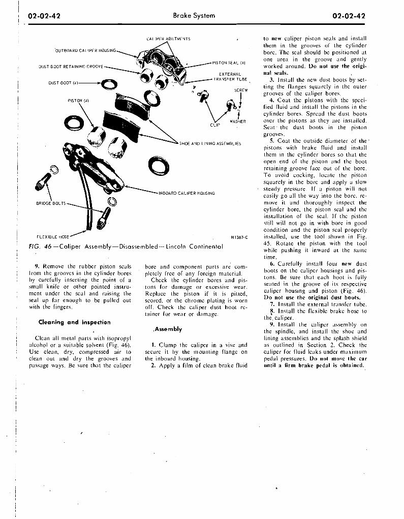
I
1 02-02-42 Brake System 02-02-42 I .
CALIPER ABUTMENTS
OUTBOARD CALIPER HOUSING
PISTON SEAL ( A ) DUST BOOT RETAINING GROOVE
CXTERNAL
OUST
TRANSFER TUBE
SHOE A N 0 LINING ASSEMBLIES
0
9 INBOARD CALIPER HOUSING
BRIDGE BOLTS
FIG. 46 -Ca l i pe r Assembly-Disassembled-Lincoln C o n t i n e n t a l
9. Remove the rubber piston seals f rom the grooves i n the cylinder bores by carefully inserting the point o f a small kni fe or other pointed instru- ment under the seal and raising the seal up far enough to be pul led out with the fingers.
Cleaning a n d Inspection
Clean a l l metal parts wi th isopropyl alcohol or a suitable solvent (Fig. 46). Use clean, dry, compressed air to clean out and d ry the grooves and passage ways. Be sure that the caliper
bore and component parts are com- pletely free o f any foreign material.
Check the cylinder bores and pis- tons fo r damage o r excessive wear. Replace the piston i f i t is pitted. scored, or the chrome plat ing is worn of f . Check the caliper dust boot re- tainer for wear or damage.
. Asse r n bl y
I. Clamp the caliper i n a vise and secure i t by the mount ing flange on the inboard housing.
2. App ly a f i lm o f clean brake f lu id
to new caliper piston seals and install them i n the grooves o f the cylinder bore. The seal should be positioned at one area i n the groove and gently worked around. D o not use the origi- nal seals.
3. Instal l the new dust boots by set- t ing the flanges squarely in the outer grooves of the caliper bores.
4. Coa t the pistons wi th the speci- fied f lu id and install the pistons i n the cylinder bores. Spread the dust boots over the pistons as they are installed. Seat. the dust boots in the piston grooves.
5. Coat the outside diameter o f the . pistons w i th brake f lu id and install them i n the cylinder bores so that the open end of the piston and the boot retaining groove face out o f the bore. T o avoid cocking, locate the piston squarely in the bore and apply a slow steady pressure. I f a piston w i l l not easily go a l l the way in to the bore, re- niove i t and thoroughly inspect the cylinder bore, the piston seal and the installation o f the seal. I f the piston st i l l w i l l not go i n w i th bore in good condi t ion and the piston seal proper ly installed, use the tool shown i n F ig . 45. Rotate the piston with the tool while pushing i t inward at the same time.
6. Careful ly install four new dust boots on the caliper housings and pis- tons. Be sure that each boot is fu l ly seated i n the groove o f i ts respective caliper housing and piston (Fig. 46). Do not use the original dust hoots.
7. Instal l the external transfer tube. 8. Instal l the f lexible brake hose to
the. caliper. 9. Instal l the caliper assembly on
the spindle. and install the shoe and l in ing assemblies and the splash shield as outl ined i n Section 2. Check the caliper for f lu id leaks under m a x i m u m pedal pressures. D o not move the car until a firm brake pedal is ohtained.
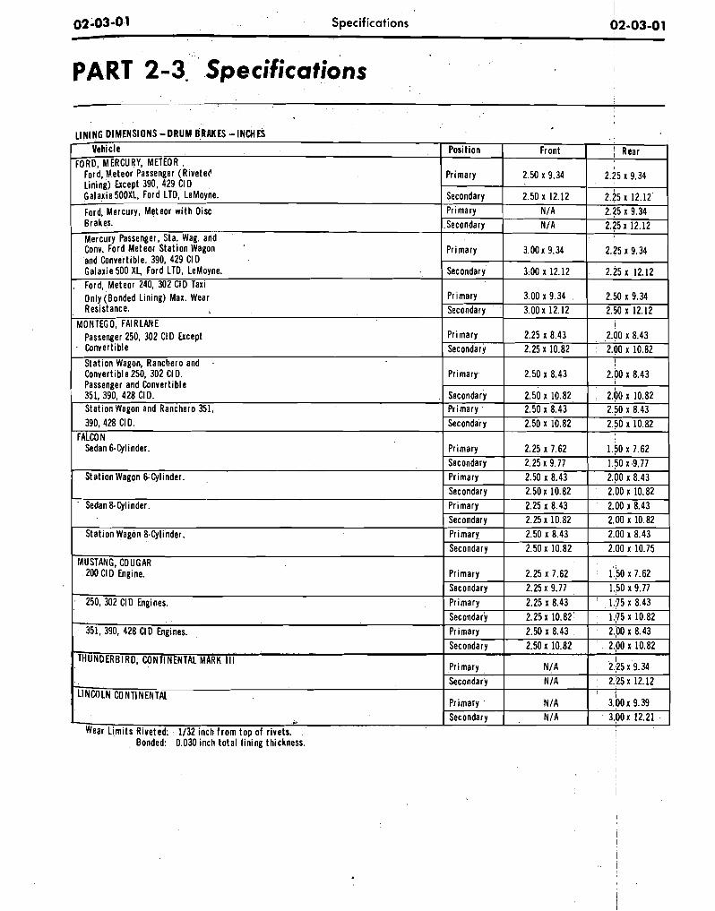
02-03-0 1 Specifications I 02-03-01 !
PART 2-3. ' Specifications
Bonded: 0.030 inch t o ta l l in ing thickness.
LINING DIMENSIONS -DRUM BRAKES -INCHES Vehicle
FORD, MERCLIRY, METEOR Ford, Meteor Passenger (RiveteC Lining) Except 390, 429 CID Galaxie 500XL, Ford LTD, LeMoyne.
Ford, Mercury, Meteor w i t h O i x Brakes.
Mercury Passenger, Sta. Wag. and Conv. Ford Meteor Stat ion Wagon *
and Convertible. 390, 429 CID Galaxie 500 XL, Ford LTD, LeMoyne. . Ford, Meteor 240, 302 CID Taxi Only (Bonded Lining) Max. Wear Resistance.
MONTEGO, FAIRLANE Passenger 250, 302 CI D Except Convert~ble
Stat ion Wagon, Ranchero and . Convert~ble 250, 302 CI D. Passenger and Convertible 351, 390, 428 CI D. Station Wagon and Ranchero 351, 390,428 CI D.
FALCON Sedan 6-Cylinder.
Stat ion Wagon 6-Cylinder.
- Sedan 8-Cylinder.
Stat ion Wagon 8-Cylinder.
MUSTANG, COLIGAR 200 Cl D Engine.
250, 302 CI D Engines.
351, 390, 428 Cl D Engines.
THUNDERBIRD, CONTINENTAL MARK Ill
LINCOLN CONTINENTAL
i
Wear L im i t s Riveted: 1/32 inch f r om to^ of rivets.
Position
Primary
Secondary Primary Secondary
Primary
Secondary
Pr~mary Secondary
Primary Secondary
Pr~mary
Secondary Primary Secondary
Primary Secondary P r~mary Secondary P r~mary Secondary Primary Secondary
Primary Secondary Primary Secondary Primary Secondary
Primary Secondary
Primary Secondary
Front
2.50 x 9.34
2.50 x 12.12 N/A N/A
3.00 x 9.34
3.00 x 12.12
3.00 x 9.34 3 OOx 12.12
2.25 x 8.43 2.25 x 10.82
2.50 x 8.43
2.50 x 10.82 2.50 x 8.43 2.50 x 10.82
2.25 x 7.62 2.25 x 9.77 2.50 x 8.43 2.50 x 10.82 2.25 x 8.43 2.25 x 10.82 2.50 x 8.43 2.50 x 10.82
2.25 x 7.62 2.25 x 9.77 2.25 x 8.43 2.25 x 10.82 2.50 x 8.43 2.50 x 10.82
N/A NIA
N/A N/A
( Rear
2.25 x 9.34
2.25 x 12.12 2.25 x 9.34 2.25 x 12.12
I
2.25 x 9.34
2.25 x 12.12
2.50 x 9.34 2.50 x 12.12
I 2.00 x 8.43 2.00 x 10.82
I 2.00 x 8.43
I
2.00 x 10.82 2.50 x 8.43 2.50 x 10.82
1.50 x 7.62 1.50 x 9.77 2.00 x 8.43
' 2.00 x 10.82 2.00 x 8.43 2.00 x 10.82 2.00 x 8.43 2.00 x 10.75
I 1.50 x 7.62 1.50 x 9.77
' 1.175 x 8.43 1.175 x 10.82 2.00 x 8.43 2.00 x 10.82
I 2.25 x 9.34 2.25 x 12.12
1
3 . 0 0 ~ 9.39 3 . 0 0 ~ 12.21
I
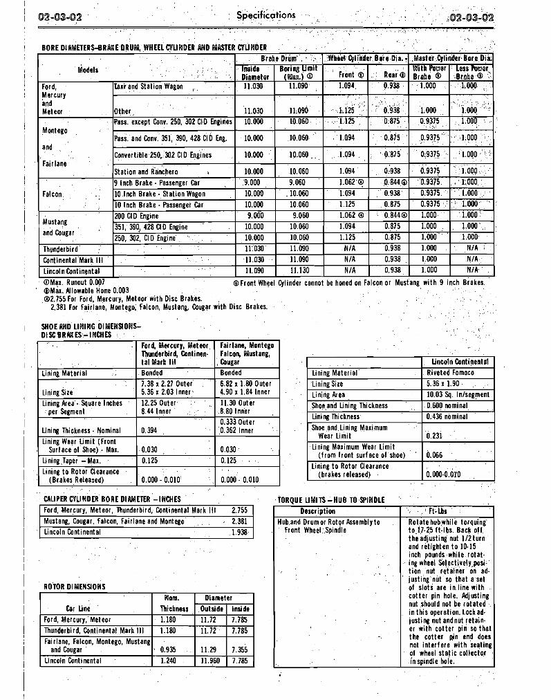
CALIPER CYLINDER BORE DlaWlETER -INCHES Ford, Mercury, Meteor, Thunderbird, Continental Mark 111 2.755 Mustang, Cougar, Falcon, Fairlane and Montego 2.381
I I
I
I : I
I I ' 1 I I I 1
1 1 I 1 1
/ 1
I Lincoln Continental 1.938 1
ROTOR DlMEsJSlOWS
1 @Max. Allowable Hone 0.003 02.755 For Ford, Mercury, Meteor w i th Disc Brakes.
2.381 For Fairlane, Montego, Falcon, Mustang, Cougar w i th Disc Brakes.
I SHOE AND LlNlWG DIMENSIONS-
I Thunderbird, Continental Mark Ill 1.180 . 1 11.72 1 7.785 1
@Max. Runout 0.007 @Front Wheel Cylinder cannot be honed on Falcon or Mustang w i t h 9 inch Brakes.
Master Qlinder.Eore Dia: BORE DIAMETERS-BRAKE DRUM, WHEELCYUWDER AND MASTER
Models
Car Line Ford, Mercury, Meteor
W i th Power B r i b e
1.000
1.000 0.9375
0.9375 '
0.9375
0.9375 0.9375 0.9375 0.9375 1.000 1.000 1.000 '
1.000 1.000 1.000
Ford, Mercury and Meteor
Montego
and
Fair lane
Falcon
Mustang and Cougar
Thunderbird Continental Mark Ill Lincoln Continental
1 Llncoln Continental 1 1.240
Less w ~ r B~~~:@
1.000
l.Ob0 1.000
1.000 .
1.000
1.000,, , 1.000
1.000 1.000 1.000 1.000 1.000
N/A N /A NIA
CYLINDER Brohe Drum' . '
Taxi and Station Wagon
Other Pass. except Conv. 250, 302 CID Engines
Pass. and Conv. 351, 390, 428 ClD Eng.
Convertible 250, 302 ClD Englnes
Stat ion and Ranchero , 9 Inch Brake - Passenger Car 10 Inch Brake - Stat ion Wagon 10 Inch Brake - Passenger Car 200 CID Engine 351, 390J 428 CIO Engine 250, 302, CID Engine
Wom. Thickness 1.180
I I
Whe'el Qli'nder Bore Dia. 0
Inside Diameter 11.030
11.030 10.000
10.000
10.000
10.000 9.000 10.000 10.000 9.000
10.000 10.000 11.030 11.030 11.090
Diameter Outside I Inside 11.72 1 7.785
Fair lane, Falcon, Montego, Mustang and Cougar '
~ r o n t 0 1.094
- 1.125 1.125
1.094
1.094
1.094 1.062 9 1.094 1.125 1.062 0 1.094 1.125
N/A N /A N/A
Boring L imi t ( h a ) @
11.090
11.090 10.060
10.060
10.060
10.060 9.060
. 10.060 10.060 9.060
10.060 10.060 11.090 11.090 11.130
TORQUE LIMITS-HUB TO SPINDLE
1.11 0 0.938
>
' 0.938 0.875
0.875
0.875
0.938 0.8440 0.938 0.875 0.8440 0.875 0.875 0.938 0.938 0.938
Descript ion Hub and Drumor Rotor Assembly t o
Front Wheel Spindle
, 0.935
Ft-Lbs Rotatehubwhi le torquing t o 17-25 ft-lbs. Back o f f t he adjusting nut 112turn and retighten t o 10.15 inch pounds while ro ta t - Ing wheel Selectively posi- t i on nut retainer on ad- just ing nut so t ha t a set of s lots are i n l ine wi th cot ter pin hole. Adjusting nut should not be ro ta ted i n th is operation. Lockad- lust ing nut andnut retain- er w i th cot ter p in so that the cot ter pin end does not in ter fere w i t h seatinp of wheel s ta t i c col lector i n spindle hole.
11.29 7.355
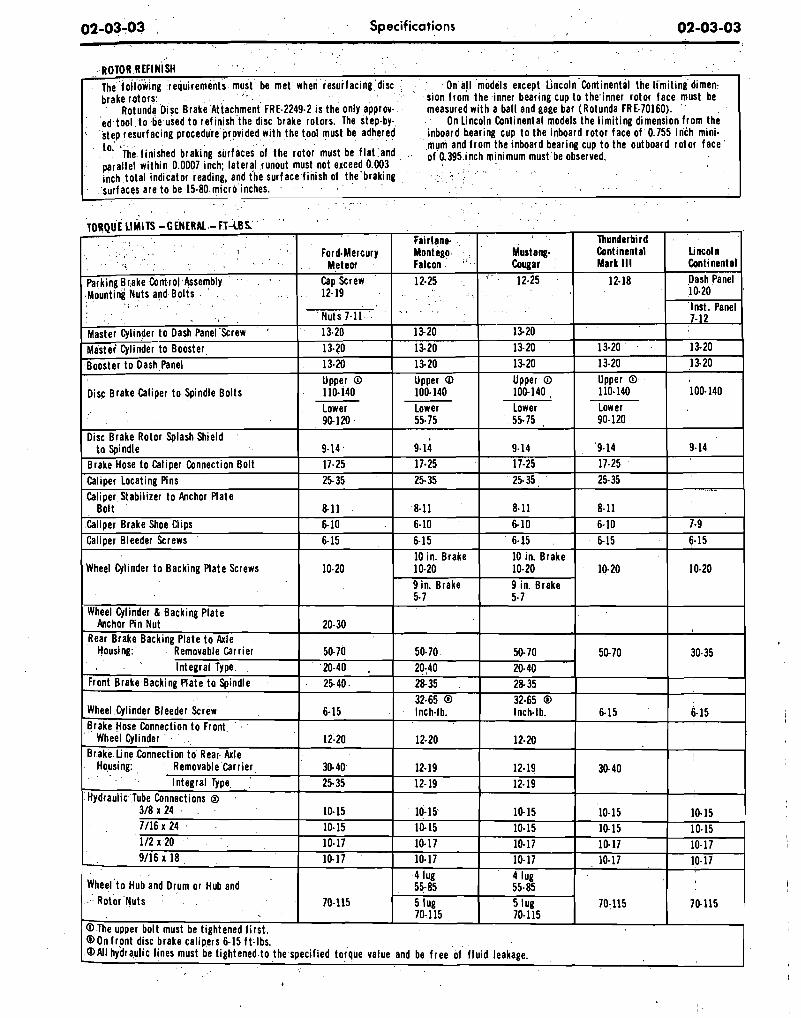
02-03-03 Specifications 02-03-03
ROTOR REFINISH
I The following requirements must be met when resurfacing disc brake rotors:
Rotunda Oisc Brake Attachment FRE-2249-2 is the only approv- ed tool t o -be used t o refinish the disc brake rotors. The step-by- step resurfacing procedure provided with the tool must be adhered to. The finished braking surfaces of the rotor must be f la t and parallel within 0.0007 inch; lateral runout must not exceed 0.003 Inch total indicator reading, and the surface finish of the braking surfaces are to be 15.80 micro Inches.
On al l models except Lincoln Continental the l imi t ing dimen- sion from the inner bearing cup to the'inner rotor face must be measured with a ball and gage bar (Rotunda FRE-70160). '
On Lincoln Continental models the l imit ing dimension from the inboard hearing cup t o the inboard rotor face of 0.755 inch mini- mum and from the inboard bearing cup t o the outboard rotor face of 0.395 inch minimum must be observed.
I I
I
I
Lincoln Continental Dash Panel 10.20 Inst. Panel 7-12
13- 20 13-20
100-140
9.14
-
7.9 6-15
10-20
30-35
6-15
:
10.15 10-15 10-17 10-17
70.115
@All hydraulic lines must be tightened to the specified torque value and be free of f l u ~ d leakage.
Thunderbird Cont inental Mark Ill
12-18
13-20 13-20 Upper O 110-140 Lower 90-120
9-14 17-25 25- 35
8-11 6-10 6 15
10.20
50- 70
6.15
30- 40
10-15 10-15 10-17 10-17
70-115
Mustang- Cougar
' 12-25
1520 13-20 13.20 Upper O 100-140 Lower 55- 75
9-14 17-25 25- 35
8.11 6-10 6-15 10 in. Brake 10-20 9 ~ n . Brake 5- 7
50- 70 20-40 2 8 35 32.65 0 Inch-lb.
12-20
12-19 12-19
10-15 10-15 10-17 10-17 4 lug 55- 85 5 lug 70-1 15
Fair lane. Montego Falcon 12-25
1520 13-20 13-20 Upper O 100- 140 Lower 55.75
9.14 17-25 25-35
8-11 6- 10 6-15 10 in. Brake 10-20 9 in. Brake 5- 7
50-70 20-40 2835 32-65 0 Inch-lb.
12-20
12-19 12- 19
10-15 10-15 10- 17 10-17 4 lug 55-85 5 lug 70-1 15
TORQUE LIMITS -GENERAL -FT-LBS '
Parking Brake Control Assembly - Mounting Nuts and Bolts
, a
Master Cyl~nder t o Oash Panel Screw Master Cylinder to Booster Booster to Dash Panel
Disc Brake Caliper t o Spindle Bolts
Oisc Brake Rotor Splash Shield to Spindle
Brake Hose to Callper Connect~on Bolt Callper Locating Pins Caliper Stablllzer to Anchor Plate
Bolt Caliper Brake Shoe Cl~ps Caliper Bleeder Screws
Wheel Cylinder t o Backing Plate Screws
Wheel Cylinder & Back~ng Plate Anchor Pin Nut
Rear Brake Backlng Plate t o Axle Housing. Removable Carr~er
Integral Type Front Brake Backing Plate t o Spindle
Wheel Cylinder Bleeder Screw Brake Hose Connection t o Front
Wheel Cylinder Brake tine Connection to Rear Axle
Housing. Removable Carrier Integral Type
Hydraulic Tube Connections Q 318 x 24 7/16 x 24 112 x 20 9/16 1 18
Wheel t o Hub and Drum or Hub and Rotor Nuts
@On front disc brake calipers 6-15 ft-lbs.
Ford-Mercury Meteor
Cap Screw 12- 19
Nuts 7-11 13.20 13-20 13-20 Upper O 110-140 Lower 90-120
9-14. 17.25 25- 35
8 1 1 6-10 6-15
10-20
20-30
50-70 20-40 . 25-40
6-15
12-20
30- 40 25-35
10-15 10-15 10-17 10-17
70-115
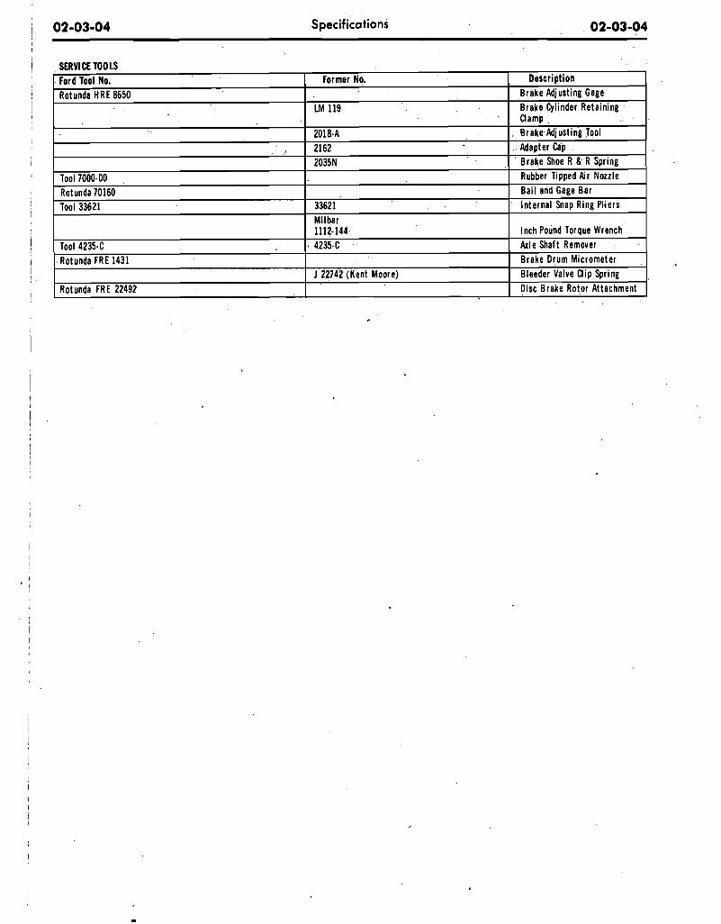
I
i 02-03-04 Specifications 02-03-04
1 SERVl CE TOOLS
1 1112-144 I Inch Pound Torque Wrench I I Tool 4 2 3 5 4 1, 4235-C I Axle Shaft Remover
Tool 7000-00 Rotunda 70160 Tool 33621
Descript ion Brake Adjusting Gage Brake Cylinder Retaining
I
i 2018-A 2162 2035N
33621 Milbar
1 I I
Ford Tool No. Rotunda HRE 8650
Clamp , Brake Adjusting Tool
Adapter Cap Brake Shoe R & R Spring
Rubber Tipped Air Nozzle Bal l and Gage Bar Internal Snap Ring Pliers
I
Former No.
LM 119
- - - - Rotunda FRE 1431
Rotunda FRE 22492 I I Disc Brake Rotor Attachment
I I Brake Drum Micrometer J 22742 (Kent Moore) I Bleeder Valve Clip Spring
I
We are a licensed distributor of Adobe Reader
This is only a Demo of the product! Only a few pages are included.
Description: The Ford Shop Manual is the original manual used by the Ford dealership mechanics at to guide them through repairs and maintenance. Each section provides information on the operation of major systems, diagnostics, troubleshooting, overhaul, as well as the removal and installation of major components. Written in an easy to understand format, this manual contains step-by-step instructions designed for the novice and the expert. In addition, this manual is filled with illustrations, photographs, and diagrams that help in the identification of parts and proper assembly.
Adobe Reader: Unlike some CD-ROM versions on the market, this product is produced in Adobe Reader (pdf) format to retain the exact look and feel of the original manual. Simply scroll through the pages and sections like reading a normal printed manual. In addition, unlike a printed version, each page can be printed (or reprinted, if damaged in the garage), zoom in to over 1200% to see
the exact details, and you can search for keywords.
Product Features:
► Printable - Print only the pages you need (if a page is damaged in the shop, just print a new one!) ► Searchable - Search the entire manual in seconds. ► Zoom - Zoom in to over 1200% to see the exact details. ► Transportable - Use on any Windows computer. No additional software needed. ► Bookmarked - Manual is bookmarked to locate sections in seconds. ► Money Back Guarantee!
Our manuals are fully approved and licensed by the Ford Motor Company