Embed Size (px)
Citation preview
Copyright © 2012, Forel Publishing Company, LLC, Woodbridge, Virginia
All Rights Reserved. No part of this book may be used or reproduced in any manner whatsoever without written permission of Forel Publishing Company, LLC. For information write to Forel
Publishing Company, LLC, 3999 Peregrine Ridge Ct., Woodbridge, VA 22192
1976 Ford Truck Shop Manual EAN: 978-1-60371-084-8
ISBN: 1-60371-084-1
Forel Publishing Company, LLC 3999 Peregrine Ridge Ct. Woodbridge, VA 22192
Email address: [email protected] Website: http://www.ForelPublishing.com
This publication contains material that is reproduced and distributed under a license from Ford Motor Company. No further reproduction or distribution of the Ford Motor Company material is
allowed without the express written permission of Ford Motor Company.
NNoottee ffrroomm tthhee PPuubblliisshheerr This product was created from the original Ford Motor Company’s publication. Every effort has been made to use the original scanned images, however, due to the condition of the material; some pages have been modified to remove imperfections.
Disclaimer
Although every effort was made to ensure the accuracy of this book, no representations or warranties of any kind are made concerning the accuracy, completeness or suitability of the information, either expressed or implied. As a result, the information contained within this book should be used as general information only. The author and Forel Publishing Company, LLC shall have neither liability nor responsibility to any person or entity with respect to any loss or damage caused, or alleged to be caused, directly or indirectly by the information contained in this book. Further, the publisher and author are not engaged in rendering legal or other professional services. If legal, mechanical, electrical, or other expert assistance is required, the services of a competent professional should be sought.
FOREWORD
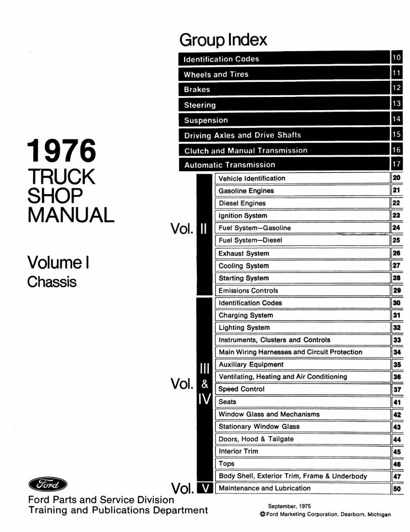
This manual is divided into five volumes: 1 — Chassis, 2 — Engine, 3 — Electrical, 4 —Body, 5 — Pre-delivery, Maintenance and Lubrication. These volumes provide ServiceTechnicians with complete information covering normal service repairs on all 1976 modelvehicles built by the Ford Motor Companies in the U.S. and Canada.
Information in each volume is divided into groups covering a general system. For easyreference, information in each group has been broken into smaller units or parts. There isone part for each component within the system as well as a general service part forinformation common to several similar components. Page numbers indicate this division.
Example: (Group ll-(Part) 02-(Page) 21
Page numbers are consecutive within each part.
The table of contents on the first page of the volume indicates the groups contained in eachof the five volumes, and a tab locator is provided for finding each group of that particularvolume. The first page of each group has an index to the smaller parts, and the first page ofeach part contains an index with page location for each service operation covered.
The descriptions and specifications in this manual were in effect at the time this manual wasapproved for printing. Ford Motor Company reserves the right to discontinue models atany time, or change specifications or design without notice and without incurring obliga-tion.
Ford Parts and Service DivisionTraining and Publications Department
10-00-1 Identification Codes 10-00-1
Identification CodesGROUP
10GENERAL INFORMATIONVEHICLE CERTIFICATION LABEL
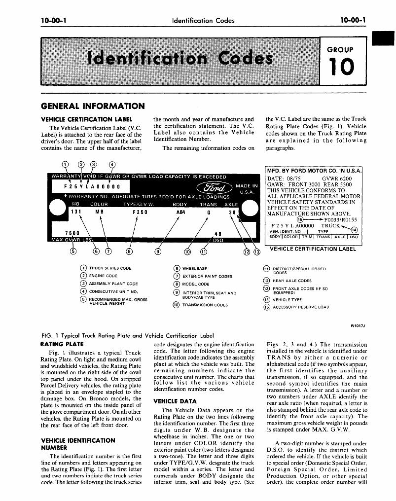
The Vehicle Certification Label (V.C.Label) is attached to the rear face of thedriver's door. The upper half of the labelcontains the name of the manufacturer,
the month and year of manufacture andthe certification statement. The V.C.Label also contains the VehicleIdentification Number.
The remaining information codes on
the V.C. Label are the same as the TruckRating Plate Codes (Fig. 1). Vehiclecodes shown on the Truck Rating Plateare explained in the followingparagraphs.
WARRANTY] VC/ID IF GftWR OR GVWR LOAD CAPACITY IS EXCEEDED
WARRANTY NO. DEQUATE TIRES REQ'D FOR AXLE LOADINGSTYPE/G.V.W
MAX GVn/VR LBS
TRANS AXLE
MFD. BY FORD MOTOR CO. IN U.S.ADATE: 08/75 GVWR 6200GAWR: FRONT 3000 REAR 5300THIS VEHICLE CONFORMS TOALL APPLICABLE FEDERAL MOTORVEHICLE SAFETY STANDARDS INEFFECT ON THE DATE OFMANUFACTURE SHOWN ABOVE.
© ^F0033/R0155F 2 5 Y L A00000 TRUCK
VEH. IDENT.NO I TYPEBODY | COLOR | TRIM | TRANSj AXLE | DSO
® © @ © VEHICLECERTIFICATI0NLABEL
( Y ) TRUCK SERIES CODE
( ? ) ENGINE CODE
( i ) ASSEMBLY PLANT CODE
( J ) CONSECUTIVE UNIT NO.
( i ) RECOMMENDED MAX. GROSSw VEHICLE WEIGHT
® WHEELBASE
( 7 ) EXTERIOR PAINT CODES
( ? ) MODEL CODE
(j)) INTERIOR TRIM, SEAT ANDBODY/CAB TYPE
(i0) TRANSMISSION CODES
(iT) DISTRICT/SPECIAL ORDERw CODES
@ REAR AXLE CODES
( l i ) FRONT AXLE CODES (IF SOW EQUIPPED)
@ VEHICLE TYPE
@ ACCESSORY RESERVE LOAD
FIG. 1 Typical Truck Rating Plate and
RATING PLATEFig. 1 illustrates a typical Truck
Rating Plate. On light and medium cowland windshield vehicles, the Rating Plateis mounted on the right side of the cowltop panel under the hood. On strippedParcel Delivery vehicles, the rating plateis placed in an envelope stapled to thedunnage box. On Bronco models, theplate is mounted on the inside panel ofthe glove compartment door. On all othervehicles, the Rating Plate is mounted onthe rear face of the left front door.
VEHICLE IDENTIFICATIONNUMBER
The identification number is the firstline of numbers and letters appearing onthe Rating Plate (Fig. 1). The first letterand two numbers indiate the truck seriescode. The letter following the truck series
Vehicle Certification Label
code designates the engine identificationcode. The letter following the engineidentification code indicates the assemblyplant at which the vehicle was built. Theremaining numbers indicate theconsecutive unit number. The charts thatfollow list the various vehicleidentification number codes.
VEHICLE DATA
The Vehicle Data appears on theRating Plate on the two lines followingthe identification number. The first threedigits under W.B. designate thewheelbase in inches. The one or twoletters under COLOR identify theexterior paint color (two letters designatea two-tone). The letter and three digitsunder TYPE/G.V.W. desgnate the truckmodel within a series. The letter andnumerals under BODY designate theinterior trim, seat and body type. (See
W1017J
Figs. 2, 3 and 4.) The transmissioninstalled in the vehicle is identified underTRANS by either a numeric oralphabetical code (if two symbols appear,the first identifies the auxiliarytransmission, if so equipped, and thesecond symbol identifies the maintransmission). A letter and a number ortwo numbers under AXLE identify therear axle ratio (when required, a letter isalso stamped behind the rear axle code toidentify the front axle capacity). Themaximum gross vehicle weight in poundsis stamped under MAX. G.V.W.
A two-digit number is stamped underD.S.O. to identify the district whichordered the vehicle. If the vehicle is builtto special order (Domestic Special Order,Foreign Special Order, LimitedProduction Option, or other specialorder), the complete order number will
10-00-2 Identification Codes 10-00-2
also appear under D.S.O. The charts thatfollow list the various vehicle data codes.
W.B. (WHEELBASE)The wheelbase in inches in entered in
this space.
MAX. G.V.W. LBSThe maximum gross vehicle weight in
pounds is recorded in this space.
D.S.O.If vehicle is built on a D.S.O., F.S.O.,
L.P.O. (special orders) the completeorder number will be reflected under theD.S.O. space including the District CodeNumber.
A/ARRANTY VOID IF GAWR OR GVWR LOAD CAPACITY IS EXCEEDED
KKAN I Y NO. ADEQUATE TIRES REQ'D FOR AXLE LOADINGS
B COLOF BODY TRANS AXL
MAX GVWR LBS.
BODY1,1 .1 .1
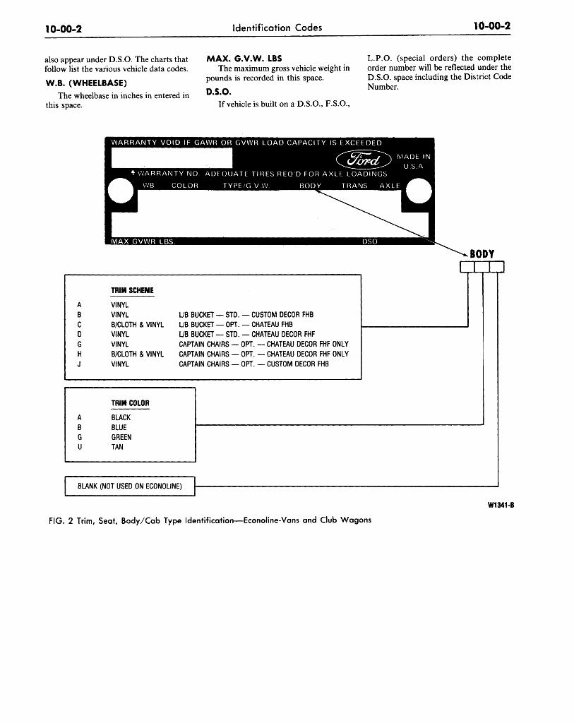
TRIM SCHEME
VINYL
VINYL
B/CLOTH & VINYL
VINYL
VINYL
B/CLOTH & VINYL
VINYL
L/B BUCKET — STD. — CUSTOM DECOR FHB
L/B BUCKET — OPT. — CHATEAU FHB
L/B BUCKET — STD. — CHATEAU DECOR FHF
CAPTAIN CHAIRS — OPT. — CHATEAU DECOR FHF ONLY
CAPTAIN CHAIRS — OPT. — CHATEAU DECOR FHF ONLY
CAPTAIN CHAIRS — OPT. — CUSTOM DECOR FHB
BUNK (NOT USED ON ECONOLINE)
W1341-B
FIG. 2 Trim, Seat, Body/Cab Type Identification—Econoline-Vans and Club Wagons
10-00-3 Identification Codes 10-00-3
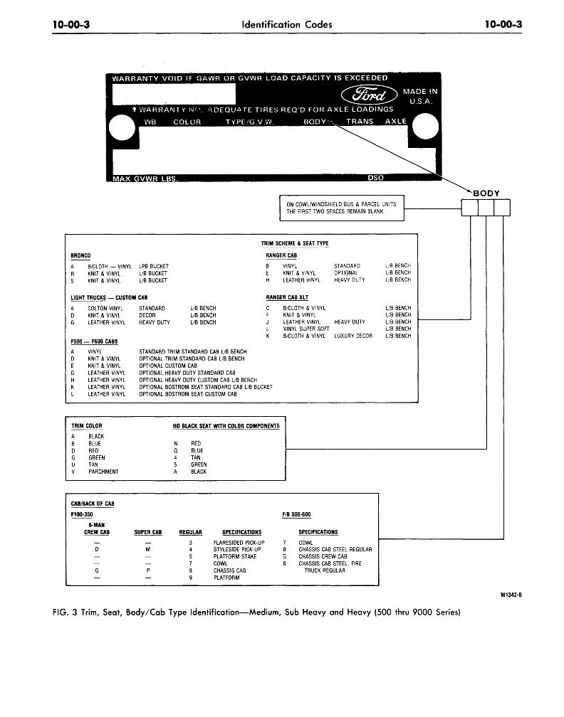
ON COWL/WINDSHIELD BUS & PARCEL UNITS
BRONCO
A B/CLOTH — VINYL LPB BUCKET
R KNIT & VINYL L/B BUCKET
S KNIT & VINYL L/B BUCKET
LIGHT TRUCKS — CUSTOM CAB
A COLTON VINYL STANDARD
D KNIT & VINYL DECOR
G LEATHER VINYL HEAVY DUTY
L/B BENCH
L/B BENCH
L/B BENCH
F500 — F600 CABS
VINYL
KNIT & VINYL
KNIT & VINYL
LEATHER VINYL
LEATHER VINYL
LEATHER VINYL
LEATHER VINYL
TRIM SCHEME & SEAT TYPE
RANGER CAB
B VINYL STANDARD
E KNIT & VINYL OPTIONAL
H LEATHER VINYL HEAVY DUTY
RANGER CAB XLT
B/CLOTH & VINYL
KNIT & VINYL
LEATHER VINYL HEAVY DUTY
VINYL SUPER SOFT
B/CLOTH & VINYL LUXURY DECOR
L/B BENCH
L/B BENCH
L/B BENCH
L/B BENCH
L/B BENCH
L/B BENCH
L/B BENCH
L/B BENCH
STANDARD TRIM STANDARD CAB L/B BENCH
OPTIONAL TRIM STANDARD CAB L/B BENCH
OPTIONAL CUSTOM CAB
OPTIONAL HEAVY DUTY STANDARD CAB
OPTIONAL HEAVY DUTY CUSTOM CAB L/B BENCH
OPTIONAL BOSTROM SEAT STANDARD CAB L/B BUCKET
OPTIONAL BOSTROM SEAT CUSTOM CAB
TRIM COLOR
BLACK
BLUE
RED
GREEN
TAN
PARCHMENT
HD BLACK SEAT WITH COLOR COMPONENTS
RED
BLUE
TAN
GREEN
BLACK
CAB/BACK OF CAB
F100-350
6-MAN
CREW CAB SUPER CAB
M
REGULAR
3457
F/B 500-600
SPECIFICATIONS
FLARESIDED PICK-UP
STYLESIDE PICK-UP
PLATFORM STAKE
COWL
CHASSIS CAB
PLATFORM
SPECIFICATIONS
COWL
CHASSIS CAB STEEL REGULAR
CHASSIS CREW CAB
CHASSIS CAB STEEL, FIRE
TRUCK REGULAR
W1342-B
FIG. 3 Trim, Seat, Body/Cab Type Identification—Medium, Sub Heavy and Heavy (500 thru 9000 Series)
10-00-4 Identification Codes 10-00-4
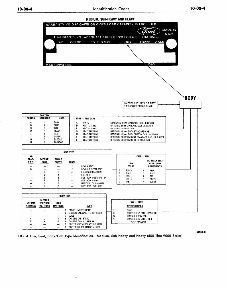
MEDIUM, SUB-HEAVY AND HEAVY
BODYON COWL/BUS UNITS THE FIRST
TWO SPACES REMAIN BLANK
CUSTOM
ABCDEFGH
CAB TRIM
STANDARD
12345678
CABS
GRAY
BLUE
TANBLACK
REDGREEN
SADDLE
TOBACCO
F500 — F600 CABS
VINYL
KNIT & VINYL
KNIT & VINYL
LEATHER VINYL
LEATHER VINYL
LEATHER VINYL
LEATHER VINYL
STANDARD TRIM STANDARD CAB L/B BENCH
OPTIONAL TRIM STANDARD CAB L/B BENCH
OPTIONAL CUSTOM CAB
OPTIONAL HEAVY DUTY STANDARD CAB
OPTIONAL HEAVY DUTY CUSTOM CAB L/B BENCH
OPTIONAL BOSTROM SEAT STANDARD CAB L/B BUCKET
OPTIONAL BOSTROM SEAT CUSTOM CAB
HDBLACK
VINYL
AB———_
—
W/COMP.
PASS.
cDEFGH
SINGLE
DRIVER
345678
SEAT TYPE
BENCH
12_—
—
BENCH SEAT
BENCH CUSTOM SEAT
L-S (UNISON ACTION)
L-S #675
BOSTROM WESTCOASTER
BOSTROM T-BAR
NATIONAL CUSH-N-AIREBOSTROM LEVELAIRE
F500 — F600
TRIM
COLOR
ABDGU
BLACK
BLUE
REDGREEN
TAN
HD BLACK SEAT
WITH COLOR
COMPONENTS
RED
BLUE
TAN
GREEN
BLACK
W/FOAMMATTRESS
SLEEPERW/SPRINGMATTRESS
J
K
BODY TYPE
LESSMATTRESS
— 0a
— 7
Y 8
Q H
— 6
— 7
BODY
PARCEL, MOTOR HOME
CHASSIS CAB/W/BUTTERFLY HOOD
COWL
CHASSIS CAB, STEEL
CHASSIS CAB, ALUMINUM
FIRE TRUCK/EMERGENCY CC STEEL
FIRE TRUCK W/BUTTERFLY HOOD
F500 — F600
SPECIFICATIONS
COWL
CHASSIS CAB STEEL REGULAR
CHASSIS CREW CAB
CHASSIS CAB STEEL, FIRE
TRUCK REGULAR
W1343-B
FIG. 4 Trim, Seat, Body/Cab Type Identification—Medium, Sub Heavy and Heavy (500 Thru 9000 Series)
10-00-5 Identification Codes 10-00-5
ENGINEERINGCODE
AA
GA
DADBDDDUDG
EAEBEDEUEG
HA
COMPONENTCOLOR
W/BLACK
\ W/BLACK\ W/BLUE
) W/RED/ W/TAN
/ W/GREEN
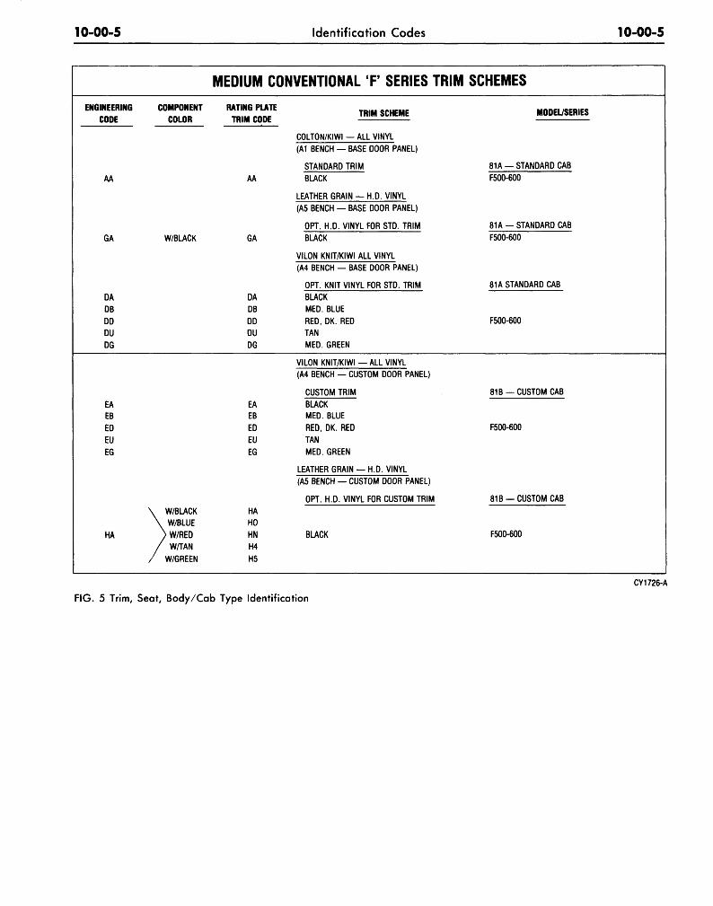
MEDIUM CONVENTIONAL F SERIES TRIM
RATING PLATETRIM CODE
AA
GA
DADBDDDUDG
EAEBEDEUEG
HAHOHNH4H5
TRIM SCHEME
COLTON/KIWI — ALL VINYL(A1 BENCH — BASE DOOR PANEL)
STANDARD TRIMBLACK
LEATHER GRAIN - H.D. VINYL(A5 BENCH - BASE DOOR PANEL)
OPT. H.D. VINYL FOR STD. TRIMBLACK
VILON KNIT/KIWI ALL VINYL(A4 BENCH — BASE DOOR PANEL)
OPT. KNIT VINYL FOR STD. TRIMBLACKMED. BLUERED, DK. REDTANMED. GREEN
VILON KNIT/KIWI — ALL VINYL(A4 BENCH — CUSTOM DOOR PANEL)
CUSTOM TRIMBLACKMED. BLUERED, DK. REDTANMED. GREEN
LEATHER GRAIN — H.D. VINYL(A5 BENCH — CUSTOM DOOR PANEL)
OPT. H.D. VINYL FOR CUSTOM TRIM
BUCK
SCHEMES
MODEL/SERIES
81A — STANDARD CABF500-600
81 A — STANDARD CABF500-600
81A STANDARD CAB
F500-600
81B — CUSTOM CAB
F500-600
81B — CUSTOM CAB
F500-600
CY1726-A
FIG. 5 Trim, Seat, Body/Cab Type Identification
10-00-6 Identification Codes 10-00-6
ENGINEERINGCODE
AA
GA
DADBDDDUDG
EAEDEUEG
HA
KA
LA
MED
COMPONENTCOLOR
\ W/BLACK\ W/BLUE
) W/RED/W/GINGER
/ W/GREEN
DRIVER
46
D6
. HEAVY
RATING PLATETRIM CODE
41
4A
4222523262
D1E1C1F1
DABAEACAFA
DRIVERW/PASSENGER
4F
DF
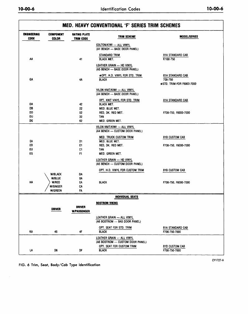
CONVENTIONAL T SERIES TRIM
TRIM SCHEME
COLTON/KIWI — ALL VINYL(A1 BENCH — BASE DOOR PANEL)
STANDARD TRIMBUCK MET.
LEATHER GRAIN — HD VINYL(A5 BENCH — BASE DOOR PANEL)
•OPT. H.D. VINYL FOR STD. TRIMBLACK
VILON K N I T / K I W I - A L L VINYL(A4 BENCH — BASE DOOR PANEL)
OPT. KNIT VINYL FOR STD. TRIMBUCK MET.MED. BLUE MET.RED, DK. RED MET.TANMED. GREEN MET.
VILON KNIT/KIWI — ALL VINYL(A4 BENCH — CUSTOM DOOR PANEL)
MED. TRUCK CUSTOM TRIMMED. BLUE MET.RED, DK. RED MET.TANMED. GREEN MET.
LEATHER GRAIN — HD VINYL(A5 BENCH — CUSTOM DOOR PANEL)
OPT. H.D. VINYL FOR CUSTOM TRIM
BUCK
INDIVIDUAL SEATS
BOSTROM VIKING
LEATHER GRAIN - ALL VINYL(A6 BOSTROM — BAS DOOR PANEL)
OPT. SEAT FOR STD. TRIMBUCK
LEATHER GRAIN — ALL VINYL(A6 BOSTROM — CUSTOM DOOR PANEL)
OPT. SEAT FOR CUSTOM TRIMBUCK
SCHEMES
MODEL/SERIES
81A STANDARD CABF/100-750
81A STANDARD CAB700-750
•STD. TRIM FOR F6000-7000
81A STANDARD CAB
F700-750, F6000-7000
81B CUSTOM CAB
F700-750, F6000-7000
81B CUSTOM CAB
F700-750, F6000-7000
81A STANDARD CABF700-750-7000
81D CUSTOM CABF700-750-7000
FIG. 6 Trim, Seat, Body/Cab Type IdentificationCY1727-A
10-00-7 Identification Codes 10-00-7
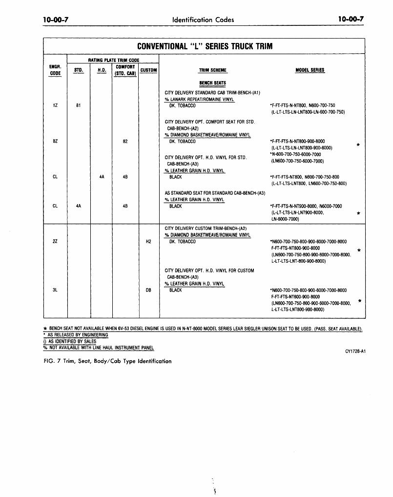
CONVENTIONAL "L" SERIES TRUCK TRIM
ENGR.CODE
1Z
BZ
CL
CL
RATING PLATE TRIM CODE
STD.
81
4A
H.D.
4A
COMFORT(STD. CAB)
82
4B
4B
CUSTOM TRIM SCHEME
BENCH SEATS
CITY DELIVERY STANDARD CAB TRIM-BENCH-(AI)% LANARK REPEAT/ROMAINE VINYL
DK. TOBACCO
CITY DELIVERY OPT. COMFORT SEAT FOR STD.CAB-BENCH-(A2)
% DIAMOND BASKETWEAVE/ROMAINE VINYLDK. TOBACCO
CITY DELIVERY OPT. H.D. VINYL FOR STD.CAB-BENCH-(A3)
% LEATHER GRAIN H.D. VINYLBLACK
AS STANDARD SEAT FOR STANDARD CAB-BENCH-(A3)% LEATHER GRAIN H.D. VINYL
BLACK
MODEL SERIES
•F-FT-FTS-N-NT800, N600-700-750(L-LT-LTS-LN-LNT800-LN-600-700-750)
•F-FT-FTS-N-NT800-900-8000(L-LT-LTS-LN-LNT800-900-8000)
•N-600-700-750-6000-7000(LN600-700-750-6000-7000)
•F-FT-FTS-NT800, N600-700-750-800(L-LT-LTS-LNT800, LN600-700-750-800)
• F-FT-FTS-N-NT900-8000, N6000-7000(L-LT-LTS-LN-LNT900-8000, •LN-6000-7000)
2Z
3L
H2
DB
CITY DELIVERY CUSTOM TRIM-BENCH-(A2)% DIAMOND BASKETWEAVE/ROMAINE VINYL
DK. TOBACCO
CITY DELIVERY OPT. H.D. VINYL FOR CUSTOMCAB-BENCH-(A3)
% LEATHER GRAIN H.D. VINYLBLACK
•N600-700-750-800-900-6000-7000-8000F-FT-FTS-NT800-900-8000(LN600-700-750-800-900-6000-7000-8000,L-LT-LTS-LNT-800-900-8000)
•N600-700-750-800-900-6000-7000-8000F-FT-FTS-NT600-900-8000(LN600-700-750-800-900-6000-7000-8000,L-LT-LTS-LNT800-900-8000)
• BENCH SEAT NOT AVAILABLE WHEN 6V-53 DIESEL ENGINE IS USED IN N-NT-8000 MODEL SERIES LEAR SIEGLER UNISON SEAT TO BE USED. (PASS. SEAT AVAILABLE).* AS RELEASED BY ENGINEERING() AS IDENTIFIED BY SALES% NOT AVAILABLE WITH LINE HAUL INSTRUMENT PANEL
FIG. 7 Trim, Seat, Body/Cab Type Identification
10-00-8 Identification Codes 10-00-8
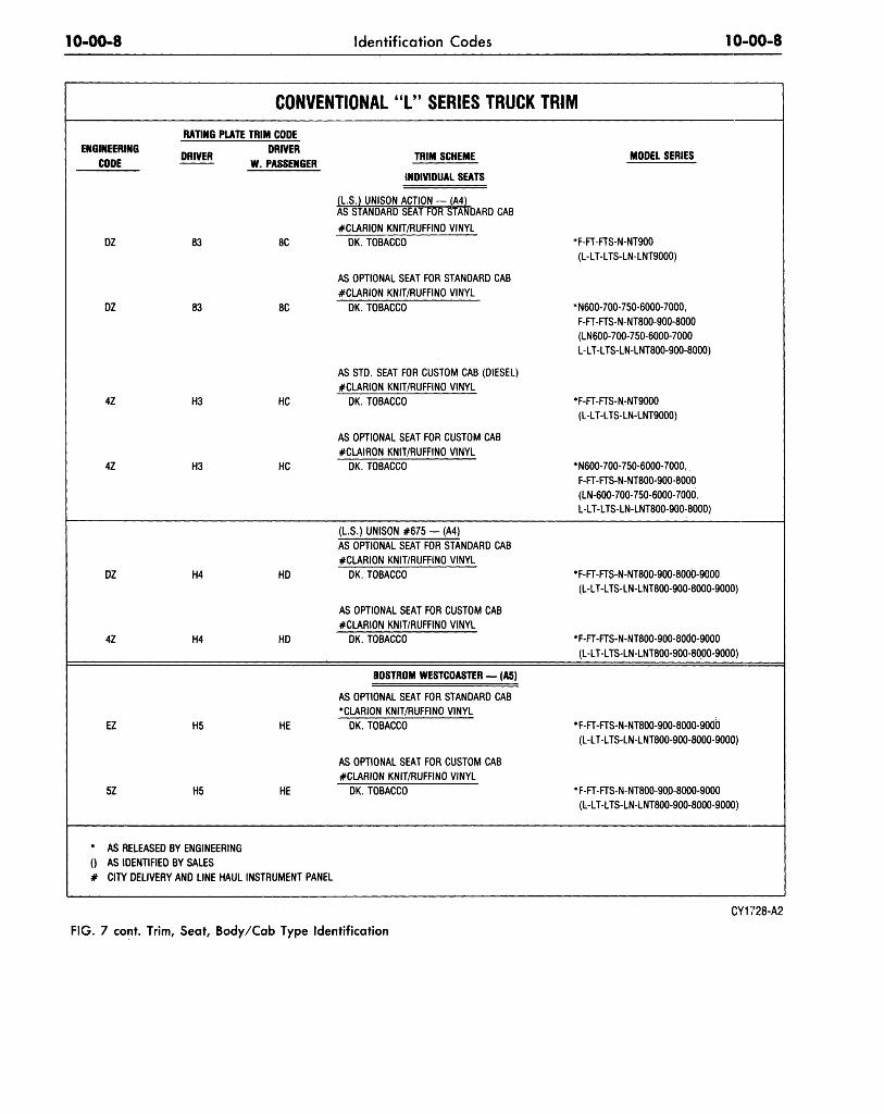
ENGINEERINGCODE
DZ
DZ
4Z
4Z
DZ
4Z
EZ
5Z
CONVENTIONAL "L" SERIES TRUCKRATING PLATE TRIM CODE
DRIVER
83
83
H3
H3
H4
H4
H5
H5
• AS RELEASED BY ENGINEERING() AS IDENTIFIED BY SALES# CITY DELIVERY AND LINE HAUL
DRIVERW. PASSENGER
8C
8C
HC
HC
HD
HD
HE
HE
TRIM SCHEME
INDIVIDUAL SEATS
(L.S.) UNISON ACTION — (A4)AS STANDARD SEAT FOR STANDARD CAB#CLARION KNIT/RUFFINO VINYL
DK. TOBACCO
AS OPTIONAL SEAT FOR STANDARD CAB#CLARION KNIT/RUFFINO VINYL
DK. TOBACCO
AS STD. SEAT FOR CUSTOM CAB (DIESEL)#CLARION KNIT/RUFFINO VINYL
DK. TOBACCO
AS OPTIONAL SEAT FOR CUSTOM CAB#CLAIRON KNIT/RUFFINO VINYL
DK. TOBACCO
(L.S. UNISON #675 - (A4)AS OPTIONAL SEAT FOR STANDARD CAB#CLARION KNIT/RUFFINO VINYL
DK. TOBACCO
AS OPTIONAL SEAT FOR CUSTOM CAB#CLARION KNIT/RUFFINO VINYL
DK. TOBACCO
BOSTROM WESTCOASTER — (A5)
AS OPTIONAL SEAT FOR STANDARD CAB•CLARION KNIT/RUFFINO VINYL
DK. TOBACCO
AS OPTIONAL SEAT FOR CUSTOM CAB#CLARION KNIT/RUFFINO VINYL
DK. TOBACCO
INSTRUMENT PANEL
TRIM
MODEL SERIES
•F-FT-FTS-N-NT900(L-LT-LTS-LN-LNT9000)
•N600-700-750-6000-7000,F-FT-FTS-N-NT800-900-8000(LN600-700-750-6000-7000L-LT-LTS-LN-LNT800-900-8000)
•F-FT-FTS-N-NT9000(L-LT-LTS-LN-LNT9000)
•N600-700-750-6000-7000,F-FT-FTS-N-NT800-900-8000(LN-600-700-750-6000-7000,L-LT-LTS-LN-LNT800-900-8000)
•F-FT-FTS-N-NT800-900-8000-9000.(L-LT-LTS-LN-LNT800-900-8000-9000)
•F-FT-FTS-N-NT800-900-8000-9000(L-LT-LTS-LN-LNT800-900-8000-9000)
•F-FT-FTS-N-NT800-900-8000-90dd(L-LT-LTS-LN-LNT800-900-8000-9000)
•F-FT-FTS-N-NT800-900-8000-9000(L-LT-LTS-LN-LNT800-900-8000-9000)
FIG. 7 cont. Trim, Seat, Body/Cab Type Identification
CY1728-A2
10-00-9 Identification Codes 10-00-9
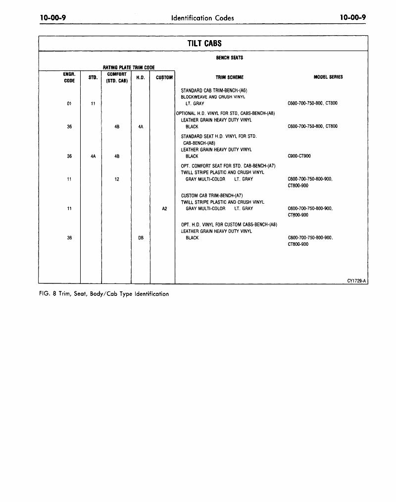
TILT CABS
EN6R.
CODE
01
36
36
11
11
36
RATING PLATE TRIM CODE
STD.
11
4A
COMFORT
(STD. CAB)
4B
4B
12
H.D.
4A
DB
CUSTOM
A2
BENCH SEATS
TRIM SCHEME MODEL SERIES
STANDARD CAB TRIM-BENCH-(A6)
BLOCKWEAVE AND CRUSH VINYL
LT. GRAY C600-700-750-800, CT800
OPTIONAL H.D. VINYL FOR STD, CABS-BENCH-(A8)
LEATHER GRAIN HEAVY DUTY VINYL
BLACK C600-700-750-800, CT800
STANDARD SEAT H.D. VINYL FOR STD.
CAB-BENCH-(A8)
LEATHER GRAIN HEAVY DUTY VINYL
BLACK C900-CT900
OPT. COMFORT SEAT FOR STD. CAB-BENCH-(A7)
TWILL STRIPE PLASTIC AND CRUSH VINYL
GRAY MULTI-COLOR LT. GRAY C600-700-750-800-900,
CT800-900
CUSTOM CAB TRIM-BENCH-(A7)
TWILL STRIPE PLASTIC AND CRUSH VINYL
GRAY MULTI-COLOR LT. GRAY C600-700-750-800-900,
CT800-900
OPT. H.D. VINYL FOR CUSTOM CABS-BENCH-(A8)
LEATHER GRAIN HEAVY DUTY VINYL
BLACK C600-700-750-800-900,
CT800-900
CY1729-A
FIG. 8 Trim, Seat, Body/Cab Type Identification
10-00-10 Identification Codes 10-00-10
ENGINEERINGCODE
26
26
26
26
7F
8F
7F
8F
77F
78F
7F
8F
RATING
DRIVER
43
43
D3
D3
G4
G4
G5
G5
' G7
G7
G8
G8
PLATE TRIM CODEDRIVER
W/PASSENGER
4C
4C
DC
DC
GD
GD
GE
GE
GG
GG
GH
GH
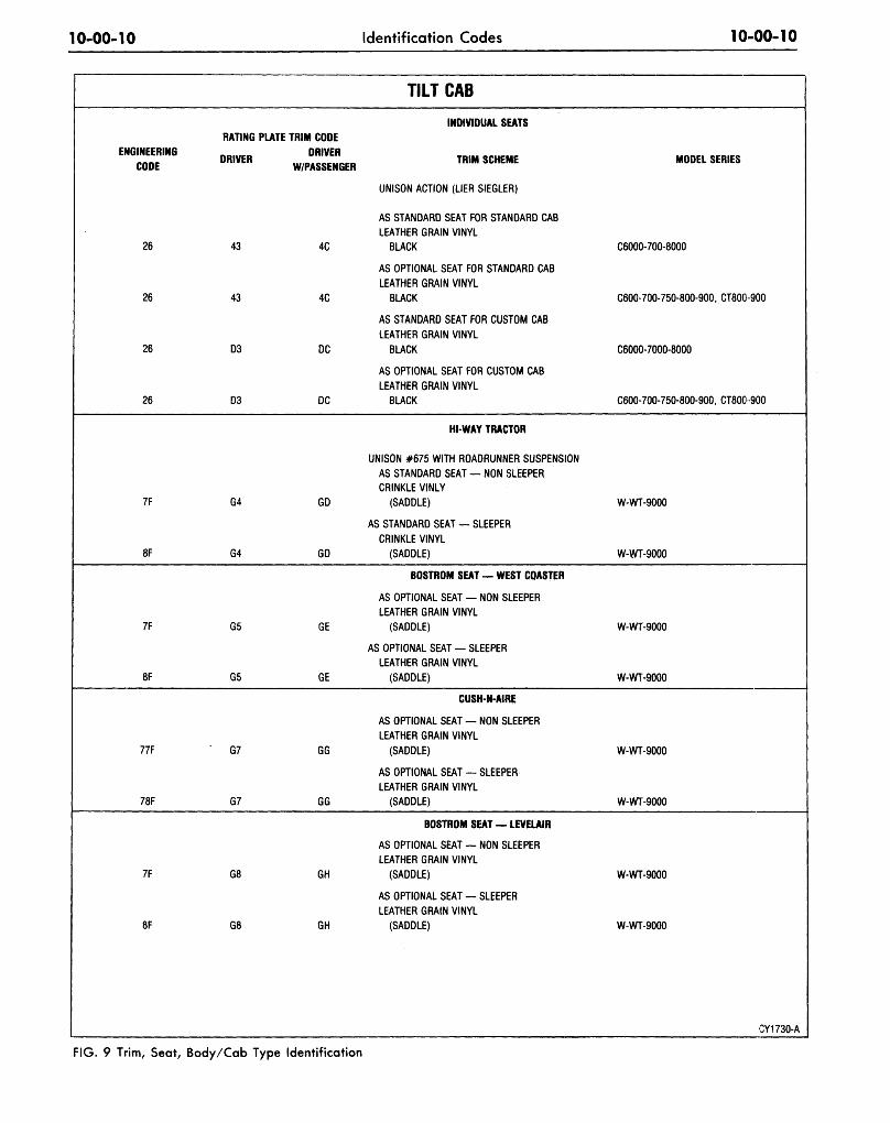
TILT CAB
INDIVIDUAL SEATS
TRIM SCHEME
UNISON ACTION (LIER SIEGLER)
AS STANDARD SEAT FOR STANDARD CABLEATHER GRAIN VINYL
BLACK
AS OPTIONAL SEAT FOR STANDARD CABLEATHER GRAIN VINYL
BLACK
AS STANDARD SEAT FOR CUSTOM CABLEATHER GRAIN VINYL
BLACK
AS OPTIONAL SEAT FOR CUSTOM CABLEATHER GRAIN VINYL
BUCK
HI-WAY TRACTOR
UNISON #675 WITH ROADRUNNER SUSPENSIONAS STANDARD SEAT — NON SLEEPERCRINKLE VINLY
(SADDLE)
AS STANDARD SEAT — SLEEPERCRINKLE VINYL
(SADDLE)
BOSTROM SEAT — WEST COASTER
AS OPTJONAL SEAT — NON SLEEPERLEATHER GRAIN VINYL
(SADDLE)
AS OPTIONAL SEAT — SLEEPERLEATHER GRAIN VINYL
(SADDLE)
CUSH-N-AIRE
AS OPTIONAL SEAT — NON SLEEPERLEATHER GRAIN VINYL
(SADDLE)
AS OPTIONAL SEAT — SLEEPERLEATHER GRAIN VINYL
(SADDLE)
BOSTROM SEAT-LEVELAIR
AS OPTIONAL SEAT — NON SLEEPERLEATHER GRAIN VINYL
(SADDLE)
AS OPTIONAL SEAT — SLEEPERLEATHER GRAIN VINYL
(SADDLE)
MODEL SERIES
C6000-700-8000
C600-700-750-800-900, CT800-900
C6000-7000-8000
C600-700-750-800-900, CT800 900
W-WT-9000
W-WT-9000
W-WT-9000
W-WT-9000
W-WT-9000
W-WT-9000
W-WT-9000
W-WT-9000
CY1730-A
FIG. 9 Trim, Seat, Body/Cab Type Identification
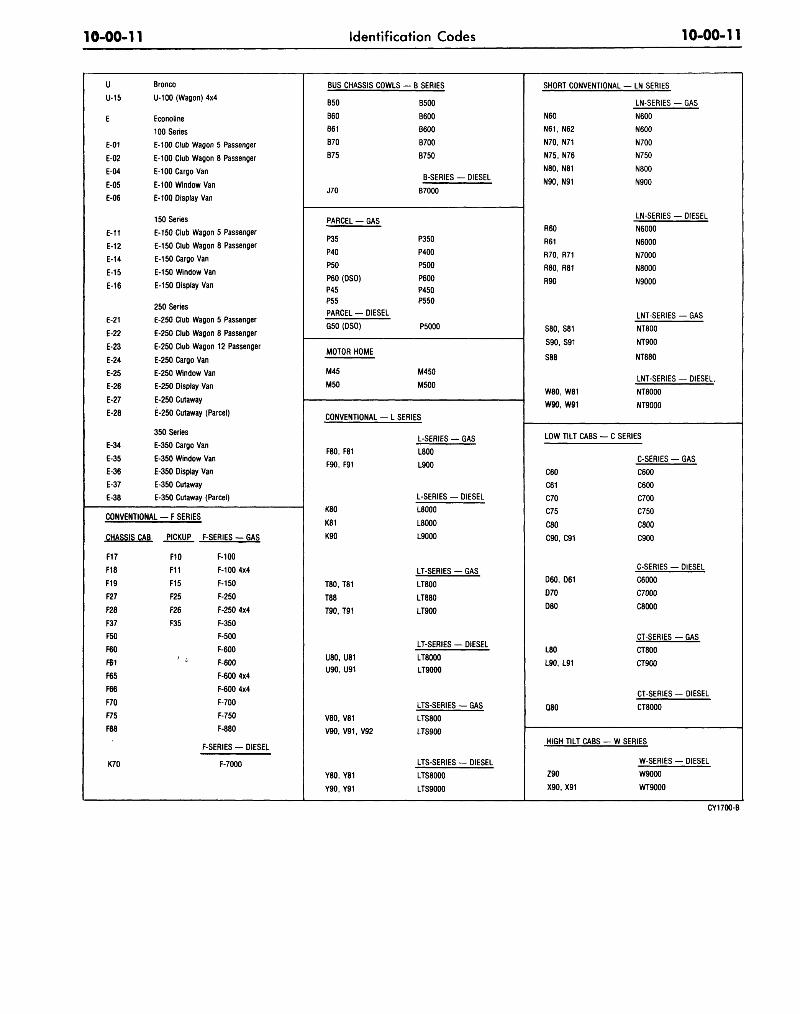
10-00-11 Identification Codes 10-00-11
uU-15
E
E-01
E-02
E-04
E-05
E-06
E-11
E-12
E-14
E-15
E-16
E-21
E-22
E-23
E-24
E-25
E-26
E-27
E-28
E-34
E-35
E-36
E-37
E-38
Bronco
U-100 (Wagon) 4x4
Econoline
100 Series
E-100 Club Wagon 5 Passenger
E-100 Club Wagon 8 Passenger
E-100 Cargo Van
E-100 Window Van
E-10Q Display Van
150 Series
E-150 Club Wagon 5 Passenger
E-150 Club Wagon 8 Passenger
E-150 Cargo Van
E-150 Window Van
E-150 Display Van
250 Series
E-250 Club Wagon 5 Passenger
E-250 Club Wagon 8 Passenger
E-250 Club Wagon 12 Passenger
E-250 Cargo Van
E-250 Window Van
E-250 Display Van
E-250 Cutaway
E-250 Cutaway (Parcel)
350 Series
E-350 Cargo Van
E-350 Window Van
E-350 Display Van
E-350 Cutaway
E-350 Cutaway (Parcel)
CONVENTIONAL — F SERIES
CHASSIS CAB PICKUP F-SERIES — GAS
F17
F18
F19
F27
F28
F37
F50
F60
F61
F65
F66
F70
F75
F88
K70
F10 F-100
F11 F-100 4x4
F15 F-150
F25 F-250
F26 F-250 4x4
F35 F-350
F-500
F-600
' * F-600
F-600 4x4
F-600 4x4
F-700
F-750
F-880
F-SERIES — DIESEL
F-7000
BUS CHASSIS COWLS
B50
B60
B61
B70
B75
J70
PARCEL GAS
P35
P40
P50
P60 (DSO)
P45
P55
PARCEL — DIESEL
G50(DSO)
MOTOR HOME
M45
M50
> — B SERIES
B500
B600
B600
B700
B750
B-SERIES — DIESEL
B7000
P350
P400
P500
P600
P450
P550
P5000
M450
M500
CONVENTIONAL — L SERIES
F80, F81
F90, F91
K80
K81
K90
T80, T81
T88
T90, T91
U80, U81
U90, U91
V80, V81
V90.V91.V92
Y80. Y81
Y90, Y91
L-SERIES — GAS
L800
L900
L-SERIES — DIESEL
L8000
L8000
L9000
LT-SERIES GAS
LT800
LT880
LT900
LT-SERIES — DIESEL
LT8000
LT9000
LTS-SERIES — GAS
LTS800
LTS900
LTS-SERIES DIESEL
LTS8000
LTS9000
SHORT CONVENTIONAL — LN SERIES
LN-SERIES — GAS
N60
N61, N62
N70, N71
N75, N76
N80, N81
N90, N91
R60
R61
R70, R71
R80, R81
R90
S80, S81
S90, S91
S88
W80, W81
W90, W91
LOW TILT CABS —
C60
C61
C70
C75
C80
C90, C91
D60, D61
D70
D80
L80
L90, L91
Q80
HIGH TILT CABS -
Z90
X90. X91
N600
N600
N700
N750
N800
N900
LN-SERIES — DIESEL
N6000
N6000
N7000
N8000
N9000
LNT-SERIES — GAS
NT800
NT900
NT880
LNT-SERIES — DIESEL.
NT8000
NT9000
C SERIES
C-SERIES — GAS
C600
C600
C700
C750
C800
C900
C-SERIES — DIESEL
C6000
C7000
C8000
CT-SERIES — GAS
CT800
CT900
CT-SERIES — DIESEL
CT8000
- W SERIES
W-SERIES — DIESEL
W9000
WT9000
CY1700-B
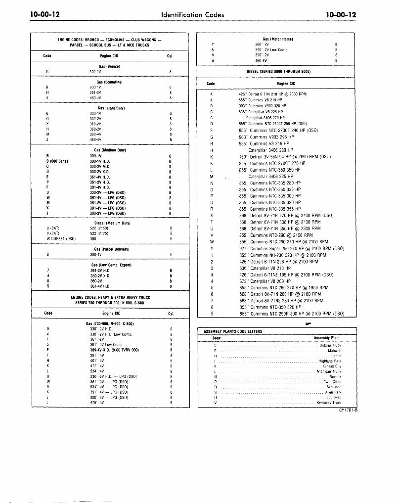
10-00-12 Identification Codes 10-00-12
ENGINE CODES:
PARCEL
Code
G
B
H
A
B
G
Y
H
M
J
B
B (600 Series)
C
D
E
P
F
UW
M
X
J
U (CAT)
V (CAT)
W DORSET(DSO)
B
7
4
8
5
ENGINE
BRONCO — ECONOLINE — CLUB WAGONS —
— SCHOOL BUS — LT & MED TRUCKS
Engine CID
Gas (Bronco)
302-2V
Gas (Econoline)
300-1V
351-2V
460-4V
Gas (Light Duty)
300-1V
302-2V
360-2V
390-2V
390-4V
460-4V
Gas (Medium Duty)
300-1V
300-1V H.D.
330-2V M.D.
330-2V X.D.
361-4V H.D.
361-2V H.D.
391-4V H.D.
330-2V — LPG (DSO)
361-4V —LPG(DSO)
361-2V —LPG(DSO)
391 -4V — LPG (DSO)
300-2V — LPG (DSO)
Diesel (Medium Duty)
522 (V150)
522 (V175)
380
Gas (Parcel Delivery)
300-1V
Gas (Low Comp. Export)
361-2V H.D.
330-2V X.D.
360-2V
361-4VH.D.
CODES: HEAVY & EXTRA HEAVY TRUCK
SERIES 700 THROUGH 900, N-600, C-600
Code
D
4
E
5
F
F
H
K
L
U
W
9
X
J
J
Engine CID
Gas (700-900, N-600, C-600)
330"-2VH.D.
330"-2V H.D. Low Comp.
361 "-2V
361 "-2V Low Comp.
389-4V X.D. (9.00 TVRV 900)
391 "-4V
401 "-4V
477' -4V
534"-4V
330"-2VH.D. - L P G (DSO)
361"-2V —LPG (DSO)
534"-4V — LPG (DSO)
391"-4V — LPG (DSO)
300 "-2V — LPG (DSO)
475"-4V
Cyl.
8
6
8
8
6
8
8
8
8
8
6
6
8
8
8
8
8
8
8
8
8
6
8
8
6
6
8
8
8
8
Cyl.
8
8
8
8
8
8
8
8
8
8
8
8
8
6
8
Y
8
H
A
Code
A
A
B
cC
D
F
GHHK
KLMN0P
QR
STUVWY1
234456789
Gas (Motor Home)
360"-2V 8
360 "-2V Low Comp. 8
390"-2V 8
460-4V 8
DIESEL (SERIES 5000 THROUGH 9000)
Engine CID
426" Detroit 6-71N 218 HP @ 2300 RPM
555" Cummins V8 210 HP
903" Cummins V903 320 HP
636" Caterpillar V8 225 HP
Caterpillar 3406 ?70 HP
855" Cummins NTC-270CT 255 HP (DSO)
855" Cummins NTC-270CT 240 HP (DSO)
903" Cummins V903 295 HP
555" Cummins V8 216 HP
Caterpillar 3406 280 HP
159" Detroit 3V-53N 94 HP @ 2800 RPM (DSO)
855" Cummins NTC-270CT 270 HP
855 ' Cummins NTC-350 350 HP
Caterpillar 3406 325 HP
855" Cummins NTC-335 280 HP
855" Cummins NTC-350 335 HP
855" Cummins NTC-335 300 HP
855" Cummins NTC-335 320 HP
855" Cummins NTC-335 355 HP
568" Detroit 8V-71N 270 HP @ 2100 RPM (DSO)
568" Detroit 8V-71N 308 HP @ 2100 RPM
568" Detroit 8V-71N 350 HP @ 2300 RPM
855" Cummins NTC-290 @ 2100 RPM
855" Cummins NTC-290 270 HP @ 2100 RPM
927" Cummins Super 250 270 HP @ 2100 RPM (DSO)
855" Cummins NH-230 220 HP @ 2100 RPM
426" Detroit 6-71N 228 HP @ 2100 RPM
636" Caterpillar V8 210 HP
426" Detroit 6-71NE 195 HP @ 2100 RPM (DSO)
573" Caterpillar V8 200 HP
855" Cummins NTC 290 270 HP @ 1950 RPM
568" Detroit 8V-71N 280 HP @ 2100 RPM
568" Detroit 8V-71NE 260 HP @ 2100 RPM
855" Cummins NTC-350 320 HP
855" Cummins NTC-290R 300 HP @ 2100 RPM (DSO)
ASSEMBLY PLANTS CODE LETTERS
Code
C
E
H
I
K
L
N
P
R
S
U :
V
Assembly Plant
Ontario Tru :k
Mahwah
Lorain
Highland P a *
Kansas City
Michigan Truck
Norfolk
Twin Cities
San Jo:;e
Allen Pa-k
LouisviHe
Kentucky Truck
CY1701-B
10-00-13 Identification Codes 10-00-13
•Job # 11976
•Job # 11Q7S• •I/O
* AugustSeptember
OctoberNovemberDecember
•JanuaryFebruary
MarchApril
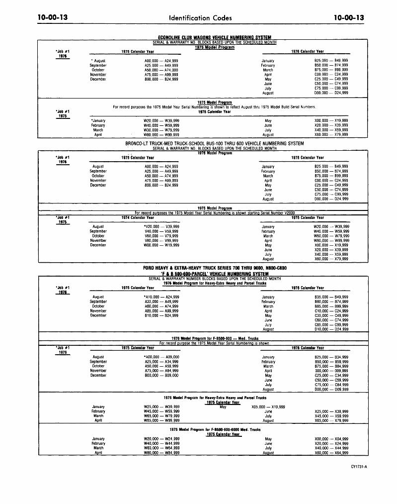
ECONOLINE CL JB WAGONS VEHICLE NUMBERING SYSTEM
1975 Calendar Year
AOO.OOO — A24.999A25.000 — A49.999A50.000 — A74.000A75.000 — A99.999B00.000 — B24.999
1976 Mode l Program1976 Calendar Year
JanuaryFebruary
MarchAprilMayJuneJuly
August
B25.000 — B49.999B50.000 — B74.999B75.000 - B99.999C00.000 — C24.999C25.000 — C49.999C50.000 — C74.999C75.000 — C99.999D00.000 — D24.999
1975 Model ProaramFor record purposes the 1975 Model Year Serial Numbering is shown to reflect August thru 1975 Model Build Serial Numbers.
W20.000 — W39.999W40.000 — W59.999W30.000 — W79.999W80.000 — W99.999
1975 Calendar Year
MayJuneJuly
August
X00.000 — X19.999X20.00O—X39.999X40.000 — X59.999X60.000 — X79.999
•Job # 1
•Job # 1
J975_
AugustSeptember
OctoberNovemberDecember
AugustSeptember
OctoberNovemberDecember
BRONCO-LT TRUCK-MED TRUCK-SCHOOL BUS-100 THRU 600 VEHICLE NUMBERINGSERIAL & WARRANTY NO. BLOCKS BASED UPON THE SCHEDULED MONTH
1975 Calendar Year
AOO.OOO — A24.999A25.000 — A49.999A50.000 — A74.999A75.000 — A99.999B00.000 — B24.999
1976 Model Program
JanuaryFebruaryMarchAprilMayJuneJuly
August
1975 Model Program
SYSTEM
1976 Calendar Year
B25.000 — B49.999B50.000 — B74.999B75.000 — B99.999COO, 000 — C24.999C25.000 — C49.999C50.000 — C74.999C75.000 — C99.999D00.000 — D24.999
For record purposes the 1975 Model Year Serial Numbering, is shown starting Serial Number V20001974 Calendar Year
•V20.000 — V39.999V40.000 — V59.999V60.000 — V79.999V80.000 — V99.999
W00.000 — W19,999
JanuaryFebruary
MarchAprilMayJuneJuly
August
1975 Calendar Year
W20.000 — W39.999W40.000 — W59.999W60.000 — W79.999W80.000 — W99.999X00.000 — X19,999X20.000 — X39.999X40.000 — X59.999X60.000 — X79.999
•Job # 1
1876
•Job # 11976
AugustSeptember
OctoberNovemberDecember
AugustSeptember
OctoberNovemberDecember
JanuaryFebruary
MarchApril
JanuaryFebruary
MarchApril
FORD HEAVY & EXTRA-HEAVY TRUCK SERIES 700 THRU 9000, N600-C600' F A B 500-600-PARCEL' VEHICLE NUMBERING SYSTEM
SERIAL & WARRANTY NUMBER BLOCKS BASED UPON THE SCHEDULED MONTH1976 Model Program for Heavy-Extra Heavy and Parcel Trucks
1975 Calendar Year
•A10,000 — A24.999A35.000 — A49.999A60.000 — A74.999A85.000 — A99.999B10.000 — B24.999
1976 Model Program for F-B500-600 — Med.
JanuaryFebruary
MarchAprilMayJuneJuly
August
TrucksFor record purpose the 1975 Model Year Serial Numbering is shown.
1975 Calendar Year
•AOO.OOO — A09.000A25.000 — A34.999A50.000 — A59.999A75.000 — A84.999B00.000 — B09.000
JanuaryFebruaryMarchAprilMayJuneJuly
August
1975 Model Program for Heavy-Extra Heavy and Parcel Trucks
W25.000 — W39.999 MayW45.000 — W59.999W65.000 — W79.999W85.000 — W99.999
1975 Calendar YearW20.000 — W24.999W40.000 — W44.999W60.000 — W64.999W80.000 — W84.999
X05.000 —X19.999JuneJuly
August
. Trucks
MayJuneJuly
August
1976 Calendar Year
B35.000 — B49.999B60.000 — B74.999B85.000 — B99.999C10.000 — C24.999C35.000 — C49.999C60.000 — C74.999C85.000 — C99.999D10.000 — D24.999
1976 Calendar Year
B25.000 — B34.999B50.000 — B59.999B75.000 — B84.999000,000 — 009.999C25.000 — C34.999C50.000 — C59.999C75.000 — C84.999D00.000 — D09.999
X25.000 — X39.999X45.000 — X59.999X65.000 — X79.999
X00.000 — X04.999X20.000 — X24.999X40.000 —X44.999X60.000 — X64.999
CY1731-A
10-00-14 Identification Codes 10-00-14
i !
Code
T
P
N
8
V
U
X
3
Z
G
M
9
W
4'
14
A
KTJ
P
S
1
0
8L
U63X
R2
YZ4G
CM7
D
E ^
H
9
W4
F
21
G —
Paint Quality (ALT)
ESB-
Color
Black
Brt. Red
RedRangoon Red
Lt. Blue
Brt. Dk. Blue Met.
Med. Blue Met.
Brt. Med. Blue
Dk. Green
Dk. Yellow Green Met.
Dk. Green
Med. Green Gold
Dk. Jade Met.
Lt. Green
Dk. Brown (for Tutone)
TanTan
Med. Ginger Met.
Tangerine
Med. Orange Met.
Yellow Orange
Copper Met.
Gold
Chrome Yellow •
Special White (RPO)
White
White
)} White (KTP Only)
)
NOTE: Kentucky Truck
Red M6J102B
Prime Gray M6J103B
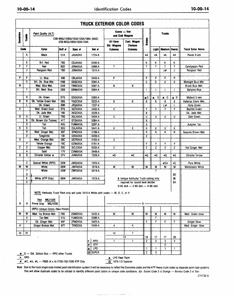
TRUCK EXTERIOR COLOR CODES
M50J1200A/103A/105A/106A (NAD)ESB-M32J100A/102A/104A
Surf #
C1A
78D80D79D
40BH9BG4BG8B
D7G
36G89R97G16K79G41T40U52U90F13E20C18C
25C17V07V
32W26W43W
26W
Plant on
(RPO) Unique Colors (Non-Polish)
Med. Ivy Bronze Met.
Tan Met.
Dk. Ginger Met.
Ginger Bronze Met.
•-
Std. School Bus — RPO <
F9G41U94F87F
Spec#
JASAXXA
CDJAXXA
JDMAXXA
JDNAXXA
CBLAXXA
SBQCXXA
TBMCXXA
QBMAXXA
QGQAXXA
YGQCXXA
JRQAXXA
AGTAXXA
AKQCXXA
AGLAXXA
QTQAXXA
YUMAXXA
CULAXXA
SFNCXXA
CEKAXXA
UCPAXXA
UCNAXXA
SCLCXXA
CVMAXXA
JVMAXXA
JWGAXXA
JWFAXXA
ZWFAXXA
JWFAXXA
y will code 161 £
ZGMDXXA
YUMDXXA
ZFMDXXA
TFNDXXA
)ther Trucks
Ref#
1724-A
5440-A
2008-A
1515-A
5443-A
5094-A
5087-A
5004-A
5005-A
5223-A
1237-A
5402-A
5328-A
5404-A
5064-A
5297-A
5441-A
5186-A
5459-A
5183-A
5181-A
5035-A
5448-A
1526-A
1525-A
1619-A
5418-A
1619-A
)-A White with c
5435-A
5298-A
5425-A
5436-A
•
#A]
RPOKTPLPO
EXPLR
Econo — Van
and Club Wagons
All Vans
Std. Wagons
Cutaway
T
P
N
8
V
U
X
3
Z
•G
M
Cust. Wagon
Chateau
Cutaway
N
8
X
•G
M
!
•A
KT
P
S
1
AO8
YBU63XR
2
Y
Z
•G
M
Trucks
Light
•A
KT
PS
I
A 0
8
Y
U
XR
Y
Z
•G
M7
$ Unique Kentucky Truck coding only
required for sound level decibel
D-83 dbA — E-86 dbA
odes — M, D, E, or H
9
W
4
14
W
4
7
141 1
— H-88 dbA
W
F
192
1
2
W7F
172
1
3
•i.ji
M 8(11 Urn
•A
KT
J#
P
S
I
[A 0
8L#Y
U
XR
Y
Z
•G
# O
M
W
F
17
321
Heavy
•A
KTJ
PS
I
A 0
8LY
U
XR
YZ
•G
•CM
$D$E$H
W
F
203
1
Truck Sales Name
Raven 6 ack
Candyapply Red
Rangoon Red
Midnight Bite Met.
Brook Blue Met.
Bahama Blue
Mallard G'een
Hatteras Green Met.
Holly Green
|_ Baytree Green
Dk. Jade Met.
Glen Green
Autumn Tan
Sequoia Brown Met.
Hot Ginger Met.
Chrome Yellow
Pure White
Wimbledon White
Med. Green Glow
Ginger Glow
Med. Ginger Glow
• RPO A LPO Fleet Paint
# #C, # J , # L — F600 (4 x 4) F700-750-7000 KTP Only @ 1975-1/2 Explorer
Note: Due to the truck single code limited paint identification system it will be necessary to reflect the Econoline codes and the KTP Heavy truck codes as separate paint code systems.
This will allow duplicate codes to be utilized to identify different paint colors or unique code conditions. (Ex. Econo Code 3 is Orange — Bronco Code 3 is Tarn.
CY1732-A

10-00-15 Identification Codes 10-00-15
EXTERIOR PAINT COLOR COOES
Code Color M-30J/M 32J Spec. No. Code Color M 30J/M 32J Spec. No.
. . Raven Black 1724-A
. . Wind Blue 3249-A
. . Spec. White 1525-A
. . Med. Ginger Glow 5436-A
. . Brook Blue Met 5087-A
. . Ginger Glow 5425-A
. . Chrome Yellow 1526-A
. . Med. Beige 3569-A
. . Bahama Blue 5004-A
. . Rangoon Red 1515-A
. . Autumn Tan 5297-A
. . Holly Green 1237-A
. . Wimbledon White 1619-A
. . Bright Green Met 5396-A
. . Mallard Green 5005-A
. . Vineyard Gold 5338-A
. . Parrot Orange 5403-A
. . Sequoia Brown Met 5186-A
Midnight Blue MetCandyapple RedGlen GreenDk. Jade MetMed. Green GlowLt. Grabber BlueBaytree GreenHot Ginger MetPastel LimeBright GreenBright LimeMed. Orange YellowViking RedMed. BlueBit Yellow Gold MetHatteras Green MetPrime RedPrime Gray
5094-A2008-A5404-A5328-A5435-A5226-A5402-A5035-A5023-A5232-A5027-A5148-A3560-A2098-A5079-A5233-A
M6J102-BM6J103-B
FRONT AXLE CODES,
W POWERSTEERING
JKLMPQR
EN
LIGHT AND MEDIUM TRUCKS
CODE
_
234789
55
FRONT AXLE — GVW
POWER STEERING5,5006,0007,0003,550 DANA - 60F3, 000 DANA - 44 - LOCKING3,800 LANA - 60F3,8509,000 (F/B 500-600)
FRONT AXLE CODES, HEAVY TRUCKS
W/POWERSTEERING
JKLMN_P-RSTU
CODE
123456789---AB
FRONT AXLE — GVW
5,0005, 5006,0007,0009, 000
12,000 CENTER POINT12,00012.000 STEER EASE15.00016,00018. 00020,000
3, 800 PARCEL4, 700 PARCEL
DISTRICT CODES
11121314151617
212223242628
BOSTONBUFFALONEW YORKPITTSBURGHNEWARKPHILADELPHIAWASHINGTON
ATLANTACHARLOTTEMEMPHISJACKSONVILLENEW ORLEANSLOUISVILLE
41424345464748
52535455565758
CHICAGOCLEVELANDMILWAUKEELANSINGINDIANAPOLISCINCINNATIDETROIT
DALLASKANSAS CITYOMAHAST. LOUISDAVENPORTHOUSTONTWIN CITIES
717273747576
8384858987
90's
LOS ANGELESSAN JOSESALT LAKE CITYSEATTLEPHOENIXDENVER
GOVERNMENTHOME OFFICE RESERVEAMERICAN RED CROSSTRANSPORTATION SERVICESBODY COMPANY
EXPORT
FORD OF CANADA
MERCURY REGIONS
AlA2A3A4A6A7
NOTE
CENTRALEASTERNATLANTICMIDWESTERNWESTERNPACIFIC
FORD
BlB2B3B4B6B7
REGIONS
CENTRALEASTERNATLANTICMIDWESTERNWESTERNPACIFIC
: EXPORT ALPHABETICAL I
FORD TRUCKPrefix
UEFFLLLTLTLTSLTSNNNNTNT
SERIES DESIGNATIONSSeries Numbers
100100 thru 350
100 thru 880
6000 and 7000
800 and 900
8000 and 9000
800, 880 and 900
8000 and 9000
800 and 900
8000 and 9000
600 thru 900
6000 and 7000
8000 and 9000
800 and 900
8000 and 9000
Series
Bronco
Econoline Van
Conventional-Gas
Conventional-Diesel
Conventional-Gas
Conventional-Diesel
Conventional Tandem-Gas
Conventional Tandem-Diesel
46" BA Conventional Tandem-Gas
46" BA Conventional Tandem-Diesel
95.3" BBC Conventional-Gas
95.3" BBC Conventional-Diesel
93.3" BBC Conventional-Diesel
93.3" BBC Conventional Tandem-Gas
93.3" BBC Conventional Tandem-Diesel
Prefix
CCCTCTWWTBB
P•PPM
Series Numbers
600 thru 900
6000 thru 8000
800 and 900
8000
9000
9000
500 thru 750
7000
350 thru 500
6005000
450 thru 500
Series
Tilt Cab-Gas
Tilt Cab-Diesel
Tilt Cab Tandem-Gas
Tilt Cab Tandem-Diesel
Hi-Tilt Tractor-Diesel
Hi-Tilt Tractor-Diesel
School Bus Chassis-Gas
School Bus Chassis-Diesel
Parcel Delivery-Gas
Parcel Delivery-Gas
Parcel Delivery-Diesel
Motor Home Chassis-Gas
'Special Order CY1702-B
10-00-16 Identification Codes 10-00-16
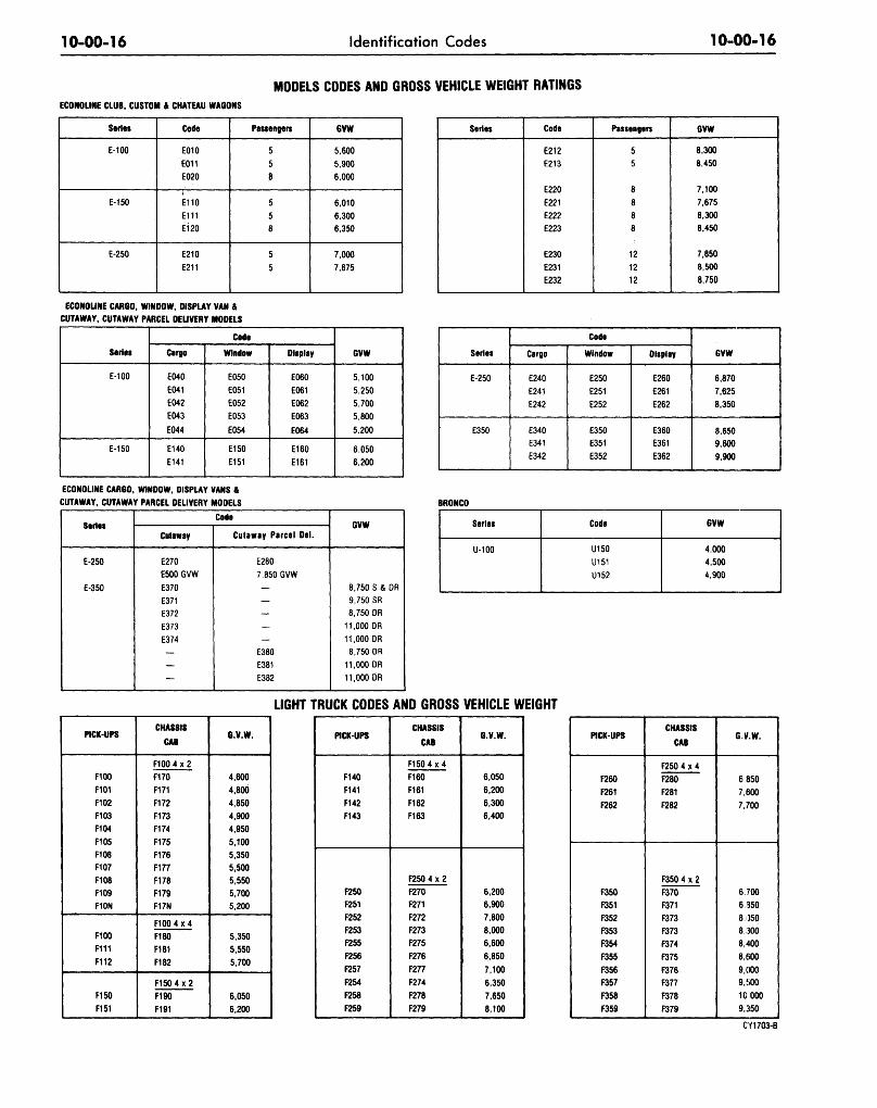
MODELS CODES AND GROSS VEHICLE WEIGHT RATINGSECONOLINE CLUB. CUSTOM 4 CHATEAU WAGONS
Series
E-100
E-150
E-250
Code
E010
E011
E020
E110
E111
E120
E210
E211
Passengers
5
5
8
5
5
8
5
5
GVW
5,600
5,900
6,000
6,010
6,300
6,350
7,000
7,675
Series Code
E212
E213
E220
E221
E222
E223
E230
E231
E232
Passengers
55
8
8
8
8
12
12
12
GVW
8,300
8,450
7,100
7,675
8,300
8,450
7,850
8,500
8,750
ECONOUNE CARGO, WINDOW, DISPLAY VAN &CUTAWAY, CUTAWAY PARCEL DEUVERY MODELS
Series
E-100
E-150
Code
Cargo
E040
E041
E042
E043
E044
E140
E141
Window
E050
E051
E052
E053
E054
E150
E151
Display
E060
E061
E062
E063
E064
E160
E161
GVW
5,100
5,250
5,700
5.800
5.200
6,050
6,200
Series
E-250
E350
Code
Cargo
E240
E241
E242
E340
E341
E342
Window
E250
E251
E252
E350
E351
E352
Display
E260
E261
E262
E360
E361
E362
GVW
6,870
7.625
8,350
8.650
9,600
9,900
ECONOLINE CARGO, WINDOW, DISPLAY VANS 4
CUTAWAY, CUTAWAY PARCEL DEUVERY MODELS BRONCO
Series
E-250
E-350
Code
Cutaway
E270
E500 GVW
E370
E371
E372
E373
E374
Cutaway Parcel Del.
E280
7,850 GVW
E380
E381
E382
GVW
8,750 S & OR
9,750 SR
8,750 DR
11,000 DR
11,000 DR
8,750 DR
11,000 DR
11,000 DR
Series
U-100
Code
U150
U151
U152
GVW
4,000
4,500
4,900
LIGHT TRUCK CODES AND GROSS VEHICLE WEIGHT
PICK-UPS
F100
F101
F102
F103
F104
F105
F108F107
F108
F109
F10N
F100
F111
F112
F150
F151
CHASSIS
CAB
F100 4 x 2
F170
F171
F172
F173
F174
F175
F176
F177
F178
F179F17N
F100 4 x 4
F180
F181
F182
F1504X2
F190
F191
G.V.W.
4,600
4,800
4,850
4,900
4.950
5,100
5,350
5,500
5,550
5,700
5,200
5,350
5,550
5,700
6,050
6,200
PICK-UPS
F140
F141
F142
F143
F250F251
F252
F253
F255
F256
F257
F254
F258
F259
CHASSIS
CAB
F150 4 x 4
F160
F161
F162
F163
F250 4 x 2
F270
F271
F272
F273
F275
F276
F277
F274
F278
F279
G.V.W.
6,050
6,200
6,3006,400
6,200
6,900
7,800
8.000
6,600
6,850
7,100
6,350
7,650
8,100
PICK-UPS
F260
F261
F262
F350
F351
F352
F353
F354
F355
F356
F357
F358
F359
CHASSIS
CAB
F250 4 x 4
F280
F281
F282
F350 4 x 2
F370
F371
F373
F373
F374
F375
F376
F377
F378
F379
G.V.W.
6 850
7,600
7,700
6.700
6 950
8 050
8,300
8,400
8,600
9,000
9,500
10 000
9,350
CY1703-B
10-00-17 Identification Codes 10-00-17
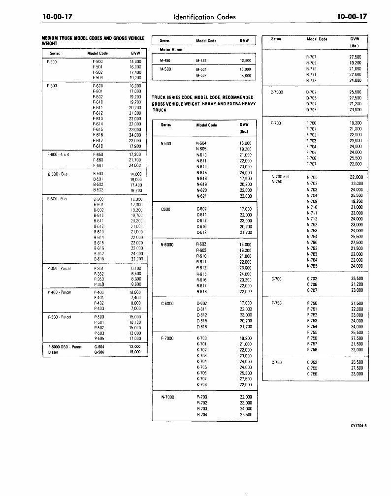
MEDIUM TRUCK MODEL CODES AND GROSS VEHICLEWEIGHT
Series
F-500
F-600
F-600 - 4 x 4
B-500-Bus
B-600 • Bus
P-350 - Parcel
P-400 - Parcel
P-500 • Parcel
P-5000 DSO - ParcelDiesel
Model Code
F-500
F-501F-502F-503
F-600F-601F-602F-610F-611F-612F-613F-614F-615F-616f-617F-618
F-650F-660F-661
B-500B-501B-502B-503
B-600B-601B-602B-610B-611
B-612B-613B-614
B-615B-616B-617B-618
P-351P-352P-353P-350
P-400P-401P-402P-403
P-500P-501P-502P-503P-505
G-504G-506
GVW
14,00016,00017,40019,200
16,00017,00019,20019,70020,20021,00022,00022,00023,00024,00022,00017.900
17,20021,70024.000
14,00016,00017,40019,200
16,00017,00019,2001S.70020,20021,00021,00022,00022,00023,00024,00022,000
6,1006,5008,0008,000
10,0007,4008,0007,000
15,00010,10015,00012,00017,000
12,00015,000
Series
Motor Home
M-450
M-500
Model Code
M-452
M-504
M-507
GVW
12,500
15,000
14,000
TRUCK SERIES COOE. MODEL CODE. RECOMMENDED
GROSS VEHICLE WEIGHT HEAVY AND
TRUCK
Series
N-600
C600
N-6000
C-6000
F-7000
N-7000
Model Code
N-604
N-605
N-610
N-611
N-612
N-615
N-618
N-619
N-620
N-621
C-602
C-611
C-612
C-616C-617
R-602
R-603
R-610
R-611
R-612
R-615R-616R-617
R-618
D-602
D-611
D-612
D-615
D-616
K-700K-701
K-702
K-703K-704
K-705K-706K-707
K-708
R-700
R-702
R-703
R-704
EXTRA HEAVY
GVW
(lbs.)
16.000
19.200
21,000
22,000
23,000
24,000
17,900
20,200
22,000
22,000
17,000
22,00023,000
20,200
21,200
16,000
19,200
21,000
22,000
23,000
24,000
20,200
22,000
22,000
17,000
22,000
23,000
20,200
21,200
19,200
21,000
22,000
23,000
24,000
24,000
25,50027,500
22,000
22,000
23,00024,000
25,500
Series
C-700O
F-700
N-700andN-750
C-700
F-750
C-750
Model Code
R-707
R-709
R-710R-711
R-712
D-702
D-705D-707
D-708
F-700
F-701
F-702
F-703
F-704F-705
F-706F-707
N-700
N-702
N-703N-704
N-709
N-710N-711
N-712
N-752
N-753
N-754
N-760
N-762
N-763N-764
N-765
C-702
C-706C-707
F-750
F-751
F-752
F-753F-754
F-755
F-756F-757
F-758
C-7-52
C-755
C-756
GVW
(lbs.)
27,50019,200
21,00022,000
24,000
25,500
27.500
21,200
23,000
19,200
21,000
22,000
23,000
24,00024,000
25,50022,000
22,000
23,000
24,000
25,500
19,200
21,000
22,000
24,000
23,000
24,000
25,500
27,500
21,500
22,000
22,000
24,000
25,500
21,200
23,000
21,500
22,000
23.000
24,000
24,000
25,500
27,500
21,500
22,000
25,500
27,500
23,000
CY1704-B
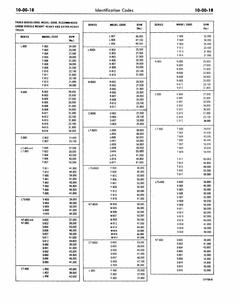
10-00-18 Identification Codes 10-00-18
TRUCK SERIES CODE, MODEL CODE, RECOMMENDED
GROSS VEHICLE WEIGHT HEAVY AND EXTRA HEAVY
TRUCK
SERIES
L-800
N-800
C-800
LT-800 andLT-880
LTS-800
NT-800 andNT-880
CT-800
MODEL CODE
F-802
F-803
F-804
F-805
F-806
F-808
F-809
F-810
F-811
F-812
F-813F-814
N-802
N-803N-804
N-805
N-806
N-808
N-811
N-812
N-813
N-814
N-815N-816
C-802C-807
T-800
T-802
T-804
T-806
T-807
T-811
T-812
T-880
T-881
T-882
T-883
T-884
T-885
V-800
V-804
V-805
V-809V-810
S-800
S-802S-804
S-806S-807
S-811S-812S-880
S-881S-882
S-883
S-884
S-885
L-800
L-802
L-806
GVW(lbs.)
24,500
25,500
27,500
29,000
31,000
34,000
31,000
22,100
31,800
22,100
31,800
34.000
24,500
25,500
27,500
29,000
31,000
34,000
31,000
22.100
31.800
22.100
31,800
34,000
27,50025,100
37,000
39,000
43,000
46,000
50,000
41,000
44,800
39,000
41,000
43,000
44,800
46,000
41,000
39.000
46,000
50,000
41.000
44.000
37.000
39,000
43.000
46,000
50.000
41.000
44.80039,000
41,000
43.00044.800
46,000
41,000
43,000
39,000
42,000
SERIES
L-8000
N-8000
C-8000
LT-8000
LTS-8000
NT-8000
CT-8000
L-900
MODEL CODE
L-807
L-808
L-809
K-802
K-803
K-805
K-806K-807
K-808
K-812
K-813
R-802
R-803
R-805
R-806
R-807
R-808
R-810R-811
D-802
D-806D-807
D-808
U-800
U-805U-806U-807
U-808U-809
U-810
U-815
U-816U-817
Y-800
Y-804
Y-805
Y-806
Y-807
Y-808
Y-812
Y-814
Y-818
W-800
W-805
W-806
W807
W-808
W-812
W-814
W-815W-816W-817
Q-800
Q-802
Q-803
Q-805
Q-807
Q-808
Q-809
F-900
F-902
F-905
GVW(lbs.)
46,000
47.100
48,000
25,500
27,500
31,000
32,00034,000
35,000
23,100
31,800
25,500
27,500
31,000
32,000
34,000
35,000
23,100
31,800
27.500
25.100
32,000
35,000
39,000
46,00050,00050,000
54,00060,00055,00041,000
44,800
61,000
39,000
46,000
50,000
50,000
52,000
54,000
60,000
64,000
41,000
39,000
46.000
50,000
50,000
54,000
41,000
44,80055,00060,00061,000
43,000
39,000
45,000
41,000
46,000
47,100
48,000
25,500
27,500
31,000
SERIES
N-900
C-900
L T-900
LTS-900
NT-900
MODEL CODE
F-906
F-908
F-909
F 912
F-913
F 914
N-900
N-902
N-905
N-906
N-908
N-909
N-911N-912
C-904
C-906
C-907
C-910
C 912
C-913
C-914
C 915
T-900
T-902
T-904
T-906
T-907
T-908
T-909
T 911
T-914
T 915
T-916
T-917
V-900
V-904
V-905
V-906
V-907
V-908
V-909
V-911
V-912
V-913
V-914
V-918
V-919
V-920
S-900
S-902
S-904
S906
S-907
S-909
S-914
S-915
S916
GVW(lbs.)
32,000
34,000
35,000
23,100
31,800
31,000
25,500
27,500
31,000
32,000
34,000
35,000
23,10031,300
27,500
31,000
32,000
34,000
36,000
31,000
25.100
38,000
39,000
41,000
43,000
46,000
50,000
50.000
54.000
60,000
44.800
48.000
52,000
58,000
39.000
46,000
50,000
50,000
52,000
54,000
56,000
58,000
60,000
62,000
64,000
41,000
54,000
48,000
39.000
41,000
43,000
46,000
50,000
154.000
44,800
48,000
52.000
CY1705-B
10-00-19 Identification Codes 10-00-19
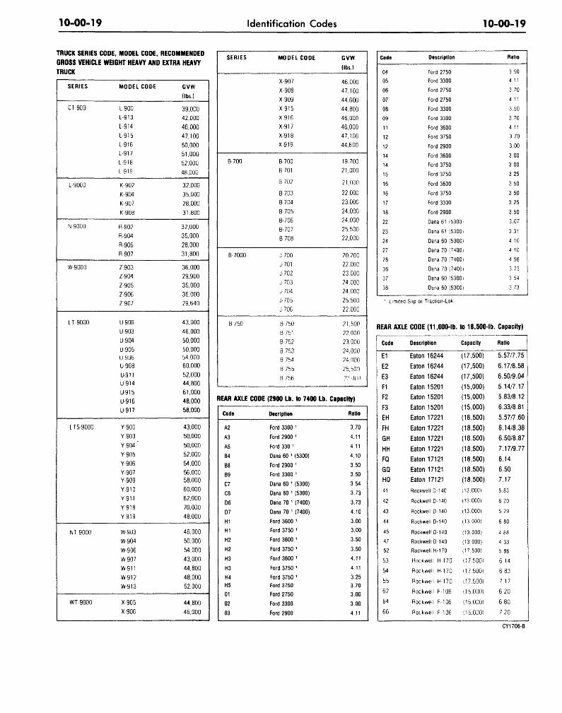
TRUCK SERIES CODE, MODEL CODE, RECOMMENDED
GROSS VEHICLE WEIGHT HEAVY AND EXTRA HEAVY
TRUCK
SERIES
CT-900
L-9000
N-9000
W-9000
LT-9000
LTS-9000
NT-9000
WT-9000
MODEL CODE
L-900
L-913
1-914
L 915
L-916
L 917
L-918
1-919
K-902
K-904
K-907
K-908
R-902
R-904
R-906
R-907
Z-903
Z-904
Z905
Z-906
Z 907
U-900
U903
U904
U905U9U6
U908
U911U-914
U-915
U-916
U-917
Y-900
Y-903
Y-904"
Y-905
Y-906
Y-907Y-909
Y-910
Y 911
Y-918
Y-919
W-903
W-904
W906
W-907
W-911
W-912
W-913
X-905
X-906
GVW
(lbs.)
39,000
42,000
46,000
47,100
50.000
51,000
52,000
48,000
32,000
35.000
28,000
31.800
32,000
35,000
28.000
31.800
36,000
29.900
35.000
36,000
29.640
43.000
46,000
50,000
50,000b4,000
60.000
52.000
44.800
61.000
48,000
58.000
43,000
50,000
50,000
52,000
54,000
56.00058,000
60,000
62,000
70,000
48,000
46,000
50.000
54,000
43,000
44,800
48,000
52,000
44,800
46,000
SERIES
B-700
B-7000
B 750
MODEL CODE
X-907
X-908
X909
X 915
X-916
X 917
X-918
X-919
B-700
B-701
B 702
B-703
B-704
B-705
B-706
B-707
B-708
J-700
J 701
J-702
J 703
J-704
J-705
J 706
B-750
B 751
B-752
B 753
B-754
B 755
B 756
GVW
(lbs.)
46,000
47,100
44,600
44,800
46.000
46,000
47,100
44,600
19,700
21,000
21,000
22,000
23.000
24.000
24,000
25,500
22,000
20,200
22,000
23,000
24,000
24.000
25,500
22,000
21,500
22,000
23,000
24,000
24,000
25,b00
2?.DD0
REAR AXLE CODE (2900 Lb. to 7400 Lb. Capacity)
Code
A2
A3
A5
B4
B8
B9
C7
C8
D6
D7
H1
H1
H2
H2
H3
H3
H4H5
01
02
03
Decription
Ford 3300 1
Ford 2900 1
Ford 330 1
Dana 60 1 (5300)
Ford 2900 1
Ford 3300 1
Dana 60 1 (5300)
Dana 60 1 (5300)
Dana 70 1 (7400)
Dana 70 1 (7400)
Ford 3600 1
Ford 3750 1
Ford 3600 1
Ford 3750 1
Ford 3600 1
Ford 3750 1
Ford 3750 1
Ford 3750
Ford 2750
Ford 3300
Ford 2900
Ratio
3.70
4.11
4.11
4.10
3.50
3.50
3.54
3.73
3.73
4.10
3.00
3.00
3.50
3.50
4.11
4.11
3.25
3.70
3.00
3.00
4.11
Code
04
05
06
07
08
09
11
12
12
14
14
15
16
16
17
18
22
23
24
27
28
36
37
38
Description
Ford 2750
Ford 3300
Ford 2750
Ford 2750
Ford 3300
Ford 3300
Ford 3600
Ford 3750
Ford 2900
Ford 3600
Ford 3750
Ford 3750
Ford 3600
Ford 3750
Ford 3300
Ford 2900
Dana 61 (5300)
Dana 61 (5300)
Dana 60 (5300)
Dana 70 (7400)
Dana 70 (7400)
Dana 70 (7400)
Dana 60 (5300)
Dana 60 (5300)
Ratio
3 50
4 11
3 70
4 11
3.50
3 70
4.11
3.70
3.00
3 00
300
3 25
350
3.50
3.25
350
3.07
3.31
4.10
4.10
4.56
3 73
3 54
3.73
Limited-Slip or Traction-Lok
REAR AXLE CODE (11,000-lb.
Code
E1
E2
E3F1
F2
F3
EH
FH
GH
HH
FQ
GQ
HQ
41
42
43
44
45
47
52
53
54
55
62
64
66
Description
Eaton 16244
Eaton 16244
Eaton 16244
Eaton 15201
Eaton 15201
Eaton 15201
Eaton 17221
Eaton 17221
Eaton 17221
Eaton 17221
Eaton 17121
Eaton 17121
Eaton 17121
Rockwell D-140
Rockwell D-140
Rockwell D-140
Rockwell D-140
Rockwell D-140
Rockwell D-140
Rockwell H-170
Rockwell H-170
Rockwell H-170
Rockwell H-170
Rockwell F 106
Rockwell F 106
Rockwell F 106
to 18,500-lb.
Capacity
(17,500)
(17,500)
(17,500)
(15,000)
(15,000)
(15,000)
(18,500)
(18,500)
(18,500)
(18,500)
(18,500)
(18,500)
(18,500)
113.000)
(13.000)
(13.000)
(13.000)
(13.000)
(13,000)
(17,500)
(17,500)
(17,500)
(17,500)
(15.000)
(15,000)
(15,000)
Capacity)
Ratio
5.57/7.75
6.17/8.58
6.50/9.04
5.14/7.17
5.83/8.12
6.33/8.81
5.57/7.60
6.14/8.38
6.50/8.87
7.17/9.77
6.14
6.50
7.17
5.83
6.20
5.29
680
4.88
4.33
5.86
6 14
6 83
7 17
6 20
6 80
7 20
CY1706-B
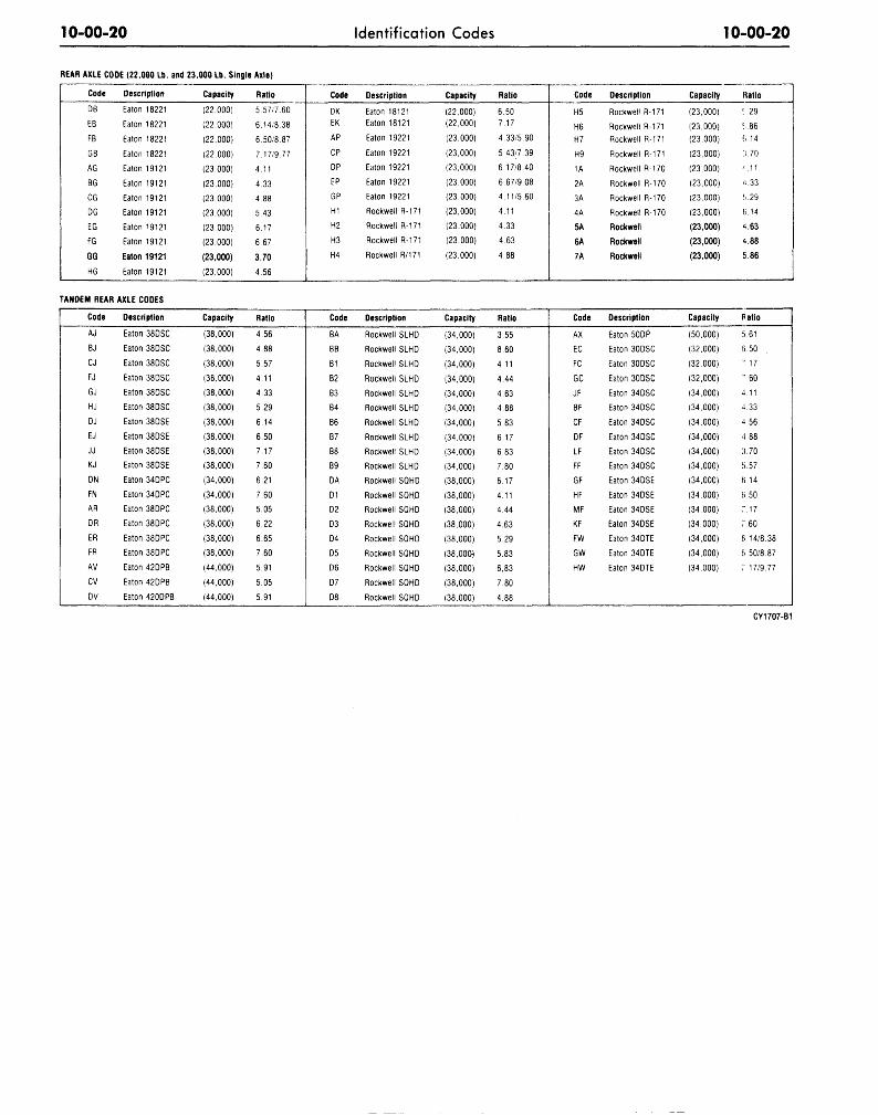
10-00-20 Identification Codes 10-00-20
REAR AXLE CODE (22.000 Lb.
Code
DB
EB
FB
GB
AG
BG
CG
DG
EG
FG
GG
HG
Description
Eaton 18221
Eaton 18221
Eaton 18221
Eaton 18221
Eaton 19121
Eaton 19121
Eaton 19121
Eaton 19121
Eaton 19121
Eaton 19121
Eaton 19121
Eaton 19121
and 23,000 Lb. Single Axle)
Capacity
(22.000)
(22,000)
(22.000)
(22.000)
(23,000)
(23,000)
(23,000)
(23,000)
(23,000)
(23.000)
(23,000)
(23,000)
Ratio
5.57/7.60
6.14/8 38
6.50/8.87
7.17/9.77
4.11
4.33
4.88
5.43
6.17
6.67
3.70
4.56
Code
DKEK
AP
CP
DP
EP
GP
H1
H2
H3
H4
Description
Eaton 18121
Eaton 18121
Eaton 19221
Eaton 19221
Eaton 19221
Eaton 19221
Eaton 19221
Rockwell R-171
Rockwell R-171
Rockwell R-171
Rockwell R/171
Capacity
(22,000)
(22,000)
(23,000)
(23,000)
(23,000)
(23,000)
(23,000)
(23,000)
(23,000)
(23,000)
(23,000)
Ratio
6.50
7.17
4.33/5.90
5.43/7.39
6.17/8.40
6.67/9.08
4.11/5.60
4.11
4.33
4.63
4.88
Code
H5
H6H7
H9
1A
2A
3A
4A
5A
6A
7A
Description
Rockwell R-171
Rockwell R-171
Rockwell R-171
Rockwell R-171
Rockwell R-170
Rockwell R-170
Rockwell R-170
Rockwell R-170
Rockwell
Rockwell
Rockwell
Capacity
(23,000)
(23,000)
(23,000)
(23,000)
(23,000)
(23,000)
(23,000)
(23,000)
(23,000)
(23,000)
(23,000)
Ratio
f..29
1.66
fi.14
3.70
O 1
a. 33
J..29
6.14
4.63
4.88
5.86
TANDEM REAR AXLE CODES
Code
AJ
BJ
CJ
FJ
GJ
HJ
DJ
EJ
JJ
KJ
DN
FN
AR
DR
ER
FR
AV
CV
DV
Description
Eaton 38DSC
Eaton 38DSC
Eaton 38DSC
Eaton 38DSC
Eaton 38DSC
Eaton 38DSC
Eaton 38DSE
Eaton 38DSE
Eaton 38DSE
Eaton 38DSE
Eaton 34DPC
Eaton 34DPC
Eaton 38DPC
Eaton 38DPC
Eaton 38DPC
Eaton 38DPC
Eaton 42DPB
Eaton 42DPB
Eaton 420DPB
Capacity
(38,000)
(38,000)
(38,000)
(38,000)
(38,000)
(38,000)
(38,000)
(38,000)
(38,000)
(38,000)
(34,000)
(34,000)
(38,000)
(38,000)
(38,000)
(38,000)
(44,000)
(44,000)
(44,000)
Ratio
4.56
4.88
5.57
4.11
4.33
5.29
6.14
6.50
7.17
7.60
6.21
7.60
5.05
6.22
6.65
7.60
5.91
5.05
5.91
Code
BA
BB
B1
B2
B3
B4
B6
B7
B8
B9
DA
D1
D2
D3
D4
D5
D6
D7
D8
Description
Rockwell SLHD
Rockwell SLHD
Rockwell SLHD
Rockwell SLHD
Rockwell SLHD
Rockwell SLHD
Rockwell SLHD
Rockwell SLHD
Rockwell SLHD
Rockwell SLHD
Rockwell SQHD
Rockwell SQHD
Rockwell SQHD
Rockwell SQHD
Rockwell SQHD
Rockwell SQHD
Rockwell SQHD
Rockwell SQHD
Rockwell SQHD
Capacity
(34,000)
(34,000)
(34,000)
(34,000)
(34,000)
(34,000)
(34,000)
(34,000)
(34,000)
(34,000)
(38,000)
(38,000)
(38,000)
(38,000)
(38,000)
(38,000)
(38,000)
(38,000)
(38,000)
Ratio
3.55
8.60
4.11
4.44
4.63
4.88
5.83
6.17
6.83
7.80
6.17
4.11
4.44
4.63
5.29
5.83
6,83
7.80
4.88
Code
AX
EC
FC
GCJF
BF
CF
DF
LF
FF
GF
HF
MF
KF
FW
GW
HW
Description
Eaton 50DP
Eaton 30DSC
Eaton 30DSC
Eaton 30DSC
Eaton 34DSC
Eaton 34DSC
Eaton 34DSC
Eaton 34DSC
Eaton 34DSC
Eaton 34DSC
Eaton 34DSE
Eaton 34DSE
Eaton 34DSE
Eaton 34DSE
Eaton 34DTE
Eaton 34DTE
Eaton 34DTE
Capacity
(50,000)
(32,000)
(32,000)
(32,000)
(34,000)
(34,000)
(34,000)
(34,000)
(34,000)
(34,000)
(34,000)
(34,000)
(34,000)
(34,000)
(34,000)
(34,000)
(34,000)
Patio
5.61
6.50
"' 17
"'.60
4.11
4.33
4.56
4.88
3.70
5.57
6.14
6.50
7.17
760
6.14/8.38
6 50/8.87
7 17/9.77
CY1707-B1
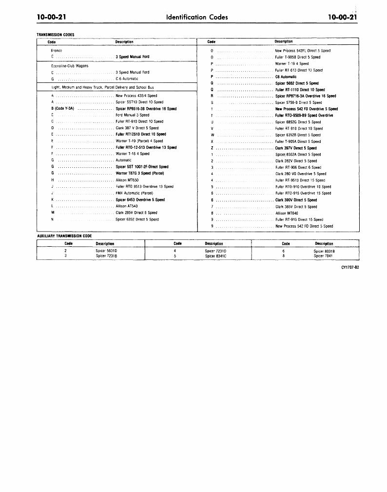
10-00-21 Identification Codes 10-00-21
TRANSMISSION CODES
Code
Bronco
C
Econoline-Club Wagons
C
G •
Light, Medium and Heavy Truck,
A
A
B (Code Y-3A)
C
C
D
E
E :
F
F
G
G
G
H
J
J
K
L
M
N
Description
3 Speed Manual Ford
3 Speed Manual Ford
C-6 Automatic
Parcel Delivery and School Bus
New Process 435/4 Speed
Spicer SST10 Direct 10 Speed
Spicer RP8516-3B Overdrive 16 Speed
Ford Manual 3 Speed
Fuller RT-610 Direct 10 Speed
Clark 387 V Direct 5 Speed
Fuller RT12510 Direct 10 Speed
Warner T-19 (Parcel) 4 Speed
Fuller RTO-12-513 Overdrive 13 Speed
WarnerT-18 4 Speed
Automatic
Spicer SST 1007-2F-Direct Speed
Warner T87G 3 Speed (Parcel)
Allison MT650
Fuller RTO 9513 Overdrive 13 Speed
FMX Automatic (Parcel)
Spicer 6453 Overdrive 5 Speed
Allison AT540
Clark 285V Direct 5 Speed
Spicer 6352 Direct 5 Speed
Code
0
0
p
p
p
Q
Q
R
S
T
T
U
V
wX
z1
2
3
4
4
5
6
6
7
8
9
9
Description
New Process 542FL Direct 5 Speed
Fuller T-905B Direct 5 Speed
Warner T-19 4 Speed
Fuller RT 6.13 Direct 13 Speed
C6 Automatic
Spicer 5652 Direct 5 Speed
Fuller RT-1110 Direct 10 Speed
Spicer RP8716-3A Overdrive 16 Speed
Spicer 5756-B Direct 5 Speed
New Process 542 FO Overdrive 5 Speed
Fuller RT0-9509-B9 Speed Overdrive
Spicer 6852G Direct 5 Speed
Fuller RT-910 Direct 10 Speed
Spicer 6352B Direct 5 Speed
Fuller T-905A Direct 5 Speed
Clark 397V Direct 5 Speed
Spicer-8552A Direct 5 Speed
Clark 282V Direct 5 Speed
Fuller RT-906 Direct 6 Speed
Clark 280 VO Overdrive 5 Speed
Fuller RT-9513 Direct 15 Speed
Fuller RTO-910 Overdrive 10 Speed
Fuller RTO-915 Overdrive 15 Speed
Clark 390V Direct 5 Speed
Clark 385V Direct 5 Speed
Allison MT640
Fuller RT-915 Direct 15 Speed
New Process 542 FD Direct 5 Speed
AUXILIARY TRANSMISSION CODE
Code
2
3
Description
Spicer 5831D
Spicer 7231B
Code
4
5
Description
Spicer 7231D
Spicer 8341C
Code
68
Description
Spicer 8031BSpicer 7041
CY1707-B2
11-01-1 Wheels and Tires 11-01-1
Wheels and TiresGROUP
11PART 11-01 Page
General Wheel and Tire Service 11-01-1
PART 11-02
Wheels and Tires-
Drop Center Rim 11-02-1
PART 11-03
Wheels and Tires—
Two-Piece Rims 11-03-1
PART 11-04
Wheels and Tires—
Three-Piece Rims 11-04-1
PART 11-10
Wheel Hubs and Bearings-
Front (Except Front Drive) 11-10-1
PART 11-11
Wheel Hubs and
Bearings-Rear 11-11-1
PART 11-12
Wheel Hubs and Bearings-
Front Wheel Drive 11-12-1
PART 11-14
Wheel Hubs and Bearings-
Rear (Full Floating Axle) 11-14-1
PART 11-01 General Wheel and Tire ServiceApplies to All Models
COMPONENT INDEX
FRONT WHEEL BEARINGSAdjustments
Maintenance
Cleaning and Inspection
Page
01-3
01-3
01-3
COMPONENT INDEX
TIRES INSPECTION
WHEELS
Balancing
Cleaning and Inspection
Page
01-3
01-3
01-3
SAFETY
SAFETY PRECAUTIONS WHENSERVICING TRUCK TIRES
CAUTION AND SAFETY FIRSTare bywords when handling tires,particularly truck tires. Careful attentionto the suggestions that follow mayprevent crippling injuries, or even death.Make it a rule to respect the terrific forcecontained in an inflated tire. You may beglad some day that you did.
Prepare for any tire repair operationin a safe and efficient way. In changingtires on drop center wheels, remove thewheel and tire from the truck, aschanging tires with the wheel on the
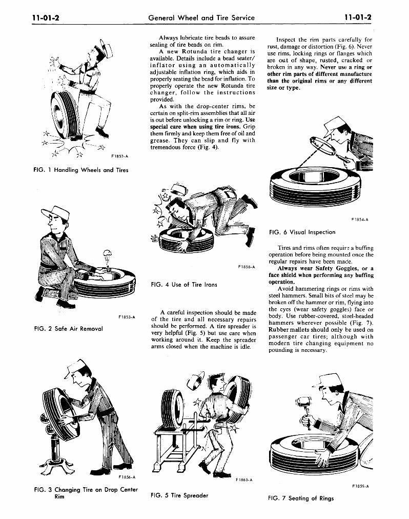
truck is hazardous, more difficult, andtakes more time. In servicing of all tiresuse caution not to drop them (or thewheels or assemblies) on the feet, handsor body, or heavily on the floor (Fig. 1).Practice good methods of lifting; use yourlegs as well as your arms and your body.This will help to prevent painful internalinjury. When carrying tires or wheelsdon't step in oil or grease. Keep the floorclean and dry.
Demounting tires from wheels or rimsrequires special care. Tires on drop centerrims are best handled on a wheel holderor tire-changing machine (Fig. 3).
Deflating a tire properly is veryimportant to your safety. First, reducethe pressure as much as you possibly canby pushing the valve core plunger. Onlythen should you remove the valve core.Keep your eyes away from the valve: Fig.2 shows the safe way to do it.
This will prevent cuts on hands andwrists and will make it unnecessary to usea mallet for seating the tire.
Use only standard tire mounting toolsand equipment. The use of makeshifttools, screwdrivers or pliers to force tireson or off rims or wheels is dangerous.
11-01-2 General Wheel and Tire Service 11-01-2
FIG. 1 Handling Wheels and Tires
F1853-A
FIG. 2 Safe Air Removal
F1856-A
Always lubricate tire beads to assuresealing of tire beads on rim.
A new Rotunda tire changer isavailable. Details include a bead seater/inflator using an automaticallyadjustable inflation ring, which aids inproperly seating the bead for inflation. Toproperly operate the new Rotunda tirechanger, follow the instructionsprovided.
As with the drop-center rims, becertain on split-rim assemblies that all airis out before unlocking a rim or ring. Usespecial care when using tire irons. Gripthem firmly and keep them free of oil andgrease. They can slip and fly withtremendous force (Fig. 4).
Inspect the rim parts carefully forrust, damage or distortion (Fig. 6). Neveruse rims, locking rings or flanges whichare out of shape, rusted, cracked orbroken in any way. Never use a ring orother rim parts of different manufacturethan the original rims or any differentsize or type.
F1858-A
FIG. 4 Use of Tire Irons
A careful inspection should be madeof the tire and all necessary repairsshould be performed. A tire spreader isvery helpful (Fig. 5) but use care whenworking around it. Keep the spreaderarms closed when the machine is idle.
F1854-A
FIG. 6 Visual Inspection
Tires and rims often require a buffingoperation before being mounted once theregular repairs have been made.
Always wear Safety Goggles, or aface shield when performing any buffingoperation.
Avoid hammering rings or rims withsteel hammers. Small bits of steel may bebroken off the hammer or rim, flying intothe eyes (wear safety goggles) face orbody. Use rubber-covered, steel-headedhammers wherever possible (Fig. 7).Rubber mallets should only be used onpassenger car tires; although withmodern tire changing equipment nopounding is necessary.
F1860-A
FIG. 3 Changing Tire on Drop CenterRim
F1859-A
FIG. 5 Tire Spreader FIG. 7 Seating of Rings
11-01-3 General Wheel and Tire Service 11-01-3
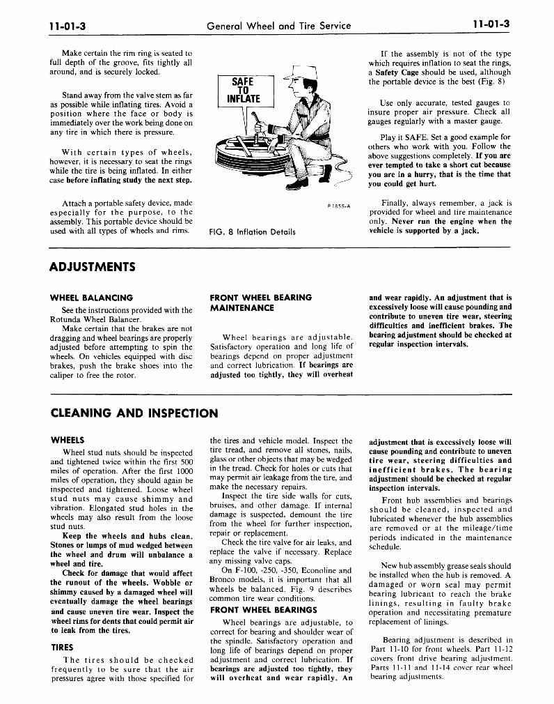
Make certain the rim ring is seated tofull depth of the groove, fits tightly allaround, and is securely locked.
Stand away from the valve stem as faras possible while inflating tires. Avoid aposition where the face or body isimmediately over the work being done onany tire in which there is pressure.
With cer ta in types of wheels,however, it is necessary to seat the ringswhile the tire is being inflated. In eithercase before inflating study the next step.
Attach a portable safety device, madeespecially for the purpose, to theassembly. This portable device should beused with all types of wheels and rims.
F1855-A
FIG. 8 Inflation Details
If the assembly is not of the typewhich requires inflation to seat the rings,a Safety Cage should be used, althoughthe portable device is the best (Fig. 8)
Use only accurate, tested gauges toinsure proper air pressure. Check allgauges regularly with a master gauge.
Play it SAFE. Set a good example forothers who work with you. Follow theabove suggestions completely. If you areever tempted to take a short cut becauseyou are in a hurry, that is the time thatyou could get hurt.
Finally, always remember, a jack isprovided for wheel and tire maintenanceonly. Never run the engine when thevehicle is supported by a jack.
ADJUSTMENTS
WHEEL BALANCINGSee the instructions provided with the
Rotunda Wheel Balancer.Make certain that the brakes are not
dragging and wheel bearings are properlyadjusted before attempting to spin thewheels. On vehicles equipped with discbrakes, push the brake shoes into thecaliper to free the rotor.
FRONT WHEEL BEARINGMAINTENANCE
Wheel bearings are adjustable.Satisfactory operation and long life ofbearings depend on proper adjustmentand correct lubrication. If bearings areadjusted too tightly, they will overheat
and wear rapidly. An adjustment that isexcessively loose will cause pounding andcontribute to uneven tire wear, steeringdifficulties and inefficient brakes. Thebearing adjustment should be checked atregular inspection intervals.
CLEANING AND INSPECTION
WHEELS
Wheel stud nuts should be inspectedand tightened twice within the first 500miles of operation. After the first 1000miles of operation, they should again beinspected and tightened. Loose wheelstud nuts may cause shimmy andvibration. Elongated stud holes in thewheels may also result from the loosestud nuts.
Keep the wheels and hubs clean.Stones or lumps of mud wedged betweenthe wheel and drum will unbalance awheel and tire.
Check for damage that would affectthe runout of the wheels. Wobble orshimmy caused by a damaged wheel willeventually damage the wheel bearingsand cause uneven tire wear. Inspect thewheel rims for dents that could permit airto leak from the tires.
TIRES
The t i r e s s h o u l d be checkedfrequently to be sure that the airpressures agree with those specified for
the tires and vehicle model. Inspect thetire tread, and remove all stones, nails,glass or other objects that may be wedgedin the tread. Check for holes or cuts thatmay permit air leakage from the tire, andmake the necessary repairs.
Inspect the tire side walls for cuts,bruises, and other damage. If internaldamage is suspected, demount the tirefrom the wheel for further inspection,repair or replacement.
Check the tire valve for air leaks, andreplace the valve if necessary. Replaceany missing valve caps.
On F-100, -250, -350, Econoline andBronco models, it is important that allwheels be balanced. Fig. 9 describescommon tire wear conditions.
FRONT WHEEL BEARINGSWheel bearings are adjustable, to
correct for bearing and shoulder wear ofthe spindle. Satisfactory operation andlong life of bearings depend on properadjustment and correct lubrication. Ifbearings are adjusted too tightly, theywill overheat and wear rapidly. An
adjustment that is excessively loose willcause pounding and contribute to uneventire wear, steering difficulties andineff ic ient brakes . The bearingadjustment should be checked at regularinspection intervals.
Front hub assemblies and bearingsshould be cleaned, inspected andlubricated whenever the hub assembliesare removed or at the mileage/timeperiods indicated in the maintenanceschedule.
New hub assembly grease seals shouldbe installed when the hub is removed. Adamaged or worn seal may permitbearing lubricant to reach the brakelinings, result ing in faulty brakeoperation and necessitating prematurereplacement of linings.
Bearing adjustment is described inPart 11-10 for front wheels. Part 11-12covers front drive bearing adjustment.Parts 11-11 and 11-14 cover rear wheelbearing adjustments.
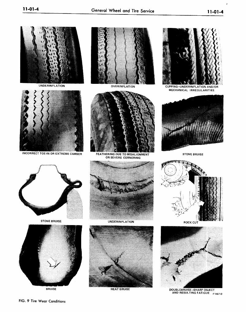
11-01-4 General Wheel and Tire Service 11-01-4
CUPPING-UNDERINFLATION AND/ORMECHANICAL IRREGULARITIES
INCORRECT TOE-IN OR EXTREME CAMBER FEATHERING DUE TO MISALIGNMENTOR SEVERE CORNERING
STONE BRUISE
BRUISE HEAT BRUISE DOUBLEBRUISE-SHARP OBJECTAND RESULTING FATIGUE F 1 4 6 7 .D
FIG. 9 Tire Wear Conditions
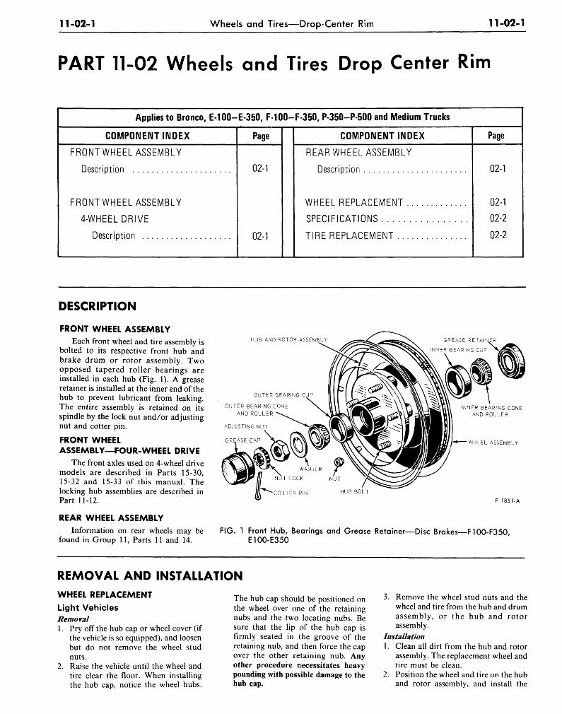
11-02-1 Wheels and Tires—Drop-Center Rim 11-02-1
PART 11-02 Wheels and Tires Drop Center Rim
Applies to Bronco, E-100-E-350, F-100-F-350, P-350-P-500 and Medium Trucks
COMPONENT INDEX
FRONT WHEEL ASSEMBLY
Description
FRONT WHEEL ASSEMBLY
4-WHEEL DRIVE
Description
Page
02-1
02-1
COMPONENT INDEX
REAR WHEEL ASSEMBLY
Description
WHEEL REPLACEMENT
SPECIFICATIONS
TIRE REPLACEMENT
Page
02-1
02-1
02-2
02-2
DESCRIPTION
FRONT WHEEL ASSEMBLYEach front wheel and tire assembly is
bolted to its respective front hub andbrake drum or rotor assembly. Twoopposed tapered roller bearings areinstalled in each hub (Fig. 1). A greaseretainer is installed at the inner end of thehub to prevent lubricant from leaking.The entire assembly is retained on itsspindle by the lock nut and/or adjustingnut and cotter pin.
FRONT WHEELASSEMBLY—FOUR-WHEEL DRIVE
The front axles used on 4-wheel drivemodels are described in Parts 15-30,15-32 and 15-33 of this manual. Thelocking hub assemblies are described inPart 11-12.
REAR WHEEL ASSEMBLYInformation on rear wheels may be
found in Group 11, Parts 11 and 14.
HUB AND ROTOR ASSEMBLY
OUTER BEARING C
OUTER BEARING CONEAND ROLLER
ADJUSTING NUT
GREASE CAP
INNER BEARING CONEAND ROLLER
WHEEL ASSEMBLY
WASHER
NUT LOCK NUT
COTTER PIN HUB BOLT
F 1851-A
FIG. 1 Front Hub, Bearings and Grease Retainer—Disc Brakes—F100-F350E100-E350
REMOVAL AND INSTALLATION
WHEEL REPLACEMENT
Light VehiclesRemoval1. Pry off the hub cap or wheel cover (if
the vehicle is so equipped), and loosenbut do not remove the wheel studnuts.
2. Raise the vehicle until the wheel andtire clear the floor. When installingthe hub cap, notice the wheel hubs.
The hub cap should be positioned onthe wheel over one of the retainingnubs and the two locating nubs. Besure that the lip of the hub cap isfirmly seated in the groove of theretaining nub, and then force the capover the other retaining nub. Anyother procedure necessitates heavypounding with possible damage to thehub cap.
3. Remove the wheel stud nuts and thewheel and tire from the hub and drumassembly, or the hub and rotorassembly.
Installation1. Clean all dirt from the hub and rotor
assembly. The replacement wheel andtire must be clean.
2. Position the wheel and tire on the huband rotor assembly, and install the
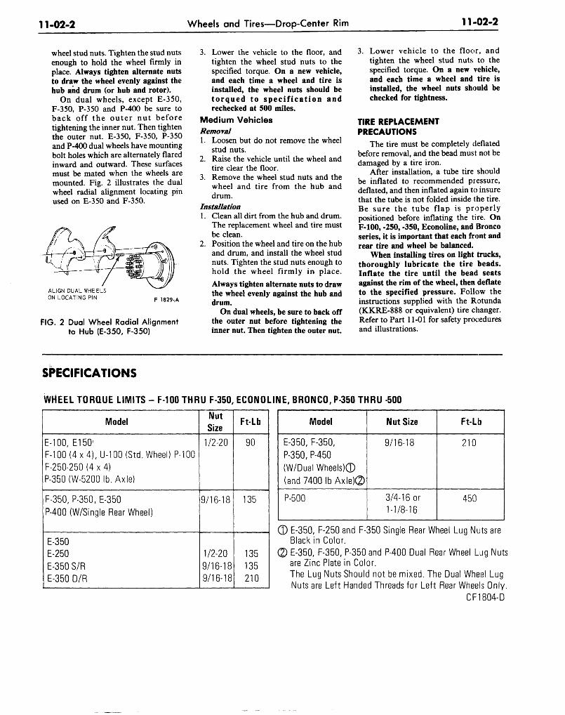
11-02-2 Wheels and Tires—Drop-Center Rim 11-02-2
wheel stud nuts. Tighten the stud nutsenough to hold the wheel firmly inplace. Always tighten alternate nutsto draw the wheel evenly against thehub and drum (or hub and rotor).
On dual wheels, except E-350,F-350, P-350 and P-400 be sure toback off the ou te r nut beforetightening the inner nut. Then tightenthe outer nut. E-350, F-350, P-350and P-400 dual wheels have mountingbolt holes which are alternately flaredinward and outward. These surfacesmust be mated when the wheels aremounted. Fig. 2 illustrates the dualwheel radial alignment locating pinused on E-350 and F-350.
ALIGN DUAL WHEELSON LOCATING PIN F 1829,A
FIG. 2 Dual Wheel Radial Alignmentto Hub (E-350, F-350)
3. Lower the vehicle to the floor, andtighten the wheel stud nuts to thespecified torque. On a new vehicle,and each time a wheel and tire isinstalled, the wheel nuts should betorqued to spec i f icat ion andrechecked at 500 miles.
Medium VehiclesRemoval1. Loosen but do not remove the wheel
stud nuts.2. Raise the vehicle until the wheel and
tire clear the floor.3. Remove the wheel stud nuts and the
wheel and tire from the hub anddrum.
Installation1. Clean all dirt from the hub and drum.
The replacement wheel and tire mustbe clean.
2. Position the wheel and tire on the huband drum, and install the wheel studnuts. Tighten the stud nuts enough tohold the wheel firmly in place.
Always tighten alternate nuts to drawthe wheel evenly against the hub anddrum.
On dual wheels, be sure to back offthe outer nut before tightening theinner nut. Then tighten the outer nut.
3. Lower vehicle to the floor, andtighten the wheel stud nuts to thespecified torque. On a new vehicle,and each time a wheel and tire isinstalled, the wheel nuts should bechecked for tightness.
TIRE REPLACEMENTPRECAUTIONS
The tire must be completely deflatedbefore removal, and the bead must not bedamaged by a tire iron.
After installation, a tube tire shouldbe inflated to recommended pressure,deflated, and then inflated again to insurethat the tube is not folded inside the tire.Be sure the tube flap is properlypositioned before inflating the tire. OnF-100, -250, -350, Econoline, and Broncoseries, it is important that each front andrear tire and wheel be balanced.
When installing tires on light trucks,thoroughly lubricate the tire beads.Inflate the tire until the bead seatsagainst the rim of the wheel, then deflateto the specified pressure. Follow theinstructions supplied with the Rotunda(KKRE-888 or equivalent) tire changer.Refer to Part 11-01 for safety proceduresand illustrations.
SPECIFICATIONS
WHEEL TORQUE LIMITS - F-100 THRU F-350, ECONOLINE, BRONCO, P-350 THRU -500
Model
E-100, E150'F-100 (4 x 4), U-100 (Std. Wheel) P-100F-250-250 (4 x 4)P-350 (W-5200lb. Axle)
F-350, P-350, E-350
P-400 (W/Single Rear Wheel)
E-350E-250E-350 S/RE-350 D/R
NutSize
1/2-20
9/16-18
1/2-209/16-189/16-18
Ft-Lb
90
135
135
135
210
Model
E-350, F-350,P-350, P-450(W/Dual Wheels)©(and 7400 Ib Axle)®
P-500
Nut Size
9/16-18
3/4-16 or
1-1/8-16
Ft-Lb
210
450
E-350, F-250 and F-350 Single Rear Wheel Lug Nuts areBlack in Color.E-350, F-350, P-350 and P-400 Dual Rear Wheel Lug Nutsare Zinc Plate in Color.The Lug Nuts Should not be mixed. The Dual Wheel LugNuts are Left Handed Threads for Left Rear Wheels Only.
CF1804-D
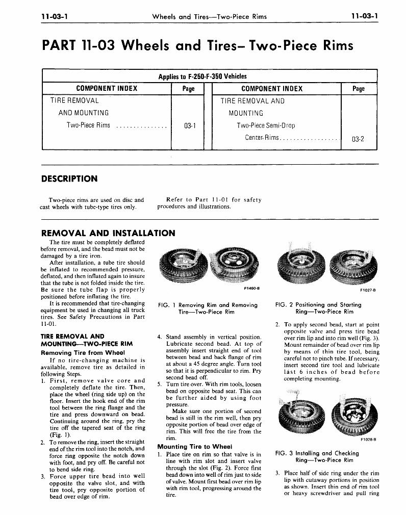
11-03-1 Wheels and Tires—Two-Piece Rims 11-03-1
PART 11-03 Wheels and Tires-Two-Piece Rims
Applies to F-250-F 350 Vehicles
COMPONENT INDEX
TIRE REMOVAL
AND MOUNTING
Two-Piece Rims
Page
03-1
COMPONENT INDEX
TIRE REMOVAL AND
MOUNTING
Two-Piece Semi-Drop
Center. Rims
Page
03-2
DESCRIPTION
Two-piece rims are used on disc andcast wheels with tube-type tires only.
Refer to Part 11-01 for safetyprocedures and illustrations.
REMOVAL AND INSTALLATIONThe tire must be completely deflated
before removal, and the bead must not bedamaged by a tire iron.
After installation, a tube tire shouldbe inflated to recommended pressure,deflated, and then inflated again to insurethat the tube is not folded inside the tire.Be sure the tube flap is properlypositioned before inflating the tire.
It is recommended that tire-changingequipment be used in changing all trucktires. See Safety Precautions in Part11-01.
TIRE REMOVAL ANDMOUNTING—TWO-PIECE RIMRemoving Tire from Wheel
If no tire-changing machine isavailable, remove tire as detailed infollowing Steps.1. First, remove valve core and
completely deflate the tire. Then,place the wheel (ring side up) on thefloor. Insert the hook end of the rimtool between the ring flange and thetire and press downward on bead.Continuing around the ring, pry thetire off the tapered seat of the ring(Fig. 1).
2. To remove the ring, insert the straightend of the rim tool into the notch, andforce ring opposite the notch downwith foot, and pry off. Be careful notto bend side ring.
3. Force upper tire bead into wellopposite the valve slot, and withtire tool, pry opposite portion ofbead over edge of rim.
F1460-B
FIG. 1 Removing Rim and RemovingTire—Two-Piece Rim
4. Stand assembly in vertical position.Lubricate second bead. At top ofassembly insert straight end of toolbetween bead and back flange of rimat about a 45 degree angle. Turn toolso that it is perpendicular to rim. Prysecond bead off.
5. Turn tire over. With rim tools, loosenbead on opposite bead seat. This canbe further aided by using footpressure.
Make sure one portion of secondbead is still in the rim well, then pryopposite portion of bead over edge ofrim. This will free the tire from therim.
Mounting Tire to Wheel1. Place tire on rim so that valve is in
line with rim slot and insert valvethrough the slot (Fig. 2). Force firstbead down into well of rim just to sideof valve. Mount first bead over rim lipwith rim tool, progressing around thetire.
F1027B
FIG. 2 Positioning and StartingRing—Two-Piece Rim
2. To apply second bead, start at pointopposite valve and press tire beadover rim lip and into rim well (Fig. 3).Mount remainder of bead over rim lipby means of thin tire tool, beingcareful not to pinch tube. If necessary,insert second tire tool and lubricatelast 6 inches of bead beforecompleting mounting.
F1028B
FIG. 3 Installing and CheckingRing—Two-Piece Rim
3. Place half of side ring under the rimlip with cutaway portions in positionas shown. Insert thin end of rim toolor heavy screwdriver and pull ring

11-03-2 Wheels and Tires—Two-Piece Rims 11-03-2
Rim Tool
" C " RING
vVORK IND'RECTIONC=ARROW
SAFETY BEAD HUMP
F1473-B
FIG. 4 Two-Piece Split Ring—Light Truck
outward toward centered position.Strike with mallet to start ring overrim lip, then strike remaining portionto force it over rim lip.
TIRE REMOVAL ANDMOUNTING—TWO-PIECESEMI-DROP CENTERRIM—F250-F350
Recent developments make possiblethe removal and mounting of tires fromthis type of wheel-rim combination withmechanical tire-changing equipment. Ifavailable, follow instructions ofequipment manufacturer. Otherwise, usethe following instructions.
This two-piece wheel uses a split C-type ring, as shown in Fig. 4.Removal of Side Ring from Rimwith Tire1. Deflate tire completely and place the
wheel (ring side up) on the floor.2. Break the tire bead free from the rim,
being careful not to damage the bead(Fig. 5).
3. Insert the straight end of the rim toolinto and under the notch in the ring(Fig. 6).
4. Force the tool downward todisengage the ring from the rimgutter. Work the tool around the rim,freeing the ring from the rim, andremove the ring.
5. Turn the wheel over and loosen theopposite tire bead from the rim bydriving the hook end of the rim toolbetween the rim flange and the tirebead. Pry the tire bead away from thetaper, and remove the tire from therim (Fig. 7).
Rim Tools
F1337-B
FIG. 5 Loosening Tire Bead
Mounting Tire to Wheel1. Position the tube in the tire and place
the wheel (gutter side up) on the floor.Soap both beads of the tire andposition the tire on the rim. It isimportant that the tire be soaped wellas it must be forced over the safetybead hump and the rim edge (Fig. 8).
2. Position the ring with the notch about3 inches from the valve stem.
3. Insert the rim tool under the ring ata position approximately 180 degreesfrom the notch and pry tire onto rim.Work the remaining section of rimover the gutter with a second tool.
4. Make certain that the ring is entirelyseated in the gutter. If the ring is notseated correctly as described, it maybe forced off violently, either duringinflation or when the vehicle isoperated.
FIG. 6 Removing Split Ring
Rim Tools
F1340-A
FIG. 7 Removing Tire From Rim
F1341-A
FIG. 8 Installing First Tire Bead onWheel
5. After installation, over-inflate the tireto 75 psi to snap the tire beads overthe bead humps and fully seat the tireagainst the rim and side ring. Deflatethe t ire, then reinflate it torecommended pressure to insure thatthe tube is not folded inside the tire.Be sure the tube flap is properlypositioned before inflating the tire.Always use a cage or safety chainduring initial inflation.
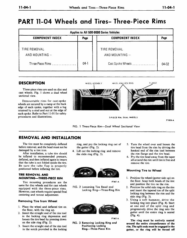
11-04-1 Wheels and Tires—Three-Piece Rims 11-04-1
PART 11-04 Wheels and Tires- Three-Piece Rims
Applies to All 500-9000 Series Vehicles
COMPONENT INDEX
TIRE REMOVAL
AND MOUNTING-
Three-Piece Rims
Page
04-1
COMPONENT INDEX
TIRE REMOVAL
AND MOUNTING-
Cast Spoke Wheels
Page
04-02
DESCRIPTION
Three-piece rims are used on disc andcast wheels. Fig. 1 shows a dual wheelsectional view.
Demountable rims for cast-spokewheels are secured by a ramp at the backedge of each spoke, together with a lugretained by a stud and nut at the edge ofeach spoke. Refer to Part 11-01 for safetyprocedures and illustrations.
WHEEL ASSEMBLY WHEEL RIM LOCK RING FLANGE
3-PIECE RIM, DUAL WHEELS
FIG. 1 Three-Piece Rim—Dual Wheel Sectional View
F1806-A
REMOVAL AND INSTALLATIONThe tire must be completely deflated
before removal, and the bead must not bedamaged by a tire iron.
After installation, a tube tire shouldbe inflated to recommended pressure,deflated, and then inflated again to insurethat the tube is not folded inside the tire.Be sure the tube flap is properlypositioned before inflating the tire.
TIRE REMOVAL ANDMOUNTING—THREE-PIECE RIM
Tire mounting procedures are thesame for disc wheels and for cast wheelsequipped with the three-piece rims.However, cast wheels require special finalcentering and runout adjustment.
Removing Tire from Wheel
1. Place the wheel and deflated tire onthe floor, with the ring up.
2. Insert the straight end of the rim toolin the locking ring depression andloosen the tire bead by pressing downon the side ring (Fig. 2).
3. Insert the straight end of the rim toolin the notch provided in the locking
ring, and pry the locking ring out ofthe gutter (Fig. 2).
4. Lift out the locking ring and removethe slide ring (Fig. 3).
F1461-A
FIG. 2 Loosening Tire Bead andLocking Ring—Three-Ring Rim
F1462-A
FIG. 3 Removing Locking Ring andPositioning LockingRing—Three-Piece Rim
5. Turn the wheel over and loosen thetire bead from the rim by driving thehooked end of the rim tool betweenthe rim flange and the tire bead.
6. Pry the tire bead away from the taperall around the rim until tire is free andremove the tire.
Mounting Tire to Wheel
1. Position the wheel (gutter side up) onthe floor. Soap both beads of the tireand position the tire on the rim.
2. Position the solid side ring on the tireand insert the tapered toe of the splitlocking ring between the rim and theside ring (Fig. 3).
3. Using a soft hammer, drive thelocking ring into place (Fig. 4). Startat one end of the split ring andprogressively drive the ring into thegutter until the entire ring is seated(Fig. 4).
The ring must be entirely seatedaround the entire circumference of therim. The split ends must be engaged in thegutter, or the ring will be forced off
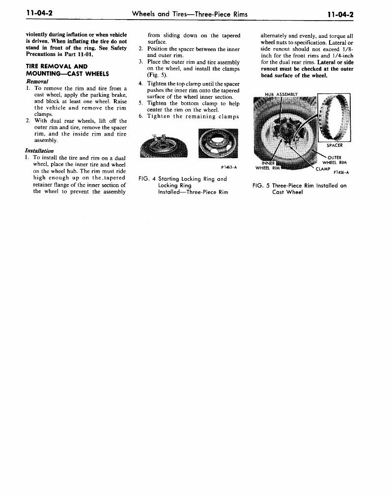
11-04-2 Wheels and Tires—Three-Piece Rims 11-04-2
violently during inflation or when vehicleis driven. When inflating the tire do notstand in front of the ring. See SafetyPrecautions in Part 11-01.
TIRE REMOVAL ANDMOUNTING—CAST WHEELSRemoval1. To remove the rim and tire from a
cast wheel, apply the parking brake,and block at least one wheel. Raisethe vehicle and remove the rimclamps.
2. With dual rear wheels, lift off theouter rim and tire, remove the spacerrim, and the inside rim and tireassembly.
Installation1. To install the tire and rim on a dual
wheel, place the inner tire and wheelon the wheel hub. The rim must ridehigh enough up on the, taperedretainer flange of the inner section ofthe wheel to prevent the assembly
from sliding down on the taperedsurface.
2. Position the spacer between the innerand outer rim.
3. Place the outer rim and tire assemblyon the wheel, and install the clamps(Fig. 5).
4. Tighten the top clamp until the spacerpushes the inner rim onto the taperedsurface of the wheel inner section.
5. Tighten the bottom clamp to helpcenter the rim on the wheel.
6. Tighten the remain ing clamps
F1463-A
FIG. 4 Starting Locking Ring andLocking RingInstalled—Three-Piece Rim
alternately and evenly, and torque allwheel nuts to specification. Lateral orside runout should not exceed 1/8-inch for the front rims and 1/4-inchfor the dual rear rims. Lateral or siderunout must be checked at the outerbead surface of the wheel.
HUB ASSEMBLY
WHEEL
OUTERWHEEL RIM
C L A M P F14S.-A
FIG. 5 Three-Piece Rim Installed onCast Wheel
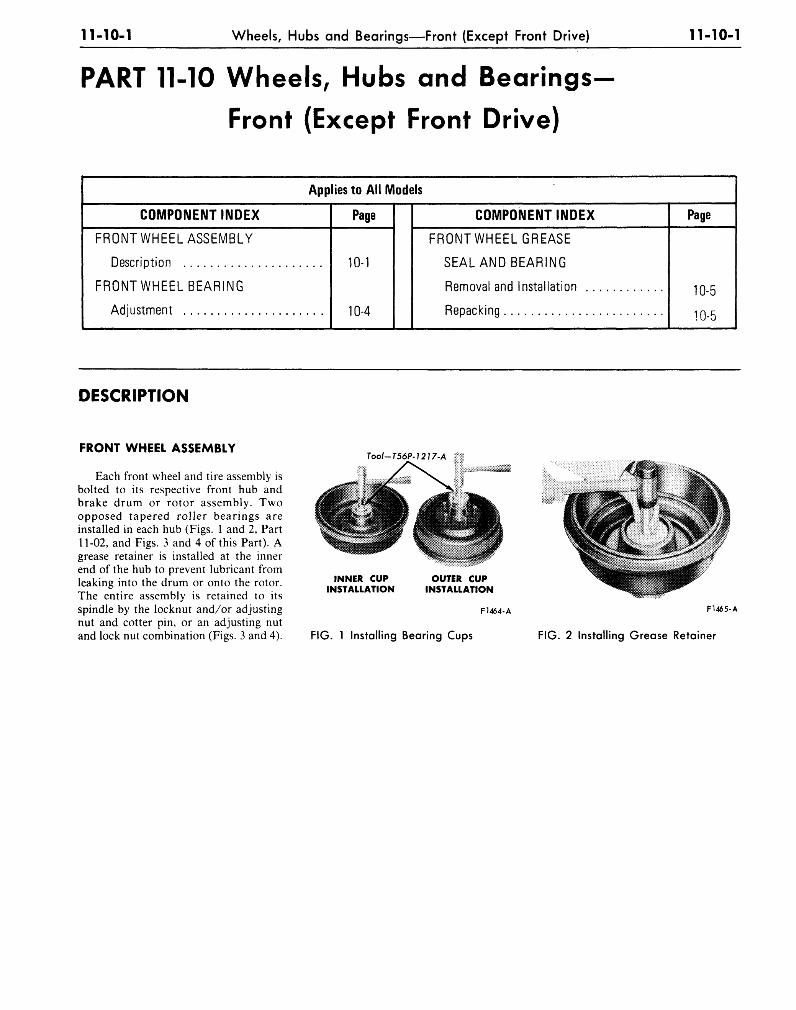
11-10-1 Wheels, Hubs and Bearings—Front (Except Front Drive) 11-10-1
PART 11-10 Wheels, Hubs and Bearings
Front (Except Front Drive)
Applies to All Models
COMPONENT INDEX
FRONT WHEELASSEMBLY
Description
FRONT WHEEL BEARING
Adjustment
Page
10-1
10-4
COMPONENT INDEX
FRONT WHEEL GREASE
SEAL AND BEARING
Removal and Installation
Repacking
Page
10-5
10-5
DESCRIPTION
FRONT WHEEL ASSEMBLY
Each front wheel and tire assembly isbolted to its respective front hub andbrake drum or rotor assembly. Twoopposed tapered roller bearings areinstalled in each hub (Figs. 1 and 2, Part11-02, and Figs. 3 and 4 of this Part). Agrease retainer is installed at the innerend of the hub to prevent lubricant fromleaking into the drum or onto the rotor.The entire assembly is retained to itsspindle by the locknut and/or adjustingnut and cotter pin, or an adjusting nutand lock nut combination (Figs. 3 and 4).
Tool-T56P-1217-A
INNER CUPINSTALLATION
OUTER CUPINSTALLATION
F1464-A
FIG. 1 Installing Bearing Cups
F1465-A
FIG. 2 Installing Grease Retainer
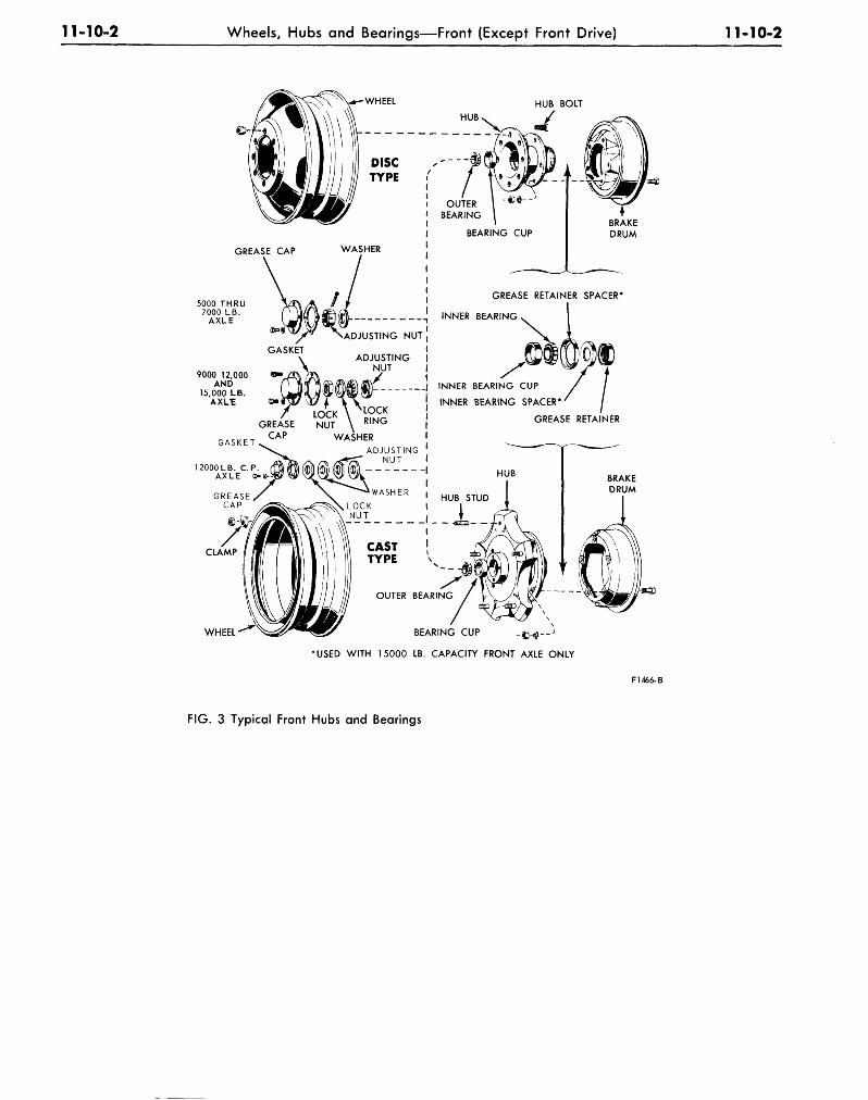
11-10-2 Wheels, Hubs and Bearings—Front (Except Front Drive) 11-10-2
HUB BOLT
GREASE CAP WASHER
5000 THRU7000 LB.
AXLE
9000 12,000AND
15,000 LB.AXLE <D»
»4f' / * NADJUSTING NUT
GASKET\ ADJUSTING
- A V NUT
GASKET
1
GREASE NUT \ R I N G
CAP WASHER
12000LB. C.P.AXLE
GREASE RETAINER SPACER*
INNER BEARING
INNER BEARING CUP
INNER BEARING SPACER*
GREASE RETAINER
CLAMP
WHEEL BEARING CUP -%^--J
•USED WITH 15000 LB. CAPACITY FRONT AXLE ONLY
F1466-B
FIG. 3 Typical Front Hubs and Bearings
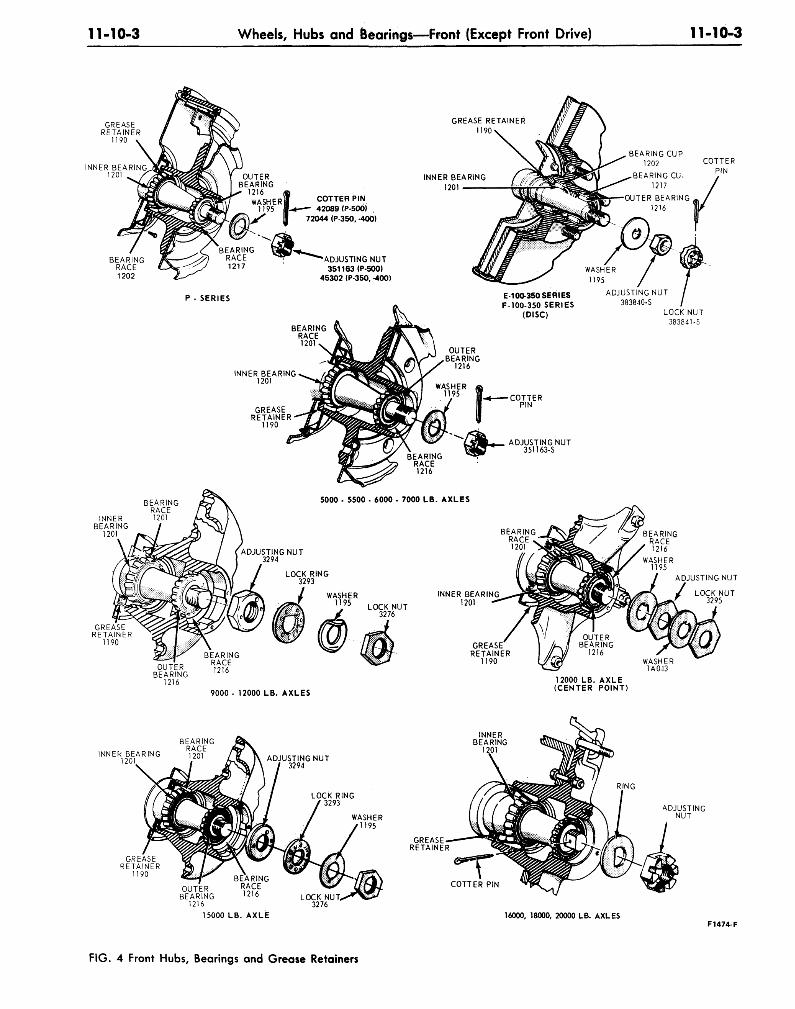
11-10-3 Wheels, Hubs and Bearings—Front (Except Front Drive) 11-10-3
INNER BEARING1201
GREASE RETAINER1190
INNER BEARING1201
COTTER PIN42089 (P-500)
72044 (P-350. -400)
ADJUSTING NUT351163 (P-500)
45302 (P-350, -400)
BEARING CUP1202
BEARING CU.1217
OUTER BEARING1216
P - SERIES E-10O-350 SERIESF-100-350 SERIES
(DISC)
BEARINGRACE1201
ADJUSTING NUT383840-5
LOCK NUT383841-S
INNER BEARING1201
BEARINGRACE
INNER 1201BEARING
1201
9000- 12000 LB. AXLES
12000 LB. AXLE(CENTER POINT)
BEARINGR ACF
INNER BEARING 1201
INNERBEARING
1ADJUSTING NUT
3294
LOCK RING3293
GREASERETAINER
1190 S) /XOUTER
BEARING1216
15000
\ IBEARING
RACE1216
LB. AXLE
LOCK NUT3276
COTTER PIN
16000, 18000, 20000 LB. AXLESF1474-F
FIG. 4 Front Hubs, Bearings and Grease Retainers
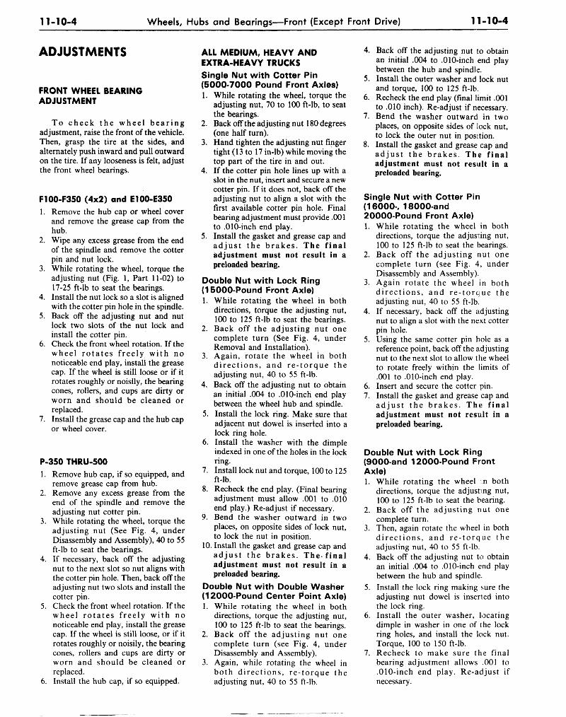
11-10-4 Wheels, Hubs and Bearings—Front (Except Front Drive) 11-10-4
ADJUSTMENTS
FRONT WHEEL BEARINGADJUSTMENT
To check the wheel bearingadjustment, raise the front of the vehicle.Then, grasp the tire at the sides, andalternately push inward and pull outwardon the tire. If any looseness is felt, adjustthe front wheel bearings.
F100-F350 (4x2) and E100-E3501. Remove the hub cap or wheel cover
and remove the grease cap from thehub.
2. Wipe any excess grease from the endof the spindle and remove the cotterpin and nut lock.
3. While rotating the wheel, torque theadjusting nut (Fig. 1, Part 11-02) to17-25 ft-lb to seat the bearings.
4. Install the nut lock so a slot is alignedwith the cotter pin hole in the spindle.
5. Back off the adjusting nut and nutlock two slots of the nut lock andinstall the cotter pin.
6. Check the front wheel rotation. If thewheel rotates freely with nonoticeable end play, install the greasecap. If the wheel is still loose or if itrotates roughly or noisily, the bearingcones, rollers, and cups are dirty orworn and should be cleaned orreplaced.
7. Install the grease cap and the hub capor wheel cover.
P-350 THRU-5001. Remove hub cap, if so equipped, and
remove grease cap from hub.2. Remove any excess grease from the
end of the spindle and remove theadjusting nut cotter pin.
3. While rotating the wheel, torque theadjusting nut (See Fig. 4, underDisassembly and Assembly), 40 to 55ft-lb to seat the bearings.
4. If necessary, back off the adjustingnut to the next slot so nut aligns withthe cotter pin hole. Then, back off theadjusting nut two slots and install thecotter pin.
5. Check the front wheel rotation. If thewheel rotates freely with nonoticeable end play, install the greasecap. If the wheel is still loose, or if itrotates roughly or noisily, the bearingcones, rollers and cups are dirty orworn and should be cleaned orreplaced.
6. Install the hub cap, if so equipped.
ALL MEDIUM, HEAVY ANDEXTRA-HEAVY TRUCKSSingle Nut with Cotter Pin(5000-7000 Pound Front Axles)1. While rotating the wheel, torque the
adjusting nut, 70 to 100 ft-lb, to seatthe bearings.
2. Back off the adjusting nut 180 degrees(one half turn).
3. Hand tighten the adjusting nut fingertight (13 to 17 in-lb) while moving thetop part of the tire in and out.
4. If the cotter pin hole lines up with aslot in the nut, insert and secure a newcotter pin. If it does not, back off theadjusting nut to align a slot with thefirst available cotter pin hole. Finalbearing adjustment must provide .001to .010-inch end play.
5. Install the gasket and grease cap andadjust the brakes. The finaladjustment must not result in apreloaded bearing.
Double Nut with Lock Ring(15000-Pound Front Axle)1. While rotating the wheel in both
directions, torque the adjusting nut,100 to 125 ft-lb to seat the bearings.
2. Back off the adjusting nut onecomplete turn (See Fig. 4, underRemoval and Installation).
3. Again, rotate the wheel in bothdirections, and re-torque theadjusting nut, 40 to 55 ft-lb.
4. Back off the adjusting nut to obtainan initial .004 to .010-inch end playbetween the wheel hub and spindle.
5. Install the lock ring. Make sure thatadjacent nut dowel is inserted into alock ring hole.
6. Install the washer with the dimpleindexed in one of the holes in the lockring.
7. Install lock nut and torque, 100 to 125ft-lb.
8. Recheck the end play. (Final bearingadjustment must allow .001 to .010end play.) Re-adjust if necessary.
9. Bend the washer outward in twoplaces, on opposite sides of lock nut,to lock the nut in position.
10. Install the gasket and grease cap andadjust the brakes. The finaladjustment must not result in apreloaded bearing.
Double Nut with Double Washer(12000-Pound Center Point Axle)1. While rotating the wheel in both
directions, torque the adjusting nut,100 to 125 ft-lb to seat the bearings.
2. Back off the adjusting nut onecomplete turn (see Fig. 4, underDisassembly and Assembly).
3. Again, while rotating the wheel inboth directions, re-torque theadjusting nut, 40 to 55 ft-lb.
4. Back off the adjusting nut to obtainan initial .004 to .010-inch end playbetween the hub and spindle.
5. Install the outer washer and lock nutand torque, 100 to 125 ft-lb.
6. Recheck the end play (final limit .001to .010 inch). Re-adjust if necessary.
7. Bend the washer outward in twoplaces, on opposite sides of lock nut,to lock the outer nut in position.
8. Install the gasket and grease cap andadjust the brakes. The finaladjustment must not result in apreloaded bearing.
Single Nut with Cotter Pin(16000-, 18000-and20000-Pound Front Axle)1. While rotating the wheel in both
directions, torque the adjusting nut,100 to 125 ft-lb to seat the bearings.
2. Back off the adjusting nut onecomplete turn (see Fig. 4, underDisassembly and Assembly).
3. Again rotate the wheel in bothdirections, and re-torque theadjusting nut, 40 to 55 ft-lb.
4. If necessary, back off the adjustingnut to align a slot with the next cotterpin hole.
5. Using the same cotter pin hole as areference point, back off the adjustingnut to the next slot to allow the wheelto rotate freely within the limits of.001 to .010-inch end play.
6. Insert and secure the cotter pin.7. Install the gasket and grease cap and
adjust the brakes. The finaladjustment must not result in apreloaded bearing.
Double Nut with Lock Ring(9000-and 12000-Pound FrontAxle)1. While rotating the wheel m both
directions, torque the adjusting nut,100 to 125 ft-lb to seat the bearing.
2. Back off the adjusting nut onecomplete turn.
3. Then, again rotate the wheel in bothdirections, and re-torque theadjusting nut, 40 to 55 ft-lb.
4. Back off the adjusting nut to obtainan initial .004 to .010-inch end playbetween the hub and spindle.
5. Install the lock ring making sure theadjusting nut dowel is inserted intothe lock ring.
6. Install the outer washer, locatingdimple in washer in one of the lockring holes, and install the lock nut.Torque, 100 to 150 ft-lb.
7. Recheck to make sure the finalbearing adjustment allows .001 to.010-inch end play. Re-adjust ifnecessary.
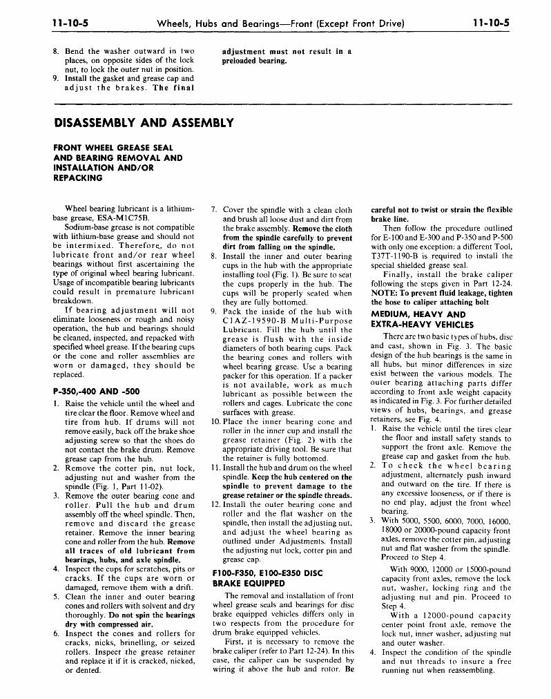
11-10-5 Wheels, Hubs and Bearings—Front (Except Front Drive) 11-10-5
8. Bend the washer outward in twoplaces, on opposite sides of the locknut, to lock the outer nut in position.
9. Install the gasket and grease cap andadjust the brakes. The final
adjustment must not result inpreloaded bearing.
DISASSEMBLY AND ASSEMBLY
FRONT WHEEL GREASE SEALAND BEARING REMOVAL ANDINSTALLATION AND/ORREPACKING
Wheel bearing lubricant is a lithium-base grease, ESA-M1C75B.
Sodium-base grease is not compatiblewith lithium-base grease and should notbe intermixed. Therefore., do notlubricate front and/or rear wheelbearings without first ascertaining thetype of original wheel bearing lubricant.Usage of incompatible bearing lubricantscould result in premature lubricantbreakdown.
If bearing adjustment will noteliminate looseness or rough and noisyoperation, the hub and bearings shouldbe cleaned, inspected, and repacked withspecified wheel grease. If the bearing cupsor the cone and roller assemblies areworn or damaged, they should bereplaced.
P-350,-400 AND -5001. Raise the vehicle until the wheel and
tire clear the floor. Remove wheel andtire from hub. If drums will notremove easily, back off the brake shoeadjusting screw so that the shoes donot contact the brake drum. Removegrease cap from the hub.
2. Remove the cotter pin, nut lock,adjusting nut and washer from thespindle (Fig. 1, Part 11-02).
3. Remove the outer bearing cone androller. Pull the hub and drumassembly off the wheel spindle. Then,remove and discard the greaseretainer. Remove the inner bearingcone and roller from the hub. Removeall traces of old lubricant frombearings, hubs, and axle spindle.
4. Inspect the cups for scratches, pits orcracks. If the cups are worn ordamaged, remove them with a drift.
5. Clean the inner and outer bearingcones and rollers with solvent and drythoroughly. Do not spin the bearingsdry with compressed air.
6. Inspect the cones and rollers forcracks, nicks, brinelling, or seizedrollers. Inspect the grease retainerand replace it if it is cracked, nicked,or dented.
7. Cover the spindle with a clean clothand brush all loose dust and dirt fromthe brake assembly. Remove the clothfrom the spindle carefully to preventdirt from falling on the spindle.
8. Install the inner and outer bearingcups in the hub with the appropriateinstalling tool (Fig. 1). Be sure to seatthe cups properly in the hub. Thecups will be properly seated whenthey are fully bottomed.
9. Pack the inside of the hub withC1AZ-1959O-B Multi-PurposeLubricant. Fill the hub until thegrease is flush with the insidediameters of both bearing cups. Packthe bearing cones and rollers withwheel bearing grease. Use a bearingpacker for this operation. If a packeris not available, work as muchlubricant as possible between therollers and cages. Lubricate the conesurfaces with grease.
10. Place the inner bearing cone androller in the inner cup and install thegrease retainer (Fig. 2) with theappropriate driving tool. Be sure thatthe retainer is fully bottomed.
11. Install the hub and drum on the wheelspindle. Keep the hub centered on thespindle to prevent damage to thegrease retainer or the spindle threads.
12. Install the outer bearing cone androller and the flat washer on thespindle, then install the adjusting nut,and adjust the wheel bearing asoutlined under Adjustments. Installthe adjusting nut lock, cotter pin andgrease cap.
F100-F350, E100-E350 DISCBRAKE EQUIPPED
The removal and installation of frontwheel grease seals and bearings for discbrake equipped vehicles differs only intwo respects from the procedure fordrum brake equipped vehicles.
First, it is necessary to remove thebrake caliper (refer to Part 12-24). In thiscase, the caliper can be suspended bywiring it above the hub and rotor. Be
careful not to twist or strain the flexiblebrake line.
Then follow the procedure outlinedfor E-100 and E-300 and P-350 and P-500with only one exception: a different Tool,T37T-1190-B is required to install thespecial shielded grease seal.
Finally, install the brake caliperfollowing the steps given in Part 12-24.NOTE: To prevent fluid leakage, tightenthe hose to caliper attaching bolt
MEDIUM, HEAVY ANDEXTRA-HEAVY VEHICLES
There are two basic types of hubs, discand cast, shown in Fig. 3. The basicdesign of the hub bearings is the same inall hubs, but minor differences in sizeexist between the various models. Theouter bearing attaching parts differaccording to front axle weight capacityas indicated in Fig. 3. For further detailedviews of hubs, bearings, and greaseretainers, see Fig. 4.1. Raise the vehicle until the tires clear
the floor and install safety stands tosupport the front axle. Remove thegrease cap and gasket from the hub.
2. To check the wheel bearingadjustment, alternately push inwardand outward on the tire. If there isany excessive looseness, or if there isno end play, adjust the front wheelbearing.
3. With 5000, 5500, 6000, 7000, 16000,18000 or 20000-pound capacity frontaxles, remove the cotter pin, adjustingnut and flat washer from the spindle.Proceed to Step 4.
With 9000, 12000 or 15000-poundcapacity front axles, remove the locknut, washer, locking ring and theadjusting nut and pin. Proceed toStep 4.
With a 12000-pound capacitycenter point front axle, remove thelock nut, inner washer, adjusting nutand outer washer.
4. Inspect the condition of the spindleand nut threads to insure a freerunning nut when reassembling.
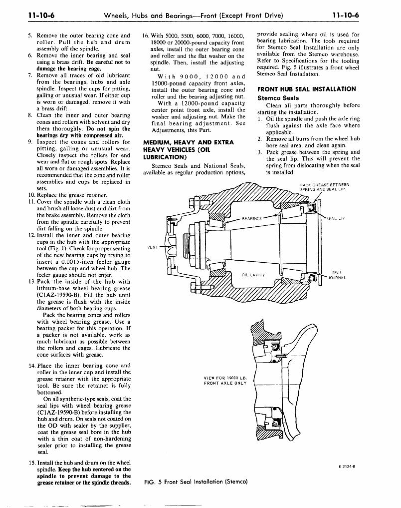
11-10-6 Wheels, Hubs and Bearings—Front (Except Front Drive) 11-10-6
5. Remove the outer bearing cone androller. Pull the hub and drumassembly off the spindle.
6. Remove the inner bearing and sealusing a brass drift. Be careful not todamage the bearing cage.
7. Remove all traces of old lubricantfrom the bearings, hubs and axlespindle. Inspect the cups for pitting,galling or unusual wear. If either cupis worn or damaged, remove it witha brass drift.
8. Clean the inner and outer bearingcones and rollers with solvent and drythem thoroughly. Do not spin thebearings dry with compressed air.
9. Inspect the cones and rollers forpitting, galling or unusual wear.Closely inspect the rollers for endwear and flat or rough spots. Replaceall worn or damaged assemblies. It isrecommended that the cone and rollerassemblies and cups be replaced insets.
10. Replace the grease retainer.11. Cover the spindle with a clean cloth
and brush all loose dust and dirt fromthe brake assembly. Remove the clothfrom the spindle carefully to preventdirt falling on the spindle.
12. Install the inner and outer bearingcups in the hub with the appropriatetool (Fig. 1). Check for proper seatingof the new bearing cups by trying toinsert a 0.0015-inch feeler gaugebetween the cup and wheel hub. Thefeeler gauge should not enter.
13. Pack the inside of the hub withlithium-base wheel bearing grease(C1AZ-19590-B). Fill the hub untilthe grease is flush with the insidediameters of both bearing cups.
Pack the bearing cones and rollerswith wheel bearing grease. Use abearing packer for this operation. Ifa packer is not available, work asmuch lubricant as possible betweenthe rollers and cages. Lubricate thecone surfaces with grease.
14. Place the inner bearing cone androller in the inner cup and install thegrease retainer with the appropriatetool. Be sure the retainer is fullybottomed.
On all synthetic-type seals, coat theseal lips with wheel bearing grease(C1AZ-19590-B) before installing thehub and drum. On seals not coated onthe OD with sealer by the supplier,coat the grease seal bore in the hubwith a thin coat of non-hardeningsealer prior to installing the greaseseal.
15. Install the hub and drum on the wheelspindle. Keep the hub centered on thespindle to prevent damage to thegrease retainer or the spindle threads.
16. With 5000, 5500, 6000, 7000, 16000,18000 or 20000-pound capacity frontaxles, install the outer bearing coneand roller and the flat washer on thespindle. Then, install the adjustingnut.
W i t h 9 0 0 0 , 1 2 0 0 0 a n d15000-pound capacity front axles,install the outer bearing cone androller and the bearing adjusting nut.
With a 12000-pound capacitycenter point front axle, install thewasher and adjusting nut. Make thefinal bearing adjustment. SeeAdjustments, this Part.
MEDIUM, HEAVY AND EXTRAHEAVY VEHICLES (OILLUBRICATION)
Stemco Seals and National Seals,available as regular production options,
provide sealing where oil is used forbearing lubrication. The tools requiredfor Stemco Seal Installation are onlyavailable from the Stemco warehouse.Refer to Specifications for the toolingrequired. Fig. 5 illustrates a front wheelStemco Seal Installation.
FRONT HUB SEAL INSTALLATION
Stemco SealsClean all parts thoroughly before
starting the installation.1. Oil the spindle and push the axle ring
flush against the axle face whereapplicable.
2. Remove all burrs from the wheel hubbore seal area, and clean again.
3. Pack grease between the spring andthe seal lip. This will prevent thespring from dislocating when the sealis installed.
PACK GREASE BETWEENSPRING AND SEAL LIP
"SEAL J P
VENT
SEALJOURNAL
VIEW FOR 15000 LB.FRONT AXLE ONLY
E 2124-B
FIG. 5 Front Seal Installation (Stemco)
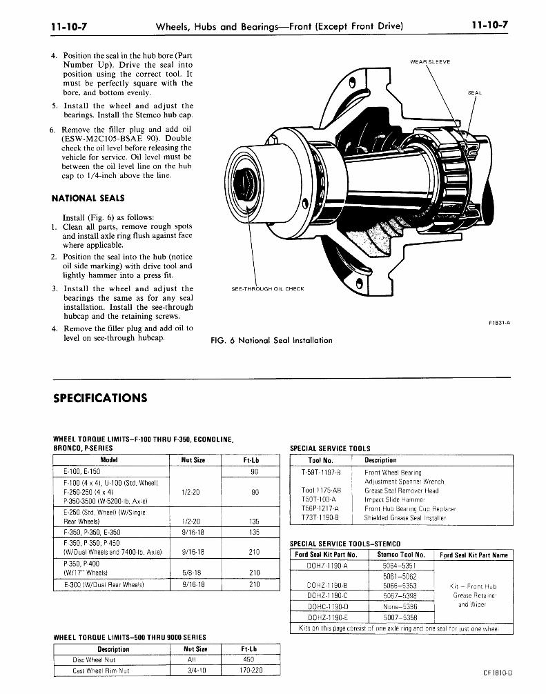
11-10-7 Wheels, Hubs and Bearings—Front (Except Front Drive) 11-10-7
4. Position the seal in the hub bore (PartNumber Up). Drive the seal intoposition using the correct tool. Itmust be perfectly square with thebore, and bottom evenly.
5. Install the wheel and adjust thebearings. Install the Stemco hub cap.
6. Remove the filler plug and add oil(ESW-M2C1O5-BSAE 90). Doublecheck the oil level before releasing thevehicle for service. Oil level must bebetween the oil level line on the hubcap to 1/4-inch above the line.
NATIONAL SEALS
Install (Fig. 6) as follows:1. Clean all parts, remove rough spots
and install axle ring flush against facewhere applicable.
2. Position the seal into the hub (noticeoil side marking) with drive tool andlightly hammer into a press fit.
3. Install the wheel and adjust thebearings the same as for any sealinstallation. Install the see-throughhubcap and the retaining screws.
4. Remove the filler plug and add oil tolevel on see-through hubcap.
WEAR SLEEVE
SEE-THROUGH OIL CHECK
FIG. 6 National Seal Installation
F1831-A
SPECIFICATIONS
WHEEL TORQUE LIMITS-F-100 THRU F-350, ECONOLINE,BRONCO, P SERIES
WHEEL TORQUE LIMITS-500 THRU 9000 SERIES
SPECIAL SERVICE TOOLS
Model
E-100, E-150
F-100 (4 x 4), U-100 (Std. Wheel)F-250-250 (4 x 4)P-350-3500 (W-5200-lb. Axle)
E-250 (Std. Wheel) (W/SingleRear Wheels)
F-350, P-350, E-350
F-350, P-350, P-450(W/Dual Wheels and 7400-lb. Axle)
P-350, P-400(W/17" Wheels)
E-300(W/Dual Rear Wheels)
Nut Size
1/2-20
1/2-20
9/16-18
9/16-18
5/8-18
9/16-18
Ft-Lb
90
90
135
135
210
210
210
Tool No.
T-59T-1197-B
Tool 1175-ABT50T-100-AT56P-1217-AT73T-1190-B
Description
Front Wheel BearingAdjustment Spanner WrenchGrease Seal Remover HeadImpact Slide HammerFront Hub Bearing Cup ReplacerShielded Grease Seal Installer
SPECIAL SERVICE TOOLS-STEMCO
Ford Seal Kit Part No.
DOHZ-1190-A
DOHZ-1190-B
DOHZ-1190-C
DOHC-1190-D
DOHZ-1190-E
Stemco Tool No.
5064-5351
5061-50625066-53535067-5398
None-5386
5007-5358
Ford Seal Kit Part Name
Kit - Front HubGrease Retainer
and Wiper
K i t s o n t h i s p a g e c o n s i s t o f o n e a x l e r i n g a n d o n e seal f o r j u s t o n e w h e e l
Description
Disc Wheel Nut
Cast Wheel Rim Nut
Nut Size
All
3/4-10
Ft-Lb
450
170-220 CF1810-D
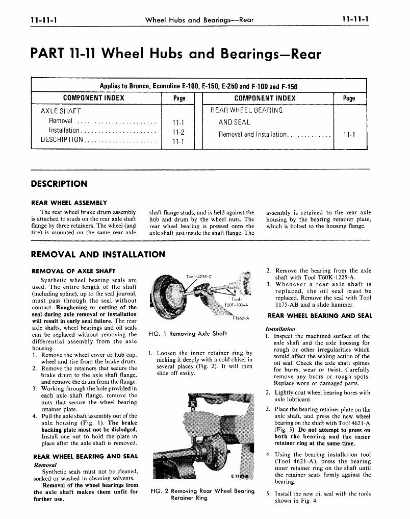
11-11-1 Wheel Hubs and Bearings—Rear 11-11-1
PART 11-11 Wheel Hubs and Bearings-Rear
Applies to Bronco, Econoline E-100, E-150, E-250 and F-100 and F 150
COMPONENT INDEX
AXLE SHAFT
Removal
Installation
DESCRIPTION
Page
11-1
11-2
11-1
COMPONENT INDEX
REAR WHEEL BEARING
AND SEAL
Removal and Installation
Page
11-1
DESCRIPTION
REAR WHEEL ASSEMBLYThe rear wheel brake drum assembly
is attached to studs on the rear axle shaftflange by three retainers. The wheel (andtire) is mounted on the same rear axle
shaft flange studs, and is held against thehub and drum by the wheel nuts. Therear wheel bearing is pressed onto theaxle shaft just inside the shaft flange. The
assembly is retained to the rear axlehousing by the bearing retainer plate,which is bolted to the housing flange.
REMOVAL AND INSTALLATION
REMOVAL OF AXLE SHAFTSynthetic wheel bearing seals are
used. The entire length of the shaft(including spline), up to the seal journal,must pass through the seal withoutcontact. Roughening or cutting of theseal during axle removal or installationwill result in early seal failure. The rearaxle shafts, wheel bearings and oil sealscan be replaced without removing thedifferential assembly from the axlehousing.1. Remove the wheel cover or hub cap,
wheel and tire from the brake drum.2. Remove the retainers that secure the
brake drum to the axle shaft flange,and remove the drum from the flange.
3. Working through the hole provided ineach axle shaft flange, remove thenuts that secure the wheel bearingretainer plate.
4. Pull the axle shaft assembly out of theaxle housing (Fig. 1). The brakebacking plate must not be dislodged.Install one nut to hold the plate inplace after the axle shaft is removed.
REAR WHEEL BEARING AND SEALRemoval
Synthetic seals must not be cleaned,soaked or washed in cleaning solvents.
Removal of the wheel bearings fromthe axle shaft makes them unfit forfurther use.
F1662-A
FIG. 1 Removing Axle Shaft
Loosen the inner retainer ring bynicking it,deeply with a cold chisel inseveral places (Fig. 2). It will thenslide off easily.
E 173141
FIG. 2 Removing Rear Wheel BearingRetainer Ring
2. Remove the bearing from the axleshaft with Tool T60K-1225-A.
3. Whenever a rear axle shaft isreplaced, the oil seal must bereplaced. Remove the seal with Tool1175-AB and a slide hammer.
REAR WHEEL BEARING AND SEAL
Installation1. Inspect the machined surface of the
axle shaft and the axle housing forrough or other irregularities whichwould affect the sealing action of theoil seal. Check the axle shaft splinesfor burrs, wear or twist. Carefullyremove any burrs or rough spots.Replace worn or damaged parts.
2. Lightly coat wheel bearing bores withaxle lubricant.
3. Place the bearing retainer plate on theaxle shaft, and press the new wheelbearing on the shaft with Tool 4621-A(Fig. 3). Do not attempt to press onboth the bearing and the innerretainer ring at the same time.
4. Using the bearing installation tool(Tool 4621-A), press the bearinginner retainer ring on the shaft untilthe retainer seats firmly against thebearing.
5. Install the new oil seal with the toolsshown in Fig. 4.
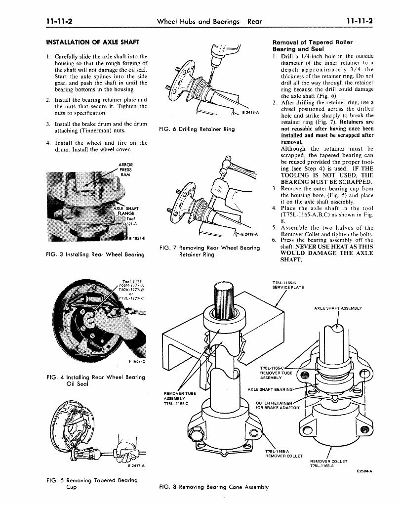
11-11-2 Wheel Hubs and Bearings—Rear 11-11-2
INSTALLATION OF AXLE SHAFT
1. Carefully slide the axle shaft into thehousing so that the rough forging ofthe shaft will not damage the oil seal.Start the axle splines into the sidegear, and push the shaft in until thebearing bottoms in the housing.
2. Install the bearing retainer plate andthe nuts that secure it. Tighten thenuts to specification.
3. Install the brake drum and the drumattaching (Tinnerman) nuts.
4. Install the wheel and tire on thedrum. Install the wheel cover.
E1921-B
E 2418-A
FIG. 6 Drilling Retainer Ring
E 2419-A
FIG.FIG. 3 Installing Rear Wheel Bearing
7 Removing Rear Wheel BearingRetainer Ring
Removal of Tapered RollerBearing and Seal1. Drill a 1/4-inch hole in the outside
diameter of the inner retainer to adepth approximately 3/4 thethickness of the retainer ring. Do notdrill all the way through the retainerring because the drill could damagethe axle shaft (Fig. 6).
2. After drilling the retainer ring, use achisel positioned across the drilledhole and strike sharply to break theretainer ring (Fig. 7). Retainers arenot reusable after having once beeninstalled and must be scrapped afterremoval.Although the retainer must bescrapped, the tapered bearing canbe reused provided the proper tool-ing (see Step 4) is used. IF THETOOLING IS NOT USED, THEBEARING MUST BE SCRAPPED.
3. Remove the outer bearing cup fromthe housing bore, (Fig. 5) and placeit on the axle shaft assembly.
4. Place the axle shaft in the tool(T75L-1165-A,B,C) as shown in Fig.8.
5. Assemble the two halves of theRemover Collet and tighten the bolts.
6. Press the bearing assembly off theshaft NEVER USE HEAT AS THISWOULD DAMAGE THE AXLESHAFT.
Tool 7 777T66N-17 77-A760 K- 7 777-8
or-I777-C
F1669-C
FIG. 4 Installing Rear Wheel BearingOil Seal
FIG. 5 Removing Tapered BearingCup
T75L-1165-BSERVICE PLATE
AXLE SHAFT ASSEMBLY
REMOVER TUBEASSEMBLYT75L-1165-C
REMOVER COLLETT75L-1165-A
E2584-A
FIG. 8 Removing Bearing Cone Assembly
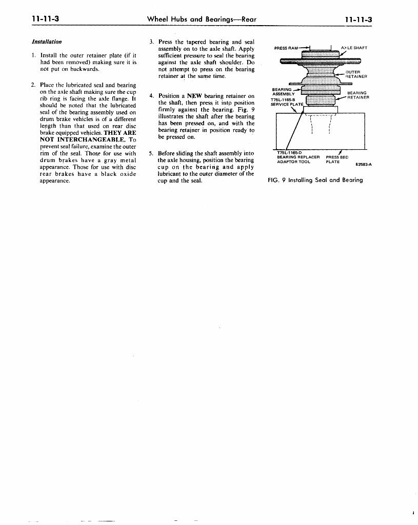
11-11-3 Wheel Hubs and Bearings—Rear 11-11-3
Installation
1. Install the outer retainer plate (if ithad been removed) making sure it isnot put on backwards.
2. Place the lubricated seal and bearingon the axle shaft making sure the cuprib ring is facing the axle flange. Itshould be noted that the lubricatedseal of the bearing assembly used ondrum brake vehicles is of a differentlength than that used on rear discbrake equipped vehicles. THEY ARENOT INTERCHANGEABLE. Toprevent seal failure, examine the outerrim of the seal. Those for use withdrum brakes have a gray metalappearance. Those for use with discrear brakes have a black oxideappearance.
3. Press the tapered bearing and sealassembly on to the axle shaft. Applysufficient pressure to seal the bearingagainst the axle shaft shoulder. Donpt attempt to press on the bearingretainer at the same time.
4. Position a NEW bearing retainer onthe shaft, then press it intp positionfirmly against the bearing. Fig. 9illustrates the shaft after the bearinghas been pressed on, and with thebearing retainer in position reacjy tobe pressed on.
5. Before sliding the shaft assembly intothe axle housing, position the bearingcup on the bear ing and applylubricant to the outer diameter of thecup and the seal.
PRESS RAM
BEARING
OUTERDETAINER
T75L-1165-D /BEARING REPLACER PRESS BEDADAPTOR TOOL PLATE
E2583-A
FIG. 9 Installing Seal and Bearing
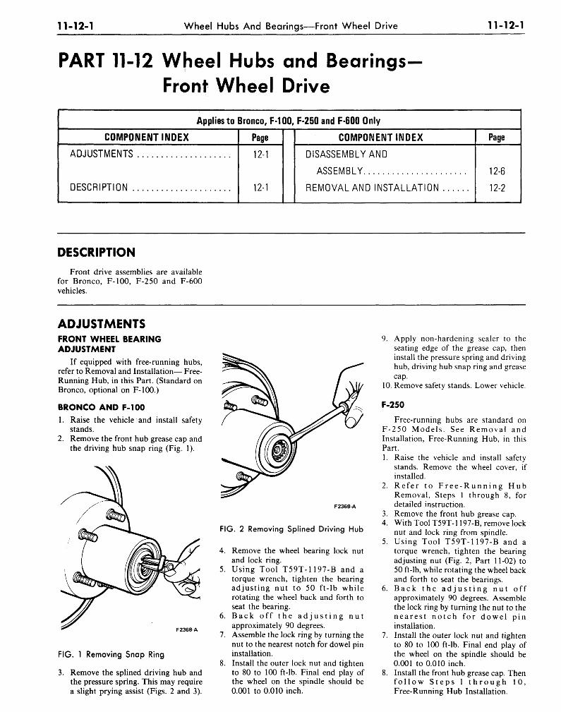
11-12-1 Wheel Hubs And Bearings—Front Wheel Drive 11-12-1
PART 11-12 Wheel Hubs and BearingsFront Wheel Drive
Applies to Bronco, MOO, F-250 and F-600 Only
COMPONENT INDEX
ADJUSTMENTS
DESCRIPTION
Page
12-1
12-1
COMPONENT INDEX
DISASSEMBLY AND
ASSEMBLY
REMOVAL AND INSTALLATION
Page
12-6
12-2
DESCRIPTIONFront drive assemblies are available
for Bronco, F-100, F-250 and F-600vehicles.
ADJUSTMENTSFRONT WHEEL BEARINGADJUSTMENT
If equipped with free-running hubs,refer to Removal and Installation— Free-Running Hub, in this Part. (Standard onBronco, optional on F-100.)
BRONCO AND F-100
1. Raise the vehicle and install safetystands.
2. Remove the front hub grease cap andthe driving hub snap ring (Fig. 1).
F2368-A
FIG. 1 Removing Snap Ring
3. Remove the splined driving hub andthe pressure spring. This may requirea slight prying assist (Figs. 2 and 3).
F2369-A
FIG. 2 Removing Splined Driving Hub
4. Remove the wheel bearing lock nutand lock ring.
5. Using Tool T59T-1197-B and atorque wrench, tighten the bearingadjusting nut to 50 ft-lb whilerotating the wheel back and forth toseat the bearing.
6. B a c k off t h e a d j u s t i n g n u tapproximately 90 degrees.
7. Assemble the lock ring by turning thenut to the nearest notch for dowel pininstallation.
8. Install the outer lock nut and tightento 80 to 100 ft-lb. Final end play ofthe wheel on the spindle should be0.001 to 0.010 inch.
9. Apply non-hardening sealer to theseating edge of the grease cap, theninstall the pressure spring and drivinghub, driving hub snap ring and greasecap.
10. Remove safety stands. Lower vehicle.
F-250
Free-running hubs are standard onF-250 Models . See Removal andInstallation, Free-Running Hub, in thisPart.1. Raise the vehicle and install safety
stands. Remove the wheel cover, ifinstalled.
2. Refe r to F r e e - R u n n i n g HubRemoval, Steps 1 through 8, fordetailed instruction.
3. Remove the front hub grease cap.4. With Tool T59T-1197-B, remove lock
nut and lock ring from spindle.5. Using Tool T59T-1197-B and a
torque wrench, tighten the bearingadjusting nut (Fig. 2, Part 11-02) to50 ft-lb, while rotating the wheel backand forth to seat the bearings.
6. Back t h e a d j u s t i n g n u t offapproximately 90 degrees. Assemblethe lock ring by turning the nut to then e a r e s t n o t c h for dowel pininstallation.
7. Install the outer lock nut and tightento 80 to 100 ft-lb. Final end play ofthe wheel on the spindle should be0.001 to 0.010 inch.
8. Install the front hub grease cap. Thenf o l l o w S t e p s 1 t h r o u g h 10,Free-Running Hub Installation.
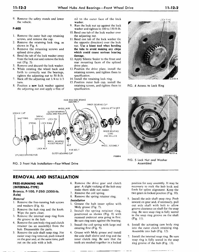
11-12-2 Wheel Hubs And Bearings—Front Wheel Drive 11-12-2
9. Remove the safety stands and lowerthe vehicle.
F-600
1. Remove the outer hub cap retainingscrews, and remove the cap.
2. Remove the retaining lock ring, asshown in Fig. 4.
3. Remove the retaining screws andsplined drive plate.
4. Bend the tab of the lock washer awayfrom the lock nut and remove the locknut (Fig. 5).
5. Remove and discard the lock washer.6. While rotating the wheel back and
forth to correctly seat the bearings,tighten the adjusting nut to 50 ft-lb.
7. Back off the adjusting nut 1/4 to 1/3turn.
8. Position a new lock washer againstthe adjusting nut and apply a film of
oil to the outer face of the lockwasher.
9. Run the lock nut up against the lockwasher and tighten to 100 to 150 ft-lb.
10. Bend one tab of the lock washer overthe adjusting nut.
11. Bend one tab of the lock washer (inthe opposite direction) over the locknut. Use a blunt tool when bendingthe tabs to avoid making any chipswhich could cause serious bearingdamage.
12. Apply Silastic Sealer to the front andrear mounting faces of the splineddrive plate.
13. Position the drive plate, install theretaining screws, and tighten them tospecification.
14. Install the retaining lock ring.15. Position outer hub cap, install the
retaining screws, and tighten them tospecification.
LOCK RING
i I in
FIG. 4 Access to Lock Ring
LOC.KW.ASH£f
HUB AND DISC BRAKEASSEMBLY
INNER BEARING CUP
GREASE RETAINER
SPLINED DRIVING HUB
NUT
HUB BOLT
OUTER BEARING CUP
WHEEL ASSEMBLY
F1300 EE2131-A
FIG. 3 Front Hub Installation—Four-Wheel DriveFIG. 5 Lock Nut and Washer
Assembled
REMOVAL AND INSTALLATIONFREE-RUNNING HUB(INTERNAL-TYPE)Bronco, F-100, F-250 (3300-lb.Axle)Removal1. Remove the free-running hub screws
and washers (Fig. 6).2. Remove the hub ring and the knob.
Wipe the parts clean.3. Remove the internal snap ring from
the groove in the hub.4. Remove the cam body ring and clutch
retainer (as an assembly) from thehub. Disassemble the parts.
5. Remove the axle shaft snap ring. Foreasier snap ring removal, push inwardon the gear and, at the same time, pullout on the axle with a bolt.
6.
7.
Remove the drive gear and clutchgear. A slight rocking of the hub maymake them slide out easier.Remove the coil spring.
8. Remove the spring retainer ring.Installation1. Grease the hub inner spline with
Moly grease (Fig. 7).2. Install the spring retainer ring,
positioned as shown (Fig. 8) withrecessed undercut area going in first.Be sure ring seats against the bearing.
3. Install the coil spring with large endentering first (Fig. 9).
4. Grease with Moly grease and installthe axle shaft sleeve and ring and theinner clutch ring. Be sure that theteeth are meshed together in a locked
6.
7.
position for easy assembly. It may benecessary to rock the hub back andforth for spline alignment. Keep thetwo gears in locked position (Fig. 10).
Install the axle shaft snap ring. Pushinward on gear and, if necessary, pullout axle shaft with bolt to allowgroove clearance on shaft for t he snapring. Be sure snap ring is fully seatedin the snap ring groove on the shaft(Fig. 11).
Install the actuating cam body ringinto the outer clutch retaining ring.Assemble into hub (Fig. 12).
Install the internal snap ring. Be suresnap ring is fully seated in the snapring groove of the hub (Fig. 13).
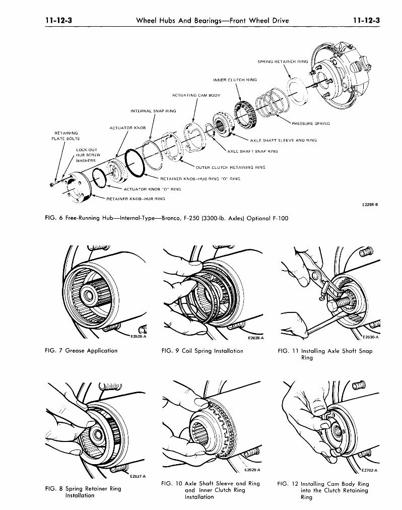
11-12-3 Wheel Hubs And Bearings—Front Wheel Drive 11-12-3
RETAINING
PLATE BOLTS / r ^«H./T L\\ WT \\ \ I t ^ AXLE SHAFT SLEEVE AND RING
AXLE SHAFT SNAP RING
OUTER CLUTCH RETAINING RING
RETAINER KNOB-HUB RING "O" RING
ACTUATOR KNOB "O" RING
RETAINER KNOB-HUB RING
FIG. 6 Free-Running Hub—Internal-Type—Bronco, F-250 (3300-lb. Axles) Optional F-100
E2298 B
E2626-A E2628 A
FIG. 7 Grease Application FIG. 9 Coil Spring Installation
E2630-A
FIG. 11 Installing Axle Shaft SnapRing
E2629 A
E2627 A
FIG. 8 Spring Retainer RingInstallation
FIG. 10 Axle Shaft Sleeve and Ringand Inner Clutch RingInstallation
E2702A
FIG. 12 Installing Cam Body Ringinto the Clutch RetainingRing
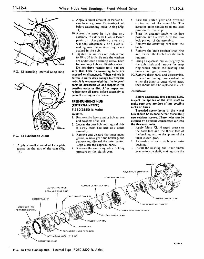
11-12-4 Wheel Hubs And Bearings—Front Wheel Drive 11-12-4
E2703-A
FIG. 13 Installing Internal Snap Ring
E2704-A
FIG. 14 Lubrication Areas
8. Apply a small amount of Lubriplategrease on the ears of the cam (Fig.14).
9. Apply a small amount of Parker O-ring lube in groove of actuating knobbefore assembling outer O-ring (Fig.14).
10. Assemble knob in hub ring andassemble to axle with knob in lockedposition. Assemble screws andwashers alternately and evenly,making sure the retainer ring is notcocked in the hub.
11. Tighten the six lock-out hub screwsto 30 to 35 in-lb. Be sure the washersare under each retaining screw. Eachfree-running hub will fit either wheel.Do not drive vehicle until you are
sure that both free-running hubs areengaged or disengaged. When vehicle isdriven in water deep enough to cover thehubs, it is recommended that the internalparts be disassembled and inspected forpossible water or dirt. After inspection,re-lubricate all parts before assembly toprevent rusting or corrosion.
FREE-RUNNING HUB(EXTERNAL-TYPE)F-250(3550-lb Axle)Removal1. Remove the free-running hub screws
and washers (Fig. 15).2. Loosen the gear hub housing and slide
it away from the hub and drumassembly.
3. Remove and discard the inner metalgasket, remove gear hub housing, andremove and discard the outer gasket.Wipe clean the exposed parts.
4. Remove the snap ring while holdingpressure on the clutch gear.
5. Ease the clutch gear and pressurespring out of the assembly. Theactuator knob should be in the lockposition for this step.
6. Turn the actuator knob to the freeposition. With a drift, drive the camlock pin out of the assembly.
7. Remove the actuating cam from theknob.
8. Remove the knob retainer snap ringand remove the knob from the knobretainer.
9. Using a capscrew, pull out slightly onthe axle shaft and remove the snapring which retains the bushing andinner clutch gear assembly.
10. Remove these parts and disassemble.If wear or damage are evident oneither the inner or outer clutch gear,they should both be replaced as a set.
Installation
Before assembling free-running hubs,inspect the splines of the axle shaft tomake sure they are free of any possiblenicks or burrs.
Threaded screw holes in the wheelhub should be cleaned before assemblingnew retainer screws. These holes can becleaned by directing compressed air intothe threaded holes.1. Apply Moly XL hi-speed grease to
the back face and the thrusi: face ofthe bushing, also to the splines of theinner clutch gear.
2. Assemble inner clutch gear intobushing.
3. Install the bushing and inner clutchgear onto axle shaft, making sure the
BUSHING
AXLE SHAFT SNAP RING
IGEAR HUB HOUSING
ACTUATING KNOB
RETAINER SNAP RING
CLUTCH GEAR SNAP RING
DISHED WASHER
LOCK-OUT HUB
RETAINER SCREWS
INNER CLUTCH GEAR
INNER (METAL) GASKET
OUTER RETAINER GASKET
OUTER CLUTCH GEAR
PRESSURE SPRING
ACTUATING CAM
ACTUATING KNOB RETAINER
ACTUATING KNOB "O" RING
ACTUATING KNOBE2306-B
FIG. 15 Free-Running Hob—External-Type (F-250-3500 Ib. Axles)
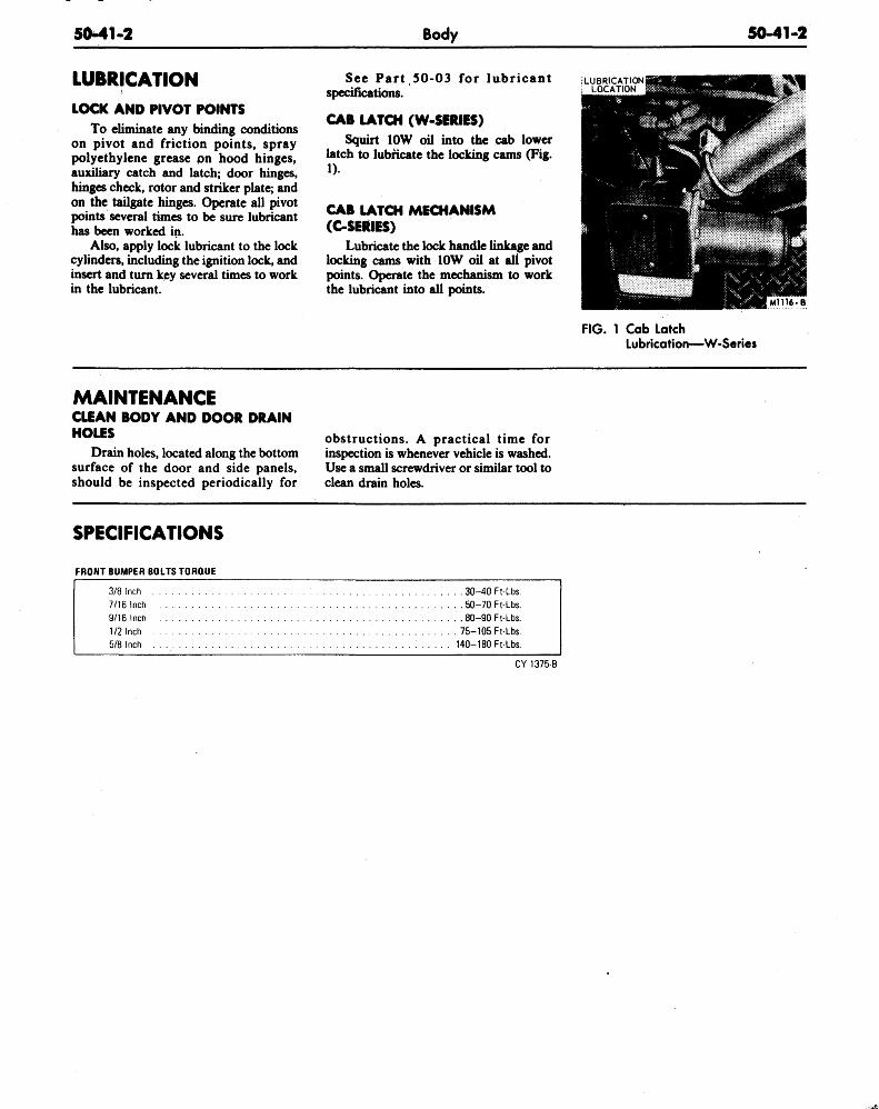
50-41-2 Body 50-41-2
LUBRICATIONLOCK AND PIVOT POINTS
To eliminate any binding conditionson pivot and friction points, spraypolyethylene grease pn hood hinges,auxiliary catch and latch; door hinges,hinges check, rotor and striker plate; andon the tailgate hinges. Operate all pivotpoints several times to be sure lubricanthas been worked in.
Also, apply lock lubricant to the lockcylinders, including the ignition lock, andinsert and turn key several times to workin the lubricant.
See Part 50-03 for lubricantspecifications.
CAB LATCH (W-SERIES)Squirt 10W oil into the cab lower
latch to lubricate the locking cams (Fig.1).
CAB LATCH MECHANISM(C-SEftlES)
Lubricate the lock handle linkage andlocking cams with 10W oil at all pivotpoints. Operate the mechanism to workthe lubricant into all points.
iLUBRICATIONLOCATION
FIG. 1 Cab LatchLubrication—W-Series
MAINTENANCECLEAN BODY AND DOOR DRAINHOLES
Drain holes, located along the bottomsurface of the door and side panels,should be inspected periodically for
obstructions. A practical time forinspection is whenever vehicle is washed.Use a small screwdriver or similar tool toclean drain holes.
SPECIFICATIONS
FRONT BUMPER BOLTS TORQUE
3/8 Inch
7/16 inch
9/16 Inch
1/2 Inch
5/8 Inch
. . 30-40 Ft-Lbs.
. . 50-70 Ft-Lbs.
. . 80-90 Ft-Lbs.
. 75-105 Ft-Lbs.
140-180 Ft-Lbs.
CY 1375-8