Embed Size (px)
Citation preview

DEMOLITION HAMMERModel 93853
SET up AND OpERATINg INSTRucTIONS
Visit our website at: http://www.harborfreight.com
Read this material before using this product. Failure to do so can result in serious injury. SAVE THIS MANuAL.
Copyright© 2006 by Harbor Freight Tools®. All rights reserved. No portion of this manual or any artwork
contained herein may be reproduced in any shape or form without the express written consent of Harbor
Freight Tools. Diagrams within this manual may not be drawn proportionally. Due to continuing improve-
ments, actual product may differ slightly from the product described herein. Tools required for assembly
and service may not be included.
For technical questions or replacement parts, please call 1-800-444-3353.Revised Manual 10d
SKU 93853 For technical questions, please call 1-800-444-3353 PAGE 2
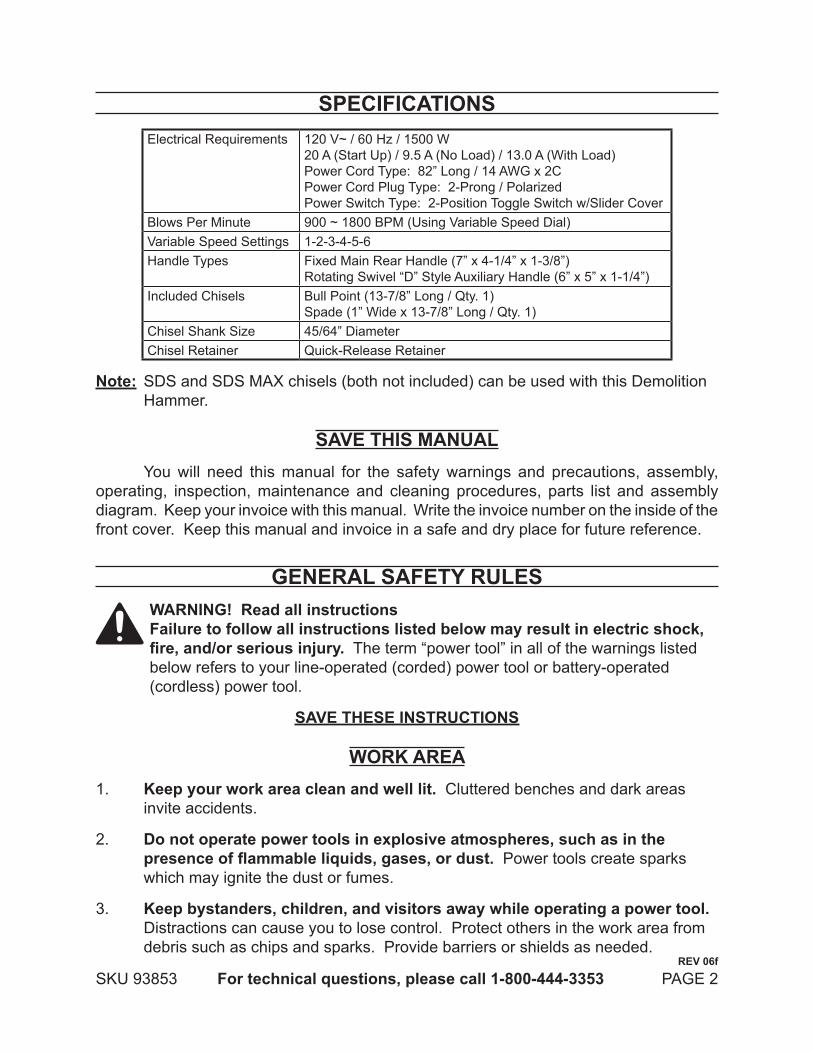
SpEcIFIcATIONSElectrical Requirements 120 V~ / 60 Hz / 1500 W
20 A (Start Up) / 9.5 A (No Load) / 13.0 A (With Load)Power Cord Type: 82” Long / 14 AWG x 2CPower Cord Plug Type: 2-Prong / PolarizedPower Switch Type: 2-Position Toggle Switch w/Slider Cover
Blows Per Minute 900 ~ 1800 BPM (Using Variable Speed Dial)Variable Speed Settings 1-2-3-4-5-6Handle Types Fixed Main Rear Handle (7” x 4-1/4” x 1-3/8”)
Rotating Swivel “D” Style Auxiliary Handle (6” x 5” x 1-1/4”)Included Chisels Bull Point (13-7/8” Long / Qty. 1)
Spade (1” Wide x 13-7/8” Long / Qty. 1)Chisel Shank Size 45/64” DiameterChisel Retainer Quick-Release Retainer
Note: SDS and SDS MAX chisels (both not included) can be used with this Demolition Hammer.
SAVE THIS MANuALYou will need this manual for the safety warnings and precautions, assembly,
operating, inspection, maintenance and cleaning procedures, parts list and assembly diagram. Keep your invoice with this manual. Write the invoice number on the inside of the front cover. Keep this manual and invoice in a safe and dry place for future reference.
gENERAL SAFETY RuLES WARNINg! Read all instructions Failure to follow all instructions listed below may result in electric shock, fire, and/or serious injury. The term “power tool” in all of the warnings listed below refers to your line-operated (corded) power tool or battery-operated (cordless) power tool.
SAVE THESE INSTRucTIONS
WORK AREAKeep your work area clean and well lit.1. Cluttered benches and dark areas invite accidents.
Do not operate power tools in explosive atmospheres, such as in the 2. presence of flammable liquids, gases, or dust. Power tools create sparks which may ignite the dust or fumes.
Keep bystanders, children, and visitors away while operating a power tool. 3. Distractions can cause you to lose control. Protect others in the work area from debris such as chips and sparks. Provide barriers or shields as needed.
REV 06f

SKU 93853 For technical questions, please call 1-800-444-3353 PAGE 3
ELEcTRIcAL SAFETYgrounded tools must be plugged into an outlet properly installed and 1. grounded in accordance with all codes and ordinances. Never remove the grounding prong or modify the plug in any way. Do not use any adapter plugs. Check with a qualified electrician if you are in doubt as to whether the outlet is properly grounded. If the tools should electrically malfunction or break down, grounding provides a low resistance path to carry electricity away from the user.
Double insulated tools are equipped with a polarized plug (one blade is 2. wider than the other). This plug will fit in a polarized outlet only one way. If the plug does not fit fully in the outlet, reverse the plug. If it still does not fit, contact a qualified electrician to install a polarized outlet. Do not change the plug in any way. Double insulation eliminates the need for the three wire grounded power cord and grounded power supply system.
Avoid body contact with grounded surfaces such as pipes, radiators, 3. ranges, and refrigerators. There is an increased risk of electric shock if your body is grounded.
Do not expose power tools to rain or wet conditions. 4. Water entering a power tool will increase the risk of electric shock.
Do not abuse the power cord.5. Never use the power cord to carry the tools or pull the plug from an outlet. Keep the power cord away from heat, oil, sharp edges, or moving parts. Replace damaged power cords immediately. Damaged Power Cords increase the risk of electric shock.
When operating a power tool outside, use an outdoor extension cord 6. marked “W-A” or “W”. These extension cords are rated for outdoor use, and reduce the risk of electric shock.
pERSONAL SAFETY Stay alert. Watch what you are doing, and use common sense when 1. operating a power tool. Do not use a power tool while tired or under the influence of drugs, alcohol, or medication. A moment of inattention while operating power tools may result in serious personal injury.
Dress properly. Do not wear loose clothing or jewelry. contain long 2. hair. Keep your hair, clothing, and gloves away from moving parts. Loose clothes, jewelry, or long hair can be caught in moving parts.
Avoid accidental starting.3. Be sure the power Switch is off before plugging in. Plugging in power tools with the Power Switch on invites accidents.
SKU 93853 For technical questions, please call 1-800-444-3353 PAGE 4
Remove adjusting keys or wrenches before turning the power tool on. 4. A wrench or a key that is left attached to a rotating part of the power tool may result in personal injury.
Do not overreach. Keep proper footing and balance at all times. 5. Proper footing and balance enables better control of the power tool in unexpected situations.
use safety equipment. Always wear eye protection. 6. Dust mask, non-skid safety shoes, hard hat, or hearing protection must be used for appropriate conditions.
TOOL uSE AND cAREuse clamps (not included) or other practical ways to secure and support 1. the workpiece to a stable platform. Holding the work by hand or against your body is unstable and may lead to loss of control.
Do not force the tool. use the correct tool for your application. 2. The correct tool will do the job better and safer at the rate for which it is designed.
Do not use the power tool if the power Switch does not turn it on or off. 3. Any tool that cannot be controlled with the Power Switch is dangerous and must be replaced.
Disconnect the power cord plug from the power source before making any 4. adjustments, changing accessories, or storing the tool. Such preventive safety measures reduce the risk of starting the tool accidentally.
Store idle tools out of reach of children and other untrained persons. 5. Tools are dangerous in the hands of untrained users.
Maintain tools with care. Keep cutting tools sharp and clean.6. Properly maintained tools with a sharp cutting edge are less likely to bind and are easier to control. Do not use a damaged tool. Tag damaged tools “Do not use” until repaired.
check for misalignment or binding of moving parts, breakage of parts, 7. and any other condition that may affect the tool’s operation. If damaged, have the tool serviced before using. Many accidents are caused by poorly maintained tools.
use only accessories that are recommended by the manufacturer for your 8. model. Accessories that may be suitable for one tool may become hazardous when used on another tool.

SKU 93853 For technical questions, please call 1-800-444-3353 PAGE 5
SERVIcETool service must be performed only by qualified repair personnel. 1. Service or maintenance performed by unqualified personnel could result in a risk of injury.
When servicing a tool, use only identical replacement parts. Follow 2. instructions in the “Inspection, Maintenance, And Cleaning” section of this manual. Use of unauthorized parts or failure to follow maintenance instructions may create a risk of electric shock or injury.
SpEcIFIc SAFETY RuLESMaintain labels and nameplates on the Demolition Hammer.1. These carry important information. If unreadable or missing, contact Harbor Freight Tools for a replacement.
Always wear ANSI-approved safety impact eye glasses and a full face 2. shield when using the Demolition Hammer. Also wear heavy-duty steel-toe boots, hearing protection, dust mask or respirator, and heavy duty work gloves. Using personal safety devices reduce the risk for injury.
Maintain a safe working environment. 3. Keep the work area well lit. Make sure there is adequate surrounding workspace. Always keep the work area free of obstructions, grease, oil, trash, and other debris. Do not use a power tool in areas near flammable chemicals, dusts, and vapors. Do not use this product in a damp or wet location.
Avoid unintentional starting. 4. Make sure you are prepared to begin work before turning on the Demolition Hammer.
Do not force the Demolition Hammer. 5. This tool will do the work better and safer at the speed and capacity for which it was designed.
Keep hands, fingers, and feet safely away from the cutting area.6.
Never leave the Demolition Hammer unattended when it is plugged into an 7. electrical outlet. Turn off the tool, and unplug it from its electrical outlet before leaving.
Before using the Demolition Hammer, check to make sure the chisel is 8. properly mounted in the Slider of the tool. Make sure the Chisel is sharp, and is not cracked or bent.
Industrial applications must follow OSHA guidelines.9.
Always hold the Demolition Hammer 10. with both hands by its insulated gripping surfaces; this offers protection against electrical shock, if the tool’s chisel contacts hidden wiring or its own power cord.

SKU 93853 For technical questions, please call 1-800-444-3353 PAGE 6
Do not drill or break into existing walls, floors, or other blind areas where 11. electrical wiring may exist. If this situation is unavoidable, disconnect all fuses or circuit breakers feeding the worksite.
use a metal detector to determine if there are gas or water pipes hidden 12. in the work area or call the local utility company for assistance before beginning the operation. Striking or cutting into a gas line will result in explosion. Water entering an electrical device may cause electrocution.
position yourself to avoid being caught between the Demolition Hammer 13. or Auxiliary Handle and walls or posts. Should the Chisel become bound or jammed in the work, the reaction of the tool could crush your hand or leg.
Do not strike the chisel with a handheld hammer or sledge hammer when 14. attempting to dislodge a bound or jammed chisel. Fragments of metal from the Chisel could dislodge and strike you or bystanders.
Never place the Demolition Hammer down until the Motor has come to a 15. complete stop.
The chisel may become hot after prolonged use. 16. When removing the Chisel from the tool, avoid contact with skin and use proper protective gloves when grasping the Chisel.
Do not force the chisel into the workpiece when cutting. 17. Apply moderate pressure, allowing the Chisel to cut without being forced.
Never attempt to remove material stuck in the moving parts of the 18. Demolition Hammer while it is plugged in and running.
Always unplug the Demolition Hammer from its electrical outlet before 19. performing and inspection, maintenance, or cleaning procedures.
Keep this product and all other tools and equipment away from children 20. and other unauthorized people. Do not allow spectators in the work area.
performance of this tool (if powered by line voltage) may vary depending 21. on variations in local line voltage. Extension cord usage may also affect tool performance.
use the right tool for the job. 22. Do not attempt to force a small tool to do the work of a larger industrial tool. There are certain applications for which this tool was designed. It will do the job better and more safely at the rate for which it was intended. Do not modify this tool, and do not use this tool for a purpose for which it is not intended.
WARNINg!23. Some dust created by power sanding, sawing, grinding, drilling, and other construction activities, contain chemicals known (to the State of California) to cause cancer, birth defects or other reproductive harm. Some examples of
SKU 93853 For technical questions, please call 1-800-444-3353 PAGE 7
these chemicals are: lead from lead-based paints, crystalline silica from bricks and cement or other masonry products, arsenic and chromium from chemically treated lumber. Your risk from these exposures varies, depending on how often you do this type of work. To reduce your exposure to these chemicals: work in a well ventilated area, and work with approved safety equipment, such as those dust masks that are specially designed to filter out microscopic particles. (California Health & Safety Code § 25249.5, et seq.)
People with pacemakers should consult their physician(s) before use. 24. Electromagnetic fields in close proximity to heart pacemaker could cause pacemaker interference or pacemaker failure. In addition, people with pacemakers should: • Avoid operating alone. • Don’t use with power switch locked on. • Properly maintain and inspect to avoid electrical shock. • Any power cord must be properly grounded. Ground Fault Circuit Interrupter (GFCI) should also be implemented – it prevents sustained electrical shock.
25. WARNINg! The warnings and cautions discussed in this manual cannot cover all possible conditions and situations that may occur. It must be understood by the operator that common sense and caution are factors which cannot be built into this product, but must be supplied by the operator.
SAVE THESE INSTRucTIONS

SKU 93853 For technical questions, please call 1-800-444-3353 PAGE 8
VIBRATION HAzARDThis tool vibrates during use. Repeated or long-term exposure to vibration may cause temporary or permanent physical injury, particularly to the hands, arms and shoulders. To reduce the risk of vibration-related injury:
Anyone using vibrating tools regularly or for an extended period should first 1. be examined by a doctor and then have regular medical check-ups to ensure medical problems are not being caused or worsened from use. Pregnant women or people who have impaired blood circulation to the hand, past hand injuries, nervous system disorders, diabetes, or Raynaud’s Disease should not use this tool. If you feel any medical or physical symptoms related to vibration (such as tingling, numbness, and white or blue fingers), seek medical advice as soon as possible.
Do not smoke during use. Nicotine reduces the blood supply to the hands and 2. fingers, increasing the risk of vibration-related injury.
Wear suitable gloves to reduce the vibration effects on the user.3.
Use tools with the lowest vibration when there is a choice between different 4. processes.
Include vibration-free periods each day of work.5.
Grip tool as lightly as possible (while still keeping safe control of it). Let the tool 6. do the work.
To reduce vibration, maintain the tool as explained in this manual. If any 7. abnormal vibration occurs, stop use immediately.
REV 07j
SKU 93853 For technical questions, please call 1-800-444-3353 PAGE 9
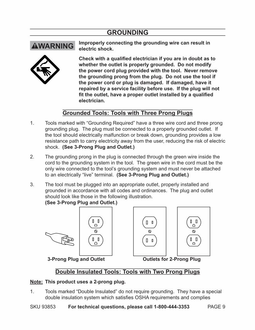
gROuNDINgImproperly connecting the grounding wire can result in electric shock.
Check with a qualified electrician if you are in doubt as to whether the outlet is properly grounded. Do not modify the power cord plug provided with the tool. Never remove the grounding prong from the plug. Do not use the tool if the power cord or plug is damaged. If damaged, have it repaired by a service facility before use. If the plug will not fit the outlet, have a proper outlet installed by a qualified electrician.
grounded Tools: Tools with Three prong plugsTools marked with “Grounding Required” have a three wire cord and three prong 1. grounding plug. The plug must be connected to a properly grounded outlet. If the tool should electrically malfunction or break down, grounding provides a low resistance path to carry electricity away from the user, reducing the risk of electric shock. (See 3-prong plug and Outlet.)
The grounding prong in the plug is connected through the green wire inside the 2. cord to the grounding system in the tool. The green wire in the cord must be the only wire connected to the tool’s grounding system and must never be attached to an electrically “live” terminal. (See 3-prong plug and Outlet.)
The tool must be plugged into an appropriate outlet, properly installed and 3. grounded in accordance with all codes and ordinances. The plug and outlet should look like those in the following illustration. (See 3-prong plug and Outlet.)
3-prong plug and Outlet Outlets for 2-prong plug
Double Insulated Tools: Tools with Two prong plugsNote: This product uses a 2-prong plug.
Tools marked “Double Insulated” do not require grounding. They have a special 1. double insulation system which satisfies OSHA requirements and complies
WARNINg
SKU 93853 For technical questions, please call 1-800-444-3353 PAGE 10
with the applicable standards of Underwriters Laboratories, Inc., the Canadian Standard Association, and the National Electrical Code. (See Outlets for 2-prong plug.)
Double insulated tools may be used in either of the 120 volt outlets shown in the 2. preceding illustration. (See Outlets for 2-prong plug.)
Extension cordsGrounded1. tools require a three wire extension cord. Double Insulated tools can use either a two or three wire extension cord.
As the distance from the supply outlet increases, you must use a heavier gauge 2. extension cord. Using extension cords with inadequately sized wire causes a serious drop in voltage, resulting in loss of power and possible tool damage. (See Table A.)
The smaller the gauge number of the wire, the greater the capacity of the cord. 3. For example, a 14 gauge cord can carry a higher current than a 16 gauge cord. (See Table A.)
When using more than one extension cord to make up the total length, make 4. sure each cord contains at least the minimum wire size required. (See Table A.)
If you are using one extension cord for more than one tool, add the nameplate5. amperes and use the sum to determine the required minimum cord size. (See Table A.)
If you are using an extension cord outdoors, make sure it is marked with the 6. suffix “W-A” (“W” in Canada) to indicate it is acceptable for outdoor use.
Make sure the extension cord is properly wired and in good electrical condition. 7. Always replace a damaged extension cord or have it repaired by a qualified electrician before using it.
Protect the extension cords from sharp objects, excessive heat, and damp or wet 8. areas.
SKU 93853 For technical questions, please call 1-800-444-3353 PAGE 11
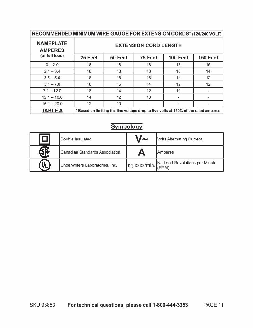
REcOMMENDED MINIMuM WIRE gAugE FOR EXTENSION cORDS* (120/240 VOLT)
NAMEpLATEAMpERES(at full load)
EXTENSION cORD LENgTH
25 Feet 50 Feet 75 Feet 100 Feet 150 Feet0 – 2.0 18 18 18 18 16
2.1 – 3.4 18 18 18 16 143.5 – 5.0 18 18 16 14 125.1 – 7.0 18 16 14 12 12
7.1 – 12.0 18 14 12 10 -12.1 – 16.0 14 12 10 - -16.1 – 20.0 12 10 - - -
TABLE A * Based on limiting the line voltage drop to five volts at 150% of the rated amperes.
Symbology
Double Insulated V~ Volts Alternating Current
Canadian Standards Association A Amperes
Underwriters Laboratories, Inc. n0 xxxx/min. No Load Revolutions per Minute (RPM)
SKU 93853 For technical questions, please call 1-800-444-3353 PAGE 12
uNpAcKINgWhen unpacking, check to make sure all the parts shown on the parts List on page
16 are included. If any parts are missing or broken, please call Harbor Freight Tools at the number shown on the cover of this manual as soon as possible.
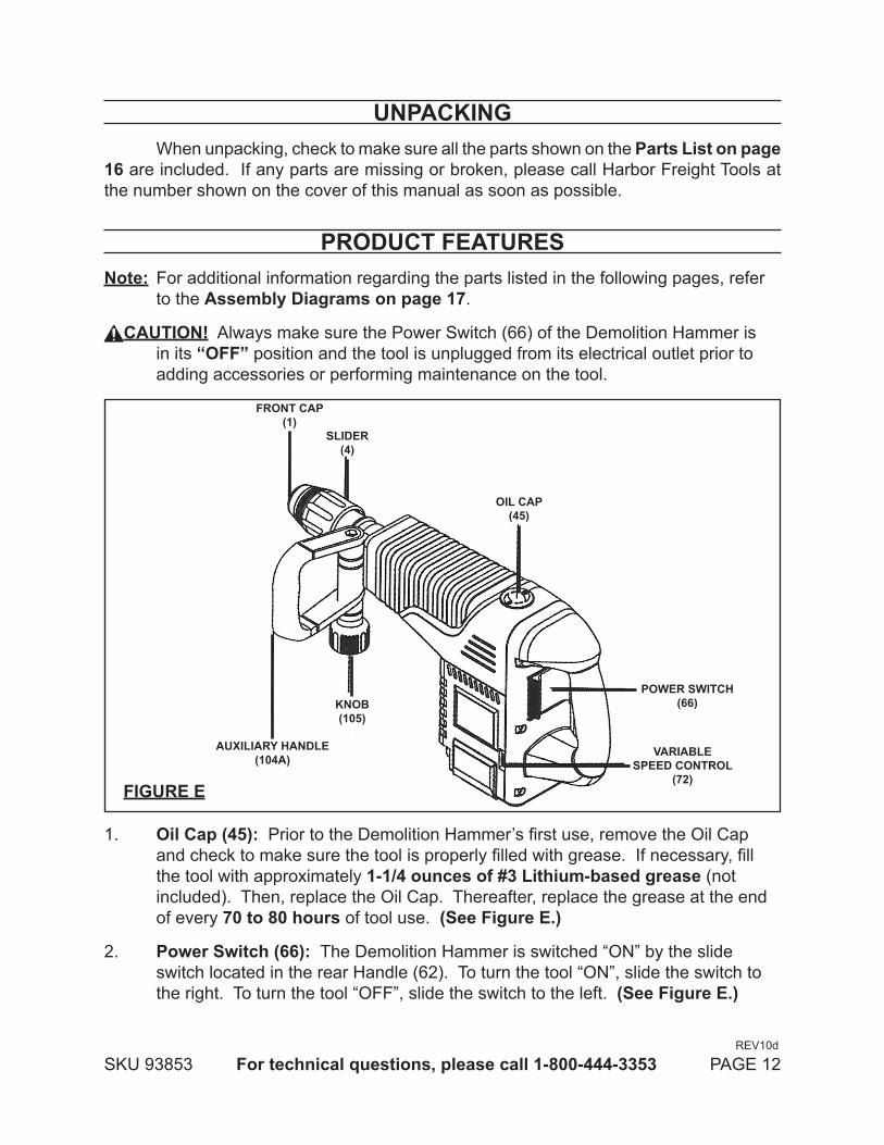
pRODucT FEATuRESNote: For additional information regarding the parts listed in the following pages, refer
to the Assembly Diagrams on page 17.
cAuTION! Always make sure the Power Switch (66) of the Demolition Hammer is in its “OFF” position and the tool is unplugged from its electrical outlet prior to adding accessories or performing maintenance on the tool.
OIL cAp(45)
SLIDER(4)
FRONT cAp(1)
KNOB(105)
AuXILIARY HANDLE(104A)
pOWER SWITcH(66)
VARIABLESpEED cONTROL
(72)FIguRE E
1. Oil cap (45): Prior to the Demolition Hammer’s first use, remove the Oil Cap and check to make sure the tool is properly filled with grease. If necessary, fill the tool with approximately 1-1/4 ounces of #3 Lithium-based grease (not included). Then, replace the Oil Cap. Thereafter, replace the grease at the end of every 70 to 80 hours of tool use. (See Figure E.)
power Switch (66): 2. The Demolition Hammer is switched “ON” by the slide switch located in the rear Handle (62). To turn the tool “ON”, slide the switch to the right. To turn the tool “OFF”, slide the switch to the left. (See Figure E.)
REV10d
SKU 93853 For technical questions, please call 1-800-444-3353 PAGE 13
Variable Speed control (72): 3. The Demolition Hammer is equipped with a Variable Speed Control Dial. The impact rate (BPM) and rotating speed (RPM) can be varied according to the type of work being performed by setting the Variable Speed Control Dial to the selected setting: 1-2-3-4-5-6 (“1” Being the lowest. “6” Being the highest.) The Variable Speed Control Dial may be adjusted while the Motor is running with the tool free from work, allowing the operator to adjust the impact rate and rotating speed according to the actual application. (See Figure E.)
Auxiliary Handle (104A) and Knob (105): 4. The Demolition Hammer must be supported with the Auxiliary Handle, which can be swiveled 360 degrees. To reposition and/or swivel the Auxiliary Handle, loosen the Knob. Move the Auxiliary Handle to the desired position along the barrel of the tool and firmly retighten the Knob. (See Figure E.)
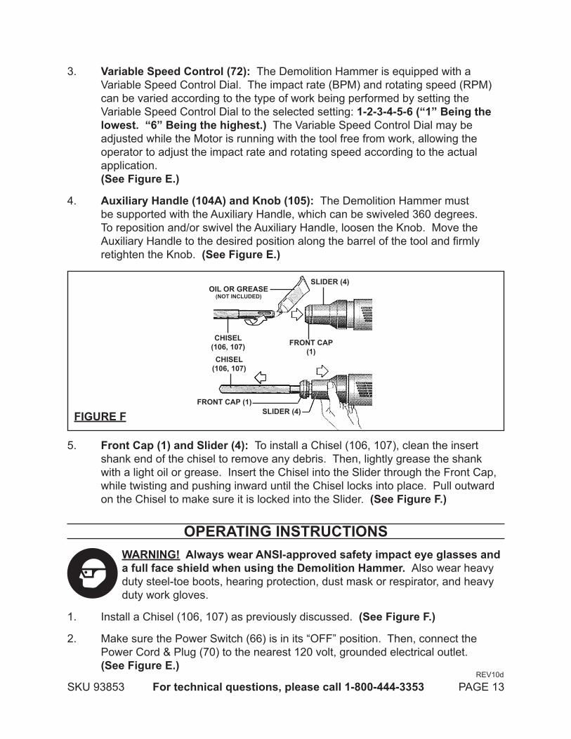
FIguRE F
SLIDER (4)
FRONT cAp(1)
OIL OR gREASE(NOT INcLuDED)
cHISEL(106, 107)
cHISEL(106, 107)
SLIDER (4)FRONT cAp (1)
5. Front cap (1) and Slider (4): To install a Chisel (106, 107), clean the insert shank end of the chisel to remove any debris. Then, lightly grease the shank with a light oil or grease. Insert the Chisel into the Slider through the Front Cap, while twisting and pushing inward until the Chisel locks into place. Pull outward on the Chisel to make sure it is locked into the Slider. (See Figure F.)
OpERATINg INSTRucTIONSWARNINg! Always wear ANSI-approved safety impact eye glasses and a full face shield when using the Demolition Hammer. Also wear heavy duty steel-toe boots, hearing protection, dust mask or respirator, and heavy duty work gloves.
Install a Chisel (106, 107) as previously discussed. 1. (See Figure F.)
Make sure the Power Switch (66) is in its “OFF” position. Then, connect the 2. Power Cord & Plug (70) to the nearest 120 volt, grounded electrical outlet. (See Figure E.)
REV10d
SKU 93853 For technical questions, please call 1-800-444-3353 PAGE 14
Grasp the Demolition Hammer firmly by its rear Handle (62) and Auxiliary Handle 3. (104A). Then, turn the Power Switch (66) to its “ON” position to begin work.
IMpORTANT: 4. This Demolition Hammer requires a short period of time to warm up. Depending on the room temperature, this time may vary from approximately 15 seconds (at 90 degrees Fahrenheit) to 2 minutes (at 32 degrees Fahrenheit). A new Hammer requires a break-in period before full performance is realized. This period may require up to 5 hours operation. (See Figure E.)
For the best penetration rates in concrete, run the Demolition Hammer with 5. a steady pressure but do not use excessive force as this will decrease the efficiency of the tool.
If necessary, adjust the Variable Speed Control Dial (72) to increase the tool’s 6. cutting efficiency. (See Figure E.)
When finished using the Demolition Hammer, turn the Power Switch (66) to its 7. “OFF” position. Then, unplug the tool from its electrical outlet. (See Figure E.)
Allow the Chisel (106, 107) to completely cool. Then, pull and hold the locking 8. Slider (4) backward and pull the Chisel forward. The Chisel should be cleaned after removing. (See Figure F.)
Make sure to store the Demolition Hammer in a clean, dry, safe location out of 9. reach of children and other unauthorized people.
INSpEcTION, MAINTENANcE, AND cLEANINgcAuTION! Always make sure the Power Switch (66) of the Demolition Hammer is
in its “OFF” position and the tool is unplugged from its electrical outlet prior to performing any inspection, maintenance, or cleaning.
Before each use,1. inspect the general condition of the Demolition Hammer. Check for loose screws, misalignment or binding of moving parts, cracked or broken parts, damaged electrical wiring, and any other condition that may affect its safe operation. If abnormal noise or vibration occurs, have the problem corrected before further use. Do not use damaged equipment.
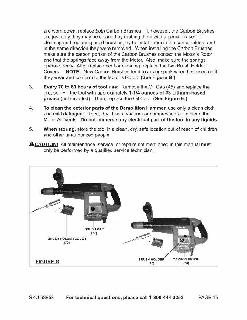
To replace the Motor carbon Brushes: 2. It may become necessary at sometime to replace or clean the two Carbon Brushes (76) when the Motor performance decreases, or stops working completely. The carbon Brushes are located on each side of the Motor casing (61). To replace the Carbon Brushes, remove the two Brush Holder Covers (79). Remove the Brush Caps (77). Then, remove the two Carbon Brushes from the two Brush Holders (75). If the Carbon Brushes
REV10d
SKU 93853 For technical questions, please call 1-800-444-3353 PAGE 15
are worn down, replace both Carbon Brushes. If, however, the Carbon Brushes are just dirty they may be cleaned by rubbing them with a pencil eraser. If cleaning and replacing used brushes, try to install them in the same holders and in the same direction they were removed. When installing the Carbon Brushes, make sure the carbon portion of the Carbon Brushes contact the Motor’s Rotor and that the springs face away from the Motor. Also, make sure the springs operate freely. After replacement or cleaning, replace the two Brush Holder Covers. NOTE: New Carbon Brushes tend to arc or spark when first used until they wear and conform to the Motor’s Rotor. (See Figure g.)
Every 70 to 80 hours of tool use: 3. Remove the Oil Cap (45) and replace the grease. Fill the tool with approximately 1-1/4 ounces of #3 Lithium-based grease (not included). Then, replace the Oil Cap. (See Figure E.)
To clean the exterior parts of the Demolition Hammer, 4. use only a clean cloth and mild detergent. Then, dry. Use a vacuum or compressed air to clean the Motor Air Vents. Do not immerse any electrical part of the tool in any liquids.
When storing, 5. store the tool in a clean, dry, safe location out of reach of children and other unauthorized people.
cAuTION! All maintenance, service, or repairs not mentioned in this manual must only be performed by a qualified service technician.
FIguRE g cARBON BRuSH(76)
BRuSH HOLDER(75)
BRuSH cAp(77)
BRuSH HOLDER cOVER(79)
SKU 93853 For technical questions, please call 1-800-444-3353 PAGE 16
TROuBLESHOOTINgproblem possible Solution
Chisel installs with difficulty. Make sure the Chisel shank, Front Cap, and Slider are free of debris and lightly oiled or greased. (See page 12.)
Tool does not run. Make sure the Power Switch is in its “ON” position. (See page 11.)1. Make sure the Power Cord & Plug is connected to a working 120 volt, 2. grounded electrical outlet. (See page 9.)Make sure the Power Cord & Plug is not damaged.3. Make sure the tool is filled with approximately 1-1/4 ounce of #3 4. Lithium-base grease. (See page 11.)Check the Motor Carbon Brushes for excessive wear and/or debris. 5. Replace or clean if necessary. (See page 14.)Have a qualified service technician service the tool. 6.
Tool does not stop. Make sure the Power Switch is in its “OFF” position. (See page 11.)1. Immediately disconnect the Power Cord & Plug from its electrical 2. outlet, and have a qualified service technician service the tool.
Poor cutting efficiency. Make sure the Chisel is clean and sharp.1. Adjust the Variable Speed Control Dial for the type of work being 2. done. (See page 12.)Apply moderate pressure only. Allow the tool to do the cutting without 3. being forced.Check the Motor Carbon Brushes for excessive wear and/or debris. 4. Replace or clean if necessary. (See page 14.)Have a qualified service technician service the tool.5.
Tool overheats and suddenly stops running.
Make sure the tool is filled with approximately 1-1/4 ounces of #3 1. Lithium-base grease. (See page 11.)Make sure the Motor Air Vents are clean and free of debris. (See 2. page 14.)Have a qualified service technician service the tool.3.
pLEASE READ THE FOLLOWINg cAREFuLLYTHE MANUFACTURER AND/OR DISTRIBUTOR HAS PROVIDED THE PARTS LIST AND ASSEMBLY DIAGRAM IN THIS MANUAL AS A REFERENCE TOOL ONLY. NEITHER THE MANUFACTURER OR DISTRIBUTOR MAKES ANY REPRESENTATION OR WARRANTY OF ANY KIND TO THE BUYER THAT HE OR SHE IS QUALIFIED TO REPLACE ANY PARTS OF THE PRODUCT. IN FACT, THE MANUFACTURER AND/OR DISTRIBUTOR EXPRESSLY STATES THAT ALL REPAIRS AND PARTS REPLACEMENTS SHOULD BE UNDERTAKEN BY CERTIFIED AND LICENSED TECHNICIANS, AND NOT BY THE BUYER. THE BUYER ASSUMES ALL RISKS AND LIABILITY ARISING OUT OF HIS OR HER REPAIRS TO THE ORIGINAL PRODUCT OR REPLACEMENT PARTS THERETO, OR ARISING OUT OF HIS OR HER INSTALLATION OF REPLACEMENT PARTS THERETO.

SKU 93853 For technical questions, please call 1-800-444-3353 PAGE 17
pARTS LIST
REV 06f, 08g, 10d
* cannot be ordered individually. Must be ordered as a complete Motor Assembly. Includes parts 33, 34, 35, 36, 37, 40, 58, 59, 60, 61, 73, 74.
** cannot be ordered individually. Must be ordered as a complete carbon Brush Assembly. Includes parts 75, 76, 77.
A
108 Clamping Piece 2
109* Complete Motor Assy. 1
110* Complete Carbon Brush Assy. 1
SKU 93853 For technical questions, please call 1-800-444-3353 PAGE 18
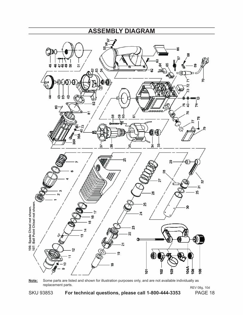
ASSEMBLY DIAgRAM
REV 08g, 10d
Note: Some parts are listed and shown for illustration purposes only, and are not available individually as replacement parts.
106:
Spa
de c
hise
l not
sho
wn.
107:
Bal
l poi
nt c
hise
l not
sho
wn.

SKU 93853 For technical questions, please call 1-800-444-3353 PAGE 19
LIMITED 1 YEAR / 90 DAY WARRANTYHarbor Freight Tools Co. makes every effort to assure that its products meet high
quality and durability standards, and warrants to the original purchaser that for a period of ninety days from date of purchase that the engine/motor, the belts (if so equipped), and the blades (if so equipped) are free of defects in materials and workmanship. Harbor Freight Tools also warrants to the original purchaser, for a period of one year from date of purchase, that all other parts and components of the product are free from defects in materials and workmanship (90 days if used by a professional contractor or if used as rental equipment). This warranty does not apply to damage due directly or indirectly, to misuse, abuse, negligence or accidents, repairs or alterations outside our facilities, normal wear and tear, or to lack of maintenance. We shall in no event be liable for death, injuries to persons or property, or for incidental, contingent, special or consequential damages arising from the use of our product. Some states do not allow the exclusion or limitation of incidental or consequential damages, so the above limitation of exclusion may not apply to you. THIS WARRANTY IS EXPRESSLY IN LIEU OF ALL OTHER WARRANTIES, EXPRESS OR IMPLIED, INCLUDING THE WARRANTIES OF MERCHANTABILITY AND FITNESS.
To take advantage of this warranty, the product or part must be returned to us with transportation charges prepaid. Proof of purchase date and an explanation of the complaint must accompany the merchandise. If our inspection verifies the defect, we will either repair or replace the product at our election or we may elect to refund the purchase price if we cannot readily and quickly provide you with a replacement. We will return repaired products at our expense, but if we determine there is no defect, or that the defect resulted from causes not within the scope of our warranty, then you must bear the cost of returning the product.
This warranty gives you specific legal rights and you may also have other rights which vary from state to state.
3491 Mission Oaks Blvd. • PO Box 6009 • Camarillo, CA 93011 • (800) 444-3353