Embed Size (px)
Citation preview
34th Space Symposium, Technical Track, Colorado Springs, Colorado, United States of America Presented on April 16, 2018
Copyright © 2017 by Dakota Wenberg/United States Naval Academy. All rights reserved. Page 1 of 12
DEMONSTRATING AUTONOMOUS SPACECRAFT ASSEMBLY WITH THE INTELLIGENT SPACE
ASSEMBLY ROBOT
MIDN Dakota Wenberg, USN
United States Naval Academy, [email protected]
MIDN Christopher Wellins, USN; MIDN Alex Hardy, USN; MIDN Thomas Lai, USN; Jin Kang
United States Naval Academy, [email protected]; [email protected]; [email protected];
ABSTRACT
The use of robotics in the space environment has been common throughout the last half century of space
exploration. However, robotic arms are rarely entrusted to perform large assembly tasks without a human in the
loop. Spacecraft and satellites are expensive so the risk associated with using autonomous systems with unproven
performance on delicate tasks is deemed too high risk. As our presence in space grows, autonomous robotic systems
may be the way forward as time lags associated with teleoperation are expected to cripple future space missions
beyond earth orbit. To capitalize on the advantages of autonomy in space robotics, new control algorithms are
needed to ensure the ability of robotic systems to react to dynamic environments while maintaining time-efficient
paths.
This project focuses on the derivation of a control system for spacecraft assembly applications using the
Intelligent Space Assembly Robot (ISAR). ISAR is comprised of two 6 degree of freedom robotic arms which are
housed in a 3U CubeSat form factor. The arms are equipped with a 2D camera at the end of each arm and a centrally
mounted 3D camera. This research tests a hybrid approach to robotic control that utilizes both model-based
trajectory planning and visual feedback to improve the performance of a robotic manipulator. The hybrid controller
will slide between the two controllers as it approaches the desired target or end position such that it is initially
controlled by the following a path derived from model-based planning and at the end is controlled by eye-in-hand
visual servoing.
This paper discusses the results of simulations which demonstrate the feasibility of autonomous robotic
functions using visual servoing and traditional trajectory planning are included. The planned operations and
assembly techniques will be discussed in preparation for the system’s launch to the ISS in 2019.
INTRODUCTION
Motivation for Research
The advent and proliferation of autonomous robotic systems has revolutionized terrestrial manufacturing.
Automated systems may improve production rates, lower costs, and eliminate danger to human operators. This
same revolution has yet to make the jump to space. Current robotic arms in space are primarily human controlled
and are not entrusted to independent operation.1 While construction of larger objects in orbit has been augmented
by teleoperated robotic arms, their operation is slowed by communications delays from the ground as well as the
cost and time required to launch a human operator into space.2 These impediments to robotic operations in space
impact the ability to assemble larger, complex spacecraft structures. The on orbit assembly of spacecraft has been
demonstrated to decrease deployment risk, and enable the assembly of systems too large to be flown in a single
launch vehicle. On orbit assembly also enables satellites and spacecraft to be repaired and upgraded in the future.
As an example of a larger spacecraft system built entirely on orbit, the ISS is comprised of 16 modules, Exhibit
1, which required over 40 flights including 26 space shuttle flights to assemble. This time and labor intensive process
34th Space Symposium, Technical Track, Colorado Springs, Colorado, United States of America Presented on April 16, 2018
Page 2 of 12
took over 20 years until the station was fully constructed. Most of the assembly was done using the astronaut crew
or the shuttle mounted Canadarm 1 and Canadarm 2 which have been on the station since April of 2001.3
Exhibit 1: Assembly breakdown of the ISS.4
Increased autonomy may improve the efficiency of robotic operations in space. A move away from an
overreliance on human-in-the-loop robotics may extend the usable reach of robots for space applications and
decrease the time required to perform robotic operations in and beyond earth orbit. Automating robotic operations
has been a focus of roboticists for over 50 years.5 There are several accepted methods for providing closed-loop
feedback to a robotic system to enable autonomous robotic operations. Many approaches use visual feedback to a
system to verify the relative position of the robotic arm and to inform future movements. Two examples of robotic
control which have been extensively researched an applied in terrestrial robotics are eye-in-hand visual servoing and
model-based trajectory planning. While current research has extensively explored autonomous control using each
of these approaches separately, or by augmenting robotic functions with visual and tactile feedback, there does not
appear to be research in the field of a sliding hybrid controller informed by the two approaches. By combining the
two approaches an autonomous robotic system will be able to assemble spacecraft using feedback to safely operate
in the dynamic environment while leveraging path planning to maintain time-efficiency.
Model-Based Trajectory Planning
There are several steps involved with creating a viable path for a robotic manipulator. Generating a path can be
done using a number various methods. The methods considered for this preliminary investigation include Dijkstra's
algorithm, A*, D*, and Probabilistic Road Mapping (PRM). Each of the path planning methods considered involves
deriving a connectivity graph of free space using, in this case, a point cloud returned from a 3D camera mounted to
the central body of a robotic arm. The space is decomposed into a grid of points called nodes and an interconnection
between two nodes is called an edge. The collection of nodes and edges comprises a graph. Using the resultant
graph, calculations can take into account multiple factors including the traversibility between graph nodes which
can weigh not only the distance in task or joint space, but additional factors such as “difficulty” describing the net
power usage for the designated connection. This research will assume that, since the robot is in space, the only
34th Space Symposium, Technical Track, Colorado Springs, Colorado, United States of America Presented on April 16, 2018
Page 3 of 12
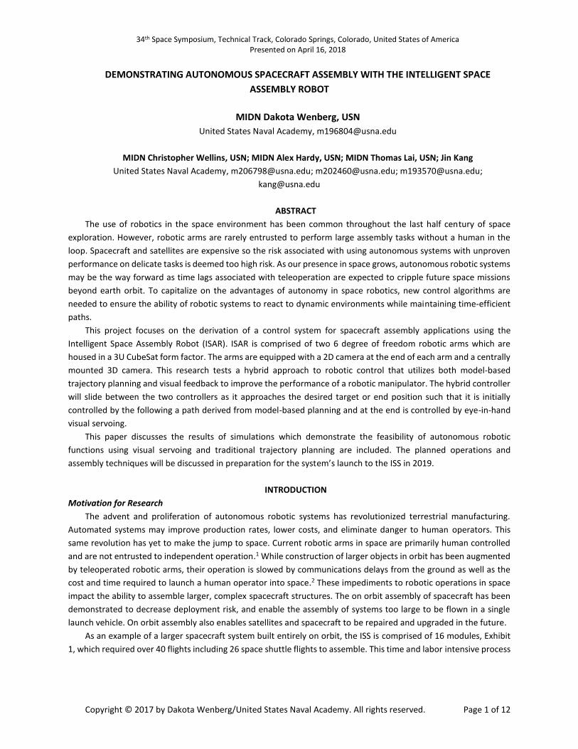
constraints to motion are the objects within the field of view. The following provides a brief description of some
common path planning methods.
Exhibit 2: Example of PRM path planning with obstacles in the field of view.6
Visual Servoing
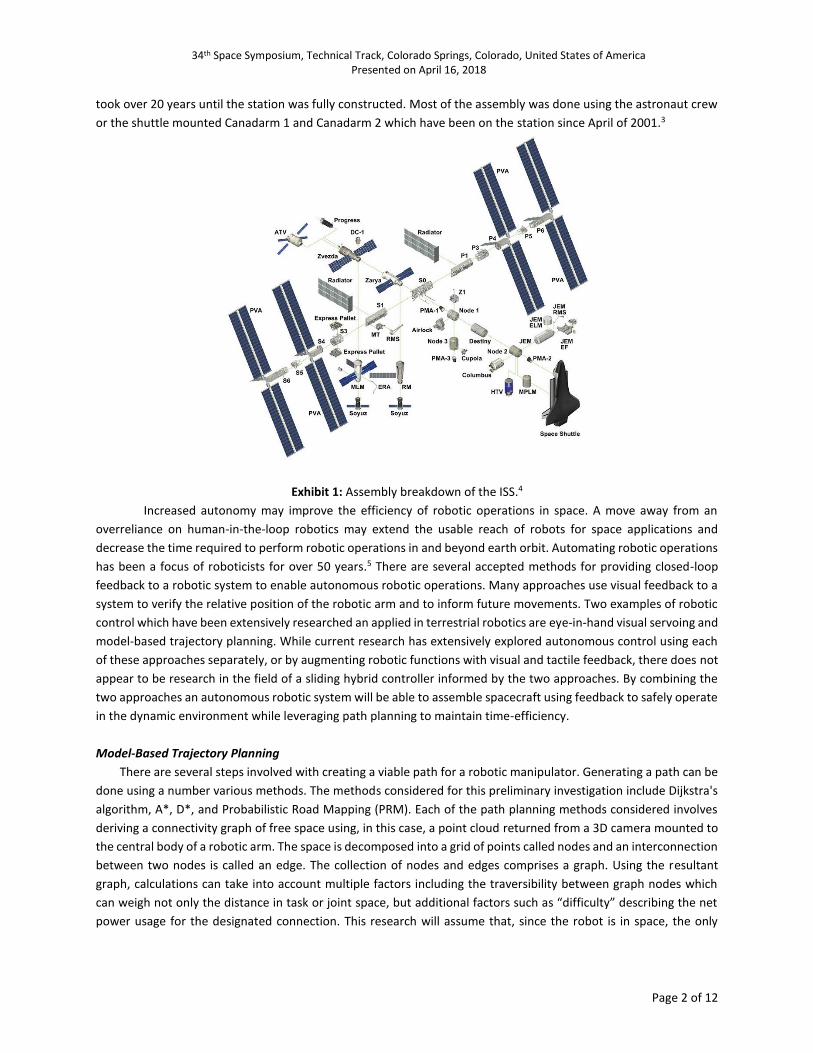
The basic principle of visual servoing is that the projected image of an object changes if the object moves relative
to the camera or if the camera moves relative to the object. Visual servoing commands a robotic arm to move such
that a particular object within a camera’s field of view changes position and orientation from a starting configuration
to match a desired ending configuration as shown in Exhibit 3.
Exhibit 3: Initial view of cube (left) and desired view of cube (right).
There are two prevalent types of visual servoing: fixed camera and eye-in-hand. Fixed camera visual
servoing is where there is a camera providing a third person or a “bird’s eye view” of the robotic arm and the object.
Eye-in-hand visual servoing is where the camera is positioned on the end-effector of the arm and moves with the
robotic arm. This allows the system to see more and to view objects from different angles. Image based visual
servoing is implemented using what’s called an image Jacobian. The image Jacobian is the product of the robotic
Jacobian, the camera’s intrinsic matrix, and the camera’s extrinsic matrix relating the camera frame to a frame on
the robotic arm. The intrinsic matrix describes the internal parameters of the camera. For the purposes of simplifying
this proof-of-concept, a conceptual 2D camera was used.
DEVELOPING A HYBRID CONTROLLER
Why is a Hybrid Controller Necessary?
34th Space Symposium, Technical Track, Colorado Springs, Colorado, United States of America Presented on April 16, 2018
Page 4 of 12
The two discussed approaches to autonomous control, eye-in-hand visual servoing and model-based trajectory
planning, are each viable methods of determining how to move a robotic arm. The problem arises when the
requirements of the space environment, and the limitations of the available sensors are taken into consideration.
Model-based trajectory planning works incredibly well in the terrestrial environment. Excellent cameras with great
resolution and large high powered computers can be used to get incredibly accurate depth data to determine the
position of a robotic arm. This means that the path that it follows is time-efficient and accurate. However because
of size, weight and power requirements, in the space environment less accurate sensors are the only options
available. This causes end position error in the model-based trajectory approach. This error is dangerous when
looking at spacecraft assembly because of the sensitivity and the cost of the parts being assembled. Another inherent
problem with model-based trajectory planning is the difficulty of the system to respond to a dynamic environment
as the controller does not always re-plan the trajectory well or if an object obstructs the field of view of the 3D
camera, the model-based controller alone will not be able to plan the trajectory of the arm. There are also problems
with eye-in-hand visual servoing. Most significantly, if the object which is being used as a reference leaves the field
of view of the camera, the robot can no longer be controlled using this method. There are also errors in the 2D image
produced by the resolution of the camera. These errors are worse when the camera is a distance away from the
object. However one of the advantages of eye-in-hand visual servoing is that as the distance to the object decreases,
the error decreases. This enables highly accurate end effector position.
There is also a difference in the trajectories between eye-in hand visual servoing and model-based trajectory
path planning. This comes from the way the two approaches calculate the change is joint angles such that the model
based-trajectory planning use all degrees of freedom to maintain the trajectory as close to a straight line meaning
that the path is more efficient. The eye-in-hand visual servoing approach creates a path which weaves in a sinusoidal
path to the target because of how the joint angles are calculated by the equations. This path is less direct than the
model-base trajectory planning controller.
By definition, a hybrid controller combines these two approaches. Model-based trajectory planning is used to
form a generalized understanding of the trajectory through free-space, and eye-in-hand visual servoing reduces the
positional error that exists in model-based trajectory planning while allowing the robotic arm to react to a dynamic
field of obstacles. The main method for demonstrating this improvement will be to measure the end-effector
positional accuracy as a difference between the desired and the actual position for each controller. In addition to
this highlighting the shortcomings of each controller by adding unexpected obstacles to simulations and testing.
Derivation of Hybrid Control Algorithm
The hybrid controller is a weighted sum of the two joint velocities: one from the visual servoing and the other
from the robotic Jacobian following waypoints in a pre-planned path. The weight of each controller is decided based
on the distance to the target position. As an analogy, this approach can be applied to a cruise missile. The missile,
when initially launched, is guided by long range guidance systems such as satellite guidance and tracking. However
as the missile approaches its target, it switches to automatic target recognition to refine the path to the target. In
that same fashion the hybrid controller seamlessly moves from the initial control using a pre-planned path to a
controller that refines movement using visual feedback until it reaches the desired position.
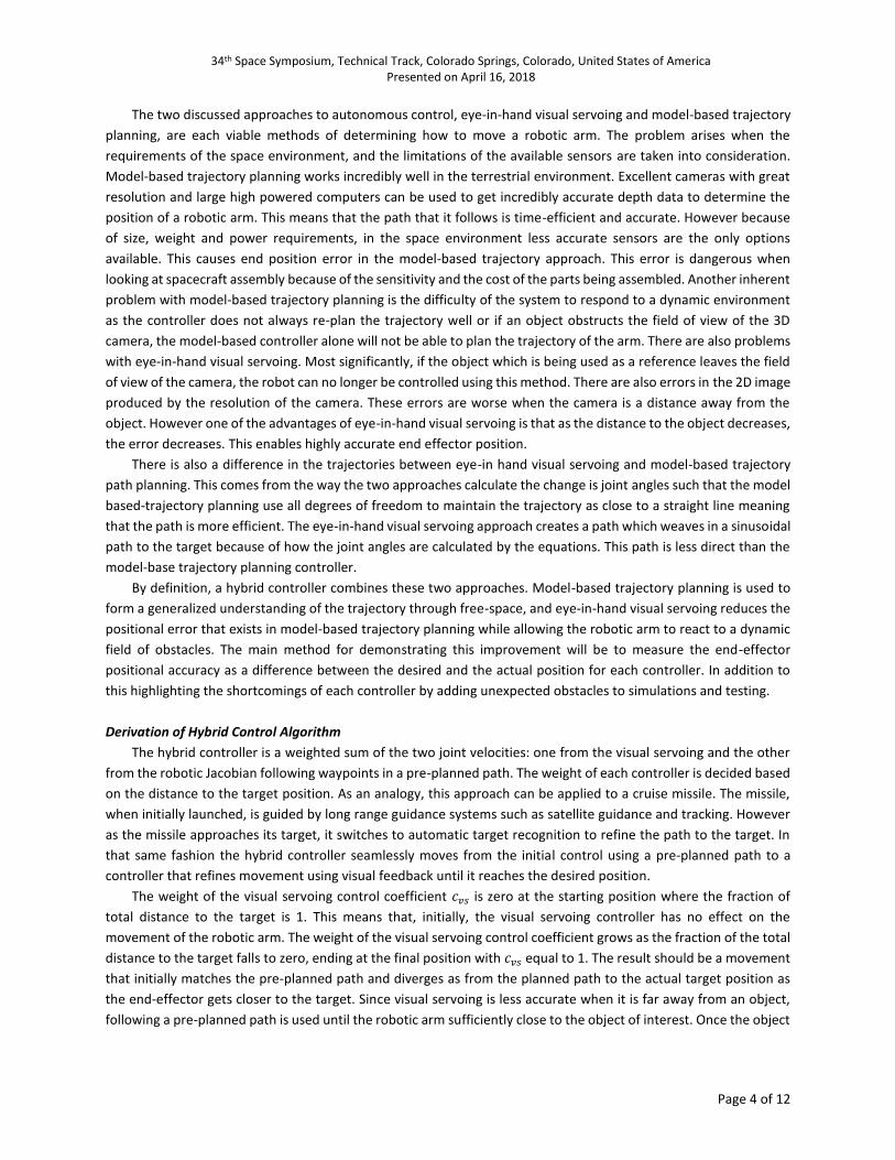
The weight of the visual servoing control coefficient 𝑐𝑣𝑠 is zero at the starting position where the fraction of
total distance to the target is 1. This means that, initially, the visual servoing controller has no effect on the
movement of the robotic arm. The weight of the visual servoing control coefficient grows as the fraction of the total
distance to the target falls to zero, ending at the final position with 𝑐𝑣𝑠 equal to 1. The result should be a movement
that initially matches the pre-planned path and diverges as from the planned path to the actual target position as
the end-effector gets closer to the target. Since visual servoing is less accurate when it is far away from an object,
following a pre-planned path is used until the robotic arm sufficiently close to the object of interest. Once the object
34th Space Symposium, Technical Track, Colorado Springs, Colorado, United States of America Presented on April 16, 2018
Page 5 of 12
is sufficiently close, visual servoing begins to drive the arm to an accurate end-effector position. The equations for
the implementation of the hybrid controller are
𝑚 =
|𝑋𝑔𝑜𝑎𝑙 − 𝑋𝑐𝑢𝑟𝑟𝑒𝑛𝑡|
|𝑋𝑔𝑜𝑎𝑙 − 𝑋𝑠𝑡𝑎𝑟𝑡|∈ [0,1]
(1)
𝑐𝑡 = 𝑚 (2)
𝑐𝑣𝑠 = 1 −𝑚 (3)
�̇�ℎ = 𝑐𝑡𝑞�̇� + 𝑐𝑣𝑠�̇�𝑣𝑠, (4)
where 𝑚, is a weighting factor which tracks the control coefficient, 𝑐𝑡 and 𝑐𝑣𝑠 which are the fractions of model-
based trajectory planning and visual servoing, respectively, which are used to weight the controller. The calculated
joint angles for the model-based trajectory planning, the visual servoing, and the hybrid are 𝑞�̇�, 𝑞𝑣𝑠̇ , and 𝑞ℎ̇. This set
of equations prescribe a smooth transition between velocity controllers that is proportional to the distance to the
desired end-effector position. The assumption is that, by making the hybrid system a smooth proportional
combination, some combination of the known stability regions of the two individual controllers will be preserved.
Note that the initial definition of 𝑚 given as an example of the dynamic weighting factor in Equation 1 assumes the
transition between controllers is based on distance. The next phase in the research will investigate alternative
representations of the weighting function to ensure stability and accuracy of the trajectory to the desired location.
A visual representation of the proportional weighting relationship is given in Exhibit 4.
Exhibit 4: Control coefficients for the “sliding” hybrid robotic controller evolving with fractional distance to the
target.
Simulation of Controller on Robotic Systems
An implementation of the hybrid controller was initially tested in MATLAB in a 2D simulation. The two DoF arm
was combined with a simulated 2D camera, and a single target point was presented to implement visual servoing.
The arm was constrained to move only in the X-Y plane so as to simplify the implementation of the hybrid
controller for the initial demonstration of feasibility. Another assumption was the use of simplified matrices such as
34th Space Symposium, Technical Track, Colorado Springs, Colorado, United States of America Presented on April 16, 2018
Page 6 of 12
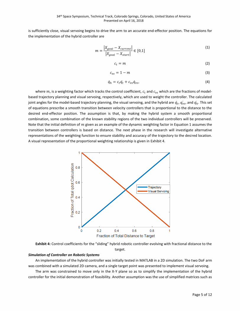
the camera intrinsics matrix which was a 2x2 matrix that returned a 1D image from a 2D field of view. The final key
assumption was that for the model-based path planning approach, the path was obstacle free and the fastest path
between the starting and ending point is a straight line. A birds-eye-view of the 2D space is shown in Exhibit 5. With
the coordinate system (red is the X-axis and green is the Y-axis) representing the coordinate system of the camera
and the blue asterisk (𝑃𝑑) representing a point in space which could be used as a reference for visual servoing.
Exhibit 5: 2D representation of camera and point
Simulation Results: Without Error
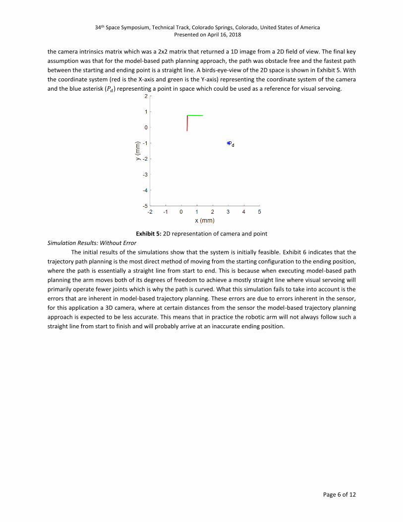
The initial results of the simulations show that the system is initially feasible. Exhibit 6 indicates that the
trajectory path planning is the most direct method of moving from the starting configuration to the ending position,
where the path is essentially a straight line from start to end. This is because when executing model-based path
planning the arm moves both of its degrees of freedom to achieve a mostly straight line where visual servoing will
primarily operate fewer joints which is why the path is curved. What this simulation fails to take into account is the
errors that are inherent in model-based trajectory planning. These errors are due to errors inherent in the sensor,
for this application a 3D camera, where at certain distances from the sensor the model-based trajectory planning
approach is expected to be less accurate. This means that in practice the robotic arm will not always follow such a
straight line from start to finish and will probably arrive at an inaccurate ending position.
34th Space Symposium, Technical Track, Colorado Springs, Colorado, United States of America Presented on April 16, 2018
Page 7 of 12
Exhibit 6: Initial Results of 2D representation of camera and point.
The path which the hybrid controller followed was initially similar to the model-based trajectory planned path
and then as 𝑚 was driven to zero as it approached the end position the hybrid controller was informed increasingly
by the visual servoing control.
Simulation Results: With Error
For this initial simulation it was assumed that there was no error in the model-based trajectory approach. The
second demonstration (Exhibit 7) shows how error was introduced in simulation using uniform sampling around a
mean value of the end position. Each time the position of the arm was updated an error term was included. The
error terms came from two sources, error in the 3D camera readings and error in the 2D camera readings. This better
simulates the reaction of a real system with these sensors attached.
34th Space Symposium, Technical Track, Colorado Springs, Colorado, United States of America Presented on April 16, 2018
Page 8 of 12
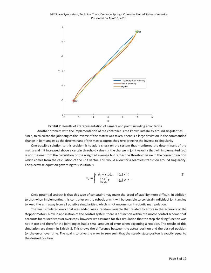
Exhibit 7: Results of 2D representation of camera and point including error terms.
Another problem with the implementation of the controller is the known instability around singularities.
Since, to calculate the joint angles the inverse of the matrix was taken, there is a large deviation in the commanded
change in joint angles as the determinant of the matrix approaches zero bringing the inverse to singularity.
One possible solution to this problem is to add a check on the system that monitored the determinant of the
matrix and if it increased above a certain threshold value (t), the change in joint velocity that will implemented (�̇�ℎ)
is not the one from the calculation of the weighted average but rather the threshold value in the correct direction
which comes from the calculation of the unit vector. This would allow for a seamless transition around singularity.
The piecewise equation governing this solution is
�̇�ℎ = {
𝑐𝑡𝑞�̇� + 𝑐𝑣𝑠�̇�𝑣𝑠 |�̇�ℎ| < 𝑡
(�̇�ℎ
|�̇�ℎ|) 𝑡 |�̇�ℎ| ≥ 𝑡
. (5)
Once potential setback is that this type of constraint may make the proof of stability more difficult. In addition
to that when implementing this controller on the robotic arm it will be possible to constrain individual joint angles
to keep the arm away from all possible singularities, which is not uncommon in robotic manipulation.
The final simulated error that was added was a random variable that related to errors in the accuracy of the
stepper motors. Now in application of the control system there is a function within the motor control scheme that
accounts for missed steps or oversteps, however we assumed for this simulation that the step checking function was
not in use and therefor the joint angles had a small amount of error when executing a rotation. The results of this
simulation are shown in Exhibit 8. This shows the difference between the actual position and the desired position
(or the error) over time. The goal is to drive the error to zero such that the steady state positon is exactly equal to
the desired position.
34th Space Symposium, Technical Track, Colorado Springs, Colorado, United States of America Presented on April 16, 2018
Page 9 of 12
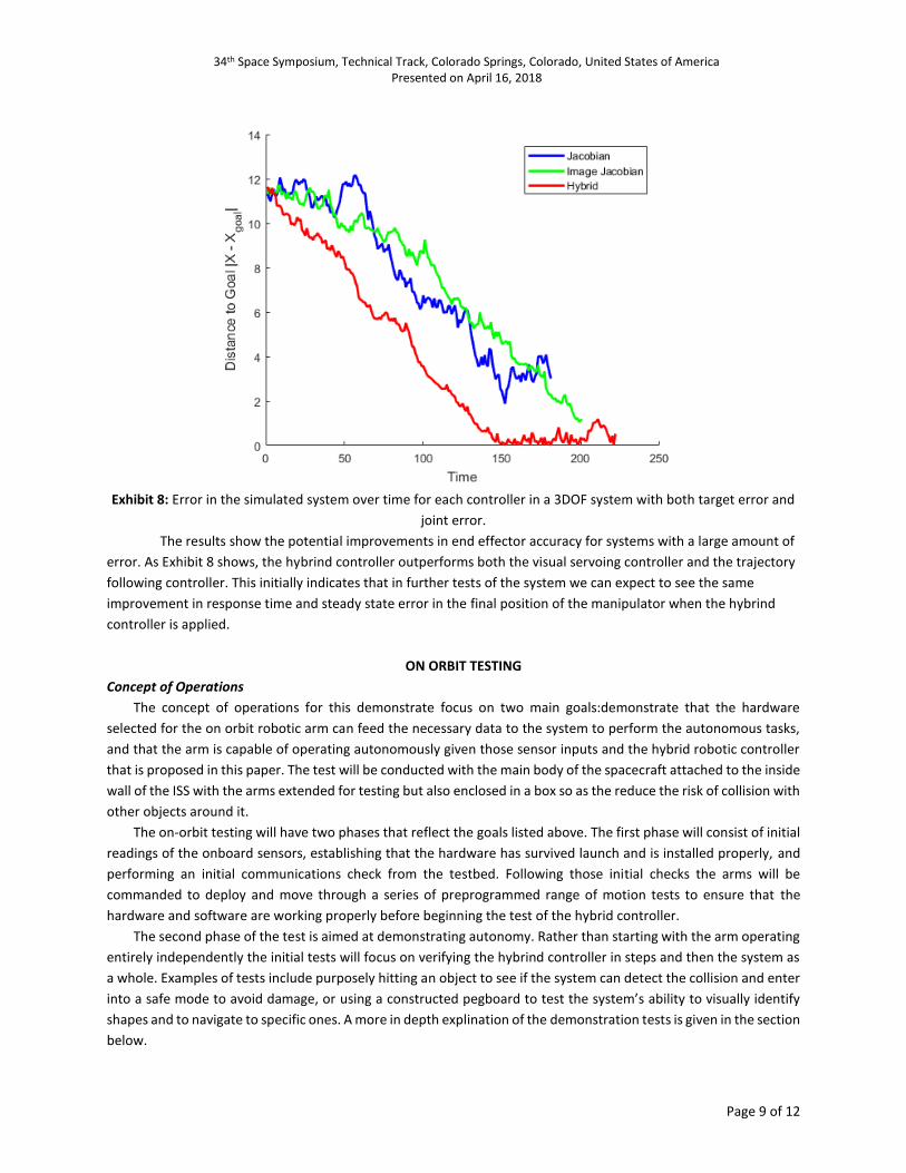
Exhibit 8: Error in the simulated system over time for each controller in a 3DOF system with both target error and
joint error.
The results show the potential improvements in end effector accuracy for systems with a large amount of
error. As Exhibit 8 shows, the hybrind controller outperforms both the visual servoing controller and the trajectory
following controller. This initially indicates that in further tests of the system we can expect to see the same
improvement in response time and steady state error in the final position of the manipulator when the hybrind
controller is applied.
ON ORBIT TESTING
Concept of Operations
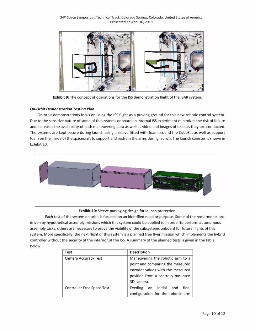
The concept of operations for this demonstrate focus on two main goals:demonstrate that the hardware
selected for the on orbit robotic arm can feed the necessary data to the system to perform the autonomous tasks,
and that the arm is capable of operating autonomously given those sensor inputs and the hybrid robotic controller
that is proposed in this paper. The test will be conducted with the main body of the spacecraft attached to the inside
wall of the ISS with the arms extended for testing but also enclosed in a box so as the reduce the risk of collision with
other objects around it.
The on-orbit testing will have two phases that reflect the goals listed above. The first phase will consist of initial
readings of the onboard sensors, establishing that the hardware has survived launch and is installed properly, and
performing an initial communications check from the testbed. Following those initial checks the arms will be
commanded to deploy and move through a series of preprogrammed range of motion tests to ensure that the
hardware and software are working properly before beginning the test of the hybrid controller.
The second phase of the test is aimed at demonstrating autonomy. Rather than starting with the arm operating
entirely independently the initial tests will focus on verifying the hybrind controller in steps and then the system as
a whole. Examples of tests include purposely hitting an object to see if the system can detect the collision and enter
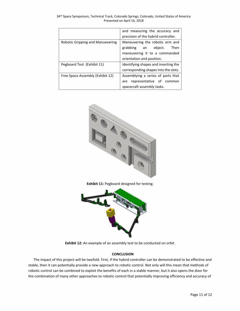
into a safe mode to avoid damage, or using a constructed pegboard to test the system’s ability to visually identify
shapes and to navigate to specific ones. A more in depth explination of the demonstration tests is given in the section
below.
34th Space Symposium, Technical Track, Colorado Springs, Colorado, United States of America Presented on April 16, 2018
Page 10 of 12
Exhibit 9: The concept of operations for the ISS demonstration flight of the ISAR system.
On-Orbit Demonstration Testing Plan
On-orbit demonstrations focus on using the ISS flight as a proving ground for this new robotic control system.
Due to the sensitive nature of some of the systems onboard an internal ISS experiment minimizes the risk of failure
and increases the availability of path maneuvering data as well as video and images of tests as they are conducted.
The systems are kept secure during launch using a sleeve fitted with foam around the CubeSat as well as support
foam on the inside of the spacecraft to support and restrain the arms during launch. The launch canister is shown in
Exhibit 10.
Exhibit 10: Sleeve packaging design for launch protection.
Each test of the system on orbit is focused on an identified need or purpose. Some of the requirments are
driven by hypothetical assembly missions which this system could be applied to in order to perform autonomous
assembly tasks, others are necessary to prove the viability of the subsystems onboard for future flights of this
system. More specifically, the next flight of this system is a planned free flyer mission which implements the hybrid
controller without the security of the interiror of the ISS. A summary of the planned tests is given in the table
below.
Test Description
Camera Accuracy Test Maneuvering the robotic arm to a
point and comparing the measured
encoder values with the measured
position from a centrally mounted
3D camera.
Controller Free Space Test Feeding an initial and final
configuration for the robotic arm
34th Space Symposium, Technical Track, Colorado Springs, Colorado, United States of America Presented on April 16, 2018
Page 11 of 12
and measuring the accuracy and
precision of the hybrid controller.
Robotic Gripping and Manuevering Maneuvering the robotic arm and
grabbing an object. Then
maneuvering it to a commanded
orientation and position.
Pegboard Test (Exhibit 11) Identifying shapes and inserting the
corresponding shapes into the slots.
Free Space Assembly (Exhibit 12) Assemblying a series of parts that
are representative of common
spacecraft assembly tasks.
Exhibit 11: Pegboard designed for testing.
Exhibit 12: An example of an assembly test to be conducted on orbit.
CONCLUSION
The impact of this project will be twofold. First, if the hybrid controller can be demonstrated to be effective and
stable, then it can potentially provide a new approach to robotic control. Not only will this mean that methods of
robotic control can be combined to exploit the benefits of each in a stable manner, but it also opens the door for
the combination of many other approaches to robotic control that potentially improving efficiency and accuracy of
34th Space Symposium, Technical Track, Colorado Springs, Colorado, United States of America Presented on April 16, 2018
Page 12 of 12
robotic control. Secondly, if the flight test are successful it will serve as an example of autonomous robotic arm
operations that have never before been seen in the space environment. This can have far-reaching implications to
the assembly of large spacecraft systems in the future.
ACKNOWLEDGEMENTS
The author gratefully acknowledges the generosity of Penny and Roe Stamps and the Stamps Family Charitable
Foundation. Additional funding has been provided by UNP/AFOSR/AFRL and the Program Executive Office Integrated
Warfare Systems (PEO-IWS). The author also like to acknowledge with appreciation the contributions of Dr. Michael
Kutzer, the program's primary adviser, Dr. Jin Kang, and Dr. Levi DeVries whose advice and support has allowed this
project to move from an idea to implementation. The author would also like to recognize the contributions of ENS
Ethan Doherty, ENS Benjamin Keegan, CDR Robert Bruninga, USN (ret), and Dr. Bradley Bishop. None of this would
have been possible without the personal support and caring mentorship of Dr. Jenelle Piepmeier and Dr. Joshua
Radice. Finally the author would like to thank the efforts of the midshipman and officer chain of command in Bancroft
Hall: LT Sean Heenan, MIDN Mike Wallace, MIDN Jack Gainer, MIDN Gavin Roser and my roommates Carly Naud and
Charmaine Solis.
1 D. Sternberg et al., "Reconfigurable ground and flight testing facility for robotic servicing, capture, and assembly," 2016 IEEE Aerospace Conference, Big Sky, MT, 2016, pp. 1-13.
2 K. Belvin, B. Doggett, and J. Watson, “In-Space Structural Assembly: Applications and Technology,” AIAA
SciTech 2016. pp. 1-5, 2016. 3 A. Kauderer, “International Space Station Assembly- Past Flights,” NASA Missions, International Space Station.,
2011. 4 n.a, ISS Assembly- Space Facts. 2017. 5 I. Asimov, and K. Frenkel, “Robots: Machines in Man’s Image,” Harmony Books. pp. 13, 1985. 6 P. Corke, “Robotics Toolbox for Matlab Release 10”.,2017.