Embed Size (px)
Citation preview
Demonstration-3D Printer
-CNC Milling Machine
ENGINEERING LABORATORY EE-100
Lahore University of Management SciencesElectrical Engineering Department, SSE
Non-conventional Manufacturing –3D Printing
• A process of making a three-dimensional solid object ofvirtually any shape from a digital model.
• A 3D printer is a limited type of industrial robot that iscapable of carrying out an additive process under computercontrol.
Creating .stl file from CAD
• Create your model in PTC Creo.
• Save your part file as .prt
• Then Proceed as:
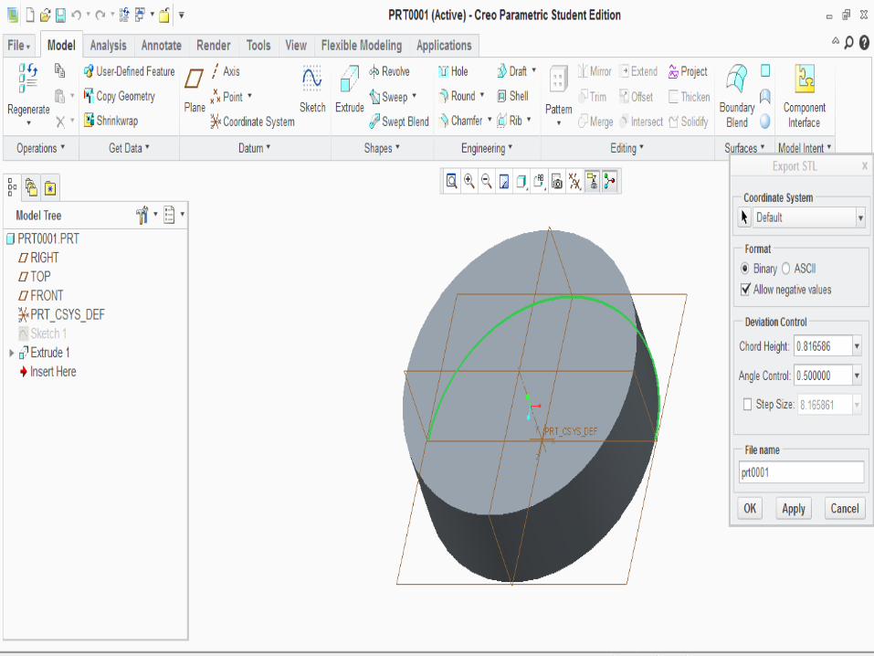
– File > Save As > File type stl, then Enter a file name.
– A dialog box will appear for the information of Chord height and Angle Control.
– Values for Chord Height and Angle Control determine the triangulation mesh. Small numbers make a fine mesh (larger file size), larger numbers yield a coarse mesh (smaller file size).
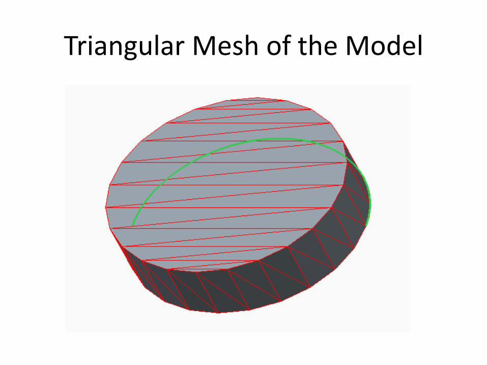
Triangular Mesh of the Model
Generating the Machine Specific File
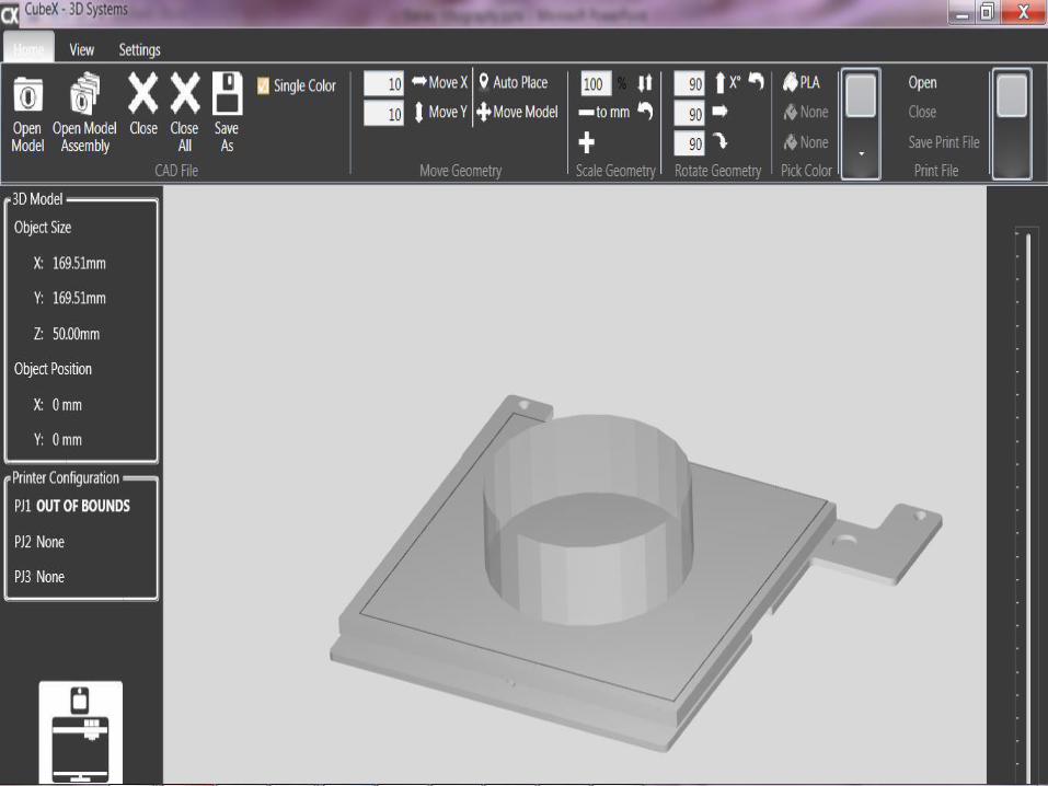
• We will be creating the .cubex files for our CUBE 3D Printing Machine.
• Open your saved .stl file in the CUBEX environment. • Adjust:
– Material Cartridge – Part Placement – Printing Scales/ Dimensions – Layer Thickness (This would affect the printing
resolution) – Part Density – Support Material
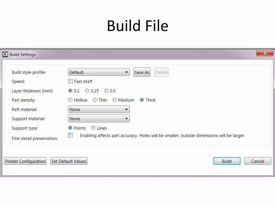
Build File
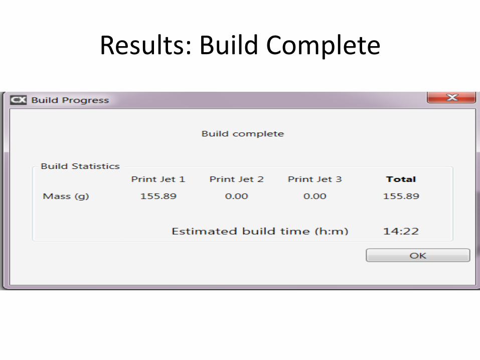
Results: Build Complete
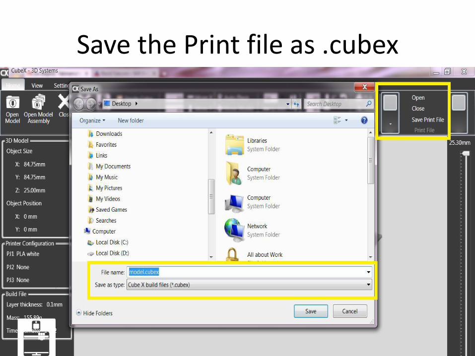
Save the Print file as .cubex
CNC Milling Machine
• CNC Milling Machine
– CNC machine is a Computerized Numerically Controlled machining process of using rotary cutters to remove material.
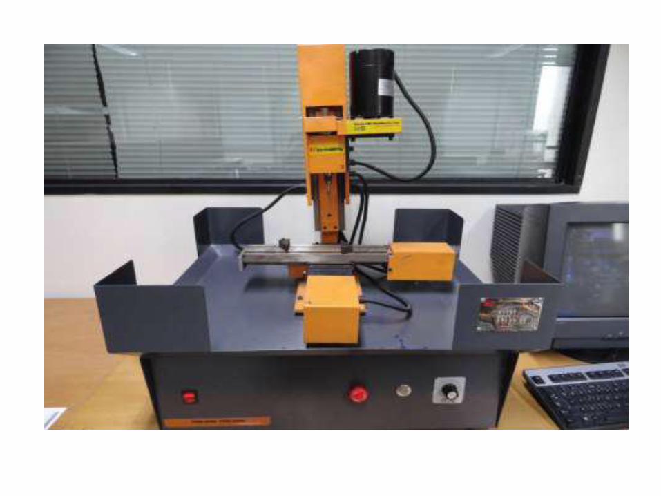
• Lab Apparatus of CNC Milling:
– SHARPE SXK01 is a desktop type, prototype making CNC machine. The machine is a multifunctional and cost effective apparatus with the following specifications:
• Three-dimensional numerical control tool path to simulation experiment.
• High-performance Mach3 control system.
• Manual direction to prepare G code to complete the processing of desired part.
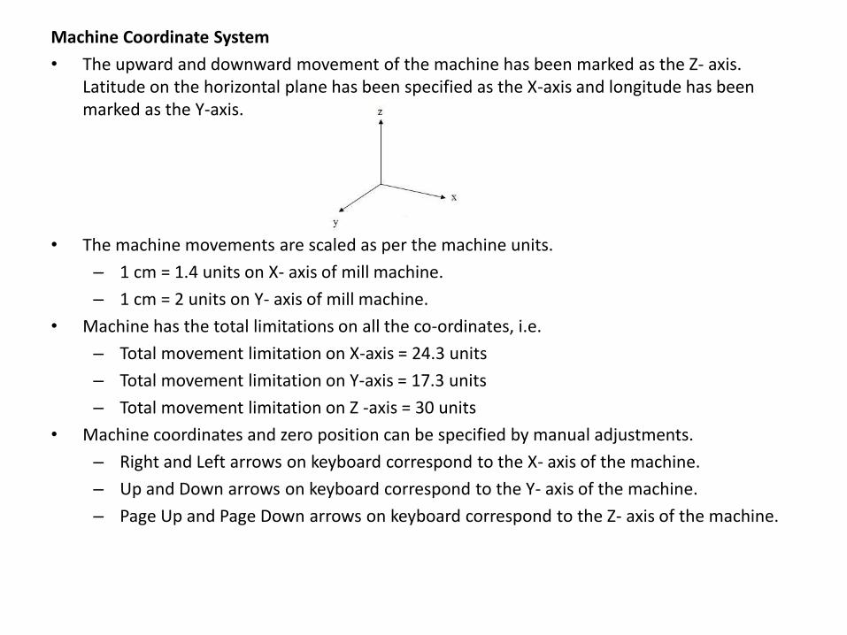
Machine Coordinate System
• The upward and downward movement of the machine has been marked as the Z- axis. Latitude on the horizontal plane has been specified as the X-axis and longitude has been marked as the Y-axis.
• The machine movements are scaled as per the machine units.
– 1 cm = 1.4 units on X- axis of mill machine.
– 1 cm = 2 units on Y- axis of mill machine.
• Machine has the total limitations on all the co-ordinates, i.e.
– Total movement limitation on X-axis = 24.3 units
– Total movement limitation on Y-axis = 17.3 units
– Total movement limitation on Z -axis = 30 units
• Machine coordinates and zero position can be specified by manual adjustments.
– Right and Left arrows on keyboard correspond to the X- axis of the machine.
– Up and Down arrows on keyboard correspond to the Y- axis of the machine.
– Page Up and Page Down arrows on keyboard correspond to the Z- axis of the machine.
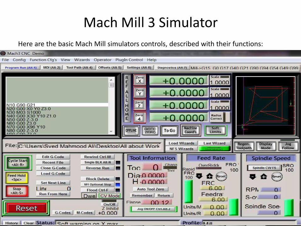
Mach Mill 3 Simulator
Here are the basic Mach Mill simulators controls, described with their functions:
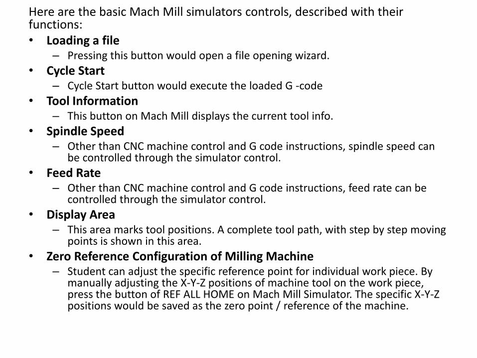
Here are the basic Mach Mill simulators controls, described with their functions:• Loading a file
– Pressing this button would open a file opening wizard.
• Cycle Start– Cycle Start button would execute the loaded G -code
• Tool Information– This button on Mach Mill displays the current tool info.
• Spindle Speed– Other than CNC machine control and G code instructions, spindle speed can
be controlled through the simulator control.
• Feed Rate– Other than CNC machine control and G code instructions, feed rate can be
controlled through the simulator control.
• Display Area– This area marks tool positions. A complete tool path, with step by step moving
points is shown in this area.
• Zero Reference Configuration of Milling Machine– Student can adjust the specific reference point for individual work piece. By
manually adjusting the X-Y-Z positions of machine tool on the work piece, press the button of REF ALL HOME on Mach Mill Simulator. The specific X-Y-Z positions would be saved as the zero point / reference of the machine.
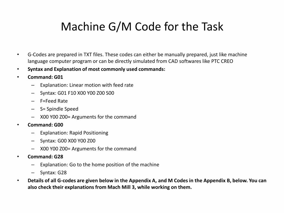
Machine G/M Code for the Task
• G-Codes are prepared in TXT files. These codes can either be manually prepared, just like machine language computer program or can be directly simulated from CAD softwares like PTC CREO
• Syntax and Explanation of most commonly used commands:
• Command: G01
– Explanation: Linear motion with feed rate
– Syntax: G01 F10 X00 Y00 Z00 S00
– F=Feed Rate
– S= Spindle Speed
– X00 Y00 Z00= Arguments for the command
• Command: G00
– Explanation: Rapid Positioning
– Syntax: G00 X00 Y00 Z00
– X00 Y00 Z00= Arguments for the command
• Command: G28
– Explanation: Go to the home position of the machine
– Syntax: G28
• Details of all G-codes are given below in the Appendix A, and M Codes in the Appendix B, below. You can also check their explanations from Mach Mill 3, while working on them.
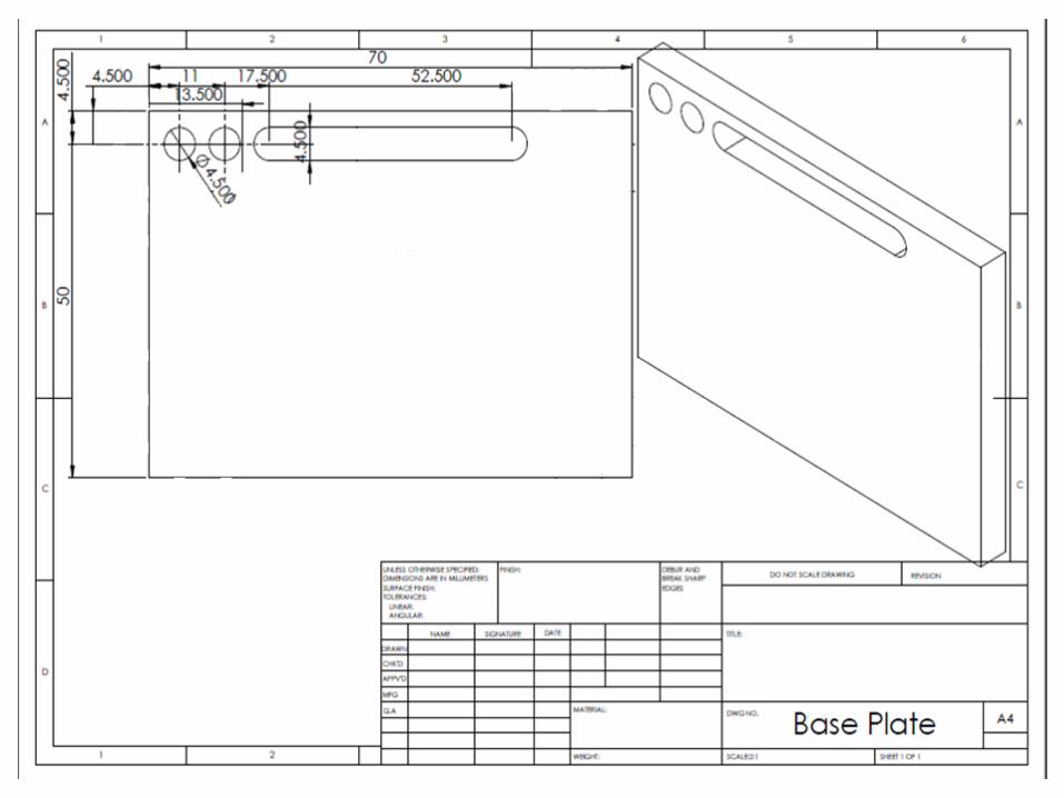
GCodes Example
• Below given figure shows, isometric view of a plate having 1 slot and 2 holes to be drilled in the plate.
• Dimensions are presented in standard position coordinates.
• The diameter of milling tool is 4.5. • The depth of machining is 5.GCodes:G00 - PositioningG01 - Straight interpolation
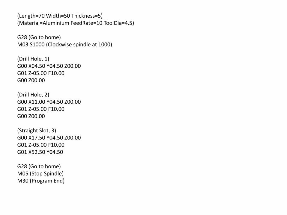
(Length=70 Width=50 Thickness=5) (Material=Aluminium FeedRate=10 ToolDia=4.5)
G28 (Go to home) M03 S1000 (Clockwise spindle at 1000)
(Drill Hole, 1)G00 X04.50 Y04.50 Z00.00G01 Z-05.00 F10.00G00 Z00.00
(Drill Hole, 2)G00 X11.00 Y04.50 Z00.00G01 Z-05.00 F10.00G00 Z00.00
(Straight Slot, 3)G00 X17.50 Y04.50 Z00.00G01 Z-05.00 F10.00G01 X52.50 Y04.50
G28 (Go to home) M05 (Stop Spindle) M30 (Program End)
Demonstration
Lab Task
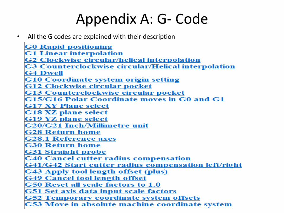
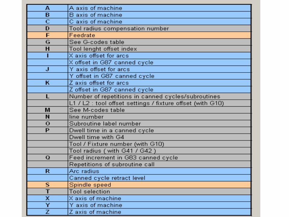
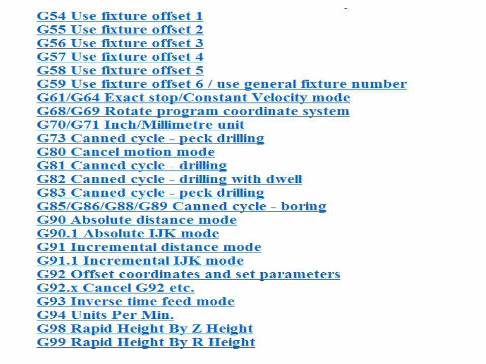
Appendix A: G- Code• All the G codes are explained with their description
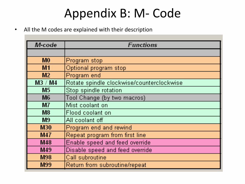
Appendix B: M- Code• All the M codes are explained with their description