Embed Size (px)
Citation preview
Demonstration of ultra-flattened dispersion in photonic crystal fibers
W.H. Reeves, J.C. Knight, and P.St.J. Russell Optoelectronics Group, School of Physics,
University of Bath, Claverton Down, Bath, BA2 7AY, UK
P.J. Roberts BlazePhotonics Ltd University of Bath Claverton Down Bath BA2 7AY
Abstract: We demonstrate photonic crystal fibers with ultra-flattened, near zero dispersion. Two micro-structured fibers showing dispersion of 0 ± 0.6 ps/nm.km from 1.24 µm-1.44 µm wavelength and 0 ± 1.2 ps/nm.km over 1 µm-1.6 µm wavelength have been measured. ©2002 Optical Society of America OCIS codes: (060.2270) Fiber Characterization; (060.2280) Fiber design and fabrication; (060.2430) Fibers, single mode
References and Links 1. J.C. Knight, T.A. Birks, P.St.J. Russell, and D.M. Atkin, “All-silica single-mode optical fiber with photonic
crystal cladding,” Opt. Lett. 21, 1547 (1996) 2. W.J. Wadsworth, A. Ortigosa-Blanch, J.C. Knight, T.A. Birks, T-P.M. Man and P.St.J. Russell,
“Supercontinuum generation in photonic crystal fibers and optical fiber tapers – A novel light source,” J. Opt. Soc. Am. B in press, (2002).
3. J.C. Knight, J. Arriaga, T.A. Birks, A. Ortigosa-Blanch, W.J. Wadsworth, and P.St.J Russell, “Anomalous dispersion in photonic crystal fiber,” IEEE Photon. Technol. Lett. 12, 807-809 (2000)
4. K.P. Hansen, J.R. Jensen, C.Jacobsen, H.R. Simonsen, J.Broeng, P.M.W. Skovgaard, A.Peterson and A. Bjarklev, “Highly Nonlinear Photonic Crystal Fiber with Zero-Dispersion at 1.55µm,” in Optical Fiber Commenication 2002, Vol. 70 of OSA Trends in Optics and Photonics Series (Optical Society of America, Washington, D.C., 2002), paper FA9.
5. J. Hansryd and P.A. Andrekson, “Broad-Band Continuous-Wave-Pumped Fiber Optical Parametric Amplifier with 49-dB Gain and Wavelength-Conversion Efficiency,” IEEE Photon. Technol. Lett. 13, 194 (2001)
6. Y. Takushima, and K Kikuchi, “10-GHz, Over 20-Channel Multiwavelength Pilse Source by Slicing Super-Continuum Spectrum Generated in Normal-Dispersion Fiber”, IEEE Photon. Technol. Lett. 11, 322, (1999)
7. A. Ferrando, E. Silvestre, J.J. Miret, and P. Andres, “Nearly zero ultraflattened dispersion in photonic crystal fibers,” Opt. Lett. 25, 790 (2000)
8. A. Ferrando, E. Silvestre, and P. Andres, “Designing the properties of dispersion-flattened photonic crystal fiber,” Opt. Express 9, 687 (2001) http://www.opticsexpress.org/abstract.cfm?URI=OPEX-9-13-687
9. M. Tateda, N. Shibata, and S. Seikai, “Interferometric method for chromatic dispersion measurement in a single-mode optical fiber,” IEEE J. Quantum Electron. QE-17, 404 (1981)
10. R.F. Cregan, J.C. Knight,P.St.J. Russell and P.J. Roberts, “Distribution of spontaneous emission from an Er3+-doped photonic crystal fiber,” 1999, J. Lightwave Tech. 17 2138-41
11. M.J. Steel, T.P. White, C.M. de Sterke, R.C. McPhedran and L.C. Botten, “Symmetry and degeneracy in microstructured optical fibers,” 2001, Opt. Lett. 26, 488
12. T.A. Birks, J.C. Knight, and P.St.J. Russell, “Endlessly single-mode photonic crystal fiber,” Opt. Lett. 22, 961 (1997)
1. Introduction Photonic crystal fiber (PCF) is formed from a strand of silica glass with an array of microscopic air channels running along its length [1]. A guiding core can be created by filling one channel with glass. In conventional step-index fibers, group velocity dispersion (GVD) is usually dominated by the dispersion of the bulk silica. In PCF, however, the additional design
(C) 2002 OSA 15 July 2002 / Vol. 10, No. 14 / OPTICS EXPRESS 609#1325 - $15.00 US Received June 07, 2002; Revised July 01, 2002
parameters of hole diameter, d, and hole-to-hole spacing, Λ, enable much greater flexibility in the design of dispersion to suit the required application. For example, PCFs have been reported with zero GVD point shifted to the green – in conventional step-index fibers the zero dispersion wavelength is at ~1.3 µm. These unusual fibers have very small cores and are very efficient at generating supercontinuum light from fsec Ti:Sapphire laser pulses [2,3].
PCFs with zero dispersion wavelengths around the 1.5 µm communications window have also recently been demonstrated [4]. However, these fibers have significant higher-order dispersion (around 0.25 ps/nm2.km). Here we present PCF that has flattened, near zero, dispersion over a very much wider wavelength range – from 1 µm to 1.6 µm. These fibers have many potential uses such as optical parametric amplification [5] and supercontinuum generation in the infrared [6].
2. PCF With Near Zero Flattened Dispersion
PCF with ultra-flattened dispersion is investigated numerically in two papers by Ferrando et al. [7,8]. By optimizing d and Λ, they predicted that it is possible to create a PCF with a dispersion of ±1 ps/nm.km over a wavelength range of 543 nm centered at approximately 1.52 µm (d ≈ 0.73 µm, Λ ≈ 3.02 µm). Alternatively, a dispersion of D = ±0.5 ps/nm.km could be achieved over a wavelength range of 428 nm (d ≈ 0.63µm, Λ ≈ 2.64µm).
The fabrication of this type of PCF is non-trivial because the required hole diameters are sub-micron. Standard PCF fabrication [1] involves stacking silica capillaries into a hexagonal close packed structure, and replacing the central capillary with a glass rod to form a solid core. The unwanted holes between the capillaries tend to deform the structure when they collapse – normally a negligible effect with large-hole PCF. In fibers with ultra-low dispersion, however, precise control of hole shape, size, pitch and core diameter is essential.
3. Experimental Results
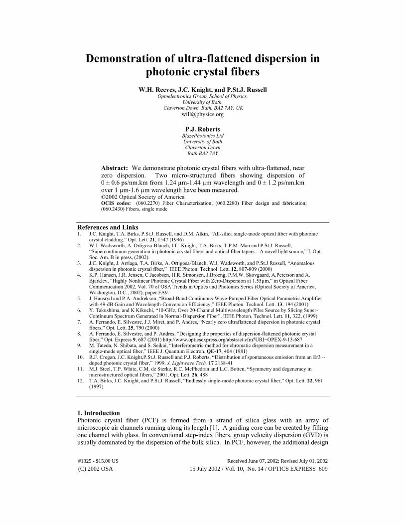
In our first fiber we targeted a hole diameter of d ≈ 0.63 µm and a pitch Λ ≈ 2.64 µm, these values being suggested by the numerical modeling. It contained 186 holes, and the target values were attained using an iterative fabrication process. After each draw d and Λ were determined using scanning electron microscopy and the dispersion measured using a low coherence interferometric technique [9]. Figure 1 shows electron micrographs of one of the fibers.
Fig. 1 A photonic crystal fiber with 7 periods in the cladding and with Λ ≈ 2.5µm and d ≈ 0.5µm.
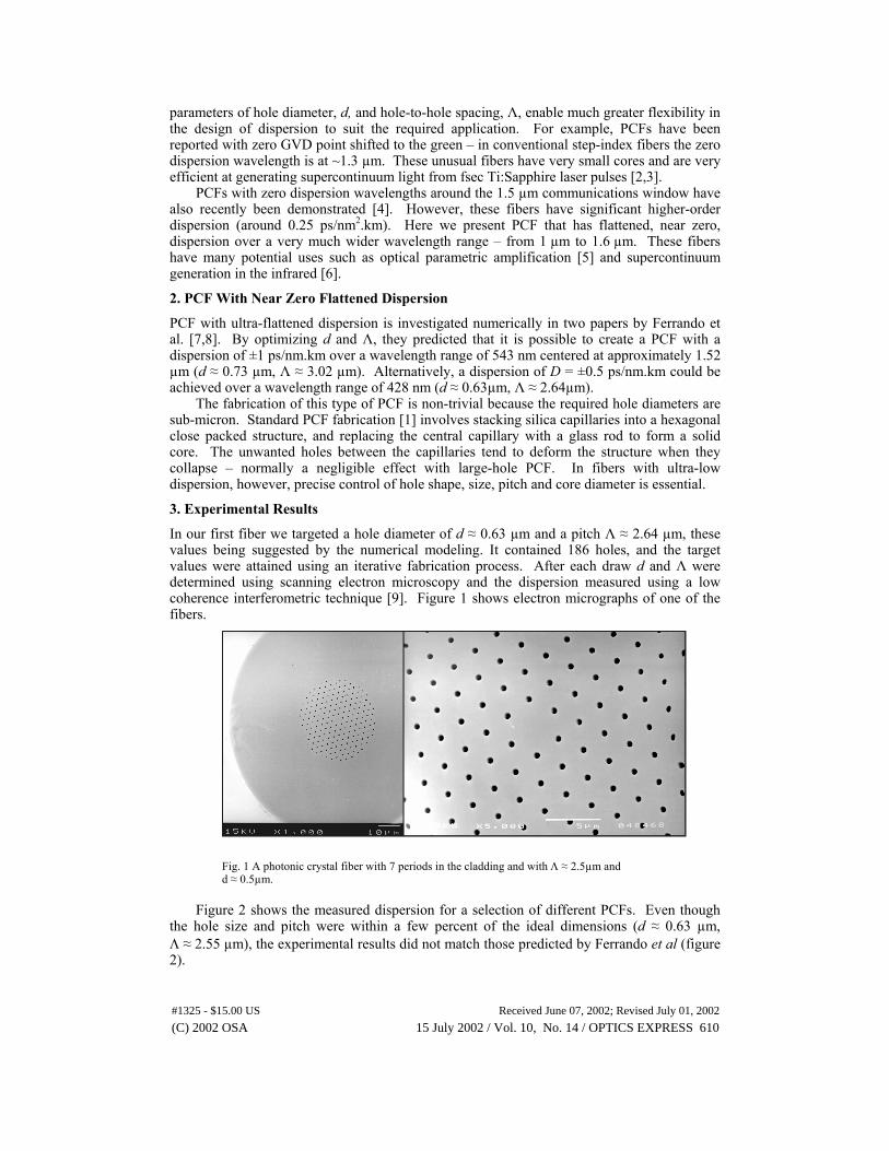
Figure 2 shows the measured dispersion for a selection of different PCFs. Even though
the hole size and pitch were within a few percent of the ideal dimensions (d ≈ 0.63 µm, Λ ≈ 2.55 µm), the experimental results did not match those predicted by Ferrando et al (figure 2).
(C) 2002 OSA 15 July 2002 / Vol. 10, No. 14 / OPTICS EXPRESS 610#1325 - $15.00 US Received June 07, 2002; Revised July 01, 2002
-10
-5
0
5
10
15
20
25
1 1.1 1.2 1.3 1.4 1.5 1.6
Wavelength (µm)
Dis
pers
ion
ps/
nm.k
m
d= 0.63, Λ=2.46
d= 0.575, Λ=2.45
d= 0.65, Λ=2.41
d= 0.63, Λ=2.55
Fig. 2. Measured dispersion for a selection of 7-period PCFs. Although the theoretical ideal fiber parameters were almost reached, the experimental and theoretical results did not match.
Our explanation for the discrepancy in GVD is that the guided mode was not sufficiently
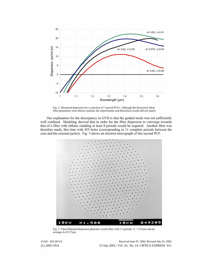
well confined. Modeling showed that in order for the fiber dispersion to converge towards that of a fiber with infinite cladding at least 8 periods would be required. Another fiber was therefore made, this time with 455 holes (corresponding to 11 complete periods between the core and the external jacket). Fig. 3 shows an electron micrograph of this second PCF.
Fig. 3. Ultra-flattened dispersion photonic crystal fiber with 11 periods. Λ = 2.47µm and an average d of 0.57µm.
(C) 2002 OSA 15 July 2002 / Vol. 10, No. 14 / OPTICS EXPRESS 611#1325 - $15.00 US Received June 07, 2002; Revised July 01, 2002
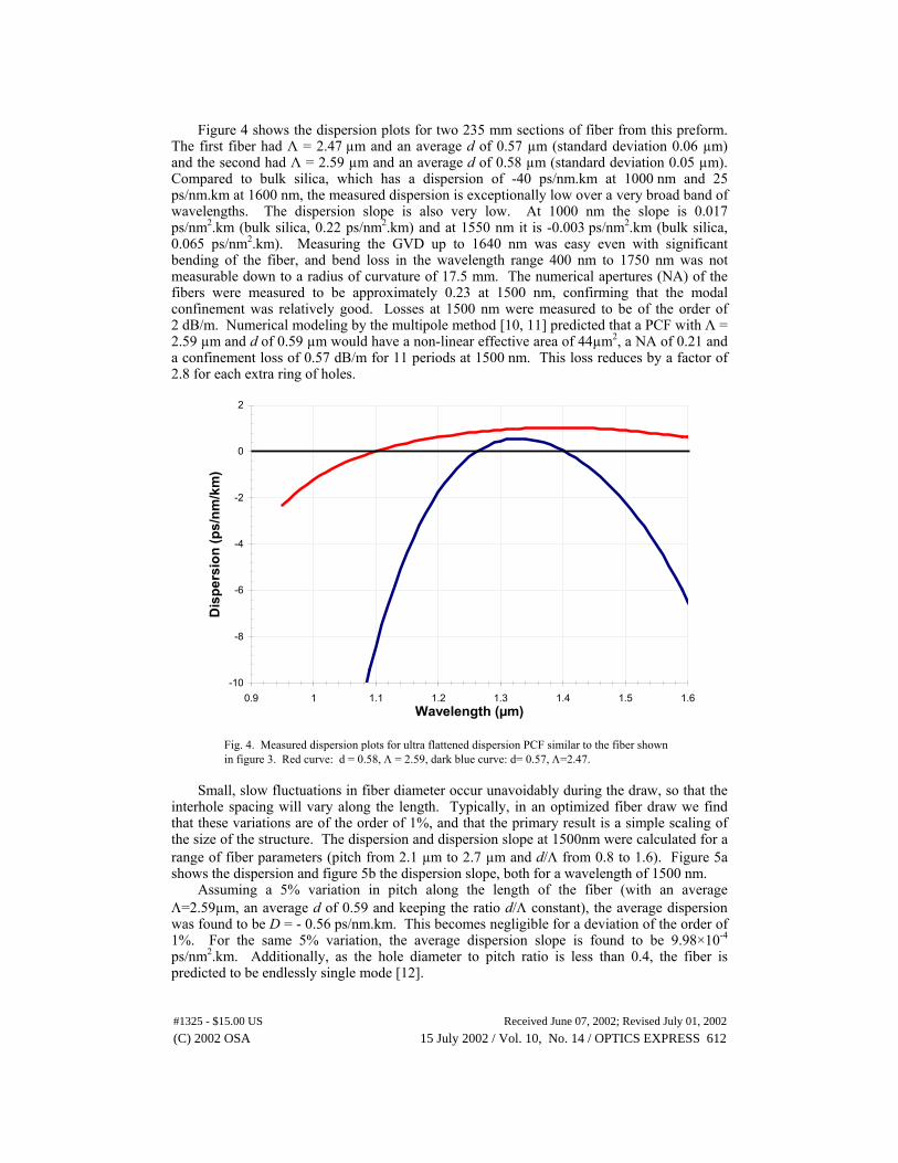
Figure 4 shows the dispersion plots for two 235 mm sections of fiber from this preform.
The first fiber had Λ = 2.47 µm and an average d of 0.57 µm (standard deviation 0.06 µm) and the second had Λ = 2.59 µm and an average d of 0.58 µm (standard deviation 0.05 µm). Compared to bulk silica, which has a dispersion of -40 ps/nm.km at 1000 nm and 25 ps/nm.km at 1600 nm, the measured dispersion is exceptionally low over a very broad band of wavelengths. The dispersion slope is also very low. At 1000 nm the slope is 0.017 ps/nm2.km (bulk silica, 0.22 ps/nm2.km) and at 1550 nm it is -0.003 ps/nm2.km (bulk silica, 0.065 ps/nm2.km). Measuring the GVD up to 1640 nm was easy even with significant bending of the fiber, and bend loss in the wavelength range 400 nm to 1750 nm was not measurable down to a radius of curvature of 17.5 mm. The numerical apertures (NA) of the fibers were measured to be approximately 0.23 at 1500 nm, confirming that the modal confinement was relatively good. Losses at 1500 nm were measured to be of the order of 2 dB/m. Numerical modeling by the multipole method [10, 11] predicted that a PCF with Λ = 2.59 µm and d of 0.59 µm would have a non-linear effective area of 44µm2, a NA of 0.21 and a confinement loss of 0.57 dB/m for 11 periods at 1500 nm. This loss reduces by a factor of 2.8 for each extra ring of holes.
-10
-8
-6
-4
-2
0
2
0.9 1 1.1 1.2 1.3 1.4 1.5 1.6Wavelength (µm)
Dis
pers
ion
(ps/
nm/k
m)
Fig. 4. Measured dispersion plots for ultra flattened dispersion PCF similar to the fiber shown in figure 3. Red curve: d = 0.58, Λ = 2.59, dark blue curve: d= 0.57, Λ=2.47.
Small, slow fluctuations in fiber diameter occur unavoidably during the draw, so that the
interhole spacing will vary along the length. Typically, in an optimized fiber draw we find that these variations are of the order of 1%, and that the primary result is a simple scaling of the size of the structure. The dispersion and dispersion slope at 1500nm were calculated for a range of fiber parameters (pitch from 2.1 µm to 2.7 µm and d/Λ from 0.8 to 1.6). Figure 5a shows the dispersion and figure 5b the dispersion slope, both for a wavelength of 1500 nm.
Assuming a 5% variation in pitch along the length of the fiber (with an average Λ=2.59µm, an average d of 0.59 and keeping the ratio d/Λ constant), the average dispersion was found to be D = - 0.56 ps/nm.km. This becomes negligible for a deviation of the order of 1%. For the same 5% variation, the average dispersion slope is found to be 9.98×10⁻⁴ ps/nm2.km. Additionally, as the hole diameter to pitch ratio is less than 0.4, the fiber is predicted to be endlessly single mode [12].
(C) 2002 OSA 15 July 2002 / Vol. 10, No. 14 / OPTICS EXPRESS 612#1325 - $15.00 US Received June 07, 2002; Revised July 01, 2002
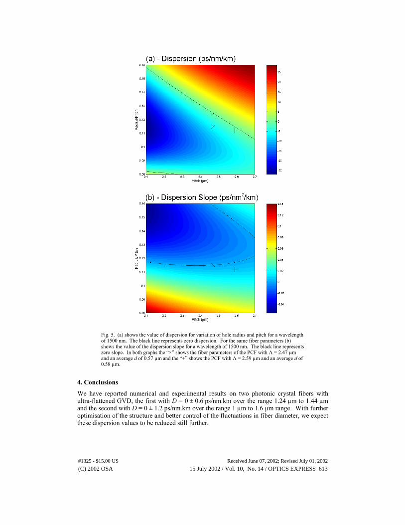
Fig. 5. (a) shows the value of dispersion for variation of hole radius and pitch for a wavelength of 1500 nm. The black line represents zero dispersion. For the same fiber parameters (b) shows the value of the dispersion slope for a wavelength of 1500 nm. The black line represents zero slope. In both graphs the “×” shows the fiber parameters of the PCF with Λ = 2.47 µm and an average d of 0.57 µm and the “+” shows the PCF with Λ = 2.59 µm and an average d of 0.58 µm.
4. Conclusions
We have reported numerical and experimental results on two photonic crystal fibers with ultra-flattened GVD, the first with D = 0 ± 0.6 ps/nm.km over the range 1.24 µm to 1.44 µm and the second with D = 0 ± 1.2 ps/nm.km over the range 1 µm to 1.6 µm range. With further optimisation of the structure and better control of the fluctuations in fiber diameter, we expect these dispersion values to be reduced still further.
(C) 2002 OSA 15 July 2002 / Vol. 10, No. 14 / OPTICS EXPRESS 613#1325 - $15.00 US Received June 07, 2002; Revised July 01, 2002