Embed Size (px)
Citation preview
BULETINUL INSTITUTULUI POLITEHNIC DIN IAŞI Publicat de
Universitatea Tehnică „Gheorghe Asachi” din Iaşi Tomul LIX (LXIII), Fasc. 1, 2013
Secţia CONSTRUCŢII. ARHITECTURĂ
DENMARK CASE STUDY CONCERNING RESIDENTIAL BUILDINGS REHABILITATION METHODOLOGY
ACCORDING TO BE10 ENERGY DEMAND CALCULATION SOFTWARE AND BR10 REGULATION
BY
GABRIEL TEODORIU1,* and KIRSTEN ENGELUND THOMSEN2
1“Gheorghe Asachi” Technical University of Iaşi Faculty of Civil Engineering and Building Services
2Aalborg University, Denmark Statens Byggeforskningsinstitut – Energy and Environment
Received: December 3, 2012 Accepted for publication: December 19, 2012
Abstract. This paper summarizes the key aspects of a case study regarding
an initial and renovated states of a residential building located in a residential complex in Denmark which has been involved in IEA Annex 56 international project whose primary objectives, as highlighted in this paper, are to select exemplary case studies to encourage decision makers to reflect on efficient and cost effective renovation methods, synthesize additional benefits achieved in the renovation process, determine cost effective combinations of energy efficiency and renewable energy supply measures. Following the directions of the EU methodology the case study aims to demonstrate the benefits of a rehabilitation process for a building connected to a district heating system and to emerge the opportunity to adapt it in the Romanian context.
Key words: heating demand; energy consumption; energy calculation; residential buildings renovation.
*Corresponding author: e-mail: [email protected]
58 Gabriel Teodoriu and Kirsten Engelund Thomsen
1. Introduction
1.1. Brief Description of IEA Annex 56
Over the last years, the sustainable development principles have been
applied in various standards and regulations for energy consumption in buildings that specify consistently improved levels for energy efficiency. These principles mainly focus on new buildings and do not respond effectively to the numerous technical, functional and economic constraints of the existing building stock, resulting in expensive processes and complex procedures, rarely accepted by occupants, owners or investors.
However, with an objective of mitigating climate change, renewable energy supply measures can sometimes be at least as cost effective as energy conservation and efficiency measures. Case studies in progress revealed that, in existing buildings, cost-effective renovation solution often results from a combination of energy efficiency and implementation of new renewable energy supply measures. A meticulous investigation is necessary to show where balance point lies between these two types of measures from a cost–benefit perspective. This involves determining how the best performance (in terms of less energy consumption, less carbon dioxide emissions and overall added value achieved by the renovation) would be achieved with the least effort (in terms of investment, interventions in the building and disturbance of occupants).
The overall added value consists in a broad range of non-energy benefits (NEBs) resulted from home retrofits that have been identified and classified according to the perspective of their chief beneficiary: the utility and society, or program participants, synthesized as in Tables 1 and 2 (Amann, 2006).
Table 1
Utility and Society Non-Energy Benefits (Amann, 2006) Utility perspective Societal perspective
Transmission and/or distribution savings Peak load reductions
Economic impacts (job creation, tax revenue) Improved housing stock/preservation Emissions/environmental impacts Health and safety benefits Water and waste-water savings
Therefore, the study had been realized according with the methodology
for energy in direct relationship with optimized building renovation solutions, as a basis for future standards to be used by interested private entities and agencies for their renovation decisions, as well as by governmental agencies for the definition of regulations and their implementation.
Bul. Inst. Polit. Iaşi, t. LIX (LXIII), f. 1, 2013 59
Table 2
Rehabilitation Program Participant Non-Energy Benefits (Amann, 2006) General benefit Specifics/examples
Financial benefits (other than energy cost savings)
Program incentives: rebates, low interest financing, subsidized Home assessment/diagnosis Water and waste-water bill savings Reduced equipment repair and maintenance Increased home resale or rental value Improved home durability
Comfort benefits Improved airflow Reduced drafts and temperature swings Better humidity control
Aesthetic benefits
More attractive windows, appliances, etc. Less dust Reduced/eliminated mold and/or water damage Protection of furnishings Dimmable lighting
Health and safety benefits Improved respiratory health Reduced allergic reactions Lower fire/accident risk (from gas equipment)
Noise reduction benefits Quieter HVAC (Heating, Ventilation, and Air Conditioning) and other equipment Less external noise intrusion
Education-related benefits
Reduced transaction costs (knowing what to look for when purchasing equipment; ease in locating appropriate products) Persistence of savings Greater understanding of home operation
Convenience benefits
Automatic thermostat controls Easier filter changes Faster hot water delivery Less dusting and vacuuming
Other benefits
Greater control over energy use/energy bill Reduced sick days from school and work Ease of selling home Enhanced pride/prestige Improved sense of environmental responsibility Enhanced peace of mind/responsibility for family well-being
1.2. Brief Description of the Case Study Residential Complex Area
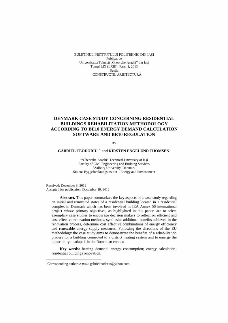
As a Danish case study for IEA Annex 56 have been chosen the Traneparken complex which consists in a couple of three multistorey blocks of flats situated in North-West of Hvalso in Lejre municipality, at 55 km far from Copenhagen, located North from the railroad, bordered by residential neighborhoods to the South and West and in the North by a large Greenfield, as revealed in Fig.1.
60 Gabriel Teodoriu and Kirsten Engelund Thomsen
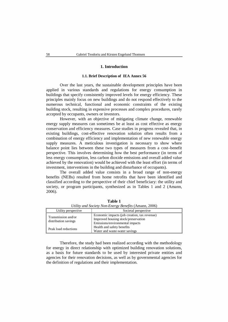
The initial state is presented in Fig. 2 left and, nowadays, the blocks are included in a thermal rehabilitation program (Fig. 2 right).
Fig. 1– Location of Traneparken complex.
Fig. 2 – Site pictures with block A envelope (walls, windows and roof) of the Traneparken residential complex.
2. Be10 Energy Demand Calculations – Reference Case
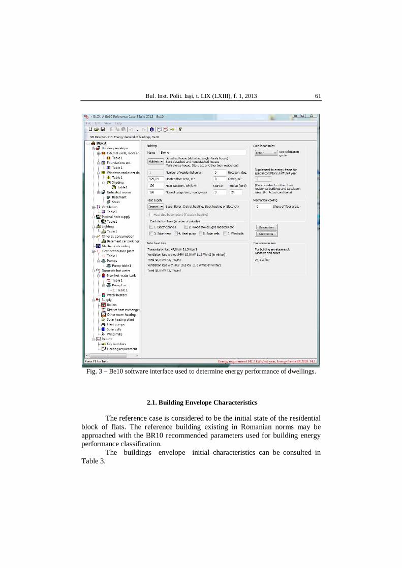
Be10 is a computer software developed by SBi (Statens Byggefor-skningsinstitut, Denmark) following methodologies used in experimental validated dynamic models incorporated in an advanced computing program – BSim (software developed by the same institute) (Fig. 3) (Teodoriu & Șerbănoiu, 2012).
Bul. Inst. Polit. Iaşi, t. LIX (LXIII), f. 1, 2013 61
Fig. 3 – Be10 software interface used to determine energy performance of dwellings.
2.1. Building Envelope Characteristics
The reference case is considered to be the initial state of the residential block of flats. The reference building existing in Romanian norms may be approached with the BR10 recommended parameters used for building energy performance classification.
The buildings envelope initial characteristics can be consulted in Table 3.
62 Gabriel Teodoriu and Kirsten Engelund Thomsen
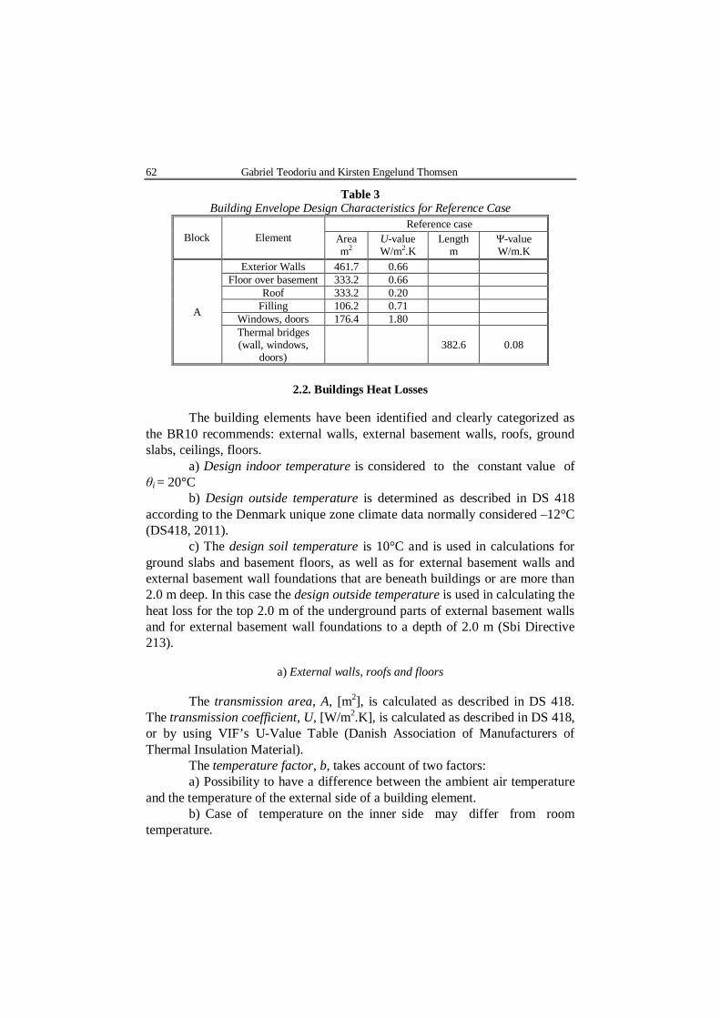
Table 3 Building Envelope Design Characteristics for Reference Case
Block Element Reference case
Area m2
U-value W/m2.K
Length m
Ψ-value W/m.K
A
Exterior Walls 461.7 0.66 Floor over basement 333.2 0.66
Roof 333.2 0.20 Filling 106.2 0.71
Windows, doors 176.4 1.80 Thermal bridges (wall, windows,
doors) 382.6 0.08
2.2. Buildings Heat Losses
The building elements have been identified and clearly categorized as
the BR10 recommends: external walls, external basement walls, roofs, ground slabs, ceilings, floors.
a) Design indoor temperature is considered to the constant value of θi = 20°C
b) Design outside temperature is determined as described in DS 418 according to the Denmark unique zone climate data normally considered –12°C (DS418, 2011).
c) The design soil temperature is 10°C and is used in calculations for ground slabs and basement floors, as well as for external basement walls and external basement wall foundations that are beneath buildings or are more than 2.0 m deep. In this case the design outside temperature is used in calculating the heat loss for the top 2.0 m of the underground parts of external basement walls and for external basement wall foundations to a depth of 2.0 m (Sbi Directive 213).
a) External walls, roofs and floors
The transmission area, A, [m2], is calculated as described in DS 418. The transmission coefficient, U, [W/m2.K], is calculated as described in DS 418, or by using VIF’s U-Value Table (Danish Association of Manufacturers of Thermal Insulation Material).
The temperature factor, b, takes account of two factors: a) Possibility to have a difference between the ambient air temperature
and the temperature of the external side of a building element. b) Case of temperature on the inner side may differ from room
temperature.
Bul. Inst. Polit. Iaşi, t. LIX (LXIII), f. 1, 2013 63
The temperature factor is 1.0 for exterior environment adjacent building elements and needs to be calculated for other specific cases.
The specific transmission loss is calculated with the relation
, [W/K].tH AUb (1)
Design transmission loss is calculated in accordance with the relation (DS 418, 2011; Sbi Directive 213)
, [W].t i eAUb (2)
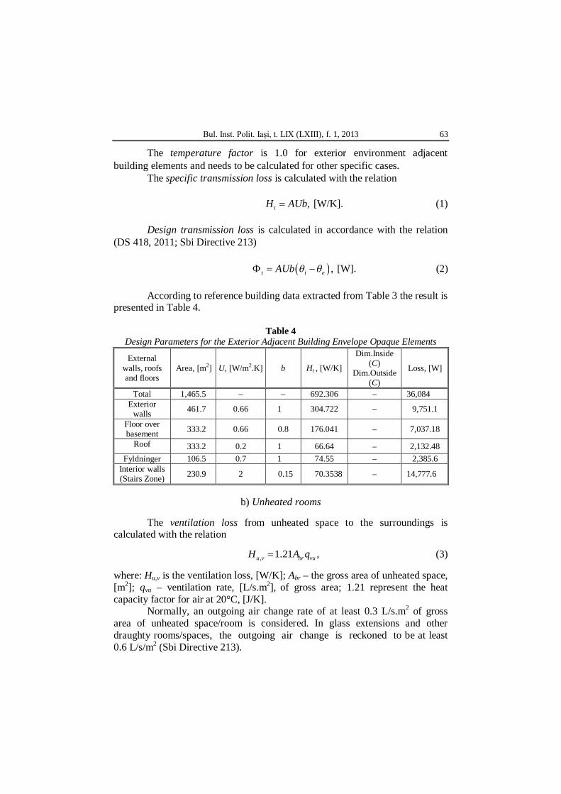
According to reference building data extracted from Table 3 the result is
presented in Table 4.
Table 4 Design Parameters for the Exterior Adjacent Building Envelope Opaque Elements
External walls, roofs and floors
Area, [m2] U, [W/m2.K] b Ht , [W/K]
Dim.Inside (C)
Dim.Outside (C)
Loss, [W]
Total 1,465.5 – – 692.306 – 36,084 Exterior
walls 461.7 0.66 1 304.722 – 9,751.1
Floor over basement 333.2 0.66 0.8 176.041 – 7,037.18
Roof 333.2 0.2 1 66.64 – 2,132.48 Fyldninger 106.5 0.7 1 74.55 – 2,385.6
Interior walls (Stairs Zone) 230.9 2 0.15 70.3538 – 14,777.6
b) Unheated rooms
The ventilation loss from unheated space to the surroundings is
calculated with the relation
, 1.21 ,u v br vuH A q (3)
where: Hu,v is the ventilation loss, [W/K]; Abr – the gross area of unheated space, [m2]; qvu – ventilation rate, [L/s.m2], of gross area; 1.21 represent the heat capacity factor for air at 20°C, [J/K].
Normally, an outgoing air change rate of at least 0.3 L/s.m2 of gross area of unheated space/room is considered. In glass extensions and other draughty rooms/spaces, the outgoing air change is reckoned to be at least 0.6 L/s/m2 (Sbi Directive 213).
64 Gabriel Teodoriu and Kirsten Engelund Thomsen
The temperature factor, b, is determined under stationary conditions, without heat gain in the unheated space. The temperature factor states how much lower the temperature is in the unheated rooms/spaces than the indoor air temperature, seen in relation to the difference between temperatures in the building and outside. The temperature factor is calculated as
,u
i u
HbH H
(4)
where: b is the temperature factor; Hi – the heat loss from the building to the unheated spaces/rooms, [W/K]; Hu – the heat loss from the unheated spaces to the surroundings, [W/K].
The temperature factor also indicates how much of the solar radiation in an unheated room/space will heat the conditioned space of the building.
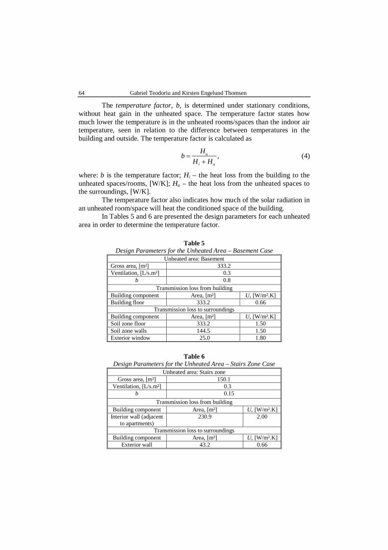
In Tables 5 and 6 are presented the design parameters for each unheated area in order to determine the temperature factor.
Table 5 Design Parameters for the Unheated Area – Basement Case
Unheated area: Basement Gross area, [m²] 333.2 Ventilation, [L/s.m²] 0.3
b 0.8 Transmission loss from building
Building component Area, [m²] U, [W/m².K] Building floor 333.2 0.66
Transmission loss to surroundings Building component Area, [m²] U, [W/m².K] Soil zone floor 333.2 1.50 Soil zone walls 144.5 1.50 Exterior window 25.0 1.80
Table 6
Design Parameters for the Unheated Area – Stairs Zone Case Unheated area: Stairs zone
Gross area, [m²] 150.1 Ventilation, [L/s.m²] 0.3
b 0.15 Transmission loss from building
Building component Area, [m²] U, [W/m².K] Interior wall (adjacent
to apartments) 230.9 2.00
Transmission loss to surroundings Building component Area, [m²] U, [W/m².K]
Exterior wall 43.2 0.66
Bul. Inst. Polit. Iaşi, t. LIX (LXIII), f. 1, 2013 65
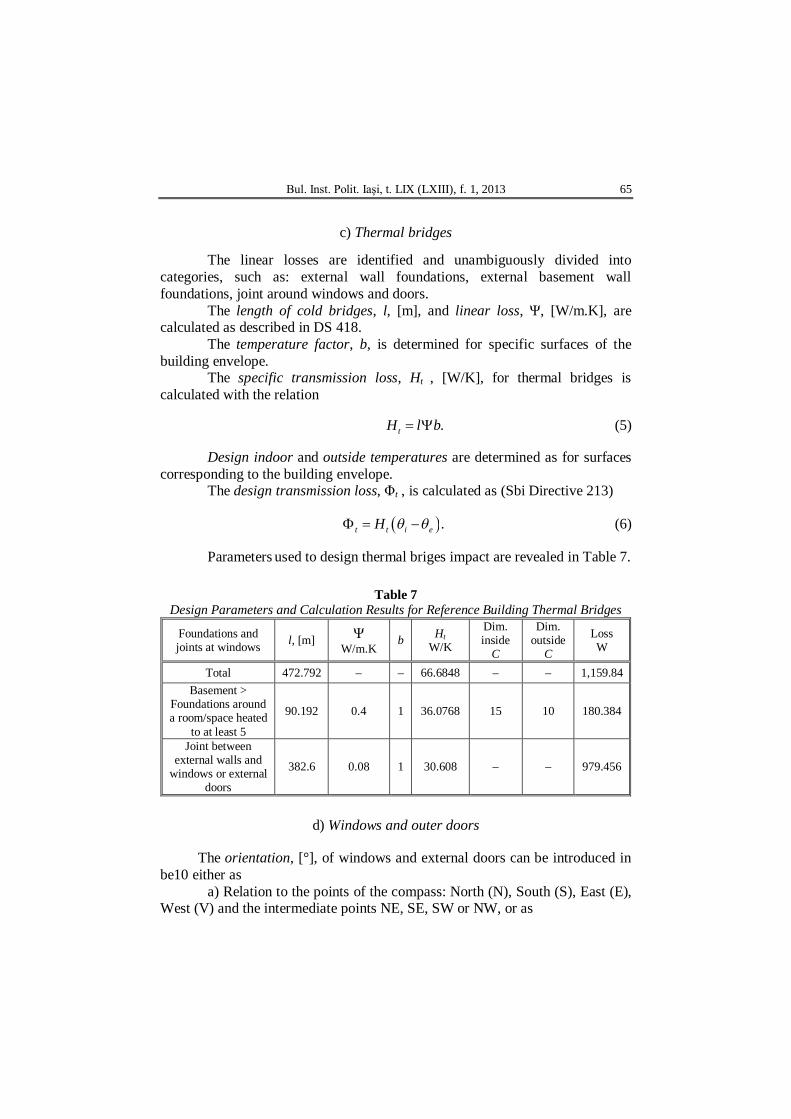
c) Thermal bridges
The linear losses are identified and unambiguously divided into
categories, such as: external wall foundations, external basement wall foundations, joint around windows and doors.
The length of cold bridges, l, [m], and linear loss, Ψ, [W/m.K], are calculated as described in DS 418.
The temperature factor, b, is determined for specific surfaces of the building envelope.
The specific transmission loss, Ht , [W/K], for thermal bridges is calculated with the relation
.tH l b (5) Design indoor and outside temperatures are determined as for surfaces
corresponding to the building envelope. The design transmission loss, Φt , is calculated as (Sbi Directive 213)
.t t i eH (6)
Parameters used to design thermal briges impact are revealed in Table 7.
Table 7 Design Parameters and Calculation Results for Reference Building Thermal Bridges
Foundations and joints at windows l, [m] Ψ
W/m.K b Ht
W/K
Dim. inside
C
Dim. outside
C
Loss W
Total 472.792 – – 66.6848 – – 1,159.84 Basement >
Foundations around a room/space heated
to at least 5
90.192 0.4 1 36.0768 15 10 180.384
Joint between external walls and
windows or external doors
382.6 0.08 1 30.608 – – 979.456
d) Windows and outer doors
The orientation, [°], of windows and external doors can be introduced in be10 either as
a) Relation to the points of the compass: North (N), South (S), East (E), West (V) and the intermediate points NE, SE, SW or NW, or as
66 Gabriel Teodoriu and Kirsten Engelund Thomsen
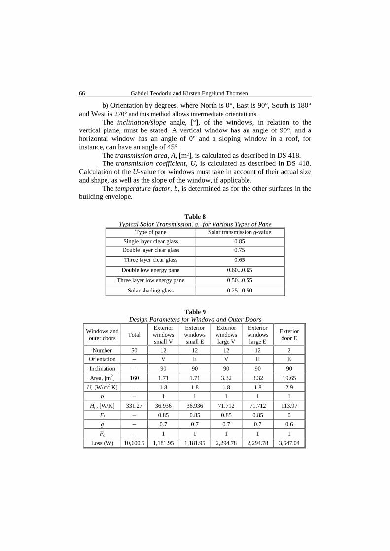
b) Orientation by degrees, where North is 0°, East is 90°, South is 180° and West is 270° and this method allows intermediate orientations.
The inclination/slope angle, [°], of the windows, in relation to the vertical plane, must be stated. A vertical window has an angle of 90°, and a horizontal window has an angle of 0° and a sloping window in a roof, for instance, can have an angle of 45°.
The transmission area, A, [m²], is calculated as described in DS 418. The transmission coefficient, U, is calculated as described in DS 418.
Calculation of the U-value for windows must take in account of their actual size and shape, as well as the slope of the window, if applicable.
The temperature factor, b, is determined as for the other surfaces in the building envelope.
Table 8 Typical Solar Transmission, g, for Various Types of Pane
Type of pane Solar transmission g-value Single layer clear glass 0.85 Double layer clear glass 0.75
Three layer clear glass 0.65
Double low energy pane 0.60...0.65
Three layer low energy pane 0.50...0.55
Solar shading glass 0.25...0.50
Table 9 Design Parameters for Windows and Outer Doors
Windows and outer doors Total
Exterior windows small V
Exterior windows small E
Exterior windows large V
Exterior windows large E
Exterior door E
Number 50 12 12 12 12 2 Orientation – V E V E E Inclination – 90 90 90 90 90 Area, [m2] 160 1.71 1.71 3.32 3.32 19.65
U, [W/m2.K] – 1.8 1.8 1.8 1.8 2.9 b – 1 1 1 1 1
Ht , [W/K] 331.27 36.936 36.936 71.712 71.712 113.97 Ff – 0.85 0.85 0.85 0.85 0 g – 0.7 0.7 0.7 0.7 0.6 Fc – 1 1 1 1 1
Loss (W) 10,600.5 1,181.95 1,181.95 2,294.78 2,294.78 3,647.04
Bul. Inst. Polit. Iaşi, t. LIX (LXIII), f. 1, 2013 67
The glass fraction, FF , represents the proportion of the total transmis-sion area filled by glass. The glass fraction is calculated for the windows or external doors concerned. For larger windows, the glass fraction is typically 0.5…0.8 (Sbi Directive 213).
The solar transmission of the panes, g-values, are considered as specified in Table 8.
The design parameters specific to the external windows and doors for the reference building are presented in Table 9.
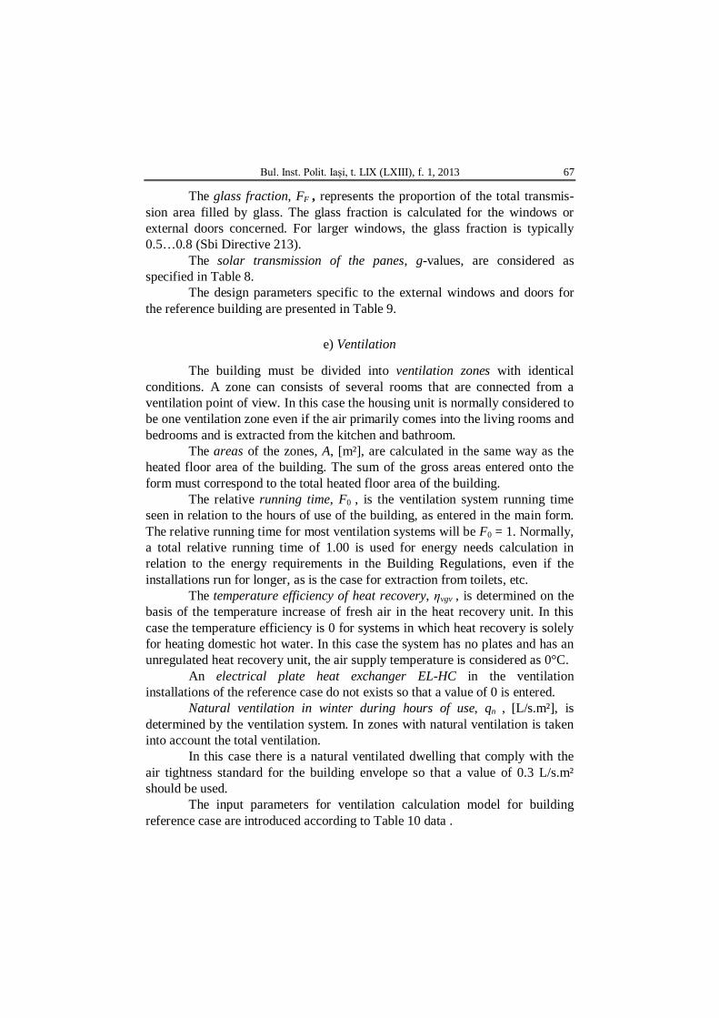
e) Ventilation
The building must be divided into ventilation zones with identical
conditions. A zone can consists of several rooms that are connected from a ventilation point of view. In this case the housing unit is normally considered to be one ventilation zone even if the air primarily comes into the living rooms and bedrooms and is extracted from the kitchen and bathroom.
The areas of the zones, A, [m²], are calculated in the same way as the heated floor area of the building. The sum of the gross areas entered onto the form must correspond to the total heated floor area of the building.
The relative running time, F0 , is the ventilation system running time seen in relation to the hours of use of the building, as entered in the main form. The relative running time for most ventilation systems will be F0 = 1. Normally, a total relative running time of 1.00 is used for energy needs calculation in relation to the energy requirements in the Building Regulations, even if the installations run for longer, as is the case for extraction from toilets, etc.
The temperature efficiency of heat recovery, ηvgv , is determined on the basis of the temperature increase of fresh air in the heat recovery unit. In this case the temperature efficiency is 0 for systems in which heat recovery is solely for heating domestic hot water. In this case the system has no plates and has an unregulated heat recovery unit, the air supply temperature is considered as 0°C.
An electrical plate heat exchanger EL-HC in the ventilation installations of the reference case do not exists so that a value of 0 is entered.
Natural ventilation in winter during hours of use, qn , [L/s.m²], is determined by the ventilation system. In zones with natural ventilation is taken into account the total ventilation.
In this case there is a natural ventilated dwelling that comply with the air tightness standard for the building envelope so that a value of 0.3 L/s.m² should be used.
The input parameters for ventilation calculation model for building reference case are introduced according to Table 10 data .
68 Gabriel Teodoriu and Kirsten Engelund Thomsen
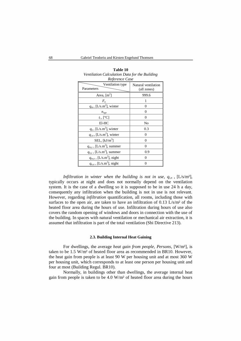
Table 10
Ventilation Calculation Data for the Building Reference Case
Ventilation type Parameters
Natural ventilation (all zones)
Area, [m2] 999.6 Fo 1
qm , [L/s.m2], winter 0 nvgv 0
ti , [°C] 0 El-HC No
qn , [L/s.m2], winter 0.3 qi,n , [L/s.m2], winter 0
SEL, [kJ/m3] 0 qm,s , [L/s.m2], summer 0 qn,s , [L/s.m2], summer 0.9 qm,n , [L/s.m2], night 0 qn,n , [L/s.m2], night 0
Infiltration in winter when the building is not in use, qi,n , [L/s/m²],
typically occurs at night and does not normally depend on the ventilation system. It is the case of a dwelling so it is supposed to be in use 24 h a day, consequently any infiltration when the building is not in use is not relevant. However, regarding infiltration quantification, all rooms, including those with surfaces to the open air, are taken to have an infiltration of 0.13 L/s/m² of the heated floor area during the hours of use. Infiltration during hours of use also covers the random opening of windows and doors in connection with the use of the building. In spaces with natural ventilation or mechanical air extraction, it is assumed that infiltration is part of the total ventilation (Sbi Directive 213).
2.3. Building Internal Heat Gaining
For dwellings, the average heat gain from people, Persons, [W/m²], is taken to be 1.5 W/m² of heated floor area as recommended in BR10. However, the heat gain from people is at least 90 W per housing unit and at most 360 W per housing unit, which corresponds to at least one person per housing unit and four at most (Building Regul. BR10).
Normally, in buildings other than dwellings, the average internal heat gain from people is taken to be 4.0 W/m² of heated floor area during the hours
Bul. Inst. Polit. Iaşi, t. LIX (LXIII), f. 1, 2013 69
of use of the building. As a matter of fact, the presence of people when the building is not in use is not to be taken into consideration.
If the internal heat gains from people in other types of buildings deviates significantly from the values above, the average internal heat gain for the building in the hours of use of the building can be determined from the actual conditions in the rooms/spaces, including, for instance, the number of people and their presence or absence.
In dwellings, the average heat gain from equipment, App., [W/m²], including lighting is taken to be 3.5 W/m² of heated floor area. However, the heat gain from the equipment for each dwelling/housing unit is taken to be at least 210 W and at most 840 W, corresponding to at least one person and at most four people in each housing unit.
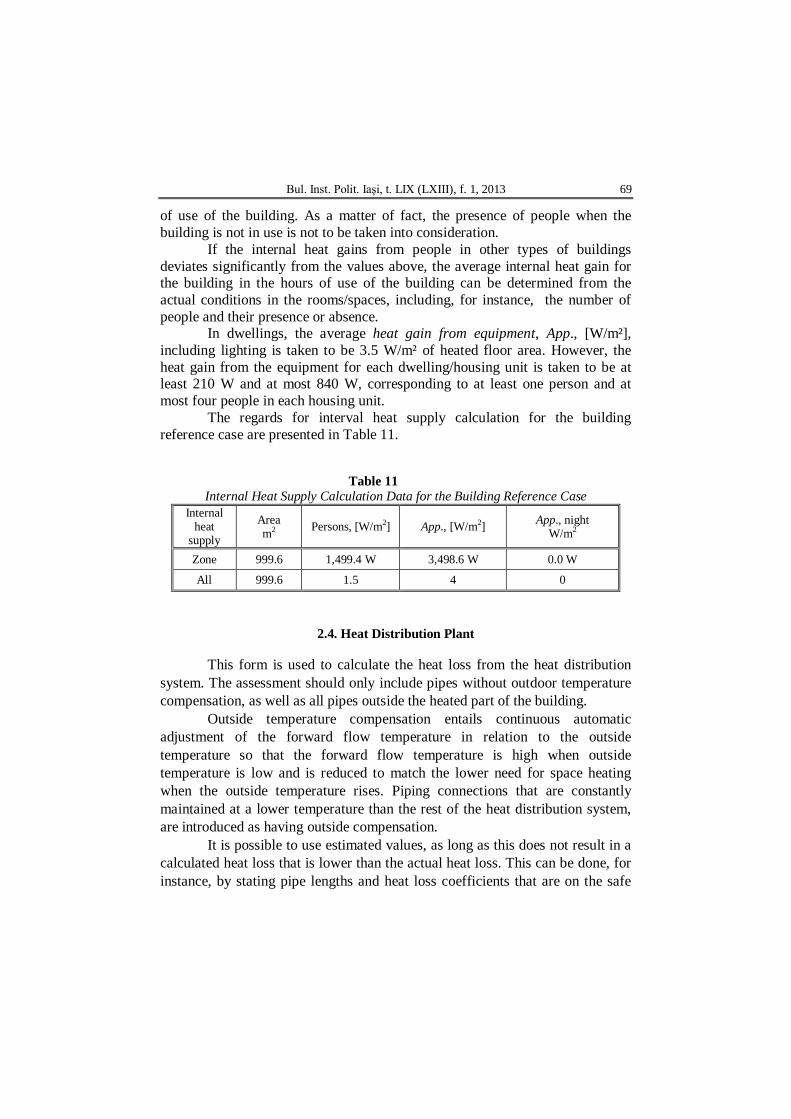
The regards for interval heat supply calculation for the building reference case are presented in Table 11.
Table 11 Internal Heat Supply Calculation Data for the Building Reference Case
Internal heat
supply
Area m2 Persons, [W/m2] App., [W/m2] App., night
W/m2
Zone 999.6 1,499.4 W 3,498.6 W 0.0 W
All 999.6 1.5 4 0
2.4. Heat Distribution Plant
This form is used to calculate the heat loss from the heat distribution system. The assessment should only include pipes without outdoor temperature compensation, as well as all pipes outside the heated part of the building.
Outside temperature compensation entails continuous automatic adjustment of the forward flow temperature in relation to the outside temperature so that the forward flow temperature is high when outside temperature is low and is reduced to match the lower need for space heating when the outside temperature rises. Piping connections that are constantly maintained at a lower temperature than the rest of the heat distribution system, are introduced as having outside compensation.
It is possible to use estimated values, as long as this does not result in a calculated heat loss that is lower than the actual heat loss. This can be done, for instance, by stating pipe lengths and heat loss coefficients that are on the safe
70 Gabriel Teodoriu and Kirsten Engelund Thomsen
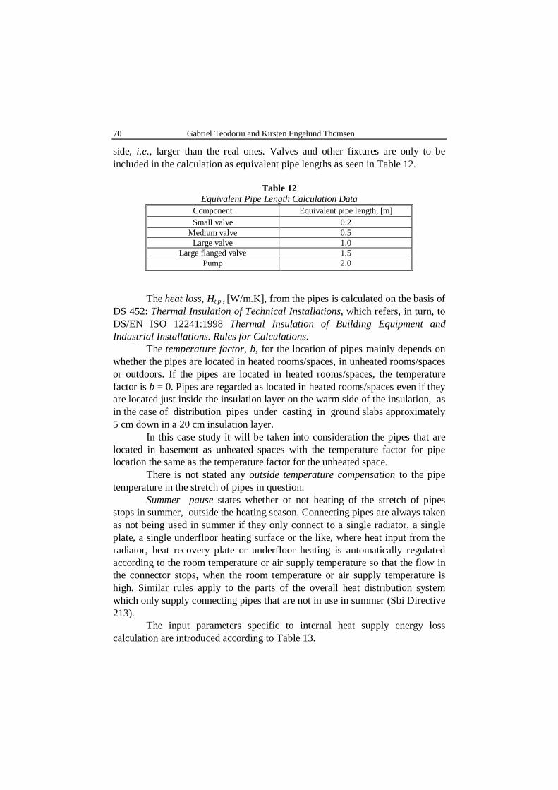
side, i.e., larger than the real ones. Valves and other fixtures are only to be included in the calculation as equivalent pipe lengths as seen in Table 12.
Table 12
Equivalent Pipe Length Calculation Data Component Equivalent pipe length, [m] Small valve 0.2
Medium valve 0.5 Large valve 1.0
Large flanged valve 1.5 Pump 2.0
The heat loss, Ht,p , [W/m.K], from the pipes is calculated on the basis of
DS 452: Thermal Insulation of Technical Installations, which refers, in turn, to DS/EN ISO 12241:1998 Thermal Insulation of Building Equipment and Industrial Installations. Rules for Calculations.
The temperature factor, b, for the location of pipes mainly depends on whether the pipes are located in heated rooms/spaces, in unheated rooms/spaces or outdoors. If the pipes are located in heated rooms/spaces, the temperature factor is b = 0. Pipes are regarded as located in heated rooms/spaces even if they are located just inside the insulation layer on the warm side of the insulation, as in the case of distribution pipes under casting in ground slabs approximately 5 cm down in a 20 cm insulation layer.
In this case study it will be taken into consideration the pipes that are located in basement as unheated spaces with the temperature factor for pipe location the same as the temperature factor for the unheated space.
There is not stated any outside temperature compensation to the pipe temperature in the stretch of pipes in question.
Summer pause states whether or not heating of the stretch of pipes stops in summer, outside the heating season. Connecting pipes are always taken as not being used in summer if they only connect to a single radiator, a single plate, a single underfloor heating surface or the like, where heat input from the radiator, heat recovery plate or underfloor heating is automatically regulated according to the room temperature or air supply temperature so that the flow in the connector stops, when the room temperature or air supply temperature is high. Similar rules apply to the parts of the overall heat distribution system which only supply connecting pipes that are not in use in summer (Sbi Directive 213).
The input parameters specific to internal heat supply energy loss calculation are introduced according to Table 13.
Bul. Inst. Polit. Iaşi, t. LIX (LXIII), f. 1, 2013 71
Table 13
Internal Heat Supply Calculation Data for the Building Reference Case
Pipe lengths in supply and return l, [m] Loss
W/m.K b Outdoor
compensation (Y/N)
Unused summer (Y/N)
Total 88.4 Pipes in the basement 88.4 0.54 0.8 N N
2.5. Domestic Hot Water
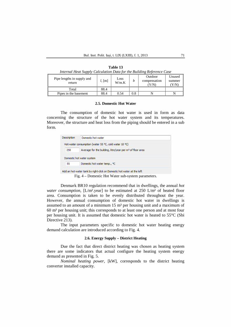
The consumption of domestic hot water is used in form as data concerning the structure of the hot water system and its temperatures. Moreover, the structure and heat loss from the piping should be entered in a sub form.
Fig. 4 – Domestic Hot Water sub-system parameters.
Denmark BR10 regulation recommend that in dwellings, the annual hot
water consumption, [L/m².year] to be estimated at 250 L/m² of heated floor area. Consumption is taken to be evenly distributed throughout the year. However, the annual consumption of domestic hot water in dwellings is assumed to an amount of a minimum 15 m³ per housing unit and a maximum of 60 m³ per housing unit; this corresponds to at least one person and at most four per housing unit. It is assumed that domestic hot water is heated to 55°C (Sbi Directive 213).
The input parameters specific to domestic hot water heating energy demand calculation are introduced according to Fig. 4.
2.6. Energy Supply – District Heating
Due the fact that direct district heating was chosen as heating system
there are some indicators that actual configure the heating system energy demand as presented in Fig. 5.
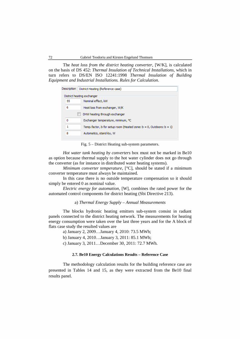
Nominal heating power, [kW], corresponds to the district heating converter installed capacity.
72 Gabriel Teodoriu and Kirsten Engelund Thomsen
The heat loss from the district heating converter, [W/K], is calculated on the basis of DS 452: Thermal Insulation of Technical Installations, which in turn refers to DS/EN ISO 12241:1998 Thermal Insulation of Building Equipment and Industrial Installations. Rules for Calculation.
Fig. 5 – District Heating sub-system parameters.
Hot water tank heating by converters box must not be marked in Be10
as option because thermal supply to the hot water cylinder does not go through the converter (as for instance in distributed water heating systems).
Minimum converter temperature, [°C], should be stated if a minimum converter temperature must always be maintained.
In this case there is no outside temperature compensation so it should simply be entered 0 as nominal value.
Electric energy for automation, [W], combines the rated power for the automated control components for district heating (Sbi Directive 213).
a) Thermal Energy Supply – Annual Measurements
The blocks hydronic heating emitters sub-system consist in radiant panels connected to the district heating network. The measurements for heating energy consumption were taken over the last three years and for the A block of flats case study the resulted values are
a) January 2, 2009…January 4, 2010: 73.5 MWh; b) January 4, 2010…January 3, 2011: 85.1 MWh; c) January 3, 2011…December 30, 2011: 72.7 MWh.
2.7. Be10 Energy Calculations Results – Reference Case
The methodology calculation results for the building reference case are
presented in Tables 14 and 15, as they were extracted from the Be10 final results panel.

Bul. Inst. Polit. Iaşi, t. LIX (LXIII), f. 1, 2013 73
Table 14
Be10 Results for Energy Demand Calculation Concerning Building Reference Case
The thermal energy and auxiliary electricity demand are converted into primary energy with a 2.5 standardized factor and the results can be consulted in Table 15.
Table 15
Framing Results in Accordance to BR10, BR15 and Future BR20 Standards Energy frame kW.h/m2.year Heat loss kW W/m2
BR 2010 147.2/54.3 Transmission loss 47.8 51.5
Low Energy Building 2015 124.3/31.1 Ventilation loss 10.8 11.6
Buildings 2020 92.3/20.0 Total 58.6 63.1

74 Gabriel Teodoriu and Kirsten Engelund Thomsen
The conclusion is that the existing block of flats has a primary energy demand that overrides up to three times the value provided in the Danish energy regulations so the requirement to take energy efficiency measures are entitled to apply.
3. Be10 Calculations – Renovation Case
The thermal rehabilitation program which concern this residential
building case study consists in adding a supplementary thermal insulation over the existing layers of 10 cm concrete +10 cm mineral wool insulation +14 cm concrete of exterior walls and also on socles and roofs/terraces, façade refurbishment with brick-tiles, windows replacement with three layers low-E glass thermopane with low U-values, etc., as presented in Tables 16 and 17.
Table 16
Characteristics of Renovated Building Envelope Elements
Block Element After renovation
Area m2
U-value W/m2.K
Length m
Ψ-value W/m.K
A
Exterior walls 485.9 0.15 – – Floor over basement 361.6 0.66 – –
Roof 0 0.09 – – Filling 98.7 0.11 – –
Windows, doors 204.7 0.8 – – Thermal bridges (wall, windows,
doors) – – 331.6 0.03
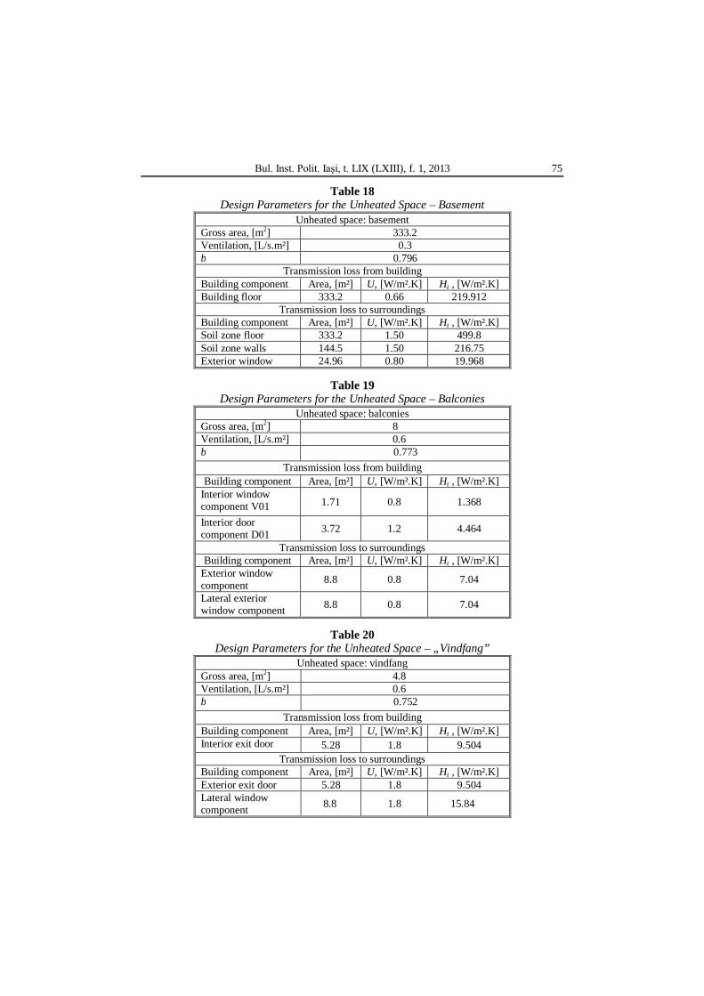
The characteristics of the unheated rooms specific to renovated case are
presented in Tables 18,…,24.
Table 17 Design Parameters for the Exterior Adjacent Building Envelope Opaque Elements
External walls, roofs and floors
Area m2
U
W/m2.K
b
Ht W/K
Dim.Inside/ Outside(°C) Dim.Outside
(°C)
Loss W
1,258.80 – – 289.61 – 10,704.00 Exterior
walls 485.90 0.15 1.00 72.89 – 2,332.32
Floor over basement 333.20 0.66 0.80 175.02 – 7,037.18
Roof 333.20 0.09 1.00 29.99 – 959.62 Fyldninger 106.50 0.11 1.00 11.72 – 374.88
Bul. Inst. Polit. Iaşi, t. LIX (LXIII), f. 1, 2013 75
Table 18 Design Parameters for the Unheated Space – Basement
Unheated space: basement Gross area, [m2] 333.2 Ventilation, [L/s.m²] 0.3 b 0.796
Transmission loss from building Building component Area, [m²] U, [W/m².K] Ht , [W/m².K] Building floor 333.2 0.66 219.912
Transmission loss to surroundings Building component Area, [m²] U, [W/m².K] Ht , [W/m².K] Soil zone floor 333.2 1.50 499.8 Soil zone walls 144.5 1.50 216.75 Exterior window 24.96 0.80 19.968
Table 19
Design Parameters for the Unheated Space – Balconies Unheated space: balconies
Gross area, [m2] 8 Ventilation, [L/s.m²] 0.6 b 0.773
Transmission loss from building Building component Area, [m²] U, [W/m².K] Ht , [W/m².K]
Interior window component V01 1.71 0.8 1.368
Interior door component D01 3.72 1.2 4.464
Transmission loss to surroundings Building component Area, [m²] U, [W/m².K] Ht , [W/m².K]
Exterior window component 8.8 0.8 7.04
Lateral exterior window component 8.8 0.8 7.04
Table 20
Design Parameters for the Unheated Space – „Vindfang” Unheated space: vindfang
Gross area, [m2] 4.8 Ventilation, [L/s.m²] 0.6 b 0.752
Transmission loss from building Building component Area, [m²] U, [W/m².K] Ht , [W/m².K] Interior exit door 5.28 1.8 9.504
Transmission loss to surroundings Building component Area, [m²] U, [W/m².K] Ht , [W/m².K] Exterior exit door 5.28 1.8 9.504 Lateral window component 8.8 1.8 15.84

76 Gabriel Teodoriu and Kirsten Engelund Thomsen
Table 21 Design Parameters of the Cold Bridges for Renovated Case
Foundations and joints at windows l, [m] Loss
W/m.K b Ht W/K
Dim Inside
Outside
Loss W
Total 472.792 – – 14.8777 – 598.188 Basement > Foundations
around a room/space heated to at least 5°C
90.192 0.08 0.8 5.74258 – 230.892
Joint between external walls and windows or
external doors 382.6 0.03 0.8 9.13514 –
367.296
Table 22
Design Parameters for the Exterior Windows and Doors For Renovated Case
Bul. Inst. Polit. Iaşi, t. LIX (LXIII), f. 1, 2013 77
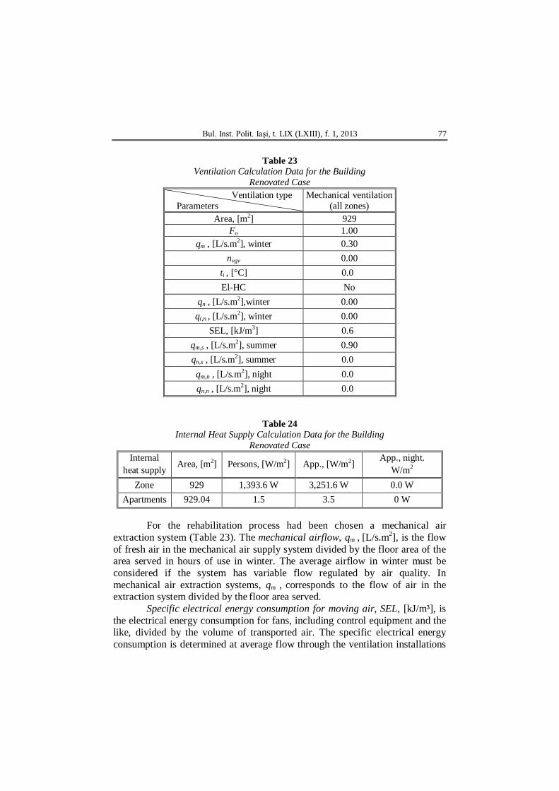
Table 23
Ventilation Calculation Data for the Building Renovated Case
Ventilation type Parameters
Mechanical ventilation (all zones)
Area, [m2] 929 Fo 1.00
qm , [L/s.m2], winter 0.30 nvgv 0.00
ti , [°C] 0.0 El-HC No
qn , [L/s.m2],winter 0.00 qi,n , [L/s.m2], winter 0.00
SEL, [kJ/m3] 0.6 qm,s , [L/s.m2], summer 0.90 qn,s , [L/s.m2], summer 0.0 qm,n , [L/s.m2], night 0.0 qn,n , [L/s.m2], night 0.0
Table 24 Internal Heat Supply Calculation Data for the Building
Renovated Case Internal
heat supply Area, [m2] Persons, [W/m2] App., [W/m2] App., night.
W/m2 Zone 929 1,393.6 W 3,251.6 W 0.0 W
Apartments 929.04 1.5 3.5 0 W
For the rehabilitation process had been chosen a mechanical air extraction system (Table 23). The mechanical airflow, qm , [L/s.m2], is the flow of fresh air in the mechanical air supply system divided by the floor area of the area served in hours of use in winter. The average airflow in winter must be considered if the system has variable flow regulated by air quality. In mechanical air extraction systems, qm , corresponds to the flow of air in the extraction system divided by the floor area served.
Specific electrical energy consumption for moving air, SEL, [kJ/m³], is the electrical energy consumption for fans, including control equipment and the like, divided by the volume of transported air. The specific electrical energy consumption is determined at average flow through the ventilation installations

78 Gabriel Teodoriu and Kirsten Engelund Thomsen
and must not exceed 1.2 kJ/m3. For installations with both air supply and extraction, the SEL is determined from the sum of the electrical energy consumption of the two fans (Sbi Directive 213).
For specific electrical energy consumption for air movement does exist SBI Guidelines 188: Ventilation Installations with Low Electrical Energy Consumption.
3.1. Be10 Results – Renovation Case
The Be10 final calculation results for the building renovated case are presented in Table 25.
Table 25
Be10 Results for Energy Demand Calculation Concerning Building Renovated Case
Bul. Inst. Polit. Iaşi, t. LIX (LXIII), f. 1, 2013 79
4. Conclusions
The case study is relevant to reveal the necessity and opportunity for
adapting the existing building stock to the new EU energy requirements and to integrate them in the 20/20/20 perspective.
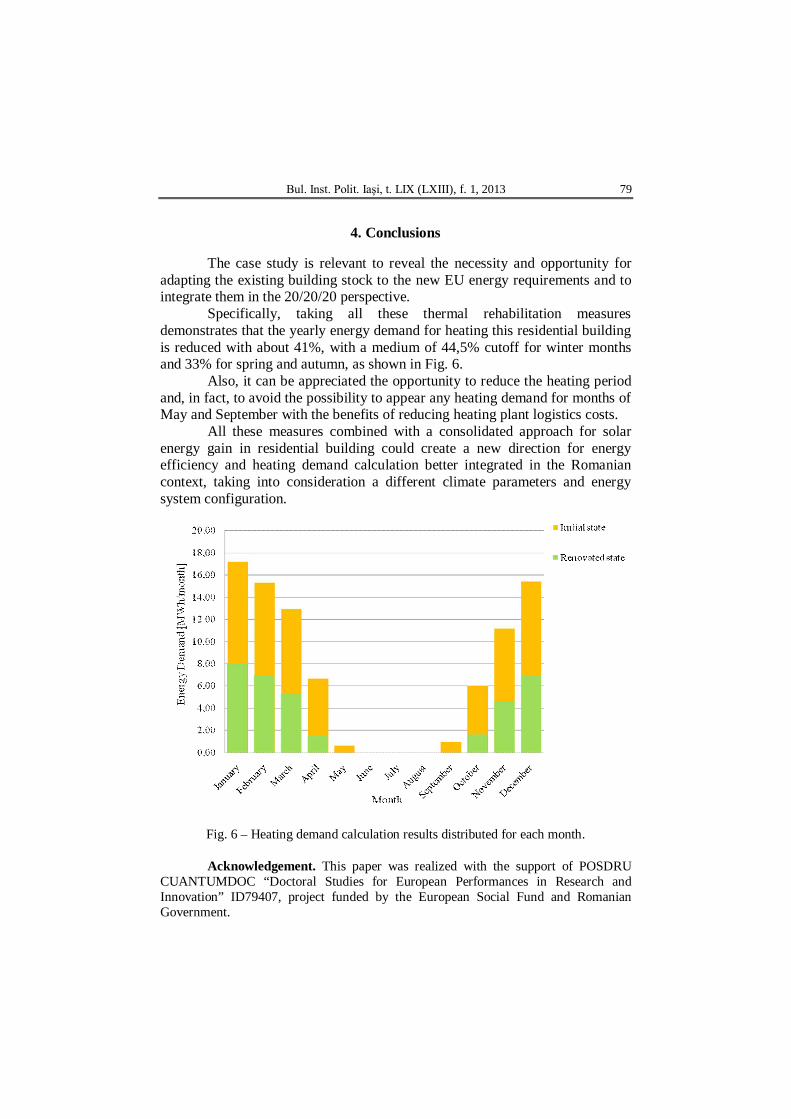
Specifically, taking all these thermal rehabilitation measures demonstrates that the yearly energy demand for heating this residential building is reduced with about 41%, with a medium of 44,5% cutoff for winter months and 33% for spring and autumn, as shown in Fig. 6.
Also, it can be appreciated the opportunity to reduce the heating period and, in fact, to avoid the possibility to appear any heating demand for months of May and September with the benefits of reducing heating plant logistics costs.
All these measures combined with a consolidated approach for solar energy gain in residential building could create a new direction for energy efficiency and heating demand calculation better integrated in the Romanian context, taking into consideration a different climate parameters and energy system configuration.
Fig. 6 – Heating demand calculation results distributed for each month. Acknowledgement. This paper was realized with the support of POSDRU
CUANTUMDOC “Doctoral Studies for European Performances in Research and Innovation” ID79407, project funded by the European Social Fund and Romanian Government.
80 Gabriel Teodoriu and Kirsten Engelund Thomsen
REFERENCES
Amann J.T., Valuation of Non-Energy Benefits to Determine Cost-Effectiveness of
Whole-House Retrofits Programs: A Literature Review. Amer. Council for an Energy-Efficient Econ., Washington DC, 2006.
Teodoriu G., Șerbănoiu I., Studiu comparativ privind stadiul programelor de eficienti-zare energetică a clădirilor de locuit în Danemarca și România. 6th AAEC National Conf., Craiova, Romania, October 26, 2012.
* *
* Calculation of Heat Loss from Buildings. DS 418:2011. *
* * Energy Demand of Building. Sbi Directive 213.
* *
* Building Regulation BR10 (English Version). Danish Ministry of Econ. a. Business Aff., Danish Enterpr. a. Constr. Auth.
STUDIU DE CAZ PRIVIND METODOLOGIA DE REABILITARE A UNUI BLOC
DE APARTAMENTE DIN DANEMARCA PRIN VALORIFICAREA PROGRAMULUI DE CALCUL AL NECESARULUI DE ENERGIE BE10
CONFORM NORMELOR BR10
(Rezumat) Se rezumă aspectele cheie ale unui studiu de caz cu privire la situaţia iniţială,
respectiv reabilitată, a unei clădiri de locuit situată într-un complex rezidenţial din Danemarca care a fost implicat în proiectul internaţional IEA Annex 56 ale cărui principale obiective, urmărite în acest articol, constau în selectarea unor studii de caz exemplificatoare în demersul încurajării factorilor de decizie pentru a reflecta asupra metodelor eficiente şi rentabile de reabilitare a clădirilor, sintetizarea beneficiilor suplimentare obţinute în procesul de renovare, determinarea opţiunilor cost-eficiente şi capacitatea de orientare către surse regenerabile de alimentare cu energie. În urma direcţiilor trasate prin metodologiile de profil emise de Comisia Europeană, studiul de caz urmăreşte să demonstreze beneficiile unui proces de reabilitare pentru o clădire conectată la un sistem de termoficare prin care să se sublinieze şi posibilitatea de adaptare la contextul românesc.