Embed Size (px)
Citation preview

(English) DM-M8050-05
Dealer's Manual
ROAD MTB Trekking
City Touring/ Comfort Bike
URBAN SPORT E-BIKE
DEORE XTM8050 series
DEORE XTRD-M8050FD-M8070SM-FD905SW-M8050SM-BTC1BT-DN110BM-DN100SC-MT800

2
CONTENTS
IMPORTANT NOTICE .............................................................................................. 4
TO ENSURE SAFETY ............................................................................................... 5
LIST OF TOOLS TO BE USED ................................................................................ 15
INSTALLATION ..................................................................................................... 17Electrical wiring diagram ...........................................................................................................................17
Installing the system information display .................................................................................................20
Installation of junction A ...........................................................................................................................22
Installation of the shifting switch .............................................................................................................23
Installation of the front derailleur ............................................................................................................24
Installation of the rear derailleur ..............................................................................................................31
Connection of the electric wires ...............................................................................................................33
Installation of the battery .........................................................................................................................37
Installation of the chain .............................................................................................................................47
HOW TO OPERATE .............................................................................................. 49Basic operations of the shifting switch .....................................................................................................49
Gear position control .................................................................................................................................50
Displaying and operating the system information display ......................................................................51
Error message .............................................................................................................................................57
About wireless functions ...........................................................................................................................58
ADJUSTMENT ...................................................................................................... 61Adjustment of the rear derailleur .............................................................................................................61
Adjustment of the front derailleur ...........................................................................................................66
Adjusting rear derailleur friction ..............................................................................................................73

3
CHARGING THE BATTERY .................................................................................... 76Names of parts ...........................................................................................................................................76
Charging the battery .................................................................................................................................78
When charging is not possible ..................................................................................................................80
CONNECTION AND COMMUNICATION WITH DEVICES ..................................... 83Settings customizable in E-TUBE PROJECT ...............................................................................................83
Connecting to a PC .....................................................................................................................................85
MAINTENANCE .................................................................................................... 89Replacing parts – shifting switch ...............................................................................................................89
Replacing parts – rear derailleur ...............................................................................................................89
Replacing rubber pad B .............................................................................................................................96
Disconnection of the electric wires ...........................................................................................................97

4
IMPORTANT NOTICE
IMPORTANT NOTICE
• This dealer's manual is intended primarily for use by professional bicycle mechanics. Users who are not professionally trained for bicycle assembly should not attempt to install the components themselves using the dealer's manuals. If any part of the information on the manual is unclear to you, do not proceed with the installation. Instead, contact your place of purchase or a local bicycle dealer for their assistance.
• Make sure to read all instruction manuals included with the product.
• Do not disassemble or modify the product other than as stated in the information contained in this dealer's manual.
• All dealer's manuals and instruction manuals can be viewed on-line on our website (http://si.shimano.com).
• Please observe the appropriate rules and regulations of the country, state or region in which you conduct your business as a dealer.
• The Bluetooth® word mark and logos are registered trademarks owned by the Bluetooth SIG, Inc. and any use of such marks by SHIMANO INC. is under license. Other trademarks and trade names are those of their respective owners.
For safety, be sure to read this dealer's manual thoroughly before use, and follow it for correct use.
The following instructions must be observed at all times in order to prevent personal injury and physical damage to equipment and surroundings.The instructions are classified according to the degree of danger or damage which may occur if the product is used incorrectly.
DANGER
Failure to follow the instructions will result in death or serious injury.
WARNING
Failure to follow the instructions could result in death or serious injury.
CAUTION
Failure to follow the instructions could cause personal injury or physical damage to equipment and surroundings.
5
TO ENSURE SAFETY
TO ENSURE SAFETY
DANGER
Be sure to also inform users of the following:
�Lithium ion battery Be sure to observe the following instructions in order to avoid burns or other injury from fluid leakage, overheating, fire, or explosion.
• Use the designated charger to charge the battery. If any non-specified items are used, fire, overheating or leakage may occur. • Do not heat the battery or throw it into fire. If this is not observed, fire or bursting may occur. • Do not deform, modify, disassemble or apply solder directly to the battery. Do not leave the battery in places which may exceed 60 °C in temperature, such as places which are exposed to direct sunlight inside vehicles on hot days or near stoves. If this is not observed, leakages, overheating or bursting may cause fire, burns, or other injuries. • Do not connect the (+) and (-) terminals with metallic objects. Do not carry or store the battery together with metallic objects such as necklaces or hairpins. If this is not observed, short-circuits, overheating, burns or other injury may occur. • If any liquid leaking from the battery gets into the eyes, immediately wash the affected area with clean water without rubbing the eyes, and then seek medical attention.
�Battery charger/Battery charger cord Be sure to observe the following instructions in order to avoid burns or other injury from fluid leakage, overheating, fire, or explosion.
• Do not get the charger wet or use it while it is wet, and do not touch or hold it with wet hands. If this is not observed, problems with operation or electric shocks may occur. • Do not cover the charger with cloths while it is in use. If this is not observed, heat may build up and the case may become deformed, or fire or overheating may occur. • Do not disassemble or modify the charger. If this is not observed, electric shocks or injury may occur. • Use the charger at the specified power supply voltage only. If a power supply voltage other than that specified is used, fire, explosions, smoke, overheating, electric shocks or burns may occur. • Do not touch metallic parts of the charger or the AC adapter if there is a lighting storm. If lightning strikes, electric shocks may occur.
SM-BCR2: Battery charger for SM-BTR2/BT-DN110 • Use an AC adapter with a USB port with a voltage of 5.0Vdc and with a current equal to or higher than 1.0Adc. If the one with a current lower than 1.0A is used, the AC adapter may heat up, potentially causing a fire, smoke, overheating, destruction, electric shock, or burns.

6
TO ENSURE SAFETY
WARNING
• Be sure to follow the instructions provided in the manuals when installing the product. It is recommended to use genuine Shimano parts only. If parts such as bolts and nuts become loose or damaged, the bicycle may suddenly fall over, which may cause serious injury. In addition, if adjustments are not carried out correctly, problems may occur, and the bicycle may suddenly fall over, which may cause serious injury.
• Be sure to wear safety glasses or goggles to protect your eyes while performing maintenance tasks such as replacing parts.
• After reading the dealer's manual thoroughly, keep it in a safe place for later reference.
Be sure to also inform users of the following: • Intervals between maintenance depend on the use and riding circumstances. Clean the chain with an appropriate chain cleaner regularly. Never use alkali based or acid based solvents, such as rust cleaners. If those solvents are used the chain might break and cause serious injury.
• When the shifting switch is operated, the powerful motor which drives the front or rear derailleur will operate to the shifting lever position without stopping, so be careful not to get your fingers caught.
• Check that the wheels are fastened securely before riding the bicycle. If the wheels are loose in any way, they may come off the bicycle and serious injury may result.
• Check the chain for any damage (deformation or crack), skipping, or other abnormalities such as unintended gear shifting. If any problems are found, consult a dealer or an agency. The chain may break, and you may fall.
• Be careful not to let the hemming of your clothes get caught in the chain while riding. Otherwise you may fall off the bicycle.

7
TO ENSURE SAFETY
�About the multi-shift function
• On this system, the multi-shift function can be configured using E-TUBE PROJECT. The gears will continue to shift when the shifting switch is pressed using the multi-shift function. Shifting speed setting for multi-shift can also be modified. When modifying the gear changing settings for multi-shift, carefully read "Settings customizable in E-TUBE PROJECT" in this dealer's manual.
• If crank revolutions are set to low under faster setting of the multi-shift shifting speed, the chain will be unable to follow the movement of the rear derailleur, possibly leading to issues such as the chain slipping over the tip of the cassette sprocket teeth, the cassette sprocket deforming, or the chain breaking.
Item Multi-shift speed Characteristics Usage notes Crank rotation speed when
operating multi-shift
Very fastHigh speed
Quick multi-shifting is possible
• The crank rotation speed can be adjusted quickly depending on changes in riding conditions.
• The speed can be adjusted quickly.
• Over-shifting occurs easily.
• If the rotation speed of the crank is low, the chain will be unable to follow the movement of the rear derailleur. The chain may therefore slip over the tip of the cassette sprocket teeth.
High crank rotation speed
Fast
Normal Default setting
Slow
Very slow Low speed Accurate multi-shifting is
possibleMulti-shifting takes some time
By default it is set to Normal. Fully understand the features of the multi-shift speed, and choose a multi-shift gear shifting setting according to the riding conditions (terrain, riding method, etc.).

8
TO ENSURE SAFETY
�Lithium ion battery
• Do not place the battery into fresh water or sea water, and do not allow the battery terminals to get wet. If this is not observed, fire, bursting or overheating may occur.
• Do not use the battery if it has any noticeable scratches or other external damage. If this is not observed, bursting, overheating or problems with operation may occur.
• Do not throw or subject the battery to strong shock. If this is not observed, bursting, overheating or problems with operation may occur.
• Do not use the battery if leakages, discoloration, deformation or any other abnormalities occur. If this is not observed, bursting, overheating or problems with operation may occur.
• If any leaked fluid gets on your skin or clothes, wash it off immediately with clean water. The leaked fluid may damage your skin.
• The operating temperature ranges for the battery are given below. Do not use the battery in temperatures outside these ranges. If the battery is used or stored in temperatures which are outside these ranges, fire, injury or problems with operation may occur. 1.During discharge: –10°C - 50°C 2.During charging: 0°C - 45°C
SM-BTR1: Lithium ion battery • If charging is not complete after 1.5 hours, stop charging. If this is not observed, fire, bursting or overheating may occur.
SM-BTR2/BT-DN110: Lithium ion battery • If the battery does not become fully charged after 4 hours, stop charging. If this is not observed, fire, bursting or overheating may occur.
�Battery charger/Battery charger cord
SM-BCR1: Battery charger for SM-BTR1
• Hold the power plug when connecting or disconnecting the plug. Failure to do so may cause a fire or electric shock.
• If the following occurs, stop using the device and contact a dealer. A fire or electric shock may occur. * If heat or acrid-smelling smoke is coming out from the power plug. * There may be a bad connection inside the power plug.
• Do not overload the electrical outlet with appliances beyond its rated capacity, and use only a 100 – 240V AC electrical outlet. If the electrical outlet is overloaded by connecting too many appliances using adapters, overheating resulting in fire may occur.
• Do not damage the power cord or power plug. (Do not damage, process, let near hot objects, bend, twist or pull them; do not place heavy objects on top or bundle them tightly.) If they are used while damaged, fire, electric shocks or short-circuits may occur.
• Do not use the charger with commercially-available electrical transformers designed for overseas use, as they may damage the charger.
• Always be sure to insert the power plug as far as it will go. If this is not observed, fire may occur.
SM-BCR2: Battery charger for SM-BTR2/BT-DN110
• Do not use any USB cable other than the USB cable which is supplied with the PC linkage device. This may cause a charging error, fire, or failure to connect to PC due to overheating.
• Do not connect the charger to PC when it is on standby. This may cause a PC failure depending on its specifications.
• When connecting or disconnecting the USB cable or the charger, be sure to hold the cable by the plug. Failure to do so may cause a fire or electric shock.
• If the following occurs, stop using the device and contact a dealer. A fire or electric shock may occur. * If heat or acrid-smelling smoke is coming out from the power plug. * There may be a bad connection inside the power plug.
• If it thunders while charging with an AC adapter with a USB port, do not touch the device, bicycle, or the AC adapter. If lightning strikes, electric shocks may occur.
• Use an AC adapter with a USB port with a voltage of 5.0Vdc and with a current equal to or higher than 1.0Adc. If the one with a current lower than 1.0Adc is used, a charge error may occur or the AC adapter may heat up, leading to a fire.
• Do not use a USB hub when connecting the cable to a computer USB port. This may cause a charging error or fire due to overheating.
• Be careful not to damage the charging cable. (Do not damage, process, let near hot objects, bend, twist or pull them; do not place heavy objects on top or bundle them tightly.) If they are used while damaged, fire, electric shocks or short-circuits may occur.

9
TO ENSURE SAFETY
�Brake • Each bicycle may handle slightly differently depending on the model. Therefore, be sure to learn the proper braking technique (including brake lever pressure and bicycle control characteristics) and operation of your bicycle. Improper use of your bicycle's brake system may result in a loss of control or a fall, which could lead to severe injury. For proper operation, consult a professional bicycle dealer or the bicycle's owner's manual. It is also important to practice riding and braking, etc. • If the front brake is applied too strongly, the wheel may lock and the bicycle may fall forward, and serious injury may result. • Always make sure that the front and rear brakes are working correctly before riding the bicycle. • The required braking distance will be longer during wet weather. Reduce your speed and apply the brakes early and gently. • If the road surface is wet, the tires will skid more easily. If the tires skid, you may fall off the bicycle; therefore, to avoid this, reduce your speed and apply the brakes early and gently.
CAUTION
Be sure to also inform users of the following:
�Lithium ion battery • Store the battery in a safe place away from the reach of infants and pets.
SM-BTR1: Lithium ion battery • When you do not use the battery for a long period, remove and charge the battery before storage.
SM-BTR2/BT-DN110: Lithium ion battery • When you do not use the battery for a long period, charge the battery before storage.
�Battery charger/Battery charger cord
SM-BCR2: Battery charger for SM-BTR2/BT-DN110
• The charging cable cannot be removed.

10
TO ENSURE SAFETY
NOTE
Be sure to also inform users of the following:
• Be careful not to get water into the terminal.
• Be sure to attach dummy plugs to any unused terminals. If water gets into any of the components, operating problems or rusting may result.
• Be sure to rotate the crank when carrying out switch operations which are related to gear shifting.
• Do not keep connecting and disconnecting the small waterproof connector. The waterproof section or the connecting section may become worn or deformed, and the function may be affected.
• The components are designed to be fully waterproofed to withstand wet weather riding conditions; however, do not deliberately place them into water.
• Do not clean the bicycle with a high-pressure wash. Moreover, do not place any components in water. If water gets into any of the components, operating problems or rusting may result.
• Handle the product carefully, and avoid subjecting it to any strong shocks. The internal battery may be damaged. If the product has been subjected to a shock, consult a dealer.
• Do not use thinners or similar substances to clean the products. Such substances may damage the surfaces.
• If gear shifting operations do not feel smooth, wash the derailleur and lubricate all moving parts.
• Contact the place of purchase for updates of the component software. The most up-to-date information is available on the Shimano website.
• Products are not guaranteed against natural wear and deterioration from normal use and aging.
• For maximum performance we highly recommend Shimano lubricants and maintenance products.
�Lithium ion battery
• Lithium-ion batteries are recyclable, valuable resources. For information on used batteries, contact the place of purchase or a bicycle dealer.
• Charging can be carried out at any time regardless of the amount of charge remaining. Always be sure to use the special battery charger to charge the battery until it is fully recharged.
• The battery is not fully charged at the time of purchase. Before riding, be sure to fully charge the battery.
• If the battery has become completely empty, charge it as soon as possible. If you leave the battery without charging it, it will cause the battery to deteriorate.
• The battery is an exhaustible item. The battery will gradually lose its capacity to charging after repeated use. If the length of time that the battery can be used becomes extremely short, it has probably reached the end of its life, and so you will need to purchase a new battery.
• The life of the battery will vary depending on factors such as the storage method, the usage conditions, the surrounding environment and the characteristics of the individual battery pack.
• If storing the battery away for a long period, remove it when the battery level is 50% or higher or when the green indicator is illuminating in order to prolong its useful life; and it is recommended that you charge the battery about every six months.
• If the storage temperature is high, the performance of the battery is reduced, and its useable time will be shorter. When you use the battery after a long storage period, store the battery indoors where the battery will not be exposed to direct sunlight or rain.
• If the ambient temperature is low, the battery's usable time will be shorter.
SM-BTR1: Lithium ion battery
• When storing the battery away, remove the battery from the bicycle and install the terminal cover first.
• The charging time is approximately 1.5 hours. (Note that the actual time will vary depending on the remaining battery charge.)
• If the battery feels difficult to insert or remove, apply specified grease (premium grease) to the part that touches the O-ring at the side.
SM-BTR2/BT-DN110: Lithium ion battery • After removing the battery from the bicycle for storage, install a dummy plug. • The charging time of an AC adapter with a USB port is about 1.5 hours, and that of computer USB port type about 3 hours. (Note that the actual time will vary depending on the amount of charge remaining in the battery. Depending on the specifications of the AC adapter, recharging via the AC adapter may require as much time (about 3 hours) as recharging via PC.)

11
TO ENSURE SAFETY
�Battery charger/Battery charger cord • Use this instrument under the direction of a safety supervisor or the direction for use. Do not allow physically, sensory, or mentally impaired persons, inexperienced persons, or persons with no required knowledge, including children, to use this product. • Do not allow children to play near the product.
Disposal information for countries outside the European Union
This symbol is only valid within the European Union.
For information on used batteries, contact the place of purchase or a bicycle dealer.
• Charge the battery indoors to avoid exposure to rain or wind.
• Do not use outdoors or in environments with high humidity.
• Do not place the battery charger on dusty floors when using it.
• Place the battery charger on a stable surface such as a table when using it.
• Do not place any objects on top of the battery charger or its cable.
• Do not bundle the cables.
• Do not hold the battery charger by the cables when carrying it.
• Do not apply excessive tension to the cables.
• Do not wash the battery charger or wipe it using detergents.
SM-BCR2: Battery charger for SM-BTR2/BT-DN110
• Connect the PC linkage device directly to a computer, without using an intermediate device such as a USB hub.
• Do not ride the bicycle while the PC linkage device and cable are still connected to it.
• Do not connect two or more of the same units to the same connection point. If this is not done, the units may not operate correctly.
• Do not connect or disconnect units again while unit recognition is in progress or after recognition is complete. If this is not done, the units may not operate correctly. Check the procedures which are given in the user's manual for the E-TUBE PROJECT when connecting and disconnecting units.
• The tightness of the PC link cable will tend to drop after repeated connections and disconnections. If this happens, replace the cable.
• Do not connect two or more PC linkage device at the same time. If two or more PC linkage device units are connected, they will not operate correctly. In addition, the PC may need to be restarted if operating errors occur.
• PC linkage devices cannot be used while the charger is connected.
�Front derailleur • Make sure that the plug cover is attached to the terminal when using the product.
�Rear derailleur
• Be sure to check that the plate body cover and cap are installed before riding the bicycle.
• Make sure that the plug cover is attached to the terminal when using the product.
• If gear shifting operations do not feel smooth, wash the derailleur and lubricate all moving parts.
• If the chain keeps skipping, ask the place of purchase to replace the chainrings, sprockets and/or the chain.
• If there is a large gap in the pulleys which causes a lot of noise, ask the place of purchase to replace the pulleys.
• The gears should be periodically washed with a neutral detergent. In addition, cleaning the chain with neutral detergent and lubricating it can be an effective way of extending the life of the gears and the chain.
• If the amount of looseness in the links is so great that adjustment is not possible, you should replace the derailleur.

12
TO ENSURE SAFETY
For Installation to the Bicycle, and Maintenance:
• Be sure to attach dummy plugs to any unused terminals.
• Be sure to use Shimano original tool (TL-EW02) to remove the electric wires.
• The motors of the motor unit cannot be repaired.
• Contact Shimano for information regarding the shipment of the battery charger to South Korea and Malaysia.
• Use an electric wire which still has some length to spare even when the handlebars are turned all the way to both sides. Furthermore, check that the shifting lever does not touch the bicycle frame when the handlebars are turned all the way.
• Use the specified cable and cable guide for smooth operation.
• When replacing the brake oil, be careful not to let the oil splash onto the system information display. This may damage the product.
�Electric wires/Electric wire covers
• Secure the electric wires with a zip tie so that they do not interfere with the chainrings, sprockets or tires.
• The strength of the adhesive is fairly weak to prevent the paint on the frame from being peeled off when removing the electric wire cover, such as when replacing the electric wires. If the electric wire cover is peeled off, replace it with a new one. When removing the electric wire cover, do not peel it off too vigorously. If so, the paint on the frame will peel off, too.
• Do not remove the wire holders which are attached to the built-in type electric wires (EW-SD50-I). The wire holders prevent the electric wires from moving inside the frame.
• When installing to the bicycle, do not forcibly bend the electric wire plug. It may result in a poor contact.
�Shifting switch
• Dummy plugs are installed at the time of shipment from the factory. Do not remove them except when necessary.
• When routing the electric wires, take care to ensure that they do not interfere with the brake levers.
�Rear derailleur
• Always be sure to adjust the top adjustment bolt and the low adjustment bolt according to the instructions given in the adjustment section. If these bolts are not adjusted, the chain may become clamped between the spokes and the largest sprocket and the wheel may lock, or the chain may slip onto the small sprocket.
• Periodically clean the derailleur and lubricate all moving parts (mechanism and pulleys).
• If gear shifting adjustments cannot be carried out, check the degree of parallel of the rear fork ends.
• The pulley has an arrow on it to indicate the direction of rotation. Make sure that the arrow points in the direction of movement of the chain.
The actual product may differ from the illustration because this manual is intended mainly to explain the procedures for using the product.

13
TO ENSURE SAFETY
For Installation to the Bicycle, and Maintenance:
�Notes on reinstalling and replacing components • When the product is reassembled or replaced, it is automatically recognized by the system to allow operation according to the settings. • If the system does not operate after reassembly and replacement, follow the system power reset procedure below to check the operation. • If the component configuration changes or malfunction is observed, use the E-TUBE PROJECT software to update the firmware of each component to the latest version and perform a check again. Also make sure that the E-TUBE PROJECT software is the latest version. If the software is not the latest version, the component compatibility or the product functions may not be available.
Be sure to also inform users of the following:
�About used batteries • Lithium-ion batteries are recyclable, valuable resources. For information on used batteries, contact the place of purchase or a bicycle dealer.
�About system power reset
• When the system fails to operate, it may be recovered by resetting the system power.
• After the battery is removed, about one minute is usually required for the system power to reset.
In the case of using SM-BTR1 • Remove the battery from the battery mount. After about one minute, install the battery.
In the case of using SM-BTR2/BT-DN110 • Disconnect the plug from SM-BTR2/BT-DN110. After about one minute, insert the plug.
�Connection and communication with PC • PC linkage devices can be used to connect a PC to the bicycle (system or components), and an E-TUBE PROJECT can be used to carry out tasks such as customizing single components or the whole system and updating their firmware. If your versions of E-TUBE PROJECT software and firmware for each component are not up to date there could be problems operating the bicycle. Check the software version and update it to the latest one.
PC linkage device E-TUBE PROJECT Firmware
SM-BMR2/SM-BTR2
SM-PCE1/SM-BCR2 Version 3.0.0 or later
Version 3.0.0 or later
BT-DN110/BM-DN100Version 4.0.0 or later
* Pre-installed firmware is version 4.0.0.
�Connection and communication with smartphone or tablet
• It is possible to customize single components or the system, and update firmware, using E-TUBE PROJECT for smartphones/tablets after connecting the bicycle (system or components) to a smartphone or tablet via Bluetooth LE.
• E-TUBE PROJECT: app for smartphones/tablets
• Firmware: software inside each component
• Disconnect Bluetooth LE when not using E-TUBE PROJECT for smartphones/tablets. Using the system information display without disconnecting Bluetooth LE may result in high battery power consumption.
About compatibility with E-TUBE PROJECT • For details on compatibility with E-TUBE PROJECT, refer to the following website. (http://e-tubeproject.shimano.com/guide/#guide_list)

LIST OF TOOLS TO BE USED

15
LIST OF TOOLS TO BE USED
LIST OF TOOLS TO BE USED
The following tools are needed for installation, adjustment, and maintenance purposes.
Tool Tool Tool
2mm hexagon wrench 5mm hexagon wrench TL-EW02
2.5mm hexagon wrench Screwdriver[#2] TL-FDM905
3mm hexagon wrench Hexalobular[#8] Snap ring pliers
4mm hexagon wrench Hexalobular[#30]

INSTALLATION

17
INSTALLATION
Electrical wiring diagram
INSTALLATION
� Electrical wiring diagram
The connections shown below are only examples. The wiring method may differ depending on the type of frame. For details, contact a manufacturer of completed bicycles.
External battery type (without suspension connection/SM-BTC1)
[b]
(F)(E)[a](D)(C)
[c]
(B)(A)
[d]
[e]
(A) System information display/junction A
(B) Shifting switch
(C) Rear derailleur
(D) Front derailleur
(E) Battery case SM-BTC1
(F) Battery SM-BTR2/BT-DN110
TECH TIPS
Cable length (EW-SD50)[a] ≤ 300mm[b] ≤ 1000mm[c] ≤ 1200mm[d] ≤ 300mm[e] ≤ 300mm
External battery type (without suspension connection/SM-JC40)
[f]
[d]
[e]
[a]
[c]
[b]
(B)(A)
(C)
(A) Battery mount SM-BMR2/BM-DN100
(B) Battery SM-BTR1
(C) Junction B SM-JC40
TECH TIPS
Cable length (EW-SD50)[a] + [b] ≤ 900mm[a] + [c] ≤ 1100mm[d] ≤ 1400mm[e] ≤ 500mm[f] ≤ 500mm
18
INSTALLATION
Electrical wiring diagram
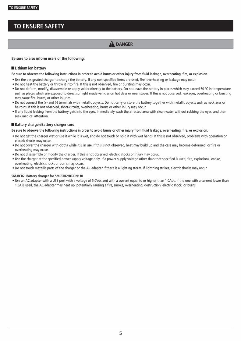
External battery type (with suspension connection/SM-BTC1)
[f]
(C)(B)(A) (E)(D)
[h]
[d]
[e]
[g]
[b]
[a]
[c]
(A) Battery case SM-BTC1
(B) Battery SM-BTR2/BT-DN110
(C) Rear suspension motor unit
(D) Front suspension motor unit
(E) Suspension lock switch
TECH TIPS
Cable length (EW-SD50)[a] ≤ 300mm[b] ≤ 1000mm[c] ≤ 1200mm[d] ≤ 300mm[e] ≤ 300mm[f] ≤ 1000mm[g] ≤ 1000mm[h] ≤ 600mm
External battery type (with suspension connection/SM-JC41)
(B) [h]
[a]
(C)(A)
[j]
[g]
[f]
[c]
[e]
[b]
[d]
[i]
(A) Battery mount SM-BMR2/BM-DN100
(B) Battery SM-BTR1
(C) Junction B SM-JC41
TECH TIPS
Cable length (EW-SD50)[a] + [b] ≤ 1500mm[a] + [c] ≤ 1700mm[d] ≤ 150mm[e] ≤ 1200mm[f] ≤ 250mm[g] ≤ 250mm[h] ≤ 1500mm[i] ≤ 1000mm[j] ≤ 600mm

19
INSTALLATION
Electrical wiring diagram
Built-in battery type (seat post type) without suspension connection
[a]
(B)[c]
[d]
[e] [f]
(A)
[b]
(A) Battery SM-BTR2/BT-DN110
(B) Junction B SM-JC41
TECH TIPS
Cable length (EW-SD50)[a] ≤ 1000mm[b] ≤ 500mm[c] ≤ 800mm[d] ≤ 1400mm[e] ≤ 250mm[f] ≤ 250mm
Built-in battery type (seat post type)
[a] [h]
(B)
[j]
[f] [g]
[c]
[e]
(A)
[b]
[d]
[i]
(A) Battery SM-BTR2/BT-DN110
(B) Junction B SM-JC41
TECH TIPS
Cable length (EW-SD50)[a] ≤ 1000mm[b] ≤ 500mm[c] ≤ 800mm[d] ≤ 150mm[e] ≤ 1200mm[f] ≤ 250mm[g] ≤ 250mm[h] ≤ 1500mm[i] ≤ 1000mm[j] ≤ 600mm

20
INSTALLATION
Installing the system information display
Built-in battery type (head tube type)
[b]
[h][e][f]
[k]
[d]
[i]
[j][a]
(A)
[g]
(B)
[c]
(A) Battery SM-BTR2/BT-DN110
(B) Junction B SM-JC41
TECH TIPS
Cable length (EW-SD50)[a] ≤ 150mm[b] ≤ 1400mm[c] ≤ 500mm[d] ≤ 800mm[e] ≤ 150mm[f] ≤ 400mm[g] ≤ 750mm[h] ≤ 250mm[i] ≤ 150mm[j] ≤ 600mm[k] ≤ 800mm
� Installing the system information display
Install the system information display or junction A first.
Replacing the clamp band
(A) (B)
Remove the case mounting bolt with a 2.5mm hexagon wrench and replace the clamp band.
(A) Case mounting bolt
(B) Clamp band
Tightening torque
0.6 N·m
NOTE
If using a handlebar with a thick diameter, reinstall it using the included Ø35mm clamp band.
21
INSTALLATION
Installing the system information display
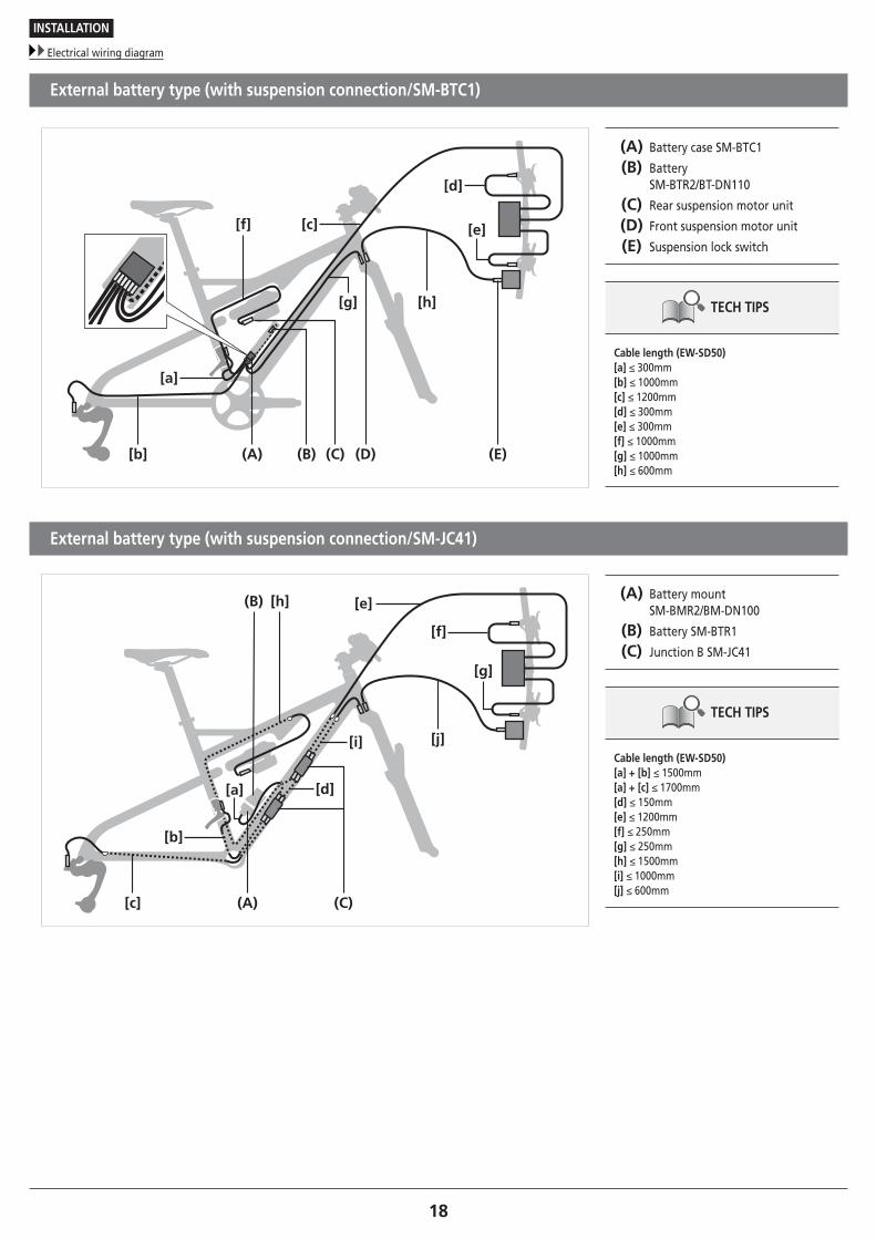
Installing to the handlebar
1
(A)
(B)
Insert the clamp band of the system information display into the handlebar.
(A) Clamp band
(B) System information display
2
(A)
Adjust the angle of the system information display so that it is easy to see, and then use a 3mm hexagon wrench to tighten the clamp bolt.
(A) Clamp bolt
Tightening torque
0.8 N·m
NOTE
Recommended installation angle of the information display: The angle of the display is between 15° to 35° to the horizontal
15°
35°

22
INSTALLATION
Installation of junction A
� Installation of junction A
1
(A)
(B)
(C)
Attach to the stem using the band and hook included with SM-EW90.
(A) Band
(B) Stem
(C) Hook
NOTE
Synchronized shift requires SC-MT800.
2
Adjust the length of the band according to the thickness of the stem.
Hook the band on the hook and wind it around the stem.
Pull on the band and make sure it is fi rmly attached.
3
(A)
Finished image
Slide junction A of SM-EW90 into the rail section of the hook to install it.
(A) SM-EW90 Junction A
TECH TIPS
RemovalPull up the release lever to slide junction A in the direction of the arrow for removal. Forcibly pulling up the release lever may break the lever.
Release lever

23
INSTALLATION
Installation of the shifting switch
� Installation of the shifting switch
The illustration shows the right-side lever.
1
(A) (B) Pass the handlebar through the shifting switch.
(A) Handlebar
(B) Shifting switch
TECH TIPS
Applicable handlebars: Ø22.2mm – Ø22.5mm
2
(A)
Adjust the attachment position and angle, and then use a 3mm hexagon wrench to tighten the clamp bolt.
(A) Clamp bolt
Tightening torque
2 - 2.2 N·m
NOTE
Attach the lever in a position where it will not touch the brake lever when pushed all the way in.
3
[X] [Y] (A)
Adjust the positions of lever [X] and lever [Y].
Loosen the lever fixing bolt using an 2mm hexagon wrench, and adjust the lever's position so that it is easy to push.
After determining the position, tighten to the designated torque.
(A) Lever fixing bolt
Tightening torque
0.5 - 0.7 N·m

24
INSTALLATION
Installation of the front derailleur
� Installation of the front derailleur
Types of adapters
There are four types of front derailleur adapters. Choose one according to the shape of the frame.
Type D Type E
High clamp Low clamp

25
INSTALLATION
Installation of the front derailleur
Installing the adapter
1
(A)
(B)
Slide the adapter onto the front derailleur and insert it.
(A) Adapter
(B) Front derailleur
2 (A)
Install the bracket mounting bolt at the position specified in the illustration, and tighten it with a 4mm hexagon wrench.
(A) Bracket mounting bolt
Tightening torque
5 - 7 N·m
TECH TIPS
• Although the illustration shows a type D adapter, the installation method is the same for all adapters.
• When replacing, reverse the procedure.

26
INSTALLATION
Installation of the front derailleur
Installation on rear suspension types
NOTE
When installing components to a carbon frame/handlebar, check the tightening torque recommended by the carbon frame or component manufacturer to avoid carbon material damage due to excessive tightening or insufficient component holding force resulting from insufficient tightening torque.
TECH TIPS
Adjust so that there is a clearance of 1 – 3mm between the chain guide outer plate and the largest chainring. (Common to all types)
• Bicycles with rear suspensions may be positioned differently when a rider is off the bicycle and on the bicycle. By referring to the illustration, perform installation and SIS adjustment while seated on the bicycle. Also, before riding the bicycle, make sure there is no interference between the front derailleur and the front chainring when the rear suspension is stroked.

27
INSTALLATION
Installation of the front derailleur
Band type
1
(A)
(z)Install the front derailleur to the frame.
Temporarily fix the clamp bolt with a 4mm hexagon wrench.
(z) 4mm hexagon wrench
(A) Clamp bolt
2
(B)
(A)
(z)
Position the front derailleur so that the flat part of the chain guide outer plate is directly above and parallel to the largest chainring.
Check that the distance from the tip of the teeth of the largest chainring is 1 to 3mm.
After adjusting the position, tighten the clamp bolt to the designated torque.
(z) 1 - 3mm
(A) Chain guide outer plate
(B) Largest chainring
Tightening torque
5 - 7 N·m
NOTE
Make sure not to position the chain guide as shown in the illustration.

28
INSTALLATION
Installation of the front derailleur
To be continued on next page
Type E
1
(A) (C)(B) Install the front derailleur with bottom bracket mount fixing bolts.
Temporarily fix the bottom bracket mount fixing bolt.
Fixing position varies depending on the number of gear teeth used.
See below for the fixing position.
(A) Bottom bracket mount
(B) Adapter
(C) Bottom bracket mount fixing bolt
NOTE
Shimano does not provide the bottom bracket mount fixing bolts.
Fixing position
(A) (B)
(C)
(D)
(A) Double: Largest chainring 38T
(B) Double: Largest chainring 36T
(C) Double: Largest chainring 34T

29
INSTALLATION
Installation of the front derailleur
2
(z)
(B)
(A)
Position the front derailleur so that the flat part of the chain guide outer plate is directly above and parallel to the largest chainring.
Make sure that distance from the tip of the teeth of the largest chainring is 1 to 3mm, then mount the mounting bolt.
(z) 1 - 3mm
(A) Chain guide outer plate
(B) Largest chainring
NOTE
Make sure not to position the chain guide as shown in the illustration.
TECH TIPS
If the clearance does not fall within the range, adjust the fixing position with the elongated hole and fix the fixing bolt again.

30
INSTALLATION
Installation of the front derailleur
Type D
1 (y)
(z)
Temporarily attach the front derailleur to the frame.
(y) Height
(z) 4mm hexagon wrench
NOTE
Compatible chainrings vary depending on mount height. Be sure to check the dimensions of the frame.
HeightLargest compatible
chainring155.5mm 34T – 38T159.5mm 36T – 38T
2
(z)
(B)
(A)
Position the front derailleur so that the flat part of the chain guide outer plate is directly above and parallel to the largest chainring.
Check that the distance from the tip of the teeth of the largest chainring is 1 to 3mm.
After adjusting the position, tighten the clamp bolt to the designated torque.
(z) 1 - 3mm
(A) Chain guide outer plate
(B) Largest chainring
Tightening torque
5 - 7 N·m
NOTE
Make sure not to position the chain guide as shown in the illustration.

31
INSTALLATION
Installation of the rear derailleur
� Installation of the rear derailleur
Standard type
1
(y)(z)
(A)
Make sure that the lever switch is in the OFF position.
If the lever switch is in the ON position, be sure to move it to the OFF position.
(y) ON
(z) OFF
(A) Lever switch
2
(z)
Install the rear derailleur.
(z) 5mm hexagon wrench
Tightening torque
8 - 10 N·m
NOTE
Periodically check that there is no gap between the rear end and bracket as shown in the illustration. Any gap between them may interfere with shifting performance.

32
INSTALLATION
Installation of the rear derailleur
Direct mount type
1
(y)(z)
(A)
Make sure that the lever switch is in the OFF position.
If the lever switch is in the ON position, be sure to move it to the OFF position.
(y) ON
(z) OFF
(A) Lever switch
2(A)
Install the direct mount rear derailleur.
Direct mount rear derailleurs can only be installed to frames supporting direct mounting.
(A) 5mm hexagon wrench
Tightening torque
8 - 10 N·m
Replacing with a direct mount type
(A)(z)
Remove the bracket axle.
(z) 5mm hexagon wrench
(A) Bracket axle

33
INSTALLATION
Connection of the electric wires
� Connection of the electric wires
Precautions for connecting electric wires
Use the Shimano original tool for installation and removal of the electric wire. When connecting the electric wires, do not forcibly bend the plug. It may result in a poor connection. When connecting electric wires, push them in until you feel and hear a click.
(A)
Set so that the projection on the connector is aligned with the groove on the narrow end.
(A) Shimano original tool TL-EW02
NOTE
• Do not keep connecting and disconnecting the small waterproof connector. The waterproof section or the connecting section may become worn or deformed, and the function may be affected.
• When connecting electric wires, push them in until you feel and hear a click.
• Use the Shimano original tool for installation and removal of the electric wire.
• When installing the electric wire, do not forcibly bend the plug. It may result in a poor connection.
Shimano original tool TL-EW02
Plug

34
INSTALLATION
Connection of the electric wires
Connecting the shifting switch
1(A)
Remove the cable cap from the shifting switch.
(A) Cable cap
2
(A)(B) Pass the electric wire through the cable cap, and connect it to the shifting switch.
(A) Cable cap
(B) Electric wire
NOTE
Make sure the electric wire is connected through the cable cap. If the wire is not passed through the cable cap, the electric wire connector may be damaged.
3
When routing the electric wire in the direction of the stem
When using a cable-routed handlebar
(A)
Install the cable cap.
When routing the electric wire along a cable built-in handlebar, run the wire along the guide of the cable cap then the handlebar.
(A) Guide

35
INSTALLATION
Connection of the electric wires
Installing the system information display/junction A
1
(A) (B)
Connect the electric wire of the shifting switch to the system information display or to junction A.
(A) System information display
(B) Junction A
2
Connect the electric wire that connects to the battery.
NOTE
The dummy plug must be attached when the front shifting switch is not used.

36
INSTALLATION
Connection of the electric wires
Connecting the front derailleur
1
(B)(A)
Install the electric wire to the plug cover as shown in the illustration.
(A) Electric wire
(B) Plug cover
2
(A)
(B)
(C)
Align the plug cover arm with the front derailleur groove, and push the electric wire connector into the port section.
Be sure to push them in until you feel and hear a click.
(A) Port
(B) Arm
(C) Groove
NOTE
Be sure to install the plug cover.
Connecting the rear derailleur
(A)
Connect the electric wire to the rear derailleur.
When connecting electric wires, push them in until you feel and hear a click.
(A) Plug cover
NOTE
Be sure to install the plug cover.
37
INSTALLATION
Installation of the battery
To be continued on next page
� Installation of the battery
In the case of an external battery (SM-BTR1)
Installation of the battery mount
1
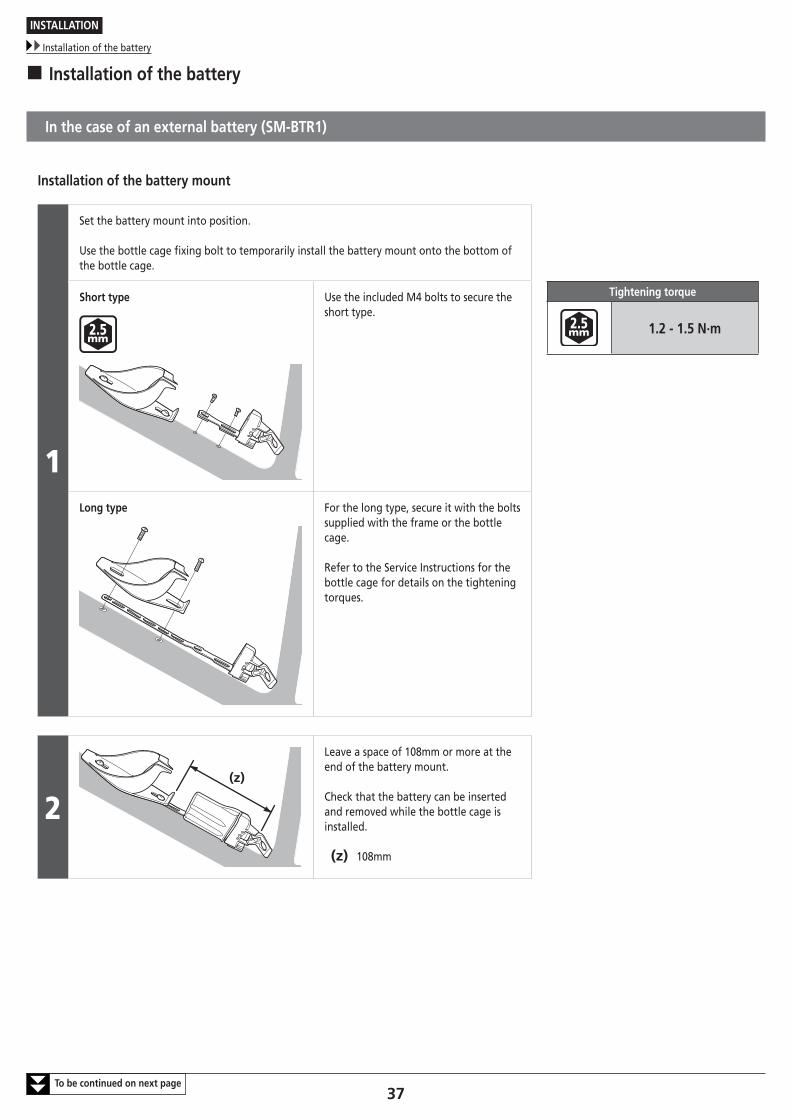
Set the battery mount into position.
Use the bottle cage fixing bolt to temporarily install the battery mount onto the bottom of the bottle cage.
Short type Use the included M4 bolts to secure the short type.
Tightening torque
1.2 - 1.5 N·m
Long type For the long type, secure it with the bolts supplied with the frame or the bottle cage.
Refer to the Service Instructions for the bottle cage for details on the tightening torques.
2(z)
Leave a space of 108mm or more at the end of the battery mount.
Check that the battery can be inserted and removed while the bottle cage is installed.
(z) 108mm
38
INSTALLATION
Installation of the battery
To be continued on next page
3
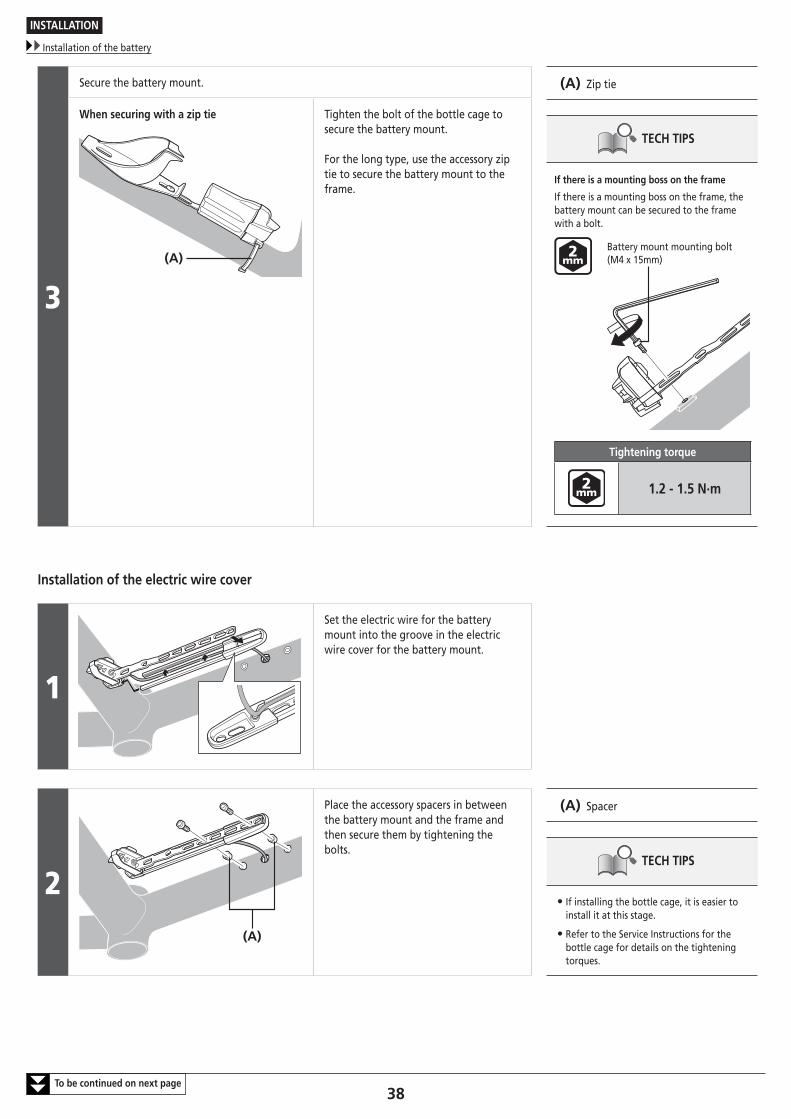
Secure the battery mount. (A) Zip tie
TECH TIPS
If there is a mounting boss on the frame
If there is a mounting boss on the frame, the battery mount can be secured to the frame with a bolt.
Battery mount mounting bolt (M4 x 15mm)
Tightening torque
1.2 - 1.5 N·m
When securing with a zip tie
(A)
Tighten the bolt of the bottle cage to secure the battery mount.
For the long type, use the accessory zip tie to secure the battery mount to the frame.
Installation of the electric wire cover
1
Set the electric wire for the battery mount into the groove in the electric wire cover for the battery mount.
2(A)
Place the accessory spacers in between the battery mount and the frame and then secure them by tightening the bolts.
(A) Spacer
TECH TIPS
• If installing the bottle cage, it is easier to install it at this stage.
• Refer to the Service Instructions for the bottle cage for details on the tightening torques.
39
INSTALLATION
Installation of the battery
3
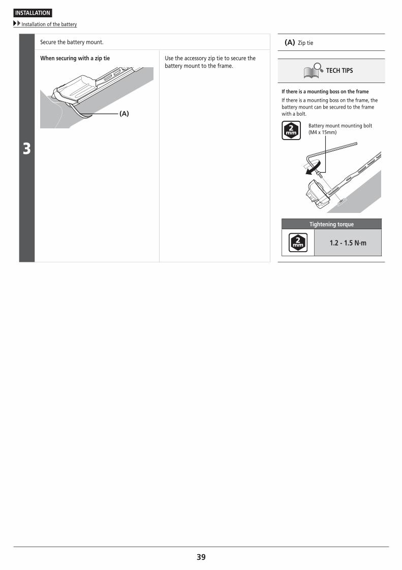
Secure the battery mount. (A) Zip tie
TECH TIPS
If there is a mounting boss on the frame
If there is a mounting boss on the frame, the battery mount can be secured to the frame with a bolt.
Battery mount mounting bolt (M4 x 15mm)
Tightening torque
1.2 - 1.5 N·m
When securing with a zip tie
(A)
Use the accessory zip tie to secure the battery mount to the frame.

40
INSTALLATION
Installation of the battery
Installation of the bottle cage adapter
If the bottle cage which is installed to the seat tube interferes with the battery, move the position of the bottle cage upward.
The installation position for the bottle cage can be moved upward by a minimum of 32mm and a maximum of 50mm from the original installation position.
(y) 15mm
(z) 10mm
(A) Spacer
Tightening torque
3 N·m
TECH TIPS
• If it interferes with the mounting boss for the front derailleur, use the included spacer.
• Refer to the Service Instructions for the bottle cage for details on the tightening torques.
(z)
(z)
(y)
(y)
(A)

41
INSTALLATION
Installation of the battery
In the case of a built-in battery (SM-BTR2/BT-DN110)
Installation of the built-in battery
1(A)
(B)
Insert the seat post collar into the seat post.
(A) Seat post
(B) Seat post collar
TECH TIPS
• Depending on the type of frame, the way the lithium ion battery (built-in type) is installed may differ. For details, contact a manufacturer of completed bicycles.
• Prepare a seat post that is compatible with DI2 (SM-BTR2/BT-DN110).
* If you have any questions, consult with the manufacturer of seat post.
2
(A)
(B)
Insert the lithium ion battery (built-in type) into the seat post collar from the bottom of the seat post.
(A) Seat post collar
(B) Built-in battery (SM-BTR2/BT-DN110)
3(C)
(D)
(A)
(B)
(A)
Mount a wave washer between two washers to the groove of the battery adapter, and fix them in place with a snap ring.
(A) Washer
(B) Wave washer
(C) Snap ring
(D) Battery adapter
TECH TIPS
Use snap ring pliers (with a claw diameter of 2.0mm or less) to mount the snap ring.

42
INSTALLATION
Installation of the battery
In the case of an external battery (SM-BTR2, BT-DN110/SM-BTC1)
Preparing to install
1
(C)
(B)
(A)
Affix the protective sheet to the battery.
Remove the back sheet from the back of the protective sheet and wrap the protective sheet around the battery for one turn with the groove in the protective sheet aligned with the groove in the battery as shown in the illustration.
(A) Battery (SM-BTR2/BT-DN110)
(B) Protective sheet
(C) Groove
NOTE
Wipe off any dirt or oil from the battery before affixing the protective sheet.
2(A)
(B)
Insert the O-ring included with the battery case into the groove from below the battery.
(A) Groove
(B) O-ring

43
INSTALLATION
Installation of the battery
To be continued on next page
Installing the battery case and connecting the electric wires
1
Use the mounting bolts to mount the battery case to the frame at one of the mounting points so that bolts are in the center of the frame installation holes of the battery case as shown in the illustration.
(A) Battery case
(B) Frame installation hole
(C) Washer
(D) Fixing bolt (M5)
Tightening torque
2.5 - 3 N·m
NOTE
When installing the bottle cage, do so using whichever torque is the lowest among the battery case, the frame, or the bottle cage's respective tightening torque upper limits.
(C)
(D)
(B)
(A)
2
(D)(C)(B)(A)
Connect the electric wires.
Connect the electric wires from each component to an empty port in the junction assembly.
Use the Shimano original tool when connecting.
Be sure to connect dummy plugs to any unused ports.
(A) Junction assembly
(B) Dummy plug
(C) Electric wire
(D) Shimano original tool (TL-EW02)
TECH TIPS
The electric wires for battery connection are connected by default. If the electric wires are disconnected, insert the connector into the port with a depression in it, and fix the electric wire to the groove on the side.
Groove
Hollow

44
INSTALLATION
Installation of the battery
To be continued on next page
3
(A)
Install the junction spacer.
Install the junction spacer and junction assembly so that their directions are aligned as shown in the illustration.
After installation, pass the electric wire through the junction spacer and fi x it in place.
(A) Junction spacer
4
(A)
Pass the electric wires for battery connection through the holes on the inside of the battery case, so that the wires come out the top of the battery case.
(A) Electric wire for battery connection
5
(z)
(A) (B)
(C)
Insert the junction assembly and junction spacer from below the battery case.
Insert the tab on the junction spacer in the direction shown in the illustration.
(z) Junction spacer tab
(A) Junction spacer
(B) Junction assembly
(C) Electric wire for battery connection

45
INSTALLATION
Installation of the battery
6
(B)
(A)Pass the electric wires connected to the junction assembly through the hole in cap A.
Mount cap A to the battery case as shown in the illustration.
Fix to the battery case using the supplied fixing bolt.
(A) Cap A
(B) Fixing bolt (M3)
Tightening torque
0.26 - 0.4 N·m
7(B)
(A)
With the connecting terminal side facing up, insert the battery from the upper part of the battery case.
Install so that the connecting terminal opening is oriented as shown in the illustration.
(A) Connection terminal
(B) Connecting terminal opening
8(A)
Connect the electric wire to the battery connecting terminal using the Shimano original tool.
(A) Shimano original tool (TL-EW02)
9(A)
(B)
Install cap B to the battery case, and fix it in place using the supplied fixing bolt.
(A) Cap B
(B) Fixing bolt
Tightening torque
0.26 - 0.4 N·m
NOTE
Make sure that the electric wire is not pinched by the cap.

46
INSTALLATION
Installation of the battery
Removing the battery
(A) (B) (C) (D)
(E) (F)
Remove the fixing bolt and cap B from the battery case.
Disconnect the electric wire from the battery using the Shimano original tool.
Insert a 2.5mm hexagon wrench into the hole in cap A on the opposite side and push out the battery.
(A) Cap B
(B) Electric wire
(C) Battery
(D) Battery case
(E) Fixing bolt
(F) 2.5mm hexagon wrench
Connecting the suspension
When connecting the suspension, use one that is compatible with the system. For details on how to connect it, contact the manufacturer of the suspension.
Checking connections
Connect the electric wires to all of the components, install the battery, and then check the operation.
(A)
Operate the shifting switches and check that the front and rear derailleurs both operate.
(A) Shifting switch
TECH TIPS
If the front or rear derailleur does not operate properly, refer to the section "CONNECTION AND COMMUNICATION WITH DEVICES".

47
INSTALLATION
Installation of the chain
� Installation of the chain
Chain length
[a]
[a’]
+
(B)(A) (C)
The length of [a] will vary depending on the movement of the rear suspension.
Consequently, an excessive load may be placed on the drive system if the chain length is too short.
The rear suspension operates and stops when dimension [a] is at its greatest extension.
Mount the chain on to the largest sprocket and the largest chainring.
Next, add 2 links to set the length of the chain.
(A) Largest sprocket
(B) Chain
(C) Largest chainring
(A)(A)
(A) Chain derailment prevention plate
NOTE
• If there is a lot of movement in the rear suspension, the slack in the chain may not be taken up properly when the chain is on the smallest chainring and smallest sprocket. Add 2 links (with the chain on the largest sprocket and the largest chainring).
• The rear derailleur plate assembly is equipped with a pin or plate that prevents the chain from derailing. When passing the chain through the rear derailleur, pass it through the rear derailleur body from the side of the chain derailment prevention plate as shown in the illustration. If the chain is not passed through the correct position, damage may be caused to the chain or rear derailleur.
TECH TIPS
The same chain length checking method applies to the double front gear and the single front gear.

HOW TO OPERATE

49
HOW TO OPERATE
Basic operations of the shifting switch
HOW TO OPERATE
� Basic operations of the shifting switch
[Y] [X]
[Y][X]
[Y][X]
[X][Y]
Factory default setting of the shifting switch: The shifting switch is set at default to shift the gear in the directions shown in the illustration.
NOTE
Check the firmware version of the system before use. Check the version compatibility of the firmware according to the section "CONNECTION AND COMMUNICATION WITH DEVICES". If the firmware is old, update it to the latest version.
TECH TIPS
You can configure the settings in E-TUBE PROJECT. For details, refer to "CONNECTION AND COMMUNICATION WITH DEVICES" – "Settings customizable in E-TUBE PROJECT".

50
HOW TO OPERATE
Gear position control
� Gear position control
This gear-shifting system is programmed to prevent shifting into gears that would lower the chain tension.Therefore, if you try to shift into such gears, shifting may function differently from the basic operations.The illustration below shows the gear positions that would lower the chain tension and the shifting operations performed when you shift into those gears.
Points to remember when shifting the front derailleur
When you shift into the smallest chainring, shifting is controlled as follows.
GS
[1]
SGS
[2]
When the chain is in the ranges [1] or [2] in the illustrationOperating the shifting switch does not shift the front derailleur.
Instead, the rear derailleur is shifted down through two gears.
When the chain is outside the ranges [1] or [2] in the illustrationOperating the shifting switch shifts the front derailleur to the smallest chainring.
[1] From the smallest to the third sprocket.
[2] Smallest sprocket
NOTE
• If you use combinations of front and rear derailleurs besides those recommended, the shifting-restricted range may become larger.
Points to remember when shifting the rear derailleur
When the chain position is in the smallest front chainring, gear shifting is controlled as follows.
[1]
GS SGS
[2]
When shifting the rear in the direction of the smallest sprocketOperating the shifting switch will not shift the chain into ranges [1] or [2] in the illustration.
[1] From the smallest to the third sprocket.
[2] Smallest sprocket

51
HOW TO OPERATE
Displaying and operating the system information display
� Displaying and operating the system information display
Names of parts
(D)
(A) (B)
(C)
(A) Mode switch
(B) Terminal section
(C) Charging port
(D) Clamp band
Basic screen display
(E)
(A) (B) (C) (D) (A) Battery level
(B) Front derailleur Gear position
(C) Rear derailleur Gear position/Adjustment level/ RD Protection Reset mode
(D) Suspension setting
(E) Operation mode

52
HOW TO OPERATE
Displaying and operating the system information display
Battery level
(A) (A) Battery level
Display Battery level
81% – 100%
61% – 80%
41% – 60%
26% – 40%
1% – 25%*1*2*3
0%*3
TECH TIPS
*1 When the battery level is low, the operation of the suspension will be limited to the lock release. The operation of the rear suspension is restricted first, then that of the front suspension.
*2 When the battery level drops below 5%, the operation of the front derailleur is restricted.
*3 When the battery level decreases further, both the suspensions and derailleurs cease operating, with the derailleurs fixed at the last shifted position. The battery indicator blinks for 2 seconds at the time of input operation. It is recommended to charge the battery as soon as possible.

53
HOW TO OPERATE
Displaying and operating the system information display
Front derailleur: Gear position
(B) (B) Front derailleur: Gear position
Display Gear position
Largest chainring
Middle chainring
Smallest chainring
TECH TIPS
The gear position of the front derailleur is displayed.
* In the case of double specification, only the largest chainring and smallest chainring are displayed.
Rear derailleur: Gear position/Adjustment level
(C) (C) Rear derailleur: Gear position/Adjustment level
Setting mode Details
Shift mode The gear position of the rear derailleur is displayed.
Adjustment mode When adjusting the front derailleur and rear derailleur, the adjustment level
is displayed.
TECH TIPS
The display information varies depending on the mode setting.

54
HOW TO OPERATE
Displaying and operating the system information display
RD Protection Reset mode
(C) (C) RD Protection Reset mode
Display Details
RD Protection Reset will operate.
TECH TIPS
The display information varies depending on the mode setting.
Suspension setting
(D) (D) Suspension setting
Display Details
If the suspension settings are already configured, one of the settings can be
selected from the screen indications.* 1*2
If the suspension settings are not configured, the suspensions are not
connected, or the battery level is running low, the display will be blank.
TECH TIPS
Three types of front and rear suspension combinations can be configured.
*1 Suspension settings are configured in E-TUBE PROJECT. For details, consult a dealer or an agency.
*2 Depending on the type of suspension, settings may be factory configured at the time of shipment. Check the indications displayed on the information display screen, and if the arrows are displayed, be sure to check the setting details.

55
HOW TO OPERATE
Displaying and operating the system information display
Operation mode
(E)
(E) Operation mode
Display Details
Adjustment setting (front derailleur/rear derailleur)The front derailleur or rear derailleur can be adjusted in this mode. For the setting procedure, contact a dealer or an agency.
Manual shiftGears are shifted manually in this mode.
Shift mode 1
The shift mode set in E-TUBE PROJECT can be used. The initial setting for
MTB is Synchronized shift 1.
This setting mode is designed for riders with strong legs.
Shift mode 2
The shift mode set in E-TUBE PROJECT can be used. The initial setting for
MTB is Synchronized shift 2.
This setting mode is designed for courses with considerable terrain variation.

56
HOW TO OPERATE
Displaying and operating the system information display
How to operate
(z)
(x) (y)Single click (2 seconds)
Single click (0.5 seconds)
Double click
Pressing and holding down (5 seconds or more)
(x) Shift mode
(y) Adjustment mode
(z) RD Protection Reset is activated.
Switching operating modesWhen using a system information display, combine it with one of the following units. External type: BM-DN100, Built-in type: BT-DN110
You can switch between operating modes with a single click (2 seconds).
Switching selections in each mode
Double click to switch selections within the mode.

57
HOW TO OPERATE
Error message
RD Protection Reset
Holding the mode button down for at least 5 seconds when RD Protection is in operation will reset the system connection and restore normal operation.
TECH TIPS
RD Protection is a function that cuts the transmission of power between the motor and the link in cases where the rear derailleur is pressed in by a strong impact such as from when falling from the bicycle. The rear derailleur cannot function when RD Protection is in operation.If this happens, pressing the mode button on the system information display or the button on junction A for 5 seconds or more will restore the connection between the motor and the link and the rear derailleur will start operating normally. The connection can also be restored manually. For details, contact the distributor.
� Error message
About the beep
Beep sounds Situation
One short beep
Indicates that the gear shifting limit has been reached. (When the chain is on
the highest gear for both front and rear or lowest gear for both front and
rear)
Two short beeps Indicates that the front chainrings are being shifted in the synchronized shift
mode. These beeps sound the next time the front chainrings are shifted.
One long beep
Indicates that the front derailleur cannot be shifted when the battery is
running low. Blinking continues for 2 seconds after the sound has stopped.
(Only one beep sounds when the gears are shifted)
Indicates that there is an error with the suspension.
All suspension mode arrows blink and continue to blink for 2 seconds after
the sound has stopped.
TECH TIPS
Beeps are set to sound in certain situations during gear operation.

58
HOW TO OPERATE
About wireless functions
To be continued on next page
� About wireless functions
Functions
ANT connection
ANT connection facilitates the transmission of the following three types of information to compatible cycle computers or receivers.
(1) Gear position (front, rear)
(2) DI2 battery level information
(3) Adjustment mode information
For information on which of the above types of information are displayed, refer to the manual for your cycle computer or receiver.
TECH TIPS
The latest functions can be checked by updating the software via E-TUBE PROJECT. For details, consult the place of purchase.
Bluetooth® LE connectionE-TUBE PROJECT for smartphones/tablets may be used if a Bluetooth LE connection is established with a smartphone/tablet.
How to make connections
ANT connectionTo make a connection, the cycle computer needs to be in connection mode. For information on how to put the cycle computer into connection mode, refer to the manual for the cycle computer.
1 Put the cycle computer into connection mode.
2
When using an external batteryCheck that the electric wires are connected to the system information display, and then remove and remount the external battery.
When using a built-in batteryCheck that the electric wires are connected to the system information display, and then remove the electric wires from the system information display and reconnect them.
TECH TIPS
Connection transmission begins about 30 seconds after the battery is remounted or the electric wires are reconnected to the system information display.

59
HOW TO OPERATE
About wireless functions
3
This completes the connection process. TECH TIPS
• Check on the cycle computer to see if connection was successful.
• If a connection cannot be made in the way described above, refer to the manual for your cycle computer.
• For information on how to show gear position or the DI2 battery level, refer to the manual for the cycle computer.
Bluetooth® LE connectionBefore setting up a connection, turn on Bluetooth LE on the smartphone/tablet.
1 Open E-TUBE PROJECT and set it to listen for Bluetooth LE signals.
2
Setting up via information displayPress the mode switch until "C" appears on the display.
Setting up via junction APress the button on junction (A) until the green LED and red LED begin to blink alternately.
3The unit on the bicycle will begin signal transmission. The unit name displays in E-TUBE PROJECT.(Release the mode switch or button as soon as the unit on the bicycle begins signal transmission. If the mode switch or button is held down for any longer, a different mode will be activated.)
4
Select the unit name displayed on screen. TECH TIPS
To disconnect, cancel the Bluetooth LE connection from the smartphone/tablet. (The cycle computer will exit connection mode and return to regular operation mode.)

ADJUSTMENT

61
ADJUSTMENT
Adjustment of the rear derailleur
To be continued on next page
ADJUSTMENT
� Adjustment of the rear derailleur
1 Install the battery.
2
(A) (B) (D)
(C)
(z)
Adjust the end adjust bolt.
Mount the chain on the smallest chainring and the largest sprocket, and turn the crank arm.
Adjust the end adjust bolt so that the guide pulley does not interfere with the sprocket, but do not let the guide pulley come so close to the chain that they come into contact with each other.
(z) 2mm hexagon wrench
(A) Largest sprocket
(B) Smallest sprocket
(C) Guide pulley
(D) End adjust bolt
Checking the distance between the largest sprocket and the guide pulley
(z)
(A)
(B)
Set the rear derailleur on the largest sprocket, and with the wheel stopped, make sure that the clearance between the tip of the guide pulley and the tip of the largest sprocket is within the range (z).
(z) 5 - 6mm (When largest sprocket is a 42T sprocket or smaller) 8 - 9mm (When largest sprocket is a 46T sprocket or smaller)
(A) Largest sprocket
(B) Guide pulley
NOTE
Check the distance between the largest sprocket and the guide pulley with the rear suspension at its greatest extension.
3
Shift the rear derailleur to the 5th sprocket position.

62
ADJUSTMENT
Adjustment of the rear derailleur
To be continued on next page
4
Switch to adjustment mode.
In the case of system information display
(C) (B)
(A)
Single click the button (2 seconds) to switch to adjustment mode.
The adjustment mode indicator "R" flashes.
(A) Button
(B) Adjustment level
(C) Adjustment mode
In the case of Junction A
(A)
(B)
Press the junction A button until the red LED lights up.
(A) Button
(B) Red LED
NOTE
When operating junction A, note that if you keep pressing the button after the red LED has illuminated, RD Protection Reset will begin.
TECH TIPS
For details on RD Protection, refer to "About the RD Protection Function" in the user’s manual for the rear derailleur (DI2).

63
ADJUSTMENT
Adjustment of the rear derailleur
To be continued on next page
5
[X] [Y]
[Y] [X]
If shifting switch [Y] is pressed once while the initial setting condition is active, the guide pulley will move one step toward the inside.
If shifting switch [X] is pressed once, the guide pulley will move one step toward the outside.
TECH TIPS
The guide pulley can move 16 steps inward and 16 steps outward from the initial position, for a total of 33 positions.
6
[Y]
While turning the front chainwheel, operate shifting switch [Y] to move the guide pulley toward the inside until the chain touches the 4th sprocket and makes a slight noise.

64
ADJUSTMENT
Adjustment of the rear derailleur
To be continued on next page
7
[X]
Next, operate shifting switch [X] 5 times to move the guide pulley toward the outside by 5 steps to the target position.
8
Exit adjustment mode.
In the case of system information display Single click the button (0.5 seconds) to switch from adjustment mode to shift mode.
In the case of Junction A Press the button at junction A until the red LED turns off in order to switch from rear derailleur adjustment mode to gear shifting mode.

65
ADJUSTMENT
Adjustment of the rear derailleur
9Shift to each gear and check that no noise or chain jamming is generated at any gear position.
If adjustment is needed, switch back to adjustment mode and readjust the rear derailleur.
10
(A)(z)
Adjust the low-side stopper adjustment bolt with a 2mm hexagon wrench.
Shift the rear derailleur to the largest sprocket, and then tighten the low-side stopper adjustment bolt until it just touches the outer link.
If it is tightened too much, the motor will detect a problem and gear shifting will not operate correctly.
(z) 2mm hexagon wrench
(A) Low-side stopper adjustment bolt
TECH TIPS
Possible occurrences if the adjustment bolt is overtightened
• Gears do not shift to the top/low gear. (Even if you shift gears to the top or low gear, the gear may shift back by one gear after about 5 seconds.)
• Noise does not stop.
• The battery level drops quickly. (Load is being placed on the motor)
• The motor may be damaged. (irreparable)
11
(A)(z)
Adjust the top-side stopper bolt with a 2mm hexagon wrench.
Shift to the smallest sprocket, and then tighten the top-side stopper bolt until it touches the inner link at the position where the rear derailleur stops.
(z) 2mm hexagon wrench
(A) Top-side stopper bolt

66
ADJUSTMENT
Adjustment of the front derailleur
To be continued on next page
� Adjustment of the front derailleur
Adjust the front derailleur using the following procedure.
Top side position adjustment Use the adjustment bolt of the front derailleur for
adjustment.
Low-side position adjustmentSwitch the system information display to adjustment mode
and use the shifting switch for adjustment.
TECH TIPS
The shifting switch configuration is divided into two types: right and left shifting switches or a one-side shifting switch. The adjustment of the front derailleur differs depending on the type used. Refer to "When using two shifting switches for adjustment" or "When using one shifting switch for adjustment" depending on the number of shifting switches your bicycle has.
When using two shifting switches for adjustment
Top side position adjustment
1
(A)
(B)
(B) (A)
Set the chain onto the largest chainring and the largest sprocket.
(A) Largest chainring
(B) Largest sprocket
TECH TIPS
If the rear derailleur cannot be set to the largest sprocket in synchronized mode, switch to manual mode before setting the rear derailleur to the largest sprocket.
2(A)(z)
Loosen the stroke mounting bolt with a 2mm hexagon wrench.
(z) 2mm hexagon wrench
(A) Stroke mounting bolt

67
ADJUSTMENT
Adjustment of the front derailleur
3
(z)
(A)(z)
Turn the top adjustment bolt with a 2mm hexagon wrench to adjust the clearance.
Adjust the chain guide while pushing it towards B.
Adjust so that there is a clearance of 0 – 0.5mm between the chain and the chain guide inner plate.
(y) 0 - 0.5mm
(z) 2mm hexagon wrench
(A) Top adjustment bolt
4(A)
After adjustment, securely tighten the stroke mounting bolt while pushing the chain guide towards the frame.
(A) Stroke mounting bolt
Tightening torque
0.5 N·m

68
ADJUSTMENT
Adjustment of the front derailleur
To be continued on next page
Low-side position adjustment
1
Set the chain on the smallest chainring at the front and the largest sprocket at the rear.
2
Switch to adjustment mode.
In the case of system information display
(A) (B)
Single click the button (2 seconds) to switch to adjustment mode. The adjustment mode indication "R" and the adjustment level indicator flash.
(A) Adjustment mode
(B) Adjustment level
In the case of Junction A Press the junction A button until the red LED lights up.

69
ADJUSTMENT
Adjustment of the front derailleur
3
(z)
[Y]
[Y][X]
[X]
Press the lever of the front-side shifting switch to adjust the clearance.
Adjust so that there is a clearance of 0 – 0.5mm between the chain and the chain guide inner plate.
(z) 0 - 0.5mm
4
After adjustment, switch to adjustment mode.
In the case of system information display Single click the button (0.5 seconds) to switch from adjustment mode to shift mode.
In the case of Junction A Press the button at junction A until the red LED turns off in order to switch from rear derailleur adjustment mode to gear shifting mode.

70
ADJUSTMENT
Adjustment of the front derailleur
To be continued on next page
When using one shifting switch for adjustment
Top side position adjustment
1
(A)
(B)
(B) (A)
Set the chain onto the largest chainring and the largest sprocket.
(A) Largest chainring
(B) Largest sprocket
TECH TIPS
If the rear derailleur cannot be set to the largest sprocket in synchronized mode, switch to manual mode before setting the rear derailleur to the largest sprocket.
2(A)(z)
Loosen the stroke mounting bolt with a 2mm hexagon wrench.
(z) 2mm hexagon wrench
(A) Stroke mounting bolt
3
(y)
(A)(z)
Turn the top adjustment bolt with a 2mm hexagon wrench to adjust the clearance.
Adjust the chain guide while pushing it towards B.
Adjust so that there is a clearance of 0 – 0.5mm between the chain and the chain guide inner plate.
(y) 0 - 0.5mm
(z) 2mm hexagon wrench
(A) Top adjustment bolt

71
ADJUSTMENT
Adjustment of the front derailleur
To be continued on next page
4(A)
After adjustment, securely tighten the stroke mounting bolt while pushing the chain guide towards the frame.
(A) Stroke mounting bolt
Tightening torque
0.5 N·m
Low-side position adjustment
1
Set the chain on the smallest chainring at the front and the largest sprocket at the rear.
2
(A) (B)
Single click the button (2 seconds) to switch to adjustment mode.
The adjustment mode indicator "R" flashes.
(A) Adjustment mode
(B) Adjustment level

72
ADJUSTMENT
Adjustment of the front derailleur
3
(A)
Switch the adjustment mode.
Every time the button is double-clicked, the blinking indicator switches between "F" and "R".
Select "F" for front derailleur adjustment.
(A) Front derailleur adjustment
4
(z)
[Y]
[Y][X]
[X]
Press the lever of the shift switch to adjust the clearance.
Adjust so that there is a clearance of 0 – 0.5mm between the chain and the chain guide inner plate.
(z) 0 - 0.5mm
5
After adjustment, single click the button (0.5 seconds) to switch from adjustment mode to shift mode.

73
ADJUSTMENT
Adjusting rear derailleur friction
To be continued on next page
Troubleshooting chart
After adjusting the front derailleur, check the shifting by operating the shifting lever.(This also applies if shifting becomes difficult during use.) Use the table as a reference when adjusting the bolts. Turn the screw by 1/8 of a turn for each adjustment of the top side position and by 1 click for each adjustment of the low side position.
NOTE
After adjusting the top adjustment bolt, recheck the low side position.
If the chain falls to the crank side. Turn the top adjustment bolt counterclockwise.
If shifting is difficult from the smallest chainring to
the largest chainring.
Turn the top adjustment bolt clockwise.
If shifting is difficult from the largest chainring to the
smallest chainring.
Perform readjustment according to "Low-side position adjustment" in "Adjustment of the
front derailleur". Adjust the chain guide inward (X direction).
If the chain falls to the bottom bracket side. Perform readjustment according to "Low-side position adjustment" in "Adjustment of the
front derailleur". Adjust the chain guide outward (Y direction).
� Adjusting rear derailleur friction
The friction capacity can be adjusted as desired. Furthermore, you can also adjust after a change of the friction occurs during use.
Friction adjustment
1 Move the lever switch to the ON position.
2(A)
Remove the plate unit cap by hand as shown in the illustration.
(A) Plate unit cap

74
ADJUSTMENT
Adjusting rear derailleur friction
3(A)
(B)
Turn the friction adjustment bolt with a 2mm hexagon wrench to adjust the friction.
(A) Friction adjustment bolt
(B) 2mm hexagon wrench
4(A)
Insert a hexalobular wrench into the left plate and check the friction torque.
(A) Left plate
Friction torque
3.5 - 5.4 N·m
5
(A) Install the plate unit cap so that it is in the position shown in the illustration.
(A) Plate unit cap

CHARGING THE BATTERY

76
CHARGING THE BATTERY
Names of parts
CHARGING THE BATTERY
Use the specified combination of lithium ion batteries, chargers, and linkage devices.Any other combinations may cause rupture or fire.Fully understand the precautions for use provided at the beginning of the dealer's manual before using the products.
� Names of parts
External type (SM-BCR1/SM-BTR1)
Battery charger (SM-BCR1)
(A)
(B)
(F)
(D)
(E)
(C)
(A) Electrical contacts: If these are modified or damaged, problems with operation will occur. Be very careful when handling them.
(B) ERROR indicator: This flashes when there is an error.
(C) CHARGE indicator: This illuminates while charging is in progress.
(D) Power cord connector
(E) Power cord: Insert into the connector. Insert all the way.
(F) Charger cord (Sold separately)
TECH TIPS
This is a special charger for charging Shimano lithium ion batteries (SM-BTR1).

77
CHARGING THE BATTERY
Names of parts
Special battery (SM-BTR1)
(A)
(A) Electrical contacts: If these are modified or damaged, problems with operation will occur. Be very careful when handling them.
TECH TIPS
This is a lithium ion battery.Use the special charger (SM-BCR1) to charge it.
Built-in type (SM-BCR2/SM-BTR2, BT-DN110)
USB cable
(A) (B)
(A) Micro USB plug: Connect to the battery charger.
(B) USB plug: Connect to a PC USB port or an AC adapter with a USB port.
Battery charger (SM-BCR2)
(A) (D)(B) (C)
(A) Micro USB connector
(B) CHARGE indicator
(C) ERROR indicator
(D) Plug for product connection: Connect to junction A or the charging connector of the system information display.
TECH TIPS
• This is a special charger for charging Shimano lithium ion batteries (SM-BTR2/BT-DN110).
• If water collects in the product connector, connect the plug only after wiping it off.

78
CHARGING THE BATTERY
Charging the battery
Battery (SM-BTR2/BT-DN110)
TECH TIPS
This is a lithium ion battery.Use the special charger (SM-BCR2) to charge it.
� Charging the battery
External type (SM-BCR1/SM-BTR1)
1 Insert the power plug of the battery charger into an electrical outlet.
2
Insert the battery (SM-BTR1) into the battery charger (SM-BCR1) as far as it will go.
TECH TIPS
Charging takes up to approximately 1.5 hours. (Note that the actual time will vary depending on the remaining battery charge.)
3
(A)
When the CHARGE indicator (orange) switches off, charging is complete.
(A) CHARGE indicator
TECH TIPS
If the ERROR indicator flashes, it means that there may be a problem with the battery.Refer to "When charging is not possible" for more information.
4 Disconnect the power plug of the battery charger from the electrical outlet and store the battery charger in a suitable place as specified in the safety precautions.

79
CHARGING THE BATTERY
Charging the battery
Built-in type (SM-BCR2/SM-BTR2, BT-DN110)
1Connect the battery to junction A or the system information display. TECH TIPS
The battery can be charged by using an AC adapter with a USB port or connecting the charger to the USB connector of a PC.
2
Connect the charging cable of the battery charger to junction A or the charging port of the system information display.
(z) To an AC adapter with a USB port or PC
(A) Charging port
TECH TIPS
• The position of the charging port differs depending on the product.
• The charging time of an AC adapter with a USB port is about 1.5 hours, and that of computer USB port type about 3 hours. (Note that the actual time will vary depending on the amount of charge remaining in the battery. Depending on the specifications of the AC adapter, recharging via the AC adapter may require as much time (about 3 hours) as recharging via PC.)
(A)
(z)
3When the CHARGE indicator (orange) switches off, charging is complete. TECH TIPS
If ERROR indicator or CHARGE indicator blinks, refer to "When charging is not possible".
4 Disconnect the charging cable or USB cable, and keep it at the location specified in the precautions.

80
CHARGING THE BATTERY
When charging is not possible
� When charging is not possible
External type (SM-BCR1/SM-BTR1)
(z)
Remove the battery from the battery charger, disconnect the power plug of the battery charger from the electrical outlet, and then repeat the charging operation.
If charging is still not possible after the above steps have been carried out, the ambient temperature may be too low or too high, or there may be a problem with the battery.
(z) If charging is not possible, the ERROR indicator on the battery charger will flash.
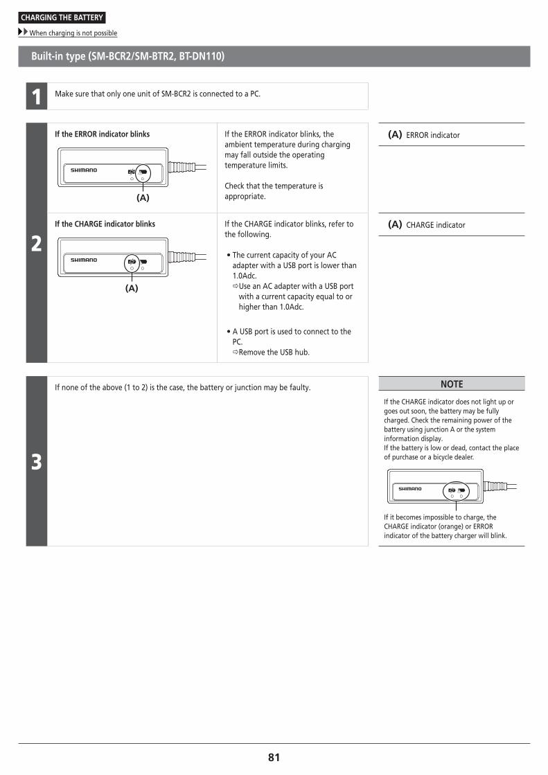
81
CHARGING THE BATTERY
When charging is not possible
Built-in type (SM-BCR2/SM-BTR2, BT-DN110)
1 Make sure that only one unit of SM-BCR2 is connected to a PC.
2
If the ERROR indicator blinks
(A)
If the ERROR indicator blinks, the ambient temperature during charging may fall outside the operating temperature limits.
Check that the temperature is appropriate.
(A) ERROR indicator
If the CHARGE indicator blinks
(A)
If the CHARGE indicator blinks, refer to the following.
• The current capacity of your AC adapter with a USB port is lower than 1.0Adc. Use an AC adapter with a USB port
with a current capacity equal to or higher than 1.0Adc.
• A USB port is used to connect to the PC. Remove the USB hub.
(A) CHARGE indicator
3
If none of the above (1 to 2) is the case, the battery or junction may be faulty. NOTE
If the CHARGE indicator does not light up or goes out soon, the battery may be fully charged. Check the remaining power of the battery using junction A or the system information display.If the battery is low or dead, contact the place of purchase or a bicycle dealer.
If it becomes impossible to charge, the CHARGE indicator (orange) or ERROR indicator of the battery charger will blink.

CONNECTION AND COMMUNICATION WITH DEVICES

83
CONNECTION AND COMMUNICATION WITH DEVICES
Settings customizable in E-TUBE PROJECT
CONNECTION AND COMMUNICATION WITH DEVICES
Connecting the bicycle (system or components) to a device enables such operations as updating system firmware and customization.
You need E-TUBE PROJECT to configure the system and update firmware.
Download E-TUBE PROJECT from our support website (http://e-tubeproject.shimano.com).
For information on how to install E-TUBE PROJECT, check the support website.
TECH TIPS
You need SM-PCE1 and SM-JC40/JC41 to connect the system to a PC. They are not required if there is an available port.Firmware is subject to change without notice.
System requirements
PC linkage device E-TUBE PROJECT Firmware
SM-BMR2/
SM-BTR2 SM-PCE1/
SM-BCR2Version 3.0.0 or later
Version 3.0.0 or later
BT-DN110/
BM-DN100
Version 4.0.0 or later
* Pre-installed firmware is version 4.0.0.
NOTE
If your versions of E-TUBE PROJECT software and firmware for each component are not up to date there could be problems operating the bicycle. Check the versions and update them to the latest ones.
� Settings customizable in E-TUBE PROJECT
Display settings
Beep setting You can switch the beep between ON and OFF.
Display time Sets the time until the display turns off when the display monitor is left
unattended.
Switch setting Changes the function settings of the shifting switch and suspension switch.
Synchronized shift map setting Modify the synchronized shift map settings.
Suspension type setting Set the suspension type.
Multi-shift mode setting
Multi-shift mode ON/OFF Select whether or not to use multi-shift.
Gear-shifting interval Sets the gear-shifting interval for multi-shift.
Gear number limit Sets the limit on the number of gears shifted when the shifting switch is held
down.

84
CONNECTION AND COMMUNICATION WITH DEVICES
Settings customizable in E-TUBE PROJECT
Synchronized shift map
Synchronized shift is a function that automatically shifts gears on the front derailleur in synchronization with rear derailleur gear shifting.The numbers of switch gears for synchronized shift are configured by default as shown in the charts.
Triple specification
• Synchronized shift 1 • Synchronized shift 2
(A) (B) (C)CS1234567891011
(A) (B) (C)CS1234567891011
(A) Smallest chainring
(B) Middle chainring
(C) Largest chainring
Double specification
• Synchronized shift 1 • Synchronized shift 2
(A) (B)CS1234567891011
(A) (B)CS1234567891011
(A) Smallest chainring
(B) Largest chainring

85
CONNECTION AND COMMUNICATION WITH DEVICES
Connecting to a PC
� Connecting to a PC
If there is an empty port in the system information display
Remove the dummy plug from the system information display, and connect SM-PCE1. (A) SM-PCE1
(B) Dummy plug
(B)
(A)

86
CONNECTION AND COMMUNICATION WITH DEVICES
Connecting to a PC
To be continued on next page
If there are no empty ports in the system information display
When the electric wire can be disconnected from the shifting switch
1
Disconnect the electric wire between the system information display and shifting switch. (A) Shifting switch
(B) Electric wire
(C) System information display
(A)(B)
(C)

87
CONNECTION AND COMMUNICATION WITH DEVICES
Connecting to a PC
2
Connect an unoccupied port of the system information display or shifting switch to an unoccupied port of SM-PCE1 as shown in the illustration.
Use the two PC link cables provided with SM-PCE1 for connection.
(A) PC link cable
(B) SM-PCE1
(A)
(B)
When the electric wire cannot be disconnected from the shifting switch
SM-JC41 and an electric wire (EW-SD50) are required. (A) Electric wire
(B) SM-JC41
(C) PC link cable
(D) SM-PCE1
(A)(B)
(C)
(D)

MAINTENANCE

89
MAINTENANCE
Replacing parts – shifting switch
MAINTENANCE
� Replacing parts – shifting switch
Replacing the lever
Lever [X] and lever [Y] can be replaced.
[X]
[Y](A)
Remove the lever fixing bolt.
Slide the lever, remove it from the shifting switch, and replace it.
(A) Lever fixing bolt
Tightening torque
0.5 - 0.7 N·m
� Replacing parts – rear derailleur
Replacement of the plate and the plate tension spring
Exploded view

90
MAINTENANCE
Replacing parts – rear derailleur
To be continued on next page
Removal
1
(y)(z)
(A)
Make sure that the lever switch is in the OFF position.
If the lever switch is in the ON position, be sure to move it to the OFF position.
(y) ON
(z) OFF
(A) Friction unit
NOTE
If operating the lever switch while the plate unit cover is removed, press the friction unit with your finger so that it does not fly out.
2(A)
Set the rear derailleur to the lowest gear.
Remove the plate stopper pin with a screwdriver.
(A) Plate stopper pin
Tightening torque
1 N·m
3
(A)Turn the plate to loosen the plate tension spring as shown in the illustration.
(A) Plate
4(A)(z)
Remove the plate unit cover bolts.
(z) 2mm hexagon wrench
(A) Plate unit cover bolts
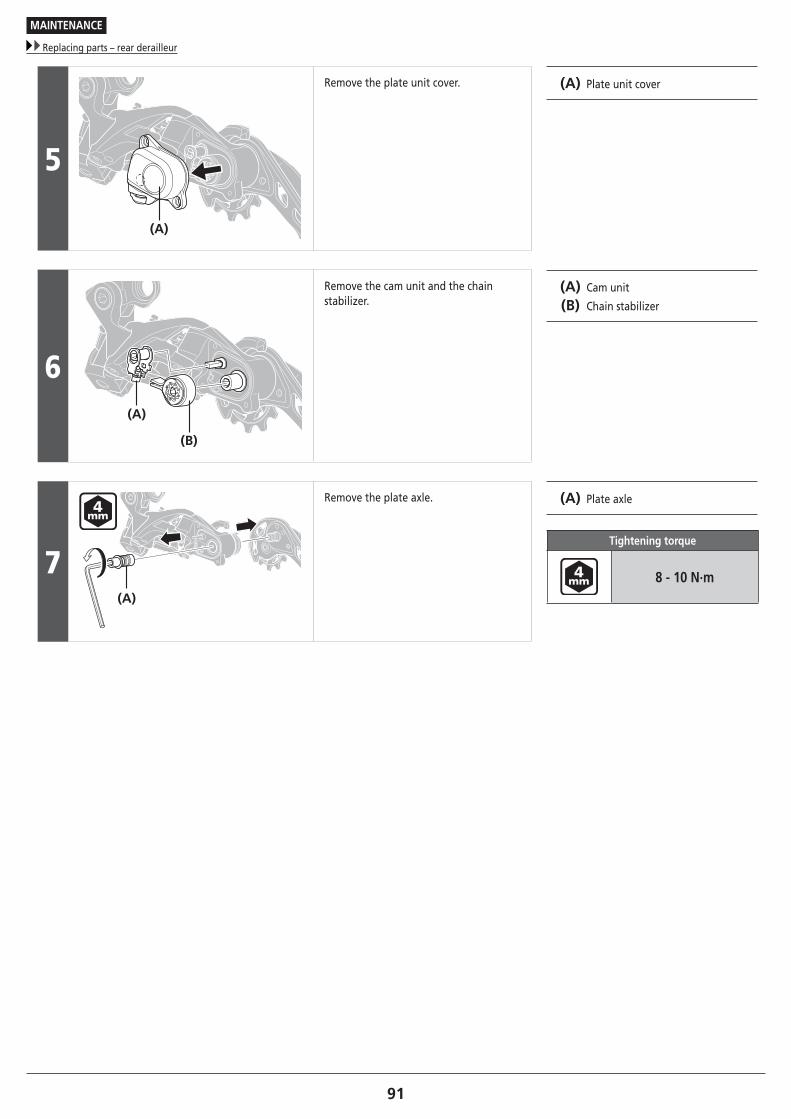
91
MAINTENANCE
Replacing parts – rear derailleur
5
(A)
Remove the plate unit cover. (A) Plate unit cover
6(A)
(B)
Remove the cam unit and the chain stabilizer.
(A) Cam unit
(B) Chain stabilizer
7(A)
Remove the plate axle. (A) Plate axle
Tightening torque
8 - 10 N·m

92
MAINTENANCE
Replacing parts – rear derailleur
To be continued on next page
Installation
1
(A)
(y)(z)
Apply grease to the plate axle.
(y) Grease application area Grease number: Premium grease (Y04110000)
(z) Chain stabilizer side (Do not apply grease)
(A) Plate axle
NOTE
Do not apply grease to the chain stabilizer side of the plate axle.If grease is applied, grease will get on the inner surface of the roller clutch and friction will be lost.
2
(A)
(C)
(B)
Insert the plate axle and insert the tip of the plate tension spring into the groove of the plate.
(A) Plate tension spring
(B) Plate
(C) 4mm hexagon wrench
NOTE
When installing the plate stopper pin, first shift RD to a low position, and then install it.
3
(A)
(B)
(y) (z)
Set the cam unit as shown in the illustration.
(y) Protrusion
(z) Uneven
(A) Cam unit
(B) Chain stabilizer
NOTE
Make sure the cam unit is not set as shown in the following illustration.
Uneven
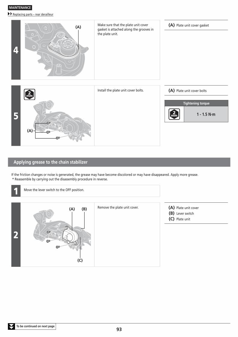
93
MAINTENANCE
Replacing parts – rear derailleur
To be continued on next page
4
(A) Make sure that the plate unit cover gasket is attached along the grooves in the plate unit.
(A) Plate unit cover gasket
5(A)
Install the plate unit cover bolts. (A) Plate unit cover bolts
Tightening torque
1 - 1.5 N·m
Applying grease to the chain stabilizer
If the friction changes or noise is generated, the grease may have become discolored or may have disappeared. Apply more grease.* Reassemble by carrying out the disassembly procedure in reverse.
1 Move the lever switch to the OFF position.
2
(A) (B)
(C)
Remove the plate unit cover. (A) Plate unit cover
(B) Lever switch
(C) Plate unit

94
MAINTENANCE
Replacing parts – rear derailleur
3(A)
Remove the chain stabilizer. (A) Chain stabilizer
4(z)
Apply grease to the clutch.
(z) Grease number: Y04120800
NOTE
Be careful not to get grease on the inner surface of the roller clutch. If grease gets inside the clutch, it will cause the clutch to malfunction.
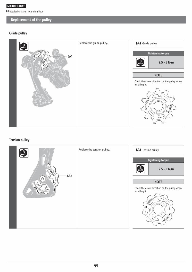
95
MAINTENANCE
Replacing parts – rear derailleur
Replacement of the pulley
Guide pulley
(A)
Replace the guide pulley. (A) Guide pulley
Tightening torque
2.5 - 5 N·m
NOTE
Check the arrow direction on the pulley when installing it.
Tension pulley
(A)
Replace the tension pulley. (A) Tension pulley
Tightening torque
2.5 - 5 N·m
NOTE
Check the arrow direction on the pulley when installing it.

96
MAINTENANCE
Replacing rubber pad B
� Replacing rubber pad B
Removal
1
(A) Turn over rubber pad B from the backside of the chain guide and remove it.
(A) Rubber pad B
2
Remove rubber pad B from the chain guide.
Installation
1
(A) Align the rubber pad B mounting hole of the chain guide with the protrusion of rubber pad B.
(A) Rubber pad B mounting hole
2
Push in the protrusion from the reverse side of rubber pad B.
3
Make sure that the protrusion of rubber pad B is securely fitted on the chain guide.

97
MAINTENANCE
Disconnection of the electric wires
� Disconnection of the electric wires
NOTE
• Do not keep connecting and disconnecting the small waterproof connector. The waterproof section or the connecting section may become worn or deformed, and the function may be affected.
• When removing the electric wire, use the wider end of the Shimano original tool TL-EW02 as shown in the illustration. If you pull too firmly on an electric wire without using the Shimano original tool, a malfunction may occur.
• Forcibly disconnecting an electric wire may damage it.
Disconnection from the front derailleur
(A)
(B)
Insert the Shimano original tool into the groove in the plug cover as shown in the illustration.
Firmly hold the plug cover, and then remove the electric wire together with the plug cover, using the side of the front derailleur as leverage for support.
(A) Shimano original tool (TL-EW02)
(B) Plug cover
TECH TIPS
If the plug cover comes loose, remove it completely using the Shimano original tool.
Shimano original tool (TL-EW02)
Disconnection from the rear derailleur
(B)
(A)
Push down the plug cover using the Shimano original tool.
Insert the Shimano original tool into the groove in the electric wire and remove the wire.
(A) Shimano original tool (TL-EW02)
(B) Plug cover

Please note: specifications are subject to change for improvement without notice. (English) © Jan. 2017 by Shimano Inc. HTR