Embed Size (px)
DESCRIPTION
thermal insulation
Citation preview
DEP SPECIFICATION
THERMAL INSULATION
DEP 30.46.00.31-Gen.
September 2011
(DEP Circular 70/12 has been incorporated)
(Amendment A02 has been incorporated – September 2012)
DESIGN AND ENGINEERING PRACTICE
© 2011 Shell Group of companies All rights reserved. No part of this publication may be reproduced, stored in a retrieval system, published or transmitted, in any form or by any means, without the prior
written permission of the copyright owner or Shell Global Solutions International BV.
Co
pyr
igh
t S
hel
l Gro
up
of
Co
mp
anie
s. N
o r
epro
du
ctio
n o
r n
etw
ork
ing
per
mit
ted
wit
ho
ut
licen
se f
rom
Sh
ell.
No
t fo
r re
sale
This document has been supplied under license by Shell to:Siemens AG [email protected] 05/07/2013 09:05:12
DEP 30.46.00.31-Gen. September 2011
Page 2
PREFACE DEP (Design and Engineering Practice) publications reflect the views, at the time of publication, of Shell Global Solutions International B.V. (Shell GSI) and, in some cases, of other Shell Companies.
These views are based on the experience acquired during involvement with the design, construction, operation and maintenance of processing units and facilities. Where deemed appropriate DEPs are based on, or reference international, regional, national and industry standards.
The objective is to set the recommended standard for good design and engineering practice to be applied by Shell companies in oil and gas production, oil refining, gas handling, gasification, chemical processing, or any other such facility, and thereby to help achieve maximum technical and economic benefit from standardization.
The information set forth in these publications is provided to Shell companies for their consideration and decision to implement. This is of particular importance where DEPs may not cover every requirement or diversity of condition at each locality. The system of DEPs is expected to be sufficiently flexible to allow individual Operating Units to adapt the information set forth in DEPs to their own environment and requirements.
When Contractors or Manufacturers/Suppliers use DEPs, they shall be solely responsible for such use, including the quality of their work and the attainment of the required design and engineering standards. In particular, for those requirements not specifically covered, the Principal will typically expect them to follow those design and engineering practices that will achieve at least the same level of integrity as reflected in the DEPs. If in doubt, the Contractor or Manufacturer/Supplier shall, without detracting from his own respons bility, consult the Principal.
The right to obtain and to use DEPs is restricted, and is granted by Shell GSI (and in some cases by other Shell Companies) under a Service Agreement or a License Agreement. This right is granted primarily to Shell companies and other companies receiving technical advice and services from Shell GSI or another Shell Company. Consequently, three categories of users of DEPs can be distinguished:
1) Operating Units having a Service Agreement with Shell GSI or another Shell Company. The use of DEPs by these Operating Units is subject in all respects to the terms and conditions of the relevant Service Agreement.
2) Other parties who are authorised to use DEPs subject to appropriate contractual arrangements (whether as part of a Service Agreement or otherwise).
3) Contractors/subcontractors and Manufacturers/Suppliers under a contract with users referred to under 1) or 2) which requires that tenders for projects, materials supplied or - generally - work performed on behalf of the said users comply with the relevant standards.
Subject to any particular terms and conditions as may be set forth in specific agreements with users, Shell GSI disclaims any liability of whatsoever nature for any damage (including injury or death) suffered by any company or person whomsoever as a result of or in connection with the use, application or implementation of any DEP, combination of DEPs or any part thereof, even if it is wholly or partly caused by negligence on the part of Shell GSI or other Shell Company. The benefit of this disclaimer shall inure in all respects to Shell GSI and/or any Shell Company, or companies affiliated to these companies, that may issue DEPs or advise or require the use of DEPs.
Without prejudice to any specific terms in respect of confidentiality under relevant contractual arrangements, DEPs shall not, without the prior written consent of Shell GSI, be disclosed by users to any company or person whomsoever and the DEPs shall be used exclusively for the purpose for which they have been provided to the user. They shall be returned after use, including any copies which shall only be made by users with the express prior written consent of Shell GSI. The copyright of DEPs vests in Shell Group of companies. Users shall arrange for DEPs to be held in safe custody and Shell GSI may at any time require information satisfactory to them in order to ascertain how users implement this requirement.
All administrative queries should be directed to the DEP Administrator in Shell GSI.
This document has been supplied under license by Shell to:Siemens AG [email protected] 05/07/2013 09:05:12
DEP 30.46.00.31-Gen. September 2011
Page 3
TABLE OF CONTENTS
1. INTRODUCTION ........................................................................................................ 4 1.1 SCOPE ........................................................................................................................ 4 1.2 DISTRIBUTION, INTENDED USE AND REGULATORY CONSIDERATIONS ......... 4 1.3 DEFINITIONS ............................................................................................................. 4 1.4 CROSS-REFERENCES ............................................................................................. 6 1.5 SUMMARY OF MAIN CHANGES ............................................................................... 6 1.6 COMMENTS ON THIS DEP ....................................................................................... 6 1.7 DUAL UNITS ............................................................................................................... 6
2. GENERAL ................................................................................................................... 7 2.1 RELATIONSHIP WITH EXTERNAL DOCUMENTS ................................................... 7 2.2 INSULATION DESIGN CRITERIA .............................................................................. 7 2.3 INSULATION SYSTEM REQUIREMENTS .............................................................. 10 2.4 REQUIRED METEOROLOGICAL DATA. ................................................................ 11
3. HOT INSULATION SYSTEMS ................................................................................. 12 3.1 ENGINEERING DESIGN .......................................................................................... 12 3.2 MATERIALS .............................................................................................................. 15 3.3 APPLICATION .......................................................................................................... 23
4. COLD AND DUAL INSULATION SYSTEMS ........................................................... 26 4.1 ENGINEERING DESIGN .......................................................................................... 26 4.2 MATERIALS .............................................................................................................. 27 4.3 APPLICATION .......................................................................................................... 31
5. QUALITY ASSURANCE & QUALITY CONTROL ................................................... 34 5.1 QUALITY PLAN ........................................................................................................ 34 5.2 QUALITY CONTROL ................................................................................................ 34
6. REFERENCES ......................................................................................................... 36
APPENDICES
APPENDIX A FLOW DIAGRAM TO ASSESS THE NEED FOR THERMAL INSULATION IN HOT SERVICE ..................................................................... 39
APPENDIX B FLOW DIAGRAM TO SELECT THERMAL INSULATION AND JACKETING MATERIALS IN HOT SERVICE ................................................ 40
APPENDIX C FLOW DIAGRAM TO SELECT THERMAL INSULATION AND JACKETING MATERIALS IN COLD AND DUAL SERVICE ......................... 41
APPENDIX D REFERENCE TABLE FOR THERMAL INSULATION THICKNESS FOR PERSONNEL BURN PROTECTION .............................................................. 42
APPENDIX E REFERENCE TABLES FOR ECONOMICAL THERMAL INSULATION THICKNESS IN HOT SERVICE ...................................................................... 43
APPENDIX F REFERENCE TABLES FOR THERMAL INSULATION THICKNESS IN COLD SERVICE TO AVOID CONDENSATION AND REDUCE HEAT GAIN ................................................................................................................ 46
APPENDIX G REFERENCE TABLE FOR THE LAYERING OF COLD INSULATION ........ 49
APPENDIX H APPLICATION INSTRUCTIONS FOR CSPE JACKETING ........................... 50
APPENDIX I POSSIBLE INSULATION CODES .................................................................. 53
This document has been supplied under license by Shell to:Siemens AG [email protected] 05/07/2013 09:05:12
DEP 30.46.00.31-Gen. September 2011
Page 4
1. INTRODUCTION
1.1 SCOPE
This DEP specifies requirements and gives recommendations for external thermal insulation of above ground surfaces of equipment and piping. It also includes the application requirements for acoustic insulation.
Design requirements for acoustic insulation are covered in DEP 31.46.00.31-Gen.
Design requirements for thermal insulation of LNG tanks are covered in DEP 34.51.01.32-Gen.
This is a revision of the DEP of the same number dated September 2010; see (1.5) regarding the changes.
1.2 DISTRIBUTION, INTENDED USE AND REGULATORY CONSIDERATIONS
Unless otherwise authorised by Shell GSI, the distribution of this DEP is confined to Shell companies and, where necessary, to Contractors and Manufacturers/Suppliers nominated by them. Any authorised access to DEPs does not for that reason constitute an authorization to any documents, data or information to which the DEPs may refer.
This DEP is intended for use in facilities related to oil and gas production, gas handling, LNG, oil refining, chemical processing, gasification, distribution and supply/marketing. This DEP may also be applied in other similar facilities.
When DEPs are applied, a Management of Change (MOC) process should be implemented; this is of particular importance when existing facilities are to be modified.
If national and/or local regulations exist in which some of the requirements could be more stringent than in this DEP, the Contractor shall determine by careful scrutiny which of the requirements are the more stringent and which combination of requirements will be acceptable with regards to the safety, environmental, economic and legal aspects. In all cases the Contractor shall inform the Principal of any deviation from the requirements of this DEP which is considered to be necessary in order to comply with national and/or local regulations. The Principal may then negotiate with the Authorities concerned, the objective being to obtain agreement to follow this DEP as closely as possible.
1.3 DEFINITIONS
1.3.1 General definitions
The Contractor is the party that carries out all or part of the design, engineering, procurement, construction, commissioning or management of a project or operation of a facility. The Principal may undertake all or part of the duties of the Contractor.
The Manufacturer/Supplier is the party that manufactures or supplies equipment and services to perform the duties specified by the Contractor.
The Principal is the party that initiates the project and ultimately pays for it. The Principal may also include an agent or consultant authorised to act for, and on behalf of, the Principal.
The word shall indicates a requirement.
The word should indicates a recommendation.
This document has been supplied under license by Shell to:Siemens AG [email protected] 05/07/2013 09:05:12
DEP 30.46.00.31-Gen. September 2011
Page 5
1.3.2 Specific definitions
Term Definition
Acoustic Insulation
Insulation installed to reduce the amount of noise radiated from a surface.
CINI Committee Insulation Netherlands Industry
CINI Manual The CINI Manual is a detailed reference handbook with material and construction specifications for thermal and acoustic insulation systems, which may be used for project specifications and tailor made detailed and/or construction specifications.
Cold Insulation Insulation used to avoid condensation at the outer surface under conditions assumed during detailed design and to reduce heat gain for economic or process reasons.
Condensation Moisture forming at the surface of uninsulated or insufficiently insulated piping/equipment when the process temperature is below ambient. The rate of condensation depends on ambient temperature, relative humidity, and emissivity of bare surface or insulation jacketing, wind velocity and process temperature.
CSPE ChloroSulphonated PolyEthylene
CUI Corrosion Under Insulation.
Dual Process Temperature
Process temperature cycling between ambient (or lower) and 320ºC (or lower).
EPDM rubber Ethylene Propylene Diene Monomer rubber
ESCC External Stress Corrosion Cracking
FEF Flexible Elastomeric Foam
GRE Glass fibre Reinforced Epoxy
GRP Glass fibre Reinforced Polyester
Heat Gain Heat ingress from the outside in cold insulation systems or heat loss from the inside in hot insulation systems.
Hot Insulation Insulation used to save energy for economic reasons; typically applied for process temperatures between 60ºC and 600ºC
Insulation System
Combination of insulation materials and jacketing designed to achieve the most economic solution and service life.
Metallic Jacketing
Jacketing which consists of aluminium or aluminized steel cladding or stainless steel.
Nano porous insulation material
Nano porous insulation material is a manufactured material which is derived from a gel in which the liquid component of the gel has been replaced with a gas.
Non-Contact Insulation
Insulation system in which spacers are used to avoid contact between bare surfaces of piping/equipment and the insulation material. The annular space between insulation material and bare surface is not intended to be ventilated, however openings or drains are provided and are located at the lowest point of the piping or equipment and at potential moisture traps.
Non-Metallic Jacketing
Jacketing consisting of GRE, GRP, and polymeric compound or modified EPDM; often used in conjunction with a multiplex primary vapour barrier.
OCP One Component Polymer
This document has been supplied under license by Shell to:Siemens AG [email protected] 05/07/2013 09:05:12
DEP 30.46.00.31-Gen. September 2011
Page 6
Term Definition
PIR Polyisocyanurate rigid foam
PUR Polyurethane rigid foam
Personnel burn Protection
Barrier system consisting of insulation material or metal screens, to prevent people from touching hot surfaces (or exceptionally very cold surfaces) of piping or equipment.
Process Insulation
Insulation required to avoid freezing, internal condensation or solidification, or to control product viscosity. This type of insulation is often used in conjunction with heat tracing.
Thermal Insulation
Generic term covering hot, cold, process and personnel protection insulation.
Amendment A02
TOW Temperature Operating Window
TSA Thermal Sprayed Aluminium
Vapour barrier A layer as part of the cold insulation systems to prevent transport of water vapours into the insulation material.
Vapour stop A provision as part of the cold insulation system to prevent transport of water vapours in longitudinal direction of pipeline compartments and at terminations.
1.4 CROSS-REFERENCES
Where cross-references to other parts of this DEP are made, the referenced section number is shown in brackets ( ). Other documents referenced by this DEP are listed in (6).
1.5 SUMMARY OF MAIN CHANGES
This DEP is a revision of the DEP of the same number dated September 2010. The DEP has been completely restructured. The previous version of the DEP was an amendment on the CINI manual where this version is a stand-alone document for the selection and specifications of insulation and jacketing materials.
Amendment A02
1.6 COMMENTS ON THIS DEP
Comments on this DEP may be submitted to the Administrator using the DEP Feedback Form by:
• Entering comments directly in the DEP Feedback System on the Technical Standards Portal http://sww.shell.com/standards (mandatory for users with access to Shell Wide Web);
• Clicking on the DEP Feedback Form button on the DEPs DVD-ROM main page (for users without access to Shell Wide Web);
• Requesting a copy of the DEP Feedback Form from the Administrator at [email protected] (for users without access to Shell Wide Web).
For the last two options, the completed DEP Feedback Form can be attached to an email and submitted to the Administrator at [email protected]. Only feedback that is entered into the Feedback Form will be considered.
1.7 DUAL UNITS
This DEP contains both the International System (SI) units, as well as the corresponding US Customary (USC) units, which are given following the SI units in brackets. When agreed by the Principal, the indicated USC values/units may be used.
This document has been supplied under license by Shell to:Siemens AG [email protected] 05/07/2013 09:05:12
DEP 30.46.00.31-Gen. September 2011
Page 7
2. GENERAL
2.1 RELATIONSHIP WITH EXTERNAL DOCUMENTS
This DEP is provides specifications for the insulation system and insulation and jacketing material selection. Details from the CINI manual (latest edition) shall be used for material specifications and design and construction detailing.
The selection of insulation and related jacketing materials shall be based on this DEP. For material specifications, drawings and construction details, reference is made to the CINI manual. Where CINI is contrary to this DEP, the requirement from this DEP prevails. For material specifications, drawings and construction details reference is made in this DEP to specific sections of the CINI manual. Amendments to these requirements are subject to review and comments by the Principal.
For material properties and testing a wide range of external standards are referred to in this DEP. Deviations from the systems and material requirements and from the material properties and testing requirements provided in this DEP are subject to the Management of Change (MoC) process.
2.2 INSULATION DESIGN CRITERIA
2.2.1 General engineering practices
Before design of insulation systems, the necessity of insulation shall be assessed by using the flow diagram provided in (Appendix A).
The following criteria shall be used in both determining the need for and in designing insulation systems, using good engineering practices:
a) CUI and ESCC risks – where CUI and ESCC risks are present, careful consideration shall be given to the necessity of thermal insulation.
b) Process reason – to minimize heat gain or heat loss for process reasons to avoid process disruption or solidification. In such cases, insulation may be combined with heat tracing.
c) Economics – to minimize heat loss and reduce emissions. In hot service the optimum economic insulation thickness shall be calculated according to the "Minimum Total Cost Method". For a given thickness the total cost is the sum of the cost of the investment and maintenance of the insulation system and the cost of the energy lost through the insulation.
d) Personnel burn protection – to protect personnel from heat or cold burns.
e) Cold Service - Cold service insulation shall be installed to limit surface condensation, icing, to conserve refrigeration (limit heat gain) or to limit boil off. Surfaces that operate below the local ambient dew point for more than 5 percent of the time require insulation. The maximum heat gain in cold service to conserve refrigeration shall be 25 W/m2 (8 Btu/hr/ft2). In some circumstances boil-off is the dominant criteria e.g., liquefied gas spheres or LNG tanks. For spheres, a separate calculation to determine insulation thicknesses is required to meet the specified boil-off rate and the related maximum heat gain. For LNG tanks, reference is made to DEP 34.51.01.32-Gen.
f) Acoustic reasons – to manage noise control. Acoustic insulation may be combined with thermal insulation.
g) Fire protection – to protect pipelines and equipment from heat radiation from fires. Amendment A02
h) Winterizing – avoiding freezing of product in piping, instruments, and equipment.
Calculations for heat transfer shall be based on ISO 12241 or ASTM C680.
This document has been supplied under license by Shell to:Siemens AG [email protected] 05/07/2013 09:05:12
DEP 30.46.00.31-Gen. September 2011
Page 8
All insulation shall be designed so that water ingress and capillary action is not possible and that potential leaked product and water vapour or condensation can escape or drain off.
The design of the insulation systems shall take into account the optimum life cycle costs, energy savings, process requirements and maintenance aspects, as well as present and future equipment integrity implications due to corrosion under insulation (CUI) and external stress corrosion cracking (ESCC).
Insulation shall not be applied to pipelines and equipment that has been designed to emit heat or where cooling is required but areas where personnel burn risk is present protective insulation or sheets shall be installed.
Valves, flanges, nozzles and pumps shall be insulated, except for in the following circumstances:
a) In hydrogen services, valves, flanges, nozzles and pump seals shall not be insulated.
b) In systems containing hydrocarbons above their auto ignition temperature valves, flanges, nozzles and pump seals shall not be insulated.
c) If the 80 % rule for bolting has been applied to flanges in accordance with ASME B31.3, these flanges shall not be insulated. Refer to DEP 31.38.01.11-Gen.
d) Where calculations show that conductive heat loss is insignificant to the project.
Name plates, identification plates and stampings shall be left clear of insulation or shall be fitted outside the cladding.
The following documents shall be developed during the design of insulation systems:
• A detailed project specification
• Isometric drawings
• Line designation tables
The documents mentioned above shall be submitted to the Principal for review and comments and shall provide:
• The operating temperatures, type of insulation, insulation code, insulation thicknesses and layering, insulation and finishing materials, insulation thicknesses and layering, application and QA/QC requirements;
• Areas of removable insulation;
• Extent of insulation designated as fireproofing;
• Location of insulation expansion/contraction joints;
• Location of insulation support rings.
The design of insulation systems shall deal with thermal stress. Thermal stress calculations shall indicate the requirements and position of expansion or contraction possibilities in longitudinal and circumferential directions in insulation and jacketing materials.
2.2.2 Insulation codes
This DEP uses an insulation code to designate insulation systems as a two- or three-number/letter code combination, as follows:
Amendment A02
• The first number shall indicate the temperature operating window (TOW).
• The second letter shall indicate the primary insulation function.
• The third letter shall indicate the secondary insulation function.
This document has been supplied under license by Shell to:Siemens AG [email protected] 05/07/2013 09:05:12
DEP 30.46.00.31-Gen. September 2011
Page 9
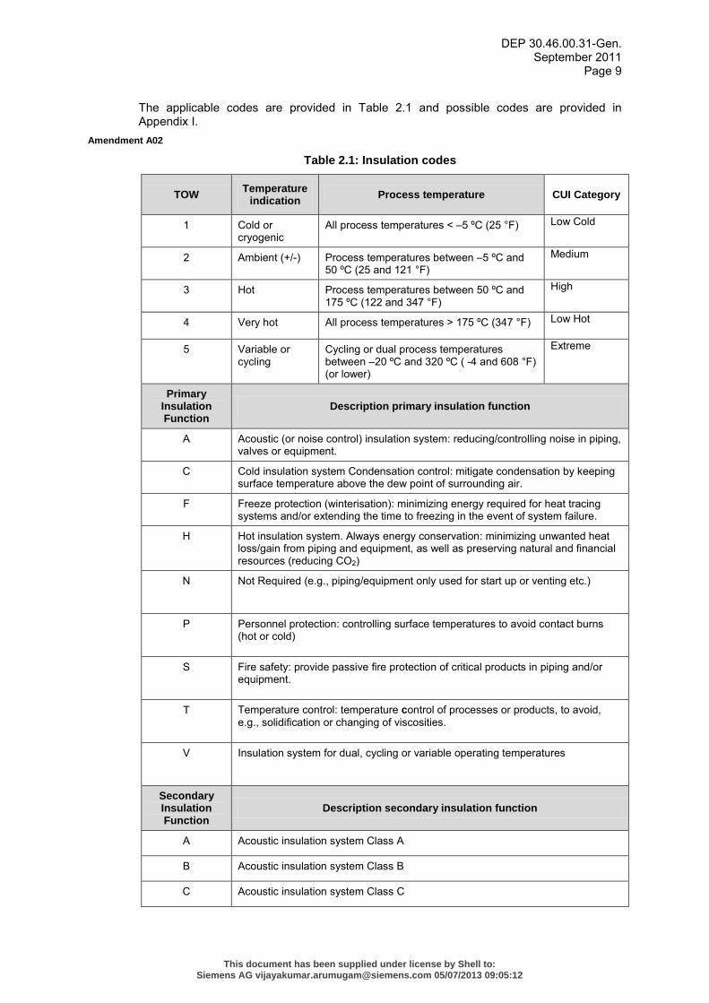
The applicable codes are provided in Table 2.1 and possible codes are provided in Appendix I.
Amendment A02
Table 2.1: Insulation codes
TOW Temperature indication Process temperature CUI Category
1 Cold or cryogenic
All process temperatures < –5 ºC (25 °F) Low Cold
2 Ambient (+/-) Process temperatures between –5 ºC and 50 ºC (25 and 121 °F)
Medium
3 Hot Process temperatures between 50 ºC and 175 ºC (122 and 347 °F)
High
4 Very hot All process temperatures > 175 ºC (347 °F) Low Hot
5 Variable or cycling
Cycling or dual process temperatures between –20 ºC and 320 ºC ( -4 and 608 °F) (or lower)
Extreme
Primary Insulation Function
Description primary insulation function
A Acoustic (or noise control) insulation system: reducing/controlling noise in piping, valves or equipment.
C Cold insulation system Condensation control: mitigate condensation by keeping surface temperature above the dew point of surrounding air.
F Freeze protection (winterisation): minimizing energy required for heat tracing systems and/or extending the time to freezing in the event of system failure.
H Hot insulation system. Always energy conservation: minimizing unwanted heat loss/gain from piping and equipment, as well as preserving natural and financial resources (reducing CO2)
N Not Required (e.g., piping/equipment only used for start up or venting etc.)
P Personnel protection: controlling surface temperatures to avoid contact burns (hot or cold)
S Fire safety: provide passive fire protection of critical products in piping and/or equipment.
T Temperature control: temperature control of processes or products, to avoid, e.g., solidification or changing of viscosities.
V Insulation system for dual, cycling or variable operating temperatures
Secondary Insulation Function
Description secondary insulation function
A Acoustic insulation system Class A
B Acoustic insulation system Class B
C Acoustic insulation system Class C
This document has been supplied under license by Shell to:Siemens AG [email protected] 05/07/2013 09:05:12
DEP 30.46.00.31-Gen. September 2011
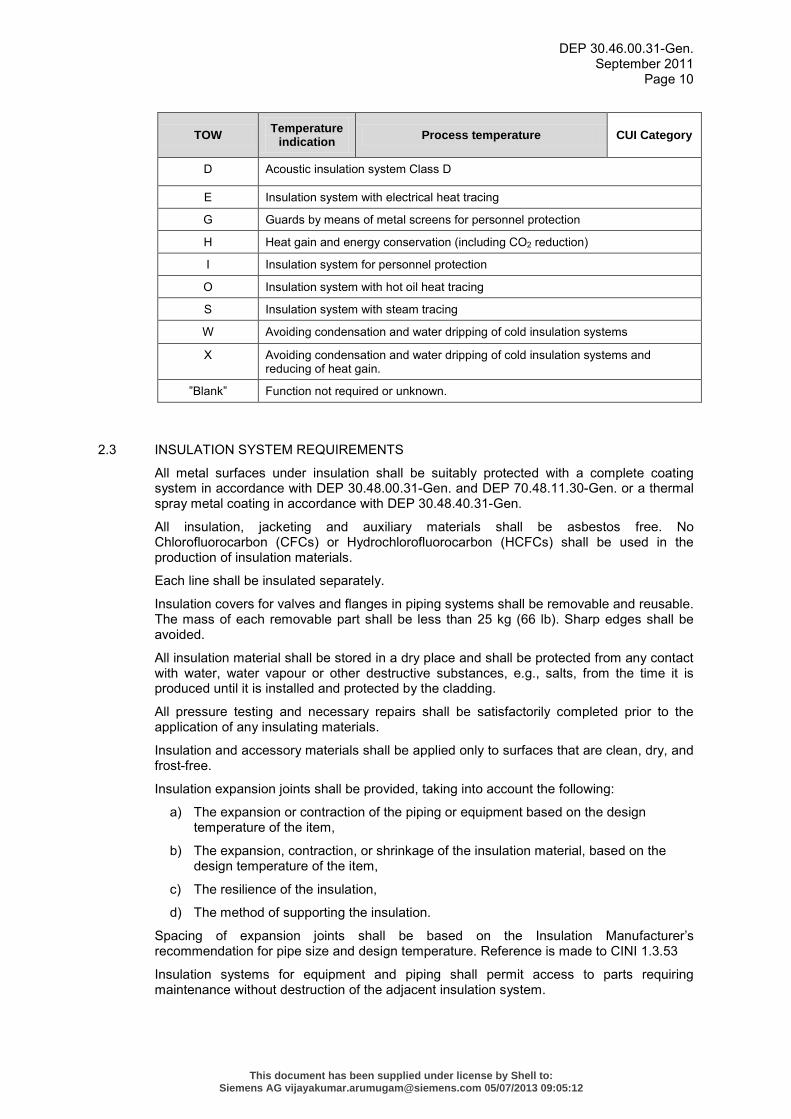
Page 10
TOW Temperature indication Process temperature CUI Category
D Acoustic insulation system Class D
E Insulation system with electrical heat tracing
G Guards by means of metal screens for personnel protection
H Heat gain and energy conservation (including CO2 reduction)
I Insulation system for personnel protection
O Insulation system with hot oil heat tracing
S Insulation system with steam tracing
W Avoiding condensation and water dripping of cold insulation systems
X Avoiding condensation and water dripping of cold insulation systems and reducing of heat gain.
”Blank” Function not required or unknown.
2.3 INSULATION SYSTEM REQUIREMENTS
All metal surfaces under insulation shall be suitably protected with a complete coating system in accordance with DEP 30.48.00.31-Gen. and DEP 70.48.11.30-Gen. or a thermal spray metal coating in accordance with DEP 30.48.40.31-Gen.
All insulation, jacketing and auxiliary materials shall be asbestos free. No Chlorofluorocarbon (CFCs) or Hydrochlorofluorocarbon (HCFCs) shall be used in the production of insulation materials.
Each line shall be insulated separately.
Insulation covers for valves and flanges in piping systems shall be removable and reusable. The mass of each removable part shall be less than 25 kg (66 lb). Sharp edges shall be avoided.
All insulation material shall be stored in a dry place and shall be protected from any contact with water, water vapour or other destructive substances, e.g., salts, from the time it is produced until it is installed and protected by the cladding.
All pressure testing and necessary repairs shall be satisfactorily completed prior to the application of any insulating materials.
Insulation and accessory materials shall be applied only to surfaces that are clean, dry, and frost-free.
Insulation expansion joints shall be provided, taking into account the following:
a) The expansion or contraction of the piping or equipment based on the design temperature of the item,
b) The expansion, contraction, or shrinkage of the insulation material, based on the design temperature of the item,
c) The resilience of the insulation,
d) The method of supporting the insulation.
Spacing of expansion joints shall be based on the Insulation Manufacturer’s recommendation for pipe size and design temperature. Reference is made to CINI 1.3.53
Insulation systems for equipment and piping shall permit access to parts requiring maintenance without destruction of the adjacent insulation system.
This document has been supplied under license by Shell to:Siemens AG [email protected] 05/07/2013 09:05:12
DEP 30.46.00.31-Gen. September 2011
Page 11
When dual layer insulation systems, employing different insulation materials are used for combined thermal and noise control, the acoustic insulation shall be installed as the outer layer.
All materials shall be supported by test certificates from a qualified laboratory and/or test reports. These tests shall be carried out in accordance with the applicable test method as defined in (3) and (4) of this DEP.
Insulation collars, if not provided by the Equipment Vendor shall be notified and communicated to the Principal and shall be fitted to avoid water ingress.
Insulation adjacent to flanges in piping and equipment shall be terminated to allow removal of bolts without damage to that insulation. Bolt clearance from the flange to the insulation jacketing shall be at least the bolt length plus an additional 30 mm (1⅛ in). If hydraulic bolt tension or torque equipment is used, a greater bolt clearance may be required.
The termination of the jacketing shall be water tight. In metal jacketing drain holes shall be provided at the lowest point to allow drainage of condense water that may have entered the insulation system.
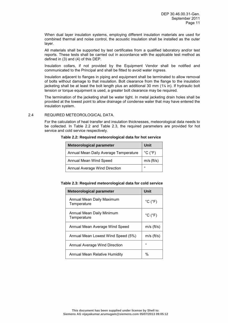
2.4 REQUIRED METEOROLOGICAL DATA.
For the calculation of heat transfer and insulation thicknesses, meteorological data needs to be collected. In Table 2.2 and Table 2.3, the required parameters are provided for hot service and cold service respectively.
Table 2.2: Required meteorological data for hot service
Meteorological parameter Unit
Annual Mean Daily Average Temperature °C (°F)
Annual Mean Wind Speed m/s (ft/s)
Annual Average Wind Direction °
Table 2.3: Required meteorological data for cold service
Meteorological parameter Unit
Annual Mean Daily Maximum Temperature °C (°F)
Annual Mean Daily Minimum Temperature °C (°F)
Annual Mean Average Wind Speed m/s (ft/s)
Annual Mean Lowest Wind Speed (5%) m/s (ft/s)
Annual Average Wind Direction °
Annual Mean Relative Humidity %
This document has been supplied under license by Shell to:Siemens AG [email protected] 05/07/2013 09:05:12
DEP 30.46.00.31-Gen. September 2011
Page 12
3. HOT INSULATION SYSTEMS
3.1 ENGINEERING DESIGN
Hot insulation systems are to be defined as insulation systems for pipelines and equipment that operate above ambient temperatures.
In hot service, thermal insulation is required for:
a) Thermal conservation of equipment and piping if economically justified;
b) Temperature control of processes or products e.g., to avoid solidification or too high viscosity possibly combined with trace heating;
c) Personnel protection, e.g. on surfaces with a temperature of 250°C (482°F) or higher if these surfaces present a danger (between 60°C (140°F) and 250°C (482°F) open mesh guards are preferably used).
Piping and equipment provided with internal refractory shall not be insulated.
A combination of no more than two different insulating materials shall be used.
Insulative coatings shall not be used without approval of the Principal and shall demonstrate the ability to provide conductive insulation capability across the thickness of the material exclusive of any boundary layer effects.
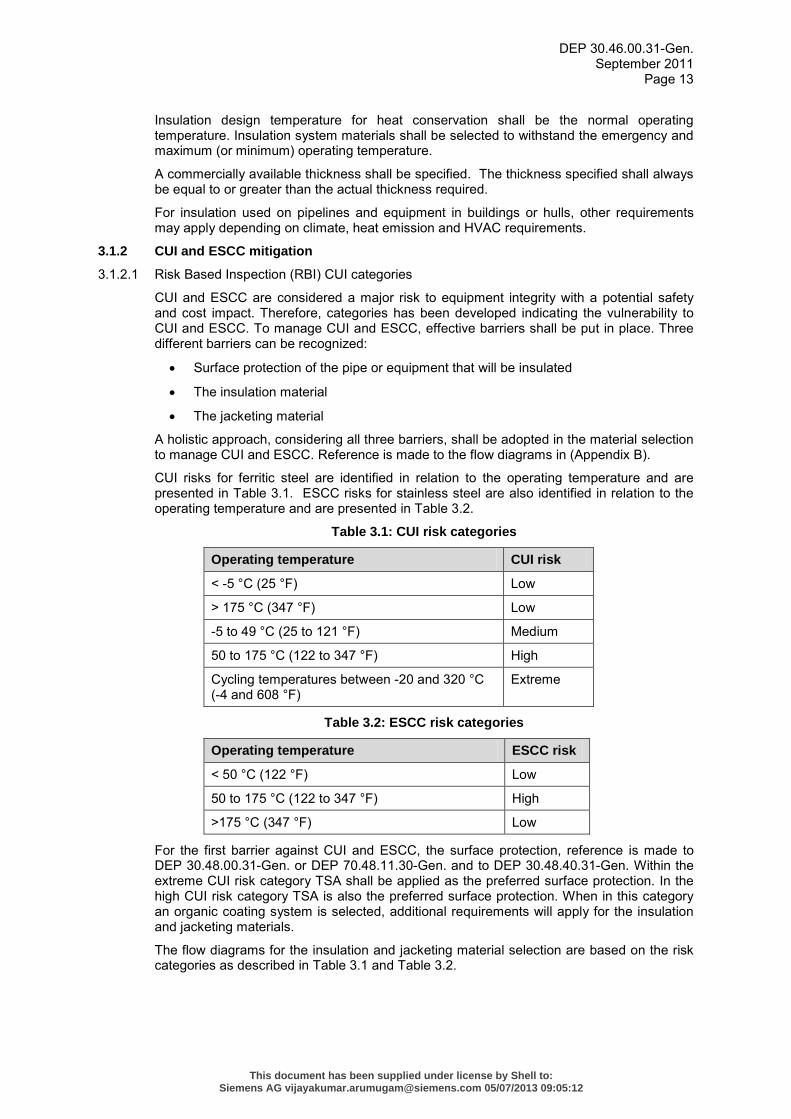
3.1.1 Insulation thickness calculations
For hot services, the optimum economical insulation thickness shall be calculated according to the minimum total cost method. For a given thickness, the total cost is the sum of the investment and maintenance of the insulation system and the cost of energy losses through the insulation as shown in Figure 3.1. Tables shall be created for each insulation system and each project site similar to the referenced tables with various input parameters provided in (Appendix E). These calculations shall be based on VDI 2055.
Figure 3.1: Minimum total cost method for insulation thickness design
In some cases a separate insulation thickness evaluation is required to fulfill specific process, safety, environmental or technical requirements. The following additional calculations may apply:
a) The temperature changes of a flowing fluid in an insulated and an uninsulated pipeline,
b) The time in which a stagnant fluid in an insulated or an uninsulated pipeline changes to a certain temperature,
c) The temperature change of a stagnant fluid in an insulated or uninsulated pipeline in a certain time,
d) The insulation thickness for a pipeline to limit the temperature change of a flowing fluid to a certain value.
This document has been supplied under license by Shell to:Siemens AG [email protected] 05/07/2013 09:05:12
DEP 30.46.00.31-Gen. September 2011
Page 13
Insulation design temperature for heat conservation shall be the normal operating temperature. Insulation system materials shall be selected to withstand the emergency and maximum (or minimum) operating temperature.
A commercially available thickness shall be specified. The thickness specified shall always be equal to or greater than the actual thickness required.
For insulation used on pipelines and equipment in buildings or hulls, other requirements may apply depending on climate, heat emission and HVAC requirements.
3.1.2 CUI and ESCC mitigation
3.1.2.1 Risk Based Inspection (RBI) CUI categories
CUI and ESCC are considered a major risk to equipment integrity with a potential safety and cost impact. Therefore, categories has been developed indicating the vulnerability to CUI and ESCC. To manage CUI and ESCC, effective barriers shall be put in place. Three different barriers can be recognized:
• Surface protection of the pipe or equipment that will be insulated
• The insulation material
• The jacketing material
A holistic approach, considering all three barriers, shall be adopted in the material selection to manage CUI and ESCC. Reference is made to the flow diagrams in (Appendix B).
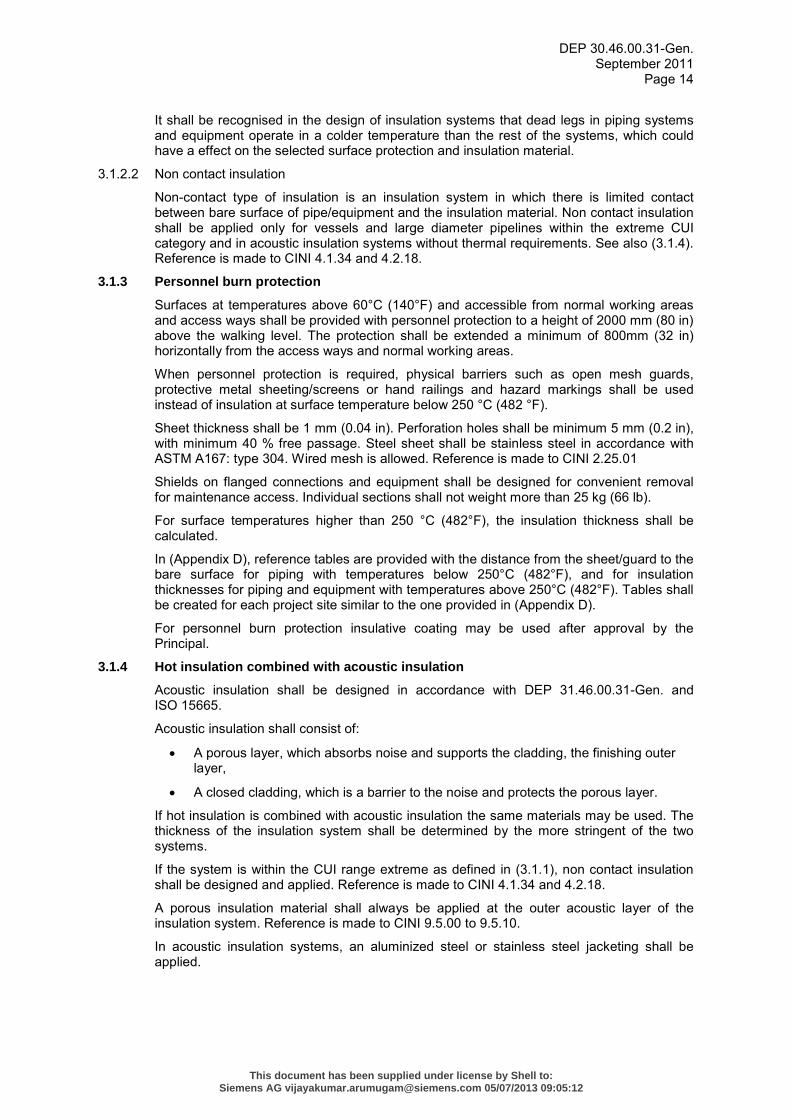
CUI risks for ferritic steel are identified in relation to the operating temperature and are presented in Table 3.1. ESCC risks for stainless steel are also identified in relation to the operating temperature and are presented in Table 3.2.
Table 3.1: CUI risk categories
Operating temperature CUI risk
< -5 °C (25 °F) Low
> 175 °C (347 °F) Low
-5 to 49 °C (25 to 121 °F) Medium
50 to 175 °C (122 to 347 °F) High
Cycling temperatures between -20 and 320 °C (-4 and 608 °F)
Extreme
Table 3.2: ESCC risk categories
Operating temperature ESCC risk
< 50 °C (122 °F) Low
50 to 175 °C (122 to 347 °F) High
>175 °C (347 °F) Low
For the first barrier against CUI and ESCC, the surface protection, reference is made to DEP 30.48.00.31-Gen. or DEP 70.48.11.30-Gen. and to DEP 30.48.40.31-Gen. Within the extreme CUI risk category TSA shall be applied as the preferred surface protection. In the high CUI risk category TSA is also the preferred surface protection. When in this category an organic coating system is selected, additional requirements will apply for the insulation and jacketing materials.
The flow diagrams for the insulation and jacketing material selection are based on the risk categories as described in Table 3.1 and Table 3.2.
This document has been supplied under license by Shell to:Siemens AG [email protected] 05/07/2013 09:05:12
DEP 30.46.00.31-Gen. September 2011
Page 14
It shall be recognised in the design of insulation systems that dead legs in piping systems and equipment operate in a colder temperature than the rest of the systems, which could have a effect on the selected surface protection and insulation material.
3.1.2.2 Non contact insulation
Non-contact type of insulation is an insulation system in which there is limited contact between bare surface of pipe/equipment and the insulation material. Non contact insulation shall be applied only for vessels and large diameter pipelines within the extreme CUI category and in acoustic insulation systems without thermal requirements. See also (3.1.4). Reference is made to CINI 4.1.34 and 4.2.18.
3.1.3 Personnel burn protection
Surfaces at temperatures above 60°C (140°F) and accessible from normal working areas and access ways shall be provided with personnel protection to a height of 2000 mm (80 in) above the walking level. The protection shall be extended a minimum of 800mm (32 in) horizontally from the access ways and normal working areas.
When personnel protection is required, physical barriers such as open mesh guards, protective metal sheeting/screens or hand railings and hazard markings shall be used instead of insulation at surface temperature below 250 °C (482 °F).
Sheet thickness shall be 1 mm (0.04 in). Perforation holes shall be minimum 5 mm (0.2 in), with minimum 40 % free passage. Steel sheet shall be stainless steel in accordance with ASTM A167: type 304. Wired mesh is allowed. Reference is made to CINI 2.25.01
Shields on flanged connections and equipment shall be designed for convenient removal for maintenance access. Individual sections shall not weight more than 25 kg (66 lb).
For surface temperatures higher than 250 °C (482°F), the insulation thickness shall be calculated.
In (Appendix D), reference tables are provided with the distance from the sheet/guard to the bare surface for piping with temperatures below 250°C (482°F), and for insulation thicknesses for piping and equipment with temperatures above 250°C (482°F). Tables shall be created for each project site similar to the one provided in (Appendix D).
For personnel burn protection insulative coating may be used after approval by the Principal.
3.1.4 Hot insulation combined with acoustic insulation
Acoustic insulation shall be designed in accordance with DEP 31.46.00.31-Gen. and ISO 15665.
Acoustic insulation shall consist of:
• A porous layer, which absorbs noise and supports the cladding, the finishing outer layer,
• A closed cladding, which is a barrier to the noise and protects the porous layer.
If hot insulation is combined with acoustic insulation the same materials may be used. The thickness of the insulation system shall be determined by the more stringent of the two systems.
If the system is within the CUI range extreme as defined in (3.1.1), non contact insulation shall be designed and applied. Reference is made to CINI 4.1.34 and 4.2.18.
A porous insulation material shall always be applied at the outer acoustic layer of the insulation system. Reference is made to CINI 9.5.00 to 9.5.10.
In acoustic insulation systems, an aluminized steel or stainless steel jacketing shall be applied.
This document has been supplied under license by Shell to:Siemens AG [email protected] 05/07/2013 09:05:12
DEP 30.46.00.31-Gen. September 2011
Page 15
3.1.5 Hot insulation combined with fire protection
If fire protection of pipelines or equipment is required, cellular glass shall be used as the insulation material. Alternative materials for fire protections may be used after approval of the Principal.
If fire protection of pipelines or equipment is required, only aluminized steel or stainless steel jacketing material shall be used.
3.1.6 Hot insulation combined with heat tracing
For insulation systems combined with heat tracing, a separate calculation shall be made to determine the required insulation thickness. For the design, reference is made to DEP 31.38.30.11-Gen. and DEP 33.68.30.32-Gen. Also, reference is made to CINI 4.1.04.
3.2 MATERIALS
For all materials, documentation such as certificates of origin, quality control records, product information and safety material data sheets shall be made available and shall indicate HSE-related hazards during application, use, removal and disposal.
3.2.1 Material selection
For the insulation and jacketing material selection, reference is made to the flow diagram in (Appendix B).
3.2.2 Insulation materials
Only the materials provided in this DEP are allowed for use. Other materials require approval from the Principal.
Extruded polystyrene foam shall not be used.
Glass wool insulation shall not be used.
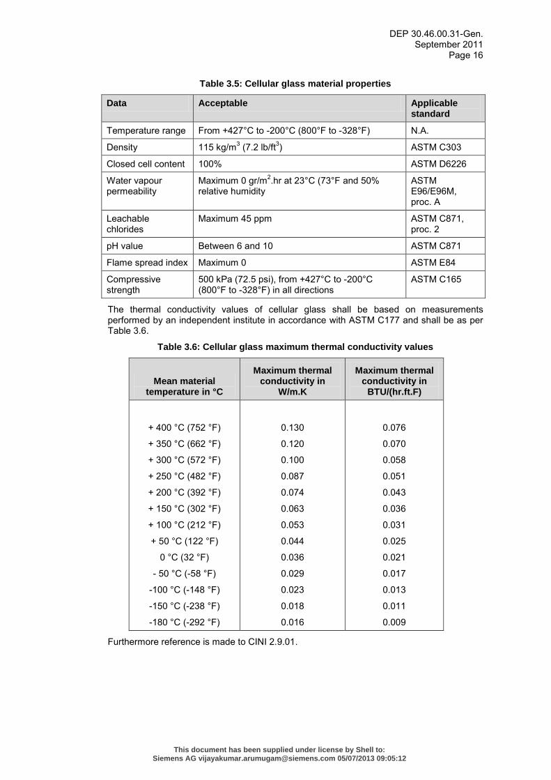
3.2.2.1 Cellular glass
Cellular glass shall be finished with weather resistant bitumen-based vapour barrier (cell filler) in cold climates to prevent frost damage.
Cellular glass shall be used in insulation collars and for fire protection purposes. For details on insulation collars, reference is made to standard drawing S.10.056.
Cellular glass material properties shall comply with the requirements in Table 3.5. The material properties shall be demonstrated by the applicable test standard provided in Table 3.5.
This document has been supplied under license by Shell to:Siemens AG [email protected] 05/07/2013 09:05:12
DEP 30.46.00.31-Gen. September 2011
Page 16
Table 3.5: Cellular glass material properties
Data Acceptable Applicable standard
Temperature range From +427°C to -200°C (800°F to -328°F) N.A.
Density 115 kg/m3 (7.2 lb/ft3) ASTM C303
Closed cell content 100% ASTM D6226
Water vapour permeability
Maximum 0 gr/m2.hr at 23°C (73°F and 50% relative humidity
ASTM E96/E96M, proc. A
Leachable chlorides
Maximum 45 ppm ASTM C871, proc. 2
pH value Between 6 and 10 ASTM C871
Flame spread index Maximum 0 ASTM E84
Compressive strength
500 kPa (72.5 psi), from +427°C to -200°C (800°F to -328°F) in all directions
ASTM C165
The thermal conductivity values of cellular glass shall be based on measurements performed by an independent institute in accordance with ASTM C177 and shall be as per Table 3.6.
Table 3.6: Cellular glass maximum thermal conductivity values
Mean material temperature in °C
Maximum thermal conductivity in
W/m.K
Maximum thermal conductivity in
BTU/(hr.ft.F)
+ 400 °C (752 °F)
+ 350 °C (662 °F)
+ 300 °C (572 °F)
+ 250 °C (482 °F)
+ 200 °C (392 °F)
+ 150 °C (302 °F)
+ 100 °C (212 °F)
+ 50 °C (122 °F)
0 °C (32 °F)
- 50 °C (-58 °F)
-100 °C (-148 °F)
-150 °C (-238 °F)
-180 °C (-292 °F)
0.130
0.120
0.100
0.087
0.074
0.063
0.053
0.044
0.036
0.029
0.023
0.018
0.016
0.076
0.070
0.058
0.051
0.043
0.036
0.031
0.025
0.021
0.017
0.013
0.011
0.009
Furthermore reference is made to CINI 2.9.01.
This document has been supplied under license by Shell to:Siemens AG [email protected] 05/07/2013 09:05:12
DEP 30.46.00.31-Gen. September 2011
Page 17
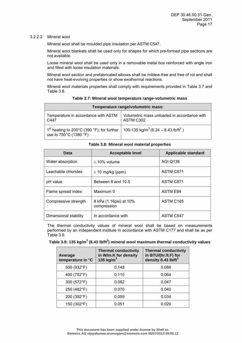
3.2.2.2 Mineral wool
Mineral wool shall be moulded pipe insulation per ASTM C547.
Mineral wool blankets shall be used only for shapes for which pre-formed pipe sections are not available.
Loose mineral wool shall be used only in a removable metal box reinforced with angle iron and filled with loose insulation materials.
Mineral wool section and prefabricated elbows shall be mildew-free and free of rot and shall not have heat-evolving properties or show exothermal reactions.
Mineral wool materials properties shall comply with requirements provided in Table 3.7 and Table 3.8.
Table 3.7: Mineral wool temperature range-volumetric mass
Temperature range/volumetric mass:
Temperature in accordance with ASTM C447
Volumetric mass unloaded in accordance with ASTM C302
1st heating to 200°C (390 °F); for further use to 750°C (1380 °F)
100-135 kg/m3 (6.24 – 8.43.lb/ft3 )
Table 3.8: Mineral wool material properties
Data Acceptable level Applicable standard
Water absorption ≤ 10% volume AGI Q136
Leachable chlorides ≤ 10 mg/kg (ppm) ASTM C871
pH value Between 6 and 10.5 ASTM C871
Flame spread index Maximum 0 ASTM E84
Compressive strength 8 kPa (1.16psi) at 10% compression
ASTM C165
Dimensional stability In accordance with ASTM C547
The thermal conductivity values of mineral wool shall be based on measurements performed by an independent institute in accordance with ASTM C177 and shall be as per Table 3.9.
Table 3.9: 135 kg/m3 (8.43 lb/ft3) mineral wool maximum thermal conductivity values
Average temperature in °C
Thermal conductivity in W/m.K for density 135 kg/m3
Thermal conductivity in BTU/(hr.ft.F) for density 8.43 lb/ft3
500 (932°F) 0.148 0.086
400 (752°F) 0.110 0.064
300 (572°F) 0.082 0.047
250 (482°F) 0.070 0.040
200 (392°F) 0.059 0.034
150 (302°F) 0.051 0.029
This document has been supplied under license by Shell to:Siemens AG [email protected] 05/07/2013 09:05:12
DEP 30.46.00.31-Gen. September 2011
Page 18
Average temperature in °C
Thermal conductivity in W/m.K for density 135 kg/m3
Thermal conductivity in BTU/(hr.ft.F) for density 8.43 lb/ft3
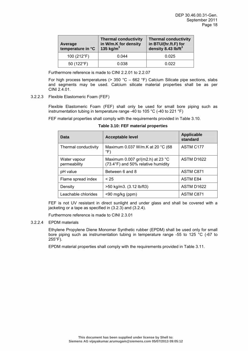
100 (212°F) 0.044 0.025
50 (122°F) 0.038 0.022
Furthermore reference is made to CINI 2.2.01 to 2.2.07
For high process temperatures (> 350 °C – 662 °F) Calcium Silicate pipe sections, slabs and segments may be used. Calcium silicate material properties shall be as per CINI 2.4.01.
3.2.2.3 Flexible Elastomeric Foam (FEF)
Flexible Elastomeric Foam (FEF) shall only be used for small bore piping such as instrumentation tubing in temperature range -40 to 105 °C (-40 to 221 °F)
FEF material properties shall comply with the requirements provided in Table 3.10.
Table 3.10: FEF material properties
Data Acceptable level Applicable standard
Thermal conductivity Maximum 0.037 W/m.K at 20 °C (68 °F)
ASTM C177
Water vapour permeability
Maximum 0.007 gr/(m2.h) at 23 °C (73.4°F) and 50% relative humidity
ASTM D1622
pH value Between 6 and 8 ASTM C871
Flame spread index < 25 ASTM E84
Density >50 kg/m3. (3.12 lb/ft3) ASTM D1622
Leachable chlorides <90 mg/kg (ppm) ASTM C871
FEF is not UV resistant in direct sunlight and under glass and shall be covered with a jacketing or a tape as specified in (3.2.3) and (3.2.4).
Furthermore reference is made to CINI 2.3.01
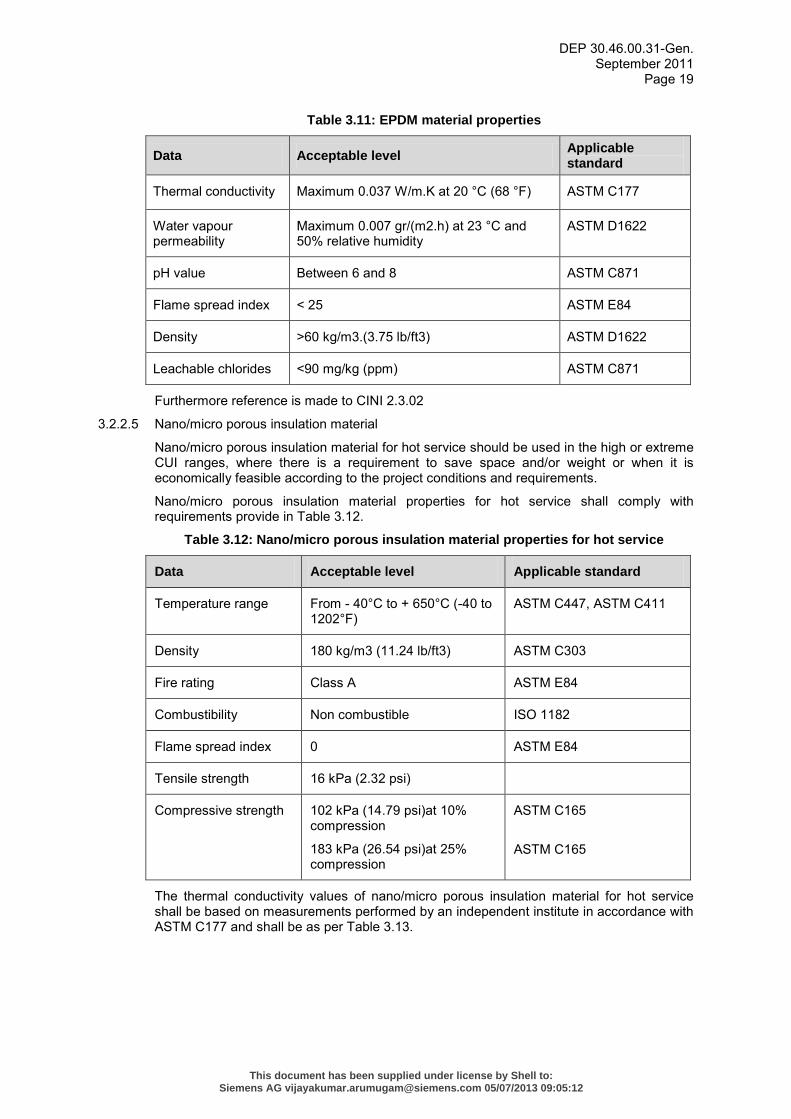
3.2.2.4 EPDM materials
Ethylene Propylene Diene Monomer Synthetic rubber (EPDM) shall be used only for small bore piping such as instrumentation tubing in temperature range -55 to 125 °C (-67 to 255°F).
EPDM material properties shall comply with the requirements provided in Table 3.11.
This document has been supplied under license by Shell to:Siemens AG [email protected] 05/07/2013 09:05:12
DEP 30.46.00.31-Gen. September 2011
Page 19
Table 3.11: EPDM material properties
Data Acceptable level Applicable standard
Thermal conductivity Maximum 0.037 W/m.K at 20 °C (68 °F) ASTM C177
Water vapour permeability
Maximum 0.007 gr/(m2.h) at 23 °C and 50% relative humidity
ASTM D1622
pH value Between 6 and 8 ASTM C871
Flame spread index < 25 ASTM E84
Density >60 kg/m3.(3.75 lb/ft3) ASTM D1622
Leachable chlorides <90 mg/kg (ppm) ASTM C871
Furthermore reference is made to CINI 2.3.02
3.2.2.5 Nano/micro porous insulation material
Nano/micro porous insulation material for hot service should be used in the high or extreme CUI ranges, where there is a requirement to save space and/or weight or when it is economically feasible according to the project conditions and requirements.
Nano/micro porous insulation material properties for hot service shall comply with requirements provide in Table 3.12.
Table 3.12: Nano/micro porous insulation material properties for hot service
Data Acceptable level Applicable standard
Temperature range From - 40°C to + 650°C (-40 to 1202°F)
ASTM C447, ASTM C411
Density 180 kg/m3 (11.24 lb/ft3) ASTM C303
Fire rating Class A ASTM E84
Combustibility Non combustible ISO 1182
Flame spread index 0 ASTM E84
Tensile strength 16 kPa (2.32 psi)
Compressive strength 102 kPa (14.79 psi)at 10% compression
183 kPa (26.54 psi)at 25% compression
ASTM C165
ASTM C165
The thermal conductivity values of nano/micro porous insulation material for hot service shall be based on measurements performed by an independent institute in accordance with ASTM C177 and shall be as per Table 3.13.
This document has been supplied under license by Shell to:Siemens AG [email protected] 05/07/2013 09:05:12
DEP 30.46.00.31-Gen. September 2011
Page 20
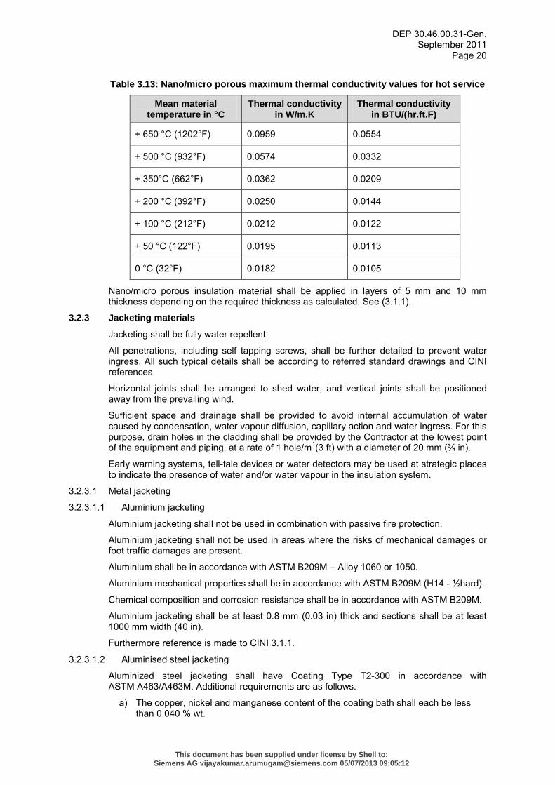
Table 3.13: Nano/micro porous maximum thermal conductivity values for hot service
Mean material temperature in °C
Thermal conductivity in W/m.K
Thermal conductivity in BTU/(hr.ft.F)
+ 650 °C (1202°F) 0.0959 0.0554
+ 500 °C (932°F) 0.0574 0.0332
+ 350°C (662°F) 0.0362 0.0209
+ 200 °C (392°F) 0.0250 0.0144
+ 100 °C (212°F) 0.0212 0.0122
+ 50 °C (122°F) 0.0195 0.0113
0 °C (32°F) 0.0182 0.0105
Nano/micro porous insulation material shall be applied in layers of 5 mm and 10 mm thickness depending on the required thickness as calculated. See (3.1.1).
3.2.3 Jacketing materials
Jacketing shall be fully water repellent.
All penetrations, including self tapping screws, shall be further detailed to prevent water ingress. All such typical details shall be according to referred standard drawings and CINI references.
Horizontal joints shall be arranged to shed water, and vertical joints shall be positioned away from the prevailing wind.
Sufficient space and drainage shall be provided to avoid internal accumulation of water caused by condensation, water vapour diffusion, capillary action and water ingress. For this purpose, drain holes in the cladding shall be provided by the Contractor at the lowest point of the equipment and piping, at a rate of 1 hole/m1(3 ft) with a diameter of 20 mm (¾ in).
Early warning systems, tell-tale devices or water detectors may be used at strategic places to indicate the presence of water and/or water vapour in the insulation system.
3.2.3.1 Metal jacketing
3.2.3.1.1 Aluminium jacketing
Aluminium jacketing shall not be used in combination with passive fire protection.
Aluminium jacketing shall not be used in areas where the risks of mechanical damages or foot traffic damages are present.
Aluminium shall be in accordance with ASTM B209M – Alloy 1060 or 1050.
Aluminium mechanical properties shall be in accordance with ASTM B209M (H14 - ½hard).
Chemical composition and corrosion resistance shall be in accordance with ASTM B209M.
Aluminium jacketing shall be at least 0.8 mm (0.03 in) thick and sections shall be at least 1000 mm width (40 in).
Furthermore reference is made to CINI 3.1.1.
3.2.3.1.2 Aluminised steel jacketing
Aluminized steel jacketing shall have Coating Type T2-300 in accordance with ASTM A463/A463M. Additional requirements are as follows.
a) The copper, nickel and manganese content of the coating bath shall each be less than 0.040 % wt.
This document has been supplied under license by Shell to:Siemens AG [email protected] 05/07/2013 09:05:12
DEP 30.46.00.31-Gen. September 2011
Page 21
b) All cut edges of the aluminized steel Type T1 shall be coated to ensure corrosion protection.
The aluminium coating shall not crack, flake or peel during required mechanical processing.
Aluminized steel jacketing shall not be used in climates where salt-containing condensation can evaporate due to high daytime temperatures.
The aluminized steel jacketing mechanical properties, chemical composition and corrosion resistance shall be in accordance with ASTM A463/A463M.
Aluminized steel jacketing shall be at least 0.8 mm (0.03 in) thick and sections shall be at least 500 mm width (20 in).
Furthermore reference is made to CINI 3.1.2.
3.2.3.1.3 Stainless steel jacketing
Stainless steel Type 304 or Type 316 in accordance with ASTM A167 shall be used.
Mechanical and chemical properties and corrosion resistance shall be in accordance with ASTM A167.
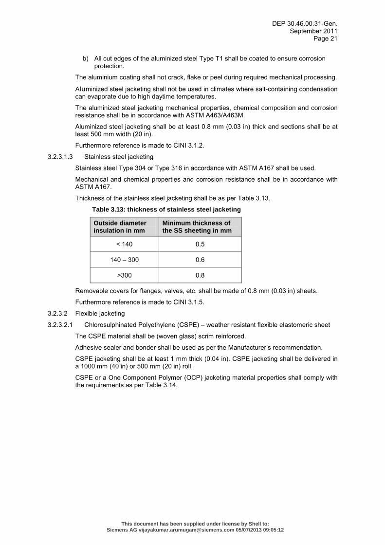
Thickness of the stainless steel jacketing shall be as per Table 3.13.
Table 3.13: thickness of stainless steel jacketing
Outside diameter insulation in mm
Minimum thickness of the SS sheeting in mm
< 140 0.5
140 – 300 0.6
>300 0.8
Removable covers for flanges, valves, etc. shall be made of 0.8 mm (0.03 in) sheets.
Furthermore reference is made to CINI 3.1.5.
3.2.3.2 Flexible jacketing
3.2.3.2.1 Chlorosulphinated Polyethylene (CSPE) – weather resistant flexible elastomeric sheet
The CSPE material shall be (woven glass) scrim reinforced.
Adhesive sealer and bonder shall be used as per the Manufacturer’s recommendation.
CSPE jacketing shall be at least 1 mm thick (0.04 in). CSPE jacketing shall be delivered in a 1000 mm (40 in) or 500 mm (20 in) roll.
CSPE or a One Component Polymer (OCP) jacketing material properties shall comply with the requirements as per Table 3.14.
This document has been supplied under license by Shell to:Siemens AG [email protected] 05/07/2013 09:05:12
DEP 30.46.00.31-Gen. September 2011
Page 22
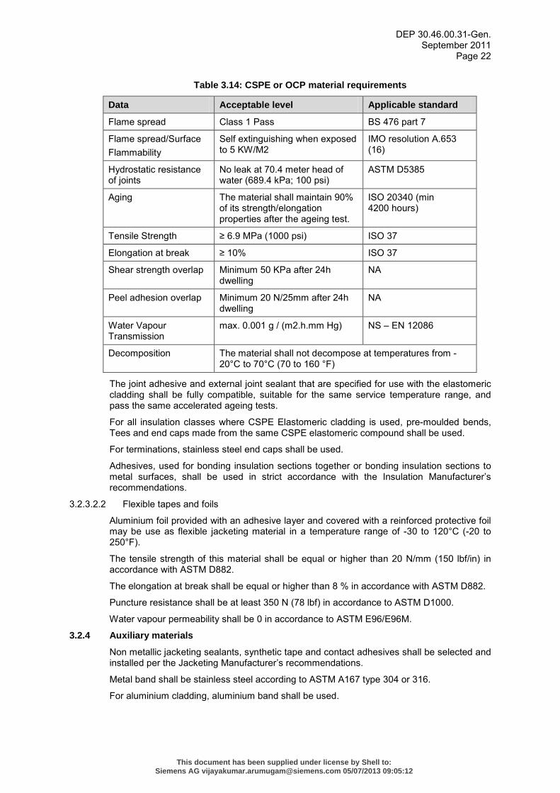
Table 3.14: CSPE or OCP material requirements
Data Acceptable level Applicable standard
Flame spread Class 1 Pass BS 476 part 7
Flame spread/Surface Flammability
Self extinguishing when exposed to 5 KW/M2
IMO resolution A.653 (16)
Hydrostatic resistance of joints
No leak at 70.4 meter head of water (689.4 kPa; 100 psi)
ASTM D5385
Aging The material shall maintain 90% of its strength/elongation properties after the ageing test.
ISO 20340 (min 4200 hours)
Tensile Strength ≥ 6.9 MPa (1000 psi) ISO 37
Elongation at break ≥ 10% ISO 37
Shear strength overlap Minimum 50 KPa after 24h dwelling
NA
Peel adhesion overlap Minimum 20 N/25mm after 24h dwelling
NA
Water Vapour Transmission
max. 0.001 g / (m2.h.mm Hg) NS – EN 12086
Decomposition The material shall not decompose at temperatures from -20°C to 70°C (70 to 160 °F)
The joint adhesive and external joint sealant that are specified for use with the elastomeric cladding shall be fully compatible, suitable for the same service temperature range, and pass the same accelerated ageing tests.
For all insulation classes where CSPE Elastomeric cladding is used, pre-moulded bends, Tees and end caps made from the same CSPE elastomeric compound shall be used.
For terminations, stainless steel end caps shall be used.
Adhesives, used for bonding insulation sections together or bonding insulation sections to metal surfaces, shall be used in strict accordance with the Insulation Manufacturer’s recommendations.
3.2.3.2.2 Flexible tapes and foils
Aluminium foil provided with an adhesive layer and covered with a reinforced protective foil may be use as flexible jacketing material in a temperature range of -30 to 120°C (-20 to 250°F).
The tensile strength of this material shall be equal or higher than 20 N/mm (150 lbf/in) in accordance with ASTM D882.
The elongation at break shall be equal or higher than 8 % in accordance with ASTM D882.
Puncture resistance shall be at least 350 N (78 lbf) in accordance to ASTM D1000.
Water vapour permeability shall be 0 in accordance to ASTM E96/E96M.
3.2.4 Auxiliary materials
Non metallic jacketing sealants, synthetic tape and contact adhesives shall be selected and installed per the Jacketing Manufacturer’s recommendations.
Metal band shall be stainless steel according to ASTM A167 type 304 or 316.
For aluminium cladding, aluminium band shall be used.
This document has been supplied under license by Shell to:Siemens AG [email protected] 05/07/2013 09:05:12
DEP 30.46.00.31-Gen. September 2011
Page 23
For temperature < 300°C (572°F) a one component polysiloxane based permanent flexible sealer shall be used. For temperatures > 300°C (572°F), a sodium silicate based sealer shall be used.
Wire mesh shall be stainless steel according to ASTM A167 type 304 or 316. Wire diameter shall be 3 mm (1/8 in) and the mesh dimensions 50x50 mm (2x2 in).
Binding wire shall be stainless steel according to ASTM A167 type 304 or 316, 1 mm (0.04 in) thick.
Adhesive synthetic tape shall be glass fibre reinforced. The adhesiveness shall be 200 gr/25 mm2 (0.44 lb/0.038 in2).
Self tapping screws shall be in accordance with the jacketing material 4.8 x 13 mm (ISO 1481 type C).
Furthermore reference is made to CINI 2.25.01
3.3 APPLICATION
3.3.1 General
Applicator training and site supervision shall be provided for all insulation and jacketing applications. In the case of non metallic jacketing, on-site Jacket Manufacturer supervision is required.
Provisions shall be made to ensure that the materials can also be fitted under poor weather conditions. Prior to application of the finishing material, the insulation material shall be dry.
Insulation activities, including the jacketing, shall be completed in one day. Exposed insulation material shall be properly covered for water and moisture ingress.
Nameplates, reference- and measuring points shall remain visible at all times. Discharge and air relief valves shall remain operable.
The edges of the recesses shall have a weatherproof finish.
Insulation through walls, partitions and floors shall be uninterrupted and of uniform thickness.
A minimum space of 25 mm (1 in). shall be observed between the insulation finishing and the adjacent surfaces. In case of problems, the insulation thickness may be adapted locally, after approval from the Principal.
Stiffeners, rings, girders etc., attached to insulated columns, tanks, vessels and heat exchangers, shall have the same insulation thickness as the equipment. Flanges, valves, and expansion bellows shall have the same insulation thickness as the piping and equipment concerned. Reference is made to CINI 4.1.25.
Pipe insulation systems shall start at a distance 'bolt length + 30 mm (1¼ in)' from flanges to prevent damage to the insulation when opening that flange. When treaded ends are applied and/or pneumatic tools are used, the insulation shall be removed before.
Removable hot insulation around flanges, valves, etc. shall be design to withstand frequent removal and re-installation without losing its properties. The mass of each removable part shall be less than 25 kg (55 lb).
3.3.1.1 HSE in application
During application of insulation materials personnel shall be protected against dust and skin irritation.
3.3.2 Surface preparation
Ingress of rainwater and corrosive products or condensation of water vapour in the insulation may cause severe CUI and ESCC, and increases the thermal conductivity (reducing insulation values) significantly. To protect the steel from CUI and ESCC, a surface protection system shall be applied in accordance with DEP 30.48.00.31-Gen. and DEP 70.48.11.30-Gen or DEP 30.48.40.31-Gen.
This document has been supplied under license by Shell to:Siemens AG [email protected] 05/07/2013 09:05:12
DEP 30.46.00.31-Gen. September 2011
Page 24
Before the insulation work is started, the surfaces to be insulated shall be clean, dry and provided with the appropriate surface protection. Prior to the application of the insulation material the Contractor shall obtain a “released for insulation” document stating the surface is clean, dry and prepared, as required.
3.3.3 Piping details
Piping details are provided in CINI 4.1.00.
3.3.4 Valves, flanges, manholes and fittings
Hot insulation of valves, flanges, manholes and fittings in piping and removable equipment dome heads shall be provided with removable insulation covers, with rock wool on the inside, and fastened with clips. When frequent removal is required, covers shall be provided with quick release toggles that shall be locked when installed. Quick release toggles shall not be fitted in overhead lines above walkways.
Provisions shall be made to allow visible detection of flange leakages.
Typical removable covers for spectacle blind flanges in vertical and horizontal pipes are provided in accordance with CINI 4.1.31 and 4.1.32.
3.3.5 Vessels
Insulation shall be applied to the shell using the broken joint method, starting with alternate one-half and full-length curve segments or flat blocks bevelled to fit. On vertical vessels, the application shall start at the insulation support and proceed upward; and on horizontal vessels, the application shall start at one end of the vessel and proceed circumferentially and horizontally. Insulation segments shall be made as large as possible to minimize the number of joints.
Insulation for vessel heads shall be applied in the same manner as that prescribed for shells, using special factory-shaped head segments. Insulation on top heads of vertical vessels and heads for horizontal vessels shall be held in place with bands radiating from a floating ring.
Insulation shall not be required on the bottom heads of vertical vessels where insulated skirts provide adequate heat loss and fire protection. Insulation details for vessels are provided in CINI 4.3.00 and for columns in CINI 4.2.00.
3.3.6 Heat exchangers
The heat exchangers channel end flanges and shell cover flanges shall not be insulated except as required for personnel protection, in which case shielding shall be considered. Insulation details for heat exchangers are provided in CINI 4.4.00.
3.3.7 Sealing plates and insulation collars
Insulation collars, to prevent water ingress at protrusions, shall be fitted around all protruding parts of tanks, vessels and columns with operating temperatures between ambient and + 175°C (347°F) or with intermittent operation. These collars shall be executed in accordance with standard drawing S.10.056.
For flammable products, insulation collars as per S.10.056 shall be applied next to flanges in order to prevent products from entering in the insulation system.
3.3.8 Rotating equipment
Rotating equipment should not be insulated unless acoustic insulation is required. For steam turbines and boiler feed pumps insulation may be required to avoid extensive heat losses. In these cases, removable insulation mats or mattresses with glass fibre fabric finish, tailor made over the housing and fixed by lacing, is the preferred method. Insulation details for pumps are provided in CINI 4.6.01.
3.3.9 Non contact insulation
Non contact insulation shall be as per CINI 1.3.22, 4.1.34 and 4.2.18.
This document has been supplied under license by Shell to:Siemens AG [email protected] 05/07/2013 09:05:12
DEP 30.46.00.31-Gen. September 2011
Page 25
3.3.10 Tank insulation
Tank insulation shall be as per CINI 4.5.00.
Tank roofs at temperatures up to 120°C (248°F) shall not be insulated except for process requirements.
Personnel protection shall be installed on accessible areas of tank roofs where the calculated metal temperature is greater than 60°C (140°F).
If tank roofs are to be insulated for process reasons, the mechanical design shall anticipate all insulation requirements as mentioned in this DEP.
The construction of the insulation system shall be water tight and strong enough to resist high and fluctuating intermittent wind loads, such as pressure and tensile loads for a long period (25 years). In addition, the insulation system should be capable of absorbing deformation of the tank due to temperature variations, loading/unloading, etc. in such a way that the insulation jacketing remains weather-resistant.
Provisions shall be made for absorbing the expansion in the insulation system and the cladding. For the wall cladding the expansion differences between the tank wall and the insulation system shall be determined beforehand and the protrusions shall be sealed accordingly, with fixed or flexible protrusions plates, respectively.
3.3.11 CSPE application
Application details for CSPE jacketing material for piping shall be as per (Appendix H).
This document has been supplied under license by Shell to:Siemens AG [email protected] 05/07/2013 09:05:12
DEP 30.46.00.31-Gen. September 2011
Page 26
4. COLD AND DUAL INSULATION SYSTEMS
4.1 ENGINEERING DESIGN
Cold insulation systems may be defined as insulation systems for pipelines and equipment that operates below ambient temperatures.
In cold service, thermal insulation shall be required for:
• Thermal conservation of pipelines or equipment to conserve refrigeration (limit heat gain).
• To limit surface condensation and icing.
• To limit boil-off.
Cold insulation systems shall be water vapour tight.
Personnel protection for cold service is not required and shall be specified only after instruction of the Principal.
The layering of cold and cryogenic insulation shall be in accordance with the table provided in (Appendix G).
To prevent water or water vapour from penetrating into the insulation system, a vapour barrier is applied at the outside of the system as the primary vapour barrier. In case of more layers of insulation material and at an operating temperature of -50°C or below, in addition to the primary vapour barrier, a secondary vapour barrier shall be applied between the outermost layer and the next insulation layer. When use is made of cellular glass, no secondary vapour barrier shall be installed.
4.1.1 Insulation thickness calculations
Surfaces that operate below the local ambient dew point temperature for more than 5 percent of the time require cold insulation to prevent condensation.
Insulation thickness calculations shall be performed to avoid surface condensation and to avoid exceedance of the maximum allowable heat ingress of 25 W/m2 (8 Btu/hr/ft2).
A commercially available thickness shall be specified. The thickness specified shall always be equal to or greater than the actual thickness required.
Insulation design temperature for cold conservation shall be the normal operating temperature, but the insulation itself is to withstand the emergency and maximum (or minimum) operating temperature.
Reference tables with various input parameters are provided in (Appendix F).
4.1.2 Cold insulation combined with acoustic insulation
Acoustic insulation shall be designed in accordance with DEP 31.46.00.31-Gen. and ISO 15665.
For cold service combined with acoustic insulation, the cold insulation layer(s) shall be applied first, up to and including the secondary vapour barrier but without jacketing.
The acoustic insulation shall be applied on top of the secondary vapour barrier. The acoustic outer layer shall be provided with a primary vapour barrier at the outside of the insulation. The primary vapour barrier shall consist of multiplex foil covered with an UV curable GRP.
The total system shall be finished with aluminized steel or stainless steel jacketing as described in (4.2.3) that complies with DEP 31.46.00.31-Gen.
Mineral wool with a minimum density of 100 kg/m3 (6.24 lb/ft3 ) shall always be applied at the outer acoustic layer of the insulation system.
Reference is made to CINI 9.5.09.
This document has been supplied under license by Shell to:Siemens AG [email protected] 05/07/2013 09:05:12
DEP 30.46.00.31-Gen. September 2011
Page 27
4.1.3 Cold insulation combined with fire protection
If fire protection of pipelines or equipment is required, cellular glass shall be used as the insulation material. When cellular glass is used in combination with other insulation materials, the Cellular glass layer shall be the outer layer provided with a vapour barrier.
If fire protection of pipelines or equipment is required, only aluminized steel or stainless steel jacketing material shall be used.
Insulating system shall be capable of withstanding fire hose impingement.
4.1.4 Vapour stops
Vapour stops shall be applied in order to divide the system into closed compartments and to prevent water (vapour) transport between the metal surface and the insulation material, from a damaged area to a sound section of the insulation system. The compartmentalisation shall coincide preferably with the existent supports and shall include flanges and valves.
4.2 MATERIALS
For all materials, documentation such as certificates of origin, quality control records, product information and safety material data sheets shall be made available and shall indicate HSE-related hazards during application, use, removal and disposal.
All materials shall be selected to suit local weather and environmental conditions.
4.2.1 Material selection
For the insulation and jacketing material selection, reference is made to the flow diagram in (Appendix C).
4.2.2 Insulation materials
Only the materials provided in this DEP shall be allowed for use. Use of other materials shall require approval from the Principal.
Combination of materials is allowed.
4.2.2.1 Polyisocyanurate (PIR) foam
Polyisocyanurate rigid cellular foam with a mainly closed cells structure shall be in accordance with ASTM C591. Temperature range shall be +120°C to -200°C (248 to -328°F).
PIR material properties shall comply with the requirements as per Table 4.1.
Table 4.1: PIR material properties
Data Acceptable level Applicable standard
Density 40 kg/m3 (2.5 lb/ft3) ASTM D1622
Closed cell content 95% ASTM D6226
Water absorption Maximum 5% vol ASTM D2842
Water vapour permeability
Maximum 0.8 g/(m2.h) At 23 °C and 50% RH
ASTM E96/E96M, procedure A
Chlorides Maximum 60 mg/kg (ppm) ASTM C871, procedure 2
pH value Between 5.5 and 7.0 ASTM C871
Flame spread index < 25 ASTM E84
This document has been supplied under license by Shell to:Siemens AG [email protected] 05/07/2013 09:05:12
DEP 30.46.00.31-Gen. September 2011
Page 28
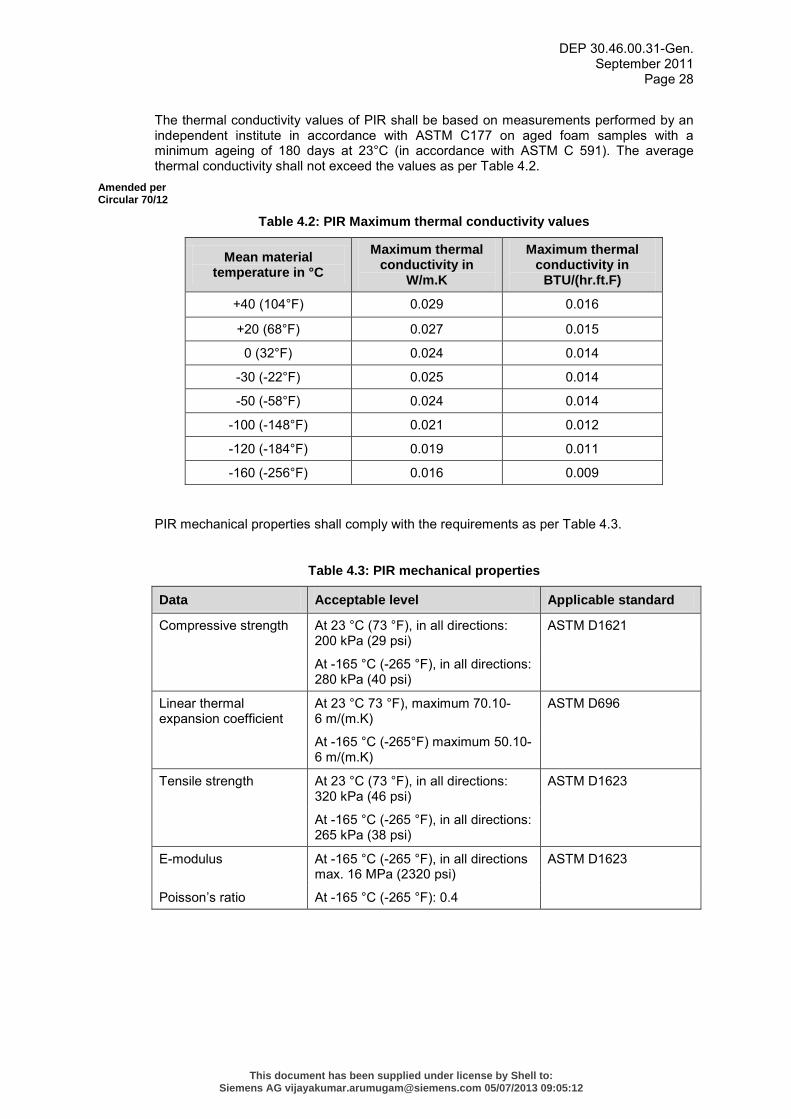
The thermal conductivity values of PIR shall be based on measurements performed by an independent institute in accordance with ASTM C177 on aged foam samples with a minimum ageing of 180 days at 23°C (in accordance with ASTM C 591). The average thermal conductivity shall not exceed the values as per Table 4.2.
Amended per Circular 70/12
Table 4.2: PIR Maximum thermal conductivity values
Mean material temperature in °C
Maximum thermal conductivity in
W/m.K
Maximum thermal conductivity in
BTU/(hr.ft.F)
+40 (104°F) 0.029 0.016
+20 (68°F) 0.027 0.015
0 (32°F) 0.024 0.014
-30 (-22°F) 0.025 0.014
-50 (-58°F) 0.024 0.014
-100 (-148°F) 0.021 0.012
-120 (-184°F) 0.019 0.011
-160 (-256°F) 0.016 0.009
PIR mechanical properties shall comply with the requirements as per Table 4.3.
Table 4.3: PIR mechanical properties
Data Acceptable level Applicable standard
Compressive strength At 23 °C (73 °F), in all directions: 200 kPa (29 psi)
ASTM D1621
At -165 °C (-265 °F), in all directions: 280 kPa (40 psi)
Linear thermal expansion coefficient
At 23 °C 73 °F), maximum 70.10-6 m/(m.K)
ASTM D696
At -165 °C (-265°F) maximum 50.10-6 m/(m.K)
Tensile strength At 23 °C (73 °F), in all directions: 320 kPa (46 psi)
ASTM D1623
At -165 °C (-265 °F), in all directions: 265 kPa (38 psi)
E-modulus At -165 °C (-265 °F), in all directions max. 16 MPa (2320 psi)
ASTM D1623
Poisson’s ratio At -165 °C (-265 °F): 0.4
This document has been supplied under license by Shell to:Siemens AG [email protected] 05/07/2013 09:05:12
DEP 30.46.00.31-Gen. September 2011
Page 29
At service temperature below -50°C (122 °F), the PIR insulation foam shall comply with the following relation:
[σt.(1-δ)] / [Σ.α.∆T] ≥ 1.5
Where:
σt = the average value of 5 test pieces of the tensile strength of the foam at -165°C in kPa as per ASTM D1623.
a) Σ = the average value of 5 pieces of the E-modulus of the foam at -165°C in kPa as per ASTM D 1623.
b) α = the average linear expansion/contraction coefficient of the foam from -165°C up to +23°C in mm/(mm.K) as per ASTM D696.
∆T = Temperature difference between cold surface and ambient temperature (in °K).
c) δ = Poisson’s ratio at -165°C.
The formula above is a cryogenic thermal stress factor, expressing the ration of the tensile strength of the material and the tensile stress induced in the material under cryogenic conditions.
PUR/PIR foam shall be protected against prolonged UV exposure.
4.2.2.2 Cellular Glass
For cellular glass material properties and requirements see (3.2.2.1).
If the temperature difference across the two sides of a single layer of cellular glass is more than 120°C (250°F) or if 120°C (250°F) is bridged by a speed > 2°C /min (3.6 °F/min), cracking may occur as a result of thermal stresses. In the case of such a difference in temperature or temperature gradient, a multi-layer system shall be applied.
The inside segments and section shall be provided with an anti-abrasive paste as specified by the Supplier of the insulation material.
Cellular glass insulation material shall be finished with a weather resistant bitumen based vapour barrier. As an alternative, a factory-applied vapour barrier mastic at segments/section may be applied. The joints shall be sealed with the same material and shall be smoothed over with the pre-applied layer to achieve a monolithical finish.
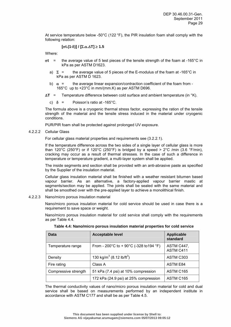
4.2.2.3 Nano/micro porous insulation material
Nano/micro porous insulation material for cold service should be used in case there is a requirement to save space or weight.
Nano/micro porous insulation material for cold service shall comply with the requirements as per Table 4.4.
Table 4.4: Nano/micro porous insulation material properties for cold service
Data Acceptable level Applicable standard
Temperature range From - 200°C to + 90°C (-328 to194 °F) ASTM C447, ASTM C411
Density 130 kg/m3 (8.12 lb/ft3) ASTM C303
Fire rating Class A ASTM E84
Compressive strength 51 kPa (7.4 psi) at 10% compression ASTM C165
172 kPa (24.9 psi) at 25% compression ASTM C165
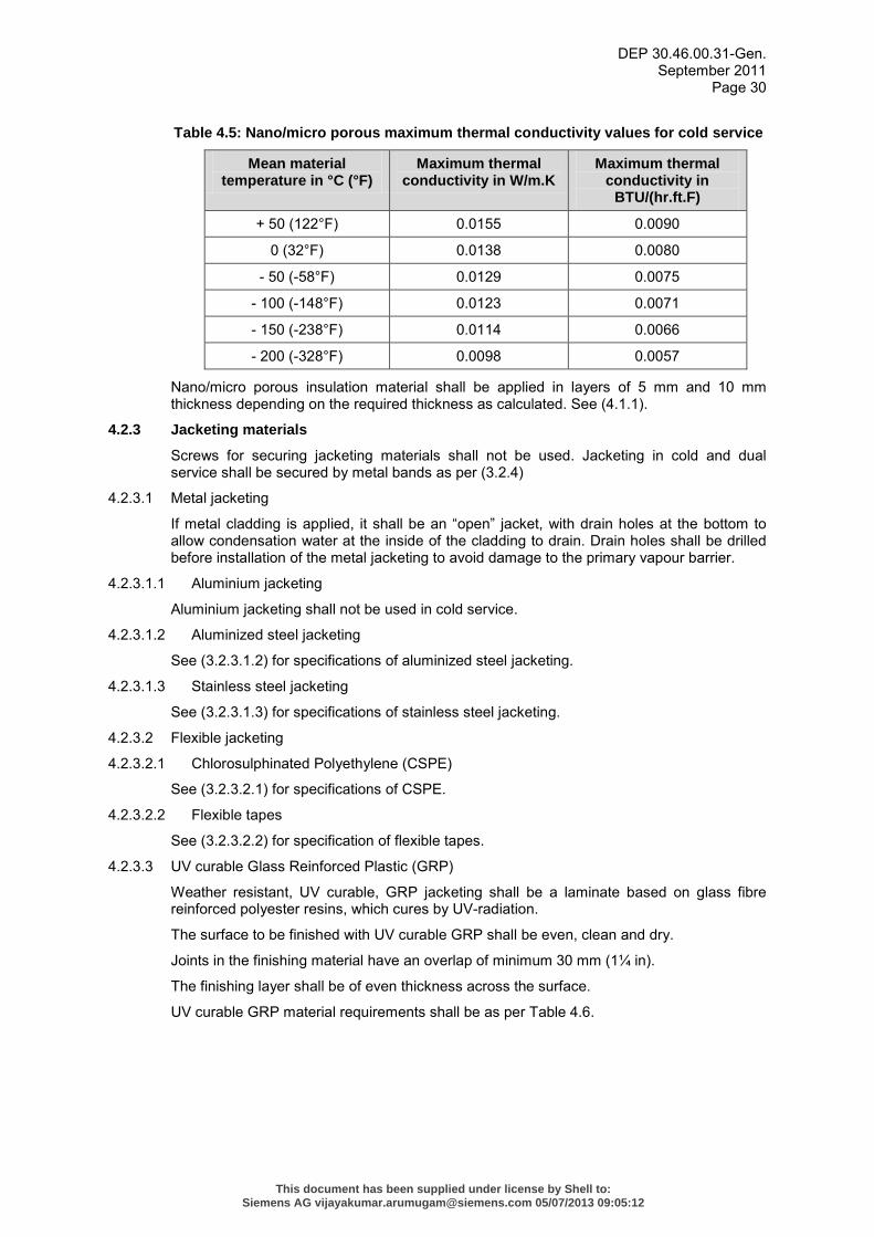
The thermal conductivity values of nano/micro porous insulation material for cold and dual service shall be based on measurements performed by an independent institute in accordance with ASTM C177 and shall be as per Table 4.5.
This document has been supplied under license by Shell to:Siemens AG [email protected] 05/07/2013 09:05:12
DEP 30.46.00.31-Gen. September 2011
Page 30
Table 4.5: Nano/micro porous maximum thermal conductivity values for cold service
Mean material temperature in °C (°F)
Maximum thermal conductivity in W/m.K
Maximum thermal conductivity in
BTU/(hr.ft.F)
+ 50 (122°F) 0.0155 0.0090
0 (32°F) 0.0138 0.0080
- 50 (-58°F) 0.0129 0.0075
- 100 (-148°F) 0.0123 0.0071
- 150 (-238°F) 0.0114 0.0066
- 200 (-328°F) 0.0098 0.0057
Nano/micro porous insulation material shall be applied in layers of 5 mm and 10 mm thickness depending on the required thickness as calculated. See (4.1.1).
4.2.3 Jacketing materials
Screws for securing jacketing materials shall not be used. Jacketing in cold and dual service shall be secured by metal bands as per (3.2.4)
4.2.3.1 Metal jacketing
If metal cladding is applied, it shall be an “open” jacket, with drain holes at the bottom to allow condensation water at the inside of the cladding to drain. Drain holes shall be drilled before installation of the metal jacketing to avoid damage to the primary vapour barrier.
4.2.3.1.1 Aluminium jacketing
Aluminium jacketing shall not be used in cold service.
4.2.3.1.2 Aluminized steel jacketing
See (3.2.3.1.2) for specifications of aluminized steel jacketing.
4.2.3.1.3 Stainless steel jacketing
See (3.2.3.1.3) for specifications of stainless steel jacketing.
4.2.3.2 Flexible jacketing
4.2.3.2.1 Chlorosulphinated Polyethylene (CSPE)
See (3.2.3.2.1) for specifications of CSPE.
4.2.3.2.2 Flexible tapes
See (3.2.3.2.2) for specification of flexible tapes.
4.2.3.3 UV curable Glass Reinforced Plastic (GRP)
Weather resistant, UV curable, GRP jacketing shall be a laminate based on glass fibre reinforced polyester resins, which cures by UV-radiation.
The surface to be finished with UV curable GRP shall be even, clean and dry.
Joints in the finishing material have an overlap of minimum 30 mm (1¼ in).
The finishing layer shall be of even thickness across the surface.
UV curable GRP material requirements shall be as per Table 4.6.
This document has been supplied under license by Shell to:Siemens AG [email protected] 05/07/2013 09:05:12
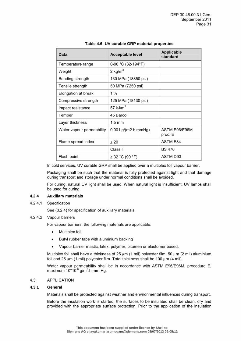
DEP 30.46.00.31-Gen. September 2011
Page 31
Table 4.6: UV curable GRP material properties
Data Acceptable level Applicable standard
Temperature range 0-90 °C (32-194°F)
Weight 2 kg/m2
Bending strength 130 MPa (18850 psi)
Tensile strength 50 MPa (7250 psi)
Elongation at break 1 %
Compressive strength 125 MPa (18130 psi)
Impact resistance 57 kJ/m2
Temper 45 Barcol
Layer thickness 1.5 mm
Water vapour permeability 0.001 g/(m2.h.mmHg) ASTM E96/E96M proc. E
Flame spread index ≤ 20 ASTM E84
Class I BS 476
Flash point ≥ 32 °C (90 °F) ASTM D93
In cold services, UV curable GRP shall be applied over a multiplex foil vapour barrier.
Packaging shall be such that the material is fully protected against light and that damage during transport and storage under normal conditions shall be avoided.
For curing, natural UV light shall be used. When natural light is insufficient, UV lamps shall be used for curing.
4.2.4 Auxiliary materials
4.2.4.1 Specification
See (3.2.4) for specification of auxiliary materials.
4.2.4.2 Vapour barriers
For vapour barriers, the following materials are applicable:
• Multiplex foil
• Butyl rubber tape with aluminium backing
• Vapour barrier mastic, latex, polymer, bitumen or elastomer based.
Multiplex foil shall have a thickness of 25 µm (1 mil) polyester film, 50 µm (2 mil) aluminium foil and 25 µm (1 mil) polyester film. Total thickness shall be 100 µm (4 mil).
Water vapour permeability shall be in accordance with ASTM E96/E96M, procedure E, maximum 10*10-6 g/m2.h.mm.Hg.
4.3 APPLICATION
4.3.1 General
Materials shall be protected against weather and environmental influences during transport.
Before the insulation work is started, the surfaces to be insulated shall be clean, dry and provided with the appropriate surface protection. Prior to the application of the insulation
This document has been supplied under license by Shell to:Siemens AG [email protected] 05/07/2013 09:05:12
DEP 30.46.00.31-Gen. September 2011
Page 32
material the Contractor shall obtain a “released for insulation” document stating the surface is clean, dry and prepared as required.
Provisions shall be made to ensure that the materials can also be fitted under poor weather conditions. Prior to application of the finishing material the insulation material shall be dry.
When the insulation is applied in two layers, the sections and segments shall be staggered both radial and axial. An overlap of at least 150 mm (6 in) shall be observed for the joints.
Insulation activities including the jacketing shall be completed in one day. Exposed insulation material is properly covered for water and moisture ingress.
Nameplates, reference- and measuring points shall remain visible at all times. Discharge and air relief valves shall remain operable.
Edges of the recesses shall have a weatherproof finish.
Insulation through walls, partitions and floors shall be uninterrupted and of uniform thickness.
A minimum space of 25 mm (1 in) shall be observed between the insulation finishing and the adjacent surfaces.
The jacketing shall be without counter-swages and be constructed in such a way that any condensation moisture can drain from the cladding.
Metal jacketing shall be fastened with stainless steel bands with a minimum cross-section of 13x0.5 mm (½ x 0.02 in).
Horizontal joints shall be installed so that rainwater cannot enter the insulation system.
Longitudinal joints shall be installed opposite the prevailing wind direction. At the joints, the jacketing shall have an overlap of at least 50 mm (2 in). The longitudinal seams shall be staggered.
The flange and fitting insulation shall be fitted over the connected pipe insulation over a distance that is at least equal to the thickness of the pipe insulation, with a minimum of 50 mm (2 in).
Insulation details for cold insulation shall be as per CINI 5.0.00.
Insulation details for cryogenic insulation shall be as per CINI 10.5.1 to 10.5.13.
Flexible CSPE and flexible tape jacketing application shall be as per (Appendix H).
4.3.2 Surface preparation
Ingress of rainwater and corrosive products or condensation of water vapour in the insulation can cause severe CUI and ESCC, and increases the thermal conductivity (reducing insulation values) significantly. To protect the steel from CUI and ESCC, a surface protection system shall be applied in accordance with DEP 30.48.00.31-Gen. and DEP 30.48.40.31-Gen.
Before the insulation work is started, the surfaces to be insulated shall be clean, dry and provided with the appropriate surface protection. Prior to the application of the insulation material the Contractor shall obtain a “released for insulation” document stating the surface is clean, dry and prepared as required.
4.3.3 Pipe supports in cold insulation systems
The insulation thickness at the supports shall be the same as the piping insulation.
The material of the insulation sections at the supports shall match with the adjacent insulation system. In doing so, a similar material with a higher compressive strength may be applied.
The dimensions of the pipe supports shall be calculated in detail. Governing factors shall be as follows:
a) The maximum design load of the support, based on two span lengths.
This document has been supplied under license by Shell to:Siemens AG [email protected] 05/07/2013 09:05:12
DEP 30.46.00.31-Gen. September 2011
Page 33
b) Compressive strength of the insulation material.
c) Safety factor 5:1 for the compressive strength at minimum operating temperatures.
d) Load transfer based on 60° load spread.
e) Load spread underneath the brackets / steel support cradles during fixing of the bolt.
f) Clamping forces on the pipeline, such that the support moves with the pipe. NOTE: The support shall not move across the insulation system (cladding) and the pipe shall not move inside
the insulation system.
g) Length of the base plates of the support based on maximum contraction/expansion of the pipeline.
The HD PIR/PUR foam at the bottom part of the support shall have a minimum density of:
• 160 kg/m3 (10 lbm/ft3) for pipe diameters up to 200 mm (8 in)
• 224 kg/m3 (14 lbm/ft3) for pipe diameters between 200 mm (8 in) and 600 mm (24 in)
• 320 kg/m3 (20 lbm/ft3) for pipe diameters above 600 mm (24 in)
The top part of the support shall have a minimum density of 160 kg/m3 (10 lb/ft3).
Pipe support design and application in cold insulation systems shall be submitted to the Principal for review and comments.
For pipe supports in cold service, reference is made to CINI 5.1.09, 5.1.10 and 5.1.11.
For pipe supports in cryogenic service, reference is made to CINI 10.5.01 and 10.5.02.
4.3.4 Shop application of sprayed or poured PUR/PIR for pre-insulated pipe work and in-situ moulded PUR/PIR.
Shop applied sprayed or poured PUR/PIR for pre-insulated pipe work shall have the same material properties as preformed PUR/PIR sections. Reference is made to EN 13941 and EN 253.
In-situ moulded and dispensed PUR/PIR insulation shall have the same material properties as preformed PUR/PIR sections.
4.3.5 Expansion and contraction joints
Thermal stress calculations shall be provided as the basis for required expansion and/or contraction joints.
Expansion and/or contraction joints and their positions shall be designed based on the expected differential contraction between piping/equipment and insulation material as a result of extreme temperatures.
Each contraction joint shall be filled up with a resilient insulating material for compression and/or extension.
In the case of vertical piping and equipment with support rings, a contraction joint shall be provided under each support ring.
Reference is made to DEP standard drawing S.40.001 and S.40.002 for alternatives to CINI 5.2.06.
This document has been supplied under license by Shell to:Siemens AG [email protected] 05/07/2013 09:05:12
DEP 30.46.00.31-Gen. September 2011
Page 34
5. QUALITY ASSURANCE & QUALITY CONTROL
5.1 QUALITY PLAN
For application of insulation systems, a Quality Plan based on ISO 9001 shall be provided.
The Quality plan shall include:
a) The delegated responsibilities of the several sections of the works and all procedures, method statements and inspection and test plan (ITP).
b) The method statements shall describe the execution plan, materials, trade and quality procedures.
c) In the ITP, all the test procedures shall be described, such as the number of samples, hold/witness points, test frequencies, acceptance/rejection criteria etc. of all the applicable insulation systems.
d) Inspections shall be carried out prior, during and after completion of any stage of the work, beginning with materials checks and ending with final performance checks.
e) The Quality Plan shall clearly indicate how and in which stages material test reports shall be available and how it is documented.
f) The following stages shall be indicated:
a. the time the materials arrive in storage on site
b. before the materials are processed or applied
c. during application
d. before and during the installation of the jacketing.
5.2 QUALITY CONTROL
5.2.1 Inspection of materials
All materials shall comply with the minimum requirements as stated in this DEP.
All materials and application methods shall be suitable for the local weather conditions.
The materials shall be inspected at the Supplier's workshop and at arrival on site.
Prior to commencement of the work, data sheets, the safety data sheets and method statements of the various materials shall be submitted, together with the laboratory test certificates from independent test laboratories.
5.2.2 Inspection prior to execution
Before insulation application, a pre-insulation survey and measurement of the system to verify the design shall be performed.
Application of insulation is only allowed after submission of a release for insulation document. The release for insulation document shall include:
• Equipment and pipelines, complete with supports, are ready and pressure tested.
• Flange connections are accepted.
• The corrosion protection systems has been applied and accepted.
• The surface to be insulated is clean and dry, free of grease, salt deposits, oil and dirt.
5.2.3 Inspection during execution
Inspections shall be carried out on materials and applications during all execution of the works to ensure compliance with the specifications and procedures, as laid down in the Quality Plan. Beforehand, the steps shall be established in which the insulation system shall be applied and which phase may be started after hold/witness point.
This document has been supplied under license by Shell to:Siemens AG [email protected] 05/07/2013 09:05:12

DEP 30.46.00.31-Gen. September 2011
Page 35
5.2.4 Final inspection and release
After completion of the insulation system or sections thereof, a final inspection shall be conducted. The application shall be inspected to determine that the insulation is of proper thickness and that its materials, workmanship and finishes meet the specifications. The insulation Contractor shall remain responsible for the performance of insulation systems until the warranty period has expired. Damages shall be repaired.
After start-up, the thermal performance of the hot insulation systems shall be verified by measuring the surface temperature or by infrared surveys. Cold insulation systems shall be subjected to thermographic surveys between 3-6 months after initial start-up to identify deficiencies. These deficiencies shall be marked and shall be made good at the earliest opportunity.
Furthermore reference is made to CINI 1.3.05 and 10.2.01
This document has been supplied under license by Shell to:Siemens AG [email protected] 05/07/2013 09:05:12
DEP 30.46.00.31-Gen. September 2011
Page 36
6. REFERENCES
In this DEP, reference is made to the following publications: NOTES: 1. Unless specifically designated by date, the latest edition of each publication shall be used,
together with any amendments/supplements/revisions thereto.
2. The DEPs and most referenced external standards are available to Shell staff on the SWW (Shell Wide Web) at http://sww.shell.com/standards/.
SHELL STANDARDS
Protective coatings for onshore facilities DEP 30.48.00.31-Gen.
Thermal spray coatings of aluminium and 85/15 zinc/aluminium alloy
DEP 30.48.40.31-Gen.
Piping – General Requirements DEP 31.38.01.11-Gen.
Protective steam heating of piping systems DEP 31.38.30.11-Gen.
Acoustic insulation for piping (amendments/supplements to ISO 15665)
DEP 31.46.00.31-Gen.
Electrical trace heating DEP 33.68.30.32-Gen.
Full containment refrigerated LNG tanks DEP 34.51.01.32-Gen.
Protective coatings for offshore facilities DEP 70.48.11.30-Gen.
SHELL STANDARD DRAWINGS
Typical details of insulation collar for carbon, low-alloy steel and stainless steel apparatus
S 10.056
Vacuum support ring contraction joint – alternative for CINI 5.2.06 with high density PIR support ring
S.40.001
Vacuum support ring contraction joint – alternative for CINI 5.2.06 in non metallic jacketing
S.40.002
AMERICAN STANDARDS
Process Piping - Includes Interpretation 22 ASME B31.3
Standard Specification for Stainless and Heat-Resisting Chromium-Nickel Steel Plate, Sheet, and Strip
ASTM A167
Standard Specification for Steel Sheet, Aluminum-Coated, by the Hot-Dip Process
ASTM A463/A463M
Standard Specification for Aluminum and Aluminum-Alloy Sheet and Plate [Metric]
ASTM B209M
Standard Test Method for Measuring Compressive Properties of Thermal Insulations
ASTM C165
Standard Test Method for Steady-State Heat Flux Measurements and Thermal Transmission Properties by Means of the Guarded-Hot-Plate Apparatus
ASTM C177
Standard Test Method for Density and Dimensions of Preformed Pipe-Covering-Type Thermal Insulation
ASTM C302
Standard Test Method for Dimensions and Density of Preformed Block and Board–Type Thermal Insulation
ASTM C303
Standard Test Method for Hot Service Performance of High Temperature Thermal Insulation
ASTM C411
This document has been supplied under license by Shell to:Siemens AG [email protected] 05/07/2013 09:05:12
DEP 30.46.00.31-Gen. September 2011
Page 37
Standard Practice for Estimating the Maximum Use of Temperature of Thermal Insulations
ASTM C447
Standard Specification for Mineral Fibre Pipe Insulation ASTM C547
Standard Specification for Unfaced Preformed Rigid Cellular Polyisocyanurate Thermal Insulation
ASTM C591
Standard Practice for Estimate of the Heat Gain or Loss and the Surface Temperatures of Insulated Flat, Cylindrical, and Spherical Systems by Use of Computer Programs
ASTM C680
Standard Test Methods for Chemical Analysis of Thermal Insulation Materials for Leachable Chloride, Fluoride, Silicate, and Sodium Ions
ASTM C871
Standard Test Methods for Flash Point by Pensky-Mertens Closed Cup Tester
ASTM D93 Rev A
Standard Test Method for Coefficient of Linear Thermal Expansion of Plastics Between −30 Degrees ºC and 30 Degrees ºC with a Vitreous Silica Dilatometer
ASTM D696
Standard Test Method for Tensile Properties of Thin Plastic Sheeting
ASTM D882
Standard Test Methods for Pressure-Sensitive Adhesive-Coated Tapes Used for Electrical and Electronic Applications
ASTM D1000
Standard Test Method for Compressive Properties of Rigid Cellular Plastics
ASTM D1621
Standard Test Method for Apparent Density of Rigid Cellular Plastics
ASTM D1622
Standard Test Method for Tensile and Tensile Adhesion Properties of Rigid Cellular Plastics
ASTM D1623
Standard Test Method for Water Absorption of Rigid Cellular Plastics
ASTM D2842
Standard Test Method for Hydrostatic Pressure Resistance of Waterproofing Membranes
ASTM D5385
Standard Test Method for Open Cell Content of Rigid Cellular Plastics
ASTM D6226
Standard Test Method for Surface Burning Characteristics of Building Materials
ASTM E84 REV A
Standard Test Method for Water Vapour Transmission of Materials ASTM E96/E96M
BRITISH STANDARDS
Fire Test on Building Materials and Structures BS 476
Part 7: Method of Test to Determine the Classification of the Surface Spread of Flame of Products
BS 476-7
DUTCH STANDARDS
Committee Insulation Netherlands Industry (CINI) – Manual Insulation for Industries
CINI Manual latest version
This document has been supplied under license by Shell to:Siemens AG [email protected] 05/07/2013 09:05:12
DEP 30.46.00.31-Gen. September 2011
Page 38
EUROPEAN STANDARDS
District Heating Pipes — Preinsulated Bonded Pipe Systems for Directly Buried Hot Water Networks — Pipe Assembly of Steel Service Pipe, Polyurethane Thermal Insulation and Outer Casing of Polyethylene
EN 253
Thermal Insulating Products for Building Applications - Determination of Water Vapour Transmission Properties
EN 12086
Design and Installation of Preinsulated Bonded Pipe Systems for District Heating
EN 13941
GERMAN STANDARDS
Arbeitsgemeinschaft Industriebau e.V. - Bestimmung hydrophober Eigenschaften von Mineralfaserdämmstoffen
AGI Q136
Thermal insulation for heated and refrigerated industrial and domestic installations - Calculations, guarantees, measuring and testing methods, quality assurance, supply conditions
VDI 2055
INTERNATIONAL STANDARDS
International Maritime Organization Resolution – Recommendation on improved fire test procedures for surface flammability of bulkhead, ceiling and deck finish materials
IMO resolution A.653 (16)
Rubber, Vulcanized or Thermoplastic – Determination of Tensile Stress-Strain Properties
ISO 37
Reaction to fire tests for products — Non-combustibility test ISO 1182
Slotted Pan Head Tapping Screws ISO 1481
Quality Management Systems - Requirements ISO 9001
Thermal Insulation for Building Equipment and Industrial Installations — Calculation Rules
ISO 12241
Acoustics – Acoustic Insulation For Pipes, Valves and Flanges ISO 15665
Paints and varnishes - Performance requirements for protective paint systems for offshore and related structures
ISO 20340
This document has been supplied under license by Shell to:Siemens AG [email protected] 05/07/2013 09:05:12
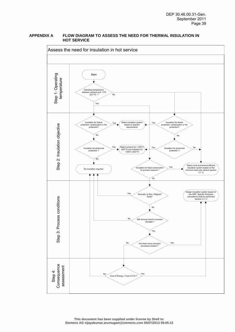
DEP 30.46.00.31-Gen. September 2011
Page 39
APPENDIX A FLOW DIAGRAM TO ASSESS THE NEED FOR THERMAL INSULATION IN HOT SERVICE
Assess the need for insulation in hot serviceS
tep
4:
Con
sequ
ence
as
sess
men
tS
tep
2: In
sula
tion
obje
ctiv
eS
tep
3: P
roce
ss c
ondi
tions
Ste
p 1:
Ope
ratin
g te
mpe
ratu
re
Start
Operating temperature between ambient and +175
(347°F) ? No
Yes
Insulation for personnel protection ?
Yes
No
Insulation for freeze protection, winterization or fire
protection?
No
No insulation required. Insulation for heat conservation for process reasons ?
Select most economical efficient insulation system based on the
minimum total cost method (section 3.1.1)
No
Normally no flow. Stagnant fluids?
Will removal result in process changes ?
Are there more corrosive processes present ?
Yes Yes
Yes
No
Yes
No
Cost of Energy > Cost of CUI ?
No Yes
No
Design insulation system based on this DEP. Specific thickness
calculations shall be performed (section 3.1.1)
Yes
Select insulation system based on specific
requirements
Insulation for personnel protection ?
No
Yes
Select screens for < 250°C (482°F) and insulation for
>250°C (482°F)
Insulation for freeze protection, winterization or fire
protection?
Yes
No
This document has been supplied under license by Shell to:Siemens AG [email protected] 05/07/2013 09:05:12
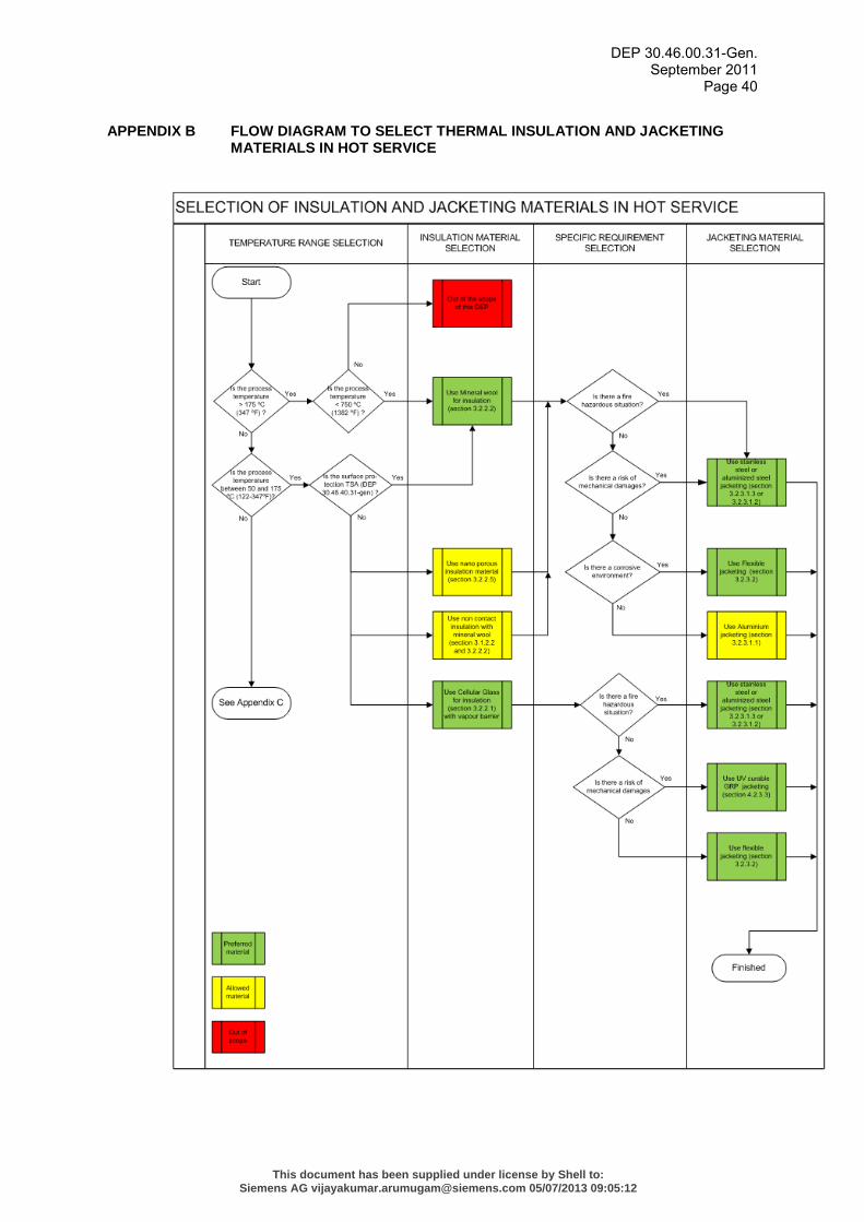
DEP 30.46.00.31-Gen. September 2011
Page 40
APPENDIX B FLOW DIAGRAM TO SELECT THERMAL INSULATION AND JACKETING MATERIALS IN HOT SERVICE
This document has been supplied under license by Shell to:Siemens AG [email protected] 05/07/2013 09:05:12
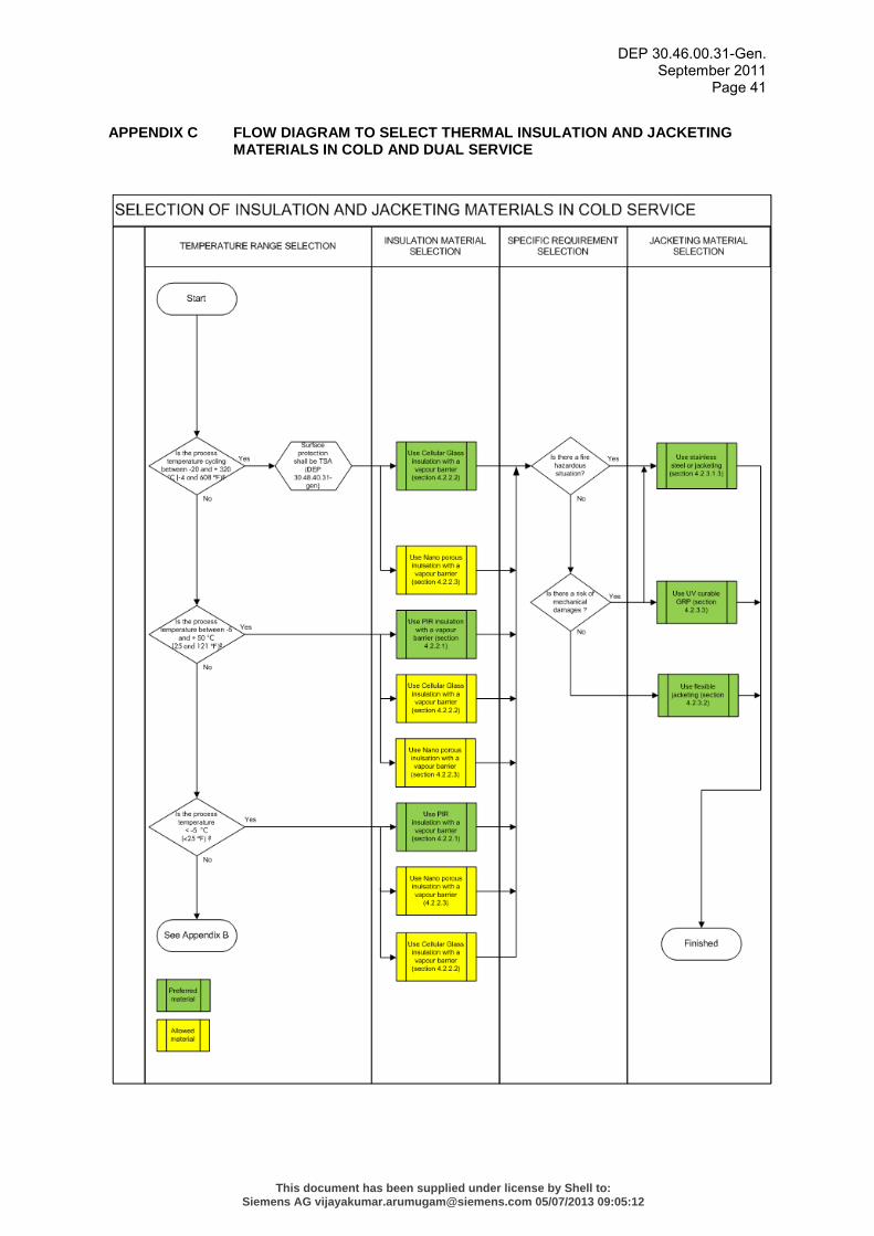
DEP 30.46.00.31-Gen. September 2011
Page 41
APPENDIX C FLOW DIAGRAM TO SELECT THERMAL INSULATION AND JACKETING MATERIALS IN COLD AND DUAL SERVICE
This document has been supplied under license by Shell to:Siemens AG [email protected] 05/07/2013 09:05:12
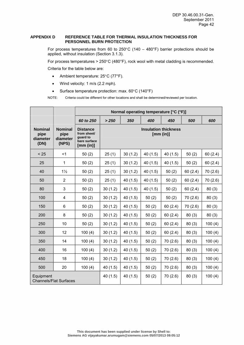
DEP 30.46.00.31-Gen. September 2011
Page 42
APPENDIX D REFERENCE TABLE FOR THERMAL INSULATION THICKNESS FOR PERSONNEL BURN PROTECTION
For process temperatures from 60 to 250°C (140 – 480°F) barrier protections should be applied, without insulation (Section 3.1.3).
For process temperatures > 250°C (480°F), rock wool with metal cladding is recommended.
Criteria for the table below are:
• Ambient temperature: 25°C (77°F).
• Wind velocity: 1 m/s (2.2 mph).
• Surface temperature protection: max. 60°C (140°F) NOTE: Criteria could be different for other locations and shall be determined/reviewed per location.
Normal operating temperature [°C (°F)]
60 to 250 > 250 350 400 450 500 600
Nominal pipe
diameter (DN)
Nominal pipe
diameter (NPS)
Distance from sheet/ guard to bare surface [mm (in)]
Insulation thickness [mm (in)]
< 25 <1 50 (2) 25 (1) 30 (1.2) 40 (1.5) 40 (1.5) 50 (2) 60 (2.4)
25 1 50 (2) 25 (1) 30 (1.2) 40 (1.5) 40 (1.5) 50 (2) 60 (2.4)
40 1½ 50 (2) 25 (1) 30 (1.2) 40 (1.5) 50 (2) 60 (2.4) 70 (2.6)
50 2 50 (2) 25 (1) 40 (1.5) 40 (1.5) 50 (2) 60 (2.4) 70 (2.6)
80 3 50 (2) 30 (1.2) 40 (1.5) 40 (1.5) 50 (2) 60 (2.4) 80 (3)
100 4 50 (2) 30 (1.2) 40 (1.5) 50 (2) 50 (2) 70 (2.6) 80 (3)
150 6 50 (2) 30 (1.2) 40 (1.5) 50 (2) 60 (2.4) 70 (2.6) 80 (3)
200 8 50 (2) 30 (1.2) 40 (1.5) 50 (2) 60 (2.4) 80 (3) 80 (3)
250 10 50 (2) 30 (1.2) 40 (1.5) 50 (2) 60 (2.4) 80 (3) 100 (4)
300 12 100 (4) 30 (1.2) 40 (1.5) 50 (2) 60 (2.4) 80 (3) 100 (4)
350 14 100 (4) 30 (1.2) 40 (1.5) 50 (2) 70 (2.6) 80 (3) 100 (4)
400 16 100 (4) 30 (1.2) 40 (1.5) 50 (2) 70 (2.6) 80 (3) 100 (4)
450 18 100 (4) 30 (1.2) 40 (1.5) 50 (2) 70 (2.6) 80 (3) 100 (4)
500 20 100 (4) 40 (1.5) 40 (1.5) 50 (2) 70 (2.6) 80 (3) 100 (4)
Equipment Channels/Flat Surfaces
40 (1.5) 40 (1.5) 50 (2) 70 (2.6) 80 (3) 100 (4)
This document has been supplied under license by Shell to:Siemens AG [email protected] 05/07/2013 09:05:12
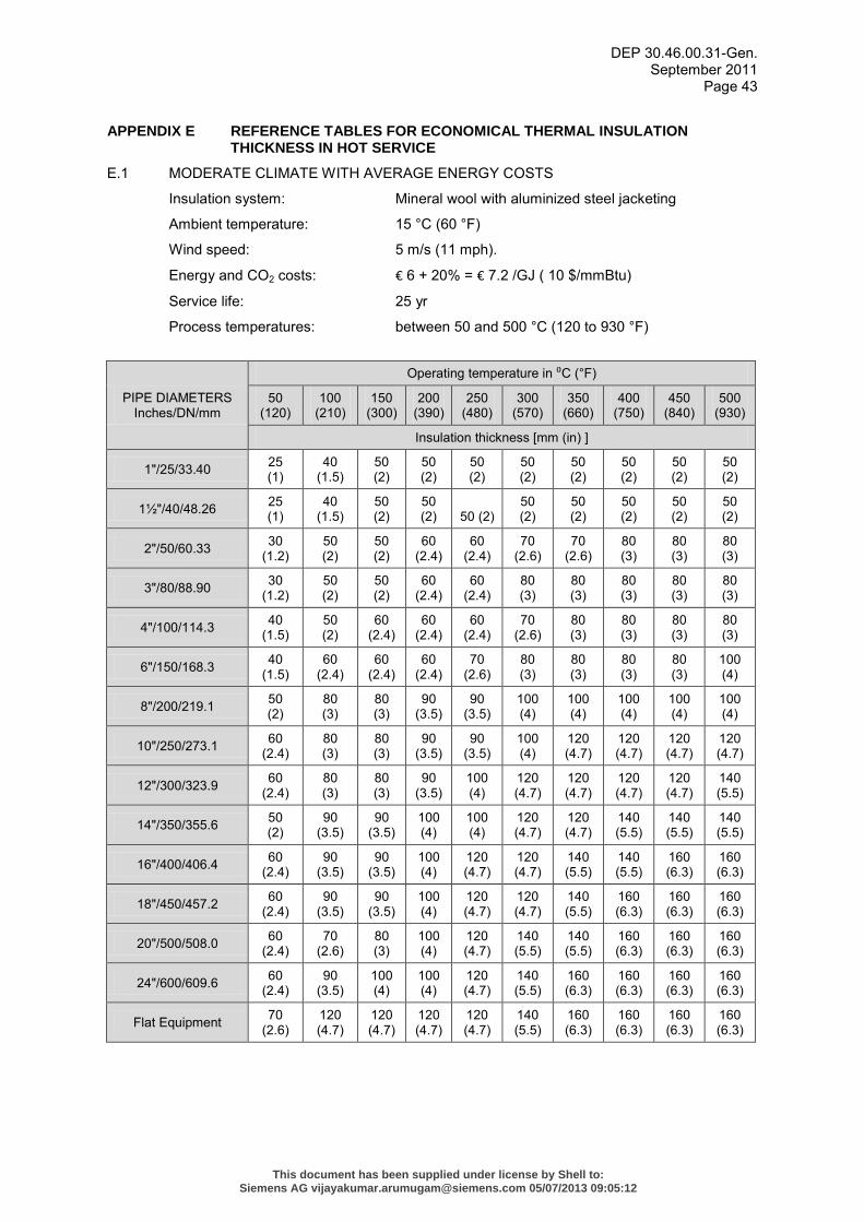
DEP 30.46.00.31-Gen. September 2011
Page 43
APPENDIX E REFERENCE TABLES FOR ECONOMICAL THERMAL INSULATION THICKNESS IN HOT SERVICE
E.1 MODERATE CLIMATE WITH AVERAGE ENERGY COSTS
Insulation system: Mineral wool with aluminized steel jacketing
Ambient temperature: 15 °C (60 °F)
Wind speed: 5 m/s (11 mph).
Energy and CO2 costs: € 6 + 20% = € 7.2 /GJ ( 10 $/mmBtu)
Service life: 25 yr
Process temperatures: between 50 and 500 °C (120 to 930 °F)
PIPE DIAMETERS Inches/DN/mm
Operating temperature in ⁰C (°F)
50 (120)
100 (210)
150 (300)
200 (390)
250 (480)
300 (570)
350 (660)
400 (750)
450 (840)
500 (930)
Insulation thickness [mm (in) ]
1"/25/33.40 25 (1)
40 (1.5)
50 (2)
50 (2)
50 (2)
50 (2)
50 (2)
50 (2)
50 (2)
50 (2)
1½"/40/48.26 25 (1)
40 (1.5)
50 (2)
50 (2) 50 (2)
50 (2)
50 (2)
50 (2)
50 (2)
50 (2)
2"/50/60.33 30 (1.2)
50 (2)
50 (2)
60 (2.4)
60 (2.4)
70 (2.6)
70 (2.6)
80 (3)
80 (3)
80 (3)
3"/80/88.90 30 (1.2)
50 (2)
50 (2)
60 (2.4)
60 (2.4)
80 (3)
80 (3)
80 (3)
80 (3)
80 (3)
4"/100/114.3 40 (1.5)
50 (2)
60 (2.4)
60 (2.4)
60 (2.4)
70 (2.6)
80 (3)
80 (3)
80 (3)
80 (3)
6"/150/168.3 40 (1.5)
60 (2.4)
60 (2.4)
60 (2.4)
70 (2.6)
80 (3)
80 (3)
80 (3)
80 (3)
100 (4)
8"/200/219.1 50 (2)
80 (3)
80 (3)
90 (3.5)
90 (3.5)
100 (4)
100 (4)
100 (4)
100 (4)
100 (4)
10"/250/273.1 60 (2.4)
80 (3)
80 (3)
90 (3.5)
90 (3.5)
100 (4)
120 (4.7)
120 (4.7)
120 (4.7)
120 (4.7)
12"/300/323.9 60 (2.4)
80 (3)
80 (3)
90 (3.5)
100 (4)
120 (4.7)
120 (4.7)
120 (4.7)
120 (4.7)
140 (5.5)
14"/350/355.6 50 (2)
90 (3.5)
90 (3.5)
100 (4)
100 (4)
120 (4.7)
120 (4.7)
140 (5.5)
140 (5.5)
140 (5.5)
16"/400/406.4 60 (2.4)
90 (3.5)
90 (3.5)
100 (4)
120 (4.7)
120 (4.7)
140 (5.5)
140 (5.5)
160 (6.3)
160 (6.3)
18"/450/457.2 60 (2.4)
90 (3.5)
90 (3.5)
100 (4)
120 (4.7)
120 (4.7)
140 (5.5)
160 (6.3)
160 (6.3)
160 (6.3)
20"/500/508.0 60 (2.4)
70 (2.6)
80 (3)
100 (4)
120 (4.7)
140 (5.5)
140 (5.5)
160 (6.3)
160 (6.3)
160 (6.3)
24"/600/609.6 60 (2.4)
90 (3.5)
100 (4)
100 (4)
120 (4.7)
140 (5.5)
160 (6.3)
160 (6.3)
160 (6.3)
160 (6.3)
Flat Equipment 70 (2.6)
120 (4.7)
120 (4.7)
120 (4.7)
120 (4.7)
140 (5.5)
160 (6.3)
160 (6.3)
160 (6.3)
160 (6.3)
This document has been supplied under license by Shell to:Siemens AG [email protected] 05/07/2013 09:05:12
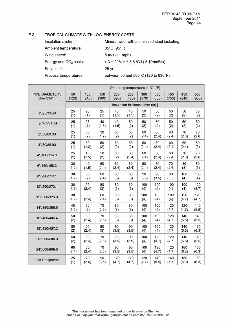
DEP 30.46.00.31-Gen. September 2011
Page 44
E.2 TROPICAL CLIMATE WITH LOW ENERGY COSTS
Insulation system: Mineral wool with aluminized steel jacketing
Ambient temperature: 35°C (95°F)
Wind speed: 5 m/s (11 mph).
Energy and CO2 costs: € 3 + 20% = € 3.6 /GJ ( 5 $/mmBtu)
Service life: 25 yr
Process temperatures: between 50 and 500°C (120 to 930°F)
PIPE DIAMETERS Inches/DN/mm
Operating temperature in ⁰C (°F)
50 (120)
100 (210)
150 (300)
200 (390)
250 (480)
300 (570)
350 (660)
400 (750)
450 (840)
500 (930)
Insulation thickness [mm (in) ]
1"/25/33.40 25 (1)
25 (1)
25 (1)
40 (1.5)
40 (1.5)
50 (2)
50 (2)
50 (2)
50 (2)
50 (2)
1½"/40/48.26 25 (1)
25 (1)
40 (1.5)
40 (1.5)
50 (2)
50 (2)
50 (2)
50 (2)
50 (2)
50 (2)
2"/50/60.33 25 (1)
50 (2)
30 (1.2)
50 (2)
50 (2)
60 (2.4)
60 (2.4)
60 (2.4)
70 (2.6)
70 (2.6)
3"/80/88.90 25 (1)
30 (1.2)
50 (2)
50 (2)
50 (2)
60 (2.4)
60 (2.4)
60 (2.4)
60 (2.4)
80 (3)
4"/100/114.3 25 (1)
40 (1.5)
50 (2)
50 (2)
60 (2.4)
60 (2.4)
60 (2.4)
60 (2.4)
70 (2.6)
70 (2.6)
6"/150/168.3 30 (1.2)
40 (1.5)
60 (2.4)
60 (2.4)
60 (2.4)
60 (2.4)
60 (2.4)
70 (2.6)
80 (3)
80 (3)
8"/200/219.1 30 (1.2)
50 (2)
60 (2.4)
80 (3)
80 (3)
90 (3.5)
90 (3.5)
90 (3.5)
100 (4)
100 (4)
10"/250/273.1 30 (1.2)
60 (2.4)
80 (3)
80 (3)
80 (3)
100 (4)
100 (4)
100 (4)
100 (4)
120 (4.7)
12"/300/323.9 30 (1.2)
60 (2.4)
60 (2.4)
80 (3)
80 (3)
100 (4)
100 (4)
100 (4)
120 (4.7)
120 (4.7)
14"/350/355.6 40 (1.5)
50 (2)
70 (2.6)
80 (3)
80 (3)
100 (4)
100 (4)
120 (4.7)
120 (4.7)
140 (5.5)
16"/400/406.4 50 (2)
60 (2.4)
70 (2.6)
80 (3)
80 (3)
100 (4)
100 (4)
120 (4.7)
140 (5.5)
140 (5.5)
18"/450/457.2 50 (2)
60 (2.4)
80 (3)
90 (3.5)
90 (3.5)
100 (4)
100 (4)
120 (4.7)
140 (5.5)
160 (6.3)
20"/500/508.0 50 (2)
60 (2.4)
70 (2.6)
90 (3.5)
90 (3.5)
100 (4)
120 (4.7)
120 (4.7)
140 (5.5)
140 (5.5)
24"/600/609.6 60 (2.4)
60 (2.4)
70 (2.6)
90 (3.5)
90 (3.5)
100 (4)
120 (4.7)
120 (4.7)
160 (6.3)
160 (6.3)
Flat Equipment 25 (1)
70 (2.6)
90 (3.5)
120 (4.7)
120 (4.7)
120 (4.7)
140 (5.5)
140 (5.5)
160 (6.3)
160 (6.3)
This document has been supplied under license by Shell to:Siemens AG [email protected] 05/07/2013 09:05:12
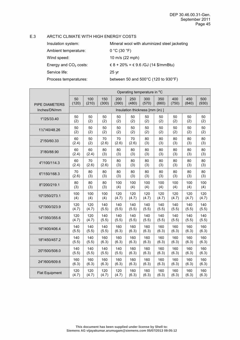
DEP 30.46.00.31-Gen. September 2011
Page 45
E.3 ARCTIC CLIMATE WITH HIGH ENERGY COSTS
Insulation system: Mineral wool with aluminized steel jacketing
Ambient temperature: 0 °C (30 °F)
Wind speed: 10 m/s (22 mph)
Energy and CO2 costs: € 8 + 20% = € 9.6 /GJ (14 $/mmBtu)
Service life: 25 yr
Process temperatures: between 50 and 500°C (120 to 930°F)
PIPE DIAMETERS Inches/DN/mm
Operating temperature in ⁰C
50 (120)
100 (210)
150 (300)
200 (390)
250 (480)
300 (570)
350 (660)
400 (750)
450 (840)
500 (930)
Insulation thickness [mm (in) ]
1"/25/33.40 50 (2)
50 (2)
50 (2)
50 (2)
50 (2)
50 (2)
50 (2)
50 (2)
50 (2)
50 (2)
1½"/40/48.26 50 (2)
50 (2)
50 (2)
50 (2)
50 (2)
50 (2)
50 (2)
50 (2)
50 (2)
50 (2)
2"/50/60.33 60 (2.4)
50 (2)
70 (2.6)
70 (2.6)
70 (2.6)
80 (3)
80 (3)
80 (3)
80 (3)
80 (3)
3"/80/88.90 60 (2.4)
60 (2.4)
80 (3)
80 (3)
80 (3)
80 (3)
80 (3)
80 (3)
80 (3)
80 (3)
4"/100/114.3 60 (2.4)
70 (2.6)
70 (2.6)
80 (3)
80 (3)
80 (3)
80 (3)
80 (3)
80 (3)
80 (3)
6"/150/168.3 70 (2.6)
80 (3)
80 (3)
80 (3)
80 (3)
80 (3)
80 (3)
80 (3)
80 (3)
80 (3)
8"/200/219.1 80 (3)
80 (3)
80 (3)
100 (4)
100 (4)
100 (4)
100 (4)
100 (4)
100 (4)
100 (4)
10"/250/273.1 100 (4)
100 (4)
100 (4)
120 (4.7)
120 (4.7)
120 (4.7)
120 (4.7)
120 (4.7)
120 (4.7)
120 (4.7)
12"/300/323.9 120 (4.7)
120 (4.7)
140 (5.5)
140 (5.5)
140 (5.5)
140 (5.5)
140 (5.5)
140 (5.5)
140 (5.5)
140 (5.5)
14"/350/355.6 120 (4.7)
120 (4.7)
140 (5.5)
140 (5.5)
140 (5.5)
140 (5.5)
140 (5.5)
140 (5.5)
140 (5.5)
140 (5.5)
16"/400/406.4 140 (5.5)
140 (5.5)
140 (5.5)
160 (6.3)
160 (6.3)
160 (6.3)
160 (6.3)
160 (6.3)
160 (6.3)
160 (6.3)
18"/450/457.2 140 (5.5)
140 (5.5)
160 (6.3)
160 (6.3)
160 (6.3)
160 (6.3)
160 (6.3)
160 (6.3)
160 (6.3)
160 (6.3)
20"/500/508.0 140 (5.5)
140 (5.5)
140 (5.5)
140 (5.5)
160 (6.3)
160 (6.3)
160 (6.3)
160 (6.3)
160 (6.3)
160 (6.3)
24"/600/609.6 160 (6.3)
160 (6.3)
160 (6.3)
160 (6.3)
160 (6.3)
160 (6.3)
160 (6.3)
160 (6.3)
160 (6.3)
160 (6.3)
Flat Equipment 120 (4.7)
120 (4.7)
120 (4.7)
120 (4.7)
160 (6.3)
160 (6.3)
160 (6.3)
160 (6.3)
160 (6.3)
160 (6.3)
This document has been supplied under license by Shell to:Siemens AG [email protected] 05/07/2013 09:05:12
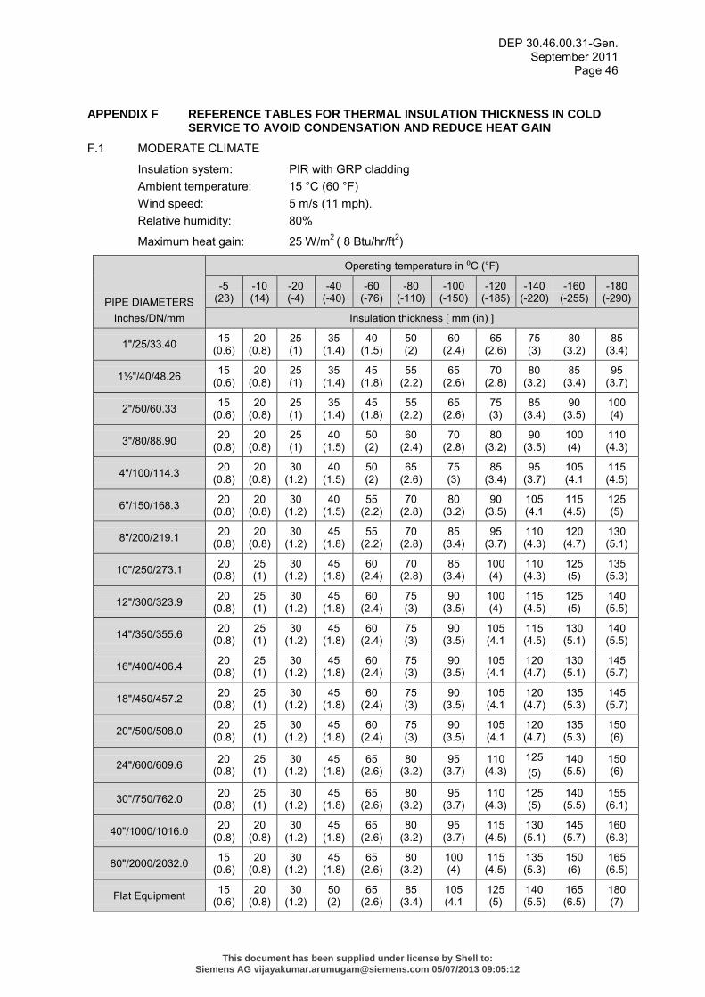
DEP 30.46.00.31-Gen. September 2011
Page 46
APPENDIX F REFERENCE TABLES FOR THERMAL INSULATION THICKNESS IN COLD SERVICE TO AVOID CONDENSATION AND REDUCE HEAT GAIN
F.1 MODERATE CLIMATE
Insulation system: PIR with GRP cladding Ambient temperature: 15 °C (60 °F) Wind speed: 5 m/s (11 mph). Relative humidity: 80%
Maximum heat gain: 25 W/m2 ( 8 Btu/hr/ft2)
PIPE DIAMETERS Inches/DN/mm
Operating temperature in ⁰C (°F)
-5 (23)
-10 (14)
-20 (-4)
-40 (-40)
-60 (-76)
-80 (-110)
-100 (-150)
-120 (-185)
-140 (-220)
-160 (-255)
-180 (-290)
Insulation thickness [ mm (in) ]
1"/25/33.40 15 (0.6)
20 (0.8)
25 (1)
35 (1.4)
40 (1.5)
50 (2)
60 (2.4)
65 (2.6)
75 (3)
80 (3.2)
85 (3.4)
1½"/40/48.26 15 (0.6)
20 (0.8)
25 (1)
35 (1.4)
45 (1.8)
55 (2.2)
65 (2.6)
70 (2.8)
80 (3.2)
85 (3.4)
95 (3.7)
2"/50/60.33 15 (0.6)
20 (0.8)
25 (1)
35 (1.4)
45 (1.8)
55 (2.2)
65 (2.6)
75 (3)
85 (3.4)
90 (3.5)
100 (4)
3"/80/88.90 20 (0.8)
20 (0.8)
25 (1)
40 (1.5)
50 (2)
60 (2.4)
70 (2.8)
80 (3.2)
90 (3.5)
100 (4)
110 (4.3)
4"/100/114.3 20 (0.8)
20 (0.8)
30 (1.2)
40 (1.5)
50 (2)
65 (2.6)
75 (3)
85 (3.4)
95 (3.7)
105 (4.1
115 (4.5)
6"/150/168.3 20 (0.8)
20 (0.8)
30 (1.2)
40 (1.5)
55 (2.2)
70 (2.8)
80 (3.2)
90 (3.5)
105 (4.1
115 (4.5)
125 (5)
8"/200/219.1 20 (0.8)
20 (0.8)
30 (1.2)
45 (1.8)
55 (2.2)
70 (2.8)
85 (3.4)
95 (3.7)
110 (4.3)
120 (4.7)
130 (5.1)
10"/250/273.1 20 (0.8)
25 (1)
30 (1.2)
45 (1.8)
60 (2.4)
70 (2.8)
85 (3.4)
100 (4)
110 (4.3)
125 (5)
135 (5.3)
12"/300/323.9 20 (0.8)
25 (1)
30 (1.2)
45 (1.8)
60 (2.4)
75 (3)
90 (3.5)
100 (4)
115 (4.5)
125 (5)
140 (5.5)
14"/350/355.6 20 (0.8)
25 (1)
30 (1.2)
45 (1.8)
60 (2.4)
75 (3)
90 (3.5)
105 (4.1
115 (4.5)
130 (5.1)
140 (5.5)
16"/400/406.4 20 (0.8)
25 (1)
30 (1.2)
45 (1.8)
60 (2.4)
75 (3)
90 (3.5)
105 (4.1
120 (4.7)
130 (5.1)
145 (5.7)
18"/450/457.2 20 (0.8)
25 (1)
30 (1.2)
45 (1.8)
60 (2.4)
75 (3)
90 (3.5)
105 (4.1
120 (4.7)
135 (5.3)
145 (5.7)
20"/500/508.0 20 (0.8)
25 (1)
30 (1.2)
45 (1.8)
60 (2.4)
75 (3)
90 (3.5)
105 (4.1
120 (4.7)
135 (5.3)
150 (6)
24"/600/609.6 20 (0.8)
25 (1)
30 (1.2)
45 (1.8)
65 (2.6)
80 (3.2)
95 (3.7)
110 (4.3)
125 (5)
140 (5.5)
150 (6)
30"/750/762.0 20 (0.8)
25 (1)
30 (1.2)
45 (1.8)
65 (2.6)
80 (3.2)
95 (3.7)
110 (4.3)
125 (5)
140 (5.5)
155 (6.1)
40"/1000/1016.0 20 (0.8)
20 (0.8)
30 (1.2)
45 (1.8)
65 (2.6)
80 (3.2)
95 (3.7)
115 (4.5)
130 (5.1)
145 (5.7)
160 (6.3)
80"/2000/2032.0 15 (0.6)
20 (0.8)
30 (1.2)
45 (1.8)
65 (2.6)
80 (3.2)
100 (4)
115 (4.5)
135 (5.3)
150 (6)
165 (6.5)
Flat Equipment 15 (0.6)
20 (0.8)
30 (1.2)
50 (2)
65 (2.6)
85 (3.4)
105 (4.1
125 (5)
140 (5.5)
165 (6.5)
180 (7)
This document has been supplied under license by Shell to:Siemens AG [email protected] 05/07/2013 09:05:12
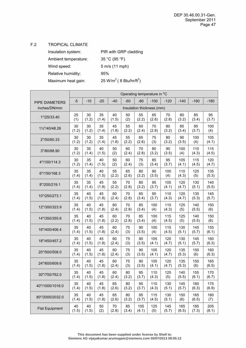
DEP 30.46.00.31-Gen. September 2011
Page 47
F.2 TROPICAL CLIMATE
Insulation system: PIR with GRP cladding
Ambient temperature: 35 °C (95 °F)
Wind speed: 5 m/s (11 mph)
Relative humidity: 95%
Maximum heat gain: 25 W/m2 ( 8 Btu/hr/ft2)
PIPE DIAMETERS Inches/DN/mm
Operating temperature in ⁰C
-5 -10 -20 -40 -60 -80 -100 -120 -140 -160 -180
Insulation thickness (mm)
1"/25/33.40 25 (1)
30 (1.2)
35 (1.4)
40 (1.5)
50 (2)
55 (2.2)
65 (2.6)
70 (2.8)
80 (3.2)
85 (3.4)
95 (3.7)
1½"/40/48.26 30 (1.2)
30 (1.2)
35 (1.4)
45 (1.8)
55 (2.2)
60 (2.4)
70 (2.8)
80 (3.2)
85 (3.4)
95 (3.7)
100 (4)
2"/50/60.33 30 (1.2)
30 (1.2)
35 (1.4)
45 (1.8)
55 (2.2)
65 (2.6)
75 (3)
80 (3.2)
90 (3.5)
100 (4)
105 (4.1)
3"/80/88.90 30 (1.2)
35 (1.4)
40 (1.5)
50 (2)
60 (2.4)
70 (2.8)
80 (3.2)
90 (3.5)
100 (4)
110 (4.3)
115 (4.5)
4"/100/114.3 30 (1.2)
35 (1.4)
40 (1.5)
50 (2)
60 (2.4)
75 (3)
85 (3.4)
95 (3.7)
105 (4.1)
115 (4.5)
120 (4.7)
6"/150/168.3 35 (1.4)
35 (1.4)
40 (1.5)
55 (2.2)
65 (2.6)
80 (3.2)
90 (3.5)
100 (4)
110 (4.3)
125 (5)
135 (5.3)
8"/200/219.1 35 (1.4)
35 (1.4)
45 (1.8)
55 (2.2)
70 (2.8)
80 (3.2)
95 (3.7)
105 (4.1)
120 (4.7)
130 (5.1)
140 (5.5)
10"/250/273.1 35 (1.4)
40 (1.5)
45 (1.8)
60 (2.4)
70 (2.8)
85 (3.4)
95 (3.7)
110 (4.3)
120 (4.7)
135 (5.3)
145 (5.7)
12"/300/323.9 35 (1.4)
40 (1.5)
45 (1.8)
60 (2.4)
70 (2.8)
85 (3.4)
100 (4)
110 (4.3)
125 (5)
140 (5.5)
150 (6)
14"/350/355.6 35 (1.4)
40 (1.5)
45 (1.8)
60 (2.2)
70 (2.8)
85 (3.4)
100 (4)
115 (4.5)
125 (5)
140 (5.5)
150 (6)
16"/400/406.4 35 (1.4)
40 (1.5)
45 (1.8)
60 (2.4)
75 (3)
90 (3.5)
100 (4)
115 (4.5)
130 (5.1)
145 (5.7)
155 (6.1)
18"/450/457.2 35 (1.4)
40 (1.5)
45 (1.8)
60 (2.4)
75 (3)
90 (3.5)
105 (4.1)
120 (4.7)
130 (5.1)
145 (5.7)
160 (6.3)
20"/500/508.0 35 (1.4)
40 (1.5)
45 (1.8)
60 (2.4)
75 (3)
90 (3.5)
105 (4.1)
120 (4.7)
135 (5.3)
150 (6)
160 (6.3)
24"/600/609.6 35 (1.4)
40 (1.5)
45 (1.8)
60 (2.4)
75 (3)
90 (3.5)
105 (4.1)
120 (4.7)
135 (5.3)
150 (6)
165 (6.5)
30"/750/762.0 35 (1.4)
40 (1.5)
45 (1.8)
60 (2.4)
80 (3.2)
95 (3.7)
110 (4.3)
125 (5)
140 (5.5)
155 (6.1)
170 (6.7)
40"/1000/1016.0 35 (1.4)
40 (1.5)
45 (1.8)
65 (2.6)
80 (3.2)
95 (3.7)
110 (4.3)
130 (5.1)
145 (5.7)
160 (6.3)
175 (6.9)
80"/2000/2032.0 35 (1.4)
40 (1.5)
45 (1.8)
65 (2.6)
80 (3.2)
95 (3.7)
115 (4.5)
130 (5.1)
150 (6)
165 (6.5)
180 (7)
Flat Equipment 40 (1.5)
40 (1.5)
50 (2)
70 (2.8)
85 (3.4)
105 (4.1)
125 (5)
145 (5.7)
165 (6.5)
185 (7.3)
205 (8.1)
This document has been supplied under license by Shell to:Siemens AG [email protected] 05/07/2013 09:05:12
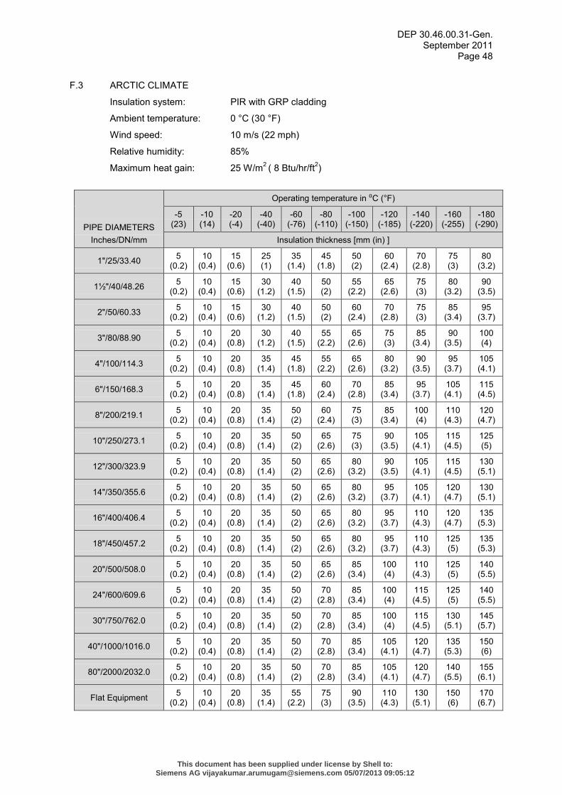
DEP 30.46.00.31-Gen. September 2011
Page 48
F.3 ARCTIC CLIMATE
Insulation system: PIR with GRP cladding
Ambient temperature: 0 °C (30 °F)
Wind speed: 10 m/s (22 mph)
Relative humidity: 85%
Maximum heat gain: 25 W/m2 ( 8 Btu/hr/ft2)
PIPE DIAMETERS Inches/DN/mm
Operating temperature in ⁰C (°F)
-5 (23)
-10 (14)
-20 (-4)
-40 (-40)
-60 (-76)
-80 (-110)
-100 (-150)
-120 (-185)
-140 (-220)
-160 (-255)
-180 (-290)
Insulation thickness [mm (in) ]
1"/25/33.40 5 (0.2)
10 (0.4)
15 (0.6)
25 (1)
35 (1.4)
45 (1.8)
50 (2)
60 (2.4)
70 (2.8)
75 (3)
80 (3.2)
1½"/40/48.26 5 (0.2)
10 (0.4)
15 (0.6)
30 (1.2)
40 (1.5)
50 (2)
55 (2.2)
65 (2.6)
75 (3)
80 (3.2)
90 (3.5)
2"/50/60.33 5 (0.2)
10 (0.4)
15 (0.6)
30 (1.2)
40 (1.5)
50 (2)
60 (2.4)
70 (2.8)
75 (3)
85 (3.4)
95 (3.7)
3"/80/88.90 5 (0.2)
10 (0.4)
20 (0.8)
30 (1.2)
40 (1.5)
55 (2.2)
65 (2.6)
75 (3)
85 (3.4)
90 (3.5)
100 (4)
4"/100/114.3 5 (0.2)
10 (0.4)
20 (0.8)
35 (1.4)
45 (1.8)
55 (2.2)
65 (2.6)
80 (3.2)
90 (3.5)
95 (3.7)
105 (4.1)
6"/150/168.3 5 (0.2)
10 (0.4)
20 (0.8)
35 (1.4)
45 (1.8)
60 (2.4)
70 (2.8)
85 (3.4)
95 (3.7)
105 (4.1)
115 (4.5)
8"/200/219.1 5 (0.2)
10 (0.4)
20 (0.8)
35 (1.4)
50 (2)
60 (2.4)
75 (3)
85 (3.4)
100 (4)
110 (4.3)
120 (4.7)
10"/250/273.1 5 (0.2)
10 (0.4)
20 (0.8)
35 (1.4)
50 (2)
65 (2.6)
75 (3)
90 (3.5)
105 (4.1)
115 (4.5)
125 (5)
12"/300/323.9 5 (0.2)
10 (0.4)
20 (0.8)
35 (1.4)
50 (2)
65 (2.6)
80 (3.2)
90 (3.5)
105 (4.1)
115 (4.5)
130 (5.1)
14"/350/355.6 5 (0.2)
10 (0.4)
20 (0.8)
35 (1.4)
50 (2)
65 (2.6)
80 (3.2)
95 (3.7)
105 (4.1)
120 (4.7)
130 (5.1)
16"/400/406.4 5 (0.2)
10 (0.4)
20 (0.8)
35 (1.4)
50 (2)
65 (2.6)
80 (3.2)
95 (3.7)
110 (4.3)
120 (4.7)
135 (5.3)
18"/450/457.2 5 (0.2)
10 (0.4)
20 (0.8)
35 (1.4)
50 (2)
65 (2.6)
80 (3.2)
95 (3.7)
110 (4.3)
125 (5)
135 (5.3)
20"/500/508.0 5 (0.2)
10 (0.4)
20 (0.8)
35 (1.4)
50 (2)
65 (2.6)
85 (3.4)
100 (4)
110 (4.3)
125 (5)
140 (5.5)
24"/600/609.6 5 (0.2)
10 (0.4)
20 (0.8)
35 (1.4)
50 (2)
70 (2.8)
85 (3.4)
100 (4)
115 (4.5)
125 (5)
140 (5.5)
30"/750/762.0 5 (0.2)
10 (0.4)
20 (0.8)
35 (1.4)
50 (2)
70 (2.8)
85 (3.4)
100 (4)
115 (4.5)
130 (5.1)
145 (5.7)
40"/1000/1016.0 5 (0.2)
10 (0.4)
20 (0.8)
35 (1.4)
50 (2)
70 (2.8)
85 (3.4)
105 (4.1)
120 (4.7)
135 (5.3)
150 (6)
80"/2000/2032.0 5 (0.2)
10 (0.4)
20 (0.8)
35 (1.4)
50 (2)
70 (2.8)
85 (3.4)
105 (4.1)
120 (4.7)
140 (5.5)
155 (6.1)
Flat Equipment 5 (0.2)
10 (0.4)
20 (0.8)
35 (1.4)
55 (2.2)
75 (3)
90 (3.5)
110 (4.3)
130 (5.1)
150 (6)
170 (6.7)
This document has been supplied under license by Shell to:Siemens AG [email protected] 05/07/2013 09:05:12
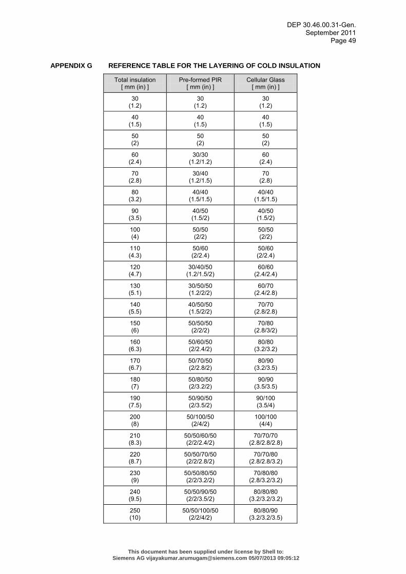
DEP 30.46.00.31-Gen. September 2011
Page 49
APPENDIX G REFERENCE TABLE FOR THE LAYERING OF COLD INSULATION
Total insulation [ mm (in) ]
Pre-formed PIR [ mm (in) ]
Cellular Glass [ mm (in) ]
30 (1.2)
30 (1.2)
30 (1.2)
40 (1.5)
40 (1.5)
40 (1.5)
50 (2)
50 (2)
50 (2)
60 (2.4)
30/30 (1.2/1.2)
60 (2.4)
70 (2.8)
30/40 (1.2/1.5)
70 (2.8)
80 (3.2)
40/40 (1.5/1.5)
40/40 (1.5/1.5)
90 (3.5)
40/50 (1.5/2)
40/50 (1.5/2)
100 (4)
50/50 (2/2)
50/50 (2/2)
110 (4.3)
50/60 (2/2.4)
50/60 (2/2.4)
120 (4.7)
30/40/50 (1.2/1.5/2)
60/60 (2.4/2.4)
130 (5.1)
30/50/50 (1.2/2/2)
60/70 (2.4/2.8)
140 (5.5)
40/50/50 (1.5/2/2)
70/70 (2.8/2.8)
150 (6)
50/50/50 (2/2/2)
70/80 (2.8/3/2)
160 (6.3)
50/60/50 (2/2.4/2)
80/80 (3.2/3.2)
170 (6.7)
50/70/50 (2/2.8/2)
80/90 (3.2/3.5)
180 (7)
50/80/50 (2/3.2/2)
90/90 (3.5/3.5)
190 (7.5)
50/90/50 (2/3.5/2)
90/100 (3.5/4)
200 (8)
50/100/50 (2/4/2)
100/100 (4/4)
210 (8.3)
50/50/60/50 (2/2/2.4/2)
70/70/70 (2.8/2.8/2.8)
220 (8.7)
50/50/70/50 (2/2/2.8/2)
70/70/80 (2.8/2.8/3.2)
230 (9)
50/50/80/50 (2/2/3.2/2)
70/80/80 (2.8/3.2/3.2)
240 (9.5)
50/50/90/50 (2/2/3.5/2)
80/80/80 (3.2/3.2/3.2)
250 (10)
50/50/100/50 (2/2/4/2)
80/80/90 (3.2/3.2/3.5)
This document has been supplied under license by Shell to:Siemens AG [email protected] 05/07/2013 09:05:12
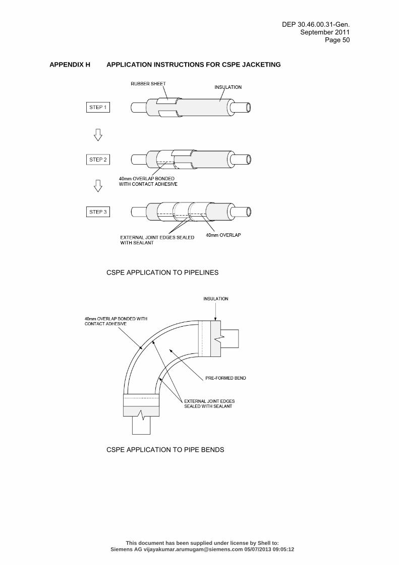
DEP 30.46.00.31-Gen. September 2011
Page 50
APPENDIX H APPLICATION INSTRUCTIONS FOR CSPE JACKETING
CSPE APPLICATION TO PIPELINES
CSPE APPLICATION TO PIPE BENDS
This document has been supplied under license by Shell to:Siemens AG [email protected] 05/07/2013 09:05:12
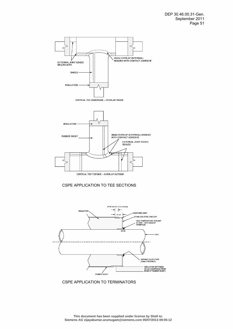
DEP 30.46.00.31-Gen. September 2011
Page 51
CSPE APPLICATION TO TEE SECTIONS
CSPE APPLICATION TO TERMINATORS
30 50 mm (1½ 2 in ) overlap
50 100
This document has been supplied under license by Shell to:Siemens AG [email protected] 05/07/2013 09:05:12
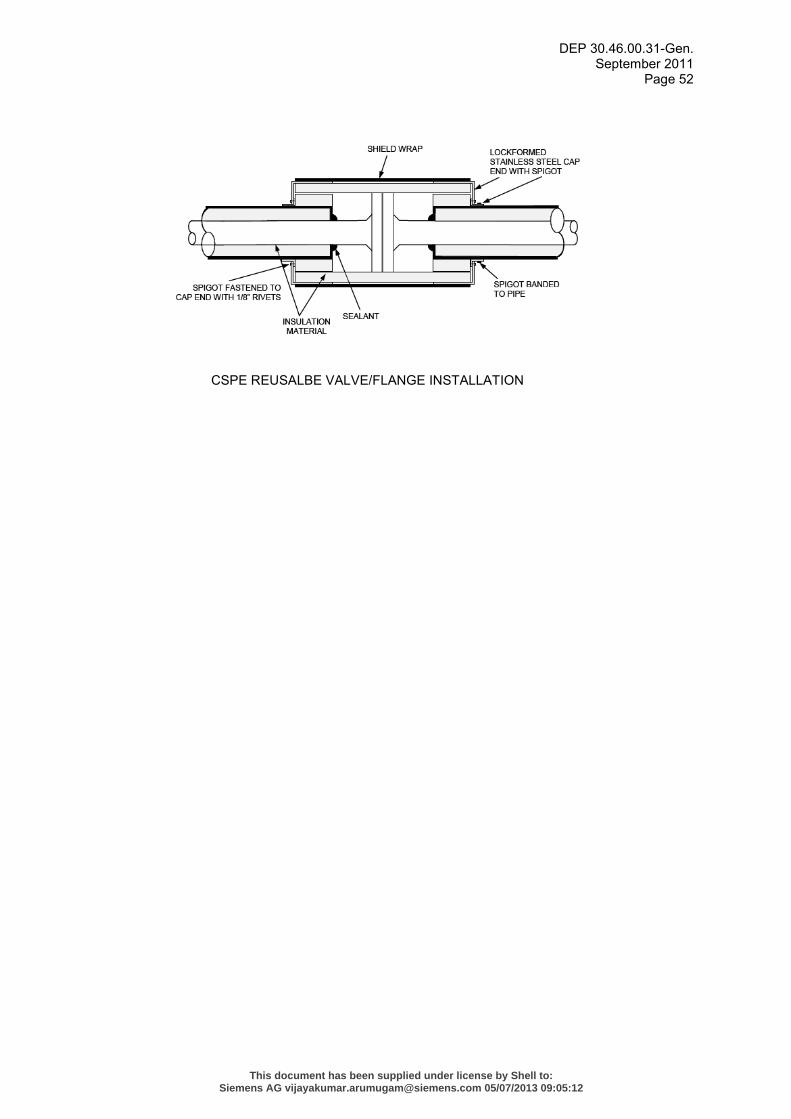
DEP 30.46.00.31-Gen. September 2011
Page 52
CSPE REUSALBE VALVE/FLANGE INSTALLATION
This document has been supplied under license by Shell to:Siemens AG [email protected] 05/07/2013 09:05:12
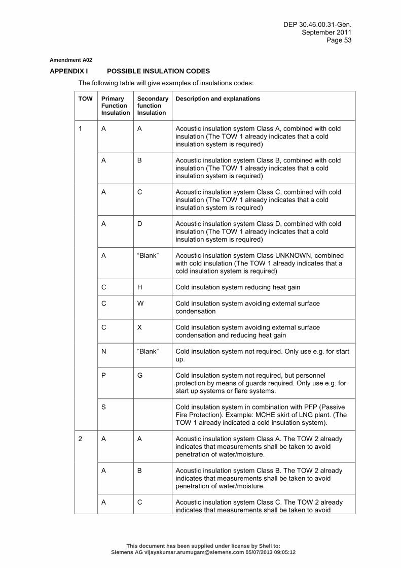
DEP 30.46.00.31-Gen. September 2011
Page 53
Amendment A02
APPENDIX I POSSIBLE INSULATION CODES
The following table will give examples of insulations codes:
TOW Primary Function Insulation
Secondary function Insulation
Description and explanations
1 A A Acoustic insulation system Class A, combined with cold insulation (The TOW 1 already indicates that a cold insulation system is required)
A B Acoustic insulation system Class B, combined with cold insulation (The TOW 1 already indicates that a cold insulation system is required)
A C Acoustic insulation system Class C, combined with cold insulation (The TOW 1 already indicates that a cold insulation system is required)
A D Acoustic insulation system Class D, combined with cold insulation (The TOW 1 already indicates that a cold insulation system is required)
A “Blank” Acoustic insulation system Class UNKNOWN, combined with cold insulation (The TOW 1 already indicates that a cold insulation system is required)
C H Cold insulation system reducing heat gain
C W Cold insulation system avoiding external surface condensation
C X Cold insulation system avoiding external surface condensation and reducing heat gain
N “Blank” Cold insulation system not required. Only use e.g. for start up.
P G Cold insulation system not required, but personnel protection by means of guards required. Only use e.g. for start up systems or flare systems.
S Cold insulation system in combination with PFP (Passive Fire Protection). Example: MCHE skirt of LNG plant. (The TOW 1 already indicated a cold insulation system).
2 A A Acoustic insulation system Class A. The TOW 2 already indicates that measurements shall be taken to avoid penetration of water/moisture.
A B Acoustic insulation system Class B. The TOW 2 already indicates that measurements shall be taken to avoid penetration of water/moisture.
A C Acoustic insulation system Class C. The TOW 2 already indicates that measurements shall be taken to avoid
This document has been supplied under license by Shell to:Siemens AG [email protected] 05/07/2013 09:05:12
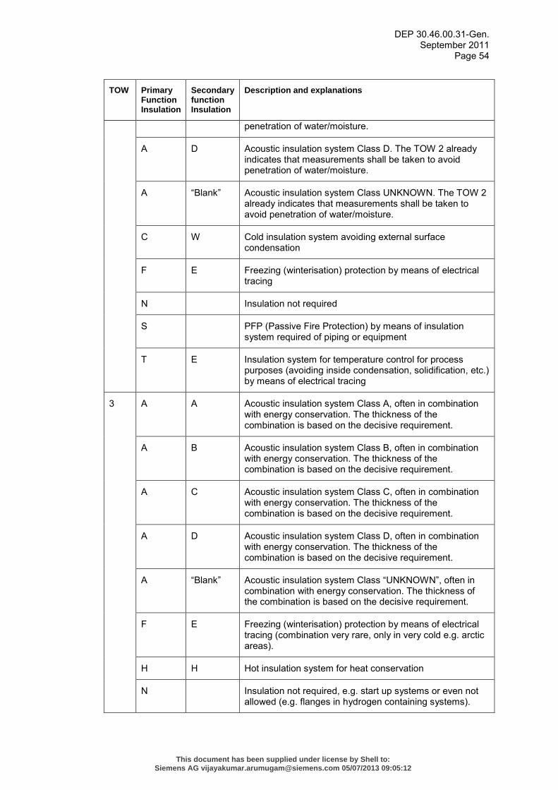
DEP 30.46.00.31-Gen. September 2011
Page 54
TOW Primary Function Insulation
Secondary function Insulation
Description and explanations
penetration of water/moisture.
A D Acoustic insulation system Class D. The TOW 2 already indicates that measurements shall be taken to avoid penetration of water/moisture.
A “Blank” Acoustic insulation system Class UNKNOWN. The TOW 2 already indicates that measurements shall be taken to avoid penetration of water/moisture.
C W Cold insulation system avoiding external surface condensation
F E Freezing (winterisation) protection by means of electrical tracing
N Insulation not required
S PFP (Passive Fire Protection) by means of insulation system required of piping or equipment
T E Insulation system for temperature control for process purposes (avoiding inside condensation, solidification, etc.) by means of electrical tracing
3 A A Acoustic insulation system Class A, often in combination with energy conservation. The thickness of the combination is based on the decisive requirement.
A B Acoustic insulation system Class B, often in combination with energy conservation. The thickness of the combination is based on the decisive requirement.
A C Acoustic insulation system Class C, often in combination with energy conservation. The thickness of the combination is based on the decisive requirement.
A D Acoustic insulation system Class D, often in combination with energy conservation. The thickness of the combination is based on the decisive requirement.
A “Blank” Acoustic insulation system Class “UNKNOWN”, often in combination with energy conservation. The thickness of the combination is based on the decisive requirement.
F E Freezing (winterisation) protection by means of electrical tracing (combination very rare, only in very cold e.g. arctic areas).
H H Hot insulation system for heat conservation
N Insulation not required, e.g. start up systems or even not allowed (e.g. flanges in hydrogen containing systems).
This document has been supplied under license by Shell to:Siemens AG [email protected] 05/07/2013 09:05:12
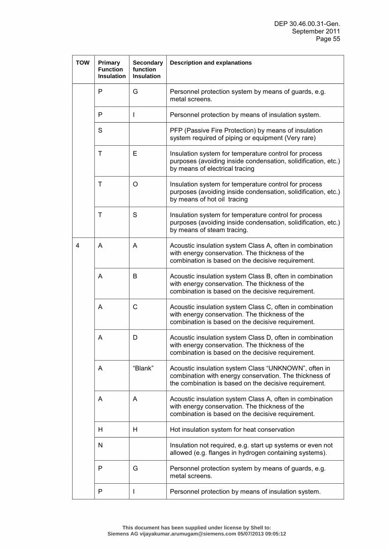
DEP 30.46.00.31-Gen. September 2011
Page 55
TOW Primary Function Insulation
Secondary function Insulation
Description and explanations
P G Personnel protection system by means of guards, e.g. metal screens.
P I Personnel protection by means of insulation system.
S PFP (Passive Fire Protection) by means of insulation system required of piping or equipment (Very rare)
T E Insulation system for temperature control for process purposes (avoiding inside condensation, solidification, etc.) by means of electrical tracing
T O Insulation system for temperature control for process purposes (avoiding inside condensation, solidification, etc.) by means of hot oil tracing
T S Insulation system for temperature control for process purposes (avoiding inside condensation, solidification, etc.) by means of steam tracing.
4 A A Acoustic insulation system Class A, often in combination with energy conservation. The thickness of the combination is based on the decisive requirement.
A B Acoustic insulation system Class B, often in combination with energy conservation. The thickness of the combination is based on the decisive requirement.
A C Acoustic insulation system Class C, often in combination with energy conservation. The thickness of the combination is based on the decisive requirement.
A D Acoustic insulation system Class D, often in combination with energy conservation. The thickness of the combination is based on the decisive requirement.
A “Blank” Acoustic insulation system Class “UNKNOWN”, often in combination with energy conservation. The thickness of the combination is based on the decisive requirement.
A A Acoustic insulation system Class A, often in combination with energy conservation. The thickness of the combination is based on the decisive requirement.
H H Hot insulation system for heat conservation
N Insulation not required, e.g. start up systems or even not allowed (e.g. flanges in hydrogen containing systems).
P G Personnel protection system by means of guards, e.g. metal screens.
P I Personnel protection by means of insulation system.
This document has been supplied under license by Shell to:Siemens AG [email protected] 05/07/2013 09:05:12
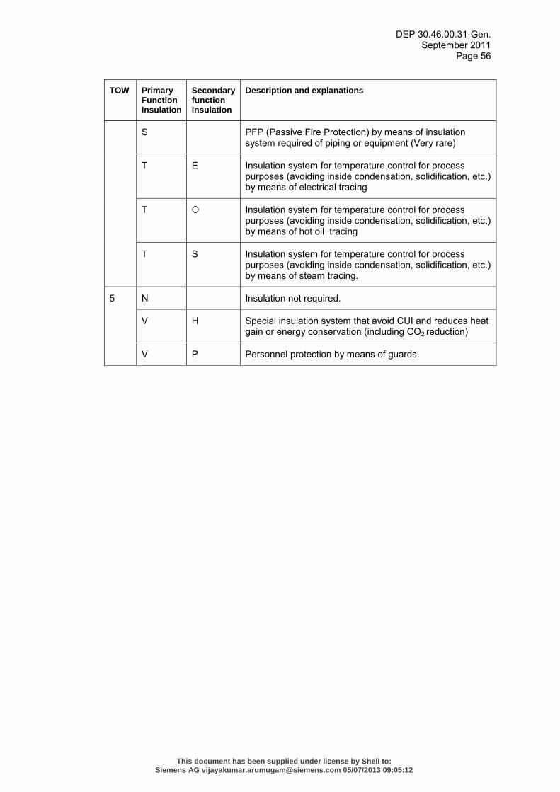
DEP 30.46.00.31-Gen. September 2011
Page 56
TOW Primary Function Insulation
Secondary function Insulation
Description and explanations
S PFP (Passive Fire Protection) by means of insulation system required of piping or equipment (Very rare)
T E Insulation system for temperature control for process purposes (avoiding inside condensation, solidification, etc.) by means of electrical tracing
T O Insulation system for temperature control for process purposes (avoiding inside condensation, solidification, etc.) by means of hot oil tracing
T S Insulation system for temperature control for process purposes (avoiding inside condensation, solidification, etc.) by means of steam tracing.
5 N Insulation not required.
V H Special insulation system that avoid CUI and reduces heat gain or energy conservation (including CO2 reduction)
V P Personnel protection by means of guards.
This document has been supplied under license by Shell to:Siemens AG [email protected] 05/07/2013 09:05:12