Embed Size (px)
Citation preview

TM 11-6625-363-1 ~ DEPAITIENT OF THE ARIY TECIIICAL IAIUA
OPERATOR, ORGANIZATIONAL nELD AND DEPOT MAfflTENANCE MANUAL
TESTER, FUEL QUANTITY GAGE TYPE MD-I
This copy is a reprint which includes curtent pages from Changes 1.
BEADQUA.rE•S, DEPARTMENT OF THE ARII JUNE 1960

HEADQUARTERS, DEPARTMENT OF THE ARMY WA~HINGTON 25, D. C., 16 June 1960
TM 11-6625--363-15 (a reprint of AF TO 33D2-2-5-1, 1 May 1956, and TO 33D2-3-6-4, 1 May 1956,) is published for the use of Army personnel.
By Order of Wilber M. Brucker, Secretary of the Army:
Official: R. V. LEE,
Major General, United States Army, The Ac!jutant General.
Distribution :
Active Army :
L. L. LEMNITZER, General, United Statea Army,
Chief of Sta,ff.
To ~ distributed in accordance with DA Form 12-7 requirement> for Ti\1 11 Series (U!\'CL) Plus the following additional formula :
ASA (21
Tech Stf. DA (I l except CSigO (20l. CofT (201
USA Aim & Elct Rd C I l CSA Arctic Te~t Rd < .. n MOW (I)
Seventh US :\ rmy ( ~ I
NG : State AG (3) .
USAR : None.
For explanatiou of abbre,· iatiou ~ u~cd. sec AR-320-50.
Eighth US Army ( 4)
Corps (2) CS~!A (2)
L"nits org uuder fol TOE :
11-155 (2) 11-587 (2)
11-500 1.-\ .-\-AEl <2l
• (

•
• )
TM 11-6621-361-15 c 1
TECHNICAL MANUAL
Operator, Oraanlzallonal, Flelcl, ancl Depot Maintenance Manval, TESTEI, FUEL QUANtiTY GAGE TYPE MD-1
TM 11-6625-363-151
CHANoa No. 1
HEADQUARTERS, DEPARTMENT OF THE ARMY W A8RINCJTON 26, D.C., 11 Jut~e 19(13
TM 11-6625-363-15, 16 June UMIO, is chanced aa follows:
Page I. Add the followiq after parapapb 1-3.
1-1.1. Index of Publications Refer to the latest issue of DA Pam 31()-4 to deter
mine whether there are new editions, changes, or additional publications pertaining to the equipment. DA Pam 31()-4 is a current index of technical manuals, tecbn~l bulletins, supply bulletins, lubrication orden, and modification work orden that are available throuch publications supply channels. The index lists the individual parte (-10, -20, -35P, etc.) and the latest changes to and revisions of each equipment publication.
1-3.2. Forms ancl Records a. Report. of Main~mm&ce and UNitlliajaclor1J
Bquiprnmt. Uee equipment forma and recorda in accordance with instructions in TM 38-7SO.
b. Rqori of~ or lwaproper Sl&iprnmt. Fili out and forward DD Form 6 (Report of Damaged or Improper Shipment) aa preecribed in AR 7()()-58 (Army), NAVBANDA Publication 378 (Navy), and AFR 71-4 (Air Force).
c. Cmnmata on MtmUGl. Forward all comments oa this publication direct to: Commanding Officer, U.S. Army Electronics Materiel Support Agency, ATTN: BELMB-MP, Fort Monmouth, N.J; (DA Form 1598 (Record of Comments on Publications), DA Form 2496 (Disposition Form), or letter may be ueed.) . Pa,e 7. Add the following after section. IV.
Section IV.1. MAINTENANCE INSTRUCTIONS
4.1-1. Scope of Operator's Maintenance The maintenance duties Wlligned to the operator
of the tester are listed below, together with a reference to the paragraphs covering the specific maintenance function. The duties asaigned do not require tools or test equipment other than those iasu~ with the equipment.
a. Daily preventive maintenance checks and services {par. 4.1-3).
b. Weekly preventive maintenance checks and services {par. 4.1-4).
c. Cleaning {pan. 5-8 and 5-9). d. Lubrication (par. 5-14).
4.1-2. Operator's PNventlve Maintenance Operator's preventive maintenance is the sys
tematic care, servicing, and inspection of equipment to prevent the occurreace of trouble, to reduce doumtiN, and to IUISUre that the equipment is eerviceable.
a. Syllan.alic Care. The procedures given in
paragraphs 4.1-3, 4.1-4, 5-8, and 5-9, cover routine systematic care and cleaning eaeential to proper upkeep and operation of the equipment.
b. PreHnlive M ain~mm&ce Cl&ecb and &rvicu. The preventive maintenance checks and services cbarte (pan. 4.1-3, 4.1-4, and 4.1-7) outline functions to be performed at specific intervals. These checks and services are designed to maintain Army electronic equipment in · a combat serviceable condition; that . is, in good general (physical) condition and . in good c)perating condition. To assist operaton in maintaining combat serviceability, the charta indicate what to check, bow to check, and what the normal conditions are; the Refemu:u column lists the paragraphs that contain detailed repair or replacement procedures. If the defect cannot be remedied by the operator, higher echelon maintenance or repair is requiied. Recorda and reports of these checks and services must be made in accordance with TM 38-7:JO .
1
Digitized by Coogle

4.1-3. DaHy Preventive Maintenance Checks ancl Ser-.ices Chart
-,::- 1'-1 ......... ..... 1
Teeter ________________ .. ____ Cbeck equipnell\lor com......._ aod paera1 cqoclidoa. ___ Pan II, &c. 1. 2 Exterior eurfacee ••..•••.• ___ Cleua uterior eurfacee ~ the equipmeo\ •• __ ••••••••••• __ P..._WaadH. 3 Exteraal ~--------- llllpeCt. exterD&l ~for breabp aod &rm .. tiDe. 4 or...------- . ------------- l....,ec\ froet-puel ..... wiDdowa for damapd hOUiin&,
brokea ...... pbytieal damap, dU8t, or moilture. 6 Koobe aod ewitchee. _ •••••• _ • Duriaa opemioD eheck kDObe aod ewitchee for proper
mecbaoical aetioa. Act.ioa mOlt be IQit.ive wit.hou\ backlMb, biDdiDc, or eenpiac.
I ~~------------------ QuriDI operatioa, be &len for aoy unu.ual ~ormance, ~. or eoaditioa.
4.1-4. Weekly Preventive Maintenance Checks ancl Services Chart
"11:.- . ._ ......... ....... -
1 ~~-----·--------------- llllpeCt. ut.ernal cabl• for cut.l, cradtecl, or pupcl jacket.l, frayiDc, or kiab.
2 ~are __________________
llllpeCt. all exterior hardware for looeene~~ aod damap. The teeter cover, carryiDc haDclle, hiDpe, iaput biDdinc poete, aod all bolta aod ecrewe mOlt be ticht aod DOt.
a ~tioo- ----------.-----
damapcl. l....,ec\ tbe equipmen\ to determiDe. &bat i\ il free of bare .,... ,.. aod corroeioo . If &hele coodit.ione exilt,
refer to lUPer echeloe for repair. 4 Lubrication ..•.•.......••..• -Lubricate the equipmeot iD accordance with ptn~raph 6-14.
4.1-5. Scope of Second Echelon Maintenance services chart (par. 4.1-7) once each month. A month is defined aa approximately 30 calendar days of 8-hour-per~y operation. If the equipment is operated 16 hours a day, the monthly preventive maintenance checks and services abould be perfo.,ned at 15-day intervals. Adjustment of the maintenance interval must be made to compenaate for any unusual operating conditions. Equipment maintained in a standby (ready for immediate operation) condition must have monthly preventive maintenance checks and services performed on it. Equipment in limited storage (requires service before operation) does not require monthly preventive maintenance.
The maintenance duties assigned to the organiational maintenance repairman of the teeter are listed below, together with a reference to the paragraphs covering the specific function. The duties 881iped do not require tools or ieet equipment other than tboee issued with the equipment.
o. Monthly preventive maintenance checks and eervicee (par. 4.1-7).
b. Rustproo&ng and painting (par. 5-10).
4.1-6. Monthly Maintenance Perform the maintenance functions indicated in
the monthly preventive maintenance checks and
4.1-7. Monthly Preventive Checks oncl Services Chart
1'-1 •••••••• 1 Publicatiooe. _ •.••.• - •.••. _ _ I....,ec\ mutual for oorraplet.eae. aod t.o eee if it il iD .able I>A Pam a1o-t.
coodltioe, wttbou\ milliDI IMIPI· Be lUre tba\ all
2
chaDpa t.o tbe mutual are oe haod. 2 Mocli&aat.ion work urderw..... Check to 1ee &bat all URGENT MWO'a have beeD applied I>A Pam llH.
aod &bat all ROUTINE MWO'a have beeD acbeciWecl. a CompJeteDe. •• ----------- -- Check Uaeequipmentforcompletebe. aodpaeralCODditioD. Part II, fie. 1. 4 CleM''----.------------- C1eua exterior •rfMII of tbe equipmea\ .... ------------- Par. H aod H. .......
Digitized by Google
•
•

• I
-___ , ___ ·-----,----- -------·-----------··---------
5 Preeervat.ioa ••••••• ---------
6 External recept.aelea ...•..... 7 l>eeciccator tube ........... . 8 Gl .. _ .... . .... . ........ ·.·.
9 Cablea_ ••.•.•••••••••••• • :.
10 Hard•·are. _ . _ . . . .......... .
II Lubrication ................ . 12 Knobe &Qd ewitchea ......... .
13 l,erformaoce •..•..••........
llllpeCt tbe equipment to determine tf:aat it il free of bare Par. 6-10. 1p0t., ruat, and cori'Oiioo.
ID~~peet. external recept.aclea for bPeakap and firm eeat.ing. ViiUally check condition of cleaiccator tube. (par. 1-15) . . .. Par. 5-3. l011peet front-panel gla. wiodon for damapd housing,
broken gl .. , phyeical damap, duet, or moieture. l011peet external cablea for cutl, cracked, or gouced jacketa,
fraying, or kinka. l011peet all exterior and interior hardware for •~- and
damage. The teater cover, carrying handle, biopa, inRUt binding J)Ot.ta, and all bolta and ecre.·• mUit be t.ilht and not damapd.
Lubricate the equipment in accordance with paraaraph 6-14. During operation (item 13), oblerve that the mechanical
action or each knob and -.·itch il tmooth and free or external or internal binding.
Be alert for any abnormal condition when operating the equipment. I .
Page1. Deleteparngraphs5-1,5-2,5-5,and 5-6. surfncc down to the bnre metal. Obtain a bright Page 8. Delete paragraph 5-10 and table IV smooth finish.
and substitute: b. Painting. Remove rust and corrosion from 5-10. RustproofilltJ and Palntlnt~ metal surfaces by lightly sanding them with fine
a. Rv.Mproofinl. When the finish on the tester sandpaper. Brush two thin coats of paint on the hu become badly acarred or dam,.ged, rust and bare metal to protect it from further corrosion. corrosion can be prevented by touching up the bared Refer to the applicable cleaning and refinishing eurfacee. Use No. 000 sandpaper to clean the practices specified in TM 9-213.
Page 9. Add the foUowinw appendix after section VII.
APPENDIX R-=FERENCES
Followin& is a list of references available to the operator, organisational, field and depot maintenance npaii'IDAQ of Teeter, Fuel, Quantity Gap Type MD-1:
DA Pam 31()-.f Index of Technical Manuals, Technical Bulletins, Supply Bulletins, Lubrication Orden, and Modifieation Work Orden.
By Order of the Secn&ary of the Army:
Olicial:. J. C. LAMBERT, 111/jor O......Z, Uttiletl &olu Arwar, TA. Acl,itllaM 0,.,.,
Dil&ribution:
TM 9-213 · TM 38-7SO
Painting Instructions for Field Use. The Army . Equipment Record
System and Procedures.
EARLE G. WHEELER, 0,..,.,, Uftiletl&alu A,.,, C'*ft/814.
To be diltribut.ed in accordance with DA Form 12-31 reqairemenu for operators and crew, (CV-2) AC-1.U.,raft.
Digitized by Google

•
•
• Digitized by Google

•
•
. CODteota ud mulllratlou
TABLE OF CONTENTS
lectlOD
I INTRODUCTION AND DESCRIPTION • • • • • • •
1-1. IDtrodlac:Uoa • • • • • • • • • 1-4. Pllrpoae and Uee •••• 1-8. Deecrlptloa of Tester .. • • • 1-15. Deecrlptloa of Remonble
Dealc:cator Tube • • • • • • 1-1'7. Deecrlptloa of Correction
Cbart ••••••••••• 1-19. Deecrlpttoa of Cocmector
cables ud Tee Adaptors •. •
D SPECIAL SERVICE TOOLS • • • • •
m PREPARATION FOR USE, BTOitAGE, AND SIUPMENT. • • • • • • • • •
S-1. Preparatloa for U• ••••• s-s. Storaae ••••••••••• S-5. Sldpmeat • • • • • • • • • •
1 1 1 1
s s s
5
5 5 5 5
·BectloD
IV OPERATION INSTRUCTIONS 4-1. Pre-operaboa Cocmectlou •• 4-'7. Use of Capacitors C1 aad C2 • 4-10. Use of Capacitor CS •••• 4-lS. Use of CorrectlOD C .. rt • • • 4-15. Use of Tecllldcal Orders • • •
V PERIODIC DfSPECTION, MAJNTENANCE, AND LUBRJCA'ftON
5-1, Periocllc laspectlOD • • • • • 5-3. Replacement of Desiccator Tube 5-5. Mabateaaace • • • • • • • • 5-'7. CleaaiDg Metboda • • • • • • 5-11. Coaaector Cables ud Tee
Adaptors ••••••••• 5-13. Lubricatloa ••••••••
VI TROUBLE SIIOOTING
VD CALIBRA'110N .....
LilT OF JLLUI'l'ltATION8
ncure Pap Flpre
1-1. hel Quutlty Gap Tester, TJpe 4-1. hel Quaatlty Gap Te.ter, TJpe MD-1 KD-1 .. •.• ......... u 8cbematlc Dlqram . ....
1-2. FI'Oill Puel of. Tester, Rear VIew 2 4-2. Wanlq Plate of Te.ter • • • • • •
1-S. Cocmector Cables ud Tee Adaptors 1-1. Two Dlatc:cator Tubes - Top ODe .....,. ... with ..... Quaatlty ....._ Protectl•e Dlec Attached; Gqe Tetter TJpe KD-1 ... a 8ottaaa ODe 8bowlac Protectlft
D8c .._.,.... ••••••••••
Digitized by Google
5 • • • ., ., ., ., ., ., 8 8
9
9
• .,
7
l

Sec:ttoal
u
DESICCATOR
TUBE
VARIABLE CAPACITOR
Cl
TERMINALS
Jo'lpl'Oi! 1·1. }uel (;auasll'ity Gage Tester, TJpe"MD-1.
RANGE EXTENDING
CAPACITOR
c2 :. A-a-c WITH
CAPACITOR
,
Digitized by Google
•
I
' .
'
•

•
•
PART I
Sectloo I Paragraphs 1-1 to 1-14
OPERATION AliD SE~VIC~ r.;STROOTIOUS
SECTION I
INTRODUCTION AND DESCRIP'fiON
1:..1. Df'Il\ODUCTION.
1-2. This marmalcontalns a description of the Fuel Quantity Gage Tester, Type MD-1, together with operatlDg lDstructlons, periodic inspection, maintenance, trouble sboot~, and calibration procedure,
1-S. The tester is manufactured by the General Radio Company, 275MassachusettsAve., Cambridge, Mass. under their Type No. P-579 ln conformance with IIIL-T -85'19 speelftcattona,
1-4. PURPOSE AND USE.
1-5. Tbe tester ls lntellded for use ln calibrating and adjustlDg capacitance-type fuel quantity lndicatlng systems as usedln modern aircraft, aDd as manufactured by several different firms: Fuels used ln modern .l!tltD£11'8 aircraft vary widely ln compo8ltlon, and as a iiiiilt emtblt relatively· broad varlatlona ln dielectric constant and density. Compensation· of the dielectrlccoastllllt type is employed primarily in the baste capacltor-type fuel gagefor purposes ofmlnlmizlng the errors in lndlcatlon caused bythevarlationainthefuels. Tbe compoaltlon of fuels uaedin reclproca::;ng!De aircraft does nohary appreciably iDd as are t compeaaatlonls not required for fuel gaps I.DStalled iD this JI'OUP of aircraft.
1-1. DESCRIPTION OF TESTER.
1-'1. Tbe tester (see fipre 1-1) conststs essentially of two calibrator unite (C1ud C2 oomprlaiDg one unit, ud CS tbe other) mounted on u alumlDwn panel which iD tuna is modnted onu alumt1111m iDStrument case. A Correction Cbart is supplied with tbe tester (refer to paracrapb 1-1'1). Nbae cCJ~~MCtor cables ud three tee adaptors are aleo fundsbed (refer to parqrapb 1-18).
1-1. The alumlDwn panel and iDStrument case combiDatlon 11Dlt contatntnc the two calibrator unita is mounted Ia the froatcompartmeatof an a1umt1111m tranalt case. Tbe rear compartment of tbe tranatt case provides a place iD wbtcb to store tbe connector cables ud tee adaptors. The al"•''""" panel ud lDStrumeat cue cOIDblaatlOD Is attached to tbe transit case tbroucb Lord bcDiecl-rubber IDOUDtiDp, ud waabers are provided for ~. Foam rubber .utpa are cemented to three stdea oi tile transit case ud to tbe partltloo near the lnel of tbe panel of tbe calibrator Uldta. These rubber strips sene to eub sboct or ribratory motion of tile calibrator Uldta iDa fore-ud-aft or stdewtse cllrecUOD. Tbit .tranatt case baa a black wrlDitle flalllb, adla providiclwttbabiJicedcover, tOale-type baspa, rubber feet on two laces, and a c:ai'I'JiDI bade •
1-9. The variable capacitor C 1 of the first calibrator unit has a direct-calibrated range alone of 50 to 1100 uuf. Higher capacitances, up to a maximum of 6100 uuf direct-reading, can be secured by adding in (by switching) the proper step of the fixed range-extending capacitor C2, which has five steps of successive multiples of JOOO uuf. The variable capacitor C1 and the three fixed capacitors makiDg up C2 have been designed to simulate precisely the action of the tank units required for uncompensatedas well as compensated fuel gages.
1-10. The variable capacitor C3, comprising the second calibrator unit, has a direct-calibrated range of 10 to UO uuf. This variable capacitor has been designed to simulate precisely the action of the compensator sensing unit required for compensated fuel gages.
1-11. The three capacitors, C1, C2 and C3, as stated above are attached to an aluminum panel which is mounted on the sealed aluminum instrument case (see flpre 1-2). These three capacitors are of the threewire variety, that ls, they have both electrodes electrically disconnected from shield or grQund, and have a metallic shield for grounding purposes.
1-13. The shaft and frame of each of the variable capacitors C1 and C3, are attached mechanically and electrically to the aluminum panel aDd bastrument case combination, which serves as the grounded shield mentioned above in paragraph 1-11, The rotor and stator plates of the variable capacitors are insulated respectively from the shaft and from the frame. Each of the variable capacitors has a splnnerknoband dlallocldDg arm located Immediately ln froot of the glass wbadow OD the front panel through which its maiD dial and vernier cllal are visible (see flpre 1-1),
1-13. Eaehof the tbreefbted capacitors making upC2 is of silvered-mica conatructlon. Each capacitor is completely uclosed ln a sealed copper case which proridesbothshieldlDc and further protectlonfrom moisture for the hygroscopic mica. These three fixed capacitors are intercoamec:ted by a swltcb,located in the upper center of the front panel, to provide five equal llleps of succesatve multiples of 1000 uuf (refer to paragraph 1-8).
1-14. The illtei'Dl wlrlng of the tester terminates at three mutually different receptacles; located in the upper right-band corner of the panel (see figure 1-1). These termiDals are marked "A", "B" and "C" and the coanectlODS made are lndlcated lD the schematic dlacram of tbe tester .(aee flpre 4-1). The shells of all tbree receptacles are directly connected to the panel.
l
Digitized by Coogle

SecUOD t
I
I ... u 4 .. 4 u• ·---.u ~ • 4 • 4
"
I ,~ ~ 0 . li f . ' 4 u- . ·- . 0 . • •
iC J •
!
- · .. !J ~.
· ~ · o.:..-, .. ~
It~ ~·· ... · ·-····~ · . . :~ ... ... "t. ,, .... - -
~:.Yi"' · • .. -
• ~ 4 • i • • ...
.. ...
•
'
• Digitized bvGoogle

•
•
1-15. DESCRIPTION OFRE}.{OVABLE DESICCATOR 1'UBE,
1-16. A removable indicating-type desiccator tube is mounted in the upperleft-handcorner of the panel (see figure 1-3). This desiccatot tube is a plastic tube filled with 20 gr:uns of silica gel desiccant granules. The granules cootain a coloring material to indicate the state of their moisture-absorbing ability. When they are dry, the color is a definite blue. As they take up moisture the color changes to pink, and then to tan, at wblch Ume the desiccant will no longer fulfill its function and a new desiccant tube must be installed. The desiccator tube is designated as Protek Plug No. U3'J4 and is manufactured by Chandler-Evans Division, NUes-Bemont-Pond Company, 1 Charter Oak Blvd., West Hartford, Conn.
1-17. DESCRIPTION OF CORREC1ION CHART.
1-l8. In a card holder, integral with the inside of the cover of the transit case, wlll be found an individual Correc:Uon Cbart for capacitors C 1, ca and C3. This
Section I Paragra\lhs 1-15 to 1-20
chart gives actual t•:.pacitance correctio11s. '.".bile the capacitors are adjuste(: •· ;osely, they can be measured with greater pr~ri:,ion, :,n•ll·orrections reflectin!! such mea~urer.tent:-; on a pa. tt.::•tiar teste!" are entered on this individual :.'ot•r.:-t:uon Chart. ":'h<> chart is then laminated bt-h:een two trans93re11t pla:;tl.:: sheets to give it mech:lmcal ana envh·onmental protection. Applying the corrt:<'liom. set !o:-th on this chart •.;ill result in obtainin:< the hiGhest dehree of accuracy from the tester. ., h<' Correction Ch.'\rt applies only to,. the tester to which it i:; keyed by a written-in St>rial No.
1-19. DESCRIPTION OF CONNECTOR CABLES AND TEE ADAPTORS,
1-20, In the rear compartment of the transit case are stowed nine connector cables and three tee adaptors. The cables are Usted and identified in Table I. The tee adaptors (and the receptacles mounted on the panel of the tester) are listed and identified in Table n. The manufacturers code used in both tables is given in Table m. The coonector cables and tee adaptors are all shown in figure 1-3.
Plpnl-3. C~r Cable• aad Tee Adaptor• aapplled with Flae1 Quantlty Gap Tester, Tp MD-1 •
Digitized by Google

llectiola I
'fABLE I. CONNECTOR CABLES FOR TESTER TYPE MD-1
Tac End COIUUICtor Otber End ColuMK:tQr Wire
Tag Type Mfr Partl.fo Type Kfr Part Mo. Lqtb Type Kfr t?art No. Code Code (ft) Code
A ADele liB 4122688 Tee liB 41U87T • Unsbielded GAVII No.ll p., Ho.S1,B•
B ADele liB 41U68R Tee liB 41DI7L • Coaxial - RG-51C/U
c ADele 1411 41226811 Tet liB 41D87EK • Unahlelded GAVII Ho.ll p., No.Jl,B•
D Stralpt liB 41118SIF Test IIUE 808,1 !ted, 1 Coutal - RG-58C/U Cllp 1 Black
E Stratpt liB 411188B Tell IIUE 808, Red 1 Unsbielded GAVII No.18 p., Clip No.Sl,B•
F SU.igbt liB 4111 .. 9F 8tralPt - UG-88/U 1 Coaxial - RG-51C/U
G Straipt liB 41128SIB 8tralPt D LC-53-os•• 1 Unahlelded GAVM No.18 p., . No.~1,B•
B Stratpt 101 4111881 8tra1pt IPC 11925 1 UIUibielded GAVM No.18 p., (UG-88/U No.S1,B* llodlfled)
I stratpt liB 4112811 Tee liB 41U87811 1 UnaJdelcled GAVII No.18 p., No.U,B•
•B IDclcates Black **Or LC (Llquldometer Corp.) EA5JOIR-IA, or IPC (IDdulll1al Procb:ta Co.) 14310
TABLE II. TEE ADAPTC»t8 AND PANEL RECEPTACLES FCit TESTER TYPE IID-1
No. Kfr Part No. Code
Aclutora
1 D LC-81-GI•
I UG-1'14A/V
ReceDtac:le .. •
"A" liB 4useom ''8" .... 415807A
''C" liB 415807C
*Or LC (Liquldollleter Corp) EAPOSR ••llouDted Oil puel of Teater
TABLE m. MANUFACTURER'S CODE
Code Name ud Addresa
GAVII O.Yitt II•DIIfacturtac COIDJIIUly Broollftelcl. llasa.
IPC ID4alb1al Procb:ta Compay DIDblary' Coma.
D IDDp J:lec:ti'Oidca Co., IDe. 48 llarbledale Road Tucllaboe, N.Y.
Ll Llquldometer CoJ110rattoD Seth 6 81d11man AYe. Loat l8laald Clt,, N.Y.
liB MINM8p01is-lloDqnll Replator Co. Aeroaauttcal Dlvtalon 1800 Rtclpway Road lltaM&polls 13, II1DD.
IIUJ: llaeller Electric eo. 1i9'1 But 11 .. Clftelaad, Oldo
Digitized by Coogle
•
'
•

•
•
Section D-IV
BEC'l10N n
SPECIAL SERVICE TOOLS
2-1. No apectal tools or tbttures are required fur thft opcratioo or ma!Dtenaac:e of the tellter.
IECTIONm
PREPARATION FOR USE, STORAGE, OR SIDPMENT
S-1. PREPARA110N FCB USE,
S-2. There are DO special tnstructtooa needed for prepartDgthetesterfor use othertbaD to check the CODdltlOD of the deatccatortube oo the puel, WIHDU.. tester baa bee remoYed from the CODtalaer iD wblcb it was sblpped, the remonllle cleatccator tube OD the puel ebould be checked for moisture preaeace aad replaced Uoece .. rJ (refer ttf paracrapba 1-15 aad 5-I). Tbe·tester Is theD ready for use.
1-1. 8TORAGE.
1-4. WheD atored for aayleDgthof ttme, a oew deatccator tube should be tuQlled iD the panel (refer to puacrapb81-15aad 5-S)aad thetestertbeD aealediD a
moisture-proof cODtatner. Tbls container sboWd thea be packed iD a sturdy carcbMlrd boll eushlooed ,Pth paekiDg material. If storap coDditlODS are apt to be damp, tt would be well to place a cleatccant IDslcle the cardboard boll. Before storap, mark the boll "hel QuuttlJ Gap Tester, Type MD-1" for tdeatlfleaUoa.
S-5. IIUPIIENT.
S-1. WheD the tester Is to be sblpped, .lt abould first be packed as tnatracted aboYe 1n parqraph s-s. If the tester ts to be sblppecl to a hot or humid area, make certalD the moisture-proof eootalDer 18 securely sealed. Labels iDcftcatblg that the sblaDent Is "Frallle" ebould be placed OD the eztertor of the sh1pplnc boll,
IECTIOIIIV
OPERA '110M JMI'l'RUCTIONI
4-1. PRE.OPERATION CONNECTION8.
4-2. Tbe tester sbould be ·cCIIIDeCted to the eqa~JDeat to be tested bJ means of the cODDector cables aad tee adaptors (eee Tables I, D aad m aad flpre 1-S) supplledwttb the tester (refer to paracrapb 1-19) selected as Deeded to test a partlcular fuel quutllJ pp. Tbe ·coaDeetor cables "A", "8" aad ''C" are prowtcled wttb tee-coDDeCtiolls wldcbaleac wtth the three tee adaptors permit the Teater to be slmultaneoaaly coaaected wltb the respec:tlYe fuel gap electroatc 11Dlts (ampllfters or power Uldts) aad the reapectl•e taDk Uldt ctreutts. Tbe most commonly acountered ·coaaecttoaa to be made are lndicated iD the paracnpba wblcb follow.
4-1. CCIIIDeCtor cableslcleldlfled bJtass "A", "B"ad "C", lave beeD deslped to form the maiD CODMCtiDc Uat between the tester aad the fuel pp equlpmeat •cler callbratloa orteatbll, or botb, for the majority of thehel pp pnreraite maaufactared bJMlmMIIIFolls-Boaeywell. ·
4-4. When coaaeettac the tester to Fuel Gage· Power Calibrator tialts, Parts No. 010998 aad No. G1099C, maaufaetured by Minneapolis-Hooeywell, lt I~> aecesSLrJto employ connector ca'lles "D" aad "E" respectlYely wltb cODnectur cables "B" aad "A".
4-5. When CODMCtlacthe tester to theBNC-type cooaectors prowtcledoofuel quantity gage equipment of the capacllor type, maaufactured by StmmODds Aeroceseones,Jac., the Llqutdometer Corpot"atiola,or AvtenKIDcurboclrer, IDe., It ls oecessary to employ cooaector cables "F", ''G" aad "R", aloag 1lltb two UG-2'74A/U tee adaptors aad oae ltiDp ElectrGDlc (KE) type LC-13-0S tee adaptor, for ca.ect~Dg the cable ccaaectors "A", ''B" and ''C" to the fuel gap amplifiers aad power aits ~ bJ tbe abaftnamed three firma.
4-1. Wbe..~thetestertothecompeasator receptacle proricled for Power Uldt, Part No. RG'l021D, m•!PJfactured bJ ll..._polts-....,.U, It Is aeces-
S
Digitized by Google

lectioD IV ParaiJ'&IIU 4-1 fo 4-14
LOW· CAPACITANCE SECTION
10-210 UUf
f
,. I
Gl 10-1100 UU'
......... -~-... I L.
CI·A .---1 I
0 •
.. ~-- -~--1 L-------~--------~ I I
GI·G -, I I
-~
II ~ANIL ENGRAVING
1000~ r'ooo 1000-, r•ooo o---o o---sooo
C2 1000•5000 UUf
L------- -----------------.. ------•- --.I
.uyto e1D111o7 ~- c:allle 'T' wltlac-ntor eable "C".
4-,. UIB 01' CAPACI'I"'a C1 ANI) Cl.
4-8. A ecbematlccllapamaf tbec.-.r tslbonbfflpre 4-1. Where up~eltucN peater tiiD the bdtlal ramp af the ftl'lable upacttor Cl ~ ~ the rup-atendl• .caa-cttorCJ, Mt tothe proper ftlue, mut be ued. 'l'hl ca.-cttucea Nlfllred m&J be •lectecl bJ I'O&aUIII the lambs OD tbe puel af the c.-.r ad oNeniDc the readlnp OD tbe ..a ad ftl'lder dials of C1. Tbe YU'Ider cUa1 of CUe. poaduat.ed Ill blcremetaofO.Iwf.
4-1. Jr the ...... .......,.,. capec&to• Cl ts ued, the reacbc of Cl)ius tbe aett1ac of Clwlllpye tbe capacltuce ..:ta117 Ill ue. For aample, U 1558 uuf la tbe clealred upacttuce, tbe 1080 uuf aett1ac lor Cl mut be ued IDd tbe selector lamb of Cl turDed uatll 518 uuf 1a ladlcated OD tbe dials of C 1, corrected If dealred bJ tile data GD tbe CorrecUOD ~but (refer to p&l'ap'&llba 1-11 ud 4-11). After the clealred capacltuce las.,._ otJtaiMCt tbe dlal·lockllll arm aboald be mewed to the locllild pollltloa.
I
t-ll. ua 01' CAPACITOR CJ •
t-11. Variable capact~ ca 1aa boaa a aw. aad a ftllder dial. Tbe nnder dial Is poaduat.ed Ill Jacre....U af o. 05 uur. Tlda capacitor 1• aormallJ ueed ..._callbntbls ad~ c~~ fuelpps af the capacitor type. -- ciPiC is DMCied for a parttculU' acljutmflllt, a cable abould be cODMeted to Ita receptacle (marbd ''C" GD tbe puel), the dials af Cl eet to the dealred capacltuce, aad tbft locbd 1lltb tbe dllll-lockllll arm.
4.-11. If the c...,...•UDs c&J*:ltor CJ ls DOt required DO cable- abould be attacbed to tbe receptacle marlled "C" aad tbe ''WARNING'' DOtlc:e GD tbe etched plate mOIIIItedODthe blslcle of tbe ldDpdccwer of tbetruudt ca• llbould be carefullJ read aad heeded. Tbts plate •• sboWil ., flpre 4-1.
4-lJ. USE OF CORRECTION CHART.
4-14. To oblaba tbe ........ _... af accunc7 fJ'GIIl the .. ..,. the Cornctloa Cbart .._.d be ued (refer toparapapb1-1'1). WJa.DcorrecUGDureto be applied
Digitized by Coogle
•
'
•

•
•
•
, WARNING "" .. -y MIHIOOUUf ...... OIMINIOUUf. ..... DII'\D'IQ .,.,. ~11011 - 'liP ....... WVl 1MI IM4IWIID 1:*1 MCIOIIC1ID ..,. 1MI ~ UIMIO tiC1IOil
... IUIIN: ., 1MI INIOOUUF IIIC1IOII WILL • :,C ~ DUMIG Nl ~11011 01 UIICIIIMI'tMATID
RID. ... smtllllllMS CAll W!CM __, C0111111:101 1:*1 CI&OiiiCiiD .... MCIJ'fACU "C~ ~ IIGIIUIJIC( 10 Nl MCM ..... WILL._,. • A ...., - fllo\f 1IOUI.D ~ • lllf1ICIDUCID II' 1M1 CIIM:IJMCI Gaflllll lrn!fa 1MI __,
\.. CllllllfCial oaa ~
Ftpre 4-a. WamiJII Plate of Tester
tbef ebould be made as follows: a. U the correction lsllatedon the cllartlntbe "Add"
columa, It eboald-be added totbe c:l1alreac:Uacto obtala tbetne capacttuce. CODversely, to obtata a particular dealrecl capacttaace, the c:l1al mull be set to a read-
Section IV-Y
tnclessthanthe ca.-cttaace value bythe amount of tbe "Add'' correction.
b. U the correction tsllstedonthe chart in the "Subtract" column lt should be subtracted from the dlal readlng to obtalntbetrue capacitance. Conversely, to obtain a desired capacitaDCe the dial must be set to a readilll: fleater than the capacitance value by the amount Of he ''SUbtract" correction.
c. For uample; suppose the correction at 650 wf • Is "Add o. 6 Cluf". U the dial is set to 650 the actual capacitaDCe is 650.6 wt:. Conversely, to obtata an actual capacitauce of 650 wf, the dial must be set at 648.4 uul.
4-15. US£ OF TECHNICAL ORDERS.
4-16. For detailed operattnc instruction" relative to tbe use of the tester wtthanyparticu.JaralrplaaeappllcaUon refer to the applicable -a Technical Order pro'rided for that airplane.
SEC'110N V
PERIODIC INSPEC'l10N, MAINTENANCE, AND LUBRICA'110N
5·1. PERIODIC INSPEC'l10N.
5-a. Tbe tester, connector cables, and tee adaptors should be resularly 1Dspe<.ted 1ft accorclaace with the schedule giYell 1ft Table IV. Particular au.ttoa ebould be pva tbe removable desiccator tube (refer to paragraph 1-15)andlf the tube 1ad1catestbe preaeace ofiD· teraal moisture ID the tester a new dealccator tube should be installed as directed 1n .-racnpb 5-S.
5-3. REPLACEMENT OF DESICCATOR TUBE.
1-4. Tbedestccator tube baa a small protecUYe dllbld pluttc dlac, shaped llb a watch ~~&u, cemated to the perforated eDd of the tube to seal tbe dealccat ap1ut moisture UDt11 tbe babe ts put 111110 ue. Immediately before tnsertlq a aew dealccator tube 111110 the panel, tid• protecU.e plaltlc cbc mut be remond. Whellin•mnctbe aewdealccator tube, be...,. flrllt, tbat tbe rubber 0-I'IDI (wblch wW seal the tube to tbe ..-•> .. ta properly ID tbe ~r bore uoaad tbe bole 1D width thedealccatortabe tsmoualed, lf tldsta DOt properly dDDe, tbe seal wW DOt sene 1ta proper tacuoa;and aeeODd, that tbe dealccatortube tstui'Ded ap ...... , ap1Dst the 0-rtnc 80 as to ..... tllbtlJ Maled c:cmMCUOD. f't&ure 5·1 shows two dealccator tubea; the OM at thetopwttb tbe prcacU.e plutlc cbc attached, and tbe oae at tbe bottoiD wttb the dlec reaoncl.
5-1. IIADITINANCE.
1-f. Tbe tester ls' a self-coatailled preclaiGDIIultl'a· a.at ad DO malllt-nc. work otber tbla tbat snID Table IV, ebould be clooe. If tbe tester, aa,.. with the c-ntor cables and tee adlplora, does DOt·'-c·
...... 1-1. Two O.alccator 'I'Ds- Top .. ....,_ 1IIJ Protective Dlec attached; Bottom OM 8!low1Dc ProtecUYe Dtec removed.
tloD •UIIfactortly it ebould be retumed to the depot for ma•,...DCe wort.
1-T. CLEANING METHODS.
1-8. WbeD cleudac tbe tester uae Clllly a dry c\eu clotb, or a Yery 80ft balr brush. Whell cleutac the ..-1 or the teeter be •ll*tallJ canfalDOt to dlullap the ll&sa wiDdows o.er the main ·and vender dlala. Cleu tbeCorrecUODCbart Clllly wltb a allPOJ ..... r. lllOIIleaed clean cloth; do DOt•ae anylJ'pe ofaolveat C. cleu tide cbart. Clean tbe c~r cablea and tee aclaptorsoalywttha dryclotb. Never uee ad!mp cloth to cleu the cables.
1-t. If dlrt or corroldOD allts oa the at.rtor of tbe
'
Digitized by Google

0 c.D" ;::;: Nco o_
-S! C) 0
~ ~
(i)
CID
•
~
I ,,. If ;al i •
tp
li li
. ~~ I .
,r a .. • In f. J rl . =
I fi ...
,,. I!' IJr lp
r II! fiJ lJJ =
I · '" I I n llr ir J If p I J
,,. •:- ty .,
r •Ji! i! u I
I bl I ~I 11; i . ~
j
.. ~ J: •
lU i I I ~ Ia j I '!' ty ,,. •• ·-
UJ U lJJ if il Ul Jl I{ ·II I fr ~~ ltll I ~
. I!' IJr tp , . .
lifP U ii tJt I "I I' ,.~~ I ,. ·' ~ I . Jl I
-
I ~
I ...
r ~
r
I
}! ! : ~l'l! nlnili( ~r ,~ ~ ~~i:ll~ a. J.,r:~ ir !I ~ :~~ if ~~~flsil i< rt n •• i;~;; ff!~lr ; :i I 1lrJI~ ···J·I&It ~ Jt P • Ji''l 11 iilr I 1 ~· ·r 1 a·~
S • f ! afJ(Jt Jt!ll ~ ~~ A I}• air ili~JI ;;r i lit itr I "rlll. I t! •iJrl•• 1:1IJi
I tti1r·~ ~ i1111Ul• I l!(ilh I tU!~t~~~
fntn{ • r11:11H i1ifi!I IUhfU tlllr!l ~~ai•fiJI fsrj~rtf r r• ~~ ;JIJ~I~ ;~,11 r!
•

•
•
•
SectiOD VI-VD
SECTION VI
TROUBLE SHOOTING
8-1. D the F-..1el Quar.tlty Gage Tester, Type MD-1, \a &~:.fiPI..'Cl~ of beiDg out of adjustment, or las been Rbjec~~ to rough usage or haDdl!ng, or If damage la auspected, Jll) attempt aJI!)uld be _made tD the field to do ·any trouble ~ting or repair work of &Dy lctDd. AccordlDgly, If the tester requires trouble ebootiDc.-
maintenance, or repair, it must be retumed to tbe deJM)t dealpated by the service iavolved, where the specialized facUlties required for maf!qna,.e work,c:allbntioD, aad ac:ijustmeDt are avallable (refer to pangr&Jib ., -1).
SECTIONVD
CALIBRA110N
'7-1. The Fuel Quaatity Gage Teeter, 1)pe MD-1, is a prectaklll iutrumc:mt. It las bee labontory calibrated aDd, tbereicre, whenever callbratiOD aad adjWitm~of the lnstl"\UDeat is necessary (refer to ~~srapb •-t)tt must be retuned to the depot dealpatecl by tbe liervtce lnvolv<!d, when tbe..,eclaltzed flcWties required for calibration and adjustment l1M'lucliDI the Teater, Capaclta.Dce Bridge, PrecialOD, Type ME-l or other equipment tNttable for maldDc tbe required measuremeDtf:, wU1 be av:.Uable. Under DO clrcumataaces, attempt to adju:Jl the ~ratiOft tD tbe fteld. by •mpertDc Vt'lth the tester wtU disturb tbecaUbratiOD aDd ..-iuter the wstrumer.t useless.
'f-2. Al the dlt&lpated depot; C&JI'&Cltance meUIII'tDg aqaipaumt shoWd be a.allable whtch la capable of maltme meaaurement&toasaure that the tester when callbnted.and readyfortnaa-ablpment will meet the followtDc accuracy requi~ments quoted from P"I'DIDI epeclficatloD MlL-T-8579. a. !iireet-Reading Accuracy of Fuel Quutif:J Gage
Teater, Type MD-1 and Accuracy of CorreetiOD Chart. See Table v.
b. Dlaalpation Faetor. DlssiJJ&ti.onfactor of fixed or variable cijiidtOn Diit to esx:eed o.oOht afrequeaeJ of 400 cycles per aecODcl at a temperature ol• 250C.
c. Bactlasb. Dracklal!b less than 1/2 dlYiaiOD. (Tbta correiiPODdiiO 0.01% of full-ecale nbae.)
d. Dram aad Circular Dlal !JDcbrGDiDdOD. Wltldil
1 uuf for Cl, and witldD 0~2 wf for CS. e. Dial Lock ?clirtton. Operation of the Dial Lock aballDOtt"biiije riidlDgsby more tban 0.1 uuf for Cl or o.os uuf for C3, f. Test ~ment. Teatequlpments;m.ch wlll flllflll
requlrem 1 t1ii above sub-paragraphs a, b, c, d and e are: -:- - - -
- (1) Type ME-11·ester Capacitance Brtdp Precision.
(2) The followblg assembly of tDstruments as manufactured by General Radio Company.
(a). Type 718-CMS4 Capacitance Brlclp (b). Type 121-t-A Oscillator (c). Type 1131-BMA Amplifier I& Null De-
tector (a). Type 123t-P2 Filter (e). Type P-585 Capae!tor Box (f). Type ?32-859 Capacitor (g). 2 Type 874-T COIUlector (b). f Type 8'74-R21 Patch Cord (1). 2 Type 274-NEO Patch Cord
'7-S. £Yen though the tester is DOt suspected of l1M'orrect operattOD aod ~altbrattOD, tbe tDstrwneot sbould haYe its calibratioa checked at l•st once nery SIX montbs (or at periods speclfted by the semce tDYOlved) In order~ it may be cODSideredrellable aad accurate. Such re-c:Jibratlon checks must be doae· oaly by a destpated dep)t (refer to pancraph 'l-1.)
TABLE V. r&ECT READING ACCURACY OF FUEL QUANTITY GAGE· TE8'1'E.1t, TYPE KD-1, AND ACCURACY OF CORRECTION CHART
~ Capacitor Capacitance Dlrect-Radlas Chart ., Rup, _, Accuncy Accuracy
i Cl 50-1100 * 0. '71 uuf ur * o. 51• * 0.1% Upacale Cl 10-210 * 0.1 _,or* 1.51• * 0.2% ·CI 0-5000 * o.ot~ * o.tl
~r la poeater.
9
Digitized by Google

• '
l
I
'
• Digitized byGoogle

•
•
•
PART II
UtmTRATED PARTS BREl~
Digitized byGoogle

0 cO. ;::+ N. CD D.. o'<
C) 0
~ ,..._ rv
•
ma.K'JIO.
1 2 s 4 5 6
Tnter, he! Quaatlty Gqe-Type MD-1 Cablft A!JMIIlbl)··A Cable Aaeembly-B CableA~·C Cable AIIMIBbty-D Cablt~y-B
.. . .
~~c:.>:.~.o "'...., ~~.,~.:. Q1 /J'r· .lilT\ -'F~~ .k· ~~ ~·~
PIGVRB NO. IMDD NO.
2-S 4 4 4 4 4
, a 8
10 11 12
Cable Assembly-F Cable Assembly-G Cable AsseQtbly-H C:o.ble Assembly-J Adapter, Tee-UG-2'74A/U Adapt~. r, Tee-(Llquldometer Corp.~ Lofll ~-
Flpre 1. Teater, Fuel QuaDtity Gap, Type M:t-··1, Cable Aaaembltes &IMf .AdiiPen
-
rmtJRE NO.
4 4
• #· 4 4.
•
5'~ "'n a .. 8-8 t--

•
•
•
.SecUoa I
TABLE OF CONTENTS
Page ..... Secttoo Number Section Bamber
I U.TRODUC'l10N • • • . . . . • 1 Exploded VIew - Paae1 aDd • CablDet Asa;embly D GROUP ASSEMBLY PARTS LIST . s
Cable Aaaemblles "A" tbrouP '1" • Exploded VIew - Teater Fuel 4 • Quantity Gage, Type MD-1 m NUMERICAL INDEX • • • • • • 11
SEC'110N I
U.TRODUC110N
1-1. GENERAL.
1.-2. This catalocltats and descrtbestbe partafor the Type MD-1 Fuel QuaDtlty Gap Tester manufactured by Geaeral Radio Company, Cambrtdp, Maeaacbuaetts. Tbts cataloc shall be used for requistttonlDc parts aacVor assemblies which may aeed replacemeot, as outltaed in the appltcable man~ of Opentlon aac:t Senice ID&tructtoos.
1-S. GROUP ASSEMBLY PARTS LL4ff.
1-4. The Group Assembly Parts Llst (Section 11) conslats of the complete equipment br~tceti down into assemblies, subassemblies and detaUs.
1-5. Attachtnc parts are listed immediately after the the Item to be attached. They are Usted cllrectly be· neath the Item to be attached unless they are part of the assembly, ln which case tbeJ wtll be lDdeated to show tbe assembly relaUonsblp. DetaU parts of aa assembly are listed Immediately after the atlacblllc parts of said assembly and are indented to lndlcatetbat tbef are part of the assembly.
1-8. Part numbers are used uclualftly to Identify ~. The usable on code column has been left blank slnce the parts listed are applicable to all arUcles.
1-7. Vendorpartnumberscanbeldenttfled bytheVendors• code symbol located in the description column after the description of the part (see paragraph 1-8for an eXpla18tion of the Vendors' code). Comme~:clal 1ardware that cannot be completely tdeatlfled by a part aumber will be referenced ''COMU" ln the part num
ber column with Identifying lnformaUon tn the descrtp-tton col\IDln. Items are referenced ''NO NUMBER" when a part number to completely i~nUfy the item is not available . In such cases tdeatlfytng information will appear lntheclescripUon column. When items are listed for reference purposes, ''REF"wtll appear lD the
units per aUJ columa. For bulk items, aDd ttema for wldcb quaotWes may fti'J, the symbol "AR" will ap- . pear lD the Ulllta per asay column to lDIItcate "As Required"
1-8. Vendors' C:odes are used to destpate manufacturers of all items not carried UDder tbe prime contractor's part numbers. The code symbols used lD this cataloc are as follows:
CH Cbaadlor-Eftas DtYlstoo NUes-Bemeat-Poad Co. West Hartford, Coan.
EN · ElAstic Stop Nut Corporattoo of America Union, N.1.
EXL Ezcelstor Hardware Co. Slamford, Cona.
GA VIol GaYltt Maaafactut.Dc Co. Brookfield, Mus.
Ll .Ltqutdometer Corp. Lone lalaDd City~ N.Y.
LO Lord~Co. Erie, Pa.
Mil lltDDeapolls-BoaeywellReplator Co. llbmeapolta, llbul.
PRU Plastic aDd Rubber Prodllcta Co. Los Aaplea, Califomta
1-8. NUIIERICAL INDEX.
1-10. TbeNumerlcallndex(SecUon ID)Is acompoalte llsttnc lD alpbabetlcal, DUJDertcal order of all parts lD the Group Assembly Parts Llat. Only the flrat fiiUH and lDda IIUIIlber tbat appears for Goternmeat staadard parts ts llatlld. All the applicable ftpre ud ta-
l
Digitized by Google

da _..... wlll ...... for tbt II lnllll pula. Tbe ....... u.tM an a. toea1 per..,....,.... 1-11. Part Dambera .. ertcalarJa~~P~Delltatuta •· ~ ld-laad columo aad ·CC~~~tt-• floiD l.tt ID rtpt, OM columo at a Ume, UlltllputiUIIDber .. ertcalurnl .... Ia .......... ,. order of pneld•c• .. put.....,. .. ......aca1 UIUipiMIIlta ulollon:
(1) ....... col-.). (I) Dull (-). (I) IAtlltn A tuoup Z. (t)H enlaOtuoupl.
1-lJ. IOURC& COD& DEPDU'I'IOIII a. CODE ''P" - PARTe UND&R DIVBNTORYITOCK
CON'IW)L. 1. CODE "P" Ia applied to .. rta wblcla an pro
cunei Ia 'flew ol HlaUftlJ blp uap. Code "P" .. rta ... , be nqutattloDed aad lutallecl by &nJ ........._. lenl, wdeaa lollowecl by tbt lett.~' -''0", wblcbreltrtctanqutattloeaad nplacaaeat ID Dlpot (Oidt) leftl OBIJ. Reatnctecl• ..me. .....ractare Ia COMidlred .......... .., .................. .... made to pneure floiD 11111P1J loaleea. Ill 1a. ol Pl'ocaleiDelt ol "P' Coded parte, tbt Dtputmeat m&J de....., a Depot (Oidt) lnel actlfttJ 1D me .. cblre ..,a, ,.....arem.ata ,.. tbt Propalll.
a. coo. "P1" ta ._...to pula wldcb an "l'f 4BaltotaMc.-ICIIID .....ractare. lerYice m•wfadvre ta ...adlrediiDpnctlcallle. Code P1 puta .a&J be nqutaiUoDed aad Ia• ..au.d by UJ _.._.,. lnel, aaleaa fol· lowd bJ tbt leltft - ''0" wblcb reab1cta reqaldka aad npl• c 1m1lll ID Dlpot (Oidt) lenl .. ,.
b. CODE 'V'IIANUPACTIJR8 - PAR'n NOT PROCUUD. 1. com "II" Ia applied to .. rta wblcban wWda
tbt facWU.. ol &nJ actWttJ ID ......tactue. Procuremeat aad atocldnc an aat juatl1led ta Ylew ol tbt relatlftlJ lcnr uap, or ltorap ................ facllora, oltbe• pula. Needs areiDbeiUt by local ................ nqutred.
I. CODE "1111" Ia applied to parta wldcla can be maDufactured OBIJ bJ utlltstnc tbt tacUtuea ol tbt DlpJt (Oidt) actWltJ. Procvemellt ud aiDcldDioltbe• pula an aatjuatl1ledill ftew ol tbtll' HlaUftlJ low uap ud taatallattoe factors. Tbe DMda ol all actl'fttlea are to be met tbroup aalftll, or by Depot (Oidt) lenl lll&llafaclure.
c. CODE "A" ASUMBL& ·.A .. MBLY NOT PROCURED.
I
1. CODE "A"ta applied to a-mbllea madl ap ol two or more wdtaNCholwldcbcal'l'f t.lftdDal put-.benaadducrtpttoe, aadwldclaiD&fbe aaaemblecl by &nJ Matatenaace left~.
I. CODE "Al" Ia applied to a11811DbltH made up ol two or more .. rta .-ch of wblcb. e&I'I'J tadlftdll.l .. rt IUIIDben aad deecrtpttea, aad wblcb ... , be aa•mbled .., by acttftt:ln. ilmlll Depot (OM) ftc1Ut1ea.
d. CODE "X" PAR'n COIIRDERBD DIPRACftC·BL& FOR MANUFACTURE OR PROCURBKBNT 1. COD& "X" ta applied to llalllltnctual Mem
bers oraiJDOal' .. rtaWtdcb, If.......,..,,...... ..... ........ allcnft 01' .... ,... re-'" ........ 111· 'hie Mecl ol a part, or parte, coclld "X" (wtac ..... caps, celltel' aectt• atrlactue) abould normally reaalt Ia a recommeociiU.. to nttre a. all'craft or equlpmtllt from lentce.
1. ·coDE "X1" ta a .... ed to .. rta lor wblcb procvemeat ol tbt MJit lal'pr asaemblJ ta Jutl· fled; e.,., u tatepoal detall .. rt, eacb aa wldld ..,..eats, IDaeparable from Ita uaepsbly; a part maclataed ill a matched Bit; or a .. rtofan a ... mbly whlcb.lfrequlred, waald auaeat ateuift recoadltloDilll ol .-cb uaambly.
I. COD& •u .. taapplledto partawhlcbareMttber JI'OCUI'ecl aor atocDd. AeU'fttlea requlJialr eacb puta ••n attempt ID obtata from al.ap; If aot cHatMNe fiOID aal.ap, •cb puts alaU be requ1attioDidtbnaPaormalSUJIPIJC ....... wttb 1UJ1P0rt1D1 jutlftcaU..
e. COD& • PAR'n NOT PROCUJ\BD, MANUPAC· TUR&D OR STOCKED. 1. COD& • appllea to lutallaU. dn.wtap, dla·
puae, tutnctJou or fleld •mce dn.wtap, butc dn.Wllll ._ben wldcb caaaot be pronnd 01' ......r.ctuNd ......... puta •
1-11. BOW TO IDID 'I'll& PART NVMB&R OJ' All JTII:II.
a. Tua to tbt Table ol COIItellta aad ft8d tbt ..., _._ ,_ tlli maJor aaarmblr ta wldcb tbt put ta ......
b. TuaiDtbt ......................... ". Locate tbt put ... Ita ........... - tbelllutJaUoa.
c. FIDd tbt .... _. .... the OI'Oup AaaellablJ ~Lilt ID ......._ tbt compiMe dl•l'lptlca.
1-1t. BOW TO I'DID TBB n.LUBTRATION FOR All ITEII (PART NVMB&R UNII:NOWN}.
a. Refer to lllctbl Dl, lfuaterlcalllada and ft8d the flpre udladalll ....,. .. aaaoctatedwttb tbt .. rtDUID~ bel'.
b. Tua totbt fiC'are ...-.r ._I'IDIMd In step ''t'' aDd -reb tbt tnutntla lor tbt ...._ IIIIDber.
Digitized by Google
•
•
•

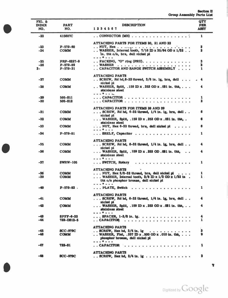
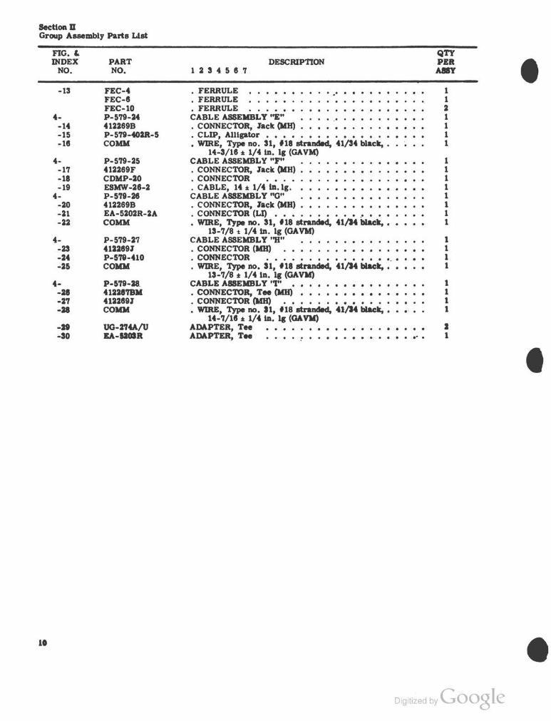
...... GNup ,......., Puta Lilt
• IBC'l'ION D
GROUP .ABBI:IIBLY PARTB LJBT
no.• Qft DfDBX PART , DB8CRIP'l'IOM PD
MO. MO. 1114117 ~
1- P-l'lt TBSTD, FUEL QUAM'rrrY GAGE - TYPE IID-1 .., -1 P-l'lt-11 • PANEL AND CABINET .AS8BMBI.Y . . . . ... 1
(Bee ftpre S for bnakdowD) ~-
ATl'ACBING PARTB -I COIOI • SCREW, Rd bd, 1/4-· tau.d, 1-JA-ta. 11. bl'a, daU 4
Dickel p1 -1 COIOI • WASHER, SpUt, 0. J'll m ll 0. 481 OD ll 0. M7 Ia. t111r, llalaleu
at.eel 4
---•---1- P-l'lt-11 • TRANSIT CASE A88EIIBL Y • • • • • q, • • • . . 1 .... P-l'lt-10 •• PLA.TB, .......... . . . . 1
ATl'ACBING PARTB -I COMM • • SCREW, Rd bd, 4-40 tau.d, l/4 Ia. 11. lin, daU ldclatl • I
p1 .. COIOI •• WASHER, I'Dtei'Ml tooaa, .110m ll 7/U OD ll 1/11 Ia. I
• tblt o/a, pboepbor broue, daU alckel Ill -7 COIOI •• NUT, Ba, 4-40 tau.d, lin, daU Dickel Ill I ---•----1 P-l'lt-11 •• PLA-TE, W&I'DIDI • • • • • • • • • • • • • • • 1
• ATTACBING PARTB -I COIOI • • SCREW, Rd bd, 4-40 tau.d, 1/4 ta. 11. lin, daU I
Dickel p1 -10 COMM • • WA8BER, IDtei'Ml tooaa, . 1JO m a 7/U OD a 1/IJ Ia tbk • I
o/a, pboaJJbor broue, daU alc:IDil Ill I -11 COIOI • • NUT, Ba, 4-40 tau.d, bn, daU alc:kel Ill . . . . . ---•--- .
-11 P-171-n • • CHART, CorncUoa • • • • • • • • • • • • 1 -11 J'B8-111.A • • F()()'l' •· • • • • • • • • • • • • • • • • • •
ATTACBING PARTB -14 COMM • • SCREW, BIDdlq bd, 10-11 tau.d, 1/8 Ia. 11. bl'a, • • • -11 101-01
da11 alckel Ill • • NUT' a.a (BN) • • • • • • • • . . . . • ---•---
-11 110PBL-t • • INBULA TOR, V1bratlaD (LO) • • .. ATTACBING PARTB
-17 CCIIII . • • SCREW, Rd bd, 10-11 tau.d, 1/11 Ia. 11. lin, dlll1 • 11 lllcDl p1
-18 COIOI •• WASBER, SpUt, .Ill ma .111 ODa .otO ta. t111r, 11 ........... -11 COIOI • • JnJT, Ba, 1o-IJ tau.d, ..... ddllllclall Ill . . . . 11 ---•----10 P-l'lt-11 . • w A8IIBR, Plat • • .. -11 P-l'lt-lt • • Lilli:, GI'OUDII . . . . . , -II MMM •• FABTBNBR (UL). . . . . . I
ATl'ACIIING PARTB -a COIIII •• SCREW, Plat bd, 1-U ~ 1/11 Ia. 11. lin, daU • 10
lllciDil Ill -a.. COIIII • • WASBBR, 8pUt, .111 m • • 1a OD • • •1 ... -. . • • 10 ......... .e-1
• a
Digitized bvGoogle

~:M:tiOD D \lroup Auembly Parta Ltlll
• "' "'
_fj??_\\ .If) "'"'
I
... I g ! I I ! I • f"
I
!
I .. I I
I I
j
4 • Digitized by Coogle

•
•
•
FIG. 6 INDEX
NO.
-II
-II -2'1 -18
-It
-10
-Sl -SJ
-U
ss-
-1
-2
-s -" a-
-I
-· _.,
-· -· ·10
-11
-12
-13 -14
·II ·11
·1'1 ·11
-It
-JO ·11
PART NO.
COM II
P-1'18-'JI P-1'18-'11 FBS-888
RIT-1311
IU-4-R IU-4-L
RIT-MI COIOI
P·l'll-81
P-1'19-SI P-1'19·10
COMII
COMII
232'74 P-l'll-'14 P·l'lt-SI
COMII
DB-JD IPDII-4, .110 COMII
B'UMC-11. 1/* sco-tt
COIOI
COMII
PRP-GJ'l-1 COMII
IPDM-1, 1/11 COMII
PRP-IU'l-1 ZIDIU-S
liS-&11'1
• • NUT, Hex, l-SI tbNad, bra, da11 Ideal pl • • ---•---• • RUBBER, 8poDp • • • • RUBBER, 8poDp • • • FOOT, Bumper • . • •
A TTACIIING PARTS •• RIVET, Tubalar, '1/llta Ia ----~ ---•• SUPPORT, Ltd • • • • • • SUPPORT, Lid • • • •
ATTACHING PARTS •• RIVET, Tubalar, 1/11·ta. Ia • • • • • • . . . . . • • • WASHER, Flat, .110 m • . I'll OD • • au ta. tbt, bra,
da11 Ideal p1 ---•---• • TRAN8IT CABB AND COVER AaRMBLY • • • • • • •
PANEL AND CABINET AIAIIBLY • PANEL .. EIIBLY • • • • • • •
ATTACHING PARTI • SCREW, Rd bd, lD-SJ tbNad, 1/* Ia. Ia· bra, da11 •
Ideal p1 • WASIIER, Split, . lli.ID • .SJI OD • . oto Ia. tb1r, • • •
Dlaleu.a.el ·--•---•• PLUG, Protect (CB) .. . . •• PACKING, ''0" riDe •••••• • • KNOB ASQMBLY • • • • •
ATTACHING PARTS ••• SCREW, let ---•---••• KtiOB ••••• . . . . . . .
. .
••• IPACBR • • • • • • • • • • • • • • ••• SCREW, Blaclbll bd, t-40 tbNad, 1/lla. lr, tbnM
cutUDc, ............ • • B'UBHING • • • • • • COLLA.R • • • •
ATTACHING PARTI • • II':RBW, let ---•--- . . . . .. . . • • WAIHBR, Flat, • U'l 1D • .100 ID • • 010 ta. tbt, • • • pbo.....,.. ...... • • PACKING, ''0" riDe (PRO). • • • • • • • • • • • •• ICRBW, . Blaclbll bd, 1-IJ tbnU, S/* ta. lr, bra, •
dallldckal .. •• IPACBR • • • • • • • •• ~ • • • • • • • • • • • .• wAIDR, Flat, .uo m • .ua oo • . au ta • ..., bra,
da11 Ideal pl •• PACmfG, ''0" riDe (PRO) •. DIOB •••. • ••
ATTACIIDIG PARTI . • .:R.BW' llet • • • • • • • • • • • ---. ---• • CONN'EC1'01l (1111) • • • • • • • • • • • • . . c~ (1111) ; • • • • •. • •. • • •
. . .
•
QTY PD ,..., 10
J J J
J
1 1
4 4
1
.., 1
10
10
1 1 1
J
1 1 1
1 1
I
1
1 I
I I
I I
t
1 ·1
Digitized bvGoogle
I

Sectloo D Group Auembly Parts Lta
•
;;. :a a I II < .. j .. tJ
! J
I • c ~
I 0 ... • l 1':
• • Digitized by Coogle
•
•
•
FIG. 6 INDO
NO.
-22
-23 -24
-25 -28
3-
-2'l
-28
-21 -so
-31
-32
-33
-M
-35
-se
-3'l
-sa -3t
-4'1
PART NO.
41580'JC
P-S'lt-80 COIOI
PRP-G2'J-t P-57t-8t P-S'lt-31
COIOI
COMM
505-811 505-812
COIOI
COMM
COMM
P-571-81
COMM
COIOI
SWRW-105
COIOI COMM
P-S'rt-82 •
COIOI
~010(
SPFF-8-SI 'JU-.. 11-1
ICC·t'IIC COIOI
'IJI-81
ICC-t'IIC
DESCRIPTION 1 2 3 4 5 8 'l
• • CONNECTOR (MH) • • • • • . . . . . . . . . . . . ATTACHING PARTS FOR ITEMS 20, 21 AND 22 : : ;,:a::: h.t~~ tdb; 1ii8 ilix s5ia4 ob.; ~~i : :
ln. thk o/a, brs, dull nickel p1 ---•---•• PACKING, "0" ring (PRtJ). • • • • • •••• • • WA811ER • • • • • • • • • • • • • • • • • •• CAPACITOR AND IJANGE SWITCH ASSEMBLY
ATTACHING PARTS • • SCREW, Rd hd, 1-32 thread, 3/8 ln. ls, bra, 41U
nickel pl •• WASHER, Split, .15t m x • 253 OD x • 011 ba. thk, • • •
atalnh!ss steel ---.-- -· • • • CAPa\CI'I'OR • • • • " • • • • • • • • • • • • CAPACI'I'OR • • • • • • • • •. • • • • • • • • •
ATTACHING PARTS FOR ITDIS 28 AND 2t ••• SCREW, Rd hd, 8-32 Ulnad. 1/4 ln. ls, bra, clll11 ••
nickel pl ••• WASHER, Split, .lit m X .253 ODx .011 ba. tl*, •
stainless steel · ••• NUT, Hex 8-32 thread, bra, cllllllllclllll p1 ---•---••• SHELF, Capacitor • • • • • •••••••
ATTACHING PARTS ••• SCREW, Rd hd, 1·32 thread, 1/4 ln. Jr. bra, clll11 • •
nickel p1 ••• WASHER, Spllt, .lit m x .ISS OD •• 1 ba. thk,
atatnleas steel ---•---• • • SWITCH, Rolar)' • • • • • • • • • • • •
ATTACHING PARTS ••• NUT, Hex 31*-32 tbnad, bra, clll11 n1ciDil Ill . • • • • WASHER, lntemal tooth, l/8 m x 1/2 OD a 1/h Ia •
thk o/a phosphor broiUie, clll11 nic•l p1 ---•---• • • PLA. TE, 8wltcb • • • • • • • • • • • • • • • • •
ATTACHING PARTS ••• SCREW, Rd hd, 1-32 Ulnad. 1/41D. Jr. bra, clll11 ••
nickel pl ••• WASHER, 8pUt, .lit m x .253 OD x •• liD. tl*, ••
ltalDleNIIteel ---•---••• SPACER, 1-3/* ln. lc. • • CAPACI'TOIJ • • • • • •
A'ft'ACIIING PARTS • • SCREW, lla hd, 3/4 Ill. 1c • • • • • • • • • •
. • • WASBER, Flat, .257m x .100 0D a .010 Ia. tlllr, • plio ........... clll11 alcke1 Ill ---•---
• • CAPACITOR
A'ft'ACIIING PARTS • • ICREW, Sa hd, I/41D. lc • • •
QTY PBR
ltBft
1
• • 3 I 1
.. 4
1 2
I
I
I
1
1
1 1 ·
1
.. 4
4 1
• • • •
Digitized by Google

SecUOD D Group Assembly Parts List
i
no·. 11 DmEX
NO.
-49
-50 -51 -52
-53
-54
-55 -58 -57 -58
-59
-eo ·81 -82
-U
-84
-85 -88 -87 -II -88 -70
·-1 -2 -s
4--4 -5 -8
4--7
-· -8
4-·10 -11 -12 ·lS
PART NO.
COMM
SPC-27 PRP-8227-5 722-606
COMM
COMM
PRP-8227-1 722-SS 722-824 722-77
COMM
722-822
'722-710 P-579·8·
COMM
c(IIO(
PRP-8227-1 P-578-81 'P-578-73 P-5'18-100 P-5'18-70 P-5?8-lOS
P-5'11-20 .122888 • 1228'1'1' COIDI
P-578-21 .1JI88R 41221'1L EIDIW-18-Z P-5'19-22 41228811 41228'iEK COMM
P-S'II-23 412288F P-5'18-401R-11 P-5'18-4018-lS .ESIIW-18-2 COIDI
FEC-1
DESCRJPnON 1 2 3 4 5 6 7
• • WASHER, Flat, . 25'1 m x . 500 OD z . 010 ln. thk, phosphor bronze dull nickel pl
---•---•. SPACER, 5/16 ln. lg ~ 1 • . PACKING, "0" ring (PRU) •• STOP. • • • • •
A.TTACIUNG PARTS •• SCREW, Rd hd, 8/32 thread, 1/2 ln. lg, bra, dull •
nickel pl •• WASHER, Sput, .159m x .253 OD z .OSlin. thk, ••
stainless steel - - -. - - -
.• • PACKING, "0" ring (PRU) • • • • HANDLE, Locking _ • • HUB, Brake . • . . . . • . • • GASKET • • • • • • • • -:, •
ATTACIUNG PARTS SCREW, nat hd, 8-32 thread, '1/18 ln. lg, bra, cWI •• nickelpl
•• RJitfG • • • • • ---. ---• • SEAL, Shaft • • • • • FRAME, Window
ATTACIUNG PARTS •• SCREW, Blndlng head, 8-32 thread, S/8 ln. lg. bra, dull
Dickel pi •• WASHER, Flat, .150 ID z .112 OD z .032 ln. thk, bra,
dull nickel pl ---•---• • PACKING, "0" ring (PRU) • • 'WIN'I:JC:JW • • • • • •• GASKET, Window • •• PANEL ASBEMBLY • GASKET ••••••• • CABINE1' ASSEMBLY
CABLE ASSEMBLY "A" ••••••• , , •••• • CONNECTOR, Ansle (MBJ • • • • • • • • • • • CONNECTOR, Tee (MH) • • • • • • • • • • • • . wmE, TJpe No. Sl, f18 stranded, 41/3. blact,.
7·~7/18 :t 1/2 ln. lg (GA VII) CABLE ASSEMBLY "B" • • • • .. CONNECTOR, Angle (MB) • , • CONNEC~R, Tee (MB) • • • • • CABLE, 78-7/18 :t 1/J Ill. lg CABLE ASSEMBLY "C" ••• • CONNECTOR, Anpl (MH) • • • '. • • • • • · • • • CONNECTOR, Tee (MB) • • • • • • • • • • • • WIRE, Type no. 31, f18 straDdecl, 41/*4 blact, •••. , •
74-7/16 :t: 1/2 ln. lg (GAVII) CABLE ASSEMBLY ''D'' • • • • • • CONNECTOR, lack (UB) • , , • • • CLIP, Alligator • · .• • • • • • • • , • • • • CLIP, Alligator . • • • . • . • • • . • • . . . • • • • CABLE, 14-3/16 :t: 1/4 ln. lg • • • • • • • • • • • , • • WIRE, Type no. 3 1~ f.18 8tiUdld, 41/S4 blact, 4-3/11 *
1/4 ln. lg (GA VM) • FERRULE • • • • • • • • • • • • • • • • • • • ••
QTY P.Elt
ASSY
s
s 8 2
2
2
2 2 2 2
8
2
2 2
• 4
4 I I 1 1 1
1 I 1 l
1 "1 1 1 1 I 1 1
l 1 l 1 1 1
1
Digitized by Google
•
•
•

•
•
I I
I I 1 • i u
0 1 ~
u . • i
•
Digitized by Coogle
Sec:Uon D Group ABSembly Parts Llst
10
nG.& INDEX
NO.
-13
4--14 -15 -18
4--17 -18 -19
4--20 -21 -22
4--23 -24 -25
4--2. -2'f -28
-II -30
PART NO.
FEC-4 FEC-8 FEC-10 P-579-24 412269B P-5'79-402R-5 COMM
P-5'f9-25 412269F CDMP-20 ESMW-28-2 P-579-26 412269B EA-5202R-2A COMM
P-579-27 4122891 P-5'78-410 COMM
P-5'79-28. 41221'7811 412289J COIDI
UG-2'f4A/U EA-UOIR
DESCRIP'nON 1 2 3 4 5 8 7
• FERRULE .. · . . . . • FERRULE • FERRULE ••••••• CABLE ASSEMBLY ''E" . . • CONNECTOR, Jack (MH) • • • • • • • CLIP, Alligator • • • • • • • • • • • •• • WIRE, Type no. 31, 118 stranded, 41/34 black, •
14-3/18 :t 1/4 ln. lg (GAVM} CABLE ASSEMBLY "F" • CONNECTOR, Jack (MH) ••• . CONNECTOR • • • • • . CABLE, 14 :t 1/4 ID.lg. • CABLE ASSEMBLY "G" • CONNECTOR, Jack (MH) • • • • • • • • . CONNECTOR (LJ) • , • • • • • • • • .• • • • • • WIRE, Type no. 31, 118 stranded, 41/M black, •
13-7/8 t 1/4 ln. lg (GA VM) CABLE ASSEMBLY "H" , ••••••• , • • CONNECTOR (MH) • • • • • • , • • • • • . CONNECTOR ••.••••••••••••.• • WIRE, Type no. 31, 118 stranded, 41/M black, ••
13-7/8 :t 1/4 ID. 1J (GAVM) CABLE ASSEMBLY "I" • , • , • • • • • • • • • • CONNECTOR, Tee (MH) • • • • • • • • • • • • • • CO~ECTOR (MH) • • • • • • • • • • • • , • WIRE, Type no. 11, 118 stranded, 41/M black, •
14-7/18 :t 1/4 ln. 1J (GAVII) ADAPTER, Tee . .. . . . . . . . . ADAPTER, Tee ...
QTY PER A8IY
1 1 2 1 1 1 1
1 1 1 1 1 1 1 1
1 1 1 l
1 1 1 1
2 1
Digitized by Coogle
•
•
•

• IICTIOHM
CLAII CODB OR STOCK NO PART SOURCE CODE no." QTY \IICRO INDEX PER FILM
AF NAVY . NtiMBER AF NAVY NO. AR'nCLE INDEX
BUMC-13, 5/8 S-8 1 CABLE 4-13 1 CDMP-20 4-11 1 EA-5202R-2A 4-21 1 EA-5103R •-so 1 ESIIW-18-2 4-8 a
4-11 4-18
FEC-I 4-11 1 FEC-10 4-d a FEC-4 4-d 1 FEC-8 4-11 1. FEB-liSA 2-la • FEB-188 2-· 2 KNB-ID a-a I NUT 2-1 • 2-11 NUT 2-11 11 NUT 2-25 18
a-a NUT a-ae I
• P-511 2- Ref P-511-100 a-• 1 P-511-101 S-10 I P•511-10 ·- 1 P-5:J;·21 ·- 1 P-1 -II 4- 1 P-111-11 4- 1 P-511-24 (- 1 P-511-25 4- 1 P-&1t-ae 4- I P-511-21 ·- 1 P-l'lt-. 4- 1 P-111-21 2-11 1 P-5'lt-SO a- 1 P·5'lt-a1 ·- 1 P-l'lt-SI 1- 1 P-111-11 1-1 I
a-P-511-H a- 1 P-l'lt-4018-11 4-tt I P-511-WR-11 4-11 1 P·51t-402R-1 4.:11 1 P-511-410 4-24 1 P·l'lt-80 a-ll I P·5'lt-10 a-n 1 P-l'lt-'ll a-e'l I P-511-14 a-4 1 P-5'11-15 2-18 I P-5'lt-'l8 1-2'1 2 p. I'll-'1'1 2-d 1 P-l'lt-11 1-M 1 P·l'lt-12 1-40 1 P-l'lt-M t.e2 2 P-l'lt-M a-a 1
11
Digitized by Coogle

s.cttoa m Numertcallnda
c'LAss CODE OR STOCK NO.
AF NAVY
-
PART SOURCE CODE
NUMBER AF NAVY
P-5'78-89 P-5'79-90 P-5'79-81 P-5'78-92 P-5'78-93 PRP-822'7-1
PRP-G2'J-5
PRP-G2'J-8 Rrr-1351 Rrr-889 SCC-t'l8C
SCREW SCREW
SCREW
SCREW SCREW SCREW
SCREW SCREW
scuw
scan SCREW ICUW IPD-t'l IPDII·4,.IJO IPIJII-1, 1/11 IFIW-1-11 IV ... •L .., ...... ....... ~ w . .... • AIUII
-~
-~ ...... WA8D W.AIBR WID
FIG. Ia QTY MICRO INDEX PER FILII
NO. AR11CLE INDEX • 3-28 s 2-4 1 3-88 z 2-20 4 2-8 1 S-1'J 8 1-55 3~85 1-13 'J S-51 S-25 s 2-28 2 2-Sl 4 1-45 8 S-48 z-z 4 Z-5 4 2-8 2-14 28 S-1 2-l'J 18 2-11 10 1-5 • S-11 ,_.18 S-8 1 1-14 8 S-Z'J S-11 14 1-15 S-41 s-u I 1-H • a-as 4 • 1·10 I .. , l ·-11 l 1-tl 4 t-ao I J...to ' ...., • ... • .... • .... .. t: .. ... ~ .. .. t: ..... .... :::: • ..... ~ a.u • ... .... ._ .. • 1r ' •
• Digitized bvGoogle

I rf CLASS CODE OR STOCK NO. PART SOURCE CODi:
AF NAVY NUMBER AF NAVY
WIRE WIRE
WIRE 044454 150PHL-d 2ENU 232'74 SC0-19 4122881-: 412288M 412288R 412287BM 412287EK 412267L 412287T 4122898
412289F I 4122891
I 412298F 415807A
I 4158078
! 415807C I 505-811 l 505-512
722-DS12-5 722-51 722-38
• 722-808 722-710 722-77 722-822 722-824 MM-02
•
na. & INDEX
NO.
4-18 4-22 4-25 4-28 2-22 2-18 S-18 s-s S-10 4-1 4-7 4-4 4-28 4-8 4-5 4-2 4-14 4-20 4-17 4-23 4-27 4-10 s-ao S-21 S-22 S-29 S-SO S-44 S-47 S-58 S-52 S-81
·S-58 S-80 S-57 2-15
SeetlOil m Numerical Inda
QTY MICRO PER nLM
ARTICLE INDEX
1 2
1 2 4 2 1 1 1 1 1 1 1 1 1 2
1 2
1 1 1 1 1 2 1 1 2 2 2 2 2 2 8
IJ
Digitized by Coogle

•
•
• Digitized by Coogle


( PIN : 01718~