Embed Size (px)
Citation preview
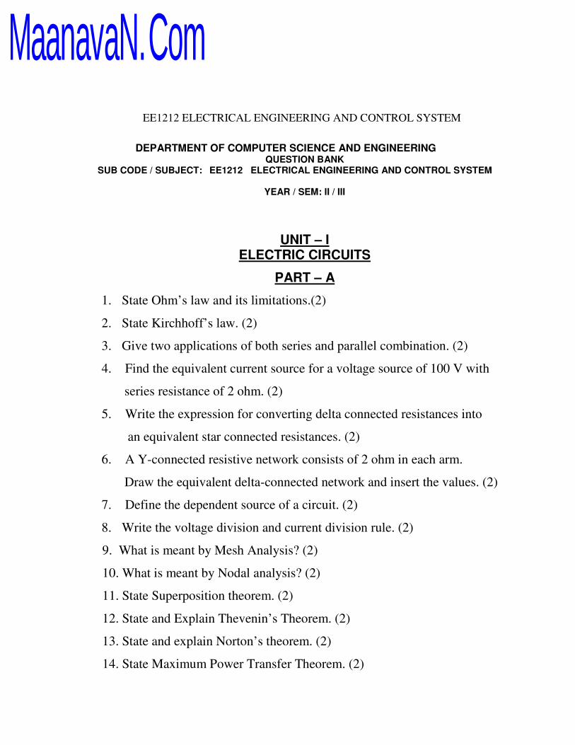
EE1212 ELECTRICAL ENGINEERING AND CONTROL SYSTEM
DEPARTMENT OF COMPUTER SCIENCE AND ENGINEERING
QUESTION BANK
SUB CODE / SUBJECT: EE1212 ELECTRICAL ENGINEERING AND CONTROL SYSTEM
YEAR / SEM: II / III
UNIT – I
ELECTRIC CIRCUITS
PART – A
1. State Ohm’s law and its limitations.(2)
2. State Kirchhoff’s law. (2)
3. Give two applications of both series and parallel combination. (2)
4. Find the equivalent current source for a voltage source of 100 V with
series resistance of 2 ohm. (2)
5. Write the expression for converting delta connected resistances into
an equivalent star connected resistances. (2)
6. A Y-connected resistive network consists of 2 ohm in each arm.
Draw the equivalent delta-connected network and insert the values. (2)
7. Define the dependent source of a circuit. (2)
8. Write the voltage division and current division rule. (2)
9. What is meant by Mesh Analysis? (2)
10. What is meant by Nodal analysis? (2)
11. State Superposition theorem. (2)
12. State and Explain Thevenin’s Theorem. (2)
13. State and explain Norton’s theorem. (2)
14. State Maximum Power Transfer Theorem. (2)
MaanavaN.Com

EE1212 ELECTRICAL ENGINEERING AND CONTROL SYSTEM
PART – B
1. Find the node voltages V1 and V2. (16)
2. Find the current through R2 and R3 using mesh analysis. (16)
3. Find the voltage across R3 using Nodal analysis. (16)
MaanavaN.Com

EE1212 ELECTRICAL ENGINEERING AND CONTROL SYSTEM
4. Find the current labeled "I" using both mesh analysis. (16)
5. Determine Thevenin’s equivalent across the terminals AB for the circuit shown
in figure below. (16)
MaanavaN.Com

EE1212 ELECTRICAL ENGINEERING AND CONTROL SYSTEM
6. Find the value of RL so that maximum power is delivered to the load
resistance shown in figure. (16)
7. Using superposition theorem find the current in 10 ohm resistor of the network
shown below. (16)
8. Find the current in each resistor using superposition principle of figure. (16)
MaanavaN.Com

EE1212 ELECTRICAL ENGINEERING AND CONTROL SYSTEM
9. Solve for current in 5 ohm resistor by the principle of superposition
theorem. (16)
10. i) State and explain maximum power transfer theorem for variable pure
resistive load. (8)
ii) Using Norton’s theorem, find current through 6 ohm resistance shown in
figure. (8)
11. Find the value of RL for maximum power transfer in the circuit of figure. Find the
maximum power. (16)
MaanavaN.Com

EE1212 ELECTRICAL ENGINEERING AND CONTROL SYSTEM
12. Find the Thevenins’s equivalent circuit of the circuit shown below, to left
of the terminals ab. Then find the current through RL = 16 ohm and 36 ohm.
(16)
UNIT – II
SINUSOIDAL STEADY STATE ANALYSIS
PART – A
1. Define R.M.S value.(2)
2. For purely capacitive circuit, excited by sinusoidal voltage, find the phase
relation between applied voltage and current. (2)
3. How are the following affected by change of frequency?
a. Resistance b. Inductive reactance c. capacitive reactance (2)
4. Give the relation between apparent power, average power and reactive
power. (2)
5. What is an impedance triangle? (2)
6. What is voltage triangle for a RLC series circuit? (2)
7. What is P.F and what is reactive power? (2)
8. Define quality factor of series resonant circuit. (2)
9. What is resonance? (2)
MaanavaN.Com

EE1212 ELECTRICAL ENGINEERING AND CONTROL SYSTEM
10. Write the relations between phase and line values in a delta and star
connected loads. (2)
11. Write the expressions for the power factor in a balanced three phase circuit. (2)
12. What do you understand by series and parallel resonance? (2)
13. A voltage of v (t) = 100 sinωt is applied to a circuit. The current flowing
through the circuit is i(t) = 15 sin (ωt-30). Determine the average power
delivered to the circuit. (2)
14. Derive resonant frequency for series RLC circuit. (2)
15. Give the relation between Vph and VL, Iph and IL for a star circuit. (2)
16. Draw the phasor diagram of RC series circuit. (2)
17. Find the impedance offered to the source by the load. (2)
18. State the condition for resonance in RLC series circuit. (2)
19. A resistance 5 ohms, inductance 0.02H and capacitor 5 microfarads are
connected in series. Find the resonance frequency and the power factor at
resonance. (2)
20. Two capacitances C1 and C2 of values 10µF and 5µF are connected in
series. What is the equivalent capacitance of this combination? (2)
MaanavaN.Com

EE1212 ELECTRICAL ENGINEERING AND CONTROL SYSTEM
KINGS COLLEGE OF ENGINEERING 8
PART – B
1. An alternating voltage is given by V = 311 sin314t and the current is i = 707
sin 377t. calculate i) frequency ii) maximum value. iii) effective value
iv) average value v) form factor. vi) peak factor (16)
2. (i) A Pure resistor, a pure capacitor and a pure inductor are connected in
parallel across a 50Hz supply, find the impedance of the circuit as seen by
the supply. Also find the resonant frequency(8)
(ii) When connected to a 230V, 50Hz single phase supply, a coil takes
10kVA and 8kVAR. For this coil calculate resistance, inductance of coil and
power consumed. (8)
3. (i) Determine the equivalent impedance. (8)
(ii) Determine the total impedance, current, phase angle and the voltage
across each element. (8)
MaanavaN.Com

EE1212 ELECTRICAL ENGINEERING AND CONTROL SYSTEM
4. (i) A Circuit having resistance 12 ohms, an inductance of 0.15H and a
capacitor 100 microfarad are connected in series across 100V, 50Hz supply.
Calculate a) impedance b) the current c) power factor (8)
(ii) A symmetrical three phase 400V system supplies a balanced delta
connected load. The current in each branch circuit is 20A and phase angle
40° (lag) calculate the line current and total power. (8)
5. A coil of resistance 5 ohm and inductance 100 mH is connected in series
with a 200 microfarad capacitor across a 220V, 50Hz supply. Calculate (i)
inductive reactance, (ii) capacitive reactance, (iii) impedance of the whole
circuit in complex form (iv) the current (v) power factor (vi) total power and
(vii) the voltages across the coil and the capacitor. Draw an illustrative
phasor diagram depicting the voltage and current. (16)
6. (i) In an RLC series circuit if ω1 and ω2 are two frequencies at which the
magnitude of the current is the same and if ωr is the resonant frequency,
prove that ω2
r = ω1ω2. (8)
(ii) A series RLC circuit has Q = 75 and a pass band (between half power
frequencies) of 160 Hz. Calculate the resonant frequency and the upper and
lower frequencies of the pass band. (8)
MaanavaN.Com

EE1212 ELECTRICAL ENGINEERING AND CONTROL SYSTEM
7. (i) A balanced three phase star connected load with impedance 8+j6 ohm per
phase is connected across a symmetrical 400V three phase 50Hz supply.
Determine the line current, power factor of the load and total power. (8)
(ii) An alternating current is expressed as i=14.14 sin 314t. Determine rms
current, frequency and instantaneous current hence t =0.02ms. (8)
8. (i) Determine the equivalent impedance across AC. (8)
(ii) What is power triangle and impedance triangle for RL circuit? What is
the power factor? (8)
9. (i) A balanced star connected load of 4+j3 ohm per phase is connected to a
400V, 3 phase, 50Hz supply. Find the line current, power factor ,power,
reactive volt ampere and total volt ampere. (8)
(ii) A Voltage source 100V with resistance of 10 ohms and inductance 50
mH, a capacitor 50 microfarad are connected in series. Calculate the
impedance when the frequency is (i) 50HZ (ii) 500Hz (iii) the power factor
at 100Hz. (8)
MaanavaN.Com

EE1212 ELECTRICAL ENGINEERING AND CONTROL SYSTEM
UNIT – 3
DC MACHINES AND TRANSFORMERS
PART – A
1. What is the basic principle of dc generator?(2)
2. State the purpose of the magnetic yoke in dc generator? (2)
3. How do you reduce the hysteresis loss in armature? (2)
4. What is the main function of commutator and brush? (2)
5. Write the expression for induced emf and Name the different types of dc
generator? (2)
6. A 4 –pole wave wound generator having 40 slots and 10 conductors placed
per slot .the flux per pole is 0.02wb.calculate the generated emf when the
generator is driven at 1200 rpm. (2)
7. Draw the circuit model of a dc shunt generator and write the relationship
among the current and voltages? (2)
8. What is the basic principle of dc motor? (2)
9. List out the important parts of dc motor? (2)
10. What is the nature of the current flowing in the armature conductors of the dc
motor? (2)
11. Give the significance of back emf in dc motor? (2)
12. Sketch the armature current – torque characteristics of dc shunt motor? (2)
13. Draw the torque –current characteristics of dc series motor(2)
14. Why series motor cannot be started without load? (2)
15. List out the applications of dc shunt motor(2)
16. What are the different method of speed control of dc motor? (2)
17. Define regulation and efficiency of a transformer. (2)
18. Define the transformer. (2)
MaanavaN.Com

EE1212 ELECTRICAL ENGINEERING AND CONTROL SYSTEM
19. How can the eddy current loss be reduced in the transformer? (2)
20. Draw the no-load vector diagram of a transformer. (2)
21. What are the turns ratio and transformer ratio of transformer? (2)
22. List out the different types of losses in a transformer. (2)
23. What are the necessary tests to determine the equivalent circuit of a
transformer? (2)
24. Draw the exact equivalent circuit of a transformer. (2)
25. The primary and secondary voltages of a 25kva power transformer are 2200v
and 220v respectively. The transformer has 56 turns in the secondary.
Calculate the number turns in the primary. (2)
PART-B
1. Explain the operation and principle of a dc generator, with neat sketch.(16)
2. Explain the different types of dc generator characteristics. (16)
3. Derive the EMF equations of dc generator and transformer. (16)
4. A 4 pole shunt generator, with a lap wound armature has field resistance of
50ohm armature circuit resistance of 0.1ohm. The generator is supplying
sixty 100v, 40w lamps. Find the total armature current in each armature
conductor and generated EMF. The brush contact drop is 1v brush. (16)
5. Explain the characteristics of dc motor and derive the torque equation of dc
motor frame first principle. (16)
MaanavaN.Com

EE1212 ELECTRICAL ENGINEERING AND CONTROL SYSTEM
6. Explain the different types speed control of dc motor. (16)
7. A 250v dc shunt motor takes 41a at full load resistance of motor armature
and shunt field windings are 0.1 ohm and 250 ohm respectively. Find the
back EMF on full load. (16)
8. A 230 v dc shunt motor takes an armature current of 20a on a particular
load. The armature circuit resistance is 0.5ohm .find the resistance required
in series with armature to reduce the speed by 50%, if the torque is constant.
(16)
9. An 220v dc shunt motor with an armature resistance of 0.5 ohm is excited to
give constant field .at full load, the speed is 500 rpm and armature current is
30a.if a resistance 1 ohm is connected in series with the armature ,find the
speed at full load torque. (16)
10. A 230v dc shunt motor takes an armature current of 6a from 230v mains at
no load and runs at 1200 rpm. The armature resistance is 0.2ohm.
Determine the speed and torque developed by the motor with 37A armature
current and the same flux. (16)
11. A 2000/200 v,20 KVA transformer has a primary winding resistance of 2.5
ohm and a secondary winding resistance of 0.06ohm.determine the primary
MaanavaN.Com

EE1212 ELECTRICAL ENGINEERING AND CONTROL SYSTEM
and secondary currents at rated load, the total winding resistance referred to
primary ,and the total winding resistance referred to secondary (16)
12. A 50 KVA, 2200/220v transformer when test gave the following results.
Oc test, measurements on LV side :405w,5a,220v
Sc test ,measurement on HV side:805w,20.2a,95v
Find the approximate equivalent circuit model of the transformer. (16)
13. Explain with neat diagram the operation of sumpner’s test. (16)
14. A 10 KVA ,200/400v,50 Hz single phase transformer gave the
following test results
Open circuit test (hv winding open )200 v ,1.3a 120w
Short circuit test (lv winding short circuited) 22v 30a,200w
Calculate (1) magnetizing current and current corresponding to core loss at
normal voltage and frequency.(2) parameters of equivalent circuits as
referred to low voltage winding. (16)
15. The oc and sc tests on a kva ,200/400v ,50hz single phase transformer gave
the following results:
Oc test on lv side :200v,1a,100w
Sc test with lv side shorted :15v,10a,85w
Determine the parameters of the equivalent circuit and draw the equivalent
circuit referred to the LV side. (16)
MaanavaN.Com

EE1212 ELECTRICAL ENGINEERING AND CONTROL SYSTEM
UNIT – 4
AC MACHINES
PART – A
1. What is synchronous machines?(2)
2. List the difference between salient pole and cylindrical type of rotor?(2)
3. Define voltage regulation. (2)
4. What is meant by OC and SC test? (2)
5. What are the advantages of three phase induction motors? (2)
6. What are the two main parts of an induction motor? (2)
7. What is meant by end ring? (2)
8. A synchronous generator has 9 slots per pole. If each coil spans 8 slot
pitches, what is the value of the pitch factor? (2)
9. The squirrel cage rotor is also known as short circuited rotor. Why? (2)
10. Compare squirrel cage rotor and slip ring rotor. (2)
11. Define slip speed and slip. (2)
12. What is frequency of rotor EMF? (2)
13. Write down the torque equation of three phase induction motor. (2)
14. Give the equation for maximum starting torque. (2)
15. How do you reverse the direction of the rotation of the three phase
induction motor? (2)
16. What are the different types of induction motor starters? (2)
17. What are the advantages and disadvantages of slip – ring induction motor
over squirrel cage motor? (2)
MaanavaN.Com

EE1212 ELECTRICAL ENGINEERING AND CONTROL SYSTEM
18. Why the starters are used for the starting of an induction motor? (2)
19. Single phase induction motor is not self starting motor. Why? (2)
20. What is meant by starting and main winding? (2)
21. What are the characteristics of shaded pole motor? (2)
22. Mention the disadvantages of slip ring induction motor. (2)
23. Define synchronous reactance. (2)
24. Give the expression for the EMF induced in an alternator. (2)
25. State the two types of 3 phase induction motor. (2)
PART – B
1. Explain the principle of operation three phase induction motor.(16)
2. Discuss the starting methods of single phase induction motor. (16)
3. Explain slip-torque characteristics of three phase induction motor. (16)
4. . Explain with neat diagram the following types of single –phase induction
Motor
1) split-phase induction motor
2) capacitor-start induction motor
3) Capacitor run induction motor
4) Capacitor –start capacitor –run motors
5) Shaded –pole motor(16)
7. Explain the different methods of speed control of three phase induction
motor(16)
8. Derive the torque equation of three phase induction motor and Explain the
different types of losses in the induction motor.(16)
9. Why is a single phase induction motor not self starting? Describe
methods of starting of single phase induction motor.(16)
MaanavaN.Com

EE1212 ELECTRICAL ENGINEERING AND CONTROL SYSTEM
10. A 3phase, 50 Hz, star connected 2000 KVA, 2300V alternator gave a short
circuit current of 600A for a certain field excitation. With the same excitation,
the AC voltage was 900V .the resistance between a pair of terminals was 0.12
Ω. Find the full load regulation at i) unity pf ii) 0.8pf lagging.(16)
11. A 3phase, 12 pole star connected alternator has 72 slots and 6 conductors per
slot. If it is driven at 500 rpm, calculate the induced EMF. Assume coil span as
150 deg electrical and flux per pole 40mwb.(16)
12. A 500 KVA,3.3KV,3-phase,star connected alternator is found to give a short
circuit current of 290 A at normal field current. Its effective winding resistance
per phase is 0.7Ω. Estimate the full load voltage regulation for i) 0.8 pf lagging
and ii) unity pf.(16)
UNIT – V
CONTROL SYSTEM
PART – A
1. What is system?(2)
2. What is control system? (2)
3. What are the two major types of control systems? (2)
4. Define open loop and closed loop systems. (2)
5. What is feedback? What type of feed back is employed in control system? (2)
6. Why negative feedback is preferred in control systems? (2)
7. Distinguish between open loop and closed loop systems(2)
8. What is time variant and Time invariant? (2)
9. Define transfer function. (2)
MaanavaN.Com

EE1212 ELECTRICAL ENGINEERING AND CONTROL SYSTEM
10. Write force balance equation of ideal spring, ideal mass. (2)
11. Name the two types of electrical analogous for mechanical system. (2)
12. What is mathematical model? (2)
13. Define unit pulse and impulse response. (2)
14. What are advantages of open loop system? (2)
15. What are the advantages of closed loop systems? (2)
16. What are the applications of DC and AC servo motor? (2)
17. Mention some of the advantages of stepper motors? (2)
18. What are the components of feedback control system? (2)
19. What are the basic elements used for modeling mechanical
Translational system? (2)
20. Give some examples for test input signals? (2)
21. What is an impulse signal? (2)
22. What is an order of a system? (2)
23. Define damping ratio. (2)
24. List the time domain specification. (2)
25. What is step signal? (2)
PART – B
1. Write short notes on :
i) Time response of second order system.(8)
ii) System stability.(8)
2. Write short notes on potentiometer and encoders.(16)
3. Write short notes on :
iii) DC servo motors.(8)
iv) AC servo motors.(8)
MaanavaN.Com

EE1212 ELECTRICAL ENGINEERING AND CONTROL SYSTEM
4. Explain the construction and operation of stepper motors.(16)
5. Explain the time response of second order system.(16)
6. Derive the transfer function for field controlled DC motor.(16)
7. Derive the transfer function for armature controlled DC motor.(16)
8. Explain the time response of first order system.(16)
9. Find the poles and zeros of the transfer function. G(S) = S2
+3S+2 / (S+4)
(S2 +6S+25) and sketch the pole zero plot.(16)
10. When a second order control system is subjected to unit step input the values
t = 0.5 and Wm = 0.6 rad / sec. determine the rise time, peak time, settling
time, and peak over shoot. (16)
MaanavaN.Com