Embed Size (px)
Citation preview
Senior Design Documentation Library Test Plan
Test Plan
Department of Computer Science and Engineering
The University of Texas at Arlington
PAINTeK
Sentinel
Team Members:
Ryan Bell
Eric Cleveland
Sean Pierce
Robert Wunderlich
Late Updated: 6 August 2012 @ 3:15:00 PM
Senior Design Documentation Library Test Plan
6 August 2012 @ 3:15:00 PM i PAINTeK
Table of Contents
Table of Contents ...........................................................................................................................1
List of Figures .................................................................................................................................3
List of Tables ..................................................................................................................................4
1 Introduction ........................................................................................................................1
1.1 Document Overview ........................................................................................................... 1 1.2 Purpose................................................................................................................................ 1 1.3 Scope ................................................................................................................................... 2 1.4 Definitions and Acronyms .................................................................................................. 2
2 References ...........................................................................................................................3
2.1 Overview ............................................................................................................................. 3 2.2 System Requirement Specification ..................................................................................... 3 2.3 Architecture Design Specification ...................................................................................... 6 2.4 Detailed Design Specification........................................................................................... 11
3 Test Items ..........................................................................................................................13
3.1 Overview ........................................................................................................................... 13 3.2 Relational Diagram ........................................................................................................... 14 3.3 Hardware Tests ................................................................................................................. 15 3.4 Unit Tests .......................................................................................................................... 15 3.5 Component Tests .............................................................................................................. 16 3.6 Integration Tests ............................................................................................................... 17
4 Risks ..................................................................................................................................18
4.1 Overview ........................................................................................................................... 18 4.2 Risk Table ......................................................................................................................... 18
5 Features to be Tested .......................................................................................................19
5.1 Customer Requirements .................................................................................................... 19 5.2 Packaging Requirements ................................................................................................... 20 5.3 Performance Requirements ............................................................................................... 20 5.4 Safety Requirements ......................................................................................................... 20 5.5 Maintenance and Support Requirements .......................................................................... 21
6 Features Not to be Tested ................................................................................................22
7 Approach ..........................................................................................................................23
7.1 Overview ........................................................................................................................... 23
Senior Design Documentation Library Test Plan
6 August 2012 @ 3:15:00 PM ii PAINTeK
7.2 Overall Test Strategy ........................................................................................................ 23 7.3 Hardware and Software Configurations ............................................................................ 23 7.4 Testing Metrics ................................................................................................................. 24 7.5 Testing Requirements ....................................................................................................... 24
8 Test Deliverables ..............................................................................................................25
8.1 Overview ........................................................................................................................... 25 8.2 Deliverables ...................................................................................................................... 25
9 Test Schedule ....................................................................................................................27
9.1 Overview ........................................................................................................................... 27 9.2 Test Schedule .................................................................................................................... 27
10 Approvals ...........................................................................................................................28
Senior Design Documentation Library Test Plan
6 August 2012 @ 3:15:00 PM iii PAINTeK
List of Figures
Figure 1-1: Project Sentinel Concept 1
Figure 2-1: Layer Diagram 6
Figure 2-2: Subsystem Diagram 7
Figure 2-3: Module Decomposition Diagram 11
Senior Design Documentation Library Test Plan
6 August 2012 @ 3:15:00 PM iv PAINTeK
List of Tables
Table 2-1: Inter-Subsystem Data Flow ........................................................................................... 8
Table 2-2: Requirements Mapping, Image Processing and Decision Layer ................................... 9
Table 2-3: Requirements Mapping, User Interface and Execution Layer .................................... 10
Table 2-4: Requirements Traceability Matrix ............................................................................... 12
Table 3-1: Relational Diagram ...................................................................................................... 14
Table 3-2: Hardware Tests ............................................................................................................ 15
Table 3-3: Unit Tests .................................................................................................................... 16
Table 3-4: Component Tests ......................................................................................................... 16
Table 3-5: Integration Tests .......................................................................................................... 17
Senior Design Documentation Library
6 August 2012 @ 3:15:00 PM 1 Introduction
1 Introduction
1.1 Document Overview
This document will describe in detail the System Test Plan (STP) for Project Sentinel. The Test
Plan was formulated after completion and review of the Architecture Design (ADS) and Detailed
Design Specifications (DDS) and is intended to verify functionality at each stage of the system
implementation. The following sections will revisit and summarize the critical and high priority
requirements from the System Requirements Specification (SRS), provide an overview of the
ADS and DDS, and will then define the STP laid out by Team PAINTeK. The STP will consist
of Unit, Component/Function, Integration, and System Verification testing.
1.2 Purpose
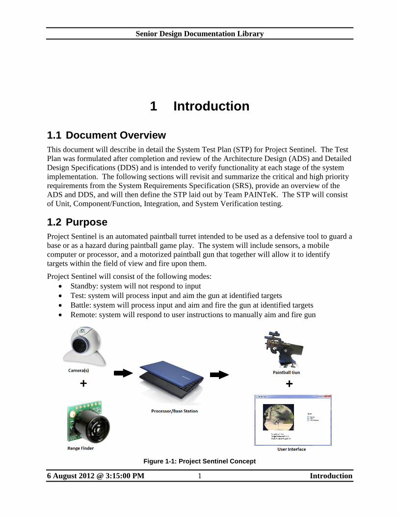
Project Sentinel is an automated paintball turret intended to be used as a defensive tool to guard a
base or as a hazard during paintball game play. The system will include sensors, a mobile
computer or processor, and a motorized paintball gun that together will allow it to identify
targets within the field of view and fire upon them.
Project Sentinel will consist of the following modes:
Standby: system will not respond to input
Test: system will process input and aim the gun at identified targets
Battle: system will process input and aim and fire the gun at identified targets
Remote: system will respond to user instructions to manually aim and fire gun
Figure 1-1: Project Sentinel Concept
Senior Design Documentation Library
6 August 2012 @ 3:15:00 PM 2 Introduction
1.3 Scope
The purpose of project Sentinel is to satisfy the requirements to complete Senior Design I (CSE
4316) and II (CSE 4317) at the University of Texas at Arlington. Team PAINTeK will define,
specify, design, and construct an autonomous paintball gun turret over the course of the Spring
2012 and Summer 2012 semesters. Project Sentinel will allow team PAINTeK to demonstrate
the skills that we have acquired in various classes in a realistic environment. This will cover all
phases of a system design except maintenance, which is excluded because the project will be
considered complete once it has been accepted by the project manager, Mike O’Dell.
Project Sentinel will consist of a turret device that, once deployed, will operate in either standby
or one of three different modes: Test, Battle, or Remote. The system will also include a web
interface that allows an authorized user to change modes and perform other functionality as
described below. While in standby, the turret will not monitor input or produce any output. In
test mode, the turret will monitor input from cameras and/or sensors and will aim the paintball
gun toward any targets that are identified. To indicate Test mode, a green LED will be lit on the
turret. The system will also include a visual output via web interface and a native platform
interface that will show where the system is targeting and other pertinent information such as
distance, shots fired, etc. In Battle mode, the turret will function as it does in Test mode, with
the addition of actually firing at the targets. Finally, in Remote mode, the turret will ignore input
received from its cameras and sensors but will continue to feed this information to its web
interface. The system will allow an authorized user to remotely control where the paintball gun
is aimed and the firing mechanism.
The Spring 2012 semester consisted primarily of defining the project and generating System
Requirements Specification (SRS) and Project Charter documentation. The Summer 2012
semester continued with the Architecture Design Specifications (ADS) and Detailed Design
Specifications (DDS) documents as well as building the actual turret.
1.4 Definitions and Acronyms
ADS: Architecture Design Specification
API: Application Programming Interface
Arduino: An open source prototyping platform with an embedded microcontroller and
additional hardware used for managing peripherals
DDS: Detailed Design Specification
GUI: Graphical User Interface
IP: Internet Protocol
LED: Light Emitting Diode
OS: Operating System
PWM: Pulse Width Modulation
SRS: System Requirements Specification
STP: System Test Plan
TCP: Transmission Control Protocol
UI: User Interface
UDP: Uniform Datagram Protocol
USB: Universal Serial Bus
Senior Design Documentation Library
6 August 2012 @ 3:15:00 PM 3 References
2 References
2.1 Overview
The test plan described in this document stems from the aspects of Project Sentinel that have
been previously described in the Project Charter, SRS, ADS, and DDS. This section includes a
synopsis of these documents for reference when reviewing the STP.
2.2 System Requirement Specification
2.2.1 Customer Requirements
Automated Aiming
Automated Firing
Target Tracking
Standby Mode
Test Mode
Battle Mode
Remote Mode
Base Station
Base Station GUI Initialization
Base Station GUI Shutdown
Base Station Mode Selection
Base Station Durability
Station Portability
Remote Wireless Video Output
Remote Wireless GUI Mode Selection
Remote Wireless GUI Control
Remote Wireless GUI Shutdown
Senior Design Documentation Library
6 August 2012 @ 3:15:00 PM 4 References
2.2.2 Packaging Requirements
Fully Assembled
Preloaded Software
Easily Accessible on a Mobile Device
Base Station Logo
Mobile User Interface Logo
Professional Looking System
2.2.3 Performance Requirements
Quick Response
Outdoor Friendly
Range
Field of View
Battery Life
Must Change Modes Quickly
2.2.4 Safety Requirements
Physical Shutoff Switch
Remote Emergency Shutoff
Non-Lethal
No Exposed Wiring
Clearly Display Mode
Warning Label
Instructions to Switch Modes
Users Must Be Age 16 or Older
Timed Shutoff
No Sharp or Protruding Edges
2.2.5 Maintenance and Support Requirements
Code Documentation
Software Field Maintenance
Hardware Field Maintenance
Senior Design Documentation Library
6 August 2012 @ 3:15:00 PM 5 References
2.2.6 Other Requirements
DC Power
Surrender
Accuracy Feedback
Turret Stability
Documentation in English
Senior Design Documentation Library
6 August 2012 @ 3:15:00 PM 6 References
2.3 Architecture Design Specification
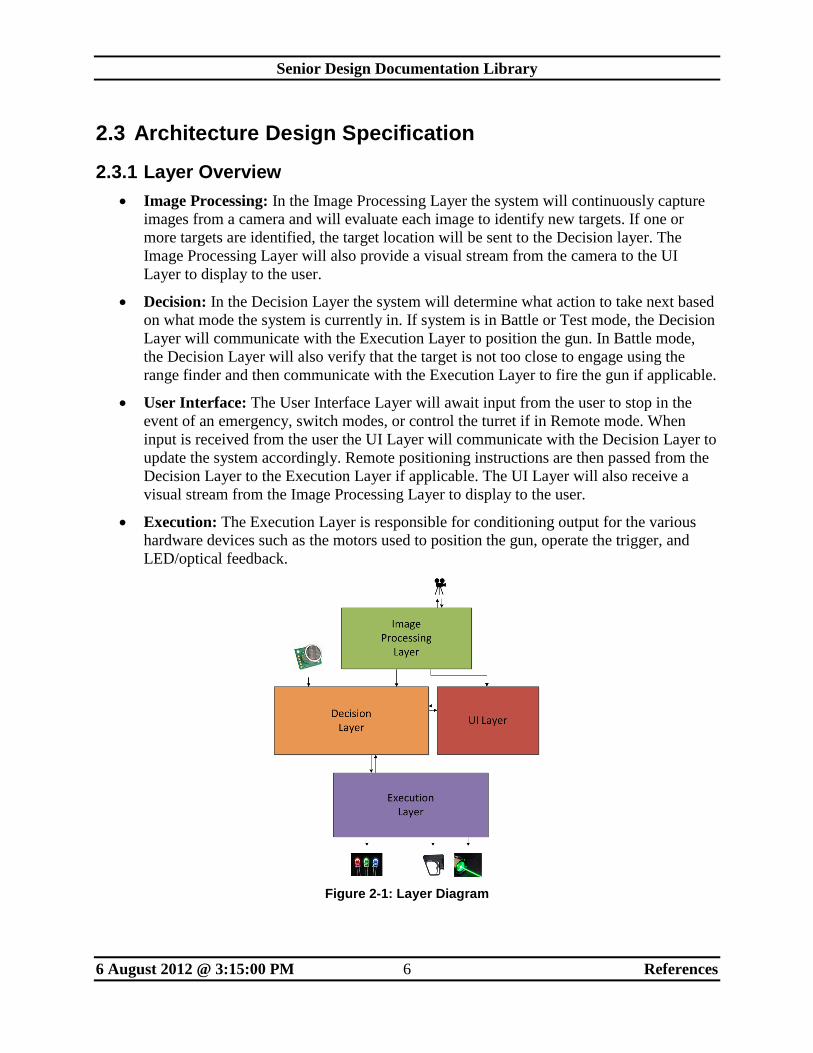
2.3.1 Layer Overview
Image Processing: In the Image Processing Layer the system will continuously capture
images from a camera and will evaluate each image to identify new targets. If one or
more targets are identified, the target location will be sent to the Decision layer. The
Image Processing Layer will also provide a visual stream from the camera to the UI
Layer to display to the user.
Decision: In the Decision Layer the system will determine what action to take next based
on what mode the system is currently in. If system is in Battle or Test mode, the Decision
Layer will communicate with the Execution Layer to position the gun. In Battle mode,
the Decision Layer will also verify that the target is not too close to engage using the
range finder and then communicate with the Execution Layer to fire the gun if applicable.
User Interface: The User Interface Layer will await input from the user to stop in the
event of an emergency, switch modes, or control the turret if in Remote mode. When
input is received from the user the UI Layer will communicate with the Decision Layer to
update the system accordingly. Remote positioning instructions are then passed from the
Decision Layer to the Execution Layer if applicable. The UI Layer will also receive a
visual stream from the Image Processing Layer to display to the user.
Execution: The Execution Layer is responsible for conditioning output for the various
hardware devices such as the motors used to position the gun, operate the trigger, and
LED/optical feedback.
Figure 2-1: Layer Diagram
Senior Design Documentation Library
6 August 2012 @ 3:15:00 PM 7 References
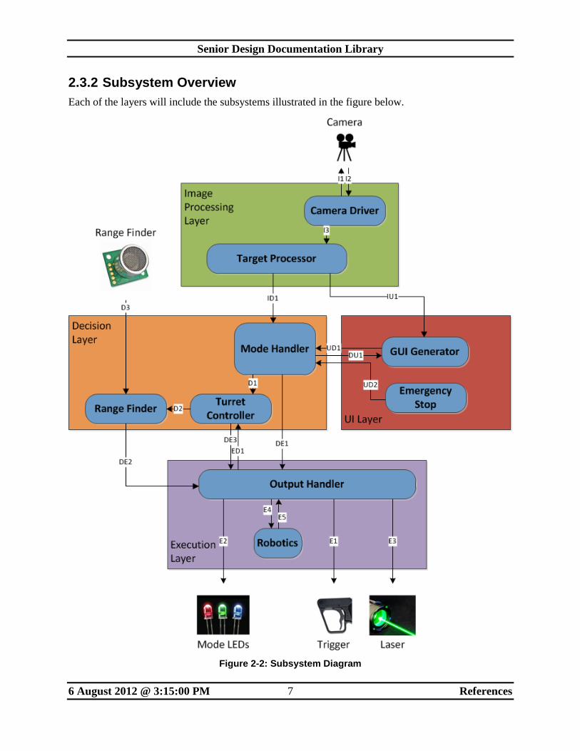
2.3.2 Subsystem Overview
Each of the layers will include the subsystems illustrated in the figure below.
Figure 2-2: Subsystem Diagram
Senior Design Documentation Library
6 August 2012 @ 3:15:00 PM 8 References
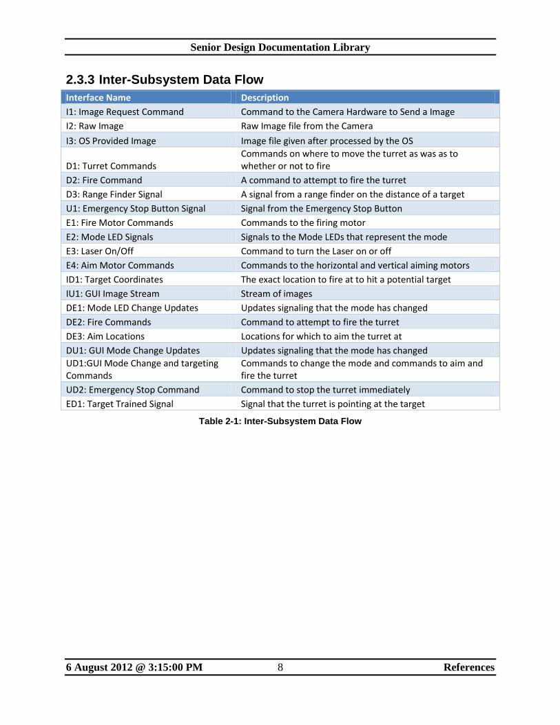
2.3.3 Inter-Subsystem Data Flow
Interface Name Description
I1: Image Request Command Command to the Camera Hardware to Send a Image
I2: Raw Image Raw Image file from the Camera
I3: OS Provided Image Image file given after processed by the OS
D1: Turret Commands Commands on where to move the turret as was as to whether or not to fire
D2: Fire Command A command to attempt to fire the turret
D3: Range Finder Signal A signal from a range finder on the distance of a target
U1: Emergency Stop Button Signal Signal from the Emergency Stop Button
E1: Fire Motor Commands Commands to the firing motor
E2: Mode LED Signals Signals to the Mode LEDs that represent the mode
E3: Laser On/Off Command to turn the Laser on or off
E4: Aim Motor Commands Commands to the horizontal and vertical aiming motors
ID1: Target Coordinates The exact location to fire at to hit a potential target
IU1: GUI Image Stream Stream of images
DE1: Mode LED Change Updates Updates signaling that the mode has changed
DE2: Fire Commands Command to attempt to fire the turret
DE3: Aim Locations Locations for which to aim the turret at
DU1: GUI Mode Change Updates Updates signaling that the mode has changed
UD1:GUI Mode Change and targeting Commands
Commands to change the mode and commands to aim and fire the turret
UD2: Emergency Stop Command Command to stop the turret immediately
ED1: Target Trained Signal Signal that the turret is pointing at the target
Table 2-1: Inter-Subsystem Data Flow
Senior Design Documentation Library
6 August 2012 @ 3:15:00 PM 9 References
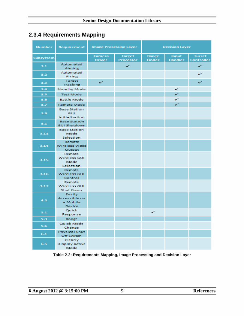
2.3.4 Requirements Mapping
Table 2-2: Requirements Mapping, Image Processing and Decision Layer
Senior Design Documentation Library
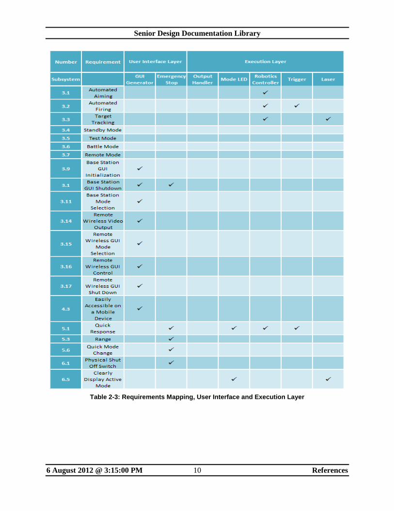
6 August 2012 @ 3:15:00 PM 10 References
Table 2-3: Requirements Mapping, User Interface and Execution Layer
Senior Design Documentation Library
6 August 2012 @ 3:15:00 PM 11 References
2.4 Detailed Design Specification
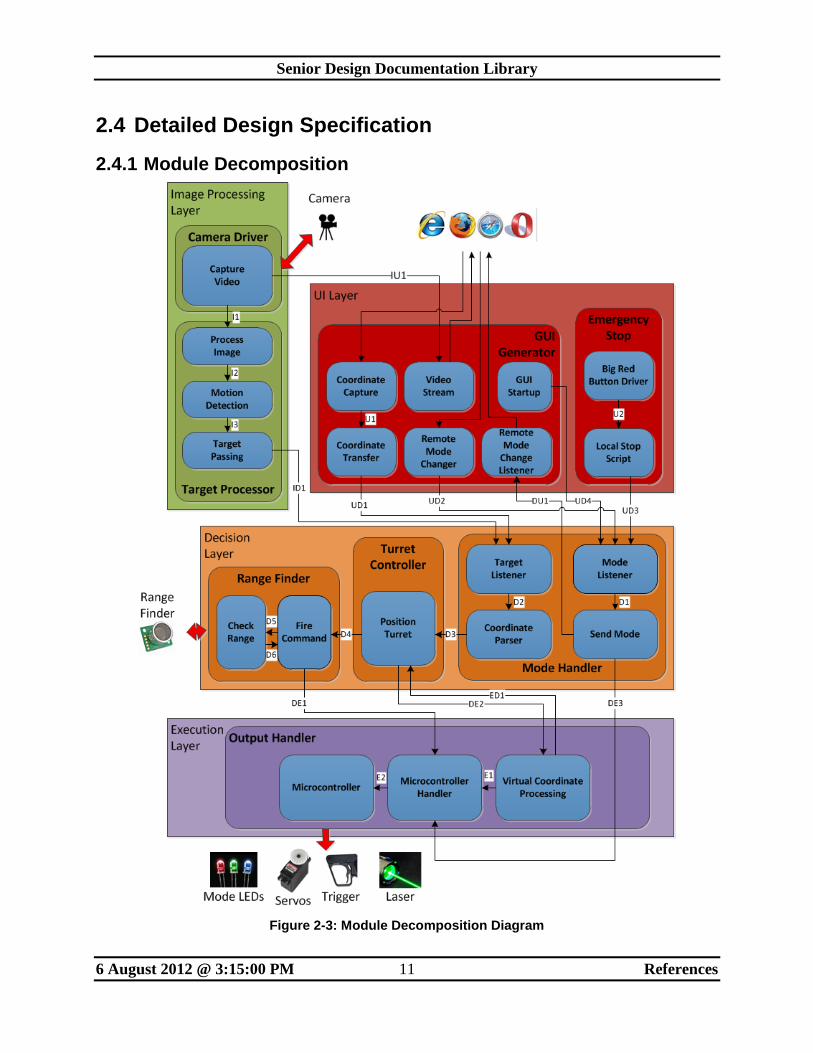
2.4.1 Module Decomposition
Figure 2-3: Module Decomposition Diagram
Senior Design Documentation Library
6 August 2012 @ 3:15:00 PM 12 References
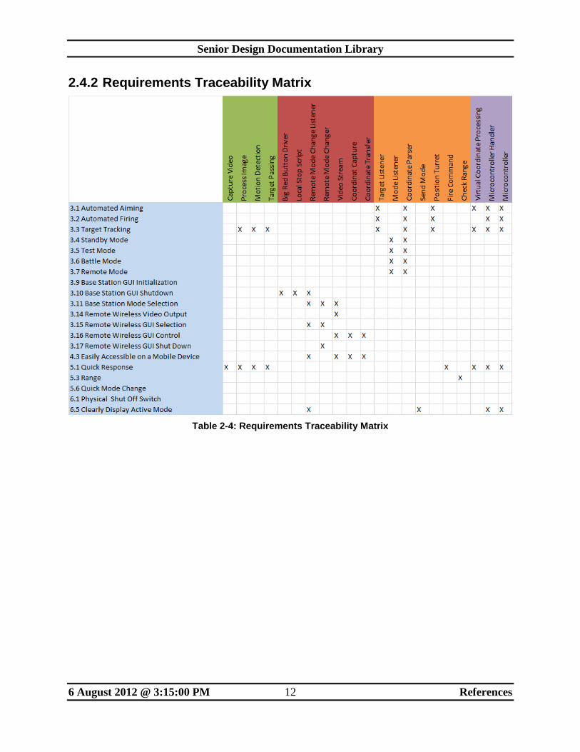
2.4.2 Requirements Traceability Matrix
Table 2-4: Requirements Traceability Matrix
Senior Design Documentation Library
6 August 2012 @ 3:15:00 PM 13 Test Items
3 Test Items
3.1 Overview
This section of the System Test Plan will detail the tests that will be done in order to verify that
the system meets the requirements stated in the SRS. To do this, tests will be broken down into
five incremental stages. These stages are Hardware Testing, Unit Testing, Component Testing,
Integration Testing, and System Verification. Hardware Testing ensures that all low level
hardware works as intended. Unit Testing is the verification of the smallest software units.
Component Testing is the verification of functional units. Integration Testing is the verification
of large functional units. System Verification is testing of whether the completed system meets
the requirements stated by the SRS document.
Senior Design Documentation Library
6 August 2012 @ 3:15:00 PM 14 Test Items
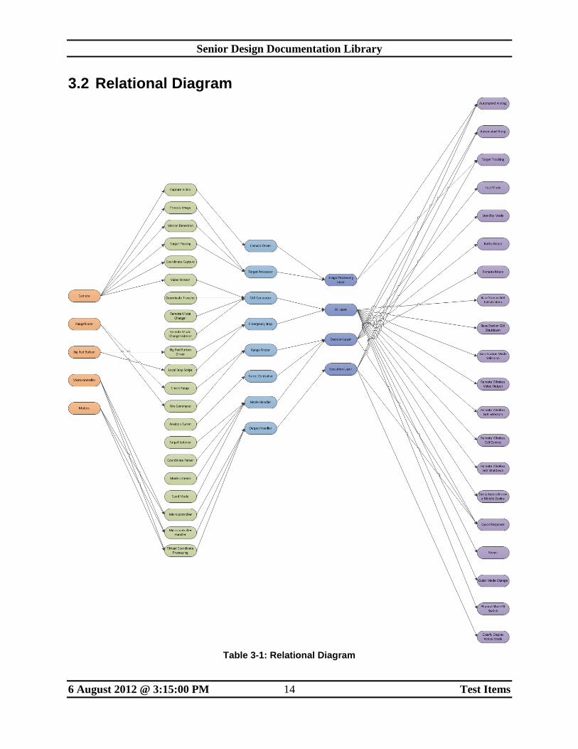
3.2 Relational Diagram
Table 3-1: Relational Diagram
Senior Design Documentation Library
6 August 2012 @ 3:15:00 PM 15 Test Items
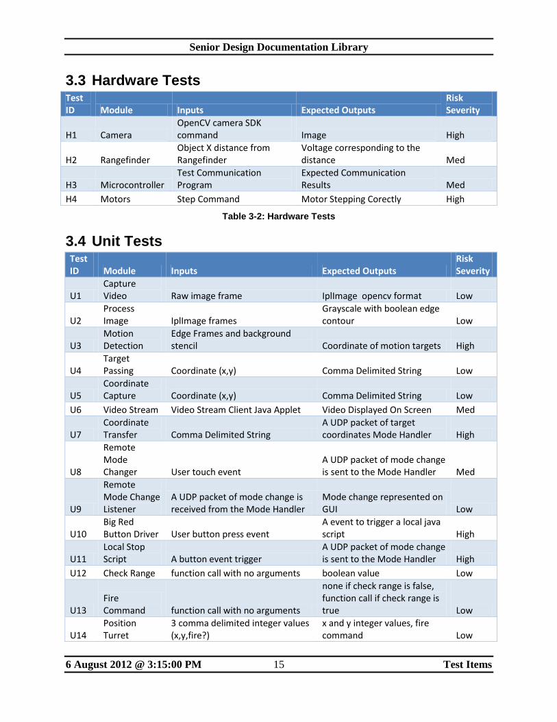
3.3 Hardware Tests Test ID Module Inputs Expected Outputs
Risk Severity
H1 Camera OpenCV camera SDK command Image High
H2 Rangefinder Object X distance from Rangefinder
Voltage corresponding to the distance Med
H3 Microcontroller Test Communication Program
Expected Communication Results Med
H4 Motors Step Command Motor Stepping Corectly High
Table 3-2: Hardware Tests
3.4 Unit Tests Test ID Module Inputs Expected Outputs
Risk Severity
U1 Capture Video Raw image frame IplImage opencv format Low
U2 Process Image IplImage frames
Grayscale with boolean edge contour Low
U3 Motion Detection
Edge Frames and background stencil Coordinate of motion targets High
U4 Target Passing Coordinate (x,y) Comma Delimited String Low
U5 Coordinate Capture Coordinate (x,y) Comma Delimited String Low
U6 Video Stream Video Stream Client Java Applet Video Displayed On Screen Med
U7 Coordinate Transfer Comma Delimited String
A UDP packet of target coordinates Mode Handler High
U8
Remote Mode Changer User touch event
A UDP packet of mode change is sent to the Mode Handler Med
U9
Remote Mode Change Listener
A UDP packet of mode change is received from the Mode Handler
Mode change represented on GUI Low
U10 Big Red Button Driver User button press event
A event to trigger a local java script High
U11 Local Stop Script A button event trigger
A UDP packet of mode change is sent to the Mode Handler High
U12 Check Range function call with no arguments boolean value Low
U13 Fire Command function call with no arguments
none if check range is false, function call if check range is true Low
U14 Position Turret
3 comma delimited integer values (x,y,fire?)
x and y integer values, fire command Low
Senior Design Documentation Library
6 August 2012 @ 3:15:00 PM 16 Test Items
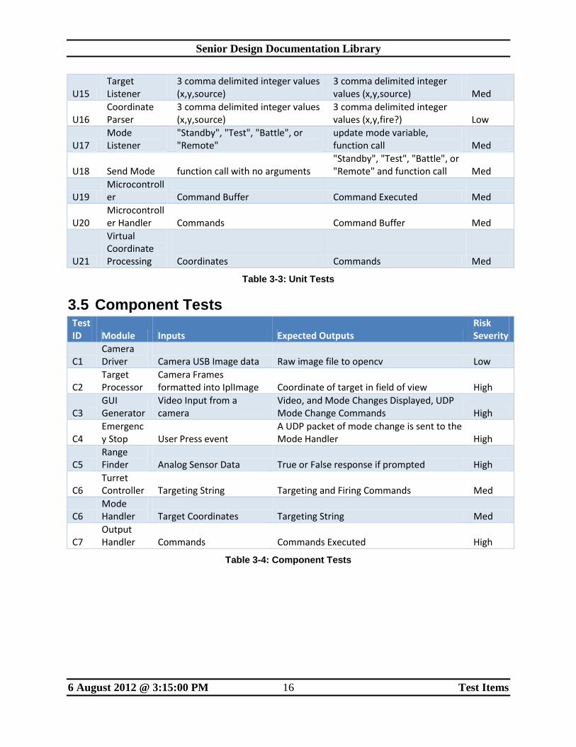
U15 Target Listener
3 comma delimited integer values (x,y,source)
3 comma delimited integer values (x,y,source) Med
U16 Coordinate Parser
3 comma delimited integer values (x,y,source)
3 comma delimited integer values (x,y,fire?) Low
U17 Mode Listener
"Standby", "Test", "Battle", or "Remote"
update mode variable, function call Med
U18 Send Mode function call with no arguments "Standby", "Test", "Battle", or "Remote" and function call Med
U19 Microcontroller Command Buffer Command Executed Med
U20 Microcontroller Handler Commands Command Buffer Med
U21
Virtual Coordinate Processing Coordinates Commands Med
Table 3-3: Unit Tests
3.5 Component Tests Test ID Module Inputs Expected Outputs
Risk Severity
C1 Camera Driver Camera USB Image data Raw image file to opencv Low
C2 Target Processor
Camera Frames formatted into IplImage Coordinate of target in field of view High
C3 GUI Generator
Video Input from a camera
Video, and Mode Changes Displayed, UDP Mode Change Commands High
C4 Emergency Stop User Press event
A UDP packet of mode change is sent to the Mode Handler High
C5 Range Finder Analog Sensor Data True or False response if prompted High
C6 Turret Controller Targeting String Targeting and Firing Commands Med
C6 Mode Handler Target Coordinates Targeting String Med
C7 Output Handler Commands Commands Executed High
Table 3-4: Component Tests
Senior Design Documentation Library
6 August 2012 @ 3:15:00 PM 17 Test Items
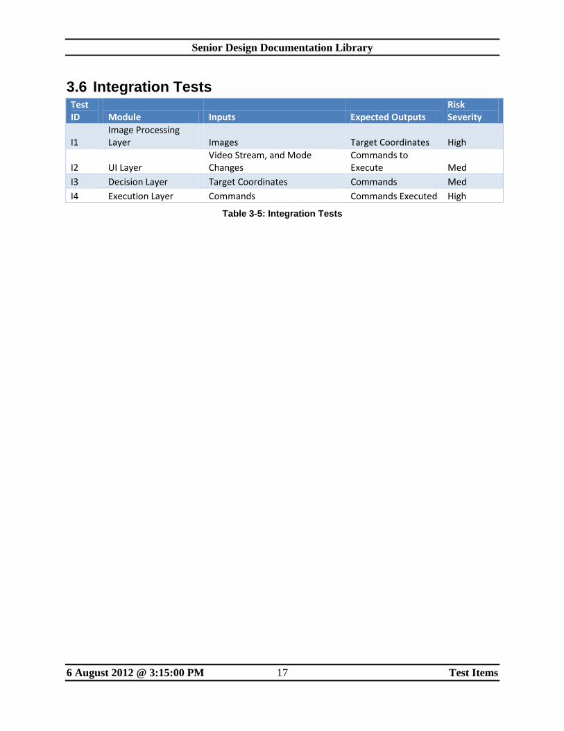
3.6 Integration Tests Test ID Module Inputs Expected Outputs
Risk Severity
I1 Image Processing Layer Images Target Coordinates High
I2 UI Layer Video Stream, and Mode Changes
Commands to Execute Med
I3 Decision Layer Target Coordinates Commands Med
I4 Execution Layer Commands Commands Executed High
Table 3-5: Integration Tests
Senior Design Documentation Library
6 August 2012 @ 3:15:00 PM 18 Risks
4 Risks
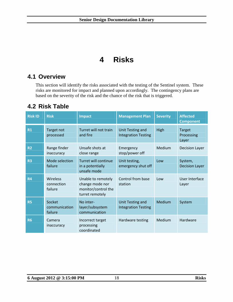
4.1 Overview
This section will identify the risks associated with the testing of the Sentinel system. These
risks are monitored for impact and planned upon accordingly. The contingency plans are
based on the severity of the risk and the chance of the risk that is triggered.
4.2 Risk Table
Risk ID Risk Impact Management Plan Severity Affected Component
R1 Target not processed
Turret will not train and fire
Unit Testing and Integration Testing
High Target Processing Layer
R2 Range finder inaccuracy
Unsafe shots at close range
Emergency stop/power off
Medium Decision Layer
R3 Mode selection failure
Turret will continue in a potentially unsafe mode
Unit testing, emergency shut off
Low System, Decision Layer
R4 Wireless connection failure
Unable to remotely change mode nor monitor/control the turret remotely
Control from base station
Low User Interface Layer
R5 Socket communication failure
No inter-layer/subsystem communication
Unit Testing and Integration Testing
Medium System
R6 Camera inaccuracy
Incorrect target processing coordinated
Hardware testing Medium Hardware
Senior Design Documentation Library
6 August 2012 @ 3:15:00 PM 19 Features to be Tested
5 Features to be Tested
This section lists the features of this project that will be scrutinized and examined to assure that
each module and component meets the requirements specified in the System Requirements
Specification (SRS). Each of the tests will be listed and described as per requirement type such
as Customer Requirement, Packaging Requirement, Safety Requirement, or Other Requirements.
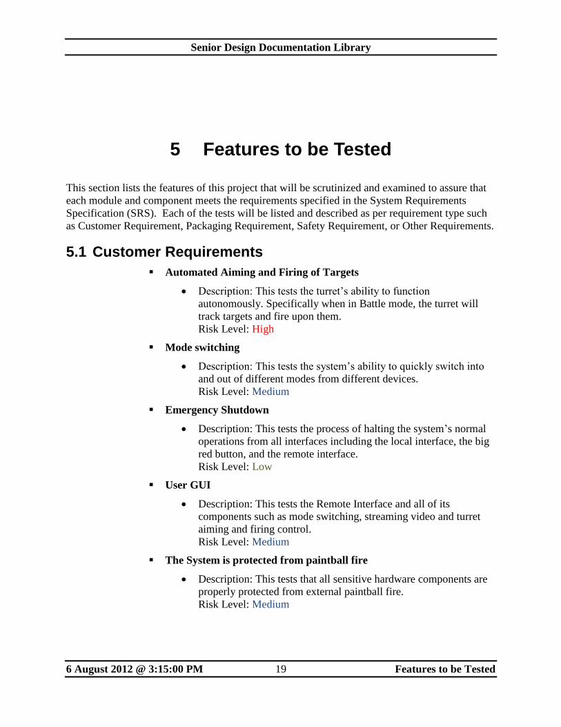
5.1 Customer Requirements
Automated Aiming and Firing of Targets
Description: This tests the turret’s ability to function
autonomously. Specifically when in Battle mode, the turret will
track targets and fire upon them.
Risk Level: High
Mode switching
Description: This tests the system’s ability to quickly switch into
and out of different modes from different devices.
Risk Level: Medium
Emergency Shutdown
Description: This tests the process of halting the system’s normal
operations from all interfaces including the local interface, the big
red button, and the remote interface.
Risk Level: Low
User GUI
Description: This tests the Remote Interface and all of its
components such as mode switching, streaming video and turret
aiming and firing control.
Risk Level: Medium
The System is protected from paintball fire
Description: This tests that all sensitive hardware components are
properly protected from external paintball fire.
Risk Level: Medium
Senior Design Documentation Library
6 August 2012 @ 3:15:00 PM 20 Features to be Tested
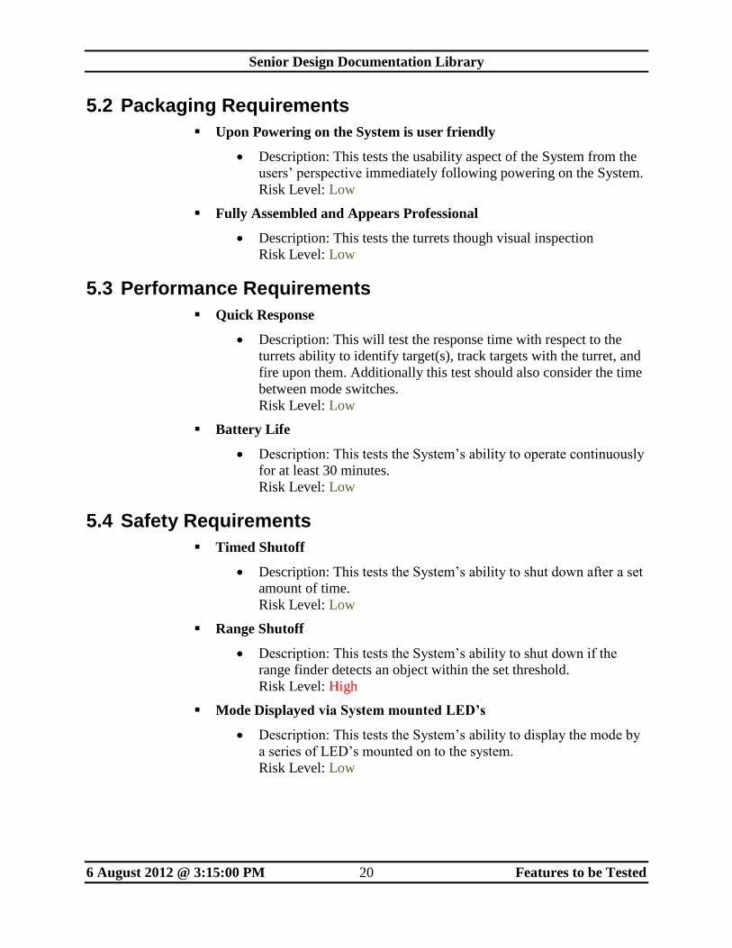
5.2 Packaging Requirements
Upon Powering on the System is user friendly
Description: This tests the usability aspect of the System from the
users’ perspective immediately following powering on the System.
Risk Level: Low
Fully Assembled and Appears Professional
Description: This tests the turrets though visual inspection
Risk Level: Low
5.3 Performance Requirements
Quick Response
Description: This will test the response time with respect to the
turrets ability to identify target(s), track targets with the turret, and
fire upon them. Additionally this test should also consider the time
between mode switches.
Risk Level: Low
Battery Life
Description: This tests the System’s ability to operate continuously
for at least 30 minutes.
Risk Level: Low
5.4 Safety Requirements
Timed Shutoff
Description: This tests the System’s ability to shut down after a set
amount of time.
Risk Level: Low
Range Shutoff
Description: This tests the System’s ability to shut down if the
range finder detects an object within the set threshold.
Risk Level: High
Mode Displayed via System mounted LED’s
Description: This tests the System’s ability to display the mode by
a series of LED’s mounted on to the system.
Risk Level: Low
Senior Design Documentation Library
6 August 2012 @ 3:15:00 PM 21 Features to be Tested
5.5 Maintenance and Support Requirements
Debugging interface
Description: This tests the System’s ability to display the
debugging interface useful for the developers of the System for
testing and advanced usage.
Risk Level: High
Senior Design Documentation Library
6 August 2012 @ 3:15:00 PM 22 Features Not to be Tested
6 Features Not to be Tested
This section lists and describes requirements that cannot be tested due to issues such as
insufficient test capability, low risk feature that is hard to test or the feature is simply not
testable.
Precise Accuracy
o Precise accuracy will not be tested due to the inability to automate any
quantifiable (and inexpensive) method.
Surrender Gesture
o The turret will not be tested over its ability to recognize and switch modes based
on a surrender gesture made by the target because it is a future requirement that
will most likely not be implemented.
Active Feedback
o The turret will not be tested over its ability to actively adapt to the targets
movements and speed because this is a future requirement and information will be
preprogrammed into the turret to account for distance and target movement.
Senior Design Documentation Library
6 August 2012 @ 3:15:00 PM 23 Approach
7 Approach
7.1 Overview
This section describes in detail how Team PAINTeK will carry out the testing approach and
maintain records of the tests.
7.2 Overall Test Strategy
Team PAINTeK will utilize both Black Box and White Box testing (as per the ADS and
DDS testing plans) to ensure that the system will meet the requirements defined in the SRS.
The system must also comply with the ADS and DDS specifications which were written to
reflect the SRS in a stable and fundamental way. The tests will be documented utilizing the
following strategy:
Test ID
Test Type (unit, component, singular, etc)
Test Date
Results and outputs
Pass or Fail
Comments, details, plans to correct errors, and severity of errors.
7.3 Hardware and Software Configurations
There are a number of hardware and Software components that must be tested to ensure that
they are reliable enough to handle their tasks in the Sentinel Project. The plan enacted in this
section will ensure that the defects in the hardware are minimal.
Test Name/Test ID
Test Type Hardware/Software
Fixed/Ignored
Results
Pass or Fail
Comments, details, contingency plans and severity of errors.
Senior Design Documentation Library
6 August 2012 @ 3:15:00 PM 24 Approach
Any bugs or defects that are critical to the systems success will be evaluated and carried out
as a team in order to better resolve and fulfill the needs of all subsystems. Some issues will
likely be non-severe and can be handled according to our own development.
7.4 Testing Metrics
The success of the prototype will be measured through our test cases and based on their
priority in our SRS. A successful prototype will need to ensure that all high priority
requirements are fulfilled and the acceptance criteria are met. This ensures that the prototype
will be acceptable to the end user and all stakeholders before the product is considered for
further production. Other test cases will be on a pass or fail basis and will be presented
accordingly regardless of whether or not they actually fulfilled the project requirement.
7.5 Testing Requirements
If a change must be made in the source code to better implement a failed component in
testing, regression testing will be carried out to ensure that any changes did not introduce
new errors to subsequent systems that utilized information that may have been changed. The
team will log the results of their changes and the regression testing.
Senior Design Documentation Library
6 August 2012 @ 3:15:00 PM 25 Test Deliverables
8 Test Deliverables
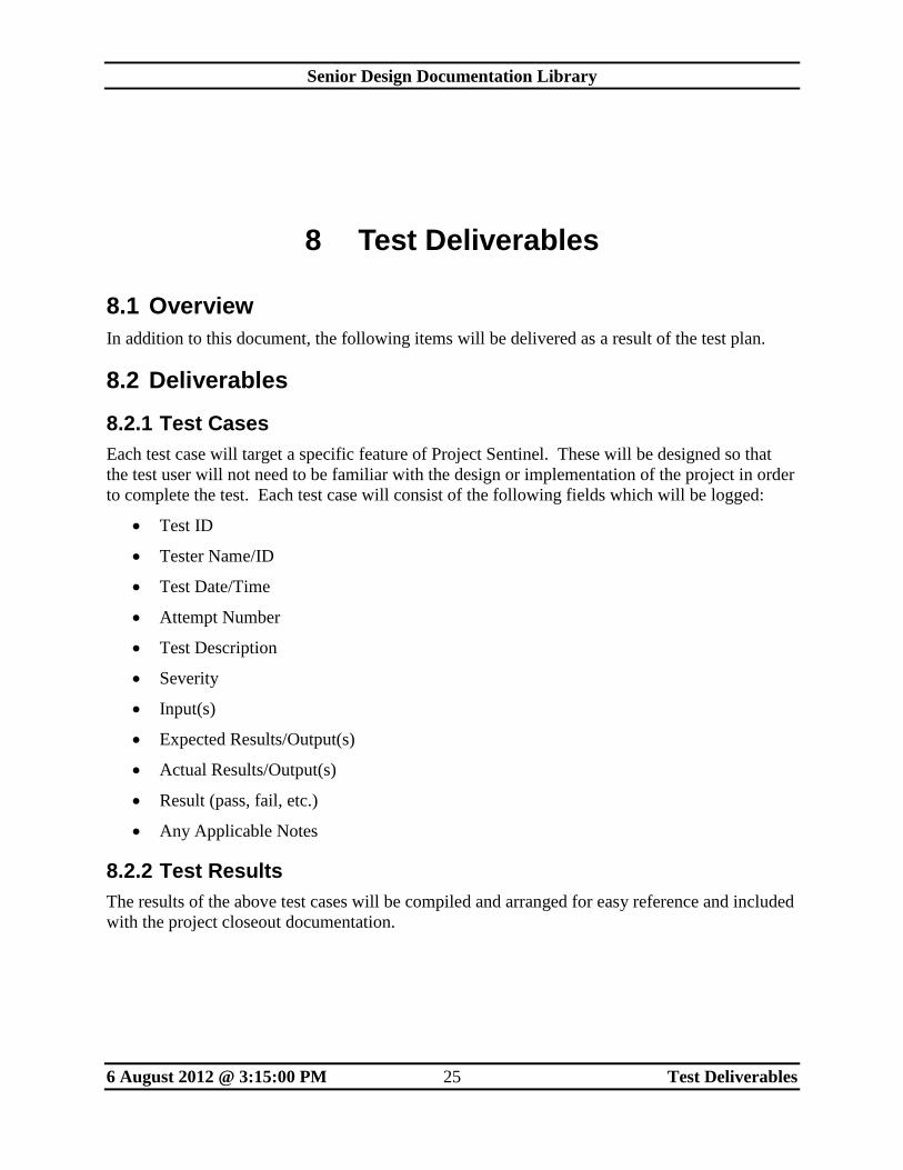
8.1 Overview
In addition to this document, the following items will be delivered as a result of the test plan.
8.2 Deliverables
8.2.1 Test Cases
Each test case will target a specific feature of Project Sentinel. These will be designed so that
the test user will not need to be familiar with the design or implementation of the project in order
to complete the test. Each test case will consist of the following fields which will be logged:
Test ID
Tester Name/ID
Test Date/Time
Attempt Number
Test Description
Severity
Input(s)
Expected Results/Output(s)
Actual Results/Output(s)
Result (pass, fail, etc.)
Any Applicable Notes
8.2.2 Test Results
The results of the above test cases will be compiled and arranged for easy reference and included
with the project closeout documentation.
Senior Design Documentation Library
6 August 2012 @ 3:15:00 PM 26 Test Deliverables
8.2.3 Bugs and Defects
Any unresolved system issues will be documented for future reference. This documentation will
include:
Expected Behavior
Actual Behavior
Impact to System
Action Taken to Attempt to Resolve
Reason that the issue could not be resolved in this release
8.2.4 Test Code
Any code that is written to test a module or system will be archived and provided with the
project closeout documentation.
8.2.5 Software
Any third party applications that are used to test Project Sentinel will be referenced in the project
closeout documentation.
Senior Design Documentation Library
6 August 2012 @ 3:15:00 PM 27 Test Schedule
9 Test Schedule
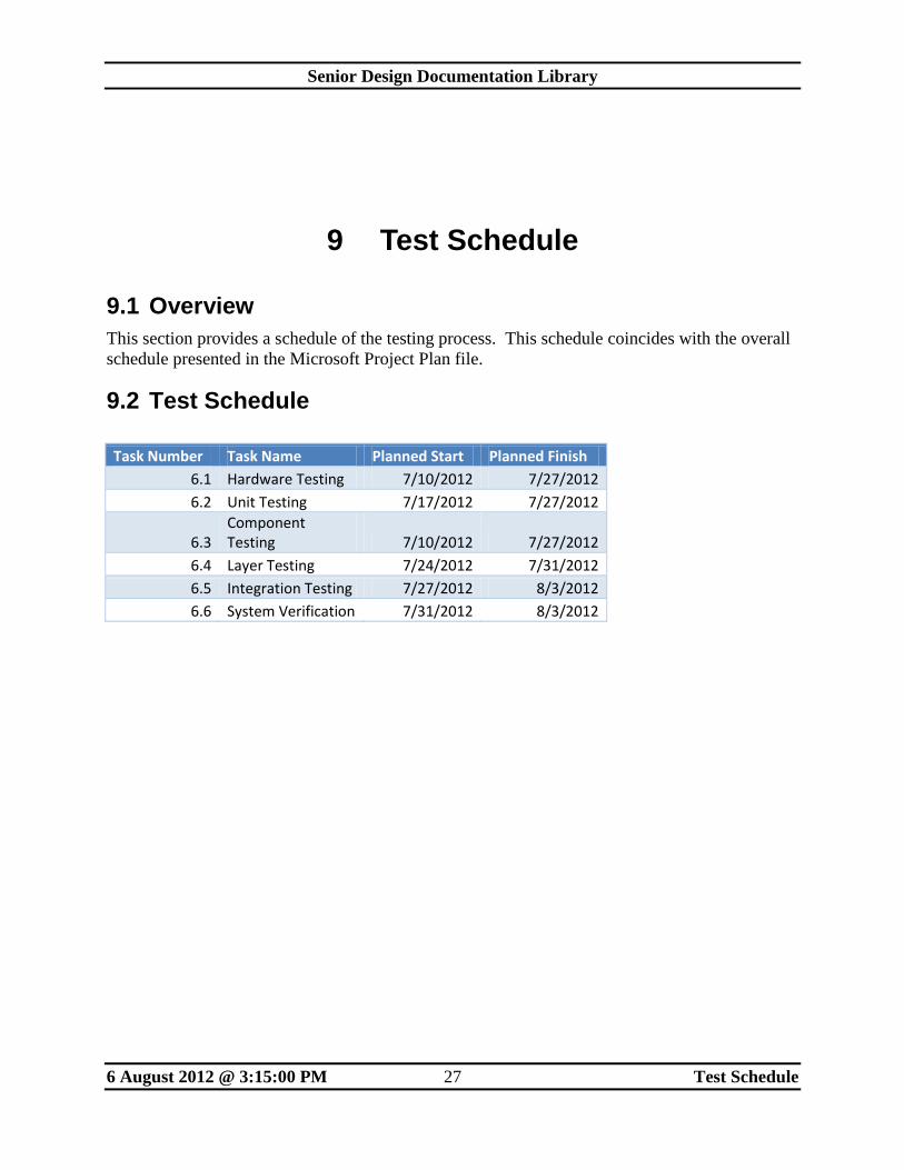
9.1 Overview
This section provides a schedule of the testing process. This schedule coincides with the overall
schedule presented in the Microsoft Project Plan file.
9.2 Test Schedule
Task Number Task Name Planned Start Planned Finish
6.1 Hardware Testing 7/10/2012 7/27/2012
6.2 Unit Testing 7/17/2012 7/27/2012
6.3 Component Testing 7/10/2012 7/27/2012
6.4 Layer Testing 7/24/2012 7/31/2012
6.5 Integration Testing 7/27/2012 8/3/2012
6.6 System Verification 7/31/2012 8/3/2012
Senior Design Documentation Library
6 August 2012 @ 3:15:00 PM 28 Approvals
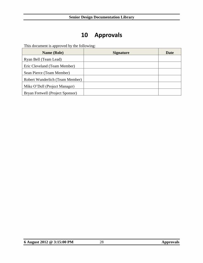
10 Approvals
This document is approved by the following:
Name (Role) Signature Date
Ryan Bell (Team Lead)
Eric Cleveland (Team Member)
Sean Pierce (Team Member)
Robert Wunderlich (Team Member)
Mike O’Dell (Project Manager)
Bryan Fretwell (Project Sponsor)