Embed Size (px)
Citation preview

DEPARTMENT OF ENERGY ENERGY UTILIZATION MANAGEMENT BUREAU
Micro-hydropower Operator Training Manual
May 2009
MHP – 5

This manual was developed by the Department of Energy (DOE) through the technical assistance under the Project on “Sustainability Improvement of Renewable Energy Development for Village Electrification in the Philippines” which was provided by the Japan International Cooperation Agency (JICA).
Table of Contents
1. General ................................................................................................................ 1
2. Scope ................................................................................................................... 1
3. Objectives ............................................................................................................ 1
4. Roles of Operators ............................................................................................... 1
5. Operation Work ................................................................................................... 2
5.1 Intent of Operation ............................................................................................ 2
5.2 Basic operation .................................................................................................. 2
5.3 Operations in the Event of an Emergency .......................................................... 5
5.4 Others (other types of operation) ....................................................................... 6
6. Patrol ................................................................................................................... 7
6.1 Patrol for hydropower stations........................................................................... 7
6.2 Daily patrol items .............................................................................................. 9
7. Maintenance....................................................................................................... 10
7.1 Breakdown and Preventive Maintenance ......................................................... 10
7.2 Daily Maintenance........................................................................................... 11
7.3 Maintenance for the trouble and failure ........................................................... 11
7.4 Periodic Maintenance ...................................................................................... 12
8. Recording........................................................................................................... 12
9. ‘Model Training Schedule’ for the training of new operators ............................ 12
10. Amendment of the manual ................................................................................. 13

LIST OF ANNEXES
ANNEX 1 : Check sheet
1
1. General Micro-hydropower plants for rural electrification should be operated and
maintained by well-trained operators to ensure a stable supply of electricity to
electrified communities. This manual specifies operator-training concepts that are to
be put into practice at the project site prior to the handing over of the facilities.
Specific contents of the actual training, therefore, shall be adequately reviewed to
meet the practical conditions of which this manual will serve as a reference.
2. Scope This manual shall be used as instructional material for DOE staff and/or designated
implementers who have been assigned to conduct operator training.
3. Objectives The objectives of this manual are:
(1) To identify the roles and responsibilities that operators should undergo in order
to properly operate and maintain micro-hydropower plants, and
(2) To assist the project implementer in preparing operation and maintenance
manuals for newly constructed micro-hydropower plants.
4. Roles of Operators Micro-hydropower plants must be operated and maintained in strict compliance
with O & M (Operation and Maintenance). In general, operators of micro hydropower
plants should understand the following items:
(1) Operators must efficiently conduct O & M of micro-hydropower plants in strict
compliance with the rules and regulations.
(2) Operators must familiarize themselves with all plant components and their
respective performance or functions. Furthermore, they should also be familiar
with prompt recovery emergency measures should an accident occur.
(3) Operators must always check the condition of facilities and equipment. If
trouble is found or an accident occurs, they must inform the person in charge
and try to solve the problem.
(4) Operators must try to prevent any accidents. Preventative measures such as
equipment repair and the improvement of the facilities should be implemented
as necessary.
(5) An operation and maintenance manual should be prepared for each plant before
the start of its operation.

2
5. Operation Work The operation of micro-hydropower plants is to not only generate electric power,
but also to control generation equipment, supply stable, high quality electricity to
consumers, and maintain the condition of all facilities.
Most rural electrification micro-hydro plants are not equipped with suitable automatic
control systems and protection equipment due to budget constraints. Therefore, it is
necessary for operators to stay at or near the plant to monitor control equipment and to
undertake immediate measures in the case of an emergency.
5.1 Intent of Operation
Hydropower station operators should be highly motivated to keep their power
stations in good condition to ensure a stable supply of electric power. Operators
should be aware of any signs and/or signals indicating equipment malfunction and
take advance preventative measures. Examples of the intention of operation are listed
below.
(1) Familiarize oneself with operation-related regulations, rules, and manuals of
the power station, distribution lines, and loads.
(2) Familiarize oneself with the civil structures, electric circuits, control system,
etc. of the power station in detail.
(3) Grasp the operational conditions of the power station
(4) Maintain highly efficient operations.
(5) Avoid abnormal operation (e.g. low output operation) because of damage to
water turbines by large vibrations, cavitation damages, etc.
(6) Check and maintain a grasp of the equipment conditions via periodic and
methodic patrolling of the power station.
(7) Compare and contrast past recorded data with present data to confirm the
equipment conditions.
5.2 Basic operation
(1) Pre-operational Check points
Before operation commences, the following facilities and equipment must be
checked by operators to ensure that they are in proper operating condition.
Especially for long-term operation, it is of particular importance that these items are
checked thoroughly.

3
a. Transmission and distribution lines
(a) Line and pole damage
(b) Nearby branches
(c) Other obstacles
b. Waterway facilities
(a) Structural damage
(b) Sand sedimentation in front of the intake
(c) Suspended trash at the screens
(d) Sand sedimentation in the settling basin and the forebay
c. Turbine, generator, and controller
(a) Visual inspection
(b) Wear of the brush
(c) Insulation resistance of the circuits
(2) Starting operation
Start-up of operation is as follows (typical example):
(a. Preparation)
(a-1) Close the flushing gate of the intake weir
(a-2) Open the intake gate and intake water into the waterway system.
(b. Starting operation)
(b-1) Open the inlet valve gradually.
(b-2) If there is a guide vane, open the inlet valve fully, and then open the guide
vane gradually.
(b-3) Use a controller (e.g. ELC) if one exists. Confirm that voltage and frequency
or rotating speed increase up to the regulated value by guide vane (or inlet
valve).
(b-4) Turn the load switch on (parallel in).
(b-5) Control the inlet valve or guide vane so that voltage and frequency are within
the regulated range.
The start-up procedure is designed based on the equipment at each power station.
Based on the knowledge of each machine, it is important to understand the logic
behind these steps.

4
Prior to starting operation of the main units, the following conditions have to be
generally kept. These conditions are called the ‘Preparation for operation’.
(a-1)(a-2) Close the flushing gate of the intake weir and open the intake gate and
intake water into the waterway system.
The water turbine is driven by water from the waterway system. If the water flow
is shut off by the intake gate or valve, water cannot be fed to the water turbine. In
situations where the ability to close the intake gate (or valve) is limited, the water
remaining in the penstock flows down by the force of its own weight after the
opening of the inlet valve (and guide vane), but supplemental air cannot go into the
penstock. This lowers the pressure within the penstock. In the worst case scenario,
the build up of air pressure breaks the penstock.
(a-3) Others
(a-3-1) Bearing lubricant condition
Bearings are delicate parts that maintain stable operation of the units. Periodic
application of grease is important for stable and long-term use of the bearings
and main units. When lubrication of bearings is insufficient for operations, this
means that the bearings have burned out and must be replaced.
(a-3-2) Cooling water of dummy load for ELC
Generator frequency output is controlled by the ELC. The ELC uses a dummy
load (a resistance unit) to consume electric power over the necessary load
supply at that time. If the dummy load is cooled by water, operators should
confirm the water level of the dummy load before operation begins. (The
typical cooling methods of dummy loads are water cooling and air cooling.)
(a-3-3) Protection relays for emergency stop are not activated
When a series of failures occurs in the units, protection relays (and automatic
cut-off by circuit breakers) are activated for an emergency shutdown of the
units. Once the failures are corrected, they can be manually reset by the
operators.
The excitation current of the AVR system increases the terminal voltage of the
generator. When it reaches its approximate rated voltage (and frequency or rotation
speed reaches its rated value), operators turn on the load switch (generator circuit
breaker) to connect the generator to the transmission (distribution) lines.

5
(3) Roles of Operators during Operation
Operators must maintain control over the equipment so that the supply of quality
electricity may be realized in order to maintain equipment conditions and ensure
safety factors as follows:
(c-1) Control the inlet valve or guide vane so that voltage and frequency are within
their regulated range.
(c-2) Check for equipment and noise vibration, and stop operations if necessary.
(c-3) Check the temperature of the equipment.
(c-4) Check the equipment conditions. Stop operation and apply the appropriate
countermeasures if necessary.
(c-5) Record operation results and equipment condition
(4) Stopping Operation
In order to avoid longer runaway speed of the turbine and the generator, the
procedures for stopping operation are as follows:
(d-1) Close the inlet valve or the guide vane.
(d-2) Cut load switch off (load rejection).
(d-3) Close the inlet valve and the guide vane completely.
(d-4) Close the intake gate.
If the load is suddenly cut due to an accident, the operator must close the inlet
valve or the guide vane immediately to avoid prolonged periods of the runaway
speed of the turbine and the generator.
5.3 Operations in the Event of an Emergency
(1) Flood Conditions
In general, micro-hydropower plants can operate even during flood conditions.
However, when the river becomes muddy leading to a possibility of sand and/or soil
intrusion into the facilities, plant operations should be stopped by closing the intake
gate. After the floodwater recedes, operators must inspect all facilities prior to
resuming operation.
(2) Earthquake
Operators must inspect all facilities after a big earthquake as follows:

6
・ Structural damage
・ Misalignment of the turbine and the generator shaft
・ Damage of the other electrical equipment
・ Others
(2) Water Shortage / Drought Conditions
Micro-hydropower plants should basically be designed in accordance with the
amount of water discharge in the dry season. However, in the case of drought
conditions, operators must stop operation to prevent turbine damage.
(4) Accidents (Troubles)
When accidents occur, operators must stop operation, investigate the cause, and
then try to recover operation as soon as possible. An operator’s roles are as follows:
(a) Immediately inform the person in charge of the accident.
(b) Investigate the details of the accident.
(c) Investigate the causes of the accident.
(d) Recover operation as soon as possible if operators can determine the causes and
perform the necessary repairs by themselves.
(e) Contact technical advisors, manufacturers, or equipment suppliers and request
them to perform the repair(s) if the operators cannot discover the cause(s) and/or
cannot perform the repair(s) by themselves.
Preparations that operators should make in advance are as follows:
(a) Discuss possible countermeasures for the trouble with technical advisors,
manufacturers or equipment suppliers.
(b) Report the accidents to the DOE and LGU.
5.4 Others (other types of operation)
(1) Filling of the waterway system
Filling procedures for the waterway system are as follows:
(a) Confirm that all flushing gates and valves of the water system are open.
(b) Open the intake gate partially and input a small volume of water.
(c) Close the flushing gate of the settling basin after cleaning the settling basin.
(d) Close the flushing gate of the forebay after cleaning the headrace and the
forebay.

7
(e) Close the drain valve of the penstock after cleaning the penstock.
(f) Fill the penstock with water gradually.
(g) Open the intake gate fully after filling up the penstock.
(2) Flushing sand in front of the intake
If sand sedimentation reaches the intake level, sand will be carried into the
waterway system and affect the penstock and turbine blades. Therefore, in order to
prepare against an outflow of sand and soil during flooding, operators must keep the
intake approach open. For this purpose, operators should sometimes flush or remove
the sand that has settled in front of the intake.
If a flushing gate is installed at the intake weir, operators can flush sand out using
the water flow by opening the gate during flooding. However, if not equipped with
a flushing gate, operators must manually remove the sand from the weir.
(3) Control of intake water
The volume of intake water changes according to the water level of the river.
Normally excess water should be released into the spillway, which is located at the
settling basin or headrace. If excess water reaches the spillway of the forebay for a
long period of time, it may possibly wash out the structure due to a lack of spillway
capacity. Therefore, operators must control the intake gate so as to avoid excessive
water spillage.
6. Patrol Operators patrol the waterway facilities, electric equipment, and transmission and
distribution lines on a daily basis in order to confirm that they are in proper working
order. Operators must record the results of the patrol and take countermeasures if any
troubles should occur.
In this manual, the definition of ‘patrol’ means to conduct a visual inspection of the
hydropower station and confirm the condition of the equipment, the facilities, and the
surrounding areas.
6.1 Patrol for hydropower stations
For the prevention of failures and faults in hydropower stations and to ensure
appropriate operation and maintenance, patrols should be conducted as described
below.

8
a. Types of patrol
(a) Daily patrol
The daily patrols are carried out to confirm the presence and/or absence of
abnormalities at the power stations.
(b) Special patrol
The status of various facilities shall be checked specifically by these patrols
before and after any abnormal weather conditions (heavy rainstorms, flood, etc.),
and immediately after earthquakes.
b. Application of the Patrol Table Checklist
(a) For the daily and detailed patrol, a ‘patrol table checklist’ according to the actual
conditions of various facilities should be made and used.
(b) The ‘Patrol Table Checklist’ shall be prepared
c. Recording and reports
(a) Operators (or related staff) should make records of the patrol in the ‘Patrol Table
Checklists’ and report these results to the person in charge of whatever operation is
a matter of concern. These patrol results should be kept properly to ensure easy use
and access by other operators.
(b) When abnormalities are found, follow-up measures must be implemented
e. Points to be noted for patrols
(a) Any abnormality found during a patrol must be reported to the person in charge of
the indicated trouble operation, and appropriate corrective measures must be taken.
In emergency cases, emergency measures should be implemented in a safe and
thorough manner by the operator, and after that the person in charge of its operation
should be promptly notified.
(b) Patrols shall be carried out based on certain points of emphasis that were
determined by taking the conditions of the hydropower station into consideration.
These include not only seasonal or weather conditions, equipment characteristics
and their operational conditions, but also previous records.
(c) The condition of the meters, indicators, and relays should be checked appropriately,
as well as the connection conditions of each terminal.

9
6.2 Daily patrol items
Daily patrol check items for micro-hydropower stations are as follows:
Table 6.2.1 Daily patrol items
Facilities and Equipment
Checking Points Measures
Suspended Trash at screen Remove the debris.
Water leakage from weir and gate
Record it and make repairs if necessary
Sand sedimentation Flush out as necessary. Intake and Waterway
Deformation or Crack in structure
Record and make repairs if necessary.
Sedimentation Basin Sand sedimentation Flush out as necessary.
Suspended materials along canal
Remove the debris.
Sand sedimentation Flush out as necessary.
Leakage, deformation and
Crack in structure Record it and make repairs if necessary.
Headrace
Land slide along headrace Remove the sand and rocks after confirming the safety.
Suspended Trash at screen Remove the debris.
Overflow from Spillway Reduce water intake if overflow of water is too great.
Water leakage Record it and make repairs if necessary.
Sand sedimentation Flush out as necessary
Head tank (Forebay)
Deformation or Crack in structure
Record it and make repairs if necessary.
Penstock Leakage and deformation Record it.
Strange sound and vibration Record it and make repairs if necessary. Turbine
Leakage from housing Record it and make repairs if necessary.
Strange sound and vibration Record and make repairs if necessary.
Temperature Record it Generator
Belt Damage Replace if necessary
Performance of load stabilizer Check the performance Load stabilizer
Damage of heater Replace if necessary
Transformer Leakage of oil Replace if necessary
Suspended material Remove after stopping operation. Transmission and
Distribution lines Approaching branch Cut it as necessary
10
7. Maintenance Over time some parts of the hydropower station facilities will deteriorate or wear
out. Casings, guide vanes, runners, etc. often deteriorate due to cavitation damage,
corrosion and erosion, or wear of areas at narrow gaps. As a result, the efficiency of
the water turbines decreases little by little coupled with increasing water turbine
vibration and noise.
In order to maintain long-term optimal operating conditions of the micro
hydropower plants, waterway facilities, electric equipment, and transmission and
distribution lines should be adequately maintained.
7.1 Breakdown and Preventive Maintenance
There are basically two maintenance methods concerning the maintenance of power
station equipment: breakdown maintenance and preventive maintenance. Determining
which method to adopt depends on the situation, equipment and the concepts of the
implementers.
In the case of breakdown maintenance, power stations are only stopped in the event
of trouble occurring. This means maintenance expenses will inevitably ensue if
trouble occurs. Moreover, power stations are run continuously at the maximum
amount of generation if no trouble occurs. However, once trouble occurs a forced
outage is required to fix the trouble. This means that the duration of a forced outage
for breakdown maintenance will generally be longer than that of one for preventive
maintenance. Further, a sufficient amount of on-hand spare parts are required for
repairs to shorten the duration of the forced outage. Given these factors, breakdown
maintenance is generally considered less reliable and more costly for long-term
operations.
Table 7.1.1 Difference between breakdown and preventive maintenance
Breakdown maintenance ・ No need to stop power stations unless trouble occurs.
・ No expense until trouble occurs.
・ Forced outage
・ Lack of spare parts delays replacement of the
equipment.
・ Reserve capacity of the power system is required.
・ Increased risk of major damage.
11
Preventive maintenance ・ Planned outage
・ Reduction of reserve capacity based on a lower ratio
of forced outages.
・ Parts procurement before maintenance.
・ Only replacement of consumable parts and minor
repair in many cases.
・ Necessary to stop power station or units.
・ Regular expenses are required based on a maintenance
plan.
On the other hand, for preventive maintenance, power stations are stopped regularly
based on a maintenance plan. However, the duration of the forced outage and
probability of trouble is lower because the maintenance is conducted regularly to keep
power stations operating under stable and reliable conditions. For preventive
maintenance, it is crucial to formulate and coordinate maintenance plans which consist
of contents, the duration of planned outages, the facilities that will be required to be
stopped, etc. Each plan must be coordinated in consideration of the power system
conditions. Maintenance consists of replacing consumable parts and conducting minor
repairs, therefore preplanned budgetary steps and procurement are also necessary.
7.2 Daily Maintenance
Operators should conduct daily maintenance if they find equipment abnormalities
during their daily patrol. Daily maintenance is usually conducted without stopping the
water turbine and dewatering the pipe. During the daily maintenance, the operators
should be careful of rotating parts, moving parts, live parts, and so on. The operators
shall engage in the following duties as daily maintenance.
(a) Cleaning equipment
(b) Retightening valves and volts
(c) Others (refer to Daily patrol items)
7.3 Maintenance for the trouble and failure
If the operators find any trouble and/or failure, they should confirm present
conditions and take countermeasures to prevent the spread of accidents. The operators
should also record their present condition and the countermeasures being taken. This
record will serve as valuable data for the implementers.
12
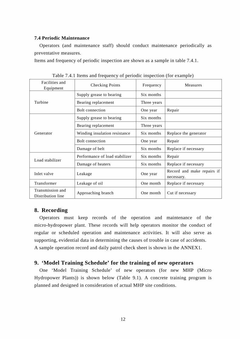
7.4 Periodic Maintenance
Operators (and maintenance staff) should conduct maintenance periodically as
preventative measures.
Items and frequency of periodic inspection are shown as a sample in table 7.4.1.
Table 7.4.1 Items and frequency of periodic inspection (for example)
Facilities and Equipment
Checking Points Frequency Measures
Supply grease to bearing Six months
Bearing replacement Three years Turbine
Bolt connection One year Repair
Supply grease to bearing Six months
Bearing replacement Three years
Winding insulation resistance Six months Replace the generator
Bolt connection One year Repair
Generator
Damage of belt Six months Replace if necessary
Performance of load stabilizer Six months Repair Load stabilizer
Damage of heaters Six months Replace if necessary
Inlet valve Leakage One year Record and make repairs if necessary.
Transformer Leakage of oil One month Replace if necessary
Transmission and Distribution line
Approaching branch One month Cut if necessary
8. Recording Operators must keep records of the operation and maintenance of the
micro-hydropower plant. These records will help operators monitor the conduct of
regular or scheduled operation and maintenance activities. It will also serve as
supporting, evidential data in determining the causes of trouble in case of accidents.
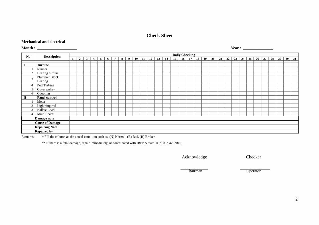
A sample operation record and daily patrol check sheet is shown in the ANNEX1.
9. ‘Model Training Schedule’ for the training of new operators One ‘Model Training Schedule’ of new operators (for new MHP (Micro
Hydropower Plants)) is shown below (Table 9.1). A concrete training program is
planned and designed in consideration of actual MHP site conditions.

13
Table 9.1 An example of ‘Model Training Schedule’
Day Contents of training Notes
AM Introduction of a MHP
Roles of MHP operators
Introduction of the MHP management
system
General explanation
General explanation
Based on the actual MHP
1st Day
PM
System of the MHP
Structure of MHP facilities
Characteristics of MHP equipment
Based on the actual MHP
Based on the actual MHP
Based on the actual MHP
2nd Day
Operation work of the MHP
Contents of operation work
Method of operation of Civil Engineering
Facilities and records
Method of operation of Electrical &
Mechanical Facilities and records
General and detailed
explanation of the actual
MHP.
3rd Day
Daily Patrol and Maintenance work of the MHP
Daily Patrol work and records
Contents of maintenance work
Examples of trouble, extraordinary
conditions and the countermeasures
Method of maintenance and records
General and detailed
explanation of the actual
MHP.
4th Day
- 5th Day
Site inspection of the existing MHP
Experience of the operation
Experience of the maintenance
Discussion with the operators
10. Amendment of the manual The DOE shall review this manual annually, and amend it, if necessary, according
to the surrounding circumstances in rural electrification of the country. The amended
manual shall be fully authorized among the DOE and approved by Director of Energy
Utilization Management Bureau of the DOE.

- 10- - 1
Check Sheet Civil Construction
Month : ____________________ Year : _______________
Remarks: * Fill the column as the actual condition such as: (N) Normal, (B) Bad, (R) Broken
Acknowledge Checker
Chairman Operator
Daily Checking No Description 1 2 3 4 5 6 7 8 9 10 11 12 13 14 15 16 17 18 19 20 21 22 23 24 25 26 27 28 29 30 31
I Dam 1 Construction 2 Stop Log
II Settling basin 1 Construction 2 Screen
III Headrace 1 Construction 2 Stop Log
IV Forebay tank 1 Construction 2 Screen
V Penstock 1 Penstock 2 Foundation
VI Power House 1 Construction 2 Sanitation
VII Tailrace 1 Construction
Damage Note Cause of Damage Repairing Note Repaired by
ANNEX-1
- 10- - 2
Check Sheet Mechanical and electrical
Month : ____________________ Year : _______________
Remarks: * Fill the column as the actual condition such as: (N) Normal, (B) Bad, (R) Broken
** If there is a fatal damage, repair immediately, or coordinated with IBEKA team Telp. 022-4202045
Acknowledge Checker
Chairman Operator
Daily Checking No Description 1 2 3 4 5 6 7 8 9 10 11 12 13 14 15 16 17 18 19 20 21 22 23 24 25 26 27 28 29 30 31
I Turbine 1 Runner 2 Bearing turbine
3 Plummer Block Bearing
4 Pull Turbine 5 Cover pulley 6 Coupling
II Panel control 1 Meter 2 Lightning rod 3 Ballast Load 4 Main Board
Damage note Cause of Damage Repairing Note Repaired by

- 10- - 3
Check Sheet Distribution Line
Month : ____________________ Year : _______________
Remarks : * Fill the column as the actual condition such as: (N) Normal, (B) Bad, (R) Broken
** If there is problem with the distribution facility, repair immediately and fill the damage column
Acknowledge by Checker
Chairman Operator
Daily Checking No Description 1 2 3 4 5 6 7 8 9 10 11 12 13 14 15 16 17 18 19 20 21 22 23 24 25 26 27 28 29 30 31
I Transmission 1 Pole 2 Cable 3 Connector 4 Group MCB
II In house installation 1 MCB 2 Installation Cable
Damage Note Cause of Damage Repairing note Repaired by

- 10- - 4
Lubricant & Spare parts
Year : _________________
Notet. : Fill the column with the lubrication date
Lubrication based on total operation hour
January February March April May June July August September October November December No
Description
720 1440 2160 2880 3600 4320 5040 5760 6480 7200 7920 8640
A LUBRICATION
1 Bearing Turbine
2 Plummer Block Turbine Bearing
3 Plummer Block Turbine Generator
B SPAREPARTS
1 Bearing
2 Seal
3 Coupling
4 Flat Belt
5 Others
Re-setting

- 10- - 5
Recorder
___________ Operator
LOG BOOK Year : __________________
Time Operation Volt Ampere Watt
Output Total Date
Start Stop Hour/day
Opening of Guide vane %
Frequency meter (Hz)
R-N(V1) S-N(V2) T-N(V3) A1 A2 A3 V1xA1 V2xA2 V3xA3 Watt Remarks
1 2 3 4 5 6 7 8 9
10 11 12 13 14 15 16 17 18 19 20 21 22 23 24 25 26 27 28 29 30 31
Note: Fill the column after installation to the house Calculation of power output = (A1+A2+A3)x220 on condition ballast 0 (zero) volt

1

Department of Energy
Energy Complex Merritt Road, Fort Bonifacio, Taguig City, Metro Manila
TEL: 479-2900 FAX: 840-1817