Embed Size (px)
Citation preview
Description of document: Monthly reports for the US International Thermonuclear Experimental Reactor (ITER) Project, April-June 2015
Requested date: 25-July-2015 Released date: 08-February-2016 Posted date: 01-August-2016 Source of document: FOIA Request
Acting FOIA Officer U.S. Department of Energy Integrated Support Center - Oak Ridge P.O. Box 2001 Oak Ridge, TN 37831 Fax: (865) 576-1556 Email: [email protected]
The governmentattic.org web site (“the site”) is noncommercial and free to the public. The site and materials made available on the site, such as this file, are for reference only. The governmentattic.org web site and its principals have made every effort to make this information as complete and as accurate as possible, however, there may be mistakes and omissions, both typographical and in content. The governmentattic.org web site and its principals shall have neither liability nor responsibility to any person or entity with respect to any loss or damage caused, or alleged to have been caused, directly or indirectly, by the information provided on the governmentattic.org web site or in this file. The public records published on the site were obtained from government agencies using proper legal channels. Each document is identified as to the source. Any concerns about the contents of the site should be directed to the agency originating the document in question. GovernmentAttic.org is not responsible for the contents of documents published on the website.

Department of Energy
Oak Ridge Office P.O. Box 2001
Oak Ridge, Tennessee 37831
February 8, 2016
FREEDOM OF INFORMATION ACT REQUEST OR0-2015-01700-F
This letter and the enclosure complete our response to your July 25, 2015, Freedom of Information Act (FOIA) request for copies of " 1) the most recent three weekly internal status reports of the US ITER program, and 2) a copy of the most recent three monthly internal status reports of the US ITER program, and 3) a copy of the most recent two internal quarterly status reports of the US ITER program."
In respense to your request, the enclosed compact disc contains the April 2015, May 2015, and June 2015 monthly reports for the US ITER project. Deletions have been made of information pertaining to project budget data, vendor names, and locations of the fabrication facilities in accordance with 5 United States Code Section 552(b)(5) (Exemption 5).
Exemption 5 protects from mandatory disclosure "inter-agency or intra-agency memorandums or letters which would not be available by law to a party other than an agency in litigation with the agency." The three principal privileges that have been held to be incorporated into Exemption 5 are the deliberative process privilege, the attorney-client privilege, and the attorney work-product privilege. The deliberative process privilege protects recommendations, advice, and opinions that are part of the process by which agency decisions and policies are formulated.
The U.S. Department of Energy (DOE) is withholding the deleted information under the deliberative process privilege of Exemption 5. The budget data is shared internally in order to determine if costs are within the projected budget and to be used for formulating future project budgets. Vendor names and fabrication facilities are also shared internally due to the sensitive nature of the products used on the ITER project. Release of the vendor names could jeopardize the future of DOE' s commercial relationships with these companies and the project itself.
The quality of agency decisions would be adversely affected if frank and independent recommendations were inhibited by the knowledge that the content of such recommendations might be made public. Therefore, we find that such disclosure is not in the public interest.
-2- February 8, 2016
FREEDOM OF INFORMATION ACT REQUEST OR0-2015-01700-F
With respect to items 1) and 3) of your request, weekly and quarterly reports are not prepared for the ITER project.
As Acting Manager of the Oak Ridge Office, I am the person responsible for the above determination. DOE regulations at 10 Code of Federal Regulations Section 1004.8 provide that the denial of information and the adequacy of the search performed may be appealed by writing to the Director, Office of Hearings and Appeals, U.S. Department of Energy, 1000 Independence Avenue, SW, Washington, D.C. 20585, within thirty (30) days of your receipt of this letter. Please include a copy of your original request and this determination letter. Both the envelope and the letter must be clearly marked "Freedom of Information Appeal." You may also submit your appeal by e-mail to [email protected], including the phrase "Freedom of Information Appeal" in the subject line.
Thereafter, judicial review will be available to you in the federal district court either (1) in the district where you reside, (2) where you have your principal place of business, (3) where the Department's records are situated, or (4) in the District of Columbia.
There is no charge for processing this request.
Enclosure: Compact Disc
Sincerely,
O-J .1~ Don F. Thress, Jr. Acting Manager

Department of Energy ORNL Site Office
P.O. Box 2008 Oak Ridge, Tennessee 37831-6269
June 3, 2015
MEMORANDUM FOR DI~ K ()_,,L FROM: DAVID K. ARAKAWA
FEDERAL PROJECT DIRECTOR U.S. CONTRIBUTIONS TO ITER PROJECT
SUBJECT: U.S. ITER PROJECT MONTHLY REPORT-APRIL 2015
Attached for your information is a copy of the project's Monthly Report for April 2015. Cumulative cost and schedule earned value performance indices for the month were 0.99 and
1.0, respectively. Five Project Change Requests (PCRs) were processed during April and these PCRs are summarized in Appendix B ofthis report. There was one Level 1 milestone (Delivery ofthe Five Cooling Water Drain Tanks to Port in France Complete} due in April, which was
partially completed. Two tanks arrived in France on April 26, 2015. The remaining tanks are
expected to be shipped during June and arrive in France during July.
Key activities in April included the continued installation of equipment for the remaining
Central Solenoid (CS} fabrication stations, fabrication of first article CS Structure tie plates, and pre-fabrication activities (preparation of Quality Plans, etc.) for CS Structure Lower Key Block components. Research and development and design activities continued for the Pellet Injection System, the Disruption Mitigation System, Diagnostics, and Ion Cyclotron and Electron
Cyclotron Transmission Lines. Finally, a partnered (joint Department of Energy and UT-Batte lie, LLC) quality assurance audit of the U.S. ITER Project Office was performed during
April, with no Findings and two Observations.
If there are any questions or additional information is required, please contact me at (865) 576-2667 or David Myers at (865) 576-5629.
Attachment

DISTRIBUTION -2-
SUBJECT: U.S. ITER PROJECT MONTHLY REPORT - APRIL 2015
Distribution w/attachment: J. Steve Binkley, SC-21 Kin K. Chao, SC-28 Casey R. Clark, SC-28 Patricia M. Dehmer, SC-2 Michael L. Knotek, S-4 Joseph J. May, SC-24.1 Stephen W. Meador; SC-28 Edward J. Stevens, SC-24.2 Edmund J. Synakowski, SC-24 Sotirios Thomas, S-4 Thomas J. Vanek, SC-24.1 Brian D. Huizenga, MA-50 Scott Cannon, NNSA Jeffrey Makiel, PPPL David K. Arakawa, SC-OSO Michele G. Branton, SC-OSO William J. Cahill, SC-050 Daniel K. Hoag, SC-OSO Johnny 0 . Moore, SC-050
Distribution w/o attachment: Dina 0. Clark, ORNL Suzanne A. Herron, ORNL Ned R. Sauthoff, ORNL
June 3, 2015
us 1·ter
WI = N
== E. c I
t:: = == = i = :E
us Contributions to ITER
Two HV substation transformers en route to ITER site
Two 61 ,000 gallon drain tanks at the port in France
Date \ I

This report was prepared as an account of work sponsored by an agency of the United States
Government. Neither the United States Government nor any agency thereof, nor any of their employees, makes any warranty, express or implied, or assumes any legal liability or responsibility for the accuracy, completeness, or usefulness of any information, apparatus, product, or process disclosed, or represents that its use would not infringe privately owned rights. Reference herein to any
specific commercial product, process, or service by trade name, trademark, manufacturer, or otherwise,
does not necessarily constitute or imply its endorsement, recommendation, or favoring by the
United States Government or any agency thereof. The views and opinions of authors. expressed herein do not necessarily state or reflect those of the United States
Government or any agency thereof.
Prepared by OAK RIDGE NATIONAL LABORATORY
Oak Ridge, Tennessee 37831-6283 managed by
UT-BATTELLE, LLC for the
US DEPARTMENT OF ENERGY under contract DE-AC05-000R22725

US ITER 1OOOO-MR0109
United States (US) Contributions to ITER
ITER is a unique international scientific collaboration representing more than half of the world's population. The ITER Members will design, build, and operate a first-of-a-kind international research facility in Cadarache, France aimed at demonstrating the scientific feasibility of fusion energy. This is the next step in establishing fusion as a practical long-term energy source, with acceptable environmental characteristics (no greenhouse gas emissions and no long-lived radioactive waste) and using abundant, readily available. fuel (deuterium from water).
The US is to provide 9.09% of the ITER hardware components (by value) and cash equivalent to 9.09% of the international organization budget (tor common expenses such as hardware assembly and installation). - 80% of US funding will be utilized for the hardware components. This funding will not only contribute to state and regional economies, but will enable US industry, universities, and labs to remain at the forefront of fusion technology and engineering. The US industries also benefit from the ITER Project by securing contracts. from other ITER domestic agencies (DAs). Additionally, for its 9.09% contribution, the US will have access to all the scientific data and the right to propose and carryout experiments, which will enable the US to achieve its ITERrelated goals in fusion science and fusion technology.
The ITER Members are China (CN), the European Union (EU}, India (IN), Japan (JA), South Korea (KO), the Russian Federation (RF), and the US. The legal framework for construction, operation, deactivation, and decommissioning is contained in the ITER Joint Implementation Agreement (JIA) , which entered into force in October 2007. The US ITER Project is a collaboration of US Department of Energy (DOE) laboratories, Oak Ridge National Laboratory (ORNL), Princeton Plasma Physics Laboratory (PPPL), Savannah River National Laboratory (SRNL) assisted by universities and industries around the country.
As shown below, the US Hardware contributions are highly integrated around the Tokamak Core.
Tokamak Cooling Water
System
April 2015. 3
ECH Transmission
Lines
ICH Transmission
Lines
75% of Steady State Electrical Network
(not shown)
Blanket/Shield. (Design Support Only)
Pellet Injection System
Disruption Mitigation (capped contribution)

US IT ER 1OOOO-MR0109
Project progress as of April 2015 is shown below:
Overall Project
R&D
Design
Prep for Fabrica tion
Fabrication
0% 20%
Percent Complete by Phase US ITER Project
40% 60%
• Planned
• Complete
80% 100%
The following graph shows the Cost/Schedule Performance Indices based on earned value (against the early finish schedule). The. cumulative Schedule Performance Index (SPI) for the overall Project is 1.00 and the cumulative Cost Performance Index (CPI) is 0.99. Each index is well within the accepted range.
U.S. ITER Project CosUSchedule Performance Index Chart (Cumulative Data)
1.2
1.0 - -- - - - -
0.8 Prior Oct-14 Nov-14 Dec-14 Jan-15 Fe b-15 Mar-15 Apr-15 May-15 Jun-15 Jul-15 Aug-15 Sei>-15
I- CPI 0.99 0.99 0.99 0.99 0.99 0.99 0.99 0.99
1- SPI 0.97 0.98 0.98 0.98 0.98 0.98 1.00 1.00
April 2015. 4
US. ITER 1OOOO-MR0109
The Project's actual costs and commitments through April 2015 compared to the obligation plan are provided in the following graph.
(b )(5)
April 2015 5

U S ITER 1OOOO-MR01 09
Completed Deliveries of US ITER Hardware - 8% of total planned deliveries (343)
FY13
VAS, 12 Vacuum Test Stand Components
FY14
TF Conductor, 800m Dummy
TF Conductor, lOOm Active (Oxford)
SSEN, HV Surge Arrestors
SSEN, HV Potential Transformers
SSEN, HV Switches
SSEN, HV Circuit Breakers and Earthing Switches
SSEN, HV Substation Hardware
SSEN, HV Control and Protection l&C cubicles (Lot 1)
Total Deliveries To-Date
7.6%
Remaining FYlS
Deliveries 3.5%
343 U.S. Hardware Deliveries
April 2015.
Completed D En route
FY15
WAS, Portable RGA Station: Oct-14 A
~SEN, Earthing Resistors (Lot 1): Oct-14 A
ISSEN, HV Substation Transformers (Lot 2): Jan-15 A
ITF Conductor, Conductor 1of9: Jan-15 A
ISSEN, HV Control and Protection (Lot 2): Apr-15 A
$SEN, HV Substation Transformers (Lot 1)
$SEN, HV Substation Transformers (Lot 3)
~SEN, HV Substation Transformers (Lot 4)
lfCWS, Drain Tanks 1st Shipment (2 tanks)
II/AS, UHV Pumping Cart (vac Test Equip 14of16) READY TO SHIP
ITF Conductor, lOOm Active (Luvata) READY TO SHIP
ITF Conductor, Conductor 2 of 9 PACKAGING FOR SHIPMENT
$SEN, 22kV Switchgear (Lot 1)
$SEN, 22kV Switchgear (Lot 2)
ITCWS, Delivery of the remaining cooling water drain tanks (3 tanks)
~SEN, 6.6kV Switchgear (Lot 1)
ISSEN, 6.6kV Switchgear (Lot 2)
6
US was the 1 st Member to deliver ITER Hardware to the site
US ITER 1OOOO-MR0109
Key Activities This Month
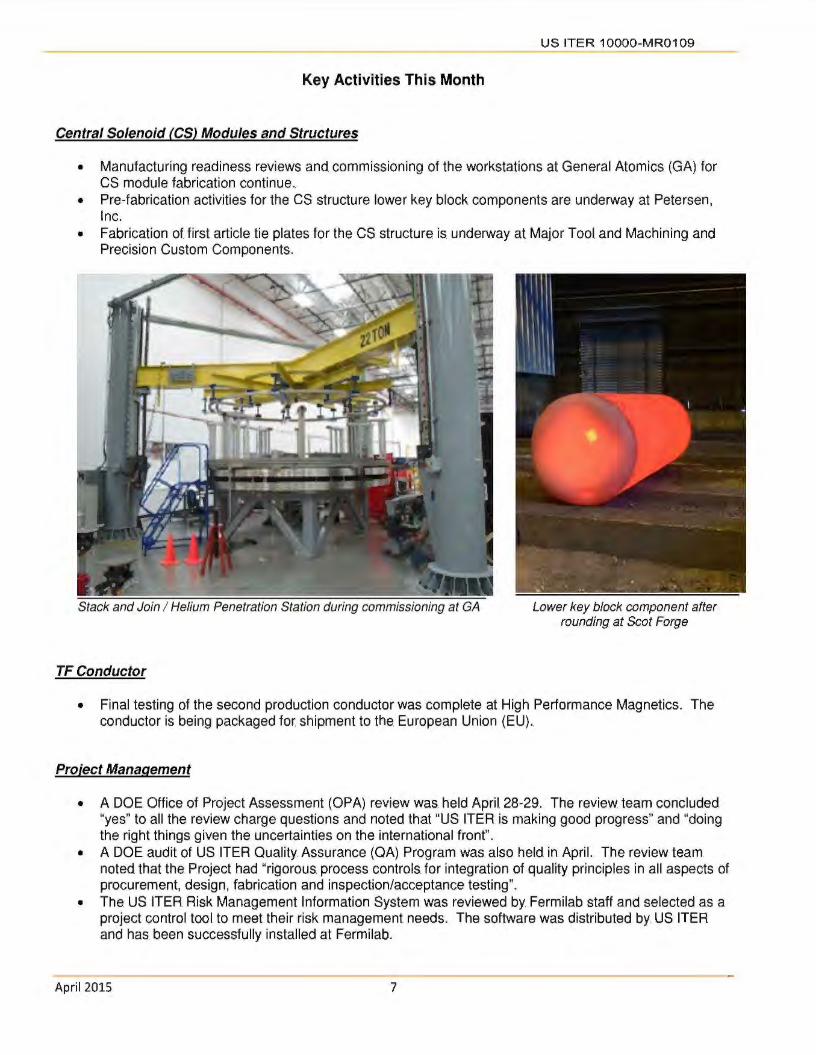
Central Solenoid f CSJ Modules and Structures
• Manufacturing readiness reviews and commissioning of the workstations at General Atomics (GA) for CS module fabrication continue.
• Pre-fabrication activities for the CS structure lower key block components are underway at Petersen, Inc.
• Fabrication of first article tie plates for the CS structure is underway at Major Tool and Machining and Precision Custom Components.
Stack and Join I Helium Penetration Station during commissioning at GA
TF Conductor
Lower key block component after rounding at Scot Forge
• Final testing of the second production conductor was complete at High Performance Magnetics. The conductor is being packaged for shipment to the. European Union (EU) ..
Project Management
• A DOE Office of Project Assessment (OPA) review was. held April 28-29. The review. team concluded "yes" to all the review charge questions and noted that "US ITER is making good progress" and "doing the right things given the uncertainties on the international front".
• A DOE audit of US ITER Quality Assurance (QA) Program was also held in April. The review team noted that the Project had "rigorous. process controls. for integration of quality principles in all aspects of procurement, design, fabrication and inspection/acceptance testing".
• The US ITER Risk Management Information System was reviewed by Fermilab staff and selected as a project control tool. to meet their risk management needs. The software was distributed by US ITER and has been successfully installed at Fermilab.
April 2015 7
US ITER 1OOOO-MR0109
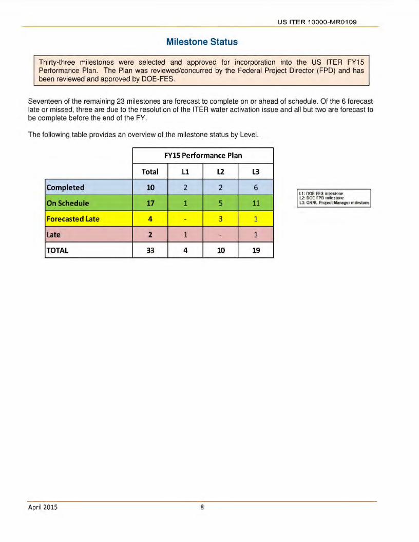
Milestone Status
Thirty-three milestones were selected and approved for incorporation into the US ITER FY15 Performance Plan. The Plan was reviewed/concurred by the Federal Project Director (FPO) and has been reviewed and approved by DOE-FES.
Seventeen of the remaining 23 milestones are forecast to complete on or ahead of schedule. Of the 6 forecast late or missed, three are due to the resolution of the ITER water activation issue and all but two are forecast to be complete before the end of the FY.
The following table provides an overview of the milestone status by Level.
FYlS Performance Plan
Total Ll L2 L3
Completed 10 2 2 6
On Schedule 17 1 5 11
Forecasted Late 4 - 3 1
Late 2 1 - 1
TOTAL 33 4 10 19
April 2015 8
L1: DOE FES milestone L2: DOE FPO milestone LJ: ORNL Project Manager milestone
CONTENTS
WBS 1.1.1 Magnet Systems - Oak Ridge National Laboratory (ORNL) Central Solenoid (CS) Modules, Structure, and Assembly Tooling Toroidal Field (TF) Coil Conductor
WBS 1.2. l Tokamak Cooling Water Systems (TCWS) - ORNL
WBS 1.3. l Vacuum Pumping & Fueling Systems - ORNL Roughing Pump (RP) Sets Vacuum Auxiliary Systems (VAS) Pellet Injection (Pl) Disruption Mitigation (DM)
US IT ER 1OOOO-M R0109
WBS 1.3.2 Tokamak Exhaust Processing (TEP) Savannah River National Laboratory (SRNL)
Page 10
Page 13
Page 15
Page 18
WBS 1.4.l Steady State Electrical. Network (SSEN) Princeton Plasma Physics Laboratory (PPPL) . Page 19
WBS 1.5.1.1 Ion Cyclotron Heating (ICH) Transmission Lines - ORNL
WBS 1.5.2.1 Electron Cyclotron Heating (ECH) Transmission Lines -ORNL
WBS 1.5.3 Diagnostics - PPPL
WBS 1.6 Project Support - ORNL Procurement Human Resources Quality Assurance
WBS 1.7 International Organization Support (Secondee and Cash Contributions)""". ORNL . .
Cash Payments Secondees/Employees Total Credit Earned
WBS 1.8 Supplemental Task Agreements (TAs) .
WBS 1.9 Instrumentation and Controls
Appendix A - US ITER Project Schedule
Appendix B - Project Change Requests processed this month
Appendix C - Level 3 (Project Manager) FY15 Milestones
April 2015 9
Page 20
Page 21
Page 22
Page 23
Page 24
Page 26
Page 27
Page 28
Page 29
Page 30

U S ITER 1OOOO-MR01 09
WBS 1.1.1 Magnet Systems - Oak Ridge National Laboratory (ORNL)
Central Solenoid (CS) Modules and Structure - Required for ITER 1 st Plasma
The US is responsible for the CS magnet, including design, R&D, and fabrication of six CS modules (coils) and a spare module using supplied cable-in-conduit superconducting conductor (from JA), the vertical. precompression structure, Assembly Tooling (AT), bus extensions, and cooling connections.
The CS serves as the backbone of the ITER magnet system. The CS induces the majority of the magnetic flux change needed to initiate the plasma, generate the plasma current, and maintain this current during the burn time.
General Atomics (GA) in San Diego, California, has. been awarded a major contract to. fabricate the modules of the CS.
Preparations for CS Modules , CS Structure and Assembly Tooling fabrication continue
WBS 1.1 .1.1 - CS Modules
The first manufacturing readiness review (MRR) for Station 3 (joint and terminal prep) was held and processing of the mock-up coil at this station has begun. Commissioning activities continue for Station 4 (stack and join and helium penetrations). A splice joint has been welded and leak checked. The
CS Modules
Begin winding the first central solenoid module
Conduct Turn Insulation MRR
1
2
commissioning coil has been sent to the reaction heat treatment station (Station 5). Once the commissioning work is completed at the reaction heat treatment station, the coil can be used for the MRR. of Station 6,. Turn Insulation (a Level 2. Performance Plan milestone).
14-Apr-15 23-Mar-15 A
02-Jul-15 24-Aug-15
r =Completed TI On-Schedule ---1.. ~Forecast to Miss pp Date n =Missed pp Date
WBS 1.1 .1.2 - CS Structures
Scot Forge's new recipe for heat treatment and solution anneal appears to have solved the grain size issue. The most recent forging passed the intergranular corrosion test and the grain size. measurement meets the specification requirement of ASME #4 .. Samples will. be. sent to National. High Magnetic Field Laboratory (NHMFL) for 4K testing but previous forging samples have passed with significant margin.
Pre-fabrication activities continued at Petersen, Inc. for manufacturing the lower key block components. Petersen's lower key block assembly quality plan and manufacturing and inspection plan (MIP) were approved by the International Organization (10).
April 2015 10
Two fabricators, Major Tool. and Machine and Precision Custom Components (PCC), are now underway with the fabrication of first article outer tie plates . . Major Tool and Machine. is. contracted to. produce two first article one piece outer tie plates. One of Major Tool's tie plates will. be. machined from a forging produced by Kind GmbH, in Gummersbach, Germany. The second Major Tool tie plate will be machined from a forging produced by Scot Forge in Spring Grove, IL.
A PCC Quality Plan (QP) has been submitted and approved. A weld procedure plan was submitted addressing the weld qualification for welding cooling pipe to the tie plate. PCC submitted a Manufacturing

and Inspection Plan (MIP) which is under review at the US ITER Project Office (USIPO).
A Request for Proposal (RFP) was issued for the next major CS structures procurement. This. package titled "CS Structure - Upper Components" contains
CS Structures
US ITER 1OOOO-MR0109
all of the components at the top of the CS structure. Proposals have been received and evaluated, requests for clarifications have. been sent to the. bidders.
MS Performance Forecast Milestone Description l
1 Pl
0 0 Comments
eve an ate ate ----=Completed =On-Schedule
WBS 1.1 .1.4 - CS Assembly Tooling (AT)
Procurement placed the. Assembly Platform solicitation and associated documents on a Contracts website on March 20, 2015, and sent an email announcing the Solicitation is posted along with the
=Forecast to Miss PP Date • =Missed PP Date 1
closing date. Questions were submitted by vendors throughout the month, which were answered and provided in the form of amendments to the solicitation.
Toroidal Field (TF) Coil Conductor - Required for ITER 151 Plasma
The US will contribute 8% of the TF coil conductors. The 10 is responsible for the conductor design which is released for fabrication. JA, EU, RF, KO, and CN are also contributing TF conductor.
The 18 TF coils produce a magnetic field around the ITER tokamak torus to confine the plasma particles. The US is responsible. for enough conductors to wind slightly over one TF coil..
The coils will be made of cable-in-conduit superconductors, in which a bundle of superconducting strands is cabled together, compacted into a stainless steel conduit,. and cooled by supercritical helium.
Luvata Waterbury (Waterbury, Connecticut) and Oxford Superconducting Technologies (Carteret, New Jersey) have been awarded major contracts to produce TF strand. New England Wire Technologies (Lisbon, New Hampshire) received the contract for cabling the strand and High Performance Magnetics (Tallahassee, Florida) will perform the. conductor integration/jacketing.
Fabrication of TF Conductor continues
WBS 1.1.1.3 - TF Coil Conductor
Final testing of the second Oxford (OST} production conductor (OST B) was completed at High Performance Magnetics (HPM). The conductor has been aligned and flipped, and is. being packaged for
April 2015 11
shipment to the EU. Jacket assembly for the third OST production conductor (OST C) was started. At NEWT, 4th and 5 th stage cabling of 11 Om active cable is delayed until June due to delays with the new payoff tension monitoring system.

U S ITER 1OOOO-MR0 109
A view of OST B production conductor at High Performance Magnetics after alignment and flipping
TF Conductors
Packaged and ready to ship first 760m conductor to EU 1 10-Jan-15 20-0ct-14A
Packaged and ready to ship Luvata 100m to EU 2 17-May-15 12-Mar-15 A
2nd 760m Conductor packaged 2 22-Sep-15 01-Jul-15
I [=Completed =-=On-Schedule ] =Forecast to Miss PP Date • =Missed PP Date
April 2015 12.

US ITER 1OOOO-MR0109
WBS 1.2.1 Tokamak Cooling Water Systems (TCWS) - ORNL
TCWS- Portions of the system required for ITER 1 st Plasma
The US is responsible for the design, engineering, and procurement of TCWS.
ITER's fusion power will reach 500 MW during the deuterium-tritium inductive plasma operation with an energy input of only 50 MW, yielding an energy multiplication factor of 10. Heat will be transferred by the TCWS from client systems to the environment through the secondary cooling system. TCWS is designed to cool client systems, such as. the. first wall/blanket, vacuum vessel, divertor,. and neutral. beam injector (NBI) .. Additional operations include baking of in-vessel components, chemical control of water provided to client systems, draining and drying for maintenance, and leak detection/localization.
The TCWS interfaces with the majority of ITER systems, including the secondary cooling system, which rejects this. heat to the environment. Plasma operations are. inherently. safe because a functioning cooling water system is not required to ensure safe shutdown.
System Design and Fabrication of the remaining three (of five) Drain Tanks continue
Design
Resolution of the high gamma radiation doses and fast neutrons continues to be a major focus of TCWS personnel from the 10 and US ITER. The 10 Director General concurred with the technical team recommendation to route. piping between the bioshield and the cryostat to shield activated water below Level 3 in Building 11. This decision, during a
Unique ITER Team (UIT) Meeting, coupled with the decision made during the Design Integration Review on March 20, 2015, reduces personnel and
electronics. and instrumentation dose. rates. significantly. Based on this decision, the US/10 TCWS team identified design activities needed to close Project Change Request (PCR-662) and meet F4E demands for component load data to support the building design schedule. Planning began for a TCWS Simplified Design Review to recover the TCWS design status to the final design level, which had been achieved before the activated water issue was identified.
Progress continued on meeting the DOE Performance Plan milestone: "Develop a resource
loaded schedule for completion of the final design, incorporating the design solution for the gamma
April 2015 13
radiation issue." This milestone. is being accomplished by establishing a Design Plan to close PCR-662, ensuring that the 10 covers the cost of performing these activities, and linking the Design Plan schedule. activities to 10-TCWS Arrangement activities to establish the delay in the design. In addition, earned value (EVMS) reporting is corrected to include. only those. activities. that are. within the. original scope of the Arrangements.
Integrated Blanket,. Edge Localized Mode and Divertor (IBED) Primary Heat Transfer System (PHTS) piping and shielding 3D layout continues as authorized by PCR-662, with focus on the relocation of IBED PHTS equipment previously on Level L4 to Level L3 and the routing of piping in the space between the cryostat and the bioshield.
Progress was achieved on other portions of the TCWS design including optimization of the Vacuum Vessel Primary Heat Transfer System (VV PHTS) using Fathom fluid modelling. The previous VV
PHTS design removed 1 O MW while the current designed thermal. load has been determined to be 32 MW.

Fabrication of Piping
Proposals from various vendors for the Piping and Fittings Contract have been reviewed by the.10-
TCWS with technical expert advice from US ITER.
Fabrication of Drain Tanks
Normal Drain Tanks 2A (NDT2A) and 28 (NDT2B) arrived at the dock in Fos-sur-Mer, near Marseille, on April 26, 2015. Fabrication of the remaining tanks is nearing completion with preparation for transportation
I
US ITER 1OOOO-MR0109
expected by June 2015. The status as of late April is:
• Neutral Beam Injection Tank (NBl3) - Tensile testing and dye penetrant testing completed.
• Safety Drain Tank 1 A (SDT1 A) - Surface.
passivation is in progress.
• Safety Drain Tank 1 B (SDT1 B) - Skirt fit-up and root pass welding completed.
Drain tank arrival and off-loading at the port of Fos-sur-Mer, France
TCWS
Develop a resource-loaded schedule for completion of the Final Design,
incorporating the design solution. for. the gamma radiation issue.
IQ.Awards Framework contract for TCWS Pipings & Fittings
n= Completed 0 = On-Schedule
April 2015
2 31-May-15 29-May-15
2 31-Jul-15 20-0ct-15
I = Forecast to Miss PP Date • =Missed PP Date
14

US. IT ER 1OOOO-MR0109
WBS 1.3.1 Vacuum Pumping & Fueling Systems - ORNL
Roughing Pump Sets - A portion of the components required for ITER 1 st Plasma
The US wil l contribute 100% of the ITER roughing pumps.
The ITER tokamak, cryostat, and auxiliary vacuum chambers must be evacuated prior to and during operations. The roughing pump system exhausts the torus and NBI cryopumps, service vacuum, and. cryostat. This system will utilize a matrix of pump trains with various technologies to match. specific vacuum system requirements, including tritium-compatible backing pumps for torus and neutral beam cryopumps.
Support to the 10 for Conceptual Design continues
WBS 1.3.1.1 - Roughing Pump Sets
R&D
The Roughing Pump System (RPS) Conceptual design is the responsibility of the 10. A series of Task Agreements (TA)s to the US delineates the R&D support provided to the 10 by the US ITER Team.
The initial round of cryogenic viscous compressor (CVC) performance testing in the Spallation Neutron Source (SNS) cryogenic test facility (CTF) was successfully completed. The test data will be analyzed and plans for any equipment adjustments
and subsequent testing formulated over the next month.
The final test report on the performance testing of the tritium compatible prototype roots and screw pump will be issued mid-May. The test stand was disassembled and the components stored at ORNL. The 10 has subsequently expressed an interest in acquiring the test stand and is in the process of revising the TA. The pumps were packaged for shipment to the 10, which is now expected to occur in mid-May.
CVC Test Setup in SNS Cryogenic Test Facility
April 2015 15
US IT ER 1OOOO-MR0109
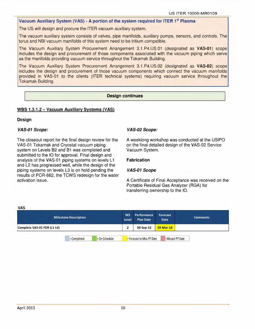
Vacuum Auxiliary System (VAS) - A portion of the system required for ITER 151 Plasma
The US will design and procure the ITER vacuum auxiliary system.
The vacuum auxiliary system consists of valves, pipe manifolds, auxiliary pumps, sensors, and controls. The torus and NBI vacuum manifolds of this system need to be tritium compatible.
The Vacuum Auxiliary System Procurement Arrangement 3.1.P4.US.01 (designated as VAS-01 ) scope includes the design and procurement of those components associated with the vacuum piping which serve as the manifolds providing vacuum service throughout the Tokamak Building.
The Vacuum Auxiliary System Procurement Arrangement 3.1.P4.US.02 (designated as VAS-02) scope includes the design and procurement of those vacuum components which connect the vacuum manifolds provided in VAS-Ol to the. clients (ITER technical systems) requiring vacuum service. throughout the Tokamak Building.
Design continues
WBS 1.3.1 .2 - Vacuum Auxiliary Systems (VAS)
Design
VAS-01 Scope:
The closeout report for the final design review for the VAS-01 Tokamak and Cryostat vacuum piping system on Levels B2 and B1 was completed and submitted to the 10 for approval. Final design and analysis of the VAS-01 piping systems on levels L 1 and L2 has progressed well, while the design of the piping systems on levels L3 is on hold pending the results of PCR-662, the TCWS redesign for the water activation issue.
VAS
lfCompleted _ __ ._= 0-'--n-·Schedule
April 2015 16
VAS-02 Scope:
A weeklong workshop was conducted at the USIPO on the final detailed design of the VAS-02 Service Vacuum System.
Fabrication
VAS-01 Scope
A Certificate of Final Acceptance was received on the Portable Residual Gas Analyzer (RGA) for transferring ownership to the 10 .
=Forecast to Miss PP O_ate ___ ..._=Missed PP Dai;"]
US ITER 1OOOO-MR0109.
Pellet Injector (Pl) System - A portion of the system required for building integration prior to ITER 1st
Plasma
The US will design and procure the Pl system.
Pl provides efficient core and edge fueling and will deliver hydrogen, deuterium, or a deuterium/tritium mixture as required by plasma operations. Delivering fuel pellets to the plasma edge mitigates ELM (edge localized mode) instabilities.
R&D. and Preliminary Design Activities continue
WBS 1.3.1.3 - Pellet Injection
The pellet injection flight tubes Preliminary Design Review (POR) is scheduled for late June. US ITER is reviewing the load analysis of the flight tubes and updating for the POR. The 10 is performing an electromagnetic (EM) analysis to determine the loads on the flight tubes due to EM transients (expected completion end of May). These loads are needed to complete the analysis of the flight tubes for the PDR.
Fabrication is nearing completion on the updated twin screw extruder . . Fabrication is scheduled to. complete in May with testing to resume in June.
An effort is underway to validate the pellet survivability through the ITER pellet flight tubes. A mockup of the ITER geometry of the high field side injection location was fabricated with initial testing performed. Results from the initial testing, although preliminary, show pellets are likely to survive up to speeds of - 300 mis, which is the nominal required speed for the ITER geometry. Testing will continue to fully characterize the flight tubes.
Disruption Mitigation - System not required for ITER 1 st Plasma
The US will contribute up to. a capped value for the Disruption Mitigation System (OMS). The system has two functions, 1) limiting the impacts of plasma current disruptions to the tokamak vacuum vessel, first wall blankets and other in-vessel components and, 2) suppressing the formation and deleterious effects of highenergy runaway electrons. Out of port plug installation of shattered pellet injection (SPI) units at four port locations that are designed to also function as massive gas injection (MGI) units is the current plan for the OMS. In addition, an option for an MGI unit within a port plug is included. This unit is to be designed to function during non-nuclear operations only to provide operational experience of a fast acting MGI unit close to the plasma.
Preliminary Design Activities continue
WBS 1.3.1.4 - Disruption Mitigation
A service panel designed to operate the test MGI valve over many repetitions was designed and is under fabrication. The panel will be used to monitor the gas pressures and to remotely operate the valve for extended durability testing . . Fabrication is expected to complete in June, with testing to resume afterwards.
Several options for testing an MGI valve in a high magnetic field are being explored. Facilities have been identified at Los Alamos National. Laboratory capable of performing the testing.
April 2015 17
Preliminary level modeling of a valve for an ITER SPI system has been completed. The valve is designed to operate in the challenging ITER environment while producing the necessary pellet speeds.
Significant design effort is being expended integrating the SPI design into the Upper Port Plugs in partnership with the Port Plug Integrators. As the area is very congested and used by several ITER groups, this effort is expected to continue for the foreseeable future.

U S ITER 1OOOO-MR01 09
WBS 1.3.2 Tokamak Exhaust Processing (TEP) - Savannah River National Laboratory (SRNL)
TEP - System not required for ITER 151 Plasma
The US is responsible for the Final Design (FD), fabrication, assembly, testing, and shipment of the TEP system.
ITER will require the processing of an unprecedented rate of hydrogen isotopes. To facilitate environmental responsibility and economic application of fusion technology, the reuse of hydrogen isotopes is vital. The. TEP system must separate the exhaust gases into a stream containing only hydrogen isotopes and a stream containing only. non-hydrogen gases. The implementation of the. TEP system will provide. a technically mature, robust, and cost-effective separation solution.
The TEP system consists of a series of filters, catalysts, and permeators (PM) to separate the hydrogen isotopes, which are then sent to an isotope separation system (furnished by the EU) to deliver deuterium and tritium for continuous reinjection into the reactor.
Support for Preliminary Design Activities continues
Preliminary design is the responsibility of the 10. A Task Agreement (TA) to the US delineates the part of the design to. be. performed by US ITER TEP Team. The team continued activities for the design studies for Subtask-2 of the TA (Functions, Requirements, Interfaces and Scenarios).
April 2015 18
Currently, the US TEP design team is approximately 35% complete with Subtask-2 TEP Process Studies. Results of the studies will remain as 'draft' until the. final input documentation is received by the 10 . Receipt of the final input from the 10 is currently scheduled in May.

U S ITER 1OOOO-MR01 09
WBS 1.4.1 Steady State Electrical Network (SSEN) - Princeton Plasma Physics Laboratory (PPPL)
SSEN - Hardware required for ITER 1 st Plasma
The US contributes 75% of the. equipment required for the SSEN, excluding cables and emergency power .. The. EU contributes the remaining equipment and is also responsible for the design and installation of the system as well as all cabling and all emergency (diesel generator) power systems.
The SSEN is an alternating current (AC) power substation and distribution system that supplies electrical power to all ITER conventional systems and facilities. A separate system delivers power to the pulsed systems, including the magnet and heating power supplies.
The. SSEN is rated at 120 MW and is similar to the auxiliary power distribution system in a nuclear fission power plant, except that it is about twice the size. The equipment to be contributed by the US is typical of a large AC power distribution system, consisting of transformers and switchgear at the high-voltage (400 kV) and medium-voltage (22 kV) levels.
Hardware Procurements and Shipments continue
Twelve of 16 contracts have been signed and/or executed. Procurement of. another contract is. underway and the. remaining 3 are on hold. A total of, 15 of 31 the shipments have been completed. Status of the 16 SSEN procurements is as follows:
• The HV Substation Transformers. l(b)(5) Industries, Ulsan, Korea) Unit #2 11._a_s_b_e_e_n __ __, (b )(5)
• The 6.6kV Switchgear l(b)(5) (b)(5)
• The Power Transformersl(b)(5) (b)(5)
I
• US ITER authorized the procurement of the Reactive Power Compensators in FY15 so a Subcontract Proposal Evaluation Board (SPEB) was formed and preparations started on the. Request for Proposal (RFP) package.
I
• The HV Circuit Breakers, HV Switches, HV Current Transformers, HV Potential Transformers, HV Surge Arresters, HV Substation Hardware, Earthing Resistors, and the HV Control & Protection have all been delivered to the ITER site. The final Delivery Reports are being processed for these items, after which ITER credit will be requested.
• DC Distribution,. UPS,. and LV Distribution & Subdistribution Panels procurement activities are postponed due to funding constraints.
• The 22kV Switch ear (b)(5) (b)(5)
SSEN
IPL> Delivery of HV Substation Transformers (Lot 4) by US-DA. to ITER Site 1 27-May-15 12-M ay-15
Packaged and ready to. ship - 6.6kV Switchgear (Lot 1) 2 28-Jun-15 01-Jun-15
Packaged and ready. to. ship - 22kV Switchgear (Lot 2). 2 16-Jul-15 06-May-15
D = Completed • =On-Schedule =Forecast to Miss PP Date • =Missed PP Date
April 2015 19

U S ITER 1OOOO-MR01 09
WBS 1.5.1.1 Ion Cyclotron Heating (ICH) Transmission Lines - ORNL
IC Transmission Lines- A portion of the system is required for building integration prior to ITER 1st Plasma
The US is responsible for the IC transmission lines, including R&D, design, fabrication, and interfaces. The 10 is responsible for installing the IC transmission lines.
The IC system heats the ions in the plasma with a high-intensity beam of electromagnetic (EM) radiation. Generators produce high-power radio frequency waves that are carried along multiple transmission lines to antennas located in the vacuum vessel, sending the waves into the plasma. The US IC transmission lines will provide efficient power transfer from 40- 55 MHz radio frequency sources to the plasma heating antennas. The system will include coaxial transmission lines and a matching/tuning system to minimize power transfer losses. The pressurized lines can transmit up to 6 MW per line. In total, approximately 1.5 km of line connects 8 sources to 16 antenna feeds, with 14 types of transmission line and matching system components. The main interfaces include sources, launchers, buildings, port cells, and water cooling. The short coaxial line also provides secondary tritium confinement.
Preliminary Design Activities continue
Design kickoff meetings were held with the vendor teams that are in the first phase of developing designs of 3-meter-long stub tuners .. These. tuners. are an important component of the ICH tuning/matching system . .
The radiofrequency resonant line test stand was used to. perform multiple successful, 1-hour pulse. length, high-voltage tests on a 4-port ICH
April 2015 20
transmission line switch test article. Similar switches will be installed in the ITER Radio Frequency (RF) building, where. they allow the. flexibility to. connect each of the nine RF transmitters to power loads for testing or to. the. main transmission lines for plasma heating.

U S ITER 1OOOO-MR01 09
WBS 1.5.2.1 Electron Cyclotron Heating {ECH) Transmission Lines - ORNL
EC Transmission Lines - A portion of the system is required for ITER 1 st Plasma
The US is responsible for the EC transmission lines, including R&D, design, fabrication, and interfaces. The 10 is responsible for installing the EC transmission lines.
The EC system heats the electrons in the plasma with a high-intensity beam of electromagnetic radiation. This system is also used to deposit heat in very specific places in the plasma. Power will be provided by powerful , high-frequency gyrotrons. The US transmission line design will provide efficient power transfer from 170 GHz gyrotron sources to plasma heating power launchers (20 MW).
The transmission lines feature multiple lines of evacuated aluminum waveguides with internal corrugations that can transmit 1.5 MW per line for 3000 seconds, while minimizing power transfer losses to s 10%. Approximately 4 km of transmission line will be part of this system, connecting 24 sources to 56. feeds with 1 O types of waveguide components. The main interfaces include sources, launchers, buildings, port cells, water cooling, and auxiliary vacuum. The waveguide also provides secondary tritium confinement.
Final Design Activities. continue.
A pre-bid meeting was held with four potential bidders for a Basic Ordering Agreement (BOA) for "Process Development and Manufacture of 4.2 m Waveguide and Associated Components". The initial task for vendors will be to evaluate manufacturing options ..
April 2015 21
A deviation request for the ECH credit allocation schedule (CAS) revision was approved by the 10 and incorporated into the. project scheme. The. request included the revised US schedule for design reviews and an optimized sequence for the hardware delivery packages.
US ITER 1OOOO-MR01 09
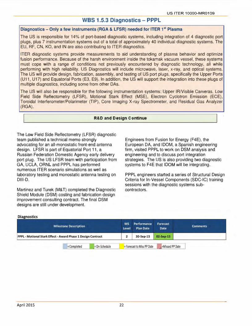
WBS 1.5.3 Diagnostics - PPPL
Diagnostics - Only a few instruments (RGA & LFSR) needed for ITER 1 st Plasma
The US is responsible for 14% of port-based diagnostic systems, including integration of 4 diagnostic port plugs, plus 7 instrumentation systems out of a total of approximately 40 individual diagnostic systems. The EU, RF, CN, KO, and IN are also contributing to ITER diagnostics.
ITER diagnostic systems provide measurements to aid understanding of plasma behavior and optimize fusion performance. Because of the harsh environment inside the tokamak vacuum vessel, these systems must cope with a range of conditions not previously encountered by diagnostic technology, all while performing with high reliability. US Diagnostics will include microwave, laser, x-ray, and optical systems. The US will provide design, fabrication, assembly, and testing of US port plugs, specifically the Upper Ports (U11 , U17) and Equatorial Ports (E3, E9). In addition, the US will support the integration into these plugs of multiple diagnostics, including some from other DAs.
The US will also be responsible for the following instrumentation systems: Upper IA/Visible Cameras, Low Field Side Reflectometry (LFSR), Motional Stark Effect (MSE), Electron Cyclotron Emission (ECE), Toroidal Interferometer/Polarimeter (TIP), Core Imaging X-ray Spectrometer, and Residual Gas Analyzer (RGA).
R&D and Design Continue
The Low Field Side Reflectometry (LFSR) diagnostic team published a technical memo strongly advocating for an all-monostatic front-end antenna design. LFSR is part of Equatorial Port 11 , a Russian Federation Domestic Agency early delivery port plug. The US LFSR team with participation from GA, UCLA, ORNL and PPPL has performed numerous ITER scenario simulations as well as laboratory testing and monostatic antenna testing on Dlll-0.
Martinez and Turek (M&T) completed the Diagnostic Shield Module (DSM) costing and fabrication design improvement consulting contract. The final DSM designs are still under development.
Diagnostics
Engineers from Fusion for Energy (F4E), the European DA, and IDOM, a Spanish engineering firm, visited PPPL to work on DSM analysis and engineering and to discuss port integration strategies. The US is also providing two diagnostic systems to F4E that IDOM will be integrating.
PPPL engineers started a series of Structural Design. Criteria for In-Vessel Components (SDC-IC) training sessions with the diagnostic systems subcontractors.
MS Performance Forecast Milestone Description Level Plan Date Date Comments
--- -I = On·Schedule =Forecast to Miss PP Date l =Missed PP Date ]
April 2015 22
US ITER 1OOOO-MR0109
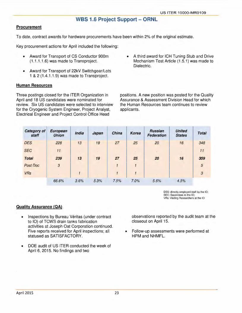
WBS 1.6 Project Support - ORNL Procurement
To date, contract awards for hardware procurements have been within 2% of the original estimate.
Key procurement actions for Apri l included the following:
• Award for Transport of CS Conductor 900m (1.1.1.1.6) was made to Transproject.
• Award for Transport of 22kV Switchgear/Lots 1 & 2 (1.4.1.1.9) was made to Transproject.
Human Resources
Three postings closed for the ITER Organization in April and 18 US candidates were nominated for review. Six US candidates were selected to interview for the Cryogenic System Engineer, Project Analyst, Electrical Engineer and Project Control Office Head
• A third award for ICH Tuning Stub and Drive Mechanism Test Article (1.5.1) was made to Dielectric.
positions. A new position was posted for the Quality Assurance & Assessment Division Head for which the Human Resources team continues to review applicants.
Category of European India Japan China Korea Russian United Total s taff Union Federation States
DES 228 13 19
SEC 11.
Total 239 13 19
Post Doc 3
VRs 1
66.6% 3.6% 5.3%
Quality Assurance (QA) .
• Inspections by Bureau Veritas (under contract to 10) of TCWS drain tanks fabrication activities at Joseph Oat Corporation continued. Five reports received for April inspections; all statused as SATISFACTORY.
• DOE audit of. US ITER conducted the week of April 6, 2015. No findings and two
April 2015
27
27
1
7.5%
23
25 20 16 348
11.
25 20 16 359
5
1 3
7.0% 5.6% 4.5%
DES:. directly employed staff by the 10 ; SEC:. Secondees to. the 10; VRs: Visitln9 Researchers. at the 10
observations reported by the audit team at the closeout on April 15.
• Follow-up assessments were performed at HPM and NHMFL.

US ITER 1OOOO-MR0109.
WBS 1.7 International Organization Support
(Secondees and Cash Contributions) - ORNL
Per the. JIA,. the US is. obligated to. contribute 9.09% of the value estimate of the construction of ITER. The contributions are measured in ITER kilo Units of Account (klUA),. which. has been used by ITER for many years; 1 klUA equals $1 MUS dollars (January 1989). The US commitment, 424.618. klUA, includes hardware fabricated/procured by the US, cash for installation and commissioning, staff (secondees or cash for direct employees), and cash. for R&D directed by the 10.
The. US can also receive credit (klUAs) for performing additional work through approved Task Agreements (TAs). The. US will. cover its share ofthe cash. contributions. through cash. payments in current year Euros upon request by the 10. Euros are. purchased with. current year. dollars using the current exchange rate when the. payment is due. To establish. the klUA value of annual cash contributions, the Euros. are de-escalated to. Euros (January 1989) using proven inflation rates, and then converted to. millions of dollars (January 1989) to yield klUA.
Note: the tables below reflect a new decision not to grant credit for contributions. to the IQ prior to CY 2007 .. The Cash Payments Table contains the 2006 cash contribution but the credit does not contain this 2006 value.
Cash Payments
Calendar Budgeted € Paid € Paid $
Remaining Year Obli~ation €
2006 409,000 € 409,000 € $528,918.80 0
2007 3,985,000 € 3,985,026.06 € $5,463,23 1. 76 0
2009 15,689,630.70 € 15,689,604.64 € $21,102,518.24 0
2010 9,567,409 € 9,567,409 € $13,552,234.85 0
2010 1,577,433 € 1,577,433 € $2,018,010.04 0
Sunnlemental 2011 Advance
9,132,173 € 9,132,173 € $11 ,650,826.31 0 Payment
2012 9,450,359 € 9,450,359 € $12,133,315.92 0
2013 17,672,925 € 17 ,672,925 € $23,975,973.67 0
2014 14,885,339 € 14,885,339 € $20,280,343.91 0
2015 13,741,328 € 13,741,328 € $14,827,218.12 0
Cumulative 96,110,596.70€ 96,1 10,596. 70€ $125,532,591.62 0
Estimated Credit Earned to date: 59.284 kIUA
Average Exchange Rate realized for cash paid = 1.306
April 2015 24

U S ITER 1OOOO-MR01 09.
Secondees/Employees
U.S. Secondees Credit Earned: 1.531 kIUAs Current Number of Secondees: 0
U.S. Direct Hires Current Number of U.S. Direct Hires: 37
Total Credit Earned (- 20% of total planned)
Total Planned Actual Credit Change In Remaining Allocation Credit klUA Received klUA Actual Credit klUA
1.531 1.531
207.520 11.730 195.790
15.193 12.685 2.508
202.986 59.284 143.702
427.230 85.230 342.000
2007 2008 2009 2010 2011 2012 2013 Cash 2.711 0 10.138 13.063 0 5.835 10.645 Secondees .629 174 177 .246 .105 0 0 TAs 0 JOO .048 2.284 4.611 2.497 1-939 PAs 0 0 0 2.500 0 5.850 0 Total 3.340 .574 10.463 18.093 4.716 14.182 12.486
2014 2015 Total Cash 8.842 8.050 59184 Secondees 0 0 1.531 TAs 1.006 0 12.685 PAs 3.380 0 11.730 Total 13.228 8.050 85.230
April 2015. 25

U S. ITER 1OOOO-MR01 09
WBS 1.8 Supplemental Task Agreements (TA) with the 10
Task Agreements currently in-progress
Credit Credit Received
Amount to Date Expected TA # Description Agency US Contact (klUA) (klUA) TA Start Finish
TA·FC·IPT·US·RP·01 Validation of lv'echanical Roughing. Concepts US·IPO M. Hechler, Larry.
0.435 01/02/2011 06/10/2015 Bavlor
C.74 TD 21 FU Neutronics Analysis Support for ITER ORNL/U,of Wisc. B. Nelson I
0.318 09/0112014 07/10/2015 r..t:lhamed. Sa wan
TA-FC-fPT-US·RP-02 rTER Roughing System Cryogenic Viscous Flow.
US·IPO M. Hechler, Larry
0.267 01/02/201 1 09/08/2015 Comoressor Develooment Savior
C.55 TD 36 FU Generic Diagnostic First Wall.Preliminary.and Final Des ign PPPL Wayne. Steffey,
1.237 0.322 09/01/2012 03/31/2016 Doua Loesser
C 18 TD 35.FU De11etopment ol ITER class. Pellet Injector US·IPO D. Rasmussen 0 10/01/2008 07/28/2016
TA-FC-IPT-US· 13·01 Preliminary Design Tasks.associated with. PBS 32.EP Plant
SRNL Bernice. Rogers 0.571 10117/2013 06/30/2017 S.slom
TA·FC-IPT-US·RP-03 Validation ol Piston. Pump.for fTER Roughing.System US·IPO Dave.Rasmussen,
0.002 10/17/2012 11/30/2017 Larry.Baylor
Total klUA .2.830 .. 0.322 Approx .. $ $ ,6,248,000 $ 711,000
April 2015. 26

US ITER 1OOOO-MR0109
WBS 1.9 Instrumentation and Controls (l&C)
Centralized Instrumentation and Controls Support. Required for ITER 1 st Plasma
The. US is responsible to provide l&C for all Procurement Arrangements (except Magnets and SSEN). Work scope includes:. conceptual, preliminary, and final. l&C design; l&C software design; l&C hardware and software procurement; l&C equipment fabrication ; and l&C qualification and testing .. The WBS 1.9 work scope definition includes the majority of US DA l&C work scope, but the details will be defined on a WBS-byWBS basis. (e.g. Some. major equipment procurements will include l&C content; some engineering services contracts such as for Diagnostics will. include l&C content; etc. so this. work scope will. remain in the other WBS areas) .. Benefits of a centralized l&C support include: sharing of. specialized engineering. resources; the promotion of standard designs, standard software components, and standard equipment; and the provision of commonly-required services including technical and qualification support.
Assembling l&C team and starting Conceptual and Preliminary Designs
WBS 1.9.2. t TCWS. l&C
The initial analysis. was. completed of. expected instruments that will be exposed to high level of neutron flux .. This. will help determine if. passive equivalents are available as a mitigation. Six instruments have been identified that cannot be. exposed to neutron or gamma radiation above alert thresholds.
April 2015 27
WBS. 1.9.3.3. Pellet Injector l&C
An initial. assessment of the updated cost estimate. was conducted.
WBS 1.9.3.2. Vacuum Auxiliary Systems l&C.
An updated cost estimate for VAS.02 l&C was developed.

Appendix A
US ITER Project Schedule (L 1/L2 Milestones)
US ITER 1OOOO-MR0109.
Shown below is. the. summary schedule. for the. Project's planned activities. in FY15 .. The. schedule is. aligned with the revised funding provided by the DOE Office of Fusion Energy Science which assumes funding of $150M in FY15.and $150M in FY16.
FY15
Needed for :ti.as. Technical System 1" Plasma
01 02 0 3 Q4 I
I I I I "111"7 1"7
E 1.1.1.1 Central Solenoid GI c;; ~ 1.1.1.3 Toroidal Field Conductor
- I
I I I . ~ I - I SJ. ~ -I
I I I I I I I I I
1.2.1 Tokamak Cooling I I SJ. s::J- I
" I " Water System I I I
I I I 1.3.1.1 Roughing Pumps
I I I 1.3.1.2 Vacuum Auxiliary
Systems
VI E 1.3.1.3 Pellet Injection GI c 0 Q. 1.4.1 Steady State. Electrical E 0 Network ()
I I I '\ I
I I I I I I
' I
I I
~ I I
' I
I I I 1.5.1 ICH Transmission Lines
I ' I
I I I
1.5.2 ECH Transmission Lines I I I
1.5.3 Diagnostics I I I '\
I I I I I I
~ I I I
c 1.3.1.4 Disruption Mitigation tJ)
·c;; GI Q 1.3.2 Tokamak Exhaust
I I I
I I I I I I
~ - Processing•
·credlred Task Agreement KEY
c:=J D~~ign tZZJ Design and Fabrication c::J Fabrication
PP Miiestones: 'Jon-time 'J Forecasted Late 'JLate V complete
April 2015 28

US ITER 1OOOO-MR0109
Appendix B
Project Change Requests processed this month
There. were five. Project Change Requests (PCRs) processed in April. All PCRs were reviewed against the contingency guidance to determine the applicable usage of Management Reserve and DOE-held contingency.
All PCRs were Level 3 (Project) .
l111>act ($M)
Month . Management DOE
PCR# Description WBS Reserve. Contingency
Apr CS-2015-16 Additional.4K Mechanical Properties Testing at NHMFL 1.1.1.1 (0.037)
Apr CT-2015-13 Move Diagnostics Design. Support Budget to new L4 WBS 1.9.7 .. . .. ....• . -
Apr US-2015-13 WBS Dictionary Update - change project from MIE to. Line Item 1 .. -Apr CS-2015-17 Replanof.General Atomics BCWS 1.1.1.1 . . ..
Apr CW-2015-9 Drain Tanks Budget Real located 1.2.1 -
April 2015 29
US ITER 1OOOO-MR01 09
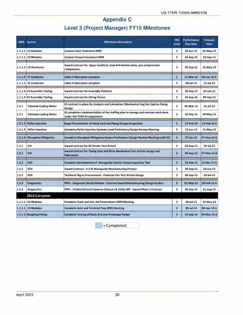
Appendix C
Level 3 (Project Manager) FV15 Milestones
1.1.1.1 . CS. Modules Conduct Heat Treatment M RR 3 02-Jun-15 26-May-15
1.1.1.1 . CS. Modules Conduct Ground Insulation. MRR 3 24-Sep-15 23-Sep-15
1.1.1.2 . CS. Structures Award contract for .. Upper key block, load distribution plate, pre-compression
3 30-Sep-15 15-May-15 compone nts .
1.1.1.3 TF. Conductor Cable 3 fabrication complete 3 11-Mar-15 09-Jan-15 A
1.1.1.3 TF. Conductor Cable 4 fabrication complete 3 08-Jul-15 31-Jul-15
1.1.1.4 CS Assembly Tooling Award contract for Assembly Platform 3 30-Sep-15 24-Jun-15
1.1.1.4 CS Assembly. Tooling Award contract for. lifting Fixture 3 30-Sep-15 09-Sep-15
1.2.1 Tokamak Cooling Water 10. contract. in-place for Analysis and Calculation (Mechanical. Eng) for Captive Piping
3 04-Mar-15 31-Jul-15 Design
1.2.1 Tokamak Cooling Wate r 10 completes implementation of the staffing plan to manage and oversee. work done
3 30-Sep-15 29-May-15 under the TCWS Arrangements
1.3.1.3 . Pellet Injection Begin Procurement of Initial. Cask and. Piping Design Integration 3 27-Feb-15 13-Feb-15.A
1.3.1.3 . Pellet Injection Complete. Pellet Injection Systems Level. Preliminary Design Review Meeting 3 13-Jun-15 11-May-15
1.3.1.4 Disruption Mitigation Complete Dis ruption Mitigation System Prell ml nary Design Review Meeting (with 10) 3 07-Jan-15 07-Nov-14A
1.S.1 .ICH Award contract for. DC Breaks Test Article 3 02-Sep-lS 29-Jul-lS
1.5.1 ICH Award contract for Tuning Stub and Drive. Mechanism Test Article. Design and
3 30-Sep-lS 27-Mar-lS A Fabrication
1.S.2 ECH Complete. Developme nt of Waveguide Inte rior Vis ual Inspection Tool 3 25-Feb-15 15-Dec-14. A
1.5.2 .ECH Award Contract - 4 .2 M Waveguide. Manufacturing Process 3 30-Sep-15 22-Jun-15
1.5.2 .ECH Technical. Pkg to. Procurement. - Polarizer. Pair. Test. Article. Design 3 30-Sep-15 20-Jul-15
1.5.3 . Diagnostics PPPL - Diagnostic Shield. Module -. Contract Award Manufacturing Design Studies 3 01-May-15 20-Feb-15A
1.5.3 . Diagnost ics PPPL-. Visible/Infrared Cameras (Sensors & DAQ) UPP. - Award Phase 2 Contract 3 30-Sep-15 31-Aug-15
1.1.1.1 CS Modules Complete. Stack and Join,. He Penetrations MRR Meeting 3 30-Jul-14 15-May-15
1.1.1.1 .CS Modules Complete Joint and Te rminal. Prep MRR Meeting 3 30-Jul-14 08-Apr-15 A
1.3.1.1 Roughing Pumps Complete Testing of Roots. & Screw. Prototype Pumps 3 23-Sep-14 09-Mar-15.A
= Completed
April 2015. 30

Department of Energy ORNL Site Office
P. 0 . Box 2008 Oak Ridge, Tennessee 37831-6269
Julyl , 2015
MEMORANDUM FOR DISTRIBUTION "- (')~ ~(____
FROM: DAVID K. ARAKAWA bLY FEDERAL PROJECT DIRECTOR U.S. CONTRIBUTIONS TO ITER PROJECT
SUBJECT: U.S. ITER PROJECT MONTHLY REPORT- MAY 2015
Attached for your information is a copy of the project's Monthly Report for May 2015. Cumulative cost and schedule earned value performance indices for the month were 0.99 and 1.0, respectively. Thirteen Project Change Requests (PCRs) were processed during May and
these PCRs are summarized in Appendix B of this report. There was one Level 1 milestone (Delivery of High Voltage [HV] Substation Transformers [Lot 4) by US-DA to ITER Site) and one Level 3 milestone (Complete Pellet Injection Systems Level Preliminary Design Review Meeting),
which were completed early during May.
Key activities in May included the continued installation of equipment, manufacturing readiness reviews, and commissioning activities for the remaining Central Solenoid (CS) fabrication
stations at General Atomics. Fabrication of first article CS Structure tie plates continued, as well as pre-fabrication activities for CS Structure Lower Key Block components. In addition to the deliveries of HV transformers, two of the transformers were installed at the ITER site,
representing the first installation of key components from any Domestic Agency. Fabrication of Toroidal Field Conductor and Tokamak Cooling Water System Drain Tanks continued. Research and development and design activities continued for the Pellet Injection System, the Disruption
Mitigation System, Diagnostics, and Ion Cyclotron and Electron Cyclotron Transmission Lines.
If there are any questions or additional information is required, please contact me at (865) 576-2667 or David Myers at (865) 576-5629.

DISTRIBUTION -2-
SUBJECT: U.S. ITER PROJECT MONTHLY REPORT-MAY 2015
Attachment
Distribution w/attachment: J. Steve Binkley, SC-21 Kin K. Chao, SC-28 Casey R. Clark, SC-28 Patricia M. Dehmer, SC-2 Michael l. Knotek, S-4 Joseph J. May, SC-24.1 Stephen W. Meador, SC-28 Edward J. Stevens, SC-24.2 Edmund J. Synakowski, SC-24 Sotirios Thomas, S-4 Thomas J. Vanek, SC-24.1 Brian D. Huizenga, MA-50 Scott Cannon, NNSA Jeffrey Makiel, PPPL David K. Arakawa, SC-OSO Michele G. Branton, SC-OSO William C. Cahill, SC-0$0 Daniel K. Hoag, SC-OSO Johnny 0. Moore, SC-OSO
Distribution w/o attachment: Dina 0. Clark, ORNL Suzanne A. Herron, ORNL Ned R. Sauthoff, ORNL
July 1, 2015

d/~ us
iter
us Contributions to ITER
The first plant components, two HV substation transformers procured by the US, were installed at the ITER site on May 21, 2015.
Suzanne A Herron US ITER Deputy Project Manager
C~'l / lS Oat /
This. report was prepared as. an account of. work sponsored by an agency of the United States
Government. Neither the United States Government nor any agency thereof, nor any of their employees, makes any warranty, express or implied,. or assumes any legal liability or responsibility for the accuracy, completeness, or usefulness of any information, apparatus, product, or process disclosed, or represents that its use would not infringe privately owned rights. Reference herein to any
specific commercial product, process, or service by trade name, trademark, manufacturer, or otherwise,
does not necessarily constitute. or imply its. endorsement, recommendation, or favoring by the
United States Government or any agency thereof. The views and opinions of authors. expressed herein do. not necessarily state or reflect those of the United States
Government or any agency thereof.
Prepared by OAK RIDGE NATIONAL LABORATORY
Oak Ridge, Tennessee 37831 -6283 managed by
UT-BATTELLE, LLC for the
US DEPARTMENT OF ENERGY under contract DE-AC05-000R22725
US ITER 10000-MR0110
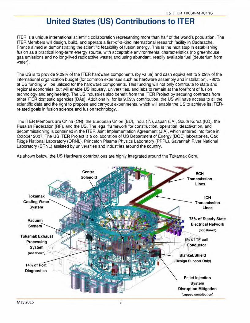
United States (US) Contributions to ITER
ITER is a unique international scientific collaboration representing more. than half of the. world's population .. The. ITER Members will. design, build, and operate a first-of-a-kind international. research facility in Cadarache, France aimed at demonstrating the scientific feasibility of fusion energy. This is the next step in establishing fusion as a practical long-term energy source, with acceptable environmental characteristics (no greenhouse gas emissions and no long-lived radioactive waste) and using abundant,. readily available fuel (deuterium from water).
The US is to provide 9.09% of the ITER hardware components (by value) and cash equivalent to 9.09% of the international organization budget (for common expenses such as. hardware assembly and installation). - 80% of US funding will be utilized for the hardware components. This funding will not only contribute to state and regional economies, but will enable US industry, universities, and labs to remain at the forefront of fusion technology and engineering. The. US industries. also benefit from the ITER. Project by securing contracts from other ITER domestic agencies (DAs). Additionally, for its 9.09% contribution, the US will have access to all the scientific data and the right to propose and carryout experiments, which will enable the US to achieve its ITERrelated goals in fusion science and fusion technology . .
The ITER Members are China (CN), the European Union (EU), India (IN), Japan (JA), South Korea (KO), the Russian Federation (RF), and the US. The legal framework for construction, operation, deactivation, and decommissioning is contained in the. ITER Joint Implementation Agreement (JIA), which entered into force in October 2007. The US ITER Project is a collaboration of US Department of Energy (DOE) laboratories, Oak Ridge National Laboratory (ORNL), Princeton Plasma Physics Laboratory (PPPL), Savannah River National Laboratory (SRNL) assisted by universities and industries. around the. country.
As shown below, the US Hardware contributions are highly integrated around the Tokamak Core.
Tokamak Cooling Water
System
Tokamak Exhaust i""":>Y"~'f
Processing / ..r
System , 1
(not shown)~~
14% of Port l Diagnostics ~
May 2015 3
ECH. Transmission
Lines
ICH Transmission
Lines
75% of Steady State. Electrical Network
-.... (not shown).
ra%'h(Tb coil L"
I _,.,01 pondu tor
A-' Blanket/Shield (Design Support Only)
Pellet Injection System
Disruption Mitigation (capped contribution)
US ITER 1OOOO-MR0110.
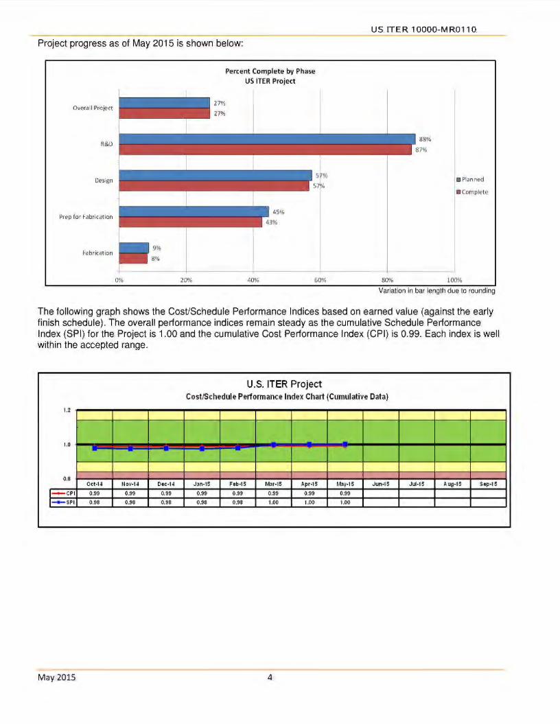
Project progress as of May 2015 is shown below:
Overall Project
R&D
Design
Prep for Fabrication
Fabrication 9%
8%
20%
Percent Co mplete by Phase
US ITER Project
40% 60%
• Planned
• complet e
80% 100%
Variation in bar length due to rounding
The following graph shows the Cost/Schedule Performance Indices based on earned value (against the early finish schedule). The overall performance indices remain steady as the cumulative Schedule Performance Index (SPI) for the Project is 1.00 and the cumulative Cost Performance Index (CPI) is 0.99. Each index is well within the accepted range.
U.S. ITER Project Cost/Schedule Performance Index Chart (Cumulative Data)
'l.2
'1.0 - - --- - - - -
o.a Oct-14 NOV·14 Dec-14 J3n·15 Feb·15 M3r-15 Apr·15 M3y·15 Jun-15 Jlf·15 Aug-1 5 Sep-1 5
I- CPI 0.99 0.99 0.99 0.99 0.99 0.99 0.99 0.99
1- SPI 0.98 0.98 0.98 0.98 0.98 1.00 ·1.00 1.00
May2015. 4.

US ITER 10000-MR0110
The. Project's actual. costs. and commitments through May 2015. compared to. the. obligation plan are. provided in the following graph.
(b )(5)
May 2015 5
I

M ay 2015
US ITER 10000-MR0110
Completed Deliveries of US ITER Hardware - 9% of total planned deliveries (343)
Complet ed D En route
FVlS Deliveries
i':JAS, Portable. RGA Station: Oct-14 A
i:iSEN, Earthing Resistors (Lot 1): Oct-14.A
SSEN, HV Substation. Transformers (Lot 2): Jan-15 A
S5EN, HV Control and Protection (Lot 2): Apr-15 A
ITF Conductor,. Conductor 1of9: May-15 A
$SEN, HV Substation Transformers (Lot 1): May-15 A
$SEN, HV Substation Transformers. (Lot 3): May-15 A
i:iSEN, HV Substation Transformers. (Lot 4 ): May-15. A
VAS, UHV Pumping Cart (Vacuum Test Equip 14 of 16) : Jun-15 (pending VAT resolut ion)
TCWS,. Drain Tanks. 1st Shipment: Jun-15.
SSEN,. 22kV Switchgear (Lot 1): Jun-15.
SSEN, 22kV Sw itchgear (Lot 2): Jun-15
~SEN, 6.GkV Sw itchgear (Lot 1): Jul-15
TCWS, Delivery of t he five cooling w ater drain. tanks: Aug-15
TF Conductor,. Conductor 2. of 9 : . Aug-15.
TF Conductor, l OOm Act ive (Luvat a): . Sep-15
SSEN, 6.6kV Switchgear (Lot 2): Sep-15
Total FVlS Deliveries To-Date
47%
Remaining FYlS
Deliveries 53%
US was the 151 Member to deliver ITER Hardware to the site
6

US ITER 10000-MR0110
Key Activities This Month
Steady State Electrical Network f SSEN)
The. remaining three (of four). SSEN High Voltage (HV) transformers were delivered to. the. ITER. site .. Two. main bodies of SSEN HV transformers were installed at the ITER site. These represent the first installation of key components. coming from any Domestic Agency.
Central Solenoid (CS) Modules and Structures
Manufacturing readiness reviews and commissioning of the. workstations at General Atomics. (GA) for CS module fabrication continue.
Pre-fabrication activities. for the. CS structure. lower key block components. are underway at Petersen, Inc ..
Fabrication of first article tie plates. for the CS structure. is underway at Major Tool and Machining and Precision Custom Components.
Toroidal Field (TF) Conductor
Packaging of the second Oxford Superconductor Technology production conductor is underway and the jacket assembly for the third production conductor is complete.
Tokamak Cooling Water Systems (TCWS)
Fabrication of the remaining three drain tanks continues.
Project Management
The US ITER Project Change Request (PCR) System was reviewed by Fermilab staff and selected as a project control tool to meet their change control requirements. This represents. the second software project controls tool distributed by US ITER and successfully installed at Fermilab.
May 2015 7

US ITER 10000-MR0110
Milestone Status
Thirty-three milestones were selected and approved for incorporation into. the US ITER. FY15. Performance Plan. The Plan was. reviewed/concurred by the. Federal Project Director (FPO) and has been reviewed and approved by DOE-FES.
One level 1 milestone (last delivery of the SSEN HV transformers) and one level 3 milestone (Pellet Injector system preliminary design review meeting) were completed this month.Twelve of the remaining 21 milestones are forecast to complete on or ahead of schedule . .
Of the 6 DOE milestones (2 late, 4 forecast late), three are due. to the resolution of the. ITER water activation issue and all but one are forecast to complete by the end of the FY.
The following table provides an overview of the milestone status by Level..
Total
Completed 12
On Schedule 12
Forecasted Late 6
Late 3
TOTAL 33
May 2015 8
FYlS. Performance Plan
Ll L2
3 2
- 3
- 4
1 1
4 10
l1: DOE FES milestone L2: DOE FPD milestone
L3
7
9
2
1
19
LJ: ORNL Project Manager milestone

CONTENTS
WBS 1.1.1 Magnet Systems - Oak Ridge National Laboratory (ORNL)
Central Solenoid (CS) Modules,. Structure,. and Assembly Tooling Toroidal Field (TF) Coil Conductor
WBS 1.2.1 Tokamak Cooling Water Systems (TCWS)-: ORNL .
WBS 1.3.1 Vacuum Pumping & Fueling Systems - ORNL Roughing Pump (RP) Sets Vacuum Auxiliary Systems (VAS) Pellet Injection (Pl) Disruption Mitigation (DM)
US ITE R 10000-M R0 110
WBS 1.3.2 Tokamak Exhaust Processing (TEP) Savannah River. National. Laboratory (SRNL)
Page 10
Page 13
Page.15
Page 18
WBS. 1.4.1 Steady State Electrical Network (SSEN) Princeton Plasma Physics Laboratory (PPPL) Page 19
WBS 1.5.1.1 Ion Cyclotron Heating (ICH) Transmission Lines - ORNL . ...
WBS 1.5.2.1 Electron Cyclotron Heating (ECH) Transmission. Lines - ORNL .
WBS 1.5.3 Diagnostics - . PPPL
WBS 1.6 Project Support - ORNL Procurement Human Resources Quality Assurance
WBS 1. 7 International Organization Support (Secondee and Cash Contributions) - ORNL
Cash Payments Secondees/Employees Total Credit Earned
WBS 1.8 Supplemental Task Agreements (TA) with the 10
WBS 1.9 Instrumentation. and Controls (l&C)
Appendix A - US ITER. Project Schedule .
Appendix B. - Project Change Requests processed this month.
Appendix C - Level 3 (Project Manager) FY15 Milestones .
May 2015 9
Page21
Page.22.
Page23.
Page 24
Page 25
Page 27
Page28.
Page29
Page30.
Page 31.

US ITER 10000-MR0110.
WBS 1.1.1 Magnet Systems - Oak Ridge National Laboratory (ORNL)
Central Solenoid (CS) Modules and Structure - Required for ITER 1 st Plasma
The US is responsible for the CS magnet, including design, R&D, and fabrication of six CS modules (coils) and. a spare module using supplied cable-in-conduit superconducting. conductor (from JA), the. vertical precompression structure,. Assembly Tooling (AT), bus extensions, and cooling connections.
The CS serves as the. backbone of the ITER magnet system. The CS induces the. majority of the magnetic flux change. needed to initiate. the plasma, generate. the plasma current, and. maintain this. current during the. burn time.
General Atomics (GA) in San Diego, California, has been awarded a major contract to fabricate the modules of the CS.
Preparations for CS Modules , CS Structure and Assembly Tooling fabrication continue
WBS 1.1.1. t- CS Modules.
Testing has. been underway to. determine. it the. order of peening and. heat treatment affect the residual stress in the toe of. the. He inlet weld.. The second. phase of testing was completed this month. It was found that the compressive stress at the. surface of the welds remains after heat treatment. Measurement through the. depth was delayed. in order to test the samples at the High Flux Isotope Reactor (HFIR) at ORNL. HFIR requested that the sample welds be undisturbed for their tests to determine residual. stress at shallow depths.
The final helium piping drawings have been approved. by the 10 .. The 10 has approved. 58. of 72 planned. drawings. 1 O of the 14 remaining drawings are in the approval process. The last 4 drawings to be completed will. be. the. top-level assembly drawings.
Module fabrication at GA is proceeding:
• Station 3 - Joint and. Terminal. Prep. - Work continues on the first hexapancake
for the mock-up coil. - The splice end. has the jacket removed.
and chrome stripping has begun.
• Station 4 - Stack and. Join ... . - Additional commissioning activities were.
performed to increase confidence in preparing splice joints. These. activities have concluded and. the first MRR has been scheduled. for June. 11 . .
- 26 of 31 weld samples have passed radiographic examination and test coupons are being prepared for
May2015. 10
mechanical. testing at room temperature and at 4K.
- The remaining weld samples have. passed initial radiographic examination and are being. heat. treated .. All required weld qualification for mock-up processing has. been accomplished ..
• Station 5.-: Reaction. Heat Treatment. . - The commission ing coil. is being heat
treated in preparation for completing commissioning activities ..
- The first MRR is scheduled for June 9.
• Station 6 - Turn Insulation. - Commissioning activities are continuing
for Station 6. The MRR will. be later than planned (forecast in August) due. to. issues with JK2LB supply and weld qualification.
- Demonstration of the automated insulation wrapping head on the. long lead was successful.
- Strain gauges were installed on a conductor sample containing a T2 long lead ...
• Station 7-: Ground. Insulation. - Commissioning activities are. continuing
for Station 7. - . The. second helium penetration sample
was successfully tested at 1 SOkV for approximately. 30. seconds before an electrical breakdown occurred.

USITER 10000-MR0110
CS Modules
Begin winding the. first central solenoid module 1 14-Apr-15 23-Mar-15 A
Conduct Turn Insulation MRR 2 02-Jul-15 24-Aug-15
~ Completed • =On-Schedule _fl Forecast to Miss PP Date • =Missed PP Date ]
WBS 1.1.1.2 - CS Structures
Pre-fabrication activities continued at Petersen, Inc. for manufacturing the lower key block components.
Two fabricators, Major Tool and Machine and Precision Custom Components, are. now fabricating
CS Structures
=Completed =On-Schedule
WBS 1.1.1.4 - CS Assembly Tooling (AT)
The Lifting Fixture follow-up FDR is now scheduled for June 15-16,. 2015. - The. design analysis and calculations. (DAG) was
completed and is under review.
May2015 11
first article. outer tie. plates. Award of the. fabrication contract for upper components is expected in June.
- All. drawings (42) have been submitted. - All. models and drawings have. been drafted and
replicated for 10 review,. which has. begun.
US ITER 10000-MR0110
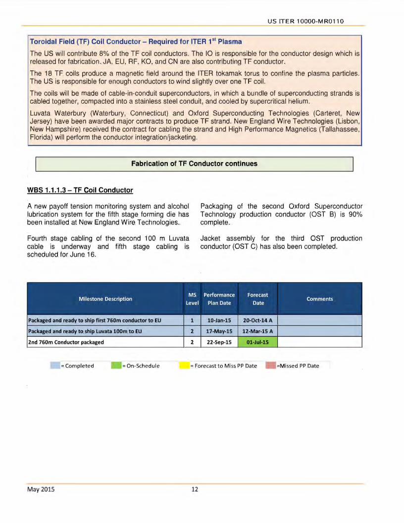
Toroidal. Field (TF) Coil. Conductor- Required for ITER 151 Plasma
The US will contribute 8% of the TF coil conductors. The 10 is responsible for the conductor design which is released for. fabrication. JA, EU, RF, KO, and CN are. also contributing TF conductor ..
The 18. TF coils produce a magnetic field around the ITER tokamak torus to confine the plasma particles. The US is responsible for enough conductors to wind slightly over one TF coil.
The coils will be made of cable-in-conduit superconductors, in which a bundle of superconducting strands is cabled together, compacted into a stainless steel conduit, and cooled by supercritical helium.
Luvata Waterbury (Waterbury, Connecticut) and Oxford Superconducting Technologies (Carteret, New Jersey) have been awarded major contracts to produce TF strand. New England Wire Technologies (Lisbon, New Hampshire) received the contract for cabling the strand and High Performance Magnetics (Tallahassee, Florida) will perform the conductor integration/jacketing.
Fabrication of TF Conductor continues.
WBS 1.1.1 .3 - TF Coil Conductor
A new payoff tension monitoring system and alcohol lubrication system for the fifth stage forming die has been installed at New England Wire. Technologies ..
Fourth stage cabling of the second 1 00 m Luvata cable is underway and fifth stage cabling is scheduled for June. 16.
Packaged and ready to ship first 760m conductor to EU
Packaged and ready to. ship Luvata lOOm. to EU
2nd 760m Conductor packaged
= Completed = On-Schedule
May 2015
1
2
2
Packaging of the second Oxford Superconductor Technology production conductor (OST B) is 90% complete.
Jacket assembly for the third OST production conductor (OST C) has also. been completed.
10-Jan-15 20-0ct-14 A
17-May-15 12-Mar-15 A
22-Sep-15 01-Jul-15
= Forecast to Miss. PP Date =Missed PP Date
12

US ITER 10000-MR0110
WBS 1.2.1 Tokamak Cooling Water Systems (TCWS) - ORNL
TCWS - Portions. of. the system required for ITER 1 st Plasma
The US is responsible for the design, engineering, and procurement of TCWS.
ITER's fusion power will reach 500 MW during the deuterium-tritium inductive plasma operation with an energy input of only 50 MW,. yielding an energy multiplication factor of 10. Heat will be transferred. by the. TCWS from client systems to the environment through the secondary cooling system. TCWS is designed to cool client systems, such as the first wall/blanket, vacuum vessel, divertor, and neutral beam injector (NBI). Additional operations include baking of in-vessel components, chemical control of water provided to client systems, draining and drying for maintenance, and leak detection/localization.
The TCWS interfaces with the majority of ITER systems, including the secondary cooling system, which rejects this heat to the. environment. Plasma operations are inherently safe because a functioning cooling water system is not required to ensure safe shutdown.
System Design and Fabrication of the remaining. three (of five) Drain Tanks continue.
Design
Integrated Blanket Edge Localized Mode Divertor (IBED) Primary Heat Transfer System (PHTS) piping and shielding 3D layout continues,. as. authorized under PCR-662, with focus on the relocation of IBED PHTS equipment previously on Level L4 to Level L3 and the routing of piping in the space between the cryostat and the bioshield . .
The DOE Performance Plan milestone, "Develop a resource-loaded schedule for completion of the final design, incorporating the. design solution for the
Fabrication of Drain Tanks
Normal Drain Tanks 2A and 28 were. delivered. to the ITER site. Issues associated with the. resolution of rust spots found during receipt inspection, as well. as accelerometer readings. during transport, are being resolved.
Fabrication of the remaining three tanks is. nearing completion with preparation for transportation expected by late June 2015. The. status as of late. May is:
- Neutral Beam Injection Tank - Nozzle N7 found out of tolerance and is being documented and approved with QA documentation (i.e., NonConformance Report) . . Hydrostatic leak testing is scheduled for early June.
May 2015 13
gamma radiation issue", is forecast to be completed on June 1, 2015 by establishing a Design Plan to close PCR-662.This will ensure that the. 10 covers the cost of performing these activities, and linking the Design Plan schedule. activities. to. 10 -TCWS Arrangement activities to establish the delay in the design . .
The 10 initiated an evaluation of the fiber optical sensors for resolving issues associated with exposure to radiation and magnetic fields.
- Safety Drain Tank 1 A - Shrink Wrapping complete with final inspections scheduled.
Safety Drain Tank 2A - External Inspection in progress with additional grinding to occur, if needed,. followed by completion of ANB visual inspections of external. surfaces.
Fabrication of TCWS Piping
The award of the ITER organization's framework contract for TCWS pipings and fittings remains on hold until resolution of the water activation issue.

Delivery of the five cooling water drain tanks. to. port in France complete
Develop a resource-loaded schedule. for completion of the Final Design,
incorporating the design solution for the gamma radiation. issue.
10 Awards Framework contract for TCWS Pipings & Fittings
US ITE R 10000-MR0110
1
2
2 31-Jul-15
= Completed = On-Schedule = Forecast to Miss PP Date • =Missed PP Date
May 2015 14

US ITER 10000-MR0110
WBS 1.3.1 Vacuum Pumping & Fueling Systems - ORNL
Roughing. Pump Sets - A portion of. the components required for ITER 1 st Plasma
The US will contribute 100% of the ITER roughing pumps.
The ITER tokamak, cryostat, and auxiliary vacuum chambers must be evacuated prior to and during operations .. The roughing. pump system exhausts the. torus and NBI cryopumps,. service. vacuum, and cryostat. This system will utilize a matrix of pump trains with various technologies to match specific vacuum system requirements, including tritium-compatible backing pumps for torus and neutral beam cryopumps.
Support to the 10 for Conceptual Design continues
WBS 1.3.1. t - Roughing Pump Sets.
The test data from the initial round of cryogenic viscous compressor (CVC) performance testing in the ORNL Spallation Neutron Source (SNS) Cryogenic Test Facility (CTF) is. being analyzed to determine what equipment adjustments will be required to achieve the desired performance and when such subsequent testing can be. performed.
The final test report on the performance testing of the tritium compatible prototype roots and screw vacuum pump train was submitted to the 10.
Discussions were initiated with the 10 on the revision of the. associated Task Agreement for the. inclusion of the test stand as a deliverable. The repackaging of the. pumps for shipment to. the 10 was. initiated.
The initial results of the performance testing of an alternative tritium compatible roots. pump stack being conducted at Oerlikon/Leybold were evaluated.
Vacuum Auxiliary System (VAS) - A portion of the. system required for ITER 1 st. Plasma
The US will design and procure the ITER vacuum auxiliary system.
The vacuum auxiliary system consists of valves, pipe manifolds, auxiliary pumps, sensors, and controls. The torus and NBI vacuum manifolds of this system need to be tritium compatible ..
The Vacuum Auxiliary System Procurement Arrangement 3.1.P4.US.01 (designated as VAS-01 ) scope includes the design and procurement of those components associated with the vacuum piping which. serve as the manifolds providing vacuum service throughout the Tokamak Building.
The Vacuum Auxiliary System Procurement Arrangement 3.1 .P4.US.02. (designated as. VAS-02) scope. includes the design and procurement of those vacuum components which connect the vacuum manifolds provided in VAS-01 to the. clients (ITER technical. systems) requiring vacuum service. throughout the Tokamak Building.
Design continues. and preparations for fabrication have begun
WBS 1.3.1.2 - Vacuum Auxiliary Systems (VASl
Design
VAS-01 Scope:
Final design and analysis of the VAS-Ol piping systems on levels. L 1 and L2 continues to progress while the design of the piping systems on levels L3,
May 2015 15
L4 and. LS remain on hold. pending the finalization of changes associated with PCR-662. (ITER water activation issue).

VAS-02 Scope:
Continued development of the VAS-02 Cryogenic Guard Vacuum System (CGVS), Service Vacuum
Fabrication
VAS-01 Scope:
Procurement related documentation associated with the supply of the piping vacuum flanges, custom pipe
VAS
US ITER 1OOOO-MR0110.
System (SVS) and Type 2. Diagnostic Vacuum Pumping Systems (T2DVPS) final design details.
supports and Clamshell. leak test fixtures was initiated.
MS Performance Forecast Milestone Description Level Plan Date Date Comments
--- -=Completed =On· Schedule =Forecast to Miss PP Date • =Missed PP Date
Pellet Injector {Pl) System - A portion of the system required for building integration prior to ITER 151
Plasma
The US will design and procure the Pl system.
Pl provides efficient core and edge fueling and will deliver hydrogen, deuterium, or. a deuterium/tritium mixture as required by plasma operations. Delivering fuel pellets to the plasma edge mitigates ELM (edge localized mode) instabilities.
R&D and Preliminary Design Activities. continue
WBS 1.3.1.3 - Pellet Injection
A load specification for the flight tubes preliminary design review (PDR) was completed and transmitted to the 10 . All changes in the flight tube design from the. April visit were. incorporated in preparation for the. PDR in June.
The. pellet injection Systems Level. PDR with. the 10 was conducted on May 13•h.
Difficulty with leaks on the twin screw extruder test unit has delayed the completion of fabrication. The
M ay 2015. 16
problematic leaks are at the brazed joints in the extruder body. The issues are being addressed with the supplier and completion is expected in June with testing resuming shortly after.

US ITE R 10000-MR0110
Disruption Mitigation - System not required for ITER 151 Plasma
The US will contribute up to a capped value. for the Disruption Mitigation System (OMS). The system has two functions, 1) limiting the. impacts of plasma current disruptions to. the tokamak vacuum vessel, first wall blankets and other in-vessel components and, 2) suppressing the formation and deleterious effects of highenergy runaway electrons. Out of port plug installation of shattered pellet injection (SPI) units at four port locations that are designed to also function as massive. gas injection (MGI) units is the current plan for the OMS. In addition, an option for an MGI unit within a port plug. is included. This unit is to be designed to function during non-nuclear operations only. to. provide operational experience of. a fast acting MGI unit close. to. the plasma.
Preliminary Design Activities continue
WBS 1.3.1.4 - Disruption Mitigation
A service panel designed to operate the test massive gas injection (MGI) valve over many repetitions was designed and is under fabrication. The. panel will be used to monitor the gas pressures and to remotely operate. the valve for extended durability testing. Fabrication is expected to complete in June, with testing to resume. afterwards.
Several options for testing an MGI valve in a high magnetic field are being explored. To. date,. two possible locations, the University of Minnesota and Los Alamos National Laboratory, are identified as possible facilities with the capabilities of testing the valve. in ITER-like magnetic fields.
Design is underway of a flyer-plate driven shattered pellet injector (SPI) valve for ITER. The new design incorporates features to improve manufacturability, maintainability, and performance. The flyer plate has been relocated from typical valves to the discharge end of the valve,. simplifying construction and
May 2015 17
improving performance, and the coil. has been moved outside of the pressure boundaries.
CAD rendering of the SPI flyer plate driven valve. The coils (orange) have been moved outside of the pressure boundary.
US ITER 10000-MR0110
WBS 1.3.2 Tokamak Exhaust Processing (TEP) - Savannah River National Laboratory (SRNL)
TEP - System not required for ITER 1 st Plasma
The. US is responsible for the. Final Design (FD), fabrication, assembly, testing, and shipment of the TEP system.
ITER will require the processing of an unprecedented rate of hydrogen isotopes. To facilitate environmental responsibility and economic application of fusion technology, the reuse of hydrogen isotopes is vital. The TEP system must separate the exhaust gases into a stream containing only hydrogen isotopes and a stream containing only non-hydrogen gases. The implementation of the TEP system will provide a technically mature, robust, and cost-effective separation solution.
The TEP system consists of. a series of filters, catalysts,. and permeators (PM). to separate the hydrogen isotopes, which are then sent to an isotope separation system (furnished by the EU) to deliver deuterium and tritium for continuous reinjection into the reactor.
Support for Preliminary Design Activities continues
Preliminary design is the responsibility of the 10. A Task Agreement (TA) to the US delineates the part of the. design to be. performed by the US ITER TEP team. The. US TEP design team has completed approximately 50% of Subtask-2 TEP Process. Studies. All. studies have. been started and five of the. studies are. drafted. A set of reference documents,
May 2015 18
initial assumptions and a request for additional reference information was developed and sent to 10 . Results of the studies will. remain as 'draft' until the input information receives 10 concurrence . . Receipt of the final input from the 10 is now scheduled for June ...

US ITER 10000-MR0110
WBS 1.4.1 Steady State Electrical Network (SSEN) - Princeton Plasma Physics Laboratory (PPPL)
SSEN - Hardware required for ITER 1 st Plasma
The US contributes 75% of the equipment required for the SSEN, excluding cables and emergency power. The. EU contributes the remaining equipment and is also responsible for the. design and installation of. the. system as well as all cabling and all emergency (diesel generator) power systems.
The SSEN is an alternating current (AC) power substation and distribution system that supplies electrical power to all ITER conventional systems and facilities. A separate system delivers power to the pulsed systems, including the magnet and heating power supplies.
The SSEN is rated at 120 MW and is. similar to the auxiliary power distribution system in a nuclear fission power plant, except that it is about twice the size. The equipment to be. contributed by the US is typical of a large AC power distribution system, consisting of transformers and switchgear at the. high-voltage (400 kV) and medium-voltage (22 kV) levels.
Hardware. Procurements. and Shipments. continue
Twelve of 16 contracts have been signed and/or executed.. Procurement of another contract is underway and the remaining 3 are on hold due to funding constraints .. A total of 18 of 31 shipments have been completed. Status of the 16 SSEN procurements. is. as follows:
• The HV Substation Transformers j{b)(5) I l(b)(5) lhave all been successfully delivered to the ITER site. Processing of Delivery Reports is underway, after which ownership of site support and warranty can be. transferred to ITER. and credit can be requested.
• The HV Circuit Breakers, HV Switches, HV Current Transformers, HV Potential Transformers, HV Surge Arresters, HV Substation Hardware,. Earthing Resistors, and the HV Control & Protection have all been delivered to the ITER site .. The final Delivery Reports and transfer ownership of site support and warranty are being processed for these items, after which ITER. credit will be requested.
• The 22kV Switchgear l<b)(5) l<b )(5)
May 2015 19
l<b)(5) I Release for Shipping (RFS) documentation package review is. underway, and shipping is planned to take place in June.
• The 6.6kV Switchgead (b)(5) I l(b)(5) I was started .. Lot l was completed and successfully. factory acceptance tested.
• The Power Transformers l<b)(5) l<b)(5) Design Review was successfully conducted in April and chit resolution is underway. The next step will. be to. issue. a Release. for Manufacturing.
• US ITER authorized the procurement of the Reactive Power Compensators in FY15 so a Subcontract Proposal Evaluation Board (SPEB) was formed and preparations started on the Request for Proposal (RFP) package.
• DC Distribution, UPS, and LV Distribution & Sub-distribution Panels procurement activities are on hold due to funding constraints ..

US ITE R 10000-M R0 110
SSEN
IPL> Dellvery of HV Substation Transformers (Lot 4) by US-DA to ITER Sit e 1 27-May-15 21-M ay-15 A
Packaged and ready to ship - 6.6kV Switchgear (Lot 1) 2 28-Jun-15 07-Jul-15
Packaged and ready to ship - 22kV Swit chgear (Lot 2) 2 16-Jul-15 08-Jun-15
= Co!!!Jlleted • =On-Schedule =Forecast to Miss PP Date • =Missed PP Date J
May 2015 20

US ITER 10000-MR0110
WBS 1.5.1.1 Ion Cyclotron Heating (ICH) Transmission Lines - ORNL
IC Transmission Lines- A portion of the system is required for building integration prior to ITER 1st Plasma
The US is responsible for the IC transmission lines, including R&D, design, fabrication, and interfaces. The 10 is responsible for installing the IC transmission lines.
The IC system heats the ions in the plasma with a high-intensity beam of electromagnetic (EM) radiation. Generators produce high-power radio frequency waves that are carried along multiple transmission lines to antennas located in the vacuum vessel , sending the waves into the plasma. The US IC transmission lines will provide efficient power transfer from 40-55 MHz radio frequency sources to the plasma heating antennas. The system will include coaxial transmission lines and a matching/tuning system to minimize power transfer losses. The pressurized lines can transmit up to 6 MW per line. In total, approximately 1.5 km of line connects 8 sources to 16 antenna feeds, with 14 types of transmission line and matching system components. The main interfaces include sources, launchers, buildings, port cells, and water cooling. The short coaxial line also provides secondary tritium confinement.
Preliminary Design Activities continue
Design kickoff meetings were completed with the vendor teams that are in the first phase of developing designs of 3-meter-long stub tuners. The. ICH tuning/matching system requires the use of up to ninety-six of these mechanically driven internal sliding shorts.
May 2015 21
Issued Request for Proposal (RFP) for the design and fabrication of a rotary joint test article. The rotary joint will compensate. for thermal. expansion ITER vacuum vessel. and length expansion of the ICH transmission lines when operating at high power.
US ITER 10000-MR0110
WBS 1.5.2.1 Electron Cyclotron Heating {ECH) Transmission Lines - ORNL
EC Transmission Lines - A portion of the system is required for ITER 151 Plasma
The US is responsible for the EC transmission lines, including R&D, design, fabrication, and interfaces. The 10 is responsible for installing the EC transmission lines.
The EC system heats the electrons in the plasma with a high-intensity beam of electromagnetic radiation. This system is also used to deposit heat in very specific places in the. plasma. Power will be provided by powerful , high-frequency gyrotrons. The US transmission line design will provide efficient power transfer from 170 GHz gyrotron sources to plasma heating power launchers (20 MW).
The transmission lines feature multiple lines of evacuated aluminum waveguides with internal corrugations that can transmit 1.5 MW per line for 3000 seconds, while minimizing power transfer losses to ~ 10%. Approximately 4 km of transmission line will be part of this system, connecting 24 sources to. 56 feeds with 1 O types of waveguide components. The main interfaces include sources, launchers, buildings, port cells, water cooling, and auxiliary vacuum. The waveguide also provides secondary tritium confinement.
Final Design Activities continue
The statement of work and technical specifications for the ECH transmission line gyrotron commissioning power loads (dummy loads) was completed. Dummy loads are devices designed to absorb the generated power from the gyrotrons during installation, commissioning, and conditioning. Each gyrotron has a switch that can direct power to either the ITER tokamak or the dedicated long pulse dummy load.
Bids. from five vendors were evaluated for a Basic Ordering Agreement (BOA) for "Process Development and Manufacture of 4.2m Waveguide
May2015 22
and Associated Components". The long straight sections of the ECH transmission line need to be manufactured with high precision in both straightness and section-to-section alignment in order to minimize power losses. Bids were also evaluated for the initial BOA task .. The initial task is for BOA vendors. to provide their evaluation of existing and alternative manufacturing process options. Subsequent tasks. include qualification of the selected manufacturing process and the. manufacture of approximately. 1800, 4.2m long, ECH waveguide sections.
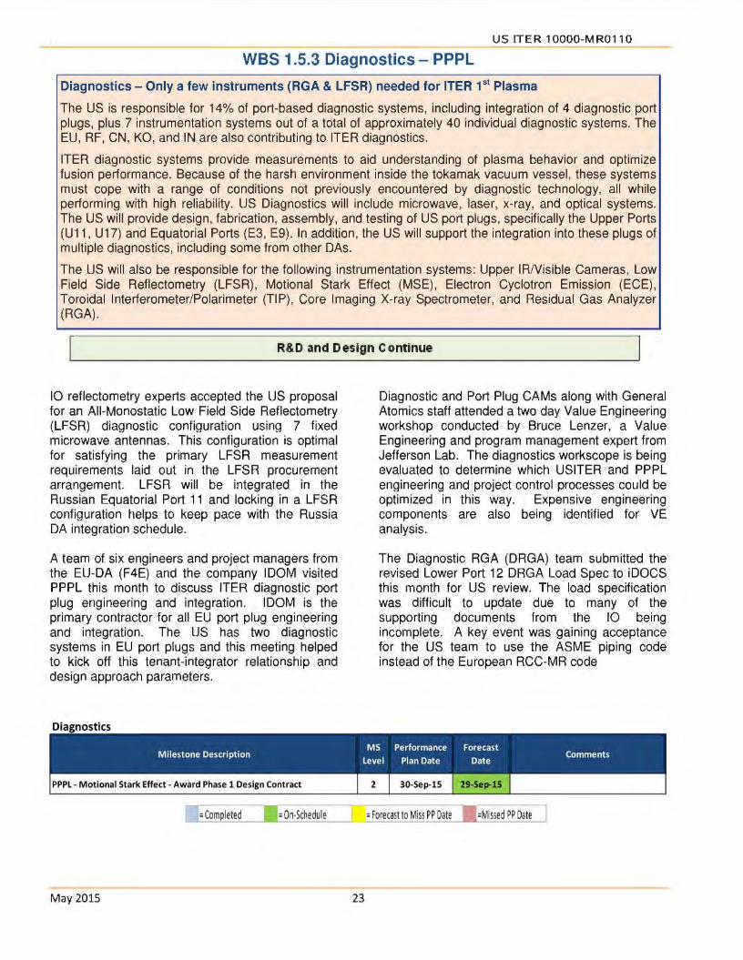
US ITER 10000-MR0110
WBS 1.5.3 Diagnostics - PPPL
Diagnostics - Only a few instruments (RGA & LFSR) needed for ITER 1 st Plasma
The US is responsible for 14% of port-based diagnostic systems, including integration of 4 diagnostic port plugs, plus 7 instrumentation systems out of a total of approximately 40 individual diagnostic systems. The EU, RF, CN, KO, and IN are also contributing to ITER diagnostics.
ITER diagnostic systems provide measurements to aid understanding of plasma behavior and optimize fusion performance. Because of the harsh environment inside the tokamak vacuum vessel, these systems must cope with a range of conditions not previously encountered by diagnostic technology, all while performing with high reliability. US Diagnostics will include microwave, laser, x-ray, and optical systems. The US will provide design, fabrication, assembly, and testing of US port plugs, specifically the Upper Ports (U11, U 17) and Equatorial Ports (E3, E9). In addition, the US will support the integration into these plugs of multiple diagnostics, including some from other DAs.
The US will also be responsible for the following instrumentation systems: Upper IA/Visible Cameras, Low Field Side Reflectometry (LFSR), Motional Stark Effect (MSE), Electron Cyclotron Emission (ECE), Toroidal Interferometer/Polarimeter (TIP), Core Imaging X-ray Spectrometer, and Residual Gas Analyzer (RGA).
R&D and Design Continue
10 reflectometry experts accepted the US proposal for an All-Monostatic Low Field Side Reflectometry (LFSR) diagnostic configuration using 7 fixed microwave antennas. This configuration is optimal for satisfying the primary LFSR measurement requirements laid out in the LFSR procurement arrangement. LFSR will be integrated in the Russian Equatorial Port 11 and locking in a LFSR configuration helps to keep pace with the Russia DA integration schedule.
A team of. six engineers and project managers from the EU-DA (F4E) and the company IDOM visited PPPL this month to discuss ITER diagnostic port plug engineering and integration. IDOM is the primary contractor for all EU port plug engineering and integration. The US has two diagnostic systems. in EU port plugs and this. meeting helped to kick off this tenant-integrator relationship and design approach parameters.
Diagnostics
D =Completed l =On·Schedule
May 2015 23
Diagnostic and Port Plug CAMs along with General Atomics staff attended a two day Value Engineering workshop conducted by Bruce Lenzer, a Value Engineering and program management expert from Jefferson Lab. The diagnostics workscope is being evaluated to determine which USITER and PPPL engineering and project control processes could be optimized in this way. Expensive engineering components are also being identified for VE analysis.
The Diagnostic RGA (DRGA) team submitted the revised Lower Port 12 DRGA Load Spec to iDOCS this month for US review. The load specification was difficult to update due to many of the supporting documents from the 10 being incomplete. A key event was gaining acceptance for the US team to use the ASME piping code. instead of the European RCC-MR code

US ITER 10000-MR0110
WBS 1.6 Project Support - ORNL
Procurement
Key procurement actions for May included:
• A Modification for Task Order 6 Fabrication Management Funding (1.6.3) was issued to AREVA ($78,614)
Human Resources
One posting closed for the ITER Organization in May and two US candidates were nominated for review. Five US candidates were selected to interview for the Quality Assurance & Assessment Division Head and Communication Head positions. Also, two new
• A Modification for Transport of TF 1 OOm Luvata Conductor (1 .1.1.3.9) was issued to Transproject ($10,082)
positions were posted for a Structural Analysis Civil Engineer and a Construction Coordinator for which the Human Resources team continues to review applicants.
Category of European India Japan China Korea Russian United Total staff Union Federation States
DES 228 13 20 26 25 20 16 348
SEC 11. 11.
Total 239 13 20 26 25 20 16 359
Post Doc 3 1. 1. 5
VRs 1. 1. 2
66.6%. 3.6%. 5.6%. 7.2%. 7.0%. 5.6%. 4.5%.
Quality Assurance (QA) .
Inspections by Bureau Veritas (under contract to 10) of TCWS drain tanks fabrication activities at Joseph Oat Corporation continued. One report received for May inspections was statused as SATISFACTORY.
PPPL quality inspector completed eight visits to Joseph Oat Corporation in May to assess and report on fabrication progress for the NBI and Safety drain tanks.
May 2015 24
DES: directly employed staff by. the 10; SEC: Secondees to the 10; VRs: Visiting Researchers at the. 10
Follow-up assessments were performed at High Performance Magnetics (HPM) and National High Magnetic Field Laboratory (NHMFL) during May:
• HPM follow up surveillance and witnessing of 770m cable insertion/compaction.
• NHMFL surveillance, sampl heat treating capabilities.

US ITER 10000-MR0110
WBS 1.7 International Organization Support
(Secondees and Cash Contributions) - ORNL
Per the JIA,. the US is obligated to contribute 9.09% of the value estimate. of. the construction of ITER. The contributions are measured in ITER kilo Units of Account (klUA), which has been used by ITER for. many years; 1 klUA equals $1 M US dollars (January 1989). The US commitment,. 424.618 klUA, includes hardware fabricated/procured by. the US, cash for installation and commissioning, staff. (secondees or. cash for direct employees), and cash for R&D. directed by the 10.
The US can also receive. credit (klUAs) for performing additional. work through approved Task Agreements (TAs). The US will cover its share of the cash contributions through cash payments in current year Euros. upon request by the. 10. Euros are purchased with current year dollars using the current exchange. rate when the payment is due. To establish the klUA value. of. annual cash contributions, the. Euros are de-escalated to Euros (January 1989) using proven inflation rates, and then converted to millions of. dollars. (January 1989) to yield klUA ..
Note: the. tables below reflect a new decision not to. grant credit for contributions ta the. 10 prior. to CY 2007 .. The. Cash Payments Table. contains the. 2006 cash contribution but the. credit does not contain this. 2006 value ..
Cash Payments
Calendar Budgeted € Paid € Paid$
Remaining Year Obli~ation €
2006 409,000 € 409,000 € $528,918.80 0
2007 3,985,000 € 3,985,026.06 € $5,463,23 1. 76 0
2009 15,689,630.70 € 15,689,604.64 € $21 ,102,518.24 0
2010 9,567,409 € 9,567,409 € $13,552,234.85 0
2010 1,577,433 € 1,577,433 € $2,018,010.04 0
Sunnlemental 2011 Advance
9,132,173 € 9,132,173 € $11 ,650,826.31 0 Payment
2012 9,450,359 € 9,450,359 € $12,133,315.92 0
2013 17,672,925 € 17 ,672,925 € $23,975,973.67 0
2014 14,885,339 € 14,885,339 € $20,280,343.91 0
2015 13,741,328 € 13,741,328 € $14,827,218.12 0
Cumulative 96,110,596.70€ 96,110,596. 70€ $125,532,591.62 0
Estimated Credit Earned to date: 59.284 kIUA
Average Exchange Rate realized for cash paid = 1.306
May 2015. 25

US ITER 10000-MR0110
Secondees/Employees
U.S. Secondees. Credit Earned: 1.531 kIU As
CmTent Number of Secondees: 0. U.S. Direct Hires Current Number of U.S. Direct Hires: 37
l New Hire sta1t ing in August 2015.
Total Credit Earned (-20% of total. planned)
Total Planned Actual Credit Change In Remaining Allocation Credit klUA Received klUA Actual Credit klUA
1.531 1.531 207.520 11.730 195.790
15.193 12.685 2.508
202.986 59.284 143.702
427.230 85.230 342.000
2007 2008 2009 2010 2011 2012 2013 Cash 2.711 0 10.138 13.063 0 5.835 10.645 Secondees .629 .274 .277 .246 .105 0 0 TAs 0 .300 .048 2.284 4.611 2.497 1.939 PAs 0 0 0 2.500 0 5.850 0 Total 3.3-10 .574 10.463 18.093 4.716 14.182 12.486
2014 2015 Total Cash 8.842 8.050 59.284 Secondees 0 0 1.531 TAs 1.006 0 12.685 PAs 3.380 0 11. 730 Total 13.228 8. 050 85.230
M ay 2015. 26

US ITER 10000-MR0110
WBS 1.8 Supplemental Task Agreements (TA) with the 10
Task Agreements currently in-progress
Credit Credit Received.
Amount to Date Expected TA# Description Aaencv US Contact (klUA) (klUA) TA Start Finish
TA-FC·IPT-US·RP-01 Validation of Mechanical Roughing Concepts US-IPO M Hechler, Larry
0.435 01/0212011 0711512015 Baylor
C.74 TD 21 FU Neutronics Analys is Support for ITER ORNL I U. of Wisc. B. Nelson. /
0.318 09/0112014 0913012015 Ml ha med. Saw an
TA·FC·IPT·US·RP-02 ITER Roughing System. Cryogenic Viscous Flow
US·IPO M Hechler, Larry
0.267 01/0212011 1112412015 Compressor Development Baylor
C.55 TD 36 FU Generic Diagnostic First Wall Preliminary and Final Design PPPL Wayne Steffey,
1.237 0.322 09/0112012 03131 /2016 Doua Laesser
C18TD35FU Development of ITER class. Pellet Injector US·IPO D. Rasmussen 0 10/0112008 0712812016
TA-FC·IPT·US-13·01 Preliminary Design Tasks associated.with. PBS 32.EP. Plant
SRNL Bernice Rogers 0.571 10/1712013 06/3012017 Svstem
TA-FC-IPT-US-RP-03 Validation ol Piston. Pump for. ITER Roughing. System US-IPO Da\1:! Rasmussen,
0.002 10/1712012 11130/2017 Larry Bayior
Total klUA 2.830 .. 0.322 Approx.$ $...6 248 000 $ 711 000
M ay 2015. 27

US ITER 10000-MR0110
WBS 1.9 Instrumentation and Controls (l&C)
Centralized Instrumentation and Controls Support. Required for ITER 1 st Plasma
The. US is responsible to provide l&G for all Procurement Arrangements (except Magnets and SSEN). Work scope includes: conceptual, preliminary, and final l&C design; l&C software design; l&G hardware. and software. procurement;. l&G equipment fabrication ; and l&C qualification and testing. The. WBS 1.9. work scope definition includes the majority of US DA l&G work scope, but the details will be defined on a WBS-byWBS basis. (e.g. Some. major equipment procurements will. include. l&C content; some. engineering services. contracts. such. as for Diagnostics will include l&G content; etc. so. this work scope will. remain in the other WBS areas). Benefits of a centralized l&C support include: sharing of specialized engineering resources; the promotion of standard designs, standard software components, and standard equipment; and the provision of common! -re uired services includin technical and ualification su ort.
Assembling l&C team and starting Conceptual and Preliminary Designs
WBS 1.9. Instrumentation and Control - ORNL
The. l&C WBS. Team Leader visited the. 10 for first time and met with the Control. System Division head and his. staff . . Meetings were conducted on radiation hardness assurance policy developments and status of neutronics. simulation,. as well as ICH. machine. protection.
M ay 2015. 28
A summer intern has. started setting up a prototype l&G database.
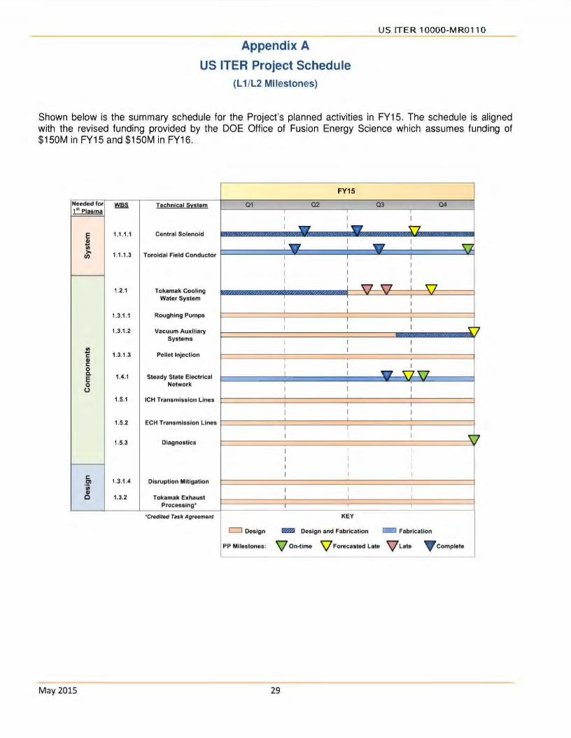
Appendix A
US ITER Project Schedule {L 1/L2 Milestones)
USITER 10000-MR0110
Shown below is. the. summary schedule. for the. Project's planned activities in FY15. The. schedule is. aligned with the revised funding provided by the DOE Office of Fusion Energy Science which. assumes funding of $150M in FY15 and $150M in FY16.
FY15 -Needed for ~ Technical Sl!stem 01 02 03 04 1'
1 l!li!~!lli! I
I I I I - I ""7
E 1.1.1.1 Central Solenoid
~ I V'7 I T"'7
I 5J-Cl) I I
:.. - -VI 1.1.1.3 Toroidal Field Conductor I I I
I I I I I I I I I
1.2.1 Tokamak Cooling I I '5:7_ I v v v
Water System I I
I I I I I I
1.3.1.1 Roughing Pumps I I I -
1.3.1.2 Vacuum Auxiliary I I I
' Systems I I I
.C!! I I I c 1.3.1.3 Pellet Injection QI .,.-c I I I 0 c. 1.4.1 I I ~ 5:JSJ-E Steady State Electrical -0 Network
I I 0 I 1.5.1 ICH Transmission Lines
I I I
I I I
I I I
1.5.2 ECH Transmission Lines I ' I
I I I
I I I ' 1.5.3 Diagnostics
I I I I I I
I I c I I I en 1.3.1.4 Disruption Mitigation 'jjj
I I I GI c 1.3.2 Tokamak Exhaust I I I
Processing• I I I
'Credited Task Agreement KEY
c::J Design Fm.I Design and Fabrication c=I Fabrication
PP Miiestones: \lon-tlmo \l Forecastod Lato \lLato V comploto
May2015. 29

USITER 10000-MR0110.
Appendix B
Project Change Requests processed this month
There were thirteen Project Change Requests (PCRs) processed in May. All PCRs. were. reviewed against the contingency guidance to determine the applicable usage of Management Reserve and DOE-held contingency.
All PCRs were Level 3 (Project) .
l111>act ($M)
Month Description Management DOE
PCR# WBS Reserve . Contingency
May IC-2015-3 ICH Design. Review. Restructure 1.5.1.1 .. .... .. .. .. (0.100)
May DA-2015-10 RGA - l&C Fabrication Missing Effort Fix 1.5.3.6 . (0.670)
May VF-2015-5 Advance. Dust. Fi l ter Procurement 1.3.1.2 ............ 0.008
May RP-2015-4 Advance CVC andCSS Procurements 1.3.1.1 .. 0.088
May ST-2015-5 Incorporate schedules.and.contract values from awarded
1.1.1.2 ... .. (0.987) contracts for Tie Plates
May ST-2015-6 Incorporate latest. vendor. schedule. for the Lower. Keyblock
1.1.1.2 -Assemblv contract
May CS-2015-18 Full. BCWS re plan for all of General Atomics 1.1.1.1 . . . . . . . . .
May VF-2015-6 Hood.Clamshell Tools 1.3.1.2 . (0.113)
May CS-2015-19 GA's cost fee and pending changes real ignment 1.1.1.1 .... ··· ·· ... ..........
May CW-2015-10 Transfer.of Hours.to 1.5.1&.Correction.ofHours 1.2.1 .................. -
May DA-2015-12 Diagnostics-. May. 2015 -. WAV Subcontract,. TIP.Subcontract, EP03,.
1.5.3 (11.434) D-Site Ooerations Re-Plans
May ST-2015-7 Structures. G-10 material property study 1.1.1.2 .. (0.064)
May TF-2015-6 TF. Conductor - Delays in Cabl ing and. 2nd Integrator 1.1.1.3 .. (0.311)
May 2015. 30
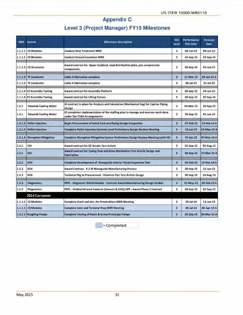
US ITER 1OOOO-MR0110.
Appendix C
Level 3 (Project Manager) FY15 Milestones
1.1.1.1 CS Modules Conduct Heat Treatment MRR 3 02-Jun-15 09-Jun-15
1.1.1.1 CS Modules Conduct Ground Insulation MRR 3 24-Sep-15 23-Sep-15
1.1.1.2 CS. Structures Award contract for Upper keyblock, load distribution plate, pre-compression
3 30-Sep-15 05-Jun-15 components.
1.1.1.3 TF Conductor cable 3 fabrication complete 3 11-Mar-15 09-Jan-15 A
1.1.1.3 TF Conductor Cable 4 fabrication complete 3 08-Jul-15 31-Jul-15
1.1.1.4 CS Assembly Tooling Award contract for.Assembly. Platform 3 30-Sep-15 24-Jun-15
1.1.1.4 CS Assembly Tooling Award contract for. Lifting Fixture 3 30-Sep-15 25-Sep-15
1.2.1 Tokamak Cooling Water 10 contract in-place for Analysis and Calculation (Mechanical Eng) for Captive Piping
Desi n 3 04-Mar-15 10-Sep-15
1.2.1 . Tokamak Cooling Water 10 completes Implementation of the staffing plan to manage and oversee work done
3 30-Sep-15 Ol-Jun-15 under the TCWS Arrangements
1.3.1.3 Pellet Injection Begin Procurement of Initial cask and Piping Design Integration 3 27-Feb-15 13-Feb-15 A
1.3.1.3 Pellet Injection Complete Pellet Injection Systems level Preliminary Design Review Meeting 3 13-Jun-15 13-May-15A
1.3.1.4 Disruption Mitigation Complete Disruption Mitigation System Preliminary Design Review M eeting (with 10) 3 07-Jan-15 07-Nov-14A
1.5.1 ICH Award contract for DC Breaks Test Article 3 02-Sep-15 03-Aug-15
1.5.1 ICH Award contract. for Tuning Stub. and Drive Mechanism Test Article Design and
3 30-Sep-15 27-Mar-15 A Fabrication
1.5.2 ECH Complete Development of Waveguide Interior Visual Inspection Tool 3 25-Feb-15 15-Dec-14 A
1.5.2 .ECH Award Contract. - 4.2. M Waveguide. Manufacturing Process 3 30-Sep-15 22-Jun-15
1.5.2 .ECH Technical Pkg to Procurement-. Polarizer Pair. Test Article Design 3 30-Sep-15 24-Aug-15
1.5.3 Diagnostics PPPL. - Diagnostic Shield Module - Contract Award Manufacturing Design Studies 3 01-May-15 20-Feb-15 A
1.5.3 Diagnostics PPPL - Vislble/lnfrared Cameras (Sensors & DAQ). UPP -. Award Phase 2 Contract 3 30-Sep-15 02-Sep-15
1.1.1.1 CS Modules Complete Stack and Join, He. Penetrations MRR Meeting 3 30-Jul-14 11-Jun-15
1.1.1.1 CS Modules Complete Joint and Terminal Prep MRR Meeting 3 30-Jul-14 08-Apr-15 A
1.3.1.1 Roughing Pumps Complete Testing of Roots & Screw Prototype Pumps 3 23-Sep-14 09-Mar-15A
= Completed
M ay 2015. 31

Department of Energy ORNL Site Office
P.O Box 2008 Oak Ridge, Tennessee 37831-6269
August 7. 2015
MEMORANDUM FOR Dl~U~~ (\ j
FROM : DA~A~~ FEDERAL PROJECT DIRECTOR
U.S. CONTRIBUTIONS TO ITER PROJECT
SUBJECT: U.S. ITER PROJECT MONTHLY REPORT - JUNE 2015
Attached for your information Is a copy of the project's Monthly Report for June 2015. Cumulative cost and schedule earned value performance indices for the month were 0.99 and 1.0, respectively. Ten Project Change Requests (PCRs) were processed during June and these PCRs are summarized in Appendix B of this report. There were three Level 2 milestones and three Level 3 milestones, which were completed during June. Each of the completed milestones is listed with a summary of milestone status on page 8 of the report.
Key activities in June included the continued installation of equipment , manufacturing readiness reviews for the Heat Treatment Station and for the Stack & and Join/Helium Penetrations Station, and commissioning activities for the remaining Central Solenoid (CS) fabrication stations at General Atomics. Fabrication of first article CS Structure tie plates continued, as well as, pre-fabrication activities for CS Structure Lower Key Block componen ts. In addition, a subcontract was awarded for fabrication of CS Structure Upper Components. The St eady State Electrical Network 22kV Switchgear (Lots 1 and 2) were delivered this month. Fabrication of Toroidal Field Conductor continued and an arrangement was signed with the ITER Organization for integration of the remaining production unit lengths. Research and development and design activities continued for the Pellet Injection System, the Disruption Mitigation System, Diagnostics, and Ion Cyclotron and Electron Cyclotron Transmission Lines.
If there are any questions or additional information is required, please contact me at (865) 576-2667 or David Myers at (865) 576-5629.

DISTRIBUTION -2-
SUBJECT: U.S. ITER PROJECT MONTHLY REPORT - JUNE 2015
Attachment
Distribution w/attachment: J. Steve Binkley, SC-21 Kin K. Chao, SC-28 Casey R. Clark, SC-28 Patricia M. Dehmer, SC-2 Michael L. Knotek, S-4 Joseph J. May, SC-24.1 Stephen W. Meador, SC-28 Edward J. Stevens, SC-24.2 Edmund J. Synakowski, SC-24 Sotinos Thomas, S-4 Thomas J. Vanek, SC-24.l Brian D. Huizenga, MA-50 Scott Cannon, NNSA Jeffrey Makiel, PPPL David K. Arakawa, SC-OSO Michele G. Branton, SC-OSO William C. Cahill, SC-050 Daniel K. Hoag, SC-OSO Johnny 0 . Moore, SC-OSO
Distribution w/o attachment: Dina 0 . Clark, ORNL Suzanne A. Herron, ORNL Ned R. Sauthoff, ORNL
A ugust 7, 2015

I -I
i a:
I
us Contributions to ITER
Lower key block for the central solenoid magnet structure durmg forging operations al Scot Forge in Spring Grove, IL
Suzanne A Herron US ITER Deputy Pro1ect Manager
Date 1 ( ~ \ \bS .-==---- --

This report was prepared as an account of work sponsored by an agency of the United States
Government Neither the United States Government nor any agency thereof, nor any of their employees, makes any warranty, express or implied, or assumes any legal liability or responsibility for the accuracy, completeness, or usefulness of any information, apparatus, product, or process disclosed. or represents that its use would not Infringe privately owned rights. Reference herein to any
specific commercial product, process, or service by trade name, trademark, manufacturer, or otherwise,
does not necessanly constitute or imply its endorsement, recommendation, or favoring by the
United States Government or any agency thereof The views and opinions of authors expressed herein do not necessarily state or reflect those of the United States
Government or any agency thereof
Prepared by OAK RIDGE NATIONAL LABORATORY
Oak Ridge, Tennessee 37831-6283 managed by
UT-BATTELLE, LLC for the
US DEPARTMENT OF ENERGY under contract DE-AC05-000R22725

US ITER 10000-MR0111
United States (US) Contributions to ITER
ITER 1s a unique international scientific collaboration representing more than half of the world's population The ITER Members will design, build, and operate a first-of-a-kind international research facility in Cadarache. France aimed at demonstrating the scientific feas1b1hty of fusion energy This is the next step in establishing fusion as a practical long-term energy source, with acceptable environmental characteristics (no greenhouse gas em1ss1ons and no long-lived radioactive waste) and using abundant, readily available fuel (deuterium from water)
The US is to provide 9.09% of the ITER hardware components (by value) and cash equivalent to 9.09% of the international organization budget (for common expenses such as hardware assembly and installation). -80% of US funding will be utilized for the hardware components This funding will not only contribute to state and regional economies, but will enable US industry, universities, and labs to remain at the forefront of fusion technology and engineering. The US industries also benefit from the ITER Project by securing contracts from other ITER domestic agencies (DAs). Additionally, for its 9 09% contribution, the US will have access to all the scientific data and the right to propose and carryout experiments, which will enable the US to achieve its ITERrelated goals in fusion science and fusion technology
The ITER Members are China (CN), the European Union (EU), India (IN), Japan (JA), South Korea (KO), the Russian Federation (RF), and the US The legal framework for construction, operation, deactivation, and decommissioning 1s contained in the ITER Joint Implementation Agreement (JIA), which entered into force in October 2007 The US ITER Project is a collaboration of US Department of Energy (DOE) laboratories, Oak Ridge National Laboratory (ORNL), Princeton Plasma Physics Laboratory (PPPL), Savannah River National Laboratory (SRNL) assisted by univers1t1es and industries around the country
As shown below, the US Hardware contnbut1ons are highly integrated around the Tokamak Core.
Tokamak
Cooling Water
Sys tom
Tokamak Exhaust
Processing Sys tom
(not shown)
Diagnostics
June2015 3
ECH Transmission
Lines
ICH Transmission
LI nos
75% of Steady Stato
Electrical Networi<
(not shown)
8°k of TF coil Conductor
BlanketJShield
Pellet Injection System
Disruption Mitigation (cappod contribution)

US ITER 10000- MR0111
Project progress as of June 2015 is shown below·
R&D
Design
Prl'p lor fabrica11on
f abncat iOn 9"
8"
lO"'
Percent Complete by Phase
US ITER Project
511"4
S/%
b<X
• Planned
• Complcre
8°" 100'4 Vanatlon In bar length due to rounding
The following graph shows the CosVSchedule Performance Indices based on earned value (against the early finish schedule). The overall performance indices remain steady as the cumulative Schedule Performance Index (SPI) for the Project is 1.00 and the cumulative Cost Performance Index (CPI) is 0.99. Each index 1s well within the accepted range.
U.S. ITER Project Cosl/Schodule Perlormance Index Chan (Curoolllive Deta)
1.2
1.0 - -- - ---
u Prlo1 Ott·U NOY·1' o. •. ,. J .... 15 ,.,,.,, MM·15 Apt· IS M>y· ll Jun· IS Jul·11 A~g·11 S•p·11
I- CPI O.ff on Off O.tt OH o.n Ott O.H O.H Ott
1- SPI 0 t7 O.N O.H O.H 0.98 0.11 1 00 1.00 1.00 1.00
June2015 4

US ITER 10000-MR0111
The Project's actual costs and commitments through June 2015 compared to the obligation plan are provided in the following graph.
(b)(5)
Upddted Obligation Plan renens current forecast
June2015 5
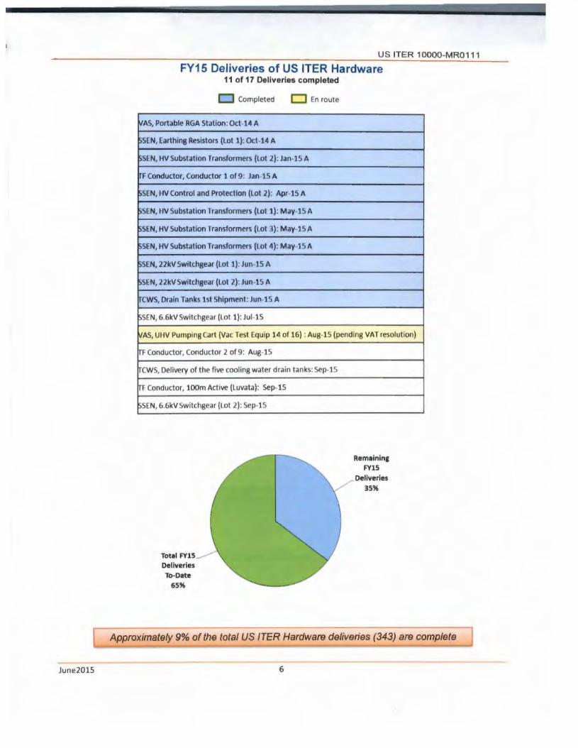
US ITER 10000-MR0111
FY15 Deliveries of US ITER Hardware 11 of 17 Oellverios completed
c::J Compleled D Enroule
WAS, Portable RGA Station. Oct 14 A
~SCN, Carthin8 Resistors (lol 1); Ocl-14 A
~Sl.N, HV Substation Transformer~ (lot 2). Jan 15 A
lrF Conductor, Conductor 1 of 9: Jan 15 A
~SCN, llV Control and Protection (lot 2): Apr-15 A
~SL N, I IV Substation I ransformer~ (Loi 1): M.iy 15 A
i>SLN, HV Substation rransformers (lot 3) May-1SA
~SFN, HV Substation Transformers (lot 4): M;iy 15A
$SCN, 22kVSwitchge.lr (Lot 1): Jun-15 A
l)SlN, 22kVSw1tch8ear (lot 7): Jun-15 A
ITCWS, Drain Tanks 1st Shipment: Jun 15 A
~SEN, 6 6kV Switchgear (lot 1 )· Jul 15
WAS, UHV Pumping cart (Vat Test Equip 14of16) Aug 15 (pending VAT resolution)
TF Conductor, Conduttor 2 of9: Aug·15
TCWS, Delivery of the five cooling water drain tanks Sep 15
Tr Conductor, 100m Active (Luvata): Sep~lS
SSCN, 6.6kV Switchgear (Lot 2): Sep-15
Tot•I FY15
Deliveries To-D•te
65"
Rem1lnln1 FY15
Oellverles
35"
[ Approximately 9% of the total US ITER Hardware deliveries (343) are complete
June2015 6

US ITER 10000-MR0111
Key Activities This Month
Steady State Electrical Network (SSENJ
All of the 400kV substation equipment (HV Substation Transformers, HV Circuit Breakers, HV Switches, HV Current Transformers, HV Potential Transformers, HV Surge Arresters, HV Substation Hardware, Earthing Resistors, and the HV Control & Protection) has been delivered to the ITER site.
The 22kV Switchgear (Eaton Corporation, Cleveland, OH, USA, factory in Hengelo, Netherlands) was delivered, with Lot 1 going to the ITER site and Lot 2 to a site in Spain where it will be installed into prefabricated substation containers by a subcontractor to the European Union (EU) Domestic Agency.
Central Solenoid (CS) Modules and Structures
Manufacturing readiness reviews (MR Rs) and final design reviews continue for the module workstations at General Atomics (GA). The Heat Treatment and Stack & Join - He Penetrations MRRs meetings were completed this month.
A contract was awarded for the fabrication of the CS Structure Upper Components.
Toroidal Field (TFJ Conductor
An arrangement to transfer the scope for integrating up to six of the remaining production unit lengths to the International Organization (10) was signed this month in order to meet the European Union (EU) Domestic Agency (DA) schedule for TF coil winding.
Tokamak Cooling Water Systems (TCWSJ
Fabrication of the remaining tanks is nearing completion with preparations for transportation scheduled for completion by July 24, 2015.
The 10 completed implementation of the staffing plan to manage and oversee work done under the TCWS Arrangements.
Pellet ln/ection (Pl)
A preliminary design review was held at the International Organization (10) for the ex-vessel flight tube sections of the pellet injection system.
June2015 7

US ITER 10000 MR0111 ~~~~~- -~~
Milestone Status
Thirty-three milestones were selected and approved for incorporation into the US ITER FY15 Performance Plan The Plan was reviewed/concurred by the Federal Project Director {FPO) and has been reviewed and approved by OOE-FES
Three Level 2 {DOE Federal Project Director) and three Level 3 (Project Manager) milestones were completed this month
• CS Modules ) Conduct Heat Treatment MRR (L3)
• CS Structures o Award contract for Upper keyblock, load d1stribut1on plate, pre-compression components (L3)
• TCWS
• SSEN
Develop a resource-loaded schedule for completion of the Final Design, mcorporatmg the design solution for the gamma radiation issue (L2) 10 completes 1mplementat1on of the staffing plan to manage and oversee work done under the TCWS Arrangements (L3)
Packaged and ready to ship - 6 6kV Switchgear - Lot 1 (L2) Packaged and ready to ship - 22kV Switchgear - Lot 2 (L2)
Nine of the remaining 15 milestones are forecast to complete on or ahead of schedule The other six, except for one, are forecast to complete by the end of the FY
The following table provides an overview of the milestone status by Level.
Total
Completed 18
°" ......... I
Forecasted Late 4
Lite 2
TOTAL 33
June2015 8
FY15 Performance Plan
u
3
. -1
4
l2
5
2
3
-10
Ll00£fUmluU DOEFPOmll-
L3
10
7
1
1
19
Ll ORNL PrOjK'I ... _ mlls-

U S ITER 10000 M R0111
Contents
WBS 1.1.1 Magnet Systems - Oak Ridge National Laboratory (ORNL) Page 10 Central Solenoid (CS) Modules, Structure, and Assembly Tooling Toroidal Field (TF) Coll Conductor
WBS 1.2.1 Tokamak Cooling Water Systems (TCWS) - ORNL Page 14
WBS 1.3.1 Vacuum Pumping & Fueling Systems - ORNL Page 16 Roughing Pump (RP) Sets Vacuum Auxlllary Systems (VAS)
Pellet Injection (Pl) Disruption Mitigation (OM)
WBS 1.3.2 Tokamak Exhaust Processing (TEP) Savannah River National Laboratory (SRNL) Page 19
WBS 1.4.1 Steady State Electrical Network (SSEN) Princeton Plasma Physics Laboratory (PPPL) Page 20
WBS 1.5.1.1 Ion Cyclotron Heating (ICH) Transmission Lines - ORNL Page 21
WBS 1.5.2.1 Electron Cyclotron Heating (ECH) Transmission Lines - ORNL Page 22
WBS 1.5.3 DlagnostJca - PPPL Page 23
WBS 1.6 Project Support - ORNL Page 24 Procurement Human Resources
Quality Assurance
WBS 1.7 International Organization Support (Secondee and Cash Contributions) - ORNL
Cash Payments Secondees/Employees Total Credit Earned
WBS 1.8 Supplemental Task Agreements (TA) with the 10
WBS 1.9 Instrumentation and Controls (l&C)
Appendix A - US ITER Project Schedule
Appendix B - Project Change Requests processed this month
Appendix C - Level 3 (Project Manager) FY15 Miiestones
June201S 9
Page 25
Page 27
Page 28
Page 29
Page 30
Page 31

US ITER 10000 MR0111
WBS 1.1.1 Magnet Systems - Oak Ridge National Laboratory (ORNL)
Central Solenoid (CS) Modules and Structure - Requi red for ITER 1•1 Plasma
The US 1s responsible for the CS magnet, including design, R&D, and fabrication of six CS modules (coils) and a spare module using supplied cable-in-conduit superconducting conductor (from JA), the vertical precompress1on structure, Assembly Tooling (AT). bus extensions. and cooling connections.
The CS serves as the backbone of the ITER magnet system The CS induces the maiorrty of the magnetic flux change needed to initiate the plasma, generate the plasma current. and maintain this current during the burn time.
General Atomics (GA) in San Diego, Cahforn1a, has been awarded a maior contract to fabricate the modules of the CS.
Preparations for CS Modules, CS Structure and Assembly Tooling fabrication continue
WBS 1.1.1.1 - CS Modules
The Helium Inlet Design Analysis Calculation was approved by the 10 this month. The analysis calls for peening of the toe of the weld to achieve the required cyclic fatigue life Post-peened, heat treated weld samples were sent to the High Flux Isotope Reactor (HFIR) for nondestructive measurement of the residual stress as a function of depth using neutron spectroscopy Results are expected next month
Module fabrication at GA is proceeding:
• Station 2 - Winding
Winding of the first production module hexapancake T1 has restarted
As of June 30, four of the six layers have been completed
• Station 3 - Joint and Terminal Prep
The short lead breakout welds on the Mockup T1 hexapancake have been completed and leak checked.
The mockup T1 hexapancake will be moved to station 4 early 1n July.
• Station 4 - Stack and Join
Comm1ss1oning of Station 4 was completed and MRR1 was conducted
Documents which were in draft status at the MRR are being approved to satisfy the only category 1 chit in preparation for the start of processing the mockup.
June2015 10
• Station 5 - Heat Treatment Furnace
Commissioning of Station 5 was completed and MRR1 was conducted.
Documents which were in draft status at the MRR are being approved to satisfy the only category 1 chit in preparation for the start of processing the mockup
• Station 6 • Turn Insulation
Comm1ss1oning activities are well underway for Station 6.
, A demonstration of the conductor lowering system and the manual insulation of the first three turns was demonstrated.
The Ridgway wrapping heads have been installed and have been operated to apply the turn insulation integrated with the conductor lowering system
The latest delivery of quench detection tape 1s being tested in the wrapping heads to determine tape acceptability
• Station 7 - Ground Insulation
A Final Design Review was conducted at the end of the month There were no category 1 chits.
GA has discovered that the insulation of the quench detection 5 kV and 30 kV wires is susceptible to cracking due to two

phenomena:
• The resin can permeate between the insulation and wire over a long distance to the point that wires protruding from the ground insulation are no longer flexible and will crack easily.
• Resin that cures on the outside of surface of the Insulation Is brittle and will crack causing the underlying wire insulation to crack as well.
GA is working on several methods to seal the wires from contact with the resin. The T1 lead breakout VPI test is on hold until a better wire seal is developed.
• Station 8 - Vacuum Pressure Impregnation
c A second Final Design Review was conducted at the end of the month to review the design and installation of the outside diameter compression panels that are installed at this station.
Pneumatic wrapping head is supported by a beam for the turn insulation station at General Atomics
US ITER 10000-MR0111
A test of a prototype compression panel was completed.
<• Techniques for collecting metal chips and G10 debris were tested. Lessons learned were captured and improved techniques are planned.
• Station 9 - Helium Piping & Measurement
o No activity
• Station 10 · Final Test
c A final design review of the integrated Final Test Station was conducted early this month.
The warm bus bars have been delivered.
n The He Gas tanks were delivered and installed on the pad adjacent to the Butler building.
Begin wlndlng the first central solenoid module 14 Apr-15 23-Mar·lS A
Conduct Turn Insulation MRR 2 02-Jul-15 24·AU&·1S
Due to a delay In the receipt of parts needed to complete the Heat
Treatment acceptance test, which delayed the handover of the 2
layer coll to Station 6. Commlslonlng time was also Increased due
'--------------..___..__ ___ ...._ __ _. .... to_a_h...,I h-'e ___ r technltal C.!!!!!f>le!!!Y.:......
•Completed • On-Schedule • Forecast to Miss PP Date =Missed PP Date
June2015 11

WBS 1.1.1.2 - CS Structures
Pre-fabrication activities continued at Petersen, Inc. for manufacturing the Lower Key Block Assembly Petersen is in the process of preparing procedures for welding, material handling, helium leak testing, and cryogenic shock testing.
Two fabricators, Major Tool and Machine (MTM} and Precision Custom Components {PCC}, are now underway to fabricate first article outer tie plates
• MTM submitted procedures for visual Inspection and dimensional inspection for review and approval.
• MTM submitted a deviation request to use phased array ultrasonic testing in lieu of conventional radiographic inspection for the tie plate structural weld inspection.
• MTM continues to work on designs for tie plate tooling fixtures and will present those designs when complete
CS Structures
US ITER 10000 MR0111
• PCC's manufacturing and inspection plans (MIP) were reviewed and approved by both the USITER and the 10 for the manufacturing of the first article tie plate and the weld qualification demonstration for attaching the cooling pipes to the tie plate.
• PCC's tie plate Nitronic 50 ingot was approved for forging .
A contract was awarded to Hamill Manufacturing for the fabrication of the CS Structure Upper Components. This fabrication effort includes most CS structure components at the top of the central solenoid
The statement of work (SOW) and drawings have been completed for procurement of the multi-jackbolt-tensioners (MJT) which are components of the CS structure pre-compression system.
MS Pl'rform,1nce Fo1ec.1s1 Milestone Dl'script1on I evrl Pliln Dair Dair Comments
·---=Completed =On· Schedule
WBS 1.1.1.4- CS Assembly Tooling (AT)
Final preparations for the Lifting Fixture follow-on Final Design Review were completed and the review was held via videoconf erence with the 10 Review Panel
• The revised design was well received as all Review charges were answered.
• A Final Report was received with 14 chits, none of which are Category 1.
Other work scope accomplished included.
June2015 12
=forecast t.o Miss PP Date =Mlssed PP Date
• Work continued on remaining fixture designs in preparation for AT FDR-2
• Design of the bus bar support fixture continued and a presentation was made at the interface meeting.
• 30 models of the drill guide fixture have been completed and will be the final remaining fixture to be presented at the interface meeting in mid-July to discuss and confirm the interface requirements between the shear pin and CS module

US ITER 10000-MRO 111
Toroidal Field (TF) Coll Conductor- Required for ITER 111 Plasma
The US will contribute 8% of the TF coil conductors The 10 is responsible for the conductor design which 1s released for fabrication JA. EU. RF. KO. and CN are also contributing TF conductor
The 18 TF coils produce a magnetic field around the ITER tokamak torus to confine the plasma particles The US 1s responsible for enough conductors to wind slightly over one TF coil
The coils will be made of cable-in-conduit superconductors. In which a bundle of superconducting strands 1s cabled together. compacted into a stainless steel conduit. and cooled by supercritical helium
Luvata Waterbury (Waterbury, Connecticut) and Oxford Superconducting Technologies (Carteret, New Jersey) have been awarded maJor contracts to produce TF strand. New England Wire Technologies (Lisbon, New Hampshire) received the contract for cabling the strand and High Performance Magnetics (Tallahassee, Florida) will perform the conductor integration/jacketing
Fabricatlon of TF Conductor continues
WBS 1.1.1.3 - TF Coil Conductor
Fifth stage cabling of the second 100 m Luvata qualification length was completed at New England Wire (NEWT) Three improvements were suggested to improve the process
At High Performance Magnetics (HPM). packaging of the second production unit length was completed (OST 8) Cable insertion. compaction. and spooling
Packaged •nd ready to ship first 760m conductor to EU 1
of the third production unit length (OST C) were also completed
An arrangement to transfer the scope for integrating up to six of the remaining production unit lengths to the 10 was signed this month The arrangement was necessary in order to meet delivery date commitments to the EU DA, who is responsible for TF Coil winding.
10-Jan-15 20-0ct-14 A
Packaged and ready to ship luvata lOOm to EU 2 17-May-15 12-Mar-15 A 1--~~~~~~~~~~~~~~~~-+~-+-~ ~~~+.--~~~~~~~~-!
2nd 760m Conductor packaeed 2 22-Sep-lS Ol-M-U L...--~~~~~~~~~~~~~~~~--L~---'-
=Completed =On-Schedule • = Forecast to Mss PP Date =Mssed PP Date
June201S 13

US ITER 10000-MR0111 ----WBS 1.2.1 Tokamak Cooling Water Systems (TCWS) - ORNL
TCWS - Portions of the system required for ITER 111 Plasma
The US is responsible for the design, engineering, and procurement of TCWS.
ITER's fusion power will reach 500 MW during the deuterium-tritium Inductive plasma operation with an energy input of only 50 MW, yielding an energy multiplication factor of 10. Heat will be transferred by the TCWS from client systems to the environment through the secondary cooling system. TCWS 1s designed to cool client systems, such as the first wall/blanket, vacuum vessel, divertor, and neutral beam injector (NBI). Additional operations include baking of in-vessel components, chemical control of water provided to client systems, draining and drying for maintenance, and leak detection/localization
The TCWS interfaces with the majority of ITER systems, including the secondary cooling system, which rejects this heat to the environment Plasma operations are inherently safe because a functioning cooling water system is not required to ensure safe shutdown.
System Design and Fabrication of the remaining three (of five) Drain Tanks continue
Design
Progress on the design of the TCWS continues while the 10 also pursues the services of outside engineering service providers. These other activities include:
• Optimization of the Vacuum Vessel Primary Heat Transfer System (W PHTS) using Fathom fluid modelling. The previous W PHTS design removed 10 MW while the current designed thermal load has been determined to be 32 MW. The Fathom analyses report was modified to address comments from US ITER subject matter experts (SME).
• Other ITER systems, and other portions of the TCWS, are Impacted by the Integrated Blanket ELM Divertor (IBED) redesign and require additional design resources to address issues such as physical clashes with other piping or equipment, available space for the conduct of maintenance, and design interfaces with systems served by the TCWS.
Fabrication of Drain Tanks
Normal Drain Tanks 2A (NDT2A) and 2B (NDT2B) were previously delivered to Cadarache and are currently in the storage building specifically designated for all of the TCWS Drain Tanks until installation.
Fabrication of the remaining tanks Is nearing completion with preparations for transportation
June2015 14
• TCWS completed two key Performance Plan milestones this month. o Develop a resource-loaded schedule for
completion of the Final Design, mcorporatmg the design solution for the gamma radiation issue (L2) Detailed activities were established and resource loaded to address the gamma radiation issue and incorporate the design option approved by the DG In April 2015.
,.., 10 completes implementation of the staffing plan to manage and oversee work done under the TCWS Arrangements (L3) - The 10 has successfully completed the Implementation of the staffing plan with twenty three staff currently on-board and two more having accepted offers with a start date in September.
scheduled for completion by July 24, 2015. The status as of late June Is:
• Neutral Beam Injection Tank (NBl3) - Final visual inspection after external passivation identified local areas to remediate.

• Safety Dram Tank 1A (SDT1A) - Deficiency Notice for Shrink Wrapping has been approved and final act1v1ties to occur into early July
• Safety Drain Tank 2A (SDT1B) - Internal pass1vat1on and wet water testing completed
TCWS
Delivery of the five toollnc water drain links to pon In Fr1nce co111Plet1
Develop 1 r11ource·lolded schedule for completlon of the Final Deslsn.
lncorporatlnc the de1l1n solution for the 1wnm1 r.cllatlon tuue.
ID Awards Framework contract for TCWS Plplncs & Flttinp
2
U S ITER 10000-MR0111
Transfer of ownership from US ITER to the 10 1s planned when the tanks are loaded on the ship m late July or early August
ll May·lS OS·Jun·lS A
31-Jul· lS 2S·Sep IS
manufltturer not rHdy· to-thlp. 1st dr1ln tank shipment has been received at ITTR. 2nd shipment
rud · to-sht d"t: Jul 24.
The contract c.annot be placed prior to final plplnc confl1unitlon. Desl1n modification of IBED PHTS to addreu radl11lon shleldlnc luue needs updllH on
'----------------------'--'-----....__ ___ ..i.rlpl"l..!!Lout Ind thus Tech Sp!c.
June2015 15

US ITER 10000-MR0111 ---WBS 1.3.1 Vacuum Pumping & Fueling Systems - ORNL
Roughing Pump Sets - A portion of the components required for ITER 1•t Plasma
The US will contribute 100% of the ITER roughing pumps
The ITER tokamak, cryostat, and auxiliary vacuum chambers must be evacuated prior to and during operations The roughing pump system exhausts the torus and NBI cryopumps, service vacuum, and cryostat. This system will utilize a matrix of pump trains with various technologies to match specific vacuum system requirements, including tritium-compatible backing pumps for torus and neutral beam cryopumps
Support to the 10 for Conceptual Design continues
WBS 1.3.1.1 - Roughing Pump Sets
The test data from the initial round of CVC performance testing in the Spallation Neutron Source (SNS) Cryogenic Test Facility (CTF) continues to be analyzed to determine what detail adjustments are needed to achieve the desired performance during the next window of opportunity for testing which is now projected to be in October - November 2015.
The revision of the Task Agreement for the tritium compatible prototype Roots and Screw Vacuum
pump train to include the test stand as a deliverable was approved. The pumps were shipped to the 10 this month and the test stand was packaged for shipment to the 10.
Additional results of the performance testing of an alternative tritium compatible roots pump stack at Oerlikon/leybold were provided to the 10.
Vacuum Auxlllary System (VAS) - A portion of the system required for ITER 111 Plasma
The US will design and procure the ITER vacuum auxiliary system.
The vacuum auxiliary system consists of valves, pipe manifolds, auxiliary pumps, sensors, and controls. The torus and NBI vacuum manifolds of this system need to be tritium compatible.
The Vacuum Auxiliary System Procurement Arrangement 3.1.P4.US.01 (designated as VAS-01 ) scope includes the design and procurement of those components associated with the vacuum piping which serve as the manifolds providing vacuum service throughout the Tokamak Building.
The Vacuum Auxiliary System Procurement Arrangement 3.1.P4.US.02 (designated as VAS-02) scope includes the design and procurement of those vacuum components which connect the vacuum manifolds provided in VAS-01 to the clients (ITER technical systems) requiring vacuum service throughout the Tokamak Building.
Design continues and preparations for fabrication have begun
WBS 1.3.1.2- Vacuum Auxiliary Systems (VAS)
Design VAS-01 Scope:
The 10 signed the VAS-01 Part 1 FDR Closeout Report completing the review.
Final design and analysis of the VAS-01 piping systems on levels L 1 and L2 continue to progress.
June2015 16
while the design of the piping systems on levels L3, L4 and LS remain on-hold pending the finalization of changes associated with PCR-662 (ITER water activation issue)

Fabrication VAS-01 Scope:
The Vacuum Piping Centralization procurement package from the 10 was posted for a commercial ·call for Nominations· The procurement packages related to the supply of the piping vacuum flanges,
VAS
US ITER 10000-MR0111
custom pipe supports and clamshell leak test fixtures were reviewed by the 10 and final comments are being addressed
MS Pl'rformdne<• Forec.ut Mill'\!one DeHropt1on Comment\
lrvf'I Pl.in OdtP D•tr
10 PCR·662 has resulted In
Complete VAS· Ol FOR (U· l4) 2 30-Sep-15 30-Mer·16 modlflcatlons to fadllty and vacuum
equipment configurations
=Compftttd • On·Sdltdult
Pellet Injector (Pl) System - A portion of the ayatem required for bulldlng Integration prior to ITER 111
Plasma
The US will design and procure the Pl system
Pl provides efficient core and edge fueling and will deliver hydrogen, deutenum, or a deuterium/tritium mixture as required by plasma operations Dehvenng fuel pellets to the plasma edge m1t1gates ELM (edge localized mode) instabihtles
R&D and Preliminary Design Activities continue
WBS 1.3.1.3 - Pellet Injection
A preliminary design review was held at the 10 for the ex-vessel flight tube sections of the pellet injection system The review resulted in no category 1 chits and 6 category 2 chits The flight tubes transport the pellet injection cryogenic pellets from the Pellet Injection System into the vacuum vessel.
Manufacturing issues with vacuum leaks at brazed joints for the twin screw extruder continue to persist, which is preventing the laboratory testing of the latest iteration of the extruder design Resolving this issue is the primary focus It 1s expected the leak issues will be resolved m July with testing resuming in August
Disruption Mitigation - System not required for ITER 1•1 Plasma
The US will contribute up to a capped value for the D1srupt1on M1tlgatJon System (OMS) The system has two functions, 1} hmrting the impacts of plasma current disruptions to the tokamak vacuum vessel, first wall blankets and other in-vessel components and, 2) suppressing the formation and deleterious effects of highenergy runaway electrons Out of port plug installation of shattered pellet injection (SPI) units at four port locations that are designed to also function as massive gas injection (MGI) units 1s the current plan for the OMS In addition, an option for an MGI unrt within a port plug 1s included This unit is to be designed to function during non-nuclear operations only to provide operational experience of a fast acting MGl unit close to the plasma
June2015 17
US ITER 10000-MR0111
Preliminary Design Activities continue
WBS 1.3.1.4 - Disruption Mitigation
Studies are ongoing to characterize the performance of various valve sizes and propellant loads for accelerating a 24.4 mm diameter d1srupllon mitigation neon cryogenic pellet. Preliminary findings are showing a lower limit of 16 mm diameter on the valve orifice before pellet speed is impacted. These results potentially allow for the minimization of the propellant valve size, which is desirable as a smaller valve orifice will have better sealing performance, reduced current required for operation, and greater operating speed. Studies continue to determine the ideal gas load to maximize pellet speed without injecting excess unwanted propellant gases.
Hardware to perform cyclic testing on the massive gas injection (MGI) valve has been received and is
June2015 18
being assembled The hardware allows for the continuous cycling of the MGI valve for endurance studies over an extended period of operation Testing Is expected to begin in September.
Work continues to integrate the disruption mitigation system into the port plugs. Design focus is on the penetrations through the Diagnostics First Wall and the port plug closure plate. Concepts have been developed, and are being Incorporated into the 30 models and discussed with the port plug integrators.

US ITER 10000- MR0111
WBS 1.3.2 Tokamak Exhaust Processing (TEP) - Savannah River National Laboratory (SRNL)
TEP - System not required for ITER 111 Plasma
The US ts responsible for the Final Design (FD) fabrication assembly, testing, and shipment of the TEP system
ITER will require the processing of an unprecedented rate of hydrogen isotopes To facilitate environmental respons1b1hty and economic application of fusion technology, the reuse of hydrogen isotopes 1s vrtal. The TEP system must separate the exhaust gases into a stream containing only hydrogen isotopes and a stream containing only non-hydrogen gases. The implementation of the TEP system will provide a technically mature, robust, and cost-effective separation solution.
The TEP system consists of a series of filters, catalysts, and permeators (PM) to separate the hydrogen Isotopes, which are then sent to an isotope separation system (furnished by the EU) to deliver deuterium and tritium for continuous reinject1on into the reactor.
Support for Preliminary Design Activities continues
Preliminary design 1s the responsibility of the 10 A Task Agreement (TA) to the US delineates the part of the design to be performed by US ITER TEP Team
The team continued activities for the design studies for Subtask-2 of the TA (Functions, Requirements, Interfaces and Scenarios) and initiated activities for Piping and Instrumentation Diagrams (P&IDs) development
June2015 19
Currently, the US TEP design team is approximately 65% complete with Subtask-2 TEP Process Studies Final input parameters for the studies were received from the 10 in June All studies were drafted and are 1n internal review.
Sample P&IDs were developed for 'review of concept' to enable the 10 to determine the level of detail expected for TEP preliminary design P&IDs.

US ITER 10000-MR0111
WBS 1.4.1 Steady State Electrical Network (SSEN) - Princeton Plasma Physics Laboratory (PPPL)
SSEN - Hardware required for ITER 111 Plasma
The US contributes 75% of the equipment required for the SSEN, excluding cables and emergency power. The EU contributes the remaining equipment and 1s also responsible for the design and installation of the system as well as all cabling and all emergency (diesel generator) power systems.
The SSEN is an alternating current (AC) power substation and distribution system that supplies electrical power to all ITER conventional systems and facilities. A separate system delivers power to the pulsed systems, including the magnet and heating power supplies.
The SSEN Is rated at 120 MW and ls similar to the auxiliary power distribution system in a nuclear fission power plant, except that it is about twice the size. The equipment to be contributed by the US is typical of a large AC power distribution system, consisting of transformers and switchgear at the high-voltage (400 kV) and medium-voltage (22 kV) levels.
Hardware Procurements and Shipments continue
All of the 400kV substation equipment (HV Substation Transformers, HV Circuit Breakers, HV Switches, HV Current Transformers, HV Potential Transformers, HV Surge Arresters, HV Substation Hardware, Earthing Resistors, and the HV Control & Protection) has been delivered to the ITER site. The final Delivery Reports and transfer ownership of site support and warranty are being processed for these items. The 400kV substation equipment amounts to 36% of the total credit for US in-kind contributions to the SSEN.
The 22kV Switchgear l(b)(5) I l(b)(5) I was shipped and delivered, with Lot 1 going to the ITER site and Lot 2 to a site in Spain where it will be installed into pre-fabricated substation containers by a subcontractor to the EU DA.
The 6.6kV Switch ear (b)(5)
SSEN
was 1ppmg approval was
The Power Transformers Ub)(5) I l<bl(5) I Design Review chit resolution process is underway. The next step will be to issue a Release for Manufacturing.
A Request for Proposal was issued for the Reactive Power Compensators with a proposal due date in July.
DC Distribution, UPS, and LV Distribution & Subdistribution Panels procurement activities are on hold pending availability of US ITER funding.
In summary: • 12 of 16 contracts have been signed and/or
executed. • Procurement of another item is underway and
the remaining 3 are on hold due to funding constraints.
• 20 of 31 shipments have been completed.
IPL> Dellvery of HV Substat ion Tr•nsformers (lot 4) by US-DA to ITI:R Site 1 27· May-1S 21-M•y-lS A
P1ckt1ed •nd relldy to ship · 6.6kV Swltchaur (lot 1) 2 28· lun·15 26·Jun-15 A -----
Paclulaed and relldy to ship · 22kV Switchgear (l ot 2) 2 16·Jul·15 07-Jun-15 A
%Completed &On·Sdledule • Foreast 10 Mm PP Date •Missed PP Date
June2015 20

US ITER 10000-MR0111
WBS 1.5.1.1 Ion Cyclotron Heating (ICH) Transmission Lines - ORNL
IC Tranamisalon Lines- A portion of the system la required for building integration prior to ITER 1st Plasma
The US 1s responsible for the IC transmission lines, including R&D, design, fabrication, and interfaces The 10 1s responsible for installing the IC transmission lines
The IC system heats the ions in the plasma with a high-intensity beam of electromagnetic (EM) radiation Generators produce high-power radio frequency waves that are carried along multiple transmission lines to antennas located in the vacuum vessel, sending the waves into the plasma The US IC transm1ss1on lines will provide efficient power transfer from 40-55 MHz radio frequency sources to the plasma healing antennas The system will include coaxial transmission lines and a matching/tuning system to minimize power transfer losses The pressurized lines can transmit up to 6 MW per line. In total, approximately 1 5 km of line connects 8 sources to 16 antenna feeds, with 14 types of transmission line and matching system components. The main interfaces include sources, launchers, buildings, port cells, and water cooling. The short coaxial line also provides secondary tritium confinement.
Preliminary Design Activities continue
Intermediate design progress meetings were completed with the vendor teams that are in the first phase of developing designs of 3-meter-long stub tuners All three vendors are making good design progress
Multiple successful 1-hour tests of the ICH transm1ss1on line ·Assembly Bellows" at high-current and at voltages up to 38 kV were conducted on the resonant line test stand at ORNL. The assembly bellows simplifies the installation/removal of multiple sections of ICH transmission line
Multiple discussions were held with the 10 ICH and remote handling teams in response to certain aspects of PCR-664 "Port Cell Rails" proposed for remote handling. As a result of those discussions.
June2015 21
the decision to install or not install permanent port cell rails in the ICH port cells will now be assessed after a period of initial ITER operation. In parallel with those discussions, the US and 10 ICH teams jointly modified layouts for both the double stub and triple stub tuner ICH pre-match options to determine 1f they could be compatible with reduced port cell space hm1tat1ons.
A contract for procurement of vacuum variable h1ghvoltage, high-current tuning capacitor test articles was awarded to COMET Plasma Control Technologies. A total of 36 tuning capacitors are used in the ICH system to adjust tuning and to control power flows.

U S ITER 1 OOOO-MR0111
WBS 1.5.2.1 Electron Cyclotron Heating (ECH) Transmission Lines - ORNL
EC Transmission Lines - A portion of the system is required for ITER 1•t Plasma
The US is responsible for the EC transmission lines, including R&D, design, fabrication, and interfaces. The 10 is responsible for Installing the EC transmission lines.
The EC system heats the electrons in the plasma with a high-intensity beam of electromagnetic radiation. This system is also used to deposit heat in very specific places in the plasma. Power will be provided by powerful, high-frequency gyrotrons. The US transmission llne design will provide efficient power transfer from 170 GHz gyrotron sources to plasma heating power launchers (20 MW).
The transmission lines feature multiple lines of evacuated aluminum waveguides with internal corrugations that can transmit 1.5 MW per line for 3000 seconds, while minimizing power transfer losses to s 10%. Approximately 4 km of transmission line will be part of this system, connecting 24 sources to 56 feeds with 1 O types of waveguide components. The main interfaces include sources, launchers, buildings, port cells, water cooling, and auxiliary vacuum. The waveQuide also provides secondary tritium confinement.
Final Design Activities continue
The Component Cooling Water System-1 (CCWS-1 ), as presently designed, does not accommodate the US and other systems that have copper cooling surfaces. A visit was made to the 10 to advance PCR-634 "Revision of the CCWS-1 in compliance with Client's requirements associated with Copper wetted surfacesn. The US TCWS team assisted by providing detailed water quality requirements that are needed to be compatible with copper cooling surfaces. The TCWS team is working to identify the
June2015 22
footprint and location for the equipment needed for a primary cooling loop for ECH, ICH and Diagnostic systems off of the CCWS-1 loop.
The evaluation of bids for a Basic Ordering Agreement (BOA) for "Process Development and Manufacture of 4.2m Waveguide and Associated Componentsn was completed.

US ITER 1 OOOO-MR0111
WBS 1.5.3 Diagnostics - PPPL
Oiagnoatlcs-Only a few instruments (RGA & LFSR) needed for ITER 1•1 Plasma
The US is responsible for 14% of port-based diagnostic systems, including integration of 4 diagnostic port plugs, plus 7 instrumentation systems out of a total of approximately 40 individual diagnostic systems. The EU, RF, CN, KO, and IN are also contributing to ITER diagnostics.
ITER diagnostic systems provide measurements to aid understanding of plasma behavior and optimize fusion performance. Because of the harsh environment inside the tokamak vacuum vessel, these systems must cope with a range of conditions not previously encountered by diagnostic technology, all while performing with high reliability. US Diagnostics will include microwave, laser, x-ray, and optical systems. The US will provide design, fabrication, assembly, and testing of US port plugs, specifically the Upper Ports (U11 , U17) and Equatorial Ports (E3, E9). In addition, the US will support the integration Into these plugs of multiple diagnostics, including some from other DAs.
The US will also be responsible for the following instrumentation systems: Upper IRNisible Cameras, Low Field Side Reflectometry (LFSR), Motional Stark Effect (MSE), Electron Cyclotron Emission (ECE), Toroidal Interferometer/Polarimeter (TIP), Core Imaging X-ray Spectrometer. and Residual Gas Analyzer (RGA).
R&D and Design continue
Diagnostics staff spent two days with the ECE diagnostic team at University of Texas-Austin (UT) providing structural analysis and ITER design code training.
Staff also provided SOC-IC training for the Upper Wide Angle View Visible IR Cameras team from General Atomics and the Dutch firm TNO in June. The Upper Port Wide Angle View Visible-IR Camera (UPP WAVs) system is US ITER's largest diagnostic project. The UPP WAVs are distributed to five upper port plugs and provide Visible and Infrared views of the divertor and blanket shield modules for machine protection. General Atomics is the subcontractor through final design and has also contracted with Lawrence Livermore National Laboratory (LLNL) for system physics support and the Dutch company TNO for optical and mechanical engineering services. This month a meeting was organized at PPPL that brought together the full technical team from PPPL, GA and TNO. Optical and mechanical engineering details were discussed with the goal of locking in the designs for the early 2017 Preliminary Design Review (PDR).
Diagnostics
A Diagnostics staff member was invited to represent the USDA at a series of technical meetings on the EUDA ITER diagnostics and port plugs. Attending this meeting was important for learning about innovative European design approaches, discussing common ITER requirements issues and checking on EUDA systems that are being integrated into USDA port plugs.
The annual ITER neutronics meeting was held at the ITER site over the week of June 30th to July 3rd and was attended by diagnostics staff. During this meeting, many topics were covered concerning the use of detailed neutronic models, updated neutronic analysis codes, and neutronic benchmarks. The C-lite analysis model has had significant updates and Is being finalized for distribution among the community.
MS Perform.mce Forf'Cil\I M1le\tone De'>cr1pt1on Commenh
level Plan Date Date
---~-=Completed • On·Schedule =forecast to Ml~ PP Date =Missed PP Date
June2015 23
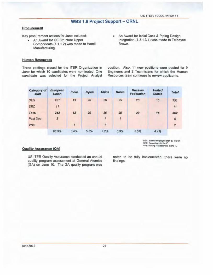
U S ITER 10000-MR0111
WBS 1.6 Project Support - ORNL
Procurement
Key procurement actions for June included: • An Award for CS Structure Upper
Components (1 .1.1.2) was made to Hamill Manufacturing.
Human Resources
Three postings closed for the ITER Organization in June for which 10 candidates were nominated. One candidate was selected for the Project Analyst
• An Award for Initial Cask & Piping Design Integration ( 1.3.1.3.4) was made to Teledyne Brown.
position. Also, 11 new positions were posted for 9 Engineers and 2 Technicians for which the Human Resources team continues to review applicants.
Category of European India Japan China Korea
Russian United Total staff Union Federation States
DES 231 13 20 26 25 20 16 351
SEC 11 11
Total 242 13 20 26 25 20 16 362
Post Doc 3 1 1 5
VRs 1 1 2
66.9% 3.6% 5.5% 7.2% 69% 5.5% 4.4%
DES directly employee! 11an by the 10 SEC Se<ondees to the 10, llRI V11rt111g R111e~ora • the 10
quality Assurance (QA)
US ITER Quality Assurance conducted an annual noted to be fully implemented; there were no quality program assessment at General Atomics findings. (GA) on June 10. The GA quality program was
June2015 24

U S ITER 10000-MR0111
WBS 1. 7 International Organization Support
(Secondees and Cash Contributions)- ORNL
Per the JIA, the US is obligated to contribute 9.09% of the value estimate of the construction of ITER. The contributions are measured in ITER kilo Units of Account (klUA), which has been used by ITER for many years; 1 klUA equals $1 M US dollars (January 1989). The US commitment, 424.618 klUA, includes hardware fabricated/procured by the US, cash for installation and commissioning, staff (secondees or cash for direct employees), and cash for R&D directed by the 10.
The US can also receive credit (klUAs) for performing additional work through approved Task Agreements (TAs). The US will cover its share of the cash contributions through cash payments in current year Euros upon request by the 10. Euros are purchased with current year dollars using the current exchange rate when the payment is due. To establish the klUA value of annual cash contributions, the Euros are de-escalated to Euros (January 1989) using proven inflation rates, and then converted to millions of dollars (January 1989) to yield klUA.
Note the tables below reflect a naw decision not to grant credit for contnbut1ons to the 10 pnor to CY 2007 The Cash Payments Table contains the 2006 cash contnbut1on but the credit does not contain this 2006 value
Cash Payments
Calendar Budgeted € Paid € Paid $
Remalnlng Year Oblleatlon €
2006 409,000 € 409,000 € $528.918.80 0
2007 3,985.000 € 3,985,026.06 € $5,463,231 . 76 0
2009 15,689,630.70 € 15,689,604.64 € $21,102,518.24 0
2010 9,567,409 € 9,567,409 € $13,552,234.85 0
2010 1,577,433 € 1,577,433 € $2.018,010.04
Suoolcmcntal 0
2011 Advance 9,132,173 € 9, 132, l 73 f $11,650,826.31
Pavmcnt 0
2012 9,450,359 € 9,450,359 € $12,133,315.92 0
2013 17,672,925 € 17.672,925 € $23.975,973.67 0
2014 14,885.339 € 14,885,339 f $20,280,343.91 0
2015 13,741 ,328 € 13. 741.328 € $14,827,218.12 0
Cumularf\ie 96, 110,596. 70€ 96, 110,596. 70 € $125,532,591.62 0
Estimated Credit Earned to date: 59.284 kIUA
Average Exchange Rate realized for cash paid = 1.306
June2015 25

US ITER 10000-MR011 1
Secondees/Employees
U.S. Secondccs Credit Earned: 1.53 1 klUAs Current Number of Secondccs: 0
U.S. Direct I !ires Current Number of U.S. Direct II ires: 32 I New I lire starting in August 20 15
Total Credit Earned (- 20% of total planned)
195.790
15.193 12.685 2.508
202.986 59.284 143.702
427.230 85.230 342.000
2007 2008 2009 2010 2011 2012 2013 Cash 2. 711 0 10. 138 13.063 0 5.835 10.645 Secondees .629 .274 .277 .246 .105 0 0 TAs 0 .300 .048 2.284 4.61 1 2.497 1.939 PAs 0 0 0 2.500 0 5.850 0 Total 3.3./0 .574 10 . .J63 18.093 ./. "16 N.182 12 . ./86
2014 2015 Total Cash 8.842 8.050 59.284 Secondees 0 0 l.531 TAs 1.006 0 12.685 PAs 3.380 0 11.730 Total 13.228 8.050 85.230
June2015 26

US ITER 10000 MR01 11 ---WBS 1.8 Supplemental Task Agreements (TA) with the 10
Task Agreements currently in-progress
Crtdll CNClll Rtcelvtd
Amount ID 0... Eapedld
TU - Amnev USContlct ld.IAI 1111.JAI TAStlft Flnlltl Comments
T Me.FT-IJS.RP.0 I 'h. of ~Coni:apu US.flO II. HecNlt Lairy
0 ' 50 01 lll.'20 II OIJ1''201~ llC>llftl"d llUnclmlftl
lien 1ddwdD02I ~UA
C7HD21 ru Neunftla "'•'1111 S..l'l'OlllorlTEA DANt l U olW•c 8 Nel!Oll l DSll ~1/2014 09~15
~·'"11\dlDtnl " 1t11mtd S.•Mt lddld 0 07 HIUA
14fCll'! US.RP.o2 ITER RougllinQ fl,.liJm Cl'\OQllllC \ltCOUI Flow US.IPO
~Ho hltr L""Y 0267 01o1)2J2011 11124/2016
ComDIOUDf o. .. 1nnmen1 Ba~ot
C S5TDl8fU Gt11tnc Diagnoale fn 1 V..Q Plwi'"MlllY•n4 FIN1 Duogn PPPI. V..in16lelloiy
1237 0322 ov.111/2012 03131/2016 Dou•lotu11
ClllDlSFU Cll.eloptntn1orITER0111 "-let - IJ$.l'O D Aum1111111 0 1()0112008 07!2ll2016
TJ.FC 11'1 ·US- IHI 1 Pi."'11nary Dntg11 Tuu IUOQllld .. II PBS 12EP1'11111
SRNL llllNClAOQWt om 11111712013 Da/JIV2017 l~•m
TMCIPI USRP43 l/ddOOll olP1111>11 Pump.,, ITtR Rougll•llg S,.lom 11$!1'0 D<I"" Rt1m1111111 0002 10/11/2012 llQOf.!017 L11rr11tf.ir
loi.IUJA 29'24 0322 iiwo.. s 8 IM 07M
June2015 27
US ITER 10000-MR0111
WBS 1.9 Instrumentation and Controls (l&C)
Centralized Instrumentation and Controls Support. Required for ITER 1" Plasma
The US is responsible to provide l&C for all Procurement Arrangements (except Magnets and SSEN). Work scope includes· conceptual, prehmmary, and final l&C design, l&C software design, l&C hardware and software procurement, l&C equipment fabrication, and l&C qualification and testing. The WBS 1.9 work scope definition Includes the majority of US DA l&C work scope, but the details will be defined on a WBS-byWBS basis (e.g Some major equipment procurements w1tl 1nclude l&C content, some engineering services contracts such as for Diagnostics will include l&C content. etc. so this work scope will remain in the other WBS areas) Benefits of a centralized l&C support include· sharing of spec1ahzed engineering resources, the promotion of standard designs, standard software components, and standard equipment; and the provision of commonly-required services lncludina technical and aualification support
Assembling l&C team and starting Conceptual and Preliminary Designs
WBS 1.9 Instrumentation and Contro l - ORNL
At the Symposium of Fusion Engineering (SOFE) conference in Austin TX, meetings were conducted with US and 10 Diagnostic team leads, as well as, strategic planning with the 10 vacuum lead.
Good progress was achieved on the development of l&C design tools.
• Updated Magnetic field map tool to automate extraction of magnetic field for given geometric coordinate (e.g. l&C sensor or electronics of interest). Incorporated latest magnetic field analysis data based on 17MA, original analysis based on 1 SMA.
• Generated first prototype radiation analysis tool based on generation of Python script to automate radiation field information from Paraview viewer for given geometric coordinate.
WBS 1.9.2.1 TCWS l&C
US l&C representative attended Radiation Hardness Assurance meeting to ensure close alignment with progression of PCR-662 TCWS activated water mitigation Presented and explained in detail the USDA-compiled list of TCWS baseline instruments and electronics for the 10 to base their initial design.
WBS 1.9.3.2 Vacuum Auxiliary Systems l&C
June2015 28
Met with representatives from Glenair to better understand all the connectors required for Service Vacuum System (SVS) & Crye-Guard Vacuum Systems (CGVS).
WBS 1.9.3.3 Pellet Injector l&C
Investigated options for hydrogen detection
WBS 1.9.5.1 ICH l&C
Current work is focused on Radio Frequency (RF) Building PDR in November 2015.
WBS 1.9.6.1 ECH l&C
Updated Radiation hardness table for TL l&C to correct categorization of sensors.
Participated m teleconference for 2nd ECH l&C workshop. Gave presentation and participated m discussion of interfaces and other related topics.
WBS 1.9.7 Diagnostics
Jointly conducted US Diagnostic/l&C meeting at ORNL on June 16-17. Key members from 10 Diagnostics l&C attended meeting, as well as, representation from all US institutions involved in US Diagnostics development.

Appendix A
US ITER Project Schedule (L 1/L2 Milestones)
US ITER 10000-MR0111
Shown below is the summary schedule for the Project's planned activities in FY15. The schedule is aligned with the revised funding provided by the DOE Office of Fusion Energy Science which assumes funding of $150M in FY15 and $150M in FY16.
FY15
Nffdtdfor rdl§ I~llol"I lb111m Q1 Q2 Q3 °' 1• e111D11 I I I 1_
! 1.1.1.1 Ctnlfllf Solenoid
1- I - I ..n -1.1.1.3 Toroldal Fleld Conductor ' I I I I I I
1.2.1 Tokemak Cooling I I - I - .... ~
Water Sy1t1m l
I I I 1.3.1.1 Roughing Pumps
1.3.1.2 Vacuum Au•illary I I I
~
System•
~ I I I
1.3.1.3 Pellet Injection
l I I ..J._ U .1 SIHdy Stilt Electrical
I -~ Networll I I I 0 1.5.1 ICH T,.n1mlulon Unu
I I I
I I I I I I
1.5.2 ECH Tran1mlHlon Unoa I I I
1.5.3 Dlagnosllca I I I ~7
I I I
I I I I I I
~ I I I
f 1.3.1.4 Olaruptlon Mitigation
I I I -1.3.2 Tokamak Exhaua1 ' I I
Proceulng• I I I
·erw11..i ret• Ag,..m1n1 KEY
c::::J Oulgn -O.tlgn and Flbrteatlon CEl Fabnc.tlon
PP Mllntonea: '\Ion-lime \;7ForecHted Lite '\luta T completa
June2015 29

US ITER 10000-MR0111
Appendix B
Project Change Requests processed this month
There were ten Project Change Requests (PCRs) processed in June. All PCRs were reviewed against the contingency guidance to determine the applicable usage of Management Reserve and DOE-held contingency.
All PCRs were Level 3 (Project Manager).
lmpact($M)
Month PCR# Description WBS Manaaement DOE
Reserve Contlnaency
June TA-20l.S-3 Incorporate Neutronlcs TA Amendment l.al4.l 0.030
June EC-20l.S-6 ECH High Power Testing Venue Change 1.5.2.1 (0.723)
June OM 20l.S-2 Design and Fab of OM Valves 1.3.1.4 (0.009)
June ST·201~8 CS Structures· Revise Upper Components start date Ll.1.2 -June AT-20l.S-3 Assembly Tooting· Additional task for the frictional test study l.l.L4 (0.075)
June Pl-201.5-4 Pl cask Design Estimate lnaease 1.3.1.3 -June EP·20l.S-3 SSEN - Reactive Power Compensator Re-Plan 1.4.l.1 0.248
June OA·2015·13 RGA l&CTransfer from 1.S.3.6to1.9 1.S.3 6 1.461
June CT· 20l.S-15 Receive ORGA Transfer from LS.3.6 1.9.7 (l.479)
June VF-20l.S-7 Modify Piping Centralization Pavmenu Schedule 1.ll.2 -
June2015 30

US ITER 10000-MR0111
Appendix C
Level 3 (Project Manager) FY15 Milestones
I J.11 CS Modules USMsntlll73• Conduu H<t11 lreatmen1 MM 02·Jun·lS ll lun· L5 A
l .l.l.I CSModulu USMSIT£11S195 Conduct Ground ln>ul•llon MAR Zl -Sep-15 23·Sep-lS
C.SSU11cturu US510207015100 A-d cMtract lot Upper kayblodi, lo.d dlmlbutlM pl11e, pre-<O"'ll<•Ulon
JO Sep 1S 01 Jun 1S A l l l .2 COll'lpOfte nu
111.3 TfConduclor USTf03052SO C.blt J f1brlmlon compl11t 11 M11t•lS 091111 lSA
1.1 l .J TfCond11ctor USTfOlOS 730 Coble• l1brtwlon complete 3 Ol-lui-15 lHul·lS
1.1.1 • cs Auembly Toollna USATIM07009JOO Aw1rd conuact for ASHmbly Plttform 30.Sep-lS 02·1111· 15
1.1.1.• CS Assembly Toollna USATI14070lOIOO Aw1td contract for Uflln1 Fixture 3 30·Sep-IS 25-Sep-lS
12.1 Tobmlk Coolln1 W.m USCWOIOl240 IO coniract ln-ploce for Analysis 1nd Clltulotlon (Med>1nl<1I tn1I tor C.pllve Plpln1
3 04-Mw· lS 17•Sep-IS Desi n
121 Tobmol!CooUncWMU USCWOIOU)U IO complttu lmple,...nmlon of 1h1111ffln1 plan to manoee and ovenH work done
3 30·Sep-15 )l Mty lSA under 1he TCWS Arr11111,...n1J
1.J.1..J Ptllet Injection USP11090l l790 lecln P,owremt!nl ol Mtlllll Ctik ind Plplnc Oeslp ln1t111t1on ] 27 Ftb-15 U ftb-15A -- --1..1.1.3 Ptl1<!11nJtctlon USPIOl0429lSO COmplete Ptllet tnJtctlM Syi11m1 Leval P,1llm1nwy Deslp Aelllew Moetlnc 3 l3·Jun·L5 l)· Mty· 15 A
1.11.• Disruption Mlll&MIM USDMOIOIOl2S Complet1 Disruption Mltlptlon System P,ellmlnory Dulcn Atvlew Meellnc (whh IOI 3 07 lln 1S 07 NOY l•A
J..5.l ICH USIC01020l10 Award tOfttract for DC lretl<s Ten A11ld1 02•Sep-15 21·1ul-15
1.5 I ICH USIC20JllOS AWlrd <MUICl for Tllnlne Slub and Drive Mechanism Tut Attlde Dulcn Md
l 30.Sep-15 27·Mll· l5 A F•bllCIClon
l .S.l ECH USCC010412U05 Complete Developm11n1 of Wave1ulde ln1trl0t' llllu.i lnJpealon Tool ZS·reb IS IS·Det-11 A
U .2 ECH USECOIOIAIOllO Awitrd ConlrKI • • 2 M Weve1uldt M1nuf1<1urln1 Procus 30-Sep-lS 06 Jul·lS
1.5 l ECH USCC0104Al3190 Technical Plic to P,ocu111Mnt l'olMlllr Pair lest Artldo 0..111• 3 lO·~l>-15 24· AUC· l5
1.5 3 Olacno<Uct USOAOIOIOOAJ.10 PPPl Olacnosllc Shield Module · Contract Aword Manufactu•lnt 061cn StlNllH l
I . I I I cs ModulH USMS202464080 Complete Stackand loin, He Penllrotlont MRR Mull•• lO·lul 11 09·lun·15 A 1----+-------------------t------- ---------------------r--
1. 1.1.1 CS Modules USMS20246.4070 Cornplet1 loln1 ondTumlnal Prep MRR Meellnc 3
--------------------------------!----! 30.lul· U Ol· Apr· 15 A
USRPOlOlOIOlOO Complete THllnc ol RoolJ I Strew PrOtotype Pumps l 2l·Sep-14 09 Mar· IS A
=Completed
June2015 31