Embed Size (px)
Citation preview
Thomas SiegmundSchool of Mechanical Engineering,
Purdue University,
West Lafayette, IN 47907
e-mail: [email protected]
Francois BarthelatDepartment of Mechanical Engineering,
McGill University,
Montreal, QC H3A 2K6, Canada
e-mail: [email protected]
Raymond CipraSchool of Mechanical Engineering,
Purdue University,
West Lafayette, IN 47907
e-mail: [email protected]
Ed HabtourVehicle Technology Directorate,
RDRL-VTM,
U.S. Army Research Laboratory,
Aberdeen Proving Ground, MD 21005
Jaret RiddickVehicle Technology Directorate,
RDRL-VTM,
U.S. Army Research Laboratory,
Aberdeen Proving Ground, MD 21005
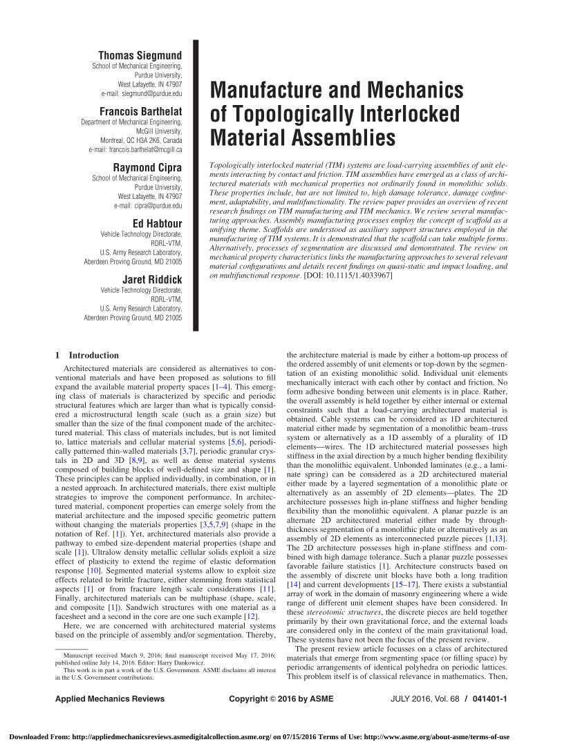
Manufacture and Mechanicsof Topologically InterlockedMaterial AssembliesTopologically interlocked material (TIM) systems are load-carrying assemblies of unit ele-ments interacting by contact and friction. TIM assemblies have emerged as a class of archi-tectured materials with mechanical properties not ordinarily found in monolithic solids.These properties include, but are not limited to, high damage tolerance, damage confine-ment, adaptability, and multifunctionality. The review paper provides an overview of recentresearch findings on TIM manufacturing and TIM mechanics. We review several manufac-turing approaches. Assembly manufacturing processes employ the concept of scaffold as aunifying theme. Scaffolds are understood as auxiliary support structures employed in themanufacturing of TIM systems. It is demonstrated that the scaffold can take multiple forms.Alternatively, processes of segmentation are discussed and demonstrated. The review onmechanical property characteristics links the manufacturing approaches to several relevantmaterial configurations and details recent findings on quasi-static and impact loading, andon multifunctional response. [DOI: 10.1115/1.4033967]
1 Introduction
Architectured materials are considered as alternatives to con-ventional materials and have been proposed as solutions to fillexpand the available material property spaces [1–4]. This emerg-ing class of materials is characterized by specific and periodicstructural features which are larger than what is typically consid-ered a microstructural length scale (such as a grain size) butsmaller than the size of the final component made of the architec-tured material. This class of materials includes, but is not limitedto, lattice materials and cellular material systems [5,6], periodi-cally patterned thin-walled materials [3,7], periodic granular crys-tals in 2D and 3D [8,9], as well as dense material systemscomposed of building blocks of well-defined size and shape [1].These principles can be applied individually, in combination, or ina nested approach. In architectured materials, there exist multiplestrategies to improve the component performance. In architec-tured material, component properties can emerge solely from thematerial architecture and the imposed specific geometric patternwithout changing the materials properties [3,5,7,9] (shape in thenotation of Ref. [1]). Yet, architectured materials also provide apathway to embed size-dependent material properties (shape andscale [1]). Ultralow density metallic cellular solids exploit a sizeeffect of plasticity to extend the regime of elastic deformationresponse [10]. Segmented material systems allow to exploit sizeeffects related to brittle fracture, either stemming from statisticalaspects [1] or from fracture length scale considerations [11].Finally, architectured materials can be multiphase (shape, scale,and composite [1]). Sandwich structures with one material as afacesheet and a second in the core are one such example [12].
Here, we are concerned with architectured material systemsbased on the principle of assembly and/or segmentation. Thereby,
the architecture material is made by either a bottom-up process ofthe ordered assembly of unit elements or top-down by the segmen-tation of an existing monolithic solid. Individual unit elementsmechanically interact with each other by contact and friction. Noform adhesive bonding between unit elements is in place. Rather,the overall assembly is held together by either internal or externalconstraints such that a load-carrying architectured material isobtained. Cable systems can be considered as 1D architecturedmaterial either made by segmentation of a monolithic beam–trusssystem or alternatively as a 1D assembly of a plurality of 1Delements—wires. The 1D architectured material possesses highstiffness in the axial direction by a much higher bending flexibilitythan the monolithic equivalent. Unbonded laminates (e.g., a lami-nate spring) can be considered as a 2D architectured materialeither made by a layered segmentation of a monolithic plate oralternatively as an assembly of 2D elements—plates. The 2Darchitecture possesses high in-plane stiffness and higher bendingflexibility than the monolithic equivalent. A planar puzzle is analternate 2D architectured material either made by through-thickness segmentation of a monolithic plate or alternatively as anassembly of 2D elements as interconnected puzzle pieces [1,13].The 2D architecture possesses high in-plane stiffness and com-bined with high damage tolerance. Such a planar puzzle possessesfavorable failure statistics [1]. Architecture constructs based onthe assembly of discrete unit blocks have both a long tradition[14] and current developments [15–17]. There exists a substantialarray of work in the domain of masonry engineering where a widerange of different unit element shapes have been considered. Inthese stereotomic structures, the discrete pieces are held togetherprimarily by their own gravitational force, and the external loadsare considered only in the context of the main gravitational load.These systems have not been the focus of the present review.
The present review article focusses on a class of architecturedmaterials that emerge from segmenting space (or filling space) byperiodic arrangements of identical polyhedra on periodic lattices.This problem itself is of classical relevance in mathematics. Then,
Manuscript received March 9, 2016; final manuscript received May 17, 2016;published online July 14, 2016. Editor: Harry Dankowicz.
This work is in part a work of the U.S. Government. ASME disclaims all interestin the U.S. Government contributions.
Applied Mechanics Reviews JULY 2016, Vol. 68 / 041401-1Copyright VC 2016 by ASME
Downloaded From: http://appliedmechanicsreviews.asmedigitalcollection.asme.org/ on 07/15/2016 Terms of Use: http://www.asme.org/about-asme/terms-of-use

a load-carrying architectured material is achieved if the geometryof the individual unit element enables topological confinement bythe adjacent unit elements. The resulting architectured materialsare called TIM systems.
Figure 1 depicts one possible configuration of a TIM system.This particular configuration represents a 2D architectured material.The TIM system is obtained by initially considering individual unitelements of polyhedra shape (tetrahedra in the present case). Thesetetrahedra are arranged on a square lattice. Then, adjacent tetrahe-dra have two parallel faces. Since the adjacent tetrahedra are rotated90 deg to each other, the relative rigid body motion is constraint.The particular configuration shown is that of a dense packing of tet-rahedra in a plane [18]. Other geometric configurations for the unitelements and the respective assemblies have been considered. Keyrules for the construction of such architectured materials have beenestablished for 2D regular lattices [19] and were recently extendedto semiregular lattices [20]. With an origin in structural mechanics(Abeille’s dome as reviewed in Ref. [21]), a modern version of atopologically interlocked architectured material was proposed byGlickman [22] in the context of paving system. Subsequently, theinterlocking concept was proposed in the context of engineeringapplications [23], and the term TIM systems was introduced[24,25]. No limitations exist, in theory, on which material class canbe used. TIMs can be made of metallic [26], ceramic [13,27], poly-meric [26,28], unit elements, or even of ice [29]. HeterogeneousTIMs can combine material elements from each class. Finally, thereexist a range of possible approaches on how to provide the con-straint to the TIM system including rigid external or flexible exter-nal system boundaries, internal or external tension cables, as wellas self-supported assemblies [30].
TIM system was found to possess interesting and unusualmechanical properties. A negative elastic stiffness of TIMs wasdocumented [26,31,32] and also reproduced in computer simula-tions. These studies attribute this finding to a change in the contactconditions from face-to-face to face-to-vertex configuration dur-ing loading and the reversal of this process during unloading. Sev-eral investigations demonstrated high damage tolerance for TIMsunder quasi-static loading as cracks are arrested at unit-to-unitcontact surfaces [24]. This feature enables one to construct archi-tectured materials in which brittle solids are transformed intoarchitectured materials with high damage tolerance through thearchitecture of the material [13]. The damage confinement due tocrack arrest at the contact surfaces enables that TIMs can be read-ily remanufactured after complete failure without a significant
loss of properties [33]. In Ref. [11], it was demonstrated that theenhanced damage tolerance inherent to TIMs can be realized alsofor certain ranges of dynamic loading conditions. Recently, Estrinand coworkers [34] demonstrated the control of TIM system stiff-ness through active control of the internal constraint, while Khan-delwal et al. [35] showed the adaptive characteristics of TIMs toenergy absorption based on control of the external constraint. Car-lesso et al. [36,37] illustrated that TIM systems can possessenhanced sound absorption, based on the dynamic contact proc-esses among basic building blocks.
This paper is structures as follows. In Sec. 2, several manufac-turing methods for TIMs are reviewed. Br�echet [38] conceptuallysuggests several manufacturing approaches, but no specific exam-ples are given. The present paper aims to fill this gap and reportsdetails on several relevant approaches for manufacturing of TIMs.These are grouped into bottom-up methods (assembly methodsand 3D printing) and top-down methods (segmentation). The com-monality among all manufacturing approaches discussed here isthe presence of a scaffold. Scaffolds are understood as auxiliarysupport systems enabling the assembly of structures from unit ele-ments. While in the construction of stereotomic structures (archesand domes) and also for TIM-type civil engineering solutionsrigid scaffolds are common, for advanced materials engineeringapplications the concept of the scaffold is re-examined and thescope of the scaffold is expanded. In Sec. 3, experimental evi-dence of mechanical properties and the mechanics of TIMs arereviewed. The paper concludes with a summary and outlook.
2 Methods of Manufacture for TIMs
2.1 Assembly. The discrete nature of TIM systems requiresthe use of some form of scaffold during manufacturing. The useof such scaffolds is common in the construction of arches anddome structures where self-weight is a central feature. For theengineering TIM systems of interest here, the topological inter-locking geometry introduces additional constraints. On the otherhand, there is no need to restrict considerations to the rigid scaf-folds of civil engineering. For manufacturing of TIMs by assem-bly, the starting point is a plurality of (polyhedra) unit elements.Such unit elements can be produced by a range of methods,including conventional computer numerical control (CNC)machining, casting [27], or additive manufacturing [28].
2.1.1 Directional Pick and Place. Pick-and-place assemblyprocesses use machine tools to place individual parts on prede-fined locations. Commonly, the individual parts are moved alongthe direction orthogonal to the assembly plane, and individualparts are not in contact with each other. For TIM systems assem-blies, this basic pick-and-place approach is not possible as theinterlocking geometry of the unit elements and the specific perio-dicity of the assembly (Fig. 1) introduces two additional con-straints. To account for these constraints, a pick-and-place processfor TIMs needs to consider directionality of both the unit elementsin the assembly plane and the positioning approach, and embedboth steps into the assembly sequence.
For TIM assembly, unit elements need not be placed only in theassembly plane, but subsequent directed motion in the assemblyplane is necessary to achieve the topological interlocking geome-try. Furthermore, unit elements need to be positioned in specificorientation. As an example, for the assembly of Fig. 1, tetrahedraare positioned with two edges aligned with the assembly plane.These two edges are orthogonal to each other. Based on these twogeometric features, the assembly approach requires that 0 deg and90 deg oriented tetrahedra, respectively, are moved along one ofthe assembly plane in alternate sequence (Fig. 2). In the assemblyprocess depicted in Fig. 2, gravity provides the directionality forthe assembly. A U-shaped rigid scaffold provides the constraintduring assembly. The frame is made of pieces possessing pris-matic shape such that their cross section engages with the sides ofthe TIM assembly. Tetrahedra are positioned in the drop plane
Fig. 1 Example of a TIM system: (a) a plurality of unit elementsand the principle of topological interlocking. (Reproduced withpermission from Khandelwal et al. [35]. Copyright 2015 by IOPPublishing Limited.) (b) A topologically interlocked architec-tured material.
041401-2 / Vol. 68, JULY 2016 Transactions of the ASME
Downloaded From: http://appliedmechanicsreviews.asmedigitalcollection.asme.org/ on 07/15/2016 Terms of Use: http://www.asme.org/about-asme/terms-of-use
and placed in a sequence of alternating 0 deg and 90 deg. Oncethe desired assembly is completed, the fourth edge of the frame isput in place to constrain the assembly and a complete TIM systemis obtained. This approach has been documented as successful forthe assembly of TIM systems for civil engineering applications,i.e., the construction of a TIM wall for a building structure [40].
Instead of using gravity, a rigid scaffold plane with an inscribedtemplate can be used to provide directionality. Then, the assemblyplane is not constrained to the direction perpendicular to ground.Figure 3 depicts the assembly on such a scaffold. The assemblyprocess of a TIM based on n� n tetrahedra units is enabled by ascaffold consisting of n� n square pyramids which are positionedon a square grid. The edge of each of the square pyramids equalshalf of the tetrahedra edge length. In the embodiment of the pro-cess shown in Fig. 3, a robotic system equipped with a vacuumgripping system was used to pick up unit elements from a source,transport these to the assembly scaffold, and place them withalternating 0 deg and 90 deg orientation. The template providestwo orthogonal assembly motions for the tetrahedra which need tobe moved sequentially in alternating assembly directions corre-sponding to their 0 deg and 90 deg orientation relative to the scaf-fold. There exist TIM configurations, e.g., osteomorphic bricks[41] and truncated tetrahedra, where the support against tipping ofthe unit elements is not required and assembly can be performedon a flat scaffold but the principles of directionality embedded inthe template remain in place for these cases as well. TIM systemsare not restricted to be planar. If the geometry of the unit element
is appropriately distorted, complex TIM shapes can be achieved.In such cases, the scaffold is not restricted to be planar [16].When considering robotic TIM assembly processes, speeds andscales are defined by the capabilities of the robotic devicesemployed, with typical assembly rates of 100–1000 unit elementsper minute. Once the assembly is complete, the TIM system canbe confined externally and be lifted off the template (Fig. 4(a)).Alternatively, the scaffold can become a functional part of theTIM system. In Ref. [12], the authors report on a sandwich panelwith a core made of a TIM system based on osteomorphic brick(Fig. 4(b)). In such a hybrid TIM system, the scaffold thenbecomes one of the facesheets.
2.1.2 Parallel Assembly. Both directional pick-and-placemethods require not only the exact positioning of individual unitelements but also the directed motion of unit elements along spe-cific paths defined for each specific unit element. These limita-tions can be removed if a deformable scaffold is considered, seeFig. 5 for a schematic drawing and Fig. 6 for physical system real-ization. The deformable scaffold is constructed from two sets oforthogonal strings forming an orthogonal template with initialgrid spacing w. The grid is subsequently collapsed into a grid withspacing w0. Unit elements are placed on the scaffold following thetemplate pattern in the open state of the scaffold, and subse-quently, interlocking is achieved simultaneously for all unit ele-ments of the TIM assembly by differential scaling of the scaffoldgrid to its closed state, Figs. 5(b) and 6(c), respectively.
The underpinning concept of the parallel assembly is that arobot would perform a basic pick-and-place operation onto a rec-tangular template in which no interlocking of unit elements is yet
Fig. 2 TIM assembly with gravity assist in a U-shaped rigidscaffold. Individual unit elements are made of a rigid polymerfoam and shaped by a wire cutting process [39]. Unit elementsedge length of a 5 25.0 mm.
Fig. 3 Assembly with rigid scaffold plane and a template. Indi-vidual unit elements made by fused deposition 3D printing, unitelements edge length of a 5 25.0 mm. (Reproduced with permis-sion from Mather et al. [33]. Copyright 2012 by Emerald GroupPublishing Limited.)
Fig. 4 (a) TIM system removed from the scaffold and externally constrained. In thisconfiguration, the external constraint is provided by a prestressed elastic cableguided in tubes. (b) A sandwich panel with a TIM core. In this hybrid TIM system, thescaffold becomes the sandwich facesheet. (Reproduced with permission from Molot-nikov et al. [12]. Copyright 2013 by WILEY-VCH Verlag.)
Applied Mechanics Reviews JULY 2016, Vol. 68 / 041401-3
Downloaded From: http://appliedmechanicsreviews.asmedigitalcollection.asme.org/ on 07/15/2016 Terms of Use: http://www.asme.org/about-asme/terms-of-use

present (Fig. 6(a)). In the open configuration of the scaffold, indi-vidual unit elements are placed without the need for exact posi-tioning (Fig. 6(b)). In the closed state of the scaffold, individualunit elements are then in the position required for the topologicallyinterlocked assembly overall (Fig. 5(c)). The scaffold is embodiedby two orthogonally positioned groups of strings, and a mecha-nism enables that this scaffold of strings only goes through a dif-ferential scaling, with rotation, skew, and translation excluded.
Considering the tetrahedra edge length a, the grid spacing w is atleast sinð45 degÞa but less than a. Experience showed that a valueof w¼ 0.8a is practical. The final grid spacing is w0. Furthermore,the grid must be elevated from ground by distance h for free motionof tetrahedra. Geometry defines h > ðw=2Þtanð54:73 degÞ. Theheight position of the grid is ensured by guiding the strings alongstring guides of at least height h. The selection of the string materialand string tension is dependent on the weight of the tetrahedra con-sidered in the assembly. Tension in individual strings was inducedby the use of springs attached to the string ends. To enable the dif-ferential scaling of the scaffold from grid spacing w to w0, parallelrotating string guides are used, a top and bottom set and a left andright set as in Fig. 7. Two coupler links are used with each set ofstring guides to ensure the parallel rotation between each guide pair(Fig. 6). Each set of string guides is then linked by a coupler (l2) to
a common slider mechanism for actuation of the guides betweenthe open and closed state (Fig. 7). In order to determine the geome-try of the slider, a number of geometric constraints must be deter-mined. Geometric quantities are defined in Fig. 8. The length H isthe distance between the guide pivot and the line of action of theslider. Following Fig. 8, one obtains H¼ l1 cosðaÞþ l2 sinðhcolÞ aswell as H¼ l1 cosðbÞþ l2 sinðhexpÞ. The strike of the slider iss¼ l1 sinðbÞþ l2 cosðhexpÞþ l1 sinðaÞ� l2 cosðhcolÞ. Hereby, l1 is thehalf-length of the string guide link and relates to unit elements inthe assembly n and the string spacing w. In the open state, the twosets of strings are perpendicular, so b¼45deg. To achieve theclosed state with the string spacing w0, the guide rotation angle aþbis required. Once the couple link length l2 is selected, the system ofequations can be solved to obtain the remaining parameters for themechanisms, stroke s and angles hcol, hexp. Considering a linearactuator for the slider, a coupler link length was chosen that corre-sponded to a suitable stroke length for the available linear actuator.
As the assembly process is concluded, the assembly of tetrahe-dra still contains the strings used for the assembly. These stringscan either be seen as sacrificial or be removed once the assemblyis placed in its final constraint. Alternatively, the strings intro-duced by this process can be seen as independent elements whichcan be used to introduce the constraint not through an externalframe but through internal tensile elements. Then, it is of interestto also consider the mechanical properties of the strings. Figure 9depicts two embodiments of TIMs where carbon fiber tow is used
Fig. 5 Deformable (string) scaffold in (a) the open state withgrid spacing w and (b) the closed state with grid spacing w 0,achieved by differential scaling of the scaffold grid [39].
Fig. 6 Mechanism for parallel assembly of a topologically interlocked architectured material with a deformable scaffold: (a)initial placement of unit element on grid, (b) mechanism in open state for the approximate placement of unit elements, and(c) mechanism in closed state. String guides possess pultrusions to guide the strings individually and are free to rotateabout their midspan point [39].
Fig. 7 Mechanism overview for the deformable string scaffold[39].
041401-4 / Vol. 68, JULY 2016 Transactions of the ASME
Downloaded From: http://appliedmechanicsreviews.asmedigitalcollection.asme.org/ on 07/15/2016 Terms of Use: http://www.asme.org/about-asme/terms-of-use
to provide the constraint. The two specimens shown were notdirectly manufactured using the string scaffold, but are used for il-lustrative purpose. For the two TIM configurations in Fig. 9, thesupport elements are not continuous and thus by themselves donot provide in-plane constraint. These components only serve toguide the carbon fiber tow and to apply the out-of-plane displace-ment boundary condition during a loading experiment. There is noprinciple limitation to which materials are considered as strings,and both passive and active materials can be considered.
2.1.3 Self-Assembly. Self-assembly of millimeter-sized par-ticles has been described in the past [42,43] yet without consider-ing topological interlocking geometries. On the millimeter scales,surface tension and other weak interactions are not strong enoughto overcome inertia effects, and stronger interaction forces arerequired. Magnetic forces are ideal for self-assemble at these largelength scales. In addition, mobility needs to be imparted on theunit elements considered for self-assembly. A self-assembly pro-cess enabled by a liquid scaffold is a relevant approach. Here, wereport on a specific self-assembly process where tetrahedra form adense planar packing at a interface between the liquid and air. Inorder to enable the self-assembly process of the tetrahedron, eachunit now contains four small magnets placed at the centroid posi-tion of each tetrahedron facet. Opposing faces are allocated aplus–plus or minus–minus pairing of poles, respectively, to ensurethe directionality of the assembly. Furthermore, the tetrahedrarequire special consideration for their mobility and orientation inthe assembly plane. Floating of tetrahedra is required to be posi-tioned such that one edge is parallel to the bottom of the fluid con-tainer. This orientation of the tetrahedron can either accomplishedthe use of a keel. Classical rules of buoyancy and stability dictatethe density of the fluid and the weight of the keel, once a materialfor the tetrahedra is selected. A typical embodiment of a tetrahe-dron for such self-assembly process is shown in Fig. 10(a). A self-assembled TIM is given in Fig. 10(b). After self-assembly, theTIM system can then be placed in a relevant confinement configu-ration. Magnets can either be left in place or be dissolved. Such a
process can be accomplished with the use of magnets that arebased on magnet particle powder embedded in a polymer region.
2.2 Three-Dimensional Printing. Three-dimensional print-ing approaches allow for the integrated manufacturing of unitcells in the TIM in the final position together with the externalconstraint. computer-aided design (CAD) software and scriptingsoftware are ideal tools to be applied for the creation of the geo-metric models for the TIM assembly and readily lead to theSTereoLithography (STL) files commonly required for 3D printmanufacturing. The assembly template is thus readily encoded. Asacrificial scaffold is inherent to the print process as a supportresin is deposited to enable a multipart 3D print process. Figure11 shows the printer interface with the CAD model for the TIMwith 7� 7 tetrahedra and integrated printed system boundary. Akey parameter in establishing the model is the definition of a gapbetween the unit elements such that the units can be released fromeach other after printing. Such manufacturing-related tolerancesare 3D print system dependent. As one example, experience withthe Connex 350 printer revealed that a gap size of 0.35 mmallowed for the reliable release of unit elements with a¼ 25 mm.Figure 12(a) depicts a final TIM system after removal of the sup-port resin. Metal shim stock along the frame was used to compen-sate for the printing gap and to control the confinement pressurein the assembly. The additive manufacturing process is idealsuited for the manufacture of complex TIM systems, where, e.g.,individual unit elements are heterogeneous. An example of such aTIM assembly is depicted in Fig. 12(b).
2.3 Segmentation. TIM panels can be manufactured as “top-down” in contrast to the bottom-up approach of assembling indi-vidual blocks or to 3D printing. In this strategy, the contours of
Fig. 9 Two TIM systems with internal constraints: (a) a plate-type configuration based on regular tetrahedra [53] and (b) acantilever-type configuration based on truncated tetrahedra.Unit elements are manufactured by fused deposition 3D print-ing; T300 carbon fiber tow is used as the internal constraint.
Fig. 10 (a) Unit element with features for directional self-assembly at the air–fluid interface. Unit element manufacturedby polyjet 3D printing. (b) Self-assembled TIM based on unit ele-ments shown.Fig. 8 Mechanism geometry detail: (a) positions of wire guides
and (b) kinematic relationships [39].
Fig. 11 Three-dimensional printer control software (OBJET
STUDIO) for the manufacture of a TIM system.
Applied Mechanics Reviews JULY 2016, Vol. 68 / 041401-5
Downloaded From: http://appliedmechanicsreviews.asmedigitalcollection.asme.org/ on 07/15/2016 Terms of Use: http://www.asme.org/about-asme/terms-of-use

the blocks are literally carved within a block of monolithic mate-rial [44]. This approach is advantageous because the blocks arecreated in their final position in the panel, and also because it canbe implemented on final products or structures already in place, inorder to augment their mechanical performance. Now, the sur-rounding bulk in its unsegmented states provides the in situ scaf-fold to the TIM system. The approach, however, requires anadequate technology to generate cuts and separate the materialsalong specific surfaces inside the material. The efficacy of thisstrategy was recently demonstrated on borosilicate optical glass,using three-dimensional laser engraving. In this case, the methodsrely on the transparency of glass to laser light in the near UVrange. The three-dimensional laser engraving methods consist infocusing a pulsed laser at a point of predefined location within thevolume of glass. While the unfocused laser does not changethe structure and properties of glass, the energy concentrated atthe focal point is sufficiently high to induce damage, with theprevalent damage mechanism associated to a localized rise oftemperature which generates radial microcracks from thermalhoop stresses (Fig. 13(a)). The pulsed laser beam can be aimedand focused anywhere within the volume of glass, following pre-determined patterns which can be defined using CAD-like pack-age or MATLAB, and which are rapidly created in the material.Arrays of these microcracks form weaker surfaces within the ma-terial, and following the concept of “stamp holes,” these surfacescan guide cracks along specific predetermined directions and con-figurations [13,45]. The toughness of the interfaces generated bylaser engraving can be finely tuned by adjusting the power of thelaser and/or the spacing between the microcracks (Figs.13(b)–13(d)), much like the toughness of a line of stamp holes canbe adjusted by varying the size and spacing of the holes. Figure14(a) show the configuration of three-dimensional interfaceswhich were laser engraved within a 50.8� 50.8 mm, 3.175 mmthick panel of borosilicate optical grade 263M glass. The weakinterfaces define the contours of topologically interlocked blocks,with oblique angle h. The geometry of the individual blocks wasobtained by truncating a tetrahedron which was not necessarilyregular in shape, so that TIM panels with different oblique anglesfor the blocks could be fabricated. These contours were generatednumerically using MATLAB (R2014a, MathWorks, Natick, MA),with each block having dimensions l¼ 6.375 mm andh¼ 3.175 mm (Fig. 14(a)). The three-dimensional model was thenphysically engraved within the borosilicate glass panel using athree-dimensional laser engraver (Model Vitrolux, Vitro LaserSolutions UG, Minden, Germany) equipped with a pulsed UVlaser (355 nm, 0.5 W cw pumped, 4 kHz repetition rate, and 4–5 nspulse duration). The method is highly accurate and producesmaterials with extremely high structural fidelity (Fig. 14(b)).Finally, Fig. 14(c) shows different materials where blocks withoblique angles from h¼ 0 deg to h¼ 20 deg were fabricated. Theengraved panels were attached to a tape and were loaded in bend-ing at different locations to completely separate each block alongthe engraved interfaces.
3 Mechanical Response Characteristics
3.1 Quasi-Static Loading. Figure 15 shows a key observa-tion from investigations of the mechanical response of TIM sys-tems under fixed external confinement subjected quasi-staticloading applied in a transverse direction to the assembly plane.The monolithic equivalent system (a brittle glass plate) fails in abrittle mode with cracks extending throughout the plate; yet, theTIM exhibits a force–deflection response which appears as per-fectly damageable [44]. Instead of a sudden drop in theforce–deflection response for the brittle monolithic system, theTIM force response smoothly increases and decreases responsewith the applied deformation. No major cracks are visible in theTIM specimen. Similar findings are documented in Refs. [31],[33], and [46]. In addition to the monotonic loading case, Estrin
et al. [31] also considered unloading and partial unloading loadpaths and reported the finding of a negative elastic modulus.
In order to further investigate the response of TIMs to mechani-cal loads, several investigators have employed numerical simula-tion tools. In discrete element simulations [32,46,47], theinteraction law between discrete elements is obtained from finiteelement computations considering only two unit elements, andthen, these interaction laws are imparted on the discrete elementmethod (DEM) computation. DEM computations then capture theoverall force–deflection response well.
Finite element simulations are computationally more costlythan simulations with the respective DEM approach but alsoprovide information on the stress and strain fields in the unit ele-ments, as well as enable one to include failure criteria for the unitelements into the simulation [11,26,28,46,48,49]. An example ofsuch simulation and comparison to the experimental findings isshown in Fig. 16, where the deformed TIM configuration (a) iscompared to the finite element method (FEM) prediction of thedeformed TIM shape (b), and the force–deflection data for experi-ments and simulations are compared (c). To obtain such a quanti-tative agreement between simulation and experiment, anappropriate model parameter calibration has to be conducted [11].Under the condition that the elastic modulus of the solid in theunit elements is know, the remaining calibration parameters arethe (linear) contact stiffness and the (Coulomb) coefficient of fric-tion [29]. The results of a parametric study based on finite elementcomputations demonstrate that the coefficient of friction influen-ces the magnitude of the load-carrying capacity as well as thedeflection to final failure. On the other hand, the contact stiffnessaffects only the load-carrying capacity. Consequently, a calibra-tion procedure can be established by which, first, the coefficient offriction is calibrated with respect to the experimental results of thedeflection to final failure, and second, the contact stiffness is tunedto provide the load-carrying capacity in agreement with theexperiments.
Several analytical theories have also been presented to predictthe observed deformation response of TIMs to transverse mechani-cal loads. Estrin and coworkers extend classical beam [23] or plate[50] theories to TIM systems by introducing partial through-thickness cracks. Thereby, the lack of load transfer through part ofthe TIM thickness is accounted for. On the other hand, such anapproach still assumes some tensile stresses in the remaininguncracked ligament. Such tensile stresses would, however, notexist in a TIM where load transfer between unit elements is bycontact only. Brocato and Mondardini [21] used a strain energyapproach to derive the force–deflection response of TIM-like sys-tems. Yet, their approach assumes bending of unit elements as themayor contribution to deformation. Such deformation mode wouldnot be dominant for TIMs as those discussed in the present paperwhere unit elements are restricted to aspect ratios of unity. In Ref.[33], a model based on concepts of post-tensioned masonry wallswas applied to TIMs. Thereby, TIM failure was analyzed and
Fig. 12 (a) A homogeneous 3D-printed TIM. Metal shim stockis used along the frame to control confinement pressure in theassembly. (b) A 3D-printed TIM with microstructured unit ele-ments, unit elements are truncated tetrahedra.
041401-6 / Vol. 68, JULY 2016 Transactions of the ASME
Downloaded From: http://appliedmechanicsreviews.asmedigitalcollection.asme.org/ on 07/15/2016 Terms of Use: http://www.asme.org/about-asme/terms-of-use
predicted as an outcome of unit element strength and the geometryof the material architecture. This model was, however, not appliedto predict the force–deflection response. As an alternative, Khan-delwal et al. [28] proposed a model where load transfer internal toa TIM occurs by compression only and along thrustlines[14,51,52]. For the remainder of this paper, this approach is
referred to as the thrustline deformation (TD) theory of TIMs. Inthe TD theory, the overall nonlinear mechanical response of a TIM(under transverse loading) emerges as a consequence of geometri-cal nonlinearity of the internal thrustline structure.
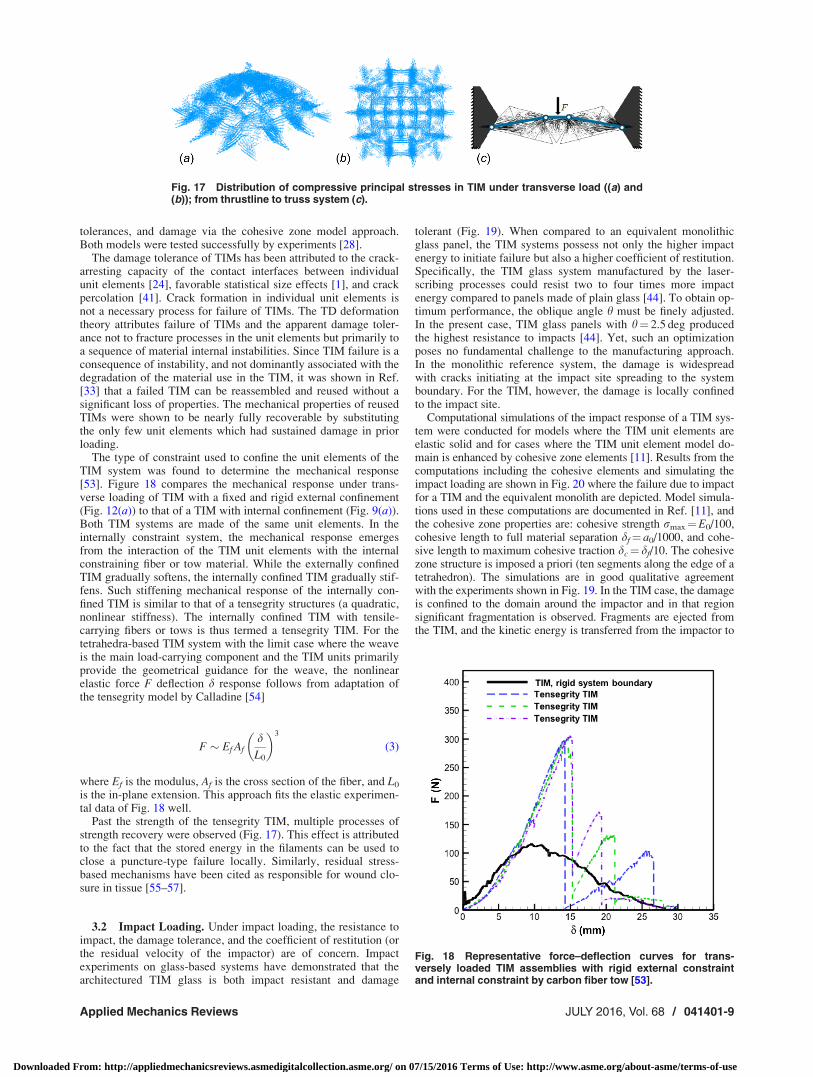
Figures 17(a) and 17(b) depict the computed distribution of themaximum compressive principal stress in a TIM under transverse
Fig. 13 Generating weak interfaces within glass: (a) a nanosecond-pulsed laser focusedbeam creates microdefects at its focal point. Arrays of these defects define the weak interfa-ces between individual blocks. (b) Glass compact tension specimen used to measure thetoughness of the laser-engraved interface; (c) the size of the defects can be adjusted by thepower of the laser; and (d) the toughness of the interfaces can be tuned from zero (“lasercutting”) to the toughness of bulk glass by adjusting the spacing between defects [13,45](original figures by the authors).
Fig. 14 Architectured glass panels: (a) numerical models where the interfaces define andarray of truncated tetrahedra which are topologically interlocked, (b) picture of the laser-engraved panel, and (c) top view of four engraved panels with different oblique angles.(Reproduced with permission from Mirkhalaf et al. [44]. Copyright 2016 by Elsevier.)
Applied Mechanics Reviews JULY 2016, Vol. 68 / 041401-7
Downloaded From: http://appliedmechanicsreviews.asmedigitalcollection.asme.org/ on 07/15/2016 Terms of Use: http://www.asme.org/about-asme/terms-of-use
loading. Figure 17(c) depicts the substitution of the thrustline withthe truss structure. In the TD theory, the force–deformationresponse of a TIM is then computed as the response of the equiva-lent truss structure emerging from the thrustlines. This recognizesthe discrete nature of the TIM and the relevance of thecompression-only load transfer across the unit-to-unit contacts.The load-carrying capacity of the TIM is limited by an internalinstability process inherent in the equivalent truss structure. Indi-vidual thrustlines (i.e., equivalent trusses) sequentially go throughan instability process similar to that occurring in a van Misestruss. Accounted for in its sequential nature, this sequence ofinstability events allows one to understand the failure response asan instability processes. Considering a linear TD theory, eachthrustline carries in-plane fH and out-of-plane fV forces
fH ¼ ga20E
2Rp;0 þ a0ð Þ � 2r þ að Þ2Rp;0= cos nþ a0
fV ¼ fH tan n tan n ¼ h� d
l0 þ fH2Ega0
(1)
where Rp,0, a0 and r, a define the equivalent truss length and unitelement size in the undeformed deformed state, respectively. Theangle n defines the inclination of the thrustline to the plane independence of the displacement di at the center of the thrustlinesystem. In using this formulation for TIM, it is considered that noload transfer can take place in tension. The segmentation angle hwill determine the virtual cross section of the thrustline ga2
0. Thedependence of g on h reflects the type of segmentation. The over-all force F deflection response is then
F ¼XN
i
fHiðdiÞ (2)
indicating that each TIM configuration possesses N thrustlineslocally experiencing an applied displacement di. The local di is
related to the overall applied displacement d assuming a linearkinematic relationship between the externally applied displace-ment d and the displacement applied to each individual thrustlinedi. The elastic response of individual unit elements is linear andrepresented by the elastic modulus E. The segmentation character-istics of the TIM as expressed by the angle h (Fig. 14) are cap-tured by the parameter g which defines an effective unit-to-unitcontact area. The TD model predictions are in good agreementwith the full-field FE models [38]. In computational models, wehave accounted for more details such as friction, assembly
Fig. 15 Quasi-static force–deflection response of transversely loaded TIM assembly andcomparison to a monolithic equivalent: (a) schematic of experiment, (b) failure pattern inplain glass and architectured glass, (c) force–displacement response measured for plainglass and architectured glass, and (d) force–displacement response measured for severaldifferent architectured glass segmentation angles. (Reproduced with permission from Mir-khalaf et al. [44]. Copyright 2016 by Elsevier.)
Fig. 16 (a) TIM in deformed configuration due to transverseloading, (b) predicted deformed configuration and spatial distri-bution of Mises equivalent stress, and (c) measured and pre-dicted force–deflection response. (Reproduced with permissionfrom Feng et al. [11]. Copyright 2015 by Elsevier.)
041401-8 / Vol. 68, JULY 2016 Transactions of the ASME
Downloaded From: http://appliedmechanicsreviews.asmedigitalcollection.asme.org/ on 07/15/2016 Terms of Use: http://www.asme.org/about-asme/terms-of-use
tolerances, and damage via the cohesive zone model approach.Both models were tested successfully by experiments [28].
The damage tolerance of TIMs has been attributed to the crack-arresting capacity of the contact interfaces between individualunit elements [24], favorable statistical size effects [1], and crackpercolation [41]. Crack formation in individual unit elements isnot a necessary process for failure of TIMs. The TD deformationtheory attributes failure of TIMs and the apparent damage toler-ance not to fracture processes in the unit elements but primarily toa sequence of material internal instabilities. Since TIM failure is aconsequence of instability, and not dominantly associated with thedegradation of the material use in the TIM, it was shown in Ref.[33] that a failed TIM can be reassembled and reused without asignificant loss of properties. The mechanical properties of reusedTIMs were shown to be nearly fully recoverable by substitutingthe only few unit elements which had sustained damage in priorloading.
The type of constraint used to confine the unit elements of theTIM system was found to determine the mechanical response[53]. Figure 18 compares the mechanical response under trans-verse loading of TIM with a fixed and rigid external confinement(Fig. 12(a)) to that of a TIM with internal confinement (Fig. 9(a)).Both TIM systems are made of the same unit elements. In theinternally constraint system, the mechanical response emergesfrom the interaction of the TIM unit elements with the internalconstraining fiber or tow material. While the externally confinedTIM gradually softens, the internally confined TIM gradually stif-fens. Such stiffening mechanical response of the internally con-fined TIM is similar to that of a tensegrity structures (a quadratic,nonlinear stiffness). The internally confined TIM with tensile-carrying fibers or tows is thus termed a tensegrity TIM. For thetetrahedra-based TIM system with the limit case where the weaveis the main load-carrying component and the TIM units primarilyprovide the geometrical guidance for the weave, the nonlinearelastic force F deflection d response follows from adaptation ofthe tensegrity model by Calladine [54]
F � Ef AfdL0
� �3
(3)
where Ef is the modulus, Af is the cross section of the fiber, and L0
is the in-plane extension. This approach fits the elastic experimen-tal data of Fig. 18 well.
Past the strength of the tensegrity TIM, multiple processes ofstrength recovery were observed (Fig. 17). This effect is attributedto the fact that the stored energy in the filaments can be used toclose a puncture-type failure locally. Similarly, residual stress-based mechanisms have been cited as responsible for wound clo-sure in tissue [55–57].
3.2 Impact Loading. Under impact loading, the resistance toimpact, the damage tolerance, and the coefficient of restitution (orthe residual velocity of the impactor) are of concern. Impactexperiments on glass-based systems have demonstrated that thearchitectured TIM glass is both impact resistant and damage
tolerant (Fig. 19). When compared to an equivalent monolithicglass panel, the TIM systems possess not only the higher impactenergy to initiate failure but also a higher coefficient of restitution.Specifically, the TIM glass system manufactured by the laser-scribing processes could resist two to four times more impactenergy compared to panels made of plain glass [44]. To obtain op-timum performance, the oblique angle h must be finely adjusted.In the present case, TIM glass panels with h¼ 2.5 deg producedthe highest resistance to impacts [44]. Yet, such an optimizationposes no fundamental challenge to the manufacturing approach.In the monolithic reference system, the damage is widespreadwith cracks initiating at the impact site spreading to the systemboundary. For the TIM, however, the damage is locally confinedto the impact site.
Computational simulations of the impact response of a TIM sys-tem were conducted for models where the TIM unit elements areelastic solid and for cases where the TIM unit element model do-main is enhanced by cohesive zone elements [11]. Results from thecomputations including the cohesive elements and simulating theimpact loading are shown in Fig. 20 where the failure due to impactfor a TIM and the equivalent monolith are depicted. Model simula-tions used in these computations are documented in Ref. [11], andthe cohesive zone properties are: cohesive strength rmax¼E0/100,cohesive length to full material separation df¼ a0/1000, and cohe-sive length to maximum cohesive traction dc¼ df/10. The cohesivezone structure is imposed a priori (ten segments along the edge of atetrahedron). The simulations are in good qualitative agreementwith the experiments shown in Fig. 19. In the TIM case, the damageis confined to the domain around the impactor and in that regionsignificant fragmentation is observed. Fragments are ejected fromthe TIM, and the kinetic energy is transferred from the impactor to
Fig. 17 Distribution of compressive principal stresses in TIM under transverse load ((a) and(b)); from thrustline to truss system (c).
Fig. 18 Representative force–deflection curves for trans-versely loaded TIM assemblies with rigid external constraintand internal constraint by carbon fiber tow [53].
Applied Mechanics Reviews JULY 2016, Vol. 68 / 041401-9
Downloaded From: http://appliedmechanicsreviews.asmedigitalcollection.asme.org/ on 07/15/2016 Terms of Use: http://www.asme.org/about-asme/terms-of-use
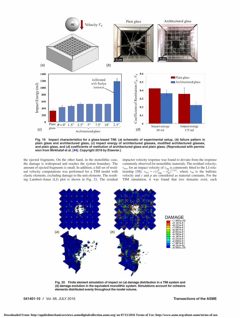
the ejected fragments. On the other hand, in the monolithic case,the damage is widespread and reaches the system boundary. Theamount of ejected fragments is small. In addition, a full set of resid-ual velocity computations was performed for a TIM model withelastic elements, excluding damage to the unit elements. The result-ing Lambert–Jonas (LJ) plot is shown in Fig. 21. The residual
impactor velocity response was found to deviate from the responsecommonly observed for monolithic materials. The residual velocity,vres, for an impact velocity of vim is commonly fitted to the LJ rela-tionship [58]: vres ¼ cðvp
imp � vpblÞð1=pÞ
, where vbl is the ballisticvelocity and c and p are considered as material constants. For theTIM simulation, it was found that two domains exist, each
Fig. 19 Impact characteristics for a glass-based TIM: (a) schematic of experimental setup, (b) failure pattern inplain glass and architectured glass, (c) impact energy of architectured glasses, modified architectured glasses,and plain glass, and (d) coefficients of restitution of architectured glass and plain glass. (Reproduced with permis-sion from Mirkhalaf et al. [44]. Copyright 2016 by Elsevier.)
Fig. 20 Finite element simulation of impact on (a) damage distribution in a TIM system and(b) damage evolution in the equivalent monolithic system. Simulations account for cohesiveelements distributed evenly throughout the model volume.
041401-10 / Vol. 68, JULY 2016 Transactions of the ASME
Downloaded From: http://appliedmechanicsreviews.asmedigitalcollection.asme.org/ on 07/15/2016 Terms of Use: http://www.asme.org/about-asme/terms-of-use
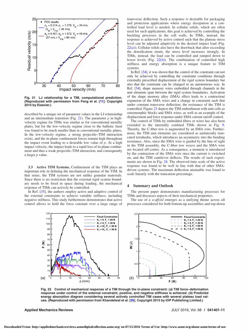
described by a unique set of parameter values in the LJ relationshipand an intermediate transition (Fig. 21). The parameter p in high-velocity regime for TIMs was similar as for conventional metallicplates, but for the low-velocity regime close to the ballistic limitwas found to be much smaller than in conventional metallic plates.In the low-velocity regime, a strong projectile–TIM interactionexists, and the in-plane confinement forces remain high throughoutthe impact event leading to a desirable low value of p. At a highimpact velocity, the impact leads to a rapid loss of in-plane confine-ment and thus a weak projectile–TIM interaction, and consequentlya larger p value.
3.3 Active TIM Systems. Confinement of the TIM plays animportant role in defining the mechanical response of the TIM. Inthat sense, the TIM systems are not unlike granular materials.Since there is no restriction that the external rigid system bound-ary needs to be fixed in space during loading, the mechanicalresponse of TIMs can actively be controlled.
In Ref. [35], the authors employ active and adaptive control ofthe external constraints to achieve variable stiffness, includingnegative stiffness. This study furthermore demonstrates that activecontrol allows to hold the force constant over a large range of
transverse deflection. Such a response is desirable for packagingand protection applications where energy dissipation at a con-trolled load level is needed. In cellular solids, which are oftenused for such applications, this goal is achieved by controlling thebuckling processes in the cell walls. In TIMs, instead, theresponse is achieved by active control such that the plateau stresslevel can be adjusted adaptively to the desired impact load (Fig.22(a)). Cellular solids also have the drawback that after exceedingthe densification strain, the stress level increases strongly. InTIMs, instead, the load can be controlled and ramped down tolower levels (Fig. 22(b)). The combination of controlled highstiffness and energy absorption is a unique feature to TIMsystems.
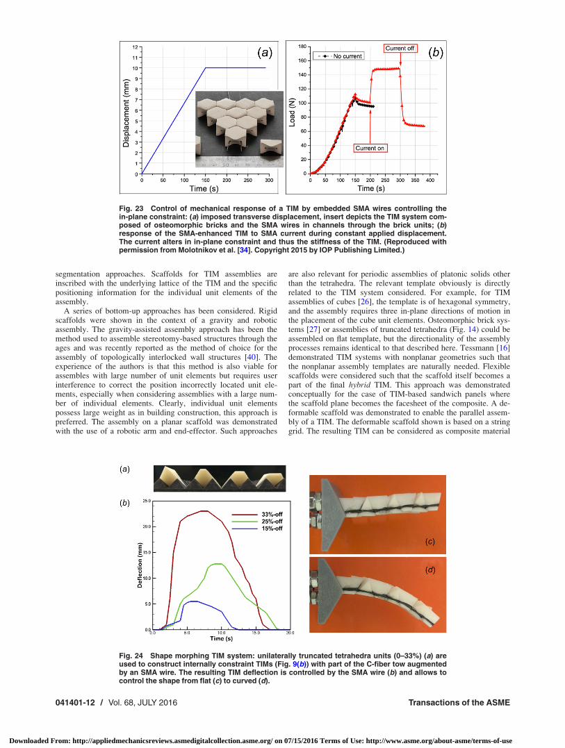
In Ref. [34], it was shown that the control of the constraint can notonly be achieved by controlling the constraint conditions throughexternally prescribed displacement of the rigid system boundary butalso that the constraint can be changed in an autonomous way. InRef. [34], shape memory wires embedded through channels in theunit elements span between the rigid system boundaries. Activationof the shape memory alloy (SMA) effect leads to a contraction/expansion of the SMA wires and a change in constraint such thatunder constant transverse deflection, the resistance of the TIM iscontrolled. Figure 23 depicts the TIM embodiment with unit cells asosteomorphic blocks and SMA wires, as well as an example of thedisplacement and force response under SMA current on/off control.
The control of TIMs by embedded fibers or wires has also beenextended to the internally confined TIMs shown in Fig. 9.Thereby, the C-fiber tow is augmented by an SMA wire. Further-more, the TIM unit elements are considered as unilaterally trun-cated tetrahedra, which introduces an asymmetry into the bendingresistance. Also, since the SMA wire is guided by the line of sightin the TIM assembly, the C-fiber tow weave and the SMA wireare located off-center. As a consequence, a moment is introducedby the contraction of the SMA wire once the current is switchedon, and the TIM cantilever deflects. The results of such experi-ments are shown in Fig. 24. The observed time scale of the activeresponse was found to be well in line with that of other SMA-driven systems. The maximum deflection attainable was found toscale linearly with the truncation percentage.
4 Summary and Outlook
The present paper demonstrates manufacturing processes forTIMs and discusses aspects of their mechanical properties.
The use of a scaffold emerges as a unifying theme across allprocesses considered for both bottom-up assemblies and top-down
Fig. 21 LJ relationship for a TIM, computational prediction.(Reproduced with permission from Feng et al. [11]. Copyright2015 by Elsevier.)
Fig. 22 Control of mechanical response of a TIM through the in-plane constraint: (a) TIM force–deformationresponse under control of the external constraint, positive, and negative stiffness is achieved. (b) Predictedenergy absorption diagram considering several actively controlled TIM cases with several plateau load val-ues. (Reproduced with permission from Khandelwal et al. [35]. Copyright 2015 by IOP Publishing Limited.)
Applied Mechanics Reviews JULY 2016, Vol. 68 / 041401-11
Downloaded From: http://appliedmechanicsreviews.asmedigitalcollection.asme.org/ on 07/15/2016 Terms of Use: http://www.asme.org/about-asme/terms-of-use
segmentation approaches. Scaffolds for TIM assemblies areinscribed with the underlying lattice of the TIM and the specificpositioning information for the individual unit elements of theassembly.
A series of bottom-up approaches has been considered. Rigidscaffolds were shown in the context of a gravity and roboticassembly. The gravity-assisted assembly approach has been themethod used to assemble stereotomy-based structures through theages and was recently reported as the method of choice for theassembly of topologically interlocked wall structures [40]. Theexperience of the authors is that this method is also viable forassembles with large number of unit elements but requires userinterference to correct the position incorrectly located unit ele-ments, especially when considering assemblies with a large num-ber of individual elements. Clearly, individual unit elementspossess large weight as in building construction, this approach ispreferred. The assembly on a planar scaffold was demonstratedwith the use of a robotic arm and end-effector. Such approaches
are also relevant for periodic assemblies of platonic solids otherthan the tetrahedra. The relevant template obviously is directlyrelated to the TIM system considered. For example, for TIMassemblies of cubes [26], the template is of hexagonal symmetry,and the assembly requires three in-plane directions of motion inthe placement of the cube unit elements. Osteomorphic brick sys-tems [27] or assemblies of truncated tetrahedra (Fig. 14) could beassembled on flat template, but the directionality of the assemblyprocesses remains identical to that described here. Tessmann [16]demonstrated TIM systems with nonplanar geometries such thatthe nonplanar assembly templates are naturally needed. Flexiblescaffolds were considered such that the scaffold itself becomes apart of the final hybrid TIM. This approach was demonstratedconceptually for the case of TIM-based sandwich panels wherethe scaffold plane becomes the facesheet of the composite. A de-formable scaffold was demonstrated to enable the parallel assem-bly of a TIM. The deformable scaffold shown is based on a stringgrid. The resulting TIM can be considered as composite material
Fig. 23 Control of mechanical response of a TIM by embedded SMA wires controlling thein-plane constraint: (a) imposed transverse displacement, insert depicts the TIM system com-posed of osteomorphic bricks and the SMA wires in channels through the brick units; (b)response of the SMA-enhanced TIM to SMA current during constant applied displacement.The current alters in in-plane constraint and thus the stiffness of the TIM. (Reproduced withpermission from Molotnikov et al. [34]. Copyright 2015 by IOP Publishing Limited.)
Fig. 24 Shape morphing TIM system: unilaterally truncated tetrahedra units (0–33%) (a) areused to construct internally constraint TIMs (Fig. 9(b)) with part of the C-fiber tow augmentedby an SMA wire. The resulting TIM deflection is controlled by the SMA wire (b) and allows tocontrol the shape from flat (c) to curved (d).
041401-12 / Vol. 68, JULY 2016 Transactions of the ASME
Downloaded From: http://appliedmechanicsreviews.asmedigitalcollection.asme.org/ on 07/15/2016 Terms of Use: http://www.asme.org/about-asme/terms-of-use
system with continuous fibers in a weave embedded in a discon-tinuous matrix. For the self-assembly of tetrahedra into the TIM,structure-specific considerations regarding the orientation and mo-bility of the tetrahedra were required. The liquid-associated buoy-ancy provides the scaffold and mobility at the same time while thepositioning of magnets encodes the assembly template. For osteo-morphic bricks or truncated tetrahedra, the mobility needed forself-assembly processes can be alternatively achieved by the useof low-friction surfaces in combination with vibration, or with air-tables where the air flow per nozzle is altered spatiotemporal.Magnetic elements can be seen as sacrificial, but can also becomeactive elements and for the basis for control of stiffness and damp-ing. Overall, in the experience of the authors, the method of self-assembly is difficult to control, and achieving a well-orderedstructure has proven to be challenging. The 3D printing approachto the manufacturing of TIM system provides a unique opportu-nity to control both geometry and microstructure at the same time.This approach poses no limit to alteration in geometry of the unitelements and of the material in the unit elements. Sacrificial scaf-folds are common to 3D print processes and enable the integratedmanufacture of the TIM with its constraints. The top-down seg-mentation approach documented here is unique in that the scaf-folding is in situ. This enables to locate segmented domains inarbitrary locations in a monolithic material, and to tailor the seg-mentation interfaces in their strength to the specific applicationunder consideration.
TIM systems present an opportunity to expand the availablematerial property space and provide material solutions withenhanced interesting and adaptable deformation characteristics,damage tolerance, dynamic, and acoustical properties. This paperreviews key aspects of quasi-static and impact loading response.The key features that emerge are that load transfer in TIMsemerges as best be described by an approach that explicitlyaccounts for the discrete nature of the microstructure. This is boththe case in numerical simulations with the discrete elementmethod and the finite element method as well as in analyticalapproaches. The mechanical response is then a result of internalinstability processes rather than the stress–strain response of thesolids used to make the unit elements. This finding appears tohold for both TIMs confined externally as well as internally.
TIM systems are reviewed in the context of manufacturingprocesses and related aspects of mechanical properties. While thepresent paper reports on material systems built from unit elementswith size of on the millimeter and centimeter scale, there are noprincipal limitations to consider small- and larger-sized unit ele-ments. Yet, at the same time, specific additional considerationswill be needed in both manufacturing processes and regardingmechanical properties. For example, for micro- and nanometersize unit elements, attractive surface interaction forces betweenunit elements become relevant. Such forces can enhance self-assembly, but would make other assembly processes more diffi-cult. Such attractive surface interactions would also contribute tothe mechanical response of TIMs under external loads by adding atensile component to the particle interaction and thereby leadingto potentially enhanced strength and toughness [23] as well asimpact resistance (Fig. 19). On the other hand, and TIM systemsmade of unit elements of meter size have been considered inbuilding applications. Self-weight of the unit elements then leadsto a selection of manufacturing processes which actively employself-weight [40]. In the mechanical response, self-weight thenexceeds that of external loads [15–17].
TIM system has been proposed as solutions to a range of engi-neering material problems. What readily emerges from the uniquedeformation response to transverse loading is the use of TIMs inprotective layers or coatings [23]. This integration into an engi-neered product has been demonstrated in Ref. [59]. In protectivematerials, lightweighting is often desired and fully dense unit ele-ments in TIMs might not provide an ideal configuration. In Ref.[28], it was demonstrated that the use of cellular unit elements isreadily possible. The desirable energy dissipation characteristics
are not only relevant to quasi-static loading but have (at least froma simulation viewpoint) also been demonstrated for impact loading[11]. The damage tolerance was found to be further enhanced inthe tensegrity-type TIM systems where self-healing type processeshave been documented [53]. Contact interactions bring a range ofnonlinear features into the dynamic response, and such propertieshave been exploited in acoustic applications [36,37]. Architecturedsuch material solutions often enable new multifunctionalities wherematerials are not only selected for their mechanical properties butalso for functional properties [1,38]. Considering the topologicallyengraved glass system described in Refs. [13], [44], and [45], rele-vant applications can be envisioned where optical performance to-gether with toughness and impact resistance is desired, such asglass panels for application in resilient buildings, in safety glass fortransportation applications, light fixtures, or touch screens. At high-temperature, ceramics often provide the only path to achieve ther-mal protection, but ceramics are often far too brittle and lack dam-age tolerance. TIMs have been proposed as alternatives toconventional tile assemblies for such applications [39,60]. Consid-ering aspects of sustainability as a functionality, TIMs—due to thespatial confinement of damage—then provide a path leading to theimplementation of reusable engineering material systems. Respon-sive TIMs [34,35] can form the basis for smart energy absorbingmaterial systems. Based on such approaches, adaptive packagingmaterial can be envisioned, which adaptively can be changed toconform to the present object to be protected. The capability toswitch from high primary stiffness to low secondary stiffness is de-sirable in catching mechanisms where the primary response enablestight position control and the secondary response enables con-trolled energy absorption. The absence or presence of a binder inTIM systems needs to be carefully considered. For some applica-tion scenarios, such as high-temperature applications [39,60],remanufacturing [33], or even extraterrestrial construction [61],binderless systems are desirable. In these cases, TIM has mostlyrelied on frictional interaction between the blocks to generateattractive properties at the macroscale. It is conceivable that themechanics of stress transfer at the interface can be further tailoredand optimized by using a binder [23] such as a polymeric adhesive.The potential of this approach has been recently demonstrated onarchitectured glass panels where the blocks were glued by a ductilepolymer (Surlyn ionomer). The effect was to double the impact re-sistance of the materials (Fig. 12, in Ref. [44]). Hard biologicalmaterials such as seashell, teeth, or bone can, in many ways, beinterpreted as dense architectured materials [62,63]. The mecha-nisms of stress transfer at the many interfaces that these materialscontain are governed by the deformation of thin proteins layerswhich include the formation of ligaments and the unfolding of indi-vidual molecules, or the dynamic breakage and formation of hydro-gen bonds [64]. These highly sophisticated features could serve asinspiration and models for the developed of tailored interfaces insynthetic architectured materials and further expand the potentialapplication domains of the TIM systems reviewed in this article.
Acknowledgment
T.S. acknowledges the funding by the Army Research Office(Grant Mechanics of Multiscale Energy Dissipation in Topologi-cally Interlocked Materials-11.1 STIR), T.S. and R.J.C. acknowl-edge the funding via AFOSR (Grants FQ8671-090162 and FA2386-12-1-3020), as well as the Indiana 21st Century Research and Tech-nology Fund. The work of F.B. was supported by an I2I grant fromthe Natural Sciences and Engineering Research Council of Canadaand by the Fonds de Recherche du Quebec—Nature et Technolo-gies. The contributions by A. Anderson (on self assembly) and Z.Wu (on active systems) are gratefully acknowledged.
References[1] Ashby, M. F., and Br�echet, Y. J. M., 2003, “Designing Hybrid Materials,” Acta
Mater., 51(19), pp. 5801–5821.
Applied Mechanics Reviews JULY 2016, Vol. 68 / 041401-13
Downloaded From: http://appliedmechanicsreviews.asmedigitalcollection.asme.org/ on 07/15/2016 Terms of Use: http://www.asme.org/about-asme/terms-of-use
[2] Ashby, M. F., 2005, “Hybrids to Fill Holes in Material Property Space,” Philos.Mag., 85(26–27), pp. 3235–3257.
[3] Bouaziz, O., Br�echet, Y., and Embury, J. D., 2008, “Heterogeneous and Archi-tectured Materials: A Possible Strategy for Design of Structural Materials,”Adv. Eng. Mater., 10(1–2), pp. 24–36.
[4] Ashby, M. F., 2011, “Hybrid Materials to Expand the Boundaries of Material-Property Space,” J. Am. Ceram. Soc., 94(s1), pp. s3–s14.
[5] Fleck, N. A., Deshpande, V. S., and Ashby, M. F., 2010, “Micro-ArchitecturedMaterials: Past, Present and Future,” Proc. R. Soc. A, 466(2121),pp. 2495–2516.
[6] dell’Isola, F., Steigmann, D., and Della Corte, A., 2015, “Synthesis of FibrousComplex Structures: Designing Microstructure to Deliver Targeted MacroscaleResponse,” ASME Appl. Mech. Rev., 67(6), p. 060804.
[7] Bertoldi, K., Boyce, M. C., Deschanel, S., Prange, S. M., and Mullin, T., 2008,“Mechanics of Deformation-Triggered Pattern Transformations and Superelas-tic Behavior in Periodic Elastomeric Structures,” J. Mech. Phys. Solids, 56(8),pp. 2642–2668.
[8] Nesterenko, V. F., 2001, Dynamics of Heterogeneous Materials, SpringerScience & Business Media, New York.
[9] Porter, M. A., Kevrekidis, P. G., and Daraio, C., 2015, “Granular Crystals: Non-linear Dynamics Meets Materials Engineering,” Phys. Today, 68(11), pp.44–50.
[10] Gu, X. W., and Greer, J. R., 2015, “Ultra-Strong Architected Cu Meso-Lattices,” Extreme Mech. Lett., 2, pp. 7–14.
[11] Feng, Y., Siegmund, T., Habtour, E., and Riddick, J., 2015, “Impact Mechanicsof Topologically Interlocked Material Assemblies,” Int. J. Impact Eng., 75, pp.140–149.
[12] Molotnikov, A., Gerbrand, R., Bouaziz, O., and Estrin, Y., 2013, “SandwichPanels With a Core Segmented Into Topologically Interlocked Elements,” Adv.Eng. Mater., 15(8), pp. 728–731.
[13] Mirkhalaf, M., Dastjerdi, A. K., and Barthelat, F., 2014, “Overcoming the Brit-tleness of Glass Through Bio-Inspiration and Micro-Architecture,” Nat. Com-mun., 5, p. 3166.
[14] Heyman, J., 1966, “The Stone Skeleton,” Int. J. Solids Struct., 2(2), pp.249–279.
[15] Tessmann, O., and Becker, M., 2013, “Extremely Heavy and Incredibly Light:Performative Assemblies in Dynamic Environments,” Open Systems: Proceed-ings of the 18th International Conference on Computer-Aided ArchitecturalDesign Research in Asia (CAADRIA 2013), The Association for Computer-Aided Architectural Design Research in Asia (CAADRIA), Hong Kong, andCenter for Advanced Studies in Architecture (CASA), Department of Architec-ture, National University of Singapore, Singapore, May 15–18, pp. 469–478.
[16] Tessmann, O., 2012, “Topological Interlocking Assemblies,” PhysicalDigitality—Proceedings of the 30th International Conference on Education andResearch in Computer Aided Architectural Design in Europe, Prague, CzechRepublic, Sept. 12–14, Vol. 2, pp. 211–220.
[17] Rippmann, M., and Block, P., 2013, “Rethinking Structural Masonry: Unrein-forced, Stone-Cut Shells,” Proc. Inst. Civ. Eng.: Constr. Mater., 166(6), pp.378–389.
[18] Conway, J. H., and Torquato, S., 2006, “Packing, Tiling, and Covering WithTetrahedra,” Proc. Natl. Acad. Sci., 103(28), pp. 10612–10617.
[19] Kanel-Belov, A. J., Dyskin, A. V., and Estrin, Y., 2010, “Interlocking of Con-vex Polyhedra: Towards a Geometric Theory of Fragmented Solids,” MoscowMath. J., 10(2), pp. 337–342.
[20] Weizmann, M., Amir, O., and Grobman, Y. J., 2015, “Topological Interlockingin Architectural Design,” Emerging Experience in Past, Present and Future ofDigital Architecture—Proceedings of the 20th International Conference of theAssociation for Computer-Aided Architectural Design Research in Asia (CAA-DRIA 2015), Daegu, South Korea, May 20–22, The Association for Computer-Aided Architectural Design Research in Asia (CAADRIA), Hong Kong, pp.107–116.
[21] Brocato, M., and Mondardini, L., 2015, “Parametric Analysis of Struc-tures From Flat Vaults to Reciprocal Grids,” Int. J. Solids Struct., 54,pp. 50–65.
[22] Glickman, M., 1984, “The G-Block System of Vertically Interlocking Paving,”2nd International Conference on Concrete Block Paving, Delft University ofTechnology, Apr. 10–12, American Society for Testing and Materials, Delft,The Netherlands, pp. 345–348.
[23] Dyskin, A. V., Estrin, Y., Kanel-Belov, A. J., and Pasternak, E., 2001, “A NewConcept in Design of Materials and Structures: Assemblies of InterlockedTetrahedron-Shaped Elements,” Scr. Mater., 44(12), pp. 2689–2694.
[24] Dyskin, A. V., Estrin, Y., Kanel-Belov, A. J., and Pasternak, E., 2001,“Toughening by Fragmentation—How Topology Helps,” Adv. Eng. Mater.,3(11), pp. 885–888.
[25] Dyskin, A. V., Estrin, Y., Kanel-Belov, A. J., and Pasternak, E., 2003,“Topological Interlocking of Platonic Solids: A Way to New Materials andStructures,” Philos. Mag. Lett., 83(3), pp. 197–203.
[26] Schaare, S., Dyskin, A. V., Estrin, Y., Arndt, S., Pasternak, E., and Kanel-Belov, A., 2008, “Point Loading of Assemblies of Interlocked Cube-ShapedElements,” Int. J. Eng. Sci., 46(12), pp. 1228–1238.
[27] Krause, T., Molotnikov, A., Carlesso, M., Rente, J., Rezwan, K., Estrin, Y., andKoch, D., 2012, “Mechanical Properties of Topologically Interlocked StructuresWith Elements Produced by Freeze Gelation of Ceramic Slurries,” Adv. Eng.Mater., 14(5), pp. 335–341.
[28] Khandelwal, S., Siegmund, T., Cipra, R. J., and Bolton, J. S., 2012, “TransverseLoading of Cellular Topologically Interlocked Materials,” Int. J. Solids Struct.,49(18), pp. 2394–2403.
[29] Autruffe, A., Pelloux, F., Brugger, C., Duval, P., Br�echet, Y., and Fivel, M.,2007, “Indentation Behaviour of Interlocked Structures Made of Ice: Influenceof the Friction Coefficient,” Adv. Eng. Mater., 9(8), pp. 664–666.
[30] Dyskin, A. V., Pasternak, E., and Estrin, Y., 2012, “Mortarless Structures Basedon Topological Interlocking,” Front. Struc. Civ. Eng., 6(2), pp. 188–197.
[31] Estrin, Y., Dyskin, A. V., Pasternak, E., Schaare, S., Stanchits, S., and Kanel-Belov, A. J., 2004, “Negative Stiffness of a Layer With Topologically Inter-locked Elements,” Scr. Mater., 50(2), pp. 291–294.
[32] Brugger, C., Br�echet, Y., and Fivel, M., 2008, “Experiments and NumericalSimulations of Interlocked Materials,” Adv. Mater. Res., 47–50, pp. 125–128.
[33] Mather, A., Cipra, R. J., and Siegmund, T., 2012, “Structural Integrity DuringRemanufacture of a Topologically Interlocked Material,” Int. J. Struct. Integr.,3(1), pp. 61–78.
[34] Molotnikov, A., Gerbrand, R., Qi, Y., Simon, G. P., and Estrin, Y., 2015,“Design of Responsive Materials Using Topologically Interlocked Elements,”Smart Mater. Struct., 24(2), p. 025034.
[35] Khandelwal, S., Cipra, R. J., Bolton, J. S., and Siegmund, T., 2015, “AdaptiveMechanical Properties of Topologically Interlocking Material Systems,” SmartMater. Struct., 24(4), p. 045037.
[36] Carlesso, M., Molotnikov, A., Krause, T., Tushtev, K., Kroll, S., Rezwan, K.,and Estrin, Y., 2012, “Enhancement of Sound Absorption Properties UsingTopologically Interlocked Elements,” Scr. Mater., 66(7), pp. 483–486.
[37] Carlesso, M., Giacomelli, R., Krause, T., Molotnikov, A., Koch, D., Kroll, S.,Tushtev, K., Estrin, Y., and Rezwan, K., 2013, “Improvement of Sound Absorp-tion and Flexural Compliance of Porous Alumina-Mullite Ceramics by Engi-neering the Microstructure and Segmentation Into Topologically InterlockedBlocks,” J. Eur. Ceram. Soc., 33(13–14), pp. 2549–2558.
[38] Br�echet, Y. J. M., 2013, “Architectured Materials: An Alternative to Micro-structure Control for Structural Materials Design? A Possible Playground forBioinspiration?,” Materials Design Inspired by Nature, Royal Society of Chem-istry, Cambridge, UK, pp. 1–16.
[39] Mather, A., 2007, “Concepts in Improved Product Manufacturability and Reus-ability Through the Use of Topologically Interconnecting Structural Elements,”Master’s thesis, Purdue University, West Lafayette, IN.
[40] Brocato, M., Deleporte, W., Mondardini, L., and Tanguy, J.-E., 2014, “A Pro-posal for a New Type of Prefabricated Stone Wall,” Int. J. Space Struct., 29(2),pp. 97–112.
[41] Molotnikov, A., Estrin, Y., Dyskin, A. V., Pasternak, E., and Kanel-Belov, A.J., 2007, “Percolation Mechanism of Failure of a Planar Assembly of Inter-locked Osteomorphic Elements,” Eng. Fract. Mech., 74(8), pp. 1222–1232.
[42] Golosovsky, M., Saado, Y., and Davidov, D., 1999, “Self-Assembly of FloatingMagnetic Particles Into Ordered Structures: A Promising Route for the Fabrica-tion of Tunable Photonic Band Gap Materials,” Appl. Phys. Lett., 75(26), pp.4168–4170.
[43] Grzybowski, B. A., Stone, H. A., and Whitesides, G. M., 2000, “Dynamic Self-Assembly of Magnetized, Millimetre-Sized Objects Rotating at a Liquid–AirInterface,” Nature, 405(6790), pp. 1033–1036.
[44] Mirkhalaf, M., Tanguay, J., and Barthelat, F., 2016, “Carving 3D ArchitecturesWithin Glass: Exploring New Strategies to Transform the Mechanics and Per-formance of Materials,” Extreme Mech. Lett., 7, pp. 104–113.
[45] Mirkhalaf, M., and Barthelat, F., 2015, “A Laser-Engraved Glass Duplicatingthe Structure, Mechanics and Performance of Natural Nacre,” BioinspirationBiomimetics, 10(2), p. 026005.
[46] Dugue, M., Fivel, M., Br�echet, Y., and Dendievel, R., 2013, “Indentation ofInterlocked Assemblies: 3D Discrete Simulations and Experiments,” Comput.Mater. Sci., 79, pp. 591–598.
[47] Brugger, C., Fivel, M. C., and Br�echet, Y., 2009, “Numerical Simulations ofTopologically Interlocked Materials Coupling DEM Methods and FEM Calcu-lations: Comparison With Indentation Experiments,” Symposium LL—Architectured Multifunctional Materials, MRS Proc., 1188, p. LL05-05.
[48] Khandelwal, S., Siegmund, T., Cipra, R. J., and Bolton, J. S., 2014, “Scaling ofthe Elastic Behavior of Two-Dimensional Topologically Interlocked MaterialsUnder Transverse Loading,” ASME J. Appl. Mech., 81(3), p. 031011.
[49] Brocato, M., and Mondardini, L., 2010, “Geometric Methods and Computa-tional Mechanics for the Design of Stone Domes Based on Abeille’s Bond,”Advances in Architectural Geometry 2010, Springer-Verlag, Vienna, Austria,pp. 149–162.
[50] Khor, H. C., Dyskin, A. V., Estrin, Y., and Pasternak, E., 2004,“Mechanisms of Fracturing in Structures Built From Topologically Inter-locked Blocks,” International Conference on Structural Integrity and Frac-ture, SIF2004, Brisbane, Australia, Sept. 26–29, Australian Fracture Group,Inc., Perth, Australia, pp. 189–194.
[51] Block, P., and Ochsendorf, J., 2007, “Thrust Network Analysis: A New Meth-odology for Three-Dimensional Equilibrium,” J. Int. Assoc. Shell Spat. Struct.,48(3), pp. 167–173.
[52] Block, P., and Lachauer, L., 2014, “Three-Dimensional Funicular Analysis ofMasonry Vaults,” Mech. Res. Commun., 56, pp. 53–60.
[53] Siegmund, T., Khandelwal, S., Wheatley, B., Varanasi, S., Cipra, R., andBolton, S., 2013, “Multifunctional Composites by Segmentation andAssembly,” International Conference on Composite Materials (ICCM-19),Montreal, QC, Canada, July 28–Aug. 2, pp. 23–31.
[54] Calladine, C. R., 1978, “Buckminster Fuller’s ‘Tensegrity’ Structures and ClerkMaxwell’s Rules for the Construction of Stiff Frames,” Int. J. Solids Struct.,14(2), pp. 161–172.
[55] Bowden, L., Byrne, H., Maini, P., and Moulton, D., 2015, “A MorphoelasticModel for Dermal Wound Closure,” Biomech. Model. Mechanobiol., 15(3), pp.663–681.
041401-14 / Vol. 68, JULY 2016 Transactions of the ASME
Downloaded From: http://appliedmechanicsreviews.asmedigitalcollection.asme.org/ on 07/15/2016 Terms of Use: http://www.asme.org/about-asme/terms-of-use

[56] Konrad, W., Flues, F., Schmich, F., Speck, T., and Speck, O., 2013, “An Ana-lytic Model of the Self-Sealing Mechanism of the Succulent Plant DelospermaCooperi,” J. Theor. Biol., 336, pp. 96–109.
[57] Busch, S., Seidel, R., Speck, O., and Speck, T., 2010, “Morphological Aspectsof Self-Repair of Lesions Caused by Internal Growth Stresses in Stems of Aris-tolochia Macrophylla and Aristolochia Ringens,” Proc. R. Soc. London, Ser. B,277(1691), pp. 2113–2120.
[58] Lambert, J., and Jonas, G., 1976, “Towards Standardization in Terminal Ballis-tics Testing: Velocity Representation,” USA Ballistic Research Laboratories,Aberdeen Proving Ground, MD, Technical Report No. 1852.
[59] Wardiningsih, W., Troynikov, O., Molotnikov, A., and Estrin, Y., 2013,“Influence of Protective Pad Integrated Into Sport Compression Garments onTheir Pressure Delivery to Athlete’s Lower Limbs,” Procedia Eng., 60,pp. 170–175.
[60] Estrin, Y., Dyskin, A. V., Pasternak, E., Khor, H. C., and Kanel-Belov, A. J.,2010, “Topological Interlocking of Protective Tiles for the Space Shuttle,”Philos. Mag. Lett., 83(6), pp. 351–355.
[61] Dyskin, A. V., Estrin, Y., Pasternak, E., Khor, H. C., and Kanel-Belov, A. J.,2005, “The Principle of Topological Interlocking in ExtraterrestrialConstruction,” Acta Astronaut., 57(1), pp. 10–21.
[62] Barthelat, F., 2015, “Architectured Materials in Engineering and Biology:Fabrication, Structure, Mechanics and Performance,” Int. Mater. Rev., 60(8),pp. 413–430.
[63] Fratzl, P., Kolednik, O., Fischer, F. D., and Dean, M. N., 2016, “The Mechanicsof Tessellations—Bioinspired Strategies for Fracture Resistance,” Chem. Soc.Rev., 45(2), pp. 252–267.
[64] Barthelat, F., Yin, Z., and Buehler, M. J., 2016, “Structure and Mechanics ofInterfaces in Biological Materials,” Nat. Rev. Mater., 1(4), p. 16007.
Applied Mechanics Reviews JULY 2016, Vol. 68 / 041401-15
Downloaded From: http://appliedmechanicsreviews.asmedigitalcollection.asme.org/ on 07/15/2016 Terms of Use: http://www.asme.org/about-asme/terms-of-use