Embed Size (px)
Citation preview
COMMONWEALTH OF AUSTRALIA
DEPARTMENT OF NATIONAL DEVELOPMENT
BUREAU OF MINERAL RESOURCES GEOLOGY AND GEOPHYSICS
RECORDS:
1967/113
SITE INVESTIGATION TECHNIQUES AT CORIN DA1ffiITE, COTTER RIVER. A.C.T.
by
E.J. Best and J.K. Hill
The information contained in this report has been obtained by the Department of National Development, as part of the policy of the Commonwealth Government, to assist in the exploration and development of mineral resources. It may not be published in any form or used in a company prospectus without the permission in writing of the Director, Bureau of Mineral Resources, Geology and Geophysics.

SITE INVESTIGATION TECHlifIQUES USED AT CORIN DAMSITE COTTER RIVER? A.C.T.
by
* EoJ. Best and J.K. Hill
RECORD '1967/113
~ This paper was presented, by the senior authoJ") to the Fifth Australia - New Zealand ConferencE. on Soil Mechanics and Foundation. Engineering9 which was held in Auckland, New Zealand on 13th to 17th F&bruary, '19670
The information contained in this report has been obtained by the Department of-National Deyelopment ~ as part of the "policy of the Commonwealth Govern.ment v to assist in the exploration and development of mineral. resources o It may not be puhlished in any form or used in a company prospectus without the permission in writing of the Directo!'9 Bureau. of Mineral Resources p Geology and Geophysics o

SITE INVESTIGATION TECHNIQUES USED AT CORIN DAIV[SITE carTER RIVER. AoC.T.
by
E.J. Best and J.K, Hill
RECORD 1967/113
Contents
SYNOPSIS
INTRODUCTION
HISTORY OF INVESTIGATIONS
GENEFcAL GEOLOGY
TECHNIQUES OF nrvEsTIGATION
Diamond Drilling Water Pressure Testing
Field techniq~es Calibration of packers and supply line Correction and presentation of results
Sluicing of Foundations Geophysical Methods
Damsite Spillway Leakage paths from reservoir
ACKNOWLEDGElIlJENTS
REFER'ENCES
TABLES
1. Pressure losses at various flow rates for components
Page
1
2
2
3
4
4 5
5 6 '7 I
11
commonly used in water pressure t;estingo ~3
2. Moduli of elasticity calculated from field meas"C.rements '14 of longitudinal and transverse seismic wave velocities. .
3. Comparison of static and dynamic values of Poisson's Ratio and Young's Modulus obtained from laboratory tests on drill core sampleso 14
FIGURE - Typical geological log of diamond drill hole from Corin Damsite.

, -"
i
. ~
1-1
SI'l'E INVESTIGfJ.'rION TECHNIQUES USED 1\'1' CORIN DAl'IiSI'rE, CQ'l"l.'lill RIVER, A.C.T,
by
-';' • J, Dest':: , J -r TT. 11+ "" ano.. .1\, ill
SYNOPSIS
Corin Dam, which is at present being constructed on the upper reaches of the Cotter River, A.C,T., will be an earth-cored rockf'ill dam, 258 feet high.
Three phases of site investigation - preliminary, feasibility and design - were carried out prior to construction; these are described briefly to show the sequence of investigation, the techniques used, and their relationship to the types of dam considered at each stage of the site investigation.
A brief summary of the geology of the damsite is given.
Although no new methods were used, several of the techniques commonly employed in damsite investigations, such as diamond drilling and water pressure testing, were modified to suit site conditions and to give more meaningful results. Sluicing of selected foundation areas, which is not often used in the investigational stage, was carried out, and played a prominent part in the evaluation of the damsite. Field and laboratory geophysical methods were also used extensively in the preliminary and feasibility investigations. All of these aspects of the Gorin Damsite investigation are described in some detail, as they lJ'k'ly be applicable to investigations of other damsites •
':'lingineering Geologist, Bureau of Mineral Resources, Geology and Geophysics, Canberra, A.C.T.; Australia.
+Lecturer in Engineering Geology, University of Canterbury, Christchurch, New Zealand; formerly with the Bureau of Mineral Resources, Geology and Geophysics.

1-2
INTRODUCTION
Corin Dam will be an earth and rockfill, city water-supply dam, which will contain 1.77 million cubic yards of placed fill. It will be 258 feet high and have a crest length of 926 feet. The storage capacity of the reservoir will be 16,500 million gallons which, together with two slJ1.aller reservoirs downstream, will provide sufficient domestic water for a population of 200,000 in Canberra. The damsite is on the Cotter River, A.C.T., and is 36 miles by road south-west of Canberra.
HISTORY OF INVESTIGATIONS
Corin Damsite, known during the early site investigation as Upper Cotter Damsite E, is one of two alternative sites whioh were investigated during 1961 and 1962. This preliminary investigation consisted of geological mapping of outcrops by plane table tacheometry, supplemented by some pitting and trenching, and was followed by a programme of diamond drilling and water pressure testing* of specifio geological targets. A seismio refraction survey was oarried out at the damsite to supplement information from drilling and surface mapping, and reoonnaissanoe surveys were made of possible souroes of construction materials. It was ooncluded that the site is unsuitable for the oonstruotion of an aroh dam, though it appeared to be well-suited for a concrete gravity or rockfill dam (Best and Hill, 1962).
late in 1963, the decision was nade to construct a dam at Corin Damsite. A detailed feasibility investigation was carried out between January and November 1964 to determine the type of dam most suited to the site. Initially, three types of dam were considered; a conorete buttress dam, a multi-aroh dam, and a rockfill dam. The feasibility investigation, consisting of additional diamond drilling, water pressure testing, geologioal mapping and geophysical investigations, was directed firstly to obtaining general information common to the three types of dam, e.g. distribution of rock types, degree of weathering and jointing, leakage, and so on. Later, special requirements for each type of dam were investigated (such as spillway line for a rockfill dam and buttress foundations for a mUlti-arch dam). A provisional cost-estimate of the three types of dam indicated that the multi-arch and rockfill designs were of oomparable cost, and cpeaper than a buttress dam. At this stage, an earthfill dam was also.considered because test pitting indicated a considerable volume of suitable construction material less than a mile from the damsite; this type of dam was later rejected on economic and technical grounds.
*Water pressure testing oonsists of pumping water, under pressure, into an isolated section of drill hole, and measuring the rates of water loss into the rock at a range of pressures. The authors oonsider that the name of this investigation method is a misnomer, and suggest that "joint permeability testing" would be more accurate. However, to avoid any confusion, the technique will be referred to as "water pressure testing" throughout this paper.
.'
"

\
,.
1-3
One of the major phases of the feasibility investigation was the sluioing of large areas of the proposed foundations with high-pressure water jets. Much valuable geological information was obtained by this teohnique, and three major fault zones were exposed; one of these is oritical, as it affeots a large area of the foundations olose to the dam axis. Insuffioient time was available to determine the exact looation, attitude, and nature of the fault at depth, and this was a major faotor in the deoision of November, 1964 to design and construct a rockfill dam.
The design investigation was initiated as soon as the type of dam had been decided, and continued until July, 1965. By January, 1965, it was deoided that the spillway should be located on the west bank and the diversion tunnel on the east bank. The searoh for construction materials proved more diffioult than anticipated and several possible areas for rockfill were drilled before a suitable quarry site was looated. By July 1965, the spillway site, tunnel portals and valve tower shaft had been investigated by geological mapping, Qiamond drilling and water pressure testing; the main fault zone at the damsite had been interseoted at depth by drilling; an adequate supply of rockfill material had been found; and systematio augering and pitting in the Cotter valley upstream of the damsite had located sufficient impermeable core material (Best, 1965).
The Commonwealth Department of Works directed the site investigation and designed the dam on behalf of the National Capital Development Commission. All ~ological investigations and most of the geophysical traverses were carried out by the Bureau of Mineral Resources, Geology and Geophysics, on behalf of the Commonwealth Department of Works.
GENERAL GEOLOGY
The country rock at the damsite consists of moderately to steeply dipping beds of Lower Palaeozoic quartzite, silicified sandstone, and laminated siltstone» with sandstone predominating over siltstone. The sequence terminates about 1,000 feet west of the river at the Cotter Fault, whioh is a major regional structure; on the western side of the fault older rooks, dominantly phyllite, occur.
The rooks at the damsite are tightly folded with many minor folds on thg limbs of the main antiolines and synclines. The main folds plunge at 20 in a south-easterly direotion. Jointing is prominent in the damsite foundations and an analysis of joint measurements by contoured stereograms showed that they are genetioally related to the compressive forces whioh caused folding; in faot the amount and direction of plunge of the folds was interpreted from the joint stereograms, and later verified during mapping of the sluioed foundation areas. On the west bank, a system of joints parallel to the Cotter Fault is also present. Locally, for example in the noses of folds, the siltstone is oleaved.
Three major faults have been located at the damsite, two of whioh are near-vertioal. In each case the zone of broken rook is narrow and does not unduly affeot the foundations. The third fault dips obliquely upstream at 400 and orops out almost along the line of the dam axis on the lower slopes of the eastern abutment. Clay is extensively developed in this fault zone

1-4
and the hanging-wall rook is closely jointed with many minor seams of clay scattered throughout.
-The zone of weathered bedrock is generally less than 20 feet thick except near faults and in openly-jointed rock. Open jointing occurs in the sandstone and quartzite to considerable depths (up to 150 feet) but joints in the siltstone are generally fresh, clean and tight.
TECHNIQUES OF INVESTIGATION
No new or speoial teohniques were used in the investigation of Corin Damsite. However, several investigation methods were-modified considerably to suit oonditions at the site and geophysioal methods (both field and laboratory) were used extensively. The technique of sluicing, which is not commonly used during the feasibility investigation stage, played a prominent part in the evaluation of thedamsite. Several aspects of the Corin Damsite investigation will now be desoribed, as some features of them may well be applioable to i.nvestigations of other damsites.
DIAMOND DRILLING
Diamond drilling is, generally speaking, the most useful of the site investigation teohniques but it is also the most expensive. It is therefore-important that every effort be made to obtain the maximum value from a drilling programme by oareful·drilling~ optimum oore reoovery and careful handling and preservat-ion- of oore. This should be followed by recording and presenting all the relevant _factual data oonoisely'on drill log sheets.
During the three phases of the Corin Damsite investigation,.a total of 7»170 feet of diamond drilling was oarried out under oontraot by Snowy Mountains Hydro-Electrio Authority drilling teams. All holes we-re drilled using NM1C stationary split inner tube core barrels with. faoe discharge bits and virtually 100 per cent oore recovery was obtained throughout. Face discharge bits prevent drilling water from coming into contact with the core and thereby washing away zones of clay or minutely fractured rock. The split inner tube is particularly useful· in that it allows inspection of the core in a virtually undisturbed state (with whole inner tube core barrels it is often necessary to remove core from the barrel by hammering). Furthermore, the core can be examined before the inevitable disturbance which results when it is transferred to the core box. It has been standard practice throughout the Corin Damsite investigation to photograph each section of core in the split inner tube before removal; this was generally done-by the drillers. The photographic record thus obtained is particularly useful to consultants and tenderers in assessing drill cores and logs.
Careful logging of drill core is very important in site investigation; sophisticated drilling techniques are of little use if the extra information obtainable is not recorded clear~ and ooncisely. Few accounts have been written on methods of presenting drill core logs for engineering purposes and there is ample scope for an interchange of ideas on this subject. Not only is it important that all relevant data should be recorded, but the format of the log should be designed so a.8 to present the data_
I

.'
1-5
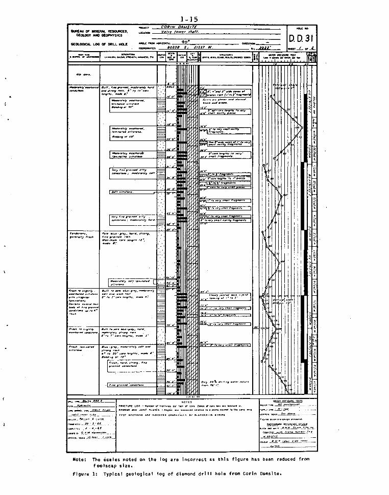
in a convenient manner. An attempt was made during the Corin Damsi te investigation to improve on earlier drill logs and Fig. 1 is a typical example o~ one o~ the later geological log sheets. New features are the fracture log and the method of presentation of water pressure test results. The fracture log, which is a graphic representation of the number o~ fractures per ~oot of core, is sometimes only semi-quantitative in nature but nonetheless it serves to emphasise visually zones of broken and sound rock and variations in joint spaoing. The graphical method of showing water losses has the advantage of showing the actual uncorrected readings ~or each test section. The more usual presentation of histograms ~or a pre-determined range of gauge pressures neoessitates interpolation of field data; this is undesirable because the reliability of the measured data cannot be gauged from the log sheet. It should also be noted that all information necessary for the oorrection o~ ~ield readings is included on the drill log sheet.
WATER PRESSURE TESTING
Water pressure testing of diamond drill holes is generally standard practice in damsite investigations in Australia because it provides valuable in~orn:ation on the openness of jointing in the foundation rocks; it also provides a good qualitative indication of the likely extent of curtain and consolidation grouting.
Recent analysis of the results of grouting at Bendora Dam (which is located on the Cotter River 8 miles doYmstrearn from Corin Damsite) suggests that cement consumption during grouting can be correlated with corrected water pressure test results (Hill, 1964). As Corin Dam is located in a similar geological environment, an attempt is being made to apply the correlations at Corin Dam. It is also proposed that the information obtained from this project be combined with that from Bendora Dam to produce improved correlations which may be useful at other damsites. To this end, considerable efforts were made during the Corin Damsite investigation to obtain reliable water pressure test results and a technique of testing using gravity feed instead of mechanical pumps was developed. In addition, the down-hole equipment was calibrated so that accurate corrections for pressure loss at various flows can be applied to the test results.
Field Techniques
Water pressure testing during the preliminary investigation was carried out using drill circulation reciprocating pumps. However, because of the high rates o~ leakage through open joints, the capacity of the pumps was insufficient to develop back pressures in many of the test sections. The problem was partly overcome, during the feasibility investigation, by using a centrifugal pump with a capacity of 140 gallons per minute (gop.m.). Sufficient water for fully testing high leakage zones was subsequently provided by two 2,500 gallon galvanised iron tanks (one for use at each drill rig) located at the drill sites and continuously supplied from the river by reciprocating pumps. However, difficulty was experienced in moving the tanks intact from one drill site to another and, in addition, the centrifugal pump was sometimes incapable of building up sufficient pressure. It was therefore decided to place the tanks

1-6
permanently above proposed top water level, one on each river bank, at an elevation sufficient to provide any pressure like~ to be required. The tanks were located 440 and 400 feet vertically above the river on the east and west banks respectively and water was pumped to them continuously by means of reciprocating pumps and a 3-inch pipe line. This system of gravity feed proved to be very successful, obviating the need for a centrifugal pump and eliminating fluctuations of the pressure gauge during testing.
The down-hole arrangement of the water pressure testing gear also required modification because of the very high water losses which sometimes occurred. The use of N-size drill rod in the supply line was undesirable because of the high friction losses. Instead, flush jointed EX casing with an internal diameter of 1~ inches was used and a 2-foot length of the casing was modified to take a pressure gauge at the intake end, below the swivel coupling. EX casing was preferred to AX casing because of the likelihood that some drill holes would have to be reduced to B-size to counteract caving - this was necessary in two holes of the preliminary investigation. N-size mechanical packers with 20 feet of perforated drill rod were used in preference to B-size hydraulic packers because the pressure losses through the packer are thereby minimised. Mechanical packers with four rubbers were used so as to reduce the possibility of water leaking past the packer in the hole and to provide a longer leakage path via joints.
Calibration of Packers and Supply Line
High leakage rates from many of the test sections (up to 100 g.p.m. per 20-foot test section) indicated that pressure losses between the gauge and the test sections could be considerable; such pressure losses should be carefully calculated if accurate results are to be obtained. Normal practice is to correct for frictional resistance in the supply line, hydrostatic pressure of water in the supply line and hydrostatic pressure of groundwater. It was obvious, however, that. with the high water losses recorded in some holes there would be a significant loss of pressure as water flowed through the constrictions in the packers and out through the injector holes into the test section. Calibration tests were therefore conducted on N-size mechanical packers and on both N- and B-size hydraulic packers. A suitably modified 20-foot length of three inch pipe was used to simulate the drill hole. Readings of pressure above and below the packers' were taken for flows ranging from 4 to 80 g.p.m. and the pressure losses were plotted against flow for each packer tested. Corrections for given test flows can then be read from the appropriate graph and applied to the field data. Experience shows that each packer has its own friction characteristics; therefore all packers used on a project should be calibrated.
Drill rods were used for the supply line in some test sections where there was a danger of the packer jamming due to caving. Therefore, the Nsize drill rods were also calibrated to obtain friction losses for different rates of flow. The standard graph produced by the United States Bureau of Reclamation could not be used because streamflow drill rod couplings were used by the drillers' at Carin Damsite~
I

\
. '
1-7
Table 1 gives a series of comparative results of pressure loss for various components commonly used in water pressure testing. It can be seen that the pressure loss through N-size packers becomes significant at flows greater than 20 g.p.m. while for B-size packers, corrections should be applied to results where flows greater than 10 g.p.m. are recorded. The table also shows the efficiency of the N-rod streamflow couplings in reducing friction losses and the advantage in using EX or AX flush jointed casing in sections where high water losses are likely.
Correction and Presentation of Results
In work by the Bureau j the field data are corrected as previously described but instead of plotting histograms to illustrate variations in water loss with depth for eaoh hole, the oorreoted data are used to oaloulate Joint permeabilities in feet per year, using a formula derived by Mr Chapple of the Snowy Mountains Authority. This is done for eaoh set of readings at different pressures in every test seotion and. a mean of the values for each seotion is shown graphioally as a joint permeability histogram. The drill hole histograms are then plotted on a seotion through the damsite and are used to define the probable lower limit of grouting. Although the oaloulated joint permeabilities are not always hydraulioally correct (laminar flow in joints is assumed in the oaloulation whereas turbulent flow undoubtedly occurs in high-loss tests), it is considered that this method is more useful for oomparing results from different drill holes and damsites than the more usual method in which histograms are presented showing water loss from eaoh test section for a set range of pressures.
SLUICING OF FOUNDATIONS
The preliminary investigation indicated that the geological structure at the damsite is complex and it was decided to strip part of the foundation area by bulldozers for the feasibility investigation. This was followed by sluicing seleoted areas of the exposed bedrock to permit detailed geological mapping.
Water for sluicing was obtained from a 25,000 gallon storage tank, sited on a hill 620 feet vertioally above the river, and supplied by two submersible electric pumps through a four=inch pipeline. The equipment was installed primarily to provide a water supply for the oonstruction camp. For sluicing, a three-inch pipeline was laid to the damsite from a T-junction at a suitable point in the tank supply line; the water jet was formed by a one-inch fire hose nozzle, swivel-mounted on a tripod. The gravity head from the tank was sufficient for the water jet to dislodge blocks of rook up to 18 inches aoross. It was found necessary to remove~ by bulldozer, the piles of rook that aooumulated as sluicing progressed •
Sluicing of the bulldozed parts of foundations was confined to two strips, eaoh 25 feet wide, one along the dam axis and the other 60 feet downstream from the axis. The geology of the two sluiced areas on the east bank could not be oorrelated so the intervening area was also sluiced; this exposed the 400 fault zone whioh would otherwise have remained undeteoted until cleaning of the foundations immediately before construotion.

i-8
Sluicing has been of great value in the Corin Damsite investigation. About 40,000 square feet of foundations were sluiced and geologically mapped at 10 feet to 1 inch; this greatly facilitated the interpretation of structure and lithology at the site. Sluicing has also provided a representative sample of the foundations for inspection by engineers, consultants, and prospective tenderers, thus providing a sound basis for the evaluation of the foundation treatment considered necessary. The location of the fault zone during the detailed investigation was an important factor in deCiding the type of dam to be constructed. Had the fault not been discovered until construction had commenced, additional investigation and treatment, with consequent costly delays, would have been inevitable.
GEOPHYSICAL METHODS
Geophysical methods of subsurface investigation are widely used nowadays to provide information on the foundations for major engineering structures. All five main geophysical techniques (seismiC, resistivity, magnetic, gravity and borehole logging) have been used successfully in site investigations but the seismic refraction method is the most widelyUsed technique in engineering geophysics.
There are many ways of conducting and computing seismic refraction surveys, depending on the type of information required. For engineering purposes, the tec~~ique used should be capable of:
1. Carrying out comparatively shallow (less than 300 feet) investigations.
2. Reduction by simple computations so that routine survey procedures may be easily adopted.
3. Determining depths to important refracting horizons at regular intervals.
4. Determining the seismic velocities of the refractors in detail at regular intervals.
The field arrangement and calculation method known as the Method of Differences or Reciprocal Method (Heiland, 1946; Hawkins, 1961) best meets these conditions and this is the method generally used by the engineering geophysics group of the Bureau of Mineral Resources. Most of the geophysical work carried out at Corin Damsite was done by the Bureau (Wiebenga, Polak and Kirton, 1962; Polak and Kevi, 1966).
The seismic refraction method was used during the preliminary investigation of the damsite. Three traverses, totalling 2,150 feet, were conducted to estimate the depth to sound bedrock and to obtain quantitative data on the quality of bedrock.
During the feasibility investigation, geophysical methods were used extensively and a total of 13,000 feet of seismic refraction traversing was carried out; this was supplemented by 19200 feet of resistivity traversing and 5,450 feet of magnetic traversing. In addition to these field investigations, the dynamic and static properties of drill core samples from the damsite were determined in the laborator,y.

The various features investigated geophysically are described separately and in some detail below.
Damsite
Ten seismic refraction traverses, totalling 7,600 feet, were conducted at the damsite. Two of these traverses were also surveyed by the constant electrode spacing resistivity method and seven were re-traversed using a vertical component fluxgate magnetometer; no anomalies were located by the magnetic method.
1 • Bedrock Profiles
The measured seismic velocities fell into three groups, corresponding to the following three layers:
Top layer.
2nd layer.
3rd layer.
Soil with a velooity of 1,000 to 1,800 feet per second (rt/sec.) Rock with weathering along joints, which .are commonly open (4,000 to 5,000 ft/seoo) Rock with seismic veloc i ties of 7,000 to 19,000 ft/ sec.
Seismic velocities in bedrock depend upon rock type and degree of jointing. Thickly bedded sandstone and quartzite transmit seismic waves at 15,000 to 19,000 ft/sec. while the velocity in laminated siltstone on the east bank is 11~000 ft/seco Interbedded sandstone and siltstone transmit seismic waves at velocities of 11,000 to 14,000 ft/sec. depending on the proportion of rock with a high elastic modulus.
Velocities in the deeper 3rd layer of less than 10,000 ft/sec. indicate fault or shear zones. Most of the low velocity zones recorded in the 3rd layer correlate with faults mapped at the surface. Extensions of the two n.ear-vertical faults mapped near the dam axis were located by seismic traverses and the position of the Cotter Fault is clearly evident in the seismic profile across the valley. Low velocities were recorded in the 3rd layer near the 400 fault previously described. Because the fault is gently dipping, it does not show up in-the seismic profile as a welldefined zone; however, the low velocities are indicative of the close jointing and weathering. Two distinct depressions are evident in the profile of the 3rd layer in one of the east bank traverses; these coincide respectively with cleaved shale in the core of a tight fold and a narrow shear zone.
Velocity anisotropy is evident in places where two seismic traverses intersect. For example, in one area of siltstcirte the seismic velocity recorded perpendicular to the strike of bedding was 11,000 ft/sec. whereas in a traverse almost parallel to the strike the velocity was 12,600 ft/sec. The lower velocity is presumably caused by bedding plane joints in the rock.
2. Rock Quail ty
Several three component geophones were used on all seismic traverses to record both longitudinal and transverse seismic waves. The velocities
1=10
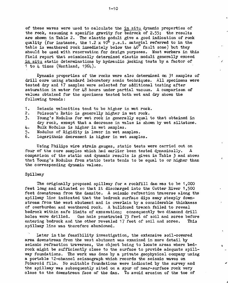
of these waves were used to oalculate the in situ ~namic properties of the rook, assuming a speoifio gravity for bedrock of 2055; the results are shown in Table 2. The elastic ~oduli give a good indication of rook quality (for instance, the 1.2 x iO posoio material referred to in the table is weathered rook immediately below the 400 fault zone) but they should be used with reservation for design purposeso Most workers in this field report that seismioally determined elastic moduli generally exoeed in situ static determinations by hydraulio jacking tests by a factor of 1 to 4 times (Wantland, 1964)0
Dynamic properties of the rooks were also determined on 31 samples of drill oore using standard laboratory sonic techniques 0 All specimens were tested dry and 17 samples were seleoted for additional testing after saturation in water for 48 hours under partial vacuumo A comparison of values obtained for the specimens tested both wet and dry shows the following trends:
1. Seismic velocities tend to be higher in wet rock. 2. Poisson's Ratio is generally higher in wet rock. 3. Young 9 s Modulus for wet rock is generally equal to that obtained in
dry rock, except that a deorease in value is shown by wet siltstone. 4. Bulk Modulus is higher in wet samples. 5. Modulus of Rigidity is lower in wet samples. 6. Logarithmic decrement is higher in wet sampleso
Using Philips wire strain gauges, static tests were carried out on four of the core samples which had earlier been tested dynamically. A comparison of the static and dynamic results is given in Table 3 and shows that Young's Modulus from static tests tends to be equal to or higher than the corresponding ~ami~ values.
Spillway
The originally proposed spillway for a rockfill dam was to be 1,000 feet long and situated so that it discharged into the Cotter River 1,500 feet downstream from the damsite. A seismic refraction traverse along the spillway line indicated that the bedrook surface dips away steeply downstream from the west abutment and is overlain by a considerable thickness of overburden and weathered rock. A bulldozed trench failed to reveal bedrock within safe limits of excavation; consequently two diamond drill holes were drilled. One hole penetrated 73 feet of soil and scree before entering bedrock and the other revealed 17 feet of soil and scree. This spillway line was therefore abandonedo
Later in the feasibility investigation, the extensive soil-covered area downstream from the west abutment was examined in more detail by seismic refraction traverses, the object being to locate areas where bedrock might be sufficiently close to the surface to provide adequate spillway foundations. The work was done by a private geophysical company using a portable 12-channel seismograph which records the seismic wave~ on Polaroid film. No suitable foundations were indicated by the survey and the spillway was subsequently sited on a spur of near-surface rock very close to the downstream face of the dam. To avoid erosion of the toe of

1-11
the dam, the lower end of the spillway chute will be curved in plan and a concrete ski-jump structure will throw the water away from the dam and the tunnel outlet on the opposite bank.
Leakage Paths from the Reservoir
A narrow ridge forms the eastern extension of the east abutment and the distance from the reservoir to the creek on the other side of the ridge is only 2,000 feet. The creek bed is 200 feet vertically below the proposed top water level and although the sediments are virtually impermeable, . leakage could occur along any permeable structures such as faults or joints. To check for possible leakage paths, in addition to detailed geological mapping of the ridge, 3,200 feet of seismic refraction traverses were conducted along the side of the ridge close to top water level. Three low velocity zones in bedrock were located and these were exposed as much as possible by bulldozed trenches. The only major feature which was reveal .. d -, is a shear zone which extends across the ridge and down to the creek on the other side. Where exposed close to top water level, the shear zone intersects siltstone and although the rock is closely jointed, it ~s tight and fresh, and is veined by quartz. The shear zone has subsequently been traced uphill in siltstone and it is considered impossible for extensive water losses to occur through it.
ACKNOWLEDGEMENTS
The authors acknowledge with thanks the permission of the Director of the Bureau of Mineral Resources, Canberra, the Commissioner of the National Capital Development Commission, Canberra, and the Director of the Commonwealth Department of Works, Canberra, to publish material in this paper.
The geological investigations were carried out at all times in close liaison with officers of the Commonwealth Department of Works, and drillers of the Snowy Mountains Hydro-Electric Authority. Their ready assistance and co-operation in developing the techniques described herein is greatly appreciated.
REFERENCES
Best, E.J. 1965: Geological report on the feasibility and design investigation of Corin Damsite, Cotter River, A.C.T., 1964-1965. Bur. Miner. Resources Rec. 1965/200 (unpublished).
Best, E.J., and Hill, J.K. 1962: Geological investigation of Damsite E, Upper Cotter River, A.C.T., 1961. Bur. Miner. Resources Rec. 1962/140 (unpublished).
Hawkins, L.V. 1961: The reciprocal method of routine shailow seismic refraction investigations. Geophysics 26(6):806.
Heiland, C.A. 1946: Geophysical exploration. Prentice Hall, N.Y.:548.

1-12
Hill, J.K. 1964: Foundation grouting and joint permeability measurements at Bendora Dam, A.C.T. Bur. Miner. Resouroes Rec. 1964/140 (unpublished).
Polak, E.J. and Kevi, L. 1966: Cotter Damsite E geophysioal survey, A.C.T., 1964. Bur. Miner. Resources Ree. 1966/30 (unpublished).
Wantland, D. 1964: Geophysical measurements of rook properties in situ. State of Stress in the Earth's Crust, W.R. Judd editor; Elsevier, N.Y.
Wiebenga, W.A., Polak, E.J. and Kirton, M. 1962: Cotter Damsite E seismio refraction survey, A.C.T., 1961. Bur. Miner. Resources Rec. 1962/171 (unpublished).

..
~-13
TABLE 1. PRf:3SURE LOSSES AT VARIOUS FLOW RATES FOR COMPONENTS COMMONLY USED IN WATER PRESSURE TESTING
Pressure loss in p.s.i. at indi oa ted flows g.p .m.
5 10 20 30 40 50 60
100 feet of AX flush-jointed cas ing 0.1 0.3 0.8 1.5 2.8 4.0 5.5
100 feet of EX flush-jointed casing 0.2 0.8 2.8 5.6 10 16 21
100 feet of N -rod with streamflow oouplings 0.4 1.5 5.0 11 18 28 40
100 feet of N -rod with ordinary oottplings 0.8 2.9 11 24 42 65 92
N-mechanical paoker wi th ~ feet perforated N-rod 0.5 1.9 7.5 16 29 45 65
N .. bydraulio packer 0.3 1.3 5.5 13 24 38 56
B-hydraulio packer 2.5 8.5 30 60 101 (150) (205)
Note: Figures in braokets are extrapolated from field results; . all other figures are either interpolated from field results or read from standard graphs of pipe friotion.
"
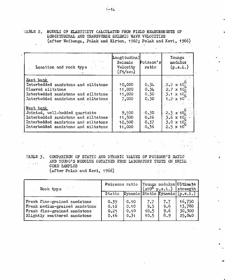
'i.'ABLE 20 MODULI OF ELASTICITY CALCULATED FROM FIELD MEASUR.F1HNTS OF LONGITUDINAL AND TRANSVERSE SEISMIC WAVE VELOCITIES (after Weibengal' Polak and Kirton, 1962; Polak and Kevi, 1966)
Longi tudLl'la" Youngs ' -
Seismic ~oissonts modulus Location and rock ~e Velocity ratio (Pos.i.)
" (ft/se~J , -
East bank 6 Interbedded sandstone and siltstone 10,000 0.34
" 2.2 x10⁶ Cleaved siltstone 11,000 0.34 207x106
Interbedded sandstone and siltstone 11,000 0.30 3.1 x 1°6 Interbedded sandstone and siltstone 7,000 0.30 1~2'x 10 <-
, r
West b§:nk 6 'Jointed, well-bedded quartzite 9,500 -0030 2.3 x 10⁶ ' ,
Interbedded sandstone and siltstone 11,500 o~26 3.6 x 106-" Interbedded sandstone and siltstone 12, ,500 0.37 3.0 x 10⁶ Interbedded sandstone and siltstone 1'1,000 ;0 .. 36 2.5x10
' '
"
: ,
TABLE 3. COMPARIsON OF STATIC AND DYNAMIC VALUES OF POISSON'S RATIOAND YOUNG'S MODULUS OBTAINED FROM LABORATORY TESTS ON .D~ILL CORE S1\MPLES (after, Polak and Kevi 9 1966)
Poissons ratio YoungS mOdt;lus Pltimate Rock type (xlO P.s.~.) strength
Static Dynamio Static ~ic lp.s.i.)
Fresh fine~grained sandstone 0.39 0010 ],,7 7.7 16,750 Fresh medium-grained sand.stone 0.12 0.10 9.5 9,,6 13,780 Fresh fine~grained sandstone 0 .. 21 0.10 10 0 5 9.6- 30,.300 _ SlightlY weathered sandstone 0.16 0.31 '10.,5 8 09 25,040 '
w
1-15 ...... ., CORIN DAMSITE
_AU 11' _RAL R£SOUAC[S. Cl[OI.OGY AlII) GlOPtlYSICS
LOtAn,," _--,V,",.",/:-,Y',-"-=#",, ... -=.,,-,-,.,,~=";..;. _______________ _
0.0.31 OfUn::-=,,::o::;z-:,:-' --
-.. ""'" _ ... __ 9.=0_· _________ _
c:ocRDdIATn 1I02JII $.. SIS37 w. Cl[CILOGICAl. LOG 11' DRILL HOU
No •• ,. •.
~!1''''''''''' •• • "u. ~'_rw'.-..d. ,._.~ ~ •• ~'-. • ... .,~ "Wo, ~"" I.' UY,
1 • ..".44. __ ,:,
I~d.'."" ' .... ,..IIJ I,..,.
~,..,It,.. ",,""'J .H",.".fI "If", ... .''''''rI·~/.'' 1.-,,,,, .... , c ... ' .... , 'o ... ,." No,,. ... ,.,1-.... ". ...... ,_rt" .... ~ 1"" coO
I --·~-" I ..... ,..,... ,11"""0 . • ~.,.,., 4t1-.
P., •• '"', ,,.../. It. I'd, ~""'''g. j,,,. ",. •• ,..d r«1t M"'"tl''' c.,. 1.,..1'#0 1.1", "'0IIf. ,:-
Is' -• NMLC
· . • ', . 10' 0"
4' <II.
. : . III" e'
• :', I' ~
•• '1"'1)' 4'
. ' 'l,.,·,"
· " . Or •
E 100'0'
1:/8IL.~ If'" -., •••• " I NOT[S
.r" ... !~ .... ~,. ... ..-- ..... ,. ..... .,
"",_""_. ,.·s·
0" !:"":';:~/'"Z;;''..,'''~''.1
•• , .. ~~ Ie I" iN"". ,....,. ... ',.
,',A foil "·"''''''J.-III ... ,.., .. "
'0' .",..", .. ,-" ,. .... ,."
.... ~
O,,? SO ,. , .. ,11,,,, ... ~". ","",. ~,..,., .,',:
(fO """,. ... ,,£ ___ ._ ,.-aCTuJl[ LOG-· NUIf\IM. 01 hO(t." .. p •• too. of cor. Z_I.f , .... 10& .... IIIOC ..... ".
~ _l UP( ~~ BEODING &1'110 .rOllin PLAIiI(S ~ A"G'." 0<. "'.u'''',. 'fI.II •• to. 01." ......... , I. '''I 'er. "'. _ N!~!. .. .:.·'.!''..' ~ ..... ! __ .__ _ trST s((rlONS .. lite '''OIC'''[O OJl"PM'C"'~L't' Bf 8lACM[O·'" ATJlU'S
c-.l,l_ '!. .. ,:.!~II.' ~,!c_~.
t.--<o<.'I> __ .!~.:.....J.. ... . ~ - 4. __ '-!
lOOOOofO.'~~~~ __
",."c~ 'UII...!...C!....~!!! ___ 0..~~ __
, I, I
I I·
~'
I;
II ..,,,.,,..1. r
2iJ 't' ~r t
1 I : I i
i I . I .
I
1\
!£.l!'pqf"'ill!~
MC.o,1 f¥"': ~.!!' •• ~'-.
~ . •
"'ltnc.", 9(."l(_..l.!L~ .. ___ _
~"'P" ~~$tlll'!l ..... c • ...:. ..... f ~~_,!._!.:!._ ....... ~~I",! .• ~!_~
_~ ... _"" ".-. _0.' 1.!...l-M'O'~ ____________ _
CQl.OuOt _~~ •. !!...,!'!.'"-.£!!..,:,":'!.I_"---._-.!J!.~. ____________ _
Note: The scales noted on the log are Incorrect as this figure has been reduced from foolscap size.
Figure 1: Typical geological log of diamond drill hole from Corln Oamslte.