Embed Size (px)
Citation preview

BID No XXXXXX
DEPARTMENT OF PUBLIC WORKS
“PROGRESS AS PROMISED”
Contract Documents, Drawings, and Special Provisions For SOUTHERN I-215 BRUCE WOODBURY BELTWAY
LAS VEGAS BOULEVARD TO WINDMILL LANE AND I-215/AIRPORT CONNECTOR INTERCHANGE
FUNDED BY CLARK COUNTY MASTER TRANSPORTATION PLAN FUNDS REGIONAL
TRANSPORTATION COMMISSION OF SOUTHERN NEVADA DENIS CEDERBURG
DIRECTOR CLARK COUNTY PUBLIC WORKS
500 S. GRAND CENTRAL PARKWAY PO BOX 554000
LAS VEGAS, NEVADA 89155-4000
JACOB L. SNOW GENERAL MANAGER
REGIONAL TRANSPORTATION COMMISSION OF SOUTHERN NEVADA
600 S. GRAND CENTRAL PARKWAY LAS VEGAS, NEVADA 89106
COMMISSIONERS Rory Reid, Chairman – Chip Maxfield, Vice-Chair Susan Brager, Tom Collins, Chris Giunchigliani,
Lawrence Weekly, Bruce L Woodbury
Virginia Valentine, County Manager


Southern CC215 Bruce Woodbury Beltway Las Vegas Blvd to Windmill Ln Project No. L-XXXX TOC - 1
SPECIAL PROVISIONS
Southern CC215 – Bruce Woodbury Beltway, Las Vegas Blvd to Windmill Ln
TABLE OF CONTENTS
DIVISION I – GENERAL REQUIREMENTS
Supplement to “Uniform Standard Specifications”
SECTION 100 – GENERAL REQUIREMENTS ..........................................100-1 THROUGH 100-7
SECTION 101 – DEFINITIONS AND TERMS ............................................101-1 THROUGH 101-2
SECTION 102 – BIDDING REQUIREMENTS AND CONDITIONS......................................... 102-1
SECTION 104 – SCOPE OF WORK........................................................................................ 104-1
SECTION 105 – CONTROL OF WORK....................................................105-1 THROUGH 105-25
SECTION 106 – CONTROL OF MATERIALS ............................................106-1 THROUGH 106-5
SECTION 107 – LEGAL REGULATIONS AND RESPONSIBILITIES TO THE PUBLIC ..............................................................107-1 THROUGH 107-7
SECTION 108 – PROSECUTION AND PROGRESS...............................108-1 THROUGH 108-10
SECTION 109 – MEASUREMENT AND PAYMENT ..................................109-1 THROUGH 109-4
SECTION 110 – WAGES AND CONDITIONS OF EMPLOYMENT ............................................................................................. 110-1
SECTION 111 – CONTRACTOR ADMINISTRATION AND QUALITY CONTROL – GENERAL ..................................111-1 THROUGH 111-7
SECTION 112 – ADMINISTRATION OF QUALITY CONTROL ...............112-1 THROUGH 112-15 SECTION 113 – QC ORGANIZATION AND QUALIFICATION OF
INSPECTORS, LABORATORIES AND TECHNICIANS ................................................................113-1 THROUGH 113-11
SECTION 114 – QC INSPECTION PROCEDURES.................................114-1 THROUGH 114-13 SECTION 115 – CONTRACTOR QUALITY CONTROL
ADMINISTRATION AND INSPECTION FORMS...........115-1 THROUGH 115-12 SECTION 116 – CONTRACTOR QUALITY CONTROL TESTING
REPORT SUMMARY FORMS .........................................116-1 THROUGH 116-8
DIVISION II – CONSTRUCTION DETAILS Supplement to “NDOT Standard Details for Road and Bridge
Construction”
Southern CC215 Bruce Woodbury Beltway Las Vegas Blvd to Windmill Ln Project No. L-XXXX TOC - 2
SECTION 200 – ENGINEERING ............................................................................................. 200-1 SECTION 201 – CLEARING AND GRUBBING ....................................................................... 201-1 SECTION 202 – REMOVAL OF STRUCTURES AND
OBSTRUCTIONS.............................................................202-1 THROUGH 202-8
SECTION 203 – EXCAVATION AND EMBANKMENT ...............................203-1 THROUGH 203-4
SECTION 210 – WATERING ......................................................................210-1 THROUGH 210-2
SECTION 211 – EROSION CONTROL ................................................................................... 211-1
SECTION 212 – LANDSCAPING................................................................212-1 THROUGH 212-4
SECTION 213 – IRRIGATION.....................................................................213-1 THROUGH 213-2
SECTION 302 – AGGREGATE BASE COURSES .....................................302-1 THROUGH 302-2
SECTION 401 – PLANTMIX BITUMINOUS PAVEMENTS – GENERAL ..............................................401-1 THROUGH 401-5
SECTION 402 – PLANTMIX BITUMINOUS SURFACE..............................402-1 THROUGH 402-2
SECTION 403 – PLANTMIX BITUMIONS OPEN-GRADED SURFACE ................................. 403-1
SECTION 409 – PORTLAND CEMENT CONCRETE PAVEMENT ...........409-1 THROUGH 409-8
SECTION 411 – ASPHALTIC CONCRETE FRICTION COURSE..............411-1 THROUGH 411-7
SECTION 496 – BRIDGE DECK SEAL CONCRETE .................................496-1 THROUGH 496-7
SECTION 501 – PORTLAND CEMENT CONCRETE ................................501-1 THROUGH 501-5
SECTION 502 – CONCRETE STRUCTURES..........................................502-1 THROUGH 502-11
SECTION 503 – PRECAST PRESTRESSED CONCRETE MEMBERS................................. 503-1
SECTION 505 – REINFORCING STEEL................................................................................. 505-1
SECTION 506 – STEEL STRUCTURES ....................................................506-1 THROUGH 506-5
SECTION 509 – DRILLED SHAFT FOUNDATIONS ..................................509-1 THROUGH 509-2
SECTION 601 – PIPE CULVERTS – GENERAL..................................................................... 601-1
SECTION 603 – REINFORCED CONCRETE PIPE ...................................603-1 THROUGH 603-3
SECTION 605 – PLASTIC PIPE .................................................................605-1 THROUGH 605-2
SECTION 609 – CATCH BASINS, MANHOLES, AND INLETS .................609-1 THROUGH 609-6
SECTION 610 – RIPRAP ........................................................................................................ .610-1

Southern CC215 Bruce Woodbury Beltway Las Vegas Blvd to Windmill Ln Project No. L-XXXX TOC - 3
SECTION 611 – CONCRETE SLOPE PAVING....................................................................... 611-1
SECTION 613 – CONCRETE CURBS, GUTTERS, AND SIDEWALKS.........................................613-1 THROUGH 613-3
SECTION 616 – FENCING ...................................................................................................... 616-1
SECTION 618 – GUARDRAIL.....................................................................618-1 THROUGH 618-3
SECTION 619 – OBJECT MARKERS AND GUIDEPOSTS .......................619-1 THROUGH 619-2
SECTION 623 – SIGNALS, LIGHTING AND INTELLIGENT TRAFFIC SYSTEMS ......................................................623-1 THROUGH 623-10
SECTION 624 – ACCOMODATIONS FOR PUBLIC TRAFFIC ..................624-1 THROUGH 624-6
SECTION 625 – CONSTRUCTION SIGNS ............................................................................. 625-1
SECTION 627 – PERMANENT SIGNS.......................................................627-1 THROUGH 627-3
SECTION 628 – MOBILIZATION ................................................................628-1 THROUGH 628-2
SECTION 632 – PERMANENT PAINTED PAVEMENT MARKINGS.........632-1 THROUGH 632-5
SECTION 633 – PAVEMENT MARKERS................................................................................ 633-1
SECTION 634 – PAVEMENT MARKING FILM........................................................................ 634-1
SECTION 635 – TEMPORARY PAVEMENT STRIPING TAPE .............................................. 635-1
SECTION 636 – TEMPORARY PAINTED PAVEMENT MARKING ........................................ 636-1
SECTION 637 – POLLUTION CONTROL ..................................................637-1 THROUGH 637-6
SECTION 640 – RETAINING WALLS.........................................................640-1 THROUGH 640-4
SECTION 641 – VEHICULAR IMPACT ATTENUATORS ....................................................... 641-1
SECTION 643 – GROUND ANCHORS ....................................................643-1 THROUGH 643-17
SECTION 644 – SOIL NAIL RETAINING WALLS ....................................644-1 THROUGH 644-15
DIVISION III – MATERIALS DETAILS Supplement to “NDOT Standard Details for Road and Bridge Construction”
SECTION 703 – BITUMINOUS MATERIALS .............................................703-1 THROUGH 703-3
SECTION 704 – BASE AGGREGATES................................................................................... 704-1
SECTION 705 – AGGREGATES FOR BITUMINOUS COURSES.............705-1 THROUGH 705-3
SECTION 706 – AGGREGATES FOR PORTLAND CEMENT PRODUCTS .......................... 706-1
SECTION 716 – SIGN MATERIALS ........................................................................................ 716-1
Southern CC215 Bruce Woodbury Beltway Las Vegas Blvd to Windmill Ln Project No. L-XXXX TOC - 4
SECTION 720 – GUARDRAIL MATERIALS ............................................................................ 720-1
SECTION 725 – ELASTOMERIC BEARING PADS................................................................. 725-1
SECTION 730 – TRAFFIC BEADS .......................................................................................... 730-1
SECTION 732 – PAVEMENT MARKING FILM........................................................................ 732-1

SUPPLEMENT TO THE UNIFORM STANDARD SPECIFICATIONS – SECTION 100
DIVISION I – GENERAL REQUIREMENTS
SECTION 100
SPECIAL PROVISIONS
DESCRIPTION
These Special Provisions supplement and modify the "Standard Specifications for Road and Bridge Construction, State of Nevada, Department of Transportation”, 2001 edition, (hereafter referred to as the NDOT Standard Specifications). All of the requirements and provisions of said NDOT Standard Specifications shall apply except where modified by the drawings and these Special Provisions. DIVISION I – GENERAL REQUIREMENTS of these Special Provisions supplement and modify the “Uniform Standard Specifications for Public Works Construction Off-Site Improvements, Clark County Area, Nevada”, third edition, (hereafter referred to as the Uniform Standard Specifications). For clarity, where used in these Special Provisions, the Uniform Standard Specifications and in the NDOT Standard Specifications, the references to State, Department, Contracting Agency, or Engineer shall refer to Clark County. This is an English unit contract and all of the requirements and provisions given therefore shall apply. Make no reference to metric units unless metric units are the only units given or otherwise specified for both English unit and metric unit contracts.
100.01 Location And Scope The work to be performed under this contract is for roadway improvements to the Southern I-215 Bruce Woodbury Beltway from approximately Interstate 15 to Windmill Lane and to the Airport Connector from the Southern I-215 Bruce Woodbury Beltway to the Airport Tunnel. The improvements include median widening of the Southern I-215 Bruce Woodbury Beltway from six (6) to eight (8) lanes from approximately Las Vegas Boulevard South to Windmill Lane and the addition of auxiliary lanes between interchange ramps within the project limits. Existing ramps will be realigned to coordinate with the addition of auxiliary lanes. Additionally, improvements will include three new ramps allowing vehicular access from eastbound I-215, westbound I-215 and George Crocket Road to exit these respective roadways and converge into the center tunnel. The Southern I-215 Bruce Woodbury Beltway/Airport Connector interchange will be modified to include directional ramps for each movement through the interchange. Other associated improvements include five (5) new bridge structures, widening of seven (7) existing bridges, sound walls, and earth retaining structures. Southern CC215 Bruce Woodbury Beltway Las Vegas Blvd to Windmill Ln Project No. L-XXXX
100 - 1

SUPPLEMENT TO THE UNIFORM STANDARD SPECIFICATIONS – SECTION 100
100.02 Reference Specifications And Drawings (a) As provided in paragraph 1 of these Special Provisions, the NDOT Standard
Specifications is hereby incorporated therein by reference. All requirements and provisions of said specifications shall be adhered to in the performance of this contract, except where otherwise provided herein or otherwise shown on the Contract Drawings, and are herein referred to as the "NDOT Standard Specifications."
Likewise, the NDOT Standard Plans for Road and Bridge Construction, latest edition, shall be the standard drawings, and shall be adhered to in the performance of this contract, except where otherwise provided herein otherwise shown on the contract drawings, and are herein referred to as the Standard Drawings. The current revision, as effective at the time of the bid date, shall be used and the Standard Drawings can be verified through the internet at: http://www.nevadadot.com
NOTE: It is the bidder's responsibility to acquire the latest revisions to the "NDOT Standard Specifications" and “NDOT Standard Drawings.”
(b) Copies of the above referenced "NDOT Standard Specifications" and "NDOT Standard Drawings" may be purchased from Nevada Department of Transportation, 1263 South Stewart Street, Carson City, Nevada 89712.
(c) As provided in Section 107.07 of these specifications, all barricading and temporary traffic control signing for the project shall be in accordance with the latest edition of the "Guidelines for Traffic Control in Work Zones" prepared by the Transportation Technology Transfer Center, University of Nevada, Reno (http://www.t2.unr.edu) and "Traffic Control Plans for Highway Work Zones" drawing numbers 601 through 626 (pgs. 140-165) as included in the Standard Drawings.
(d) All work shown on the Contract Drawings which refer to the State of Nevada Standard Plans shall be constructed in accordance with the Nevada Department of Transportation, “2007 Standard Plans for Road and Bridge Construction”, http://www.nevadadot.com .
(e) The "Manual on Uniform Traffic Control Devices" (M.U.T.C.D.), latest edition, is also an integral part of this contract and is hereby incorporated therein by reference. Copies are available for reference at the Office of the Engineer, or may be obtained from the U.S. Government Printing Office, Washington, D.C., 20402.
(f) All work on water distribution facilities shall be in accordance with the “Uniform Southern CC215 Bruce Woodbury Beltway Las Vegas Blvd to Windmill Ln Project No. L-XXXX
100 - 2

SUPPLEMENT TO THE UNIFORM STANDARD SPECIFICATIONS – SECTION 100
Design and Construction Standards for Water Distribution Systems,” latest edition, as published by the Las Vegas Valley Water District. These standards are an integral part of this contract and hereby incorporated therein by reference.
(g) Work on any public utilities shall be performed in accordance with the Standard
Specifications except where modified by the utilities' own standards.
(h) The "Design and Construction Standards for Wastewater Collection Systems,” latest edition, published by the Clark County Water Reclamation District (702) 434-6600, http://www.cleanwaterteam.com, is an integral part of this contract and hereby incorporated therein by reference.
(i) Materials approved by Clark County Public Works, Construction Management Division, 500 South Grand Central Parkway, P. O. Box 554000, Las Vegas, Nevada 89155-4000 are listed on the Clark County Public Works web page http://www.accessclarkcounty.com/pubworks/iquc/QA.htm.
100.03 Contractor's Utilities In accordance with Section 210 of the "Standard Specifications for Road and Bridge Construction, State of Nevada, Department of Transportation," the Contractor shall furnish all water and facilities necessary for the construction under the contract at his own expense. The Contractor shall provide his own telephone, electric power, and any other utility service fees or charges required in performance of the work under the contract and shall pay all installation charges and monthly bills in connection therewith. 100.04 Project Signs Three project signs shall be provided by the Contractor for placement near the limits of the project. The Contractor shall erect said signs at locations as approved by the Engineer. The signs shall be erected at such time as construction activity is visible to the public. The Contractor shall properly maintain said signs throughout the construction until final completion of the contract, or as directed by the Engineer, refer to the end of this section for sign detail. Information regarding prevailing wage rates shall be added to the reverse side of every project sign in minimum three inch (3") lettering. The required verbiage shall be as shown below. ______________________________________________________________________ THIS IS A PREVAILING WAGE PROJECT The hourly labor rates for this project are determined by the State of Nevada. Information on the rates can be obtained by calling the Office of the Labor Commissioner at (702) 486-2650. Southern CC215 Bruce Woodbury Beltway Las Vegas Blvd to Windmill Ln Project No. L-XXXX
100 - 3

SUPPLEMENT TO THE UNIFORM STANDARD SPECIFICATIONS – SECTION 100
Reference PWP# ____________. ESTE ES UN PROJECTO DE SALARIOS DETERMINADOS El salario laboral correspondiente por hora es determinado por El Estado de Nevada. Información acerca de los salarios puede ser obtenida llamando a la Comisión Laboral al (702) 486-2650. Numero PWP de referencia __________ . ______________________________________________________________________ The Contractor's cost for furnishing, installing and maintaining these signs shall be included in the lump sum bid item for traffic control and will not be measured or paid for separately. 100.05 Geotechnical Report A Geotechnical report for this project was prepared by Terracon, entitled “Geotechnical Engineering Report Interstate Route 215/State Route 171 Airport Connector Interchange, Clark County, Nevada, Project No. 64065013, May 29, 2007” and is on file in the Office of the Project Engineer at the Clark County Public Works Department (CCPW), 500 South Grand Central Parkway, Suite 2001, Las Vegas, Nevada, 89155 where it may be examined by prospective bidders. Copies of the Geotechnical Report can be purchased for $20.00 from Terracon. When purchasing the report, please allow a minimum of 24 hours to allow sufficient time for printing. The Geotechnical report prepared for this Contract and other record of subsurface investigations and tests are referenced only for the inspection by bidders. It is understood and agreed that such subsurface information, whether included in the plans, special provisions, or otherwise made available to the bidder, was obtained and is intended for the owner’s design and estimating purposes only. Bidder expressly waives any right to rely on such information for any purpose. Such information has been made available only for the convenience of the bidders. Bidders shall make their own interpretations of the data contained in said report, and the Contractor shall not be relieved of liability under the contract for any loss sustained as a result of any variance between conditions indicated by, or deduced from, said report and the actual conditions encountered during the progress of work. Payment for additional work and materials required to remove unsuitable materials beyond the limits of excavation of sub-grade material encountered during the progress of work will be in accordance with Subsection 109.03, "Extra and Force Account Work." 100.06 Lump Sum Bid Breakdown
Southern CC215 Bruce Woodbury Beltway Las Vegas Blvd to Windmill Ln Project No. L-XXXX
100 - 4

SUPPLEMENT TO THE UNIFORM STANDARD SPECIFICATIONS – SECTION 100
The purpose of the bid breakdown shall be to provide a basis for partial payment and/or analysis by the Engineer before awarding the contract. Any and all of the bidders may be required to prepare an itemized bid breakdown, on a form to be provided, at any time after the opening of bids as requested by the Engineer. This form is intended to include all major items, and the lump sum bid computed therefore will be the maximum compensation for all work and materials whatsoever furnished by the Contractor in order to comply with the Contract Drawings and Specifications in their present form, whether or not indicated in the approximate quantities or pertaining to the items or work listed therein. 100.07 Partnering The Owner desires to encourage the foundation of a cohesive partnership with the Contractor and its subcontractors. This partnership will be structured to draw on the strengths of each organization to identify and achieve reciprocal goals. The objectives are effective and efficient contract performance, intended to achieve completion within budget, on schedule, and in accordance with plans and specifications. This partnership will be multilateral in makeup, and participation will be totally voluntary. To implement this partnership initiative, it is anticipated that prior to the Notice to Proceed the Contractor's and the Owner's key personnel will attend a partnership development seminar and team-building workshop. Follow-up workshops may be held periodically throughout the duration of the contract as agreed to by the Contractor and the Owner.
An integral aspect of partnering is the resolution of disputes in a timely, professional, and non-adversarial manner. Alternative dispute resolution (ADR) methodologies will be encouraged in place of the more formal dispute resolution procedures. ADR will assist in promoting and maintaining an amicable working relationship to preserve the partnership. ADR in this context is intended to be a voluntary, non-binding procedure available for use by the parties to this contract to resolve any dispute that may arise during performance. In this vein, the Owner, likewise, expresses a preference that unresolved disputes be submitted to mediation prior to going into arbitration. Any costs associated with effectuating this partnership will be agreed to in advance by both parties and will be shared equally with no change in contract price. 100.08 NPDES Permit As of January 31, 2005 NDEP will only accept the new Notice of Intent (NOI) “Section 6 – Certification” for an application of coverage under the Stormwater permit for Construction activities. Access to the NEW APPLICATION (Stormwater NOI) can be obtained through their web site at: http://www.ndep.nv.gov/bwpc/constructionnoi/signin.aspx Nevada Division of Environmental Protection, Bureau of Water Pollution Control, has issued general permit NVR10000 that covers construction activities within the state of
Southern CC215 Bruce Woodbury Beltway Las Vegas Blvd to Windmill Ln Project No. L-XXXX
100 - 5

SUPPLEMENT TO THE UNIFORM STANDARD SPECIFICATIONS – SECTION 100
Nevada. In order to be covered by the permit, Contractor shall submit, at no extra cost to Owner, a Notice of Intent (NOI) with a Stormwater Pollution Prevention Plan (SPPP) and the required filing fee to the attention of Clifford Lawson (775-687-9429) at: Nevada Division of Environmental Protection, Bureau of Water Pollution Control, Capital Complex, 333 West Nye Lane, Carson City, Nevada 89706. Further information and copies of the required (NOI) may be obtained on the Internet at http://www.ndep.nv.gov/bwpc/storm_cont03.htm. 100.10 Utility Relocations Contractor shall identify and coordinate the relocation of existing utility lines, removal of existing overhead and underground services, and construction of new services as required to be completed in order to meet the schedule for this Contract. Contractor shall incorporate into Contractor’s schedule, mutually agreed upon time frames for utility construction by other contractors to ensure that appropriate windows of opportunity are available for utility relocations without hampering or delaying Contractor’s own operation. Contractor shall provide each utility company with mutually agreed upon notification time, sufficient to construct new or relocate existing facilities and avoid construction conflict. The following list identifies the utility companies and their respective facilities that have been located within or in close proximity to this project: Southwest Gas Corporation – Jim Dufault, Government Liaison, 365-2097 Nevada Power Company – Neal Dostick, Distribution, 657-4990 Embarq Telephone Company – Steve Smith, Engineer, 244-7290 Las Vegas Valley Water District – Steve Jackson, Engineering Services, 258-3249 Clark County Water Reclamation District – Christine Dudas, P.E., 450-4486 FAST – Jesus Marmolejo, 229-6611 Cox Communications – Dan Defiesta, 384-8084 x8276
Southern CC215 Bruce Woodbury Beltway Las Vegas Blvd to Windmill Ln Project No. L-XXXX
100 - 6

SUPPLEMENT TO THE UNIFORM STANDARD SPECIFICATIONS – SECTION 100
PROJECT SIGN – NOT TO SCALE
Southern CC215 Bruce Woodbury Beltway Las Vegas Blvd to Windmill Ln Project No. L-XXXX
100 - 7

SUPPLEMENT TO THE UNIFORM STANDARD SPECIFICATIONS - SECTION 101
SECTION 101
DEFINITIONS AND TERMS
This subsection is changed to read as follows: 101.28 Holidays In the State of Nevada, holidays occur on:
January 1 (New Year’s Day) Third Monday in January (Martin Luther King Jr.’s Birthday) Third Monday in February (President’s Day) Last Monday in May (Memorial Day) July 4 (Independence Day) First Monday in September (Labor Day) Last Friday in October (Nevada Day) November 11 (Veterans’ Day) Fourth Thursday in November (Thanksgiving Day) Friday following fourth Thursday in November (Family Day) December 25 (Christmas Day)
Or on any day that may be appointed by the President of the United States for public fast, thanksgiving or as a legal holiday. If January 1, July 4, November 11, or December 25 falls upon a Sunday, the Monday following shall be observed as a holiday. If January 1, July 4, November 11, or December 25 falls upon a Saturday, the Friday preceding shall be observed as a holiday. The following subsection is added:
101.76 Notice to Contractors All or any portion of a utility, including sewer laterals, conduit, wire, cable or duct, including meters, between a utility distribution line and an individual customer or customers. The following subsections are added: 101.77 Nominal Diameter Nominal diameter shall be defined as the inside diameter of a standard pipe as specified by the manufacturer. Southern CC215 Bruce Woodbury Beltway Las Vegas Blvd to Windmill Ln Project No. L-XXXX 101 - 1

SUPPLEMENT TO THE UNIFORM STANDARD SPECIFICATIONS - SECTION 101
101.78 De-Watering De-watering shall be defined as removal and/or lowering of any surface or sub-surface water by a method chosen by the Contractor and acceptable to the Engineer, which results in a ground moisture content which enables construction to be carried out under relatively dry and stable conditions. Unless specifically indicated elsewhere in these specifications, no separate payment will be made for de-watering but shall be included in other items of work.
Southern CC215 Bruce Woodbury Beltway Las Vegas Blvd to Windmill Ln Project No. L-XXXX 101 - 2

SUPPLEMENT TO THE UNIFORM STANDARD SPECIFICATIONS - SECTION 102
SECTION 102
BIDDING REQUIREMENTS AND CONDITIONS
The following subsection is added: 102.14 Escrowing of Bid Documents As allowed by recent changes to NRS 338.140(2), the County desires to have the Contractor escrow bid documents electronically. The three (3) apparent low bidders, including their sub-contractors to the 1 % level, will be required to submit all quantity take-offs, crew, equipment, rates of production, material costs and all other information used in the calculation of the contractor’s bid. This information shall be transmitted electronically via the Internet following the Bidlocker protocol that can be found at www.bidlocker.com. The three apparent low bidders shall complete the archiving of this data not later than four (4) hours after the posted bid opening time. Failure to do so by any bidder will cause that bidder to be considered unresponsive. It is understood that this data remains the property of the contractor(s) and will not be divulged without the consent of the contractor. The Bidlocker file of the successful bidder who is awarded the contract will only be accessed if, in the opinion of the Engineer, it is deemed necessary for any of the specific reasons stated in NRS 338.140(1)(d). The contractor shall only open the file with the Engineer present. The appropriate information shall be extracted from the archived file and printed or otherwise copied for future reference if necessary. The Bidlocker file of the two (2) unsuccessful bidders will be deleted upon award of the contract to the successful bidder. Any bidders desiring to request an “or-equal” substitution for the Bidlocker system must do so in writing not later than one week prior to bid opening. The successful bidder will pay the fee for use of the Bidlocker system by all three bidders from the item “Bidlocker Fee Allowance”. For bidding purposes, the “Bidlocker Fee Allowance” is $5,000.00 and entered on the bid schedule.
Southern CC215 Bruce Woodbury Beltway Las Vegas Blvd to Windmill Ln Project No. L-XXXX 102 - 1

SUPPLEMENT TO THE UNIFORM STANDARD SPECIFICATIONS - SECTION 104
SECTION 104
SCOPE OF WORK
104.01 Maintenance of Traffic The first paragraph of this subsection is changed to read as follows: The number of lanes on Warm Springs Road and Paradise Road shall not be reduced during the hours of 6:00 am and 9:00 pm. One lane in each direction may be taken at other times with the written approval of the OWNER. Unless otherwise noted in the contract plans, these Special Provisions, or at the direction of the OWNER, the Contractor shall construct the required improvements in such a manner and sequence that not less than two 12-foot wide paved travel lanes (one in each direction) remain open to traffic at all times along all other area roadways. Travel lanes shall only be closed while active work in or adjacent to the travel lane being closed is occurring. During the working hours approved by the OWNER, a two-lane two-way roadway may be reduced to one lane using one-lane one-way traffic control methods per the MUTCD and/or the NDOT Standards Plans for Road and Bridge Construction as approved by the OWNER. Turn lanes shall be a minimum of ten feet wide and shall remain available for use continuously during the peak traffic hours at all intersection on all roadways where they currently exist or as deemed necessary by the OWNER. The length of turn pockets may be reduced from what currently exists with written permission of the OWNER. The OWNER reserves the right to adjust the times, number of lanes, and length of turn pockets at any time due to significant congestion, significant citizen’s complaints, or safety considerations. Do not allow public traffic or pedestrians in the area directly beneath the construction of falsework, directly beneath steel girders during erection, directly beneath bridge spans while they are being lowered in to place, and all other operations that could pose a safety hazard to the public. All existing public roads and haul routes are to remain open until the detours and/or alternate routes are completed to the satisfaction of the owner.
Southern CC215 Bruce Woodbury Beltway Las Vegas Blvd to Windmill Ln Project No. L-XXXX 104 - 1

SUPPLEMENT TO THE UNIFORM STANDARD SPECIFICATIONS - SECTION 105
SECTION 105
CONTROL OF WORK 105.02 Plans And Working Drawings The following is added to this subsection: Contract Drawings applicable to the work to be performed under the contract have the title and drawing number as follows:
I-215 Bruce Woodbury Beltway Las Vegas Boulevard to Windmill Lane
Drawings No. L-XXXX 105.05 Cooperation By Contractor The first paragraph is changed to read as follows: The Owner will furnish to the Contractor, without charge, 10 sets of Special Provisions together with 10 sets of Drawings. One set each of which the Contractor shall keep available on the work site at all times. Additional quantities of Special Provisions and Drawings will be furnished to the Contractor at the cost of reproduction upon request to the contracting agency. The third paragraph is changed to add the following: Prior to issuance of Notice to Proceed, the Contractor shall submit to the Engineer in writing the names of at least three (3) 24-hour emergency contract personnel who have personal knowledge of the work and can respond to emergency situations. At least one of those persons listed must be available locally at all times during the contract period. This submittal shall include, at a minimum, home, office, fax, and cellular telephone numbers for these personnel. 105.06 Cooperation With Utilities The following is added to this section: The Owner and Engineer do not guarantee that all existing utilities are shown on the contract drawings, or that the utilities are shown in their exact locations. Furthermore, the Owner has not indicated utility service connection laterals on the Contract Drawings. During all time periods when any utility valve, manhole, vault, or pull box may be buried or otherwise rendered inaccessible, the Contractor shall have personnel and equipment on standby (respond within 1 hour) to uncover any valve, manhole, vault or pull box when requested by the Engineer or owning agency.
Southern CC215 Bruce Woodbury Beltway Las Vegas Blvd to Windmill Ln Project No. L-XXXX 105 - 1

SUPPLEMENT TO THE UNIFORM STANDARD SPECIFICATIONS - SECTION 105
All utility valves, manholes, vaults, or pullboxes which are buried shall be conspicuously marked in a fashion acceptable to the owner and Engineer by the Contractor to allow their location to be determined by the Engineer or utility personnel under adverse conditions, (inclement weather or darkness). All cost for providing standby personnel and equipment and for uncovering buried facilities shall not be paid for separately but shall be considered incidental to the items of work associated with the burial except for service connections, which may affect the work. The Contractor shall pothole to determine the exact vertical and horizontal location of all existing utilities indicated on the Drawings, or marked in the field, crossing or in close proximity to the proposed reinforced concrete box and channel, pipelines, mains, and laterals and pier locations at least (10) days in advance of the construction of the facilities and no later than fifteen (15) working days following Notice to Proceed. No separate payment will be made for potholing. It will be considered incidental to Contract bid items. Contractor shall provide Engineer all pothole information obtained including measurements, dimensions, elevations, types and sizes of utilities within one working day following the potholing. From this information, Engineer will determine additional utility conflicts which may not be shown on the Drawings. If any utility conflicts exist that are not shown on the Drawings, Contractor will take the necessary action in accordance with this subsection and Subsection 105.09 Construction Interferences. During the performance of contract work, the owner of any utility affected by the work shall have the right to enter, when necessary, upon any portion of the work for the purpose of maintaining service and of making changes in, or repairs to, said utility. When the plans or specifications provide for the Contractor to alter, relocate, or reconstruct a utility, the bid prices shall include the cost of any temporary bypasses that may be required by the affected utility. It is the Contractor's responsibility under Section 102.05 to satisfy himself prior to bidding as to the requirements of each utility and utility modification. The relocation of utility service connections will be paid for in accordance with subsection 105.09, "Construction Interferences" of these special provisions. The Contractor shall not be assessed liquidated damages for failure to complete the work on time to the extent that such delay was caused by failure of the owner or agency having jurisdiction over the utility or service connection to authorize or otherwise provide for its removal, relocation, protection, support, repair, maintenance, or replacement. The Contractor shall not shut off the water supply to a hydrant, nor in any way, prevent access to a fire hydrant until he has secured permission to do so from the proper
Southern CC215 Bruce Woodbury Beltway Las Vegas Blvd to Windmill Ln Project No. L-XXXX 105 - 2

SUPPLEMENT TO THE UNIFORM STANDARD SPECIFICATIONS - SECTION 105
authorities. 105.08 Construction Stakes, Lines And Grades The third paragraph of this subsection is deleted and the following substituted in place thereof: The Contractor shall preserve property line and corner survey monuments except where their destruction is determined by the Engineer to be unavoidable. Monuments that are disturbed or destroyed by the Contractor's operations will be replaced in accordance with all applicable Nevada Revised Statutes and Standard Drawings by a Nevada Professional Land Surveyor and the cost for such replacement will be deducted from any money due, or which may become due, the Contractor under this contract. CHECK WITH SURVEY DIVISION FOR STAKING REQUIREMENTS The Contractor shall allow a minimum of two (2) working days notice when submitting survey work requests. If multiple requests are submitted, prioritization of said requests will be provide by the Contractor with consideration given to the length of time required to complete each ordered task. The following construction stakes will be furnished by the Owner: 1. Stakes at 50-foot intervals along the back of all curb and gutter and at the ends
and center of each curb return, or at offsets that may be requested by the Contractor.
2. Stakes at 50-foor intervals for construction of drainage and utility pipes along an offset line chosen by the Contractor.
3. Two (2) stakes, containing horizontal and vertical control of each manhole, and drop inlets.
4. Stakes at the corners of junction structures containing horizontal and vertical control.
5. One (1) stake for each street light pole and two (2) stakes for traffic signal containing horizontal and vertical control.
6. Subgrade stakes will be placed at 100-foot intervals (plus grade breaks) and three (3) across the asphaltic pavement area (maximum). Type II stakes will be placed at a maximum three (3) stakes per 50-foot stations plus grade breaks.
The Contractor shall notify the Engineer prior to placement of curb and gutters at drop inlets to verify the form work elevations.
Southern CC215 Bruce Woodbury Beltway Las Vegas Blvd to Windmill Ln Project No. L-XXXX 105 - 3

SUPPLEMENT TO THE UNIFORM STANDARD SPECIFICATIONS - SECTION 105
The above construction stakes shall constitute the field control by and in accordance with which the Contractor shall execute the work, and will be furnished at no expense to the Contractor. The Engineer will set stakes in addition to these delineated above, if required by and requested by the Contractor; however, costs for setting said additional stakes shall be paid by the Contractor and will be deducted from any amounts due or to become due the Contractor. After stakes and marks have been set it shall be the responsibility of the Contractor and his employees to protect the stakes and marks against vandalism and/or destruction. Should any of the stakes or marks be destroyed or disturbed by the Contractor's operations or otherwise, the cost of replacing said stakes or marks shall be paid by the Contractor and will be deducted from any amounts due or to become due the Contractor. The following subsection shall be added: 105.09 Construction Interferences Construction interferences shall consist of any utility or service connection that is required to be disturbed, modified, relocated, or removed to permit the construction of a pipeline or other structure as specified in the contract. Such disturbance or removal shall be done only with the approval of the project Engineer and following notification to the owner of the interfering utility or service connection. Any such utility or service connection removed or otherwise disturbed shall be reconstructed as promptly as possible in its original or other authorized location in a condition at least as good as prior to such removal or disturbance, subject to the inspection of the owner of same. The Contractor's responsibility under this subsection to remove or replace shall apply even in the event such damage or destruction occurs after backfilling or is not discovered until after completion of backfilling. The owner of the utility or service connection shall be notified immediately after damage or destruction occurs or is discovered. A Class 1 construction interference shall be defined as to include any utility or service connection within the limits of excavation or over-excavation, required by the Contract Drawings or as ordered by the Engineer, that is not located within the pipe space. A Class 2 construction interference shall be defined as to include any utility or service connection located within the pipe space. Pipe space shall be defined as to be the outside diameter or dimension of the pipeline or structure, plus 6-inches. All costs involved in removing, relocating, protecting, supporting, repairing, maintaining, or replacing a utility or service connection shall be borne by the Contractor per the following descriptions and as shown on the chart at the end of this section:
Southern CC215 Bruce Woodbury Beltway Las Vegas Blvd to Windmill Ln Project No. L-XXXX 105 - 4
SUPPLEMENT TO THE UNIFORM STANDARD SPECIFICATIONS - SECTION 105
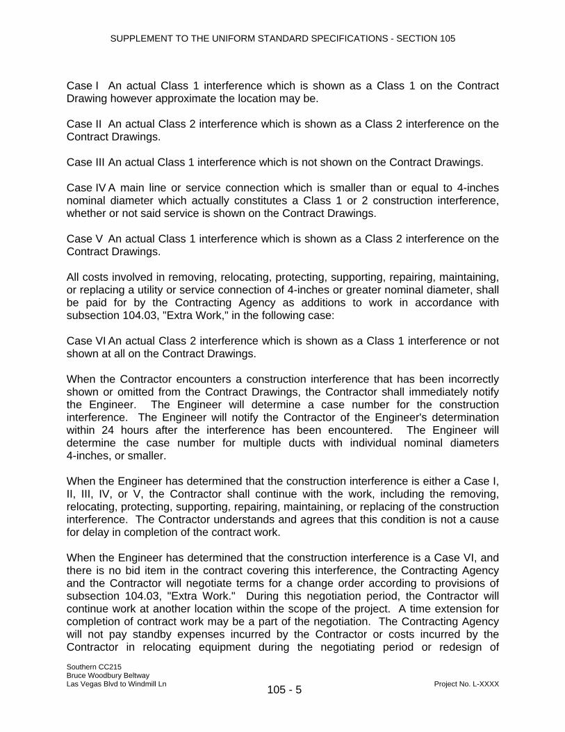
Case I An actual Class 1 interference which is shown as a Class 1 on the Contract Drawing however approximate the location may be. Case II An actual Class 2 interference which is shown as a Class 2 interference on the Contract Drawings. Case III An actual Class 1 interference which is not shown on the Contract Drawings. Case IV A main line or service connection which is smaller than or equal to 4-inches nominal diameter which actually constitutes a Class 1 or 2 construction interference, whether or not said service is shown on the Contract Drawings. Case V An actual Class 1 interference which is shown as a Class 2 interference on the Contract Drawings. All costs involved in removing, relocating, protecting, supporting, repairing, maintaining, or replacing a utility or service connection of 4-inches or greater nominal diameter, shall be paid for by the Contracting Agency as additions to work in accordance with subsection 104.03, "Extra Work," in the following case: Case VI An actual Class 2 interference which is shown as a Class 1 interference or not shown at all on the Contract Drawings. When the Contractor encounters a construction interference that has been incorrectly shown or omitted from the Contract Drawings, the Contractor shall immediately notify the Engineer. The Engineer will determine a case number for the construction interference. The Engineer will notify the Contractor of the Engineer's determination within 24 hours after the interference has been encountered. The Engineer will determine the case number for multiple ducts with individual nominal diameters 4-inches, or smaller. When the Engineer has determined that the construction interference is either a Case I, II, III, IV, or V, the Contractor shall continue with the work, including the removing, relocating, protecting, supporting, repairing, maintaining, or replacing of the construction interference. The Contractor understands and agrees that this condition is not a cause for delay in completion of the contract work. When the Engineer has determined that the construction interference is a Case VI, and there is no bid item in the contract covering this interference, the Contracting Agency and the Contractor will negotiate terms for a change order according to provisions of subsection 104.03, "Extra Work." During this negotiation period, the Contractor will continue work at another location within the scope of the project. A time extension for completion of contract work may be a part of the negotiation. The Contracting Agency will not pay standby expenses incurred by the Contractor or costs incurred by the Contractor in relocating equipment during the negotiating period or redesign of
Southern CC215 Bruce Woodbury Beltway Las Vegas Blvd to Windmill Ln Project No. L-XXXX 105 - 5

SUPPLEMENT TO THE UNIFORM STANDARD SPECIFICATIONS - SECTION 105
proposed improvements due to construction interferences. The Contractor shall exercise extreme care so as not to damage new or existing buried utilities which do not physically constitute a construction interference and shall utilize equipment throughout his construction operations so that new and existing utilities are not damaged. The Contractor shall be responsible for costs of removing, relocating, protecting, supporting, repairing, maintaining, or replacing new or existing facilities damaged by his operations as determined by the Engineer. 105.14 Maintenance During Construction The following is added to this subsection: The Contractor shall maintain a temporary AC patch over backfilled pipe trenches, subject to traffic, during the course of the project to the satisfaction of the Engineer. The temporary patch shall be permanently repaired or removed as soon as the Contractor's operations allow. Temporary asphalt patching will not be allowed to remain longer than 30 calendar days before permanent paving is placed. Should areas of temporary pavement fail and become hazardous, the Contractor shall repair at the Engineer's direction and at the Contractor's expense. Temporary asphaltic pavement shall be placed in accordance with subsection 208.03.05, "Cutting and Restoring Street Surfacing" per Clark County Special Provisions. 105.16 Final Acceptance This subsection is changed to read as follows: Upon due notice from the Contractor of presumptive completion of the entire project and the submittal of Record Drawings, the Engineer will make an inspection. If all construction, final clean up, and Record Drawings provided for and contemplated by the contract are found completed to his satisfaction, the inspection shall constitute the final inspection and the Engineer will so advise the governing body or commission. The Contractor will then be notified in writing of the acceptance of the contract as of the date of the final inspection. Such notice will not be given to the board or commission until all work, including Record Drawings as required by GC. 6.2 of the General Conditions (check if correct section of contract documents), has been completed to the satisfaction of the Engineer. 105.17 Claim for Adjustment And Disputes The following is added after the first paragraph of this subsection: Southern CC215 Bruce Woodbury Beltway Las Vegas Blvd to Windmill Ln Project No. L-XXXX 105 - 6

SUPPLEMENT TO THE UNIFORM STANDARD SPECIFICATIONS - SECTION 105
For all claims, the Contractor shall certify in writing that the claim is made in good faith, that the supporting data are accurate and complete to the best of the Contractor’s knowledge and belief, and that the amount requested accurately reflects the Contract adjustment for which the Contractor believes the Owner is liable. Subcontractor claims shall not be considered except as submitted and certified by the Contractor as the Contractor’s claim. Subcontractor claims shall not be considered except as submitted and certified by the Contractor as the Contractor’s claim. The following subsections are added. 105.18 Authorized Changes All changes to the plans performed in the field shall be reviewed, approved and authorized by the Engineer prior to proceeding with the work. Any changes to the plans without authorization may result in removal of such item at the Contractor's expense or non-payment for the work, at the discretion of the Engineer. Verbal authorized changes to the plans in the field will not be considered for additional quantities or compensation, but can be and will be considered for any reduction in quantities or cost. Any authorized changes to the plans which are approved by the Engineer for additional compensation shall be in written form indicating all items of work involved and the cost for each item, and will be submitted to the Engineer prior to proceeding with the work involved. Any authorized changes for the convenience of the Contractor will not be considered for additional quantities or payment, unless the Engineer has approved such additional cost in writing to the Contractor. (Coordinate with revisions to QC program.) 105.19 Contractor Quality Control Program Quality control, to insure that materials and workmanship incorporated into the work meet the requirements of the Standard Specifications, Special Provisions, and all other contract documents is the sole responsibility of the Contractor. Quality Control shall be performed in accordance with Version 1.02 of Clark County Public Work’ s “Quality Systems Manual Series 1 - Quality Control Program Manual for Contractor, Source, and Production Organizations”. Quality Control Program shall include all quality testing required by both the NDOT Standard Specification for Road and Bridge Construction and these Special Provisions. No additional payment shall be made for required quality control testing not listed on the Clark County Public Works Frequency tables. The “Quality Systems Manual Version 1.02" can be acquired from Clark County Southern CC215 Bruce Woodbury Beltway Las Vegas Blvd to Windmill Ln Project No. L-XXXX 105 - 7

SUPPLEMENT TO THE UNIFORM STANDARD SPECIFICATIONS - SECTION 105
Public Works as specified in 100.02 (i). 105.19.01 Revision To Quality System Manual The following revisions shall be made to Version 1.02 of Clark County Public Work’s “Quality Systems Manual - Quality Control Program Manual for Contractor, Source, and Production Organizations”: Introduction SECTION 1.02, page 1-2, last paragraph add: The technician certification shall comply with the Nevada Alliance for Quality Transportation Construction (NAQTC), which includes ACI components for concrete sampling. For Laboratory concrete testing, the technician shall be certified as ACI Laboratory I or ACI compressive strength concrete cylinders. CCPW approved NAQTC apprentices may be utilized with a maximum of two technicians for laboratory and/or field per contract. Contact Clark County Public Works Construction Division for the current NAQTC apprentice program procedures. SECTION 3.01 - Control of Work - General The following shall be added to this section: All Quality Control measures are required herein shall be performed by the Organization regardless of testing, inspection, Quality Control measures, and/or Quality Assurance measures historically performed by any Agency. Any testing, inspection, Quality Control measures, or Quality Assurance measures which are performed by an Agency will not be considered as part of the Organizations Quality Control Program. Compliance to the frequency testing, inspection, and Quality Control measures required in this specification shall be independent of any compliance measures taken by any Agency. All current and applicable reference standards and specifications (at time of bid) shall be onsite. SECTION 3.08 - Other Agency Quality Control Table The following shall be added to this section: Each table generated for other Agencies shall utilize the testing and inspection methods and frequency approved by that Agency. ADMINISTRATIVE PROCEDURES - PROCEDURE NUMBER 10 - Reporting Procedure Section 10.02 shall be deleted and the following added:
Southern CC215 Bruce Woodbury Beltway Las Vegas Blvd to Windmill Ln Project No. L-XXXX 105 - 8
SUPPLEMENT TO THE UNIFORM STANDARD SPECIFICATIONS - SECTION 105
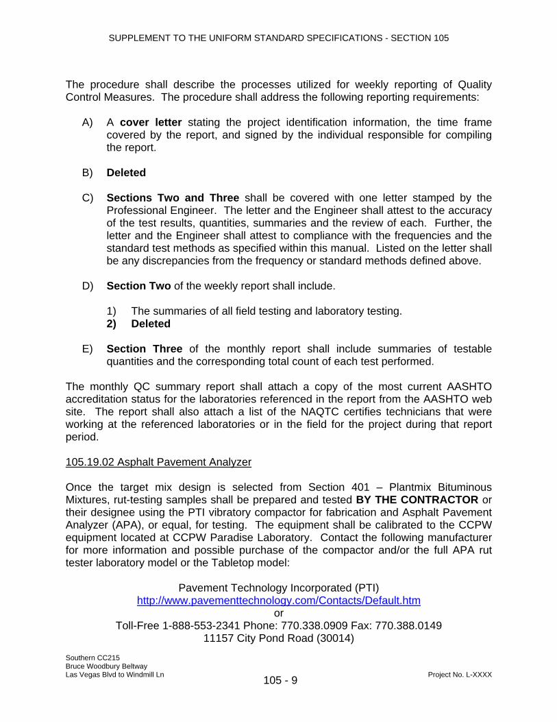
The procedure shall describe the processes utilized for weekly reporting of Quality Control Measures. The procedure shall address the following reporting requirements: A) A cover letter stating the project identification information, the time frame
covered by the report, and signed by the individual responsible for compiling the report.
B) Deleted C) Sections Two and Three shall be covered with one letter stamped by the
Professional Engineer. The letter and the Engineer shall attest to the accuracy of the test results, quantities, summaries and the review of each. Further, the letter and the Engineer shall attest to compliance with the frequencies and the standard test methods as specified within this manual. Listed on the letter shall be any discrepancies from the frequency or standard methods defined above.
D) Section Two of the weekly report shall include. 1) The summaries of all field testing and laboratory testing. 2) Deleted E) Section Three of the monthly report shall include summaries of testable
quantities and the corresponding total count of each test performed. The monthly QC summary report shall attach a copy of the most current AASHTO accreditation status for the laboratories referenced in the report from the AASHTO web site. The report shall also attach a list of the NAQTC certifies technicians that were working at the referenced laboratories or in the field for the project during that report period. 105.19.02 Asphalt Pavement Analyzer Once the target mix design is selected from Section 401 – Plantmix Bituminous Mixtures, rut-testing samples shall be prepared and tested BY THE CONTRACTOR or their designee using the PTI vibratory compactor for fabrication and Asphalt Pavement Analyzer (APA), or equal, for testing. The equipment shall be calibrated to the CCPW equipment located at CCPW Paradise Laboratory. Contact the following manufacturer for more information and possible purchase of the compactor and/or the full APA rut tester laboratory model or the Tabletop model:
Pavement Technology Incorporated (PTI) http://www.pavementtechnology.com/Contacts/Default.htm
or Toll-Free 1-888-553-2341 Phone: 770.338.0909 Fax: 770.388.0149
11157 City Pond Road (30014)
Southern CC215 Bruce Woodbury Beltway Las Vegas Blvd to Windmill Ln Project No. L-XXXX 105 - 9

SUPPLEMENT TO THE UNIFORM STANDARD SPECIFICATIONS - SECTION 105
P.O. Box 1184 (30015) Covington, GA Email: [email protected]
There are private laboratories that provide for this service. Upon request, the County can provide a name of a company. 105.19.03 MATERIAL SAMPLING The Contractor quality control program shall include as a part of the material sampling procedure the requirement that the sample be obtained from the Contractors quality control technician. It shall not be given to the Contractor from a subcontractor or material supplier unless the Contractor NAQTC technician observes and documents the sampling. 105.19.04 INDEPENDENT ASSURANCE SAMPLING The Contractor shall expect that up to three Independent Assurance (IA) samplings will occur in the duration of the contract. The IA is performed by the Engineer through the Quality Assurance section. In order to accomplish this, a copy of the pre-activity meeting and advance notification document needs to be faxed or emailed to 739-1558 or [email protected]. The sample acquisition will occur at the time scheduled by the Engineer. The IA sample shall be taken individually by QC, the QA and IA representative. The samples are to be combined and then split for each organization for the required contract testing. As a part of the review, the IA person will observe and document the sampling procedures. The test results for this sampling are to be transmitted as per the contract documents and a copy sent to the Clark County Public Works Construction Management Division Quality Assurance Section at 7361 W. Charleston Suite 130, Attention Michael Dunning. The results are not to be a part of the contract acceptance data. 105.19.05 CONTRACTOR INSPECTOR The Contractor shall provide a separate qualified person to perform the inspector duties other than the foreman or member of the crew. 105.19.06 QUALITY CONTROL COORDINATOR The Contractor shall have a person with sole duties are to coordinate the administration of the QC inspection and testing on the project. The QC program narrative and tables shall address the following: The Contractor shall name one qualified individual at the project site, titled as Quality Control Coordinator (QCC), whose sole responsibility is the full time administration,
Southern CC215 Bruce Woodbury Beltway Las Vegas Blvd to Windmill Ln Project No. L-XXXX 105 - 10

SUPPLEMENT TO THE UNIFORM STANDARD SPECIFICATIONS - SECTION 105
implementation, and performance of Contractor Quality Control Program. The Contractor shall provide a statement in their Quality Control Program that the Contractor shall submit to the Engineer for approval, the qualifications of any individual proposed as a replacement to the Quality Control Coordinator during the course of the project. 105.19.07 QUALITY CONTROL ADMINISTRATION A narrative shall be included in the Quality Control Program that fully describes the responsibility and level of authority of each key individual. The narrative shall also identify the Contactor’s person by Position Title who has authority to stop work that is not in conformance with the project plans and specifications. The suggested format for providing the information is similar to Table A that references the typical organization as displayed in Figure A. Suggested details are shown in Tables 1 through 7.
Table A - Typical Position Description Form
1 Position Number Position Title Name of Employee Name: 2 Stop-Work Authority Yes or No 3 Qualifications: 4 Certifications: 5 Scope of Work and Responsibilities: 6 Communication- Provide direct access for the following individuals:
7 Communication protocol:
To Whom What When
Southern CC215 Bruce Woodbury Beltway Las Vegas Blvd to Windmill Ln Project No. L-XXXX 105 - 11

SUPPLEMENT TO THE UNIFORM STANDARD SPECIFICATIONS - SECTION 105
QC Field/Lab Testing Technician
Position 1.06/07
QC InspectorPosition 1.05
Responsiple Person in-Charge (RPC)Position 1.03
Prof EngineerPosition 1.02
Principal RepresentativePosition 1.01
Quality Control CoordinatorPosiiton 1.04
Figure A Qualifications and experience requirements shall be provided for each QC position. The minimum experience requirements for selected positions are as follows: The Responsible Person-in-charge (RPC) shall have a minimum eight years experience in construction managing the type of construction implemented on the contract. The RPC shall have the ability to speak and read English and read and understand construction plans and specifications. The RPC shall have stop work authority. For the testing QC Laboratory, the Professional Engineer who is in responsible charge of the testing shall be a Nevada State licensed Civil Professional Engineer, with a minimum of five (5) years experience in construction materials. The inspectors shall have a minimum of 3 years of experience in the inspection of the particular type of construction work they are performing. The inspectors shall have the ability to speak and read English and read and understand construction plans and specifications. The Contractor shall provide documentation showing the inspector’s experience including references of previous projects(s), Engineers of those project(s), and companies who employed the inspector. Work experience documented shall include the major work activities included within this contract. The QCC shall have a minimum three years of experience in a supervisory Quality Control position and a total minimum of eight years on projects of similar size, scope, and complexity. The QCC shall have the ability to speak and read English and read and understand construction plans and specifications. The Contractor shall provide
Southern CC215 Bruce Woodbury Beltway Las Vegas Blvd to Windmill Ln Project No. L-XXXX 105 - 12

SUPPLEMENT TO THE UNIFORM STANDARD SPECIFICATIONS - SECTION 105
documentation showing the QCC’s experience including references of previous projects(s), Engineers of those project(s), and companies who employed the QCC. Work experience documented shall include the major work activities included within this contract. The QCC shall have or had a testing certification with NAQTC or other nationally recognized organization and experience in the inspection of construction installation. All QC Contractor and Subcontractors personnel shall be outlined by title, function, and name. Resumes of all RPC, QCC, PE, inspection and material testing personnel shall be included in the Quality Control Program. The Contractor shall verify that qualifications of each employee match those required by the position that individual will hold and will be valid for the duration of the project. If personnel will require re-certification during the contract duration, the Contractor shall indicate those personnel and the process for assuring that the recertification is accomplished. The Contractor shall identify “back-up” QC Inspectors in the initial Quality Control Program. If any individual is not listed at the beginning of the project, the normal submittal approval process and time frame will be required before that person may perform inspection duties. The Contractor shall complete the Position Description Form (Tables 1 through 7) for each position including Name, Signature, Discipline, Employer, Stop-Work Authority, Certifications, and Title as applicable. One form will be used per position per individual. The form will include all disciplines of work and the related certifications for which the individual is qualified. The inspection and testing staff utilized for a specific item of work may be comprised of any individual that has demonstrated competence and completed the appropriate form. Only QC Inspectors, technicians, or foreman with appropriate certifications will be used for that item of work. When multiple QC Inspectors are used for a common work item, the individuals allowed to inspect a specific item within the work will be identified during the Pre-Activity Meeting. However, all personnel must be established in the approved QC program.
Southern CC215 Bruce Woodbury Beltway Las Vegas Blvd to Windmill Ln Project No. L-XXXX 105 - 13
SUPPLEMENT TO THE UNIFORM STANDARD SPECIFICATIONS - SECTION 105
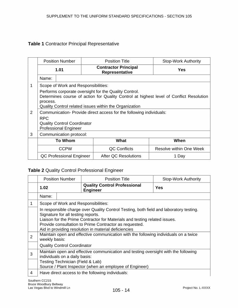
Table 1 Contractor Principal Representative
Position Number Position Title Stop-Work Authority
1.01 Contractor Principal Representative Yes
Name:
1 Scope of Work and Responsibilities: Performs corporate oversight for the Quality Control.
Determines course of action for Quality Control at highest level of Conflict Resolution process. Quality Control related issues within the Organization
2 Communication- Provide direct access for the following individuals: RPC
Quality Control Coordinator Professional Engineer
3 Communication protocol: To Whom What When
CCPW QC Conflicts Resolve within One Week
QC Professional Engineer After QC Resolutions 1 Day
Table 2 Quality Control Professional Engineer
Position Number Position Title Stop-Work Authority
1.02 Quality Control Professional Engineer Yes
Name:
1 Scope of Work and Responsibilities:
In responsible charge over Quality Control Testing, both field and laboratory testing. Signature for all testing reports. Liaison for the Prime Contractor for Materials and testing related issues. Provide consultation to Prime Contractor as requested. Aid in providing resolution in material deficiencies Maintain open and effective communication with the following individuals on a twice weekly basis: 2
Quality Control Coordinator
3 Maintain open and effective communication and testing oversight with the following individuals on a daily basis: Testing Technician (Field & Lab) Source / Plant Inspector (when an employee of Engineer)
4 Have direct access to the following individuals:
Southern CC215 Bruce Woodbury Beltway Las Vegas Blvd to Windmill Ln Project No. L-XXXX 105 - 14

SUPPLEMENT TO THE UNIFORM STANDARD SPECIFICATIONS - SECTION 105
Principal Representative
5 Communication protocol:
To Whom What When
RPC QC Conflicts - Investigation
Resolve Within 1 day of Test Completion or 3 days for other material issues
Quality Control Coordinator
Monthly Report of Field and Lab Results At time of Pay Estimate
Final Report of Field and Lab Results
Within 2 weeks from “Substantial Completion”
Deficiencies in Lab Test Results
Immediately upon completion of testing
QC Technician After Resolution 1 hour
Southern CC215 Bruce Woodbury Beltway Las Vegas Blvd to Windmill Ln Project No. L-XXXX 105 - 15

SUPPLEMENT TO THE UNIFORM STANDARD SPECIFICATIONS - SECTION 105
Table 3 Responsible Person in Charge (RPC)
Position Number Position Title Stop-Work Authority
1.03 Responsible Person in Charge (RPC) Yes
Name:
1 Scope of Work and Responsibilities: Expedite Conflict Resolution. Educate Lead / Foreman of responsibilities to the QC Program. Generate or advise QC coordinator to review, and forward Materials Submittals. Measurement and reporting of daily quantities. Maintain open and effective communication and testing oversight with the following individuals on a daily basis: 2
Quality Control Coordinator
4 Have direct access to the following individuals:
Principal Representative
5 Communication- Provide direct access for the following individuals:
Quality Control Inspector
6 Communication protocol:
To Whom What When Professional Engineer QC Conflicts Report within 1 Day Quality Control Coordinator QC Resolutions Report within 1 Hour
QC Inspector/Foreman Materials Delivery and Quantities Log Daily
Southern CC215 Bruce Woodbury Beltway Las Vegas Blvd to Windmill Ln Project No. L-XXXX 105 - 16
SUPPLEMENT TO THE UNIFORM STANDARD SPECIFICATIONS - SECTION 105
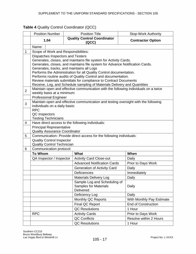
Table 4 Quality Control Coordinator (QCC) Position Number Position Title Stop-Work Authority
1.04 Quality Control Coordinator (QCC) Contractor Option
Name: 1 Scope of Work and Responsibilities:
Dispatches Inspectors and Testers Generates, closes, and maintains file system for Activity Cards. Generates, closes, and maintains file system for Advance Notification Cards. Generates, tracks, and maintains all Logs Performs the Administration for all Quality Control documentation. Performs routine audits of Quality Control and documentation. Review materials submittals for compliance to Contract Documents Receive, Log, and Schedule sampling of Materials Delivery and Quantities Maintain open and effective communication with the following individuals on a twice weekly basis at a minimum: 2
Professional Engineer
3 Maintain open and effective communication and testing oversight with the following individuals on a daily basis:
RPC QC Inspectors Testing Technicians
4 Have direct access to the following individuals: Principal Representative Quality Assurance Coordinator
5 Communication- Provide direct access for the following individuals: Quality Control Inspector Quality Control Technician
6 Communication protocol: To Whom What When QA Inspector / Inspector Activity Card Close-out Daily Advanced Notification Cards Prior to Days Work
Generation of Activity Card Daily Deficiencies Immediately Materials Delivery Log Daily
Sample Log and Scheduling of Samples for Materials Delivered
Daily
Deficiency Log Daily Monthly QC Reports With Monthly Pay Estimate Final QC Report End of Construction QC Resolutions 1 Hour RPC Activity Cards Prior to Days Work QC Conflicts Resolve within 2 Hours
Southern CC215
QC Resolutions 1 Hour
Bruce Woodbury Beltway Las Vegas Blvd to Windmill Ln Project No. L-XXXX 105 - 17

SUPPLEMENT TO THE UNIFORM STANDARD SPECIFICATIONS - SECTION 105
Table 5 Quality Control Contract or Material Source Inspectors Position Number Position Title Stop-Work Authority
1.05 Quality Control Contract or Material Source Inspectors Yes
Name:
1 Scope of Work and Responsibilities: Performs inspections and possibly testing. However if testing, must comply with NAQTC
field test module.. Reviews materials Testing Technician test results. Ascertain work compliance to Contract Documents. Responsible for Quality Control acceptance of work. Responsible for identifying deficient or Non-Compliant work. Will execute “stop work” authority when work or materials are found to be deficient and/or Non-Compliant. Responsible for identifying deficient or Non-Compliant work. Signature for Activity Card Inspection Section items. Measurement, Calculation, and reporting of Testable Quantities. Report deficiencies
2 Maintain open and effective communication and testing oversight with the following individuals on a daily basis:
Quality Control Coordinator Professional Engineer Testing Technician Source / Plant Inspector QA Inspector
3 Have direct access to the following individuals: RPC Quality Control Coordinator and/or RPC
4 Communication- Provide direct access for the following individual(s): Quality Control Technician 5 Communication protocol:
To Whom What When
QA Inspector Inspection Results Immediately
Testable Quantities Immediately
QC Conflicts Immediately Deficiencies Immediately Upon Scheduled
Inspection
QC Coordinator Activity Card
With Test Results attached at the end of the event. Will be completed by the end of the day.
Quality Control Coordinator and/or RPC QC Conflicts 2 Hours
Southern CC215 Bruce Woodbury Beltway Las Vegas Blvd to Windmill Ln Project No. L-XXXX 105 - 18

SUPPLEMENT TO THE UNIFORM STANDARD SPECIFICATIONS - SECTION 105
Table 6 Quality Control Field Testing Technician
Position Number Position Title Stop-Work Authority
1.06 Quality Control Field Testing Technician Contractor Option
Name:
1 Scope of Work and Responsibilities:
This individual is the “support” for the Quality Control Inspector. Verifies conformance of materials through testing. Advisor to Quality Control Inspector in regard to testing. Responsible for accurately testing, sampling, and reporting of results for construction materials. Responsible for identifying deficient or Non-compliant work, as related to testing. Responsible for notifying Quality Control and Quality Assurance of status of work, as related to testing
2 Maintain open and effective communication and testing oversight with the following individuals on a daily basis: Quality Control Coordinator Professional Engineer Quality Assurance Coordinator Inspector
3 Have direct access to the following individuals:
Quality Assurance Coordinator
4 Communication- Provide direct access for the following individuals: Quality Control Inspector Quality Control Lab Technician
5 Communication protocol:
To Whom What When QC/QA Inspector/Foreman Test results Immediately
Deficiencies Immediately Upon Failing Test or Observation
Informational Testing Before performing informational tests
QC Coordinator Test Results Attach to Activity Card at the end of the Event.
Southern CC215 Bruce Woodbury Beltway Las Vegas Blvd to Windmill Ln Project No. L-XXXX 105 - 19

SUPPLEMENT TO THE UNIFORM STANDARD SPECIFICATIONS - SECTION 105
Table 7 Quality Control Laboratory Testing Technician Position Number Position Title Stop-Work Authority
1.07 Quality Control Laboratory Testing Technician Contractor Option
Name: 1 Scope of Work and Responsibilities:
This individual is the “support” for the Professional Engineer. Verifies conformance of materials and work through testing. Advisor to Quality Control Inspector in regard to testing. Responsible for accurately testing, sampling, and reporting of results for construction materials. Responsible for identifying deficient or Non-compliant work, as related to testing. Responsible for notifying Quality Control and Quality Assurance of status of work, as related to testing.
2 Maintain open and effective communication and testing oversight with the following individuals on a daily basis:
Quality Control Coordinator Professional Engineer
3 Have direct access to the following individuals:
Quality Assurance Coordinator
4 Communication- Provide direct access for the following individuals: Quality Control Inspector
5 Communication protocol: To Whom What When Professional Engineer Test results Immediately
Professional Engineer Deficiencies Immediately Upon Failing Test or Observation
105.20 Payment For Contractor Quality Control Program Type B Payment for quality control shall be lump sum for all quality control efforts required to complete the work described in the general and special provisions and project plans, including the Contractor’s QC Plan, punch list and clean up. Preparer Note: The lump sum amount to be inserted into the bid schedule for preliminary estimating purposes shall be calculated as an amount equal to the number of contract calendar days times $1600.00. HOWEVER, before the project is advertised contact Michael Dunning at Construction Management to verify the Lump Sum amount to be entered in the bid form. For the purposes of this”quality control” item the term “day” shall mean “calendar day” unless otherwise stated. Southern CC215 Bruce Woodbury Beltway Las Vegas Blvd to Windmill Ln Project No. L-XXXX 105 - 20
SUPPLEMENT TO THE UNIFORM STANDARD SPECIFICATIONS - SECTION 105
The contract lump sum paid for quality control shall be full compensation for performing all required control of quality including, but not limited to, costs to develop the quality control program, management of the quality control program, on-site testing, on-site inspection and oversight, off-site source/production inspection, off-site source/production testing, laboratory testing of field samples, preparation of the weekly and monthly reports, submittal of the program, submittal of results and daily, weekly and monthly reporting of results. Any additional costs associated with performance of Quality Control shall be considered as the Contractor’s methods and means and those costs shall be included in and incidental to other items of work. No additional payment will be made for Quality Control for such incidental work. No additional payment for Quality Control will be considered for Owner Caused Delays. If the Contractor anticipates additional Quality Control expenses due to Owner Caused Delays they shall include such costs in the appropriate bid line item. In the event of non-excusable or excusable, non-compensable time extensions; no adjustment of the lump sum for Quality Control will be made. Payment for Quality Control measures necessary for Additional Work will be negotiated as part of the Construction Change Authorization. The Engineer may request additional testing with a value not to exceed a maximum of 10% for a given test type performed on the project at no increase in the lump sum payment. Progress billings shall bill for the daily value as calculated above, times the number of contract days in the billing cycle. In the event the contract is finished ahead of schedule, any remainder up to the original (or adjusted) lump sum amount will be paid on the Final Payment. Testing at a frequency greater than the minimum called for, other than at the direction of the Engineer, is considered to be a means and methods decision of the Contractor and as such is at the expense of the Contractor. In the event of improperly conducted Quality Control Program, the daily lump sum amount will be reduced by $50.00 per day per incident by the Engineer until resolved. An incident is defined as: • The use of an incorrect, or the improper execution of a test method. • The use of a non-qualified QC inspector (based on resumes or actions on the
project). • Improperly submitted reports. • Lack of timely resolution of deficiencies and non-compliances. • Non-conformance of the Quality Control Administration audit. The lump sum amount will be reduced in the event the frequency of testing is less than the minimum called for in the Quality System Manual. The amount of reduction will be Southern CC215 Bruce Woodbury Beltway Las Vegas Blvd to Windmill Ln Project No. L-XXXX 105 - 21

SUPPLEMENT TO THE UNIFORM STANDARD SPECIFICATIONS - SECTION 105
equivalent to the pro-rata reduction in testing frequency. If any given type of testing was conducted by a non-accredited laboratory, the payment for said type of testing will be suspended for 30 days to allow for rectification. If resolved within 30 days, the payment said type of testing will be released. If after 30 days, the laboratory cannot satisfy the Engineer, the Contractor shall replace the non-complying laboratory. If any given type of testing was conducted by a non-certified technician(s), such test(s) will be subject to non-payment of the lump sum line item and the Contractor shall also pay for the Quality Assurance testing until such time the certified technician is replaced. Specialized testing may be performed at the Clark County Public Works Construction Division Laboratory at 7361 West Charleston, Suite 130 in lieu of out sourcing only if the service is not available as specified in the special provisions. Fees shall apply, as indicated in Table 1, with payment directed to Clark County Treasurer Maintenance Account 202 delivered to Clark County Public Works Construction Division at 500 South Grand Central Parkway. The fees are specifically for the use of the equipment by the contractor and do not include Clark County labor.
Table 1 Clark County Lab Equipment Usage Fees
Description Fee Asphalt Pavement Analyzer $300 per test set
PTI Vibratory Compactor $75 per beam PTI Pugmill $75 per batch Hobart Mixer $50 per Batch Labor $100 per hour
Equipment and engineering/technician hours required for Quality Assurance investigation for Quality Control conflict resolution shall be reimbursed as per the table 1 fee schedule in special provision Section 112 Quality Control Administration Procedures. The fee(s) shall be payable to Clark County Treasurer Maintenance Account 202 delivered to Clark County Public Works Construction Division at 500 South Grand Central Parkway. 105.21 Value Engineering Proposals Value Engineering Proposals (VEP) may be submitted in writing for modifying the plans, specifications or other requirements of the contract for the purpose of reducing the total cost of construction without reducing design capacity or quality of the finished product. If accepted, net savings resulting from a VEP will be shared by the Department and the Contractor on a 50-50 basis. The requirements herein apply to all VEPs initiated and developed by the Contractor and which are identified as such at the time of submission. Nothing herein shall be construed as requiring consideration or approval of a VEP submitted hereunder. Southern CC215 Bruce Woodbury Beltway Las Vegas Blvd to Windmill Ln Project No. L-XXXX 105 - 22
SUPPLEMENT TO THE UNIFORM STANDARD SPECIFICATIONS - SECTION 105
Each VEP shall result in a net savings over the contract costs without impairing essential functions and characteristics of the item(s) or of any other part of the project, including but not limited to environmental considerations, service life, reliability, economy of operation, ease of maintenance, desired aesthetics and safety. Submit the following information with each VEP:
a) A statement that the proposal is submitted as a VEP; b) A statement concerning the basis for the VEP and benefits to the Department
together with an itemization of the contract requirements affected by the VEP; c) A detailed estimate of the cost under the existing contract and under the VEP; d) Proposed specifications and recommendations as to how such a VEP changes
are to be accomplished; and e) A statement as to the time by which a contract change order adopting the VEP
must be issued so as to obtain the maximum cost effectiveness. The VEP will be processed in the same manner as prescribed for any other proposal which would necessitate issuance of a contract change order. The Department may accept in whole or in part any VEP by issuing a contract change order which will identify the VEP on which it is based. The Department will not be liable for failure to accept or act upon any VEP submitted pursuant to these requirements nor for any delays to the work attributable to any such proposal. Until a proposal is effected by contract change order, remain obligated to perform under the terms and conditions of the existing contract. If an executed contract change order has not been issued by the date upon which the proposal specifies that a decision thereon should be made, or such other date as the Contractor may have subsequently specified in writing, such proposal shall be deemed rejected. The contract change order effecting the necessary contract modification will establish the net savings agreed upon, will provide for adjustment in the contract prices and will indicate the new savings to be equally divided between the Contractor and the Department. Absorb all costs incurred in preparing a VEP for submission. All reasonably incurred costs of reviewing and administering the VEP will be borne by the Department. The Department reserves the right to include in the agreement any conditions it deems appropriate for consideration, approval, and implementation of the proposal. The Contractor’s 50% share of the net saving shall constitute full compensation to him for effecting all changes pursuant to the agreement. Acceptance of the VEP and performance of the work thereunder will not change the contract time limit as a result of the VEP, unless specifically provided for in the contract change order authorizing the VEP. The Department expressly reserves the right to adopt a VEP for general use in contracts administered by the Department when it determines that said proposal is suitable for application to other contracts. VEPs identical or similar to previously
Southern CC215 Bruce Woodbury Beltway Las Vegas Blvd to Windmill Ln Project No. L-XXXX 105 - 23

SUPPLEMENT TO THE UNIFORM STANDARD SPECIFICATIONS - SECTION 105
submitted proposals will be eligible for consideration and compensation under these provisions if such proposals were not previously adopted for general application to other contracts administered by the Department. When a VEP is adopted for general use, compensation pursuant to these requirements will be applied only to those contracts awarded and for which the subject VEP has been submitted before the date of adoption of the specific VEP. Proposed changes in the basic design of a bridge or pavement type, traffic control plan, or changes which require different right of way limits, will not normally be considered as an acceptable VEP. The Engineer shall be the sole judge of the acceptability of a VEP. Subject to the provisions contained herein, the Department or any other public agency shall have the right to use all or part of any accepted VEP without obligation or compensation of any kind to the Contractor. In the event a VEP is accepted by the Department, the provisions of Subsection 104.02 which pertain to adjustment of contract unit prices due to alterations of contract quantities will not apply to items adjusted or deleted as a result of effecting the VEP by contract change order.
Southern CC215 Bruce Woodbury Beltway Las Vegas Blvd to Windmill Ln Project No. L-XXXX 105 - 24

SUPPLEMENT TO THE UNIFORM STANDARD SPECIFICATIONS - SECTION 105
CONSTRUCTION INTERFERENCES
CONTRACTOR'S RESPONSIBILITY
PER DWG
CASE II
ACTUAL
SHOWN ORNOTSHOWN ONDWG.
PER DWG.OR NOTSHOWN
CLASS 2> 4" NOM. DIA.
CLASS 1> 4" NOM. DIA.
CLASS 1> 4" NOM. DIA.
CLASS 1 OR 2< =4" NOM.
DIA.
CLASS 1> 4" NOM. DIA.
CLASS 2> 4" NOM. DIA.
ACTUAL
PER DWG
ACTUAL
ACTUAL
PER DWG
ACTUAL
CASE I CASE III
CASE IV CASE V
ACTUAL
NOT SHOWN ONDWG.
CHANGE IN WORKCASE VI
Southern CC215 Bruce Woodbury Beltway Las Vegas Blvd to Windmill Ln Project No. L-XXXX 105 - 25

SUPPLEMENT TO THE UNIFORM STANDARD SPECIFICATIONS - SECTION 106
SECTION 106
CONTROL OF MATERIALS 106.01 Source Of Supply And Quality Requirements Paragraph 7 is changed to read as follows: The Contractor shall furnish without charge such samples as may be required. Inspection and tests may be performed by the engineer or his designated representative in accordance with Subsections 105.20, but it is understood that such inspections and tests, if made at any point other than the point of incorporation in the work, in no way shall be considered as a guarantee of acceptance of such materials nor of continued acceptance of material presumed to be similar to that upon which inspections and tests have been made. The following subsections are added: 106.01.01 Content Of Submitted Materials List Each individual material being submitted to the Engineer shall be accompanied by a Cover Sheet. The contents of the Cover Sheet shall include the following:
1. Contractor’s Name and Address, including Phone and Fax numbers 2. Project Name 3. Package Number (Numbering shall be per Figure 1 below for listed items, all
other items will use the bid item prefix as the Package Number.) 4. Submittal Number (Sequential number inside of a particular Package) 5. Revision Number (Sequential number for each re-submit) 6. Intended use (description of the specific use or uses of the material on the
project) 7. Indication of “Or Equal” or “Substitution” as appropriate 8. Date 9. Number of Copies Sent (attached behind the Cover Sheet)
a. Minimum of one (1) Original and six (6) additional copies must be attached.
b. Clark County will retain the Original and two (2) copies. c. If Contractor requests additional copies to be returned, Clark County
will accommodate two (2) additional copies, up to a total of (9) documents maximum.
10. Printed Name and Signature of Submitting individual 11. Printed name and Signature of Responsible Person in Charge (RPC)
When more than one material is being submitted at one time, each individual material shall have an individual Cover Sheet.
Southern CC215 Bruce Woodbury Beltway Las Vegas Blvd to Windmill Ln Project No. L-XXXX 106 - 1

SUPPLEMENT TO THE UNIFORM STANDARD SPECIFICATIONS - SECTION 106
Figure 1 Table of Submittal Package Number
Section Package Number Description
100 General Items 100.01 SWPPP Permit 100.02 NDPES Permit 100.03 Air Quality Permit 100.04 Rolling Stock Permit 100.05 Emergency Contact List 103 Awards and Execution of Contract 105 Control of Work 105.01 QC Plan and Amendments 105.02 QC Monthly Reports 107 Legal Relations and Responsibility to the Public 107.01 Property Owner Permission Letters 108 Prosecution and Progress 108.01 Schedules 109 Measurements and Payments 109.01 Pay Estimates 109.02 Force Account 302 Aggregate Base Courses 302.01 Type II 624 Accommodations for Public Traffic 624.01 Traffic Control Plans 900 Project Closeout 900.01 QC File Turnover 900.02 Punchlist Completion 900.03 QC/QA Personnel Data Sheets NOTE: All other items will use the bid item prefix as the Package Number
106.01.02 Accuracy Of Content The responsible person in charge shall attest to the content of the submitted materials have been reviewed against the Contract Documents, and that the materials are in compliance thereto. Submitted materials that are to be evaluated as “Or Equal” or “Substitution” shall be reviewed for accuracy and sufficiency of back-up materials to enable the Engineer to make the determination. 106.01.03 Submission Of Multiple Materials Concurrently A “Transmittal or Cover Page shall accompany any group of two (2) or more submitted materials. The Transmittal shall include the following information:
1. Contracting company name and address, including phone and fax number 2. Project name
Southern CC215 Bruce Woodbury Beltway Las Vegas Blvd to Windmill Ln Project No. L-XXXX 106 - 2
SUPPLEMENT TO THE UNIFORM STANDARD SPECIFICATIONS - SECTION 106
3. Bid number 4. Listing of submitted materials attached including package and submittal
numbers 5. Date 6. Printed name and signature of responsible person in charge
106.02 Local Materials Local material is rock, sand, gravel, earth, or other mineral material, other than local borrow or selected material, obtained or produced from sources in the vicinity of the work specifically for use on the project. Local material does not include materials obtained from established commercial sources. Local materials shall be furnished by the Contractor from any source the Contractor may elect, except when a mandatory source is designated in the Special Provisions. Aggregates for base, surface and concrete may be the products of approved commercial producers, provided they meet specification requirements. The furnishing of local materials from any source is subject to the provisions of Subsection 102.05, “Examination of Plans, Specifications, Contract Documents, and Site of Work,” and 106.03, “Possible Local Material Sources.” Material deposits shall not be excavated at locations where their resulting scars will present an unsightly appearance from any street or highway, unless such excavation is approved in writing by the Engineer. Generally deposits other than those indicated in the “Materials Information” packet will not be approved if located within one thousand (1,000) feet of right-of-way line. In any case the Contractor’s pit operations shall not encroach within twenty-five (25) feet of the right-of-way. Payment will not be made on material obtained in violation of these provisions. The Contractor shall, at his own expense, make any and all arrangements necessary for hauling over local, public or private roads or property from any source. Full compensation for furnishing all labor, materials, tools, equipment and incidentals, for doing all the work involved in conforming to the provisions in this Subsection and for furnishing and producing materials from any source shall be considered as included in the price paid for the contract item of work involving such material and no additional compensation will be allowed therefore. 106.04 Samples And Tests Paragraph 1 is changed to read as follows: Except as provided in Subsection 106.05, “Certificates of Compliance,” all materials will
Southern CC215 Bruce Woodbury Beltway Las Vegas Blvd to Windmill Ln Project No. L-XXXX 106 - 3

SUPPLEMENT TO THE UNIFORM STANDARD SPECIFICATIONS - SECTION 106
be inspected, tested, and accepted as per Subsection 105.19 and 105.20 before incorporation in the work. Any work in which untested and unaccepted materials are used without approval or written permission of the Engineer shall be treated as provided in Subsection 105.12. The following is added after the first paragraph: All field testing technicians shall be Nevada Alliance for Quality Transportation Construction (NAQTC) certified, including ACI certification, January 1, 2002. Information regarding training, examinations and certification is available from the Nevada T2 Center/257-NAQTC, University of Nevada, Reno, 1664 N. Virginia Street, Reno, Nevada, 89557-0179. Paragraph 5 is changed to read as follows: When the Engineer elects to take, or specifications require that samples be taken at a production plant, sampling of aggregates shall be by “belt cut” from a stopped conveyor or may be by mechanical sampling device built into the production plant. Any mechanical sampling device shall be approved by the Engineer prior to starting the respective phase of the project, or shall have been approved as part of a prior plant inspection by the Engineer or his representative. The sampling device shall be so constructed to provide for simultaneous “cutting” of the entire section of material being discharge or conveyed, and so constructed that small representative samples may be taken frequently and these samples combined to form the complete sample. The reference method for the procedure shall be a “belt cut” sample taken from a stopped conveyor belt. Paragraph 6 is changed to read as follows: The Contractor, at his own expense, shall acquire the sample from the plant without delay upon the Engineers request. Samples of the finished product of the plant shall be obtained prior to or as material leaves the conveyor belt for the bin or stockpile. The samples shall be delivered by mechanical means to a point on the ground or other safe and accessible spot satisfactory to the Engineer. Test results from the samples taken will be furnished by the Engineer to the Contractor’s Representative upon his request. Sub paragraphs (d) and (f) of paragraph 7 shall be changed to read as follows: (d) Bituminous mixtures and aggregates for plantmix bituminous open-graded
mixtures shall be sampled at the production plant. Aggregates shall be sampled prior to the introduction of additives or bituminous materials by the means outlined above. Bituminous mixtures shall be sampled at the point of discharge from the mixer drum. Samples of individual aggregate components shall be taken prior to blending at the bins or stockpiles.
(f) Bituminous mixtures and aggregates for plantmix bituminous mixtures (base or
Southern CC215 Bruce Woodbury Beltway Las Vegas Blvd to Windmill Ln Project No. L-XXXX 106 - 4
SUPPLEMENT TO THE UNIFORM STANDARD SPECIFICATIONS - SECTION 106
surface) shall be sampled at the production plant. Aggregates shall be sampled prior to the introduction of additives or bituminous materials by the means outlined above. Bituminous mixtures shall be sampled at the point of discharge from the mixer drum. Samples of individual aggregate components shall be taken prior to blending at the bins or stockpiles.
106.07 Plant Inspection Paragraph 1 is changed to read as follows: The Engineer may inspect the production of material or manufacture of products at the source of supply. The Contractor and material producer shall assure the Engineer of their cooperation and assistance to perform plant inspection prior to production of materials for the project. The Engineer or his authorized representative shall have free entry at all times to such parts of the plant as concerns the manufacture or production of the materials. Adequate facilities shall be furnished free of charge to make the necessary inspection. 106.12 Foreign Materials Subsection 106.12 Foreign Materials from the NDOT Standard Specifications for Road and Bridge Construction is hereby incorporated by reference.
Southern CC215 Bruce Woodbury Beltway Las Vegas Blvd to Windmill Ln Project No. L-XXXX 106 - 5

SUPPLEMENT TO THE UNIFORM STANDARD SPECIFICATIONS – SECTION 107
SECTION 107
LEGAL RELATIONS AND RESPONSIBILITIES TO THE PUBLIC
107.07 Traffic And Access The following is added to the fourth paragraph: The Contractor shall not close down any two consecutive Citizens Area Transit (CAT) bus stops on routes for buses traveling in the same direction. There are seven bus stops within the project limits at the following approximate locations and directions of travel: LOCATION DIRECTION Warm Springs Rd East of Puritan Ave Eastbound Warm Springs Rd West of Paradise Rd Westbound Warm Springs Rd East of Paradise Rd Eastbound Warm Springs Rd East of Marilissa Ln Eastbound Warm Springs Rd West of Abbeyville Dr Westbound George Crockett Rd East of Placid St Northbound George Crockett Rd East of Bermuda Rd Northbound The Contactor shall relocate existing bus signs at designated areas into proposed sidewalk, utilizing the bid item “Relocate Traffic Sign” in Section 627. Proposed bus signs at designated bus stop locations will be placed by the Clark Count Traffic Division of the Public Works Department. Temporary bus stops may be considered upon approval by the Regional Transportation Commission. The Contractor may call David Yancy at 676-1731 with any questions. A map of bus stop locations may be obtained from the Regional Transportation Commission. The last paragraph is changed to read as follows: The Contractor shall comply with all requirements contained in Section 624 and 625 of the Standard Specifications and with the supplemental requirements contained herein, except that no direct payment shall be made to the Contractor for signing and/or detours unless otherwise specified herein. The Contractor, as required by the Engineer, shall provide and station competent flaggers whose sole duties shall consist of directing the movement of public traffic either through or around the work. Traffic work zone technicians on the project must be certified in work zone traffic control at least at the “Technician” level by ATSSA, IMSA, or NICET. Southern CC215 Bruce Woodbury Beltway Las Vegas Blvd to Windmill Ln Project No. L-XXXX
107 - 1
SUPPLEMENT TO THE UNIFORM STANDARD SPECIFICATIONS – SECTION 107
Where necessary or required for the convenience of the public or individual residents at street crossings, alleys, or at private driveways, the Contractor shall provide suitable temporary bridges over unfilled excavations, except in such cases as the Contractor shall secure permission from the Engineer to omit such temporary bridges. All such bridges shall be maintained in service until after the Contractor has complied with all of the specifications governing the work prior to backfilling. Temporary bridges for street crossings shall conform to the requirements of the authority having jurisdiction in each case, and shall submit designs for approval by said authority as may be required. Steel plates used on this project must be capable of carrying the heaviest loads utilizing the roadway. When the Contractor’s construction operations encroach upon a sidewalk, walkway, or cross walk area, the Contractor shall take special precautions to protect the pedestrian’s safety including provisions to separate pedestrian traffic from the work area. Pipe stockpiled along pipeline alignments shall be within 1,000 feet of the Contractor’s laying operations. Pipe strung within street right-of-way that is to remain one night or more shall be protected by barricades spaced at intervals not exceeding 50 feet. The following subsections are added: 107.07.01 Traffic Control Regulations All traffic and/or traffic control devices under this contract shall be provided, maintained, and/or controlled as specified in this section and in the “Manual on Uniform Traffic Control Devices”, latest edition, the “Guidelines for Traffic Control in Work Zones” – 1997 edition and the “Uniform Standard Drawings for Public Works’ Construction Off-Site Improvements, Volume 1,” dated December 2000, as revised. The “Guidelines for Traffic Control in Work Zones” may be obtained for $3.00 from the University of Nevada, Reno, Transportation of Technology Transfer Center, College of Engineering/257, Reno, Nevada 89557-0179, or may be obtained online at http://www.t2.unr.edu/ . If the Contractor, at any time, fails to maintain traffic and/or traffic control devices as specified in the above documents or elsewhere by these specifications, the Engineer will immediately notify the Contractor in writing of such non-compliance. If the Contractor fails to remedy unsatisfactory maintenance within two (2) hours after receipt of such notice, the Engineer may immediately proceed to perform such maintenance, and the entire direct cost of the maintenance will be deducted from money due or to become due the Contractor. Southern CC215 Bruce Woodbury Beltway Las Vegas Blvd to Windmill Ln Project No. L-XXXX
107 - 2

SUPPLEMENT TO THE UNIFORM STANDARD SPECIFICATIONS – SECTION 107
If, in the opinion of the Engineer, a condition develops that is dangerous to public safety, such condition may be immediately remedied with whatever means is available to the owner and the cost of this maintenance will be deducted from money due or to become due to the Contractor. Further, each instance of failure to remedy unsatisfactory maintenance within two (2) hours of notification will result in a deduction of one day’s value of the traffic control pay item from the lump sum. One day’s value is determined by dividing the lump sum amount bid by the number of working or calendar days (whichever is applicable) allowed for the project. This sum is in addition to any direct costs incurred by the Contracting Agency to remedy unsatisfactory maintenance. 107.07.02 Traffic Control Requirements The Contractor will also, as a minimum, provide the following traffic control measures: Temporary traffic lanes must be delineated using either paint or traffic tape, excepting that paint may only be used on pavement to be replaced or overlaid as part of this contract. The tape shall conform to State of Nevada specifications. The temporary pavement striping shall be by pilot line method. The tape shall be 6-inches wide and 4 feet long and spaced every 40 feet. The color of the tape shall match the color of the line that it replaces. The double yellow line shall have two pieces of tape side by side with a 4-inch space between, and spaced to the increments above. Painted temporary traffic lines shall be 6-inches wide and shall be continuous or intermittent in accordance with the MUTCD. Existing lines either painted or raised pavement markers, that conflict with required temporary lines shall be effectively removed in such a manner to leave no residue or other trace of the former line that may be misconstrued by a driver to be a traffic line under any condition of daylight, darkness and wetness of pavement. At the completion of the project, the Contractor shall install additional pilot lines using 4-inch square pieces of tape to show the alignment of any permanent lines that were destroyed during construction. It shall be the responsibility of the Contractor to remark said lines. This 4-inch square tape shall be removed just prior to the installation of the permanent lines. Type III B barricades shall be used to protect all approaches to sites of excavation. The Type III B barricades shall be constructed from PVC (weighted) pipe to State of Nevada specifications.
Southern CC215 Bruce Woodbury Beltway Las Vegas Blvd to Windmill Ln Project No. L-XXXX
107 - 3

SUPPLEMENT TO THE UNIFORM STANDARD SPECIFICATIONS – SECTION 107
Flaggers must be used to assist trucks for safe ingress and egress whenever truck movements may interfere with safe passage through the work zone. In addition flaggers shall be used whenever the Engineer deems it necessary for safety purposes. If, in the opinion of the Engineer, a condition develops or exists that is dangerous to the safety of the general public, concrete barrier rails and fencing shall be used around the work site, excavations, trenches for underground utilities, and/or stockpiled materials. The barrier rails and fencing shall be maintained until the Engineer determines that the hazard no longer exists. Portable concrete barrier rail (jersey rail) shall be used to separate travel lanes from excavations when any excavation remains open and:
a. Exceeds one foot in depth, b. Exceeds one foot in width, c. Is sloped steeper than 4:1, and d. Is less than 18 feet from the nearest travel lane.
Fencing shall be used around open trenches exceeding 2’ in depth. The fencing may be placed on top of concrete barrier rails. Type II barricades used for delineation shall have Type C steady burn lights. All barricades used for closures shall have Type A lights. Type B lights shall be used with appropriate advance warning signs. 107.07.03 Traffic Control And Barricade Plan The Contractor shall submit a written and diagramed 24” x 36” “Traffic Control and Barricade Plan” to the Engineer no later than fourteen (14) calendar days prior to proposed use. Six (6) copies of the plan shall be submitted as a submittal directly to the Project Manager, who will review it for conformance to the contract documents, the MUTCD, and “Guidelines for Traffic Control in Work Zones”. No monies for “Traffic Control” shall be deemed to be earned until Contractor obtains approval of a “Traffic Control and Barricade Plan.” The total sum subsequently paid for “Traffic Control” shall be the lump sum amount bid minus a day’s value, as determined in accordance with 107.07.05, for each day after the Notice to Proceed that the Contractor fails to obtain approval for the “Traffic Control and Barricade Plan.” Further, work items requiring traffic control devices to be placed in the traveled way will be allowed to proceed until the Contractor has an approved “Traffic Control and Barricade Plan” for such work. The “Traffic Control and Barricade Plan,” using subsection 104.04 of the Special Provisions as a guideline, shall show as a minimum the following items:
1. All advance warning signs and arrow boards; Southern CC215 Bruce Woodbury Beltway Las Vegas Blvd to Windmill Ln Project No. L-XXXX
107 - 4
SUPPLEMENT TO THE UNIFORM STANDARD SPECIFICATIONS – SECTION 107
2. Method for protecting excavations and work sites; 3. Method of barricading at intersections; 4. Delineation patterns, length, etc., (including laterals); 5. All regulatory signs; 6. All warning signs within delineation; 7. Driveway access plan and business access signage; 8. Method for protecting pedestrians; 9. Provisions for emergency vehicle access at all times. 10. Lane widths and transitions’ and 11. 24-hour emergency telephone number 12. Days and time frame(s) the restriction will be in effect. 13. Proposed bus stop closures and relocations.
The above described plan must conform to the Special Provisions Section 625 contained herein as well as the latest revisions of the “Guidelines for Traffic Control in Work Zones’ – 1997 edition,” and the “Manual on Uniform Traffic Control Devices”, latest edition, for all traffic control methods, devices, and appurtenances. The Contractor is required to post with the Contracting Agent all information relative to any subcontractor for barricade control, including: Name of firm, address of firm, telephone number of firm, name of responsible agent for the project, and a 24 hour number for emergency response. All traffic must display The 24-hour contact number of the traffic control (sub) contractor on their reverse side, along with an identifying name, initials or logo. The “Traffic Control and Barricade Plan” must be completed to the Engineer’s satisfaction and all traffic control devices installed according to the approved plans before construction begins. 107.07.04 Traffic Control Plan For Highway Work Zones The Contractor may utilize the “Traffic Control Plans for Highway Work Zones” as shown in the Standard Drawings in lieu of preparing a “Traffic Control and Barricade Plan” per Subsection 107.07.03. If he so chooses, the Contractor shall submit to the Engineer, a copy of which proposed traffic control plans (TCPs) he is proposing to utilize, along with the construction phase or work activity and duration for each proposed TCP used. The Contractor is required to post with the Contracting Agent all information relative to any subcontractor for barricade control, including: Name of firm, address of firm, telephone number of firm, name of responsible agent of the project, and a 24-hour number for emergency response.
Southern CC215 Bruce Woodbury Beltway Las Vegas Blvd to Windmill Ln Project No. L-XXXX
107 - 5

SUPPLEMENT TO THE UNIFORM STANDARD SPECIFICATIONS – SECTION 107
The proposal for utilizing the Standard Drawing TCP must be completed and approved by the Engineer and all traffic control devices installed according to the TCP’s before construction begins. 107.07.05 Traffic Control Measurement And Payment Measurement for payment for traffic control shall be per lump sum for all traffic control required to safely perform the work described in the general and special provisions and the project plans, including punch list and clean up. The contract lump sum paid for traffic control shall be full compensation for performing all required control of traffic including barricading, signing, temporary fencing, project signs, temporary lane delineation, arrow boards, removal of conflicting makings, access and flag persons, fencing, trench plates, temporary bridges, concrete barrier to protect trenches, as specified herein, and as required by the Engineer. The lump sum payment for traffic control shall include all weekends, holidays and non-working days encountered during the duration of the contract including any days required for completion of corrective punch-list items. 107.18 Furnishing Right-Of-Way The following is added to this subsection:
(a) Lands or rights-of-way for the work to be constructed under the contract will be provided by the Owner as shown on the Drawings. Nothing contained in the Specifications of Drawings shall be interpreted as giving the Contractor exclusive occupancy of the lands or rights-of-way provided. Any additional lands or rights-of-way required for construction operations shall be provided by the Contractor at his own expense.
(b) The Contractor shall not enter nor occupy with men, equipment, or
materials any lands outside the rights-of-way or easements shown on the Drawings without the written consent of the owner of the property. Evidence of written permission to occupy lands outside those rights-of-way shown shall be presented to the Engineer prior to entry upon said land by the Contractor.
PLEASE DISCUSS THE FOLLOWING WITH THE CONSTRUCTION MANAGEMENT DIVISION OF PUBLIC WORKS TO DETERMINE IF PUBLIC NOTIFICATION FOR THE PROJECT SHOULD BE REQUIRED. 107.22 Public Relations And Notifications
Southern CC215 Bruce Woodbury Beltway Las Vegas Blvd to Windmill Ln Project No. L-XXXX
107 - 6

SUPPLEMENT TO THE UNIFORM STANDARD SPECIFICATIONS – SECTION 107
Seventy-two (72) hours prior to commencement of construction, the Contractor will notify, in person, all property owners and/or businesses which will be effected by the construction operation and will install “No Parking” signs at no more than 250 foot intervals along each side of the road where vehicle removal is required. Whenever personal notification is not possible, the Contractor, at his expense, shall reproduce and distribute written or printed notification in the form of a leaflet, door-hanger, etc., work shall be considered as subsidiary to the other related items of work and no separate payment be made therefore. This notification shall contain information such as the approximate date and time of construction, brief explanation of work, vehicle removal instructions. Contractor’s name, business address, and 24-hour telephone number of the Contractor or one of his agents. After notification by the Contractor, the Engineer will make any arrangements necessary to remove vehicles remaining in the roadway at the time of construction.
Southern CC215 Bruce Woodbury Beltway Las Vegas Blvd to Windmill Ln Project No. L-XXXX
107 - 7

SUPPLEMENT TO THE UNIFORM STANDARD SPECIFICATIONS – SECTION 108
SECTION 108
PROSECUTION AND PROGRESS
108.03 Prosecution And Progress This subsection is revised to read as follows: The Contractor shall be responsible for planning, scheduling and reporting the progress of the work to ensure timely completion of the contract. The Contractor shall submit an anticipated Schedule in two parts, based upon the Sequence of Construction shown in the project plans or in these Special Provisions, in accordance with the following: A. Part I shall be a preliminary Schedule and shall be submitted prior to or at the
pre-construction conference for the Engineer's acceptance. It shall be a schematic (arrow) diagram or precedence diagram, showing the work stages and operations for all activities required by the contract. The diagram shall be in sufficient detail to allow day-to-day monitoring of the Contractor's operations. Along with the preliminary Schedule, the Contractor shall include his calendar for the contract period which shall show work days, calendar days and dates. The diagram shall include four to ten milestone events as identified by the Contractor and accepted by the Engineer.
B. Part II shall be submitted for the Engineer's acceptance within fifteen (15)
calendar days after Part I has been accepted by the Engineer. This second Schedule shall include a complete critical path Schedule to cover the Contractor's anticipated time Schedule. The Schedule shall include a detailed network diagram acceptable to the Engineer with the following features:
1. It shall be time-scaled in calendar days. All activities shall be plotted on
their anticipated early start and finish dates. Unless approved by the Engineer, activities shall not exceed 15 working days in length. The plot shall have a size and scale acceptable to the Engineer.
2. It shall show the order and interdependence of activities and the sequence
of work as reflected in the Schedule Report specified in (B)(7) below. The critical activities shall be prominently distinguished on all reports by the use of color or other means acceptable to the Engineer.
3. It shall include, in addition to all construction activities, such tasks as
mobilization, demobilization, submittal and approval of samples of materials and shop drawings, procurement of significant or long-lead time materials
Southern CC215 Bruce Woodbury Beltway Las Vegas Blvd to Windmill Ln Project No. L-XXXX 108 - 1
SUPPLEMENT TO THE UNIFORM STANDARD SPECIFICATIONS – SECTION 108
and equipment fabrication of special items, installation and testing and interfacing with other projects.
4. The activities shall be sufficiently detailed so that a reviewer can follow the
sequence. For example, the activities shall show forming, reinforcing, and placement of concrete on the calendar days they are anticipated to be performed.
5. The diagram shall show for each activity the preceding and following event
numbers or activity numbers, the activity description, the total float, if any and the anticipated duration of the activity in working days.
6. The activities shall be organized and described so as to conform to the
contract bid items, as closely as possible. Activity descriptions shall be unique and specific with respect to the type of work and location.
7. The diagram shall be accompanied by a Schedule Report of the network
with a tabulation of the following data for each activity: a. Preceding and following event numbers or activity number. b. Activity description c. Activity duration d. Earliest start date e. Earliest finish date f. Latest start date g. Latest finish date h. Total float times i. Responsibility for activity - e.g., Contractor, subcontractor, supplier, etc. j. A balanced resource loading for each activity listing personnel and
equipment anticipated to accomplish the activity. Personnel should be identified as the number of each trade anticipated. Equipment shall be identified by type and, if known, by model/size.
k. Contractor shall be responsible for including in the balanced resource loaded schedule all subcontractors designated for completing 5 percent or more of the total contract value.
C. The Contractor shall make updated Schedules and Reports under the following
circumstances or as requested:
1. The Contractor shall submit a monthly report of actual construction progress with the monthly pay request by updating his Schedule Report to reflect all complete and in progress activities on the project. All negative float shall be explained in detail. If, in the opinion of the Engineer, the detailed network diagram requires revision, either wholly or in part, he shall so direct the Contractor and the Contractor shall submit such revision within ten (10) calendar days.
Southern CC215 Bruce Woodbury Beltway Las Vegas Blvd to Windmill Ln Project No. L-XXXX 108 - 2

SUPPLEMENT TO THE UNIFORM STANDARD SPECIFICATIONS – SECTION 108
2. The monthly report also shall show the activities or portions of activities
completed during the one (1) month reporting period and the portions completed on the project to date, showing actual start and finish dates plus all future activities.
3. The monthly report shall state the amount and percentage of revenue
actually earned as of the report date. 4. The Monthly Report shall be accompanied by a narrative description of job
progress, problem area, current and anticipated delaying factors and their expected effect, and any corrective actions proposed or taken. The narrative description shall also clearly identify any departures from earlier Schedules, including, but not limited to, changes in logical sequence or logical ties, constraints, changes in activity durations and changes, additions or deletion in event numbers, activity numbers, and activity descriptions and resource combinations. The reasons for each departure shall be included in the narrative description. The Engineer must approve any additions or deletions or milestone events.
5. The Monthly Report shall include a summary of all activities sequenced by a
total float from least to greatest float and ordered by early start. 6. The required Schedules and Report shall be submitted to the Engineer as
follows: a. Part I (Preliminary Schedule) - 7 originals b. Part II (Detail Network Diagram) - 7 originals c. Revisions to Part II - 7 originals d. Monthly Report - Original plus 3 copies of the narrative
7. The Monthly Report shall include a detailed predecessor/successor analysis showing the predecessors, successors, logic ties, and constraints for each activity Schedule. These activities shall be ordered by event number or activity number from least to greatest.
8. All Extra Work shall be shown on an updated Schedule.
The automated system software shall be Primavera or approved equal. The Contractor shall furnish an unopened licensed disc package of the software to the Engineer for use during the duration of the project. The software shall be IBM PC compatible. No measurement or direct payment will be made for Contractor costs relating to preparation and submission of Schedules and Reports and revisions thereto, the cost being considered as included in the prices paid for contract items. Southern CC215 Bruce Woodbury Beltway Las Vegas Blvd to Windmill Ln Project No. L-XXXX 108 - 3
SUPPLEMENT TO THE UNIFORM STANDARD SPECIFICATIONS – SECTION 108
Failure of the Contractor to comply with the Part 1, Part II or monthly updated Schedule and Report requirements specified herein, will be grounds for the Engineer to deduct ten (10) percent of the monthly progress payments, until the Contractor is in compliance. Upon compliance, this amount will be paid to the Contractor in the next Scheduled monthly estimate. Float time is not for the exclusive use or benefit of either the Department or the Contractor. Extension of time for performance may be granted for delays caused solely by action or inaction by the Contracting Agency to the extent that equitable time adjustment for the activity affected exceeds the total float of the project, or where an impact on the contract completion can be shown. Acceptance of the Contractor's Schedules by the Engineer is not to be construed as relieving the Contractor of his obligation to complete the work within the contract item; or as granting, rejecting, or in any other way acting on the Contractor's requests for adjustments to the date for completing contract work, or claims for additional compensation. Such requests shall be processed in strict compliance with other relevant provisions of the contract. The Contractor shall participate in a review and evaluation of the proposed Part I, Preliminary Schedule and Part II Schedule and monthly updated Schedule by the Engineer. Any revisions necessary as a result of the review shall be submitted for acceptance to the Engineer within ten (10) calendar days after the review. The accepted Part II Schedule shall then be used by the Contractor for planning, organizing, executing, and directing the work and for report progress of work accomplished. The Contractor shall furnish a copy of the Part II Schedule and monthly updated Schedule on a 3 ½ inch floppy disk or CD-ROM to the Engineer for project use. 108.04 Limitations of Operations Add the following paragraphs to this subsection: Contractor’s operations shall be restricted to areas shown on the Drawings which depict the limits of construction and/or right-of-way. Contractor shall limit disturbance to the work area. At no time shall materials and supplies be stored or stockpiles within thirty feet of a travel lane unless separated by guardrail or concrete barrier rail. Comply with related requirements specified in Section 100 and Section 624 of these Special Provisions. Work that is not within the travel way, will not delay existing traffic, does not conflict with the work zone traffic control in effect in current or future phases, may be constructed in earlier phases.
The phasing and staging plan shown in the plans and specification is one approach of constructing the project. The contractor may elect to prosecute the work differently than Southern CC215 Bruce Woodbury Beltway Las Vegas Blvd to Windmill Ln Project No. L-XXXX 108 - 4

SUPPLEMENT TO THE UNIFORM STANDARD SPECIFICATIONS – SECTION 108
depicted. It shall be the contractor’s sole responsibility to assure the constructability of their approach.
Multiple shifts may be necessary to complete the work within the allotted time limitations. The contractor shall provide a noise abatement plan to the OWNER for review and approval in accordance with Section 637 of the Special Provisions. The number of lanes on I-215 shall not be reduced during the hours of 6:00 a.m. and 9:00 p.m. unless approved in writing by the OWNER. One lane in each direction may be taken at any other time. Liquidated Damages will be assessed in accordance with Section 108.09 for failure to adhere to the time limitations above. The number of lanes on the Airport Connector shall not be reduced from that shown on the Phasing and Staging Plans unless approved in writing by the OWNER. All ramps must remain open unless otherwise noted on the plans or in these Special Provisions. Roadway closures will not be permitted unless otherwise noted on the plans or in these Special Provisions or unless approved in writing by the OWNER. Erection of steel girders shall be completed between the hours of 10:00 pm and 6:00 am. Traffic on the crossing roadway will be detoured in accordance with a plan submitted by the contractor and approved by the Engineer at least fifteen days prior to beginning this work. Alternatively, and only with approval of the OWNER, traffic may stopped and held for no more than 30 minutes by the law enforcement such as the Nevada Highway Patrol. If approved, the Contractor shall be responsible for all coordination necessary with law enforcement for temporary closures. Liquidated Damages will be assessed in accordance with Section 108.09 for failure to adhere to the time limitations above. Lowering of bridge spans into their final positions shall be completed between the hours of 10:00 pm and 6:00 a.m. During the lowering of bridge spans into their final positions, traffic on the under crossing roads shall be detoured. A detour plan shall be submitted to the OWNER for review and approval a minimum of 15 working days in advance of the work. Liquidated Damages will be assessed in accordance with Section 108.09 for failure to adhere to the time limitations above. WN ramp and or WN ramp via detour 1H shall remain open at all times. Sunset Road on ramp to SB Airport Connector shall only be closed during the construction of Stage 2I.
Southern CC215 Bruce Woodbury Beltway Las Vegas Blvd to Windmill Ln Project No. L-XXXX 108 - 5
SUPPLEMENT TO THE UNIFORM STANDARD SPECIFICATIONS – SECTION 108
Prior to placing falsework for the Robindale Road Bridge, low clearance warning devices in accordance with Section 502 of the special provisions shall be in place. During construction of the Airport Connector, NB traffic in any lane requiring a weave of more than two addition lanes to exit at the Sunset Road ramp shall be signed and marked to restrict lane changes. Give notification in writing to the OWNER at least 48 hours prior to beginning night shift work or double shift operations where allowed. Pile drivers, cranes and other equipment exceeding 50 in height above the existing ground may require special notification to the FAA. If required, submit on FAA Forms 7460-1 and 7460-2 describing the exact height and location of the obstruction 30 days in advance of placement of said equipment. More information can be found on FAA’s website at: http://oeaaa.faa.gov or by contacting the following: Federal Aviation Administration Air Traffic Airspace Branch ASW-520 P.O. Box 92007 WWPC Los Angeles, CA 90009 Phone: (310) 725-6620 Prior to construction over live traffic, install safety nets or other suitable devices beneath the structure to catch possible falling objects. Securely fasten the nets or other suitable devices to the bottom of the structure in such a manner that will not impair vertical clearance beneath the structure. Nets shall have a maximum of 1 inch mesh opening. Keep safety nets or other suitable devices in place until all work on the structure is completed and approved. There will be no direct payment for this work. Traffic control plans submitted for approval shall be prepared and certified by a Professional Traffic Operations Engineer (PTOE) or an ATSSA certified worksite traffic control supervisor and shall include PTOE registration number or ATSSA certificate number of the preparer. Submit these plans for approval 15 working days prior to the start of related work.
Construct drainage facilities in a manner that will not exacerbate or increase the potential for flooding during construction of the project or associated items of work. At a minimum, do not place fill or in any way decrease conveyance capacity of storm water flow paths without first installing conveyance, either temporary or permanent, to perpetuate the flows. This conveyance shall be maintained for all existing flow areas and temporary and permanent conveyance facilities constructed as part of this project. The conveyance system shall be operational and include necessary upstream collection facilities, and shall be extended downstream to a reasonable outfall location. Do not divert flows from their historic pattern until downstream facilities, either temporary or permanent, are in place to safely convey flows to a safe outfall location. Southern CC215 Bruce Woodbury Beltway Las Vegas Blvd to Windmill Ln Project No. L-XXXX 108 - 6

SUPPLEMENT TO THE UNIFORM STANDARD SPECIFICATIONS – SECTION 108
Sequence construction of drainage features, such as drop inlets, lateral connections, storm drains, channels, reinforced concrete boxes, etc., so they can be connected to their appropriate outfall to convey flows as designed. If the construction of the outfall is constructed to a point where direct connection of drainage features cannot be done, provide temporary conveyance of water flows at own expense. Have temporary erosion control measures in place prior to commencing other items of work. All flows from disturbed areas shall be treated by Best Management Practices (BMPs) prior to leaving the site in accordance with Section 637. De-watering into storm drains or sewer systems will not be permitted. Public access shall be via paved surfaces. Regardless of traffic operations, do not stop public traffic for more than 10 minute duration and do not delay it for more than 20 minutes total, regardless of the number of work zones. Proposed traffic control plans shall meet the duration of delay restrictions (10 minutes stopped, 20 minutes total delay). Should these delay restrictions be exceeded, work will be immediately suspended. If work is suspended, submit a written revised construction plan which addresses the delay problem. Upon approval of the plan, the construction operations may resume. Working days will continue to be assessed during the suspension period. 108.08 Determination and Extension of Contract Time The following shall be added to the second paragraph of this subsection of the Standard Specifications: If the Contractor’s schedule, submitted and accepted by the Engineer per subsection 108.03 “Prosecution and Progress” of these specifications, reflects a total completion time less than that allowed by contract under the Instruction to Bidders, “Time: Completion Of Project”, then the contract time will be adjusted by change order to reflect the Contactor’s submitted schedule completion time. The following is added to this subsection of the Standard Specifications: If the Contractor is unable to prosecute all the work, or the portion of the work which is the currently controlling operation, is suspended due to unsuitable weather or to such conditions as are considered unfavorable to the suitable prosecution of the work, a time extension may be awarded if the following conditions are satisfied:
1. The weather must actually cause a delay to the completion of the project and the delay must be beyond the control and without the fault or negligence of the Contractor; and either:
Southern CC215 Bruce Woodbury Beltway Las Vegas Blvd to Windmill Ln Project No. L-XXXX 108 - 7

SUPPLEMENT TO THE UNIFORM STANDARD SPECIFICATIONS – SECTION 108
2. The weather experienced at the project site during the contract period must be found to be unusually severe, that is more severe than the adverse weather normally anticipated for the project location during the contract time; or
3. The Engineer orders the suspension of the work in the interest of public safety or health or due to specification requirements.
The following schedule of anticipated adverse weather delays is based on National Oceanic and Atmospheric Administration (NOAA) or similar data for the project location and will constitute the baseline for the total contract time adverse weather delay evaluations. The Contractor’s progress schedule must assume to anticipate this degree of adverse weather delays in all weather dependent activities.
MONTHLY ANTICIPATED ADVERSE WEATHER DAYS Work Days Based On Five (5) Day Work Week
JAN FEB MAR APR MAY JUN JUL AUG SEP OCT NOV DEC
6 2 2 1 1 0 2 2 1 1 1 3
The Contractor is to provide written notification to the Engineer of the occurrence of adverse weather delay days and resultant impact to normally scheduled work, within 10 calendar days of each occurrence, when such weather prevents work on critical activities for 50 percent or more of the Contractor’s scheduled work day. A Time Extension may be granted when the number of actual adverse weather days calculated from the Notice To Proceed date to the date the Contractor asserts the request exceeds the total anticipated adverse weather delays using the above table for the same time period. If the Contractor wishes to assert additional claim(s) for time adjustment at a later date(s), each succeeding claim must address the time period from NTP date to the date of the request. 108.09 Failure To Complete The Work On Time The following is added to this subsection: At the time of presumptive completion of the work, which shall include, all valve and manhole adjustments, complete signal systems and streetlight assemblies, all permanent signage, striping and other pavement markings, and, excepting minor corrections punch list items and clean-up, the Contractor will receive a Notice of Substantial Completion from the Engineer. On the date of the Notice of Substantial Completion, the time specified in the contract for completion of the work will terminate. Thereafter, the Contractor shall complete all work on the "punch list" and required clean-up within 30 calendar days or other time as agreed to by the Contractor and the Engineer. Should the Contractor fail to complete the "punch list" within the above allocated time or within such extra time as allowed by the Engineer, there shall be deducted from any Southern CC215 Bruce Woodbury Beltway Las Vegas Blvd to Windmill Ln Project No. L-XXXX 108 - 8

SUPPLEMENT TO THE UNIFORM STANDARD SPECIFICATIONS – SECTION 108
money due the Contractor the sum of $2,000.00 per each calendar day exceeding the allotted time. This sum shall be considered and treated not as a penalty, but as damage due the Contracting Agency from the Contractor by reason of added cost of engineering and supervision and other items which have caused an expenditure of funds resulting from the Contractor's failure to complete the work on the "punch list" and required clean-up. Liquidated damages of $XXXX per 15 minute increment will be assessed for failure to comply with the hourly restrictions for reducing the number of lanes on I-215 as specified in Subsection 108.04. Liquidated damages of $XXXX per 15 minute increment will be assessed for failure to comply with the hourly restrictions for the erection of steel girders and for the 30 minute temporary closures as specified in Subsection 108.04.Erection of steel girders shall be completed between the hours of 10:00 pm and 6:00 am. Liquidated damages of $XXXX per 15 minute increment will be assessed for failure to comply with the hourly restrictions for the lowering of bridge spans as specified in Subsection 108.04. Lowering of bridge spans into their final positions shall be completed between the hours of 10:00 pm and 6:00 am. The following subsections are added: 108.14 Contract Close-Out Procedure When the Contractor considers that all work under the contract is completed, he shall inform the Engineer in writing and submit the completed Record Drawings to the Engineer. Upon receipt of notification from the Contractor that all work has been completed, the Engineer shall: 1. Inspect the work to determine if it is substantially complete, and inform
Contractor in writing of this determination. 2. Notify, in writing, all affected utilities and other governmental agencies and
request their acceptance, or punch list comments within 14 calendar days of receipt of the request or as an alternate their participation in the project walk-thru.
3. Schedule an inspection with the Contractor’s representative and any other
affected agency. This inspection shall be for the purpose of developing a "punch list" of items requiring correction, repair, or completion. The punch list shall include comments made by the Engineer on the Record Drawings submitted by the Contractor.
Southern CC215 Bruce Woodbury Beltway Las Vegas Blvd to Windmill Ln Project No. L-XXXX 108 - 9

SUPPLEMENT TO THE UNIFORM STANDARD SPECIFICATIONS – SECTION 108
4. Shall compile the "punch list" from the comments provided at the inspection and supply a typewritten copy to the Contractor. Upon distribution of the punch list items to the Contractor, the punch list time allotment shall commence.
Scheduled completion of the punch list shall not exceed thirty (30) calendar days from date of the punch list letter or as otherwise agreed to by the Engineer. When all punch list items are completed, Contractor shall notify in writing the Owner/Engineer who will verify their completion. Should the Owner/Engineer be required to perform second inspections, either "punch list" or final, because of failure of work to be complete, Contractor shall compensate the Owner for any costs incurred by the second and any subsequent inspections. Failure of the Contractor to complete the "punch list" within the stated time shall be cause for assessment of liquidated damages in accordance with Section 108.09 of the Special Provisions. 108.15 Warranty Inspection The Contractor shall be responsible for coordinating the schedule of and conducting a warranty inspection with the Owner and its representatives approximately one (1) month prior to the expiration of the warranty period. This shall also include a Pre-Activity meeting for the warranty inspection activity. All warranty corrections identified during the warranty inspection shall be commenced prior to the Warranty Bond expiration date. The Contractor shall be required to comply with all Federal, State and local laws, regulations and ordinances regarding safety and environmental issues as it applies to the warranty inspection. The warranty inspection shall include but not be limited to: traffic control plan submission, approval and set-up for the inspection, confined space entry, support staff as needed, providing access to the inspection site, and all equipment, materials and manpower required to conduct the warranty inspection. The cost of this inspection shall be considered incidental to the bid items in the contract. The Contractor’s failure to perform shall not constitute waiver of warranty, and may necessitate the Owner to complete the warranty inspection and corrections, with costs incurred charged to the Contractor or against the Warranty Bond at the option of the Owner.
Southern CC215 Bruce Woodbury Beltway Las Vegas Blvd to Windmill Ln Project No. L-XXXX 108 - 10
SUPPLEMENT TO THE UNIFORM STANDARD SPECIFICATIONS - SECTION 109
SECTION 109
MEASUREMENT AND PAYMENT 109.01 Measurement of Quantities The twelfth paragraph is changed to read as follows: All scales shall be furnished by and at the expense of the Contractor and shall have a certificate of inspection by the bureau of Weights and Measures. The scales shall be tested and inspected by the Bureau of Weights and Measures and a new inspection certificate required as often as the Engineer may deem necessary, and after each move in order to insure the accuracy of the scales. The Contractor shall pay for the initial inspection and inspections required after each move. The Owner shall pay for additional inspections required by the Engineer. The following subsection is added: 109.05 Historical Owner Caused Delay Allowance The quantity and minimum unit price for this item is based on an estimate of the Contracting Agency’s historical experience of owner-caused delays on this type and size of project. The minimum unit price bid plus the additional amount bid by the Contractor per day of delay shall be the full compensation due the Contractor for all delay-related costs, both direct and indirect pursuant to the project, including, but not limited to, home office and field overheads, supervision, opportunity costs, etc., excepting only traffic control and equipment standby costs which will be paid in accordance with Sections 107 and 109.03 respectively. Owner-caused delays shall mean the delays set forth in Section 108.08 (2) of the standard specifications, exclusive of the provisions of NRS 338. If the Contractor experiences concurrent delays wherein one or more delay event is compensable under this item and other delay(s) are merely excusable as defined in Section 108.08 (3), no compensation will be made. If a Contractor experiences concurrent delays wherein one or more delay event is compensable under this item and other delay(s) are neither compensable nor excusable, such concurrent delay will be neither compensable nor excusable. If the Contractor experiences multiple concurrent owner-caused delays with no other delay events in effect, compensation will be limited to one bid price day per calendar day. Delay cost incurred while performing additional work on a force account basis shall be considered as compensated for within the markups allowed in Subsection 109.03 “EXTRA AND FORCE ACCOUNT WORK”; owner caused delay will not be added to extra work or force account markups.
Southern CC215 Bruce Woodbury Beltway Las Vegas Blvd to Windmill Ln Project No. L-XXXX 109 - 1
SUPPLEMENT TO THE UNIFORM STANDARD SPECIFICATIONS - SECTION 109
This is an allowance item that will be paid for the actual quantity used, and is not subject to price re-negotiation based on quantity variance from the bid quantity of days (i.e., the regeneration aspects of Section 104.02 of the Standard Specifications does not apply to this item). The minimum unit price bid for this item shall be $500.00 per day. The Contractor shall bid an additional amount to be added to the $500.00 to determine the actual unit price paid per day of delay. Payment will be made under:
Pay Item Pay Unit
Historical Owner Caused Delay Allowance...................................... Day Additional Amount over $500.00/Day............................................... Day
GET ESTIMATED NUMBER OF DAYS FOR EACH PROJECT INDIVIDUALLY FROM GUS CEDERBURG OR LES HENLEY. 109.06 Partial Payment The following is added to this subsection: The monthly payment date shall be the last calendar day of each month; each pay request shall comprise work performed during that calendar month. The following is added to the fifth paragraph: Payment based on the actual cost of “specially made” supplies, materials and equipment on hand under this Section shall be made by the Owner pursuant to NRS 338.515(2) with or without a paid invoice. “Actual cost” of materials shall be the invoice amount, whether paid or not, and shall not include any costs associated with installation, testing, etc. The Contractor shall be entitled to payment of the actual cost of supplies, materials and equipment only if he (1) presents an invoice to the Owner with the progress bill and (2) states in the progress bill that the materials have been delivered and stored in the time and manner specified in the contract between the Contractor and his supplier or subcontractor. If the Contractor fails to comply with those conditions, the Owner may withhold payment in accordance with the provisions of NRS 338.525. The Owner expressly reserves the right to withhold retention until the Contractor presents to the Owner a paid invoice, or some other proof of payment satisfactory to the Owner, for the Owner’s use in verifying the accuracy of the actual cost of the supplies, materials or equipment. If the amount paid does not match the actual cost, the Owner shall adjust the amount of retention accordingly. Payment for supplies, materials or equipment on hand does not alter the responsibility of the Contractor for all supplies, materials and equipment until final acceptance of the work.
Southern CC215 Bruce Woodbury Beltway Las Vegas Blvd to Windmill Ln Project No. L-XXXX 109 - 2
SUPPLEMENT TO THE UNIFORM STANDARD SPECIFICATIONS - SECTION 109
Materials considered “specially made” for this project include: 1. Traffic Signal Poles 2. Traffic Controllers 3. MSE Wall Panels and Anchorages 4. Laminated Elastomeric Bearing Pads and Slide Bearings 5. Strip Seal Expansion Joint System 6. Post Tension Tendons 7. Internally Illuminated Street Name Sign 8. High Mast Light Poles The following subsections are added: 109.08 Construction Conflicts And Additional Work This work shall consist of repairing, rebuilding, relocating, replacing, constructing or reconstruction of any surface or sub-surface improvements which cannot be performed by extending bid items and which are not shown on the plans, or not otherwise covered in these Special Provisions. Such work shall be performed in accordance with the Standard Specifications, Standard Drawings, these Special Provisions and as directed by the Engineer. This work shall not be performed until the Contractor is instructed to proceed by the Engineer in writing. The Engineer will keep strict account of all actual costs involved with this item of work. The Contractor shall be paid in accordance with subsection 109.03, "Extra and Force Account Work". $ 1,000,000.00 has been entered into the bid schedule under bid item number 109.03, "Construction Conflicts and Additional Work". The bidder shall include this amount in the total base bid base amount. Payment will be made under:
Pay Item Pay Unit Construction Conflicts and Additional Work ...........................Lump Sum
109.09 Extension Of Quantities The extension of quantities for the purpose of paying for unrelated items of work shall not be permitted. Only in kind pay item quantities will be allowed to be extended for additional work, for example, asphalt concrete will only be extended for additional asphalt pavement, or concrete sidewalk will only be extended for additional concrete sidewalk, etc.
Southern CC215 Bruce Woodbury Beltway Las Vegas Blvd to Windmill Ln Project No. L-XXXX 109 - 3
SUPPLEMENT TO THE UNIFORM STANDARD SPECIFICATIONS - SECTION 109
109.10 Unsettled Claims If the Contractor and Engineer cannot agree on a negotiated cost for the additional work, the Engineer shall give the Contractor a written notice to proceed with the additional work. The Contractor shall then expeditiously perform the work as required and the additional compensation for such work shall be paid under Subsection 109.03, "Extra and Force Account Work." However, if the Contractor deems that any additional compensation is due him for the additional work, the Contractor may file a claim in accordance with Subsection 105.17, "Claims for Adjustments and Disputes."
Southern CC215 Bruce Woodbury Beltway Las Vegas Blvd to Windmill Ln Project No. L-XXXX 109 - 4

SUPPLEMENT TO THE UNIFORM STANDARD SPECIFICATIONS - SECTION 110
SECTION 110
WAGES AND CONDITIONS OF EMPLOYMENT 110.01 Wages, Hours And Employment Practices Change the second paragraph to read as follows: The Contractor shall pay for the overtime of agents and employees of the contracting agency who, as a result of Contractor’s operations, are required to perform inspections or testing beyond the normal hours of the established working day, and in accordance with Subsection 105.11. Contractor shall not be required to pay for the overtime of the agents and employees of the Contracting Agency for work performed beyond the normal hours of the established working day if such hours are required by the Contract. Change the third paragraph of this section to read as follows: The Contractor will be billed at the base overtime rate, including fringe benefits, equipment costs, and administrative costs. If the invoice is not paid within 30 Days, the amount will be deducted from the next pay estimate due. Add the following to this Subsection: The established working day shall be 7:00 AM to 3:30 PM, Monday through Friday, except legal holidays, as specified in the General Conditions, paragraph 23. At the discretion of the County, seasonal or other adjustments in the hours of the normal working day may be made.
Southern CC215 Bruce Woodbury Beltway Las Vegas Blvd to Windmill Ln Project No. L-XXXX
110 - 1
SUPPLEMENT TO THE UNIFORM STANDARD SPECIFICATIONS - SECTION 111
SECTION 111
CONTRACTOR ADMINISTRATION AND QUALITY CONTROL - GENERAL 111.01 Precedence
This specification shall be considered a Special Provision to the Regional Transportation Commission of Southern Nevada (RTCSN) Uniform Standard Specifications for Public Works’ Construction, Off-Site Improvements, Clark County Area Nevada. This specification shall be applied to the project in accordance with Subsection 105.04 of the Uniform Standard Specifications.
(a) Program Documents: A written program does not have to be submitted if the Contractor performs the administration, testing, and inspection in accordance with this and other referenced sections. The Special Provisions Sections 111 through 116 documents shall be placed in hard file cabinets in a field trailer or other fixed office that is near the project.
• Section 111 - Contractor Administration and Quality Control-General • Section 112 - QC Administration Procedures • Section 113 - QC Organization and Qualification of Inspectors, Laboratories and
Technicians • Section 114 - QC Inspection Procedures • Section 115 - Contractor Quality Control Administration Forms • Section 116 - Contractor Quality Control Testing Report Summary Forms
(b) Personnel Exceptions: The project is a size that requires a Quality Control Coordinator (QCC) separate from the Responsible Person-in-Charge (RPC). The QCC shall be located on-site full-time. The RPC shall be full-time on-site. The description of these positions are in Section 113 “Contractor Quality Control Organization and Qualification of Inspectors, Laboratories and Technicians” organization and displayed in Figure 111.1.
The Contractor Inspector shall be a different person than the working foreman and qualified in the discipline of construction being inspected.
111.02 Subcontractor Quality Control Programs
In the event a Subcontractor has a Quality Control Program, the Subcontractor Quality Control (QC) Program shall provide, at a minimum, the requirements set forth in this specification, tailored to the Subcontractor scope of work. The only point of contact for the Engineer is the Prime Contractor. Therefore, the RPC must be on-site during any subcontractor work.
111.03 Section Outline Of Section 111
111.04 Definitions
Southern CC215 Bruce Woodbury Beltway Las Vegas Blvd to Windmill Ln Project No. L-XXXX
111 - 1
SUPPLEMENT TO THE UNIFORM STANDARD SPECIFICATIONS - SECTION 111
111.05 Scope 111.06 Overview 111.07 QC Responsibility 111.08 Acceptance 111.09 Contractor Contract Administration - General 111.10 Organization – General
111.04 Definitions General
The definitions given in this section shall be in conjunction with and/or in addition to the definitions given in the Uniform Standard Specifications. The definitions given herein shall not be construed to modify the definitions given in and application within the RTCSN Uniform Standard Specifications unless specifically stated within this section.
(a) Authorized Materials List
A list generated by the Engineer contains materials that are “Authorized” for incorporation into the work of which may be submitted by using the product name and manufacture. The period of Authorization is indefinite, contingent upon continued execution, by the Material Source, of the Quality Control Program that has been approved by Clark County Public Works.
(b) Control Measures
All actions taken to ensure that materials are in compliance with specifications, including but not limited to submittal, testing, inspection, documentation, quantifying for testing and payment, As-Built drawings, material tracking. The Contractor shall perform independent Control Measures from the Engineer to ensure that all elements of the project are within specifications.
(c) Inspection
A control measure utilizing visual and manual methods to determine the quality of workmanship, material, or finished product. Inspections shall determine if all verifiable parts, practices, and products are in compliance with the Contract Documents. All inspections shall be documented, and any deviations from Contract Documents shall be noted therein.
(d) IQAC Materials List
A Qualified source list generated by the Interagency Quality Assurance Committee (IQAC), which contains materials requiring an abbreviated submittal prior to incorporation into the work. The period of Qualification will typically be one year or as indicated on the IQAC. Materials on the IQAC list that are removed by IQAC before or during a project shall not be incorporated into the work. This does not eliminate the testing that is to be performed at the project sire or of that to a non-authorized source.
Southern CC215 Bruce Woodbury Beltway Las Vegas Blvd to Windmill Ln Project No. L-XXXX
111 - 2

SUPPLEMENT TO THE UNIFORM STANDARD SPECIFICATIONS - SECTION 111
(e) Lot
One day’s production, regardless of quantity produced. One day’s production shall be considered as one continuous production run within one working day shift by the Source or Contractor from which the finished product was produced.
Examples of a Lot are as follows: (1) One “heat” or one continuous pouring from a caldron for reinforcing steel (2) One day’s production of a particular mix design of Asphalt Concrete
regardless of tonnage quantity (3) One “batch” of Portland Cement or Asphalt Cement (binder) (4) One day’s production of a particular mix design of Portland Cement Concrete
Lots may be composed of several sub-lots as provided by specification.
(f) Qualified Source
A Source that has not been approved on the Clark County Public Works “Authorized Source” list.
(g) Oversight
All daily inspection, supervisory oversight, and normal worker performance verification checks performed by the Contractor’s supervisory personnel during production of the work. Oversight shall be documented.
(h) Pre-Activity Meeting
A meeting to coordinate the quality control, quality assurance, and work planning for a specific activity prior to its start. This formal meeting shall resolve all outstanding issues regarding submittals, inspection, testing requirements, elevation controls, safety, and work plan.
(i) Quality Assurance (QA)
Quality Assurance shall be all Control measures taken by the Engineer to verify that the Contractor Quality Control measures, materials, and workmanship comply with Contract Documents.
(j) Quality Assurance Audit (QAA)
Quality Assurance Audit verifies that all Control Measures taken by the Engineer to ensure that Quality Assurance and Quality Control measures comply with the Clark County Public Works procedures and Contract Documents.
(k) Quality Control (QC)
Southern CC215 Bruce Woodbury Beltway Las Vegas Blvd to Windmill Ln Project No. L-XXXX
111 - 3

SUPPLEMENT TO THE UNIFORM STANDARD SPECIFICATIONS - SECTION 111
Quality Control shall be all measures taken by the Contractor to ensure that materials and workmanship are in compliance with the specification.
(l) Testable Quantity
The amount of work, material, or construction, quantified by the units used for the determination of testing frequency. Testing units and payment units may be different, for the purposes of this document all Quantities shall be Testable Quantities.
(m) Source
Material manufacturing located outside of or located on the project limits. Locations outside of the limits are named “Off-Site Sources” while on the project are named “On-Site Sources."
(n) Submittal
A submittal is a document that is transmitted to the Engineer in order to seek approval of a material, procedure or as indicated in the Contract Documents.
111.05 Scope
The Clark County Public Works (CCPW), Construction Management Division, developed the Quality System Special Provisions to establish and document the Quality Program for construction. This specification listed in Subsection 111.01, Precedence, are the specifications and references detailing the program and defining policies, elements, activities, and guidelines to ensure that the materials and workmanship in all construction projects conform reliably to the requirements for the approved plans and specifications. It has been developed in conformance with the criteria contained in Federal Regulation 23 CFR 637B, Quality Assurance Procedures for Construction.
CCPW’s Quality Program represents the Department’s recognition of its responsibility and commitment to ensure a high level of confidence in the materials, material sources, field and laboratory test results reported by Quality Control laboratories, and field testing personnel performing testing activities on CCPW projects. The Contractor is expected to be familiar with all aspects of the Inspection, Testing, and Technician Training and Laboratory Qualification Program relating to their duties.
111.06 Overview
Federal Regulation 23 CFR 637B allows the traditional approach of CCPW performed Quality Assurance sampling and testing for acceptance and the option of using material source or Contractor Quality Control sampling and testing results for acceptance, provided adequate verification is in place. In conformance with these regulations the CCPW Quality System Program was created implementing a schedule of activities to cover construction installation, laboratory operations, testing personnel competency, source production inspection, and material source “Authorized” Program with the goal of
Southern CC215 Bruce Woodbury Beltway Las Vegas Blvd to Windmill Ln Project No. L-XXXX
111 - 4

SUPPLEMENT TO THE UNIFORM STANDARD SPECIFICATIONS - SECTION 111
using the Contractor data for verified acceptance. The Quality Assurance program provides for four areas of assurance:
Area 1: Qualifying Laboratories and Testing Personnel
This ensures that technical personnel are capable of performing the tests properly and that the applicable testing qualifications have been met. This level also ensures that testing laboratories are properly accredited.
Area 2: Independent Assurance Program (IA)
This level ensures that the QA and QC functions of the program conform to their respective Quality Special Provision sections and 23 CFR 637B. Additionally, the IA is responsible for the verification of the qualification/certification of inspection and testing personnel along with accreditation of laboratories used in the Quality Control/Quality Assurance Programs.
Area 3: Material Source Quality Program
Option 1: Qualified Source - This level ensures the quality of the material through acceptance sampling, testing, and inspection performed by the Contractor.
Option 2: Authorized Source - This level ensures the quality of the material through inspection and verification of the Material Source QC Plan and its application and/or inspection of the source facility itself by the Engineer. The Contractor performs Quality Control inspection and testing of materials placed from the Authorized Source at the project location.
Area 4: Construction Inspection and Testing Program.
Ensures the workmanship of materials incorporated into the CCPW contract project through inspection and testing by Contractor QC with Quality Assurance by the Engineer.
The CCPW Quality Program allows for the use of QA validated quality control (QC) test results as part of the acceptance decision. The program also allows for the use of test results obtained by non-CCPW agencies and laboratories in the acceptance decision provided they meet the following:
Qualified personnel through qualified laboratories have performed the sampling and testing.
The quality of the material has been validated by verification sampling and testing.
The appropriate Quality Assurance Auditing activities have been conducted in a satisfactory manner.
Southern CC215 Bruce Woodbury Beltway Las Vegas Blvd to Windmill Ln Project No. L-XXXX
111 - 5
SUPPLEMENT TO THE UNIFORM STANDARD SPECIFICATIONS - SECTION 111
111.07 QC Responsibility
The Contractor has the responsibility for the quality of all material properties and workmanship. This specification is intended to quantify the minimum requirements for acceptance of materials and establish a minimum standard for the control of quality within a project. The Contractor shall use this specification, as a minimum, for the basis of their Quality Control.
The Contractor’s Quality Control shall provide evidence that all items have been submitted, tested, inspected, and accepted. Further, the Contractor shall track the usage of all materials on the project. The Contractor shall document each of these aspects independently as required herein regardless of testing, inspection, Quality Control measures, and/or Quality Assurance measures historically performed by any agency. Any testing, inspection, Quality Control measures, or Quality Assurance measures which are performed by an agency will not be considered as part of the Organization’s Quality Control. Compliance with the frequency of testing, inspection, and Quality Control measures required in this specification shall be independent of any compliance measures taken by any agency.
The Contractor is required to measure and reach agreement on “testable quantities” with the Engineer daily. “Partial” quantities and “Completed” quantities for payment purposes only, shall be agreed upon by both parties, and shall not include in part or in whole any materials which will require subsequent testing prior to acceptance.
(a) Control of Subcontractors
The Contractor has responsibility for all Quality Control Measures required for all subcontractors.
(b) Control of Material Sources
Materials produced at a Source which have not been listed in the Engineer’s “Authorized Materials List” shall have Quality Control Measures performed by the Contractor in accordance with the Contractor’s Quality Control. The Authorized list may be obtained from the Engineer.
(c) Control of Elevation and Grade
Contractor is responsible for the proper material placement for vertical and horizontal control after the Engineer has established the initial controls as indicated in the Contract.
111.08 Acceptance
The Engineer will provide Quality Assurance for the verification of the Contractor Quality Control for the acceptance of the construction materials and installation.
The Engineer verification may be performed on a reduced frequency.
Southern CC215 Bruce Woodbury Beltway Las Vegas Blvd to Windmill Ln Project No. L-XXXX
111 - 6

SUPPLEMENT TO THE UNIFORM STANDARD SPECIFICATIONS - SECTION 111
111.09 Contractor Contract Administration - General
The Contractor may have internal administration of the Contract that is not contained in this subsection. This subsection only specifies those Contract Document processes that are submitted to the Engineer for Quality Control Purposes.
111.10 Organization - General
The minimum organization staffing and qualifications are described in Section 113, QC Organization and Qualification of Inspectors, Laboratories and Technicians, in accordance with the organization chart below:
Quality Control (QC)
Prof Engineer Position 1.02
Principal Representative Position 1.01
Quality Control Administrator Position 1.05
Responsible Person
in Charge (RPC) Position 1.03
QC Field/Lab Testing Technician
Position 1.06/07
QC Inspector/Foreman
Position 1.04
Figure 111.1 Organization Chain of Command
Southern CC215 Bruce Woodbury Beltway Las Vegas Blvd to Windmill Ln Project No. L-XXXX
111 - 7

SUPPLEMENT TO THE UNIFORM STANDARD SPECIFICATIONS - SECTION 112
SECTION 112
ADMINISTRATION OF QUALITY CONTROL 112.01 General
The administration of the Contractor Quality Control (CQC) shall comply with the minimum requirements as established in this section. This section includes descriptions of all the Control Measures that are applicable to the QC documentation process. A written program does not have to be submitted if the Contractor performs the administration in accordance with this and other referenced sections. All documents shall be submitted to the Engineer during the course of the work.
112.02 Administrative Outline
112.04 Organizational Processes 112.05 Documentation Process - General
Maintenance Project Filing System Submittal Deficiency Tracking and Resolution
112.06 Conflict Resolution Processes 112.07 Certification and Materials Delivery and Tracking Procedure 112.08 Activity Cards and Control Measures
Tracking Responsibility Testing Identification Responsibility
112.09 Daily Reporting 112.10 Monthly Reporting 112.11 Final Reporting 112.12 QC Auditing Procedures 112.13 QC Program Revisions
112.03 Organizational Processes
The Contractor minimum organization structure, lines of communication, and reporting functions shall be as defined in the Organization Chart in Section 111 Figure 111.01. The organizational structure is based on the partnering approach for conflict resolution; therefore, Quality Control issues shall be addressed at the lowest possible level.
The descriptions of the positions are generalizations of requirements. Additional requirements for a given individual may be further defined in other Special Provisions to the Contract.
Southern CC215 Bruce Woodbury Beltway Las Vegas Blvd to Windmill Ln Project No. L-XXXX
112 -1

SUPPLEMENT TO THE UNIFORM STANDARD SPECIFICATIONS - SECTION 112
112.04 Documentation Process General
The Contractor is responsible for the execution and maintenance of the project file system, which shall be maintained in a location approved by CCPW and by the Engineer.
The Contractor has the responsibility for documenting the construction process. All documentation and records generated at the field level shall be provided through the RPC or the designee. Prior to transmitting to the Engineer, the RPC shall review for Contract compliance, the following:
Records generated by the Contractor laboratory or an outside laboratory Records generated by the Contractor Site Inspector Records generated by Material Sources
112.04.01 Maintenance
The maintenance of the documentation shall comply to the following:
Be legible, identifiable, and retrievable. Protected in a manner to prevent damage, deterioration, or loss. Readily available for review within 4 hours. Retain documents until transmitted to the Engineer at substantial completion.
112.04.02 Project Filing System
The RPC or designee shall identify, with approval of the Engineer, the central location for filing and storage of all project documentation locations throughout the duration of the project. The project file system shall include, where appropriate, the following:
Notification, Activity Cards with test results and inspection reports attached and Log Pre-activity meetings Deficiency Reports and Log Sample Reports and Log Certifications and Materials Tracking Log Submittals and Log Hotmix Log Concrete Log Audits QC Summaries QC Final Summary
Southern CC215 Bruce Woodbury Beltway Las Vegas Blvd to Windmill Ln Project No. L-XXXX
112 -2
SUPPLEMENT TO THE UNIFORM STANDARD SPECIFICATIONS - SECTION 112
112.04.03 Submittal
Submittal tracking shall be performed by the RPC or designee. The RPC shall review the QC Submittal content and verify against specifications by the individual that generates it. Submittals that are specification substitutions shall be so identified with written justification.
Copies of submittals shall be filed in the RPC office throughout the review process.
Copies of approved submittals shall reside in the project file.
(a) Logging and Submission Process
The RPC or designee shall take the following steps: Generate a Submittal Cover Sheet Log the submittal into the submittal log. Review the submittal for compliance with the Contract Documents. If the submittal is not in compliance with the Contract Documents, return to submitting representative for correction. Initial the log for review and transmittal to the RPC.
(b) Reviewing Returned Submittals The RPC or designee shall take the following steps:
Log the submittal as returned. Determine the status of the submittal:
“No exceptions taken” Forward copy to the RPC for distribution. Forward a copy to the Submitting Representative, if other than the RPC. After Final Filing, no additional action will be required.
“With Corrections Noted” Verify that the corrections are clear Forward copy to the RPC. Forward a copy to the Submitting Representative, if other than the RPC. After Final Filing, no additional action will be required.
“Amend and Resubmit” Return the Submittal to the individual who generated the Submittal initially. These Submittals will require “Revision” and will be resubmitted using the same initial log ID number. The Revision number will progress sequentially for each additional “Resubmit.” Note that a Revision is pending on the Submittal Log.
Southern CC215 Bruce Woodbury Beltway Las Vegas Blvd to Windmill Ln Project No. L-XXXX
112 -3

SUPPLEMENT TO THE UNIFORM STANDARD SPECIFICATIONS - SECTION 112
“Rejected” Return the Submittal to the Submitting Representative, and inform them that a New Submittal is required. These Submittals will be given a new log ID number and treated as a new submittal.
File a copy of the Submittal regardless of Status in the Submittal File.
112.04.04 Deficiency Tracking And Resolution
The section shall define the procedures required to accurately identify, track, and resolve project deficiencies.
(a) Deficient Work Deficient work is defined as work that is not in accordance with Contract Documents. An item of work may remain a Deficiency (and not be escalated to Non-Compliance) provided it can be readily corrected "in the field" by the project level personnel. For example, field soils density test below specification requirements.
(b) Non-Conforming Work (non-compliance) Non-compliant work is defined as work that has a Deficiency which cannot be readily corrected "in the field," and/or will require that a decision be made by personnel with an "authority" level higher than that which is available daily on the project site. For example, concrete compressive strengths being below specification, or Field soils density test being below specification and no longer accessible.
(c) Informational Tests In order to control failing Quality Control inspections and/or testing, the Contractor may perform "informational testing." The Contractor shall explain how informational testing will be utilized prior to requesting any acceptance inspection and/or testing from Engineer. Informational testing may be performed by the Contractor to determine the amount of effort necessary to provide work that complies with the Contract Documents. However, the informational testing that is performed shall be in addition to the minimum testing required by the Contract Documents. Passing informational test(s) which represent the work being performed may be submitted as part of the minimum testing required by the Contract Documents and approved Quality Control Program, only if the Engineer was given proper advance notification of the testing. Informational testing is not required to be submitted to the Engineer as part of the Quality Control documentation but shall be made available for review at the Engineer's request.
(d) Tracking Responsibility
Southern CC215 Bruce Woodbury Beltway Las Vegas Blvd to Windmill Ln Project No. L-XXXX
112 -4

SUPPLEMENT TO THE UNIFORM STANDARD SPECIFICATIONS - SECTION 112
The RPC shall review all Activity Cards daily for New and Resolved Deficiencies. Resolutions shall be approved by the Engineer:
When New Deficiencies are found that were resolved on the same day, do not log them on the Deficiency Log. (No further action will be required for these items.) When New Deficiencies are found that are not Resolved on the same day, log them on the Deficiency Log including the following information:
Sequential Deficiency Log ID Number Reference QC Activity Card Number Date of Deficiency Material ID Number Written description of the deficiency QC Initials
When Resolutions are found on the Activity Card, log them on the Deficiency Log including the following information:
Reference Activity Card Number on which the Resolution occurred. Date of Correction Written Description of the remitted action per conflict resolution chart QC Initials
The personnel responsible for identifying deficiencies at the project level may be any one of the following, but not limited to QA Representatives, Technician(s), RPC, and Foreman.
Documentation and logging of deficiencies shall be provided by the RPC or designee. The RPC or designee is responsible for transferring deficiencies from the log to the applicable Activity cards. The RPC is responsible for tracking deficiencies. The RPC is responsible for deficiency resolution documentation. Following the resolution, the corrective action and resolution shall be documented on the deficiency log and the deficiency noted as corrected.
(e) Deficiency Reporting
The Contractor shall as a minimum take the following actions to report Deficiencies:
Weekly Review Before the Weekly Progress Meeting, review the Deficiency Tracking Log for outstanding Deficiencies. Generate a summary of outstanding deficiencies including status of each. Deliver the Summary at the Weekly Meeting
Southern CC215 Bruce Woodbury Beltway Las Vegas Blvd to Windmill Ln Project No. L-XXXX
112 -5

SUPPLEMENT TO THE UNIFORM STANDARD SPECIFICATIONS - SECTION 112
(f) Deficiency Resolution
This program does not allow a resolution to be initiated by the Engineer. The Engineer will review resolutions initiated by the Contractor and where engineering properties or design are involved, the Contractor shall have the resolution reviewed by a Nevada Professional Engineer at the Contractor’s expense.
The Engineer has the right to not approve the resolution and/or propose a documented resolution after review of the Contractor’s proposal.
112.05 Conflict Resolution Process
Conflict resolution shall be accomplished in a partnering method in that there will be levels of authority, time frames of resolution, and a correspondence between the Contractor and QA employees as outlined in the chart below. Every effort shall be made to resolve conflicts at the lowest possible level. The example chart depicts the resolution process for “deficient and non-compliant work.”
CONTRACTOR NAME Clark County Public Works Construction Management
Organization Chart Position 1 Contractor Principal
Representative 96
hours Deputy Director and/or
Chief Construction Engineer
Organization Chart Position 3 Responsible Person-in-charge
48 hours
Construction Management Supervisor and/or
Senior Construction QA Inspector
Organization Chart Position 5
Quality Control Inspector 24 hours Construction QA Inspector
The above chart is used as a process to follow whenever there is disagreement between Contractor Quality Control and Engineer Quality Assurance inspection and/or test results. Third party inspections and/or testing may be proposed under the following conditions:
Southern CC215 Bruce Woodbury Beltway Las Vegas Blvd to Windmill Ln Project No. L-XXXX
112 -6

SUPPLEMENT TO THE UNIFORM STANDARD SPECIFICATIONS - SECTION 112
(a) The third party shall be a separate independent laboratory, meeting the minimum qualifications set forth for laboratories on the project and not performing any additional work for the Engineer, Contractor, Subcontractors, and/or Suppliers on or for the project.
(b) The third party shall be agreed to by both the Contractor and the Engineer.
(c) Costs for the third party testing shall be as follows: Initial inspection or test for the disputed work in question shall be included as part of Contract Documents, paid for by the Contractor. If the third party’s inspection and/or test results reflect Engineer results, Contractor shall pay for any additional inspection(s) or testing performed by the third party after the initial inspection or test. If the third party’s inspection and/or test results reflect the Contractor results, the Engineer shall pay for any additional inspection(s) or testing performed by the third party after the initial inspection or test. Compensation for third party conflict resolution, for each instance of conflict between the Contractor and the Engineer inspection and/or testing, shall be as provided above.
112.06 Certification And Material Delivery And Tracking Procedure A General Materials, Concrete and Backfill Log shall be established for the purpose of tracking materials that are delivered to or generated from the project. The logs will be executed and maintained by the RPC or designee and will remain in the project file system at all times when not in use. The RPC or designee shall be responsible for generating and completing delivery-tracking documentation. There may be instances where activity foremen will complete the log. Deliveries made shall be logged and the accompanying certifications shall be filed and numbered relative to the log. The documentation of the lot, or other identifiable information, relative to the item and the date of installation documented by the RPC or designee shall serve as evidence of the location of the delivered material upon incorporation into the project. Personnel responsible for generating delivery-tracking documentation. The RPC shall: (a) Complete the Materials Delivery documentation. (b) Track materials until incorporation into the work. (c) Ensure that all materials are noted on the Materials Tracking Log. (d) Resolve certification problems.
Southern CC215 Bruce Woodbury Beltway Las Vegas Blvd to Windmill Ln Project No. L-XXXX
112 -7
SUPPLEMENT TO THE UNIFORM STANDARD SPECIFICATIONS - SECTION 112
When a certification is not presented with the delivery, the RPC shall obtain the document prior to material installation.
The logs shall be executed and maintained in the project file system at all times when not in use. Copies of the logs are in Sections 115 and 116.
The sample log ID number shall be the Contract project sequential number, not an independent numbering system supplied by the laboratory. A separate column may be added for a cross-reference if a laboratory number is needed.
An activity card shall note material deliveries, even if there is no project activity on that day for the material.
112.07 Activity Cards And Control Measures The RPC shall ensure that the notification and activity cards are in conformance with the procedures in Section 114, “Quality Control Inspection Procedures,” and shall establish the guidelines and processes utilized with respect to Notification and QC Activity Cards. The RPC is responsible for verifying all documentation on the QC Activity and Notification Cards is in compliance with this program before being presented to the QA Representatives for “sign-off” and closeout of the activity. 112.07.01 Tracking Responsibility The RPC shall be responsible for logging and tracking deficiencies on the QC Activity Card. Constant comparison against the deficiency log will ensure no deficiency is left unresolved.
The RPC shall document deficiencies that are new or have been cleared for each item relative to each activity. Every effort will be made to resolve deficiencies as soon as possible.
Section 2 of the QC Activity card is used for documenting existing deficiencies associated with the activity listed in Section 1 of the QC Activity Card. If no deficiencies exist or occur for the activity, the RPC shall check-off and initial this section. If deficiencies do exist, the lower area of this section will be completed. Each material number will be verified against outstanding deficiencies.
112.07.02 Testing Identification Responsibility
The RPC utilizing the QC testing frequencies as indicated in the Table I located on the Web page at http://www.accessclarkcounty.com/depts/public_works/Pages/qa.aspx, shall verify the test methods, frequency of the tests and the planned number of tests to be taken for each material used in the respective activity as designated by the author of the Activity Card.
The planned number of tests to be taken shall be documented on the Notification Card. The QC Inspector, in the appropriate space provided on the QC Activity Card, shall
Southern CC215 Bruce Woodbury Beltway Las Vegas Blvd to Windmill Ln Project No. L-XXXX
112 -8

SUPPLEMENT TO THE UNIFORM STANDARD SPECIFICATIONS - SECTION 112
document the actual number of tests taken on each material. There may often be a large difference between the planned number of tests and actual number of tests taken. There may also be instances where a large number of planned tests were documented on the Notification Card and no actual tests were taken, given the probability of the cancellation of activities.
The testable quantity is the numerical amount of material actually available or “ready” for testing shown in units defined in Tables I and/or III of this program relative to the frequency of the material and based on the stationing information documented on the card. For example, the testable quantity of Type II grade for compaction from Station 0+00 to Station 10+00, given a width of 30 feet, would be 30,000 square feet (SF). Given this example and using Table I, the minimum number of tests required for this item would be 6 total tests based on the required frequency of 1 test per 5,000 SF.
The RPC or designee shall verify all necessary calculations to ensure the number of tests performed meet the required number. All minimum test numbers calculated shall be rounded up.
In the event that multiple lifts of material are represented or given that the testable quantity shown on the QC Activity Card is not readily identifiable with documented stations and dimensions, appropriate documentation and/or calculations shall be provided on the QC Activity Card to facilitate easy verification of the testable quantity. This process allows the technician to show documentation for the entire amount of material represented without documenting repetitive entries.
The RPC shall generally arrive at total quantities for each activity by documenting pertinent information such as stations, widths, and other miscellaneous dimensions at the beginning of the activity and comparing them against dimensions at the end of the activity. If situations arise where RPC or QC Inspector cannot be present during all operations and would not be able to derive total quantities, the QC Inspector shall retrieve the information from the activity Foreman and forward it to the RPC. The Materials Tracking Logs shall also be utilized in this respect.
The QC Activity Cards will reflect certain bid item payment quantities. However, the Contractor will not use them for compilation of the monthly pay estimate or for bid item payment tracking. This is due to the difference between the pay item unit of measurement and the testable quantity unit of measurement shown in the QC table(s), and also given that payable activities may take place without the presence of a QC Activity Card. (No testing or Inspection.)
The test numbering shall be sequential for the entire project. If a test number is missing, it needs to be accounted for by the RPC or the testing consultant.
112.08 Daily Reporting
The Quality Control Activity cards will be used to satisfy the requirements of this subsection. The Quality Control Activity card, completed and signed off, shall serve as Southern CC215 Bruce Woodbury Beltway Las Vegas Blvd to Windmill Ln Project No. L-XXXX
112 -9
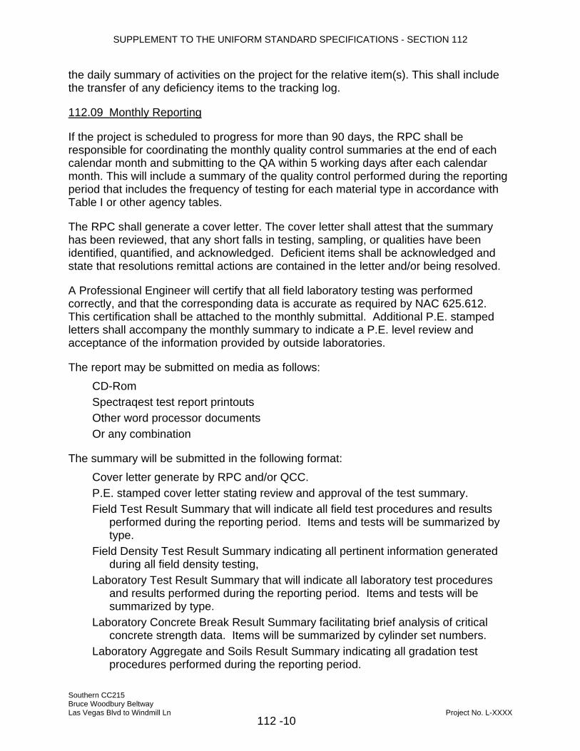
SUPPLEMENT TO THE UNIFORM STANDARD SPECIFICATIONS - SECTION 112
the daily summary of activities on the project for the relative item(s). This shall include the transfer of any deficiency items to the tracking log.
112.09 Monthly Reporting
If the project is scheduled to progress for more than 90 days, the RPC shall be responsible for coordinating the monthly quality control summaries at the end of each calendar month and submitting to the QA within 5 working days after each calendar month. This will include a summary of the quality control performed during the reporting period that includes the frequency of testing for each material type in accordance with Table I or other agency tables.
The RPC shall generate a cover letter. The cover letter shall attest that the summary has been reviewed, that any short falls in testing, sampling, or qualities have been identified, quantified, and acknowledged. Deficient items shall be acknowledged and state that resolutions remittal actions are contained in the letter and/or being resolved.
A Professional Engineer will certify that all field laboratory testing was performed correctly, and that the corresponding data is accurate as required by NAC 625.612. This certification shall be attached to the monthly submittal. Additional P.E. stamped letters shall accompany the monthly summary to indicate a P.E. level review and acceptance of the information provided by outside laboratories.
The report may be submitted on media as follows: CD-Rom Spectraqest test report printouts Other word processor documents Or any combination
The summary will be submitted in the following format: Cover letter generate by RPC and/or QCC. P.E. stamped cover letter stating review and approval of the test summary. Field Test Result Summary that will indicate all field test procedures and results performed during the reporting period. Items and tests will be summarized by type. Field Density Test Result Summary indicating all pertinent information generated during all field density testing, Laboratory Test Result Summary that will indicate all laboratory test procedures and results performed during the reporting period. Items and tests will be summarized by type. Laboratory Concrete Break Result Summary facilitating brief analysis of critical concrete strength data. Items will be summarized by cylinder set numbers. Laboratory Aggregate and Soils Result Summary indicating all gradation test procedures performed during the reporting period.
Southern CC215 Bruce Woodbury Beltway Las Vegas Blvd to Windmill Ln Project No. L-XXXX
112 -10
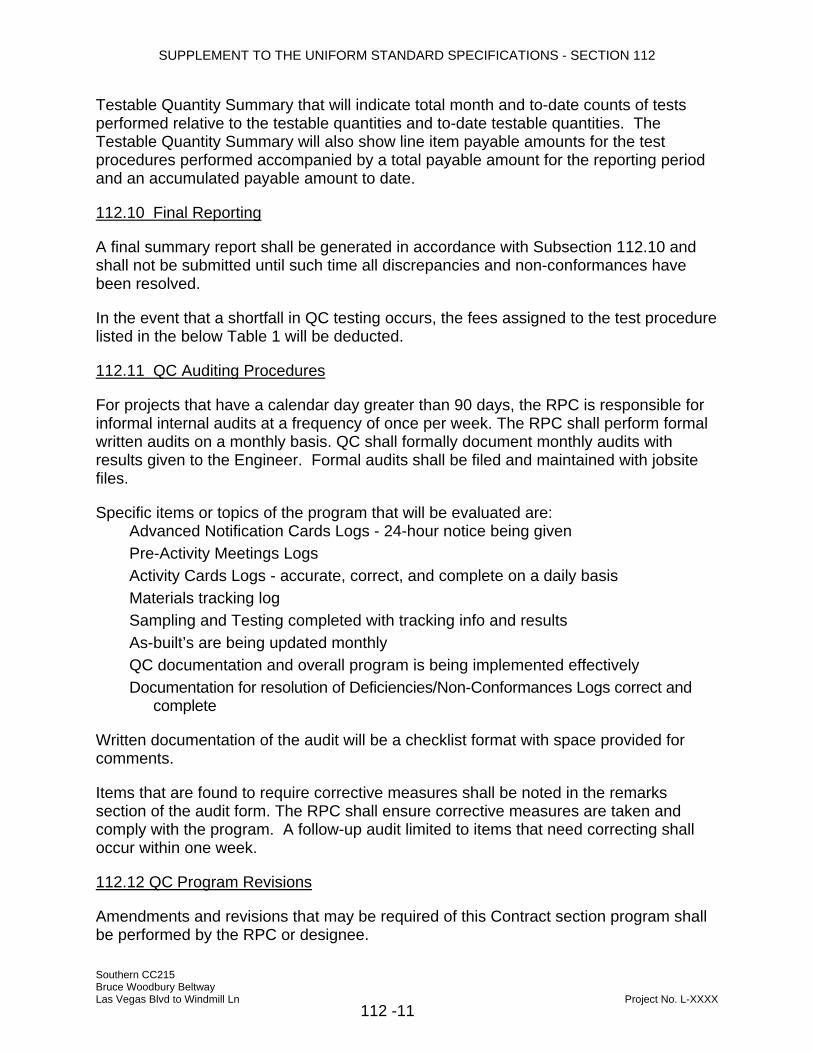
SUPPLEMENT TO THE UNIFORM STANDARD SPECIFICATIONS - SECTION 112
Testable Quantity Summary that will indicate total month and to-date counts of tests performed relative to the testable quantities and to-date testable quantities. The Testable Quantity Summary will also show line item payable amounts for the test procedures performed accompanied by a total payable amount for the reporting period and an accumulated payable amount to date.
112.10 Final Reporting
A final summary report shall be generated in accordance with Subsection 112.10 and shall not be submitted until such time all discrepancies and non-conformances have been resolved.
In the event that a shortfall in QC testing occurs, the fees assigned to the test procedure listed in the below Table 1 will be deducted.
112.11 QC Auditing Procedures
For projects that have a calendar day greater than 90 days, the RPC is responsible for informal internal audits at a frequency of once per week. The RPC shall perform formal written audits on a monthly basis. QC shall formally document monthly audits with results given to the Engineer. Formal audits shall be filed and maintained with jobsite files.
Specific items or topics of the program that will be evaluated are: Advanced Notification Cards Logs - 24-hour notice being given Pre-Activity Meetings Logs Activity Cards Logs - accurate, correct, and complete on a daily basis Materials tracking log Sampling and Testing completed with tracking info and results As-built’s are being updated monthly QC documentation and overall program is being implemented effectively Documentation for resolution of Deficiencies/Non-Conformances Logs correct and complete
Written documentation of the audit will be a checklist format with space provided for comments.
Items that are found to require corrective measures shall be noted in the remarks section of the audit form. The RPC shall ensure corrective measures are taken and comply with the program. A follow-up audit limited to items that need correcting shall occur within one week.
112.12 QC Program Revisions
Amendments and revisions that may be required of this Contract section program shall be performed by the RPC or designee.
Southern CC215 Bruce Woodbury Beltway Las Vegas Blvd to Windmill Ln Project No. L-XXXX
112 -11
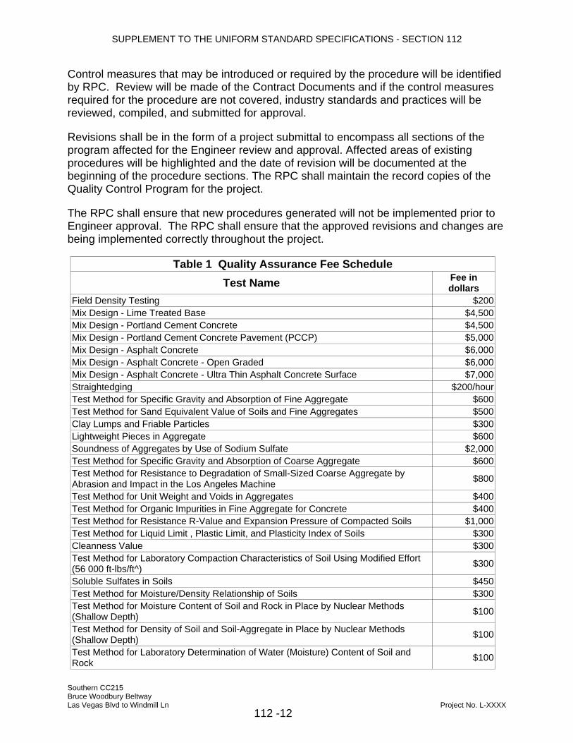
SUPPLEMENT TO THE UNIFORM STANDARD SPECIFICATIONS - SECTION 112
Control measures that may be introduced or required by the procedure will be identified by RPC. Review will be made of the Contract Documents and if the control measures required for the procedure are not covered, industry standards and practices will be reviewed, compiled, and submitted for approval.
Revisions shall be in the form of a project submittal to encompass all sections of the program affected for the Engineer review and approval. Affected areas of existing procedures will be highlighted and the date of revision will be documented at the beginning of the procedure sections. The RPC shall maintain the record copies of the Quality Control Program for the project.
The RPC shall ensure that new procedures generated will not be implemented prior to Engineer approval. The RPC shall ensure that the approved revisions and changes are being implemented correctly throughout the project.
Table 1 Quality Assurance Fee Schedule Test Name Fee in
dollars Field Density Testing $200Mix Design - Lime Treated Base $4,500Mix Design - Portland Cement Concrete $4,500Mix Design - Portland Cement Concrete Pavement (PCCP) $5,000Mix Design - Asphalt Concrete $6,000Mix Design - Asphalt Concrete - Open Graded $6,000Mix Design - Asphalt Concrete - Ultra Thin Asphalt Concrete Surface $7,000Straightedging $200/hourTest Method for Specific Gravity and Absorption of Fine Aggregate $600Test Method for Sand Equivalent Value of Soils and Fine Aggregates $500Clay Lumps and Friable Particles $300Lightweight Pieces in Aggregate $600Soundness of Aggregates by Use of Sodium Sulfate $2,000Test Method for Specific Gravity and Absorption of Coarse Aggregate $600Test Method for Resistance to Degradation of Small-Sized Coarse Aggregate by Abrasion and Impact in the Los Angeles Machine $800
Test Method for Unit Weight and Voids in Aggregates $400Test Method for Organic Impurities in Fine Aggregate for Concrete $400Test Method for Resistance R-Value and Expansion Pressure of Compacted Soils $1,000Test Method for Liquid Limit , Plastic Limit, and Plasticity Index of Soils $300Cleanness Value $300Test Method for Laboratory Compaction Characteristics of Soil Using Modified Effort (56 000 ft-lbs/ft^) $300
Soluble Sulfates in Soils $450Test Method for Moisture/Density Relationship of Soils $300Test Method for Moisture Content of Soil and Rock in Place by Nuclear Methods (Shallow Depth) $100
Test Method for Density of Soil and Soil-Aggregate in Place by Nuclear Methods (Shallow Depth) $100
Test Method for Laboratory Determination of Water (Moisture) Content of Soil and Rock $100
Southern CC215 Bruce Woodbury Beltway Las Vegas Blvd to Windmill Ln Project No. L-XXXX
112 -12

SUPPLEMENT TO THE UNIFORM STANDARD SPECIFICATIONS - SECTION 112
Test Method for Density and Unit Weight of Soils in Place by the Sand-Cone Method $300Test Method for Material Finer Than the 75-um (No.200) Sieve in Mineral Aggregate by Washing $100
Test Method for Sieve Analysis of Fine and Coarse Aggregates $250Ph and Electrical Resistance $100Solubility of Soils $100Test Method for Preparation and Testing of Soil-Cement Slurry Test Cylinders $200/setTest Method for Compressive Strength of Molded Soil-Cement Cylinders $50Test Method for Flat and Elongated Particles in Coarse Aggregates $300Test Method for Lime Content of Uncured Soil-Lime Mixtures $250Method of Test for Determining Percent of Fractured Faces $200Method of Test for Viscosity of Polymer Modified Asphalts By Vacuum Capillary Viscometer $250
Method of Test for Toughness and Tenacity of Polymer Modified Asphalt $250Method of Test for Ductility of Bituminous Materials $250Test Method for Flash Point and Fire Points of Liquids by Tag Open-Cup Apparatus $200Test Method for Solubility of Asphalt Materials in Trichloroethylene $200Viscosity of Asphalts by Vacuum Capillary Viscometer $250Test Method for Penetration of Bituminous Materials $150Test Method for Ductility of Bituminous Materials $250Test Method for Water in Petroleum Products and Bituminous Materials by Distillation $300Test Method for Emulsified Asphalts $600Test Method for Saybolt Viscosity $250Test Method for Distillation of Cut-Back Asphaltic (Bituminous) Products $600Flash Point with Tag Open-Cup Apparatus For Use with Material Having a Flash Less Than 93.3C (200F) $200
Test Method for Quantitative Extraction of Bitumen from Bituminous Paving Mixtures $300Method of Determining Moisture Content of Asphalt Mixtures or Mineral Filler Aggregate using Microwave Ovens $100
Determining the Asphalt Content of Hot Mix Asphalt (HMA) by Ignition Method $250Test Method for Asphalt Content of Bituminous Mixtures by the Nuclear Method $250Test Method for Resistance to Plastic Flow of Bituminous Mixtures Using Marshall Apparatus $300/set
Test Method for Moisture or Volatile Distillates in Bituminous Paving Mixtures $150Resistance of Compacted Bituminous Mixture to Moisture Induced Damage $650/setTest Method for Theoretical Maximum Specific Gravity and Density of Bituminous Paving Mixtures $200
Test Method for Density of Bituminous Concrete in Place by Nuclear Method $50/testPractice for Bituminous Mixing Plant Inspection $100/hourTest Method for Bulk Specific Gravity and Density of Compacted Bituminous Mixtures Using Paraffin-Coated Specimens $125/set
Test Method for Flash Point and Fire Point by Cleveland Open Cup $200Test Method for Specific Gravity and Density of Semi-Solid Bituminous Materials $300Test Method for Effect of Heat and Air on Moving Film of Asphalt (Rolling Thin-Film Oven Test) $700
Test Method for Kinematic Viscosity of Asphalt $250RTFO Residue - Test Method for Kinematic Viscosity of Asphalt @ 140 $250RTFO Residue - Test Method for Ductility of Bituminous Materials @ 45ºF $200RTFO Residue - Test Method for Ductility of Bituminous Materials @ 77ºF $200RTFO Residue - Test Method for Penetration of Bituminous Materials @ 77ºF $200
Southern CC215 Bruce Woodbury Beltway Las Vegas Blvd to Windmill Ln Project No. L-XXXX
112 -13

SUPPLEMENT TO THE UNIFORM STANDARD SPECIFICATIONS - SECTION 112
PAV Aged - Method for Determining Flexural Creep Stiffness of Asphalt Binder Using the Bending Beam Rheometer (BBR) $1,000
PAV Aged - Direct Tension $1,000Method for Determining the Rheological Properties of Asphalt Binder Using a Dynamic Shear Rheometer (DSR) $1,000
RTFO Residue - Method for Determining the Rheological Properties of Asphalt Binder Using a Dynamic Shear Rheometer (DSR) $1,000
PAV Aged - Method for Determining the Rheological Properties of Asphalt Binder Using a Dynamic Shear Rheometer (DSR) $1,000
Effect of Heat and Air on Asphalt Materials {Thin-Film Oven Test} $700Practice for Accelerated Aging of Asphalt Binder Using a Pressurized Aging Vessel (PAV) $1,000
Test Method for Viscosity Determinations of Unfilled Asphalts Using the Brookfield Thermosel Apparatus $1,000
Distillation Residue - Test Method for Penetration of Bituminous Materials @ 77ºF $600Distillation Residue - Test Method for Ductility of Bituminous Materials @ 77ºF $600Distillation Residue - Test Method for Solubility of Asphalt Materials in Trichloroethylene $600
Distillation Residue - Test Method for Kinematic Viscosity of Asphalt $600Test Methods for Sampling and Testing Fly Ash or Natural Pozzolans for Use as a Mineral Admixture in Portland-Cement Concrete $1,800
Test Method for Resistance of Dried Films of Varnishes to Water and Alkali $1,000Test Methods for Chemical Analysis of Hydraulic Cement $2,000Test Method for Effect of Organic Impurities in Fine Aggregate on Strength of Mortar $5,000Test Method for Air Content of Freshly Mixed Concrete by the Pressure Method $500Test Method for Resistance of Concrete to Rapid Freezing and Thawing $5,000Test Method for Obtaining and Testing Drilled Cores and Sawed Beams of Concrete $100/hourTest Method for Unit Weight of Structural Lightweight Concrete $300Test Method for Air Content of Freshly Mixed Concrete by the Volumetric Method $500Test Method for Slump of Hydraulic Cement Concrete $200Test Method for Unit Weight, Yield, and Air Content (Gravimetric) of Concrete $300Test Method for Compressive Strength of Cylindrical Concrete Specimens $500/set of 4Pumpability of Grout $400Test Methods for Making and Curing Concrete Test Specimens in the Field $200/hourTest Methods for Making and Curing Concrete Test Specimens in the Laboratory $200/hourQuality of Water to be Used in Concrete $500Concrete Plant Inspection $100/hourPaint Thickness $50Test Method for Nondestructive Measurement of Dry Film Thickness of Nonconductive Coatings Applied to a Nonferrous Metal $50
Test Method for Rubber Property - Durometer Hardness $300Test Method for Rubber Properties - Compression Set $300Test Method for Vulcanized Rubber and Thermoplastic Rubbers and Thermoplastic Elastometers - Tension $300
Test Method for Rubber Property - Adhesion to Rigid Substrates $300Test Method for Rubber Deterioration by Heat and Oxygen $300Test Method for Rubber - Deterioration in an Air Oven $300Specification for Fabricated Deformed steel Bar Mats for Concrete Reinforcement $200/barSpecification for Steel Welded Wire, Fabric, Plain, for Concrete Reinforcement $200/barTest Methods and Definitions for Mechanical Testing of Steel Products $200/bar
Southern CC215 Bruce Woodbury Beltway Las Vegas Blvd to Windmill Ln Project No. L-XXXX
112 -14
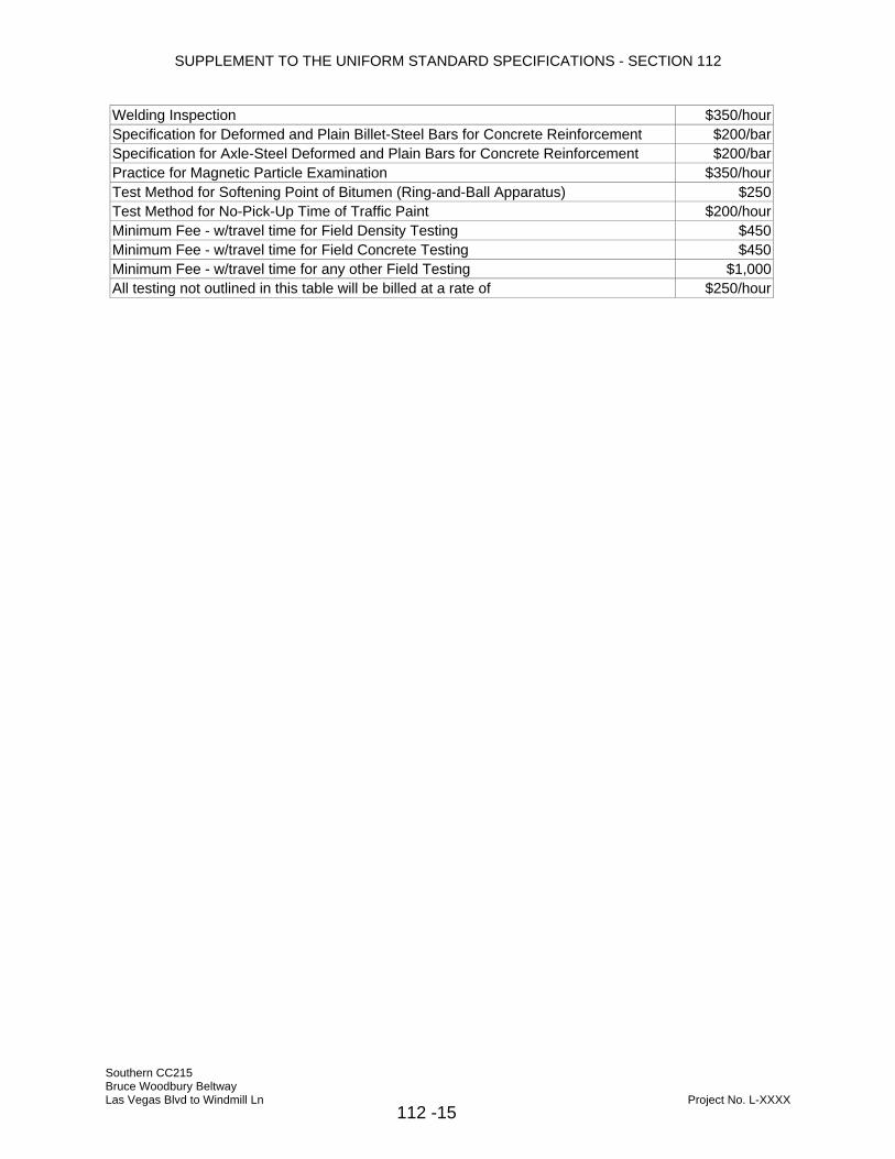
SUPPLEMENT TO THE UNIFORM STANDARD SPECIFICATIONS - SECTION 112
Welding Inspection $350/hourSpecification for Deformed and Plain Billet-Steel Bars for Concrete Reinforcement $200/barSpecification for Axle-Steel Deformed and Plain Bars for Concrete Reinforcement $200/barPractice for Magnetic Particle Examination $350/hourTest Method for Softening Point of Bitumen (Ring-and-Ball Apparatus) $250Test Method for No-Pick-Up Time of Traffic Paint $200/hourMinimum Fee - w/travel time for Field Density Testing $450Minimum Fee - w/travel time for Field Concrete Testing $450Minimum Fee - w/travel time for any other Field Testing $1,000All testing not outlined in this table will be billed at a rate of $250/hour
Southern CC215 Bruce Woodbury Beltway Las Vegas Blvd to Windmill Ln Project No. L-XXXX
112 -15

SUPPLEMENT TO THE UNIFORM STANDARD SPECIFICATIONS - SECTION 113
SECTION 113 QC ORGANIZATION AND QUALIFICATION OF INSPECTORS, LABORATORIES AND
TECHNICIANS 113.01 General
This section describes the minimum Contractor Quality Control Organization indicating chain of command and position descriptions. The information shall be submitted to the Engineer and approved prior to the beginning of the work.
The Contractor quality control material sampling shall be obtained from the Contractor's quality control technician. It shall not be given to the Contractor from a subcontractor or material supplier unless the Contractor NAQTC technician observes and documents the sampling.
The inspector may be the foreman or member of the crew.
The Qualifications, Scope of Work and Responsibilities, Communication, and Reporting for each position are related to the execution of the Project Quality Control Program only. Other roles, responsibilities, and reporting requirements may be required by the Engineer in the Contract specification. This Program does not address those roles or responsibilities, nor is it intended to diminish their intent.
The exceptions to this section are listed in Section 111, "Contractor Quality Control Administration - General."
113.02 Organization Chart
The minimum chain of command positions are as indicated in Figure 113.01 and titled as follows:
Position 1 - Contractor Principal Representative Position 2 - Professional Engineer (PE) Position 3 - Responsible Person-in-Charge (RPC) Position 4 - Quality Control Coordinator (QCC), may be performed by a RPC Position 5 - Quality Control Inspector (QCI) Positions 6 and 7 - Quality Control Technician (QCT) Positions 5, 6, and 7 may be the same person
Southern CC215 Bruce Woodbury Beltway Las Vegas Blvd to Windmill Ln Project No. L-XXXX
113-1

SUPPLEMENT TO THE UNIFORM STANDARD SPECIFICATIONS - SECTION 113
Quality Control (QC)
Prof Engineer Position 1.02
Principal Representative Position 1.01
Quality Control
Administrator Position 1.05
Responsible Person
in Charge (RPC) Position 1.03
QC Field/Lab
Testing Technician
Position 1.06/07
QC Inspector/Foreman
Position 1.04
Figure 113.1 Organization Chain of Command Suggested formats for providing the information to submit to the Engineer are shown in Tables 1 through 7 later in this section, which reference the typical organization as displayed in Figure 113.1.
Qualifications and experience requirements are provided for each QC position. The minimum experience requirements for selected positions are as follows:
The Responsible Person-in-Charge (RPC) shall have a minimum of 8 years' experience in construction managing the type of construction implemented on the Contract. The RPC shall have the ability to speak and read English and read and understand construction Drawings and Specifications. The RPC shall have stop work authority.
For the testing QC Laboratory, the Professional Engineer who is in responsible charge of the testing shall be a Nevada State licensed Civil Professional Engineer, with a minimum of 5 years' experience in construction materials. The field testing technicians shall be NAQTC and/or ACI Concrete Field Technician grade I certified and the Laboratory testing technician shall be NAQTC and/or ACI Concrete Laboratory Testing Technician Level 1 certified. All shall have the ability to speak and read English and read and understand construction Drawings and Specifications.
The Quality Control Coordinator (QCC) is a quality control administrator that ensures that the documents are coordinated to all levels of the project with a minimum of two (2) years experience in this type of work. The QCC shall have the ability to speak and read English and read and understand construction Drawings and Specifications.
The inspectors, or a foreman if used, shall have a minimum of 3 years of experience in the inspection of the particular type of construction work they are performing. The inspectors shall have the ability to speak and read English and read and understand construction Drawings and Specifications.
Southern CC215 Bruce Woodbury Beltway Las Vegas Blvd to Windmill Ln Project No. L-XXXX
113-2

SUPPLEMENT TO THE UNIFORM STANDARD SPECIFICATIONS - SECTION 113
Resumes of all RPC, QCC, PE, inspection, and material testing personnel shall be submitted.
The Contractor shall verify that qualifications of each employee match those required by the position that individual will hold and will be valid for the duration of the project. If personnel will require recertification during the Contract duration, the Contractor shall indicate those personnel and the process for ensuring that the recertification is accomplished.
The Contractor shall complete the Position Description Form (Tables 1 through 7) for each position including Name, Signature, Discipline, Employer, Stop-Work Authority, Certifications, and Title as applicable and submit to the Engineer for approval. Work shall not proceed until approved by the Engineer. One form will be used per position per individual. The form will include all disciplines of work and the related certifications for which the individual is qualified.
The inspection and testing staff utilized for a specific item of work may be comprised of any individual that has demonstrated competence and completed the appropriate form. Only QC Inspectors, technicians, or foreman with appropriate certifications will be used for that item of work.
When multiple QC Inspectors are used for a common work item, the individuals allowed to inspect a specific item within the work will be identified during the Pre-Activity Meeting. However, all personnel shall be approved by the Engineer.
113.03 Laboratories
For laboratories with multiple facilities, the Contractor shall identify the location of the lab providing the service. This table is project specific for the actual work that will be performed.
Separate laboratories may be used in conjunction with the Primary QC Laboratory. Prior to their use, the Contractor shall provide a submittal for each QC Laboratory. The approved submittal will then be added to QC program as an amendment.
With the exception of “chemical testing” (i.e. binder, cement), QC Laboratory reviewing personnel are required to be in responsible charge Professional Engineers, registered in the State of Nevada, regardless of whether the QC Laboratory utilized is primary or secondary.
Southern CC215 Bruce Woodbury Beltway Las Vegas Blvd to Windmill Ln Project No. L-XXXX
113-3

SUPPLEMENT TO THE UNIFORM STANDARD SPECIFICATIONS - SECTION 113
Table 1 - Contractor Principal Representative
Position Number Position Title Stop-Work Authority
1.01 Contractor Principal Representative Yes
Name: 1 Scope of Work and Responsibilities:
Perform corporate oversight for the Quality Control. Determine course of action for Quality Control at highest level of Conflict Resolution process. Quality Control related issues within the Organization.
2 Communication - Provide direct access for the following individuals:
RPC Quality Control Coordinator Professional Engineer Communication protocol:
To Whom What When CCPW QC Conflicts Resolve within One Week
3
QC Professional Engineer After QC Resolutions 1 Day
Southern CC215 Bruce Woodbury Beltway Las Vegas Blvd to Windmill Ln Project No. L-XXXX
113-4

SUPPLEMENT TO THE UNIFORM STANDARD SPECIFICATIONS - SECTION 113
Table 2 - Quality Control Professional Engineer
Position Number Position Title Stop-Work Authority
1.02 Quality Control Professional Engineer Yes
Name: 1 Scope of Work and Responsibilities:
In responsible charge over Quality Control Testing, both field and laboratory testing. Signature for all testing reports. Liaison for the Prime Contractor for Materials and testing related issues. Provide consultation to Prime Contractor as requested. Aid in providing resolution in material deficiencies.
2 Maintain open and effective communication with the following individual on a twice weekly basis:
RPC 3 Maintain open and effective communication and testing oversight with the following
individuals on a daily basis:
Testing Technician (Field & Lab) Source / Plant Inspector (when an employee of Engineer)
4 Have direct access to the following individual: Principal Representative Communication protocol:
To Whom What When RPC QC Conflicts - Investigation Resolve Within 1 day of Test
Completion or 3 days for other material issues
Monthly Report of Field and Lab Results
At time of Pay Estimate
Final Report of Field and Lab Results Within 2 weeks from “Substantial Completion”
RPC or designee
Deficiencies in Lab Test Results Immediately upon completion of testing
5
QC Technician After Resolution 1 hour
Southern CC215 Bruce Woodbury Beltway Las Vegas Blvd to Windmill Ln Project No. L-XXXX
113-5

SUPPLEMENT TO THE UNIFORM STANDARD SPECIFICATIONS - SECTION 113
Table 3 - Responsible Person in Charge (RPC)
Position Number Position Title Stop-Work Authority
1.03 Responsible Person in Charge (RPC) Yes
Name: 1 Scope of Work and Responsibilities:
Expedite Conflict Resolution. Educate Lead / Foreman of responsibilities to the QC Program. Generate or advise QC coordinator to review and forward Materials Submittals. Measurement and reporting of daily quantities.
2 Maintain open and effective communication and testing oversight with the following individual on a daily basis:
Principal Representative 3 Have direct access to the following individual:
Principal Representative 4 Communication - Provide direct access for the following individual:
Quality Control Inspector Communication protocol:
To Whom What When RPC QC Conflicts - Investigation Resolve within 1 day
5
Inspector/Foreman Materials Delivery and Quantities Log Daily
Southern CC215 Bruce Woodbury Beltway Las Vegas Blvd to Windmill Ln Project No. L-XXXX
113-6

SUPPLEMENT TO THE UNIFORM STANDARD SPECIFICATIONS - SECTION 113
Table 4 - Quality Control Coordinator (QCC)
Position Number Position Title Stop-Work Authority
1.04 Quality Control Coordinator (QCC) Contractor Option
Name: 1 Scope of Work and Responsibilities:
Dispatch Inspectors and Testers. Generate, close, and maintain file system for Activity Cards. Generate, close, and maintain file system for Advance Notification Cards. Generate, track, and maintain all Logs. Perform the Administration for all Quality Control documentation. Perform routine audits of Quality Control and documentation. Review materials submittals for compliance with Contract Documents. Receive, Log, and Schedule sampling of Materials Delivery and Quantities
2 Maintain open and effective communication with the following individuals on a twice weekly basis at a minimum:
Professional Engineer 3 Maintain open and effective communication and testing oversight with the following
individuals on a daily basis:
RPC QC Inspectors Testing Technicians
4 Have direct access to the following individuals:
Principal Representative Quality Assurance Coordinator
5 Communication - Provide direct access for the following individuals:
Quality Control Inspector Quality Control Technician Communication protocol:
To Whom What When Activity Card Close-out Daily Advanced Notification Cards Prior to Days Work Generation of Activity Card Daily Deficiencies Immediately Materials Delivery Log Daily Sample Log and Scheduling of Samples for Materials Delivered
Daily
Deficiency Log Daily Monthly QC Reports With Monthly Pay Estimate Final QC Report End of Construction
QA Inspector / Inspector
QC Resolutions 1 Hour Activity Cards Prior to Days Work QC Conflicts Resolve within 2 Hours
6
RPC
QC Resolutions 1 Hour
Southern CC215 Bruce Woodbury Beltway Las Vegas Blvd to Windmill Ln Project No. L-XXXX
113-7

SUPPLEMENT TO THE UNIFORM STANDARD SPECIFICATIONS - SECTION 113
Table 5 - Quality Control Contract or Material Source Inspectors
Position Number Position Title Stop-Work Authority
1.05
Quality Control Contract or Material Source Inspectors Yes
Name: 1 Scope of Work and Responsibilities:
Perform inspections and possibly testing. However, if testing, shall comply with NAQTC field test module. Review materials Testing Technician test results. Ascertain work compliance to Contract Documents. Responsible for Quality Control acceptance of work. Responsible for identifying deficient or Non-Compliant work. Will execute “stop work” authority when work or materials are found to be deficient and/or Non-Compliant. Responsible for identifying deficient or Non-Compliant work. Signature for Activity Card Inspection Section items. Measurement, Calculation, and reporting of Testable Quantities. Report deficiencies.
2 Maintain open and effective communication and testing oversight with the following individuals on a daily basis:
RPC Professional Engineer Testing Technician Source / Plant Inspector QA Inspector
3 Have direct access to the following individuals:
RPC Quality Control Coordinator and/or RPC
4 Communication - Provide direct access for the following individual(s):
Quality Control Technician Communication protocol:
To Whom What When Inspection Results Immediately Testable Quantities Immediately QC Conflicts Immediately
QA Inspector
Deficiencies Immediately Upon Scheduled InspectionRPC Activity Card With Test Results attached at the end of
the event. Will be completed by the end of the day.
5
Quality Control Coordinator and/or RPC
QC Conflicts 2 Hours
Southern CC215 Bruce Woodbury Beltway Las Vegas Blvd to Windmill Ln Project No. L-XXXX
113-8

SUPPLEMENT TO THE UNIFORM STANDARD SPECIFICATIONS - SECTION 113
Table 6 - Quality Control Field Testing Technician
Position Number Position Title Stop-Work Authority
1.06 Quality Control Field Testing Technician Contractor Option
Name: 1 Scope of Work and Responsibilities:
This individual is the “support” for the Quality Control Inspector. Verifies conformance of materials through testing. Advisor to Quality Control Inspector in regard to testing. Responsible for accurately testing, sampling, and reporting of results for construction materials. Responsible for identifying deficient or Non-compliant work, as related to testing. Responsible for notifying Quality Control and Quality Assurance of status of work, as related to testing.
2 Maintain open and effective communication and testing oversight with the following individuals on a daily basis:
RPC Professional Engineer Quality Assurance Coordinator Inspector
3 Have direct access to the following individual:
Quality Assurance Coordinator 4 Communication - Provide direct access for the following individuals:
Quality Control Inspector Quality Control Lab Technician Communication protocol:
To Whom What When Test results Immediately Deficiencies Immediately Upon Failing Test or
Observation
QC/QA Inspector/Foreman
Informational Testing Before performing informational tests
5
RPC Test Results Attach to Activity Card at the end of the Event.
Southern CC215 Bruce Woodbury Beltway Las Vegas Blvd to Windmill Ln Project No. L-XXXX
113-9

SUPPLEMENT TO THE UNIFORM STANDARD SPECIFICATIONS - SECTION 113
Table 7 - Quality Control Laboratory Testing Technician
Position Number Position Title Stop-Work Authority
1.07 Quality Control Laboratory Testing Technician Contractor Option
Name: 1 Scope of Work and Responsibilities:
This individual is the “support” for the Professional Engineer. Verifies conformance of materials and work through testing. Advisor to Quality Control Inspector in regard to testing. Responsible for accurately testing, sampling, and reporting of results for construction materials. Responsible for identifying deficient or Non-compliant work, as related to testing. Responsible for notifying Quality Control and Quality Assurance of status of work, as related to testing.
2 Maintain open and effective communication and testing oversight with the following individuals on a daily basis:
Quality Control Coordinator Professional Engineer
3 Have direct access to the following individual:
Quality Assurance Coordinator 4 Communication - Provide direct access for the following individual:
Quality Control Inspector Communication protocol:
To Whom What When Professional Engineer
Test results Immediately
5
Professional Engineer
Deficiencies Immediately Upon Failing Test or Observation
Southern CC215 Bruce Woodbury Beltway Las Vegas Blvd to Windmill Ln Project No. L-XXXX
113-10

SUPPLEMENT TO THE UNIFORM STANDARD SPECIFICATIONS - SECTION 113
THIS PAGE INTENTIONALLY LEFT BLANK
Southern CC215 Bruce Woodbury Beltway Las Vegas Blvd to Windmill Ln Project No. L-XXXX
113-11
SUPPLEMENT TO THE UNIFORM STANDARD SPECIFICATIONS - SECTION 114
SECTION 114
QC INSPECTION PROCEDURES
114.01 General
The Inspector shall be qualified as required in Section 113, “QC Organization and Qualification of Inspectors, Technicians, and Laboratories,” or as stated in other Contract Documents.
These inspections and tests include, but are not limited to, qualification tests, factory fabrication and verification tests, material and pre-operational checks/tests, site construction, installation, and testing.
Inspection, process oversight, and testing of items under construction shall be performed for work activities as required in the Contract Documents and at the frequency referenced in the specifications.
A combination of inspection, testing and process oversight shall be performed in a systematic manner to ensure the specific requirements for control of the process and quality of the item are being achieved throughout the duration of the process.
Inspection, oversight, and test results shall be documented in accordance with the Quality Control Program requirements in Section 111 “Contractor Administration and Quality Control-General”. Inspection results shall be evaluated and the acceptance determined by the Engineer. Modifications, repairs or replacement of items subsequent to final inspection shall be re-inspected and/or retested to verify acceptance.
114.02 Section 114 Outline
114.03 Organization 114.04 Inspection Process
Pre-Activity Meetings Notification Cards Quality Control Activity Card Process Sampling and Testing Oversight Inspections Final Inspection(s) and Testing Hold Processes Material Sources Elevation References
114.05 Field Problem Identification and Reporting Process 114.06 Tracking Responsibility 114.07 Testing Identification Responsibility 114.08 Inspection Procedures
Southern CC215 Bruce Woodbury Beltway Las Vegas Blvd to Windmill Ln Project No. L-XXXX
114 - 1

SUPPLEMENT TO THE UNIFORM STANDARD SPECIFICATIONS - SECTION 114
114.09 Inspection Reports
114.03 Organization
The organization is based on Section 111, "Contractor Administration and Quality Control - General," that identifies the minimum levels for communication and delegation for the Quality Control program. 114.04 Inspection Process
The Contractor inspector(s) shall have the experience to observe, document, instruct, and in general ensure that the work is installed and ensure that all testing requirements have been met for the Contract Documents.
The Contractor's in-process inspection program shall utilize a 4-phase inspection plan outlined as follows:
114.04.01 Pre-Activity Meetings
For the first start-up of any bid of work or in the change of a crew for the same work, a meeting shall be conducted with all persons involved.
It is encouraged that the information outlined below be relayed during the daily course of the project and through any periodic progress meetings to reduce the number of time consuming meetings. However, formal Pre-Activity Meetings shall be held as activities begin for a period of unbroken time. It is intended that the Pre-Activity Meeting be held at the actual location of the work. The Pre-Activity Meeting shall be held as the first item of work on the shift that the actual work shall begin, or at the end of that crew’s previous shift. When working a multi-jurisdictional project such as with NDOT, 2 days' advance notice is required prior to the meeting being held.
The meetings shall be held to discuss all quality control and operational aspects of proposed activities. All activities may necessitate meetings, unless extenuating circumstances dictate the need for meetings on general and common activities.
The meetings may be held under special requests made by the Engineer and shall also be held in the event of major personnel changes with respect to the project such as project manager for the Engineer or the Contractor.
The RPC shall facilitate the meetings at the project level.
Due to scheduling and workload, the activity Foreman may not be available to attend Pre-Activity Meetings; however, every effort shall be made to accommodate this request. The RPC may serve in his place and shall consequently relay pertinent meeting information and conclusions to the Foreman prior to activity commencement. There shall be no minimum number of attendees required for Pre-Activity Meetings.
Southern CC215 Bruce Woodbury Beltway Las Vegas Blvd to Windmill Ln Project No. L-XXXX
114 - 2

SUPPLEMENT TO THE UNIFORM STANDARD SPECIFICATIONS - SECTION 114
Documentation of the meetings shall be provided by the RPC in the form of tape recordings and/or written documentation. A copy of the documentation (written and or recorded) shall be provided to the Engineer within 2 hours of the meeting.
The meetings shall accomplish the verification of the following items:
Description Ensure that all submittals are approved Review Plans, Specifications, and Procedures that apply List materials List any mandatory procedures (i.e., Manufacturers' specifications) Review Deficiencies in prior related work and note Verify that no outstanding deficiencies exist for work that led up to this activity Discussion of acceptance criteria Particular items of interest to the Engineer; QA’s expectations List of Control Measures and responsible parties, Review of Frequency of Control Measures Discussion of off-site and on-site QC responsibilities Discuss “What do we do when something goes wrong?” Traffic Control and Safety Issues and Notification to the Public Reminder that the public comes first Items requiring QC Itemize frequency of inspection and testing. Define any revision of Contract specification protocol and documentation revision approved by the Engineer
The following individuals are required to attend the Pre-Activity Meeting for work that they perform:
RPC QC Inspector QA Inspector Responsible activity foreman
114.04.02 Notification Cards
The Contractor shall utilize the Advance Notification Card in the example forms to schedule all Activities.
114.04.03 Quality Control Activity Card Process
QC Activity Cards, examples in Section 115, will not be required when activities do not necessitate testing or inspection to be performed on the item.
The RPC is responsible for verifying all documentation on the QC Activity and Notification Cards is in compliance with this program before being presented to the QA Representatives for “sign-off” and closeout of the activity.
Southern CC215 Bruce Woodbury Beltway Las Vegas Blvd to Windmill Ln Project No. L-XXXX
114 - 3

SUPPLEMENT TO THE UNIFORM STANDARD SPECIFICATIONS - SECTION 114
The inspection staff utilized for this project can be comprised of any of the personnel listed in this section with the stipulation that only personnel with appropriate field certifications shall be used. For type A projects, the RPC is responsible for inspections; however, there may be instances where the inspection and documentation thereof shall be delegated to the activity foreman by the RPC based on the technician’s workload and/or his or her certifications.
The project can typically employ a foreman for each area of work involved; however, there may be instances where several foremen shall be utilized for a particular area of work. There shall not be instances where foreman shall perform inspections on items in other areas of work unless the foreman is so qualified and proof of such is provided prior to inspections and subsequent activities based on those inspections.
The testing staff utilized for this project can be comprised of any of the personnel listed in this section with the stipulation that only technicians with appropriate certification shall be used.
The RPC shall use the following guidelines for QC Activity Card identification and logging:
QC Activity Cards shall be issued a sequential number to uniquely identify it with the activity.
QC Activity Cards generated and filed shall be logged on the QC Activity card Log as described in Section 112.
Activity Card Section 1 – Actual Work Performed Used to document the actual work performed for the activities listed. Locations shall be listed to correlate with the type of work performed.
Activity Card Section 2 – Deficiency Check Used for documenting existing deficiencies associated with the activity listed in Section 1. If no deficiencies exist or occur for the activity, the Inspector or Technician shall check-off and initial this section. If deficiencies do exist, the Inspector or Technician shall complete the lower area of this section. Each material number shall be verified against outstanding deficiencies.
Activity Card Section 3 – Item/Material for Inspection Used for documenting inspections associated with the activities listed in Section 1 and for documentation of QA verification inspections.
Each inspected material utilized during the activity shall be entered. The completion of the RPC next section “QC Initial/Date” shall serve as documentation of the quality control inspection performed. There shall be instances where the RPC fills out the QC Activity Card but does not initial the inspection. In these cases, the RPC shall require the particular activity Foreman, or subcontractor Foreman/Supervisor, to initial the
Southern CC215 Bruce Woodbury Beltway Las Vegas Blvd to Windmill Ln Project No. L-XXXX
114 - 4

SUPPLEMENT TO THE UNIFORM STANDARD SPECIFICATIONS - SECTION 114
inspection. Electrical items shall almost always be inspection initialed by the activity Foreman.
Inspections to be performed are listed in the QC Table 1 on website: http://www.accessclarkcounty.com/depts/public_works/Pages/qa.aspx
The next section “QA Initial/Date” shall be utilized for QA’s documentation of verification of the inspections listed within the section.
The RPC and/or Foreman shall give a maximum one-day advance notice to QA of verification inspections to be performed. If so notified and verification inspections cannot be performed by QA, subsequent activities may proceed and RPC or Foreman’s inspection of a particular item shall justify as permission to proceed with subsequent activities provided no exceptions were taken. If QA was unable to attend the inspection, a statement thereof shall be made on the QC Activity card. In the event a difference of opinion or interpretation of specifications occur between the RPC or Foreman and QA the conflict shall be resolved with every effort of both parties to resolve the issue at the lowest possible level.
The RPC or Foreman can initial inspection of an activity/item that he was not continuously present; however there shall be an acceptable level of periodic oversight performed in order to initial the inspection. .
The inspection observation reports shall be attached to the activity card.
Activity Card Section 4 – Testing and Sampling Requirements Used for documenting field tests associated with the activities listed in Section 1.
The RPC shall indicate the description of the test performed. The “Actual” column shall also be completed by RPC and shall reflect the actual number of tests performed for each item listed.
The final column, “Testable Quantity,” shall be completed by the RPC and shall indicate the amount of material that was available for testing for the items listed within this section. The amount shall be followed by the appropriate unit (square feet, cubic yard, linear feet). Calculations shall be shown to justify the number entered, for instance, when there may be multiple lifts of trench backfill tested and documented.
Activity Card Section 5 – Remarks Used for documentation of miscellaneous information associated with the activities listed on the card. This section shall also be used to document formulas used to calculate the number of tests required.
Southern CC215 Bruce Woodbury Beltway Las Vegas Blvd to Windmill Ln Project No. L-XXXX
114 - 5

SUPPLEMENT TO THE UNIFORM STANDARD SPECIFICATIONS - SECTION 114
Activity Card Section 6 – Quality Assurance Sign-Off Used for documentation of the QA sign-off of the QC work performed associated with the activity listed. Upon sign-off, a copy of the QC Activity Card with applicable test and inspection observation reports results shall be delivered to RPC.
114.04.04 Sampling And Testing
All sampling and testing shall be performed in accordance with the Table I at web site: http://www.accessclarkcounty.com/depts/public_works/Pages/qa.aspxor other Agency jurisdiction and the contract documents.
All density testing locations shall be clearly identified by paint marking on the grade at the time the testing is performed. All trench walls or structure shall have backfill lift thickness marked in paint. This requirement will aid in the correlation testing by Quality Assurance.
114.04.05 Oversight Inspections
The Contractor shall provide documented full time inspection during construction. In addition to daily inspection of the physical performance of the work, oversight shall include any combination of the following:
(a) Observation of Quality Control and Quality Assurance tests performed with narrative documentation of the observation;
(b) Review or spot check of procedures or instructions governing the work, including inspection and test procedures;
(c) Evaluation or verification of the presence and effectiveness of project controls; (d) Coordination with personnel performing or supervising the work; (e) Review all field and lab test data. Completed items shall be inspected for completeness, markings, calibration, adjustments, protection from damage, or other characteristics as required verifying the quality of workmanship and conformance of the item to specified requirements. Quality records, where required, shall be examined for adequacy and completeness and available for audit by the Engineer. A sample inspection document shall be submitted to the Engineer for each type of inspection item. The Contractor may use documents supplied by the Engineer.
114.04.06 Final Inspection(S) And Testing
Final inspection(s) and tests which are performed to demonstrate and verify functional operation and conformance to the Contract requirements of the products, subsystems and systems constructed, fabricated, manufactured, and installed by the Contractor or its subcontractors and suppliers for the Project in accordance with the Contract Documents.
Southern CC215 Bruce Woodbury Beltway Las Vegas Blvd to Windmill Ln Project No. L-XXXX
114 - 6

SUPPLEMENT TO THE UNIFORM STANDARD SPECIFICATIONS - SECTION 114
Prior to final inspection(s) and tests, a review of the deficiencies identified during the in-process inspections and tests shall be performed by the RPC to verify that corrective action has been completed, verified, and documented. The final inspection or test shall demonstrate the conformance of the item to specified requirements.
114.04.07 Hold Point Processes
A “hold point” is the point in the construction installation of one step that must await a previous step to be completed and approved by the Engineer to proceed. These hold points are defined in website: http://www.accessclarkcounty.com/depts/public_works/Pages/qa.aspxunder the section general heading or in other Contract Documents. A hold point not indicated in the Contract Documents may be defined by the Contractor and approved by the Engineer.
The Contractor shall not proceed without specific approval of the Engineer.
114.04.08 Material Sources
On-site delivery of material items furnished by suppliers to be incorporated into the work shall be jointly inspected upon receipt by the Contractor's Quality Control personnel and the Engineer to verify conformance to specified requirements. Source inspection of items fabricated or manufactured specifically for the Project shall be performed jointly as required by the Contract Documents.
The Engineer may conduct independent Quality Assurance and/or Independent Assurance (IA) inspection/testing and source inspections as deemed necessary. The Engineer or Engineer's representative shall coordinate these inspections and tests as required.
114.04.09 Elevation References
In order to aid in the overall coordination of testing and inspection location, use the below table of Elevation References.
Abbreviation Grade Name Description of Grade FG Finish Grade Final elevation for the top of the
completed work FGAB Finish Grade - Aggregate Base Final elevation for the top of
Aggregate Base FGE Finish Grade - Embankment Final elevation for the top of
Embankment Fills FGS Finish Grade - Subgrade Final elevation for the top of
Subgrade *Note 1
Southern CC215 Bruce Woodbury Beltway Las Vegas Blvd to Windmill Ln Project No. L-XXXX
114 - 7
SUPPLEMENT TO THE UNIFORM STANDARD SPECIFICATIONS - SECTION 114
Note 1: The Finish Grade - Subgrade elevation shall only reference the top of the “scarified and recompacted,” “in-place,” and "native” original ground material. This elevation shall not be used to reference any portion of embankment materials. In Trench Zone work, this elevation shall be the bottom of the trench excavation only; all other elevations shall be referenced to FGE, FGAB, or FG. In the event that the Aggregate Base Zone is placed directly on scarified original ground, the FGS elevation shall be used for the top of native Subgrade.
All elevations shall be “called out” as one of the Finish Grade elevations noted in the table above minus the number of feet below that grade.
An example would be Finish Grade Aggregate Base minus 0.5 feet or FGAB-0.5'. In the example, the elevation stated would be one/half of one foot below finish grade for the aggregate base.
Another example would be a trench backfill operation currently being tested 2 feet above a 3 feet thick pipe zone, in an 18 feet total depth trench measured from Finish Grade (FG) would be FG-13'. Alternately, if the pavement zone and aggregate base zone are not given for the work, the elevation may be FGE-13' for the same excavation where the surface elevation is Finish Grade Embankment.
When available for the Project, the actual elevation in feet North American Vertical Datum of 1988 (NAVD 88) shall be noted on all documentation in addition to the elevation “call out” above.
114.05 Field Problem Identification And Reporting Process
This procedure outlines the use procedure for identification and reporting of a deficiency.
(a) If a problem is observed by a Non-Quality Control Personnel: (1) Locate the QC Inspector. (2) Inform the QC Inspector of the Deficiency and any additional information details
special circumstance. (b) If a problem is observed by a Testing Technician:
(1) Your testing indicates deficient work: (a) Record all testing data. (b) Locate QC Inspector. (c) Provide detail of Deficiency to QC Inspector.
(2) You observed deficient work: (a) Locate QC Inspector. (b) Provide detail of Deficiency to QC Inspector.
Southern CC215 Bruce Woodbury Beltway Las Vegas Blvd to Windmill Ln Project No. L-XXXX
114 - 8

SUPPLEMENT TO THE UNIFORM STANDARD SPECIFICATIONS - SECTION 114
(c) If a problem is observed by a QC Inspector: (1) Gather information from anyone with knowledge of Deficiency. (2) Notify and discuss deficiency with QA Inspector to identify possible resolution. (3) Discuss Deficiency with QA Inspector to identify possible resolution. (4) QC to provide possible solution, QA agrees with proper solution. (5) If resolution cannot be achieved within that day, one of two courses of action
needs to be taken as follows: (a) If resolution can be achieved the following day:
(1) Verify that the resolution was performed and that all aspects of work are now in compliance with Contract Documents.
(2) If it is not in compliance, Notify QC immediately. (6) If work is now in compliance, note resolution in deficiency area of Activity Card,
with written description of resolution, making notes in remarks which detail the resolution process then: (a) Notify QA Inspector of Resolution. (b) Sign-off the Inspection Item.
(7) If resolution cannot be achieved the following day, note in the remarks any portion of the Activity Card that has a Deficiency pending.
114.06 Tracking Responsibility
The RPC shall be responsible for logging and tracking deficiencies on the QC Activity Card. Constant comparison against the deficiency log shall ensure no deficiency is left unresolved.
The RPC shall document deficiencies that are new or have been cleared for each item relative to each activity. Every effort shall be made to resolve deficiencies as soon as possible.
Section 2 of the QC Activity card is used for documenting existing deficiencies associated with the activity listed in Section 1 of the QC Activity card. If no deficiencies exist or occur for the activity the RPC shall check-off and initial this section. If deficiencies do exist, the lower area of this section shall be completed. Each material number shall be verified against outstanding deficiencies.
114.07 Testing Identification Responsibility
The RPC, utilizing the Table 1 at the website, shall identify the test methods, frequency of the tests, and the planned number of tests to be taken for each material used in the respective activity as explained in Section 112.
The planned number of tests to be taken shall be documented on the notification card. The actual number of tests taken on each material shall be documented by the RPC in Southern CC215 Bruce Woodbury Beltway Las Vegas Blvd to Windmill Ln Project No. L-XXXX
114 - 9
SUPPLEMENT TO THE UNIFORM STANDARD SPECIFICATIONS - SECTION 114
the appropriate space provided on the QC Activity Card. There may often be a large difference between the planned number of tests and actual number of tests taken. There may also be instances where a large number of planned tests were documented on the notification card and no actual tests were taken, given the probability of the cancellation of activities.
The testable quantity is the numerical amount of material actually available or “ready” for testing shown in units defined in Table I or related Agency testing of this program relative to the frequency of the material and based on the stationing information documented on the card. For example, the testable quantity of Type II grade for compaction from Station 0+00 to Station 10+00, given a width of 30 feet would be 30,000 square feet (SF). Given this example and using Table I, the minimum number of tests required for this item would be 6 total tests based on the required frequency of 1 test per 5,000 SF.
The RPC shall perform all necessary calculations to ensure the number of tests performed meet the required number. All minimum test numbers calculated shall be rounded up.
In the event that multiple lifts of material are represented or given that the testable quantity shown on the QC Activity Card is not readily identifiable with documented stations and dimensions, appropriate documentation and/or calculations shall be provided on the QC Activity Card to facilitate easy verification of the testable quantity. This process allows the technician to show documentation for the entire amount of material represented without documenting repetitive entries.
The RPC shall generally arrive at total quantities for each activity by documenting pertinent information such as stations, widths, and other miscellaneous dimensions at the beginning of the activity and comparing them against dimensions at the end of the activity. If situations arise where RPC cannot be present during all operations and would not be able to derive total quantities, the RPC shall retrieve the information from the activity Foreman. The Materials Tracking Logs shall also be utilized in this respect.
The QC Activity Cards shall reflect certain bid item payment quantities. However, the Contractor shall not use them for compilation of the monthly pay estimate or for bid item payment tracking. This is due to the difference between the pay item unit of measurement and the testable quantity unit of measurement shown in the QC table(s), and also given that payable activities may take place without the presence of a QC Activity Card. (No testing or Inspection.)
114.08 Inspection Procedures
The Contractor shall provide documented full time inspection during construction. In addition to daily inspection of the physical performance of the work, oversight shall include any combination of the following: (a) Observation of Quality Control and Quality Assurance tests performed with narrative
documentation of the observation Southern CC215 Bruce Woodbury Beltway Las Vegas Blvd to Windmill Ln Project No. L-XXXX
114 - 10
SUPPLEMENT TO THE UNIFORM STANDARD SPECIFICATIONS - SECTION 114
(b) Review or spot check of procedures or instructions governing the work, including inspection and test procedures;
(c) Evaluation or verification of the presence and effectiveness of project controls; (d) Coordination with personnel performing or supervising the work. (e) Review all field and lab test data
Completed items shall be inspected for completeness, markings, calibration, adjustments, protection from damage, or other characteristics as required verifying the quality of workmanship and conformance of the item to specified requirements. Quality records, where required, shall be examined for adequacy and completeness and available for audit by the Engineer. A sample inspection document shall be submitted to the Engineer for each type of inspection item. The Contractor may use documents supplied by the Engineer.
Each activity of work shall have a procedure approved by the Engineer that contains descriptions of the processes which address the requirements for inspections and tests for the particular crew activity. These must be submitted for approval prior to the pre-activity meeting. The minimum information per activity procedure shall include the following:
(1) Name of Crew Work (i.e. concrete curbs) (2) General Description of Work (3) Personnel Responsibilities (4) Checklists (5) Verification of Qualifications: Inspection, testing and oversight personnel who
verify conformance of work activities shall be qualified and/or certified as necessary to perform the assigned inspection/testing tasks.
(6) Responsible Individuals: The position name(s) or Title of the individual(s) with “stop work” authority shall be identified
(7) These inspections and tests include qualification tests, factory tests, installation and verification tests, material tests, and pre-operational checks/tests.
In addition to the standard forms, the inspector shall keep a written or electronic diary of activities. It shall contain such information as weather conditions, important conversations, visitors on the site, verbal orders received, unusual incidents, equipment breakdowns, length of work stoppages, number of persons and types of equipment affected by work stoppages, and any changes in the appearances of the material. Any item of significance shall be recorded. The importance of entries listed in the inspection’s diary cannot be over emphasized. The information is a reference that can be used to perform similar future work or in case of legal action. The Diary shall include as a minimum the following:
(1) Date including the year. (2) Weather conditions; cloudy, rain, etc.
Southern CC215 Bruce Woodbury Beltway Las Vegas Blvd to Windmill Ln Project No. L-XXXX
114 - 11

SUPPLEMENT TO THE UNIFORM STANDARD SPECIFICATIONS - SECTION 114
(3) Temperature – high and low (the web site wunderground.com is a good resource)
(4) Wind velocity and direction (approximate). (5) Contractor’s and Subcontractor’s working hours. (6) The work in progress. (7) Note any unusual situations encountered, such as accidents, damages to
vehicles or to the project, unusual material (bentonite, etc.), or anything that you would bring to the attention of others.
(8) Any instructions or suggestions from the Engineer. (9) Deviations and corrective action taken. (10) Changes to Plans. (11) Official visitors and their recommendations; official visitors may include FHWA,
Central Office Personnel, Region Personnel. (12) Project personnel. (13) Your signature and title.
Use a black pen to write in the Diary. Keep the diary up-to-date by placing all information directly in the diary. If you let it go, even for a short period of time or make notes on scratch paper, something of importance may be forgotten or lost.
Inspection results shall be evaluated and the acceptability determined by the Engineer.
114.09 Inspection Reports
The RCP shall review all inspection reports which shall contain enough detail to accurately describe the installation of the item. Industry standard checklists may be a part of this report but not a substitute.
Southern CC215 Bruce Woodbury Beltway Las Vegas Blvd to Windmill Ln Project No. L-XXXX
114 - 12

SUPPLEMENT TO THE UNIFORM STANDARD SPECIFICATIONS - SECTION 114
THIS PAGE INTENTIONALLY LEFT BLANK
Southern CC215 Bruce Woodbury Beltway Las Vegas Blvd to Windmill Ln Project No. L-XXXX
114 - 13
SUPPLEMENT TO THE UNIFORM STANDARD SPECIFICATIONS – SECTION 115
Southern CC215 Bruce Woodbury Beltway Las Vegas Blvd to Windmill Ln Project No. L-XXXX 115 - 1
SECTION 115 CONTRACTOR QUALITY CONTROL ADMINISTRATION AND INSPECTION FORMS
115.01 General
This section contains the document templates that shall be used by the Contractor for the Quality Control Program. If the Contractor would like to revise or use other documents in the quality control, they may be submitted to the Engineer for approval before use. Other example documents are located at the web site: http://www.accessclarkcounty.com/depts/public_works/Pages/qa.aspx
115.02 Section Content
The forms that are included are listed below:
(A) Advance Notification Card (B) Deficiency and Non-Conformance Log (C) Sample Tracking Log (D) Submittal Log (E) Pre-Activity Meeting Agenda (F) Materials Tracking Log (G) Bituminous Materials Tracking Log (H) Concrete Placement Log (I) QC Card (J) Document of Qualifications (K) Steel Certification (L) Asphalt Plant Inspection

SUPPLEMENT TO THE UNIFORM STANDARD SPECIFICATIONS – SECTION 115
Southern CC215 Bruce Woodbury Beltway Las Vegas Blvd to Windmill Ln Project No. L-XXXX
115-2
Project Name: Contractor: Bid Number: Date:
Advance Notification Card
Bid Item No. Brief Description of Work Activity Location Inspection Planned (X if Yes)
Type of Testing Planned
Amount of Testing Planned
Unexpected Activity Notification (Give Verbal Notification Immediately)

SUPPLEMENT TO THE UNIFORM STANDARD SPECIFICATIONS – SECTION 115
Southern CC215 Bruce Woodbury Beltway Las Vegas Blvd to Windmill Ln Project No. L-XXXX
115-3
BID NUMBER:
PROJECT: ___________________________ Verbal resolutions are not permitted. Page:
Deficiency Log ID Number
Reference QC Card Number
Date of Deficiency
QC & QA Initials
Reference QC Card Number
Date Corrected
QC & QA Initials
Deficiency and Non-Conformance Log
Originating Information Resolution Information
MaterialDescribe Deficiency/ Non-
Conformance Describe the Resolution

SUPPLEMENT TO THE UNIFORM STANDARD SPECIFICATIONS – SECTION 115
Southern CC215 Bruce Woodbury Beltway Las Vegas Blvd to Windmill Ln Project No. L-XXXX
115-4
Project Name: Bid Number: Contractor: SAMPLE TRACKING LOG
Original Sampling Information Reporting Information Disposition of Material
Partial Final
Sample Log ID
Number
Ref
eren
ce A
CTI
VITY
Lo
g ID
Num
ber
Date Sampled Material Type QC
Initials Date Initials Test
Results Reported
Date Initials
OK
(X
)
Faile
d (X
)
Mat
eria
l In
corp
orat
ed in
to
the
Wor
k (Y
es/N
o)
Ref
eren
ce D
efic
ienc
y Lo
g N
umbe
r

SUPPLEMENT TO THE UNIFORM STANDARD SPECIFICATIONS – SECTION 115
Southern CC215 Bruce Woodbury Beltway Las Vegas Blvd to Windmill Ln Project No. L-XXXX
115-5
Project Name: Bid Number: Contractor: SUBMITTAL LOG
ID N
umbe
r
Subm
ittal
N
umbe
r
Prev
ious
ID
Num
ber
Dat
e In
QC
Initi
als
RPC
App
rova
l D
ate
RPC
Sta
tus
Giv
en
Dat
e R
etur
ned
to S
ubm
itter
Dat
e Fo
rwar
ded
to
Age
ncy
Dat
e R
etur
ned
from
Age
ncy
Subm
ittal
St
atus
Trac
king
ID
Num
ber

SUPPLEMENT TO THE UNIFORM STANDARD SPECIFICATIONS – SECTION 115
Southern CC215 Bruce Woodbury Beltway Las Vegas Blvd to Windmill Ln Project No. L-XXXX 115 -6
Insert Project Name Here Bid Number 0000-00 Pre-Activity Meeting Agenda
Date Contract Day 0 of 0
Attendees Name Signature Initials Organization
Materials
Submittal Number Material Description Status and Exceptions
Mix Designs
Mix ID Type of Material Status and Exceptions
Outstanding Deficiency Check
Review of Plans and Spec Contract Plans UDACS
Special Provisions NDOT Standard Specs Other
Control Measures Type of Inspection/Testing Responsible Party's Name Frequency Traffic Control
General Item Inspections
Specific Inspections Specific Inspections Specific Inspections
Testing Testing Testing
PAGE 1 Extra Care Items
Name Material Type
Responsible Party
What to do if something goes wrong
Ways to maintain proper notification

SUPPLEMENT TO THE UNIFORM STANDARD SPECIFICATIONS – SECTION 115
Southern CC215 Bruce Woodbury Beltway Las Vegas Blvd to Windmill Ln Project No. L-XXXX
115-7
Project Name Bid Number Contractor:
MATERIALS TRACKING LOG Material Log ID
Number Date
Delivered Material Type Quantity Delivered
Certification / Ticket in Hand
(Yes/No)
Material Matches Submittal
Number (Y/N) QC Inspector
Initials
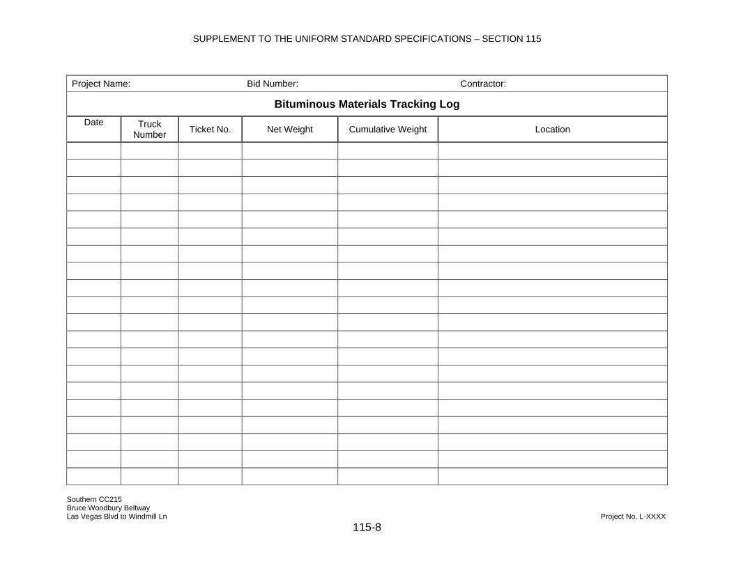
SUPPLEMENT TO THE UNIFORM STANDARD SPECIFICATIONS – SECTION 115
Southern CC215 Bruce Woodbury Beltway Las Vegas Blvd to Windmill Ln Project No. L-XXXX
115-8
Project Name: Bid Number: Contractor:
Bituminous Materials Tracking Log Date Truck
Number Ticket No. Net Weight Cumulative Weight Location

SUPPLEMENT TO THE UNIFORM STANDARD SPECIFICATIONS – SECTION 115
Southern CC215 Bruce Woodbury Beltway Las Vegas Blvd to Windmill Ln Project No. L-XXXX
115-9
Project Name: Bid Number: Contractor:
Concrete Placement Log
Mix Design Number:
Ticket No. Batch Time Time
Placement Complete
Total Time Concrete Temp
Unit Weight Slump Air
ContentWater
Added at Site
Cubic Yards
Page Total
Daily Total

SUPPLEMENT TO THE UNIFORM STANDARD SPECIFICATIONS – SECTION 115
Southern CC215 Bruce Woodbury Beltway Las Vegas Blvd to Windmill Ln
115-10
QC ACTIVITY CARD PROJECT: CONTRACT DAY: OF
Date: BID NO.: CARD NO.:
SECTION 1- ACTUAL WORK PERFORMED Type of Work Performed Location
SECTION 2 - DEFICIENCY CHECK No deficiencies exist or have occurred. QC Initials: Date:
QC has verified that deficiencies are outstanding and are listed by Item/Materials below:
Type of Deficiency/Description (use remarks for additional info) Deficiency Log ID # QC Initial & Date
SECTION 3 - INSPECTION ITEMS
The following items will be signed off by QC prior to the requested time for inspection by QA:
Material Description QC Initials/Date QA Initial / Date Time Requested for QA
SECTION 4 - TESTING & SAMPLING ITEMS
Item No. (Set A & B) Sequential Test Nos. Description of Test No.
Performed Testable Quantity
SECTION 5 - REMARKS
SECTION 6 - QA SIGN-OFF QA Representative Verification of QC Performance and Quantities Initials: Date:
This "sign-off' does not represent acceptance of work performed but is a verification that QC testing/inspection was performed and testable quantities are representative of the work.
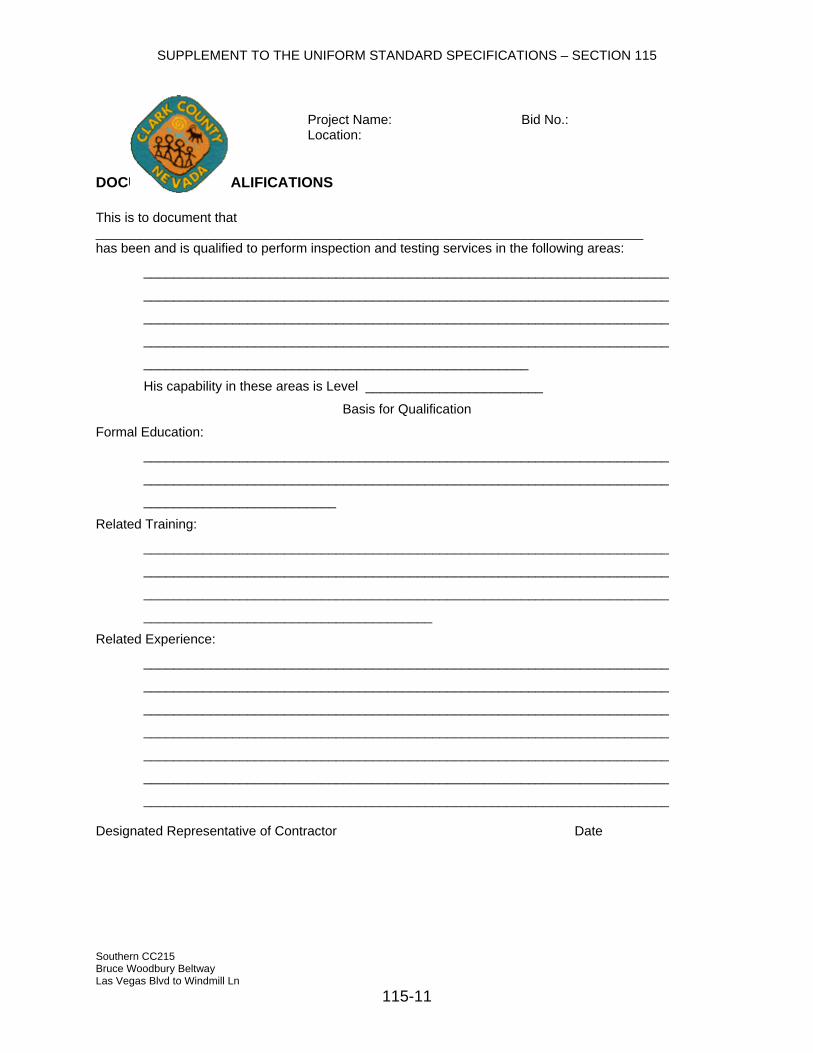
SUPPLEMENT TO THE UNIFORM STANDARD SPECIFICATIONS – SECTION 115
Southern CC215 Bruce Woodbury Beltway Las Vegas Blvd to Windmill Ln
115-11
Project Name: Bid No.: Location:
DOCUMENT OF QUALIFICATIONS This is to document that __________________________________________________________________________ has been and is qualified to perform inspection and testing services in the following areas:
_______________________________________________________________________
_______________________________________________________________________
_______________________________________________________________________
_______________________________________________________________________
____________________________________________________
His capability in these areas is Level ________________________
Basis for Qualification
Formal Education:
_______________________________________________________________________
_______________________________________________________________________
__________________________
Related Training:
_______________________________________________________________________
_______________________________________________________________________
_______________________________________________________________________
_______________________________________
Related Experience:
_______________________________________________________________________
_______________________________________________________________________
_______________________________________________________________________
_______________________________________________________________________
_______________________________________________________________________
_______________________________________________________________________
_______________________________________________________________________
Designated Representative of Contractor Date
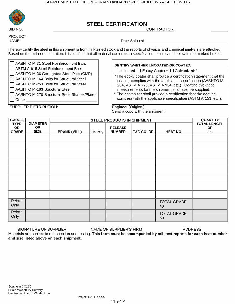
SUPPLEMENT TO THE UNIFORM STANDARD SPECIFICATIONS – SECTION 115
Southern CC215 Bruce Woodbury Beltway Las Vegas Blvd to Windmill Ln Project No. L-XXXX
STEEL CERTIFICATION BID NO. CONTRACTOR:
PROJECT NAME: Date Shipped
I hereby certify the steel in this shipment is from mill-tested stock and the reports of physical and chemical analysis are attached. Based on the mill documentation, it is certified that all material conforms to specification as indicated below in the marked boxes.
AASHTO M-31 Steel Reinforcement Bars ASTM A 615 Steel Reinforcement Bars
IDENTIFY WHETHER UNCOATED OR COATED:
AASHTO M-36 Corrugated Steel Pipe (CMP) AASHTO M-164 Bolts for Structural Steel AASHTO M-253 Bolts for Structural Steel AASHTO M-183 Structural Steel AASHTO M-270 Structural Steel Shapes/Plates Other _________________________________
Uncoated Epoxy Coated* Galvanized** *The epoxy coater shall provide a certification statement that the
coating complies with the applicable specification (AASHTO M 284, ASTM A 775, ASTM A 934, etc.). Coating thickness measurements for the shipment shall also be supplied.
**The galvanizer shall provide a certification that the coating complies with the applicable specification (ASTM A 153, etc.).
SUPPLIER DISTRIBUTION: Engineer (Original) Send a copy with the shipment
STEEL PRODUCTS IN SHIPMENT GAUGE, TYPE OR
GRADE
QUANTITY TOTAL LENGTH
OR (lb)
DIAMETER OR
SIZE RELEASE NUMBER BRAND (MILL) TAG COLOR HEAT NO. Country
Rebar TOTAL GRADE Only 40 Rebar TOTAL GRADE Only 60
SIGNATURE OF SUPPLIER NAME OF SUPPLIER'S FIRM ADDRESS
Materials are subject to reinspection and testing. This form must be accompanied by mill test reports for each heat number and size listed above on each shipment.
115-12

SUPPLEMENT TO THE UNIFORM STANDARD SPECIFICATIONS - SECTION 116
SECTION 116
CONTRACTOR QUALITY CONTROL TESTING REPORT SUMMARY FORMS
116.01 General
This section contains the document templates that shall be used by the contractor. If the Contractor would like to revise or use other documents in the quality control, they may be submitted to the Engineer for approval before use.
116.02 Section Content
The forms that are included are listed below: (a) Soils and Aggregate Test Result Summary (b) Hot-Mix Asphalt Summary (c) Soil and Aggregate Density Summary (d) Concrete Summary (e) Proctor Summary (f) Asphalt Density Summary
Southern CC215 Bruce Woodbury Beltway Las Vegas Blvd to Windmill Ln Project No. L-XXXX
116 - 1

SUPPLEMENT TO THE UNIFORM STANDARD SPECIFICATIONS - SECTION 116
Clark County Department of Public Works500 So. Grand Central Parkway
Las Vegas, NV 89155Phone (702) 455-4107
Fax (702) 455-6113
TEST
No.
DA
TE S
AM
PLED
MA
XIM
UM
DR
Y D
ENSI
TY (P
CF)
OPT
IMU
M
MO
ISTU
RE
(%)
MA
TER
IAL
TYPE
R-V
ALU
E
LIQ
UID
LIM
IT
PLA
STIC
LIM
IT
PLA
STIC
ITY
IND
EX
pH
RES
ITIV
ITY
(OH
M/C
M)
CH
EMIC
AL
SOLU
BLE
SU
LFA
TE (P
PM)
MO
ISTU
RE
CO
NTE
NT
(%)
6" 3" 2"
1-1/
2"
1" 3/4"
1/2"
3/8"
No.
4
No.
8
No.
10
No.
16
No.
30
No.
40
No.
50
No.
100
No.
200
PASS
/ FA
IL
LAB
OR
ATO
RY
No.
MODIFIED PROCTOR ATTERBERG LIMITS
Soils and Aggregate Test Result Summary
SIEVE ANALYSIS Percent Passing
Project Name:Bid Number:
Date:
Southern CC215 Bruce Woodbury Beltway Las Vegas Blvd to Windmill Ln Project No. L-XXXX
116 - 2
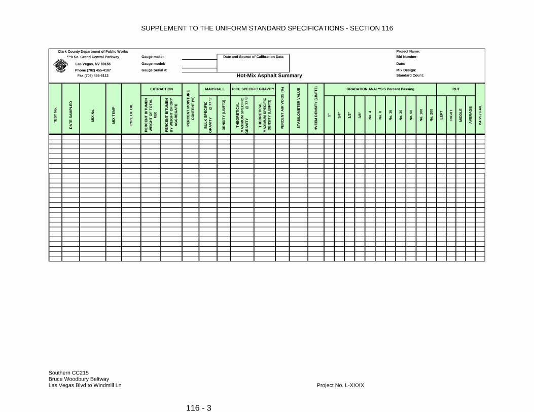
SUPPLEMENT TO THE UNIFORM STANDARD SPECIFICATIONS - SECTION 116
Clark County Department of Public Works500 So. Grand Central Parkway
Las Vegas, NV 89155
Phone (702) 455-4107Fax (702) 455-6113
TEST
No.
DA
TE S
AM
PLED
MIX
No.
MIX
TEM
P
TYPE
OF
OIL
PER
CEN
T B
ITU
MEN
W
EIG
HT
OF
TOTA
L M
IX
PER
CEN
T B
ITU
MEN
B
Y W
EIG
HT
OF
DR
Y A
GG
REG
ATE
BU
LK S
PEC
IFIC
G
RA
VITY
@ 7
7 °F
DEN
SITY
(LB
/FT3
)
THEO
RET
ICA
L M
AXI
MU
M S
PEC
IFIC
G
RA
VITY
@
77
°F
THEO
RET
ICA
L M
AXI
MU
M S
PEC
IFIC
D
ENSI
TY (L
B/F
T3)
1" 3/4"
1/2"
3/8"
No.
4
No.
8
No.
16
No.
30
No.
50
No.
100
No.
200
LEFT
RIG
HT
MID
DLE
AVE
RA
GE
PASS
/ FA
IL
STA
BIL
OM
ETER
VA
LUE
HVE
EM D
ENSI
TY (L
B/F
T3)
GRADATION ANALYSIS Percent Passing
Gauge make: Date and Source of Calibration Data
Gauge model:
Gauge Serial #:
RUT
PER
CEN
T A
IR V
OID
S (%
)
Hot-Mix Asphalt Summary Standard Count:
EXTRACTION
PER
CEN
T M
OIS
TUR
E C
ON
TEN
T (%
)
MARSHALL RICE SPECIFIC GRAVITY
Project Name:Bid Number:
Date:
Mix Design:
Southern CC215 Bruce Woodbury Beltway Las Vegas Blvd to Windmill Ln Project No. L-XXXX
116 - 3

SUPPLEMENT TO THE UNIFORM STANDARD SPECIFICATIONS - SECTION 116
Age (Days)
Test Result
Age (Days)
Test Result
Age (Days)
Test Result
Age (Days)
. Test Result
Age (Days)
Test Result
Age (Days)
Test Result
Age (Days)
Test Result
Age (Days)
Test Result
Age (Days)
Test Result
Age (Days)
Test Result
Age (Days)
Test Result
Age (Days)
Test Result
Age (Days)
Test Result
Age (Days)
Test Result
Age (Days)
Test Result
Age (Days)
Test Result
Material DescriptionTest No.
28 Days AverageDate CastUnit Wt.Slump
QUALITY CONTROL SUMMARY - Concrete
Highlighted items are current period entriesStrength Results are as reported by Converse Consultants
Mix No.Location/Source of
SampleBid Item No. Required (P)ass or (F)ail RemarksBreak Results
Southern CC215 Bruce Woodbury Beltway Las Vegas Blvd to Windmill Ln Project No. L-XXXX
116 - 4

SUPPLEMENT TO THE UNIFORM STANDARD SPECIFICATIONS - SECTION 116
TEST
No.
DA
TE
LOC
ATI
ON
OFF
SET
DEP
TH O
F TE
ST
ELEV
ATI
ON
R
EFER
ENC
E
FEET
BEL
OW
EL
EV. R
EF.
WET
DEN
SITY
C
OU
NT
WET
DEN
SITY
(P
CF)
MO
ISTU
RE
CO
UN
T
MO
ISTU
RE
(PC
F)
FIEL
D D
RY
DEN
SITY
(PC
F)
FIEL
D
MO
ISTU
RE
(%)
PRO
CTO
R
VALU
E
MA
XIM
UM
DR
Y D
ENSI
TY (P
CF)
OPT
IMU
M
MO
ISTU
RE
(%)
REL
ATI
VE
CO
MPA
CTI
ON
(%
)
PASS
/ FA
IL
Project Name:
Bid Number:
Soil and Aggregate Density Summary
Clark County Department of Public Works
500 So. Grand Central ParkwayLas Vegas, NV 89155Phone (702) 455-4107
Fax (702) 455-6113
Date:Gauge make:
Gauge Serial #:
Date and Source of Calibration Data
Standard Count:Mix Design:
Gauge model:
Southern CC215 Bruce Woodbury Beltway Las Vegas Blvd to Windmill Ln Project No. L-XXXX
116 - 5

SUPPLEMENT TO THE UNIFORM STANDARD SPECIFICATIONS - SECTION 116
Clark County Department of Public Works500 So. Grand Central Parkway Bid Number:Las Vegas, NV 89155Phone (702) 455-4107Fax (702) 455-6113
PRO
CTO
R
No.
SAM
PLE
LOC
ATI
ON
SOIL
TYP
E (C
LASS
)
SOIL DESCRIPTION
MIN
IMU
M
VALU
E
MA
XIM
UM
VA
LUE
OPT
IMU
M
VALU
E
Proctor Summuary
Project Name:
Date
Southern CC215 Bruce Woodbury Beltway Las Vegas Blvd to Windmill Ln Project No. L-XXXX
116 - 6

SUPPLEMENT TO THE UNIFORM STANDARD SPECIFICATIONS - SECTION 116
Southern CC215 Bruce Woodbury Beltway Las Vegas Blvd to Windmill Ln Project No. L-XXXX
116 - 7
Clark County Department of Public Works500 So. Grand Central Parkway
Las Vegas, NV 89155Phone (702) 455-4107
Fax (702) 455-6113
TEST
No.
Mix
Des
ign
(com
men
t #
belo
w)
DA
TE LOCATION OFFSET
Bac
ksca
tter
(BS)
Dire
ct
Tran
s (D
T)
LIFT
(1,2
,3)
DEP
TH O
F TE
ST
ELEV
ATI
ON
R
EFER
ENC
E
DEN
SITY
C
OU
NT
DEN
SITY
(PC
F)
DEN
SITY
C
OU
NT
DEN
SITY
(PC
F)
DEN
SITY
C
OU
NT
DEN
SITY
(PC
F)
DEN
SITY
C
OU
NT
DEN
SITY
(PC
F)
TEST
AVE
RA
GE
DEN
SITY
(PC
F)
CO
RR
ECTI
ON
FA
CTO
R
CO
RR
ECTE
D
DEN
SITY
(PC
F)
RICE
REL
ATI
VE
CO
MPA
CTI
ON
(%
)D
AIL
Y A
VER
AG
E R
ELA
TIVE
C
OM
PAC
TIO
N
(%)
Project Name:Bid Number:
Test 1 Test 2 Test 3 Test 4
Asphalt Density Summary
Gauge model:Gauge Serial #:
Gauge make: Date and Source of Calibration Data
Standard Count:
Date:

SUPPLEMENT TO THE UNIFORM STANDARD SPECIFICATIONS - SECTION 116
THIS PAGE INTENTIONALLY LEFT BLANK
Southern CC215 Bruce Woodbury Beltway Las Vegas Blvd to Windmill Ln Project No. L-XXXX
116 - 8

SUPPLEMENT TO THE NDOT STANDARD SPECIFICATIONS - SECTION 200
SECTION 200
ENGINEERING
DESCRIPTION 200.01.01 General Add the following to this Subsection: Section 105.08 of these special provisions lists construction stakes, lines and grades to be provided by the owner. Delete the third and fourth paragraphs of this Subsection. (Check with survey Division)
Southern CC215 Bruce Woodbury Beltway Las Vegas Blvd to Windmill Ln Project No. L-XXXX 200 - 1

SUPPLEMENT TO THE NDOT STANDARD SPECIFICATIONS - SECTION 201
SECTION 201
CLEARING AND GRUBBING
METHOD OF MEASUREMENT 201.04.01 Measurement Add the following to this Subsection: Cleaning and grubbing will not be measured for payment. Removal of existing ground cover and other deleterious material shall be included in the various items of work involved. The quantity of tree relocation and salvage measured for payment shall be the number of each complete and in place. The quantity of fine grading and soil preparation measured for payment shall be the number of square feet complete and in place.
BASIS OF PAYMENT
201.05.01 Payment Add the following to this Subsection: The accepted quantity of tree relocation and salvage will be paid for at the contract unit price bid per each, which shall be full compensation for all labor, materials, tools, equipment, excavation, storage and incidentals to complete the work as shown on the Drawings, as specified, and as directed by Engineer. The accepted quantity of fine grading and soil preparation will be paid for at the contract unit price bid per square foot, which shall be full compensation
Payment will be made under:
Pay Item Pay Unit Tree Removal................................................................................. Each Tree Relocation and Salvage ......................................................... Each Fine Grading and Soil Preparation ......................................Square Foot
Southern CC215 Bruce Woodbury Beltway Las Vegas Blvd to Windmill Ln Project No. L-XXXX 201 - 1
SUPPLEMENT TO THE NDOT STANDARD SPECIFICATIONS - SECTION 202
SECTION 202
REMOVAL OF STRUCTURES AND OBSTRUCTIONS
DESCRIPTION 202.01.01 General Add the following to this Subsection: This work also consists of removing a portion of bridge I-1973R, H-1971, H-2040, B-1970, I-1972, I-1972R, and I-1973. This work also consists of removal of MSE wall. This work also consists of removal of sound wall. This work also consists of removal of masonry wall. This work also consists of removal of pavement marking. This work also consists of removal and salvage of gravel mulch. This work also consists of removing headwall. This work also consists of removing concrete channel. This work also consists of removing East wall of concrete channel. This work also consists of removing slotted drain (length). This work also consists of removing storm drain pipe. 202.03.01 General Add the following to this Subsection: Make the necessary adjustments to the fire hydrant in accordance with the requirements of the City of Henderson Fire Department. The bituminous and concrete pavement material maybe incorporated into the embankment, if the material is pulverized so that the particles do not exceed eight inches (8”). Southern CC215 Bruce Woodbury Beltway Las Vegas Blvd to Windmill Ln Project No. L-XXXX 202 - 1

SUPPLEMENT TO THE NDOT STANDARD SPECIFICATIONS - SECTION 202
CONSTRUCTION
202.03.02 Removal Add the following to this Subsection: The work for removal of portion of bridge includes removing the existing concrete slope paving, concrete, and reinforcing on portions of the existing wing walls, bridge rails, approach slabs and sound walls on bridge railings and approach slabs as shown on the plans and as directed by the Engineer. The work for removal of embankment protector includes removing the slotted drain corrugated metal pipe, down drain corrugated metal pipe, drop inlet with grade and anchor assemblies. Remove pavement marking film – traffic lines by using equipment with a combination of chemical and high pressure water, or by other approved means. Completely remove tape in such a manner that no residue or any other trace of the tape may be misconstrued by a driver to be a traffic marking under any condition of daylight, darkness, wetness of the pavement. Exercise care to prevent damage to the pavement surface. Fill in the depression left from the removal of pavement markings with an approved material. The footings for existing sound walls shall be removed to a depth of not less than six inches below the proposed roadway structural section to be constructed. Existing pavement to remain in place shall be protected form damage. All incidental damage to pavements shall be repaired in a manner approved by the Engineer. Remove headwalls in such a manner as to prevent damage to existing culvert. Repair, replace or remove existing culvert as directed. 202.03.08 Salvage Add the following to this Subsection: Transport and stockpile the removed chain link fence at approved locations. Salvage light poles and deliver to the Clark County Operations Shop located at 4315 Stephanie Street, Las Vegas, Nevada. Transport and stockpile the removed gates at approved locations. Transport and stockpile the removed guardrail at approved locations. Southern CC215 Bruce Woodbury Beltway Las Vegas Blvd to Windmill Ln Project No. L-XXXX 202 - 2

SUPPLEMENT TO THE NDOT STANDARD SPECIFICATIONS - SECTION 202
Transport and stockpile the removed gravel mulch at approved locations.
METHOD OF MEASUREMENT
202.04.01 Measurement Add the following to this Subsection: The quantities of removal of bituminous pavement and removal of concrete pavement will not be measured for payment directly and will be included in the quantity of roadway excavation measured in Section 203. The quantity of removal of chain link fence measured for payment will be the number of linear feet removed. The quantity of removal of composite surface measured for payment will be the number of cubic yards removed. The quantity of removal of concrete barrier rail measured for payment will be the number of linear feet removed. The quantity of removal of curb and gutter measured for payment will be the number of linear feet removed. The quantity of remove drop inlet measured for payment will be the number of each removed. The quantity of removal of guardrail measured for payment will be the number of linear feet removed. The quantity for remove impact attenuator will be measured for payment by the each. The quantity of remove manhole measured for payment will be the number of each removed. The quantity of removal of masonry wall measured for payment will be the number of linear feet removed. The quantity of removal of median island measured for payment will be the number of square yards removed. The quantity of removal of sidewalk measured for payment will be the number of square yards removed. Southern CC215 Bruce Woodbury Beltway Las Vegas Blvd to Windmill Ln Project No. L-XXXX 202 - 3

SUPPLEMENT TO THE NDOT STANDARD SPECIFICATIONS - SECTION 202
The quantity of remove slotted drain (length) measured for payment will be the number of each removed. The quantity of removal of MSE wall measured for payment will be the number of square feet removed. The quantity of removal of sound wall measured for payment will be the number of linear feet removed. The quantity of remove storm drain pipe measured for payment will be the number of linear feet removed. The quantity of remove portion of bridge (number) will be measured for payment on a lump sum basis. The quantity of salvage gravel mulch shall be measured for payment on a lump sum basis. The quantity of removal of pavement marking measured for payment will be the number of square feet removed. The quantity of removal of raised pavement marking will not be measured for payment directly and will be considered incidental to the various other items of work. The quantity of remove headwall measured for payment will be the number of each removed. The quantity of remove concrete channel measured for payment will be the number of linear feet removed. The quantity of remove East wall of concrete channel will be the number of linear feet removed.
BASIS OF PAYMENT
202.05.01 Payment Add the following to this Subsection: The accepted quantity of the removal of chain link fence will be paid for at the Contract unit price bid per linear foot, which shall be full compensation for removal and salvage of existing fence. At Contractor’s option, salvaged chain link fence and hardware may be refurbished and reused on the project where new fencing is to be installed as specified in Section 616. Compensation for installing the refurbished chain link fence will be paid at the Contract unit price Southern CC215 Bruce Woodbury Beltway Las Vegas Blvd to Windmill Ln Project No. L-XXXX 202 - 4

SUPPLEMENT TO THE NDOT STANDARD SPECIFICATIONS - SECTION 202
bid for installation of chain link fence. Fence posts shall not be reused. The refurbished fencing and hardware shall be approved by Engineer, prior to installation. The accepted quantity of the removal of composite surface will be paid for at the Contract unit price bid per cubic yard, which shall be full compensation for removal and disposal in accordance with this section. There is no direct payment for saw cutting for the removal of composite surface. The accepted quantity of the removal of concrete barrier rail will be paid for at the Contract unit price bid per linear foot, which shall be full compensation for removal and disposal in accordance with this section. Payment for concrete barrier rail removal shall also include saw cutting. There is no direct payment for saw cutting for the removal of concrete barrier rail. The accepted quantity of the removal of curb and gutter will be paid for at the Contract unit price bid per linear foot, which shall be full compensation for removal and disposal in accordance with this section. Payment for Curb and Gutter removal shall also include saw cutting. There is no direct payment for saw cutting for the removal of curb and gutter. The accepted quantity of the remove drop inlet will be paid for at the Contract unit price bid per each, which shall be full compensation for removal and disposal in accordance with this section. The accepted quantity of the removal of guardrail will be paid for at the Contract unit price bid per linear foot, which shall be full compensation for removal of existing guardrail and salvage of guard rail panels in accordance with this section. At Contractor’s option, salvaged guardrail and hardware may be refurbished and reused on the project where new guardrail is to be installed as specified in Section 618. Compensation for install the refurbished guardrail will be paid at the Contract unit price bid for installation of guardrail. Guardrail posts shall not be reused. The refurbished guardrail and hardware shall meet current safety standards and be approved by Engineer, prior to installation. The accepted quantity of the removal of impact attenuator will be paid for at the Contract unit price bid per each, which shall be full compensation for removal and disposal in accordance with this section. The accepted quantity of the remove manhole will be paid for at the Contract unit price bid per each, which shall be full compensation for removal and disposal in accordance with this section. The accepted quantity of the removal of masonry wall will be paid for at the Contract unit price bid per linear foot, which shall be full compensation for removal and disposal in accordance with this section. Southern CC215 Bruce Woodbury Beltway Las Vegas Blvd to Windmill Ln Project No. L-XXXX 202 - 5

SUPPLEMENT TO THE NDOT STANDARD SPECIFICATIONS - SECTION 202
The accepted quantity of the removal of median island will be paid for at the Contract unit price bid per square yard, which shall be full compensation for removal and disposal in accordance with this section. The accepted quantity of the removal of sidewalk will be paid for at the Contract unit price bid per square yard, which shall be full compensation for removal, disposal, and incidentals necessary to complete the sidewalk removal in accordance with this section. Payment for removal of concrete items shall include, in addition to other work specified, sawcutting where required. The accepted quantity of the remove slotted drain (length) will be paid for at the Contract unit price bid per each, which shall be full compensation for removal and disposal in accordance with this section. Existing sections of slotted drain to remain in place and adjacent pavement damaged or removed incidental to this bid item shall be replaced to original line and grade and will not be measured of paid for separately but will be considered as subsidiary to this item. The accepted quantity of the removal of MSE wall will be paid for at the Contract unit price bid per square foot, which shall be full compensation for removal and disposal in accordance with this section. The accepted quantity of the removal of sound wall will be paid for at the Contract unit price bid per linear foot, which shall be full compensation for removal and disposal in accordance with this section. The accepted quantity of the remove storm drain pipe will be paid for at the Contract unit price bid per linear foot, which shall be full compensation for the removal and disposal in accordance with this section. The accepted quantity of the removal of portion of bridge (number) will be paid for at the Contract unit price bid for the lump sum. Removal of portion of bridge (number) shall be full compensation for all incidental excavation and backfill; removal, salvage, haul, storage, and disposal of materials including the bridge rails, approach slabs, wingwalls, and appearances as shown on the plans and in accordance with this section. Payment for removal of portion of bridge shall include sawcutting and repair of damage to the existing bridge occurring as a result of removal operations and will not be measured of paid for separately but will be considered as subsidiary to these items. The accepted quantity of salvage gravel mulch will be paid for on a lump sum basis, which shall be full compensation for removal, stockpiling, and reuse in accordance with this section. Payment for salvage gravel mulch shall include, in addition to other work specified, reuse where required on the plans according to Section 202.03.08 of the Standard Specifications. Southern CC215 Bruce Woodbury Beltway Las Vegas Blvd to Windmill Ln Project No. L-XXXX 202 - 6

SUPPLEMENT TO THE NDOT STANDARD SPECIFICATIONS - SECTION 202
The accepted quantity of the removal of pavement marking will be paid for at the Contract unit price bid for each. The accepted quantity of the remove headwall will be paid for at the Contract unit price bid per each, which shall be full compensation for removal and disposal in accordance with this section. The accepted quantity of the removal of concrete channel will be paid for at the Contract unit price bid per linear foot, which shall be full compensation for removal and disposal of concrete channel in accordance to this section. The accepted quantity of the remove of East wall of concrete channel will be paid for at the Contract unit price bid per linear foot, which shall be full compensation for removal and disposal of East wall of concrete channel in accordance to this section. Payment will be made under:
Pay Item Pay Unit Removal of Chain Link Fence .............................................. Linear Foot Removal of Composite Surface.............................................Cubic Yard Removal of Concrete Barrier Rail ........................................ Linear Foot Removal of Curb and Gutter ................................................ Linear Foot Remove Drop Inlet ......................................................................... Each Removal of Guard Rail ......................................................... Linear Foot Removal of Impact Attenuator ...................................................... Each Remove Manhole .......................................................................... Each Removal of Masonry Wall .................................................... Linear Foot Removal of Median Island.................................................. Square Yard Removal of Sidewalk ......................................................... Square Yard Remove Slotted Drain (10 ft).......................................................... Each Remove Slotted Drain (20 ft).......................................................... Each Remove Slotted Drain (30 ft).......................................................... Each Removal of MSE Wall .........................................................Square Foot Removal of Sound Wall....................................................... Linear Foot Remove Storm Drain Pipe.................................................... Linear Foot Removal of Portion of Bridge I-1973R................................... Lump Sum Removal of Portion of Bridge H-1971.................................... Lump Sum Removal of Portion of Bridge H-2040.................................... Lump Sum Removal of Portion of Bridge B-1970.................................... Lump Sum Removal of Portion of Bridge I-1972 .....................................Lump sum Removal of Portion of Bridge I-1972R................................... Lump Sum Removal of Portion of Bridge I-1973 ..................................... Lump Sum
Southern CC215 Bruce Woodbury Beltway Las Vegas Blvd to Windmill Ln Project No. L-XXXX 202 - 7

SUPPLEMENT TO THE NDOT STANDARD SPECIFICATIONS - SECTION 202
Salvage Gravel Mulch ........................................................... Lump Sum Removal of Pavement Marking ...................................................... Each Remove Headwall .......................................................................... Each Remove Concrete Channel .................................................. Linear Foot Remove East wall of Concrete Channel............................... Linear Foot
Southern CC215 Bruce Woodbury Beltway Las Vegas Blvd to Windmill Ln Project No. L-XXXX 202 - 8
SUPPLEMENT TO THE NDOT STANDARD SPECIFICATIONS - SECTION 203
SECTION 203
EXCAVATION AND EMBANKMENT
DESCRIPTION
Add the following Subsections to this Section: 203.01.02 General This work also consists of obtaining the required bearing capacity at: Bridge No. I-2884R, EB I-215 to Sunset, Abutment 2. Bridge No. I-2886R, Ramp “WS-5” over Warm Springs, Abutment 1 and 2.
Bridge No. I-1973R, WB I-215 to Airport Connector, Abutment 1, Pier 1, 2, 3, and Abutment 2.
Bridge No. I-1972, I-215 over Warm Springs, Abutment 2.
MATERIALS 203.02.01 Roadway Excavation Add the following to this Subsection: The bituminous and concrete pavement material may be incorporated into the embankment if the material is pulverized so that the particles do not exceed 8 inches in size. The pulverized bituminous and concrete pavement shall not be placed within the top three (3) feet below the subgrade and shall not be placed within the alignment of underground facility trenches. 203.02.03 Channel Excavation Add the following of this Subsection: The bituminous and concrete pavement material may be incorporated into the embankment if the material is pulverized so that the particles do not exceed 8 inches in size. The pulverized bituminous and concrete pavement shall not be placed within the top three (3) feet below the subgrade and shall not be placed within the alignment of underground facility trenches. 203.02.05 Selected Borrow Add the following of this Subsection: The existing subgrade material below existing footing widenings should be overexcavated below the bottom of the depth specified. The overexcavation Southern CC215 Bruce Woodbury Beltway Las Vegas Blvd to Windmill Ln Project No. L-XXXX 203 - 1

SUPPLEMENT TO THE NDOT STANDARD SPECIFICATIONS - SECTION 203
should extend laterally from the edge of the foundation a distance equal to the specified overexcavation depth; however, it should not extend beyond a 1:1 (horizontal to vertical) influence zone line drawn from the edge of the existing footings. Overexcavation can be terminated at shallower than recommended depths if partially or fully cemented soils are encountered upon approval of the Engineer. The bottom of the overexcavated area should be scarified to a depth of 6 inches, moisture conditioned, and compacted to 95 percent maximum dry density per NDOT Test Method T101. The scarification recommendation can be waived by the geotechnical engineer if, upon inspection, partially or fully cemented soils are encountered The overexcavated soils should be replaced with import structural fill material meeting Selected Borrow requirements. Placement and compaction of the Selected Borrow should be performed in accordance with requirements of Section 203 of NDOT Standard Specifications, including keying into existing slopes, maximum lift thickness, minimum after completion density of 95 percent maximum dry density per NDOT Test Method T101, and other applicable requirements. If the existing native or fill material satisfies Selected Borrow material specifications, such material may be used as backfill in the overexcavation in accordance with the placement and compaction criteria specified above. The required depth of excavation shall be as follows. Bridge No. I-2884R, Abutment 2 = 3.0’ Bridge No. I-2886R, Abutment 1 = 3.0’ Bridge No. I-1973R, Abutment 1 = 3.0’ Bridge No. I-1973R, Pier 1 = 4.0’ Bridge No. I-1973R, Pier 2 = 4.5’ Bridge No. I-1973R, Pier 3 = 5.0’ Bridge No. I-1973R, Abutment 2 = 3.5’ Bridge No. I-1972, Abutment 2 = 4.0’ Bridge No. I-1973, Abutment 1 = 3.0’ Bridge No. I-1973, Abutment 2 = 3.0’ Prior to placement, a minimum of 2-inch direct shear test should be performed on approved Selected Borrow fill material from each source (import or on-site) to verify that the minimum friction angle of 36 degrees is achieved at the specified level of compaction. At the request of the Engineer, additional 2-inch direct shear tests shall be performed. Following placement and compaction of the foundation subgrade material, plate load test should be performed in accordance with ASTM test method D1196 under the supervision of the geotechnical engineer to verify the bearing capacity Southern CC215 Bruce Woodbury Beltway Las Vegas Blvd to Windmill Ln Project No. L-XXXX 203 - 2

SUPPLEMENT TO THE NDOT STANDARD SPECIFICATIONS - SECTION 203
of the prepared foundation subgrade. The number of load tests can be limited to 1 at each footing location, provided that the geotechnical engineer selects the most critical location within the foundation footprint, and both quality control and assurance indicated that the subgrade under all foundations was prepared in accordance with the contract specifications.
METHOD OF MEASUREMENT
203.04.01 Measurement Add the following to this Subsection: The quantity of roadway excavation measured for payment shall include removal of bituminous and concrete pavement as specified in Section 202. Measurement for payment for select borrow embankment will not be made and shall be included in the price bid for construct bridge as specified in Section 502. Measurements for payment for the direct shear tests and the plate load tests required by this section will not be made and shall be considered as incidental to the bid item for Quality Control. Subparagraph (e) on the top of Page 94 of the Standard Specifications is hereby deleted and the following substituted therefore: (e) Surplus Material. Surplus excavated material will be measured for
payment as roadway excavation and no further compensation will be allowed by virtue of the method of disposing, placing, or widening embankments caused from such surplus material.
BASIS OF PAYMENT
203.05.01 Payment Add the following to this Subsection: Between the date the project is advertised and bid opening date, it shall be the Contractors responsibility to independently verify the quantities of Roadway Excavation and Selected Borrow and the Contractor shall include in his bid price any perceived differences with those quantities as shown in the Bid Form. No additional payment will be allowed based on any changes to these quantities after bids are opened except where there is an additional scope of work change ordered by the Engineer.
Southern CC215 Bruce Woodbury Beltway Las Vegas Blvd to Windmill Ln Project No. L-XXXX 203 - 3

SUPPLEMENT TO THE NDOT STANDARD SPECIFICATIONS - SECTION 203
Applications of pre-emergent herbicide and dust palliative will be paid for as specified in Sections 212 and 637. Payment will be made under:
Pay Item Pay Unit Borrow Embankment.............................................................Cubic Yard Drainage Excavation .............................................................Cubic Yard Roadway Excavation.............................................................Cubic Yard
Southern CC215 Bruce Woodbury Beltway Las Vegas Blvd to Windmill Ln Project No. L-XXXX 203 - 4
SUPPLEMENT TO THE NDOT STANDARD SPECIFICATIONS - SECTION 210
SECTION 210
WATERING
CONSTRUCTION
This Subsection of the Standard Specifications is hereby deleted and the following substituted therefore: 210.03.03 Water Supply (a) General. Provide an adequate water supply. Negotiate with water owner(s) of supply and sign an agreement with each owner before removing the water. Furnish a copy of said agreement. Pay all royalties occurring under such agreements and also obtain any necessary right of way. (b) Water Wells and Well Points for Dewatering. Be aware that water usage may be limited in the project area. Monitoring the usage and effects on adjacent wells may also be required by the Department of Conservation and Natural Resources, Division of Water Resources. Contact the Office of the State Engineer for possible restrictions at (702) 486-2770 in Southern Nevada and (775) 684-2800 in Northern Nevada. If electing to obtain water from an existing well or to drill a well for highway construction purposes, request a waiver be issued in accordance with Nevada Revised Statutes and the Nevada Administrative code. File all requests for waiver to the Engineer on the form from the Division of Water Resources website (http://water.nv.gov/). Ensure the request package includes the following information:
1. The location of the proposed water well by public survey, county assessor’s parcel number and plot map.
2. The project and contract number. 3. The total amount of water that will be consumed each day. 4. The name, address, and telephone number of the person responsible for
plugging the well. Also include the name, address, and telephone number of the owner of the land where the well is located if not the same as the person responsible for plugging the well.
5. A notarized affidavit signed by the person responsible for plugging the well which states that they will be responsible for plugging the well if it is abandoned.
6. The name, address, and telephone number of a person who will be available to answer questions concerning the contract.
7. The date the contract is scheduled to be completed. Southern CC215 Bruce Woodbury Beltway Las Vegas Blvd to Windmill Ln Project No. L-XXXX 210 - 1

SUPPLEMENT TO THE NDOT STANDARD SPECIFICATIONS - SECTION 210
Maintain a copy of the approved waiver onsite at all times during drilling operations. Should circumstances dictate that the well location be moved outside of the 40 (forty) acre subdivision described on the approved waiver, request an amendment using the correct Division of Water Resources form. By signing and submitting a request for a waiver, agree to the following:
1. Comply with the requirements of the waiver. 2. Use a water driller licensed in Nevada to perform all drilling and plugging.
All drilling and plugging shall be in accordance with the “Regulations For Drilling Water Wells”, current edition, which may be obtained from the Office of the State Engineer, Division of Water Resources, 901 S. Stewart Street, Suite 2002, Carson City, Nevada 89701-5250, phone (775) 684-2800.
3. Use the new well for highway construction purposes only, no other use will be considered or allowed.
4. Within 3 days of completion of the contract, defined as District acceptance, plug the well in accordance with the requirements of the Office of the State Engineer.
5. Notify the Office of the State Engineer of plugging within 30 days of contract completion. Provide a copy of said notification.
(c) Changes in the Diversion or Use of Surface Water. If electing to obtain water by a change in the place of diversion, manner of use or place of use of water already appropriated, apply for a permit in accordance with NRS 533.345. The application for the permit to change the place of diversion, manner of use or place of use of water, already appropriated, may be obtained from and shall be filed with the Department of Conservation and Natural Resources, Office of the State Engineer, Division of Water Resources, 901 S. Stewart Street, Suite 2002, Carson City, Nevada 89701-5250, phone (775) 684-2800.
BASIS OF PAYMENT
This Subsection of the Standard Specifications is hereby deleted and the following substituted therefore: 210.05.01 Payment Full compensation for developing an adequate water supply, for furnishing all necessary equipment, for obtaining water from the source or sources, for water, for furnishing of equipment necessary to apply the water, and for monitoring shall be considered as included in the contract unit price paid for other appropriate items and no separate payment will be made therefore.
Southern CC215 Bruce Woodbury Beltway Las Vegas Blvd to Windmill Ln Project No. L-XXXX 210 - 2
SUPPLEMENT TO THE NDOT STANDARD SPECIFICATIONS - SECTION 211
SECTION 211
EROSION CONTROL
METHOD OF MEASUREMENT
This Subsection of the Standard Specification is hereby deleted and the following substituted therefore:
211.04.01 Measurement The quantities of all erosion control devices, including topsoil, seeding, hydro-seeding, fertilizing, mulching, erosion control fabric, and soil stabilizer will be measured for payment on a lump sum basis.
BASIS OF PAYMENT
This Subsection of the Standard Specifications is hereby deleted and the following substituted therefore: 211.05.01 Payment The accepted quantity of erosion control will be paid for at the Contract lump sum bid price, which shall be full compensation for providing all labor, equipment, materials, topsoil, seeding, hydro-seeding, fertilizing, mulching, erosion control fabric, and soil stabilizer and incidentals necessary to complete the erosion control in accordance with all applicable provisions of Section 211 of the Standard Specifications, as specified, as shown on the Drawings, and as required by Engineer. Payment will be made under:
Pay Item Pay Unit Erosion Control ..................................................................... Lump Sum
Southern CC215 Bruce Woodbury Beltway Las Vegas Blvd to Windmill Ln Project No. L-XXXX 211 - 1
SUPPLEMENT TO THE NDOT STANDARD SPECIFICATIONS - SECTION 212
SECTION 212
LANDSCAPING
CONSTRUCTION 212.01.01 General This section is changed to read as follows: This work shall consist of removing, replacing and transplanting trees, bushes, ground cover and grasses in on-site areas wherein the work is necessary to match proposed off-site improvements. All work shall be performed in a manner such that the Landscaping is returned to original or better condition. The Contractor shall coordinate the landscaping work with the property owner. The Contractor shall tour the site, assess the landscape restoration area, become familiar with the extent of removal, replacement and repair and bid that amount which will cover all costs. 212.03.10 Protection of Existing Facilities The following is added to this Section: This work shall consist of the preservation of existing trees and landscape adjacent to new construction. A. Trees are to be protected with barriers that extend beyond the drip lines of
trees. Protection for these trees must be applied in one of the following ways:
1. Chain-Link Protection-Zone Fencing: Galvanized-steel fencing fabricated from minimum 2-inch (50-mm) opening, 0.148-inch- (3.76-mm-) diameter wire chain-link fabric; with pipe posts, minimum 2-3/8-inch- (60-mm-) OD line posts, and 2-7/8-inch- (73-mm-) OD corner and pull posts; with 1-5/8-inch- (42-mm-) OD top rails and 0.177-inch- (4.5-mm-) diameter bottom tension wire; with tie wires, hog ring ties, and other accessories for a complete fence system.
2. Plywood Protection-Zone Fencing: Plywood framed with four 2-by-4-inch (50-by-100-mm) rails, with 4-by-4-inch (100-by-100-mm) preservative-treated wood posts spaced not more than 8 feet (2.4 m) apart.
3. Wood Protection-Zone Fencing: Constructed of two 2-by-4-inch (50-by-100-mm) horizontal rails, with 4-by-4-inch (100-by-100-mm) preservative-treated wood posts spaced not more than 8 feet
Southern CC215 Bruce Woodbury Beltway Las Vegas Blvd to Windmill Ln Project No. L-XXXX 212 - 1

SUPPLEMENT TO THE NDOT STANDARD SPECIFICATIONS - SECTION 212
(2.4 m) apart, and lower rail set halfway between top rail and ground.
4. Plastic Protection-Zone Fencing: Plastic construction fencing constructed of high-density extruded and stretched polyethylene fabric with 2-inch (50-mm) maximum opening in pattern and supported by tubular or T-shape galvanized-steel posts spaced not more than 8 feet (2.4 m) apart. High-visibility orange color, nonfading.
5. Height of Fencing: [4 feet (1.2 m)] [6 feet (1.8 m)] [8 feet (2.4 m)] <Insert dimension>.
6. Gates: Swing access gates matching material and appearance of fencing, to allow for maintenance activities within protection zones.
B. Protection-Zone Signage: Shop-fabricated, rigid plastic or metal sheet with attachment holes prepunched and reinforced; legibly printed with nonfading lettering.
C. In cases where the trees to be saved cannot be fully protected to the required extent, the encroachment into the protected area must be indicated on the site plan and effort must be made to do as little damage to the tree as is possible. Within the protective fencing the area should be augmented with 3 inches of organic mulch prior to the beginning of work. The key to tree survival is the protection of the roots during and after construction including preventing soil compaction and severed roots. This may require: 1. Additional fertilization 2. Above-grade curbing 3. The elimination of curbing 4. Root bridging 5. Tunneling under roots 6. Retaining walls 7. Rerouting utility lines
D. Any breaks or scrapes should be repaired immediately.
E. To prevent adverse effects of changes to the soil chemistry 1. Spread heavy plastic to protect the ground where concrete is mixed
or where sheetrock will be cut. The alkalinity can change the soil pH.
2. Do not use wood products containing pentachlorophenol which is deadly to roots. CCA-treated timber (greenish colored) is a safer alternative.
3. Paint brushes and tools should not be cleaned under trees. 4. Dispose of chemical waste (paint thinner, engine oil, etc.) properly
Southern CC215 Bruce Woodbury Beltway Las Vegas Blvd to Windmill Ln Project No. L-XXXX 212 - 2

SUPPLEMENT TO THE NDOT STANDARD SPECIFICATIONS - SECTION 212
F. Nothing should be attached to trees with staples, nails, screws, or other fastening devises. Use posts for signs, electrical wires, pulleys, etc.
G. Tree planting and maintenance, including pruning, must comply with the standards of the International Society of Arboriculture published in the American National Standards for Tree Care Operation published by the American National Standard Institute, Inc. (ANSI) 1995 edition.
H. Contractor shall be liable for replacement of any tree damaged during the course of construction. Determination shall be by Landscape Architect and Owner’s representative.
212.03.11 Plant Establishment Work The first sentence of the seventh paragraph of this Subsection of the Standard Specifications is hereby deleted. 212.03.12 Gravel Mulch The following is added to this Section: Prior to placement of gravel mulch, ensure that final grades are correct and all grading is complete. Apply first application of selective pre-emergent herbicide on the final grade. Water with light application of misting. Apply 2 inch minimum compacted thickness of crushed gravel mulch. Lightly water smoothed mulch layer to settle fines. Apply a second application of selective pre-emergent herbicide. 212.03.13 Pre-emergent Herbicide Apply pre-emergent herbicide at manufacturer’s recommended rate. Use pre-emergent herbicide products listed in Section 401 of the QPL.
METHOD OF MEASUREMENT 212.04.01 Measurement This Subsection of the Standard Specification is hereby deleted and the following substituted therefore: Measurement for landscaping shall be per lump sum. Pre-emergent herbicide shall not be measured for payment directly, and will be included in the price bid for the various items of work.
Southern CC215 Bruce Woodbury Beltway Las Vegas Blvd to Windmill Ln Project No. L-XXXX 212 - 3
SUPPLEMENT TO THE NDOT STANDARD SPECIFICATIONS - SECTION 212
BASIS OF PAYMENT 212.05.01 Payment This Section is changed to read as follows: The lump sum amount shall be full compensation for all work and material necessary to complete landscaping as specified herein, as shown on the project plans, and as directed by the Engineer. Payment shall include compensation for applying pre-emergent herbicide for landscaping, removing, replacing and/or relocating trees, plants, ground cover, re-sodding, planters and other landscape features and providing cut and fill grading to completely restore landscaping to an equal or better condition than the original. No additional payments will be made for any work associated with landscaping which is not specifically indicated herein. Payment will be made under: Pay Item Pay Unit
Landscaping.....................................................................Lump Sum
Southern CC215 Bruce Woodbury Beltway Las Vegas Blvd to Windmill Ln Project No. L-XXXX 212 - 4

SUPPLEMENT TO THE NDOT STANDARD SPECIFICATIONS - SECTION 213
SECTION 213
IRRIGATION SYSTEMS
213.01.01 General The following is added to this Subsection: This work shall also consist of removal and replacement of existing landscape irrigation system where it is necessary to modify such system to accommodate new improvements.
213.03.01 Construction The following is added to this Subsection: The specific irrigation facilities to be removed, modified, or replaced shall be determined in the field in consultation with the Engineer and the property owner. Where removal of irrigation system disrupts service to other landscaping outside the construction limits, the Contractor shall provide temporary connections until such time as permanent systems are functional. After completion of new improvements and site preparation, the Contractor shall construct and connect all irrigation facilities as nearly feasible to the original.
METHOD OF MEASUREMENT
This Subsection of the Standard Specification is hereby deleted and the following substituted therefore:
213.04.01 Measurement Remove and replace irrigation system shall be measured for payment on a lump sum basis.
BASIS OF PAYMENT
213.05.01 Payment The following is added to this subsection: The contract lump sum amount paid for remove and replace irrigation system shall be full compensation for removing existing systems, providing temporary connections, vertical and/or horizontal adjustments and for furnishing all in-kind replacement irrigation systems (i.e., sprinkler heads, ties, connectors, risers, etc.) Southern CC215 Bruce Woodbury Beltway Las Vegas Blvd to Windmill Ln Project No. L-XXXX 213 - 1

SUPPLEMENT TO THE NDOT STANDARD SPECIFICATIONS - SECTION 213
and providing all labor, materials, equipment and incidentals necessary to install and/or modify the existing irrigation systems as necessary to be functional with other existing facilities. Payment shall be made under: Pay Item Pay Unit
Remove and Replace Irrigation System......................Lump Sum
Southern CC215 Bruce Woodbury Beltway Las Vegas Blvd to Windmill Ln Project No. L-XXXX 213 - 2

SUPPLEMENT TO THE NDOT STANDARD SPECIFICATIONS - SECTION 302
SECTION 302
AGGREGATE BASE COURSES
CONSTRUCTION 302.03.01 Subgrade Preparation Add the following to this Subsection: The top six (6) inches of subgrade shall be scarified and compacted to not less than 90 percent relative compaction and the moisture content shall be within the ranges specified in Subsection 203.03.15.
METHOD OF MEASUREMENT
This Subsection of the Standard Specification is hereby deleted and the following substituted therefore: 302.04.01 Measurement Aggregate base (type) (class) will be measured by the cubic yard. The estimated quantities shown on the plans, plus or minus authorized quantity changes, will be the quantity used for payment. The Engineer or the Contractor may, however, request a final measurement, in which case final cross sections will be taken. Submit request for final measurement in writing. When final cross sections are taken the determination of quantities derived there from will be the quantities used for payment. If the Contractor requests final measurement and the quantities thus determined are equal to or less than the planned quantities plus authorized changes, the Contractor shall reimburse the Department for the Department’s expenses incurred by such final measurement.
BASIS OF PAYMENT
This Subsection of the Standard Specification is hereby deleted and the following substituted therefore:
302.05.01 Payment The accepted quantities of aggregate base (Type I) (Class B) material will be paid for at the Contract unit price bid per cubic yard and shall be full compensation for providing all labor, equipment, and incidentals for subgrade preparation, crushing, screening, mixing, hauling, placing, watering, compacting, and maintaining the base course as shown on the Drawings and as directed by the Engineer. Southern CC215 Bruce Woodbury Beltway Las Vegas Blvd to Windmill Ln Project No. L-XXXX 302 - 1

SUPPLEMENT TO THE NDOT STANDARD SPECIFICATIONS - SECTION 302
Payment will be made under:
Pay Item Pay Unit Aggregate Base (Type I) (Class B) .......................................Cubic Yard
Southern CC215 Bruce Woodbury Beltway Las Vegas Blvd to Windmill Ln Project No. L-XXXX 302 - 2

SUPPLEMENT TO THE NDOT STANDARD SPECIFICATIONS - SECTION 401
SECTION 401
PLANTMIX BITUMINOUS PAVEMENTS - GENERAL
MATERIALS 401.02.02 Composition of Mixtures The first three rows of the Mix Design Requirements Table on the bottom of page 147 of the Standard Specifications are hereby deleted and the following substituted therefore: Percent Air Voids of Compacted Bituminous Mixture (Types 2 and 3) AASHTO T269 * 4%
Percent Air Voids of Compacted Bituminous Mixture (Types 2C) AASHTO T269 * 5%
Percent Air Voids of Compacted Bituminous Mixture (Types 2 and 3) (Premixed) AASHTO T269 3 to 9%
* The mix design percent air void requirement may be adjusted to obtain passing values for other mix design requirements. The last paragraph on page 148 and the first five full paragraphs on page 149 of the Standard Specifications are hereby deleted and the following substituted therefore: On the first day of bituminous mix production, produce a trial mixture conforming to job-mix formula (1) during a maximum of 4 hours of operation, and no later than 1:00 p.m., to allow the Department sufficient time to evaluate the mixture. Produce the trial mixture at the medium speed used during the plant calibration. Place the trial mixture at an approved location. Suspend production of the bituminous mix for a maximum of 3 working days or until all test results, except for Indirect Tensile Strength (Unconditioned) or Indirect Tensile Strength (Retained Strength), are available. Working days will not be charged during the 3 working day suspension. Production may commence without the results of the Indirect Tensile Strength (Unconditioned) or Indirect Tensile Strength (Retained Strength) tests. Acceptance of the plant produced trial mixture will be based on tests results meeting the requirements of this Subsection with the aggregate gradation within the job mix ranges given and the in-place densities meeting the requirements of Subsection 402.03.06. When test results of the trial mixtures do not meet the requirements, additional plant trial mixtures may be required and the required tests performed during one
Southern CC215 Bruce Woodbury Beltway Las Vegas Blvd to Windmill Ln Project No. L-XXXX 401 - 1

SUPPLEMENT TO THE NDOT STANDARD SPECIFICATIONS - SECTION 401
additional maximum 3 working day suspension or a new mix design may be required. Remove field trial mixtures not meeting all the requirements of the specifications from the roadway. One half the quantity of rejected trial mixtures will be paid for at the applicable unit bid prices. Also one half of the removal quantity of rejected trial mixtures will be paid for at the applicable unit bid price. The other one half of the above quantities will not be paid for. A revised job-mix formula (if applicable) will be provided based on the results of the tests performed on the field trial plant produced mixture. The asphalt content will be selected, based on meeting the specifications for Hveem stability and percent air voids. Asphalt cement, PG 76-22NV shall be the only grade permitted for use in plantmix bituminous dense-graded and open-graded aggregate mixtures. The Department reserves the right to change the grade of the asphalt by one grade at no additional cost to the contract. The grade of asphalt to be used in the dense-graded bituminous mixtures will be determined by the Department based on a mix design using aggregates produced for the project. Once the determination of the grade and source of asphalt has been made, do not make changes unless new samples are submitted and a new design mix is approved. In the third row of the table on the bottom of page 149 of the Standard Specifications, the percent air void requirement for premixed Type 2 and 3 plantmix of "6 to 9%" is hereby deleted and "3 to 9%" substituted therefore. Final plantmix product placed on the roadway not conforming to the requirements specified herein will be assessed demerits according to the following schedule. See Subsection 109.02, where demerits will be evaluated for damages sustained by reason of any noncompliance.
Southern CC215 Bruce Woodbury Beltway Las Vegas Blvd to Windmill Ln Project No. L-XXXX 401 - 2

SUPPLEMENT TO THE NDOT STANDARD SPECIFICATIONS - SECTION 401
TEST
REQUIREMENT REJECTION LIMIT
DEMERITS
(a) Indirect Tensile Strength (Unconditioned) (Types 2 and 2C except with AC-10 Asphalt)
65 psi Min.
50 psi Min.
(b)
Indirect Tensile Strength (Unconditioned) (Type 3 except with AC-10 Asphalt)
58 psi Min.
43 psi Min.
(b)
Indirect Tensile Strength (Unconditioned) (With AC-10 Asphalt)
50 psi Min.
35 psi Min.
(b)
Indirect Tensile Strength, Retained Strength
70% Min.
55% Min.
(b)
(a) Demerits may be reduced or waived if bituminous material does not conform to Section 703. Demerits
apply only to the material produced on the shift the material was sampled. (b) Demerits will be assessed on a prorated basis by dividing the difference between the REQUIREMENT
and the TEST RESULT by the difference between the REQUIREMENT and the REJECTION LIMIT and multiplying by 21. The demerit value will be rounded down to the nearest whole demerit.
The temperature of the bituminous material just before mixing, and completed mixture in the hauling vehicle just before leaving the plant shall conform to the following:
BITUMINOUS MATERIAL
PLANTMIX SURFACE MIXTURE
PLANTMIX OPEN-GRADED MIXTURE GRADE OF
ASPHALT CEMENT MINIMUM
°F MAXIMUM
°F MINIMUM
°F MAXIMUM
°F MINIMUM
°F MAXIMUM
°F PG 76-22NV 300 350 290 350 290 325
The minimum temperature of the completed mixture at the hopper of the paver will be a single value determined by the Engineer, which shall conform to the following table, but shall not be more than 20°F lower than the temperature of the completed mixture leaving the plant, except for open-graded mixtures which shall not be more than 15°F lower than the temperature of the completed mixture leaving the plant.
PLANTMIX BITUMINOUS SURFACE MIXTURE
PLANTMIX BITUMINOUS OPEN-GRADED MIXTURE GRADE OF
ASPHALT CEMENT MINIMUM
°F MAXIMUM
°F MINIMUM
°F MAXIMUM
°F PG 76-22NV 285 350 285 325
Southern CC215 Bruce Woodbury Beltway Las Vegas Blvd to Windmill Ln Project No. L-XXXX 401 - 3
SUPPLEMENT TO THE NDOT STANDARD SPECIFICATIONS - SECTION 401
The third sentence of the second paragraph on page 151 of the Standard Specifications is hereby deleted and the following substituted therefore: Obtain samples from the produced stockpiles. If, at anytime during production, the bituminous mixture does not meet the requirements of this Section, make the necessary modification to the percent of asphalt cement, at own expense, in order to bring the mixture into compliance. In the event that the project control requirements are being met, and the Engineer chooses to direct an increase in the percent of asphalt cement above the target value resulting from the field trial mixtures, additional compensation will be provided according to Subsection 402.05.01 of these Special Provisions. When additional mineral filler, above the minimum specified, is required to meet the requirements for Indirect Tensile Strength, Test Method No. Nev. T341, additional compensation will be provided according to Subsection 402.05.01 of these Special Provisions.
CONSTRUCTION
401.03.05 Weather Limitations In addition to the temperature limitations specified in this Subsection of the Standard Specifications, do not place plantmix bituminous open-graded surface aggregate after November 1 through April 1 in a given construction season. The last paragraph of this Subsection of the Standard Specifications is hereby deleted and the following substituted therefore: Place open-graded plantmix surface only when the atmospheric temperature and the pavement surface temperature are above 70°F. 401.03.08 Preparation of Aggregates In the third full paragraph on page 157 of the Standard Specifications, add the following after the second sentence: The exact rate of application shall be as approved. Add the following to the sixth full paragraph on page 157 of the Standard Specifications: Calibrate mineral filler feeding at 3 different speeds (lowest, medium, and the highest speed of anticipated operation). Use 1% mineral filler for the low speed tons per hour and 2% mineral filler for the high speed tons per hour. Plant calibration shall conform to the applicable requirements of Subsection 401.03.01. Southern CC215 Bruce Woodbury Beltway Las Vegas Blvd to Windmill Ln Project No. L-XXXX 401 - 4
SUPPLEMENT TO THE NDOT STANDARD SPECIFICATIONS - SECTION 401
401.03.11 Rolling The seventh and eighth paragraphs of this Subsection of the Standard Specifications are hereby deleted and the following substituted therefore: Perform all compactive rolling, defined as initial or intermediate, while the surface temperature of the mat is above 185 °F. Complete finish rolling within the same day of placement of the plantmix bituminous surface while the surface temperature of the mat is above 155 °F. 401.04.01 Measurement The first three paragraphs of this Subsection of the Standard Specifications are hereby deleted and the following substitutes therefore: Plantmix surfacing will be measured by the ton of completed mixture of aggregate, asphalt, and mineral filler. 401.05.01 Payment This Subsection of the Standard Specifications is hereby deleted and the following substituted therefore: The accepted quantities, measured as provided above, will be paid for as specified in the respective sections required work.
Southern CC215 Bruce Woodbury Beltway Las Vegas Blvd to Windmill Ln Project No. L-XXXX 401 - 5

SUPPLEMENT TO THE NDOT STANDARD SPECIFICATIONS - SECTION 402
SECTION 402
PLANTMIX BITUMINOUS SURFACE
CONSTRUCTION 402.03.04 Spreading and Finishing In the second sentence of the first paragraph in this Subsection of the Standard Specifications, the word “approximately” is hereby deleted. 402.03.05 Surface Tolerances Type A pavement smoothness is required. 402.03.06 Compaction Perform compaction according to “Method B”
(b) Test Section (Method B). 1. Compaction Requirements of Test Sections. Construct longitudinal
joints with a minimum density of 90%.
METHOD OF MEASUREMENT 402.04.01 Measurement This Subsection of the Standard Specifications is hereby deleted and the following substituted therefore: Plantmix surfacing will be measured as specified in Subsection 401.04.01.
BASIS OF PAYMENT
402.05.01 Payment This Subsection of the Standard Specifications is hereby deleted and the following substituted therefore: The accepted quantities, measured as provided above, will be paid for at the contract price per unit of measurement for the pay items listed below that are shown in the proposal. Payment will be full compensation for the work prescribed in this Section. Payment will be made under: Southern CC215 Bruce Woodbury Beltway Las Vegas Blvd to Windmill Ln Project No. L-XXXX 402 - 1
SUPPLEMENT TO THE NDOT STANDARD SPECIFICATIONS - SECTION 402
Pay Item Pay Unit Plantmix Surfacing (Type 2C) (Wet)................................................. Ton
The compensation payable for the additional quantity of asphalt cement and mineral filler added at the direction of the Engineer according to Subsection 401.02.02 of these Special Provisions will be made at the following set unit prices:
Asphalt Cement, PG 76-22NV $225 per ton Mineral Filler, Marination Method $175 per ton
Southern CC215 Bruce Woodbury Beltway Las Vegas Blvd to Windmill Ln Project No. L-XXXX 402 - 2

SUPPLEMENT TO THE NDOT STANDARD SPECIFICATIONS - SECTION 403
SECTION 403
PLANTMIX BITUMINOUS OPEN-GRADED SURFACE
CONSTRUCTION 403.03.04 Surface Tolerances Type A pavement smoothness is required.
METHOD OF MEASUREMENT
403.04.01 Measurement The first two paragraphs of this Subsection of the Standard Specifications are hereby deleted and the following substituted therefore: Plantmix open-graded surfacing will be measured as specified in Subsection 401.04.01.
BASIS OF PAYMENT
403.05.01 Payment This Subsection of the Standard Specifications is hereby deleted and the following substituted therefore: The accepted quantities, measured as provided above, will be paid for at the contract price per unit of measurement for the pay items listed below that are shown in the proposal. Payment will be full compensation for the work prescribed in this Section. Payment will be made under:
Pay Item Pay Unit Plantmix Open-Graded Surfacing (1/2-inch) (Wet)........................... Ton
Southern CC215 Bruce Woodbury Beltway Las Vegas Blvd to Windmill Ln Project No. L-XXXX 403 - 1

SUPPLEMENT TO THE NDOT STANDARD SPECIFICATIONS - SECTION 409
SECTION 409
PORTLAND CEMENT CONCRETE PAVEMENT
DESCRIPTION
409.01.01 General Add the following to this Subsection: This work also consists of saw and seal random cracks. This work also consists of saw and seal existing joints. 409.02.01 General Add the following to this Subsection: Use Type V cement with a minimum of 20% Type F pozzolan by mass in all concrete. In lieu of this requirement, Type II cement with a minimum of 20% Type F pozzolan by mass or Type IP (MS) cement may be substituted therefore. The combined mass of cement and pozzolan will be considered as the mass of the cement when determining compliance with the cement range and maximum water requirements of Table I of Subsection 409.03.01. All Portland cement concrete pavement, including shoulders, shall be doweled.
CONSTRUCTION
The following Subsection is changed to read as follows: 409.03.01 Classification and Proportions The second sentence of the fourth paragraph of this Subsection of the Standard Specifications is hereby deleted and the following substituted therefore: The mix design also show the gradation for each individual primary aggregate nominal size, and the mathematically combined, by volume or mass, gradation of the proposed proportions of each individual size. The first sentence of the tenth paragraph of this Subsection of the Standard Specifications is hereby deleted and the following substituted therefore:
Southern CC215 Bruce Woodbury Beltway Las Vegas Blvd to Windmill Ln Project No. L-XXXX 409 - 1

SUPPLEMENT TO THE NDOT STANDARD SPECIFICATIONS - SECTION 409
For mix design approval, the proposed proportions of coarse and fine aggregate, combined mathematically, by volume or mass, shall produce a mixture within the grading limits for combined aggregates specified as follows: 409.03.02 Equipment: The following Subsection is changed to read as follows: (b) Batch Plant and Equipment. Certify concrete production facilities and delivery equipment by complying with National Ready-Mix Concrete Association certification requirements. The second sentence of the eleventh full paragraph on Page 190 of the Standard Specifications is hereby deleted and the following substituted therefore: Provide the record immediately after each batch is produced. 409.03.09 Joints The following Subsection is changed to read as follows:
(a) General. Contain the slurry type materials produced during saw cutting operations and do not allow the slurry material to migrate onto adjacent traffic lanes. Thoroughly clean the slurry material from the roadway surface as part of, and during, the saw cutting operations. Add the following after the second sentence of the second full paragraph, which begins with “Perform coring of…,” on page 195 of the Standard Specifications: One core shall be taken at each end of the dowel bar, for a total of 12 cored minimum. Add the following after the last sentence in (c) Weakened Plane Joints: When widening existing concrete match transverse joint spacing. The third paragraph on Page 196 of the NDOT Standard Specifications is hereby deleted. The last 3 paragraphs of page 196 and the first paragraph of page 197 of the Standard Specifications are hereby deleted and the following substituted therefore:
Southern CC215 Bruce Woodbury Beltway Las Vegas Blvd to Windmill Ln Project No. L-XXXX 409 - 2

SUPPLEMENT TO THE NDOT STANDARD SPECIFICATIONS - SECTION 409
Random cracks are normally located approximately parallel to a sawed joint and usually penetrate the full depth of the slab. Repair any random cracks by removing and replacing the slab. Add the following to this Subsection:
(f) Saw and Reseal Joints. This work consists of sawing and resealing the existing joints to a minimum depth as shown on the "Joint Design" chart below, including contact joints that have separated or were not previously sealed. Contractor shall verify existing joint widths.
Use joint sealant material listed in Subsection 707.03.04 of the QPL.
Saw the existing joints to a minimum depth as shown on the “Joint Design” chart below.
Place a non-absorptive closed cell backer in the joint to the depth shown on the design chart below.
Place joint sealant in reference to the chart below.
JOINT DESIGN - SILICONE SEALANT
Joints Width, inch
1/4
3/8
1/2
5/8
3/4
7/8
1
>1
Minimum Joint Depth,
inch
1
1-1/4
1-1/2
2
2-1/4
2-1/2
2-3/4
>2-3/4
Backer Roc Diameter,
inch
3/8
1/2
5/8
3/4
1
1-1/8
1-1/4
Approximately 25%
larger than joint width
Minimum Backer Rod
Depth, inch
1/2
1/2
1/2
5/8
3/4
7/8
1
1
Sealant Bead Thickness,
inch
1/8
3/16
1/4
5/16
3/8
7/16
1/2
1/2
Minimum Sealant Recess
Below surface, inch
1/8
1/4
1/4
1/4
3/8
3/8
1/2
>1/2
Remove all existing sealant and backer rod material prior to sand blasting. Use recovery equipment as required by local air and water quality ordinances.
Sand blast joint before cleaning with air blast. Obtain clean air for pneumatic equipment for sand blasting and air blasting from compressors equipped with Southern CC215 Bruce Woodbury Beltway Las Vegas Blvd to Windmill Ln Project No. L-XXXX 409 - 3

SUPPLEMENT TO THE NDOT STANDARD SPECIFICATIONS - SECTION 409
oil/water trap visible to the Engineer. Check traps and clean/empty as necessary but at least twice in an 8 hour shift. The operating pressure of the air compressor shall be 150 psi minimum.
After cleaning, install new backer rod, which is slightly oversized with respect to the joint width.
Seal all sawed joints in accordance with these Specifications and in conformance to the Standard Plans. Install the joint sealer material according to the manufacturer's recommendations.
Prevent spills or excess sealer material from coming in contact with the horizontal surface of the concrete pavement on either side of the joint. Remove any such spills of excess material to the satisfaction of the Engineer.
Remove and replace sealant from all areas that is not within the specified tolerances described in these Special Provisions.
409.03.10 Finishing Add the following to this Subsection: (a) General. Install the tine devices on self-propelled equipment having external alignment control. The installation shall be such that, when texturing, the area of burlap in contact with the pavement surface is maintained constant at all times. Provide the devices with positive elevation control. Maintain down pressure on pavement surface at all times during texturing to achieve uniform texturing without measurable variations in pavement profile. Operate self-propelled texturing machines so that travel speed, when texturing, is maintained constant. 409.03.11 Riding Tolerances Add the following to this Subsection: (b) Profilograph Measurement. Prior to performing the profilograph operations thoroughly clean the roadway surface of any debris due to the saw cutting operations.
Add the following after the fourth paragraph of this Subsection of the Standard Specifications:
The average of the two profiles per lane will be caused to calculate the profile index.
Where reference is made to Test Method No. Nev. T446, a 0.1 inch blanking band will be required. Southern CC215 Bruce Woodbury Beltway Las Vegas Blvd to Windmill Ln Project No. L-XXXX 409 - 4

SUPPLEMENT TO THE NDOT STANDARD SPECIFICATIONS - SECTION 409
The finish surface shall have a profile index of 10 inches per mile or less, and not more than 1.0 inch per 0.1 miles, as measured and calculated according to Test Method No. Nev. T446. Transition from full depth to zero over a distance of 25-feet into all bridge decks. Do not grind on any bridge decks.
The last paragraph on page 199 and continuing on page 200 of the Standard Specifications is hereby deleted and the following substituted therefore:
Use grinding machines that are power driven, self-propelled and specifically designed to remove, profile, smooth, and texture concrete pavement. The grinding machine shall have a wheel base of not less than 3.6 m (12 ft), equipped with a rotating powered mandrel drum, diamond grinding blades of the appropriate bond hardness and a cutting head not less than 0.9 m (3 ft) wide. The grinding machine shall provide a surface with a parallel corduroy-type texture consisting of grooves between 2.3 mm (0.10 in) and 3.8 mm (0.15 in) wide. The land area shall be 3.0 mm (0.12 in.) wide and 3 mm (0.12 in) higher than the bottoms of the grooves. There shall be between 160 and 180 grooves per meter (48 and 54 grooves per foot). Equip the grinding machine with an effective means for controlling dust and other particulate matter.
409.03.14 Fast Track Paving The following Subsection is changed to read as follows: The last three rows in the table of this Subsection of the Standard Specifications are hereby deleted and the following substituted therefore: 275 (11) 14 (2,000)* 21 (3,000)* 300 (12) 10 (1,500)* 21 (3,000)* 325 (13)+ 10 (1,500)* 21 (3,000)* Add the following Subsection to this section: 409.03.15 Bond Breaker Apply bond breaker to the plantmix surfacing prior to placing Portland cement concrete pavement. Use a white pigmented curing compound wax base as specified in Subsection 702.03.01 (d). Apply the bond breaker according to Subsection 409.03.12 (b) except that the curing compound shall be applied in 2 equal applications to 0.055 gallons per square yard. Uniformly spray the plantmix surfacing so complete coverage of the surface is obtained. If the bond breaker dries before concrete is placed, re-wet the bond breaker with a light water spray prior to placing concrete. Add the following Subsection to this section: Southern CC215 Bruce Woodbury Beltway Las Vegas Blvd to Windmill Ln Project No. L-XXXX 409 - 5
SUPPLEMENT TO THE NDOT STANDARD SPECIFICATIONS - SECTION 409
Saw and Seal Random Cracks Seal all random working cracks as determined by the Engineer. Working cracks shall be defined as generally full depth breaks and expand and contract with temperature under traffic loads. These cracks usually extend from one edge of the slab to the other edge. They may be diagonal or may connect to an opposing edge through a series of other perpendicular cracks creating a block pattern. Do not seal random cracks that are plastic shrinkage cracks. Plastic shrinkage cracks are generally not full depth and do not permit moisture into the sub-grade. They are usually shorter in length and may not continue to the slab edge. Often they appear in a block or map cracking patterns. Use silicone sealant listed in Subsection 707.03.04 of the QPL. Provide a technical representative, at the discretion of the Engineer, from the sealant manufacturer prior to and during placement of silicone sealant. The Technical Representative is to remain on the project until the Engineer is satisfied that the joint preparation, sealant material is being installed properly and curing is proceeding according to Manufacturers product information. Clean the crack free of all laitance by either water blasting (500psi to 1000psi) or sand blasting. Immediately before sealing, air-blast the joint or crack clean of all foreign material and completely dry the opening with clean compressed air. Random crack shall be free of all moisture and/or below SSD prior to placement of any sealant. Depth of the sealant will vary, however the minimum depth of the sealant surface will conform to the specifications for transverse and longitudinal joint resealing set forth in these Special Provisions and/or will be tooled to the proper depth unless the Contractor can show consistency at maintaining a constant proper depth without tooling. See Joint Design-Silicone Sealant Table in Subsection 409.03.09.
METHOD OF MEASUREMENT 409.04.01 Measurement Replace the second and third Paragraphs of this Section with the following: Sawing and sealing transverse and longitudinal weakened plane joints in accordance with the Drawings, these Special Provisions, and the Standard Plans and Specifications shall not be measured or paid for separately but the cost thereof shall be included in the price bid for Portland Cement Concrete Pavement. Southern CC215 Bruce Woodbury Beltway Las Vegas Blvd to Windmill Ln Project No. L-XXXX 409 - 6

SUPPLEMENT TO THE NDOT STANDARD SPECIFICATIONS - SECTION 409
Contact joints between existing Portland Cement Concrete Pavement and new Portland Cement Concrete Pavement will not be measured or paid for separately. The cost thereof shall be included in the price bid for Portland Cement Concrete Pavement. Saw and seal existing joints will not be measured or paid for separately. The cost thereof shall be included in the price bid for Portland Cement Concrete Pavement. Portland cement concrete pavement curing compound will not be measured or paid for separately. The cost there of shall be included in the price bid for Portland Cement Concrete Pavement. Furnishing and installing dowel bars and tie bars in accordance with the Drawings, these Special Provisions and the Standard plans and Specifications will not be measured or paid for directly, but the cost thereof shall be considered included in the price bid per square yard for Portland Cement Concrete Pavement. The last sentence of the fifth Paragraph of this Section is deleted and the following substituted therefore: Such division of cost will be made by determining the total cost of such work by the provisions in Subsection 109.03 of the Uniform Standard Specifications, and paying to the Contractor half of such cost under contract item “Repair Volunteer Cracks.” The quantity of saw and seal random cracks will not be measured for payment directly, and will be paid under the force account as specified in Section 109.
BASIS OF PAYMENT
409.05.01 Payment Add the following to this subsection: The accepted quantity of Portland cement concrete pavement (13, 11, and 10 inch) will be paid for at the Contract unit price bid per square yard. This price shall be full compensation for furnishing all materials including Portland cement and water, mixing, hauling, placing, finishing, forming, saw cutting, joint filler, joint sealer, drilling, bonding, rebar, elastomeric concrete, tie bars, dowel bars, curing materials and for all labor, tools, equipment and incidentals required to complete the work as shown on the Drawings, as specified herein, and as required by Engineer. This price shall also be full compensation for constructing ancillary pavement end anchors as shown on the Drawings. Southern CC215 Bruce Woodbury Beltway Las Vegas Blvd to Windmill Ln Project No. L-XXXX 409 - 7

SUPPLEMENT TO THE NDOT STANDARD SPECIFICATIONS - SECTION 409
Payment will be made under:
Pay Item Pay Unit Portland Cement Concrete Pavement (13-inch)................. Square Yard Portland Cement Concrete Pavement (11-inch)................. Square Yard Portland Cement Concrete Pavement (10-inch)................. Square Yard
Southern CC215 Bruce Woodbury Beltway Las Vegas Blvd to Windmill Ln Project No. L-XXXX 409 - 8
SUPPLEMENT TO THE NDOT STANDARD SPECIFICATIONS - SECTION 411
SECTION 411
ASPHALTIC CONCRETE FRICTION COURSE
DESCRIPTION
411.01.01 General This work consists of furnishing all materials, mixing at a plant, hauling and placing a mixture of aggregate materials, mineral filler and bituminous material (asphalt-rubber) to form a pavement course, in accordance with the details shown on the plans and the requirements of these specifications and as directed. Be responsible for all adjustments to equipment necessary to properly accommodate the use of asphalt-rubber as a bituminous material. The Contractor shall submit a mix design for approval, in accordance, with Subsections 401.01.02 and 401.02.01 of Section 401, modified as necessary for Asphaltic Concrete Friction Course (Asphalt-Rubber), at least 30 days prior to commencement of paving operations. The Contractor shall furnish a profilograph of the existing surface to receive the friction course and profile grind to meet the surface tolerance. 411.01.02 Qualifications Qualified Contractors must demonstrate that they have performed satisfactory mixing and placement of asphalt rubber-asphaltic concrete friction course for a minimum of 3 years on at least three projects and a minimum of 200,000 square yards. On site project manager shall have a minimum of 3 years experience with a minimum of 200,000 square yards of demonstrated experience supervising the mixing and placement of asphaltic concrete dense grade or friction course and shall be present on the job site during all mixing and placement activities. Each member of the paving crew shall have a minimum of 10 lane miles of asphaltic concrete dense grade or friction course placement experience performing similar paving work. The person in charge of the blending operation for the crumb rubber and the asphaltic binder shall have worked on a minimum of 3 previous jobs. 411.01.03 Submittals No later than 30 days prior to commencing paving operations, submit in writing, the following: Southern CC215 Bruce Woodbury Beltway Las Vegas Blvd to Windmill Ln Project No. L-XXXX 411 - 1

SUPPLEMENT TO THE NDOT STANDARD SPECIFICATIONS - SECTION 411
(a) Contractors qualifications and reference list, which includes project name, location of work, client name, current contact phone numbers and a brief description of work performed including equipment used and total area of placed asphalt rubber-asphaltic concrete friction course in square yards.
(b) A list identifying the on site project manager and all paving crew personnel
who will be assigned to the project including a summary of each individual’s experience complete enough for the Engineer to determine whether or not each individual has satisfied the qualifications.
(c) Provide a detailed work plan of the blending and placement operation,
which including the following items:
1. The proposed construction sequence and schedule. 2. The types of equipment and tools to be used. 3. The number of personnel to be employed on the project. 4. The sequence of the proposed asphaltic concrete blending operation.
The Engineer will approve or reject the Contractor’s qualifications and personnel within 30 days of receipt of the submittal. Work shall not be started until approval of the Contractor’s qualifications is given. The Engineer may suspend the work if the Contractor substitutes unqualified personnel for approved personnel during construction. Work shall not start until contractor’s qualifications and work plan are approved. Working days will continue to be assessed during suspension.
MATERIALS 411.02.01 General Materials shall conform to the following Subsections: General ...........................................................................Subsection 401.02.01 Composition of Mixtures .................................................Subsection 401.02.02 For comparative purposes, quantities shown in the bidding schedule have been calculated based on the following data: Spread Rate, lb/yd2 106 Bituminous Material, % 9.5 Mineral Admixture, % 1.5 The spread rate specified includes 5% for leveling to provide a minimum 1 inch thickness above the leveling thickness. The Engineer will determine the exact spread rate. 411.02.02 Bituminous Material Southern CC215 Bruce Woodbury Beltway Las Vegas Blvd to Windmill Ln Project No. L-XXXX 411 - 2
SUPPLEMENT TO THE NDOT STANDARD SPECIFICATIONS - SECTION 411
Provide asphalt rubber conforming to the requirements of Section 711 of the specifications. When producing the asphalt rubber, use asphalt cement type PG64-16 and crumb rubber gradation Type B, conforming to the requirements of Section 711. Do not dilute the asphalt-rubber with extender oil, kerosene, or other solvents. Contaminated asphalt-rubber so will be rejected. Purge any kerosene or other solvents used in the cleaning of equipment from the system prior to any subsequent use of that equipment. 411.02.03 Mix Design Furnish approximately 600 pounds of produced mineral aggregate, in proportion to the anticipated bin percentages. Furnish representative samples of the following materials:
(a) 5 pound sample of crumb rubber proposed for use. (b) 1 gallon of asphalt cement from the intended supplier. (c) 3 gallons of the proposed mixture of asphalt and rubber. (d) 1 gallon can of the hydrated lime to be used in the asphaltic concrete.
Along with the samples furnished for mix design testing, submit a letter of explanation, in it detailing the methods of producing aggregate including wasting, washing, blending, proportioning, etc. and any special or limiting conditions it may propose. State the sources of mineral aggregate, the source of asphalt cement and crumb rubber, the asphalt-rubber supplier and the source and type of mineral filler in the letter. Within 30 working days of receipt of all samples and the Contractor’s Letter of Explanation, the Clark County Public Works Dept. will approve the mix design, once the mix design has met all conditions and requirements. 411.02.04 Mix Design Revisions Do not change methods of crushing, screening, washing, or stockpiling from those used during production of material used for mix design purposes without approval, or without requesting a new mix design. During production of asphaltic concrete, the approved job mix formula may be modified with the approval of the Engineer. If unapproved changes are made in the source of bituminous material, sources of mineral aggregate, production methods, or proportional changes in violation of approved mix design stipulations, cease production until a new job mix formula or Southern CC215 Bruce Woodbury Beltway Las Vegas Blvd to Windmill Ln Project No. L-XXXX 411 - 3
SUPPLEMENT TO THE NDOT STANDARD SPECIFICATIONS - SECTION 411
mix design is developed, or the contractor complies with the approved job mix formula. If during production, the Engineer on the basis of testing determines that a change in the job mix formula is necessary, the Engineer will issue a revised job mix formula. Should these changes require revisions to the contractor’s operations that result in additional cost to the contractor, he will be reimbursed for these costs. However, the Engineer reserves the right to modify the asphalt-rubber content without compensation being made to the contractor involving additional operation costs. Prior to beginning full production of asphaltic concrete produce 200 tons of asphaltic concrete and place on the outside shoulder at location approved by the Engineer. Suspend production of asphaltic concrete for a maximum of 3 working days or until all test results are available. The Engineer will approve the mixture and placement methods before the Contractor will be allowed to proceed with the paving. 411.02.05 Acceptance of Materials Produce aggregate that is free of deleterious materials, clay balls and adhering films or other material that may prevent thorough coating of the aggregate with the bituminous material. During asphaltic concrete production, the Engineer will obtain and test samples of aggregate for the determination of the sand equivalent and fractured faces. Should such testing indicate results not meeting the requirements of Section 705 for sand equivalent or fractured coarse aggregate particles, cease operations and either request a new mix design or correct deficiencies in the aggregate stockpiles. 411.02.06 Drying and Heating Do not exceed a moisture content of 0.5% in the asphaltic concrete. The moisture content will be determined in accordance with Nevada Test Method T306B. Drying and heating shall be accomplished in such a manner as to preclude the mineral aggregate from becoming coated with fuel oil or carbon. 411.02.07 Placing and Finishing Before placing asphaltic concrete, thoroughly remove stripping, clean the surface to be paved by means of vacuum sweep truck or other approved equipment and tack with asphalt cement.
CONSTRUCTION
Southern CC215 Bruce Woodbury Beltway Las Vegas Blvd to Windmill Ln Project No. L-XXXX 411 - 4

SUPPLEMENT TO THE NDOT STANDARD SPECIFICATIONS - SECTION 411
411.03.01 General Construction requirements conform to Subsection 401.03.01 through 401.03.13 of the Standard Specifications with the exceptions contained in the following Subsections. Material transfer vehicles will not be used for paving operations. 411.03.04 Rollers Provide a minimum of three static steel wheel rollers, with drums of sufficient width that when staggered, two rollers can cover the entire width of the mat with one pass. Provide rollers weighing not less than 9.1 metric tons (10 tons). Provide self-propelled rollers and operate with the drive wheel in the forward position. Vibratory rollers may be used in the static mode only. 411.03.05 Weather Limitations In addition to the temperature limitations specified in this Subsection of the Standard Specifications, do not place Asphaltic Concrete (Asphaltic-Rubber) between November 1 and April 1. Place Asphaltic Concrete (Asphaltic-Rubber) only when the atmospheric temperature and the pavement surface temperature are above 75°F. 411.03.10 Spreading and Finishing Place the material in a windrow in front of the spreading and finishing machine when using asphalt rubber material. 411.03.12 Joints Construct longitudinal joints only on the shoulders, or at the edge of travel lanes. Locate longitudinal joints within one foot of the final traffic line. Before a surface course is placed in contact with a cold transverse construction joint, trim the cold existing asphaltic concrete to a vertical face by cutting the existing asphaltic concrete back for its full depth and exposing a fresh face. After placement and finishing of the new asphaltic concrete both sides of the joint should be dense and the joint well sealed. Produce a surface in the area of the joint that conforms to the requirements hereinafter specified for surface tolerances when tested with the straightedge placed across the joint. 411.03.13 Surface Tolerances
Southern CC215 Bruce Woodbury Beltway Las Vegas Blvd to Windmill Ln Project No. L-XXXX 411 - 5
SUPPLEMENT TO THE NDOT STANDARD SPECIFICATIONS - SECTION 411
Produce completed surfacing that meets the requirements of Subsection 402.03.05. Furnish a profilograph meeting the requirements of Subsection 402.03.03 and operate the profilograph as specified in Subsection 402.03.05, at the tome and date ordered. Painted marks on the Asphaltic Concrete (Asphaltic-Rubber), as specified in Subsection 402.03.05, shall not exceed 20 cm2 (4 in2) unless otherwise directed. Include 10 m (30 ft) of the existing pavement on each end of the project in the profile determination. Make construction joints with the existing pavement meet the requirements of this Subsection. Repair or remove and replace all areas exceeding the profile index requirements and areas representing high points on the profiles having deviations in excess of 10 mm (0.4 in.) as measured according to Test Method No. Nev. T446. Re-measure repaired or replaced areas for conformance with the profile index and for no high points in excess of 10 mm (0.4 in.). High points in excess of 10 mm (0.4 in.) may be allowed to remain in place, if requested and approved. Liquidated damages of $500.00 will be assessed for each such high point that is allowed to remain in place. Grinding may be utilized for repair to the surface when approved. Limit grind areas to 7.6 m (25 ft.) in length. The grinder and grinding operation shall conform to Subsection 402.03.05. 411.03.18 Compaction The temperature of asphaltic concrete just prior to compaction shall be a minimum of 275°F. The wheels of compactors shall be wetted with water, or if necessary soapy water, or a product approved by the Engineer to prevent the asphaltic concrete from sticking to the steel wheels during rolling. The Engineer may change the rolling procedure to prevent picking up of the asphaltic concrete. Perform compactive rolling with a minimum of 2 complete coverages of the mat, by each roller, or a directed. A complete coverage is defined as a roller pass forward and back within a given area. Two compactors shall be used for initial breakdown and be maintained no more than 300 feet behind the paving machine. The rollers for final compaction shall follow as closely behind the initial breakdown as possible. As many passes as is possible shall be made with the compactors before the temperature of the asphaltic concrete falls below 220°F. Southern CC215 Bruce Woodbury Beltway Las Vegas Blvd to Windmill Ln Project No. L-XXXX 411 - 6

SUPPLEMENT TO THE NDOT STANDARD SPECIFICATIONS - SECTION 411
METHOD OF MEASUREMENT
411.04.01 Measurement Plantmix surfacing (asphalt-rubber) (wet) will be measured as specified in Subsection 401.04.01.
BASIS OF PAYMENT
411.05.01 Payment The accepted quantities, measured as provided above, will be paid for at the contract price per unit of measurement for the pay items listed below that are shown in the proposal. Payment will be full compensation for the work prescribed in this Section. Payment will be made under:
Pay Item Pay Unit Plantmix Surfacing (Asphalt-Rubber) (Wet) ..................................... Ton
Southern CC215 Bruce Woodbury Beltway Las Vegas Blvd to Windmill Ln Project No. L-XXXX 411 - 7

SUPPLEMENT TO THE NDOT STANDARD SPECIFICATIONS - SECTION 496
SECTION 496
BRIDGE DECK SEAL CONCRETE
DESCRIPTION
496.01.01 General This work consists of furnishing and placing polymer concrete.
MATERIALS 496.02.01 General Materials for polymer concrete shall be tested by an approved lab. Submit a certified copy of the test results for review and approval 30 days before polymer concrete placement. Identify all materials by source and type. Submit test reports for the polyester styrene resin binder and the high molecular weight methacrylate resin prime coat. The materials so tested and certified shall be of the same composition as the materials used on the project. Polymer concrete shall consist of polyester resin binder and dry aggregate. The resin shall be an unsaturated isophthalic polyester-styrene co-polymer and shall conform to the following requirements:
TEST TEST METHOD REQUIREMENTViscosity (b) @ 77°F, poises ASTM D2196 (a) 0.75 to 2.0 Specific Gravity @ 77°F ASTM D1475 (a) 1.05 to 1.10 Elongation (d), Type I at 11.5mm/min, % ASTM D638 35 Min. Tensile Strength (d), Type I at 11.5 mm/min., psi ASTM D638 2,500 Min. Silane Coupler, % by mass of polyester-styrene resin Calif. 551 1.0 Min.
Styrene Content, % by mass, as volatiles ASTM D2369 (a) 40 to 50 Bond Strength (c) @ 70 ± 2°F, psi Calif. 551 500 Min.
(a) Perform test before addition of the initiator. (b) Brookfield RVT. No. 1 Spindle, 20rmp. (c) PCC Saturated Surface-Dry Bond Strength at 24 hr. (d) Thickness = 6.5k1 mm. Sample Conditioning: 18h/25°C/50%+5h/7O°C according to ASTM
D618. The silane coupler shall be an organosilane ester, gammamethacryloxyp-ropyltrimethoxysilane. The promoter shall be compatible with suitable methyl ethyl ketone peroxide (MEKP) and cumene hydroperoxide (CHP) initiators. Give notification at least 20 days before placement of the polymer concrete overlay so it can be determined if a sample of the polyester resin will be required.
Southern CC215 Bruce Woodbury Beltway Las Vegas Blvd to Windmill Ln Project No. L-XXXX 496 - 1

SUPPLEMENT TO THE NDOT STANDARD SPECIFICATIONS - SECTION 496
Obtain aggregate for polymer concrete pre-bagged from the sources listed in the QPL. Aggregate for polymer concrete shall conform to the following requirements:
Percent Passing by Mass Sieve Size RMC Lone Star Manufacturers Mineral Company
1/2 in --- 100 3/8 in 100 83-100 No. 4 62-85 65-82 No. 8 45-67 45-64
No. 16 29-50 27-8 No. 30 16-36 12-30 No. 50 5-20 6-17 No. 100 0-7 0-7 No. 200 0-3 0-3
Aggregate retained on the No. 8 sieve shall have a maximum of 45% fractured faces as determined by Test Method No. Calif. 205. Aggregate passing the No. 8 sieve shall consist of natural sand only. Aggregate absorption shall not exceed 1 .0% as determined by Test Method No. Calif. 206 and 207. The moisture content of the aggregate, as determined by Test Method No. Nev. T112 (Method A), shall not exceed 50% of the aggregate absorption capacity at the time of mixing with the resin. The pre-bagged aggregate may be furnished in two or more sizes, but determine the proportions of each size which are to be combined in order to meet the above requirements. Furnish a Material Safety Data Sheet with each shipment of polyester styrene resin. The prime coat used with the polymer concrete shall be a wax free, high molecular weight methacrylate resin conforming to the following requirements:
TEST TEST METHOD REQUIREMENT Viscosity (b) @ 77°F, poises ASTM D2196 (a) 0.25 Max. Specific Gravity @ 77°F ASTM D1475 (a) 0.90 Min. Flash Point, °F ASTM D3278 (a) 180 Min. Vapor Pressure @ 77°F, mm Hg ASTM D323 (a) 1.0 Max. Tack-Free Time @ 77°F, minutes Calif. 551 400 Max. Bond Strength (c) @ 70 ± 2°F, psi Calif. 551 500 Min.
Southern CC215 Bruce Woodbury Beltway Las Vegas Blvd to Windmill Ln Project No. L-XXXX 496 - 2

SUPPLEMENT TO THE NDOT STANDARD SPECIFICATIONS - SECTION 496
(a) Perform test before addition of the initiator. (b) Brookfield RVT with UL adaptor, 50 rpm. (c) PCC Saturated Surface-Dry Bond Strength at 24 hr. The promoter/initiator system for the methacrylate resin shall consist of a metal drier and peroxide. If supplied separately from the resin, at no time shall the metal drier be mixed with or allowed to contact the peroxide directly. Do not store the containers in a manner that will allow leakage or spillage from one material to contact the container or material of the other. Accompany each shipment of high molecular weight methacrylate resin, promoter and initiator with a Material Safety Data Sheet.
CONSTRUCITON
496.03.01 General Before placing polymer concrete, have the polymer concrete and prime coat material suppliers furnish the following:
1. Skilled technical service relating to application of materials, including a representative present during the initial placement of polymer concrete.
2. Health and safety training for personnel who are to handle the materials. In addition, provide a soap and water wash station for the workers at the job site.
3. Submit proposed locations of the longitudinal and transverse joints for approval. Do not locate the longitudinal joints in wheel lines.
Mix one or more trial batches of polymer concrete for various percentages of resin binder as directed. The percentage of polyester resin binder to use will be determined from the trial batches. The materials used in the trial batches shall be the same as those intended for use in the trial overlay. If at any time different materials are to be used, new trial batches will be required. 496.03.02 Trial Batches and Overlay Place one or more trial overlays on a previously constructed concrete base to demonstrate the effectiveness of the proposed mixing, placing, and finishing equipment. Each trial overlay shall be 12 ft wide, at least 6 ft long, and the same thickness as the overlay to be constructed
Southern CC215
Remove and dispose of all materials used in the trial batches and overlays, including the concrete base, according to Subsection 107.14.
Bruce Woodbury Beltway Las Vegas Blvd to Windmill Ln Project No. L-XXXX 496 - 3

SUPPLEMENT TO THE NDOT STANDARD SPECIFICATIONS - SECTION 496
496.03.03 Deck Preparation After removal of any bituminous surfacing and before deck preparation, repair bridge decks as provided for in Subsection 502.03.15. After repairs are complete, scarify the bridge deck by shot blasting or hydroblasting, or by the use of scabblers and sand blasting. If shot blasting is utilized, use self propelled equipment able to vacuum the fines. If electing to use the hydroblasting method to scarify the bridge decks, provide a vacuum type recovery system that will prevent water from flowing off the roadway. Submit a water control plan that indicates the equipment, materials, and methods that will be utilized. Do not exceed a water pressure at the nozzle of 8,000 psi. The scarifying procedure shall produce a uniform rough texture, removing concrete and exposing the coarse aggregate to a depth not to exceed 1/4 in. The prepared surface shall be sound. Adequately isolate expansion joints and weakened plane joints before overlaying or saw them by approved methods within 4 hours after overlay placement. The exact time of sawing will be determined. Immediately before applying the prime coat, sweep the surface clean with compressed air to remove accumulated dust and loose material. 496.03.04 Placement of Overlay Apply the prime coat to the deck area prior to placement of polymer concrete. Before applying the prime coat, the concrete area to receive the prime coat shall be dry when tested according to ASTM D4263. The concrete surface temperature shall be between 50°F and 100°F during application of the prime coat. Methods proposed to heat or cool the concrete surface shall be subject to approval. Apply the prime coat at an approximate rate of 0.09 gal/yd2. Flood bridge deck surfaces with the prime coat allowing penetration into the concrete and filling of all cracks. Redistribute the applied prime coat in cracks by squeegees or brooms. The quantity of initiated, promoted resin shall be no more than what is needed to apply a prime coat. A noticeable increase in viscosity prior to placement will be cause for rejection. If the primed surface becomes contaminated, or if there is a failure of the material, clean the contaminated or failed area by abrasive blasting and re-prime. Do not allow traffic on the primed surface. Southern CC215 Bruce Woodbury Beltway Las Vegas Blvd to Windmill Ln Project No. L-XXXX 496 - 4

SUPPLEMENT TO THE NDOT STANDARD SPECIFICATIONS - SECTION 496
Mix polymer concrete in mechanically operated mixers. The polyester resin binder in the polymer concrete shall be approximately 12% by mass of dry aggregate when using RMC Lone Star and approximately 13% by mass of dry aggregate when using Manufacturers Mineral Company. The exact rate will be determined. Use a sufficient amount of initiator in the polymer concrete to produce set times between 30 and 120 minutes after placement. Determine set times according to Test Method No. Calif. 551. Accelerators or inhibitors may be required to achieve proper set times and shall be used as recommended by the resin supplier. Initiate and thoroughly blend the polyester resin binder before introduction of aggregate to the binder. The aggregates must be completely dry. Mix the polymer concrete a minimum of 2 minutes before placing. If directed, reduce mixing time below 2 minutes, or take other corrective action to avoid entrapment of air in the mix. Place and finish polymer concrete before gelling or within 15 minutes following addition of the initiator, whichever occurs first. Discard polymer concrete not placed within this time. The surface temperature of the area to receive polymer concrete shall be between 50°F and 100°F. Use finishing equipment that strikes off the polymer concrete to the established grade, cross section, and nominal depth. Fit finishing equipment with vibrators or other means of consolidating the overlay material. Construct longitudinal joints parallel to the roadway alignment. Construct vertical joints perpendicular to the deck surface. Saw cut vertical joints not perpendicular to the deck surface. Apply abrasive sand finish to polymer concrete surfaces which will not be covered with a plantmix bituminous overlay. The sand shall be commercial quality blast sand, conforming to the absorption capacity and moisture content requirements of polymer concrete aggregate of these Special Provisions. Provide sand such that 95% shall pass the No. 8 sieve and 95% shall be retained on the No. 20 sieve. Apply the sand finish by mechanical means immediately after overlay strike-off. Broadcast sand uniformly onto the surface before gelling occurs at a minimum rate of 1.5 Ib/yd2. The surface texture of the polymer concrete shall be uniform and shall have a coefficient of friction of not less than 0.35 as measured by Test Method No. Calif. 342. Grind or groove, parallel to the centerline, any portions of surfaces that do not meet the above requirement according to Subsection 502.03.16 until the above tolerance is met. Protect the finished polymer concrete overlay from moisture, equipment, and public traffic for not less than 4 hours after finishing. Southern CC215 Bruce Woodbury Beltway Las Vegas Blvd to Windmill Ln Project No. L-XXXX 496 - 5
SUPPLEMENT TO THE NDOT STANDARD SPECIFICATIONS - SECTION 496
Do not contaminate concrete surfaces during clean-up of tools and equipment. Do not dump or spill polymer concrete materials or cleaning solvents in areas that will cause environmental or fire hazards. Where the polymer concrete is to be covered by a plantmix bituminous overlay, the surface of the concrete shall not vary more than 3/8 in from the lower edge of a 12 ft straightedge laid in any direction. Remove all high areas in the hardened surface to within specified tolerances as indicated. Perform removal by abrasive means. Where the polymer concrete is not to be covered and will be the wearing surface, the finished surface of the polymer concrete and the adjacent 30 ft of approaching surface will be tested by means of a "Bridge Deck Profilograph 12 ft" according to Test Method No. Nev. T446, Part II "Determination of High Points in Excess of 0.3 in" with the exception that the 0.3 in is changed to 0.25 in, and the horizontal scale shall be 1 in. equals 15 ft instead of 25 ft. Remove all high areas in the hardened concrete surface in excess of 0.25 in by abrasive means until such deviations as indicated by reruns of the profilograph do not exceed 0.25 in. Correct all high areas in the plantmix bituminous surface according to Subsections 402.03.05 and 403.03.04 to meet the aforementioned surface tolerances. There will be a minimum 2 profiles per lane, each 3 ft from the lane lines and one profile for each shoulder approximately 3 ft from the curb or rail face. All such profilograph runs will be made in a direction parallel to and in the direction of traffic. In addition, such surfaces shall not vary more than 1/8 in from the lower edge of a 12 ft long straightedge placed transversely to traffic between longitudinal construction joints. Remove all low areas full depth and replace to the correct elevation. Skin patches will not be allowed. After any required grinding by abrasive means has been performed, the surface of the concrete shall not be smooth or polished but shall have a satisfactory surface texture. Produce ground areas of uniform texture and of neat and approximately rectangular patterns which extend laterally to the nearest lane line and longitudinally so that the grinding begins and ends at lines normal to the centerline. Provide the necessary equipment and supplies for conducting pull off tests on the completed polymer concrete overlay. Pull off tests will be performed according to ACI 503R- Appendix A of the ACI Manual of Concrete Practice. Tests will be performed at a frequency of one test per every 60 yd2 of deck surface. Prime and patch test holes with polymer concrete immediately after testing.
METHOD OF MEASUREMENT 496.04.01 Measurement Southern CC215 Bruce Woodbury Beltway Las Vegas Blvd to Windmill Ln Project No. L-XXXX 496 - 6

SUPPLEMENT TO THE NDOT STANDARD SPECIFICATIONS - SECTION 496
The work in this Section will not be measured or paid for directly.
Southern CC215 Bruce Woodbury Beltway Las Vegas Blvd to Windmill Ln Project No. L-XXXX 496 - 7

SUPPLEMENT TO THE NDOT STANDARD SPECIFICATIONS - SECTION 501
SECTION 501
PORTLAND CEMENT CONCRETE
MATERIALS 501.02.01 General Add the following to this Subsection: Use Type V cement with a minimum of 20% Type F pozzolan by mass in all concrete. In lieu of this requirement, Type II cement with a minimum of 20% Type F pozzolan by mass or Type IP (MS) cement may be substituted therefore. The combined mass of cement and pozzolan will be considered as the mass of the cement when determining compliance with the cement range and maximum water requirements of Table I of Subsection 501.03.04. 501.02.02 Gradation Requirements Add the following to this Subsection: Provide necessary means to obtain an aggregate sample from the batch plant conveyor belt. Construct the sampling device so representative samples may be taken as required. Deliver the samples by mechanical means to a point on the ground or other satisfactory safe and accessible location. If two consecutive sieve analysis results are out of specification, reprocess failing stockpile or stockpiles. If three consecutive sieve analysis results are out of specification, stockpile or stockpiles will be rejected. Once rejected material has been replaced, provide informational results indicating the new material is within specification. 501.02.03 Admixtures In the third paragraph from the top of Page 210 of the Standard Specifications, the concrete slump of 150mm (6 inches) is hereby deleted and 200mm (8 inches) substituted. The fourth to last paragraph of this Subsection of the Standard Specifications is hereby deleted. The second to last paragraph of this Subsection of the Standard Specifications is hereby deleted. As an option, in order to adjust the admixture dosage and change mixture properties, submit two mix designs and trial batches for minimum and maximum
Southern CC215 Bruce Woodbury Beltway Las Vegas Blvd to Windmill Ln Project No. L-XXXX 501 - 1

SUPPLEMENT TO THE NDOT STANDARD SPECIFICATIONS - SECTION 501
values of admixture to be used. Select an admixture dosage within the approved range. If electing to adjust the admixture dosage, give written notification prior to batching concrete.
CONSTRUCTION
501.03.01 Equipment Add the following to this Subsection: Certify concrete production facilities and delivery equipment by complying with National Ready-Mix Concrete Association certification requirements. 501.03.04 Classifications and Proportions The second sentence of the fourth paragraph of this Subsection of the Standard Specifications is hereby deleted and the following substituted therefore: The mix design shall also show the gradation for each individual primary aggregate nominal size, and the mathematically combined, by volume and mass, gradation of the proposed proportions of each individual size. In the Table on Page 215 of the Standard Specifications, the Slump Range for Modified A and AA and Modified D and DA concrete of “(0-4)” is hereby deleted and “(1-4)” substituted therefore. 501.03.05 Proportioning Methods Add the following to the third paragraph of this Subsection of the Standard Specifications: Proportion water to maintain batching consistency with regard to stockpile moisture contents and varying absorption values for both coarse and fine aggregates. If requested, submit a new mix design if either the coarse or fine aggregate absorption values vary from the approved mix design by more than 1%. The second sentence of the eighth paragraph of this Subsection of the Standard Specifications is hereby deleted and the following substituted therefore: When the entire plant is running, the scale reading and cutoff weights shall not vary from the mix design by more than 1% for cement, flyash, and silica fume, 1.5% for any individual size aggregate, and 1% for the total combined aggregate
Southern CC215 Bruce Woodbury Beltway Las Vegas Blvd to Windmill Ln Project No. L-XXXX 501 - 2

SUPPLEMENT TO THE NDOT STANDARD SPECIFICATIONS - SECTION 501
in any batch. The total water shall not exceed the maximum water specified in the mix design. 501.03.09 Curing The fifth paragraph on Page 220 of the Standard Specifications is hereby deleted and the following substituted therefore: Curing Compound not used within 6 months of the date of manufacture will require certification from the manufacturer that the curing compound still conforms to ASTM C309. Curing compound more than one year old or without manufacture date on the container will not be allowed for use. Add the following to this Subsection: (a) General. Cure all bridge decks and approach slabs according to (f) Bridge Deck Curing of this Subsection. (f) Bridge Deck Curing. Submit a quality control plan for concrete placement and curing, for review and approval, a minimum of 30 days prior to the pre-pour conference for bridge decks and approach slabs. The plan shall include but not be limited to, information on the procedures for when and how the concrete and the curing system is to be placed, frequency for monitoring, maintaining, and re-wetting the curing system chosen, and a list of personnel responsible for performing such work. Include in the plan, equipment to be used for placement of concrete and the curing system, methods of protecting the covers from displacement from wind or weather, and methods of preventing loss of heat and moisture. Describe procedures to be followed in the event of equipment breakdown or inclement weather during concrete placement. In addition, describe the method to be used to protect pedestrian and vehicular traffic under the structure. Immediately after the concrete is placed and the surface is textured with the drag strip of burlap, apply an evaporation retarder to keep the surface uniformly wet. Use an evaporation retarder listed in Subsection 409.03.10 of the QPL. Apply the evaporation retarder with fogging equipment described in (b) Water Method of this Subsection and at a rate according to the manufacturer’s recommendations. As soon as the concrete surface can withstand the weight of the curing cover without damage to the surface, perform wet curing of the surface for 10 days, unless otherwise directed, with one of the following coverings:
1. Plastic Coated Fiber Blankets (Burlene). Furnish blankets conforming to ASTM C-171. Place blankets with fiber side against the concrete.
2. Burlap Covering. Furnish burlap conforming to Subsection 702.03.01. Southern CC215 Bruce Woodbury Beltway Las Vegas Blvd to Windmill Ln Project No. L-XXXX 501 - 3

SUPPLEMENT TO THE NDOT STANDARD SPECIFICATIONS - SECTION 501
3. Burlap and Polyethylene Covering. Furnish burlap conforming to Subsection 702.03.01 and Polyethylene (white opaque) conforming to ASTM C-171.
4. Cotton Mats. Furnish cotton cloth coverings weighting not less than 203 g/m2 (6 oz/yd2). The cotton mat shall have an average of greater than 32 threads in wrap and greater than 28 threads in filling. Provide cotton cloth having a minimum average breaking strength of 265 N (60 lb) in both the wrap and filling. Use cotton cloth manufactured from raw cotton, cotton comber waste, cotton card strip waste, or combination thereof.
Use a bridge to place pre-wetted curing coverings. Regardless of the covering method chosen, maintain the covering uniformly wet during the entire curing period. Provide 24 hour monitoring of the wet curing for the full length of the curing period. Lap covers a minimum of 450 mm (18-inches). Seal all lapped edges to prevent loss of heat and moisture. If the ambient temperature drops below 7C (45F) during the first 4 days of curing, provide additional protection according to (c) Low Temperature Protection of Subsection 501.03.10. After completion of wet curing and removal of curing covering, immediately remove excess water and apply an application of curing compound according to (c) Curing Compound Method of this Subsection. Repair all cracks on new bridge decks and approach slabs. Repair cracks by epoxy injection as specified below or by polymer concrete overlay according to Section 496. Submit requested method of repair for approval. For crack repair by epoxy injection, use a two-component solventless, low viscosity, liquid adhesive epoxy specifically formulated for injection into cracks. Epoxy shall conform to AASHTO M235 Type IV, Grade 1, 2, or 3, Class A, B, or C. Use a surface seal epoxy of adequate strength to hold injection ports firmly in place and to resist injection pressures to prevent leakage during injection. Prior to the start of epoxy injection, submit the following for approval:
1. Specifications on the epoxy materials and injection equipment. 2. Material Safety Data Sheets 3. A written procedure for the injection process.
Southern CC215 Bruce Woodbury Beltway Las Vegas Blvd to Windmill Ln Project No. L-XXXX 501 - 4

SUPPLEMENT TO THE NDOT STANDARD SPECIFICATIONS - SECTION 501
Clean the areas surrounding the crack of deteriorated concrete. Remove contaminants that may be detrimental to adhesion. The crack may be ruffed or “veed” to accommodate insertion of injection ports. Perform drilling or the crack for injection ports with a vacuum attached swivel drill chuck. The crack may be slotted to facilitate installation of injection ports with a vacuum attached swivel drill chuck. The crack may be slotted to facilitate installation of injection tees. Seal the surface of the crack and the area surrounding the entry ports with an approved epoxy. Use approved entry port devices spaced at intervals to insure full penetration of the epoxy. Accomplish injection of the epoxy by a machine capable of metering and mixing the component proportions with a tolerance of 2.0%. Operate the injection machine at a nozzle pressure of approximately 172 kPa (25 psi). Begin injection of epoxy at the lower entry port and continue until appearance of epoxy at the adjacent port. Perform epoxy injection in the next adjacent port where epoxy has appeared. Continue this operation until the cracks are completely filled. Upon completion of the injection of epoxy and after initial cure, remove the entry ports and patch the area.
Southern CC215 Bruce Woodbury Beltway Las Vegas Blvd to Windmill Ln Project No. L-XXXX 501 - 5

SUPPLEMENT TO THE NDOT STANDARD SPECIFICATIONS - SECTION 502
SECTION 502
CONCRETE STRUCTURES
DESCRIPTION
502.01.01 General Add the following to this Subsection: This work also consists of construction concrete barrier rail. This work also consists of furnishing and installing strip seal expansion and modular expansion joint systems. This work also consists of furnishing and installing preformed joint fillers for bridge expansion joints and pavement relief joints. This work also consists of furnishing and installing portable precast concrete barrier rail. This work also consists of constructing concrete island paving (class A). This work also consists of constructing precast and cast-in-place transition structures for reinforced concrete box culverts (RCBC). This work also consists of constructing access structures for reinforced concrete boxed culverts. This work also consists of constructing East wall of concrete channel. This work also consists of constructing concrete pads for swales. Contractor shall provide Engineer all pothole information obtained including measurements, dimensions, elevations, types and sizes of utilities within one working day following the potholing. From this information, the Engineer shall determine additional utility conflicts which may not be shown on the plans. If any conflicts exist that are not shown on the plans, the Contractor will take the necessary action in accordance with this Subsection and Subsection 105.09 “Construction Interferences” of the Uniform Standard Specifications.
MATERIALS
502.02.01 General Add the following to this Subsection: Southern CC215 Bruce Woodbury Beltway Las Vegas Blvd to Windmill Ln Project No. L-XXXX 502 - 1
SUPPLEMENT TO THE NDOT STANDARD SPECIFICATIONS - SECTION 502
Conduit for traffic signals, under deck lighting and street lighting in bridges shall be rigid non-metallic conduit and shall be in accordance with Subsection 623.02.16 of the NDOT Standard Specifications. Pipe Sleeves. The steel pipes to be used as sleeves shall conform to the requirements of ASTM A-501 or ASTM A-53, Types E or S, Grade B. Fractured Fin Finish. Fractured fin finish surface shown in the plans shall be accomplished by use of a form liner. Elastomeric form liners that will produce the required texture shall be one of the following or an approved equal: Standard Fractured Fin Flex-Liner or Red Flex (Hydro-Edge) The Scott System 4575 Joliet Street Denver, CO 80239 (303) 371-9580 Or Pattern BG-312 The Burke Company 8639 South 190th
Kent, WA 98031 (206) 624-4656 Or Pattern P/C 30906 or P/C 30904 Symons Corporation Suite 4, 5809 238th Street S.E. Woodinville, WA 98072 (206) 486-7880 Form liners shall be placed with fins and joints vertical. Horizontal joints in the elastomeric liners are permitted on surfaces greater than 8-feet. Horizontal and vertical joints shall be spliced in accordance with the manufacturers printed instructions. A copy of these printed instructions shall be submitted to the Engineer prior to placement of the form liners. The splices shall be inspected and approved by the Engineer before any concrete is placed against the form liners. Side forms, traffic barrier forms, and pedestrian barrier forms using any of these form liners may be removed after twenty-four (24) hours providing an approved water reducing admixture is used in the concrete and the concrete reaches one thousand four hundred (1,400) psi before removal. Concrete in load supporting Southern CC215 Bruce Woodbury Beltway Las Vegas Blvd to Windmill Ln Project No. L-XXXX 502 - 2
SUPPLEMENT TO THE NDOT STANDARD SPECIFICATIONS - SECTION 502
forms utilizing one of these form liners shall be cured as stated in Subsection 501.03.09 (e) “Form Method” of the Standard Specifications. Once the forms are removed, the Contractor shall treat the joint areas by patching or light sandblasting as required by the Engineer to ensure that the joints are not visible. Liners must be cleaned and reconditioned before each use. They shall not be reused, if in the opinion of the Engineer, there is excessive wear which will impair the quality of the finish. Care shall be taken to insure uniformity of color throughout the textured surface. A change in form release agent will not be allowed. All surfaces receiving a fractured fin texture shall also receive a Class 1 surface finish as specified in Subsection 502.03.19 (b) “Class 1 Surface Finish” of the Standard Specifications. Spalling as a result of form tie removal, is not acceptable. Form ties shall conform to a type that, when removed, will leave a clean hole.
CONSTRUCTION
502.03.02 Forms The fifth paragraph from the bottom of Page 226 of the Standard Specifications is hereby deleted and the following substituted therefore: Fabricate metal forms to remain in place for concrete deck slabs from steel conforming to ASTM A653, Grade 275 (40) minimum, having a coating designation of Z500 (G165). Thickness and grade of form sheets and form supports shall be as designated on the shop drawings. Minimum thickness for form sheets shall be 0.80 mm (22 gage) and for form supports shall be 1.60 mm (16 gage). 502.03.03 Falsework The sixth paragraph from the end of the Subsection of the Standard Specifications is hereby deleted and the following substituted therefore: Upon completion of the falsework and before placing loads, the Civil Engineer responsible for the above falsework design shall perform an on-site inspection and certify to the Engineer that each falsework system has been assembled according to the approved falsework drawings. Use of videotaping or other media to inspect falsework will not be allowed. Correct all identified deficiencies in the falsework. Do not place loads on the falsework until the Engineer has received the certifications. Add the following to this Subsection for Structure H-1971: Southern CC215 Bruce Woodbury Beltway Las Vegas Blvd to Windmill Ln Project No. L-XXXX 502 - 3

SUPPLEMENT TO THE NDOT STANDARD SPECIFICATIONS - SECTION 502
Design and construct 2 overhead crash beam systems to protect the falsework at Structure No. H-1971 from vehicular impact loads. One system shall protect the falsework from eastbound Robindale Road traffic, while the other protects the falsework from westbound Robindale Road traffic. Erect these systems prior to falsework erection and remove once the falsework has been removed.
The overhead crash beam systems shall be any system of structural elements that remains stable when subjected to the impact of the live load vehicles used in the design of the structure as defined on the plans. These systems shall have a vertical clearance of 14.5 feet, thus preventing vehicles in excess of 14.5 feet from advancing beyond the system. These systems shall have a clear span matching the falsework opening as defined on the plans. The systems, on the both sides of the structure, shall be placed a minimum of 50 feet from the structure.
The overhead crash beam shall be designed for an impact loading of 20 kips.
Furnish detailed drawings of the systems, along with design calculations, to the Engineer. Such drawings shall be stamped with a seal and signed by an Engineer who is registered as a Civil Engineer in the State of Nevada. If these drawings are not satisfactory to the Engineer, the Contractor shall make changes to them as may be required.
Maintain and make necessary repairs to overhead crash beam systems.
502.03.11 Construction Joints Do not place holes or blockouts in the deck slab unless otherwise shown on the plans. 502.03.16 Finish of Horizontal Surfaces The last paragraph on Page 240 of the Standard Specifications is hereby deleted and the following substituted therefore: When the bridge deck and approach slabs are indicated to be the riding surface, furnish and operate a California type profilograph which meets the requirements of Subsection 402.03.03. Measure the finished concrete surfaces as well as the adjacent 10 m (30 ft) of the approach surface according to Test Method No. Nev. T446, Part II “Determination of High Points” with the exception that the high points shall not exceed 6 mm (0.25 in.). Remove all high areas in excess of 6 mm (0.25 in.) from the hardened concrete surface by abrasive means until the measured deviations, as indicated by reruns of the profilograph, do not exceed 6 mm (0.25 in.). 502.03.19 Fine Surface Finish Southern CC215 Bruce Woodbury Beltway Las Vegas Blvd to Windmill Ln Project No. L-XXXX 502 - 4

SUPPLEMENT TO THE NDOT STANDARD SPECIFICATIONS - SECTION 502
Permanent concrete barrier rail shall receive a white fine surface finish conforming to the requirements for bonded grout finish and matching Federal Color No. 37875 as shown in Table IX of Federal Standard No. 595A unless otherwise specified on the plans or in the Special Provisions or as directed by the Engineer. 502.03.24 Precast Concrete Box Culverts In the first sentence of the second paragraph of this Subsection of the Standard Specifications, the “CASTM C790 or C850” is hereby changed to “CASTM C1433.” 502.03.26 Conduit The placement shall be as indicated in the traffic and lighting plans and bridge plans. 502.03.27 Epoxy Injection This work may be required if concrete cracking of the bridge deck occurs and Engineer determines the cause was due to Contractor’s negligence. If it is determined that the cause of cracking was negligence, the Contractor shall correct cracking by epoxy injection conforming to this Subsection, or by polymer concrete overlay conforming to Section 496 of these Special Provisions, at no cost to the Owner. Method of repair shall be at the discretion of the Engineer. Clean the areas surrounding the crack of deteriorated concrete. Remove any contaminants that may be detrimental to adhesion. Cracks may need to be ruffed or veed to accommodate insertion of injection ports. Accomplish the drilling of the cracks for injections ports with a vacuum attached swivel drill chuck. Cracks may be slotted to facilitate installation of injection tees. Seal the surface of the crack and the area surrounding the entry ports with an approved epoxy. Use approved devices spaced at intervals to insure full penetration of the epoxy. Accomplish injection of the epoxy by a machine capable of metering and mixing the component proportions with a tolerance of 2.0 percent. Operate the injection machine at a nozzle pressure of approximately 25 psi. Begin injection of epoxy at the lower entry port and continue until appearance of epoxy at the adjacent port. Transfer the epoxy injection to the next adjacent port where epoxy has appeared. Continue this operation until cracks are completely filled. After completion and initial cure of the injection of epoxy, remove the entry ports and patch the area.
Southern CC215 Bruce Woodbury Beltway Las Vegas Blvd to Windmill Ln Project No. L-XXXX 502 - 5

SUPPLEMENT TO THE NDOT STANDARD SPECIFICATIONS - SECTION 502
Use a two-component, solventless, low viscosity liquid adhesive specifically formulated for injection into crack. Epoxy shall conform to AASHTO M235 Type IV, Grade 1, 2, or 3, Class A, B, or C. Use a surface seal epoxy of adequate strength to hold injection ports firmly in place and to resist injection pressures to prevent leakage during injection. Approval: Submit 10 working days prior to the start of any epoxy injection the following for approval:
a. Specifications on the epoxy materials and injection equipment. b. Material Safety Data Sheets (MSDS). c. A written procedure of the injection process.
502.03.29 Portable Precast Concrete Barrier Rail Construct new portable precast concrete barrier rail according to the plans and these specifications. The barrier rail shall be true, straight, and free of lumps, sags, and other irregularities. When a straightedge 12 feet long is laid on top of the barrier rail, the surface shall not vary more than 0.25 inch from the edge of the straightedge. When a straightedge 12 feet long is laid along the face of the barrier rail the surface shall not vary more than 0.5 inch from the edge of the straight edge. Allow inspection of the barrier rail prior to delivery. Reflectorize portable precast concrete barrier rail by placement of a two-way reflector in the center of each barrier rail section and located on top of the rail. Color of the reflectors shall conform to the MUTCD. Use reflective markers listed in Subsection 625.02.04. 502.03.30 Jacking Superstructure Jacking superstructure shall consist of lowering the superstructure for the Decatur Boulevard Bridge as shown on the plans and in accordance with the requirements of this specification. Jacking is not allowed until prestressing of the superstructure, including grouting has been completed. The contractor shall design temporary supports for the superstructure and determine the methods and equipment for lowering the superstructure. Jacks shall be restricted to the jacking locations and maximum loads shown on the plans.
Southern CC215 Bruce Woodbury Beltway Las Vegas Blvd to Windmill Ln Project No. L-XXXX 502 - 6

SUPPLEMENT TO THE NDOT STANDARD SPECIFICATIONS - SECTION 502
The Contractor shall submit to the Engineer complete calculations, details and working drawings for temporary supports, methods (including monitoring and control devices) and equipment proposed in accordance with 105.02 The supports and jacking equipment shall accommodate the structure dead load shown on the plans and any additional loads to the Contractor’s operations. The lowering system shall provide the total stability of the widened portion of the structure throughout the lowering operations. Systems involving modifications to the bridge that impair the structural integrity or design capacity of the bridge shall not be used. Systems that impair the ultimate expansion / contraction capabilities of the bridge shall not be used. A redundant system of supports for back-up should the primary lowering system fail shall be provided. Such redundant system shall include stacks of steel plates that will be lowered one by one as the superstructure is lowered. Steel plates shall be maintained to within ¾ inch of the superstructure soffit during the entire lowering process. Monitoring and control devices to assure proper load distribution and lowering shall be provided. The superstructure shall be lowered uniformly at all supports without distortion that would cause damage to the structure. The superstructure shall be lowered uniformly to the position shown on the plans so that the distribution of loads at all supports after jacking shall be the same as the distribution prior to jacking. Galvanized shims shall be placed, as approved by the Engineer, as they are required to provide uniform loading at bearing pads. Damage to the structure as a result of the Contractor’s operations shall be repaired or replaced by the Contractor at his expense in accordance with the requirements for new work of similar character. After lowering the superstructure, all members installed on the bridge for jacking the superstructure shall be removed and the bridge surfaces shall be finished.
METHOD OF MEASUREMENT 502.04.01 Measurement Add the following to this Subsection: Reinforced concrete box (size) shall include structural excavation, bedding and backfill in the contract unit price bid per linear foot.
Southern CC215 Bruce Woodbury Beltway Las Vegas Blvd to Windmill Ln Project No. L-XXXX 502 - 7

SUPPLEMENT TO THE NDOT STANDARD SPECIFICATIONS - SECTION 502
Reinforced concrete box (size) shall include structural steel necessary to construct maintenance hatches and steps in the contract unit price bid per linear foot. The quantity of reinforced concrete box (size) measured for payment will be the number of linear feet, complete and in place. The quantity of precast transition structure measured for payment will be the number of each, complete and in place. The quantity of cast-in-place transition structure measured for payment will be the number of linear feet, complete and in place. The quantity of access structure measured for payment will be the number of each, complete and in place. The quantity of construct East wall of concrete channel measured for payment will be number of linear feet, complete and in place. The quantity of concrete pad for swale measured for payment will be the number of cubic yards, complete and in place. The quantity of concrete barrier rail (portable precast) measured for payment will be the number of linear feet, complete and in place. The quantity of concrete barrier rail (type) measured for payment will be then number of liner feet, complete and in place. The quantity of concrete barrier rail (transition) shall not be measured for payment directly and shall be included in the unit price bid for the adjacent barrier rail. The quantity of construct bridge (number) as shown on the Drawings and described in these Special Provisions will be measured for payment on a lump sum basis per each, complete and in place. The quantity of concrete cantilever retaining wall (RW 2XX) will be measured for payment on a lump sum basis per each, complete and in place. Sound walls and anchor slabs shall be measured for payment separately as specified in Section 640. Concrete Barrier Rails attached to cantilever retaining walls shall be included in the lump sum price for the cantilever retaining wall. Concrete Barrier Rails attached to anchor slabs shall be included in the lineal foot cost for the anchor slab as specified in Section 640. Southern CC215 Bruce Woodbury Beltway Las Vegas Blvd to Windmill Ln Project No. L-XXXX 502 - 8
SUPPLEMENT TO THE NDOT STANDARD SPECIFICATIONS - SECTION 502
BASIS OF PAYMENT
502.05.01 Payment The accepted quantity of reinforced concrete box (size) will be paid for at the Contract unit price bid per linear foot, which shall be full compensation for furnishing and placing all materials, including structural excavation, bedding, granular backfill, forming, grout, steel reinforcement, all frames and grate covers, structural steel for maintenance hatches and steps, protection bars and plates, and for all labor, tools, equipment, and incidentals necessary to complete the work as shown on the Drawings and as directed by Engineer. The accepted quantity of precast transition structure will be paid for at the Contract unit price bid for each, which shall be full compensation for constructing precast transition structure, including structural excavation, bedding, granular backfill and for furnishing all labor, forming, and materials necessary to construct the precast transition structure as shown on the Drawings, as specified, and as directed by the Engineer. The accepted quantity of cast-in-place transition structure will be paid for at the Contract unit price bid per linear foot, which shall be full compensation for furnishing and placing all materials, including structural excavation, bedding, granular backfill, forming, grout, steel reinforcement, and for all labor, tools, equipment, and incidentals necessary to complete the work as shown on the Drawings and as directed by Engineer. The accepted quantity of access structure will be paid for at the Contract unit price bid per each, which shall be full compensation for constructing access structure and for furnishing all labor, forming, and materials necessary to construct the access structure as shown on the Drawings, as specified, and as directed by the Engineer. The accepted quantity of construct East wall of concrete channel will be paid for at the Contract unit price bid per linear foot, which shall be full compensation for furnishing and placing all materials, including forming, grout, steel reinforcement, and for all labor, tools, equipment, and incidentals necessary to complete the work as shown on the Drawings and as directed by Engineer. The accepted quantity of concrete pad for swale will be paid for at the Contract unit price bid per each, which shall be full compensation for concrete pad and for furnishing all labor, forming, and materials necessary to construction the concrete pad as shown on the Drawings, as specified, and as directed by the Engineer. The accepted quantity of concrete barrier rail (portable precast) will be paid for at the Contract unit price bid per linear foot, which shall be full compensation for Southern CC215 Bruce Woodbury Beltway Las Vegas Blvd to Windmill Ln Project No. L-XXXX 502 - 9

SUPPLEMENT TO THE NDOT STANDARD SPECIFICATIONS - SECTION 502
constructing the concrete barrier rail (portable precast) and for furnishing all labor, forming, and materials necessary to construct the barrier rail as shown on the Drawings, as specified, and as directed by the Engineer. Concrete barrier rail (portable precast) used for traffic control shall be paid for as specified in Section 624. The accepted quantities of concrete barrier rail (type) will be paid for at the Contract unit price bid per linear foot for each type, which shall be full compensation for constructing the concrete barrier rails and transitions and for furnishing all labor, forming, and materials necessary to construct the barrier rail as shown on the Drawings, as specified, and as directed by the Engineer. The lump sum price paid for construct bridge (number) shall be full compensation for all structure excavation, granular backfill, select borrow, concrete, reinforcing steel, prestressing steel, falsework, prestressing cast-in-place concrete, overexcavation and Geogrid-reinforced structural fill at approach slabs, finishing and grooving deck slabs, fine surface finish, strip seal expansion joints, bearing pads, access hatches, chain link fence, lighting pedestal hardware, junction boxes, conduit, slope paving, and appurtenances within the bridge structure with the exception that conduit and wire associated with the underdeck luminaire will be paid for as part of that item as specified in Section 623. The price bid shall also include full compensation for drilled shaft foundations, exploration (shaft excavation), bell excavations, crosshole sonic logging (CSL) tubes and tests, test shafts and load tests as specified in Section 509. The price bid shall include full compensation for furnishing all labor, materials, tools, equipment, and incidentals and installing said item, complete in place, as shown on the Drawings, as specified herein, and as directed by the Engineer. The lump sum price paid for concrete cantilever retaining wall (RW 2XX) shall be full compensation for all structure excavation, granular backfill, concrete, reinforcing steel, forms, overexcavation, and expansion joints including all labor, tools, equipment, and incidentals necessary to complete the work as specified, as shown on the Drawings, and as directed by the Engineer. Payment will be made under:
Pay Item Pay Unit Reinforced Concrete Box (10’ x 4’) ...................................... Linear Foot Reinforced Concrete Box (10’ x 6’) ...................................... Linear Foot Precast Transition Structure........................................................... Each Cast-in-Place Transition Structure ....................................... Linear Foot Access Structure ............................................................................ Each Construct East Wall of Concrete Channel ............................ Linear Foot Concrete Pad for Swale ...................................................... Cubic Yards
Southern CC215 Bruce Woodbury Beltway Las Vegas Blvd to Windmill Ln Project No. L-XXXX 502 - 10

SUPPLEMENT TO THE NDOT STANDARD SPECIFICATIONS - SECTION 502
Concrete Barrier Rail (Portable Precast) .............................. Linear Foot Concrete Barrier Rail (Type A) ............................................. Linear Foot Concrete Barrier Rail (Type FA)........................................... Linear Foot Concrete Barrier Rail (Type B) ............................................. Linear Foot Concrete Barrier Rail (Type FB)........................................... Linear Foot Concrete Barrier Rail (Type D)............................................. Linear Foot Concrete Barrier Rail (Type FD)........................................... Linear Foot Concrete Barrier Rail (Type D Modified) .............................. Linear Foot Concrete Barrier Rail (Vertical Taper) .................................. Linear Foot Construct Bridge - I-2884R.................................................... Lump Sum Construct Bridge - I-2886R.................................................... Lump Sum Construct Bridge - I-2885R.................................................... Lump Sum Construct Bridge - I-1973R.................................................... Lump Sum Construct Bridge - H-1971..................................................... Lump Sum Construct Bridge - H-2040..................................................... Lump Sum Construct Bridge - B-1970..................................................... Lump Sum Construct Bridge - I-1972 ...................................................... Lump Sum Construct Bridge - I-1972R.................................................... Lump Sum Construct Bridge - I-1973 ...................................................... Lump Sum Concrete Cantilever Retaining Wall - RW 201 ...................... Lump Sum Concrete Cantilever Retaining Wall - RW 202 ...................... Lump Sum Concrete Cantilever Retaining Wall - RW 203 ...................... Lump Sum Concrete Cantilever Retaining Wall - RW 204 ...................... Lump Sum Concrete Cantilever Retaining Wall - RW 205 ...................... Lump Sum Concrete Cantilever Retaining Wall - RW 206 ...................... Lump Sum Concrete Cantilever Retaining Wall - RW 207 ...................... Lump Sum Concrete Cantilever Retaining Wall - RW 208 ...................... Lump Sum Concrete Cantilever Retaining Wall - RW 209 ...................... Lump Sum Concrete Cantilever Retaining Wall - RW 210 ...................... Lump Sum Concrete Cantilever Retaining Wall - RW 211 ...................... Lump Sum Concrete Cantilever Retaining Wall - RW 212 ...................... Lump Sum Concrete Cantilever Retaining Wall - RW 213 ...................... Lump Sum Concrete Cantilever Retaining Wall - RW 214 ...................... Lump Sum Concrete Cantilever Retaining Wall - RW 215 ...................... Lump Sum Concrete Cantilever Retaining Wall - RW 216 ...................... Lump Sum Concrete Cantilever Retaining Wall - RW 217 ...................... Lump Sum Concrete Cantilever Retaining Wall - RW 218 ...................... Lump Sum
Southern CC215 Bruce Woodbury Beltway Las Vegas Blvd to Windmill Ln Project No. L-XXXX 502 - 11

SUPPLEMENT TO THE NDOT STANDARD SPECIFICATIONS - SECTION 503
SECTION 503
PRECAST PRESTRESSED CONCRETE MEMBERS
CONSTRUCTION 503.03.06 Prestressing (b) Post-Tensioning Method. The definitions for “K” and “l” on the middle of Page 255 of the Standard Specifications are hereby deleted and the following substituted therefore: K = Friction Wobble coefficient per mm (ft) I = Length of prestressing steel in mm (ft) from jacking end to point x
Southern CC215 Bruce Woodbury Beltway Las Vegas Blvd to Windmill Ln Project No. L-XXXX 503 - 1

SUPPLEMENT TO THE NDOT STANDARD SPECIFICATIONS - SECTION 505
SECTION 505
REINFORCING STEEL
MATERIALS 505.02.01 General Delete the second paragraph of this subsection and substitute the following therefore: All bar steel reinforcement shall be ASTM A706 Grade 60 unless otherwise specified on the drawings.
CONSTRUCTION
505.03.01 Bending Diagrams This Subsection of the Standard Specifications is hereby deleted and the following substituted therefore: Before placing plan reinforcing steel, furnish two (2) sets of reinforcing steel bending and cutting diagrams. Furnishing the bending and cutting diagrams shall not be construed to mean that the bending and cutting diagrams will be reviewed for accuracy. Be solely responsible for the accuracy of the diagrams. Submit five (5) sets of proposed changes to plan reinforcing steel, separate from the bending and cutting diagrams. Allow 30 days for review and approval of such proposed changes. Additional Contract time will not be given for proposed changes requiring corrections and re-submittal. Do not place reinforcing steel affected by proposed changes until given approval.
METHOD OF MEASUREMENT 505.04.01 Measurement This Subsection of the Standard Specifications is hereby deleted and the following substituted therefore: The work in this Section will not be measured or paid for directly.
Southern CC215 Bruce Woodbury Beltway Las Vegas Blvd to Windmill Ln Project No. L-XXXX 505 - 1

SUPPLEMENT TO THE NDOT STANDARD SPECIFICATIONS - SECTION 506
SECTION 506
STEEL STRUCTURES
DESCRIPTION
506.01.01 General Add the following to this Subsection: This work also consists of furnishing and installing restrainer units (horizontal). This work also consists of furnishing and installing approach slab restrainer units. This work also consists of furnishing and installing trash racks for culvert pipes where specified.
MATERIALS
506.02.01 General Add the following to this Subsection: The approach slab restrainer units are shown in their entirety in the details shown on the plans. The items that make up the restrainer units are shown on the above mentioned details and shall conform to the specifications shown on the plans. Use steel tubes for bollards conforming to ASTM A53 Grade A. Use concrete for bollards conforming to the requirements of Section 502. Galvanized steel for bollards conforming to the requirements of Section 715. The materials and work for bollards includes furnishing and installing 4-inch and 5-inch schedule 40 steel pipes, Class A post embedment concrete, paint, and all other incidental items required for the installation of bollards. Add the following Subsection to this Section: 506.02.04 Restrainer Unit (Horizontal) Use cables of 3/4-inch preformed, 6 x ¾, wire strand core or independent wire rope core (IWRC), galvanized in accordance with the requirements in Federal Specification RR-W-410D, right regular lay, manufactured of improved plow steel
Southern CC215 Bruce Woodbury Beltway Las Vegas Blvd to Windmill Ln Project No. L-XXXX 506 - 1

SUPPLEMENT TO THE NDOT STANDARD SPECIFICATIONS - SECTION 506
with a minimum breaking strength of 45 kip. Furnish 2 certified copies of mill test reports of each manufactured length of cable used. Use cable assemblies consisting of cables, swaged fittings, studs, and nuts that conform to the following requirements: Use swaged fitting machined from hot-rolled bars of steel conforming to AISI
Designation: C1035, and shall be annealed, suitable for cold swaging. Drill a lock pin hole to accommodate a 1/4-inch plated spring steel pin through the head of the swaged fitting to retain the stud in proper position. Stamp the manufacturer’s identifying mark on the body of the swaged fitting.
Use a 1-inch diameter stud conforming to the requirements of ASTM Designation: A-449 after galvanizing. Prior to galvanizing, mill a 3/8-inch slot for the locking pin in the stud end. Use nuts conforming to the requirements of ASTM Designation: A-563 or A-563M including Appendix X1, except lubrication is not required. Specify the breaking strength of the cable for swaged fittings, stud and nut assembly. Ship the cable assemblies as a complete unit including stud and nut. Furnish one sample of cable properly fitted with swaged fitting and right hand thread stud at both ends, 40-inch in total length, and one sample of the turnbuckle, if required, fitted with a 8-inch stud at each end, for testing for each 200 cable assemblies or fraction thereof to be furnished. Furnish not less then one sample of the cable assembly and one sample of the turnbuckle assembly for testing. Determine the required lengths of the cable assemblies. Securely wrap free ends of cable for restrainer units at each end to prevent separation. Unless otherwise specified, all steel parts will conform to the requirements of ASTM Designation: A-36/A-36M. Steel for bearing bars or pins shall conform to the requirements of ASTM Designation: A-36/A-36M or A-576 Grade 1030 (AISI 1030) and shall be other than rimmed or capped steel. Galvanize all steel parts according to Section 715. Use elastomeric pads shown with restrainer units conforming to Section 725 except that the pads may consist of elastomeric only regardless of thickness. Do not allow laminated reinforcement. Southern CC215 Bruce Woodbury Beltway Las Vegas Blvd to Windmill Ln Project No. L-XXXX 506 - 2
SUPPLEMENT TO THE NDOT STANDARD SPECIFICATIONS - SECTION 506
Use commercial quality polyvinyl chloride (PVC) pipe. When shown, use bond breaker on PVC pipe consisting of a mortar-tight wrapping of plastic sheet or rubber sheet, 0.001-inch minimum thickness, or equal. Applying an approved thread locking system, consisting of a cleaner, primer and anaerobic adhesive, where shown. Remove lubricants and foreign materials from the threaded areas of both parts using the cleaner and small wire brush. Apply primer to cover the threaded areas of both parts. Apply anaerobic adhesive to fill the male threads in the area of the final position of the nut. Install the nut at the location or to the torque shown on the plans, and apply an additional fillet of anaerobic adhesive completely around the exposed junctions of the nut and male part. Each restrainer unit consists of the number of cable units as shown.
CONSTRUCTION 506.03.07 Bolts and Bolted Connections The Table on the bottom of Page 275 of the Standard Specifications is hereby deleted and the following substituted therefore: TABLE I Minimum Bolt Tension1
Nominal Bolt Diameter2 AASHTO M164 Bolts AASHTO M253 Bolts mm. (in.) kN (psi) kN (psi) 16 (5/8) 81(19,000) 107 (24,000) 19 (3/4) 125 (28,000) 156 (35,000) 22 (7/8) 173 (39,000) 218 (49,000) 25 (1) 227 (51,000) 285 (64,000) 29 (1-1/8) 249 (56,000) 356 (80,000) 32 (1-1/4) 316 (71,000) 454 (102,000) 35 (1-3/8) 378 (85,000) 538 (121,000) 38 (1-1/2) 458 (103,000) 658 (148,000) 1Equal to 70% of specified minimum tensile strength of bolts. 2Metric diameters are nominal sizes based on English bolt sizes. 506.03.15 Shear Stud Connectors Add the following to this Subsection: Southern CC215 Bruce Woodbury Beltway Las Vegas Blvd to Windmill Ln Project No. L-XXXX 506 - 3

SUPPLEMENT TO THE NDOT STANDARD SPECIFICATIONS - SECTION 506
Upon completion of shop assembly as per Subsection 506.03.06 and after camber is verified from the required camber diagram and before shear studs are placed, furnish a certified positioning diagram showing the type, size or diameter and length of stud in relationship to deck thickness, from verified camber diagram. In order to verify compliance with allowable tolerances, as per ANSI/ASSHTO/AWS D1.5, for shear stud connectors. 506.03.16 Welding Paragraph 2 on Page 277 of the Standard Specifications is hereby deleted and the following substituted therefore:
Perform all welding in the fabrication shop except as noted herein, on the plans, or as otherwise permitted. Field weld shear stud connectors to the top flange of girders, beams, cross frames and diaphragms. Field weld shear stud connectors after erecting the structural steel, installing the deck forms and before placing the deck reinforcing steel. Shear studs that are to be welded to expansion joint members, bearing plates or other secondary members not governed by OSHA regulations may be placed in the shop.
Add the following Subsections to this Section: 506.03.29 Approach Slab Restrainer Unit Install the restrainer units in the structures to the details shown on the plans. Pre-treat galvanized posts with vinyl wash primer or per manufacturer’s recommendations prior to painting “OSHA” safety yellow.
METHOD OF MEASUREMENT
506.04.01 Measurement Add the following to this Subsection: Structural steel, restrainer unit (horizontal) and approach slab restrainer units used in the construction of bridges (number) will not be measured for payment directly. Structural steel used in construction of manholes and reinforced concrete boxes will not be measured for payment directly. The quantity of (Size) (Type) trash rack measured for payment will be the number of each, complete and in place. Except for trash racks, the quantity of structural steel for culverts shall not be measured for payment directly. Southern CC215 Bruce Woodbury Beltway Las Vegas Blvd to Windmill Ln Project No. L-XXXX 506 - 4

SUPPLEMENT TO THE NDOT STANDARD SPECIFICATIONS - SECTION 506
BASIS OF PAYMENT
506.05.01 Payment Add the following to this Subsection: Payment for structural steel, restrainer unit (horizontal) and approach slab restrainer units used in the construction of bridges (number) will be made per Section 502. Payment for structural steel used in the construction of manholes and reinforced concrete boxes will be made per Sections 609 and 502, respectively. The accepted quantity of (Size) (Type) trash rack will be paid for at the Contract unit price bid per each, which shall be full compensation for labor, materials, tools, equipment, and incidentals to construct the trash rack complete and in place as shown on the Drawings and as directed by the Engineer. Payment will be made under:
Pay Item Pay Unit 60-Inch Reinforced Concrete Pipe Trash Rack .............................. Each
Southern CC215 Bruce Woodbury Beltway Las Vegas Blvd to Windmill Ln Project No. L-XXXX 506 - 5
SUPPLEMENT TO THE NDOT STANDARD SPECIFICATIONS - SECTION 509
SECTION 509
DRILLED SHAFT FOUNDATIONS
CONSTRUCTION
509.03.15 Crosshole Sonic Log (CSL) Testing Delete the first paragraph of this Subsection and substitute the following therefore: All completed drilled shafts may be tested with a non-destructive testing (NDT) method called crosshole sonic logging (CSL). CSL tests will be performed by an approved independent testing organization. Final approval for the first drilled shaft constructed for bridge foundations will be given within 10 days after placement of concrete. Concrete placement in subsequent bridge foundation shaft excavations will not be allowed until first shaft has been approved. The shafts to be testing using CSL will be selected by the Engineer during construction. Fifty (50) percent of the shafts will be selected for testing unless, in the opinion of the Engineer, these test results indicate the need to log additional shafts. The Engineer decision as to how many and which shafts to test will be final.
METHOD OF MEASUREMENT 509.04.01 Measurement Delete this Subsection and substitute the following therefore: The material quantities included in drilled shafts, exploration (shaft excavation), bell excavations, CSL tubes and tests, test shafts and load tests shall not be measured for payment directly and shall be included in the various items of work. Drilled shaft foundations shall not be measured for payment directly and shall be included in the various items of work.
BASIS OF PAYMENT
509.05.01 Payment Delete this Subsection and substitute the following therefore:
If Portland cement concrete is placed and is shown by tests to be below the specified 28 day compressive strength, liquidated damages will be assessed as specified in Subsection 502.04.01. If allowed to remain in place, the entire quantity of concrete in each substandard shaft will be assessed liquidated Southern CC215 Bruce Woodbury Beltway Las Vegas Blvd to Windmill Ln Project No. L-XXXX 509 - 1

SUPPLEMENT TO THE NDOT STANDARD SPECIFICATIONS - SECTION 509
damages. The unit bid price used to calculate liquidated damages will be $600.00/m3 ($460.00/yd3).
Drilled shaft foundations shall not be paid for directly and shall be included in the unit price bid for construct bridges as described in Sections 502 and construct post and panel retaining wall as described in Section 640.
Southern CC215 Bruce Woodbury Beltway Las Vegas Blvd to Windmill Ln Project No. L-XXXX 509 - 2

SUPPLEMENT TO THE NDOT STANDARD SPECIFICATIONS - SECTION 601
SECTION 601
PIPE CULVERTS—GENERAL
METHOD OF MEASUREMENT 601.04.01 Measurement The fourth paragraph is hereby deleted and replaced with the following: The quantity of Construct headwall (Pipe size) measured for payment shall be the number of each, complete and in place.
BASIS OF PAYMENT
601.05.01 Payment Add the following to this Subsection: The accepted quantity of Construct headwall (Pipe size) will be paid for at the Contract unit price bid per each, which shall be full compensation for constructing headwalls complete and in place, including concrete, mesh, steel reinforcing, epoxy, and all labor, materials, tools, equipment, and incidentals necessary to complete the work as specified, as shown on the Drawings and as directed by Engineer. The following is changed to read as follows: Payment will be made under:
Pay Item Pay Unit Construct Headwall (18-Inch to 36-Inch) ........................................ Each Construct Headwall (42-Inch to 72-Inch) ........................................ Each
Southern CC215 Bruce Woodbury Beltway Las Vegas Blvd to Windmill Ln Project No. L-XXXX 601 - 1

SUPPLEMENT TO THE NDOT STANDARD SPECIFICATIONS - SECTION 603
SECTION 603
REINFORCED CONCRETE PIPE
GENERAL
603.01.01 General Add the following to this Subsection: This work also includes connection of lateral pipes to existing concrete channel. This work also consists of plugging existing pipes.
CONSTRUCTION
603.03.03 Laying Culvert Pipe Add the following to this Subsection: The Contractor shall pothole to determine the exact vertical and horizontal location of all existing utilities indicated on the plans, or marked in the field, crossing the proposed pipelines, mains and laterals at least 10 days in advance of the construction of the pipeline and not later than fifteen (15) working days following the Notice to Proceed date (working day number one). The Contractor shall provide the Engineer all pothole information obtained including measurements, dimensions, elevations, types, and sizes of utilities within one (1) working day following potholing. The Engineer will use this information to determine additional utility conflicts which may not be shown on the plans. If any utility conflicts exist that are not shown on the plans, the Contractor will take the necessary action in accordance with Subsection 105.06, “Cooperation with Utilities,” and 105.09, “Construction Interferences.” The open ends of all laterals not terminating at a manhole or drop inlet shall be covered with 1-inch plywood to prevent sub-grade or other material from entering the pipe during backfilling. This work also includes connection of lateral pipes and transition structures to the reinforced concrete box.
METHOD OF MEASUREMENT 603.04.01 Measurement Add the following to this Subsection: Southern CC215 Bruce Woodbury Beltway Las Vegas Blvd to Windmill Ln Project No. L-XXXX 603 - 1
SUPPLEMENT TO THE NDOT STANDARD SPECIFICATIONS - SECTION 603
Reinforced concrete pipe (RCP) shall include structural excavation, bedding and backfill in the contract unit price bid per linear foot. Connections to existing storm drains, existing concrete channel, reinforced concrete box culverts, drop inlets, and manholes shall be included in the contract unit price bid per linear foot for reinforced concrete pipe. Existing pavement curb, gutter and sidewalk, excavated as part of the pipe installation shall be restored. The method of pavement reconstruction shall be in accordance with the plans. The cost of restoration and reconstruction shall be included in the contract unit price bid per linear foot for reinforced concrete pipe. Concrete pipe collars at bends and concrete transition structures shall not be paid for separately but shall be included in the contract unit price bid per linear foot for reinforced concrete pipe. The measurement for the quantity of radius reinforced concrete pipe will be measured as standard RCP of the equivalent size. Measurement for RCP shall be per linear foot. Precast pipe and cast-in-place sections which are an integral part of the manhole will not be included in the linear foot measurement for RCP. The quantity of plug existing pipe measured for payment will be the number of each, complete and in place.
BASIS OF PAYMENT
603.05.01 Payment The second paragraph is changed to read as follows: The accepted quantity of reinforced concrete pipe (size) (class) will be paid for at the Contract unit price bid per linear foot, which shall be full compensation for labor, materials, tools, equipment, and incidentals to construct the RCP complete and in place, including structural excavation, bedding, granular backfill, pavement replacement, and connections to existing drainage facilities as shown on the Drawings. Payment per linear foot for the reinforced concrete pipe shall also include concrete encasement as shown on the Drawings. The accepted quantity of plug existing pipe will be paid for at the Contract unit price bid per each, which shall be full compensation for plugging existing reinforced concrete pipe including providing block or brick and mortar plug and concrete as shown on the Drawings and as directed by Engineer. Southern CC215 Bruce Woodbury Beltway Las Vegas Blvd to Windmill Ln Project No. L-XXXX 603 - 2

SUPPLEMENT TO THE NDOT STANDARD SPECIFICATIONS - SECTION 603
The following is changed to read as follows: Payment will be made under:
Pay Item Pay Unit Reinforced Concrete Pipe (18-Inch) (Class III)..................... Linear Foot Reinforced Concrete Pipe (18-Inch) (Class IV) .................... Linear Foot Reinforced Concrete Pipe (24-Inch) (Class III)..................... Linear Foot Reinforced Concrete Pipe (24-Inch) (Class IV) .................... Linear Foot Reinforced Concrete Pipe (30-Inch) (Class III)..................... Linear Foot Reinforced Concrete Pipe (36-Inch) (Class III)..................... Linear Foot Reinforced Concrete Pipe (42-Inch) (Class III)..................... Linear Foot Reinforced Concrete Pipe (48-Inch) (Class III)..................... Linear Foot Reinforced Concrete Pipe (60-Inch) (Class IV) .................... Linear Foot Reinforced Concrete Pipe (45-Inch x 29-Inch) (Class III) ..... Linear Foot Plug Existing Pipe .......................................................................... Each
Southern CC215 Bruce Woodbury Beltway Las Vegas Blvd to Windmill Ln Project No. L-XXXX 603 - 3

SUPPLEMENT TO THE NDOT STANDARD SPECIFICATIONS - SECTION 605
SECTION 605
PLASTIC PIPE
DESCRIPTION 605.01.01 General Add the following to this Subsection: This work also consists of constructing C900 Water Quality PVC Pipe (size) where specified.
MATERIALS
Add the following Subsection to this Section:
605.02.02 C900 Water Quality PVC Pipe C900 Water Quality PVC Pipe shall meet the requirements as described in ASTM D1784, in accordance with the requirements of AWWA C900.
METHOD OF MEASUREMENT 605.04.01 Measurement Add the following to this Subsection: The quantity of C900 Water Quality PVC Pipe (Size) measured for payment will be the number of linear feet, complete and in place.
BASIS OF PAYMENT
605.05.01 Payment Add the following to this Subsection: The accepted quantity of C900 Water Quality PVC Pipe (Size) will be paid for a the Contract unit price bid per linear foot, which shall be full compensation for furnishing and placing all materials, including all labor, tools, equipment, and incidentals necessary to complete the work as shown on the Drawings and as directed by the Engineer. Payment will be made under: Southern CC215 Bruce Woodbury Beltway Las Vegas Blvd to Windmill Ln Project No. L-XXXX 605 - 1

SUPPLEMENT TO THE NDOT STANDARD SPECIFICATIONS - SECTION 605
Pay Item Pay Unit C900 Water Quality PVC Pipe (12-inch) .............................. Linear Foot
Southern CC215 Bruce Woodbury Beltway Las Vegas Blvd to Windmill Ln Project No. L-XXXX 605 - 2

SUPPLEMENT TO THE NDOT STANDARD SPECIFICATIONS - SECTION 609
SECTION 609
CATCH BASINS, MANHOLES, AND INLETS
DESCRIPTION 609.01.01 General Add the following to this Subsection: This work also consists of constructing modified drop inlets, pipe riser inlet, trench drains, wall drains, inlets with 12” C900 Riser Pipes, and inlet bridges as shown on the plans and as directed (or) detailed by the Engineer. This work also consists of adjusting drop inlets to grade and installing solid covers as shown on the plans and as directed by the Engineer. This work also consists of adjusting manholes to grade and installing grated covers as shown on the plans and as directed by the Engineer. This work also consists of furnishing and installing special drop inlets, manholes and junction boxes as shown on the plans and as directed by the Engineer. This work also consists of furnishing and installing a beehive grate as shown on the plans and as directed by the Engineer.
MATERIALS
609.02.01 General Add the following to this Subsection: Trench drains shall be built of concrete, per the details shown on the plans and as directed by Engineer. For Drop inlets with riser pipes, riser pipes shall be constructed of C900 Water Quality PVC (Size) as specified in Section 605, per the details shown on the plans and as directed by Engineer.
CONSTRUCTION 609.03.01 General Add the following to this Subsection:
Southern CC215 Bruce Woodbury Beltway Las Vegas Blvd to Windmill Ln Project No. L-XXXX 609 - 1

SUPPLEMENT TO THE NDOT STANDARD SPECIFICATIONS - SECTION 609
Construct modified drop inlets/special boxes according to Section 502. Place inlet and outlet pipes before pouring concrete. Construct trench drains per the details shown on plans. 609.03.02 Adjusting Catch Basin, Manhole, and Inlet Covers Add the following to the first paragraph of this Subsection of the Standard Specifications: Replace existing collars with concrete collars of the same size or replace the roadway structural section, matching the existing thicknesses, prior to placement of a minimum size collar. Use materials meeting the requirements of Sections 302 and 402. Add the following after the first sentence of the eighth paragraph of this Subsection of the Standard Specifications: Do not use aggregate to extend fast-setting concrete.
METHOD OF MEASUREMENT 609.04.01 Measurement Last paragraph of this subsection is changed to read as: Drop inlet along with grate will be measured by the each or measured and paid by the separate items as provided for in the proposal. Add the following to this Subsection: Structural steel shall not be measured for payment directly and shall be included in the various items of work. The quantity of the trench drain system (10 ft) measured for payment will be the number of each, complete and in place. The quantity of the wall drain measured for payment will be the number of each, complete and in place. The quantity of adjust drop inlet grate (Method C) measured for payment will be the number of each, complete and in place. The quantity of modified drop inlet / special box measured for payment will be the number of each, complete and in place. Southern CC215 Bruce Woodbury Beltway Las Vegas Blvd to Windmill Ln Project No. L-XXXX 609 - 2

SUPPLEMENT TO THE NDOT STANDARD SPECIFICATIONS - SECTION 609
The quantity of adjust manhole cover (Method C) measured for payment will be the number of each, complete and in place. The quantity drop inlet (Type) (Height) measured for payment will be the number of each, complete and in place. C900 Water Quality PVC (size) used for pipe risers will be measured for payment separately as specified in Section 605. The quantity of pipe riser inlet (Type) (Height) measured for payment will be the number of each, complete and in place. The quantity of solid cover for drop inlet measured for payment will be the number of each, complete and in place. The quantity of grated cover for manhole measured for payment will be the number of each, complete and in place. The quantity of manhole (Type) (Height) measured for payment will be the number of each, complete and in place. The quantity of beehive grate measured for payment will be the number of each, complete and in place.
BASIS OF PAYMENT
609.05.01 Payment Add the following to this Subsection: The accepted quantity of trench drain system (length) will be paid for at the Contract unit prices bid per each, which shall be full compensation for furnishing and installing trench drains as indicated on the Drawings, including removing, furnishing and placing all materials, including excavation, backfill, compaction, de-watering, shoring, forming, grout, steel reinforcement, concrete encasement, protection and restoration, if damaged, of all existing facilities, related items of work not otherwise provided for, and for all labor, tools, equipment, and incidentals necessary to complete the work as shown on the Drawings and as directed by the Engineer. The accepted quantity of wall drain will be paid for at the Contract unit prices bid for each, which shall be full compensation for furnishing and placing all materials, including structure excavation, granular backfill, compaction, shoring, forming, grout, steel reinforcement, all frames and grate covers, plastic pipe, protection bars and plates, protection and restoration, if damaged, of all existing facilities, and for all labor, tools, equipment, and incidentals necessary to complete the work as shown on the Drawings and as directed by Engineer. Southern CC215 Bruce Woodbury Beltway Las Vegas Blvd to Windmill Ln Project No. L-XXXX 609 - 3

SUPPLEMENT TO THE NDOT STANDARD SPECIFICATIONS - SECTION 609
The accepted quantity of adjust drop inlet cover (Method C) will be paid for at the Contract unit price bid per each, which shall be full compensation for adjusting drop inlet covers to final grade, including removal and disposal of existing concrete collars, constructing concrete collars, constructing concrete apron, removing, salvaging and reusing existing grate, repairing existing inlet if damaged during construction, adding or removing concrete, excavation, backfill, compaction, related items of work not otherwise provided for, and all labor, tools, and equipment necessary to complete the work as specified, as shown on the Drawings and as directed by Engineer. The accepted quantity of adjust manhole cover (Method C) will be paid for at the Contract unit price bid for each, which shall be full compensation for adjusting manholes to final grade, including removal and disposal of existing concrete collars, removing, salvaging or reusing existing manhole covers, constructing concrete collars, adding or removing grade rings, excavation, backfill, compaction, related items of work not otherwise provided for, and all labor, tools, and equipment necessary to complete the work as specified, as shown on Drawings and Standard Drawings, and as directed by Engineer. No additional payment will be made for adjusting covers with a fast-setting concrete when required by the Engineer. The accepted quantity of modified drop inlet/special box will be paid for at the Contract unit prices bid for each, which shall be full compensation for furnishing and placing all materials, including structure excavation, granular backfill, compaction, shoring, forming, grout, steel reinforcement, all frames and grate covers, protection bars and plates, protection and restoration, if damaged, of all existing facilities, and for all labor, tools, equipment, and incidentals necessary to complete the work as shown on the Drawings and as directed by Engineer. Partial payment for modified drop inlet/special boxes will not be made. Modified drop inlets/special boxes will be measured for payment upon completion. Where shown on the Drawings, connections to existing storm drains shall be included in the Contract unit price bid for each. The accepted quantity of drop inlet (bridge) will be paid for at the Contract unit price bid for each, which shall be full compensation for furnishing and placing all materials, including forming, grout, steel reinforcement, all frames and grate covers, protection bars and plates, and for all labor, tools, equipment, and incidentals necessary to complete the work as shown on the Drawings and as directed by Engineer. The accepted quantity of drop inlet (Type) (Height) will be paid for at the Contract unit prices bid for each, which shall be full compensation for furnishing and placing all materials, including structure excavation, granular backfill, compaction, shoring, forming, grout, steel reinforcement, all frames and grate covers, protection bars and plates, protection and restoration, if damaged, of all Southern CC215 Bruce Woodbury Beltway Las Vegas Blvd to Windmill Ln Project No. L-XXXX 609 - 4

SUPPLEMENT TO THE NDOT STANDARD SPECIFICATIONS - SECTION 609
existing facilities, and for all labor, tools, equipment, and incidentals necessary to complete the work as shown on the Drawings and as directed by Engineer. Partial payment for drop inlets will not be made. Drop inlets will be measured for payment upon completion. Where shown on the Drawings, connections to existing storm drains shall be included in the Contract unit price bid for each. Concrete aprons installed for drop inlets (Type 2B) shall not be paid for separately and will be included in the unit price bid for drop inlet (Type 2B). C900 Water Quality PVC Pipe (size) used for drop inlet (12” C900 riser pipe) shall be paid for separately as specified in Section 605. The accepted quantity of pipe riser inlet (Type) (Height) will be paid for at the Contract unit price bid for each, which shall be full compensation for furnishing and placing all materials, including structure excavation, granular backfill, compaction, shoring, forming, grout, steel reinforcement, protection and restoration, if damaged, of all existing facilities, and for all labor, tools, equipment, and incidentals necessary to complete the work as shown on the Drawings and as directed by Engineer. The accepted quantity of solid cover for drop inlet will be paid for at the Contract unit price bid per each, which shall be full compensation for installing solid covers as shown on the Drawings and as specified. The accepted quantity of grated cover for manholes will be paid for at the Contract unit price bid per each, which shall be full compensation for installing grated covers as shown on the Drawings and as specified. The accepted quantity of manhole (Type) (Height) will be paid for at the Contract unit price bid for each, which shall be full compensation for furnishing and placing all materials, including structure excavation, granular backfill, compaction, shoring, forming, grout, steel reinforcement, structural steel for ladders, all frames and grate covers, protection bars and plates, protection and restoration, if damaged, of all existing facilities, and for all labor, tools, equipment, and incidentals necessary to complete the work as shown on the Drawings and as directed by Engineer. The accepted quantity of beehive grate will be paid for at the Contract unit price bid for each, which shall be full compensation for furnishing and installing all materials and for all labor, tools, equipment, and incidentals necessary to complete the work as shown on the Drawings and as directed by Engineer. Payment will be made under:
Pay Item Pay Unit Trench Drain System (10 ft) ........................................................... Each Wall Drain....................................................................................... Each
Southern CC215 Bruce Woodbury Beltway Las Vegas Blvd to Windmill Ln Project No. L-XXXX 609 - 5

SUPPLEMENT TO THE NDOT STANDARD SPECIFICATIONS - SECTION 609
Adjust Drop Inlet Grate (Method C) ............................................... Each Adjust Manhole Cover (Method C) ................................................. Each Modified Drop Inlet / Special Box ................................................... Each Drop Inlet (Bridge).......................................................................... Each Drop Inlet (Modified Type 2) (12” C900 Riser Pipe) ....................... Each Drop Inlet (Type 2) ......................................................................... Each Drop Inlet (Modified Type 2) (Height up to 5 ft) .............................. Each Drop Inlet (Modified Type 2) (Height > 5 and up to 10 ft) ............... Each Drop Inlet (Modified Type 2) (Height > 10 ft) .................................. Each Drop Inlet (Type 2B) (Heights up to 5 ft) ........................................ Each Drop Inlet (Type 2B) (Heights > 5 and up to 10 ft) ......................... Each Drop Inlet (Type 2B) (Heights > 10 ft) ............................................ Each Drop Inlet (Type 11) ....................................................................... Each Pipe Riser Inlet (Type 3) (Height > 5 and up to 10 ft) ..................... Each Solid Cover for Drop Inlet ............................................................... Each Grated Cover for Manhole.............................................................. Each Manhole (Type 1) (Height up to 5 ft) .............................................. Each Manhole (Type 1) (Height > 5 and up to 10 ft) ............................... Each Manhole (Type 1) (Height > 10 and up to 15 ft) ............................. Each Manhole (Type 1) (Height > 15 ft) .................................................. Each Manhole (Type 2) (Height up to 5 ft) .............................................. Each Manhole (Type 2) (Height > 5 and up to 10 ft) ............................... Each Beehive Grate ................................................................................ Each
Southern CC215 Bruce Woodbury Beltway Las Vegas Blvd to Windmill Ln Project No. L-XXXX 609 - 6
SUPPLEMENT TO THE NDOT STANDARD SPECIFICATIONS - SECTION 610
SECTION 610
RIPRAP
METHOD OF MEASUREMENT 610.04.01 Measurement Add the following to this Subsection: The quantity of rip rap (Class) measured for payment will be the number of cubic yards complete and in place, and each class of riprap will be considered separately. Pre-emergent herbicide for rip rap and rip rap bedding shall not be measured for payment directly and shall be included in the price bid for each item of work.
BASIS OF PAYMENT
610.05.01 Payment Add the following to this Subsection: The accepted quantity of riprap (Class) (Size) will be paid for at the Contract unit price bid per cubic yard for the class and type shown on the Drawings, which price shall be full compensation for applying pre-emergent herbicide as specified in Section 212, furnishing materials, labor, tools, supplies, equipment, excavation, backfill, and the incidentals necessary to complete the work as shown on the Drawings, as specified herein, and as directed by the Engineer. Payment will be made under:
Pay Item Pay Unit Rip Rap (Class 150) (6-Inch).................................................Cubic Yard Rip Rap (Class 400) (12-Inch)...............................................Cubic Yard
Southern CC215 Bruce Woodbury Beltway Las Vegas Blvd to Windmill Ln Project No. L-XXXX 610 - 1
SUPPLEMENT TO THE NDOT STANDARD SPECIFICATIONS - SECTION 611
SECTION 611
CONCRETE SLOPE PAVING
METHOD OF MEASUREMENT 611.04.01 Measurement The first paragraph is changed to read as follows: Concrete slope paving will not be measured for payment directly and shall be included in Section 502.05.01.
BASIS OF PAYMENT
611.05.01 Payment This Subsection of the Standard Specifications is hereby deleted and the following substituted therefore: No direct payment. Payment to be included as specified in Section 502.05.01.
Southern CC215 Bruce Woodbury Beltway Las Vegas Blvd to Windmill Ln Project No. L-XXXX 611 - 1

SUPPLEMENT TO THE NDOT STANDARD SPECIFICATIONS - SECTION 613
SECTION 613
CONCRETE CURBS, GUTTERS, AND SIDEWALKS
MATERIALS
613.02.01 General Delete the second paragraph of this Subsection and substitute with the following: Concrete shall be Class A concrete as shown in the proposal.
METHOD OF MEASUREMENT
613.04.01 Measurement The following Subsection is changed to read as follows: The quantity of concrete sidewalk (4-inch) measured for payment will be the number of square yards complete and in place. The quantity of concrete driveway (Reinforced) measured for payment will be the number of square yards complete and in place. The quantity of concrete ramp (Type) (4-inch) measured for payment will be the number of square yards complete and in place. The quantity of valley gutter measured for payment will be the number of square yards complete and in place. The quantity of concrete median island paving measured for payment will be the number of square feet complete and in place. The quantity of concrete curb and gutter (Type) measured for payment will be the number of linear feet complete and in place. The quantity of concrete glue down curb (Type) measured for payment will be the number of linear feet complete and in place.
BASIS OF PAYMENT
613.05.01 Payment The following is added to this Subsection: Southern CC215 Bruce Woodbury Beltway Las Vegas Blvd to Windmill Ln Project No. L-XXXX 613 - 1

SUPPLEMENT TO THE NDOT STANDARD SPECIFICATIONS - SECTION 613
The accepted quantity of concrete sidewalk (4-inch) will be paid for at the Contract unit price bid per square yard, which shall include concrete, reinforcement, base preparation, forming, tactile warning panels, incidentals, and all labor, tools, materials, and equipment to complete the work as shown on the Drawings, as specified, and as directed by Engineer. The accepted quantity of concrete driveway (Reinforced) will be paid for at the Contract unit price bid per square yard, which shall include concrete, reinforcement, base preparation, forming, tactile warning panels, incidentals, and all labor, tools, materials, and equipment to complete the work as shown on the Drawings, as specified, and as directed by Engineer. The accepted quantity of concrete ramp (Type) (4-inch) will be paid for at the Contract unit price bid per square yard, which shall include concrete, reinforcement, base preparation, forming, tactile warning panels, incidentals, and all labor, tools, materials, and equipment to complete the work as shown on the Drawings, as specified, and as directed by Engineer. The accepted quantity of valley gutter will be paid for at the Contract unit price bid per square yard, which shall include concrete, base preparation, forming, incidentals, and all labor, tools, materials, and equipment to complete the work as shown on the Drawings, as specified, and as directed by Engineer. The accepted quantity of concrete median island paving will be paid for at the Contract unit price bid per square foot, which shall include concrete, reinforcement, base preparation, forming, tactile warning panels, incidentals, and all labor, tools, materials, and equipment to complete the work as shown on the Drawings, as specified, and as directed by Engineer. The accepted quantity of concrete curb and gutter (Type) will be paid for at the Contract unit price bid per linear foot, which shall include concrete, surface preparation, forming, incidentals, and all labor, tools, materials, and equipment to complete the work as shown on the Drawings, as specified, and as directed by Engineer. The accepted quantity of concrete glue down curb (Type) will be paid for at the Contract unit price bid per linear foot, which shall include concrete, surface preparation, epoxy, forming, incidentals, and all labor, tools, materials, and equipment to complete the work as shown on the Drawings, as specified, and as directed by Engineer. The following is changed to read as follows: Payment will be made under:
Pay Item Pay Unit Southern CC215 Bruce Woodbury Beltway Las Vegas Blvd to Windmill Ln Project No. L-XXXX 613 - 2

SUPPLEMENT TO THE NDOT STANDARD SPECIFICATIONS - SECTION 613
Concrete Sidewalk (4-inch) ................................................ Square Yard Concrete Driveway (Reinforced) ........................................ Square Yard Concrete Ramp (Type B) (4-inch) ...................................... Square Yard Concrete Ramp (Type D) (4-inch) ...................................... Square Yard Valley Gutter ...................................................................... Square Yard Concrete Median Island Paving ..........................................Square Foot Concrete Curb and Gutter (Type 5)...................................... Linear Foot Concrete Glue Down Curb (Type B) .................................... Linear Foot
Southern CC215 Bruce Woodbury Beltway Las Vegas Blvd to Windmill Ln Project No. L-XXXX 613 - 3
SUPPLEMENT TO THE NDOT STANDARD SPECIFICATIONS - SECTION 616
SECTION 616
FENCING
BASIS OF PAYMENT
616.05.01 Payment The following is changed to read as follows: Payment will be made under:
Pay Item Pay Unit 72-Inch Chain Link Fence .................................................... Linear Foot Double Swing Gate for 72-Inch Chain Link Fence ......................... Each
Southern CC215 Bruce Woodbury Beltway Las Vegas Blvd to Windmill Ln Project No. L-XXXX 616 - 1

SUPPLEMENT TO THE NDOT STANDARD SPECIFICATIONS - SECTION 618
SECTION 618
GUARDRAIL
DESCRIPTION 618.01.01 General Add the following paragraph to this subsection: This work shall also include furnishing and installing guardrail terminals and guardrail-barrier rail connections, at the locations and in accordance with the details shown on the plans, as specified herein and as directed by the Engineer. This work shall consist of furnishing and erecting new guardrail, end anchor assemblies, guardrail expansion joints, breakaway cable terminals, modified eccentric loader terminals and additional guardrail beam elements required for construction double beam or triple beam rail, or reconstruction guardrail previously removed, in conformity with these specifications and of the types and at the points shown on the plans or ordered by the Engineer. This item shall also consist of furnishing and installing reflector plates as shown on the plans. 618.02.01 General
The third sentence of the second paragraph of this Subsection of the Standard Specifications is hereby deleted.
Rail members having a radius of curvature of 46 m (150 ft) or less shall be fabricated with the required radius. Field bending will not be allowed. Stencil the radius of curvature on the back of each section in numerals 60 mm (2.5 in.) in height.
MATERIALS Add the following Subsection to this section: 618.02.03 Guardrail Terminal Guardrail terminals (Flared) currently approved for installation are listed in the NDOT Qualified Products List (QPL).
CONSTRUCTION
618.03.01 General Southern CC215 Bruce Woodbury Beltway Las Vegas Blvd to Windmill Ln Project No. L-XXXX 618 - 1

SUPPLEMENT TO THE NDOT STANDARD SPECIFICATIONS - SECTION 618
Add the following to this Subsection: Triple corrugation guardrail and modified eccentric loader terminals shall be constructed in accordance with Nevada Department of Transportation Standard Plan Sheets R-8.1.1, R-9.1.4, R-8.1.5, R-8.1.5.1, R-8.1.6.1, R-8.1.6.2, R-8.1.6.3, and R-8.1.7; “Standard Plans for Road and Bridge Construction, Nevada Department of Transportation, most recent edition. All embankment, excavation, and grading necessary for the installation of the guardrail or guardrail terminals shall be incidental to the cost of the guardrail or guardrail terminals. Add the following Subsection to this section: 618.03.03 Galvanized Guardrail All guardrail beam elements and end sections shall be hot-dipped galvanized in accordance with the provisions in Section 715. Galvanizing shall be performed after fabrication. Fabrication shall include all operations such as shearing, cutting, punching, forming, drilling, milling and bending. Galvanizing surfaces that are abraded or damaged at any time after application of the zinc coating shall be repaired by thoroughly wire brushing the damaged areas and removing all loose and cracked coating, after which the cleaned areas shall be painted with two (2) coats of paint with a high zinc content conforming to the requirements of Federal Specification MIL-P-21035. All exposed surfaces of the metal guardrail that has become soiled shall be cleaned, at the expense of the Contractor, as required by the Engineer. Galvanized guardrail shall not be painted.
METHOD OF MEASUREMENT 618.04.01 Measurement Add the following to this Subsection: The quantity of guardrail terminals (Flared) constructed will be measured for payment as each. The quantity of guardrail barrier rail connections (Triple Corrugation) constructed will be measured for payment as each. The quantity of galvanized guardrail (Triple Corrugation) will be paid for by the linear foot. Southern CC215 Bruce Woodbury Beltway Las Vegas Blvd to Windmill Ln Project No. L-XXXX 618 - 2

SUPPLEMENT TO THE NDOT STANDARD SPECIFICATIONS - SECTION 618
BASIS OF PAYMENT
618.05.01 Payment Add the following to this Subsection: The unit price bid for galvanized guardrail (triple corrugation) I, shall be full compensation for furnishing hardware, erecting, galvanizing, and all incidentals necessary to complete the work. The accepted quantity of guardrail barrier rail connection (triple corrugation) measured as provided will be paid for at the contract unit price per each, which price shall be full compensation for furnishing all labor, materials, tools, equipment and incidentals, and for doing all work involved in constructing the guardrail barrier connection complete in place. Guardrail terminal (flared) will be paid for at the contract unit price bid per each, which payment shall be considered full compensation for the terminal element and diaphragms, terminal connection, cable, fittings, straps, anchor plate, bolts, nuts, washer, structure excavation, concrete, reinforcement, posts, and for doing all the work involved to install the guardrail terminal complete in place in the accepted work. The cost of furnishing and installing guide posts behind the guardrail shall not be measured or paid for directly but the cost there from shall be considered included in the contract unit price bid of the guardrail items involved and no additional compensation will be allowed therefore. Payment will be made under:
Pay Item Pay Unit Guardrail Terminal (Flared) ............................................................ Each Guardrail Barrier Rail Connection (Triple Corrugation) .................. Each Galvanized Guardrail (Triple Corrugation)............................ Linear Foot
Southern CC215 Bruce Woodbury Beltway Las Vegas Blvd to Windmill Ln Project No. L-XXXX 618 - 3

SUPPLEMENT TO THE NDOT STANDARD SPECIFICATIONS - SECTION 619
SECTION 619
OBJECT MARKERS AND GUIDEPOSTS
DESCRIPTION
619.01.01 General Add the following to this Subsection: This work shall also consist of furnishing and installing marker posts as shown on the Drawings and as specified.
MATERIALS
619.02.01 General The use of flexible guide posts is mandatory on this contract. Add the following Subsection: 619.02.02 Marker Posts Provide self-re-erecting marker post Model K71 Flexible Post as supplied by US Reflector, 144 Canterbury Street, Worcester, MA 01603, (508) 753-6373, www.usreflector.com, or Engineer-approved equal.
CONSTRUCTION 619.03.01 General Add the following to this Subsection: Install marker posts as shown on the Drawings and in accordance with the manufacturer’s recommendations.
METHOD OF MEASUREMENT 627.04.01 Measurement Add the following to this Subsection: The quantity of Marker Post (K71) measured for payment will be the number of each, complete and in place.
Southern CC215 Bruce Woodbury Beltway Las Vegas Blvd to Windmill Ln Project No. L-XXXX 619 - 1

SUPPLEMENT TO THE NDOT STANDARD SPECIFICATIONS - SECTION 619
The quantity of Type 2 Object Markers measured for payment will be the number of each, complete and in place.
BASIS OF PAYMENT 627.05.01 Payment Add the following to this Subsection: The accepted quantity of Marker Post (K71) will be paid for at the Contract unit price bid for each which shall include posts, anchor bolts, metal sleeves, and adhesive and all labor, tools, equipment, and materials required to install the Marker Posts, in place and complete. The accepted quantity of Type 2 Object Markers will be paid for at the Contract unit price bid for each which shall include posts, anchor bolts, metal sleeves, and adhesive and all labor, tools, equipment, and materials required to install the Marker Posts, in place and complete. Payment will be made under:
Pay Item Pay Unit Marker Post (K71) .......................................................................... Each Type 2 Object Markers................................................................... Each
Southern CC215 Bruce Woodbury Beltway Las Vegas Blvd to Windmill Ln Project No. L-XXXX 619 - 2
SUPPLEMENT TO THE NDOT STANDARD SPECIFICATIONS - SECTION 623
SECTION 623
SIGNALS, LIGHTING, AND INTELLIGENT TRAFFIC SYSTEMS
MATERIALS AND INSTALLATION
623.02.11 Standards and Posts
Add the following to this Subsection:
The use of galvanized steel standards is mandatory on this contract.
The ninth and tenth paragraphs of this Subsection of the Standard Specifications are hereby deleted and the following substituted therefore:
Fabricate standards from (a) sheet steel conforming to ASTM A572, Grade 345 (50), ASTM A595, Grade A, or ASTM A1011, Grade 340 (50); or from (b) sheet steel of weldable grade. If alternate (b) is used, the steel, after fabrication, shall have a minimum yield of 48,000 psi.
The seventh full paragraph on page 372 of the Standard Specifications is hereby deleted and the following substituted therefore:
Perform longitudinal welding using submerged arc or electric resistance welding processes.
623.02.12 High Mast Steel Poles and Head Frame Assembly
This Subsection of the Standard Specifications is hereby deleted and the following substituted therefore:
(a) High Mast Steel Poles. Certify in writing that the pole manufacturer has coordinated his design with the manufacturer of the high mast lowering device and that his design will accept the installation of the total system mechanically, electrically, and in all other respects.
(b) Fabrication of Steel Shafts. Furnish detailed fabrication drawings of the high mast steel poles in accordance with Subsection 105.02.
1. Fabrication. The pole may be supplied full length or in a maximum of 3 telescoping sections. Fabricate telescoping sections full length with no splices. Multi-sided poles shall have a minimum of 12 sides, which shall be convex and shall have a minimum bend radius of 100 mm (4 in.). The sections shall be cold formed. Taper the pole uniformly from top to bottom. Do not use laminated or layered steel plates for pole fabrication.
Southern CC215 Bruce Woodbury Beltway Las Vegas Blvd to Windmill Ln Project No. L-XXXX 623 - 1

SUPPLEMENT TO THE NDOT STANDARD SPECIFICATIONS - SECTION 623
Fabricate each pole section so that it may be telescoped over the next lower section a minimum of 1.5 times the diameter of the female end of the joint. Have the telescoping sections pre-fitted and match marked by the manufacturer. Preassemble each telescoping joint to insure a proper fit. Field assemble the telescoping section as recommended by the manufacturer and in a manner approved.
Racking will not be allowed, and the manufacturer shall guarantee in writing that no settling of the joints will occur.
Fabricate each pole with a hand hole, complete with a weatherproof cover bolted to a reinforced frame or to a laminated pole section. Provide a reinforced frame or laminated pole section to restore the strength lost by the removal of metal for the hand hole. Locate the circuit breaker and winch bracket mounting plate opposite the hand hole.
Provide each pole with an interior grounding connection positioned near the base of the pole.
The pole manufacturer shall meet Standard Manufacturing Tolerance for straightness of the pole shaft.
2. Welds. Perform welding according to the latest editions of the AASHTO “Standard Specifications for Highway Signs, Luminaires and Traffic Signals” and the AWS “Structural Welding Code D1.1 – Steel,” as modified herein.
Each shaft may have a maximum of two longitudinal seam welds with 60% minimum penetration. Longitudinal seam welds on the female section of telescoping shaft splices shall be full penetration groove welds for a length equal to the splice length plus 150 mm (6 in). The weld may be ground or rolled flush and smooth.
Weld the shaft to the steel base by full penetration butt welds with a suitable backup strip. Do not field weld.
Visually inspect and test all welds by one of the following methods: (1) ultrasonic method of AWS D1.1 including revisions, (2) magnetic particle method to ASTM E709, or (3) radiographics method to ASTM E 94, E390 or E142, as applicable. Submit certified results for review.
Perform all welding and remove all weld splatter before finishing.
Use weld metal meeting the notch-toughness requirements as specified for bridge application in AWS D1.1 including revisions.
Southern CC215 Bruce Woodbury Beltway Las Vegas Blvd to Windmill Ln Project No. L-XXXX 623 - 2

SUPPLEMENT TO THE NDOT STANDARD SPECIFICATIONS - SECTION 623
3. Mechanical Properties. Supply high strength steel for the shaft conforming to ASTM A572, Grade 345 (50), or ASTM A595, Grade A and meeting the notch-toughness requirements of the Charpy “V” Notch Test for 20 J at 4 °C (15 ft•lb at 40 °F). Submit 4 copies of the manufacturer’s certified mill test report (chemical and physical properties) covering each heat to be used on the project. Test a minimum of 3 coupons of each heat after rolling. Retest, from the same heat, any sample showing less than the minimum yield strength. Material failing the retest will be rejected. The test reports may be the mill test reports for the as-received steel or, when the as-received steel has a lower yield strength than required, provide supportive test data which provides assurance that the method of cold forming will consistently increase the tensile properties of the steel to meet the specified minimum yield strength. The supportive test data shall include tensile properties of the steel both before and after cold forming for specific heats and thicknesses.
Fabricate all base flanges, brackets, and miscellaneous hardware from steel plate having a minimum yield strength of 248.2 MPa (36,000 psi).
4. Anchor Bolts. Material for anchor bolts shall conform to AASHTO M314, Grade 55 including S1 Supplementary Requirements. Ship anchor bolts prior to the delivery of the pole.
Install anchor bolts with a template to insure proper fit of the pole base.
Galvanize anchor bolts and nuts in accordance with ASTM A153 (AASHTO M232) a minimum of the threaded length plus 100 mm (4 in.). Provide certification.
Do not weld anchor bolts to make the required lengths. Do not tack or weld to make up the anchor cage.
Supply each anchor bolt with three hex nuts, one of which shall be a lock nut.
Torque top nut one-sixth turn beyond snug tight and lock nut snug tight. Retighten leveling nut after tightening top nut to ensure full contact is maintained.
5. Finish. Galvanize the pole, base, and miscellaneous brackets in accordance with ASTM A123 (AASHTO M111). Take precautions against embrittlement, warpage, and distortion in accordance with ASTM A143 and ASTM A384. Provide certifications.
Do not scratch the pole finish prior to and during erection. However, if the finish is damaged, make repairs in accordance with recommended materials and procedures established by the manufacturer of the finish and the pole, and as approved.
Southern CC215 Bruce Woodbury Beltway Las Vegas Blvd to Windmill Ln Project No. L-XXXX 623 - 3

SUPPLEMENT TO THE NDOT STANDARD SPECIFICATIONS - SECTION 623
(c) High Mast Head Frame Assembly. Use high mast head frame assemblies listed in the QPL.
The lowering device manufacturer shall have a minimum of 5 years of experience manufacturing and satisfactorily installing lowering devices.
Recruit the services of the manufacturer’s representative to assist in the proper installation of the lowering device. The representative shall be in attendance at installation and initial operation of lowering devices for each pole. The manufacturer shall supply a written manual for installation and operation of the lowering device, with a minimum of five copies per project or one copy per device, whichever is greater. The manufacturer’s representative shall also conduct a 4 hour training session for Department maintenance personnel at completion of project. Take care not to damage the lowering device during the installation and erection of the tower.
1. Structural Design. Furnish a lowering device of proven design, construction, and materials that will assure a long, reliable, safe, and low-maintenance life, and is capable of lowering a ring of luminaires to within approximately 1 m (3 ft) of the pole base so that routine luminaire maintenance can be accomplished safely and efficiently.
Provide facilities to energize the entire ring of luminaires while the lowering device is in the lowered position. Supply each pole with a power cable and connectors for this purpose. Furnish a weatherproof, twistlock, 600 V rated service receptacle for the cable.
Attach and equally space hoisting cables to the luminaire ring. Provide a method by which the tensions on the hoisting cables are equalized.
In the raised position, the luminaire ring shall be rigidly suspended from equally spaced points by either purely mechanical latches or by cables in tension as specified in the plans and as approved.
Type II (bottom latching) is required unless the plans indicate Type I (top latching) will be allowed.
For Type I (top latching), provide a positive automatic mechanical latching system which does not require manual or electrical tripping devices to either latch or unlatch the system. That portion of the latching system which is permanently attached to the top of the pole shall have no moving parts or contain any parts that require adjustment after the pole is erected. Provide visual indication of positive latching. The latching system shall not be impaired by snow or ice
Southern CC215 Bruce Woodbury Beltway Las Vegas Blvd to Windmill Ln Project No. L-XXXX 623 - 4
SUPPLEMENT TO THE NDOT STANDARD SPECIFICATIONS - SECTION 623
accumulations. When latched, all tension shall be removed from the hoisting and winch cables.
For Type II (bottom latching), provide the cables in tension system with a positive guide and positioning method to prevent rotational, horizontal, or vertical movement of the luminaire ring. Provide a method to equalize the stress on all three cables and remove all tension from the winch and cable assembly when the ring is in the raised position.
Install guide arms and/or rollers on the luminaire ring to prevent hang-up of the ring during raising and lowering, prevent damage to the finish of the tower shaft, and keep the luminaire ring equidistant from the pole at all times.
House the self-lubricating pulleys, which are located at the top of the pole, under a weather-tight cover similar in color to the support assembly.
Provide suspension highly stable and operable (raised or lowered) in 48 km/hr (30 mph) winds.
Power the lowering device winch by a lightweight, remotely controlled, portable, heavy-duty reversible type, minimum of 3/4 horsepower (560 Watt) electric motor. Provide the lowering device provisions for manual operation as a backup, in the event of a loss of power.
Provide a certification from the lowering device manufacturer that he has coordinated his design to accept the installation of the pole and high mast luminaires to insure the proper function of the total system mechanically, electrically, and in all other respects.
At the top of the pole, do not install an electromechanical disconnect in the circuits supplying power to the luminaires. Wire the power cable directly to the terminal blocks in the junction box on the luminaire ring.
Attach the power cable to the luminaire ring in such a manner as to support the full weight of the cable while in the raised position, without pulling out or causing damage to the cable.
2. Materials. Use wire rope attachments, such as thimbles for eyes, clips, compression, and swedge-type fittings approved by the manufacturer. Install and torque in accordance with the manufacturer’s recommendations.
Construct the luminaire ring and mast arms of weldable, structural steel with the mast arms of 50 mm (2 in.) diameter pipes for slip-fitter connections to the high mast luminaires. Equally space the mast arms around the ring, unless otherwise specified. The number of mast arms required will be shown on the plans. Provide luminaire rings that are weatherproof and are pre-wired to distribute Southern CC215 Bruce Woodbury Beltway Las Vegas Blvd to Windmill Ln Project No. L-XXXX 623 - 5

SUPPLEMENT TO THE NDOT STANDARD SPECIFICATIONS - SECTION 623
power from the main power cable. The mast arms shall be easily attached or removed. Furnish one mast arm for each high mast luminaire.
Fabricate the high mast support assembly from weldable structural steel and attach to the pole shaft. Devise a positive method of pole attachment in cooperation with the pole manufacturer to prevent any rotation of the support assembly on the pole top. The support assembly shall house all required pulleys and mechanical latching devices to support the luminaire ring and the luminaires.
Locate the winch assembly at the base of the pole shaft adjacent to the hand hole. Provide a winch assembly with a worm gear drive with a reduction ratio of 30:1 and of the self-locking type, equipped with a takeup guide to prevent cable overlap. Size the assembly adequately to raise and lower the luminaire ring and luminaries at a minimum rate of 3 m (10 ft) per minute. Supply the winch with an inboard and outboard support, designed for hand and mechanical operation by means of a portable electric motor. Securely attach the winch cable to the winch drum and maintain at least three wraps on the drum when the luminaire ring is in the lowered position.
When specified, equip the luminaire ring with a double FAA approved red aircraft obstruction marker and dry type transformer, mounted on the ring assembly with a suitable bracket. Pipe with conduit lock rings will not be allowed. Locate the marker so as to be visible 360 degrees around the pole and turned “on” and “off” with the luminaires. Equip the lights with a multiple transfer relay to instantly change over to a reserve lamp when operating lamp fails. Provide a plug-in type transfer relay and install in a weather tight enclosure.
Provide noncorrosive hardware materials or plate with sufficient coatings to be compatible and comparable thickness as the structural parts of the lowering device.
Secure all fasteners and pins in a manner that will preclude their becoming loosened by vibration. Use selflocking nuts, jam nuts and cotter pins for such purposes.
Ground the pole as shown on the plans.
3. Welding. Perform welding according to Subsection 506.03.16 and AWS D1.1 latest revisions.
Field welds will not be permitted.
Visually inspect and test all welds by one of the following methods: ultrasonic method to AWS D1.1, latest revisions; magnetic particle method to ASTM E709; or radiographic method to ASTM E94, E390 or E142. Submit certified results when requested. Southern CC215 Bruce Woodbury Beltway Las Vegas Blvd to Windmill Ln Project No. L-XXXX 623 - 6

SUPPLEMENT TO THE NDOT STANDARD SPECIFICATIONS - SECTION 623
Complete all welding and remove all weld splatter before finishing.
4. Finish. Galvanize the high mast head frame assembly after fabrication in accordance with ASTM A123 (AASHTO M111).
623.02.13 Foundations
This Subsection of the Standard Specifications is hereby deleted and the following substituted therefore:
Construct pile foundations for high mast standards, Type 28, 30, 30A, 35 and 35A standards according to Section 509. Use Class A or Class AA Portland cement concrete conforming to Section 501 for all other foundations for posts, standards, pedestals and controller bases.
Place foundations monolithically where practical. Place top 50 mm (2 in.) of concrete or all of grout after the post, standard, or pedestal is in proper position and fully supported by leveling nuts, if indicated. Form the exposed portions of the foundation to present a neat appearance.
Use grout consisting of 1 part of Type 1 or 1A Portland cement and 2 parts grout aggregate, by volume and containing only sufficient moisture to permit packing. Grout aggregate shall conform to Subsection 706.03.04. Cure grout by keeping it damp for 3 days.
Keep forms true to line and grade. Finish tops of foundations for posts and standards, except special foundations, to curb or sidewalk grade or as directed. Use rigid forms and securely brace in place. Place conduit ends and anchor bolts in proper position and to proper height, and hold in place by means of a template until the concrete sets.
Use anchor bolts, anchor bars, or studs and nuts conforming to the contract documents and provide with the indicated nuts and washers. Galvanize anchor bolts, nuts, and washers according to ASTM A153.
Accomplish plumbing of standards by adjusting nuts before grouting or before the foundation is finished to final grade. Do not use shims or other similar devices for plumbing or raking of posts, standards, or pedestals.
Thoroughly moisten both forms and ground which will be in contact with the concrete before placing concrete. Do not remove forms until the concrete has thoroughly set.
Southern CC215 Bruce Woodbury Beltway Las Vegas Blvd to Windmill Ln Project No. L-XXXX 623 - 7
SUPPLEMENT TO THE NDOT STANDARD SPECIFICATIONS - SECTION 623
Apply ordinary surface finish to exposed surfaces of concrete, as specified in Subsection 502.03.18.
Extend the foundations shown in the contract documents if conditions require additional depth. Such additional work, if directed, will be paid for as extra work as provided in Subsection 104.03.
Provide standards to be relocated with new foundations and anchor bolts of the proper type and size. Be responsible for ascertaining bolt pattern and dimensions.
Be fully responsible for verifying bolt patterns for any standards to be relocated or those of standards or cabinets provided by the Department as “State Furnished Equipment.”
For curing time for foundations, refer to Subsection 502.03.21. Do not erect posts, poles, standards (including high mast), and pedestals, until the concrete in the foundations has met these requirements. Plumb or rake as directed.
In unpaved areas, place a raised pad of Portland cement concrete of the size shown on the plans in front of each controller cabinet.
Provide grounding of foundations for standards, pedestals, cabinets, and sign structures containing electrically energized equipment according to Article 250 of the NEC. Use copper grounding or bonding conductors.
Abandonment of Foundations. When a foundation is to be abandoned in place, remove the top of the foundation, anchor bolts, and conduits to a depth of 150 mm (6 in.) below the surface of sidewalk or unimproved ground. Backfill the resulting hole with approved material. There will be no direct payment for this work.
623.02.30 Inductive Loop Vehicle Detectors
Install traffic signal loop detectors and have them fully operational within 5 days of the paving operation at each loop detector location. Liquidated damages will be assessed according to Subsection 108.09 of these Special Provisions for failure to meet this requirement.
623.03.15 Sign Lighting Fixtures, High Pressure Sodium and Metal Halide
Use sign lighting fixtures listed in the QPL.
Sign fixtures located on the airport connector portion of the project shall be mounted at the top of the sign and pointed down to illuminate the sign. Provide mounting arms to hang the luminaries. Southern CC215 Bruce Woodbury Beltway Las Vegas Blvd to Windmill Ln Project No. L-XXXX 623 - 8

SUPPLEMENT TO THE NDOT STANDARD SPECIFICATIONS - SECTION 623
Sign fixtures located on the 215 portion of the project shall be mounted below the sign on the walkway pointed up to illuminate the sign.
METHOD OF MEASUREMENT
623.04.01 Measurement Add the following to this Subsection: The quantity of induction lamp Sign Lighting Fixture (85 Watt) measured for payment will be the number of each, installed and in place, complete and operational. The quantity of Signal Modification will be measured for payment on a lump sum basis to include linear feet of conduit and conductors, each junction/pull box, controller modification, and installation of luminaries and signals. The quantity of High mast lighting, relocation will be measured for payment will be the number of each, removed and reinstalled, new pole base, complete and operational, linear feet of conduit and conductors, each junction/pull box. The quantity of High mast lighting, new will be measured for payment lump sum basis to include linear feet of conduit and conductors, each junction/pull box, service pedestal modification, pole bases, poles, luminaire, head frame assemblies, bottom latching lowering devices. The quantity of Light pole, relocation will be measured for payment will be the number of each, removed and reinstalled, new pole base, complete and operational, linear feet of conduit and conductors, each junction/pull box, break away bases. The quantity of underdeck lighting, new will be measured for payment lump sum basis to include linear feet of conduit and conductors, each junction/pull box, service pedestal modification, luminaire.
BASIS OF PAYMENT
623.05.01 Payment Add the following to this Subsection:
Payment will be made under:
Pay Item Pay Unit Sign Lighting Fixture, Induction lighting (85 Watt) .......................... Each
Southern CC215 Bruce Woodbury Beltway Las Vegas Blvd to Windmill Ln Project No. L-XXXX 623 - 9

SUPPLEMENT TO THE NDOT STANDARD SPECIFICATIONS - SECTION 623
Signal Modifications .............................................................. Lump Sum High mast lighting, relocation………………………………….………Each High mast lighting, new………………………………………….Lump Sum Light pole, relocation……………………………………………………Each Underdeck lighting, new........................................................ Lump Sum
Southern CC215 Bruce Woodbury Beltway Las Vegas Blvd to Windmill Ln Project No. L-XXXX 623 - 10
SUPPLEMENT TO THE NDOT STANDARD SPECIFICATIONS - SECTION 624
SECTION 624
ACCOMMODATIONS FOR PUBLIC TRAFFIC
CONSTRUCTION
624.03.01 General
Add the following to this Subsection:
Delineate and sign all longitudinal drop-offs greater than 1-inch exposed to public traffic. Protect public traffic from longitudinal drop-offs greater than 4-inches with an approved barrier or construct and maintain approved 6:1 maximum safety slopes. Install and remove all traffic control devices in accordance with the restrictions as specified herein. Initial deployment of construction signs and traffic control devices on shoulders may not occur more than 24 hours in advance of work activities. The project superintendent shall verify with the Engineer that necessary labor, equipment and materials for the planned work activities are on site prior to placing traffic control devices. Do not begin placing traffic control devices until necessary labor, equipment and materials are on-site to perform planned work activities. Place work zone traffic control for the anticipated work shift activities. Move tapers ahead throughout the shift to ensure that the lag behind work activities does not exceed 1.6 km (1 mi). Adjust speed reduction signs with work zone as appropriate. Place speed reduction signs only when lane shifts, detours, or other hazardous conditions are present and cover or remove when no longer appropriate. Upon completion of a specific work activity or item as identified in the project schedule, remove traffic control devices from the project roadway and stockpile at an approved staging area if subsequent work is not scheduled in the same project phase, stage, or location within 5 working days (or 7 calendar days for calendar day or completion date projects). In addition, prior to holidays or special events, remove all traffic control devices which no longer apply to existing conditions, as directed. Traffic control devices must be removed from the roadway and stockpiled a minimum of 9 m (30 ft) from the pavement edge at an approved staging area.
Southern CC215 Bruce Woodbury Beltway Las Vegas Blvd to Windmill Ln Project No. L-XXXX 624 - 1

SUPPLEMENT TO THE NDOT STANDARD SPECIFICATIONS - SECTION 624
During non-working hours, place a traffic cone immediately in front of any construction sign that is located within 3 m (10 ft) of the travelway and whenever practical, move the traffic control signs from the plantmix surface onto the gravel shoulder. Place and remove construction signs and traffic control devices daily for striping operations. Stockpile signs and devices a minimum of 9 m (30 ft) from the pavement edge at an approved staging area. Do not remove guideposts until final shouldering-up operation. Install new guideposts within 24 hours of removal. If a guidepost is damaged during preliminary shouldering-up operations, replace it in like kind within 24 hours. Cover “Double Penalty,” “Begin Work Zone,” and “End Work Zone” signs during non-working hours. After presumptive completion of all pay items and at such time as contract time is suspended for final clean up, as defined in Subsections 104.06 and 108.09, remove all traffic control devices daily from the roadway and stockpile a minimum of 9 m (30 ft) from the pavement edge at an approved staging area. All traffic control devices necessary for final clean up work shall be placed and removed from the project right-of-way on a daily basis. Failure to comply with any of the requirements specified herein will be considered a traffic control deficiency and subject to the liquidated damages as specified in this Subsection of the Standard Specifications. If two violations of the traffic control requirements specified herein are observed by the Engineer, work may be suspended. If work is suspended, submit a written revised construction plan, which addresses the deficiencies. Upon written approval of the plan, the construction operations may resume. Working days, or calendar days, will continue to be assessed during the suspension period. 624.03.03 Flaggers Paragraph (c) on the middle of page 418 of the Standard Specifications is hereby deleted and the following substituted therefore: (c) Reimbursement will be for the actual instruction period required or a maximum of 4 hours, whichever is less. The last paragraph on page 418 and the first eight paragraphs on page 419 of the Standard Specifications are hereby deleted and the following substituted therefore: During daytime operations, flaggers shall wear vests meeting Vest Pattern 3 Southern CC215 Bruce Woodbury Beltway Las Vegas Blvd to Windmill Ln Project No. L-XXXX 624 - 2
SUPPLEMENT TO THE NDOT STANDARD SPECIFICATIONS - SECTION 624
(Performance Class 2) requirements set forth in ANSI/ISEA 107-2004 “American National Standard for High-Visibility Safety Apparel and Headwear” and the requirements specified herein. During nighttime operations, flaggers shall wear either jackets or coveralls/jumpsuits meeting Performance Class 3 requirements set forth in ANSI/ISEA 107-2004 and the requirements specified herein. These garments are optional for daytime use. The color of the background material shall be fluorescent yellow-green. Stripes shall consist of retroreflective material of a contrasting color of silver, white, or fluorescent yellow-green. The apparel shall bear the manufacturer’s marking label according to the requirements set forth in ANSI/ISEA 107-2004. Add the following to this Subsection: Equip the flagger at each end of the work zone with a watch or suitable timing device. Flaggers at each end of the work zone shall document times when public traffic is stopped and released. Submit the documentation daily on a suitable form at the end of the shift in conjunction with the reconciliation of flagger hours. Equip the flaggers at each end of the work zone with two way communication radios to allow them to be in contact with each other to control public traffic through the work zone as conditions require. 624.03.07 Uniformed Traffic Control Officer Add the following to this Subsection: Use the following agency for providing uniformed traffic control officers:
Nevada Highway Patrol Las Vegas Metropolitan Police Department
624.03.08 Traffic Control Supervisor This Subsection of the Standard Specifications is hereby deleted and the following substituted therefore: Designate a traffic control supervisor who shall be responsible for initiating, installing and maintaining all traffic control devices as shown on the plans, as specified in the MUTCD and these specifications, or as directed. The persons so designated shall have at least one year of experience directly related to worksite traffic control in a supervisory or responsible capacity and shall be certified as a Southern CC215 Bruce Woodbury Beltway Las Vegas Blvd to Windmill Ln Project No. L-XXXX 624 - 3

SUPPLEMENT TO THE NDOT STANDARD SPECIFICATIONS - SECTION 624
worksite traffic supervisor by ATSSA. Submit the name and qualifications of this person 7 days in advance of the date set for the preconstruction conference in order to review said qualifications. The traffic control supervisor shall be available to be contacted by the Engineer 24 hours a day for the life of this contract and shall be capable of being on-site within 45 minutes of notification. The traffic control supervisor shall make at least 4 inspections of all traffic control devices each day as follows: 1. Before beginning work. 2. At mid-shift. 3. Half an hour after the end of the shift. 4. A minimum of once during the period of non-working hours. The time between inspections shall not exceed 12 hours. The traffic control supervisor shall make a record of each traffic control inspection using the "Work Zone Traffic Control Checklist," Form # 040-056B available from the Nevada Department of Transportation. Each review shall include traffic control activities, the time the traffic control supervisor reviewed the traffic control, any actions taken, and any other pertinent information. Submit completed forms within 24 hours.
METHOD OF MEASUREMENT 624.04.01 Measurement This Subsection of the Standard Specifications is hereby deleted and the following substituted therefore: Traffic Control shall be measured and paid for on a lump sum basis and shall include but not be limited to the cost of designing, furnishing, installing, maintaining, relocating, and removing all traffic control items, devices, and features necessary to maintain traffic flow during construction; which shall include maintaining subgrade, base, and surface courses, construction signs, temporary striping and markings, portable precast concrete barrier rail, temporary signal systems, temporary retaining walls, shoring, development of detour plans as necessary and as approved, construction barricades, traffic delineators, warning lights, arrow boards, changeable message signs, temporary impact attenuators, flaggers, uniformed traffic control officers and other traffic control devices shown in the Drawings, directed by Engineer, and as required.
Southern CC215 Bruce Woodbury Beltway Las Vegas Blvd to Windmill Ln Project No. L-XXXX 624 - 4
SUPPLEMENT TO THE NDOT STANDARD SPECIFICATIONS - SECTION 624
The Contractor’s operations shall not be measured or paid for directly, but shall be considered included in the Contract lump sum price bid for traffic control and no additional compensation will be allowed therefore. The construction of all detours, including removal and replacement of all features necessary for the detour’s construction, the maintenance of all detours during the life of the project, and the removal of all detours when they are no longer necessary, including the restoration of the detour area to its pre-existing condition, including but not limited to the re-installation of traffic signal systems adjusted for temporary detours, to the satisfaction of the ENGINEER, including all labor, materials, equipment, and incidentals, will not be measured for payment directly but shall be included in the Contract lump sum price bid for traffic control and no additional compensation will be allowed therefore.
Measurement for payment for traffic control shall be per lump sum for all traffic control required to safely perform the work described in the general and special provisions and the Drawings, including punch list and clean-up.
BASIS OF PAYMENT 624.05.01 Payment This Subsection of the Standard Specifications is hereby deleted and the following substituted therefore: Traffic control shall be paid for on a lump sum basis, the cost for which shall include all labor, materials, equipment, and supplies necessary to perform traffic control to complete the work in accordance with the Plans, these Technical Specifications, the Standard Specifications, and as directed by the Engineer. No additional payments shall be made for overtime work or for construction methods, schedules, or operations proposed by Contractor necessitating additional traffic control labor, material, supplies, or incidentals. Traffic control shall be in accordance with the Manual on Uniform Traffic Control Devices, latest edition and ATSSA requirements. The Contract lump sum paid for traffic control shall be full compensation for performing all required control of traffic including barricading, signing, project signs, temporary signal systems, temporary retaining walls, temporary lane delineation, striping and marking, flaggers, uniformed traffic control officers, temporary fencing, trench plates, erosion control, temporary impact attenuators, changeable message boards and arrow boards, as specified herein, and for all labor, materials, equipment, and incidentals required to complete the Work as specified and as required by Engineer. The lump sum payment for traffic control shall include all weekends, holidays, and non-working days encountered during the duration of the Contract including days required for completion of corrective
Southern CC215 Bruce Woodbury Beltway Las Vegas Blvd to Windmill Ln Project No. L-XXXX 624 - 5
SUPPLEMENT TO THE NDOT STANDARD SPECIFICATIONS - SECTION 624
punch-list items. Concrete barrier rail (portable precast) for traffic control shall be included in the lump sum amount for traffic control. The Contract lump sum paid for traffic control shall also be full compensation for the construction of all detours, including removal and replacement of all features necessary for the detour’s construction, the maintenance of all detours during the life of the project, and the removal of all detours when they are no longer necessary, including restoration of the detour area to its pre-existing condition, including but not limited to the re-installation of traffic signal systems adjusted for temporary detours, to the satisfaction of the ENGINEER. The lump sum payment for Traffic Control shall include all weekends, holidays and non-working days encountered during the duration of the Contract including days required for completion of corrective punch-list items.
Payment of the lump sum for Traffic Control shall be prorated over the period of the Contract. Total payment shall not exceed the lump sum price in the Bid Form. Payment will be made under:
Pay Item Pay Unit Traffic Control........................................................................ Lump Sum
Southern CC215 Bruce Woodbury Beltway Las Vegas Blvd to Windmill Ln Project No. L-XXXX 624 - 6

SUPPLEMENT TO THE NDOT STANDARD SPECIFICATIONS - SECTION 625
SECTION 625
CONSTRUCTION SIGNS
CONSTRUCTION 625.03.05 Contractor Designed Traffic Control Plans Add the following after “(l)” on the bottom of page 426 of the Standard Specifications: (m) Lane and shoulder widths. Add the following after the seventh paragraph from the top of page 428 of the Standard Specifications: Maintain a minimum of 12 foot lanes, a 4 foot median shoulder, and an 8 foot outside shoulder on I-215 unless otherwise approved. Maintain a minimum of 12 foot lanes and 2 foot shoulders on all other roadways and ramps unless otherwise approved or shown in the phasing and staging plans.
Southern CC215 Bruce Woodbury Beltway Las Vegas Blvd to Windmill Ln Project No. L-XXXX 627 - 1
SUPPLEMENT TO THE NDOT STANDARD SPECIFICATIONS - SECTION 627
SECTION 627
PERMANENT SIGNS
CONSTRUCTION 627.03.03 Installation Add the following to this Subsection: Construct sign islands with shouldering material according to Section 307. 627.03.04 Removal This Subsection is changed to read as follows: Remove and dispose of existing permanent sign posts and footings. Sign panels removed are to be salvaged and become the property of Clark County Public Works. Salvage, haul, and satisfactorily stockpile sign panels that are removed to the Clark County Traffic Operations, 4315 Stephanie Street, Las Vegas, Nevada, 702-455-7544. The Contractor must call Traffic Operations for an appointment to deliver the equipment.
METHOD OF MEASUREMENT 627.04.01 Measurement Add the following to this Subsection: The quantity of Permanent Overhead Sign Support Structure will be measured for payment on a lump sum basis. The quantity of Permanent Sign (Ground Mounted) (Metal Supports), Permanent Sign (Ground Mounted) (Timber Supports) Permanent Sign (Special Metal Supports), Permanent Sign Panel (Overhead), and Permanent Sign Panel (Panel Only) measured for payment will be the number of square feet of panel surface, complete and in place. The quantity of Remove Permanent Overhead Sign Support Structure measured for payment will be the number of each removed. The quantity of Remove Permanent Sign, Remove Permanent Sign Panel, and Remove Permanent Sign Panel (Overhead) measured for payment will be the number of square feet of panel surface removed. Southern CC215 Bruce Woodbury Beltway Las Vegas Blvd to Windmill Ln Project No. L-XXXX 627 - 1

SUPPLEMENT TO THE NDOT STANDARD SPECIFICATIONS - SECTION 627
Shouldering material for sign islands will be measured and paid for according to Section 307.
BASIS OF PAYMENT 627.05.01 Payment Add the following to this Subsection: The accepted quantity of Permanent Overhead Sign Support Structure will be paid for at the Contract unit price bid on a lump sum basis, which shall be full compensation for furnishing all labor, materials, tools, supplies, equipment, and incidentals, including hardware necessary to construct permanent overhead sign support structures as required and indicated on the Drawings, as specified, and as directed by Engineer. The accepted quantity of Permanent Sign (Ground Mounted) (Metal Supports) will be paid for at the Contract unit price bid per square foot of panel surface, which shall be full compensation for furnishing all labor, materials, tools, supplies, equipment, and incidentals and for doing all the work involved in furnishing and erecting permanent signs on metal supports, including but not limited to structure excavation and backfill, concrete foundations, metal supports, sign panels, and hardware necessary as required and indicated on the Drawings, as specified, and as directed by Engineer. The accepted quantity of Permanent Sign (Ground Mounted) (Timber Supports) will be paid for at the Contract unit price bid per square foot of panel surface, which shall be full compensation for furnishing all labor, materials, tools, supplies, equipment, and incidentals and for doing all the work involved in furnishing and erecting permanent signs on metal supports, including but not limited to structure excavation and backfill, concrete foundations, timber supports, sign panels, and hardware necessary as required and indicated on the Drawings, as specified, and as directed by Engineer. The accepted quantity of Permanent Sign Panel (Panels Only) will be paid for at the Contract unit price bid per square foot of panel surface, which shall be full compensation for furnishing all labor, materials, tools, supplies, equipments, and incidentals for doing work involved in furnishing and installing permanent sign panels, including but not limited to sign panels and hardware necessary, as required and indicated on the Drawings, as specified, and as directed by the Engineer. The accepted quantity of Permanent Sign Panel (Overhead) will be paid for at the Contract unit price bid per square foot of panel surface, which shall be full compensation for furnishing all labor, materials, tools, supplies, equipment, and Southern CC215 Bruce Woodbury Beltway Las Vegas Blvd to Windmill Ln Project No. L-XXXX 627 - 2

SUPPLEMENT TO THE NDOT STANDARD SPECIFICATIONS - SECTION 627
incidentals for doing work involved in furnishing and erecting overhead permanent sign panels, including but not limited to frames, sign panels, and hardware necessary, as required and indicated on the Drawings, as specified, and as directed by the Engineer. The accepted quantity of Permanent Sign (Special Metal Supports) will be paid for at the Contract unit price bid per square foot of panel surface, which shall be full compensation for furnishing all labor, materials, tools, supplies, equipment, and incidentals and for doing all the work involved in furnishing and erecting permanent signs on special metal supports, including but not limited to supports, sign panels and hardware necessary, as required and indicated on the Drawings, as specified, and as directed by the Engineer. The accepted quantity of Remove Permanent Overhead Sign Support Structure will be paid for at the Contract unit price bid per each, which shall be full compensation for furnishing all labor, materials, tools, supplies, equipment, and incidentals, and for doing all the work involved in removing permanent overhead sign support structures and structure foundations as required and indicated on the Drawings, as specified, and as directed by the Engineer. The accepted quantities of Remove Permanent Sign, Remove Permanent Sign Panel, and Remove Permanent Sign Panel (Overhead) will be paid for at the Contract unit price bid per square foot of panel surface, which shall be full compensation for furnishing all labor, materials, tools, supplies, equipment, and incidentals, and for doing all the work involved in removing permanent signs, including by not limited to removing and salvaging sign panels and removal and disposal of sign footings, as required and indicated on the Drawings, as specified, and as directed by the Engineer. Payment will be made under:
Pay Item Pay Unit Permanent Overhead Sign Support Structure....................... Lump Sum Permanent Sign (Ground Mounted) (Metal Supports).........Square Foot Permanent Sign (Ground Mounted) (Timber Supports) ......Square Foot Permanent Sign (Special Metal Supports) ..........................Square Foot Permanent Sign Panel (Overhead) .....................................Square Foot Permanent Sign Panel (Panel Only) ...................................Square Foot Remove Permanent Overhead Sign Support Structure ................. Each Remove Permanent Sign ....................................................Square Foot Remove Permanent Sign Panel ..........................................Square Foot Remove Permanent Sign Panel (Overhead) .......................Square Foot
Southern CC215 Bruce Woodbury Beltway Las Vegas Blvd to Windmill Ln Project No. L-XXXX 627 - 3

SUPPLEMENT TO THE NDOT STANDARD SPECIFICATIONS – SECTION 628
SECTION 628
MOBILIZATION
DESCRIPTION 628.01.01 General This Subsection is changed to read as follows: The item of mobilization shall consist of preparatory work and operations, including, but not limited to, those necessary for the movement of personnel, equipment, supplies and incidentals to the project site, for the establishment of all offices, buildings and other facilities necessary for work on the project, as well as all other work and operations which must be performed, or cost incurred, not otherwise paid for prior to beginning work on the various items on the project site. Qualified personnel who currently hold a Nevada State Contractors Board C2 License Classification shall make electrical connections.
BASIS OF PAYMENT 628.05.01 Payment This Subsection is changed to read as follows: Mobilization partial payments shall be made in accordance with the following schedule.
1. When five percent (5%) of the original amount is earned from other bid items, twenty-five percent (25%) of the amount bid for mobilization, or five percent (5%) of the original contract amount, whichever is less, will be paid.
2. When twenty-five percent (25%) of the original contract amount is earned from other bid items, fifty percent (50%) of the amount bid for mobilization, or seven percent (7%) of the original contract amount, whichever is less, will be paid.
3. When fifty percent (50%) of the original contract amount is earned, excluding the amount bid for mobilization or ten percent (10%) of the original contract amount, whichever is less, will be paid.
4. Upon completion of all work on the project, payment of any amount bid for mobilization in the excess of ten percent (10%) of the original contract amount, will be paid.
All payments will be in accordance with Subsection 109.06, “Partial Payment”. Southern CC215 Bruce Woodbury Beltway Las Vegas Blvd to Windmill Ln Project No. L-XXXX 628 - 1

SUPPLEMENT TO THE NDOT STANDARD SPECIFICATIONS – SECTION 628
Payment will be made under:
Pay Item Pay Unit Mobilization ......................................................................Lump Sum
Southern CC215 Bruce Woodbury Beltway Las Vegas Blvd to Windmill Ln Project No. L-XXXX 628 - 2
SUPPLEMENT TO THE NDOT STANDARD SPECIFICATIONS - SECTION 632
SECTION 632
PERMANENT PAINTED PAVEMENT MARKINGS
MATERIALS 632.02.01 General Use polyurea paint striping materials for the permanent painted striping items shown in the proposal.
CONSTRUCTION
632.03.02 Striping Equipment
Application equipment for polyurea paint shall have a static mixer unit for proper mixing of the two components of the polyurea paint material or shall include the impingement mix, airless spray application system for liquid materials. Pumps shall accommodate a plural component material system that has a volumetric mixing ratio. Equip each resin material tank with a mechanical agitator. Select the spray tip, mix chamber, and rod diameter to provide proper mixing. Applicator shall maintain individual resin components at manufacturer’s recommended temperature for spray application. Use separate temperature controls for each component.
Application equipment shall have an air nozzle mounted ahead of the spray system to provide high-pressure air cleaning of the pavement surface prior to application of the polyurea material. At all times throughout the duration of the striping operations, provide free access to the application equipment for inspection.
CONSTRUCTION
632.03.03 Surface Preparation
The second paragraph of this Subsection of the Standard Specifications is hereby deleted.
632.03.04 Application
Add the following after the first paragraph of “(a) Epoxy Pavement Striping” of this Subsection of the Standard Specifications:
Dry film thickness will be determined according to Test Method No. Nev. T510.
Southern CC215 Bruce Woodbury Beltway Las Vegas Blvd to Windmill Ln Project No. L-XXXX 632 - 1

SUPPLEMENT TO THE NDOT STANDARD SPECIFICATIONS - SECTION 632
The second paragraph of “(a) Epoxy Pavement Striping” of this Subsection of the Standard Specifications is hereby deleted and the following substituted therefore:
Apply the epoxy striping on the new plantmix bituminous open-graded surface not sooner than 7 days, or more than 21 days after completion of the open-graded surface. If the epoxy striping is not applied within the 21 days after completion of the open-graded surface, liquidated damages will be assessed according to Subsection 108.09. The 7 to 21 day application period, and associated liquidated damages, will be applied to specific phasing, staging or work zones if designated in Subsections 108.04 and 108.09.
In the first sentence of the third paragraph of “(a) Epoxy Pavement Striping” of this Subsection of the Standard Specifications, the word "epoxy" is hereby deleted.
Add the following to this Subsection:
(b) Polyurea Pavement Striping. Apply the polyurea paint markings to a clean and dry surface to obtain the following minimum dry film thicknesses, measured without drop-on glad beads or reflective elements:
On bituminous surface: .....................................................................25 mils On Portland cement surface: ............................................................20 mils
Apply the polyurea striping on the new plantmix bituminous open-graded surface or seal coated surfaces no sooner than 14 days after placement of the open-graded surface or seal coat, but within 28 days. If the polyurea striping is not placed within the 28 days after allowing public traffic thereon, liquidated damages will be assessed according to Subsection 108.09. The 14 to 28 day application period, and associated liquidated damages, will be applied to specific phasing, staging, or work zones if designated in Subsections 108.04 and 108.09.
Place either temporary markers or temporary traffic paint to delineate traffic lines on any new plantmix bituminous open-graded surface that does not yet have the permanent striping applied, if required to allow public traffic thereon. If electing to use temporary markers see Subsection 633.03.03 for installation requirements. If electing to use temporary striping, see Subsection 636.03.01 for application requirements.
Follow the manufacturer’s recommendation for volumetric mixing ratio.
Produce markings of uniform thickness and with uniform distribution of glass beads or glass beads and reflective elements throughout the line width. The width of lines shall be as specified with tolerance of ¼ in. for 4 in. lines and ½ in. for wider lines. Produce markings with sharp edges and cutoff at the ends. Southern CC215 Bruce Woodbury Beltway Las Vegas Blvd to Windmill Ln Project No. L-XXXX 632 - 2
SUPPLEMENT TO THE NDOT STANDARD SPECIFICATIONS - SECTION 632
The pavement surface where the polyurea is to be placed shall have a minimum temperature of 40°F. The air temperature shall be at least 40°F during marking operations. Determine the pavement surface temperature and air temperature before the start of each day of marking operations and at any other time ordered.
Heat the polyurea paint marking material to the manufacturer’s recommended temperature before application to the pavement.
Apply the reflective media by one of the following methods:
1. Double Drop with Glass Sphere Method. This method requires Type I and Type II reflective glass spheres to be injected into or dropped onto the liquid polyurea marking. Apply each type simultaneously, at a minimum rate of 9 lb/gal of resin to achieve 18 lb/gal minimum total application. Apply Type I beads first, then immediately follow by the application of Type II beads. The beads shall adhere to the cured polyurea or all marking operations shall cease until corrections are made.
2. Double Drop with Glass Sphere and Reflective Element Method. This method requires Type III glass spheres and reflective elements to be dropped onto the liquid polyurea marking. Apply reflective media simultaneously, at a minimum rate of 6.4 lb/gal of glass spheres and a minimum rate of 2.7 lb/gal of reflective elements for a 20 mil binder thickness application. Minimum application rates shall be 5 lb/gal of glass spheres and 2.1 lb/gal of reflective elements for a 25 mil binder thickness application. Apply the reflective elements first, then immediately follow by the application of the glass spheres. The reflective media shall adhere to the cured polyurea or all marking operations shall cease until corrections are made.
Prior to the start of striping operations, one or more test strips shall be constructed. If an adequate location does not exist on the project site for applying the test strips, roofing paper shall be supplied and placed on the pavement to construct the test strips. Each test strip shall consist of approximately 100 linear feet of pavement striping similar to that required for the project. The purpose of the test strip(s) is to demonstrate the capability of the proposed polyurea resin striping material, the equipment, and procedures to place polyurea resin traffic stripes that comply with these specifications including dimensions, appearance (uniform color and crisp, well defined edges), wet film thickness, drying time, application, and retention. When the test strips are in compliance, striping operations will be permitted to proceed.
632.03.05 Final Acceptance
The second paragraph of this Subsection of the Standard Specifications is hereby deleted and the following substituted therefore:
Southern CC215 Bruce Woodbury Beltway Las Vegas Blvd to Windmill Ln Project No. L-XXXX 632 - 3

SUPPLEMENT TO THE NDOT STANDARD SPECIFICATIONS - SECTION 632
Provide a 30 m geometry reflectometer from one of the manufacturers listed in the QPL for reflectivity measurements. Take retroreflective readings one to two weeks after installation of pavement striping. The locations and number of readings for the type of pavement striping will be determined. The completed marking shall conform to the following requirements:
Type Color Specific Luminance, mcd/(m2 • lux)
Epoxy White 375 Minimum Epoxy Yellow 275 Minimum Waterborne White 250 Minimum Waterborne Yellow 175 Minimum
For polyurea pavement markings, provide a 30 m geometry reflectometer from one of the manufacturers listed in the QPL for reflectivity measurements. Take retroreflective readings one or two weeks after installation of pavement striping. The locations and number of readings for the type of pavement striping will be determined by the Engineer. The completed marking shall conform to the following requirements:
Color Specific Luminance, mcd/(m2 • lux)
White 475 Minimum Yellow 375 Minimum
632.04.01 Measurement Add the following to this Subsection: The quantity of (size) solid (color) line (PPM) polyurea painted pavement markings measured for payment will be the number of linear feet, for the size and color specified, complete and in place. The quantity of median island paint measured for payment will be the number of square feet, complete and in place.
BASIS OF PAYMENT
632.05.01 Payment Add the following to this Subsection: The accepted quantity of (size) solid (color) line (PPM) polyurea painted pavement markings measured as provided above will be paid for at the Contract unit prices bid per linear foot, which prices shall be full compensation for cleaning and preparing the pavement surface, for furnishing all labor, materials, tools, equipment, and incidentals, and for doing all work involved in furnishing and
Southern CC215 Bruce Woodbury Beltway Las Vegas Blvd to Windmill Ln Project No. L-XXXX 632 - 4

SUPPLEMENT TO THE NDOT STANDARD SPECIFICATIONS - SECTION 632
placing pavement markings, complete and in place, as shown on the Drawings, as specified, and as directed by Engineer. The accepted quantity of median island paint will be paid for at the Contract unit prices bid per linear foot, which prices shall be full compensation for cleaning and preparing the surface, for furnishing all labor, materials, tools, equipment, and incidentals, and for doing all work involved in furnishing and placing pavement markings, complete and in place, as shown on the Drawings, as specified, and as directed by Engineer.
Payment will be made under:
Pay Item Pay Unit 8” Solid White Line (PPM).................................................... Linear Foot 8” Solid Yellow Line (PPM)................................................... Linear Foot 12” Solid White Line (PPM) .................................................. Linear Foot 24” Solid White Line (25’ Spacing) (PPM)............................ Linear Foot 24” Solid Yellow Line (50’ Spacing) (PPM)........................... Linear Foot Median Island Paint.............................................................Square Foot
Southern CC215 Bruce Woodbury Beltway Las Vegas Blvd to Windmill Ln Project No. L-XXXX 632 - 5

SUPPLEMENT TO THE NDOT STANDARD SPECIFICATIONS - SECTION 633
SECTION 633
PAVEMENT MARKERS
BASIS OF PAYMENT
633.05.01 Payment Add the following to this Subsection: The accepted quantities of reflective pavement markers and non-reflective pavement markers will be paid for at the Contract unit prices bid per each, which shall be full compensation for cleaning and preparing the pavement surface, for furnishing all labor, materials, tools, equipment and incidentals, and for doing all the work involved in furnishing and placing pavement markers, complete in place, including adhesives, as shown on the Drawings, as specified, and as directed by the Engineer. Payment will be made under:
Pay Item Pay Unit Reflective Pavement Marker .......................................................... Each Non-Reflective Pavement Marker .................................................. Each
Southern CC215 Bruce Woodbury Beltway Las Vegas Blvd to Windmill Ln Project No. L-XXXX 633 - 1

SUPPLEMENT TO THE NDOT STANDARD SPECIFICATIONS - SECTION 634
SECTION 634
PAVEMENT MARKING FILM
METHOD OF MEASUREMENT
634.03.02 Pavement Marking Tape
The first sentence of this Subsection of the Standard Specifications is hereby deleted and the following substituted therefore:
Inlay tape in the fresh surface during the final rolling of the mat before the open-graded plantmix surface temperature falls below 71 °C (160 °F).
634.04.01 Measurement Add the following to this Subsection: The quantity of permanent pavement marking film (Type 2) (Varies) measured for payment will be the number of square feet, complete and in place.
BASIS OF PAYMENT
634.05.01 Payment Add the following to this Subsection:
Payment will be made under:
Pay Item Pay Unit Permanent Pavement Marking Film (Type 2) (Varies) ........Square Foot
Southern CC215 Bruce Woodbury Beltway Las Vegas Blvd to Windmill Ln Project No. L-XXXX 634 - 1
SUPPLEMENT TO THE NDOT STANDARD SPECIFICATIONS - SECTION 635
SECTION 635
TEMPORARY PAVEMENT STRIPING TAPE
METHOD OF MEASUREMENT 635.04.01 Measurement This Subsection is changed to read as follows: Work required for Type I Temporary Striping Tape as specified in this section will not be measured for payment.
BASIS OF PAYMENT
635.05.01 Payment This Subsection is changed to read as follows: No separate payment shall be made for Type I Temporary Striping Tape. Type I Temporary Striping Tape shall be considered incidental to Traffic Control.
Southern CC215 Bruce Woodbury Beltway Las Vegas Blvd to Windmill Ln Project No. L-XXXX 635 - 1

SUPPLEMENT TO THE NDOT STANDARD SPECIFICATIONS - SECTION 636
SECTION 636
TEMPORARY PAINTED PAVEMENT MARKING
METHOD OF MEASUREMENT 636.04.01 Measurement This Subsection is changed to read as follows: Work required for Temporary Painted Pavement Marking as specified in this section will not be measured for payment.
BASIS OF PAYMENT
636.05.01 Payment This Subsection is changed to read as follows: No separate payment shall be made for Temporary Painted Pavement Marking. Temporary Painted Pavement Marking shall be considered incidental to Traffic Control.
Southern CC215 Bruce Woodbury Beltway Las Vegas Blvd to Windmill Ln Project No. L-XXXX 636 - 1

SUPPLEMENT TO THE NDOT STANDARD SPECIFICATIONS - SECTION 637
SECTION 637
POLLUTION CONTROL
DESCRIPTION 637.01.01 General This Subsection is changed to read as follows:
This work consists of temporary pollution control, erosion control, noise abatement and dust control measures, and the associated permitting and documentation. Said work is intended to provide prevention, control, and abatement of noise, water and air pollution.
Add the following Subsection to this Section:
637.01.03 Permits
Not all projects require the permits discussed in this Subsection. See the Manual for criteria mandating permit procurement. Contact the Nevada Division of Environmental Protection (NDEP) a minimum of 7 days prior to the preconstruction conference to procure the appropriate permits. Inform NDEP if equipment will operate in drainages or if dewatering is planned to accomplish the items of work.
(a) General Permit for Storm Water Associated with Construction Activity. File a Notice of Intent (NOI) a minimum of 2 days prior to commencement of construction with NDEP with appropriate filing fee to obtain coverage under the General Permit for Storm Water Associated with Construction Activity (General Permit) NVR100000. Include the Engineer’s name and NDOT contract number in Section 2 of the NOI. Ensure that the billing information (Section 4 of the NOI) reflects that the Operator (Contractor) is to receive the invoice for annual permit renewal. Prepare a Storm Water Pollution Prevention Plan (SWPPP) prior to submittal of the NOI.
Furnish a copy of the initial SWPPP prior to the commencement of construction activities. The SWPPP will not be reviewed for approval by NDOT or NDEP, however shall remain on the project site, updated according to NDEP requirements, as a living document during the project and shall be made available for review upon request by NDEP, NDOT, FHWA, or government officials inspecting the construction site.
The General Permit requires re-establishing 70% of the pre-construction vegetation or other appropriate stabilization. Be responsible for the final stabilization measures needed for the construction site to meet General Permit Southern CC215 Bruce Woodbury Beltway Las Vegas Blvd to Windmill Ln Project No. L-XXXX 637 - 1

SUPPLEMENT TO THE NDOT STANDARD SPECIFICATIONS - SECTION 637
requirements, including seeding for revegetation and/or other appropriate stabilization.
Document existing vegetation in areas that will be disturbed with photographs before commencing ground-disturbing activities. Prior to filing the Notice of Termination with NDEP, photo-document the post construction site conditions to demonstrate the vegetation re-establishment or post project stabilization. Submit electronic or digital color photos for pre and post construction stabilization documentation.
BMPs shall be designed and installed such that flooding is not caused outside of right-of-way or easements, nor shall ponding or the BMP pose a hazard to motorists, pedestrians, or any other user.
Refer to Section I.B. of the General Permit for complete SWPPP requirements, and to the Manual fact sheets for individual BMP minimum requirements. Use the SWPPP template found in the Manual or another template acceptable to NDEP. Refer to the NDEP website http://ndep.nv.gov/bwpc/storm01.htm for a copy of the General Permit and information pertaining to SWPPP development.
The General Permit covers storm water discharges from Department-furnished material sources for general fill material, aggregate and/or staging a temporary asphalt or concrete batch plant operation dedicated solely to this contract. Develop a separate SWPPP to address water pollution control practices for the site and/or plant operations.
Designate a Water Pollution Control Manager who shall be responsible for the preparation of the General Permit and/or Temporary Working in Waterways/Discharge Permit applications and required modifications or amendments. The Water Pollution Control Manager shall also be responsible for installing, maintaining, and removing all temporary BMPs as shown on the SWPPP, as specified in all permits, specifications, the Manual, or as directed. The Water Pollution Control Manager shall serve as the primary contact for issues related to the permits or their implementation and shall be available 24 hours a day from the first day of activities that cause disturbance until final stabilization is achieved for the entire project, or the contract is completed, whichever occurs first. (b) Temporary Working in Waterways/Discharge Permit. This permit is required whenever construction is performed within, or in the vicinity of, “Waters of the U.S.” (33 CFR § 328) and/or whenever 401 Water Quality Certification is required. Said work is intended to provide prevention and control of pollutants and sediment transport downstream by employing BMPs.
Prior to commencing work below the ordinary high water mark of a “Waters of the U.S.,” submit to the NDEP Bureau of Water Pollution Control, Permits Branch, the required permit application for a Temporary Working in Waterways/Discharge Permit to be issued to the Contractor. Also submit the permit application to the Southern CC215 Bruce Woodbury Beltway Las Vegas Blvd to Windmill Ln Project No. L-XXXX 637 - 2

SUPPLEMENT TO THE NDOT STANDARD SPECIFICATIONS - SECTION 637
monitoring branch supervisor of NDEP’s Bureau of Water Quality Planning. The review and approval process may take up to four weeks. If a change is proposed to the information contained in the approved permit application, contact NDEP for their approval. Changes shall not be made in the field until receiving NDEP approval.
(c) Temporary Discharge Permit. If a Temporary Working in Waterways/Discharge Permit is not required for a project including dewatering operations, a Temporary Discharge Permit may be necessary. Review Manual fact sheet NS-2 of Section 6 for specific requirements.
CONSTRUCTION
637.03.01 General Add the following to this Subsection:
On any project requiring 401 Water Quality Certification, submit digital or electronic color photographs with associated description of sediment and erosion structural controls and BMPs within two weeks of their installation.
Be responsible throughout the duration of the project for installing, constructing, inspecting, maintaining, replacing, removing, and disposing of the water pollution control practices specified in the SWPPP, Temporary Working in Waterways Permits, and any other applicable permit. Install temporary pollution control measures at the earliest practicable time for each construction phase.
Repairs and/or placement of temporary pollution control BMPs shall begin within 24 hours of notification of a deficiency and shall be completed within 7 days. Should this restriction be exceeded, work may be immediately suspended and no other items of work shall be performed until the repairs are completed. Working days will continue to be assessed during the suspension period and partial payments as set forth under Subsection 109.06 may not be forthcoming until said repairs are completed.
Do not remove BMPs until the disturbed area being protected achieves permanent stabilization. This may require BMPs be left on site. Properly maintain such BMPs until the project is accepted.
637.03.02 Dust Control
Develop, obtain, and pay for all State and local entity permits and fully comply with the terms specified therein. Furnish and apply water or chemical dust
Southern CC215 Bruce Woodbury Beltway Las Vegas Blvd to Windmill Ln Project No. L-XXXX 637 - 3

SUPPLEMENT TO THE NDOT STANDARD SPECIFICATIONS - SECTION 637
palliative for controlling dust on the areas designated and according to permit conditions. Use equipment and obtain water as specified in Section 210.
Use dust palliatives listed in the QPL. Consult the Manual fact sheets for appropriate product selection.
Mix and apply dust palliative as recommended by the manufacturer. Prepare the soil for application of dust palliative according to manufacturer instructions. Apply additional applications of dust palliative to control dust or as required by air quality regulating authorities.
Maintain all disturbed areas in a condition to prevent wind erosion and particulate emissions 24 hours a day, 7 days a week until the construction site is completely stabilized as shown on the plans and as required.
Apply pre-emergent herbicide as specified in Section 212.
637.03.03 Noise Abatement
Submit a noise abatement plan 10 days prior to commencing work. Sites sensitive to noise are defined as picnic areas, recreational areas, parks, residential homes, apartments, hotels, schools, hospitals, churches, and other inhabited areas.
Should noise levels be exceeded, work will be immediately suspended. Working days will continue to be assessed during the suspension period.
These sites, as defined above, shall not be subject to excessive noise caused by construction operations as follows:
The maximum allowable daytime noise levels are 86 dBA (decibels) peak and 76 dBA Leq (average) for no longer than 15 minutes at the right of way line from the hours of 7:00 am to 7:00 p.m. daily. The nighttime maximum is 66 dBA peak and 56 dBA Leq from the hours of 7:00 pm to 7:00 am. No one noise sensitive area (e.g., residential yards facing the freeway) shall be exposed for longer than fifteen minutes.
Install noise abatement enclosures around equipment that exceeds allowable noise levels to adjacent inhabited sites. Equipment such as pumps, generators, compressors, and construction vehicles that are operating at any given work site must comply with the following requirements:
1. Idling equipment shall be kept to a maximum of 15 minutes near sensitive areas.
Southern CC215 Bruce Woodbury Beltway Las Vegas Blvd to Windmill Ln Project No. L-XXXX 637 - 4

SUPPLEMENT TO THE NDOT STANDARD SPECIFICATIONS - SECTION 637
2. Construction equipment shall have proper operating mufflers and shrouding to minimize noise emissions.
3. Designate areas for maintenance of construction equipment away from residential areas and stationary equipment shall be placed as far from homes as feasible.
Monitor construction noise levels with Sound Level Meters that measure peak levels and average levels nears sensitive sites as directed. Comply with the noise abatement plans and report levels, all complaints, and all subsequent adjustment of operation to the OWNER.
METHOD OF MEASUREMENT 637.04.01 Measurement This Subsection of the Standard Specifications is hereby deleted and the following substituted therefore:
Temporary pollution control will be measured by the lump sum.
Dust control will be measured by the lump sum.
Pre-emergent herbicide for dust control shall not be measured for payment directly and shall be included in the lump sum amount for dust control. Noise abatement will not be measured for payment directly and shall be included in the cost of other items of work.
BASIS OF PAYMENT
637.05.01 Payment This Subsection of the Standard Specifications is hereby deleted and the following substituted therefore:
The accepted quantities, measured as provided above, will be paid for at the contract price bid per unit of measurement for the pay items listed below that are shown in the proposal. Payment will be full compensation for the work prescribed in this Section.
Payment for temporary pollution control by the lump sum will be full compensation for all work required in this Section, with the exception of dust control. Payment for dust control will be made separately.
Partial payments for temporary pollution control and dust control will be made as the work progresses. The Engineer will determine the reasonable payment Southern CC215 Bruce Woodbury Beltway Las Vegas Blvd to Windmill Ln Project No. L-XXXX 637 - 5

SUPPLEMENT TO THE NDOT STANDARD SPECIFICATIONS - SECTION 637
percentage for each payment cycle. When requested, furnish invoices and receipts for actual costs. The amount paid on the next progress payment will be 50% of the amount determined. The remaining percentage will be prorated according to job progress. However, if temporary pollution control or dust control become inadequate, payment will cease and the provisions of Subsection 107.22 may be enforced.
A maximum amount of 5% of the original contract amount will be paid for temporary pollution control during the progress of the work. Upon completion of all work on the project, payment of any amount bid for temporary pollution control in excess of 5% of the original contract amount will be paid.
A maximum amount of 5% of the original contract amount will be paid for dust control during the progress of the work. Upon completion of all work on the project, payment of any amount bid for dust control in excess of 5% of the original contract amount will be paid.
Payment will be made under:
Pay Item Pay Unit Temporary Pollution Control.............................................Lump Sum Dust Control .....................................................................Lump Sum
Southern CC215 Bruce Woodbury Beltway Las Vegas Blvd to Windmill Ln Project No. L-XXXX 637 - 6

SUPPLEMENT TO THE NDOT STANDARD SPECIFICATIONS - SECTION 640
SECTION 640
RETAINING WALLS
MATERIALS
640.02.03 Mechanically Stabilized Earth (MSE) Wall
In the first sentence of the third paragraph of this Subsection of the Standard Specifications, the “75 years” is hereby deleted and “100 years” substituted therefore.
Provide a galvanized coating on all steel soil reinforcing. Minimum coating thickness shall be 86 µm (0.0034 in.) applied in conformance with AASHTO M111.
The MSE backfill gradation table on the top of page 456 of the Standard Specifications is hereby deleted and the following substituted therefore:
Sieve Size Percent Passing by Mass 75 mm (3 in.).................................................................................................................................100 425 µm (No. 40)........................................................................................................................ 15-60 75 µm (No. 200).......................................................................................................................... 0-15
In the first sentence of the third full paragraph on page 456 of the Standard Specifications, the word “Sheet” is hereby changed to “Shear.”
The electrochemical requirements table on the middle of page 456 of the Standard Specifications is hereby deleted and the following substituted therefore:
Test Requirement Test Method pH Value 5.0 to 10.0 Nev. T238 Resistivity * 3,000 ohm•cm minimum Nev. T235 Chlorides 100 ppm maximum AASHTO T291 Method A Sulfates 200 ppm maximum AASHTO T290 Method B
* When the Resistivity is 5,000 ohm•cm or more, the Chlorides and Sulfates requirements are waived.
The eighth full paragraph on page 456 of the Standard Specifications is hereby deleted and the following substituted therefore:
Southern CC215 Bruce Woodbury Beltway Las Vegas Blvd to Windmill Ln Project No. L-XXXX 640 - 1
SUPPLEMENT TO THE NDOT STANDARD SPECIFICATIONS - SECTION 640
Produce and separate MSE backfill aggregate into individual stockpiles containing no less than 190 m3 (250 yd3) and no more than 7,650 m3 (10,000 yd3). Each designated stockpile will be sampled a minimum of 10 days prior to placement. Do not use stockpiled material until given approval.
CONSTRUCTION
640.03.02 Mechanically Stabilized Earth Wall
The fourth full paragraph on page 458 of the Standard Specifications is hereby deleted and the following substituted therefore:
When standard test specimens are utilized, a minimum of 5 cylinders will be cast for each production unit sampled. Two of these specimens will be cured in the same manner as the panels and tested at 7 days. The remaining 3 cylinders will be cured according to Test Method No. Nev T428, Section D.1. and tested at 28 days. A test result will be the average compressive strength of 3 cylinders at 28 days
METHOD OF MEASUREMENT
640.04.01 Measurement Add the following to this Subsection: The quantity of mechanically stabilized earth retaining wall (RW 1XX) will be measured for payment on a lump sum basis for each, complete and in place. The quantity of Soldier Pile Retaining Wall (RW 5XX) will be measured for payment on a lump sum basis for each, complete and in place. The quantity of sound wall (SW-XX) will be measured for payment on a lump sum basis for each, complete and in place.
BASIS OF PAYMENT
640.05.01 Payment Add the following to this Subsection: The accepted quantities of mechanically stabilized earth retaining wall (RW 1XX) will be paid for at the Lump Sum Contract price bid per each, which shall be full compensation for all excavation, structure backfill, granular backfill, MSE backfill, acceptance tests for the requirements of MSE backfill, precast reinforced concrete panels, and soil reinforcing systems, including all labor, tools, equipment, and incidentals necessary to construct mechanically stabilized earth Southern CC215 Bruce Woodbury Beltway Las Vegas Blvd to Windmill Ln Project No. L-XXXX 640 - 2

SUPPLEMENT TO THE NDOT STANDARD SPECIFICATIONS - SECTION 640
retaining wall, complete and in place, as shown on the Drawings, as specified, and as directed by the Engineer. The accepted quantities of Anchor Slab with barrier and Anchor Slab Type 2 with barrier and sound wall will be paid for at the Contract unit price bid per linear foot, which shall be full compensation for all excavation, backfill, concrete, surface finish, reinforcing steel, forms, overexcavation, and expansion joints including all labor, tools, equipment, and incidentals necessary to complete the work as specified, as shown on the Drawings, and as directed by the Engineer. The accepted quantity of Soldier Pile Retaining Wall (RW 5XX) will be paid for at the Lump Sum Contract unit price bid per each, which shall be full compensation for all excavation, structure backfill, granular backfill, steel posts, and precast facing panels, including all labor, tools, equipment, and incidentals necessary to construct post and panel retaining wall, complete and in place, as shown on the Drawings, as specified, and as directed by the Engineer. The price bid shall also include full compensation for drilled shaft foundations, exploration (shaft excavation), bell excavations, test shafts and load tests as specified in Section 509. The accepted quantities of sound wall (SW-XX) will be paid for at the Lump Sum Contract price bid per each, which shall be full compensation for all excavation, backfill, concrete, surface finish, reinforcing steel, forms, overexcavation, and expansion joints including all labor, tools, equipment, and incidentals necessary to complete the work as specified, as shown on the Drawings, and as directed by the Engineer. Payment will be made under:
Pay Item Pay Unit Mechanically Stabilized Earth Retaining Wall - RW 101 ....... Lump Sum Mechanically Stabilized Earth Retaining Wall - RW 102 ....... Lump Sum Mechanically Stabilized Earth Retaining Wall - RW 103 ....... Lump Sum Mechanically Stabilized Earth Retaining Wall - RW 104 ....... Lump Sum Mechanically Stabilized Earth Retaining Wall - RW 105 ....... Lump Sum Mechanically Stabilized Earth Retaining Wall - RW 106 ....... Lump Sum Mechanically Stabilized Earth Retaining Wall - RW 107 ....... Lump Sum Mechanically Stabilized Earth Retaining Wall - RW 108 ....... Lump Sum Mechanically Stabilized Earth Retaining Wall - RW 109 ....... Lump Sum Mechanically Stabilized Earth Retaining Wall - RW 110 ....... Lump Sum Mechanically Stabilized Earth Retaining Wall - RW 111 ....... Lump Sum Mechanically Stabilized Earth Retaining Wall - RW 112 ....... Lump Sum Mechanically Stabilized Earth Retaining Wall - RW 113 ....... Lump Sum Anchor Slab Type 1 with Barrier........................................... Linear Foot Anchor Slab Type 2 with Barrier and Sound Wall ................ Linear Foot
Southern CC215 Bruce Woodbury Beltway Las Vegas Blvd to Windmill Ln Project No. L-XXXX 640 - 3

SUPPLEMENT TO THE NDOT STANDARD SPECIFICATIONS - SECTION 640
Post and Panel Retaining Wall - RW 501.............................. Lump Sum Sound Wall - SW-1................................................................ Lump Sum Sound Wall - SW-2A ............................................................. Lump Sum Sound Wall - SW-2B ............................................................. Lump Sum Sound Wall - SW-3A ............................................................. Lump Sum Sound Wall - SW-3B ............................................................. Lump Sum Sound Wall - SW-4A ............................................................. Lump Sum Sound Wall - SW-5A ............................................................. Lump Sum
Southern CC215 Bruce Woodbury Beltway Las Vegas Blvd to Windmill Ln Project No. L-XXXX 640 - 4

SUPPLEMENT TO THE NDOT STANDARD SPECIFICATIONS - SECTION 641
SECTION 641
VEHICULAR IMPACT ATTENUATORS
BASIS OF PAYMENT
641.05.01 Payment Add the following to this Subsection: The accepted quantities of impact attenuator (70 MPH and 50 MPH) will be paid for at the Contract unit prices bid per each, which shall be full compensation for furnishing and installing the impact attenuators (crash cushion), in place complete, as shown on the Drawings, as specified, and as directed by the Engineer. Payment will be made under:
Pay Item Pay Unit Impact Attenuator (70 MPH)........................................................... Each Impact Attenuator (50 MPH)........................................................... Each
Southern CC215 Bruce Woodbury Beltway Las Vegas Blvd to Windmill Ln Project No. L-XXXX 641 - 1

SUPPLEMENT TO THE NDOT STANDARD SPECIFICATIONS - SECTION 643
SECTION 643
GROUND ANCHORS
DESCRIPTION 643.01.01 General This work consists of constructing ground anchors for retaining walls.
643.01.02 Qualifications Of Ground Anchor Contractors
Prepare a project reference list verifying the successful construction completion of at least 6 ground anchor retaining walls on at least 6 completed projects during the past 3 years totaling at least 250 ground anchors. Include a brief description of each project including the location, number of anchors, and the Owner’s name, address, and current phone number.
Provide a Nevada Registered Professional Engineer, employed by the ground anchoring Contractor and having experience in the construction of ground anchor retaining walls on at least 6 completed projects during the past 3 years, to supervise the work and prepare submittals. Consultants or manufacturer’s representatives will not be allowed to satisfy the aforementioned requirement. Use an on-site supervisor and drill rig operators having experience installing ground anchors on at least 4 projects over the past 2 years. Prepare a personnel qualifications list containing a summary of each individual’s experience and the respective projects.
643.01.03 Submittals
Submit 5 copies of the following information for review and approval at least 30 days prior to beginning wall construction:
1. Project reference list. 2. Personnel qualifications list. 3. Proposed start date and detailed wall construction sequence. 4. Plan describing diversion, control, and disposal of surface water. 5. Proposed methods and equipment for excavating the soil and/or rock. 6. Ground anchor schedule indicating each ground anchor number, ground anchor
design load, type and size of tendon, total anchor length, bond length, and minimum unbonded length.
Southern CC215 Bruce Woodbury Beltway Las Vegas Blvd to Windmill Ln Project No. L-XXXX 643 - 1

SUPPLEMENT TO THE NDOT STANDARD SPECIFICATIONS - SECTION 643
7. If applicable, description of space requirements for installation equipment, temporary shoring plans, and provisions for working in the proximity of underground facilities or utilities.
8. Drawing of the ground anchor tendon including details for spacers and their location, centralizers, unbonded length corrosion protection system, bond length corrosion protection system, anchorage and trumpet, and anchorage corrosion protection system.
9. Grout mix design including: type and source of cement, water-cement ratio, and brand name and technical literature for proposed admixtures. Furnish test results, supplied by a qualified independent testing lab, verifying the specified minimum compressive strength. For mix design approval, trial batch strength results shall be 15% greater than the specified strength. Previous test results for the proposed grout mix completed within one year of the start of grouting may be submitted for approval.
10. Proposed grout placement procedures and equipment. 11. Identification number and certified calibration records for each test jack and
pressure gauge and load cell to be used. Calibration records shall include the date tested, device identification number, and the calibration test results.
12. Manufacturer Certificates of Compliance for the prestressing steel (strand or bar), hardware, bearing plates, and corrosion protection system as specified in Subsection 106.05.
Approval or rejection of the submittals will be given within 30 days after receipt of a complete submission. Do not begin wall construction or incorporate materials into the work until the submittal requirements are satisfied and found acceptable. Changes or deviations from the approved submittals must be re-submitted for approval. No adjustments in contract time will be allowed due to incomplete submittals or for submittals returned for corrections.
Upon delivery of the prestressing steel and the bearing plate steel to the project site, provide certified mill test results from each heat lot specifying the ultimate strength, yield strength, elongation, and composition.
Furnish all records documenting the wall construction. Provide as-built drawings within 20 days after completion of the ground anchor work showing the location and orientation of each ground anchor, anchor capacity, tendon type, total anchor length, bond length, unbonded length, tendon bond length as installed, ground anchor test results and graphs, and grouting records indicating the cement type, quantity injected and the grout pressures.
Southern CC215 Bruce Woodbury Beltway Las Vegas Blvd to Windmill Ln Project No. L-XXXX 643 - 2
SUPPLEMENT TO THE NDOT STANDARD SPECIFICATIONS - SECTION 643
MATERIALS
643.02.01 General
Materials shall conform to the following Sections:
Water Section 722 Portland Cement Section 701 Admixtures Section 702
Fabricate ground anchor tendons from single steel bars conforming to AASHTO M275, or from single or multiple elements of prestressing strands conforming to AASHTO M203 or ASTM A886.
Steel bar couplers shall be capable of developing 100% of the minimum specified ultimate tensile strength of the steel bar. Steel strands shall be continuous with no splices, unless approved.
Provide centralizers at maximum intervals of 3 m (10 ft) with the deepest centralizer located .3 m (1 ft) from the end of the anchor and the upper centralizer for the bond zone located no more than 1.5 m (5 ft) from the top of the tendon bond length. Use spacers to separate the steel strands of strand tendons. Spacers shall be placed at maximum intervals of 3 m (10 ft) and may be combined with centralizers.
Fabricate centralizers and spacers from plastic, steel, or other material which is nondetrimental to the prestressing steel. Wood centralizers or spacers will not be allowed. Design centralizers to support the tendon in the drill hole. Position the tendon so a minimum of 13 mm (1/2 in.) of grout cover is provided and to permit grout to freely flow around the tendon and up the drill hole.
Centralizers are not required on pressure injected anchors installed in coarse grained soils when the grouting pressure exceeds 1 MPa (150 psi), not on hollow stem-augured anchors when they are grouted through the auger with grout having a slump of 225 mm (9 in.) or less.
Stressing anchorages shall be a combination of either a steel bearing plate with wedge plate and wedges, or a steel bearing plate with a threaded anchor nut. The steel bearing and wedge plate may also be combined into a single element. Anchorage devices shall be capable of developing 95% of the specified minimum ultimate tensile strength (SMTS) of the prestressing steel tendon. The anchorage devices shall conform to the static strength requirements of Section 3.1.6 (1) and Section 3.1.8 (1) and (2) of the latest edition of the PTI “Post Tensioning Manual.”
All of the tendon bond length must be free of dirt, manufacturer’s lubricants, corrosion-inhibitive coatings, or other deleterious substances.
Southern CC215 Bruce Woodbury Beltway Las Vegas Blvd to Windmill Ln Project No. L-XXXX 643 - 3

SUPPLEMENT TO THE NDOT STANDARD SPECIFICATIONS - SECTION 643
Fabricate trumpets from steel pipe conforming to ASTM A53, Schedule 40. Trumpets shall have a minimum wall thickness of 5 mm (0.20 in.) and shall be a minimum of 38 mm (15 in.) in length. Fabricate bearing plates from steel conforming to AASHTO M270 Grate 250 (36) minimum or equivalent. Weld the trumpet to the bearing plate and galvanize according to ASTM A153.
Design wedges to preclude premature failure of the prestressing steel due to notch or pinching effects under static and dynamic strength requirements of Section 3.1.6 (1) and Section 3.1.8 (1) and 3.1.8 (2) of the latest edition of the PTI “Post Tensioning Manual.” Do not reuse wedges.
Provide grout tubes with an adequate inside diameter to enable the grout to be pumped to the bottom of the drill hole. Grout tubes shall be strong enough to withstand a minimum grouting pressure of 1 MPa (150 psi). Postgrout tubes shall be strong enough to withstand postgrouting pressures.
Bondbreaker shall be fabricated from smooth plastic tube or pipe and shall enable the tendon to elongate during testing and stressing and allow the tendon to remain unbonded after lock-off. The material shall be nondetrimental to the tendon and capable of withstanding abrasion, impact, and bending during handling and installation. Use material resistant to aging by ultra-violet light and resistant to chemical attack from aggressive environments, grout, and corrosion inhibiting compounds.
Corrosion inhibiting compound placed in the free length area shall be an organic compound with the appropriate polar moisture displacing, corrosion inhibiting additives and self-healing properties. The compound shall permanently stay viscous and be chemically stable and nonreactive with the prestressing steel, the sheathing material, and the anchor grout.
Grout shall be neat Type V cement and water shall be stable (bleed less than 2%), fluid, and provide a minimum compressive strength of at least 21 MPa (3,000 psi) at the time of stressing.
Admixtures which control bleed, improve flowability, reduce water content, and retard set may be used in the grout subject to review and approval. Accelerators will not be permitted. Expansive admixtures may only be added to the grout used for filling sealed encapsulations, trumpets, and anchorage covers. Use admixtures compatible with the prestressing steels. Mix in accordance with the manufacturer’s recommendations.
643.02.02 Corrosion Protection
(a) Tendon Bonded Length Protection. Provide a grout-filled corrugated plastic encapsulation for tendon bond length protection. For bars, the prestressing steel shall be grouted inside the encapsulation prior to inserting the tendon into the drill hole. Perform pregrouting of encapsulated tendons on an inclined, rigid frame or bed by injecting the grout from the low end of the tendon.
Southern CC215 Bruce Woodbury Beltway Las Vegas Blvd to Windmill Ln Project No. L-XXXX 643 - 4

SUPPLEMENT TO THE NDOT STANDARD SPECIFICATIONS - SECTION 643
Fabricate tendon bonded length encapsulations from one of the following:
1) High density corrugated polyethylene tubing conforming to AASHTO M252 and having a minimum wall thickness of 5 mm (0.20 in.).
2) Corrugated PVC tubes conforming to ASTM D1784, Class 13464-B and having a minimum wall thickness of 5 mm (0.20 in.).
(b) Tendon Unbonded Length Protection. Provide corrosion protection of the
unbonded length by a combination of sheaths, sheath filled with a corrosion inhibiting compound or grout, or a heat shrinkable tube internally coated with a mastic compound. The corrosion inhibiting compound shall completely coat the tendon elements, fill the void between them and the sheath, and fill the interstices between the wires of seven-wire strands. Make provisions to retain the compound within the sheath. Extend the corrosion protection surrounding the unbonded length of the tendon 100 mm (4 in.) into the trumpet. The corrosion protection shall not come into contact with the stressing anchorage during testing. Trim off any excessive protection length. Provide a separate bondbreaker or common sheath for supplemental corrosion protection or to prevent the tendon from bonding to the grout surrounding the unbonded length. Fabricate the sheath from one of the following or approved equal:
1) Polyethylene tube pulled or pushed over the steel having a minimum wall thickness of 1.5 mm (1/16 in.) and conforming to ASTM D1248, Type II, III, or IV.
2) Hot-melt extruded polypropylene tube having a minimum wall thickness of 1.5 mm (1/16 in.) and conforming to ASTM D4101, Cell Classification B55542-11.
3) Hot-melt extruded polyethylene tube having a minimum wall thickness of 1.5 mm (1/16 in.) and conforming to ASTM D1248, Type III.
4) PVC pipe or tube, Schedule 40, conforming to ASTM D1784, Class 13464-B.
5) Corrugated PVC tubes conforming to ASTM D1784, Class 13464-B and having a minimum wall thickness of 5 mm (0.20 in.).
(c) Tendon Transition Protection. Design and fabricate the transition between the corrosion protection for the bonded and unbonded lengths using heat shrinkable sleeves of at least 150 mm (6 in.) length to ensure continuous protection from
Southern CC215 Bruce Woodbury Beltway Las Vegas Blvd to Windmill Ln Project No. L-XXXX 643 - 5

SUPPLEMENT TO THE NDOT STANDARD SPECIFICATIONS - SECTION 643
corrosive attack. Manufacture heat shrinkable sleeves from radiation crosslinked polyolefin tube internally coated with an adhesive sealant. Prior to shrinking, the tube shall have a minimum wall thickness of 0.6 mm. The adhesive sealant inside the heat shrinkable tube shall have a minimum thickness of 0.5 mm.
(d) Coupler Protection. Cover the coupler and any adjacent exposed bar sections with a corrosion-proof compound or wax-impregnated cloth tape. The coupler area shall be covered by a smooth plastic tube complying with the requirements for tendon unbonded length protection, overlapping the adjacent sheathed tendon by at least 25 mm (1 in.). Seal the two joints with a coated heat shrinkable sleeve of at least 150 mm (6 in.) in length complying with the requirements for tendon transition protection. The corrosion-proof compound shall completely fill the space inside the cover tube. If specifically permitted, submit corrosion protection details for strand couplers for approval.
(e) Anchorage Protection. Align the trumpet with the tendon. Provide a trumpet long enough to accommodate movements of the structure and the tendon during testing and stressing. On strand tendons, the trumpet shall be long enough to enable the tendon to make a transition from the diameter of the tendon along the unbonded length to the diameter of the tendon at the wedge plate without damaging the encapsulation. The trumpet shall be completely filled with grout. Place grout after the ground anchor has been tested and stressed to the lock-off load. Trumpets shall have either a temporary seal between the trumpet and the unbonded length corrosion protection of the trumpet shall fit tightly over the unbonded length corrosion protection for a minimum of 100 mm (4 in.).
CONSTRUCTION
643.03.01 General
Select the type of tendon to be used. Size the tendon so the design load does not exceed 60%, the maximum test load does not exceed 80%, and the lock-off load does not exceed 70% of the specified minimum tensile strength (SMTS) of the prestressing steel.
Determine the bond length necessary to develop the design load specified on the plans. The minimum bond length shall be 4.5 m (15 ft) for strand tendons in rock and 3 m (10
Southern CC215 Bruce Woodbury Beltway Las Vegas Blvd to Windmill Ln Project No. L-XXXX 643 - 6

SUPPLEMENT TO THE NDOT STANDARD SPECIFICATIONS - SECTION 643
ft) for bar tendons in rock. The minimum bond length shall be 4.5 m (15 ft) for strand and bar tendons in soil. The minimum unbonded length shall be as shown on the plans.
643.03.02 Construction Site Survey
Field locate and verify the location of all utilities prior to starting the work. Maintain uninterrupted service to for those utilities designated to remain in service throughout the work. Give notification of any utility locations different from that shown that may require anchor relocations or wall design modification.
Prior to start of any wall construction activity, inspect the site to observe and document the pre-construction condition of the site, existing structures, and facilities. During construction, observe the conditions above the wall on a daily basis for signs of ground movement in the vicinity of the wall. Immediately give notification if sign of movement such as new cracks in structures, increased size of old cracks, or separation of joints in structures, foundations, streets, or paved and unpaved surfaces are observed.
643.03.03 Excavation
Coordinate the work and the excavation so the wall is safely constructed. Perform the wall construction and excavation sequence as shown and according to the approved submittals. Do not excavate above or below the wall steeper than shown on the plans without written approval.
Provide survey reference and control points at or offset along the top of wall alignment at approximate 10 m (30 ft) intervals prior to starting wall excavation. Be responsible for providing the necessary survey and alignment control during excavation of each lift, locating and drilling each drillhole within the allowable tolerances, and for performing the wall excavation and anchor installation in a manner which will allow for constructing the finish cast-in-place structural facing to the specified minimum thickness and to the line and grade as indicated.
Complete excavation and grading above and behind the wall before commencing wall excavation. Do not over-excavate the original ground behind the wall or at the ends of the wall, beyond the limits shown. Do not perform excavation that will affect the wall until wall construction starts.
Excavate to the final wall face using procedures that: prevent over excavation; prevent ground loss, swelling, air slaking, or loosening; prevent loss of support for completed portions of the wall; prevent loss of soil moisture at the face; and prevent ground freezing.
Give notification immediately if raveling or local instability of the final wall face excavation occurs. Temporarily stabilize unstable areas by means of buttressing the exposed face with an earth berm or other methods. Suspend work in unstable areas until remedial measures are developed. Southern CC215 Bruce Woodbury Beltway Las Vegas Blvd to Windmill Ln Project No. L-XXXX 643 - 7

SUPPLEMENT TO THE NDOT STANDARD SPECIFICATIONS - SECTION 643
If sections of the wall are to be constructed at different times, prevent sloughing or failure of the temporary slopes at the end of each wall section.
Remove all or portions of cobbles, boulders, rubble, or other subsurface obstructions encountered at the wall final excavati0on face which protrude into the wall facing. Determine the method of removal of face protrusions, including method to safely secure remnant pieces left behind the excavation face and for promptly backfilling voids resulting from removal of protrusions extending behind the excavation face. Backfill voids, overbreak, or over-excavation beyond the plan wall excavation line resulting from the removal of face protrusions or excavation operations.
643.03.04 Drilling
Select a drilling method to establish a stable hole of adequate dimensions within the tolerances specified. The drill bit or casing crown shall not be more than 3 mm (1/8 in.) smaller than the specified hole diameter. At the ground surface, locate the drill hole within 300 mm (12 in.) of the location shown.
Select drilling equipment and methods suitable for the ground conditions. If encountered, engineered fill may be non-cohesive and require casing during drilling operations. Cobbles and/or boulders may be encountered in the engineered fill. Use of drilling muds such as bentonite slurry to assist in drill cutting removal will not be allowed. Air may be used to assist in drill cutting removal. If caving ground is encountered, use cased drilling methods to support the sides of the drillholes. Remove casings prior to, or during, the grouting operation. When drilling through rock, cobbles, boulders, or obstructions, use percussion or other suitable drilling equipment capable of drilling and maintaining stable drillholes through such materials.
Clean holes to remove material resulting from the drilling operations and any other material that would impair the strength of the anchors. The use of water for cleaning holes will not be permitted. Do not install anchors in the drilled holes until the holes have been inspected and approval is given. Remove foreign material dislodged or drawn into the holes during construction of the assemblies.
Immediately suspend drilling operations if ground subsidence is observed, the wall is adversely affected, or adjacent structures are damaged from the drill operation. Immediately stabilize the adverse conditions, make necessary repairs, and modify drilling operations prior to resuming drilling.
643.03.05 Tendon Placement
Place tendons as specified herein and as recommended by the manufacturer.
Inspect each anchor tendon before installation into the drill hole or casing. Repair damage to the corrosion protection system, or replace the tendon if not repairable.
Southern CC215 Bruce Woodbury Beltway Las Vegas Blvd to Windmill Ln Project No. L-XXXX 643 - 8
SUPPLEMENT TO THE NDOT STANDARD SPECIFICATIONS - SECTION 643
Reconnect loose spacers or centralizers to prevent shifting during insertion. Check un-cased drill holes for cleanliness prior to insertion of the tendon.
Insert the tendon into the drill hole to the desired depth without difficulty and in a way that prevents damage to the drill hole, sheathing, coating, grout tubes, tendon, or corrosion protection. The bottom end of the tendon may be fitted with a cap or bullnose to aid its insertion into the hole, casing, or sheathing. Do not drive or force partially inserted tendons into the hole. Remove tendons which cannot be fully inserted to the required depth and clean the drill hole to allow unobstructed installation.
Do not extend anchors beyond the right-of-way or easement limits shown. Install anchors to plan location within the following tolerances:
Anchor Head Location, deviation in any direction 300 mm (12 in.) Anchor Inclination ±3 degrees Anchor Location, deviation from center of drill hole 25 mm (1 in.)
Replace anchors which do not satisfy the specified tolerances. Backfill abandoned drill holes with tremied grout.
643.03.06 Grouting
Use grout equipment which produces a uniformly mixed grout, free of lumps and undispersed cement, and capable of continuously agitating the mix. Use a positive displacement grout pump equipped with a pressure gauge which can measure at least twice but no more than three times the intended grout pressure. Size the grouting equipment to enable the entire anchor to be grouted in one continuous operation.
Inject the grout from the lowest point of the drill hole. The grout may be pumped through grout tubes, casing, hollow-stem-augers, or drill rod. Place grout after insertion of the tendon. Record the quantity of the grout and the grout pressures. Control the grout pressures and grout takes to prevent excessive heave or fracturing.
After the tendon is installed, the drill hole may be filled in one continuous grouting operation except that pressure grouting shall not be used in the free length zone. The grout at the top of the drill hole shall not contact the back of the structure or the bottom of the trumpet.
If the ground anchor is installed in a fine-grained soil using drill holes larger than 150 mm (6 in.) in diameter, place the grout above the top of the bond length after the ground anchor has been tested and stressed. If approved, grouting the entire drill hole at the same time may be allowed if it can be demonstrated that the ground anchor system does not derive a significant portion of its load carrying capacity from the soil above the bond length portion of the ground anchor.
Southern CC215 Bruce Woodbury Beltway Las Vegas Blvd to Windmill Ln Project No. L-XXXX 643 - 9

SUPPLEMENT TO THE NDOT STANDARD SPECIFICATIONS - SECTION 643
Utilize pressure grouting techniques if grout protected tendons are used for ground anchors anchored in rock. Pressure grouting requires that the drill hole be sealed and that the grout be injected until a minimum 0.35 MPa (50 psi) grout pressure, measured at the top of the drill hole, can be maintained on the grout for at least 5 minutes.
The grout tube may remain upon completion of grouting if the tube is filled with grout.
643.03.07 Anchorage Installation
Install the anchor bearing plate and the anchor head or nut perpendicular to the tendon, within ±3 degrees, and centered on the bearing plate without bending or kinking of the prestressing steel elements. Wedge holes and wedges shall be free of rust, grout, and dirt.
Clean and protect the stressing tail from damage until final testing and lock-off. After the anchor has been accepted, cut the stress tail to its final length according to the tendon manufacturer’s recommendations. Perform cutting with an abrasive saw or other approved equipment.
643.03.08 Stressing Equipment
Use a dial gauge or vernier scale capable of measuring to the nearest 0.025 mm (0.001 in.) to measure the ground anchor movement. The measuring device shall have a minimum travel equal to the theoretical elastic elongation of the total anchor length at the maximum test load and shall have adequate travel so the ground anchor movement can be measured without resetting the device at an interim point.
Use a hydraulic jack and pump to apply the test load. Use the jack and a calibrated primary pressure gauge to measure the applied load. The jack and primary pressure gauge shall be calibrated as a unit within an accuracy of ±2%. Have the calibration certificate and graph available on site at all times. The calibration shall be traceable to the National Institute of Standards and Technology or CALTRANS. The calibration shall have been performed within 60 days of the date when the calibration submittals are provided. Do not commence testing until the calibration has been approved. The primary pressure gauge shall be graduated in 0.7 MPa (100 psi) increments or less. The stressing equipment shall be capable of measuring and maintaining the hydraulic pressure within 0.35 MPa (50 psi). The ram travel shall be at least 150 mm (6 in.). If elongations greater than 150 mm (6 in.) are required, restroking will be allowed.
Have a calibrated reference pressure gauge at the site to periodically check the production primary pressure gauge. The reference gauge shall be calibrated with the test jack and primary pressure gauge.
Provide an electrical resistance load cell and readout to be used when performing an extended creep test.
Southern CC215 Bruce Woodbury Beltway Las Vegas Blvd to Windmill Ln Project No. L-XXXX 643 - 10

SUPPLEMENT TO THE NDOT STANDARD SPECIFICATIONS - SECTION 643
Place the stressing equipment over the ground anchor tendon in such a manner that the jack, bearing plates, load cells and stressing anchorage are axially aligned with the tendon and the tendon is centered within the equipment.
Select the stressing equipment and determine the sequence of stressing and the procedure to be used for each stressing operation at the planning stage of the project. Use the equipment in strict accordance with the manufacturer’s operating instructions.
Provide stressing equipment capable of stressing the whole tendon in one stroke to the specified test load and stressing the tendon to the maximum specified test load within 75% of the rated capacity. Use a pump capable of applying each load increment in less than 60 seconds.
The equipment shall permit the tendon to be stressed in increments so that the load in the tendon can be raised or lowered in accordance with the test specifications and allow the anchor to be lift-off tested to confirm the lock-off load.
643.03.09 Load Testing Setup
Dial gauges shall bear on the pulling head of the jack and their stems shall be coaxial with the tendon direction. The gauges shall be supported on an independent, fixed frame, such as a tripod, which will not move as a result of stressing or other construction activities during the operation.
Prior to setting the dial gauges, accurately place the Alignment Load (AL) on the tendon. The magnitude of AL depends on the type and length of the tendon.
Avoid regripping of strands, which would cause overlapping wedge bites or wedge bites on the tendon below the anchor head.
Stressing and testing of multiple element tendons with single element jacks will not be permitted.
Do not begin stressing before the grout has cured for a minimum of 3 days and has reached a minimum compressive strength of 21 MPa (3,000 psi).
643.03.10 Performance Tests
Conduct performance tests on the ground anchors designated on the plans in accordance with the procedures described below. Conduct all performance tests prior to proof tests. Proof test the remaining ground anchors in accordance with Subsection 643.03.11.
Do not apply a load greater than 10% of the design load to the ground anchor prior to testing. Apply the test load simultaneously to the entire tendon. Stressing of single elements of multi-element tendons will not be permitted. Southern CC215 Bruce Woodbury Beltway Las Vegas Blvd to Windmill Ln Project No. L-XXXX 643 - 11

SUPPLEMENT TO THE NDOT STANDARD SPECIFICATIONS - SECTION 643
Conduct the performance test by incrementally loading and unloading the ground anchor in accordance with the schedule below. Raise the load from one increment to another immediately after recording the ground anchor movement. Measure and record the ground anchor movement to the nearest 0.025 mm (0.001 in.) with respect to an independent fixed reference point at the alignment load and at each increment of load. Monitor the load with the primary pressure gauge. Place the reference pressure gauge in series with the primary gauge during each performance test. If the load determined by the reference pressure gauge and the load determined by the primary pressure gauge differ by more than 10%, recalibrate the jack, primary pressure gauge, and reference pressure gauge. At load increments other than the maximum test load, hold the load just long enough to obtain the movement reading.
Hold the maximum test load in a performance test for 10 minutes. Use a load cell to monitor small changes in load during constant load-hold periods
Performance Test Schedule
Step Loading Applied Load
Record and Plot Total Movement,
δti
Record and Plot Residual Movement,
δr1
Calculate Elastic Movement, δei
1 AL
2 Cycle 1 0.25DL δt1 AL δr1 δt1-δr1=δe1
3 Cycle 2 0.25DL δ2 0.50DL δt2 AL δr2 δt2-δr2=δe2
4 Cycle 3 0.25DL δ3 0.50DL δ3 0.75DL δt3 AL δr3 δt3-δr3=δe3
5 Cycle 4 0.25DL δ4 0.50DL δ4 0.75DL δ4 1.00DL δt4 AL δr4 δt4-δr4=δe4
6 Cycle 5 0.25DL δ5 0.50DL δ5 0.75DL δ5
Southern CC215 Bruce Woodbury Beltway Las Vegas Blvd to Windmill Ln Project No. L-XXXX 643 - 12

SUPPLEMENT TO THE NDOT STANDARD SPECIFICATIONS - SECTION 643
1.00DL δ5 1.20DL δt5 AL δr5 δt5-δr5=δe5
7 Cycle 6 0.25DL δ6 0.50DL δ6 0.75DL δ6 1.00DL δ6 1.20DL δ6 1.33DL δt6 AL δr6* δt6-δr6=δe6
* Zero Reading for creep test. Hold load for 10 minutes while recording movement at specified times. If the total movement measured during the load hold exceeds the specified maximum value then the
load hold shall be extended to a total of 60 minutes.
AL = Alignment Load, DL = Design Load, δi = Total movement at a load other than the maximum for cycle i, i = Number identifying a specific load cycle
Adjust the jack as necessary in order to maintain a constant load. Start the load-hold period as soon as the maximum test load is applied and measure and record the ground anchor movement, with respect to a fixed reference at 1, 2, 3, 4, 5, 6, and 10 minutes. If the ground anchor movement between 1 minute and 10 minutes exceeds 1 mm (0.04 in.), hold the maximum test load for an additional 50 minutes. If the load hold is extended, record the ground anchor movement at 15, 20, 30, 40, 50, and 60 minutes.
643.03.11 Proof Tests
Proof test each ground anchor. Do not apply a load greater than 10% of the design load to the ground anchor prior to testing. Apply the test load simultaneously to the entire tendon. Stressing of single elements of multi-element tendons will not be permitted.
Perform the proof test by incrementally loading the ground anchor in accordance with the schedule below. Raise the load from one increment to another immediately after recording the ground anchor movement. Measure and record the ground anchor movement to the nearest 0.025 mm (0.001 in.) with respect to an independent fixed reference point at the alignment load and at each increment of load. Monitor the load with the primary pressure gauge. At load increments other than the maximum test load, hold the load just long enough to obtain the movement reading.
Proof Test Schedule
Step Load 1 AL 2 0.25DL
Southern CC215 Bruce Woodbury Beltway Las Vegas Blvd to Windmill Ln Project No. L-XXXX 643 - 13

SUPPLEMENT TO THE NDOT STANDARD SPECIFICATIONS - SECTION 643
3 1.50DL 4 0.75DL 5 1.00DL 6 1.20DL 7 1.33DL 8 Reduce to lock-off load 9 AL (optional) 10 Adjust to lock-off load
Hold the maximum test load in a proof test for 10 minutes. Adjust the jack as necessary in order to maintain a constant load. Start the load-hold period as soon as the maximum test load is applied and measure and record the ground anchor movement with respect to a fixed reference at 1, 2, 3, 4, 5, 6, and 10 minutes. If the ground anchor movement between 1 minute and 10 minutes exceeds 1 mm (0.04 in.), hold the maximum test load for an additional 50 minutes. If the load hold is extended, record the ground anchor movements at 15, 20, 30, 40, 50, and 60 minutes.
643.03.12 Extended Creep Test
The ground anchors to be creep tested will be selected.
Conduct the extended creep test by incrementally loading and unloading the ground anchor in accordance with step 7 of the performance test schedule in Subsection 643.03.10. At the end of each load increment, hold the load constant for the observation period indicated in the schedule below. The times for reading and recording the ground anchor movement during each observation period shall be 1, 2, 3, 4, 5, 6, 10, 15, 20, 25, 30, 45, 60, 75, 90, 100, 120, 150, 180, 210, 240, 270, and 300 minutes as appropriate for the load increment. Start each load-hold period as soon as the test load is applied. In an extended creep test, use the primary pressure gauge and reference the pressure gauge to measure the applied load and use the load cell to monitor small changes in load during constant load-hold periods. Adjust the jack as necessary in order to maintain a constant load.
Plot the ground anchor movement and the residual movement measured in an extended creep test. Plot also the creep movement for each load hold as a function of the logarithm of time.
Extended Creep Test Schedule
Load Observation Period,
min. AL ---
0.25DL 10 0.50DL 30 0.75DL 30 1.00DL 45 1.20DL 60
Southern CC215 Bruce Woodbury Beltway Las Vegas Blvd to Windmill Ln Project No. L-XXXX 643 - 14

SUPPLEMENT TO THE NDOT STANDARD SPECIFICATIONS - SECTION 643
1.33DL 300
643.03.13 Ground Anchor Acceptance
A performance tested or proof tested ground anchor with a 10 minute load hold will be considered acceptable if the ground anchor resists the maximum load with less than 1 mm (0.04 in.) of movement between 1 minute and 10 minutes and the total elastic movement at the maximum test load exceeds 80% of the theoretical elastic elongation of the unbonded length.
A performance tested or proof tested ground anchor with a 60 minute load hold will be considered acceptable if the ground anchor resists the maximum test load with a creep rate that does not exceed 2 mm (0.08 in.) in the last log cycle of time (between the reading at 6 and 60 minutes) and the total elastic movement at the maximum test load exceeds 80%of the theoretical elastic elongation of the unbonded length.
A ground anchor subjected to extended creep testing will be considered acceptable if the ground anchor resists the maximum test load with a creep rate that does not exceed 2 mm (0.08 in.) in the last log cycle of time (between the reading at 30 and 300 minutes) and the total elastic movement at the maximum test load exceeds 80% of the theoretical elastic elongation of the unbonded length.
The maximum acceptable test load with respect to creep shall correspond to that where acceptable creep movements are measured over the final log cycle of time.
The initial lift-off reading shall be within ±5% of the designed lock-off load. If this requirement is not met, adjust the tendon load accordingly and repeat the initial lift-off reading.
Anchors that do not satisfy the minimum apparent free length criteria shall be either rejected and replaced or locked off at not more than 50% of the maximum acceptable load attained. Submit proposed procedures for obtaining the required remaining load.
Regroutable anchors which satisfy the minimum apparent free length criteria but which fail the extended creep test at the test load may be postgrouted and subjected to an enhanced creep criterion. This enhanced criterion requires a creep movement of not more than 1 mm (0.04 in.) between 1 and 60 minutes at test load. Anchors which satisfy the enhanced creep criterion shall be locked off at the design lock-off load. Anchors which cannot be postgrouted or regroutable anchors that do not satisfy the enhanced creep criterion shall be either rejected or locked off at 50% of the maximum acceptable test load attained. Submit proposed procedures for obtaining the required remaining load.
In the event that an anchor fails, modify the design and/or construction procedures. The modifications may include, but are not limited to, installing additional anchors, changing the installation methods, reducing the anchor design load by increasing the number of Southern CC215 Bruce Woodbury Beltway Las Vegas Blvd to Windmill Ln Project No. L-XXXX 643 - 15

SUPPLEMENT TO THE NDOT STANDARD SPECIFICATIONS - SECTION 643
anchors, increasing the anchor length, changing the anchor type, or post-grouting. Submit a description of any proposed modifications for review and approval. Do not implement proposed modifications until receiving written approval.
643.03.14 Anchor Lock-Off
The magnitude of the lock-off load will be specified on the plans. After testing has been completed, the load in the tendon shall be such that after seating losses, the specified lock-off load has been applied to the anchor tendon.
For single or multiple elements of prestressing strands, seat the wedges at a minimum load of 50% Fpu. If the lock-off load is less than 50% Fpu use shims under the wedge plate and seat the wedges at 50% Fpu. Remove the shims under the wedge plate to reduce the load in the tendon to the desired lock-off load.
After transferring the load to the anchorage, and prior to removing the jack, conduct a lift-off test to confirm the magnitude of the load in the anchor tendon. This load is determined by reapplying load to the tendon to lift off the wedge plate, or anchor nut, without unseating the wedges, or turning the anchor nut.
METHOD OF MEASUREMENT
643.04.01 Measurement
The quantity of tie back retaining wall (number) will be measured for payment by the number of square feet, complete and in place.
Ground anchors, performance tests, and extended creep Tests will not be measured for payment separately, and will be included in the price bid per unit of tie back retaining wall (number).
BASIS OF PAYMENT
643.05.01 Payment
The accepted quantity of tie back retaining wall (RW 4XX) will be paid for at the Contract unit price bid per square foot, which shall be full compensation for all excavation, structure backfill, granular backfill, corrosion protection, drilling, tendon placement, grouting, stressing equipment, load testing setup, ground anchors, performance tests, proof tests, anchor lockoff, shotcrete, reinforcing steel, cast-in-place concrete facing, and extended creep tests, including all labor, tools, equipment, and incidentals necessary to construct tie back retaining wall complete and in place as shown on the Drawings, as specified, and as directed by the Engineer.
Southern CC215 Bruce Woodbury Beltway Las Vegas Blvd to Windmill Ln Project No. L-XXXX 643 - 16

SUPPLEMENT TO THE NDOT STANDARD SPECIFICATIONS - SECTION 643
Payment will be made under:
Pay Item Pay Unit
Tie Back Retaining Wall - RW 401 ...................................Lump Sum Tie Back Retaining Wall - RW 402 ...................................Lump Sum
Southern CC215 Bruce Woodbury Beltway Las Vegas Blvd to Windmill Ln Project No. L-XXXX 643 - 17
SUPPLEMENT TO THE NDOT STANDARD SPECIFICATIONS - SECTION 644
SECTION 644
SOIL NAIL RETAINING WALLS
DESCRIPTION 644.01.01 General This work consists of constructing soil nail retaining walls.
644.01.02 Qualifications Of Soil Nail Contractors
Prepare a project reference list verifying the successful construction completion of at least 4 permanent soil nail retaining wall projects during the past 2 years totaling at least 1,000 m2 (1,200 yd2) of wall face area and at least 500 permanent soil nails. Include a brief description of each project with the Owner’s name and current phone number.
Provide a Nevada Registered Professional Engineer, employed by a soil nailing contractor and having experience in the construction of permanent soil nail retaining walls on at least 4 completed projects over the past 2 years, to supervise the work. Consultants or manufacturer’s representatives will not be allowed to satisfy the aforementioned requirement. Use an on-site supervisor and drill rig operators having experience installing permanent soil nails on at least 4 projects of the past 2 years. Prepare a personnel qualifications list containing a summary of each individual’s experience and the respective projects.
644.01.03 Submittals
Submit 5 copies of the following information for review and approval at least 30 days prior to beginning wall construction:
1. Project reference list. 2. Personnel qualifications list. 3. Proposed start date and detailed wall construction sequence 4. Plan describing diversion, control, and disposal of surface water. 5. Proposed methods and equipment for excavating the soil and/or rock to the
staged excavation lifts indicated, including the proposed grade elevations for each excavation lift shown on a wall elevation view.
6. Measure to ensure wall and slope stability during various stages of wall construction and excavation where discontinuous rows of nails are installed.
7. If applicable, description of space requirements for installation equipment, temporary shoring plans, and provisions for working in the proximity of underground facilities or utilities.
Southern CC215 Bruce Woodbury Beltway Las Vegas Blvd to Windmill Ln Project No. L-XXXX 644 - 1

SUPPLEMENT TO THE NDOT STANDARD SPECIFICATIONS - SECTION 644
8. Proposed nail drilling methods and equipment including drillhole diameter proposed to achieve the specified pullout resistance values and any variation of these along the wall alignment.
9. Nail grout mix design including: type and source of cement, aggregate source and gradation, proportions of mix by weight and water-cement ratio, and brand name and technical literature for proposed admixtures. Furnish test results, supplied by a qualified independent testing lab, verifying the specified minimum 3 day and 28 day compressive strengths. Previous test results for the proposed grout mix completed within one year of the start of grouting may be submitted for initial verification and acceptance of the required compressive strengths and start of production work.
10. Proposed nail grout placement procedures and equipment. 11. Proposed nail testing methods and equipment setup including: details of the
jacking frame and appurtenant bracing, details showing methods of isolating test nails during shotcrete application, details showing methods of providing the temporary unbonded length and of grouting the temporary unbonded length of test nails after completion of testing, and equipment list.
12. Identification number and certified calibration records for each test jack and pressure gauge and load cell to be used. Jack and pressure gauge must be calibrated as a unit. Calibration records shall include the date tested, device identification number, and the calibration test results and shall be certified for an accuracy of at least 2% of the applied certification loads by a qualified independent testing laboratory within 90 days prior to submittal.
13. Manufacturer Certificates of Compliance for the soil nail centralizers or encapsulation.
Approval or rejection of the submittals will be given within 20 days after receipt of a complete submission. Do not begin wall construction or incorporate materials into the work until the submittal requirements are satisfied and found acceptable. Changes or deviations from the approved submittals must be re-submitted for approval. No adjustments in contract time will be allowed due to incomplete submittals. Upon delivery of nail bars to the project site, provide certified mill test results for nail bars and couplers from each heat specifying the ultimate strength, yield strength, elongation, and composition. Furnish all records documenting the soil nail wall construction. Provide as-built drawings showing final nail locations and final shotcrete facing line and grade within 5 days after completion of the shotcrete facing.
MATERIALS
644.02.01 General
Materials shall conform to the following Sections:
Southern CC215 Bruce Woodbury Beltway Las Vegas Blvd to Windmill Ln Project No. L-XXXX 644 - 2

SUPPLEMENT TO THE NDOT STANDARD SPECIFICATIONS - SECTION 644
Water Section 722 Grout and Mortar Aggregate Section 706 Portland Cement Section 701 Admixtures Section 702
Solid bar nail tendons shall conform to ASTM 06 or ASTM A615, Grade 420 (60) or 520 (75), or ASTM A722 Grade 1035 (150). Furnish deformed bars that are continuous without splices or welds. Bars shall be encapsulated when shown on the plans. Thread bars a minimum of 150 mm (6 in.) on the wall anchorage end to allow proper attachment of bearing plate and nut. Threading may be continuous spiral deformed ribbing provided by the bar deformations or may be cut into a reinforcing bar. If threads are cut into a reinforcing bar, provide the next larger bar number designation from that shown.
Encapsulation shall be a minimum 1 mm (0.04 in.) thick corrugated HDPE tube conforming to AASHTO M252 or corrugated PVC tube conforming to ASTM D1784, Class 13464-B. Encapsulation shall provide at least 5 mm (0.20 in.) of grout cover over the nail bar and be resistant to ultra violet light degradation, normal handling stresses, and grouting pressures.
Centralizers shall be manufactured from Schedule 40 PVC pipe or tube, steel, or other material not detrimental to the nail steel. Wood centralizers will not be allowed. Securely attach centralizers to the nail bar. Size centralizers to position the nail bar within 25 mm (1 in.) of the center of the drillhole, allow tremie pipe insertion to the bottom of the drillhole, and allow grout to freely flow up the drillhole.
Nail grout shall be neat cement or aggregate/cement mixture with a minimum 3 day compressive strength of 10.5 MPa (1500 psi) and a minimum 28 day compressive strength of 21 MPa (3000 psi).
Admixtures which control bleed, improve flowability, reduce water content, and retard set may be used in the grout subject to review and approval. Accelerators will not be permitted. Expansive admixtures may only be used in grout used for filling sealed encapsulations. Use admixtures which are compatible with the grout. Mix according to the manufacturer’s recommendations.
CONSTRUCTION
644.03.01 General
The term “soil nail” as used in these specifications is intended as a generic term and refers to a reinforcing bar grouted into a drilled hole installed in any type of ground. Soil nail walls are built from the top down in existing ground. Where used, the terms “nail,” “soil nail,” and “soil nail assembly” shall be considered interchangeable.
Southern CC215 Bruce Woodbury Beltway Las Vegas Blvd to Windmill Ln Project No. L-XXXX 644 - 3
SUPPLEMENT TO THE NDOT STANDARD SPECIFICATIONS - SECTION 644
Soil nailing includes excavating in accordance with the staged lifts shown; drilling soil nail drillholes to the specified minimum length and orientation; providing, placing and grouting the encapsulated nail bar tendons into the drillholes; attaching bearing plates and nuts; and performing nail testing.
A mandatory pre-construction meeting will be scheduled and held prior to the start of wall construction. The Contractor, Engineer, and all personnel responsible for supervising work related to surveying, excavation, installing soil nails, grouting, testing, and shotcreting shall attend the meeting. The pre-construction meeting will be conducted to clarify the construction requirements for the work, to coordinate the construction schedule and activities, and to identify contractual relationships and delineation of responsibilities amongst the Prime Contractor and the various Subcontractors, particularly those pertaining to wall excavation, nail installation and testing, excavation and wall alignment survey control, and shotcrete construction.
644.03.02 Construction Site Survey
Field locate and verify the location of all utilities prior to starting the work. Maintain uninterrupted service for those utilities designated to remain in service throughout the work. Give notification of any utility locations different from that shown that may require nail relocations or wall design modification.
Prior to start of any wall construction activity, inspect the site to observe and document the pre-construction condition of the site, existing structures, and facilities. During construction, observe the conditions above the soil nail wall on a daily basis for signs of ground movement in the vicinity of the wall. Immediately give notification if signs of movements such as new cracks in structures, increased size of old cracks, or separation of joints in structures, foundations, streets, or paved and unpaved surfaces are observed.
644.03.03 Control Of Water
Provide positive control and discharge of all surface water that will affect construction of the soil nail retaining wall. Maintain all pipes or conduits used to control surface water and repair damage caused by surface water during construction. Upon substantial completion of the wall, remove surface water control pipes or conduits from the site. If approved, pipes or conduits may be left in place, provided they are fully grouted and abandoned or left in a way that protects the structure and all adjacent facilities from migration of fines through the pipe or conduit and potential ground loss.
Localized areas of perched water or seepage may be encountered during excavation. See the geotechnical report for regional groundwater table.
Immediately give notification if unanticipated existing subsurface drainage structures are discovered during excavation. Suspend work in these areas until remedial measures,
Southern CC215 Bruce Woodbury Beltway Las Vegas Blvd to Windmill Ln Project No. L-XXXX 644 - 4

SUPPLEMENT TO THE NDOT STANDARD SPECIFICATIONS - SECTION 644
as approved, are implemented. Capture surface water runoff flows independently of the wall drainage network and convey them as directed.
644.03.04 Excavation
Coordinate the work and the excavation so the soil nail wall is safely constructed. Perform the wall construction and excavation sequence as shown and according to the approved submittals. Do not excavate above or below the soil nail wall steeper than specified herein or shown on the plans without written approval.
Provide survey reference and control points at or offset along the top of wall alignment at approximate 10 m (30 ft) intervals prior to starting wall excavation. Be responsible for providing the necessary survey and alignment control during excavation of each lift, locating and drilling each drillhole within the allowable tolerances, and for performing the wall excavation and nail installation in a manner which will allow for constructing the shotcrete construction facing to the specified minimum thickness and such that the finish cast-in-place structural facing can be constructed to the specified minimum thickness and such that the finish cast-in-place structural facing can be constructed to the specified minimum thickness and to the line and grade as indicated. Where the completed location of the front face of the shotcrete exceeds the allowable tolerance from the wall control line as shown, submit procedure to provide proper attachment of nail head bearing plate connections and satisfactory placement of the final facing for review and approval.
Complete excavation and grading above and behind the wall before commencing wall excavation. Do not over-excavate the original ground behind the wall or at the ends of the wall, beyond the limits shown. Do not perform excavation that will affect the soil nail wall until wall connection starts.
Coordinate roadway excavation with the soil nailing work. Perform excavation from the top down in a horizontal staged excavation lift sequence with the ground level fro each lift excavated no more than mid-height between adjacent nail rows or the short-term stand-up height of the ground, whichever is less. Do not excavate the full wall height to the final wall alignment. Maintain a working bench of native material to serve as a platform for the drilling equipment. Construct the bench wide enough to provide a safe working area for the drill equipment and workers.
Excavate to the final wall face using procedures that: prevent over excavation; prevent ground loss, swelling, air slaking, or loosening; prevent loss of support for completed portions of the wall; prevent loss of soil moisture at the face; and prevent ground freezing.
Shotcrete all excavated areas in the same work shift unless otherwise approved. Application of the shotcrete may be delayed up to 24 hours if the delays will not adversely affect the excavation face stability.
Southern CC215 Bruce Woodbury Beltway Las Vegas Blvd to Windmill Ln Project No. L-XXXX 644 - 5

SUPPLEMENT TO THE NDOT STANDARD SPECIFICATIONS - SECTION 644
During each excavation lift, nails may be drilled and installed through a temporary stabilizing berm. Do not excavate the stabilizing berm until the nail grout has aged for at least 24 hours. Excavate the temporary stabilizing berm to the final wall face excavation line and clean the final excavation face of all loose materials, mud, rebound, and other foreign matter which could prevent or reduce shotcrete bond. Ensure that installed nails and corrosion protection are not damaged during excavation of the stabilizing berm. Repair or replace nails or corrosion protection damaged or disturbed during excavation of the stabilizing berm, as approved. Remove hardened nail grout protruding more than 50 mm (2 in.) from the final wall excavation line in a manner that prevents fracturing the grout at the nail head. Sledge hammer removal of the grout will not be allowed. The use of hand held rock chippers will be acceptable provided their use does not damage or disturb the remaining grout at the nail head, the nail bar, or corrosion protection. Submit alternative excavation and soil nail installation methods that meet these objectives for review and approval.
Do not excavate the next lift until nail installation, shotcrete placement, attachment of bearing plates and nuts, and nail testing has been completed and accepted in the current lift. Cure nail ground and shotcrete for at least 72 hours or until they have attained at least their specified 3 day compressive strength before excavating the following underlying lift. Excavation of the following lift in less than 72 hours will only be allowed if submitted compressive strength test results, for tests performed by a qualified independent testing lab, verify that the nail grout and shotcrete mixes being used will provide the specified 3 day compressive strengths in the lesser time.
Give notification immediately if raveling or local instability of the final wall face excavation occurs. Temporarily stabilize unstable areas by means of buttressing the exposed face with an earth berm or other methods. Suspend work in unstable areas until remedial measures are developed.
If sections of the wall are to be constructed at different times, prevent sloughing or failure of the temporary slopes at the end of each wall section.
Remove all portions of cobbles, boulders, rubble, or other subsurface obstructions encountered at the wall final excavation face which protrude into the shotcrete facing. Determine the method of removal of face protrusions, including method to safely secure remnant pieces left behind the excavation face and for promptly backfilling voids resulting from removal of protrusions extending behind the excavation face. Backfill voids, overbreak, or over-excavation beyond the plan wall excavation line resulting from the removal of face protrusions or excavation operations.
644.03.05 Drilling
Determine the final drillhole diameters required to develop the specified pullout resistance and to also provide a minimum 25 mm (1 in.) grout cover over bare bars or minimum 13 mm (1/2 in.) grout cover over the encapsulation of encapsulated nails. A minimum drillhole diameter will be shown on the plans. Southern CC215 Bruce Woodbury Beltway Las Vegas Blvd to Windmill Ln Project No. L-XXXX 644 - 6
SUPPLEMENT TO THE NDOT STANDARD SPECIFICATIONS - SECTION 644
Do not begin drilling or installation of production nails in any soil/rock unit until successful pre-production verification testing of nails is completed in that unit.
The shotcrete facing may be placed before drilling and installing the nails subject to written approval. Provide a blockout through shotcrete facing at drillhole locations using PVC pipe or other suitable material to prevent damage to the facing during drilling. As part of the required construction submittals, provide structural design calculations demonstrating that the facing structural capacity will not be reduced and that the bearing plates are adequate to span the nail drillhole blockout. If required, furnish larger size bearing plates and/or additional reinforcement beyond that detailed.
Select drilling equipment and methods suitable for the ground conditions. If encountered, engineered fill may be non-cohesive and require casing during drilling operations. Cobbles and/or boulders may be encountered in the engineered fill. Use of drilling muds such as bentonite slurry to assist in drill cutting removal will not be allowed. Air may be used to assist in drill cutting removal. If caving ground is encountered, use cased drilling methods to support the sides of the drillholes. Remove casings prior to, or during, the grouting operation. When drilling through rock cobbles, boulders, or obstructions, use percussion or other suitable drilling equipment capable of drilling and maintaining stable drillholes through such materials. Clean holes to remove material resulting from the drilling operations and any other material that would impair the strength of the soil nails or test soil nails. The use of water for cleaning holes will not be permitted. Do not install nails in the drilled holes until the holes have been inspected and approval is given. Remove foreign material dislodged or drawn into the holes during construction of the assemblies. Immediately suspend drilling operations if ground subsidence is observed, the soil nail wall is adversely affected, or adjacent structures are damaged from the drilling operation. Immediately stabilize the adverse conditions, make necessary repairs, and modify drilling operations prior to resuming drilling. 644.03.06 Nail Placement Provide nail bars in accordance with the schedules shown. Position centralizers as shown so their maximum center-to-center spacing does not exceed 3 m (10 ft). Also locate centralizers within 0.6 m (2 ft) from the top and bottom of the drillhole. Inspect each nail bar before installation and repair or replace damaged bars or corrosion protection. Check uncased drillholes for cleanliness prior to insertion of the soil nail bar. Insert nail bars with centralizers into the drill hole to the required length without difficulty and in a way that prevents damage to the drill hole, bar, or corrosion protection. Do not drive or force partially inserted soil nails into the hole. Remove nails which cannot be fully inserted to the design depth and clean the drill hole to allow unobstructed installation. Southern CC215 Bruce Woodbury Beltway Las Vegas Blvd to Windmill Ln Project No. L-XXXX 644 - 7
SUPPLEMENT TO THE NDOT STANDARD SPECIFICATIONS - SECTION 644
Do not extend nails beyond the right-of-way or easement limits shown. Install soil nails to plan location within the following tolerances: Nail Head Location, deviation in any direction 150 mm (6 in.) Nail Inclination ±3 degrees Nail Location, deviation from center of drillhole 25 mm (1 in.) Location tolerances are applicable to only one nail and not accumulative over large wall areas. Replace soil nails which do not satisfy the specified tolerances. Backfill abandoned nail drill with tremied grout. 644.03.07 Grouting Use grout equipment which produces a uniformly mixed grout, free of lumps and undispersed cement, and capable of continuously agitating the mix. Use a positive displacement grout pump equipped with a pressure gauge which can measure at least twice but no more than three times the intended grout pressure. Size the grouting equipment to enable the entire nail to be grouted in one continuous operation. Place the grout within the 60 minutes after mixing or within the time recommended by the admixture manufacturer, if admixtures are used. Grout not placed in the allowed time limit will be rejected. Test nail grout according to AASHTO T106/ASTM C109 at a frequency of no less than one test for every 40 m3 (50 yd3) of grout placed. Provide grout cube test results within 24 hours of testing. Place nails and grout within 2 hours of completion of drilling, unless otherwise approved. Inject the grout at the lowest point of each drill hole through a grout tube, casing, hollow-stem auger, or drill rods. Keep the outlet end of the conduit delivering the grout below the surface of the grout as the conduit is withdrawn to prevent the creation of voids. Completely fill the drillhole in one continuous operation. Cold joints in the grout column will not be allowed except at the top of the test bond length of proof tested production nails. The grout tube may remain in the hole provided it is filled with grout. Grouting before insertion of the nail will be allowed provided the nail bar is immediately inserted through the grout to the specified length without difficulty. During casing removal for drillholes advanced by either cased or hollow-stem auger methods, maintain sufficient grout level within the casing to offset the external groundwater/soil pressure and prevent hole caving. Maintain grout head or grout pressures sufficient to ensure that the drillhole will be completely filled with grout and to prevent unstable soil or groundwater from contaminating or diluting the grout. Record the grout pressures for soil nails installed using pressure grouting techniques. Control grout pressures to prevent excessive ground heave or fracturing. Southern CC215 Bruce Woodbury Beltway Las Vegas Blvd to Windmill Ln Project No. L-XXXX 644 - 8

SUPPLEMENT TO THE NDOT STANDARD SPECIFICATIONS - SECTION 644
Remove the grout and nail if grouting is suspended for more than 30 minutes or does not satisfy the requirements specified herein. Submit corrective procedures for review and approval.
644.03.08 Verification Testing
Perform pre-production verification testing prior to installation of production nails to verify installation methods and nail pullout resistance. Verification test nails are sacrificial and are not incorporated as production nails. Bare bars may be used for the creep test portion of the verification test. Furnish necessary testing equipment including dial gauges, dial gauge support, jack and pressure gauge, electronic load cell, and a reaction frame. The load cell is required only for the creep test portion of the verification test. Test nails shall have both bonded and temporary unbonded lengths. Prior to testing, grout only the bonded length of the test nail. The temporary unbonded length of the test nail shall be a minimum of 1 m (3 ft). Determine the maximum bonded length of test nail by the following equation: LBV = C fY AS / 2 Qd Where: LBV = Maximum Verification Test Nail Bonded Length, m (ft) C = .9 for Grade 420 (60) and 520 (75) bars and .8 for Grade 1035 (150) bars fY = Bar Yield or Ultimate Stress, kN/m2 (ksi) AS = Bar Steel Area, m2 (in2) Qd = Allowable Pullout Resistance, kN/m (kips/ft) The Actual bonded test length constructed for testing shall be greater than 3 m (10 ft) but less than the maximum bonded length, LBV, as calculated above. Determine the Design Verification Load by the following equation: DVL = LBA x Qd Where: DVL = Design Verification Load, kN (kips) LBA = Actual Test Nail Bonded Length, m (ft) Qd = Allowable Pullout Resistance, kN/m (kips/ft)
Southern CC215 Bruce Woodbury Beltway Las Vegas Blvd to Windmill Ln Project No. L-XXXX 644 - 9

SUPPLEMENT TO THE NDOT STANDARD SPECIFICATIONS - SECTION 644
Construct verification test nails using the same equipment, installation methods, nail inclination, and drillhole diameter as planned for the production nails. Changes in the drilling or installation method may require additional verification testing as determined. Verification test nails may be installed through either the existing slope face prior to start of wall excavation, drill platform work bench, stabilization berm or into slot cuts made for the particular lift in which the verification test nails are located. Slot cuts shall only be large enough to safely accommodate the drill and test nail reaction setup. Subject to approval, verification test nails may also be installed at angle orientations other than perpendicular to the wall face or at different locations than specified, as long as it can be demonstrated that the test nails will be bonded into ground which is representative of the ground at the designated verification test nail locations. Do no perform nail testing until the nail grout and shotcrete facing have cured for at least 72 hours and attained at least their specified 3 day compressive strength. If approved, testing in less than 72 hours may be allowed if submitted compressive strength test results verify that the nail grout and shotcrete mixes being used obtain the specified 3 day compressive strengths in lesser time. Design the testing reaction frame to be sufficiently rigid and of adequate dimensions such that excessive deformation of the testing equipment does not occur. If the reaction frame bears directly on the shotcrete facing, design it to prevent cracking of the shotcrete. Independently support and center the jack over the nail bar so that the bar does not carry the weight of the testing equipment. Align the jack, bearing plates, and stressing anchorage with the bar such that unloading and repositioning of the equipment is not required during the test. Isolate the test nail bar from the shotcrete facing and/or the reaction frame used during testing. Isolation of a test nail through the shotcrete facing shall not affect the location of the reinforcing steel under the bearing plate. Where temporary casing of the unbonded length of test nails is provided, install the casing in a way that prevents any reaction between the casing and the grouted bond length of the nail and/or the stressing apparatus. Apply and measure the test load with a hydraulic jack and pressure gauge. Graduate the pressure gauge in 500 kPa (100 psi) increments or less. The jack and pressure gauge shall have a pressure range not exceeding twice the anticipated maximum test pressure. Jack ram travel shall be sufficient to allow the test to be done without resetting the equipment. Monitor the nail load during testing with both the pressure gauge and the load cell. Use the load cell to maintain constant load hold during the creep test load hold increment. Measure the nail head movement with a dial gauge capable of measuring to 0.025 mm (0.001 in.). Use a dial gauge with sufficient travel to allow the test to be done without having to reset the gauge. Visually align the gauge to be parallel with the axis of the
Southern CC215 Bruce Woodbury Beltway Las Vegas Blvd to Windmill Ln Project No. L-XXXX 644 - 10

SUPPLEMENT TO THE NDOT STANDARD SPECIFICATIONS - SECTION 644
nail and support the gauge independently from the jack, wall, or reaction frame. Use 2 dial gauges when the test setup requires reaction against a soil cut face. Incrementally load verification test nails according to the schedule below. Record the soil nail movements at each load increment.
Verification Test loading Schedule
Load Hold Time, Minutes Alignment 1 0.25 DVL 10 0.50 DVL 10 0.75 DVL 10 1.00 DVL 10 1.25 DVL 10
Creep Test 60 1.75 DVL 10 2.00 DVL 10
The Alignment Load shall be the minimum load required to align the testing apparatus and shall not exceed 0.05 DVL. Set dial gauges to “zero” after the alignment load has been applied. Monitor the verification test nail for creep at the 1.50 DVL load increment. Measure and record nail movements during the creep portion of the test at 1, 2, 3, 4, 5, 6, 10, 20, 30, 50, and 60 minutes. Maintain the load during the creep test within 2% of the intended load by use of the load cell. A test nail will be considered acceptable when:
1. A total creep movement of less than 2 mm (0.08 in.) per log cycle of time between the 6 and 60 minute readings is measured during creep testing and the creep rate is linear or decreasing throughout the creep test load hold period.
2. The total measured movement at the maximum test load exceeds 80% if the theoretical elastic elongation of the test load hold period.
3. A pullout failure does not occur at the maximum test load of 2.00 DVL. Pullout failure is defined as the load at which attempts to further increase the test load simply result in continued pullout movement of the test nail. Record the pullout failure load as part of the test data.
If a test nail does not satisfy the acceptance criterion, determine the cause.
Southern CC215 Bruce Woodbury Beltway Las Vegas Blvd to Windmill Ln Project No. L-XXXX 644 - 11
SUPPLEMENT TO THE NDOT STANDARD SPECIFICATIONS - SECTION 644
Installation methods which do not satisfy the nail testing requirements will not be allowed. Propose alternative methods and install and test replacement verification test nails.
644.03.09 Proof Testing
Perform proof testing on 5% of the production nails in each nail row with a minimum of 1 per row. The nails to be tested will be designated. Furnish necessary testing equipment including dial gauges, dial gauge support, jack and pressure gauge, and a reaction frame. Provide production proof test nails having both bonded and temporary unbonded lengths. Prior to testing, grout only the bonded length of the test nail. The temporary unbonded length of the test nail shall be a minimum of 1 m (3 ft). Determine the maximum bonded length of test nail by the following equation. LBV = C fY AS / 1.5 Qd Where: LBV = Maximum Verification Test Nail Bonded Length, m (ft) C = .9 for Grade 420 (60) and 520 (75) bars and .8 for Grade 1035 (150) bars fY = Bar Yield or Ultimate Stress, kN/m2 (ksi) AS = Bar Steel Area, m2 (in2) Qd = Allowable Pullout Resistance, kN/m (kips/ft) The Actual bonded test length constructed for testing shall be greater than 3 m (10 ft) but less than the maximum bonded length, LBP, as calculated above. Determine the Design Proof Load by the following equation: DPL = LBA x Qd Where: DPL = Design Proof Load, kN (kips) LBA = Actual Test Nail Bonded Length, m (ft) Qd = Allowable Pullout Resistance, kN/m (kips Do not perform testing until the nail grout and shotcrete facing have cured for at least 72 hours and attained at least their specified 3 day compressive strength. If approved, testing in less than 72 hours may be allowed if submitted compressive strength test results verify that the nail grout and shotcrete mixes being used obtain the specified 3 day compressive strengths in the lesser time. Southern CC215 Bruce Woodbury Beltway Las Vegas Blvd to Windmill Ln Project No. L-XXXX 644 - 12

SUPPLEMENT TO THE NDOT STANDARD SPECIFICATIONS - SECTION 644
Design the testing reaction frame to be sufficiently rigid and of adequate dimensions such that excessive deformation of the testing equipment does no occur. If the reaction frame bears directly on the shotcrete facing, design it to prevent cracking of the shotcrete. Independently support and center the jack over the nail bar so that the bar does not carry the weight of the testing equipment. Align the jack, bearing plates, and stressing anchorage with the bar such that unloading and repositioning of the equipment is not required during the test. Isolate the test nail bar from the shotcrete facing and/or the reaction frame used during testing. Isolation of a test nail through the shotcrete facing shall not affect the location of the reinforcing steel under the bearing plate. If necessary, proved casing for the unbonded length to allow grouting and completion of the nail subsequent to testing. Where temporary casing is provided, install the casing in a way that prevents any reaction between the casing and the grouted bond length of the nail and/or the stressing apparatus. Apply and measure the test load with a hydraulic jack and pressure gauge. Graduate the pressure gauge in 500 kPa (100 psi) increments or less. The jack and pressure gauge shall have a pressure range not exceeding twice the anticipated maximum test pressure. Jack ram travel shall be sufficient to allow the test to be done without resetting the equipment. Apply and measure the test load with a hydraulic jack and pressure gauge. Graduate the pressure gauge in Measure the nail head movement with a dial gauge capable of measuring to 0.025 mm (0.001 in.). The dial gauge shall have a travel sufficient to allow the test to be done without having to reset the gauge. Visually align the gauge to be parallel with the axis of the nail and support the gauge independently from the jack, wall, or reaction frame. Use 2 dial gauges when the test setup requires reaction against a soil cut face. Perform proof test by incrementally loading the proof test nail to a maximum test load of 1.50 DPL. Measure and record the nail movement at each load in the same manner as for verification tests. Monitor the test load by a jack pressure gauge with a sensitivity and range meeting the requirements of pressure gauges used for verification test nails. At load increments other than the maximum test load, hold the load long enough to obtain a stable reading. Incrementally load proof test nails according to the schedule below.
Proof Test Loading Schedule
Load Hold Time, Minutes Alignment Until Stable 0.25 DPL Until Stable 0.50 DPL Until Stable 0.75 DPL Until Stable 1.00 DPL Until Stable 1.25 DPL Until Stable
Southern CC215 Bruce Woodbury Beltway Las Vegas Blvd to Windmill Ln Project No. L-XXXX 644 - 13
SUPPLEMENT TO THE NDOT STANDARD SPECIFICATIONS - SECTION 644
Creep Test See Below
The Alignment Load shall be the minimum load required to align the testing apparatus and shall not exceed 0.05 DPL. Set dial gauges to “zero” after the alignment load has been applied. Maintain all load increments within 5% of the intended load. Depending on performance, perform either 10 minutes or 60 minute creep tests at the maximum test load of 1.5 DPL. Start the creep period as soon as the maximum test load is applied and measure and record the nail movement at 1, 2, 3, 4, 5, 6, and 10 minutes. Where the nail movement between 1 minute and 10 minutes exceeds 1 mm, maintain the maximum test load an additional 50 minutes and record the movements at 20, 30, 50, and 60 minutes. A test will be considered acceptable when:
1. A total creep movement of less than 1 mm (0.04 in.) is measured between the 1 and 10 minute readings or a total creep movement of less than 2 mm (0.08 in.) per log cycle of time between the 6 and 60 minute readings is measured and the creep rate is linear or decreasing throughout the creep test load hold period.
2. The total measured movement at the maximum test load of 1.50 DPL exceeds 80% of the theoretical elastic elongation of the test nail unbonded length.
3. A pullout failure does not occur at the maximum test load. Pullout failure is defined as the load at which attempts to further increase the test load simply result in continued pullout movement of the test nail. Record the pullout failure load as part of the test data.
Successful proof testing nails meeting the above test acceptance criteria shall be incorporated as production nails. Finish test nails meeting the aforementioned requirements by satisfactorily grouting up the unbonded test length. If the unbonded test length of production proof test nails cannot be satisfactorily grouted subsequent to testing, the nail will not be accepted. Replace the nail and retest for acceptance. If a test nail does not satisfy the acceptance criterion, determine the cause. Failing nails will not be accepted. Replace the nail and retest for acceptance. Perform testing on nails adjacent to failing nails as directed. Replace additional failing nails and reset. Make modifications necessary to achieve the required capacity.
METHOND OF MEASUREMENT
644.04.01 Measurement
Southern CC215 Bruce Woodbury Beltway Las Vegas Blvd to Windmill Ln Project No. L-XXXX 644 - 14

SUPPLEMENT TO THE NDOT STANDARD SPECIFICATIONS - SECTION 644
The quantity of soil nail retaining wall (RW 3XX) will be measured for payment on a Lump Sum basis per each, complete and in place.
Soil nails and verification tests will not be measured for payment directly, and will be included in the price bid per unit of soil nail retaining wall.
BASIS OF PAYMENT
644.05.01 Payment
The accepted quantity of soil nail retaining wall (RW 3XX) will be paid for at the Lump Sum Contract unit price bid per each, which shall be full compensation for excavation, encapsulation, centralizers, nail grout, admixtures, drilling, nail placement, shotcrete facing, cast-in-place concrete facing, reinforcing steel, grouting, soil nails and verification and proof tests necessary to construct soil nail retaining wall as shown on the Drawings, as specified, and as directed by the Engineer.
The accepted quantities, measured as provided above, will be paid for at the contract price per unit of measurement for the pay items listed below that are shown in the proposal. Payment will full compensation for the work prescribed in this Section. Payment will be made under: Pay Item Pay Unit Soil Nail Retaining Wall - RW 301 ........................................... Lump Sum
Southern CC215 Bruce Woodbury Beltway Las Vegas Blvd to Windmill Ln Project No. L-XXXX 644 - 15
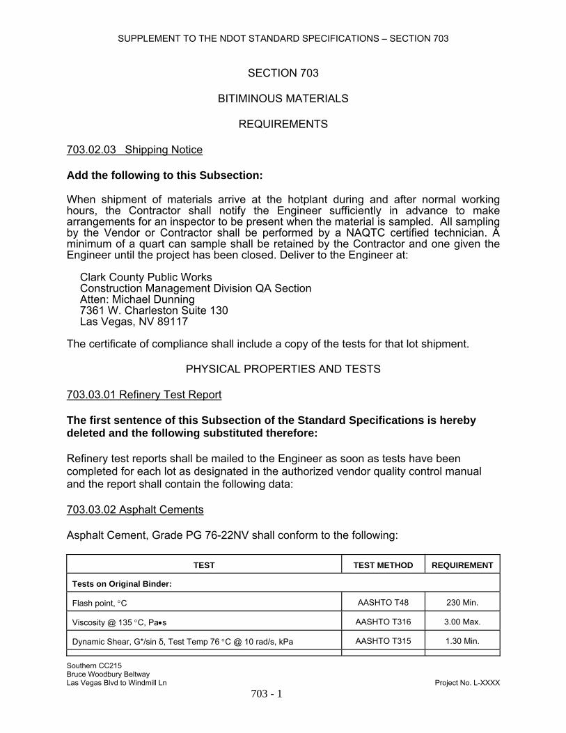
SUPPLEMENT TO THE NDOT STANDARD SPECIFICATIONS – SECTION 703
SECTION 703
BITIMINOUS MATERIALS
REQUIREMENTS 703.02.03 Shipping Notice Add the following to this Subsection: When shipment of materials arrive at the hotplant during and after normal working hours, the Contractor shall notify the Engineer sufficiently in advance to make arrangements for an inspector to be present when the material is sampled. All sampling by the Vendor or Contractor shall be performed by a NAQTC certified technician. A minimum of a quart can sample shall be retained by the Contractor and one given the Engineer until the project has been closed. Deliver to the Engineer at: Clark County Public Works Construction Management Division QA Section Atten: Michael Dunning 7361 W. Charleston Suite 130 Las Vegas, NV 89117 The certificate of compliance shall include a copy of the tests for that lot shipment.
PHYSICAL PROPERTIES AND TESTS
703.03.01 Refinery Test Report The first sentence of this Subsection of the Standard Specifications is hereby deleted and the following substituted therefore: Refinery test reports shall be mailed to the Engineer as soon as tests have been completed for each lot as designated in the authorized vendor quality control manual and the report shall contain the following data: 703.03.02 Asphalt Cements Asphalt Cement, Grade PG 76-22NV shall conform to the following:
TEST
TEST METHOD REQUIREMENT
Tests on Original Binder: Flash point, °C
AASHTO T48
230 Min.
Viscosity @ 135 °C, Pa•s
AASHTO T316
3.00 Max.
Dynamic Shear, G*/sin δ, Test Temp 76 °C @ 10 rad/s, kPa
AASHTO T315
1.30 Min.
Southern CC215 Bruce Woodbury Beltway Las Vegas Blvd to Windmill Ln Project No. L-XXXX 703 - 1

SUPPLEMENT TO THE NDOT STANDARD SPECIFICATIONS – SECTION 703
Ductility @ 4 °C, 5 cm/min, cm Nev. T746 20 Min. Sieve, Particulates Retained
Nev. T730
0
Polymer Content, % by mass
(a)
3.0 Min.
Tests on Residue from R.T.F.O., Nev. T728: Mass Loss, %
Nev. T728
0.50 Max.
Dynamic Shear, G*/sin δ, Test Temp 76 °C @ 10 rad/s, kPa
AASHTO T315
2.20 Min.
Ductility @ 4 °C, 5 cm/min, cm
Nev. T746
10 Min.
Tests on Residue from Pressure Aging Vessel, AASHTO R28 @ 110 °C : Dynamic Shear, G*sin δ, Test Temp 31 °C @ 10 rad/s, kPa
AASHTO T315
5000 Max.
Creep Stiffness, S, Test Temp -12 °C @ 60 sec, MPa
AASHTO T313 (b)
300 Max.
Creep Stiffness, m-value, Test Temp -12 °C @ 60 sec
AASHTO T313 (b)
0.300 Min.
Direct Tension, Failure Strain, Test Temp -12 °C @ 1.0 mm/min, %
AASHTO T314 (b)
1.00 Min.
(a) Certificates of compliance provided for the material shall certify that the minimum polymer content is present. (b) If the creep stiffness is below 300 MPa, the direct tension test is not required. If the creep stiffness is between
300 and 600 MPa, the direct tension failure strain can be used in lieu of the creep stiffness requirement. The m-value requirement must be satisfied in both cases.
Blend the PG 76-22NV at the source of supply and deliver as a completed mixture to the job site. Do not transport PG 76-22NV by railroad car. Upon request, furnish a sample of the base asphalt and the polymer used in the production of the PG 76-22NV. Asphalt Cement, Grade PG 76-22NV not conforming to the requirements specified herein will be assessed demerits according to the following schedule. See Subsection 109.02, where demerits will be evaluated for damages sustained by reason of any noncompliance.
TEST LIMIT WITH TOLERANCE
REJECTION LIMIT
DEMERITS
(a) Flash point, °C
222 Min.
163 Min.
21
Viscosity, Pa•s
3.21 Max.
3.50 Max.
21
Dynamic Shear, Original Binder, kPa
1.17 Min.
0.99 Min.
21
Ductility, Original Binder, cm
20 Min.
0
21
Sieve
1
10
21
Polymer Content, %
3.0 Min.
3.0 Min.
21
Southern CC215 Bruce Woodbury Beltway Las Vegas Blvd to Windmill Ln Project No. L-XXXX 703 - 2

SUPPLEMENT TO THE NDOT STANDARD SPECIFICATIONS – SECTION 703
Mass Loss, % 0.50 Max. 0.71 Max. 21 Dynamic Shear, R.T.F.O., kPa
1.98 Min.
1.65 Min.
21
Ductility, R.T.F.O., cm
10 Min.
0
21
Dynamic Shear, P.A.V., kPa
5500 Max.
6250 Max.
21
Creep Stiffness, S, MPa
330 Max.
375 Max.
21
Creep Stiffness, m-value
0.290 Min.
0.245 Min.
21
Direct Tension, Failure Strain, %
0.90 Min.
0.75 Min.
21
(a) Demerits will be assessed on a prorated basis on the difference between the LIMIT WITH TOLERANCE and the
REJECTION LIMIT. The demerit value will be rounded down to the nearest whole demerit.
Southern CC215 Bruce Woodbury Beltway Las Vegas Blvd to Windmill Ln Project No. L-XXXX 703 - 3

SUPPLEMENT TO THE NDOT STANDARD SPECIFICATIONS – SECTION 704
SECTION 704
BASE AGGREGATES
REQUIREMENTS 704.02.03 Plastic Limits This Subsection of the Special Provisions is hereby deleted and the following substituted therefore: When specified, aggregates shall conform to the applicable requirements of the following table:
TABLE I Percentage by Mass* 75 µm (No. 200) Sieve Plasticity Index Maximum 0-3 15 4 12 5 9 6-8 6 9-11 4 12-15 3 *Test Method No. Nev. T206.
Southern CC215 Bruce Woodbury Beltway Las Vegas Blvd to Windmill Ln Project No. L-XXXX 704 - 1

SUPPLEMENT TO THE NDOT STANDARD SPECIFICATIONS – SECTION 705
SECTION 705
AGGREGATES FOR BITUMINOUS COURSES
REQUIREMENTS 705.02.01 General The first sentence of the last paragraph of this Subsection of the Standard Specifications is hereby deleted and the following substituted therefore: Produce Type 2C and Open-Graded plantmix aggregates by screening all natural fines passing the 9.5 mm (3/8 in.) sieve from the coarse aggregate.
PHYSICAL PROPERTIES AND TESTS 705.03.01 Plantmix Bituminous Surface Aggregates The first paragraph and first table on the top of page 496 of the Standard Specifications are hereby deleted and the following substituted therefore: The following requirements shall apply to all Project Control Tests:
PROJECT CONTROL TESTS
TEST METHOD
REQUIREMENTS Sieve Analysis
Nev. T206
Above
Sampling Aggregate
Nev. T200
—
Fractured Faces (Type 3 Plantmix Aggregate)
Nev. T230
35% Min. (a)
1 Fracture Min. Fractured Faces (Type 2 or 2C Plantmix Aggregate)
Nev. T230
80% Min. (a)
2 Fractures Min. Plasticity Index
Nev. T212
10 Max. (a)
(Blending with sand to eliminate plasticity will not be permitted)
Liquid Limit
Nev. T210
35 Max. (a)
Absorption of Coarse Aggregate
Nev. T111
4% Max. (a)
(a) Individual stockpiles before marination. The following requirements shall apply to all mix designs required according to Subsection 401.02.02:
MIX DESIGN TESTS
TEST METHOD
REQUIREMENTS
Sieve Analysis
Nev. T206
Above
Southern CC215 Bruce Woodbury Beltway Las Vegas Blvd to Windmill Ln Project No. L-XXXX 705 - 1
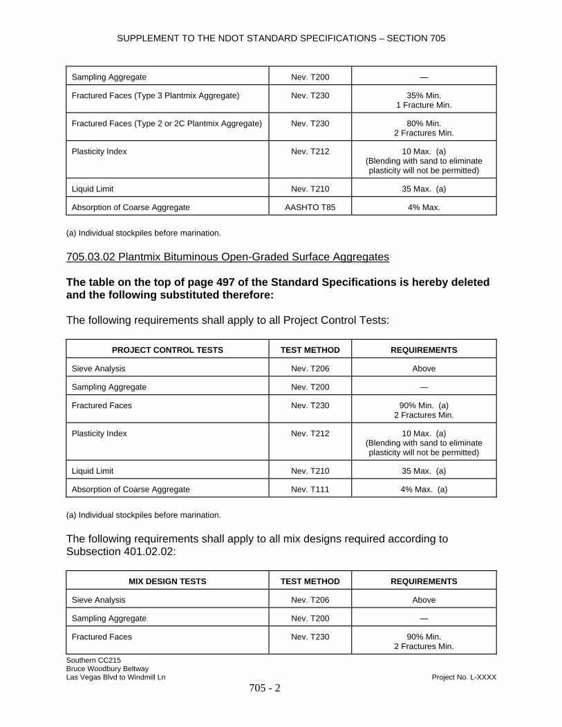
SUPPLEMENT TO THE NDOT STANDARD SPECIFICATIONS – SECTION 705
Sampling Aggregate
Nev. T200
—
Fractured Faces (Type 3 Plantmix Aggregate)
Nev. T230
35% Min.
1 Fracture Min. Fractured Faces (Type 2 or 2C Plantmix Aggregate)
Nev. T230
80% Min.
2 Fractures Min. Plasticity Index
Nev. T212
10 Max. (a)
(Blending with sand to eliminate plasticity will not be permitted)
Liquid Limit
Nev. T210
35 Max. (a)
Absorption of Coarse Aggregate
AASHTO T85
4% Max.
(a) Individual stockpiles before marination. 705.03.02 Plantmix Bituminous Open-Graded Surface Aggregates The table on the top of page 497 of the Standard Specifications is hereby deleted and the following substituted therefore: The following requirements shall apply to all Project Control Tests:
PROJECT CONTROL TESTS
TEST METHOD
REQUIREMENTS Sieve Analysis
Nev. T206
Above
Sampling Aggregate
Nev. T200
—
Fractured Faces
Nev. T230
90% Min. (a)
2 Fractures Min. Plasticity Index
Nev. T212
10 Max. (a)
(Blending with sand to eliminate plasticity will not be permitted)
Liquid Limit
Nev. T210
35 Max. (a)
Absorption of Coarse Aggregate
Nev. T111
4% Max. (a)
(a) Individual stockpiles before marination. The following requirements shall apply to all mix designs required according to Subsection 401.02.02:
MIX DESIGN TESTS
TEST METHOD
REQUIREMENTS
Sieve Analysis
Nev. T206
Above
Sampling Aggregate
Nev. T200
—
Fractured Faces
Nev. T230
90% Min.
2 Fractures Min. Southern CC215 Bruce Woodbury Beltway Las Vegas Blvd to Windmill Ln Project No. L-XXXX 705 - 2
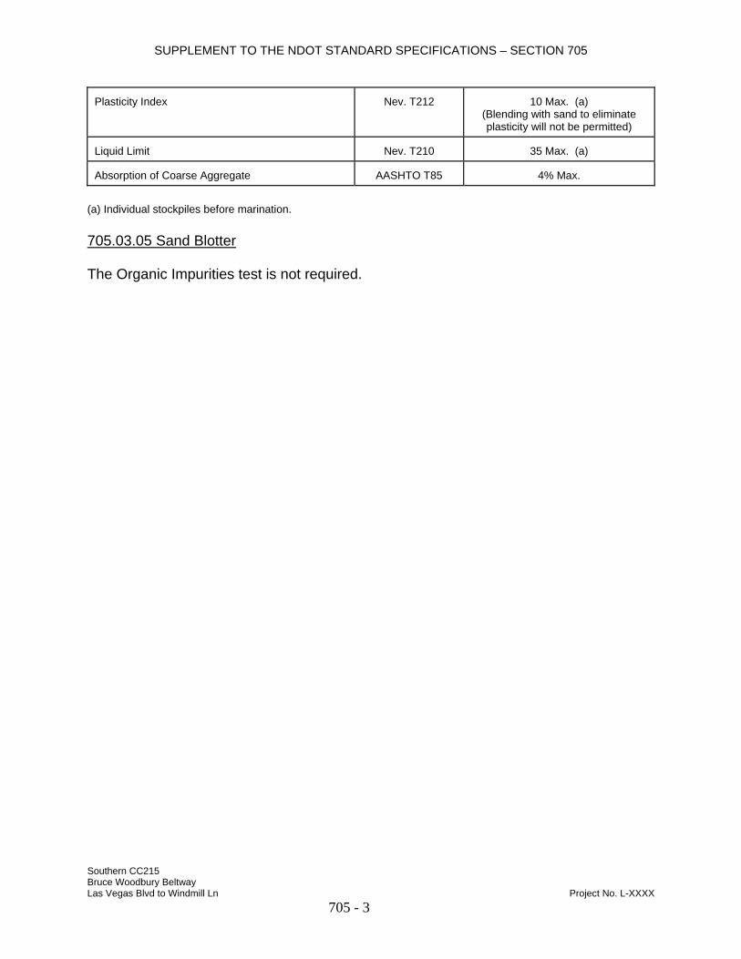
SUPPLEMENT TO THE NDOT STANDARD SPECIFICATIONS – SECTION 705
Plasticity Index
Nev. T212
10 Max. (a)
(Blending with sand to eliminate plasticity will not be permitted)
Liquid Limit
Nev. T210
35 Max. (a)
Absorption of Coarse Aggregate
AASHTO T85
4% Max.
(a) Individual stockpiles before marination. 705.03.05 Sand Blotter The Organic Impurities test is not required.
Southern CC215 Bruce Woodbury Beltway Las Vegas Blvd to Windmill Ln Project No. L-XXXX 705 - 3

SUPPLEMENT TO THE NDOT STANDARD SPECIFICATIONS – SECTION 706
SECTION 706
AGGREGATES FOR PORTLAND CEMENT PRODUCTS
REQUIREMENTS 706.02.01 General The first sentence of the second paragraph of this Subsection of the Standard Specifications is hereby deleted and the following substituted therefore: For mix design approval, the proposed proportions of coarse and fine aggregate, combined mathematically, by volume or mass, shall produce a mixture within the grading limits for combined aggregates as shown in the following table (not applicable to lightweight concrete):
PHYSICAL PROPERTIES AND TESTS 706.03.01 Coarse Aggregate The Cleanness Value, Project Control Test, is not required. 706.03.03 Fine Aggregate The Sand Equivalent, Project Control Test, is not required. 706.03.04 Grout and Mortar Aggregate The test method for Soundness, Fine Aggregate, listed in this Subsection of the Standard Specifications is hereby changed from “Nev. T470" to “AASHTO T104.” 706.03.05 Stone for Riprap The last requirement of the Percent Passing by Mass column in the table on the top of page 505 of the Standard Specifications is hereby changed from "0" to "0-5." 706.03.07 Aggregate for Riprap Bedding The last requirement of the Percent Passing by Mass column for all classes of riprap bedding in the tables on the bottom of page 505 of the Standard Specifications are hereby changed from "0" to "0-5."
Southern CC215 Bruce Woodbury Beltway Las Vegas Blvd to Windmill Ln Project No. L-XXXX 706 - 1
SUPPLEMENT TO THE NDOT STANDARD SPECIFICATIONS – SECTION 716
SECTION 716
SIGN MATERIAL
PHYSICAL PROPERTIES AND TESTS 716.03.01 Reflective Sheeting Subparagraph “(d)” of this Subsection of the Standard Specifications is hereby deleted and the following substituted therefore: (d) NDOT Type VI. A high intensity sheeting. A fluorescent orange wide angle
microprismatic retroreflective sheeting material used for roll-up signs.
NDOT Type VI reflective sheeting shall conform to the properties of Type VI sheeting as specified in ASTM D4956.
Use NDOT Type VI sheeting listed in the QPL.
Subparagraph “(e)” of this Subsection of the Standard Specifications is hereby deleted and the following substituted therefore: (e) NDOT Type X. A high intensity fluorescent sheeting. An unmetallized
microprismatic retroreflective element material.
NDOT Type X reflective sheeting shall conform to the properties of Type VII, Type VIII, or Type IX sheeting as specified in ASTM D4956 with the following exception:
The requirement to meet the minimum coefficient of retroreflection for 1.0° observation angle is hereby waived.
Use NDOT Type X sheeting listed in the QPL.
716.03.04 Overhead Sign Structures and Sign Frames Subparagraph "(j)" on page 527 of the Standard Specifications is hereby deleted and the following substituted therefore: (j) Perform fabrication and welding according to the requirements of this Subsection
and Section 506 with the following exception; use the AWS Structural Welding Code - Steel D1.1 in lieu of the AWS Bridge Welding Code D1.5.
Southern CC215 Bruce Woodbury Beltway Las Vegas Blvd to Windmill Ln Project No. L-XXXX 716 - 1
SUPPLEMENT TO THE NDOT STANDARD SPECIFICATIONS – SECTION 720
SECTION 720
GUARDRAIL MATERIALS
PHYSICAL PROPERTIES AND TESTS 720.03.04 Metal Guardrail Posts This Subsection of the Standard Specifications is hereby deleted and the following substituted therefore: Metal posts shall be of structural steel conforming to ASTM A36 and galvanized according to AASHTO M111.
Southern CC215 Bruce Woodbury Beltway Las Vegas Blvd to Windmill Ln Project No. L-XXXX 720 - 1
SUPPLEMENT TO THE NDOT STANDARD SPECIFICATIONS – SECTION 725
SECTION 725
ELASTOMERIC BEARING PADS
PHYSICAL PROPERTIES AND TESTS 725.03.01 General The maximum design compressive load is 1000 psi unless shown otherwise on the plans.
Southern CC215 Bruce Woodbury Beltway Las Vegas Blvd to Windmill Ln Project No. L-XXXX 725 - 1

SUPPLEMENT TO THE NDOT STANDARD SPECIFICATIONS – SECTION 730
SECTION 730
TRAFFIC BEADS
PHYSICAL PROPERTIES AND TESTS 730.02.01 Requirements (b) Glass Beads for Waterborne Paint. The moisture content of the beads shall not
exceed 0.01% by mass when tested at 105 °C for 3 hours. The third paragraph on page 564 of the Standard Specifications is hereby deleted and the following substituted therefore: Use Type A glass beads for Type I and Type II waterborne paints.
Southern CC215 Bruce Woodbury Beltway Las Vegas Blvd to Windmill Ln Project No. L-XXXX 730 - 1

SUPPLEMENT TO THE NDOT STANDARD SPECIFICATIONS – SECTION 732
SECTION 732
PAVEMENT MARKING FILM
PHYSICAL PROPERTIES AND TESTS 732.03.02 Pavement Marking Tape (Type 2) This Subsection of the Standard Specifications is hereby deleted and the following substituted therefore: Type 2 marking tape shall conform to ASTM D4505; Reflectivity Level II; Adhesive Class 1, 2, or 3; Skid Resistance Level B. Use Type 2 pavement marking tape listed in the QPL. 732.03.04 Thermoplastic (a) Hot Applied Thermoplastic. Use hot applied thermoplastic listed in the QPL.
Southern CC215 Bruce Woodbury Beltway Las Vegas Blvd to Windmill Ln Project No. L-XXXX 732 - 1