Embed Size (px)
Citation preview
REVISIONS
For Table of Revisions,
see Sheet 2.
COMMONWEALTH OF VIRGINIA
DEPARTMENT OF TRANSPORTATION
No. Description DateCOORDINATED:
SUPERVISED:
DESIGNED:
DRAWN:
CHECKED:
PLANS BY:
GENERAL NOTES:
ROUTE
FEDERAL AID
PROJECT ROUTE PROJECT
STATE SHEET
NO.
and Scour Code:
FHWA Construction
UPC No.
DESIGN EXCEPTION(S):
VA.
STATE
Federal Oversight Code:
NBIS Number:
cDate:
b29685001.d
gn
STRUCTURAL ENGINEER
RICHMOND, VA
MOFFATT & NICHOL
Nicholas E. Smilek
T. Michael Harris
Consultant
None.
296-85
L
ABUTMENT A ABUTMENT B
PLAN
Face of rail
Face of rail
ORIGINAL SIGNATURES ON TITLE SHEET OF ROAD PLANS
oN 67 -50'-43" E
1
90176
158 0158-097-800, B644
X080-S5
000000000030587
NFO
BR-097-1()
2016, Commonwealth of Virginia
CR
EE
KT
OM
S
L
46'-0"18'-
2"
18'-
0"
46'-0"
Abutment B
Sta. 102+30.05
Abutment A
Sta. 101+84.05
End of slab End of slab
DEVELOPED SECTION ALONG CONSTR. BL
Rte. 158 Constr. B
Existing profile along
Elev. 1986.83 Elev. 1987.00
To Norton
To Saint Paul
+0.44% +0.33%
C.G. Sta. 102+00.00
C.G. Elev. 1986.90
V.C. = 20.00'
Finished gradeFinished grade
Approach slab
Approach slab
April 1977
El. 1988.6
High Water
Sheet 1 of 25_ _ _ _ _ _ _ _ _ _
(to be removed)
Existing structures
1
1•
1
1•
Normal to abutment PROJ. 0158-097-800, B644
WISE CO. - 0.4 MI. E. ALT. ROUTE 58
OVER TOMS CREEK
ROUTE 158 (EAST FRONT STREET)
PROPOSED BRIDGE ON
Existing structure
curb
sidewalk
Face of 42'-
4"
Date
Approved:
Recommended for Approval:
_ _ _ _ _ _ _ _ _ _ _ _ _ _ _ _ _ _ _ _ _ _ _ _ _ _ _ _ _ _ _ _ _ _ _ _
Date
_ _ _ _ _ _ _ _ _ _ _ _ _ _ _ _ _ _ _ _ _ _ _ _ _ _ _ _
District Engineer
Date
Recommended for Approval: _ _ _ _ _ _ _ _ _ _ _ _ _ _ _ _ _ _ _ _ _ _ _ _ _ _ _ _
District Planning and Investment Manager
District Project Development Engineer
Date
Scale: „" = 1'-0"
Dry riprap cl. II, typ.
Scott R. Canfield
Constr. B
Rte. 158
high water
at ordinary
Edge of Stream
high water
at ordinary
Edge of Stream
Toe of fill
20'-
0"
15'-
0"
Dry riprap cl. II, typ.
20'-
0"
Cut Cut
El. 1972.0
High Water
Ordinary
Sta. 101+84.05
End of slab
Beginning of bridge
Sta. 102+30.05
End of slab
End of bridge
HR-1, Type II, typ.
Pedestrian handrail
Terry W. Coker
(to be modified)
Existing wooden deck
in the road plans)
removed (see D-900
wooden deck to be
Portion of existing
James R. Jones
to meet wingwall)
wall (partially demolish
Existing CMU retaining
April 15, 2016
and cofferdams.
temporary shoring
See sheet 3 for
Note:
10"
10"
6'-
2"
(Continued on sheet 2)
strands conforming to ASTM A416 Grade 270.
Prestressing strands shall be uncoated, seven-wire, low-relaxation steel
Class III, may be substituted for Class II.
may be substituted for Class I. Corrosion Resistant Reinforcing Steel,
steel schedule. Corrosion Resistant Reinforcing Steel, Class II or Class III,
required on this project is noted on plan sheets and in the reinforcing
stainless clad steel or solid stainless steel. The Class of CRR steel
strength shall be: 100 ksi for low carbon/chromium steel and 60 ksi for
of the three Classes listed in the special provision. The minimum yield
Corrosion resistant reinforcing (CRR) steels shall conform to one or more
to fabrication and construction tolerances.
are to centers of bars except where otherwise noted and are subject
special provisions. All reinforcing bar dimensions on the detailed drawings
reinforcing) which shall conform to applicable specifications noted in the
Grade 60 except for reinforcing steels noted as CRR (corrosion resistant
All reinforcing steel shall be deformed and shall conform to ASTM A615,
equal to 4000 psi.
minimum compressive cylinder strength at time of release of strands
compressive cylinder strength at 28 days equal to 5000 psi and a
Prestressed concrete in slabs shall be Class A5 having a minimum
Class A4 Modified; in substructure, Class A3.
Concrete in deck slab, rails, and terminal walls shall be Low Shrinkage
Design loading includes 15 psf allowance for future wearing surface.
construction methods.
Design loading includes 10 psf allowance for construction tolerances and
Specifications and Special Provisions included in the contract documents.
These plans are incomplete unless accompanied by the Supplemental
Bridge Standards, 2008
Standards: Virginia Department of Transportation Road and
2014 and VDOT Modifications.
Design: AASHTO LRFD Bridge Design Specifications, 7th Edition,
Bridge Specifications, 2016.
Construction: Virginia Department of Transportation Road and
Specifications:
Drainage area: 10.6 sq. mi.
Capacity: HL-93 loading
Span layout: 1-46'-0" prestressed concrete voided slab span.
Width: 42'-4" face-to-face of rails.
the applicable laws.
signatures is illegal. Violators will be prosecuted to the full extent of
VDOT Central Office. Any misuse of electronic files, including scanned
The original approved sheet, including original signatures, is filed in the
15'-
0"
C
plans
see roadway
sewer line,
sanitary
L relocated
plans.
sheets in roadway
B only). See utility
sewer line (Abutment
Relocated sanitary
Matthew B. Cox 4-26-16
4-26-16
4-26-16Randy Hamilton
Dennis R. Harris
Date Plan No. Sheet No.Designed: ...........
Drawn: ................
Checked: ............2016, Commonwealth of Virginiac
No. Description Date
STRUCTURE AND BRIDGE DIVISION
COMMONWEALTH OF VIRGINIA
DEPARTMENT OF TRANSPORTATION
Revisions
ROUTE
FEDERAL AID
PROJECT ROUTE PROJECT
STATE SHEET
NO.
VA.
STATEROUTE
FEDERAL AID
PROJECT ROUTE PROJECT
STATE SHEET
NO.
VA.
STATE
b29685002.d
gn
STRUCTURAL ENGINEER
RICHMOND, VA
MOFFATT & NICHOL
296-85
2
2 of 25
158 0158-097-800, B644
accordance with current Road and Bridge Specifications.
Denotes items to be paid for on the basis of plan quantities in
LUMP SUM BID ITEMS
Mobilization
Construction Surveying
LS
LS
LS
LS
Units Quantity
CY
LB
EA
LF
ESTIMATED QUANTITIES - SUPERSTRUCTURE ONLY
CY
Item
Sheet No.
INDEX OF SHEETS
Description
DateSheets RevisedRev. No.
TABLE OF REVISIONS
AND INDEX OF SHEETS
ESTIMATED QUANTITIES
Corrosion Resistant Reinf. Steel, Class II
11
46
Prestressed Concrete Slab 4'x21" x (+45'-50')
Title sheet: plan, profile, design exceptions
and general notes
Estimated quantities and index of sheets
Superstructure
Superstructure
Deck slab plan and elevations
accordance with current Road and Bridge Specifications.
Denotes items to be paid for on the basis of plan quantities in
accordance with current Road and Bridge Specifications.
Denotes items to be paid for on the basis of plan quantities in
Footing
Neat
Abutment A
Abutment B
Footing
Neat
Total
CY
ESTIMATED QUANTITIES - SUBSTRUCTURE ONLY
Class A3
Concrete
LB
Steel
Reinforcing
LB
Class I
Reinf. Steel,
Resistant
Corrosion
CY
Excav.
Struct.
Min. CBR-30
Type I
Select Matl.
TON
Wall Drain
Geocomposite
SY TON EA
Cofferdam
Structure (Str. No. 1029)
Dismantle and Remove Existing
GENERAL NOTES:
Abutment A plan, elevation and section
Abutment B plan, elevation and section
Reinforcing steel schedule
Reinforcing steel schedule
Engineering geology
Engineering geology
Engineering geology
Engineering geology
Engineering geology
Railing, BR27D, 2 rails
Concrete Class A4 Bridge Approach Slab
SY
LF
6"
Underdrain
Pipe
LSLF
46Railing, BR27D, 3 rails
Substructure layout
42"-BR27D steel railing
54"-BR27D steel railing
BR27D rail connections and notes
Approach slabs
SRC
TPA
42" BR27C/BR27D terminal wall
54" BR27C/BR27D terminal wall
2
1
Apr. 2016
sub-footing.
approved by the Engineer. See sheets 4 and 6 for section of
Contractor is only to be paid for this item if the sub-footing is
may be necessary if foundation bearing is lower than shown on plans.
Quantity shown is for an assumed 2ft depth of sub-footing which
CY
Class B2
Concrete
25
24
23
22
21
20
19
18
17
16
15
14
13
12
11
10
9
8
7
6
5
4
3
2
1
YJZ
LS
Abutment A footing plan and wingwall elevations
Abutment B footing plan and wingwall elevations
38"
Class II
Riprap
Dry
Wingwall sections
LS
Reinforcing Steel Bridge Approach Slab LB
60.5
66.8
10,880
216Bridge Deck Grooving
Modify Existing Structure
3
80.1
Bearing and waterproofing details for concrete overlay
70.4
77.1
70.4
51.2
51.2
445
449
894
765
775
1540 195
CY
Backfill
Porous
298.0 102.4
2 95
BR-097-1()
Protection (Pedestrian Bridge)
Environmental and Worker
(Pedestrian Bridge, Type B)
Material Disposal
7280
7270
641
690
1331
7510
7330
1484014550
78
72
150
5910
road plan summary sheet.
Quantity of pedestrian handrail on abutment wingwalls is included in the
corner of the end of curbing.
the back of sidewalk and curbing and 11.50' northeast of the back
west of a yield sign, 30.80' southwest of the intersection point of
intersection of W. Front Street and 2nd Street SW. It is located 11.95'
ground. The monument is located at the southwest corner of the
VDOT Monument Stamped 198-0006 set in concrete flush with B.M.:
(Str. No. 1029).
be included in price bid for Dismantle and Remove Existing Structure
accordance with Sec. 411. Demolition of existing pedestrian bridge shall
The existing pedestrian bridge is designated a Type B Structure in
Bridge No. of existing bridge is 1029. Plan No. is 27-02.
Existing Structure.
and construction shall be included in the lump sum price bid for Modify
associated with the modification of the wooden deck including design
sealed by an engineer licensed in the Commonwealth of Virginia. All costs
approval showing proposed deck modifications and shall be signed and
deck. Plans and calculations shall be submitted by the Contractor for
shall be constructed of similar materials and methods as the existing
permanent shoring, support columns, beams and decking. Modifications
in the road plans. Work will include, but is not limited to, installation of
structure to support pedestrian loads within the easement lines shown
modifications to the wooden deck as necessary to strengthen the
railing and structure. The Contractor will also be required to make
end railing at the demolition line and sufficiently tie into the existing
and the area behind the building. The Contractor shall construct an
construction, the Contractor shall maintain access to the wooden deck
required to continue to serve as access for the property owner. During
plans. The remaining portion of the wooden deck shall be modified as
bridge shall be partially demolished in accordance with D-900 in the road
The existing wooden deck located in the southwest quadrant of the
to this fact as it may affect the excavation.
of what is believed to be a concrete slab. The contractor is alerted
of the bridge were started and then abandoned due to the presence
During the geotechnical exploration, several borings on the east side
inches.
service limit state loading has been calculated to be less than 0.35
considers a resistance factor of 0.45. The settlement under the
limit state load of 6.8 ksf. The strength limit state bearing resistance
factored bearing resistance of 9.0 ksf and a maximum factored service
Footings for abutments have been designed for a strength limit state
also not be excessively wet prior to placement of concrete.
weathered or loose rock before placing concrete. The surface should
geomaterials (IGM). The bearing surface should be clean and free of
The footings shall bear on very hard or very dense intermediate
bridge for purpose of demolition.
pier of existing bridge (Str. No. 1029) and existing pedestrian
Pay item for cofferdam for Abutment A includes cofferdam around
Temporary Shoring
LFECC for Shear Keys460
Low Shrinkage Class A4 Modified Concrete
1002
4
L
oN 67 -50'-43" E
Abutment B
Sta. 102+30.05
Abutment A
Sta. 101+84.05
End of slab End of slab
To Norton
To Saint Paul
Dry riprap cl. II, typ.
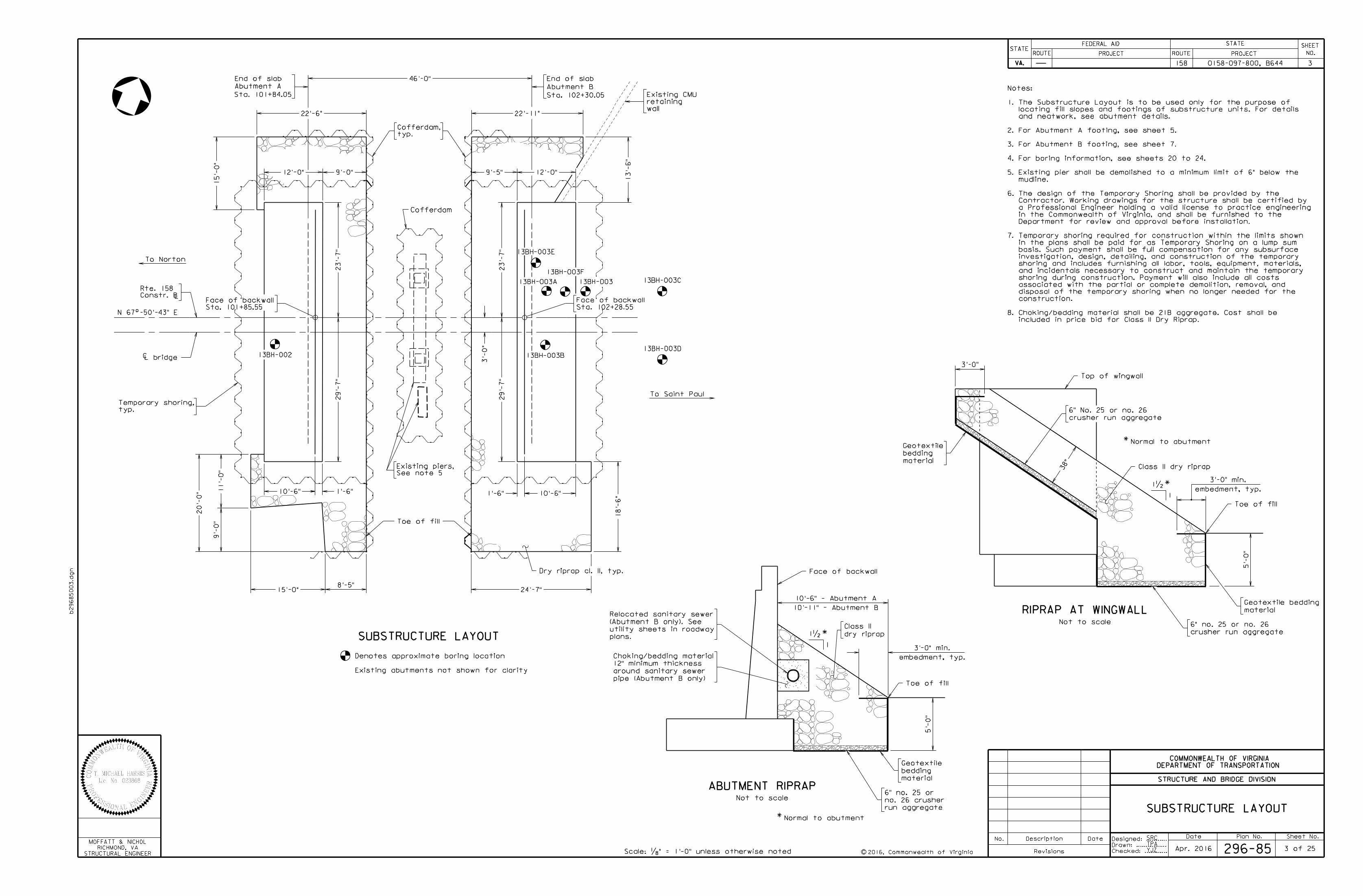
SUBSTRUCTURE LAYOUT
Date Plan No. Sheet No.Designed: ...........
Drawn: ................
Checked: ............c
No. Description Date
STRUCTURE AND BRIDGE DIVISION
COMMONWEALTH OF VIRGINIA
DEPARTMENT OF TRANSPORTATION
Revisions
ROUTE
FEDERAL AID
PROJECT ROUTE PROJECT
STATE SHEET
NO.
VA.
STATEROUTE
FEDERAL AID
PROJECT ROUTE PROJECT
STATE SHEET
NO.
VA.
STATE
b29685003.d
gn
STRUCTURAL ENGINEER
RICHMOND, VA
MOFFATT & NICHOL
296-85
0158-097-800, B644158
Scale: „" = 1'-0" unless otherwise noted
SRC
TPA3 of 25
SUBSTRUCTURE LAYOUT
3
Denotes approximate boring location
13BH-003B
13BH-003A
13BH-003E
13BH-003
1
1•
Normal to abutment
ABUTMENT RIPRAPNot to scale
13BH-003C
13BH-003D
Sta. 102+28.55
Face of backwall
Sta. 101+85.55
Face of backwallConstr. B
Rte. 158
typ.
Cofferdam,
Toe of fill
20'-
0" 1
1'-
0"
15'-0"
29'-
7"
23'-
7"
23'-
7"
29'-
7"
Existing abutments not shown for clarity
Cofferdam
Apr. 2016
10'-6" 10'-6"1'-6" 1'-6"
12'-0"
46'-0"
12'-0"
13'-
6"
9'-
0"
YJZ
13BH-002
13BH-003F
3'-
0"
L bridgeC
wall
retaining
Existing CMU
Toe of fill
5'-
0"
embedment, typ.
3'-0" min.
Face of backwall
dry riprap
Class II
typ.
Temporary shoring,
24'-7"
9'-5"
22'-11"22'-6"
9'-0"
8'-5"
18'-
6"
Class II dry riprap
Normal to abutment
Not to scale
Toe of fill
crusher run aggregate
6" no. 25 or no. 26
material
Geotextile bedding
RIPRAP AT WINGWALL
Top of wingwall
crusher run aggregate
6" No. 25 or no. 26
material
bedding
Geotextile
38"
material
bedding
Geotextile
run aggregate
no. 26 crusher
6" no. 25 or
2016, Commonwealth of Virginia
1
1•
5'-
0"
3'-0" min.
embedment, typ.
3'-0"
See note 5
Existing piers,
10'-11" - Abutment B
10'-6" - Abutment A
included in price bid for Class II Dry Riprap.
Choking/bedding material shall be 21B aggregate. Cost shall be
construction.
disposal of the temporary shoring when no longer needed for the
associated with the partial or complete demolition, removal, and
shoring during construction. Payment will also include all costs
and incidentals necessary to construct and maintain the temporary
shoring and includes furnishing all labor, tools, equipment, materials,
investigation, design, detailing, and construction of the temporary
basis. Such payment shall be full compensation for any subsurface
in the plans shall be paid for as Temporary Shoring on a lump sum
Temporary shoring required for construction within the limits shown
Department for review and approval before installation.
in the Commonwealth of Virginia, and shall be furnished to the
a Professional Engineer holding a valid license to practice engineering
Contractor. Working drawings for the structure shall be certified by
The design of the Temporary Shoring shall be provided by the
mudline.
Existing pier shall be demolished to a minimum limit of 6" below the
For boring information, see sheets 20 to 24.
For Abutment B footing, see sheet 7.
For Abutment A footing, see sheet 5.
and neatwork, see abutment details.
locating fill slopes and footings of substructure units. For details
The Substructure Layout is to be used only for the purpose of
8.
7.
6.
5.
4.
3.
2.
1.
Notes:
pipe (Abutment B only)
around sanitary sewer
12" minimum thickness
Choking/bedding material
15'-
0"
plans.
utility sheets in roadway
(Abutment B only). See
Relocated sanitary sewer
Date Plan No. Sheet No.Designed: ...........
Drawn: ................
Checked: ............c
No. Description Date
STRUCTURE AND BRIDGE DIVISION
COMMONWEALTH OF VIRGINIA
DEPARTMENT OF TRANSPORTATION
Revisions
ROUTE
FEDERAL AID
PROJECT ROUTE PROJECT
STATE SHEET
NO.
VA.
STATEROUTE
FEDERAL AID
PROJECT ROUTE PROJECT
STATE SHEET
NO.
VA.
STATE
b29685004.d
gn
STRUCTURAL ENGINEER
RICHMOND, VA
MOFFATT & NICHOL
0158-097-800, B644158
Scale: ‚" = 1'-0" unless otherwise noted 296-85
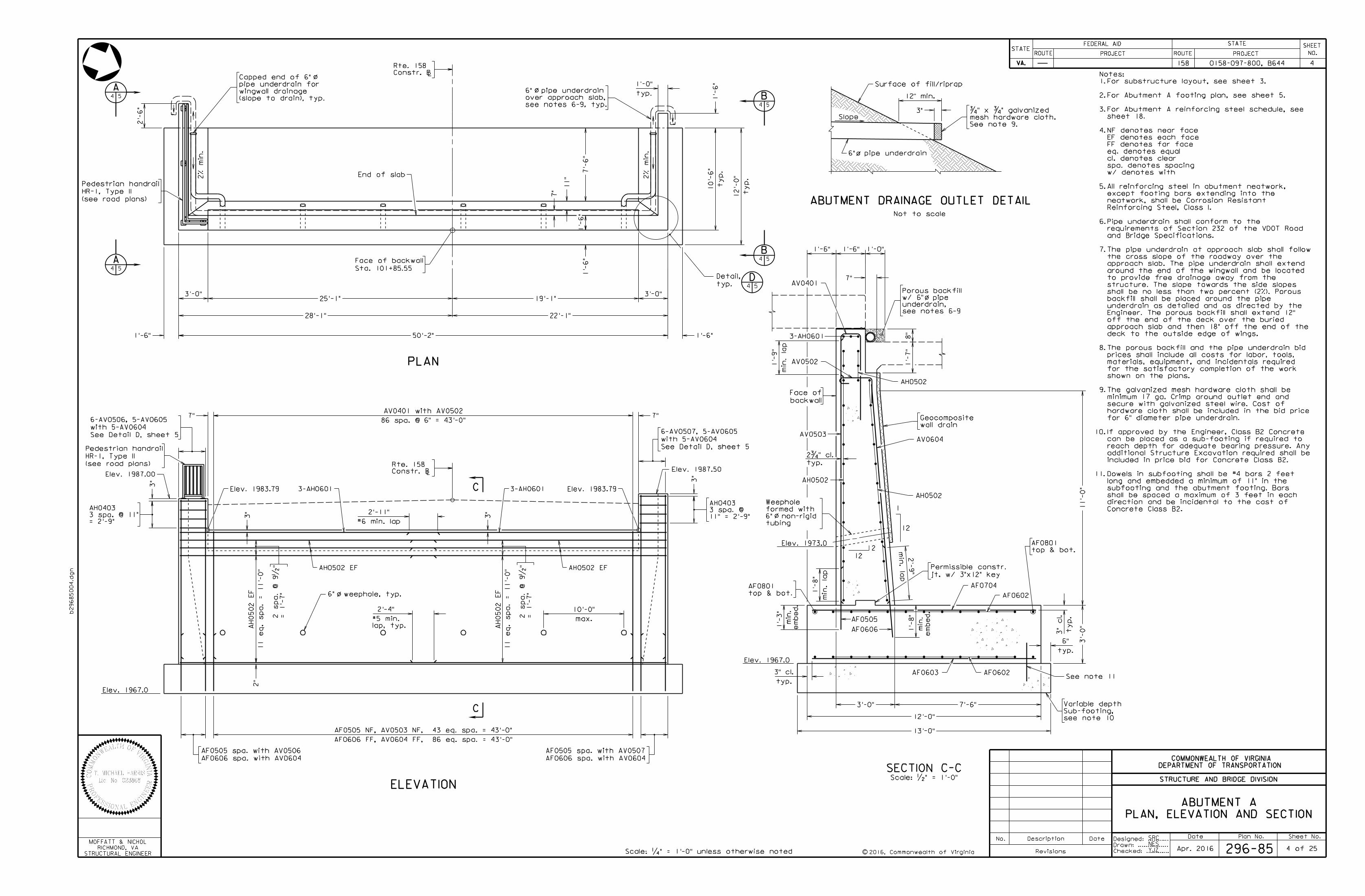
PLAN, ELEVATION AND SECTION
ABUTMENT A
4
SECTION C-CScale: •" = 1'-0"
PLAN
ELEVATION
1'-
6"
C
C
L
SRC
NES4 of 25
wall drain
Geocomposite
8"
1'-
7"
o/
1'-0"
2016, Commonwealth of Virginia
19'-1"25'-1"
A4 5 B
4 5
B4 5A
4 5
2'-
6"
ty
p.
10'-
6"
ty
p.
12'-
0"End of slab
Sta. 101+85.55
Face of backwall
1
12
1'-
6"
typ.
1'-0"
1'-
6"
7'-
6"
3'-0"
1'-6"
3'-0"
1'-6"
22'-1"28'-1"
50'-2"
7"
11"
1'-6"
7"
7'-6"3'-0"
jt. w/ 3"x12" key
Permissible constr.
AH0502
AV0604AV0503
AH0502
1'-
3"
AF0602
AF0704
11'-
0"
3'-
0"
min. la
p
1'-
8"
top & bot.
AF0801
AF0602
12'-0"
AF0603
top & bot.
AF0801
AV0401
AV0502
1'-6"
Apr. 2016
Elev. 1967.0
D4 5
13'-0"
typ.
6"
3-AH0601
1'-
8"
AF0505
AF0606
min. la
p
2'-
9"
2%
min.
Constr. B
Rte. 158 typ.
2ƒ" cl.
min. la
p
1'-
9"
typ.
3" cl.
YJZ
AH0502
3-AH0601 3-AH0601
Elev. 1967.0
= 2'-9"
3 spa. @ 11"
AH0403
AF0606 spa. with AV0604
AF0505 spa. with AV0507
AF0606 spa. with AV0604
AF0505 spa. with AV0506
#6 min. lap
2'-11"
86 spa. @ 6" = 43'-0"
AV0401 with AV0502
Elev. 1987.00Elev. 1987.50
7" 7"
See Detail D, sheet 5
with 5-AV0604
6-AV0506, 5-AV0605
See Detail D, sheet 5
with 5-AV0604
6-AV0507, 5-AV0605
3"
3"
LConstr. B
Rte. 158
o/
ty
p.
3"
cl.
em
bed.
min.
em
bed.
min.
2%
min.
2
12
o/
max.
10'-0"
Elev. 1983.79Elev. 1983.79
11 e
q.
spa.
= 11'-
0"
AH0502
EF
11 e
q.
spa.
= 11'-
0"
AH0502
EF
AF0606 FF, AV0604 FF, 86 eq. spa. = 43'-0"
AF0505 NF, AV0503 NF, 43 eq. spa. = 43'-0"
o/6" weephole, typ.
AH0502 EF AH0502 EF
= 1'-
7"
2 spa.
@ 9•
"
#5 min.
2'-4"
lap, typ.
(see road plans)
HR-1, Type II
Pedestrian handrail
(see road plans)
HR-1, Type II
Pedestrian handrail
Elev. 1973.0
2"
(slope to drain), typ.
wingwall drainage
pipe underdrain for
Capped end of 6"
typ.
Detail,
see notes 6-9
underdrain,
w/ 6" pipe
Porous backfill
see note 10
Sub-footing,
Variable depth
11.
10.
9.
8.
7.
6.
5.
4.
3.
2.
1.
Notes:
tubing
6" non-rigid
formed with
Weephole
backwall
Face of
11" = 2'-9"
3 spa. @
AH0403
See note 11
3"
12" min.
Slope
See note 9.
mesh hardware cloth.
ƒ" x ƒ" galvanized
6" pipe underdrain
o/
Not to scale
ABUTMENT DRAINAGE OUTLET DETAIL
Surface of fill/riprapo/
see notes 6-9, typ.
over approach slab,
6" pipe underdrain
3"
= 1'-
7"
2 spa.
@ 9•
"
3" Concrete Class B2.
direction and be incidental to the cast of
shall be spaced a maximum of 3 feet in each
subfooting and the abutment footing. Bars
long and embedded a minimum of 11" in the
Dowels in subfooting shall be #4 bars 2 feet
included in price bid for Concrete Class B2.
additional Structure Excavation required shall be
reach depth for adequate bearing pressure. Any
can be placed as a sub-footing if required to
If approved by the Engineer, Class B2 Concrete
for 6" diameter pipe underdrain.
hardware cloth shall be included in the bid price
secure with galvanized steel wire. Cost of
minimum 17 ga. Crimp around outlet end and
The galvanized mesh hardware cloth shall be
shown on the plans.
for the satisfactory completion of the work
materials, equipment, and incidentals required
prices shall include all costs for labor, tools,
The porous backfill and the pipe underdrain bid
deck to the outside edge of wings.
approach slab and then 18" off the end of the
off the end of the deck over the buried
Engineer. The porous backfill shall extend 12"
underdrain as detailed and as directed by the
backfill shall be placed around the pipe
shall be no less than two percent (2%). Porous
structure. The slope towards the side slopes
to provide free drainage away from the
around the end of the wingwall and be located
approach slab. The pipe underdrain shall extend
the cross slope of the roadway over the
The pipe underdrain at approach slab shall follow
and Bridge Specifications.
requirements of Section 232 of the VDOT Road
Pipe underdrain shall conform to the
Reinforcing Steel, Class I.
neatwork, shall be Corrosion Resistant
except footing bars extending into the
All reinforcing steel in abutment neatwork,
w/ denotes with
spa. denotes spacing
cl. denotes clear
eq. denotes equal
FF denotes far face
EF denotes each face
NF denotes near face
sheet 18.
For Abutment A reinforcing steel schedule, see
For Abutment A footing plan, see sheet 5.
For substructure layout, see sheet 3.
Date Plan No. Sheet No.Designed: ...........
Drawn: ................
Checked: ............c
No. Description Date
STRUCTURE AND BRIDGE DIVISION
COMMONWEALTH OF VIRGINIA
DEPARTMENT OF TRANSPORTATION
Revisions
ROUTE
FEDERAL AID
PROJECT ROUTE PROJECT
STATE SHEET
NO.
VA.
STATEROUTE
FEDERAL AID
PROJECT ROUTE PROJECT
STATE SHEET
NO.
VA.
STATE
b29685005.d
gn
STRUCTURAL ENGINEER
RICHMOND, VA
MOFFATT & NICHOL
0158-097-800, B644158
Scale: ‚" = 1'-0" unless otherwise noted 296-85
5
L
53'-2"
SRC
NES5 of 25
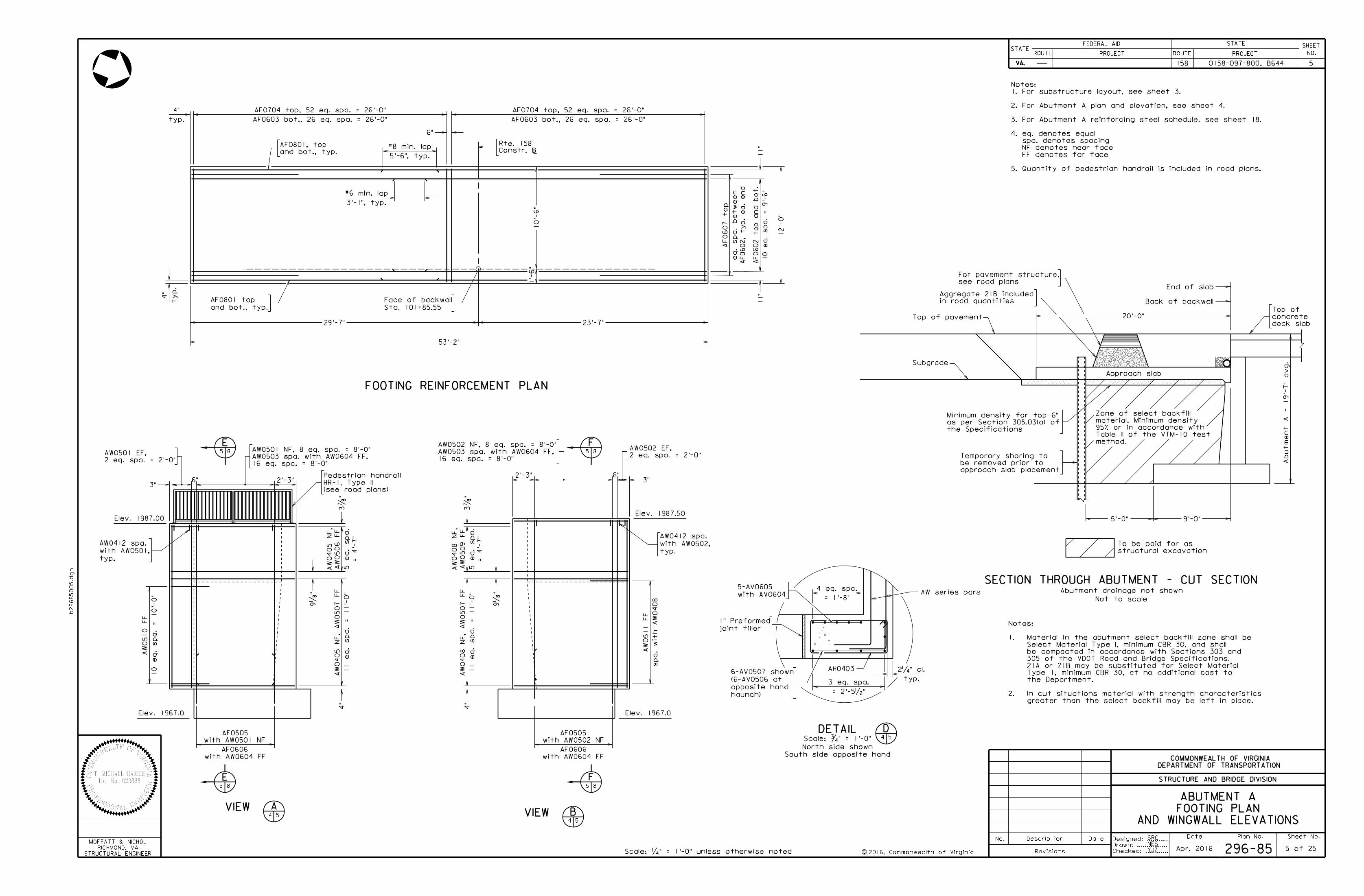
FOOTING REINFORCEMENT PLAN
and bot., typ.
AF0801, top
2016, Commonwealth of Virginia
the Specifications
as per Section 305.03(a) of
Minimum density for top 6"
Back of backwall
20'-0"
Subgrade
Approach slab
Top of pavement
Not to scale
Abutment drainage not shown
SECTION THROUGH ABUTMENT - CUT SECTION
structural excavation
To be paid for as
9'-0"5'-0"
Sta. 101+85.55
Face of backwall
and bot., typ.
AF0801 top
Apr. 2016
Abut
me
nt
A - 19'-
7"
avg.
Constr. B
Rte. 158
YJZ
AW series bars
AH0403
method.
Table II of the VTM-10 test
95% or in accordance with
material. Minimum density
Zone of select backfill
DETAIL D54
23'-7"29'-7"
typ.
2‚" cl.
Scale: ƒ" = 1'-0"
with AV0604
5-AV0605
= 1'-8"
4 eq. spa.
= 2'-5•"
3 eq. spa.
Elev. 1967.0Elev. 1967.0
VIEW A4 VIEW B
4
Elev. 1987.50
6"
Elev. 1987.00
AF0603 bot., 26 eq. spa. = 26'-0"
AF0704 top, 52 eq. spa. = 26'-0"
AF0603 bot., 26 eq. spa. = 26'-0"
AF0704 top, 52 eq. spa. = 26'-0"
6"
End of slab
AND WINGWALL ELEVATIONS
FOOTING PLAN
ABUTMENT A
5 8
5 8 8
85
5
F
FE
E
55
2'-3"3"
1'-
6"
10'-
6"
ty
p.
4"
12'-
0"
AF0602, typ.
ea.
end
11"
10 eq.
spa.
= 9'-
6"
AF0602 top and bot.
11"
5'-6", typ.
#8 min. lap
3'-1", typ.
#6 min. lap
typ.
4"
deck slab
concrete
Top of
haunch)
opposite hand
(6-AV0506 at
6-AV0507 shown
2 eq. spa. = 2'-0"
AW0501 EF,
3‡
"11 e
q.
spa.
= 11'-
0"
AW
0405
NF,
AW
0507
FF
4"
9„
"
AF0505
AW
0405
NF,
= 4'-
7"
5 e
q.
spa.
AW
0506
FF
2'-3" 6"
2 eq. spa. = 2'-0"
AW0502 EF,
3‡
"11 e
q.
spa.
= 11'-
0"
AW
0408
NF,
AW
0507
FF
5 e
q.
spa.
AW
0509
FF
9„
"
3"= 4'-
7"
AW
0408
NF,
AF0505
4"
eq.
spa.
bet
wee
n
AF0607 to
p
AF0606
with AW0502 NF
with AW0604 FF
10 e
q.
spa.
= 10'-
0"
AW
0510
FF
16 eq. spa. = 8'-0"
AW0503 spa. with AW0604 FF,
AW0501 NF, 8 eq. spa. = 8'-0"
AF0606
with AW0501 NF
with AW0604 FF
16 eq. spa. = 8'-0"
AW0503 spa. with AW0604 FF,
AW0502 NF, 8 eq. spa. = 8'-0"
typ.
with AW0502,
AW0412 spa.
spa.
wit
h
AW
0408
AW
0511
FF
Quantity of pedestrian handrail is included in road plans.
FF denotes far face
NF denotes near face
spa. denotes spacing
eq. denotes equal
For Abutment A reinforcing steel schedule, see sheet 18.
For Abutment A plan and elevation, see sheet 4.
For substructure layout, see sheet 3.
5.
4.
3.
2.
1.
Notes:
(see road plans)
HR-1, Type II
Pedestrian handrail
greater than the select backfill may be left in place.
In cut situations material with strength characteristics2.
the Department.
Type 1, minimum CBR 30, at no additional cost to
21A or 21B may be substituted for Select Material
305 of the VDOT Road and Bridge Specifications.
be compacted in accordance with Sections 303 and
Select Material Type I, minimum CBR 30, and shall
Material in the abutment select backfill zone shall be1.
Notes:
see road plans
For pavement structure,
in road quantities
Aggregate 21B included
typ.
with AW0501,
AW0412 spa.
joint filler
1" Preformed
South side opposite hand
North side shown
approach slab placement
be removed prior to
Temporary shoring to
Date Plan No. Sheet No.Designed: ...........
Drawn: ................
Checked: ............c
No. Description Date
STRUCTURE AND BRIDGE DIVISION
COMMONWEALTH OF VIRGINIA
DEPARTMENT OF TRANSPORTATION
Revisions
ROUTE
FEDERAL AID
PROJECT ROUTE PROJECT
STATE SHEET
NO.
VA.
STATEROUTE
FEDERAL AID
PROJECT ROUTE PROJECT
STATE SHEET
NO.
VA.
STATE
b29685006.d
gn
STRUCTURAL ENGINEER
RICHMOND, VA
MOFFATT & NICHOL
0158-097-800, B644158
Scale: ‚" = 1'-0" unless otherwise noted 296-85
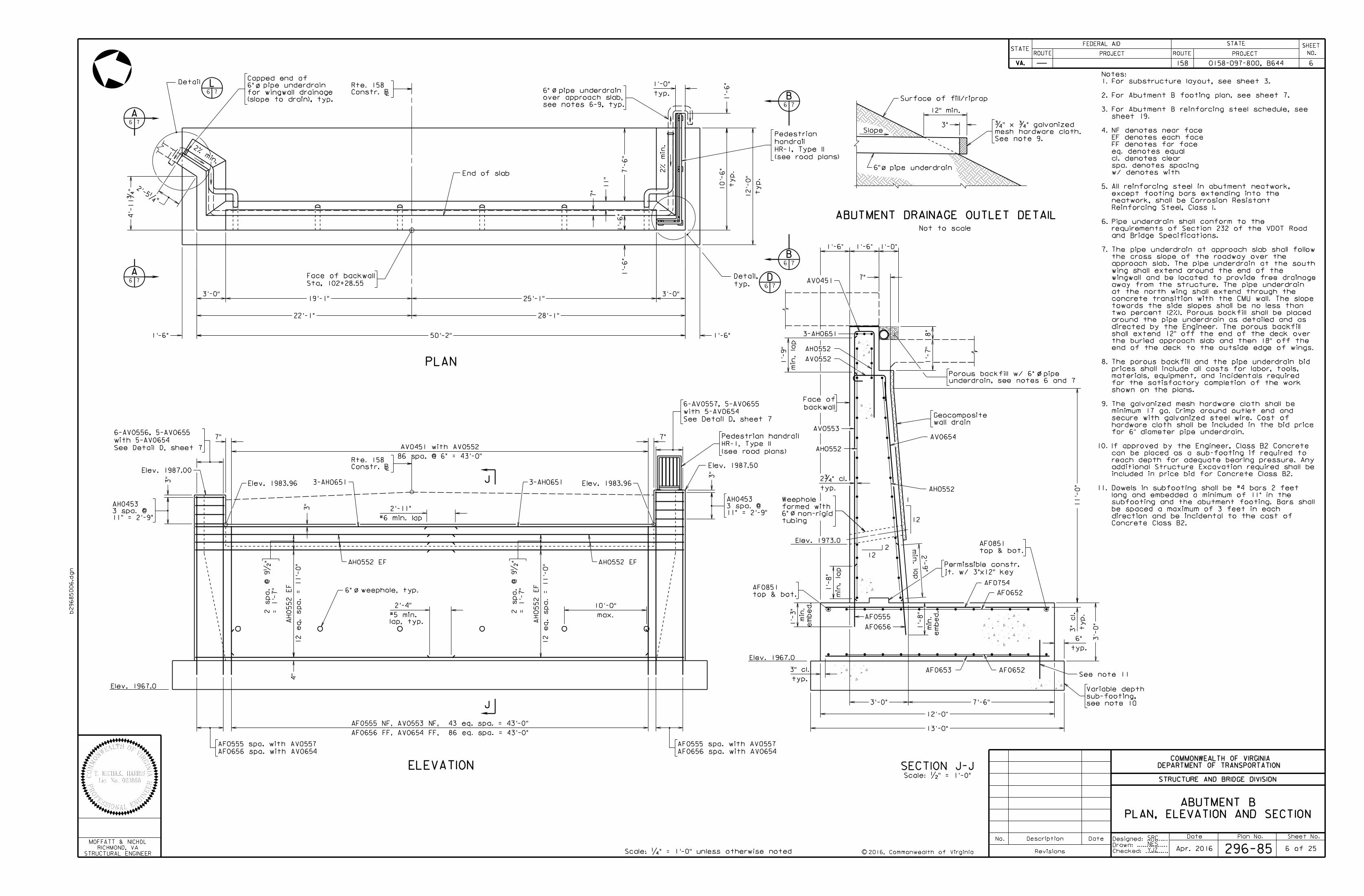
PLAN, ELEVATION AND SECTION
ABUTMENT B
6
PLAN
ELEVATION
Elev. 1967.0
L
J
J
L
SRC
NES6 of 25
2016, Commonwealth of Virginia
A6 7
A6 7
B6 7
B6 7
Sta, 102+28.55
Face of backwall
4'-
11ƒ
"
25'-1"19'-1"3'-0"
28'-1"22'-1"
50'-2"1'-6"
typ.
1'-0"
1'-
6"
1'-
6"
1'-
6"
7'-
6"
7"
11"
ty
p.
10'-
6"
ty
p.
12'-
0"
1'-6"
D6 7
Elev. 1987.00Elev. 1987.50
Apr. 2016
2% min.
7"
Constr. B
Rte. 158
Constr. B
Rte. 158
SECTION J-JScale: •" = 1'-0"
wall drain
Geocomposite
8"
1'-
7"
o/o/
1'-0"
underdrain, see notes 6 and 7
Porous backfill w/ 6" pipe
1
12
1'-6"
7"
7'-6"3'-0"
jt. w/ 3"x12" key
Permissible constr.
AH0552
AV0654
AV0553
AH0552
AF0652
AF0754
min. la
p
1'-
8"
AF0652
12'-0"
AF0653
AV0451
AV0552
1'-6"
typ.
6"
3-AH0651
1'-
8"
AF0555
AF0656
min. la
p
2'-
9"
typ.
2ƒ" cl.
min. la
p
1'-
9"
7"
End of slab
YJZ
AH0552
13'-0"
Elev. 1967.0
86 spa. @ 6" = 43'-0"
AV0451 with AV0552
AF0656 spa. with AV0654
AF0555 spa. with AV0557
AF0656 spa. with AV0654
AF0555 spa. with AV0557
AF0656 FF, AV0654 FF, 86 eq. spa. = 43'-0"
AF0555 NF, AV0553 NF, 43 eq. spa. = 43'-0"
em
bed.
min.
em
bed.
min.
2
12
top & bot.
AF0851
1'-
3"
top & bot.
AF0851
2%
min.
3"
See Detail D, sheet 7
with 5-AV0654
6-AV0556, 5-AV0655
3"
See Detail D, sheet 7
with 5-AV0654
6-AV0557, 5-AV0655
Elev. 1983.96Elev. 1983.96 3-AH06513-AH0651
o/
max.
10'-0"
3"
AH0552 EFAH0552 EF
= 1'-
7"
2 spa.
@ 9•
"
= 1'-
7"
2 spa.
@ 9•
"
2'-5‚"
typ.
3" cl.
(see road plans)
HR-1, Type II
Pedestrian handrail
Elev. 1973.0
o/6" weephole, typ.
#5 min.
2'-4"
lap, typ.
Detail L6 7
#6 min. lap
2'-11"
11" = 2'-9"
3 spa. @
AH0453
11" = 2'-9"
3 spa. @
AH0453
(slope to drain), typ.
for wingwall drainage
6" pipe underdrain
Capped end of
typ.
Detail,
3"
12" min.
Slope
See note 9.
mesh hardware cloth.
ƒ" x ƒ" galvanized
6" pipe underdrain
o/
Not to scale
ABUTMENT DRAINAGE OUTLET DETAIL
Surface of fill/riprap
see note 10
sub-footing,
Variable depth
See note 11
ty
p.
3"
cl.
o/
tubing
6" non-rigid
formed with
Weephole
backwall
Face of
11.
10.
9.
8.
7.
6.
5.
4.
3.
2.
1.
Notes:
11'-
0"
3'-
0"
(see road plans)
HR-1, Type II
handrail
Pedestrian
3'-0"
o/
see notes 6-9, typ.
over approach slab,
6" pipe underdrain
Concrete Class B2.
direction and be incidental to the cast of
be spaced a maximum of 3 feet in each
subfooting and the abutment footing. Bars shall
long and embedded a minimum of 11" in the
Dowels in subfooting shall be #4 bars 2 feet
included in price bid for Concrete Class B2.
additional Structure Excavation required shall be
reach depth for adequate bearing pressure. Any
can be placed as a sub-footing if required to
If approved by the Engineer, Class B2 Concrete
for 6" diameter pipe underdrain.
hardware cloth shall be included in the bid price
secure with galvanized steel wire. Cost of
minimum 17 ga. Crimp around outlet end and
The galvanized mesh hardware cloth shall be
shown on the plans.
for the satisfactory completion of the work
materials, equipment, and incidentals required
prices shall include all costs for labor, tools,
The porous backfill and the pipe underdrain bid
end of the deck to the outside edge of wings.
the buried approach slab and then 18" off the
shall extend 12" off the end of the deck over
directed by the Engineer. The porous backfill
around the pipe underdrain as detailed and as
two percent (2%). Porous backfill shall be placed
towards the side slopes shall be no less than
concrete transition with the CMU wall. The slope
at the north wing shall extend through the
away from the structure. The pipe underdrain
wingwall and be located to provide free drainage
wing shall extend around the end of the
approach slab. The pipe underdrain at the south
the cross slope of the roadway over the
The pipe underdrain at approach slab shall follow
and Bridge Specifications.
requirements of Section 232 of the VDOT Road
Pipe underdrain shall conform to the
Reinforcing Steel, Class I.
neatwork, shall be Corrosion Resistant
except footing bars extending into the
All reinforcing steel in abutment neatwork,
w/ denotes with
spa. denotes spacing
cl. denotes clear
eq. denotes equal
FF denotes far face
EF denotes each face
NF denotes near face
sheet 19.
For Abutment B reinforcing steel schedule, see
For Abutment B footing plan, see sheet 7.
For substructure layout, see sheet 3.
12 e
q.
spa.
= 11'-
0"
AH0552
EF
12 e
q.
spa.
= 11'-
0"
AH0552
EF
4"
Date Plan No. Sheet No.Designed: ...........
Drawn: ................
Checked: ............c
No. Description Date
STRUCTURE AND BRIDGE DIVISION
COMMONWEALTH OF VIRGINIA
DEPARTMENT OF TRANSPORTATION
Revisions
ROUTE
FEDERAL AID
PROJECT ROUTE PROJECT
STATE SHEET
NO.
VA.
STATEROUTE
FEDERAL AID
PROJECT ROUTE PROJECT
STATE SHEET
NO.
VA.
STATE
STRUCTURAL ENGINEER
RICHMOND, VA
MOFFATT & NICHOL
0158-097-800, B644158
Scale: ‚" = 1'-0" unless otherwise noted 296-85
7
SRC
NES7 of 25
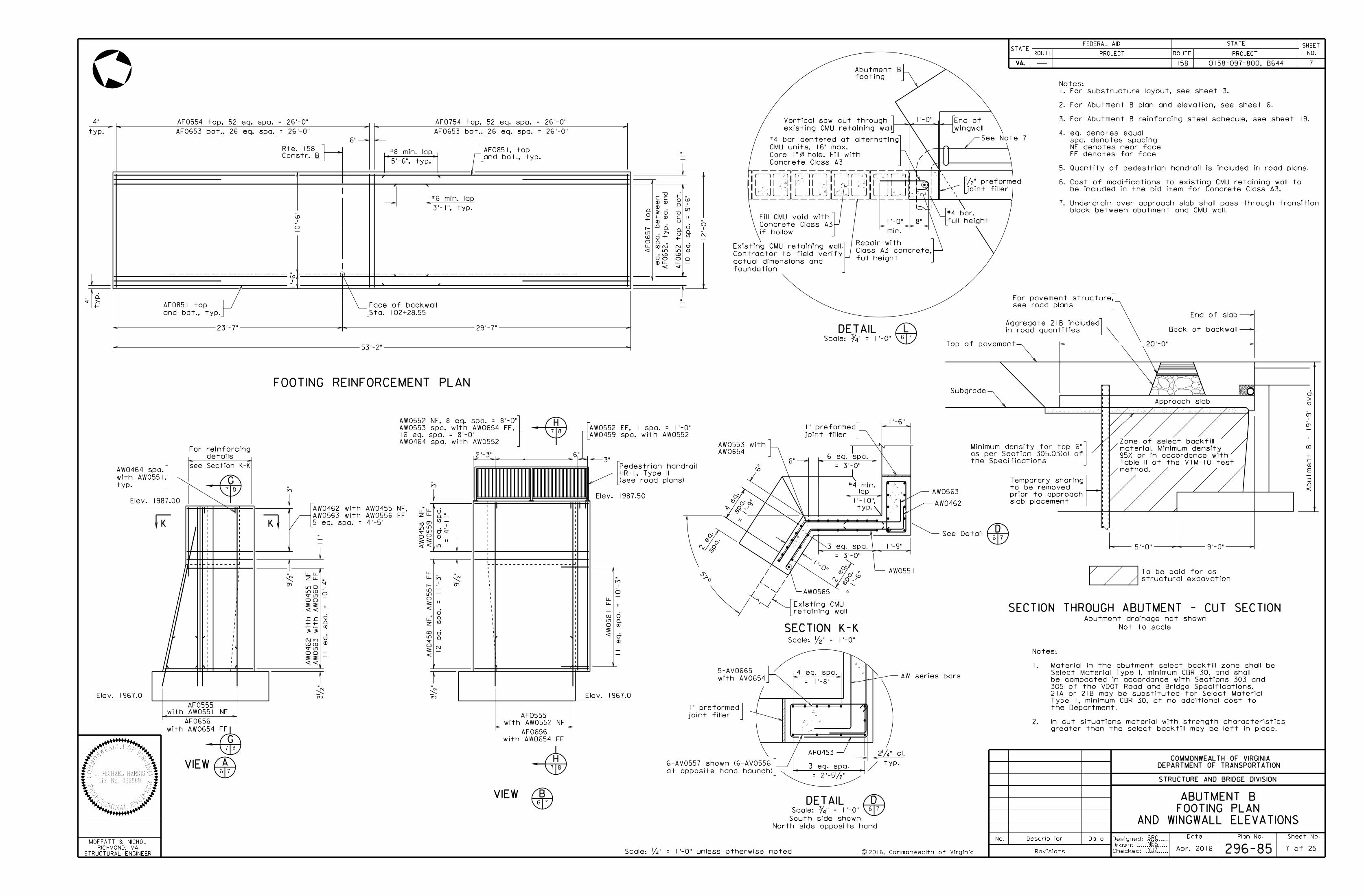
FOOTING REINFORCEMENT PLAN
2016, Commonwealth of Virginia
L
53'-2"
29'-7"23'-7"
10'-
6"
and bot., typ.
AF0851, top
typ.
4"
1'-
6"
Sta. 102+28.55
Face of backwall
and bot., typ.
AF0851 top
12'-
0"
11"
AF0652, ty
p.
ea.
end
11"
Apr. 2016
Constr. B
Rte. 158
the Specifications
as per Section 305.03(a) of
Minimum density for top 6"
Back of backwall
20'-0"
Subgrade
Approach slab
Top of pavement
structural excavation
To be paid for as
9'-0"5'-0"
method.
Table II of the VTM-10 test
95% or in accordance with
material. Minimum density
Zone of select backfill
End of slab
Not to scale
Abutment drainage not shown
SECTION THROUGH ABUTMENT - CUT SECTION
Abut
me
nt
B - 19'-
9"
avg.
AW series bars
AH0453
DETAIL D
typ.
2‚" cl.
Scale: ƒ" = 1'-0"
with AV0654
5-AV0665
= 1'-8"
4 eq. spa.
= 2'-5•"
3 eq. spa.
Elev. 1967.0Elev. 1967.0
VIEW6
VIEW6
Elev. 1987.00Elev. 1987.50
6"3"
For reinforcing
details
see Section K-K
KK
A
B
6"
AF0653 bot., 26 eq. spa. = 26'-0"
AF0554 top, 52 eq. spa. = 26'-0"
AF0653 bot., 26 eq. spa. = 26'-0"
AF0754 top, 52 eq. spa. = 26'-0"
AND WINGWALL ELEVATIONS
FOOTING PLAN
ABUTMENT B
Scale: •" = 1'-0"
o
1'-6"
SECTION K-K
AW0551
7 8
G
7 8
G
7
7
7 8
H
7 8
H
1'-9"
spa.
2 eq.
= 1'-
6"
spa.
4 eq.
= 1'-
9"
= 3'-0"
3 eq. spa.
spa.
2 eq.
6"
6"
57
AW0563
AW0462
9•
"3" 3"
11 e
q.
spa.
= 10'-
4"
AW
0563
wit
h
AW
0560
FF
3•
"
AW
0462
wit
h
AW
0455
NF
5 e
q.
spa.
AW
0559
FF
AW
0458
NF,
= 4'-
11"
9•
"
3•
"12 e
q.
spa.
= 11'-
3"
AW
0458
NF,
AW
0557
FF
at opposite hand haunch)
6-AV0557 shown (6-AV0556
6 7
5'-6", typ.
#8 min. lap
3'-1", typ.
#6 min. lap
10 e
q.
spa.
= 9'-
6"
AF0652 to
p and bot.
ty
p.
4"
2'-3"
11 e
q.
spa.
= 10'-
3"
AW
0561
FF
typ.
with AW0551,
AW0464 spa.
5 eq. spa. = 4'-5"
AW0563 with AW0556 FF
AW0462 with AW0455 NF,
AF0656
with AW0552 NF
AF0555
with AW0654 FF
AW0464 spa. with AW0552
16 eq. spa. = 8'-0"
AW0553 spa. with AW0654 FF,
AW0552 NF, 8 eq. spa. = 8'-0"
AW0459 spa. with AW0552
AW0552 EF, 1 spa. = 1'-0"
eq.
spa.
bet
wee
n
AF0657 to
p
AW0654
AW0553 with
1'-0"
1'-10",
lap#4 min.
typ.
= 3'-0"
6 eq. spa.
(see road plans)
HR-1, Type II
Pedestrian handrail
YJZ
see road plans
For pavement structure,
greater than the select backfill may be left in place.
In cut situations material with strength characteristics2.
the Department.
Type 1, minimum CBR 30, at no additional cost to
21A or 21B may be substituted for Select Material
305 of the VDOT Road and Bridge Specifications.
be compacted in accordance with Sections 303 and
Select Material Type I, minimum CBR 30, and shall
Material in the abutment select backfill zone shall be1.
Notes:
11"
in road quantities
Aggregate 21B included
footing
Abutment B
1'-0"
8"1'-0"
min.
full height
Class A3 concrete,
Repair with
o/
joint filler
•" preformed
DETAILScale: ƒ" = 1'-0" 6 7
L
wingwall
End of
full height
#4 bar,
AW0565
AF0555
AF0656
with AW0551 NF
with AW0654 FF
existing CMU retaining wall
Vertical saw cut through
wallretaining
Existing CMU
block between abutment and CMU wall.
Underdrain over approach slab shall pass through transition
be included in the bid item for Concrete Class A3.
Cost of modifications to existing CMU retaining wall to
Quantity of pedestrian handrail is included in road plans.
FF denotes far face
NF denotes near face
spa. denotes spacing
eq. denotes equal
For Abutment B reinforcing steel schedule, see sheet 19.
For Abutment B plan and elevation, see sheet 6.
For substructure layout, see sheet 3.
7.
6.
5.
4.
3.
2.
1.
Notes:
Concrete Class A3
Core 1" hole. Fill with
CMU units, 16" max.
#4 bar centered at alternating
if hollow
Concrete Class A3
Fill CMU void with
See Note 7
joint filler
1" preformed
North side opposite hand
South side shown
joint filler
1" preformed
See Detail6 7
D
foundation
actual dimensions and
verifyContractor to field
Existing CMU retaining wall.
slab placement
prior to approach
to be removed
Temporary shoring
Date Plan No. Sheet No.Designed: ...........
Drawn: ................
Checked: ............c
No. Description Date
STRUCTURE AND BRIDGE DIVISION
COMMONWEALTH OF VIRGINIA
DEPARTMENT OF TRANSPORTATION
Revisions
ROUTE
FEDERAL AID
PROJECT ROUTE PROJECT
STATE SHEET
NO.
VA.
STATEROUTE
FEDERAL AID
PROJECT ROUTE PROJECT
STATE SHEET
NO.
VA.
STATE
b29685008.d
gn
STRUCTURAL ENGINEER
RICHMOND, VA
MOFFATT & NICHOL
0158-097-800, B644158
296-85
SRC
NES
8
8 of 25
AW0501
AW0604
1'-0"
11'-
0"
3'-
0"
AW0412
AW0503
AF0606
3'-0"
AF0505
Scale: …" = 1'-0"
min.
1'-
8"
lap
min. la
p2'-
9"
AW0502
AW0604
1'-0"
11'-
0"
3'-
0"
AW0412
AW0503
AF0606
3'-0"
AF0505
Scale: …" = 1'-0"
min.
1'-
8"
lap
min. la
p2'-
9"
AW0551
AW0654
1'-0"
11'-
0"
3'-
0"
AW0464
AW0553
AF0656
3'-0"
AF0555
Scale: …" = 1'-0"
min.
1'-
8"
lap
min. la
p2'-
9"
AW0552
AW0654
wall drain
Geocomposite
1'-0"
11'-
0"
3'-
0"
AW0464
AW0553
AF0656
3'-0"
AF0555
Scale: …" = 1'-0"
min.
1'-
8"
lap
min. la
p2'-
9"
1'-
8"
1'-
3"
1'-
3"
1'-
8"
1'-
3"
1'-
8"
1'-
3"
1'-
8"
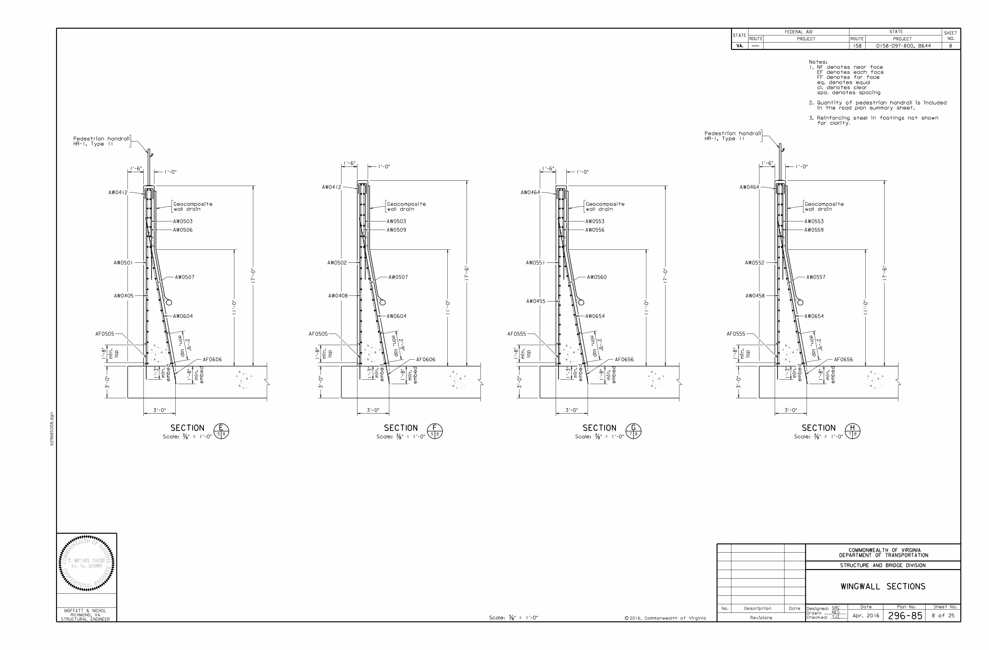
SECTION5 8
E SECTION5 8
F SECTION7 8
G SECTION7 8
H
wall drain
Geocomposite
wall drain
Geocomposite
wall drain
Geocomposite
AW0405
em
be
d
min.
em
be
d
min.
AW0507
HR-1, Type 11
Pedestrian handrail
AW0509
AW0408
AW0507
em
be
d
min.
em
be
d
min.
1'-6"
1'-6" 1'-6"
1'-6"
em
be
d
min.
em
be
d
min.
AW0560
AW0556
HR-1, Type 11
Pedestrian handrail
AW0458
em
be
d
min.
em
be
d
min.
AW0559
AW0557
WINGWALL SECTIONS
AW0506
17'-
6"
17'-
6"
AW0455
17'-
0"
17'-
0"
YJZ
3.
2.
1.
Notes:
for clarity.
Reinforcing steel in footings not shown
in the road plan summary sheet.
Quantity of pedestrian handrail is included
spa. denotes spacing
cl. denotes clear
eq. denotes equal
FF denotes far face
EF denotes each face
NF denotes near face
Scale: …" = 1'-0" 2016, Commonwealth of VirginiaApr. 2016
Date Plan No. Sheet No.Designed: ...........
Drawn: ................
Checked: ............c
No. Description Date
STRUCTURE AND BRIDGE DIVISION
COMMONWEALTH OF VIRGINIA
DEPARTMENT OF TRANSPORTATION
Revisions
ROUTE
FEDERAL AID
PROJECT ROUTE PROJECT
STATE SHEET
NO.
VA.
STATEROUTE
FEDERAL AID
PROJECT ROUTE PROJECT
STATE SHEET
NO.
VA.
STATE
b29685009.d
gn
Scale: •" = 1'-0"
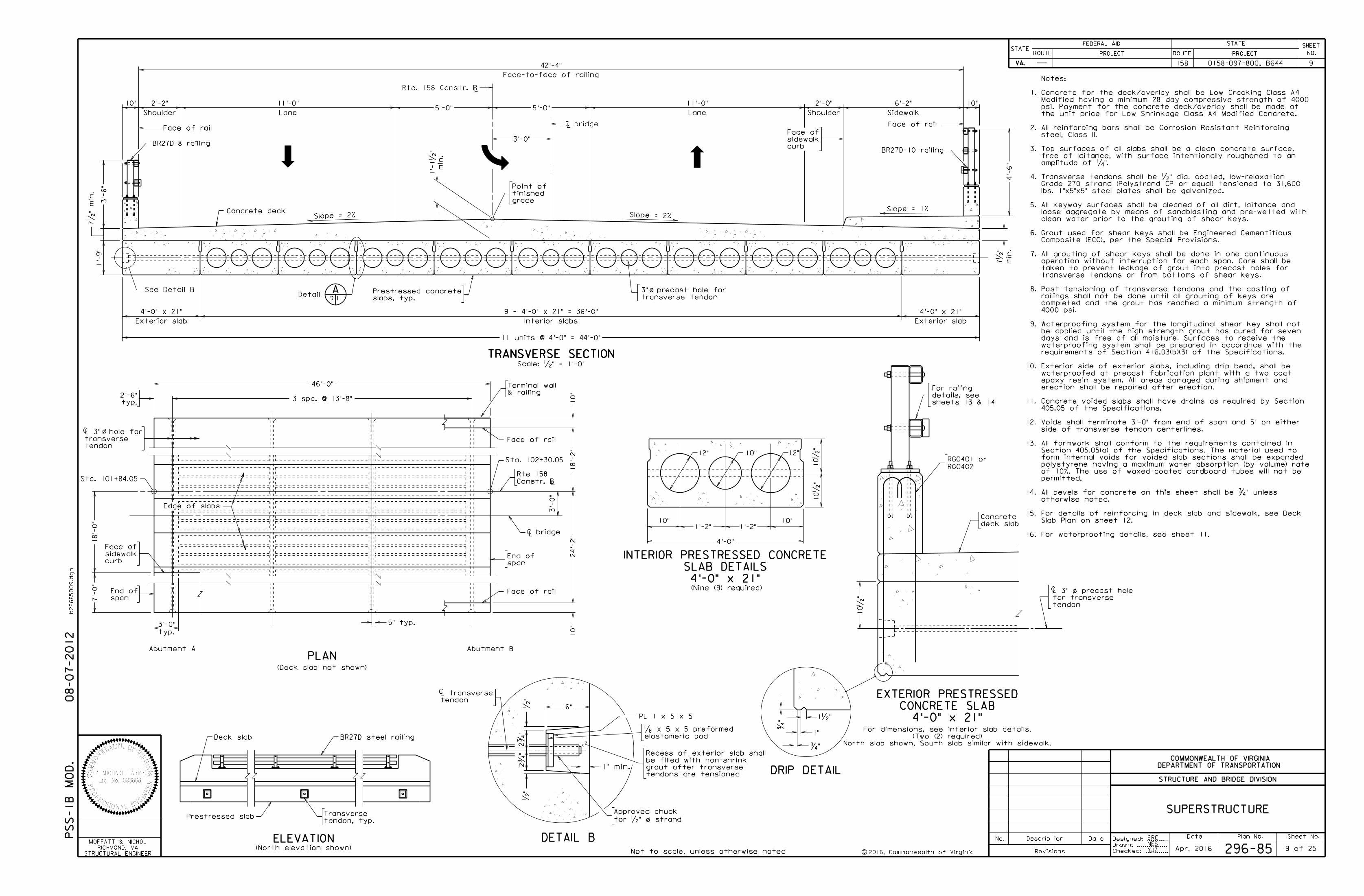
TRANSVERSE SECTIONTRANSVERSE SECTIONTRANSVERSE SECTION
0158-097-800, B644158
STRUCTURAL ENGINEER
RICHMOND, VA
MOFFATT & NICHOL
2016, Commonwealth of VirginiaApr. 2016
9
296-85
SRC
NES
10"
Sidewalk
6'-2"
Rte. 158 Constr. BL
Slope = 2%Slope = 2%
BR27D-10 railing
5'-0"5'-0"
BR27D-8 railing
4'-
6"
3'-
6"
Face-to-face of railing
42'-4"
11 units @ 4'-0" = 44'-0"
Concrete deck
Shoulder
2'-0"
Shoulder
2'-2"1'-
9"
1" min.
6"
elastomeric pad
DETAIL B
/
2ƒ
"2ƒ
"•
"•
"
„ x 5 x 5 preformed
PL 1 x 5 x 5
Approved chuck
for •" o strand
tendons are tensioned
grout after transverse
be filled with non-shrink
Recess of exterior slab shall
tendon
L transverse
ELEVATION
tendon, typ.
Transverse
BR27D steel railing
Prestressed slab
Edge of slabs
span
End of
typ.
2'-6"
C
PLAN
Not to scale, unless otherwise noted
(Nine (9) required)
C
12" 12"10"
10"1'-2" 1'-2"
4'-0"
10•
"10•
"
4'-0" x 21"
SLAB DETAILS
INTERIOR PRESTRESSED CONCRETE
10"
3 spa. @ 13'-8"
46'-0"
Rte 158
Constr. BL
Sta. 102+30.05
18'-
2"
tendon
transverse
L 3" hole for
Sta. 101+84.05
24'-
2"
typ.
3'-0" 5" typ.
Exterior slab
4'-0" x 21"
Interior slabs
9 - 4'-0" x 21" = 36'-0"
Exterior slab
4'-0" x 21"
grade
finished
Point of
Face of railFace of rail
7•
" min.
See Detail B o/
9 of 25
(Deck slab not shown)
Abutment A Abutment B
Deck slab
/C
4'-0" x 21"
CONCRETE SLAB
EXTERIOR PRESTRESSED
ƒ"
1•"
1"
ƒ"
DRIP DETAIL
10•
"
deck slab
Concrete
3'-
0"
& railing
Terminal wall
C bridgeL
7'-
0"
PS
S-1
B
MO
D.
08-07-2012
10"
Slope = 1%
curb
sidewalk
Face of
sheets 13 & 14
details, see
For railing
SUPERSTRUCTURE
10"
10"
curb
sidewalk
Face of
18'-
0"
span
End of
A9 11
Detail
RG0402
RG0401 or
tendon
for transverse
L 3" o precast hole
North slab shown, South slab similar with sidewalk.
(Two (2) required)
For dimensions, see interior slab details.
o/
Face of rail
Face of rail
Lane
11'-0"
Lane
11'-0"
slabs, typ.
Prestressed concretetransverse tendon
3" precast hole for
3'-0"
LC bridge
(North elevation shown)
16.
15.
14.
13.
12.
11.
10.
9.
8.
7.
6.
5.
4.
3.
2.
1.
YJZ
min.
1'-
1•
"
min.
7•
"
For waterproofing details, see sheet 11.
Slab Plan on sheet 12.
For details of reinforcing in deck slab and sidewalk, see Deck
otherwise noted.
All bevels for concrete on this sheet shall be ƒ" unless
permitted.
of 10%. The use of waxed-coated cardboard tubes will not be
polystyrene having a maximum water absorption (by volume) rate
form internal voids for voided slab sections shall be expanded
Section 405.05(a) of the Specifications. The material used to
All formwork shall conform to the requirements contained in
side of transverse tendon centerlines.
Voids shall terminate 3'-0" from end of span and 5" on either
405.05 of the Specifications.
Concrete voided slabs shall have drains as required by Section
erection shall be repaired after erection.
epoxy resin system. All areas damaged during shipment and
waterproofed at precast fabrication plant with a two coat
Exterior side of exterior slabs, including drip bead, shall be
requirements of Section 416.03(b)(3) of the Specifications.
waterproofing system shall be prepared in accordnce with the
days and is free of all moisture. Surfaces to receive the
be applied until the high strength grout has cured for seven
Waterproofing system for the longitudinal shear key shall not
4000 psi.
completed and the grout has reached a minimum strength of
railings shall not be done until all grouting of keys are
Post tensioning of transverse tendons and the casting of
transverse tendons or from bottoms of shear keys.
taken to prevent leakage of grout into precast holes for
operation without interruption for each span. Care shall be
All grouting of shear keys shall be done in one continuous
Composite (ECC), per the Special Provisions.
Grout used for shear keys shall be Engineered Cementitious
clean water prior to the grouting of shear keys.
loose aggregate by means of sandblasting and pre-wetted with
All keyway surfaces shall be cleaned of all dirt, laitance and
lbs. 1"x5"x5" steel plates shall be galvanized.
Grade 270 strand (Polystrand CP or equal) tensioned to 31,600
Transverse tendons shall be •" dia. coated, low-relaxation
amplitude of ‚".
free of laitance, with surface intentionally roughened to an
Top surfaces of all slabs shall be a clean concrete surface,
steel, Class II.
All reinforcing bars shall be Corrosion Resistant Reinforcing
the unit price for Low Shrinkage Class A4 Modified Concrete.
psi. Payment for the concrete deck/overlay shall be made at
Modified having a minimum 28 day compressive strength of 4000
Concrete for the deck/overlay shall be Low Cracking Class A4
Notes:
Mark No.
#5
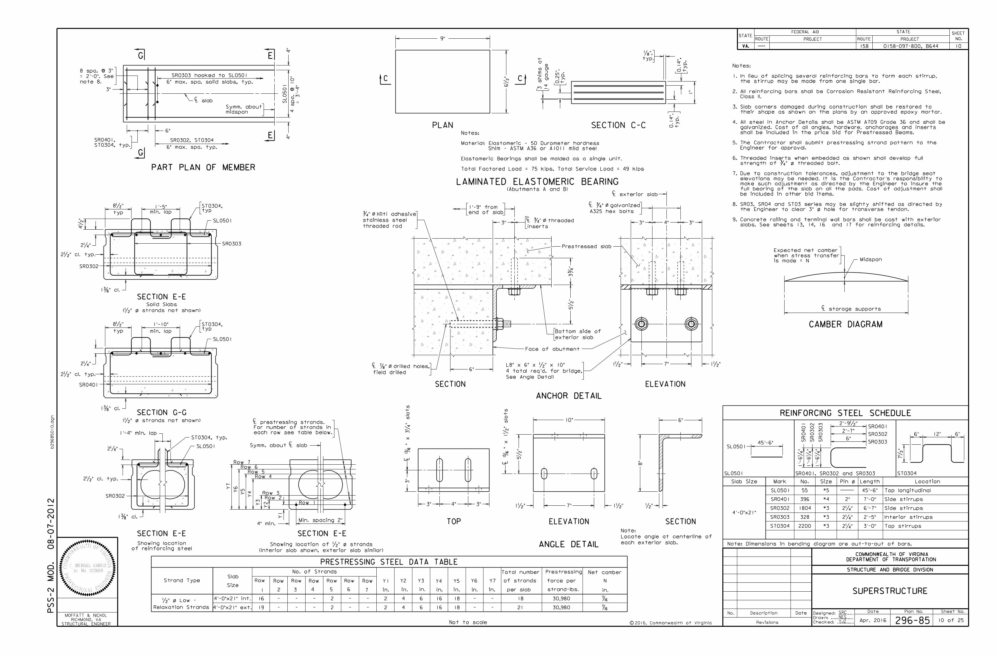
REINFORCING STEEL SCHEDULE
SizeSlab Size Length Location
#3
/
PART PLAN OF MEMBER
Midspan
CAMBER DIAGRAM
Strand Type
Relaxation Strands
Slab
Size
No. of Strands
Row
1 2 3 4 5 6 7
Row Row Row Row Row Row Y1 Y2 Y3 Y4 Y5 Y6 Y7
Total number
of strands
per slab
Prestressing
force per
strand-lbs.in. in. in. in. in. in. in.
/
SECTION E-E SECTION E-E
/
Net camber
N
in. SUPERSTRUCTURE
PRESTRESSING STEEL DATA TABLE
2•" cl. typ.
2‚"
1'-4" min. lap
SL0501 Symm. about L slab
Y7
Y6
Y5
Y4
Y3
Y2
Y1
Row 4
Row 3Row 2
Row 1
Min. spacing 2"
Pin o
Not to scale
1…" cl.
C
C
is made = N
when stress transfer
Expected net camber
L storage supportsC
SL0501
Date
STRUCTURE AND BRIDGE DIVISION
COMMONWEALTH OF VIRGINIA
DEPARTMENT OF TRANSPORTATION
of reinforcing steel
Showing location
08-07-2012
each row see table below.
For number of strands in
L prestressing strands.
Designed: ...........
Drawn: ................
Checked: ............2016, Commonwealth of Virginiac
No. Description Date
Revisions
ROUTE
FEDERAL AID
PROJECT ROUTE PROJECT
STATE SHEET
NO.
VA.
STATEROUTE
FEDERAL AID
PROJECT ROUTE PROJECT
STATE SHEET
NO.
VA.
STATE
b29685010.d
gn
296-85 10 of 25
Date Plan No. Sheet No.
0158-097-800, B644 10158
•" o Low -
SRC
NES
PS
S-2
MO
D.
/
16
19
-
-
-
-
-
-
2
2
-
-
-
-
2
2
4
4
6
6
16
16
18
18
-
-
-
-
18
21
‹
‹
4'-0"x21" int.
4'-0"x21" ext.
30,980
30,980
3"
E
E
SL0501
4 spa.
@ 10"
4"
4"
midspan
Symm. about
L slabC
= 3'-
4"
note 8.
= 2'-0". See
8 spa. @ 3"
/
SECTION G-G(•" o strands not shown)
min. lap
1'-10"
1…" cl.
2•" cl. typ.
SL0501
SR0401
typ
8•"
2‚"
typST0304,
PLAN
3 shim
s at
14 gauge
C C
9"
SECTION C-C
typ.
„",
LAMINATED ELASTOMERIC BEARING(Abutments A and B)
6•
"
ty
p.
0.2
5",
ty
p.
0.1
4",
1"
ty
p.
0.1
4",
STRUCTURAL ENGINEER
RICHMOND, VA
MOFFATT & NICHOL
SL0501
SR0302
SR0303
SR0401
SR0401
SR0302
SR0303
ST0304
12"6" 6"
Note: Dimensions in bending diagram are out-to-out of bars.
4'-0"x21"
Side stirrups
Top longitudinal
Side stirrups
Interior stirrups
SR0401
SR0302
SR0303
ST0304
SL0501
#3
#3
2‚"
2‚"
2"#4
Apr. 2016
SR0302
ST0304, typ.
G
G
ST0304, typ.
SR0401,
6"
SR0302, ST0304
6" max. spa. typ.
6" max. spa. solid slabs, typ.
SR0303 hooked to SL0501
SR0401, SR0302 and SR0303
2‚"
YJZ
Total Factored Load = 75 kips, Total Service Load = 49 kips
Elastomeric Bearings shall be molded as a single unit.
Shim - ASTM A36 or A1011 mild steel
Material: Elastomeric - 50 Durometer hardness
Notes:
/
SECTION E-E
min. lap
1'-5"
1…" cl.
2•" cl. typ.
SL0501
SR0302
typ
8•"
2‚"
typST0304,
SR0303
(•" o strands not shown)
Solid Slabs
o/
o/
o/
o/
6"
3"
3ƒ
"5•
"
Face of abutment
exterior slab
Bottom side of
Prestressed slab
1•"7"1•"
3" 4" 3"
See Angle Detail
4 total req'd. for bridge,
L8" x 6" x •" x 10"
threaded rod
stainless steel
ƒ" Hilti adhesive
L ‡" drilled holes,
field drilled
C
ELEVATIONSECTION
ANCHOR DETAIL
CL ƒ" galvanized
A325 hex bolts
CL ƒ" threaded
inserts
Row 5Row 6
Row 7 C1•"
8"
10" 6"
5•
"
7" •"1•"L
Ž"
x 1•
" slots
ELEVATION SECTION
C3"
TOP
ANGLE DETAIL each exterior slab.
Locate angle at centerline of
Note:
3" 4" 3"
L
Ž"
x 3‚
" slots
4•
"
/
9.
8.
7.
6.
5.
4.
3.
2.
1.
Notes:
45'-6"
55
396
1804
328
2200
45'-6"
7'-0"
6'-7"
2'-5"
3'-0" Top stirrups
1'-
6‚
"
1'-
6‚
"
1'-
6‚
"
2'-9•"
2'-7"
6"
7•
"
CL exterior slab
(Interior slab shown, exterior slab similar)
Showing location of •" o strands
end of slab
1'-9" from
4" min.
slabs. See sheets 13, 14, 16 and 17 for reinforcing details.
Concrete railing and terminal wall bars shall be cast with exterior
the Engineer to clear 3" o hole for transverse tendon.
SR03, SR04 and ST03 series may be slighty shifted as directed by
be included in other bid items.
full bearing of the slab on all the pads. Cost of adjustment shall
make such adjustment as directed by the Engineer to insure the
elevations may be needed. It is the Contractor's responsibility to
Due to construction tolerances, adjustment to the bridge seat
strength of ƒ" o threaded bolt.
Threaded inserts when embedded as shown shall develop full
Engineer for approval.
The Contractor shall submit prestressing strand pattern to the
shall be included in the price bid for Prestressed Beams.
galvanized. Cost of all angles, hardware, anchorages and inserts
All steel in Anchor Details shall be ASTM A709 Grade 36 and shall be
their shape as shown on the plans by an approved epoxy mortar.
Slab corners damaged during construction shall be restored to
Class II.
All reinforcing bars shall be Corrosion Resistant Reinforcing Steel,
the stirrup may be made from one single bar.
In lieu of splicing several reinforcing bars to form each stirrup,
2016, Commonwealth of VirginiacNot to scale
FOR CONCRETE OVERLAY
WATERPROOFING DETAILS
BEARING AND
Date Plan No. Sheet No.Designed: ...........
Drawn: ................
Checked: ............
No. Description Date
STRUCTURE AND BRIDGE DIVISION
COMMONWEALTH OF VIRGINIA
DEPARTMENT OF TRANSPORTATION
Revisions
ROUTE
FEDERAL AID
PROJECT ROUTE PROJECT
STATE SHEET
NO.
VA.
STATEROUTE
FEDERAL AID
PROJECT ROUTE PROJECT
STATE SHEET
NO.
VA.
STATE
b29685011.d
gn
End of slab
End of slab
PART PLAN AT ABUTMENT A PART PLAN AT ABUTMENT B
3" ty
p.
3" ty
p.
END BEARING DETAILS
WATERPROOFING MEMBRANE DETAIL
ABUTMENT B
6"
ABUTMENT A
4" typ.4" ty
p.
6"
Elastomeric bearing pad typ.
ty
p.
Bridge seat
6"
Edge of prestressed slab
6"
STRUCTURAL ENGINEER
RICHMOND, VA
MOFFATT & NICHOL
END OF SLAB VIEW AT ABUTMENTSEdge of prestressed slab
SRC
TPAApr. 2016 296-85 11 of 25
haunch
Top of wing
slab
prestessed
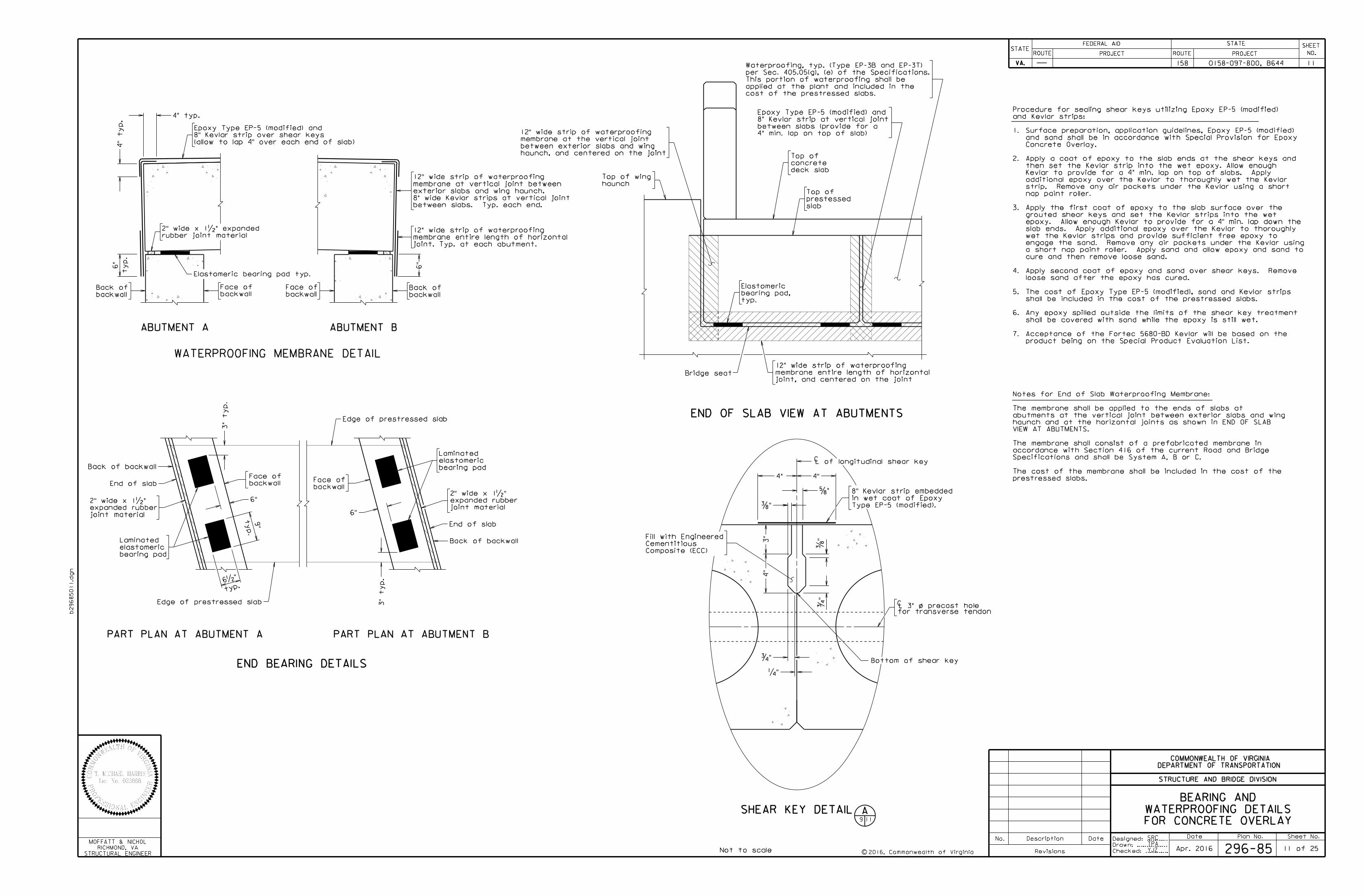
Top of
and Kevlar strips:
Procedure for sealing shear keys utilizing Epoxy EP-5 (modified)
Notes for End of Slab Waterproofing Membrane:
between slabs. Typ. each end.
8" wide Kevlar strips at vertical joint
exterior slabs and wing haunch.
membrane at vertical joint between
12" wide strip of waterproofing
deck slab
concrete
Top of
typ.
bearing pad,
Elastomeric
YJZ
7.
6.
5.
4.
3.
2.
1.
0158-097-800, B644158 11
rubber joint material
2" wide x 1•" expanded
backwall
Face of
backwall
Face of
backwall
Back of
backwall
Back of
joint. Typ. at each abutment.
membrane entire length of horizontal
12" wide strip of waterproofing
4" 4"
†"
L of longitudinal shear keyC
…"
Composite (ECC)
Cementitious
Fill with Engineered
…"
ƒ"
ƒ"
‚"
C/
for transverse tendonL 3" o precast hole
Back of backwall
typ.
9"
typ.
6•"
backwall
Face of
backwall
Face of
Back of backwall
4" min. lap on top of slab)
between slabs (provide for a
8" Kevlar strip at vertical joint
Epoxy Type EP-5 (modified) and
4"
3"
joint, and centered on the joint
membrane entire length of horizontal
12" wide strip of waterproofing
haunch, and centered on the joint
between exterior slabs and wing
membrane at the vertical joint
12" wide strip of waterproofing
Bottom of shear key
SHEAR KEY DETAIL9 11
A
product being on the Special Product Evaluation List.
Acceptance of the Fortec 5680-BD Kevlar will be based on the
shall be covered with sand while the epoxy is still wet.
Any epoxy spilled outside the limits of the shear key treatment
shall be included in the cost of the prestressed slabs.
The cost of Epoxy Type EP-5 (modified), sand and Kevlar strips
loose sand after the epoxy has cured.
Apply second coat of epoxy and sand over shear keys. Remove
cure and then remove loose sand.
a short nap paint roller. Apply sand and allow epoxy and sand to
engage the sand. Remove any air pockets under the Kevlar using
wet the Kevlar strips and provide sufficient free epoxy to
slab ends. Apply additional epoxy over the Kevlar to thoroughly
epoxy. Allow enough Kevlar to provide for a 4" min. lap down the
grouted shear keys and set the Kevlar strips into the wet
Apply the first coat of epoxy to the slab surface over the
nap paint roller.
strip. Remove any air pockets under the Kevlar using a short
additional epoxy over the Kevlar to thoroughly wet the Kevlar
Kevlar to provide for a 4" min. lap on top of slabs. Apply
then set the Kevlar strip into the wet epoxy. Allow enough
Apply a coat of epoxy to the slab ends at the shear keys and
Concrete Overlay.
and sand shall be in accordance with Special Provision for Epoxy
Surface preparation, application guidelines, Epoxy EP-5 (modified)
(allow to lap 4" over each end of slab)
8" Kevlar strip over shear keys
Epoxy Type EP-5 (modified) and
prestressed slabs.
The cost of the membrane shall be included in the cost of the
Specifications and shall be System A, B or C.
accordance with Section 416 of the current Road and Bridge
The membrane shall consist of a prefabricated membrane in
VIEW AT ABUTMENTS.
haunch and at the horizontal joints as shown in END OF SLAB
abutments at the vertical joint between exterior slabs and wing
The membrane shall be applied to the ends of slabs at
bearing pad
elastomeric
Laminated
joint material
expanded rubber
2" wide x 1•"
joint material
expanded rubber
2" wide x 1•"
bearing pad
elastomeric
Laminated
Type EP-5 (modified).
in wet coat of Epoxy
8" Kevlar strip embedded
cost of the prestressed slabs.
applied at the plant and included in the
This portion of waterproofing shall be
per Sec. 405.05(g), (e) of the Specifications.
Waterproofing, typ. (Type EP-3B and EP-3T)
Face of rail
1%
Type EP4 or
EP5 epoxy
6"
DETAIL C
See Detail C
6 eq. spa.
3" typ.
Point Elevation
1
2
3
ELEVATIONS
4
5
Date Plan No. Sheet No.Designed: ...........
Drawn: ................
Checked: ............c
No. Description Date
STRUCTURE AND BRIDGE DIVISION
COMMONWEALTH OF VIRGINIA
DEPARTMENT OF TRANSPORTATION
Revisions
ROUTE
FEDERAL AID
PROJECT ROUTE PROJECT
STATE SHEET
NO.
VA.
STATEROUTE
FEDERAL AID
PROJECT ROUTE PROJECT
STATE SHEET
NO.
VA.
STATE
b29685012.d
gn
STRUCTURAL ENGINEER
RICHMOND, VA
MOFFATT & NICHOL
296-85
0158-097-800, B644
158 12
12 of 25
YJZ
NES
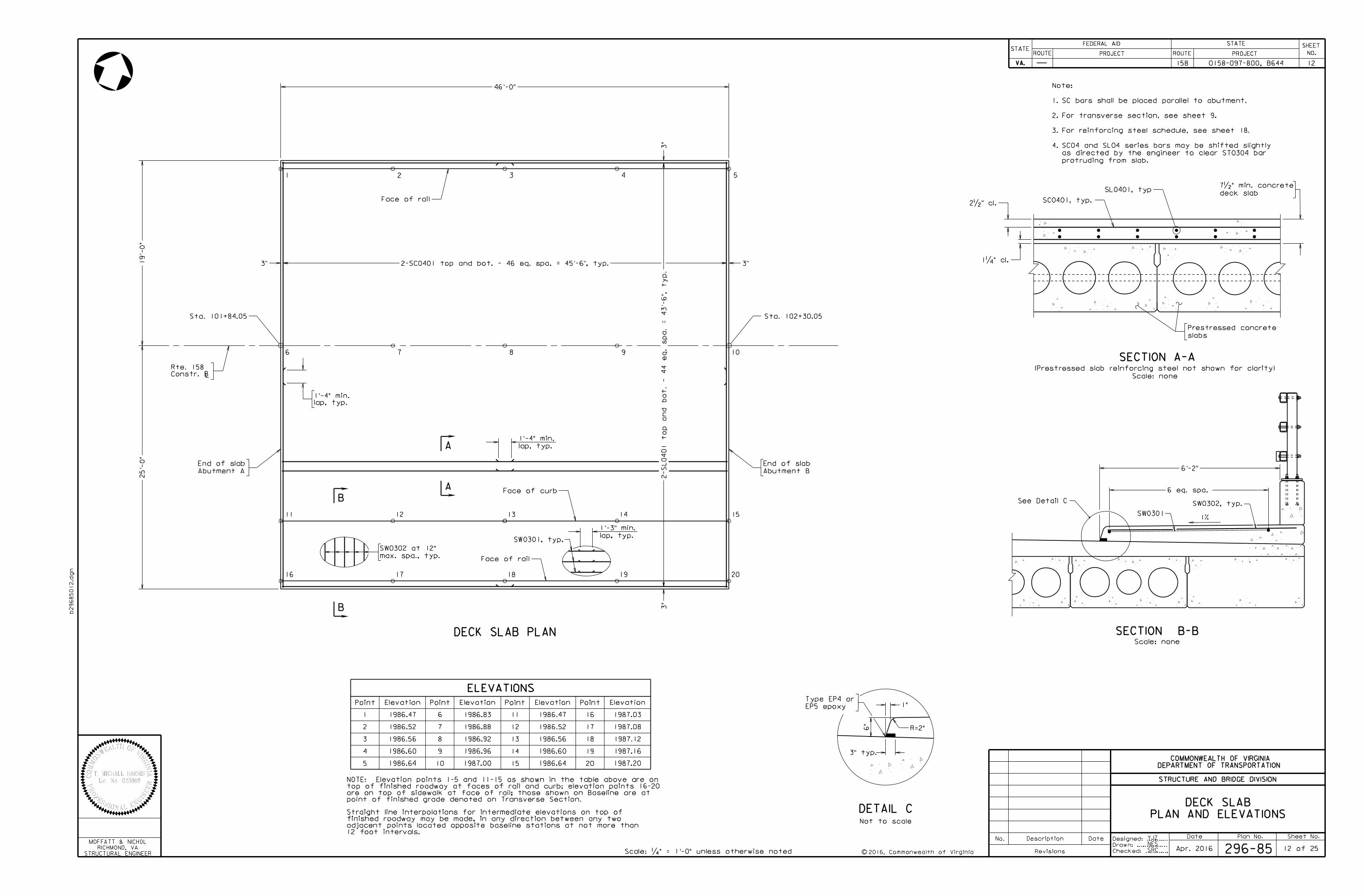
slabs
Prestressed concrete
SECTION A-A
Scale: none
(Prestressed slab reinforcing steel not shown for clarity)
2•" cl.
deck slab
7•" min. concreteSL0401, typ
51 2 3 4
6 7 8 9 10
16 17 18 19 20
Scale: ‚" = 1'-0" unless otherwise noted
L
Point
6
7
8
9
10
Elevation Point
11
12
13
14
15
Elevation
Face of rail
Abutment A
End of slab
Abutment B
End of slab
DECK SLAB PLAN
B
B
SECTION B-B
A
A
PLAN AND ELEVATIONS
DECK SLAB
11 12 13 14 15
Face of curb
Point
16
17
18
19
20
Elevation
1‚" cl.
SC0401, typ.
Sta. 102+30.05Sta. 101+84.05
Not to scale
lap, typ.
1'-4" min.
46'-0"
3"
3"
19'-
0"
25'-
0"
3" 3"
SW0301
SW0301, typ.
max. spa., typ.
SW0302 at 12"
1986.64
1986.60
1986.56
1986.52
1986.47
1987.00
1986.96
1986.92
1986.88
1986.83
1986.64
1986.60
1986.56
1986.52
1986.47
1987.20
1987.16
1987.12
1987.08
1987.03
2-S
L0401 to
p and bot. - 44 e
q.
spa.
= 43'-
6", ty
p.
lap, typ.
1'-3" min.
SW0302, typ.
Scale: none
Apr. 2016
Constr. B
Rte. 158
SRC
lap, typ.
1'-4" min.
4.
3.
2.
1.
Note:
12 foot intervals.
adjacent points located opposite baseline stations at not more than
finished roadway may be made, in any direction between any two
Straight line interpolations for intermediate elevations on top of
protruding from slab.
as directed by the engineer to clear ST0304 bar
SC04 and SL04 series bars may be shifted slightly
For reinforcing steel schedule, see sheet 18.
For transverse section, see sheet 9.
SC bars shall be placed parallel to abutment.
2-SC0401 top and bot. - 46 eq. spa. = 45'-6", typ.
6'-2"
1"
R=2"
point of finished grade denoted on Transverse Section.
are on top of sidewalk at face of rail; those shown on Baseline are at
top of finished roadway at faces of rail and curb; elevation points 16-20
NOTE: Elevation points 1-5 and 11-15 as shown in the table above are on
2016, Commonwealth of Virginia
Scale: ƒ" = 1'-0" unless otherwise noted.
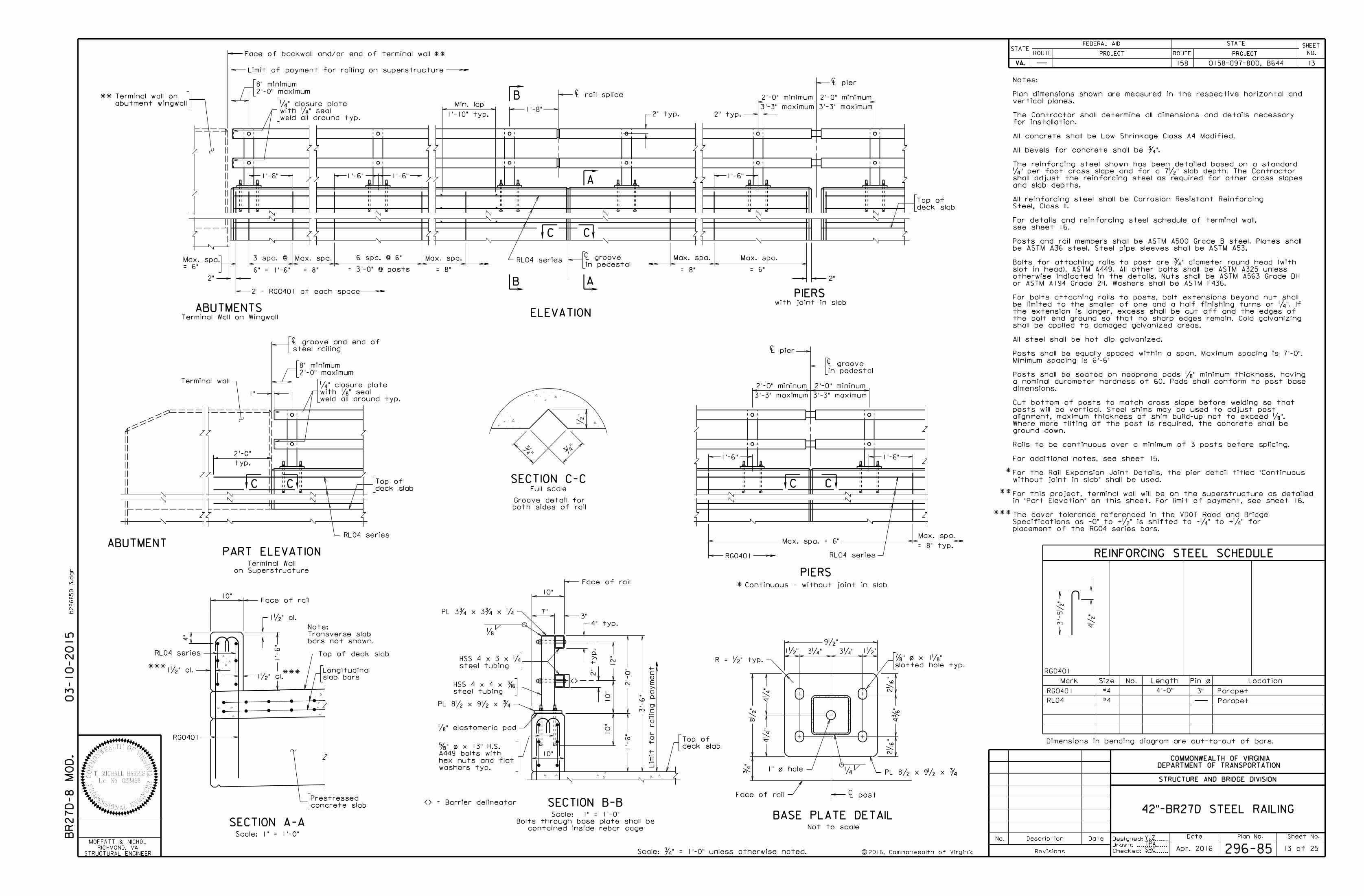
8" minimum
2'-0" maximum
Max. spa. Max. spa. Max. spa.
1'-6"
1'-8"
L pier
3 spa. @
6" = 1'-6"
6 spa. @ 6"
= 3'-0" @ posts
2" 2"
1'-6"
ABUTMENTS
PIERSwith joint in slab
ELEVATION
2" typ.
= 6"
Max. spa.
C
C
1'-6"
L rail splice
1'-6"
2" typ.
RL04 series
= 8" = 8" = 8"in pedestal
L grooveCMax. spa.
= 6"
2'-0" minimum
3'-3" maximum
2'-0" minimum
3'-3" maximum
weld all around typ.
with „" seal
‚" closure plate
3"
Face of rail
1'-
6"
3'-
6"
10"
7"
„2'-
0"
12"
„" elastomeric pad
4" typ.
2" ty
p.
Limit f
or railin
g pay
me
nt
PL 3ƒ x 3ƒ x ‚
PL 8• x 9• x ƒ
Top of deck slab
1'-
6"
RL04 series
1•" cl.
Face of rail
slab bars
Longitudinal
Max. spa.
Continuous - without joint in slab
PIERS
C
1'-6" 1'-6"
RL04 series
= 8" typ.Max. spa. = 6"
3'-3" maximum 3'-3" maximum
L pier
in pedestal
L grooveC8" minimum
2'-0" maximum
Terminal wall
1"
C
PART ELEVATION
on Superstructure
Terminal Wall
deck slab
Top of
RL04 series
deck slab
Top of
deck slab
Top of
weld all around typ.
with „" seal
‚" closure plate
steel tubing
HSS 4 x 3 x ‚
steel tubing
HSS 4 x 4 x ‰
B
A
C C
AB
C C C C
SECTION A-A
Limit of payment for railing on superstructure
steel railing
L groove and end of
Scale: 1" = 1'-0"
42"-BR27D STEEL RAILING
ABUTMENT
10"
10"
10"
10"
abutment wingwall
Terminal wall on
Terminal Wall on Wingwall
Full scale
Groove detail for
•"
ƒ"ƒ
"
both sides of rail
SECTION C-C
1•" cl.
SECTION B-B
BASE PLATE DETAIL
8•
"
4‚
"4‚
"
ƒ"
/R = •" typ.
PL 8• x 9• x ƒ
4…
"2ˆ
"2ˆ
"
1•" 1•"3‚" 3‚"
9•"
1" o hole/
Face of rail CL post
‚
slotted hole typ.
‡" o x 1„"
/
washers typ.
hex nuts and flat
A449 bolts with
†" o x 13" H.S.
Not to scalecontained inside rebar cage
Bolts through base plate shall be
Scale: 1" = 1'-0"
03-10-2015
REINFORCING STEEL SCHEDULE
Mark No.Size Length Location
RL04
Pin o/
#4
RG0401
Parapet
Dimensions in bending diagram are out-to-out of bars.
#4 Parapet3"RG0401
4•
"
1•" cl.
bars not shown.
Transverse slab
Note:
placement of the RG04 series bars.
Specifications as -0" to +•" is shifted to -‚" to +‚" for
The cover tolerance referenced in the VDOT Road and Bridge
Min. lap
1'-10" typ.
typ.
2'-0"
4"
Date Plan No. Sheet No.Designed: ...........
Drawn: ................
Checked: ............c
No. Description Date
STRUCTURE AND BRIDGE DIVISION
COMMONWEALTH OF VIRGINIA
DEPARTMENT OF TRANSPORTATION
Revisions
ROUTE
FEDERAL AID
PROJECT ROUTE PROJECT
STATE SHEET
NO.
VA.
STATEROUTE
FEDERAL AID
PROJECT ROUTE PROJECT
STATE SHEET
NO.
VA.
STATE
b29685013.d
gn
BR27
D-8
MO
D.
YJZ
TPA
296-85 13 of 25Apr. 2016
158 0158-097-800, B644 13
*
<>
<> = Barrier delineator
RG0401
2'-0" mininum 2'-0" mininum
STRUCTURAL ENGINEER
RICHMOND, VA
MOFFATT & NICHOL
RG0401
4'-0"
concrete slab
Prestressed
*
*
***
*
**
******
Face of backwall and/or end of terminal wall
SRC
**
2 - RG0401 at each space
3'-
5•
"
in "Part Elevation" on this sheet. For limit of payment, see sheet 16.
For this project, terminal wall will be on the superstructure as detailed
without joint in slab" shall be used.
For the Rail Expansion Joint Details, the pier detail titled "Continuous
For additional notes, see sheet 15.
Rails to be continuous over a minimum of 3 posts before splicing.
ground down.
Where more tilting of the post is required, the concrete shall be
alignment, maximum thickness of shim build-up not to exceed „".
posts will be vertical. Steel shims may be used to adjust post
Cut bottom of posts to match cross slope before welding so that
dimensions.
a nominal durometer hardness of 60. Pads shall conform to post base
Posts shall be seated on neoprene pads „" minimum thickness, having
Minimum spacing is 6'-6"
Posts shall be equally spaced within a span. Maximum spacing is 7'-0".
All steel shall be hot dip galvanized.
shall be applied to damaged galvanized areas.
the bolt end ground so that no sharp edges remain. Cold galvanizing
the extension is longer, excess shall be cut off and the edges of
be limited to the smaller of one and a half finishing turns or ‚". If
For bolts attaching rails to posts, bolt extensions beyond nut shall
or ASTM A194 Grade 2H. Washers shall be ASTM F436.
otherwise indicated in the details. Nuts shall be ASTM A563 Grade DH
slot in head), ASTM A449. All other bolts shall be ASTM A325 unless
Bolts for attaching rails to post are ƒ" diameter round head (with
be ASTM A36 steel. Steel pipe sleeves shall be ASTM A53.
Posts and rail members shall be ASTM A500 Grade B steel. Plates shall
see sheet 16.
For details and reinforcing steel schedule of terminal wall,
Steel, Class II.
All reinforcing steel shall be Corrosion Resistant Reinforcing
and slab depths.
shall adjust the reinforcing steel as required for other cross slopes
‚" per foot cross slope and for a 7•" slab depth. The Contractor
The reinforcing steel shown has been detailed based on a standard
All bevels for concrete shall be ƒ".
All concrete shall be Low Shrinkage Class A4 Modified.
for installation.
The Contractor shall determine all dimensions and details necessary
vertical planes.
Plan dimensions shown are measured in the respective horizontal and
Notes:
2016, Commonwealth of Virginia
Scale: ƒ" = 1'-0" unless otherwise noted.
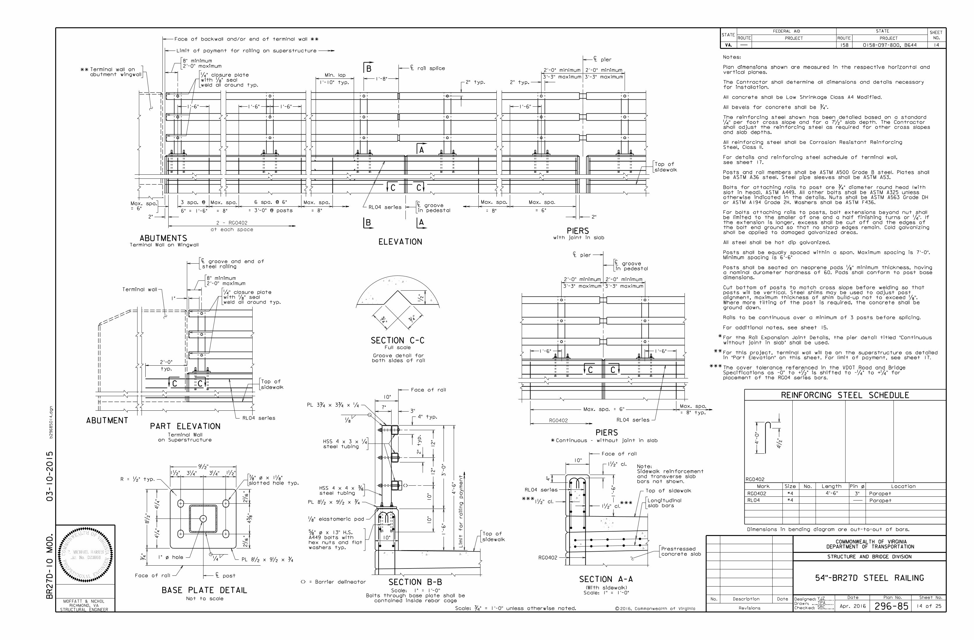
8" minimum
2'-0" maximum
Max. spa. Max. spa. Max. spa.
1'-8"
L pier
3 spa. @
6" = 1'-6"
6 spa. @ 6"
= 3'-0" @ posts
2" 2"
1'-6"
ABUTMENTSPIERS
with joint in slab
ELEVATION
2" typ.
= 6"
Max. spa.
C
C
1'-6"
L rail splice
1'-6"
2" typ.
RL04 series= 8" = 8" = 8"in pedestal
L grooveC Max. spa.
= 6"
2'-0" minimum
3'-3" maximum
2'-0" minimum
3'-3" maximum
weld all around typ.
with „" seal
‚" closure plate
8" minimum
2'-0" maximum
Terminal wall
1"
C
PART ELEVATION
on Superstructure
Terminal Wall
RL04 series
Max. spa.
Continuous - without joint in slab
PIERS
L pierC
1'-6" 1'-6"
RL04 series
= 8" typ.
2'-0" minimum
3'-3" maximum
2'-0" minimum
3'-3" maximum
Max. spa. = 6"
in pedestal
L grooveC
weld all around typ.
with „" seal
‚" closure plate
1'-6"
1'-
6"
4'-
6"
3'-
0"
12"
2" ty
p.
12"
4" typ.
3"
Face of rail
10"
7"
„
Limit f
or railin
g pay
me
nt
PL 3ƒ x 3ƒ x ‚
PL 8• x 9• x ƒ
Top of sidewalk
1'-
6"
1•" cl.
Face of rail
Scale: 1" = 1'-0"
(With sidewalk)
slab bars
Longitudinal
steel tubing
HSS 4 x 3 x ‚
steel tubing
HSS 4 x 4 x ‰
A
AB
B
C C
C C
C C
SECTION A-A
Limit of payment for railing on superstructure
steel railing
L groove and end of
54"-BR27D STEEL RAILING
ABUTMENT
Date Plan No. Sheet No.Designed: ...........
Drawn: ................
Checked: ............c
No. Description Date
STRUCTURE AND BRIDGE DIVISION
COMMONWEALTH OF VIRGINIA
DEPARTMENT OF TRANSPORTATION
Revisions
ROUTE
FEDERAL AID
PROJECT ROUTE PROJECT
STATE SHEET
NO.
VA.
STATEROUTE
FEDERAL AID
PROJECT ROUTE PROJECT
STATE SHEET
NO.
VA.
STATE
b29685014.d
gn
10"
10"
abutment wingwall
Terminal wall on
Terminal Wall on Wingwall
10"
Face of backwall and/or end of terminal wall
Full scale
Groove detail for
•"
ƒ"ƒ
"
both sides of rail
SECTION C-C
„" elastomeric pad
SECTION B-B
10"
RL04 series
1•" cl.
BASE PLATE DETAIL
8•
"
4‚
"4‚
"
ƒ"
/
R = •" typ.
PL 8• x 9• x ƒ
4…
"2ˆ
"2ˆ
"
1•" 1•"3‚" 3‚"
9•"
1" o hole/
Face of rail CL post
‚
slotted hole typ.
‡" o x 1„"
/
washers typ.
hex nuts and flat
A449 bolts with
†" o x 13" H.S.
contained inside rebar cage
Bolts through base plate shall be
Scale: 1" = 1'-0"
Not to scale
03-10-2015
REINFORCING STEEL SCHEDULE
Mark No.Size Length Location
RL04
Pin o/
#4 Parapet
Dimensions in bending diagram are out-to-out of bars.
#4 Parapet3"
1•" cl.
bars not shown.
and transverse slab
Sidewalk reinforcement
Note:
placement of the RG04 series bars.
Specifications as -0" to +•" is shifted to -‚" to +‚" for
The cover tolerance referenced in the VDOT Road and Bridge
Min. lap
1'-10" typ.
typ.
2'-0"
4"
YJZ
TPA
296-85 14 of 25Apr. 2016
BR27
D-10
MO
D.
STRUCTURAL ENGINEER
RICHMOND, VA
MOFFATT & NICHOL
4•
"
4'-
0"
RG0402
RG0402 4'-6"
RG0402
<> = Barrier delineator
<>
sidewalk
Top of
sidewalk
Top of
sidewalk
Top of
concrete slab
Prestressed
RG0402
158 0158-097-800, B644 14
SRC
*****
*
**
**
*
*
*
**
**
2 - RG0402
at each space
in "Part Elevation" on this sheet. For limit of payment, see sheet 17.
For this project, terminal wall will be on the superstructure as detailed
without joint in slab" shall be used.
For the Rail Expansion Joint Details, the pier detail titled "Continuous
For additional notes, see sheet 15.
Rails to be continuous over a minimum of 3 posts before splicing.
ground down.
Where more tilting of the post is required, the concrete shall be
alignment, maximum thickness of shim build-up not to exceed „".
posts will be vertical. Steel shims may be used to adjust post
Cut bottom of posts to match cross slope before welding so that
dimensions.
a nominal durometer hardness of 60. Pads shall conform to post base
Posts shall be seated on neoprene pads „" minimum thickness, having
Minimum spacing is 6'-6"
Posts shall be equally spaced within a span. Maximum spacing is 7'-0".
All steel shall be hot dip galvanized.
shall be applied to damaged galvanized areas.
the bolt end ground so that no sharp edges remain. Cold galvanizing
the extension is longer, excess shall be cut off and the edges of
be limited to the smaller of one and a half finishing turns or ‚". If
For bolts attaching rails to posts, bolt extensions beyond nut shall
or ASTM A194 Grade 2H. Washers shall be ASTM F436.
otherwise indicated in the details. Nuts shall be ASTM A563 Grade DH
slot in head), ASTM A449. All other bolts shall be ASTM A325 unless
Bolts for attaching rails to post are ƒ" diameter round head (with
be ASTM A36 steel. Steel pipe sleeves shall be ASTM A53.
Posts and rail members shall be ASTM A500 Grade B steel. Plates shall
see sheet 17.
For details and reinforcing steel schedule of terminal wall,
Steel, Class II.
All reinforcing steel shall be Corrosion Resistant Reinforcing
and slab depths.
shall adjust the reinforcing steel as required for other cross slopes
‚" per foot cross slope and for a 7•" slab depth. The Contractor
The reinforcing steel shown has been detailed based on a standard
All bevels for concrete shall be ƒ".
All concrete shall be Low Shrinkage Class A4 Modified.
for installation.
The Contractor shall determine all dimensions and details necessary
vertical planes.
Plan dimensions shown are measured in the respective horizontal and
Notes:
2016, Commonwealth of Virginia
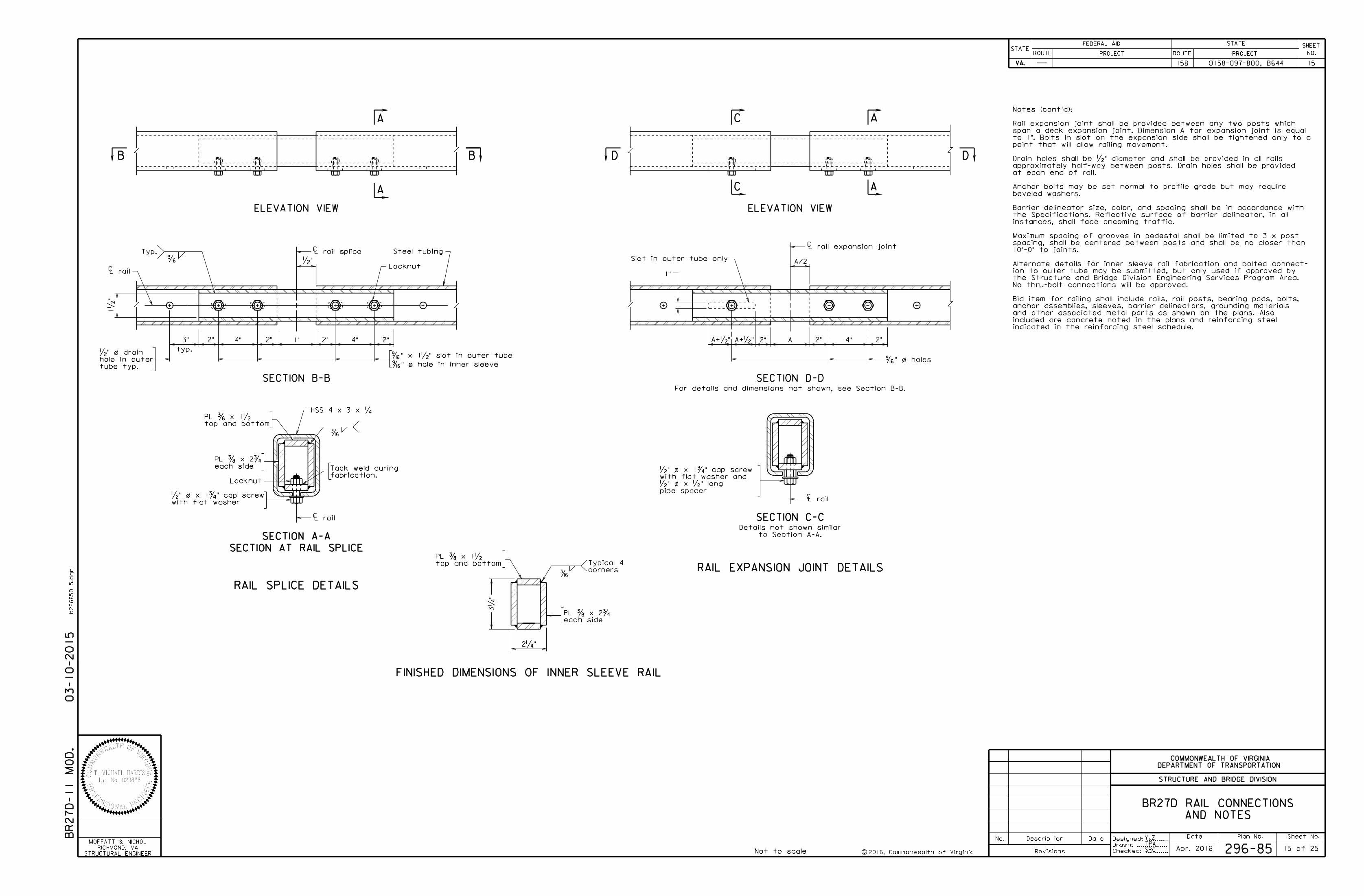
‰
Locknut
SECTION A-A
SECTION C-C
‰
3‚
"
SECTION AT RAIL SPLICE
Steel tubing
Locknut
3"
typ.
2"
1•
"
2"2" 2"
‰
Typ.
SECTION B-B
Not to scale
RAIL SPLICE DETAILS
ELEVATION VIEW
BB
A
•"
4" 4"1"
L rail spliceC
Œ" x 1•" slot in outer tube
Œ" o hole in inner sleeve
2"2"
SECTION D-D
ELEVATION VIEW
DD
A
A
4"A
A/2
RAIL EXPANSION JOINT DETAILS
L rail expansion joint
For details and dimensions not shown, see Section B-B.
2"A+•" A+•"
1"
Slot in outer tube only
CL rail
CL rail
2‚"
/
/
C
Œ" o holes/
A
/
/
FINISHED DIMENSIONS OF INNER SLEEVE RAIL
/
corners
Typical 4
top and bottom
PL … x 1•
each side
PL … x 2ƒ
top and bottom
PL … x 1•
each side
PL … x 2ƒ
HSS 4 x 3 x ‚
L railC
tube typ.
hole in outer
•" o drain
fabrication.
Tack weld during
to Section A-A.
Details not shown similar
AND NOTES
BR27D RAIL CONNECTIONS
with flat washer
•" o x 1ƒ" cap screwpipe spacer
•" o x •" long
with flat washer and
•" o x 1ƒ" cap screw
C
C
03-10-2015
Date Plan No. Sheet No.Designed: ...........
Drawn: ................
Checked: ............c
No. Description Date
STRUCTURE AND BRIDGE DIVISION
COMMONWEALTH OF VIRGINIA
DEPARTMENT OF TRANSPORTATION
Revisions
ROUTE
FEDERAL AID
PROJECT ROUTE PROJECT
STATE SHEET
NO.
VA.
STATEROUTE
FEDERAL AID
PROJECT ROUTE PROJECT
STATE SHEET
NO.
VA.
STATE
b29685015.d
gn
BR27
D-11
MO
D.
Apr. 2016 296-85 15 of 25
158 0158-097-800, B644 15
STRUCTURAL ENGINEER
RICHMOND, VA
MOFFATT & NICHOLYJZ
TPA
SRC
indicated in the reinforcing steel schedule.
included are concrete noted in the plans and reinforcing steel
and other associated metal parts as shown on the plans. Also
anchor assemblies, sleeves, barrier delineators, grounding materials
Bid item for railing shall include rails, rail posts, bearing pads, bolts,
No thru-bolt connections will be approved.
the Structure and Bridge Division Engineering Services Program Area.
ion to outer tube may be submitted, but only used if approved by
Alternate details for inner sleeve rail fabrication and bolted connect-
10'-0" to joints.
spacing, shall be centered between posts and shall be no closer than
Maximum spacing of grooves in pedestal shall be limited to 3 x post
instances, shall face oncoming traffic.
the Specifications. Reflective surface of barrier delineator, in all
Barrier delineator size, color, and spacing shall be in accordance with
beveled washers.
Anchor bolts may be set normal to profile grade but may require
at each end of rail.
approximately half-way between posts. Drain holes shall be provided
Drain holes shall be •" diameter and shall be provided in all rails
point that will allow railing movement.
to 1". Bolts in slot on the expansion side shall be tightened only to a
span a deck expansion joint. Dimension A for expansion joint is equal
Rail expansion joint shall be provided between any two posts which
Notes (cont'd):
2016, Commonwealth of Virginia
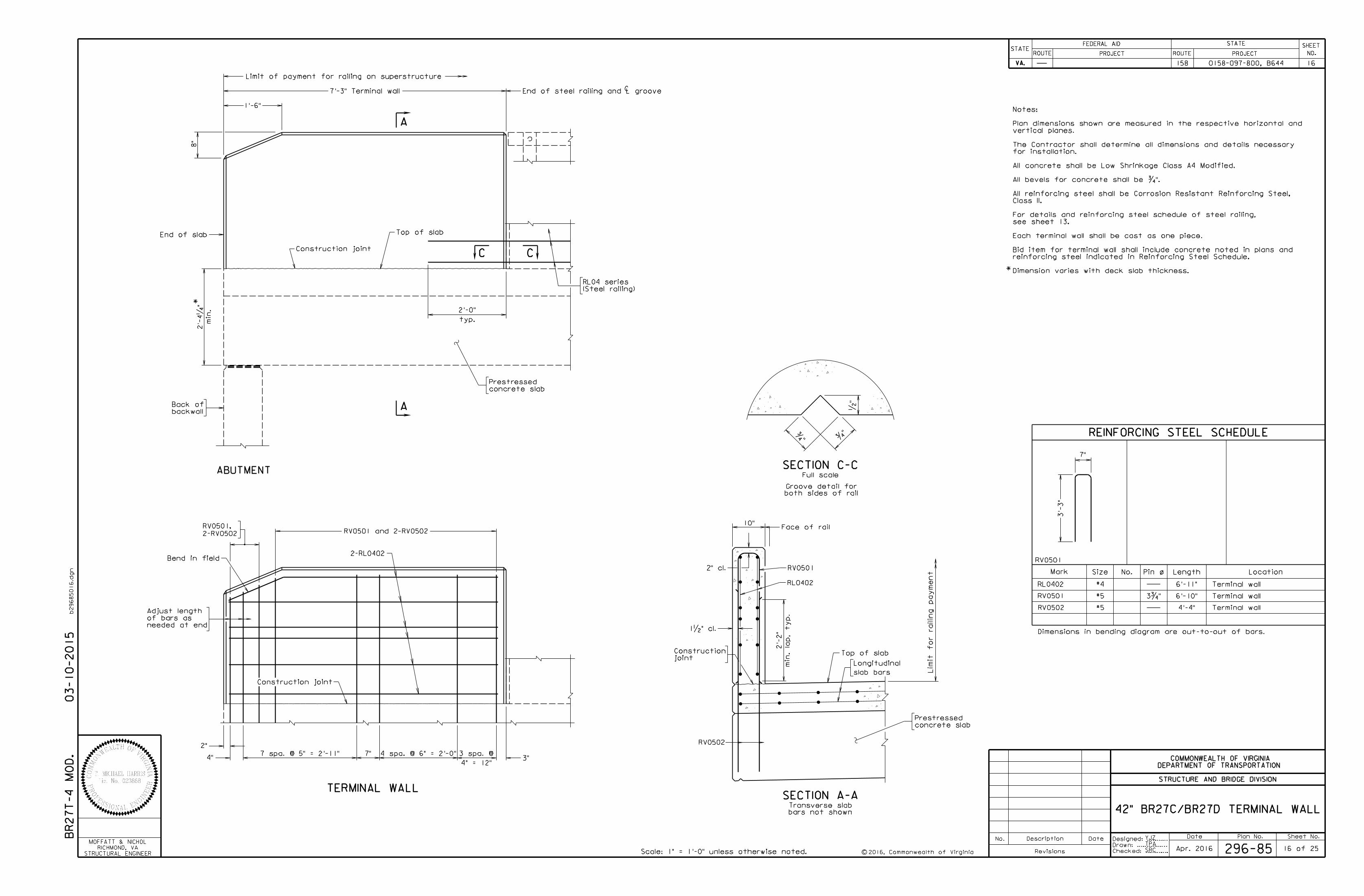
Date Plan No. Sheet No.Designed: ...........
Drawn: ................
c
No. Description Date
STRUCTURE AND BRIDGE DIVISION
COMMONWEALTH OF VIRGINIA
DEPARTMENT OF TRANSPORTATION
Revisions
ROUTE
FEDERAL AID
PROJECT ROUTE PROJECT
STATE SHEET
NO.
VA.
STATEROUTE
FEDERAL AID
PROJECT ROUTE PROJECT
STATE SHEET
NO.
VA.
STATE
b29685016.d
gn
/
REINFORCING STEEL SCHEDULE
Mark Size No. LengthPin o Location
#4 Terminal wall
Terminal wall
RV0501
RL0402 6'-11"
RV0501
RV0502 Terminal wall
#5 3ƒ"
#5
End of slab
Construction joint
typ.
(Steel railing)
RL04 series
Top of slab
Scale: 1" = 1'-0" unless otherwise noted.
Full scale
Groove detail for
•"
ƒ"ƒ
"
both sides of rail
SECTION C-C
C C
7" 4 spa. @ 6" = 2'-0"3 spa. @
4" = 12"3"4"
2"
Construction joint
TERMINAL WALL
RV0501
Limit f
or railin
g pay
me
nt
RL0402
42" BR27C/BR27D TERMINAL WALL
10"Face of rail
Bend in field
needed at end
of bars as
Adjust length
joint
Construction
backwall
Back of
1'-6"
8"
Limit of payment for railing on superstructure
7'-3" Terminal wall End of steel railing and L grooveC
bars not shown
Transverse slab
7 spa. @ 5" = 2'-11"
03-10-2015 Dimensions in bending diagram are out-to-out of bars.
7"
2'-0"
4'-4"
BR27
T-4
MO
D.
YJZ
TPA
296-85 16 of 25Apr. 2016STRUCTURAL ENGINEER
RICHMOND, VA
MOFFATT & NICHOL
concrete slab
Prestressed
concrete slab
Prestressed
2'-
4‚
"
min.
158 0158-097-800, B644 16
Checked: ............SRC
RV0501 and 2-RV05022-RV0502
RV0501,
2-RL0402
RV0502
Top of slab
slab bars
Longitudinal
SECTION A-A
A
A
3'-
3"
6'-10"
2'-
2"
min. la
p, ty
p.
2" cl.
1•" cl.
ABUTMENT
Dimension varies with deck slab thickness.
reinforcing steel indicated in Reinforcing Steel Schedule.
Bid item for terminal wall shall include concrete noted in plans and
Each terminal wall shall be cast as one piece.
see sheet 13.
For details and reinforcing steel schedule of steel railing,
Class II.
All reinforcing steel shall be Corrosion Resistant Reinforcing Steel,
All bevels for concrete shall be ƒ".
All concrete shall be Low Shrinkage Class A4 Modified.
for installation.
The Contractor shall determine all dimensions and details necessary
vertical planes.
Plan dimensions shown are measured in the respective horizontal and
Notes:
2016, Commonwealth of Virginia
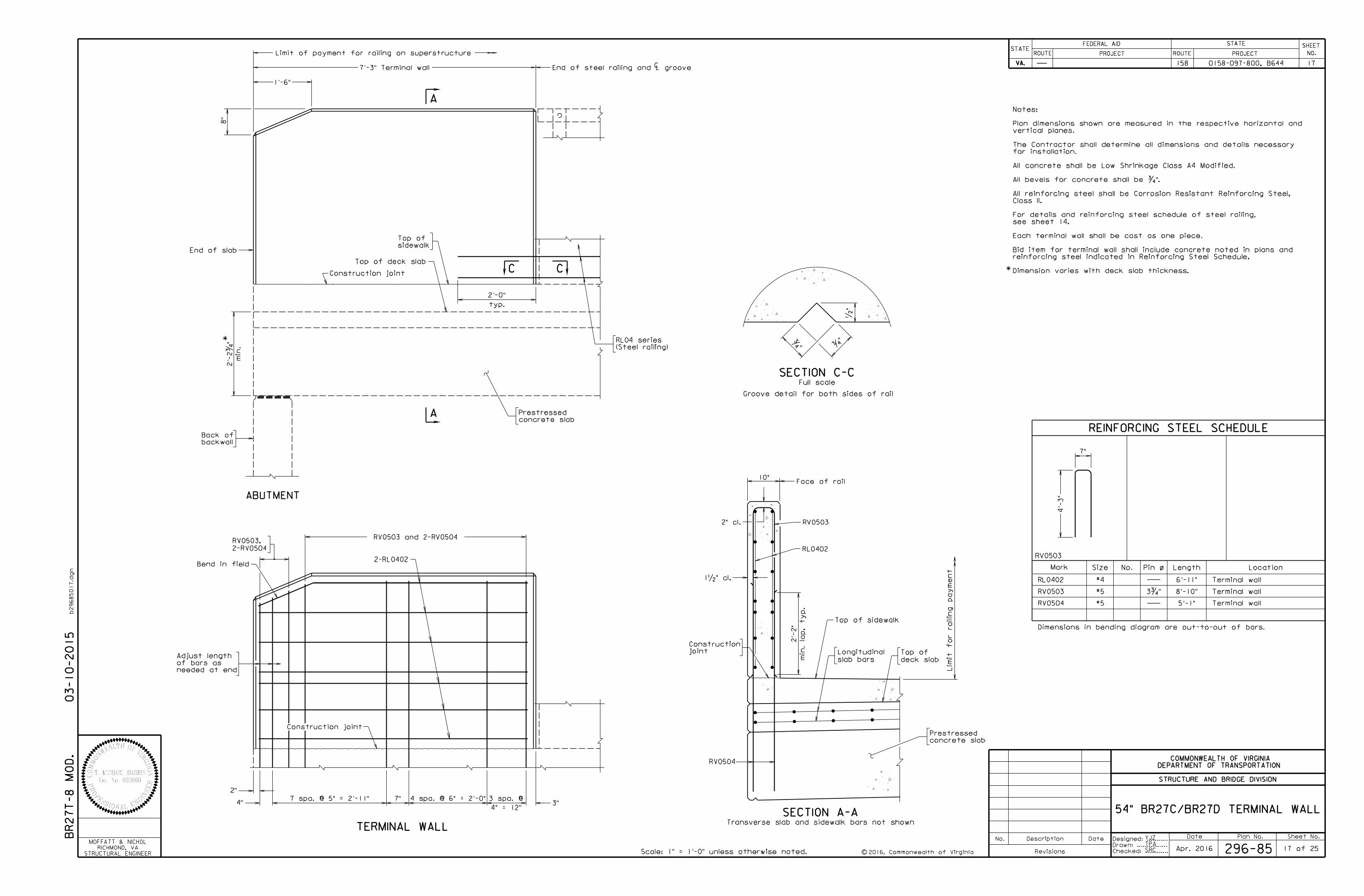
Date Plan No. Sheet No.Designed: ...........
Drawn: ................
Checked: ............c
No. Description Date
STRUCTURE AND BRIDGE DIVISION
COMMONWEALTH OF VIRGINIA
DEPARTMENT OF TRANSPORTATION
Revisions
ROUTE
FEDERAL AID
PROJECT ROUTE PROJECT
STATE SHEET
NO.
VA.
STATEROUTE
FEDERAL AID
PROJECT ROUTE PROJECT
STATE SHEET
NO.
VA.
STATE
b29685017.d
gn
Construction joint
typ.
(Steel railing)
RL04 series
Scale: 1" = 1'-0" unless otherwise noted.
TERMINAL WALL
Full scale
•"
ƒ"ƒ
"
SECTION C-C
C C
/
REINFORCING STEEL SCHEDULE
Mark Size No. LengthPin o Location
#4 Terminal wall
Terminal wall
RL0402 6'-11"
Terminal wall
#5 3ƒ"
#5
7" 4 spa. @ 6" = 2'-0"3 spa. @
4" = 12"3"4"
2"
54" BR27C/BR27D TERMINAL WALL
needed at end
of bars as
Adjust length
1'-6"
End of steel railing and L groove
Limit of payment for railing on superstructure
7'-3" Terminal wall C
8"
End of slab
backwall
Back of
Bend in field
7 spa. @ 5" = 2'-11"
03-10-2015
Dimensions in bending diagram are out-to-out of bars.
7"
2'-0"
5'-1"
YJZ
TPA
296-85 17 of 25Apr. 2016
Limit f
or railin
g pay
me
nt
RL0402
10"Face of rail
joint
Construction
concrete slab
PrestressedConstruction joint
158 0158-097-800, B644 17
BR27
T-8
MO
D.
STRUCTURAL ENGINEER
RICHMOND, VA
MOFFATT & NICHOL
2'-
2ƒ
"
min.
concrete slab
Prestressed
sidewalk
Top of
SRC
RV0503
RV0503
RV0504
RV0503
RV0503 and 2-RV0504
2-RL0402
2-RV0504
RV0503,
Top of sidewalk
slab bars
Longitudinal
RV0504
ABUTMENT
A
A
Top of deck slab
SECTION A-A
deck slab
Top of
Groove detail for both sides of rail
4'-
3"
8'-10"
2'-
2"
min. la
p, ty
p.
2" cl.
1•" cl.
Transverse slab and sidewalk bars not shown
Dimension varies with deck slab thickness.
reinforcing steel indicated in Reinforcing Steel Schedule.
Bid item for terminal wall shall include concrete noted in plans and
Each terminal wall shall be cast as one piece.
see sheet 14.
For details and reinforcing steel schedule of steel railing,
Class II.
All reinforcing steel shall be Corrosion Resistant Reinforcing Steel,
All bevels for concrete shall be ƒ".
All concrete shall be Low Shrinkage Class A4 Modified.
for installation.
The Contractor shall determine all dimensions and details necessary
vertical planes.
Plan dimensions shown are measured in the respective horizontal and
Notes:
2016, Commonwealth of Virginia
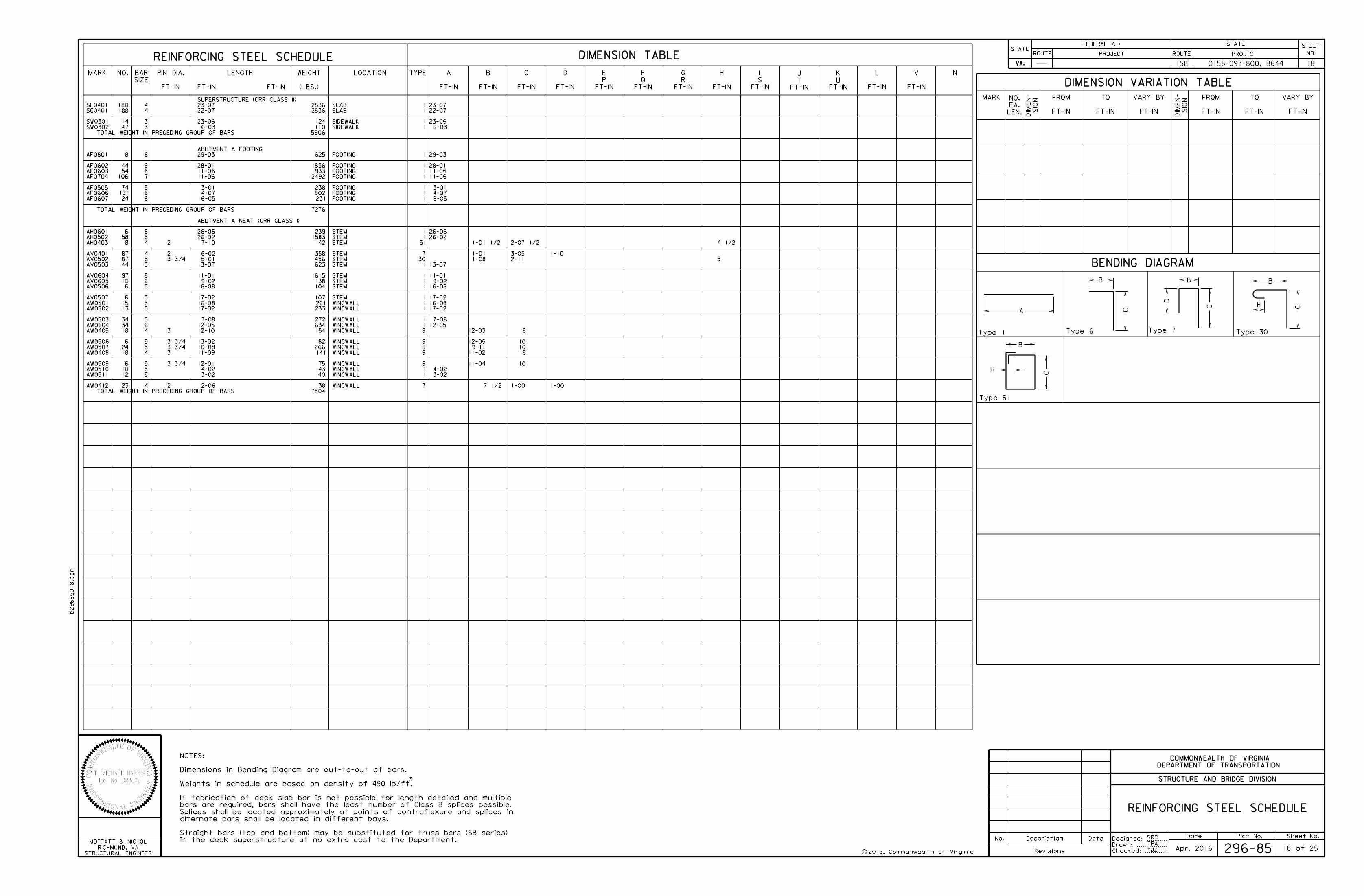
Date Plan No. Sheet No.Designed: ...........
Drawn: ................
Checked: ............2016, Commonwealth of Virginiac
No. Description Date
STRUCTURE AND BRIDGE DIVISION
COMMONWEALTH OF VIRGINIA
DEPARTMENT OF TRANSPORTATION
Revisions
ROUTE
FEDERAL AID
PROJECT ROUTE PROJECT
STATE SHEET
NO.
VA.
STATEROUTE
FEDERAL AID
PROJECT ROUTE PROJECT
STATE SHEET
NO.
VA.
STATE
REINFORCING STEEL SCHEDULE DIMENSION TABLE
MARK NO.
SIZE
BAR LOCATION TYPE N
(LBS.)
WEIGHT
BENDING DIAGRAM
DIMENSION VARIATION TABLE
MARK
LEN.
EA.
NO.
SIO
N
DIM
EN-
SIO
N
DIM
EN-
FT-IN
PIN DIA.
FT-IN FT-IN
LENGTH
FT-IN
A
FT-IN
B
FT-IN
C
FT-IN
D
FT-IN
P
E
FT-IN
Q
F
FT-IN
R
G
FT-IN
H
FT-IN
S
I
FT-IN
T
J
FT-IN
U
K
FT-IN
L
FT-IN
V
FT-IN
FROM
FT-IN
TO
FT-IN
VARY BY
FT-IN
FROM
FT-IN
TO
FT-IN
VARY BY
b29685018.d
gn
3
in the deck superstructure at no extra cost to the Department.
Straight bars (top and bottom) may be substituted for truss bars (SB series)
alternate bars shall be located in different bays.
Splices shall be located approximately at points of contraflexure and splices in
bars are required, bars shall have the least number of Class B splices possible.
If fabrication of deck slab bar is not possible for length detailed and multiple
Weights in schedule are based on density of 490 lb/ft.
Dimensions in Bending Diagram are out-to-out of bars.
NOTES:
STRUCTURAL ENGINEER
RICHMOND, VA
MOFFATT & NICHOLSRC
TPA
296-85 18 of 25
REINFORCING STEEL SCHEDULE
18158 0158-097-800, B644
Apr. 2016
23-07 23-07 2836SL0401 180 4 1SLAB
22-07 22-07 2836SC0401 188 4 1SLAB
23-06 23-06 124SW0301 14 3 1SIDEWALK
6-03 6-03 110SW0302 47 3 1SIDEWALK
TOTAL WEIGHT IN PRECEDING GROUP OF BARS 5906
ABUTMENT A FOOTING
29-03 29-03 625AF0801 8 8 1FOOTING
28-01 28-01 1856AF0602 44 6 1FOOTING
11-06 11-06 933AF0603 54 6 1FOOTING
11-06 11-06 2492AF0704 106 7 1FOOTING
3-01 3-01 238AF0505 74 5 1FOOTING
4-07 4-07 902AF0606 131 6 1FOOTING
6-05 6-05 231AF0607 24 6 1FOOTING
TOTAL WEIGHT IN PRECEDING GROUP OF BARS 7276
ABUTMENT A NEAT (CRR CLASS I)
26-06 26-06 239AH0601 6 6 1STEM
26-02 26-02 1583AH0502 58 5 1STEM
1-01 1/2 2-07 1/2 4 1/2 7-10 42AH0403 8 4 2 51STEM
1-01 3-05 1-10 6-02 358AV0401 87 4 2 7STEM
1-08 2-11 5 5-01 456AV0502 87 5 3 3/4 30STEM
13-07 13-07 623AV0503 44 5 1STEM
11-01 11-01 1615AV0604 97 6 1STEM
9-02 9-02 138AV0605 10 6 1STEM
16-08 16-08 104AV0506 6 5 1STEM
17-02 17-02 107AV0507 6 5 1STEM
16-08 16-08 261AW0501 15 5 1WINGWALL
17-02 17-02 233AW0502 13 5 1WINGWALL
7-08 7-08 272AW0503 34 5 1WINGWALL
12-05 12-05 634AW0604 34 6 1WINGWALL
12-03 8 12-10 154AW0405 18 4 3 6WINGWALL
12-05 10 13-02 82AW0506 6 5 3 3/4 6WINGWALL
9-11 10 10-08 266AW0507 24 5 3 3/4 6WINGWALL
11-02 8 11-09 141AW0408 18 4 3 6WINGWALL
11-04 10 12-01 75AW0509 6 5 3 3/4 6WINGWALL
4-02 4-02 43AW0510 10 5 1WINGWALL
3-02 3-02 40AW0511 12 5 1WINGWALL
7 1/2 1-00 1-00 2-06 38AW0412 23 4 2 7WINGWALL
TOTAL WEIGHT IN PRECEDING GROUP OF BARS 7504
Type 1
A
Type 6
C
B
Type 7
B
C
D
Type 30
H C
B
Type 51
B
H C
YJZ
SUPERSTRUCTURE (CRR CLASS II)
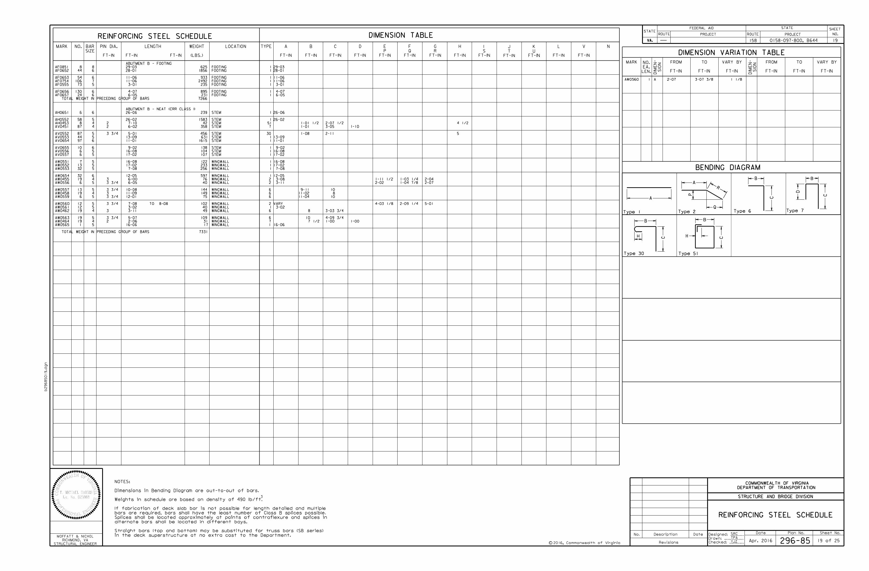
Date Plan No. Sheet No.Designed: ...........
Drawn: ................
Checked: ............2016, Commonwealth of Virginiac
No. Description Date
STRUCTURE AND BRIDGE DIVISION
COMMONWEALTH OF VIRGINIA
DEPARTMENT OF TRANSPORTATION
Revisions
ROUTE
FEDERAL AID
PROJECT ROUTE PROJECT
STATE SHEET
NO.
VA.
STATEROUTE
FEDERAL AID
PROJECT ROUTE PROJECT
STATE SHEET
NO.
VA.
STATE
REINFORCING STEEL SCHEDULE DIMENSION TABLE
MARK NO.
SIZE
BAR LOCATION TYPE N
(LBS.)
WEIGHT
BENDING DIAGRAM
DIMENSION VARIATION TABLE
MARK
LEN.
EA.
NO.
SIO
N
DIM
EN-
SIO
N
DIM
EN-
FT-IN
PIN DIA.
FT-IN FT-IN
LENGTH
FT-IN
A
FT-IN
B
FT-IN
C
FT-IN
D
FT-IN
P
E
FT-IN
Q
F
FT-IN
R
G
FT-IN
H
FT-IN
S
I
FT-IN
T
J
FT-IN
U
K
FT-IN
L
FT-IN
V
FT-IN
FROM
FT-IN
TO
FT-IN
VARY BY
FT-IN
FROM
FT-IN
TO
FT-IN
VARY BY
b29685019.d
gn
3
in the deck superstructure at no extra cost to the Department.
Straight bars (top and bottom) may be substituted for truss bars (SB series)
alternate bars shall be located in different bays.
Splices shall be located approximately at points of contraflexure and splices in
bars are required, bars shall have the least number of Class B splices possible.
If fabrication of deck slab bar is not possible for length detailed and multiple
Weights in schedule are based on density of 490 lb/ft.
Dimensions in Bending Diagram are out-to-out of bars.
NOTES:
STRUCTURAL ENGINEER
RICHMOND, VA
MOFFATT & NICHOLSRC
TPA
296-85 19 of 25
REINFORCING STEEL SCHEDULE
19158 0158-097-800, B644
Apr. 2016
Type 1
A
Type 2
Q
A
P
R
Type 6
C
B
Type 7
B
C
D
Type 30
H C
B
Type 51
B
H C
ABUTMENT B - FOOTING
29-03 29-03 625AF0851 8 8 1FOOTING
28-01 28-01 1856AF0652 44 6 1FOOTING
11-06 11-06 933AF0653 54 6 1FOOTING
11-06 11-06 2492AF0754 106 7 1FOOTING
3-01 3-01 235AF0555 73 5 1FOOTING
4-07 4-07 895AF0656 130 6 1FOOTING
6-05 6-05 231AF0657 24 6 1FOOTING
TOTAL WEIGHT IN PRECEDING GROUP OF BARS 7266
26-06 26-06 239AH0651 6 6 1STEM
26-02 26-02 1583AH0552 58 5 1STEM
1-01 1/2 2-07 1/2 4 1/2 7-10 42AH0453 8 4 2 51STEM
1-01 3-05 1-10 6-02 358AV0451 87 4 2 7STEM
1-08 2-11 5 5-01 456AV0552 87 5 3 3/4 30STEM
13-09 13-09 631AV0553 44 5 1STEM
11-01 11-01 1615AV0654 97 6 1STEM
9-02 9-02 138AV0655 10 6 1STEM
16-08 16-08 104AV0556 6 5 1STEM
17-02 17-02 107AV0557 6 5 1STEM
16-08 16-08 122AW0551 7 5 1WINGWALL
17-02 17-02 233AW0552 13 5 1WINGWALL
7-08 7-08 256AW0553 32 5 1WINGWALL
12-05 12-05 597AW0654 32 6 1WINGWALL
3-08 1-03 1/4 6-00 76AW0455 19 4 3 2WINGWALL
3-11 1-04 7/840AW0556 6 5 3 3/4 2WINGWALL
9-11 10 10-08 144AW0557 13 5 3 3/4 6WINGWALL
11-02 8 11-09 149AW0458 19 4 3 6WINGWALL
11-04 10 12-01 75AW0559 6 5 3 3/4 6WINGWALL
VARY 4-03 1/8 2-09 1/4 7-08 TO 8-08 102AW0560 12 5 3 3/4 2WINGWALL
AW0560 1 A 3-07 3/8 1 1/8
3-02 3-02 40AW0561 12 5 1WINGWALL
8 3-03 3/4 3-11 49AW0462 19 4 3 6WINGWALL
10 4-09 3/4 5-07 109AW0563 19 5 3 3/4 6WINGWALL
7 1/2 1-00 1-00 2-06 31AW0464 19 4 2 7WINGWALL
TOTAL WEIGHT IN PRECEDING GROUP OF BARS 7331
Type 1
A
Type 2
Q
A
P
R
Type 6
C
B
Type 7
B
C
D
Type 30
H C
B
Type 51
B
H C
YJZ
16-06 17AW0565 1 5 1WINGWALL 16-06
1-11 1/2 2-04
2-07
5-01
ABUTMENT B - NEAT (CRR CLASS I)
2-02 6-05
2-07
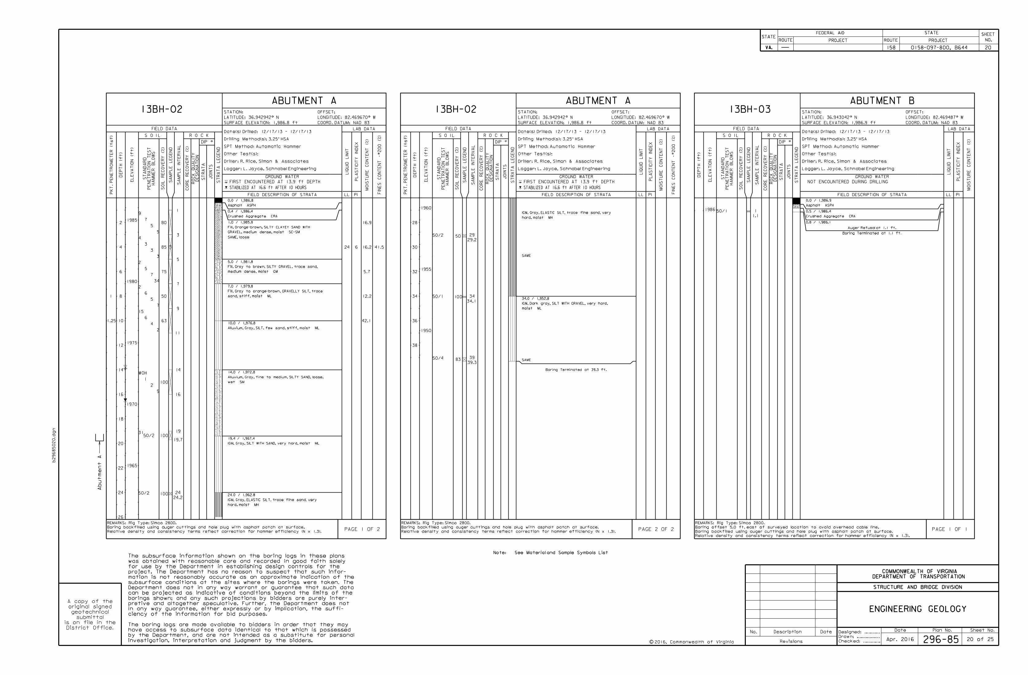
Date Plan No. Sheet No.Designed: ...........
Drawn: ................
Checked: ............2016, Commonwealth of Virginiac
No. Description Date
STRUCTURE AND BRIDGE DIVISION
COMMONWEALTH OF VIRGINIA
DEPARTMENT OF TRANSPORTATION
Revisions
ROUTE
FEDERAL AID
PROJECT ROUTE PROJECT
STATE SHEET
NO.
VA.
STATEROUTE
FEDERAL AID
PROJECT ROUTE PROJECT
STATE SHEET
NO.
VA.
STATE
b29685020.d
gn
ENGINEERING GEOLOGY
Note: See Material and Sample Symbols List
investigation, interpretation and judgment by the bidders.
by the Department, and are not intended as a substitute for personal
have access to subsurface data identical to that which is possessed
The boring logs are made available to bidders in order that they may
ciency of the information for bid purposes.
in any way guarantee, either expressly or by implication, the suffi-
pretive and altogether speculative. Further, the Department does not
borings shown; and any such projections by bidders are purely inter-
can be projected as indicative of conditions beyond the limits of the
Department does not in any way warrant or guarantee that such data
subsurface conditions at the sites where the borings were taken. The
mation is not reasonably accurate as an approximate indication of the
project. The Department has no reason to suspect that such infor-
for use by the Department in establishing design controls for the
was obtained with reasonable care and recorded in good faith solely
The subsurface information shown on the boring logs in these plans
District Office.
is on file in the
submittal
geotechnical
original signed
A copy of the
ABUTMENT A ABUTMENT A ABUTMENT B13BH-02 13BH-02 13BH-03
SURFACE ELEVATION: 1,986.8 ft
STATION:
COORD. DATUM: NAD 83
OFFSET:
SURFACE ELEVATION: 1,986.8 ft
STATION: OFFSET:
COORD. DATUM: NAD 83 COORD. DATUM: NAD 83
OFFSET:
SURFACE ELEVATION: 1,986.9 ft
STATION:
0.0 / 1,986.9
Asphalt ASPH
0.5 / 1,986.4
Crushed Aggregate CRA
0.8 / 1,986.1
Auger Refusal at 1.1 ft.
Boring Terminated at 1.1 ft.
50/1 1
1.1
GROUND WATER
FIELD DESCRIPTION OF STRATA
PAGE 1 OF 1
REMARKS: Rig Type: Simco 2800.
Boring offset 5.0 ft. east of surveyed location to avoid overhead cable line.
Boring backfilled using auger cuttings and hole plug with asphalt patch at surface.
Relative density and consistency terms reflect correction for hammer efficiency (N x 1.3).
Date(s) Drilled: 12/17/13 - 12/17/13
Drilling Method(s): 3.25" HSA
SPT Method: Automatic Hammer
Other Test(s):
Driller: R. Rice, Simon & Associates
Logger: L. Joyce, Schnabel Engineering
R O C K
1986
DEP
TH (ft)
NOT ENCOUNTERED DURING DRILLING
FIELD DATA
JOIN
TS
ST
RA
TA
LE
GE
ND
S O I L
EL
EV
ATIO
N (ft)
SA
MP
LE
LE
GE
ND
SA
MP
LE IN
TE
RV
AL
ST
RA
TA
RO
CK
QU
ALIT
YD
ESIG
NA
TIO
N
ST
AN
DA
RD
PE
NE
TR
ATIO
N
TES
T
HA
MM
ER
BL
OW
S
SOIL
RE
CO
VE
RY (%)
CO
RE
RE
CO
VE
RY (%)
PI
MOIS
TU
RE
CO
NT
EN
T (%)
PL
AS
TICIT
Y IN
DE
X
LIQ
UID
LIMIT
LL
LAB DATA
1
1.25
5
3
7
5
4
2
0.0 / 1,986.8
Asphalt ASPH
0.4 / 1,986.4
Crushed Aggregate CRA
1.0 / 1,985.8
Fill, Orange-brown, SILTY CLAYEY SAND WITH
GRAVEL, medium dense, moist SC-SM
SAME, loose
5.0 / 1,981.8
Fill, Gray to brown, SILTY GRAVEL, trace sand,
medium dense, moist GM
7.0 / 1,979.8
Fill, Gray to orange-brown, GRAVELLY SILT, trace
sand, stiff, moist ML
10.0 / 1,976.8
Alluvium, Gray, SILT, few sand, stiff, moist ML
14.0 / 1,972.8
Alluvium, Gray, fine to medium, SILTY SAND, loose,
wet SM
19.4 / 1,967.4
IGM, Gray, SILT WITH SAND, very hard, moist ML
24.0 / 1,962.8
IGM, Gray, ELASTIC SILT, trace fine sand, very
hard, moist MH
IGM, Gray, ELASTIC SILT, trace fine sand, very
hard, moist MH
SAME
34.0 / 1,952.8
IGM, Dark gray, SILT WITH GRAVEL, very hard,
moist ML
SAME
Boring Terminated at 39.3 ft.
80
85
75
50
63
100
100
100
50
100
83
5
3
34
7
2
5
9
4
2
2
15
WOH
31
50/2
50/2
50/1
50/4
7
3
5
6
6
1
50/2
1
3
5
7
9
11
14
16
19
19.7
24
24.2
29
29.2
34
34.1
39
39.3
41.5
16.9
16.2
5.7
12.2
42.1
24 6
GROUND WATER
FIELD DESCRIPTION OF STRATA
PAGE 1 OF 2
REMARKS: Rig Type: Simco 2800.
Boring backfilled using auger cuttings and hole plug with asphalt patch at surface.
Relative density and consistency terms reflect correction for hammer efficiency (N x 1.3).
PK
T.
PE
NE
TR
OM
ET
ER (t
sf)
Date(s) Drilled: 12/17/13 - 12/17/13
Drilling Method(s): 3.25" HSA
SPT Method: Automatic Hammer
Other Test(s):
Driller: R. Rice, Simon & Associates
Logger: L. Joyce, Schnabel Engineering
R O C K
1985
1980
1975
1970
1965
DEP
TH (ft)
FIRST ENCOUNTERED AT 13.9 ft DEPTH
STABILIZED AT 16.6 ft AFTER 10 HOURS
FIELD DATA
JOIN
TS
ST
RA
TA
LE
GE
ND
S O I LE
LE
VA
TIO
N (ft)
2
4
6
8
10
12
14
16
18
20
22
24
26
SA
MP
LE
LE
GE
ND
SA
MP
LE IN
TE
RV
AL
ST
RA
TA
RO
CK
QU
ALIT
YD
ESIG
NA
TIO
N
ST
AN
DA
RD
PE
NE
TR
ATIO
N
TES
T
HA
MM
ER
BL
OW
S
SOIL
RE
CO
VE
RY (%)
CO
RE
RE
CO
VE
RY (%)
FIN
ES
CO
NT
EN
T -#200 (%)
PI
MOIS
TU
RE
CO
NT
EN
T (%)
PL
AS
TICIT
Y IN
DE
X
LIQ
UID
LIMIT
LL
LAB DATA
GROUND WATER
FIELD DESCRIPTION OF STRATA
PAGE 2 OF 2
REMARKS: Rig Type: Simco 2800.
Boring backfilled using auger cuttings and hole plug with asphalt patch at surface.
Relative density and consistency terms reflect correction for hammer efficiency (N x 1.3).
PK
T.
PE
NE
TR
OM
ET
ER (t
sf)
Date(s) Drilled: 12/17/13 - 12/17/13
Drilling Method(s): 3.25" HSA
SPT Method: Automatic Hammer
Other Test(s):
Driller: R. Rice, Simon & Associates
Logger: L. Joyce, Schnabel Engineering
R O C K
1960
1955
1950
DEP
TH (ft)
FIRST ENCOUNTERED AT 13.9 ft DEPTH
STABILIZED AT 16.6 ft AFTER 10 HOURS
FIELD DATA
JOIN
TS
ST
RA
TA
LE
GE
ND
S O I L
EL
EV
ATIO
N (ft)
28
30
32
34
36
38
SA
MP
LE
LE
GE
ND
SA
MP
LE IN
TE
RV
AL
ST
RA
TA
RO
CK
QU
ALIT
YD
ESIG
NA
TIO
N
ST
AN
DA
RD
PE
NE
TR
ATIO
N
TES
T
HA
MM
ER
BL
OW
S
SOIL
RE
CO
VE
RY (%)
CO
RE
RE
CO
VE
RY (%)
FIN
ES
CO
NT
EN
T -#200 (%)
PI
MOIS
TU
RE
CO
NT
EN
T (%)
PL
AS
TICIT
Y IN
DE
X
LIQ
UID
LIMIT
LL
LAB DATA
Abut
me
nt
A
0158-097-800, B644 20158
296-85 20 of 25Apr. 2016
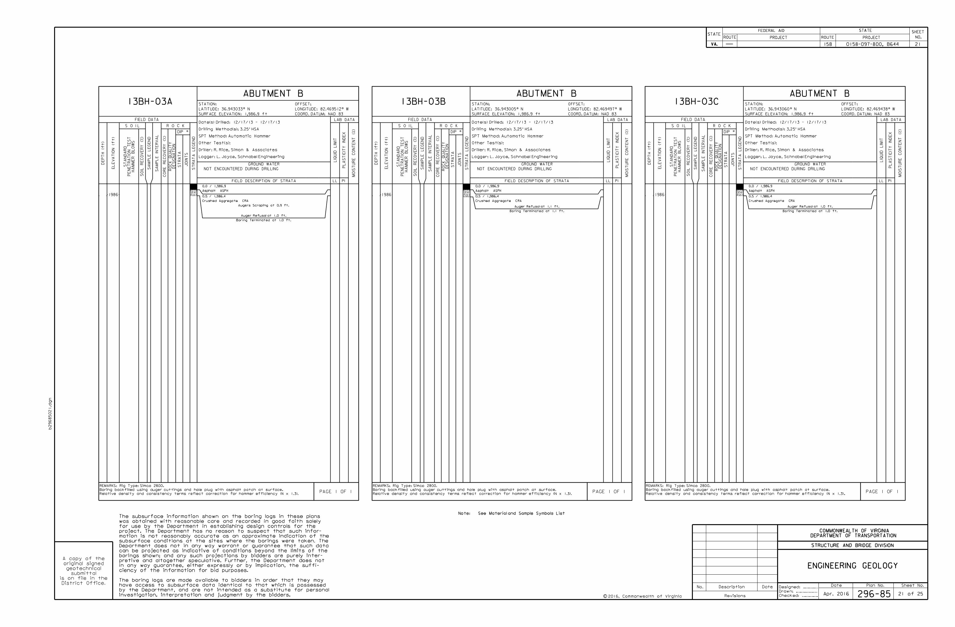
Date Plan No. Sheet No.Designed: ...........
Drawn: ................
Checked: ............2016, Commonwealth of Virginiac
No. Description Date
STRUCTURE AND BRIDGE DIVISION
COMMONWEALTH OF VIRGINIA
DEPARTMENT OF TRANSPORTATION
Revisions
ROUTE
FEDERAL AID
PROJECT ROUTE PROJECT
STATE SHEET
NO.
VA.
STATEROUTE
FEDERAL AID
PROJECT ROUTE PROJECT
STATE SHEET
NO.
VA.
STATE
b29685021.d
gn
ENGINEERING GEOLOGY
Note: See Material and Sample Symbols List
investigation, interpretation and judgment by the bidders.
by the Department, and are not intended as a substitute for personal
have access to subsurface data identical to that which is possessed
The boring logs are made available to bidders in order that they may
ciency of the information for bid purposes.
in any way guarantee, either expressly or by implication, the suffi-
pretive and altogether speculative. Further, the Department does not
borings shown; and any such projections by bidders are purely inter-
can be projected as indicative of conditions beyond the limits of the
Department does not in any way warrant or guarantee that such data
subsurface conditions at the sites where the borings were taken. The
mation is not reasonably accurate as an approximate indication of the
project. The Department has no reason to suspect that such infor-
for use by the Department in establishing design controls for the
was obtained with reasonable care and recorded in good faith solely
The subsurface information shown on the boring logs in these plans
District Office.
is on file in the
submittal
geotechnical
original signed
A copy of the
ABUTMENT B ABUTMENT B ABUTMENT B13BH-03A 13BH-03B 13BH-03C
COORD. DATUM: NAD 83
OFFSET:
SURFACE ELEVATION: 1,986.9 ft
STATION:
COORD. DATUM: NAD 83
OFFSET:
SURFACE ELEVATION: 1,986.9 ft
STATION:
COORD. DATUM: NAD 83
OFFSET:
SURFACE ELEVATION: 1,986.9 ft
STATION:
0.0 / 1,986.9
Asphalt ASPH
0.5 / 1,986.4
Crushed Aggregate CRA
Augers Scraping at 0.9 ft.
Auger Refusal at 1.0 ft.
Boring Terminated at 1.0 ft.
GROUND WATER
FIELD DESCRIPTION OF STRATA
PAGE 1 OF 1
REMARKS: Rig Type: Simco 2800.
Boring backfilled using auger cuttings and hole plug with asphalt patch at surface.
Relative density and consistency terms reflect correction for hammer efficiency (N x 1.3).
Date(s) Drilled: 12/17/13 - 12/17/13
Drilling Method(s): 3.25" HSA
SPT Method: Automatic Hammer
Other Test(s):
Driller: R. Rice, Simon & Associates
Logger: L. Joyce, Schnabel Engineering
R O C K
1986
DEP
TH (ft)
NOT ENCOUNTERED DURING DRILLING
FIELD DATA
JOIN
TS
ST
RA
TA
LE
GE
ND
S O I L
EL
EV
ATIO
N (ft)
SA
MP
LE
LE
GE
ND
SA
MP
LE IN
TE
RV
AL
ST
RA
TA
RO
CK
QU
ALIT
YD
ESIG
NA
TIO
N
ST
AN
DA
RD
PE
NE
TR
ATIO
N
TES
T
HA
MM
ER
BL
OW
S
SOIL
RE
CO
VE
RY (%)
CO
RE
RE
CO
VE
RY (%)
PI
MOIS
TU
RE
CO
NT
EN
T (%)
PL
AS
TICIT
Y IN
DE
X
LIQ
UID
LIMIT
LL
LAB DATA
0.0 / 1,986.9
Asphalt ASPH
0.5 / 1,986.4
Crushed Aggregate CRA
Auger Refusal at 1.1 ft.
Boring Terminated at 1.1 ft.
GROUND WATER
FIELD DESCRIPTION OF STRATA
PAGE 1 OF 1
REMARKS: Rig Type: Simco 2800.
Boring backfilled using auger cuttings and hole plug with asphalt patch at surface.
Relative density and consistency terms reflect correction for hammer efficiency (N x 1.3).
Date(s) Drilled: 12/17/13 - 12/17/13
Drilling Method(s): 3.25" HSA
SPT Method: Automatic Hammer
Other Test(s):
Driller: R. Rice, Simon & Associates
Logger: L. Joyce, Schnabel Engineering
R O C K
1986
DEP
TH (ft)
NOT ENCOUNTERED DURING DRILLING
FIELD DATA
JOIN
TS
ST
RA
TA
LE
GE
ND
S O I L
EL
EV
ATIO
N (ft)
SA
MP
LE
LE
GE
ND
SA
MP
LE IN
TE
RV
AL
ST
RA
TA
RO
CK
QU
ALIT
YD
ESIG
NA
TIO
N
ST
AN
DA
RD
PE
NE
TR
ATIO
N
TES
T
HA
MM
ER
BL
OW
S
SOIL
RE
CO
VE
RY (%)
CO
RE
RE
CO
VE
RY (%)
PI
MOIS
TU
RE
CO
NT
EN
T (%)
PL
AS
TICIT
Y IN
DE
X
LIQ
UID
LIMIT
LL
LAB DATA
0.0 / 1,986.9
Asphalt ASPH
0.5 / 1,986.4
Crushed Aggregate CRA
Auger Refusal at 1.0 ft.
Boring Terminated at 1.0 ft.
GROUND WATER
FIELD DESCRIPTION OF STRATA
PAGE 1 OF 1
REMARKS: Rig Type: Simco 2800.
Boring backfilled using auger cuttings and hole plug with asphalt patch at surface.
Relative density and consistency terms reflect correction for hammer efficiency (N x 1.3).
Date(s) Drilled: 12/17/13 - 12/17/13
Drilling Method(s): 3.25" HSA
SPT Method: Automatic Hammer
Other Test(s):
Driller: R. Rice, Simon & Associates
Logger: L. Joyce, Schnabel Engineering
R O C K
1986
DEP
TH (ft)
NOT ENCOUNTERED DURING DRILLING
FIELD DATA
JOIN
TS
ST
RA
TA
LE
GE
ND
S O I L
EL
EV
ATIO
N (ft)
SA
MP
LE
LE
GE
ND
SA
MP
LE IN
TE
RV
AL
ST
RA
TA
RO
CK
QU
ALIT
YD
ESIG
NA
TIO
N
ST
AN
DA
RD
PE
NE
TR
ATIO
N
TES
T
HA
MM
ER
BL
OW
S
SOIL
RE
CO
VE
RY (%)
CO
RE
RE
CO
VE
RY (%)
PI
MOIS
TU
RE
CO
NT
EN
T (%)
PL
AS
TICIT
Y IN
DE
X
LIQ
UID
LIMIT
LL
LAB DATA
0158-097-800, B644 21158
296-85 21 of 25Apr. 2016
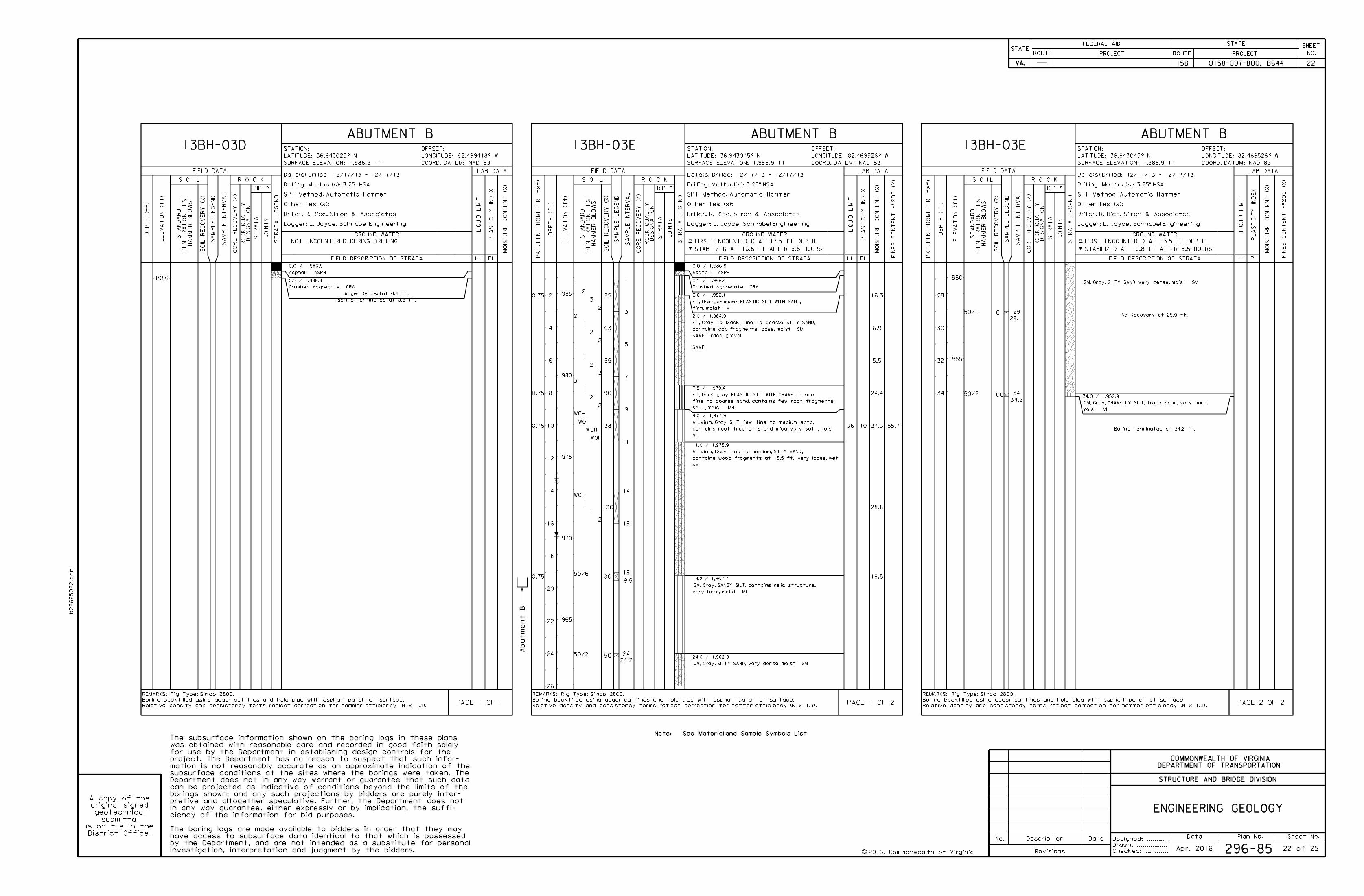
Date Plan No. Sheet No.Designed: ...........
Drawn: ................
Checked: ............2016, Commonwealth of Virginiac
No. Description Date
STRUCTURE AND BRIDGE DIVISION
COMMONWEALTH OF VIRGINIA
DEPARTMENT OF TRANSPORTATION
Revisions
ROUTE
FEDERAL AID
PROJECT ROUTE PROJECT
STATE SHEET
NO.
VA.
STATEROUTE
FEDERAL AID
PROJECT ROUTE PROJECT
STATE SHEET
NO.
VA.
STATE
b29685022.d
gn
ENGINEERING GEOLOGY
Note: See Material and Sample Symbols List
investigation, interpretation and judgment by the bidders.
by the Department, and are not intended as a substitute for personal
have access to subsurface data identical to that which is possessed
The boring logs are made available to bidders in order that they may
ciency of the information for bid purposes.
in any way guarantee, either expressly or by implication, the suffi-
pretive and altogether speculative. Further, the Department does not
borings shown; and any such projections by bidders are purely inter-
can be projected as indicative of conditions beyond the limits of the
Department does not in any way warrant or guarantee that such data
subsurface conditions at the sites where the borings were taken. The
mation is not reasonably accurate as an approximate indication of the
project. The Department has no reason to suspect that such infor-
for use by the Department in establishing design controls for the
was obtained with reasonable care and recorded in good faith solely
The subsurface information shown on the boring logs in these plans
District Office.
is on file in the
submittal
geotechnical
original signed
A copy of the
ABUTMENT B ABUTMENT B ABUTMENT B13BH-03D 13BH-03E 13BH-03E
COORD. DATUM: NAD 83
OFFSET:
SURFACE ELEVATION: 1,986.9 ft
STATION:
COORD. DATUM: NAD 83
OFFSET:
SURFACE ELEVATION: 1,986.9 ft
STATION:
COORD. DATUM: NAD 83
OFFSET:
SURFACE ELEVATION: 1,986.9 ft
STATION:
0.0 / 1,986.9
Asphalt ASPH
0.5 / 1,986.4
Crushed Aggregate CRA
Auger Refusal at 0.9 ft.
Boring Terminated at 0.9 ft.
GROUND WATER
FIELD DESCRIPTION OF STRATA
PAGE 1 OF 1
REMARKS: Rig Type: Simco 2800.
Boring backfilled using auger cuttings and hole plug with asphalt patch at surface.
Relative density and consistency terms reflect correction for hammer efficiency (N x 1.3).
Date(s) Drilled: 12/17/13 - 12/17/13
Drilling Method(s): 3.25" HSA
SPT Method: Automatic Hammer
Other Test(s):
Driller: R. Rice, Simon & Associates
Logger: L. Joyce, Schnabel Engineering
R O C K
1986
DEP
TH (ft)
NOT ENCOUNTERED DURING DRILLING
FIELD DATA
JOIN
TS
ST
RA
TA
LE
GE
ND
S O I L
EL
EV
ATIO
N (ft)
SA
MP
LE
LE
GE
ND
SA
MP
LE IN
TE
RV
AL
ST
RA
TA
RO
CK
QU
ALIT
YD
ESIG
NA
TIO
N
ST
AN
DA
RD
PE
NE
TR
ATIO
N
TES
T
HA
MM
ER
BL
OW
S
SOIL
RE
CO
VE
RY (%)
CO
RE
RE
CO
VE
RY (%)
PI
MOIS
TU
RE
CO
NT
EN
T (%)
PL
AS
TICIT
Y IN
DE
X
LIQ
UID
LIMIT
LL
LAB DATA
0.75
0.75
0.75
0.75
3
2
2
2
WOH
1
0.0 / 1,986.9
Asphalt ASPH
0.5 / 1,986.4
Crushed Aggregate CRA
0.8 / 1,986.1
Fill, Orange-brown, ELASTIC SILT WITH SAND,
firm, moist MH
2.0 / 1,984.9
Fill, Gray to black, fine to coarse, SILTY SAND,
contains coal fragments, loose, moist SM
SAME, trace gravel
SAME
7.5 / 1,979.4
Fill, Dark gray, ELASTIC SILT WITH GRAVEL, trace
fine to coarse sand, contains few root fragments,
soft, moist MH
9.0 / 1,977.9
Alluvium, Gray, SILT, few fine to medium sand,
contains root fragments and mica, very soft, moist
ML
11.0 / 1,975.9
Alluvium, Gray, fine to medium, SILTY SAND,
contains wood fragments at 15.5 ft., very loose, wet
SM
19.2 / 1,967.7
IGM, Gray, SANDY SILT, contains relic structure,
very hard, moist ML
24.0 / 1,962.9
IGM, Gray, SILTY SAND, very dense, moist SM
85
63
55
90
38
100
80
50
2
2
3
2
WOH
2
1
2
1
3
WOH
WOH
50/6
50/2
2
1
1
1
WOH
1
1
3
5
7
9
11
14
16
19
19.5
24
24.2
85.7
16.3
6.9
5.5
24.4
37.3
28.8
19.5
36 10
GROUND WATER
FIELD DESCRIPTION OF STRATA
PAGE 1 OF 2
REMARKS: Rig Type: Simco 2800.
Boring backfilled using auger cuttings and hole plug with asphalt patch at surface.
Relative density and consistency terms reflect correction for hammer efficiency (N x 1.3).
PK
T.
PE
NE
TR
OM
ET
ER (t
sf)
Date(s) Drilled: 12/17/13 - 12/17/13
Drilling Method(s): 3.25" HSA
SPT Method: Automatic Hammer
Other Test(s):
Driller: R. Rice, Simon & Associates
Logger: L. Joyce, Schnabel Engineering
R O C K
1985
1980
1975
1970
1965
DEP
TH (ft)
FIRST ENCOUNTERED AT 13.5 ft DEPTH
STABILIZED AT 16.8 ft AFTER 5.5 HOURS
FIELD DATA
JOIN
TS
ST
RA
TA
LE
GE
ND
S O I L
EL
EV
ATIO
N (ft)
2
4
6
8
10
12
14
16
18
20
22
24
26
SA
MP
LE
LE
GE
ND
SA
MP
LE IN
TE
RV
AL
ST
RA
TA
RO
CK
QU
ALIT
YD
ESIG
NA
TIO
N
ST
AN
DA
RD
PE
NE
TR
ATIO
N
TES
T
HA
MM
ER
BL
OW
S
SOIL
RE
CO
VE
RY (%)
CO
RE
RE
CO
VE
RY (%)
FIN
ES
CO
NT
EN
T -#200 (%)
PI
MOIS
TU
RE
CO
NT
EN
T (%)
PL
AS
TICIT
Y IN
DE
X
LIQ
UID
LIMIT
LL
LAB DATA
IGM, Gray, SILTY SAND, very dense, moist SM
No Recovery at 29.0 ft.
34.0 / 1,952.9
IGM, Gray, GRAVELLY SILT, trace sand, very hard,
moist ML
Boring Terminated at 34.2 ft.
0
100
50/1
50/2
29
29.1
34
34.2
GROUND WATER
FIELD DESCRIPTION OF STRATA
PAGE 2 OF 2
REMARKS: Rig Type: Simco 2800.
Boring backfilled using auger cuttings and hole plug with asphalt patch at surface.
Relative density and consistency terms reflect correction for hammer efficiency (N x 1.3).
PK
T.
PE
NE
TR
OM
ET
ER (t
sf)
Date(s) Drilled: 12/17/13 - 12/17/13
Drilling Method(s): 3.25" HSA
SPT Method: Automatic Hammer
Other Test(s):
Driller: R. Rice, Simon & Associates
Logger: L. Joyce, Schnabel Engineering
R O C K
1960
1955
DEP
TH (ft)
FIRST ENCOUNTERED AT 13.5 ft DEPTH
STABILIZED AT 16.8 ft AFTER 5.5 HOURS
FIELD DATA
JOIN
TS
ST
RA
TA
LE
GE
ND
S O I L
EL
EV
ATIO
N (ft)
28
30
32
34
SA
MP
LE
LE
GE
ND
SA
MP
LE IN
TE
RV
AL
ST
RA
TA
RO
CK
QU
ALIT
YD
ESIG
NA
TIO
N
ST
AN
DA
RD
PE
NE
TR
ATIO
N
TES
T
HA
MM
ER
BL
OW
S
SOIL
RE
CO
VE
RY (%)
CO
RE
RE
CO
VE
RY (%)
FIN
ES
CO
NT
EN
T -#200 (%)
PI
MOIS
TU
RE
CO
NT
EN
T (%)
PL
AS
TICIT
Y IN
DE
X
LIQ
UID
LIMIT
LL
LAB DATA
0158-097-800, B644 22158
296-85 22 of 25
Abut
me
nt
B
Apr. 2016
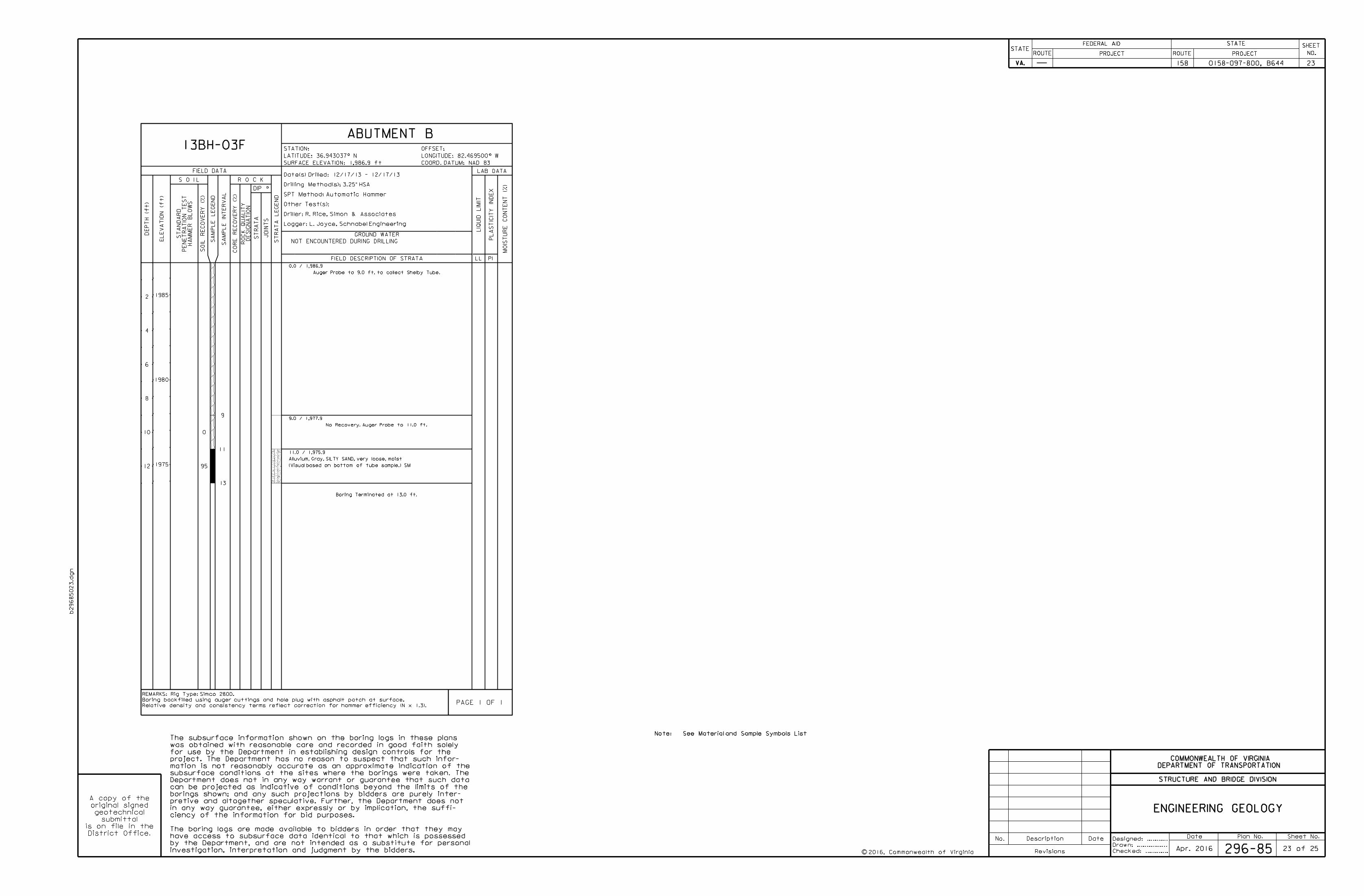
Date Plan No. Sheet No.Designed: ...........
Drawn: ................
Checked: ............2016, Commonwealth of Virginiac
No. Description Date
STRUCTURE AND BRIDGE DIVISION
COMMONWEALTH OF VIRGINIA
DEPARTMENT OF TRANSPORTATION
Revisions
ROUTE
FEDERAL AID
PROJECT ROUTE PROJECT
STATE SHEET
NO.
VA.
STATEROUTE
FEDERAL AID
PROJECT ROUTE PROJECT
STATE SHEET
NO.
VA.
STATE
b29685023.d
gn
ENGINEERING GEOLOGY
Note: See Material and Sample Symbols List
investigation, interpretation and judgment by the bidders.
by the Department, and are not intended as a substitute for personal
have access to subsurface data identical to that which is possessed
The boring logs are made available to bidders in order that they may
ciency of the information for bid purposes.
in any way guarantee, either expressly or by implication, the suffi-
pretive and altogether speculative. Further, the Department does not
borings shown; and any such projections by bidders are purely inter-
can be projected as indicative of conditions beyond the limits of the
Department does not in any way warrant or guarantee that such data
subsurface conditions at the sites where the borings were taken. The
mation is not reasonably accurate as an approximate indication of the
project. The Department has no reason to suspect that such infor-
for use by the Department in establishing design controls for the
was obtained with reasonable care and recorded in good faith solely
The subsurface information shown on the boring logs in these plans
District Office.
is on file in the
submittal
geotechnical
original signed
A copy of the
ABUTMENT B13BH-03F
COORD. DATUM: NAD 83
OFFSET:
SURFACE ELEVATION: 1,986.9 ft
STATION:
0.0 / 1,986.9
Auger Probe to 9.0 ft. to collect Shelby Tube.
9.0 / 1,977.9
No Recovery. Auger Probe to 11.0 ft.
11.0 / 1,975.9
Alluvium, Gray, SILTY SAND, very loose, moist
(Visual based on bottom of tube sample.) SM
Boring Terminated at 13.0 ft.
0
95
9
11
13
GROUND WATER
FIELD DESCRIPTION OF STRATA
PAGE 1 OF 1
REMARKS: Rig Type: Simco 2800.
Boring backfilled using auger cuttings and hole plug with asphalt patch at surface.
Relative density and consistency terms reflect correction for hammer efficiency (N x 1.3).
Date(s) Drilled: 12/17/13 - 12/17/13
Drilling Method(s): 3.25" HSA
SPT Method: Automatic Hammer
Other Test(s):
Driller: R. Rice, Simon & Associates
Logger: L. Joyce, Schnabel Engineering
R O C K
1985
1980
1975
DEP
TH (ft)
NOT ENCOUNTERED DURING DRILLING
FIELD DATA
JOIN
TS
ST
RA
TA
LE
GE
ND
S O I L
EL
EV
ATIO
N (ft)
2
4
6
8
10
12
SA
MP
LE
LE
GE
ND
SA
MP
LE IN
TE
RV
AL
ST
RA
TA
RO
CK
QU
ALIT
YD
ESIG
NA
TIO
N
ST
AN
DA
RD
PE
NE
TR
ATIO
N
TES
T
HA
MM
ER
BL
OW
S
SOIL
RE
CO
VE
RY (%)
CO
RE
RE
CO
VE
RY (%)
PI
MOIS
TU
RE
CO
NT
EN
T (%)
PL
AS
TICIT
Y IN
DE
X
LIQ
UID
LIMIT
LL
LAB DATA
0158-097-800, B644 23158
296-85 23 of 25Apr. 2016
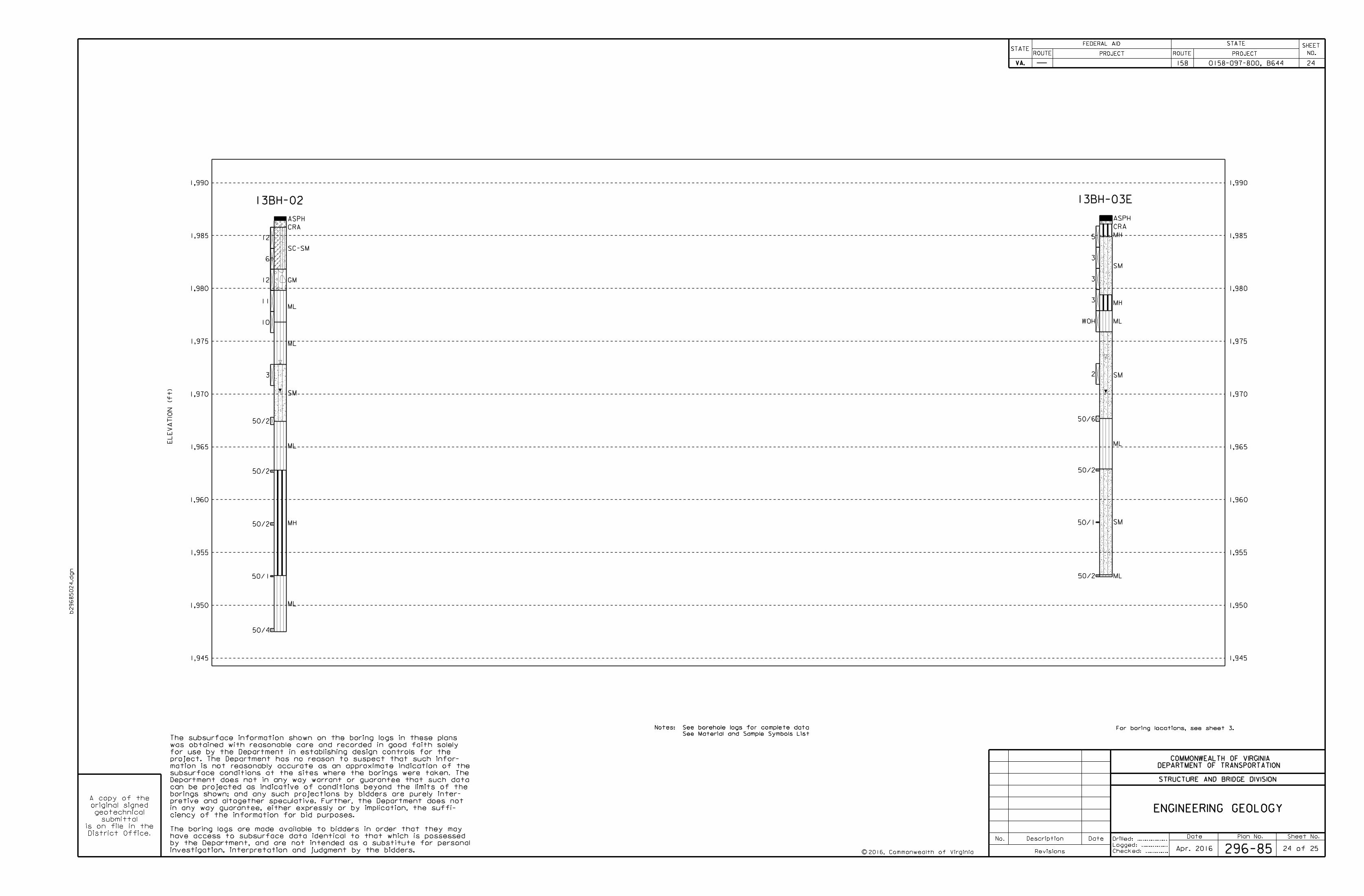
Date Plan No. Sheet No.
Checked: ............2016, Commonwealth of Virginiac
No. Description Date
STRUCTURE AND BRIDGE DIVISION
COMMONWEALTH OF VIRGINIA
DEPARTMENT OF TRANSPORTATION
Revisions
ROUTE
FEDERAL AID
PROJECT ROUTE PROJECT
STATE SHEET
NO.
VA.
STATEROUTE
FEDERAL AID
PROJECT ROUTE PROJECT
STATE SHEET
NO.
VA.
STATE
b29685024.d
gn
ENGINEERING GEOLOGY
investigation, interpretation and judgment by the bidders.
by the Department, and are not intended as a substitute for personal
have access to subsurface data identical to that which is possessed
The boring logs are made available to bidders in order that they may
ciency of the information for bid purposes.
in any way guarantee, either expressly or by implication, the suffi-
pretive and altogether speculative. Further, the Department does not
borings shown; and any such projections by bidders are purely inter-
can be projected as indicative of conditions beyond the limits of the
Department does not in any way warrant or guarantee that such data
subsurface conditions at the sites where the borings were taken. The
mation is not reasonably accurate as an approximate indication of the
project. The Department has no reason to suspect that such infor-
for use by the Department in establishing design controls for the
was obtained with reasonable care and recorded in good faith solely
The subsurface information shown on the boring logs in these plans
District Office.
is on file in the
submittal
geotechnical
original signed
A copy of the
0158-097-800, B644 24158
296-85 24 of 25
Drilled: ................
Logged: ..............
Notes: See borehole logs for complete data
See Material and Sample Symbols List
For boring locations, see sheet 3.
1,945
1,950
1,955
1,960
1,965
1,970
1,975
1,980
1,985
1,990
1,945
1,950
1,955
1,960
1,965
1,970
1,975
1,980
1,985
1,990
ASPH
CRA
SC-SM
GM
ML
ML
SM
ML
MH
ML
12
6
12
11
10
3
50/2
50/2
50/2
50/1
50/4
13BH-02
ASPH
CRA
MH
SM
MH
ML
SM
ML
SM
ML
5
3
3
3
WOH
2
50/6
50/2
50/1
50/2
13BH-03E
EL
EV
ATIO
N (ft)
Apr. 2016
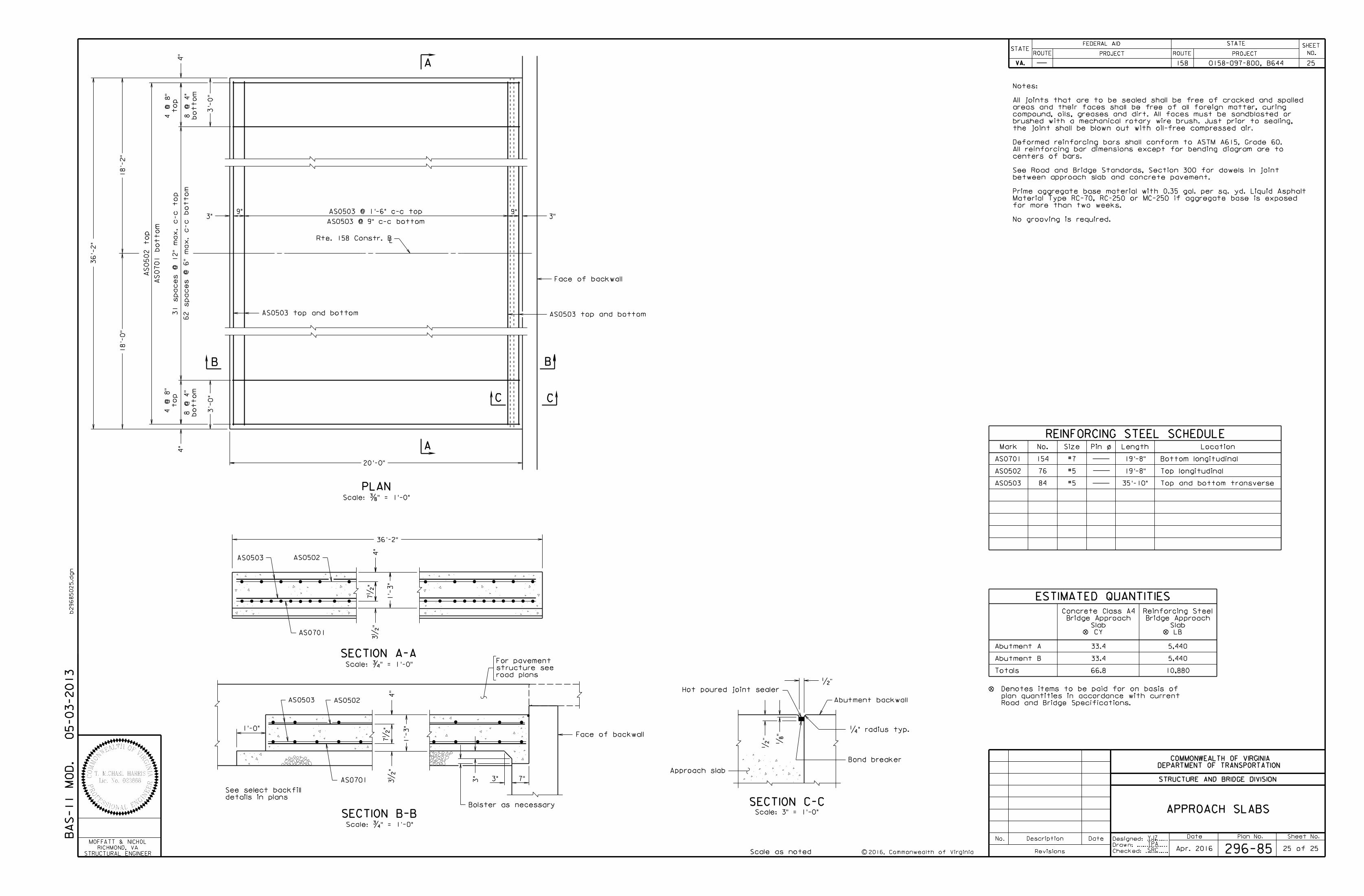
PLAN
APPROACH SLABS
Scale: …" = 1'-0"
Scale as noted
05-03-2013
Date Plan No. Sheet No.Designed: ...........
Drawn: ................
Checked: ............2016, Commonwealth of Virginiac
No. Description Date
STRUCTURE AND BRIDGE DIVISION
COMMONWEALTH OF VIRGINIA
DEPARTMENT OF TRANSPORTATION
Revisions
ROUTE
FEDERAL AID
PROJECT ROUTE PROJECT
STATE SHEET
NO.
VA.
STATEROUTE
FEDERAL AID
PROJECT ROUTE PROJECT
STATE SHEET
NO.
VA.
STATE
b29685025.d
gn
158 250158-097-800, B644
YJZ
TPA
296-85 25 of 25
36'-
2"
BA
S-11
MO
D.
STRUCTURAL ENGINEER
RICHMOND, VA
MOFFATT & NICHOL
20'-0"
3'-
0"
4"
3"9" 9"
3"
Face of backwall
A
BB
A
CC
3'-
0"
4"
AS0502 to
p
AS0701 botto
m
AS0503 @ 1'-6" c-c top
AS0503 @ 9" c-c bottom
botto
m
8
@ 4"
to
p
4
@ 8"
botto
m
8
@ 4"
to
p
4
@ 8"
AS0503 top and bottom AS0503 top and bottom
Bolster as necessary
Face of backwall
SECTION A-A
SECTION B-B
1'-
3"
4"
3"
3" 7"
AS0503 AS0502
AS0701
AS0701
AS0503 AS0502
4"
1'-
3"
Hot poured joint sealer
Scale: 3" = 1'-0"
SECTION C-C
Bond breaker
Approach slab
Abutment backwall
•"
„"
•"
‚" radius typ.
7•
"
7•
"
Scale: ƒ" = 1'-0"
Scale: ƒ" = 1'-0"
3•
"
3•
"
details in plans
See select backfill
Mark
AS0701
AS0502
AS0503
No. Length
19'-8"
19'-8"
Location
REINFORCING STEEL SCHEDULE
Bottom longitudinal
Top longitudinal
Size Pin o/
Top and bottom transverse
Totals
ESTIMATED QUANTITIES
Abutment A
Abutment B
Road and Bridge Specifications.
plan quantities in accordance with current
Denotes items to be paid for on basis of
#7
#5
#5
LB
Slab
Bridge Approach
Reinforcing Steel
CY
Slab
Bridge Approach
Concrete Class A4
76
84
Apr. 2016
No grooving is required.
for more than two weeks.
Material Type RC-70, RC-250 or MC-250 if aggregate base is exposed
Prime aggregate base material with 0.35 gal. per sq. yd. Liquid Asphalt
between approach slab and concrete pavement.
See Road and Bridge Standards, Section 300 for dowels in joint
centers of bars.
All reinforcing bar dimensions except for bending diagram are to
Deformed reinforcing bars shall conform to ASTM A615, Grade 60.
the joint shall be blown out with oil-free compressed air.
brushed with a mechanical rotary wire brush. Just prior to sealing,
compound, oils, greases and dirt. All faces must be sandblasted or
areas and their faces shall be free of all foreign matter, curing
All joints that are to be sealed shall be free of cracked and spalled
Notes:
33.4
33.4
66.8
5,440
5,440
10,880
31 spaces
@ 12"
max.
c-c to
p
62 spaces
@ 6"
max.
c-c botto
m
36'-2"
road plans
structure see
For pavement
154
SRC
1'-0"
35'-10"
Rte. 158 Constr. BL
18'-
0"
18'-
2"


![TRANSPORTATION SERVICE AGREEMENT FOR FIRM TRANSPORTATION ... · Page 1 of 21 Transportation Service Agreement [Shipper] TRANSPORTATION SERVICE AGREEMENT FOR FIRM TRANSPORTATION OF](https://img.pdfslide.net/doc/110x75/5ae2498c7f8b9ad47c8ceb10/transportation-service-agreement-for-firm-transportation-1-of-21-transportation.jpg)