Embed Size (px)
Citation preview

P a g e | 1
DEPARTMENT OF TRANSPORTATION SPECIFICATIONS
5-16-2019
TRUCK CAB & CHASSIS, QUAD AXLE, DUMP BODY, CENTRAL HYDRAULICS Delivery Locations and Instructions Page 2 Common Requirements Page 4 Pilot Model Inspection Page 9 Warranty Page 10 Delivery Page 14 Truck Cab & Chassis Page 15 Dump Body Page 25 Warranty - Dump Body Page 45 Road Temperature Monitoring System Page 45 Central Hydraulic System Page 46 Parts & Service – Central Hydraulic Systems Page 62 Warranty - Central Hydraulic System Page 63 Material Spreader Page 63
P a g e | 2
MANUFACTURER’S STATEMENT OF ORGIN SHALL BE EXECUTED TO ORDERING AGENCY AS SHOWN ON PURCHASE ORDER. ALL INFORMATION, INCLUDING INVOICES, MSO’S, ETC., CONCERNING EACH UNIT SHALL BE SENT TO THE APPROPRIATE DELIVERY LOCATION AS SHOWN ON PURCHASE ORDER. NOTE: Ordering agency shall provide the contract holder with contact names and phone numbers of key personnel for purchasing and final F.O.B. destination of units ordered.
SPECIAL INSTRUCTIONS: Unit delivered as a result of this advertisement must meet all requirements of these specifications. All bidders are expected to quote upon a manufacturer's latest standard conventional model truck complete with all standard equipment plus any optional or special equipment required for specification compliance. All cab and chassis dimensions shall be from manufacturer’s standard base model dimensions, excluding front frame extensions, as shown in OEM’s printed or electronic data. Unit dimensions shall not be altered after assembly and delivery to dealer in order to comply with the written specifications. Specifications include a cab & chassis; dump body with hoist, complete central hydraulic system, snow plow push frame, and v-box spreaders installed and meeting all requirements of these specifications. Successful bidder whose name shall appear on purchase order shall be solely responsible for meeting written specifications. Truck vendor is cautioned if any frame mounted attachments such as air dryers, batteries, fuel tanks, etc. requiring relocation shall be relocated, costs associated with the re-location will be at the expense of the successful bidder. It shall be the sole responsibility of each truck vendor to provide information to body manufacturers about size, shape, capacity and availability of front frame ends, so body manufacturers can determine particular truck brand needs for mounting snowplow push frame and can price accordingly for completed unit. It is the bidder’s responsibility to supply completed unit to the State of Tennessee. It is the responsibility of truck vendor to provide body manufacturer with factory engineer drawings prior to the bid for proper pricing of body and components. It shall be the responsibility of the contract holder to inspect the completed unit for specification compliance prior to delivery to the State of Tennessee F.O.B. delivery location(s).
P a g e | 3
REQUIRED All bidders must provide the following documentation with their bid in order to be considered for award:
A. All bidders must submit literature that substantiates that the products bid meet or exceeds all specifications. Literature must be submitted with bid. A detailed line item manufacturer’s build sheet must be submitted with the bid as well.
B. Bids must include a vendor listing of all items to be provided on the chassis, and specifications for equipment to be provided by the body vendor.
C. Bids must include a full set of engineering drawings showing the following;
a. dump body b. hoist c. hoist mounting d. chassis layout and location of all other components that are
provided by dump body vendor.
OPTIONAL EQUIPMENT A non-bid line item shall be included in this contract for truck manufacturer, body builder, and dealer options. All truck manufacturer options shall be available as part of this contract at dealer cost. Documentation of dealer cost from manufacturer shall be submitted upon request and with invoice. Requested options shall be submitted with purchase order.
STANDARD SPECIFICATIONS
The successful bidder shall hereafter be referred to as the “contract holder.” The outfitter or installer of all non-chassis manufacturer installed components shall hereafter be referred to as the “body builder.” This specification is designed to provide the state with efficient and dependable quad-axle trucks for maintenance operations. Their use will include material hauling, trailer towing, and operation of hydraulically controlled snowplows, a material spreader and a herbicide spray unit. Each truck shall be complete with all standard equipment, plus any optional or special equipment to meet the complete specifications as stated in this bid. Each truck shall be fully operational, with all mechanical adjustments made prior to delivery. The hydraulic system shall be fully functional prior to delivery. Base settings for the hydraulic/spreader controls shall be entered into all units. Pounds per lane mile of granular material that is to be entered into base settings shall be provided by the state prior to installation of spreader control.
P a g e | 4
For each truck: 1. All chassis, body, component, and snow equipment grease fittings shall be
lubricated per manufacturer’s specifications prior to delivery. 2. Each truck shall be equipped with all safety components that are required by the
current Federal Motor Vehicle Safety Standards to include fire extinguisher and safety triangles. Extinguisher shall be minimum 5-lb. maximum 8-lb ABC rated and shall be mounted inside cab of truck with latching vehicle style bracket.
3. Each truck shall also comply with all vehicle weight, dimension, and safety requirements of the State of Tennessee.
4. The contract holder shall provide specific information for the lubricants and coolant required by the complete chassis. This information shall include an ASTM, TMC, or MIL. Spec number for the following items: A. Engine Oil B. Engine Coolant C. Power Steering Fluid D. Transmission Fluid E. Rear Axle Lubricant F. Chassis Lubricant G. Driveline Lubricant H. Hydraulic Fluid
Fabrication of components and installation of systems must be performed in the body builder’s own shop, or other facility which shall be pre-approved by the state. Certain options are cause for chassis specification changes. It is advised that prospective chassis vendors review the entire specification, including the Optional Equipment sections. All items not specifically listed in this specification, but necessary for proper and efficient operation of this unit, must be supplied and included in the bid price.
COMMON REQUIREMENTS
The following specifications shall apply to common requirements for all components included in the purchase package of all completed trucks, including optional equipment. Included are requirements for the following items:
1. Approved Equal Requests 2. Manuals and Service Publications 3. Paint 4. Pilot Inspections 5. Pre-Delivery Inspection 6. Warranty 7. Training
P a g e | 5
1. APPROVED EQUAL REQUESTS
A. All specified chassis equipment is to be OEM installed, either as standard equipment, a line installed option or factory authorized DSO/SE installation unless otherwise specifically stated.
B. Any items that are not available as chassis OEM installations, and/or any other component, installation, item, or equipment that a vendor wishes to bid differently than requested in these specifications must be listed clearly on an attached sheet, and will require pre-approval from the state. Any literature, technical data and/or other ‘proof’ needed to support such a request shall be included.
C. Items requiring pre-approval are to be submitted no later than one week after pre-bid conference is held. Some items requiring pre-approval may also require subsequent approval at the pilot inspection.
D. Final approval of any vendor or manufacturer's equipment may require a demonstration, current user list, and/or tour of their facility to determine compliance and acceptability. Vendors shall make available, upon request and no later than one week after pre-bid conference any or all of the following:
i. Demonstration - A typical and similar same model machine and/or
component shall be provided to the state for up to two working days of unimpeded evaluation. A physical use demonstration may be conducted if applicable at a state Facility. Equipment will be operated by state personnel.
ii. Contact List – The name, address, and telephone number of other customers using the same equipment that can be contacted and a visit arranged.
iii. Facility Tour – Vendor shall provide a list of suitable times to the state within regular daytime work hours when an inspection tour of their installation and/or manufacturing facility would be convenient.
iv. Drawings – Equipment vendors are to supply with the proposal, a full set of drawings depicting the equipment they intend to supply.
E. Inability to comply with any or all will be adequate reason for bid rejection.
2. MANUALS AND SERVICE PUBLICATIONS/SOFTWARE
Publications in paper format must be bound into manuals or installed in binders when delivered to ordering agency; boxed, shrink-wrapped or otherwise unbound loose pages are not acceptable.

P a g e | 6
A. Operator Manuals A complete set of operator manuals shall be furnished with each completed truck. i. A complete set of standard Operator Manuals for the chassis,
engine, transmission, and all OEM installed components shall be furnished with each completed truck.
ii. A complete set of Operator Manuals for all Body Builder-installed components shall be provided with each completed truck.
B. Service Manuals
i. Chassis
Service manuals are to include TSB’s, diagnostic and repair procedures for all OEM installed components including, but not limited to, the chassis, engine, electronic engine controls, fuel system, emissions system, electrical system including all controllers, transmission, axles, and HVAC.
a. On-Line Version – An on-line service system, comparable to those available to dealerships, shall be provided, with accessibility for 50 concurrent state users. The state must pre-approve on-line systems.
b. USB/CD Version – USB/CD version of the same On-Line service manuals that are available to dealerships. If updates are available the ordering agency shall receive an updated USB/CD version approximately 4 – times per year and shall include all truck models in this specification purchased on contract. The ordering agency shall receive these USB/CD updates during the term of the contract.
ii. Body Builder-Installed Components Shop service manuals shall be provided for each body, hydraulic system and electric system. Manuals shall consist of but not be limited to, complete schematic drawings and replaceable parts, brand names and part numbers of body, hoist, tailgate latch, hardware, snowplow hitch frame, plow cylinder, hydraulic tank and complete central hydraulic system, as installed with manufacturer and model number of all hydraulic valves and components. Manuals may be in book or electronic format. Manuals shall be provided with each completed truck.
1. Each add-on electrical accessory circuit shall have its own circuit diagram, showing the complete power and ground sides, routing, wire color and gauge, pin numbers, switches, breaker or fuse location and/or number, and specific ground point locations.
P a g e | 7
2. Each add-on air powered accessory circuit shall have its own circuit diagram, showing valve location, air line color, air line size, and routing.
3. A complete hydraulic schematic of all accessory circuits, including flow specifications and pressure settings for relief valves on each circuit.
4. For each hydraulic hose installed, the diameter and overall length of the hose, including both fittings, and the type and size of each fitting.
C. Parts Manuals
i. Chassis On-line– An on-line parts catalog system, comparable to those available to dealerships, shall be provided, with accessibility for 50 concurrent users. Parts system shall be complete for all OEM-installed components, including but not limited to, the chassis, engine, electronic engine controls, fuel system, emissions system, electrical system including all controllers, transmission, axles, and HVAC. The state must pre-approve the on-line system.
ii. Body Builder-Installed Components
Manuals shall be complete for all Body Builder-installed components, including but not limited to, the hydraulic system, the electric system, spreader control system, warning light system, material spreaders, and underbody plows. Paper Copies – A VIN-number specific manual shall be supplied with each completed truck. This manual shall include:
1. Make and model of all Body Builder-installed components. 2. Complete, fully illustrated parts listing for all Body Building-
installed components.
D. Line Sheet
Each completed truck shall be delivered with a factory line sheet listing all chassis component codes as installed by the chassis manufacturer. An electronic version may be substituted in lieu of paper copies. The state must pre-approve on-line versions.
P a g e | 8
3. PAINT
Finish shall be smooth, shiny, and free of runs, overspray, and/or other defects. ** NO bare ferrous metal components shall be visible on the chassis, or any OEM or Body Builder-installed components.** A. Truck Cab and Chassis
i. Truck cab shall be painted with a two-step factory base coat, clear
coat process. ii. Cab paint color shall be: Factory White. iii. Frame and undercarriage shall be completely painted with a high
quality black single-step finish to provide maximum corrosion protection.
B. Body-Builder-Installed Components
i. All manufactured ferrous equipment attached to the chassis shall have all mill scale, oils, dirt, rust, shipping primer and/or other contaminants removed from the steel surfaces, then, thoroughly cleaned. This may be accomplished by sand or media blasting or other methods. This shall include at a minimum the front plow hitch; dump body, any wing plow or underbody scraper, valve enclosures, reservoir, and any other components that are subject to corrosion.
ii. Paints and primers used shall be 100% lead and chromate free. MSDS on products used shall be made immediately available to TDOT upon request.
iii. All components shall be painted with a premium quality Polysiloxane corrosion resistant finish, consisting of minimum 2 mils dry film build corrosion resistant epoxy primer top coated with2-3 mils dry film build Polysiloxane corrosion resistant finish paint. Minimum finished application thickness, 4 mils dry film build.
iv. All visible finishes shall be smooth, shiny, and free of runs, overspray, and/or other defects.
v. Body accessories that are required to be welded on, i.e., ladders, steps, tarp brackets, warning light brackets, cab shield, etc., are to be installed by the Body Builder prior to priming.
vi. Upon completion of component installation, the Body Builder shall touch-up factory chassis paint damaged during component installation.
vii. Colors: All components used in the fabrication of a TDOT truck that are required to be painted shall be painted Gloss Black Polysiloxane corrosion resistant paint. These components include, but are not limited to, dump body, attachments to the dump body, and hydraulic oil reservoir.
P a g e | 9
4. PILOT MODEL INSPECTIONS IMPORTANT INFORMATION REGARDING PILOT MODEL The state of Tennessee is aware that various truck cab-chassis configurations, engine-transmission types and exhaust systems will greatly influence the location of required body and hydraulic equipment. For these reasons, the state reserves the right to approve the location of all dump body and hydraulic equipment. The state requires a completed pilot model with spreader, snowplow and all hydraulics installed and in complete working order be made available within approximately 30 calendar days after receipt of cab and chassis. Manual package shall be included with pilot model. The completed pilot model shall be delivered to the ordering agency for inspection and approval purposes prior to production of the remaining order. An address will be provided at time of order. All hydraulic functions will be tested during inspection. Snowplow will be furnished by the State of Tennessee during pilot model inspection at the above F.O.B. delivery location. Final inspection and acceptance of all other units will be made at each F.O.B. delivery location.
A. Vendor shall notify the state upon completion of the pilot chassis. Discrepancies and/or findings of non-compliance will be listed and must be corrected and/or addressed to the satisfaction of the state before the rest of the chassis are built.
5. PRE-DELIVERY INSPECTION A. Vendor/Body Builder
Upon completion, the Vendor and/or Body Builder shall do a thorough pre-delivery inspection of each completed truck to include the chassis and all installed components and snow equipment. Inspection shall be customized to reflect snow removal truck requirements, including but not limited to: hydraulic system individual pressure settings, hydraulic controls operation, spreader control system operation, pre-wet, and underbody scraper operation, dump bed and tailgate operation, tarp system, warning lights, hydraulic hose and electrical wire routing and protection. Inspection results shall be recorded on a pre-printed form (see attachment). A copy of this inspection, signed and dated by the performing technician and the Quality Control inspector, shall be placed in the document packet delivered with each truck.
B. State of Tennessee
P a g e | 10
The state reserves the right to complete a thorough pre-delivery inspection of each completed truck at the final assembly point. This inspection will include the chassis and all installed components and snow equipment. Contract holder shall provide to the ordering agency, a weekly production list, a planned delivery schedule and a list of completed vehicles deliveries to ordering agencies.
6. WARRANTY
If any standard retail warranty exceeds these minimum terms, the standard warranty shall apply. Information on such warranties shall be submitted to the ordering agency.
A. Truck Chassis
i. The chassis manufacturer shall guarantee to furnish all warranty services gratis at franchised dealers within the State of Tennessee.
ii. From the state “in service date” of the completed truck, the manufacturer and/or its representative shall provide the standard manufacturer’s warranty.
B. Snow Removal Equipment
From the date that the ordering agency assigns this equipment to its requesting location, the manufacturer and/or its representative shall provide a no-deductible, all-inclusive warranty (less normal maintenance) for a minimum of one year.
C. Body Builder-Manufactured/Installed Components From the date that the ordering agency assigns the completed truck to its
requesting location, the Body Builder shall provide a no-deductible, all-inclusive warranty (less normal maintenance) guaranteeing the design, material, installation, and workmanship of the completed unit and all installed components for a minimum of one year. LED warning light system warranty shall be for a period of five years.
The body builder shall provide a list of authorized repair stations that will
perform warranty repairs on all Body Builder-installed components on the truck.
Supplier Name____________________________________________
P a g e | 11
Street Address___________________________________________ City____________________________________________________ Contact Person___________________________________________ Phone Number___________________________________________ An additional copy of all warranties shall be sent to ordering agency bill to
location listed on the purchase order. 7. ON SITE TRAINING
The contract holder, in cooperation with the body and hydraulic system supplier, shall provide training to the ordering agency as described below. All training content and scheduling shall be coordinated through the ordering agency. The contract holder, in cooperation with body and hydraulic system supplier, shall provide technical training for all components of the complete truck. All costs for instructors and materials are the responsibility of the contract holder. Contract holder shall collaborate with the ordering agency to provide the necessary training for the completed truck; including diesel particulate filter regeneration, and all body builder-installed components. Ordering agency shall approve the content of this material. Contract holder, at his expense, shall provide ordering agency completed training materials within 60 days of contract award and conduct a mock training session for final approval of content. All training shall be performed by factory/company designated trainers. Ordering agency shall verify trainer credentials. Annual training shall be provided for each model year vehicle that is purchased from this contract, covering all areas of the complete truck. Training will only be conducted at each district/sub-district that receive a vehicle.
Training will include classroom & hands-on instruction on all features, accessories, and functions of the truck including body & hydraulics.
A. Operator
1. Cab & chassis training shall be conducted at each district headquarter
facility and sub-district office (22 locations). Body builder installed component training shall be conducted at each sub-district facility (22 locations).
2. Operator training for the cab and chassis shall last approximately 3.5 hours and shall include but not limited to the proper operation of all standard and
P a g e | 12
optional manufacturer/dealer installed items to include explanation of all warning lights and buzzers, location of all fluid check points and types of fluid, proper method of checking all fluid levels and the proper exhaust regeneration procedures.
3. Operator training for the body builder components shall last approximately 3.5 hours and shall include but not limited to the proper operation of all body builder installed components to include snow plows, spreaders, hydraulic systems, bed system and all safety lights.
4. Cab and chassis training shall not be combined in the same 3.5 hours as the body builder installed components.
5. All operators shall receive a step by step copy of the operation of the spreader control system.
6. Trainers shall provide a minimum of ten (10) ground speed controllers or simulators of the exact model installed in the trucks for hands-on classroom training.
7. Trainers shall include a step by step power point presentation of the operation of the ground speed controller system.
B. Mechanics
1. The contract holder shall provide training for the listed critical areas.
Each training session (cab /chassis and the body builder installed component) for mechanics shall last no less than 3.5 hours. Cab/chassis and body builder training shall not be combined in the same session.
a. Course content shall be tailored to meet the specific needs
of mechanics, and shall not place emphasis on areas or components not specified in these specifications. Course shall also include as much hands-on content as needed to reinforce lecture content.
b. The contract holder shall provide telephone numbers and name of contact person/persons for technical assistance to mechanics on all major components on the completed truck. Contact person/persons for body builder installed components and the ground speed controller/hydraulic system shall be available 24 hours a day, October 1st through April 30th.
c. Mechanic cab and chassis training shall be conducted at each sub-district facility (22 locations). Body builder installed component training shall be conducted at each sub-district facility (22 locations).
P a g e | 13
d. All mechanics shall receive a step by step copy of the operation of the spreader control system.
e. All mechanics shall receive a step by step trouble shooting copy of the spreader control/hydraulic system
f. Calibration training of the ground speed control system shall be hands on training with a step by step list of the calibration process for both granular and pre-wet systems.
g. Trainers shall provide a minimum of ten (10) ground speed controllers/simulators of the exact model installed in the trucks for operator, mechanic and calibration training.
2. Critical Areas
a. Cab and Chassis Systems
i. Operation of all standard and optional supplied equipment. ii. Proper lubrication and fluid inspection to include types of
fluids, inspection points and filter locations. iii. Proper preventative maintenance procedures. iv. Location of all fuse boxes, circuit breakers and all
electrical/control modules ie: TCMs, ECMs, ABS modules etc. and any maintenance/preventative maintenance for these items.
v. The meaning of all SES/system malfunction lights, proper procedures when illuminated and any resets allowed.
vi. Proper brake inspection and maintenance. vii. Proper regeneration procedures of exhaust systems.
b. Body Builder-Installed Components
I. Hydraulic system operation, diagnostics and repair. II. Electrical accessories operation, circuits, diagnostics and
repair. III. Spreader control system operation, diagnostics and repair. IV. Warning light system operation, diagnostics and repair V. Ground speed system
VI. Calibration of granular and pre-wet systems 8. Maximum Odometer Mileage upon Delivery The maximum mileage allowable for any unit to be considered acceptable shall be 750 miles. It shall be the responsibility of the successful bidder to make the required arrangements to insure that the mileage/odometer reading does not exceed the maximum miles listed when the vehicle is delivered to the using agency for final acceptance. All trucks shall be delivered with one quarter tank of fuel.
P a g e | 14
9. Delivery All deliveries shall be scheduled with each receiving F.O.B. location prior to delivery. A thorough inspection of each truck shall be conducted at time of delivery to ensure that all specifications have been met. An agent of the contract holder must be present for the inspection. Ordering agency shall provide the contract holder with contact names and phone numbers of approved personnel for scheduling and receiving delivery. Upon delivery of each new truck the designated state agency representative will complete the inspection of the vehicle, and sign and date the delivery receipt as evidence that the unit was delivered in good working condition and that all specifications have been met. Along with the delivery receipt, the representative shall also inspect and sign for the crate of unattached items that are required to be delivered with the truck. The crate shall include the following:
1. Plow hitch drop bars 2. Front plow attaching pins 3. Covers for the front plow hydraulic couplers 4. Spreader fitting covers 5. Liquid application harness 6. Underbody scraper carts (2) 7. All associated manuals (print or flash drive) for cab,
chassis, all additional components(body, hydraulics, etc.) and schematics.
8. List of phone numbers and contacts for the body builder facility.
P a g e | 15
CURRENT MODEL YEAR, MINIMUM SPECIFICATIONS Truck, Conventional Cab and Chassis, Quad Axle, WB. 254" Minimum, Usable CA (excluding vertical tailpipe) 180.0”, BBC 122”, BA 48.5” maximum, diesel engine, complete with a 22 cu. yd. dump body, central hydraulic system and snowplow push frame. Note: All specs will be considered minimum unless stated otherwise. Truck must meet all federal, state, ICC and OSHA regulations.
6x4 QUAD, CAB AND CHASSIS, SET FORWARD AXLE
GVWR: GVWR: 66000lbs.
DIMENSION: Wheelbase: 254.0”, CT: 180.0”, CT to Frame: 61.0”
ENGINE, DIESEL PTO EFFECTS, ENGINE FRONT:
780 Cu.In. Minimum 455 HP Minimum With 1760 Lb-Ft Torque Minimum @ Mfrs. Rated Rpm. Bio Fuel B20 Capable. Wet Sleeve Required. Three Position (High-Medium-Off) Compression Brake Required, Pto Adapter For Front Engine Mount PTO. Only acceptable engines are Mack MP8 or Volvo D13 or Cummins X15. Less PTO Unit, Includes Adapter Plate on Engine Front Mounted
TRANSMISSION, MANUAL:
Fuller Model RTLO-18918B 18 Speed Manual, Double Lo With Overdrive, Internal Lube Pump W/Air Shift OR Mack 310M 10 speed
TRANSMISSION AUTOMATED MANUAL OPTION: CLUTCH:
Eaton FO18E318B-MXP Ultra Shift Plus OR Mack M-drive model TMD12AFO-HD OR Volvo I-Shift Severe Duty ATO2612F Clutch as required by manufacturer for dump truck application. Must meet or exceed engine HP and torque.
AXLE, FRONT NON-DRIVING:
Mack FXL20 OR Dana Spicer D2000, 20,000 lb. Capacity with 38,000 lb. Creep Rating OR Equal SUSPENSION, REAR TANDEM AXLES AND FRONT AXLES MUST BE COMPATIBLE FOR DISC BRAKE APPLICATION ON REAR TANDEMS AND FRONT AXLE AS REQUESTED.
P a g e | 16
AXLE, REAR TANDEM: AIR PUSHER AXLES,STEERABLE 2 EACH REQUIRED: REAR AXLE SPACING
Meritor RT52-380 OR Dana Spicer D46-590HP, with heavy wall housing, OR Mack S462R cast ductile housing. Double Reduction Required, Standard Width, 46,000-lb minimum Capacity, with Driver Controlled Locking Differential in Forward Rear and Rear Rear. Axle ratio shall provide a governed top speed of 67 mph based on manufacturer’s governed engine rpm and transmission in highest gear. Synthetic lube required. SUSPENSION, REAR TANDEM AXLES AND FRONT AXLES MUST BE COMPATIBLE FOR DISC BRAKE APPLICATION ON REAR TANDEMS AND FRONT AXLE AS REQUESTED. (NOTE: Successful vendor must contact the ordering agency to verify vehicle speed, grade ability and performance before trucks are ordered.) REQUIRED TO BE INSTALLED BY TRUCK MANUFACTURER OR MANUFACURER MUST COORDINATE WITH BODY BUILDER FOR INSTALLATION. IF PUSHER AXLES ARE NOT INSTALLED BY MANUFACTURER, MANUFACTURER IS REQUIRED TO DELIVER WITH FRAME READY FOR INSTALL (HOLES PUNCHED) Suspension/Axle Capacity-13,200 lbs. MINIMUM Air ride and air Lift. Air springs are to lift the axle when suspension is not in use. Axle shall automatically lift and lock when truck is placed reverse. Axle must have acceptable steer angle for proper operation of quad axle truck Axle must include brakes that are manufacturer required for proper operation of axles, weight rating, and completed truck. Air control kit/box shall be mounted inside of cab. COMPLETE PUSHER AXLE ASSEMBLIES ARE TO BE WARRANTED BY TRUCK MFG. BODY BUILDER AND TRUCK DEALER. CONTRACT HOLDER RESPONSIBLE FOR ALL COST. 50” minimum spacing between rear drive axles. 45” minimum spacing between front drive axle and rear pusher axle 41 ¾” spacing between pusher axles All measurements are made from centerline of axles TRUCK DEALER MUST WORK WITH BODY BUILDER ON MOUNTING DISTANCES
SUSPENSION, FRONT, SPRING:
Parabolic, Taper Leaf; 20,000-lb Capacity; With Shock Absorbers SUSPENSION, REAR TANDEM AXLES AND FRONT AXLES MUST BE COMPATIBLE FOR DISC BRAKE APPLICATION ON REAR TANDEMS AND FRONT AXLE AS REQUESTED.
P a g e | 17
SUSPENSION, REAR: Hendrickson RT-463 walking beam type 54" Axle Spacing; 46,000-lb
Capacity Minimum, With bronze center bushings OR Hendrickson RT523 52K with 54in. axle spacing OR. Mack camelback SUSPENSION, REAR TANDEM AXLES AND FRONT AXLES MUST BE COMPATIBLE FOR DISC BRAKE APPLICATION ON REAR TANDEMS AND FRONT AXLE AS REQUESTED.
FRAME RAILS: 120,000 PSI With Minimum RBM 3,290,000. IF EXTRA RUST PREVENTATIVE COATING IS OFFERED BY TRUCK MANUFACTURER IT IS REQUIRED TO BE APPLIED WHEN UTILIZING DOUBLE FRAME TO REACH RBM
BUMPER, FRONT: Manufacturer’s standard
FRAME EXTENSION, FRONT:
Integral; 20" In front of grille
AIR DRYER: Meritor Wabco OR Bendix OR equal. Heated. “MINIMUM OF ONE DRYER. “MUST MEET REQUIREMENTS OF TRUCK MANUFACTURER FOR PROPER OPERATION OF AIR SYSTEM, BRAKE SYSTEM, NUMBER OF AXLES, AND WEIGHT RATING OF TRUCK.”
AIR DRYER LOCATION: Mounted Under Right Hand Frame Rail BOC
AIR COMPRESSOR: AIR TANKS BRAKE SYSTEM:
Cummins OR Meritor WABCO OR Equal 37.4 CFM Minimum Aluminum, “AIR TANK CAPACITY SHALL BE AS RECOMMENDED BY MANUFACTURER FOR THE PROPER OPERATION OF THE NUMBER OF AXLES, BRAKE SYSTEM, ACCESSORIES, AND WEIGHT RATING OF TRUCK. SUCCESSFUL BIDDER MUST WORK WITH BODY BUILDER ON LOCATION Drain valves must be accessible. Bendix, ADB22X Air Disc Brake With Bendix AntiLock Brake System Full Vehicle Wheel Control System (4-Channel) Without Traction Control MUST BE DESIGNED FOR VEHICLE WEIGHT RATING, SUSPENSION DESIGN AND SPEED. SUSPENSION, REAR TANDEM AXLES AND FRONT AXLES MUST BE COMPATIBLE FOR DISC BRAKE APPLICATION ON REAR TANDEMS AND FRONT AXLE AS REQUESTED. Calipers shall be dual piston, dual guide pin, mono-block design.
P a g e | 18
BRAKE CALIPERS; BRAKES, FRONT, AIR DISC:
Calipers shall fit in the 22.5 inch wheel design Bendix Air Disc with Splined Rotor. Manufacturers required hubs for disc brake application. MUST BE COMPATIBLE WITH 20,000 POUND MINIMUM FRONT SUSPENSION AND 22.5 INCH WHEEL
BRAKES, REAR, AIR DISC:
Dual Rear Bendix Air Disc with Splined Rotor. Manufacturers required hubs for disc brake application. MUST BE COMPATIBLE WITH 46,000 POUND MINIMUM REAR SUSPENSION AND 22.5 INCH WHEEL
BRAKE CHAMBERS / ACTUATORS
On Rear/Rear Axle Located Inside Rear Tire Envelope. Must be clocked to Meet Asphalt Spreader/Paver Clearance Requirements
AIR BRAKE TRAILER CONNECTIONS: DRAIN VALVE: CAB: SNOW DOORS:
HEATED WINDSHEILD: CAB INTERIOR TRIM:
To Include: Dash Mounted Trailer Air Supply Valve, Trailer Hand Control Valve And Hose/Fittings For The Valves. Dash Mounted Parking Brake Valve, Tractor Protection Valve And Spring Brake Inversion/Relay Valve. Glad-hands mounted at end of frame. Bendix DV-2 With Heater OR equal; for Air Tank With pull chain for all air tank drains mounted for easy access Conventional Aluminum with steel reinforcements or galvanized steel To Include: * 2 ea. ARM REST, Molded Plastic, One Each Door * COAT HOOK – required * 2 ea. CUP HOLDERS – required * DOME LIGHT – required * GLASS, ALL WINDOWS – Tinted * 2 ea. Grab Handles on each side * STEPS – Both sides For air cleaner and air conditioner intake. THIS ITEM MUST BE ADDED IF OFFERED AS OPTIONAL EQUIPMENT REQUIRED Trim and Molding to Include: * "A" PILLAR COVER Molded Plastic * CAB INTERIOR TRIM PANELS
P a g e | 19
CAB REAR SUSPENSION: GAUGE CLUSTER / INSTRUMENT PANEL/ DATA CENTER BDY INTG, REMOTE POWER MODULE: SEAT, DRIVER: SEAT, PASSENGER: MIRROR, CONVEX, LOOK DOWN: MIRRORS:
* LOWER DASH CLOSEOUT PANEL - TO BE MOLDED PLASTIC * CONSOLE, OVERHEAD to be MOLDED PLASTIC * DOOR TRIM PANELS – Molded Plastic to include Driver and Passenger Doors * FLOOR COVERING – to be Rubber, Black * HEADLINER – To Be Soft Padded Cloth or Vinyl. * INSTRUMENT PANEL TRIM – To Be Molded Plastic * STORAGE POCKET – Required on both doors, or back of cab, to be Molded Plastic * SUN VISORS – Required for Driver & Passenger, Padded Vinyl MUST INCLUDE ALL INTERIOR CAB TRIM. NO DELETE OPTIONS ALLOWED Air bag type English With Electronic Speedometer GAUGE CLUSTER includes Engine Oil Pressure (Electronic), Water Temperature (Electronic), Fuel (Electronic), Tachometer (Electronic), Voltmeter, ODOMETER DISPLAY, Miles, Trip Miles, Engine Hours, Fault Code Readout : WARNING SYSTEM Low Fuel, Low Oil Pressure, High Engine Coolant Temp, and Low Battery Voltage (Visual and Audible): Fuel economy, Trip information, Diagnostics, Warning alarm will sound when headlights are left on Mounted Inside Cab behind Driver Seat with 6 outputs and 6 inputs, Max. 20 amp. per Channel, Max. 80 amp Total (Includes 1 Switch Pack With Latched Switches) (may be mfr., mfrs. mod shop, dealer installed, or may be supplied by the body builder) Air suspension, high back with integral headrest with fore, aft and height adjustments and recline. Vinyl with dual armrest with 3-point seat belt .With orange 3-point seat belt, lap and shoulder belt type Standard suspension, high back, with integral headrest, vinyl, fixed back, dual armrest with orange 3-point seat belt, lap and shoulder belt type.
Enclosed storage, rigid construction with latching door under seat.
Right Side; approx. 4 1/2 “ x 8 ½” With Bright Finish

P a g e | 20
AIR CONDITIONER: FRESH AIR FILTER: FENDER EXTENSIONS: GRILL/HOOD: BUGSCREEN: PAINT:
(2) Heated, Power, Chrome Rectangular, approx. 7"x13" with integral heated convex mirrors approx. 5”x7” OR 8” round both sides, approx. 102" Inside Spacing, Blend-air with integral heater & defroster w/recirculation switch For HVAC Rubber Complete stationary grill required. Tilting hood required. SUCCESSFUL VENDOR MAY MODIFY GRILL/HOOD WITH ORDERING AGENCY APPROVAL. Required Single Color, Standard Factory White Includes: Paint type Base Coat/Clear Coat
STEERING COLUMN: Tilt and Telescopic
STEERING WHEEL: 2-Spoke minimum, 18" Diameter, Black
STEERING GEAR: (2) Sheppard M-100P 20K OR TRW-THP60 OR Equal. CORRECT
STEERING GEAR(S) AS OFFERED BY TRUCK MANUFACTURER THAT WILL MEET THE AXLE, SUSPENSION, BRAKE SYSTEM, TIRE SIZE AND WEIGHT RATING OF TRUCK
EXHAUST SYSTEM: Right hand under cab DPF/SCR with vertical tailpipe mounted right hand side of cab. To include: turn out and guard. Bright finish. SUCCESSFUL VENDOR MUST INCLUDE PICTURE OF EXHAUST SYSTEM WITH BID
ELECTRICAL SYSTEM:
12-Volt, Standard Equipment To Include: * DATA LINK CONNECTOR For Vehicle Programming and Diagnostics In Cab * CIRCUIT BREAKERS * HAZARD SWITCH Push On/Push Off, located on top of steering column cover or dash * HEADLIGHT DIMMER SWITCH Integral with Turn Signal Lever * HEADLIGHTS (2) Sealed Beam Halogen * HORN, ELECTRIC Single

P a g e | 21
WIRING CHASSIS: POWER PORT:
* JUMP START STUD Located for Ease of Accessibility * PARKING LIGHT, Mfrs. Standard * RUNNING LIGHT (2) Daytime, Included With Headlights * STARTER SWITCH Electric, Key Operated * STOP, TURN, TAIL & B/U LIGHTS Stop/Turn/Tail flange mounted with 2 Backup lights. Standard cab and chassis type * TURN SIGNAL SWITCH * TURN SIGNALS, FRONT, Includes Auxiliary Side Turn Signals, Solid State Flashers * WINDSHIELD WIPER SWITCH 2-Speed with Wash and Intermittent Feature * WINDSHIELD WIPERS Single Motor, Electric, Cowl Mounted * WIRING, CHASSIS Color Coded Color Coded. Manufacturer’s standard or heavy duty required. A DEDUCT FOR LESS EXPENSIVE WIRE HARNESS WILL NOT BE ACCEPTED AND WILL BE CONSIDERED NOT IN COMPLIANCE 12 Volt, Independent of cigarette lighter
ALTERNATOR: BATTERIES: BATTERY BOX: STARTING MOTOR:
12 Volt 160 Amp minimum Maintenance-Free with threaded post (3) 12-Volt 1000 CCA each, 3000 CCA Total Manufacturer’s. Truck dealer must work with body builder to determine optimal mounting location. No splices in wiring will be acceptable. 12 Volt, Mitsubishi OR Delco OR Equal. Heavy Duty minimum
RADIO: AM/FM Stereo With Weather band, Clock, Includes two (2) Dual
Cone Speakers in cab. Bluetooth required.
BACK-UP ALARM: Electronic safety alarm, solid state dual function, 87 – 112 decibels, adjusts automatically to produce 10 decibels above the surrounding noise up to 112 decibels maximum – Preco 1040 or Equal
AUXILIARY HARNESS:
3.0' for Auxiliary Front Head Lights and Turn Signals for Snow Plow Applications SUCCESSFUL VENDOR MUST WORK WITH BODY BUILDER FOR APPLICATION
TRAILER CONNECTION 7-Way, RV type flat blade; Mounted at Rear of Frame, Wired for Turn

P a g e | 22
SOCKET: Signals Independent of Stop, Compatible With Trailers That Have Amber or Side Turn Lamps (Note: This is in addition to glad hands air connection and commercial 7 pin round connection.) ADAPTER/SPLITTER NOT ALLOWED. NO SPLICING OF WIRING HARNESS TO ACCOMMODATE 2 PLUGS. TRUCK MANUFACTURER SHALL PROVIDE A COMPLETE WIRING HARNESS CAPABLE OF EXTENDING TO REAR OF FRAME ALLOWING INSTALLTION OF CONNECTION SOCKET BY THE BODY BUILDER WITHOUT ANY SPLICES.
BODY BUILDER WIRING: HORN, AIR:
Rear Of Frame With Sealed Connectors For Tail/Amber, Turn/Marker, Backup/Accessory, Power/Ground And Stop/Turn Single, air solenoid operated
CLEARANCE/MARKER LIGHTS:
(5) Truck Lite Amber LED Lights or equal, Factory Installed on Cab or Sunshade
ACCESSORY WIRING, SPECIAL:
Ground Speed Wire Coiled Under Instrument Panel or on firewall for Customer Use with 2’ extra wire. Wire must be labeled SUCCESSFUL VENDOR MUST WORK WITH BODY BUILDER FOR APPLICATION AND LOCATION
ENGINE SHUTDOWN: Automatic; with approx... 30 Second Delay. To be applied for: Low
Coolant, High Coolant Temperature, Low Oil Pressure, Low Oil Level INDICATOR, LOW COOLANT LEVEL: BLOCK HEATER, ENGINE
With audible alarm (may be dealer installed). 120 Volt/1500 Watt Includes : BLOCK HEATER SOCKET Receptacle Type; Mounted below Drivers Door
FAN DRIVE:
Horton DM Advantage two speed with eddy current at low speed & spring lockup. Or Mfrs. Standard to be compatible with Specified Engine for Proper Cooling/Operation
RADIATOR:
Aluminum OR Brass/Copper; 1440 square inches or mfrs. largest available radiator as needed to accomplish designed operating temperatures. To Include:
P a g e | 23
ANTI-FREEZE, Mfrs. recommended, Extended Life Coolant: -34 Degrees minimum With Fill/Surge Tank Hoses: Premium with heavy duty hose clamps
AIR CLEANER: Dry type, single element, firewall OR cowl mounted. Inside/outside air intake with inside controls for snowplow operation
GAUGE, AIR CLEANER RESTRICTION:
Dash mounted
THROTTLE, HAND CONTROL:
Engine Speed Control for PTO; Electronic, Mobile, Variable Speed; Mounted on Steering Wheel, Steering column, or Dash (may be dealer installed)
FUEL/WATER SEPARATOR:
Davco 382 12volt heated OR Equal, to be mounted under hood, includes water-in-fuel light indicator integrated into dash
FUEL TANK: DEF TANK: LABELING:
66 gallon minimum, aluminum. Mounted under driver side door to include anti siphon device on filler neck and fuel cooler for single fuel tank system 6.6 Gallon minimum DEF tank with clear left hand BOC for body builder design. Must be capable of two diesel tank fills minimum to one DEF fill “Diesel fuel only”, “DEF ONLY”- Red letters on white background. Letters must be 2 inches tall minimum. Must be mounted as close to filler necks as possible on appropriate tanks.
WHEELS, FRONT: 22.5" Front Disc, Steel, 2-hand hole minimum, 10-Stud (285.75MM BC) hub Piloted, Flanged Nut, 12.25 DC Rims; OR Aluminum, Alcoa brand OR Equal. Must be disc brake compatible
WHEELS, REAR DUAL: WHEELS,REAR PUSHER AXLES:
22.5" Steel, 2-hand hole minimum, 10-Stud (285.75MM BC) Hub Piloted, Flanged Nut, 8.25 DC Rims; Manufacturers required hubs for disc brake application. Must be disc brake compatible. 22.5” x 8.25” Steel Disc 2-Hand Hole minimum Heavy Duty
PAINT, FRONT WHEELS:
White, Mfg. Standard Paint for Steel Wheels.
P a g e | 24
PAINT, REAR WHEELS: PAINT, PUSHER AXLES:
White, Mfg. Standard Paint for Steel Wheels. White, Mfg. Standard Paint for Steel Wheels.
WHEEL GUARDS, FRONT: WHEEL GAURDS, REAR:
Accuride for Metric Hub Piloted Wheels with Flanged Mounting Nuts Mounted Between Hub and Wheel MUST BE DESIGNED FOR AIR DISC BRAKE SYSTEM Accuride for Metric Hub Piloted Wheels with Flanged Mounting Nuts, Mounted Between Hub & Wheel and Between Dual Wheels MUST BE DESIGNED FOR AIR DISC BRAKE SYSTEM
TIRE, REAR: TIRE, PUSHER AXLE:
(8) 11R22.5 load range H, Bridgestone M799 Or Goodyear G622 RSD, TIRES MUST BE EQUAL OR GREATER THAN AXLE/SUSPENSION WEIGHT SPECIFICATIONS AND RATED FOR OUR TOP GOVERNED SPEED OF 67 MPH. Any deviation must be approved by ordering agency. (4) 255/70R22.5 load range H, Bridgestone R250ED or Goodyear Endurance RSA, TIRES MUST BE EQUAL OR GREATER THAN AXLE/SUSPENSION WEIGHT SPECIFICATIONS and RATED FOR OUR TOP GOVERNED SPEED 67 MPH. Any deviation must be approved by ordering agency.
TIRE, FRONT:
(2) 425/65R22.5, load range L, Bridgestone M854 or Goodyear GY296 MSA, TIRES MUST BE EQUAL OR GREATER THAN AXLE/SUSPENSION WEIGHT SPECIFICATIONS and RATED FOR OUR TOP GOVERNED SPEED OF 67 MPH. . Any deviation must be approved by ordering agency.
PARTS & SERVICE – Chassis Provider
1. Chassis provider must have a mfr. owned or mfrs. franchised authorized parts & service facility located within four (4) hours of F.O.B. delivery location to be considered for award.
2. This must be a full service facility, which includes; field representatives, manufacturer’s required specialized tools, parts, fully equipped service trucks, and factory trained technicians.
END OF CAB AND CHASSIS SPECIFICATIONS
P a g e | 25
STATE OF TENNESSEE – DUMP BODY SPECIFICATIONS DEPARTMENT OF TRANSPORTATION
The following specifications and dimensions shall apply to the twenty two (22) cubic yard capacity truck-mounted dump body and hoist. The complete dump body shall be capable of accommodating a 19-foot, slip-in material spreader with attached liquid storage tanks.
Bids will not be considered on any body and hoist that deviate from these specifications.
1. GENERAL
The dump body provided shall be a continuously horizontally braced style. No
underbody cross-members for support will be allowed. The floor, sides, and main long sills are to be full length with no cross-splices. All boxed areas of the dump body shall be sealed but shall have drainage holes at the lowest point possible to allow for condensation to exit. All welds shall be continuous. All hinge pins shall be removable.
A. Dump body capacity shall be twenty two cubic yards water level B. 19-foot 6-inches maximum inside length C. 96-inch minimum outside width – (front) D. 102-inch maximum outside width of the body rear corner posts
(Note: Lighting enclosure/assembly shall be mounted fully inside corner post. No portion of light assembly/enclosure shall extend outside of corner post on rear or side.)
E. 86-inch minimum inside width F. 52-inch side and end height
2. MATERIAL
Note: All materials require test certification. Test certificates shall be submitted with bid.
The entire load space of the dump body including the floor, tailgate, sides,
and front sheet is to be constructed using 1/4-inch Hardox-450 SSAB steel plate. Hardox-450 is to have typical yield strength 180,000 P.S.I., and a minimum hardiness of 425 HBW. Boxed top rails are to be dirt-shedding and constructed from 3/16-inch SSAB Strenx or 4 mil Hardox (7 gauge material is not acceptable). Components that have mill scale or excessive pitting visible on any dump body surface or equipment may be rejected by TDOT. Should this situation occur, the body vendor will at their expense
P a g e | 26
be responsible for all costs associated with the replacement of the equipment. Main long sills are to be formed one piece, constructed from ¼ inch 304 stainless steel plate (7 gauge material is not acceptable). The material must provide minimum rated yield strength of 38,000 lbs. and a minimum tensile strength of 75,000 lbs. Bottom side rub rails, tailgate box bracing (except the top rail), and rear corner posts are to be constructed using 7 Ga. non magnetic 201 alloy stainless steel. A. Main long sills one piece ¼” 304 steel plate
OR Grade A-36 I-Beam long sill construction. Long sills must be wide flange W10 X 22#/ft. 5 ¾” wide flange. Lower flange of I-beam must be manufactured to match top flange of truck frame width Weld beads shall run entire length of the I-beam. No spaces in the weld seam are acceptable. Long sills shall be welded to the dump body floor in a manner that will not cause warping of any surface. Stitch welding process may be used but all gaps in between stitch welds shall be filled in with additional welding. The I-Beam sills will be continuous to the rear apron. The I-beam will provide access holes for the tailgate release control shaft (not to exceed 1 ½”), wiring for taillight and spreader light ( not to exceed 1”) and hydraulic hose channel running to right side of body. The I-Beam sills shall terminate approximately 8” from the rear of the dump body floor and connect with the rear apron ¼” tie plate. The ¼” tie plate will provide access holes for the tailgate release control shaft. The ¼” tie plate shall be 16.5” in length with 8.5” overlapping the I-beam sills and fully welded to the floor long sill. The remainder of the tie plate shall be fully welded to the dump body floor and rear apron. To keep the structural integrity of the I-Beam sills, no holes shall be cut in the I-Beam web. The I-Beam sill shall terminate approximately 12” from the front head sheet of the dump body. The long sill shall terminate and be fully welded to a 3/8” thick tapering cylinder support plate. The hoist frame assembly shall terminate the remaining 12” of floor support at the front of the dump body. B. Floor, Tailgate ¼- inch Hardox -450 SSAB C. Sides, Front ¼-inch Hardox -450 SSAB D. FormedTop Rail 3/16 -inch SSAB Strenx or 4 mil Hardox
450 Top rails may be supplied pre-bent by outside fabricator or mill. E. Tailgate top boxed brace 3/16” SSAB Strenx or 4 mil Hardox F. Cab shield 3/16” SSAB Strenx G. Balance of the body bracing and various components are to be constructed using 3/16” SSAB Strenx, or 7 gauge 201 stainless steel
P a g e | 27
unless otherwise specified .
3. DUMP BODY MOUNTING
A. The rear edge of the dump body pivot pin shall be 0- to 1- inch forward from the rear face of the rear hitch plate.
B. The dump body pivot, measured from the centerline of the pivot pin to the rear face of the dump body, not including the tailgate, shall be 12-inches (+- ¼”)
C. The chassis wheel base shall be such that the rear drive tire is located 0-1 inch forward from the dump body pivot pin. Rear drive axle tires shall not extend past the rear face of the rear hitch plate.
D. Hydraulic oil reservoir shall be mounted to frame rail behind the driver side of the cab.
E. A 4-gauge battery cable ground strap shall be installed from the dump body to the truck frame by means of a 5/16-inch cadmium plated bolt. Star washers shall be installed on both sides of the strap eye to insure a good ground.
4. SIDES
A. Sides shall be 52-inches high from floor to top of formed, debris-shedding,
boxed top rail. B. The body sides are to be fabricated using a single sheet of ¼” Hardox
450. NO SPLICES C. Sides shall have no provisions for extension boards and are to be flush
with the tailgate. D. Sides are to be welded to full height rear corner posts, which extend to the
lower edge of a full width rear apron, and continuously welded to the body head sheet.
E. The sides are to be capped with a 3/16” SSAB Strenx or Hardox 450 boxed top rail. The top rail shall include a dirt shedding, triple bend design, with minimum outer dimensions of 4” to 6.25” in depth, and 12.25” high. The one piece side sheet shall include a formed, full length, horizontal “V” with a 1” radius at the bend (weld on side braces are not acceptable). Top rails and side sheet may be supplied pre bent by outside manufacturer or steel processor.
F. The lower rub rail is to be 7 gauge nonmagnetic 201 alloy stainless steel. The rail is to be self-draining, sloped to shed debris and is to be bolted securely to the body sides. Top of rail shall be sealed to bed side with silicone.
G. Two ratchet strap brackets per side. Bracket to accommodate a 2 inch strap. Strap brackets are to be mounted on underside of center body. Front bracket shall be mounted approximately 12” from each end. Rear
P a g e | 28
bracket shall be mounted so as not to interfere with tailgate and tarp operations. Brackets not to exceed 72” from ground to centerline of bracket.
5. REAR FRAME
A. Rear corner posts are to be fabricated 7 gauge nonmagnetic 201 alloy
stainless steel, and are to match the side height, and extend below the sides to the bottom of the body long sills. The width of the posts from front to rear must be a minimum of 12”.
B. Rear corner post shall be designed to accept a Whelen 400 series 7
gauge, stainless steel “D” housing. Housing must be mounted in full upright position and be designed for accommodating the Whelen Snow-Away heated lens system.
C. The bottom of the corner posts are to include removable 7 gauge
nonmagnetic 201 alloy Stainless Steel covers to keep the rear tires from throwing debris up into the rear corner posts. The covers are to allow for drainage, and must be designed to be easily removed for servicing components inside the body corner posts.
D. The apron is to be continuously welded to the body long sills, floor sheet,
rear corner posts, and shall form a solid, unitized rear frame assembly. This apron is to be constructed from 3/16” SSAB Strenx steel plate. The outside dimension of the rear body frame is not to exceed 102 inches.
6. ASPHALT LIP
An asphalt lip shall be mounted on the rear of the dump body.
A. Asphalt lip is to be fabricated using 3/16” SSAB Strenx steel plate. The lip must have a downward angle of between 24-28 degrees. Two (2) 3/16” thick intermediate braces are to be welded to the underside of the lip for rigidity.
B. Asphalt lip shall be mounted to the body using ½” hardware. Holes in the
lip and dump body shall be dimensional to allow any lip to be installed on any dump body. Welded paver lips are not acceptable. Length of the asphalt lip shall be such as to provide approximately 18” to 22” of overhang, measured from the rear face of the rear hitch plate to the rear edge of the paver lip.
P a g e | 29
Lip must not interfere with V-box spreader operation.
7. HYDRAULIC HIGHLIFT TAILGATE
A. The tailgate shall be of a design, which allows for conventional operation and high lift operation. The top hardware shall be flame cut 1-inch steel and be of the upward acting design. There shall be grease zerks installed in the top hardware to allow lubrication. The high lift arms shall be fabricated from plate steel and shall include a formed inverted “V” on the top of the assembly to prevent material build up. The gate will be raised or lowered by two, double acting hydraulic cylinders mounted in a horizontal position, extending from the top of the corner post forward from the corner post to the lift arm lug, located on the body side top rail. The lift arm cylinders shall include counter balance and holding valves to keep the gate from lowering when loading, unloading or servicing the lifted gate. When raised at full height, the entire tailgate shall be parallel with the side of the bed and shall be 32-inches above the side of bed. Tailgate shall be designed to load V-box spreader without removal of tailgate. The lift cylinders shall be operated from a console mounted 12 volt switch which controls the hydraulic valve section for the tailgate, contained in the main control valve. An independent vehicle back up horn, which makes the horn sound when the gate is in the lift position shall be provided. NOTE: DRAWINGS OF THE UPPER LIFTING GATE HARDWARE, LOWER LOCKING HARDWARE, CYLINDER LIFTING LOCATION , AND CYLINDER SIZE –STROKE INFO ARE TO BE SUPPLIED AS PART OF THE BID PACKAGE.
B. The tailgate shall be 52” high to match the side height, double-acting, and vertically straight with off-set hinges for positive closure. The Gate is to be constructed using 1/4” Hardox 450 steel plate. The one piece tailgate sheet shall include a formed, full length. Horizontal “V” brace with a 1” radius, centered into the sheet and at the same height as the full length formed side brace.
C. The tailgate sheet will be reinforced using a formed dirt shedding 4 mil
Hardox 450 or 3/16” SSAB Strenx fully boxed top rail. The lower box braces are to be formed from,7 gauge non-magnetic 201 alloy Stainless Steel. Side upright bracing is to be ¼”, 304 stainless steel wall structural stainless tube, minimum 3” deep, and no less than 5” wide. These braces are to be continuously welded to provide a fully boxed tail gate assembly.
D. A hinged “D” ring shall be mounted top and center of the tailgate to
provide a lifting hook for removing the tailgate.
P a g e | 30
E. Two 3/8-inch grade 70 spreader/holder chains of sufficient length to hold the gate in spreading operations shall be provided and stowed in boxes that are externally welded on tailgate when not in use. Boxes must have drain holes.
F. Anchor points for the tailgate chains shall be made from 3/8-inch thick
steel. Keyhole slot in anchor points shall be configured so that when installed, the link of the tailgate chain nested in the anchor is no more than 1-inch away from the rear face of the dump body at the farthest point. These anchor points shall be mounted to allow the chains to be adjusted down to a 1” and up to a 8” tailgate opening for spreading of material.
G. The top hinge pin shall be minimum 1 ¼ - inch diameter and pivot through
(2) two ½-inch thick plates welded to the top of the rear body corner posts. The upper hinge plates must be flush with the top of the rear corner posts, body sides, and tailgate. These pins shall have one end tapered approximately 45 degrees for ease of alignment. 45 degree taper shall be ½ to ¾ inch in length. Both upper pins to be fabricated from 1 ¼ - inch cold rolled steel, and having a 3/8-inch thick outer flange stop. The 2-inch flange is to have one side machined to rest against a 3/8-inch thick outer flange stop. The 2-inch flange is to have one side machined to rest against a 3/8-inch x 2-inch flat bar welded to the outer hinge plate in order to capture the pin in place and prevent rotation, and pre-mature pin and hinge wear. Pin shall have hole drilled in end to accommodate 5/16 diameter lynch pin and shall have chain welded to outer flange and to upper hinge plate. Note: All upper tailgate hardware is to be FLUSH with the sides, and the tailgate.
H. The tailgate lower pins shall be a minimum 1 ¼-inch diameter cold rolled.
Tailgate shall, without assistance from the locking device, seal against the floor/side sheets of the dump body, with no more than a 1/16-inch gap at any point. With the tailgate closed and the locking device open, tailgate lower pins shall have a 1/8-inch minimum, ¼-inch maximum gap between the forward edge of the pin and the forward edge of the cradle.
I. When the tailgate is lowered parallel to body floor, the inside surface of
the tailgate shall provide a smooth level joint between the tailgate and the body floor. Note: Forged or cast hardware on any body component is not acceptable. All hardware on the body must be flame cut steel.
P a g e | 31
8. TAILGATE LATCH
A. A locking device on each side of the dump body shall hold the tailgate securely closed. Locking latches are to be designed to latch the gate lock pin. Locking latches shall not interfere with the opening of the high lift tailgate and must be compatible with all TDOT V-Boxes. Latching arms shall be flame cut steel.
B. The tailgate latch cross shaft assembly shall be supported on each end by
bushings.
C. The locking device shall be operated by an air cylinder, which shall be mounted between the long sills. Air cylinder shall be controlled by the chassis air accessory power supply. Cylinder to be compatible with latches supplied.
D. Locking devices shall be adjustable at each side of the dump body.
E. A manual over-ride shall be provided on the outside or underside of the
dump body, allowing the operator to lock or unlock the tailgate using a pipe wrench or simple adjustable wrench and without removing components.
F. Lubrication points on the tailgate latch cross-shaft or cross-shaft bearings
shall facilitate easier greasing by means of grooved bushings and/or shaft.
G. Grease zerks at each end of the tailgate cross-shaft or cross shaft bearings shall be visible and easily accessible from the outside of the dump body. Forged or cast hardware on any body component is not acceptable. All hardware on the body must be flame cut steel.
NOTE: DRAWINGS OF THE UPPER LIFTING GATE HARDWARE, LOWER LOCKING HARDWARE, CYLINDER LIFTING LOCATION, AND CYLINDER SIZE –STROKE INFO ARE TO BE SUPPLIED AS PART OF THE BID PACKAGE.
9. HEAD SHEET
Head sheet is to be constructed from ¼” Hardox-450 SSAB steel plate. The body must be designed to allow the trunion mounted telescopic hoist to be mounted in front of the head sheet, and will not require an internal dog house for the cylinder. The front sheet is to be braced with a top box brace fabricated using 3/16”SSAB Strenx and a single full width horizontal
P a g e | 32
box brace, the brace is to be dirt shedding design, and shall also be constructed using 3/16” SSAB Strenx.
10. CAB PROTECTOR
A. The cab shield is to extend 24-inches forward of the body head sheet, 87
½-inches wide, and shall be formed from 3/16” SSAB Strenx or 201 Stainless Steel. The front lip of the cab shield is to be 5-inches high. Side gussets are to include mounting surface for the installation of the tarp system described in this specification, and will be up-fitted with an aluminum wind deflector to protect the tarp roller and bearings. The side gussets are to extend from 5-inches above the shield overhang down to the body top rails. The entire shield is to be continuously welded to the head sheet. The cab protector shall be mounted, welded, and gusseted to prevent flexing or vibration.
B. The outer front corners of the cab protector are to be angled at 45
degrees. This angle is to provide mounting spaces for the installation of Whelen series Amber 400 V/TIR warning lights or equal in each front corner. These lights shall be mounted horizontally within a single 400 series 7 gauge stainless steel “D” housing assembly. (See lighting section 17). These lights will be visible from both the front and the side of the cab protector. The front lip of the shield will also include two ¾-inches round, rubber mounted L.E.D. amber marker lights. These lights are to be installed as wide as possible. Or, additional lights as needed to be viewed from front & sides of cab protector.
C. The half (1/2) cab protector shall not interfere with the cab-mounted
vertical exhaust pipe. May be accomplished using chassis supplied turn-out.
11. BODY UNDERSTRUCTURE
A. The floor is to be fabricated from a single sheet of ¼” Hardox-450 SSAB
steel plate. Splices in the floor sheet are not acceptable. The floor plate is formed with a flange on each side extending 7 ½ to 8 inches up at a 45 to 64 degree angle, and continuously welded to each body side sheet, and the body head sheet.
B. The long sills are of a trapezoid design, fabricated from ¼” 304 stainless
steel plate. Long sills are to be 10-inches high, 3 5/16-inches wide at the bottom of the sill, or to match top flange of truck frame, and 10 ¼-inches wide at the top of the sill. Full length 3/16-inch SSAB Domex or Nucor stiffeners are to be welded to the inside of the sill 4 ¾-inch up from the bottom of the sill, as internal reinforcements.
P a g e | 33
OR
Grade A-36 I-Beam long sill construction. Long sills must be wide flange W10 X 22#/ft. material. Weld beads shall run entire length of the I-beam. No spaces in the weld seam are acceptable. Long sills shall be welded to the dump body floor in a manner that will not cause warping any surface. The I-Beam sills will be continuous to the rear apron. The I-beam will provide access holes for the tailgate release control shaft (not to exceed 1 ½”), wiring for taillight and spreader light ( not to exceed 1”) and hydraulic hose channel running to right side of body. The I-Beam sill shall terminate approximately 12” from the front head sheet of the dump body. The long sill shall terminate and be fully welded to a 3/8” thick tapering cylinder support plate. The hoist frame assembly shall terminate the remaining 12” of floor support at the front of the dump body. Note: Longsills are to be fabricated using one piece design. Two piece longsills that are welded together to form the longsills are not acceptable. Structural channel longsills are not acceptable
C. Passenger side longsill is to be notched to provide a channel for hose
routing from the center of the body to the R.H. body outer rub rail. The channel shall be approximately 13” wide and 3” deep. Channels (passageways) are to be fabricated using 3/16” stainless steel plate. The channels (passageways) are to be continuously welded to the long sills to prevent moisture and dirt from entering the longsills. Hoses running through the channel will terminate on the end of the channel and connect to a high pressure lever locking fitting. Acceptable brands of coupling blocks are Faster or Stucci. Hose sizes are to be: auger pressure-3/4”, spinner pressure-1/2”, combined return line from auger and spinner-1”. The location of the lever lock quick disconnect fitting block is to allow the male and female blocks to be connected and be recessed so the block and hoses do not protrude past the outer edge of the rear post and rub rail.
D. Tailgate locking linkage must run through the long sills from left to right
side of the body. 12. HOIST
A. The hoist in this specification is required to meet NTEA Class 110 when
used with a 19.5-foot body and installed with a 12-inch overhang. The hoist is to be single acting design. The cylinder shall be a trunion mounted telescopic cylinder. It shall be installed with the largest stage at the bottom for stability. An inverted telescopic hoist will not be acceptable. All
P a g e | 34
components of this cylinder, with the exception of the seal kit, shall be processed through a liquid salt bath nitriding treatment to enhance the surface hardness and corrosion resistance or shall be hard chrome plated. Harness achieved will be Rockwell C scale 55-60, and corrosion resistance will be roughly five (5) times that of hard chrome painting. The cylinder shall be a rod seal design, with seals and wipers installed in the gland nuts at the top of each section. Tubes will be surrounded by oil when retracted. There will be an oscillating collar on the outer cover of the cylinder to allow the body to be offset 5 degrees to 7 degrees without transferring that side load to either the truck frame or the cylinder tubes, and therefore enhancing stability and longevity. The cylinder shall have a two-year warranty.
B. The hoist cylinder is to be mounted outside the front head sheet of the body, trunion mounted to the lower portion to reinforce body long sills.
C. A flared body bracket will be attached to either the hoist frame or body understructure to align body in position and keep from moving side to side.
D. Hoist Cradle to be frame mounted and made from 5” x 9 lbs/ft channel. Hoist mounting blocks (x2) are 2” thick x 5” tall. Cylinder block caps are 2” x 2-1/4” blocks with 1-1/2” wide x 1” thick x 5-1/2” long plate welded to block. Both block caps are bolted to cylinder blocks by (2) 3/4” x 7” bolts, washers, and toplock nuts. Cylinder block caps are to have grease zerks to allow greasing of cylinder pin. Cradle to accept cylinder. Cradles to incorporate provisions to mount hydraulic system above truck frame between truck cab and front sheet of body. The hydraulic oil reservoir to be mounted on passenger side of cradle. The valve unit to be mounted on driver side of cradle. The valve unit is to be mounted in an upright position and in such a way as to allow the unit to be folded down for easy access to fittings in the rear. The vertical uprights for the valve unit are 3/8” A36 steel and are to have attaching points for valve unit arms which are to be bolted to the valve unit. The uprights are to be welded to the cradle and will serve as a fixed section of the valve unit mount. The uprights are to be sufficiently braced to handle the weight of the valve unit. The valve unit will have two ¼” thick uprights that bolt to the valve unit itself. Once bolted the unit and uprights will bolt to the cradle uprights using ½” hardware.
E. Acceptable brands/models; Mailhot M180-6.5-4, Custom, DAT74-154-180, or equal.
13. REAR HINGE
The rear hinge shall consist of a base angle fabricated from ½-inch thick x 8-inch deep x 5 ¾-inch high, and 37 ½-inch overall length, A-36 material. The hinge assembly includes four (4) 1 ¼-inch thick hinge lugs having one (1) 2 ½-inch diameter hinge pin hole, and two (2) 2-inch diameter holes plasma cut into each
P a g e | 35
hinge lug. Hinge blocks are pinned to the hinge lugs using 2 ½-inch diameter pin held into the lugs, and blocks with a ¼-inch fabricated collar welded to each inner hinge lug. Hinge blocks include 0.125 diameter hole drilled and tapped for grease zerk fittings or mfrs. standard. Hoist pivot pins to be drilled and cross drilled to allow lubrication of the entire pin surface.
OR
Rear hinge assembly may consist of a one-piece ½” thick angle with four ¾” thick A572-50 steel hinge supports, one-piece 1-15/16” diameter C-1045 hinge shaft with two greaseable rotating body hinge assemblies. Safey prop provisions are to be incorporated into hinge assembly design using two 1-15/16” diameter pins. There shall be an assembly on each side.
OR
The body rear hinge angle shall be constructed from a minimum of 8” x 6” x ½” angle. Welded to the angle shall be (4) ¾” thick flame cut hinge ears machined to accept the 2” hinge pins. Located on the hinge angle, between the hinge ears, shall be openings of 2” x 5” which will allow material buildup under the hinge block to escape preventing damage to the rear hinge or body longsill. The body hinge blocks shall be 2.5” in width and provide a weld base of 2.5” x 7” for attachment to the body longsills. The hinge pins shall be a teardrop design with the outer integral pin retainer plate constructed of no less than ½” plate welded to a machined 2” x 6.75” CR1045 pin. The end of the hinge pin shall be tapered with a .25” x 30° chamfer for ease of installation. The integral pin retainer plate shall bolt to the outside hinge ears to prevent pin rotation. The pin will also have an additional bolt lock to prevent the pin from shifting out unintentionally. The pin should have a minimum of 4” of bearing surface contact from left to right when installed into the rear hinge assembly. The body hinge blocks shall incorporate a zerk for greasing of the hinge block.
14. BODY PROPS
Rear most 2” diameter holes in the hinge lugs will house a 1-15/16” diameter pin held to the hinge assembly with a cable style lanyard long enough to allow the pin to be removed from the lug, and placed into the forward 2-inch diameter lug holes when the body is in a raised position, thus acting as dual body safety props. The hinge must be designed to allow the body safety prop pins to be placed into position without having the operator under the side of the body.
OR

P a g e | 36
One-piece modular cradle incorporates body props and body guides. Tandem axle dump bodies shall have dual cradle mount body props with (1) prop on each end of the hoist cradle. Props will bolt into the cradle prop plates and be free rotating. The prop arms shall be constructed of 3” x 3” x 1/8”w square tube. Overall tube length shall be 47.75” with the cradle end of the tube tapered to allow rotation. The prop arm ends shall remain open to prevent material buildup, providing ease of cleaning. When in the raised position, the arm shall have an adjustable retainer bolt which will slip onto a slot on the cradle to keep prop elevated and aligned with the body cup. The dump body will include (2) round prop cups which are welded to the underside of the dump body floor for the props to rest in while in use.
15. LADDER
A. A fold up style five--rung ladder shall be installed on passenger side of the
dump body. Location of the ladder shall be on the rear side of the dump body, such that operator does not have to climb over the tarp bow when the tarp is retracted.
B. Grab handles shall be installed on the outside of the dump body and provide for three points of contact while using the ladder.
C. Two (2) grip strut stirrup steps are to be provided to allow ingress and egress to and from the body cargo area. The steps are to be constructed using grip strut measuring twelve (12) inches long and two and one half (2 ½) inches wide. The grip strut is to be capped with 3/16” AR450 or stainless steel plates, and continuously welded to the body side sheet. The steps are to be evenly spaced vertically between the grab bar handles described above. The ladder rungs are to have a 1-3/4” x 1-3/4” x 1/4" angle welded on the bottom side of the grip strut and between outer side plates to create a dirt shedding surface when ladder is in its stowed position. An EZ Step ladder is not an acceptable alternate.
16. WIRING AND HOSE ROUTING
A. Wiring and hoses going to the front of the dump body shall be secured to
a ½-inch diameter painted steel rod which shall be attached between the long sills by means of ½-inch x 1-inch tall stand-offs. Stand-offs shall be placed no farther than 24 inches apart, and be securely welded to the long sill.
B. Wiring inside the rear corner posts shall be secured to ¼-inch vertical painted steel rods attached inside the rear corner posts by mean of ¼-inch x 1-inch stand-offs, securely welded. Height of stand-off to be sufficient to support all of the wiring inside the corner post. Stand-offs shall be positioned to allow wires to be secured away from the tailgate latch mechanism, and within 6-inches of all lamps. A sufficient amount of wire
P a g e | 37
shall be left between the last point of securement and lamp to allow for the removal of the lamp for replacement.
C. Customer access electrical panel – In cab control console shall include a CUSTOMER ACCESS ELECTRICAL PANEL. The panel will be wired by the body builder with circuit protection located in the battery enclosure and will provide four switched key on hot ports, and four un-switched live hot leads for customer use if needed. The panel will be clearly marked “CUSTOMER ELECTRICAL ACCESS” Fuses will be provided by the customer when wired and customer will be responsible for choosing the proper amp fuses based on the equipment that is being added. This access panel is to be mounted on the outside of the in-cab main control pedestal. NO CUSTOMER ACCESS POWER CONNECTIONS ARE TO BE MADE INSIDE THE MAIN CONSOLE.
17. LIGHTING
Lighting shall meet all Federal and State DOT specifications, which recently includes and requires an independent running light on the rear corners. All lights shall be LED. All lights shall be connected to a one piece wiring harness with molded connectors. Each brake, turn and tail light assembly and the warning lights in the cab protector shall be mounted in a Whelen 400 series 7 gauge stainless steel “D” housing. Each housing assembly shall include flex tubing for strain relief purposes. All cable shall home run into the cab where all connections will be made within the Whelen DOT-LED flasher/junction box. Each lens must be hard coated polycarbonate and have a smooth outer surface for self-cleaning. Light assemblies shall use stainless screws that screw directly into a nylon mounting bracket to eliminate dissimilar metal corrosion. Units that screw into a steel bracket are unacceptable. LED’s shall be warrantied for a period of “5” years. Written proof of this warranty must be furnished by the bidder and attached to bid.
A. BRAKE,TURN AND TAIL LIGHTS:
Each rear corner post shall contain “1” DOT 400VV-Series super LED Warning, “1”side amber-TIR3 super LED, “1” 400 LED BTT, and “1” 400 LED backup. Warning lights shall include 30 foot of 2/C 14 gauge TPE cable. BTT/BU lights shall include 30 foot of 2/C 18 gauge TPE cable. These lights shall be mounted no less than 22 inches above the bottom edge of the corner post. Measurement shall be made from the bottom edge of the light enclosure. These lights when mounted in the 400 series enclosure must be mounted in a fully upright position and designed for accommodating the Whelen SNOW-AWAY heated lens system. All light heads shall be easily replaceable and utilize waterproof Deutsch connectors for each light module. When mounted, each 400 V shall meet SAE J845 June 2013 AMB Class 1S.
P a g e | 38
Note: (Note: Lighting enclosure/assembly shall be mounted fully inside corner post. No portion of light assembly/enclosure shall extend outside of corner post on rear or side.)
B. WARNING LIGHTS: The cab shield shall have “4” Amber 400 V/TIR series warning lights (2 front facing, 2 rear facing). “1” light shall be in each outer 45 degree front corner (front facing). Rear facing lights shall be mounted as far outward as possible and mounted on a stainless steel stand so as to be visible when the V-box spreader is installed. Each cab shield light shall include 60 foot of 2/C 14 gauge TPE cable. Warning lights shall be actuated by a console mounted lighted switch that is independent of the truck manufacturers computer. Switch must be labeled as to its function.
C. SNOW PLOW HEADLIGHTS:
Snow plow headlights shall be Boss Model SL3 or Western Products “Night Hawk”. L.E.D. headlights with integral turn signals as follows:
Lights are to include high and low beam L.E.D. headlights and L.E.D. amber turn signal in each light housing.
Plow headlights shall have separate high and low beam bulbs that while on high beam, both low and high beam bulbs will be illuminated. The lenses on the headlights shall include an automatic lens defrosting system within the light housing. The lights shall be operated by a switch in cab of truck that turns off truck headlights when plow headlights are activated. Lights shall be grounded back to chassis ground and wired with a minimum 14gauge wire. Wire must be protected by wire loom and any holes drilled must be of the size to accommodate the loom wrapped wire.
Lights shall not obstruct the driver’s vision and be mounted Lights shall be approximately 64 inches from the ground and approximately the same width apart as the truck’s headlights. Lights shall be mounted using a four bolt, tubular clamp style mounting bracket, including a light aiming bracket to adjust light beam height. Headlight housings shall be secured to a fender/hood mounted 3-point bracket made from stainless steel. All fasteners attaching bracket to hood shall be stainless and secured with locknuts. Reinforced rubber washers or grommets shall insulate the bracket from the hood. Fasteners attaching the bracket to the hood shall be
P a g e | 39
insulated from the hood by a 2 inch minimum diameter rubber washer or grommet and a 2 inch minimum diameter pleated washer.
Light mounting bracket design must be submitted for approval by the state.
D. SPREADER LIGHT:
LED work light shall be mounted below the left rear dump body corner. Light must not interfere with the raising of bed and must be pointed to shine on the material spreader One spinner plate. The work light must have rubber housing, with 5/16-inch universal mounting stud and adjustable zinc-plated bracket to allow mounting in any position. Spreader light shall be actuated by a cab mounted lighted switch that is independent of the truck manufacturers computer. The switch must be labeled as to its function. Light must not hinder the operations of the material spreader.
18. COSPICUITY TAPE
Truck shall be outfitted with DOT-C2 11”red/7”white or 6”red/6”white parabolic retro-reflective conspicuity tape (Reflexite, 3M or equal). Tape shall be applied continuously on both sides of bed on the lower rub rail. It shall also be applied on the second from bottom rub rail on the tailgate. There shall also be one vertical and one horizontal white only section applied at the upper left and right corner of tailgate.
19. RAISED BODY INDICATOR
A sealed proximity switch shall be mounted near the hoist assembly to control a raised body indicator light. The light shall be powered by the chassis electric accessory power supply. A dash mounted indicator light shall be provided, be plainly visible to the seated operator, be red in color, and flash when the dump body is raised.
20. MUD FLAP BRACKETS
Friction type mud flap brackets to be attached to the underside of the dump body at the rear. These brackets shall allow replacement of the mud flap by removing only one fastener. See attached drawing. Mud flaps shall be 24-inches wide x ½-inch thick, H.D. solid rubber construction, and long enough to satisfy FMVSS. Front mud flap brackets to be constructed using 2-inch x 2-inch x ¼-inch steel angles bolted to truck frame and must include anti-sail cage style brackets. Anti-sail bracket cages to be constructed using a minimum 5/16-inch diameter round chrome plated rods, which form a “cage” to keep flaps from contacting the front
P a g e | 40
of the drive axle tires. Front mud flaps shall be 24-inches wide and long enough to keep rear tires from throwing debris on the back of the cab, as well as any frame mounted after-market components such as tool boxes, valve enclosures, etc.
21. TARP SYSTEM
Electric covering system with a cover recommended for occasional asphalt use. Shurco Model ArmMatic or Donovan Bullet
A. Electric Motor: Electric powered direct drive oil bathed gearbox, ball bearings with alloy steel and bronze gears. 58 RPM at output (no load). High density polyethylene motor cover included.
B. Control Arms: Dual side mount arms and crossbar constructed from premium high gloss aluminum front to rear with outside mounted adjustable springs. The side arms are to form arches that provide maximum clearance and fit for loading material into body. Arms are to be actuated by a 12 volt DC, electric motor with direct drive, control wired to battery side with heavy duty wiring. Pivot point of the tarp arms shall be on the side of the top rail.
C. Controls: Rotary or rocker switch Forward/Reverse control shall be mounted for driver convenience. Switch shall be actuated by a cab mounted switch that is independent of the truck manufacturer’s computer
D. Lubrication: Zerk grease fittings to be provide where applicable
E. Wind Guard: A protective steel cover to be provided over front of tarp. Heavy duty tarp extend springs located on body rub rails with tension adjusters.
F. Tarp Fabric: 18 oz. per sq. yd. Vinyl coated nylon fiber reinforced with a 90/120 field and warp weave. Tapered points to be reinforced with minimum 2 inch webbing material or 5 1/4 oz per sq. yd. 840 Denier Woven nylon fiber with one (1) neoprene coated side of 2 3/4 oz. per sq. yd. with a total weight of eight (8) D. and abrasion and be resistant to asphalt sticking to fabric. All edges are to be doubled and double stitched along the entire perimeter of the tarp fabric. Each longitudinal side shall have #3 spur brass eyelets spaced a minimum of 24.0" on center for entire length. The cover shall be approximately three (3) feet longer than body.
22. PINTLE HITCH :
P a g e | 41
The Hitch plate is to be fabricated using 1” thick steel plate. The plate is to be welded into the rear of the truck frame and properly gusseted to support the following pintle hook. Type - Forged rigid type with safety latch, Holland Model PH-400-1, Wallace Forge Co Model 2010985NA or Buyers Model RD45-10 or equal. Capacity - 18,000 lbs. minimum vertical load capacity - 90,000 lbs. minimum gross trailer weight capacity. Fabrication to be capable of carrying the load rating of the pintle hitch. Pintle hitch shall be bolted with grade 8 bolts, and top lock nuts, to a ¾” thick steel plate which is welded to a 4” solid steel square bar stock, which will form a extra H.D. hitch insert. The insert will be capable of being removed from the hitch plate receiver by removable of a 1 1/2” C-1018 cold rolled steel pin. The pin will include a grab handle, and quick latch removable pin. The hitch plate receiver tube is to be constructed using 1” thick steel plates which are welded to form a tube with the inside dimension to be 4 1/16” square. (Pintle hitch welded or bolted to a mounting plate or channel mounting frame work will not be acceptable). A storage tube is to be provided to accept the receiver when the pintle hitch is not needed. Storage tube must have drainage/gravel slot at bottom of tube so water or debris will not collect in tube. Tube is also to have hole that will accept the 1 ½” pin described above. Holder is to be mounted and location will be determined prior to pilot model inspection due to accessories. Attenuator cylinder mounts shall be mounted onto hitch plate. “1” each side of plate in line with truck frame rails +/- 2 inches center to center. Cylinder mounts and pintle hook shall be aligned on same centerline +/- 5 inches. Body manufacturer shall also mount electrical receptacle and gland hands for towing trailer when mounting pintle hook mount and pintle hook. Factory installed rear lights maybe deleted. Pintle hitch installation is subject to TDOT approval.
23. SAFETY CHAIN HITCH EYES:
Type - 3/4 inch hot roll round steel with an approximate opening of 2 1/2" by 2 1/2". Location - welded to the bottom of the hitch each side of pintle receiver tube center.
24. SNOW PLOW PUSH FRAME:
Type– Lo Profile, Front Frame mounted plow hitch with fold down and adjustable lift arm, capable of self-storing lift cylinder.
Lift cylinder is to be a 3X 10 D/A cylinder. Lift arm mounting frame is to be constructed using ½” X 3” angle, welded to a 10” Structural Channel which forms the lift frame.
Hitch frame is to be welded to ½” X 12” tapered cheek plates, and securely bolted to the truck frame on each side frame rail. The hitch must be capable of carrying plows from 10’ to 14’ in length.
P a g e | 42
Fasteners are to be Grade 8 flange bolts, with top lock nuts. The hitch cheek plates are to be bolted to the frame by a minimum of five (5) 5/8” diameter bolts, and four (4) 7/16” diameter bolts per side. The hitch lower cross tube shall be fabricated using a single 6” X 3” X ¼” wall tube.
Four pin lugs made from ¾” A-36 plate shall allow the attachment of snow plows with 30” to 30 ½” push frame centers.
Rocker angles and plates are to be utilized above and below the truck frame to keep the hitch from loosening and moving forward. The rocker plates are to be welded to the cheek plates, and must be installed squarely to the truck frame surfaces. Lift arm bracket, and lower drop bar retaining / connecting lugs are to be fabricated from ¾” thick plate. The hitch uses drop bar weldments to attach the plow push frame to the truck hitch. The drop bars are fabricated from 1” thick bars, with lower end plates which will allow the attachment of any snow plow with 30” or 30 ½” push frame centers.
Lower holes for plow attachment are to allow for 1 ¼” mounting pins.
NOTE: PLOW HITCH SHALL NOT INTERFERE WITH OPENING OF HOOD. HITCHES USING BRACES RUNNING FROM THE LIFT FRAME TO THE FRONT AXLE OF THE VEHICLE ARE NOT ACCEPTABLE.
25. BUMPER:
The front bumper shall consist of two wings, one right side and one left side. Wings shall be fabricated from the existing factory installed bumper and shall be bolted to the vehicle frame. The wings shall be approximately the same height as the truck manufacturer’s standard front bumper and are to be swept back to conform to the vehicle front hood and fenders
Bumper must not interfere with tilting of cab hood or the operation of the snow plow.
26. HYDRAULIC INSTALLATION
A. All hoses shall be routed in a manner to minimize rub points and bends. Critical rub points shall be wrapped for protection.
B. All hoses shall be routed or shielded to protect them from heat sources.
C. Teflon tape shall not be used in the hydraulic system. D. Hydraulic hoses shall not be secured to any factory-installed
chassis wiring, cables, hoses, or lines.
P a g e | 43
E. Hydraulic hoses shall not be secured in the same bundle with any electrical wiring.
F. Hydraulic hoses shall be bundled together and routed by themselves. w/ S.S.zip ties
G. Hoses shall be adequately supported and securely fastened to withstand snow and icing conditions.
H. All pressure and return hoses shall be rated for at least 3000 PSI working pressure.
I. Hydraulic hoses running to the rear of the truck shall be secured to a painted metal strap, approximately 1inch x 1/4-inch in size. This strap shall be secured to the top of the frame cross members away from the side rails.
J. All hydraulic hoses running to the rear of the chassis shall be installed into a mounting plate by means of two sided J.I.C. bulkhead adapters that connect the hoses running from the main hydraulic control valve, to the lower surface of the fitting mounting plate with a corresponding hose that are ran to the spreader circuit and the lowering port of the body lift/lower double acting cylinder.
K. Hydraulic ports shall be “O-ring” type unless otherwise specified. L. Black pipe, pipe thread not acceptable.
27. AIR POWERED ACCESSORY INSTALLATION
A. All lines shall be routed in a manner to minimize rub points and bends. Critical rub points shall be wrapped for protection.
B. All lines shall be routed or shielded to protect them from heat sources.
C. Air lines shall be colored, identifying individual circuits, with each circuit being a different color. Color-coding shall remain consistent for the duration of the contract.
D. Body Builder installed accessory air lines going to the rear of the frame and dump body, shall be grouped together and bound with the Body Builder installed wiring going to the rear of the frame and dump body. This bound harness shall then be secured to a painted metal strap, approximately 1 ¼” X ¼” in size. This strap shall be secured to the top of the frame cross members away from the side rails.
E. All air-powered accessories shall be controlled by the chassis air accessory power supply.
F. All air lines shall be continuous with no splices allowed.
28. GREASE ZERKS
A. ALL GREASE ZERKS WILL BE THREADED. DRIVE IN ZERKS ARE NOT ACCEPTABLE.
2. All threaded holes for grease zerks shall be of sufficient depth to prevent the zerk from bottoming out when tightened.
P a g e | 44
29. TOOLBOX:.
Provide and install one (1) Steel Tool Compartment. The compartment is to be a minimum 14 GA. steel sides, top, and ends. The floor is to be 7 GA. steel. Cabinet is to be 16” long x 24” high x 24” deep approximate. The box is to be a minimum of 14 GA. steel construction, door is to be minimum 13 GA. construction, rubber automotive door seal, stainless steel hinge and stainless steel latch and T-handle assembly. Box and door is to be black powder coated wrinkle finish. Box mounting brackets are to be fabricated from structural channels securely bolted to truck frame. Final dimensions and mounting locations or elimination of toolbox mounting will be determined prior to pilot model inspection, the State understands the mounting and size due to hydraulics, bed, and hoist, etc. may require dimension variance.
30. PARTS & SERVICE – DUMP BODY:
1. Body builder must provide TDOT with adequate documentation to the
effect that body builder currently has a mfr. owned or mfrs. franchised authorized parts & service facility located within four (4) hours of F.O.B. delivery location to be considered for award.
2. Service facility address information must be attached to ITB and is a requirement for award.
3. This must be a full service facility, which includes; field representatives, manufacturer’s required specialized tools, fully equipped service trucks, factory trained technicians and parts department. Parts department shall have $500,000.00 dollars’ minimum worth of parts in inventory. Parts listed are to be for snow truck application. Parts department will have at a minimum the following parts in stock:
i.Snow plow cylinder ii.Snow plow hitch assembly with pins iii.Complete underbody scraper blade assembly iv.Cutting edges for underbody scraper v.Hydraulic quick connectors for snow plow, underbody scraper blade
and spreader assembly vi.Hydraulic bed cylinder vii.Rear hinge assembly for bed to include prop system viii.Tailgate release cylinder ix.Tailgate raise/lower cylinders x.Tailgate and pins xi.Receiver style pintle hitch assembly xii.Complete tarp system xiii.Snow plow lights and brackets (right and left side)
P a g e | 45
xiv.Brake, turn and tail light assemblies xv.All warning lights xvi.Switches for any added body accessory xvii.Leg stand assembly for spreader xviii.Closed loop sensor and cables for spreader xix.Complete pre-wet assembly to include tanks xx.Auger and spinner hydraulic motors xxi.Complete spinner assembly and chute
THE STATE OF TENNESSEE RESERVES THE RIGHT TO INSPECT THE FACILITIES’ FOR ACCURATE STOCK ITEMS PRIOR TO AWARD OF BID.
4. A list of three (3) satisfied customers using dump bodies of the size on this bid or larger with central hydraulic systems with controls and valves for hydraulically operating snowplow up/down, angle right/left, tailgate spreader on/off, hoist up/down including pump and hoses such as used by the same customers for snow removal which have been installed and serviced by the manufacturer is required.
31. WARRANTY:
Twelve (12) months component failure 100% parts and labor.
Twelve (12) months on defects in material and workmanship. Warranty work may be performed at state location or at vendor facility.
Successful bidder shall be responsible for pick-up and delivery (including cost) of units to their facility during warranty work/repairs.
********* END OF DUMP BODY SPECIFICATIONS *********
ROAD TEMPERATURE MONITORING SYSTEM
A complete operating air and road temperature monitoring system shall be installed on each vehicle. The system shall be capable of connecting to the electronic spreader control or to an AVL/GPS system. The system shall also have the option of a separate display screen/gauge that can be cab mounted. The sensor shall be mounted in such a manner that any engine, exhaust, or hydraulic system heat will not affect the operation of the system by giving false information. Sensor data rate shall be 4 readings per second. The system shall have a lifetime emissivity factory calibration. Calibration shall be 0.96 or better. System shall have. EMI/RFI shielded electronics. System shall be capable of displaying -40 to +122 degree air temperature while moving and _40 to +212
P a g e | 46
degree road temperature. Air temperature accuracy shall be +/- 2 degree F. Road temperature accuracy shall be +/- 1% of full scale. Operating temperature range shall be -40 to +167 degree F. Field of view shall be 10 degrees. Readout scales shall be factory set as Fahrenheit or Celsius. Operating voltage shall be 12 volts. The sensor head of the system must be capable of being disconnected from the cable for replacement. Acceptable brands/models of temperature sensing system are Precise MRM ARC OR “High Sierra”
CENTRAL HYDRAULIC SYSTEM GENERAL REQUIREMENTS: A complete hydraulic system for operation of dump body hoist, hydraulically powered ice control spreader, herbicide application and hydraulically operated snowplow. System design shall provide provisions for 100 % salt spreader operation while dump body is being raised. A flow control (divider) for dividing oil between salt spreader and hoist is not acceptable. When salt spreader is in operation, dump body hoist shall operate at 100% capacity. System design shall provide for salt spreader operation simultaneously while dump body is being raised or lowered. Operating hoist shall not effect salt spreader operation at normal operating engine RPM’s. In herbicide application mode the salt spreader control shall spray liquid in units of gallons per square acre. The control shall operate 3 booms simultaneously, independently or any combination thereof. To reduce amount of leak points, all hydraulic flow control, relief and holding valves shall be incorporated into the main hydraulic control valve; external valves are not acceptable. The hydraulic control valve and electronic spreader controls must be built and tested in the United States. The hydraulic control valve manufacturer shall be able to provide individual valve specific testing documentation upon request. NOTICE TO BIDDERS: All UNITS SHALL INCLUDE POWER ANGLING FEATURE. HYDRAULIC LINES AND PIPING: All high pressure hoses are to be SAE 100/R17. Low pressure hoses are to be SAE R100/R1. Hydraulic Hose System –
a. Minimum 2”- maximum 2½” main supply line from reservoir to pump. b. Minimum l-1/4 inch return line from valve bank through hydraulic filter to reservoir. c. Minimum 3/4 inch supply line to dump body hoist.
Ice Control Spreader System -
a. One 1/2 inch I.D. high pressure, two-wire braid hydraulic hose supply line from the
control valve to the bulkhead plate at rear hinge area for spreader spinner motor. b. One 3/4 inch I.D. high pressure, two-wire braid hydraulic hose supply line from the control valve to the bulkhead plate at rear hinge area for the spreader auger or conveyor motor.
P a g e | 47
c. One 1 inch I.D. hydraulic return line hose from the bulkhead plate at the rear hinge area to any suitable reservoir return line. This is for return oil for both the auger/conveyor motor and the spinner motor. d. Hydraulic hoses shall run from the bulkhead plate to a high pressure lever locking fitting assembly located at the passenger side rub rail and must be mounted for ease of access. Acceptable brands are Faster or Cjen.
Front Mounted Snow Plow-
a. Two (2) 1/2 inch I.D. high pressure hydraulic hose of adequate length to operate a double acting push frame lift ram, completely installed. b. Two (2) ½ inch ID, high pressure hydraulic hose of adequate length to operate double acting snowplow angle, swing right and left. c. Hydraulic hose shall run to a high pressure lever locking fitting assembly located at front of vehicle and must be mounted for ease of access. Acceptable brands are Faster or Cjen. d. Hydraulic cushion valve shall be plumbed into the power angling side of the plow hydraulics. Valve shall be mounted at front of vehicle on the plow hitch frame. e. Counter balance valve shall be plumbed into the lift/lower side of plow hydraulics.
Acceptable brands and models of hydraulic system/ground speed controller shall be Force America 5100EX-6F-DLA (items 1through 9)
OR
Bosch Rexroth CS-550 (items 1 through 8) All ground speed controllers/hydraulic systems shall be delivered for closed loop operation of granular material and pre-wet liquid. FORCE AMERICA 1. HYDRAULIC PUMP: Eaton 620 series piston pump. The hydraulic pump shall be a variable displacement axial piston pressure and flow compensated load-sensing type. The pump shall be cast iron construction and rated to 5.98 cubic inches per revolution at maximum stroke. The pump shall have a 2½” maximum – 2” minimum suction line and 1” maximum -- ¾” minimum case drain line plumbed directly back to the reservoir. The pump shall be rated for 4600 PSI maximum and 4000 PSI continuous. The pump shall have a 1¼” keyed drive shaft and SAE type C mounting flange. The pump shall be connected to the engine front pulley by a universal splined one (1) inch minimum slip-shaft with two (2) universal joints to allow a minimum of 1 1/2 inches for removal of engine fan belt. The pump is to be mounted as close to the crankshaft as possible. The drive and driven unit must be parallel to one another within plus or minus 1 degree. The joint operating angle to be a maximum of 3 degrees. Driveline to be a Spicer 1310 or equal (sealed non-greasable), and to be removable with regular mechanic tools. Universal spline to be coated with "Anti Seize Lubricant" Permatex #13317A or Hi-Temp C5A #
P a g e | 48
51007 or equal. There shall be a companion flange at the pump to allow removal of the driveline without requiring the removal of the hydraulic pump. All provisions for P.T.O. front end drive necessary to meet or exceed hydraulic systems as specified shall be furnished. Pump to be mounted as close to engine as possible. Grease fitting to be clearly marked and readily accessible, if not permanently lubricated type. When installed the universal grease fittings to be in line as much as possible to facilitate greasing. 2. LOW OIL/HIGH OIL TEMPERATURE SHUTDOWN A single normally open, two position, two way, poppet style solenoid valve capable of stopping oil flow to the hydraulic system when actuated. The valve shall be mounted directly to the hydraulic pump discharge port. The valve assembly must also incorporate a high pressure relief valve to protect the system from over pressurizing during system shut down. This solenoid valve shall be wired to a float type level indicator that is mounted from the top of the reservoir. The system shall be designed so that when the float contacts close, the solenoid valve stops pump flow and an enunciator in the cab that is on a control panel alerts the driver. The control panel will also incorporate an override switch wired to de-energize the shutdown system to facilitate diagnostics and equipment storage. The override panel shall also contain warning lights for body up and filter bypass. There shall also be a switch on the circuit board that will allow shutdown on high temperature condition as well as low oil. A low oil/high oil temperature sending unit shall be mounted into the top of the reservoir. The low oil sensor shall be normally open float type. The float shall close when the oil level drops below 25-30% of reservoir capacity. The high temperature sender shall be normally open and close at 158 degrees F. The sending unit shall mount into a 1-1/4” NPTF port on the tank. The send shall use a 4-pin DIN type connection. The sending unit shall be a Durable Controls S2 series or prior approved equal. 3. OIL RESERVOIR / ENCLOSURE: The hydraulic reservoir shall be of 35 gallons nominal capacity, constructed of 10-gauge steel, and be internally baffled. The valve enclosure lid shall be black high density polyethylene with stainless steel reinforcements or stainless steel. The lid shall have molded integrated handles for ease of removal. The mounting bracket is to be designed and supplied by the reservoir supplier. The mounting bracket shall allow for a 1” clearance from frame obstructions. To prevent any truck torsional loads from transmitting through the reservoir, the reservoir shall be mounted by three points to the tank mounting bracket. Rubber seals, gaskets, or weather stripping of any kind are not acceptable. The enclosure cover shall be removable within seconds by one person without the use of any tools and shall protect from both road and pressure washer spray. The hydraulic oil filter shall be mounted in the reservoir. All valve fittings, hoses, filter, filler breather, oil level/temp sensor units, electrical connections, and valve assembly must be protected by the enclosure cover. Valve assemblies suspended by means of bulkhead fittings is unacceptable. The valve plate shall be mounted using one of the following methods: valve plate mounted to two hinged, swing down arms; or the mounting plate shall be removable by a maximum of six stainless steel bolts with lifting eyes and body prop underneath; or hydraulic lift; or air lift; or stainless steel slide out in

P a g e | 49
channels to allow for easy service, and installation of hoses. Full stainless steel construction including the lid will be acceptable in lieu of the powder coated steel with black high density polyethylene lid. An electronic low oil and high temperature sending unit shall be mounted in the top of the reservoir. The sending unit shall have a DIN type electrical connection. A 2” full flow brass ball valve shall be installed at the suction port of the tank. For ease of filling while the dump body is in the lowered position, the filler breather cap shall be oriented towards the outside of the body on a 45 degree angle. 4. RETURN LINE HYDRAULIC OIL FILTER: Replaceable filter rated for not less than 70 GPM nominal capacity. Media shall be 10 micron synthetic rated ß10µ=200. Filter to include a built-in bypass valve and filter condition indicator gauge. Condition gauge to be color coded with red being the filter replacement condition indicator. The return filter shall be finished with an EnduraGuard coating that is 0.5 to 2.0 mils thick. This coating shall be rated for 1000+ hours of salt spray, 300+ hours of acid and 300+ hours of alkaline resistance. This shall also be RoHS, ELV and WEEE compliant. The return port in the filter shall be SAE #20 or larger. The return line filter shall be Zinga TS1600-25-1S-0/ZSRE-409-10E. 5. VALVE BANK AND CONTROLS: Number of valves - 8 Note: Sufficient valve bank sections to be furnished for each function as required. The valve assembly shall be mounted in enclosure described above that is integral to the hydraulic reservoir. The hydraulic valve shall be of modular manifold design. Each hydraulic function requires an individual manifold stacked together to form the manifold base. The manifold base shall consist of an inlet section with SAE #16 inlet porting, SAE #20 outlet porting, and SAE #4 load sense porting. There shall be a main system relief in the inlet section to protect the system from high pressure in case the pump compensators fail. The dump body manifold shall be stacked next to the inlet section, and capable of 40 GPM with SAE #12 porting. All valve manifolds shall be manufactured from 6061-T6 aluminum and be anodized to MIL-A-8625F specifications. The hydraulic control valves shall be pneumatically actuated proportionally controlled. Each hydraulic valve segment shall be individually mounted to the manifold base assembly and be serviceable without removing any hydraulic hoses or any other hydraulic valve segments. Each hydraulic valve segment shall have individual pressure compensation to achieve independent simultaneous operations. The spreader segments shall have heavy-duty continuous duty coils and connections shall be with Din connectors. All coils shall operate at 12 VDC and require a maximum of 1400 mille-amps. Each segment shall be equipped with a manual override and spool stroke limiter flow control. The dump body segment shall be rated to 40 GPM, with all other segments rated to 20 GPM. The double acting hoist segment shall be equipped with a down side relief to protect the body down function. This relief shall be set to the hoist manufacturer’s specifications. The valve shall include a main relief set at 3000 PSI. The valve shall be supplied to the installer with male JIC fittings installed in all ports. The valve bank shall be arranged as follows:

P a g e | 50
a) First section inlet section shall have an integral relief valve. Shall have a 1” O-ring thread port for the inlet, 1-1/4” O-ring thread port for the return, and ¼” O-ring thread port for the load sense.
b) Second section to operate a single acting hoist. Valve to be air shifted with spring return to neutral. Work ports to be ¾” O-ring thread and rated for 40 GPM. NOTE: To prevent hoist damage from excessive pressure, a pull-out cable shall be required to stop hoist cylinder prior to reaching maximum stroke when dumping. Pull-out cable shall be attached to a three-way air valve which blocks and exhausts air to the “raise” side of the dump body hoist control valve causing the spool to shift to neutral before the hoist cylinder reaches maximum stroke
b) Third section to operate snow plow lift / lower. Valve to double acting spool air shifted with spring return to neutral. Work ports to be 5/8” O-ring thread. Shall have integrated counterbalance valve to eliminate unwanted plow drift and flow control. Counterbalance valve shall be rated to 3000 PSI and have a 2.5:1 opening ratio, and preset to 2000 PSI. To eliminate plumbing and leak points, External flow controls and counterbalance valves are not acceptable.
d) Fourth section to operate snow plow angle left / right. Valve to be double acting spool air shifted with spring return to neutral. Work ports to be 5/8” O-ring thread. Shall have integrated flow control. External flow controls are not acceptable. e) Fifth section to operate future use tow plow lift. Valve to be single acting spool air shifted with spring return to neutral. Work ports to be 5/8” O-ring thread. Shall have integrated flow control. External flow controls are not acceptable. f) Sixth section to operate future use tow plow deploy in/out. Valve to be double acting spool air shifted with spring return to neutral. Work ports to be 5/8” O-ring thread. Shall have integrated flow control. External flow controls are not acceptable. g) Seventh section to operate hydraulic high-lift tailgate up/down. Valve to be 5 GPM double acting 12 VDC shifted with spring return to neutral. Work ports to be 5/8” O-ring thread. Shall have integrated flow control. External flow controls are not acceptable h) Eighth section to operate pre-wet function. Pre-wet section, consisting of one pressure compensated cartridge that is a single piece design with hardened cartridge bores and spools. This shall be operated independently via a 12 VDC pulse width modulated signal. Each valve shall have heavy duty 7/16-20 UNF screw style manual overrides that are adjustable from no flow to full flow. This valve shall be mounted in a housing that is made of aluminum with gray
P a g e | 51
anodizing for corrosion resistance and durability. The pre-wet shall be a 7 GPM spool. The electrical connections shall be DIN type. i) Ninth section to operate spreader functions. Spinner and conveyor section, consisting of two pressure compensated cartridges that are a single piece design with hardened cartridge bores and spools. These shall be operated independently via a 12 VDC pulse width modulated signal. Each valve shall have heavy duty 7/16-20 UNF screw style manual overrides that are adjustable from no flow to full flow. These valves shall be mounted in a housing that is made of aluminum with gray anodizing for corrosion resistance and durability. The auger/conveyor shall be a 21 GPM spool and the spinner shall be a 7 GPM spool. The electrical connections shall be DIN type. A 0-4000 pressure gage shall be installed in this section. All aluminum sections and manifolds contained within the valve assembly shall be manufactured from 6061-T6 aluminum and be anodized to MIL-A-8625F specifications.
Type - Loadsense circuit sectional type, FORCE America Add-A-Fold 4020 The plow lift circuit shall include an externally mounted counterbalance valve to eliminate unwanted plow drift. The counterbalance valve shall have SAE #8 o’ring ports and be rated to 3000 PSI. The counterbalance valve shall have a 2.5:1 opening ration and be preset to 2000 PSI. The block shall be manufactured from 6061-T6 aluminum and be anodized to MIL-A-8625F specifications. Valve Actions - numbered left to right.
1. Inlet 2. Dump body hoist with up, hold, and down positions (spring return to center).
3. Snowplow hoist with up, hold, down (spring return to center). 4. Snowplow angle left and right (spring return to center). 5. Future tow plow up and down (spring return to center). 6. Future tow plow deploy in and out (spring return to center). 7. Hydraulic high-lift tailgate up and down (spring return to center) 8. Pre-wet 9. Combination spreader auger & spinner Control Knobs - All control knobs shall be properly imprinted as to name and operating sequence. Hoist control shall have a center dead man interlock (OSHA approved). Operating sequences: (1) (2) Hoist Plow
P a g e | 52
Down Down Hold Left Neutral Right Up Up Valve Controls -Air type APSCO VM series or Del required with sealed valve end fittings. Cab Control to be a modular designed console, floor mounted using removable, adjustable height base. Overall height adjustment between the floor and top base of the console shall be 20” to 24”. The console shall be 12” wide by 5” deep. The base shall be made of 12 gage steel, the sides and top plate shall be made of 14 gage steel and the console shall be assembled using 5/16”-18 and ¼”-20 size screws. The console tower will include a top bay. The hoist and plow air controls will mount into the top bay and the electronic spreader control will mount to the control console or dash via a RAM mount. Control must be mounted so as to be easily usable by the operator. Due to cab accessories and transmission type the mounting location of the control will be approved by TDOT prior to pilot inspection. The hoist control shall be single axis and have an interlock in the neutral position. The plow control shall be a dual axis (quad) control. Console will include a removable rear cover to allow ease of installation and future service access. Console shall be floor mounted. All air hoses are to be color coded, 1/4” diameter and be installed through to the color coded air shifters on control valve bank. Location of console and controls are subject to TDOT approval. All air lines shall be continuous with no splices allowed. The front console bay shall house (7) 12VDC rocker type switches. The switches shall be illuminated and include manual reset breakers. One manual valve control handle including mounting hardware shall be placed in valve bank compartment. Shall be used to operate any control valve during an air system failure. (No tools necessary) 6. ELECTRONIC SPREADER CONTROL: Force America 5100EX-6F-DLA The electronic spreader control shall include proportional controls for Auger, Spinner, Pre-wet and Multi-lane Anti-ice spreader functions and shall be integrated into a small, rugged, plastic injection molded, control box. The controller shall also be capable of reversing auger and cross conveyor. The auger, pre-wet and anti-ice functions shall be operable in manual mode, open loop mode, and closed loop mode. Spread rates for granular, spinner, pre-wet and anti-ice shall have the ability to be adjustable inside of calibration. Materials shall be capable of being named. A security code shall be selectable in calibration to lock out undesired changes to the calibration settings. An optional supervisor USB key shall be available for quick access to the calibration menu. While in multi-lane mode the left, center and right lane ball valve outputs shall be controlled by comfortable, backlit rocker switches molded into the controller above the display. When all of the lane valves are deactivated, the anti-ice shall enter standby mode automatically. Spreader control shall also be able to operate in herbicide
P a g e | 53
application. In herbicide application mode the spreader control shall spray liquid in units of gallons per square acre. The control shall be able to operate 3 booms simultaneously, independently or any combination thereof. The electronic spreader control will be capable of mounting to the control console or dash via a RAM mount. Control must be mounted so as to be easily usable by the operator. Due to cab accessories and transmission type the mounting location of the control will be approved by TDOT prior to pilot inspection. Wiring connectors shall be keyed with wiring labeled throughout. The spreader harness shall include DIN connectors that illuminate when the output is active. All DIN connectors shall be of an over-molded design. All components must be durable for long life and trouble free operation. The spinner and spreader control knobs shall be color coded and correlated with the granular and spinner settings on the screen. The enclosure shall provide a built in, protective surrounding around the spinner and spreader control knobs to prevent unintentional use and damage to the knobs. The controller shall be ready for integration with GPS/AVL systems to supply advanced material logging and maintenance reporting. An integrated USB port shall be used for data retrieval, firmware upgrades, and for loading and saving of calibration settings. The controller shall include a high brightness, color, touch screen LCD with adjustable backlighting. The touchscreen shall be used for calibration only and shall not be needed during normal spreading operation. The touch screen shall allow for easy navigation of calibration menus and data viewing menus. The spreader control shall be tested by a SAE certified testing laboratory. The spreader control shall meet all of the below stated electrical, RF and environmental testing standards within the specified test parameters. All testing documentation shall be supplied with bid submission. Electrical & RF testing: SAE J1113/4: BCI - Sweep Range 1-400MHz, Test at 100mA Levels, CW & 1kHz AM 80% Modulations, 15/45/75cm Injection Distances SAE J1113/11: Load Dump Test - Test Pulse 5A, 24V System, 150V Peak, Applied 5 times, 10s between pulses SAE J1113/13: Operating - Operating at 4 & 8kV Direct, 4/8kV Air Discharge, 330pF/2kohms, 3 each +/- SAE J1113/21: Absorber-lined Shielded Enclosure Radiated Immunity - Sweep Range 20-1000MHz, Levels to 100V/m, Use CW, AM, and Pulse (800-1000MHz only) Horz & Vert Antenna Polarities, 1 DUT Orientation CISPR 25: RF Radiated Emissions - Sweep Range 150kHz-2.5GHz, 1 DUT Orientation, Horiz & Vert Ant Polarities Pass CISPR Class 3 through entire test range Pass CISPR Class 4 from 30MHz-2.5GHz Environmental Testing:
P a g e | 54
SAE J1455 - Sine Vibration - Section 4.10.4.1, 2G Test Level, 10-1000Hz Swept Rate TBD, Run for 3 hours per axis SAE J1455 - Random Vibration - Section 4.10.4.2 (Figures 6 through 8) 5-500Hz, 3 hours per axis SAE J1455 - Operational Shock - Section 4.11, 20g's, 11ms, 1/2 Sine Pulse, Apply 3 Shocks each direction each axis [18 Shocks Total] The spreader control shall be supplied with all necessary harnessing to run the liquid pre-wet system in closed loop mode. The pre-wet system shall be supplied with the appropriate liquid flow meter plumbed into the discharge side of the product pump. 7. AUGER FEEDBACK SENSOR Closed loop operation will require a feedback sensor that is built into the auger/conveyor motor. The sensor shall provide at least 50 pulses per motor shaft revolution. There shall be a M12 feed-through bulkhead fitting to provide an easy disconnect point at the side of the truck chassis, and included in the kit shall be proper length M12 cord sets and dust plugs for removal of the spreader from the chassis. The feedback sensor and coupler shall be covered by a 3-year warranty. The auger feedback sensor shall be supplied as part of the auger/conveyor motor assembly. 8. GRANULAR PRE-WET SYSTEM Hydraulic driven pre-wet system is to be provided. The pre wet pump and motor is to be mounted on the driver’s (left) side frame rail behind truck cab. The suction and discharge hoses shall be routed to the rear of the truck frame and secured with bulkhead mounted cam-locking couplers.
A. Pre-wet pump and motor are to be installed within a Stainless Steel weather-tight
enclosure. The enclosure is to be mounted to the chassis using a mounting bracket to allow for the installation of the pre-wet enclosure.
B. The stainless steel enclosure shall be 17” W x 13” H x 6” D. C. The enclosure shall have a latching mechanism that allows for a lock, and a
pocket handle for easy lid removal. D. The pre-wet system shall be hard-wired to, and completely controlled by the
spreader control system. E. The pre-wet pump is to be powered hydraulically by the main control valve as
described above. F. Liquid pump shall be a corrosion resistant bronze design. G. Pump shall be self-priming, positive displacement design. H. A manual bleed valve shall be installed in the suction hose at the enclosure to
facilitate easier pump priming. I. Unit shall come with a precision – machined stainless steel shaft. J. Pump is to include oil-less carbon graphite bushings. K. Pump shall have long wearing, mechanical shaft seal.
P a g e | 55
L. Pump shall have bronze gears. M. The pump shall be coupled to a 5 GPM hydraulic motor via a tooth and jaw style
coupler and shall incorporate a stainless steel coupler guard that will also serve as a flowmeter mount.
N. The pre wet pump shall have an integrated relief valve to protect against over-pressurization.
O. Pump shall have maximum pressure rating of 100 PSI. P. Pump shall be capable of producing 10 GPM. at 40 PSI. with 6 GPM maximum
oil flow to motor. Q. Hydraulic connections shall be bulkhead mounted in the enclosure. R. All hydraulics inside the enclosure shall be hard plumbed. S. The pre-wet system shall include spray nozzles and plumbing for installation on
the material spreader. Nozzles should be of sufficient size and type for the capacity of the pre-wet system.
T. No control wires at spinner, auger or drive chain will be accepted. U. The pre-wet system shall have a flow meter for closed loop operation to ensure
proper fluid control and to shut down pump when the fluid is empty. Flow meter shall be plumbed into the discharge side.
9. PRESSURE RELIEF VALVE(S): Type - Adjustable, installed as a part of valve bank. Installation Setting - As recommended for proper dump body hoist operation. Pressure shall not exceed the industries recommended operating pressure when checked with a pressure gauge.
OR: BOSCH REXROTH 1. HYDRAULIC PUMP:
Rexroth AA10VSO100DFR/31L-PKC62N00 6.00 Cubic in/rev
Rexroth A10V100 series. The hydraulic pump shall be an axial piston pressure and flow compensated load-sensing type. The pump shall be cast iron construction and shall have a minimum 6.00 cubic inches per revolution at maximum. The pump shall have a 2½” suction line and 1” maximum -- ¾” minimum case drain line plumbed directly back to the reservoir. The pump shall be rated for 3000 PSI maximum and 2500 PSI continuous. The pump shall have a 11/2” keyed drive shaft and SAE type C mounting flange. The pump shall be connected to the engine front pulley by a universal splined one (1) inch minimum slip-shaft with two (2) universal joints to allow a minimum of 1 1/2 inches for removal of engine fan belt. The pump is to be mounted as close to the crankshaft as possible. The drive and driven unit must be parallel to one another
P a g e | 56
within plus or minus 1 degree. The joint operating angle to be a maximum of 3 degrees. Driveline to be a Spicer 1310 or equal, and to be removable with regular mechanic tools. Universal spline to be coated with "Anti Seize Lubricant" Permatex #13317A or Hi-Temp C5A # 51007 or equal. There shall be a companion flange at the pump to allow removal of the driveline without requiring the removal of the hydraulic pump. All provisions for P.T.O. front end drive necessary to meet or exceed hydraulic systems as specified shall be furnished. Pump to be mounted as close to engine as possible. Grease fitting to be clearly marked and readily accessible, if not permanently lubricated type. When installed the universal grease fittings to be in line as much as possible to facilitate greasing. 2. Low Oil /High Oil Temperature Shut Down. Normally Open, energize to Close, solenoid operated control valve of the cartridge and manifold design to be directly bolted to pump pressure port.
A float and temperature sensor must be mounted in the hydraulic reservoir. Once the oil level drops below a safe operating level or the oil temperature reaches an unsafe operating level, the oil flow from the pump is stopped via a direct pump mounted shut off block. Once this safety circuit is energized, a low oil light on the CS-105 control panel will be activated. The low oil circuit will also incorporate a low oil override, this switch shall be wired in such a way as to de-energize the system shut down to facilitate fault finding and equipment stowing. A low oil/high oil temperature sending unit shall be mounted into the top of the reservoir. The low oil sensor shall be normally open float type. The float shall close when the oil level drops below 25-30% of reservoir capacity. The high temperature sender shall be normally open and close at 158 degrees F. The sending unit shall mount into a 1-1/4” NPTF port on the tank. The send shall use a 4-pin DIN type connection. The sending unit shall be a Durable Controls S2 series or prior approved equal.
3. Oil Reservoir/Valve Enclosure Reservoir and enclosure shall be one combined unit and shall be constructed of 10 gauge stainless steel. Reservoir shall be of 35 gallons nominal capacity and be baffled internally. The enclosure lid shall be molded plastic, steel, or stainless steel and shall have handles for ease of removal. All components of the valve assembly, valve electrical connections and filter assembly shall be protected by the lid. Lid shall not have any rubber seals, gaskets or weather stripping. Lid shall not require any tools for removal. Valve assemblies suspended by bulkhead fittings are not acceptable. Valve plate shall be steel or stainless steel and shall be mounted in a slide out steel or stainless steel channel. A 2” full flow brass ball valve shall be installed at the suction port of the reservoir. Filler cap of reservoir shall be mounted to allow ease of filling while bed is in the lowered position. The mounting bracket shall allow for 1” clearance from frame obstructions and shall be mounted to prevent any truck torsional loads from transmitting through to the reservoir. 4. Return Line Hydraulic Oil Filter
P a g e | 57
Replaceable filter rated for not less than 70 GPM nominal capacity. Media shall be 10 micron synthetic rated ß10µ=200. Filter to include a built-in bypass valve and filter condition indicator gauge. Condition gauge to be color coded with red being the filter replacement condition indicator. The return filter shall be finished with an EnduraGuard coating that is 0.5 to 2.0 mils thick. This coating shall be rated for 1000+ hours of salt spray, 300+ hours of acid and 300+ hours of alkaline resistance. This shall also be RoHS, ELV and WEEE compliant. The return port in the filter shall be SAE #20 or larger. The return line filter shall be Zinga TS1600-25-1S-0/ZSRE-409-10E. 5. M4 Rexroth valve and controls
The central hydraulic system valve shall be a high-pressure load-sensing valve of sandwich plate design and constructed of cast iron.
The valve shall be horizontally stackable and serviceable without disassembly. It shall be rated for a maximum pressure of 5000 psi on the pump side and 6000 psi at the work ports. The valve shall be rated for 40 GPM at the inlet and 34 GPM at the work ports. The valve shall have one individual section for each function. It shall have the ability to vary the working pressure for each individual work port by using built-in load sense reliefs. It shall have built-in load-pressure compensation to allow simultaneous activation of functions. The compensator spool shall be adjustable by adding or removing shims. This adjustment will allow any one spool to have three distinct flows. The valve shall be capable of mechanical, pneumatic or electrical actuation. The pressure, tank and work ports shall be top ported. All work ports shall be SAE #12. The pressure port shall be SAE #16. The tank port shall be SAE #16 unless a midinlet is used then SAE #20. For ease of service, all electrical solenoids or pneumatic actuators shall be on the same side of the valve. All valving shall be mounted as one main valve assembly. Multiple valve assemblies are unacceptable. All Spools will be spring return to center Valve manufacturer shall be ISO 9001 and ISO 14001 certified.
6. Valve Layout
Inlet
1. Hoist DA 35 GPM with 500psi relief on the “A” port Air Actuation 2. Plow Raise/Lower DA 10GPM Air Actuation Shall have integrated counter balance valve to eliminate unwanted plow drift. 3. Plow Angle DA 10GPM Air Actuation
P a g e | 58
4. Tow Plow Plow Raise /lower SA 15GPM Air Actuation 5. Tow Plow Deploy in/out DA 15 GPM Air Actuation 6. Auger SA 18 GPM Electrical Proportional 7. Spinner SA 8 GPM Electrical Proportional 8. Pre-wet DA 8 GPM and 21GPM Electrical Proportional Pre-wet section shall have 2 different flows on either side to allow for future Anti ICE practices. 9.High lift tail gate. DA 8 GPM electric ON/OFF coils. With reliefs for 500 PSI A port, 2000 PSI B port. There must be stroke limiters to control the speed of the gate. Power beyond end cover for hydraulic power for the Tow Plow sander. Control Knobs - All control knobs shall be properly imprinted as to name and operating sequence. Hoist control shall have a center dead man interlock (OSHA approved). Operating sequences: (1) (2) (3) Plow Hoist Scraper Down Down Down (Detented) Left Neutral Right Hold Left Neutral Right Up Up Up Valve Controls -Air type APSCO VM series or Del required with sealed valve end fittings. Cab Control to be a modular designed console, floor mounted using removable, adjustable height base. Overall height adjustment between the floor and top base of the console shall be 20” to 24”. The console shall be 11.97” wide by 5” deep. The base shall be made of 12 gage steel, the sides and top plate shall be made of 14 gage steel and the console shall be assembled using 5/16”-18 and ¼”-20 size screws. The console tower will include top bay. The hoist and plow air controls will mount into the top bay 7. Rexroth CS-550 Spreader Control:
The CAN Bus spreader control system shall be ground speed orientated to maintain a pre-determined application rate regardless of vehicle speed. Control shall be by microprocessor for high control accuracy with the outputs being current compensated.
P a g e | 59
The controller must be modular in design to allow flexibility in mounting. The display will be a glass/film/glass design and have on screen touch controls. The screen will offer an adjustable brightness. The display must include a 1.5 watt speaker that announces rate change, pause, blast and joystick functions. The controller must be capable of operating in Manual, Automatic (Closed Loop), or Open Loop, Ground Speed Triggered and 12V triggered. The controller must be capable operating Auger/Conveyor, Spinner, Pre-Wet, Anti-Ice, Cross Conveyor, Air Gate, Spinner Chute control. The Operation selection is key coded USB drive. The controller will have the ability to program up to. The Controller is to offer 4 different Granular, Pre-Wet, Anti-Ice Materials each with 9 programmable rates. It must be capable of operating the Spinner, Auger/Conveyor, Pre-Wet, and Anti-Ice all at the same time. Spreader control shall also be able to operate in herbicide application. In herbicide application mode the spreader control shall spray liquid in units of gallons per square acre. The control shall be able to operate 3 booms simultaneously, independently or any combination thereof. The electronic spreader control will be capable of mounting to the control console or dash via a RAM mount. Control must be mounted so as to be easily usable by the operator. Due to cab accessories and transmission type the mounting location of the control will be decided by TDOT prior to pilot inspection.
The Controller must offer the following features although all will not be used:
Gate Read Back or Hydraulic Gate: Spreader control must be capable of reading a gate feedback signal to alert driver when gate is out of range and inaccurate spreading may be occurring. This requires optional feedback sensor. Temperature Read Back and Pre-Wet Temperature Compensation
The controller must be capable of reading and logging road temperature via an external sensor (Control Products or Sprague Road Watch) and Temperature Compensation for Pre-Wet Control.
GPS Compatible:
The controller must be capable of supplying logging information to an external GPS system.
Onboard Wi-Fi and GPS Info:
System must offer onboard wi-fi for optional data downloading and uploading from optional Desktop Software
Auto Nulling:
P a g e | 60
When in closed loop granular or liquid the controller must be capable of doing an Auto Null for the auger/conveyor and the liquid hydraulic valve sections. Manual Nulling must be available for all circuits including cross conveyor left and right.
System Programming:
Programming of the spreader control must be able to be done on screen with easy menus or through the desktop/laptop computer and transferred via keyed USB Drive
Material Set Back:
When using liquid to pre-wet granular material the controller must be capable of cutting back the granular material by a % when the liquid is being applied.
Trip Summary Information:
The driver must be able to access a trip summary screen that will show them miles traveled and material spread quantities. On Screen Error Code Log: An error log must be able to via without any external devices such as key or computers Data Logging:
The controller must be able to provide information that is event based such as: Event time, Date, Material set-point and usage amounts, Spinner set-point, Pre-Wet set-point and usage amounts, Blast distance and amount used, Pause distance, Gate Setting, and Road Temperature.
All the information will be transferred from the spreader control to a desktop/laptop computer via a Palm hand held device. All data logging information must be capable of being customized and exported.
Summation reports are not acceptable.
Tow Plow: For tow plow operations, the controller shall have the ability of simultaneously controlling two spinners, two conveyors and two prewet units. The controller shall have a sync mode that will allow for the synchronization of the truck spreader system and the tow plow spreader system. In sync mode both conveyors will operate from a single knob, both spinners will operate from a single knob and both prewet units will operate from a single knob. All nulling and calibration values, application rates and data logging for the tow plow spreader and truck spreader shall be independent of each other.
Software Updates:
The spreader control software must be able to be upgraded via desktop/laptop computer. EPROM changes are not acceptable.

P a g e | 61
Testing:
Compliant Standards (CS-550 and RC Controllers) Electromagnetic Compatibility 100v/m, load dump Immunity RF Immunity
ISO 11452-2400-1000MHz, 80% mod. 1kHz1 GHz- 2 GHz, 80% mod. 1kHz25v/m (Level 1 Severity)
Conducted Immunity ISO 7637-2 (2004)System Pulse 1, 2a, 2b, 3b, 4
RF Emissions CISPR 25:2002-0830 MHz-1GHzacc. to 72/245/EC EN 55025
Electrostatic Discharge EN61000-4-2 ISO 10605Contact +/- 8kv, air discharge +/-15kv
Vibration ISO 16750-310-2000Hz @ 58m/s Shock IEC 60068-2-7240G for 11ms Moisture DIN IEC 68, part 2Hum=95% 25 to -55°C Salt Spray DIN 50021-SS72h 35°C 5% NaCl Media Resistance ISO 16750-5 cola, coffee and paint thinner Enclosure Protection IEC 60529 IP56
Temperature
Operating -30C to 85C, Storage -40C to 85C
Switch Console
1. There shall be an ON (Momentary) OFF switch to engage the low oil override in a low oil situation.
2. There shall be a Low oil indicator light and buzzer to inform the operator that there is a low oil situation.
8. Granular Pre-Wet System
Hydraulic driven pre-wet system is to be provided. The tank and pre wet pump and motor is to be mounted on the driver’s (left) side frame rail behind truck cab. The suction and discharge hoses shall be routed to the rear of the truck frame and secured with bulkhead mounted cam-locking couplers.
A. Pre-wet pump and motor are to be installed within a Stainless Steel weather-tight
enclosure. The enclosure is to be mounted to the chassis using a mounting bracket to allow for the installation of the pre-wet enclosure.
B. The pre-wet system shall be hard-wired to, and completely controlled by the spreader control system.
P a g e | 62
C. The pre-wet pump is to be powered hydraulically by the main control valve as described above.
D. Liquid pump shall be a corrosion resistant bronze design. E. Pump shall be self-priming, positive displacement design. F. A manual bleed valve shall be installed in the suction hose at the enclosure to
facilitate easier pump priming. G. Unit shall come with a precision – machined stainless steel shaft. H. Pump is to include oil-less carbon graphite bushings. I. Pump shall have long wearing, mechanical shaft seal. J. Pump shall have bronze gears. K. The pre wet system shall have a relief valve to protect against over-
pressurization. L. Pump shall have maximum pressure rating of 100 PSI. M. Pump shall be capable of producing 10 GPM. at 40 PSI. with 6 GPM maximum
oil flow to motor. N. Hydraulic connections shall be bulkhead mounted in the enclosure. O. All hydraulics inside the enclosure shall be hard plumbed. P. The pre-wet system shall include spray nozzles and plumbing for installation on
the material spreader. Nozzles should be of sufficient size and type for the capacity of the pre-wet system.
Q. No control wires at spinner, auger or drive chain will be accepted. R. The pre-wet system shall have a flow meter for closed loop operation to ensure
proper fluid control and to shut down pump when the fluid is empty. Flow meter shall be plumbed into the discharge side.
PARTS & SERVICE – CENTRAL HYDRAULICS: Manufacturer’s franchised authorized dealer must have parts and service facility within four (4) hours of F.O.B. delivery location. The supplier of the hydraulic and spreader control system is required to have a minimum of two (2) associates who have completed certification training of the systems being provided, residing in the state of Tennessee. Training includes a minimum of 80 hours of manufacturer training classroom/hands on simulation training on ground speed controllers, hydraulic pumps, valves, and all hydraulic components that are in this bid document. The two associates will provide statewide training as described in section “7”, page 11, and they shall also provide troubleshooting and warranty repairs for the hydraulic and salt spreader control system currently being bid. Manufacturer Component certification of these associates will be required prior to award of this contract. The two associates may be employees of a subcontractor. (Note: Manufacture certification as just an installer is not acceptable, troubleshooting, repairs, training capability and experience are required for; ground speed controllers, hydraulic pumps, valves, and all hydraulic components that are in this bid document). Franchised dealer address information must be attached to ITB and is a requirement for award. This must be a full service franchised dealership which includes; field representatives, manufacturer’s required specialized tools, fully equipped service trucks, factory trained technicians. A list of three (3) satisfied customers using dump bodies of the size bid or larger with central hydraulic systems, controls and valves for hydraulically operating snowplow up/down, angle right/left, tailgate spreader on/off, hoist up/down
P a g e | 63
including pump and hoses such as used by the same customers for snow removal which have been installed and serviced by the manufacturer's franchised authorized service dealer listed below is required. List of customers must include franchise brand bid and model number of equipment. If using a sub-contractor for parts and service, bidder must submit written documentation with their bid substantiating a minimum of a two year relationship with the manufacturer for the brands and models listed in this solicitation. Failure to provide the associates or sub-contractors located in Tennessee and Manufacturer Component Certification will be considered failure to meet specifications and will be considered as non-responsive and will not be considered for award. Bidder must submit a name, phone number and email address of primary point of contact for manufacturer of hydraulic spreader controller system. This point of contact will be responsible for resolution of all issues regarding their system. Parts department shall have $200,000.00 dollars’ minimum worth of parts in inventory. Parts listed are to be for hydraulic system bid. Parts department will have at a minimum the following parts in stock:
I. Hydraulic tank/Valve enclosure II. Valve assembly
III. Valve solenoids IV. Ground speed control controllers V. Hydraulic quick coupler assemblies
VI. Hydraulic pump VII. Low oil shut down system
VIII. Hydraulic filter IX. Valve controls X. Feedback sensor
XI. Hydraulic hoses
THE STATE OF TENNESSEE RESERVES THE RIGHT TO INSPECT THE FACILITIES’ FOR ACCURATE STOCK ITEMS PRIOR TO AWARD OF BID.
11. WARRANTY: Central Hydraulic System Twelve (12) months on component failure. Twelve (12) months on defects in material and workmanship.
DUAL AUGER MATERIAL SPREADER The following specifications are for a dual auger material spreader. There are two spreader designs that are acceptable to the state. The first design is a dual auger spreader with integral spreader stand. The second design is a dual auger spreader stand with an independent attached spreader stand. Design One: Dual Auger Material Spreader with Integral Spreader Stand
P a g e | 64
1. General Description:
a. This specification shall describe a v-box material spreader capable of hauling and spreading free flowing granular materials from a width of four (4) to forty (40) feet.
b. This unit will consist of a hopper, dual auger discharge/feed, spinner disc, power drive, and all components necessary to make a complete operating unit.
c. Note: Bolt-on spreader stands are not acceptable. All bidders shall provide a complete proposal drawing accurately showing the exact model to be provided including all options, and units, loaded and unloaded weights and centers of gravity. These drawings shall be provided as part of the bid package. Failure to attach these drawings with the completed bid form will be grounds for disqualification of the entire bid package.
d. All bidders shall provide a complete proposal drawing accurately showing the exact model to be provided including all options, and units, loaded and unloaded weights and centers of gravity. These drawings shall be provided as part of the bid package. Failure to attach these drawings with the completed bid form will be grounds for disqualification of the entire bid package.
e. This unit shall be factory ready to accept or retrofit servo controls. f. All stainless steel used in the production of this unit shall be corrosion
resistant, non-magnetic stainless steel. g. The manufacturing and production of this unit shall be of the best
commercial practices and only materials of the finest quality are to be used.
h. Bidders must submit with their bid complete specifications on the unit they propose to furnish.
i. Hopper body sides shall be constructed of 304 10 gauge minimum non-magnetic stainless steel. Hopper sides shall be formed of one solid piece.
j. NO WELD SPLICES ALLOWED.
3. Body:
a. Construction: 10 gauge, 304 grade stainless steel with a double crimped top edge forming a 2-inch section for greater rigidity.
b. Hopper body length: 19-feet with 24-inches of longitudinal overhung for unloading material to the spinner assembly.
c. Outside width: 82-inch maximum d. Side height: 50-inch maximum e. Capacity: Approximately 14.10 cubic yards water level full. f. Body sides: 10 gauge, stainless steel with no less than 45 degree pitch to
ensure free flow of material to the auger trough. Body side sheets are to be one piece with no welded splices.
g. Body ends: 10 gauge, 304 stainless steel. h. Body longitudinal: One piece formed hat channel design i. Inside weld: Spreader body shall be 100% welded on the inside. j. Channel cross sills: Shall be 7 gauge, 304 stainless steel. The cross sills
are built into the leg stand. The hopper is then integrally welded to the leg stand frame
P a g e | 65
k. Cross supports: Shall be wide enough to allow the hopper box to be mounted on various width truck frames or slide into a dump box
l. Top: A 4-inch X 6-inch formed non-magnetic stainless steel bolt in box beam shall be elevated 3-inches above the top edge of the hopper, thus providing a longitudinal brace and hinge point for the top screens.
m. Channel: There shall be a 4 1/2-inch tall X 1 3/4-inch wide, formed non-magnetic stainless channel welded under the H-beam to each hopper side for additional side support.
n. Body welding: Body and auger channel shall be electrically welded into a rugged solid unit.
o. Side supports: There shall be 12 gauge minimum formed non-magnetic stainless steel side supports that extend the full angle height spaced on 2-feet centers.
p. Lift hook: A heavy duty non-magnetic stainless steel lift hook shall be provided at each corner.
q. Endplate: The rear endplate shall be sloped inward 22 degrees. r. Mounting kit: Mounting kit is to include; i. Four (4) ea. 4-inch nylon load straps which will attach to the
pockets welded to the spreader hopper. These straps will be secured to the truck body with 4-inch capacity, cargo winches (which are to be welded to the dump body).
ii. One (1) ea. 3”X3”X3/8” structural steel angle to run between the left and right side tailgate latch. The latch bar is to have a 1-1/4-inch round pin stock welded to the latch bar angle, and positioned to allow the dump body tailgate locks to latch over the pins in order to hold the spreader securely into the dump body.
iii. All stainless steel joints shall be welded with stainless steel welding wire. iv. All sub-assemblies shall be secured with stainless steel hardware
v. A mounting kit shall be provided to safely secure the hopper to the truck.
s. License plate mounting bracket shall be attached to the rear of the end plate. Bracket to have two (2) pre-punched holes.
3. Auger System: a. The dual auger system shall be twin augers 7-inches in diameter running
longitudinally with the body, feeding material the full length of the hopper. b. The augers shall consist of a 4-inch O.D. steel pipe. The auger shaft shall
have nylon bushings inserted in each end. The front bushing shall have an inner diameter to accept a 2-inch O.D. round bar shaft that is to be used to attach the auger to the front bearings. The rear nylon bushing shall have an inner diameter to accept a 2 1/2-inch shaft attached to the rear reducer. Both ends of the augers shall be attached with a 7/8” X 5 1/2” stainless steel bolt and lock nut.
c. The flitting shall be 3/8” X 2 1/2” wide AR400 Hardox material. The flitting
shall have (5) five different pitches so the hopper will unload evenly from the front, middle and rear.
d. The augers shall be driven by dual 14 H.P. hydraulic motors coupled to the augers thru speed reducing gear boxes having a 3.6:1 gear reduction ratio that will deliver 27,576 in. lbs. of torque to the augers. The motors shall be
P a g e | 66
connected hydraulically in series with return oil out of the motor first in line directed to power the downstream motor.
e. The coupling shall be equipped with a grease fitting so that the motor spline and coupling can be lubricated.
f. The idler end of the auger shall be supported by a 4 bolt flange, heavy duty, dust sealed, self- aligning ball bearing.
g. This bearing shall be able to be lubricated from the rear of the body. h. The idler bearing end plate shall be manufactured from 1/4-inch stainless
steel. The auger drive end plates shall be manufactured from 3/8-inch stainless steel.
i. A height adjustable stainless steel inverted “V” shall be provided to keep material load off the auger for easier auger start-up.
j. A protective stainless steel grate shall be placed over the exposed auger outside the hopper.
k. A closed loop motor sensor is to be installed on the passenger side auger motor. Wiring for the sensor is to be run to the rear of the spreader. This pulse sensing line must be capable of being connected to the chassis mounted pulse sense wiring in order to provide closed loop operation.
l. The spreader shall be equipped with a safety interlock device to positively prevent power from reaching the auger motor when the auger cover and top screens are opened beyond the normal operation position.
m. The auger floor shall be manufactured of 3/8-inch UHMW polyurethane. It shall be of a break-formed designed and shall be replaceable. The floor shall be supported by a 10 gauge, stainless steel break-formed trough, running the entire length of the spreader hopper and extending 24-inches past the rear of the spreader hopper.
4. Spinner Assembly:
a. Distributer disc: 18 inch diameter, made of polyurethane. b. Mounting: Disc shall be mounted on a steel replaceable hub connected
directly to the hydraulic drive motor. c. Material shall be guided from the auger trough to the distribution disc by
means of a 12 gauge tapered chute. The chute is to be lined on the inside surface with 3/16-inch thick poly sheet, which is attached to the discharge opening of the spreader by means of a single stainless steel pin. The chute must be adjustable to direct salt flow to front, center and rear of the spinner in order to direct salt to the salt to the left or right of spinner center without using any tools
d. Spinner frame shall be manufactured of 12 gauge stainless steel and shall include a one piece tapered, 12 gauge stainless steel deflector above the spinner disc. The spinner frame shall include right and left adjustable deflector panels in order to direct salt projected off the spinner to left, center, and right side discharge patterns.
e. Spinner shall be mounted independently from the V box. The spinner will be installed into the existing 4-inch receiver tube on the pintle plate of the truck. The insert weldment on the spinner frame is to be 4” round pip with a ¼” wall thickness. The insert tube shall include a weld on stop to allow the pipe to line up with the insert hole in the 4” pintle hitch receiver tube as well as two tabs that center the tube into the hitch assembly in order to easily line up the mounting pin.
f. Spinner shall be capable of being stored on material spreader when not in use and shall not interfere with the loading or unloading of spreader.
P a g e | 67
g. A drawing of the entire removable spinner system shall be provided with the bid package.
5. Top Screens: a. Top screens shall be constructed of 3/8-inch steel rods welded to form a 3-
inch square mesh woven pattern, which is framed by a combination of 3/16” X 1-1/2” flat steel and 3/16” X 1 1/2” cross-locking bars in the center. Spreader top screens are to be hot dipped galvanized to prevent rust and corrosion. Painted top screens are not acceptable.
b. Top screens shall be removable and use drop-n-loc type hinge. Screens utilizing hardware that may vibrate loose are not acceptable.
6. Painting: All stainless steel shall be left unpainted. Carbon steel components shall be
chemically cleaned or sand/media blasted and coated with a lead free rust inhibitive primer and painted with lead free black enamel.
7. Liquid Chemical Storage: a. Two (2) side-mounted 225 gallon polyethylene reservoir tanks, one per side
shall be provided to allow a total of 450 gallons of liquid capacity. b. A 3-inch top fill port with splash proof vent and a 2-inch suction port are to be
provided in each tank. c. A plumbing/quick fill kit is to be included consisting of: i. Shut-off valves at each tank end ii. Banjo coupler and all necessary fittings to plumb the tanks together iii. Provisions to fill one tank only or both tanks at the same time. iv. Quick drain valve is to be plumbed into the system on the passenger side
of the vehicle. 8. Conspicuity:
Spreader shall be outfitted with DOT-C2 11”red/7”white or 6”red/6”white parabolic retro-reflective conspicuity tape (Reflexite, 3M or equal) as per TDOT guidelines. Layout pattern shall be provided to the successful bidder.
9. Tailgate Standoff:
There shall be tailgate standoff brackets attached to the spreader to hold the raised tailgate off the spreader and spinner chute during spreader operations. Standoffs shall be of a fixed design and shall be made of non-magnetic stainless steel. Standoffs shall not interfere with the operation or the loading or unloading of the spreader assembly. Design must be approved by TDOT.
10. Ladder:
Stainless steel folding ladder is to be provided and installed on the curb side rear of the spreader hopper. The ladder is to be constructed using 100% non-magnetic stainless steel material including stainless steel grip punched ladder rungs, vertical bracing and grab handle tubes on each side of the
P a g e | 68
ladder treads and all hardware. The ladder shall provide a ”three” point access to the top screens for cleaning
11. Integral Leg Stands:
Integral to the spreader shall be stainless steel legs. These legs will be built as part of the spreader and completely integral. No bolt on legs will be allowed. Like the spreader the legs will be manufactured using 304 stainless steel. The spreader with integral legs shall be capable of loading in to an 86” wide dump body with a flat floor width of 76”.
a. FRAME: The frame of the spreader shall include two longitudinals fabricated
using a one piece formed hat channel design out of 7 gauge 304 stainless steel. The channels should measure 6” inside width and 7.5” tall. On the front end of each longitudinal there shall be a 6” heavy duty poly nylatron wheel. The wheel shall be 4,000lb min rated and all hardware shall be stainless steel. No steel bushings or bearings will be permitted. Between the longitudinals shall be 7 gauge 304 stainless fabricated channels measuring 5” wide and 4” deep. These crossmembers shall be welded to the bottom of the auger trough along with side gussets.
b. REAR LEGS: The rear upper leg frame shall be 7 gauge 304 stainless steel and located between the main frame rails. The rear legs shall be fabricated using 1/4" 304 stainless steel tube. The stainless tube shall measure 5” X 2-1/2”. The rear legs shall be adjustable within the upper leg frame using five (5) adjustment heights. The legs shall be sloped at 15 degrees minimum so the lower part of the leg angles away from the spreader and towards the rear. Leg shall pin to the upper frame using a 1” zinc plated pin with a handle. The feet of each leg shall be pivotable, measuring 10” X 3” and made from 7 gauge 304 stainless steel. Five (5) 1/2" X 2” studs shall be welded to the bottom to reduce slippage.
c. FRONT LEGS: Front legs shall be tube in tube design and slanted forward at an angle of 95 degrees. The upper leg portion shall be 4” X 4” X 7 gauge 304 stainless fabricated square tube with a minimum of three (3) holes for height adjustment. The lower inner legs shall be 3-1/2” X 3-1/2” X 3/16” stainless structural tube. These lower legs shall have six (6) holes for height adjustment. The feet of the lower legs shall each have a pivotable pad measuring 4” X 5” and made of 7 gauge 304 stainless steel. The pin for locking the spreader legs in the storage position shall be a minimum of 1.25”.
d. LATCH AND ROLLERS: The spreader/stand assembly shall incorporate a latch bar to allow it to be fastened in to the rear latches of the dump body when loaded. The latch bar materials shall be stainless. The spreader/stand shall also include side mounted guide wheels to assist in loading and unloading the spreader. These wheels will ride along the inside of the dump body and should be adjustable.
Design Two: V-Box Material Spreader With An Independent Attached Leg Stand. 1. General Description:
a. This specification shall describe a v-box material spreader capable of hauling and spreading free flowing granular materials from a width of four (4) to forty (40) feet.
P a g e | 69
b. This unit will consist of a hopper, Dual Auger discharge/feed, spinner disc, power drive, and all components necessary to make a complete operating unit.
c. All bidders shall provide a complete proposal drawing accurately showing the exact model to be provided including all options, and units, loaded and unloaded weights and centers of gravity. These drawings shall be provided as part of the bid package. Failure to attach these drawings with the completed bid form will be grounds for disqualification of the entire bid package.
d. This unit shall be factory ready to accept or retrofit servo controls. e. All stainless steel used in the production of this unit shall be corrosion
resistant, non-magnetic stainless steel. f. The manufacturing and production of this unit shall be of the best commercial
practices and only materials of the finest quality are to be used. g. Bidders must submit with their bid complete specifications on the unit they
propose to furnish. h. Hopper body sides shall be constructed of 201 or 304 10 GA. minimum non-
magnetic stainless steel. Hopper sides shall be formed of one solid piece. NO WELD SPLICES ALLOWED.
2. Body: a. Construction - 10 Ga. 201 or 304 minimum non-magnetic stainless steel with
a double crimped top edge forming a 2" section for greater rigidity. b. Hopper body Length – 19’ with 2’ of longitudinal overhung for unloading
material to the spinner assembly. c. Outside Width – 82” maximum d. Side Height – 62” maximum e. Capacity – Approximately 14.10 cubic yards water level full f. Body sides – 10 ga. Stainless steel with no less than 45 degree pitch to
ensure free flow of material to the auger trough. g. Body ends – 10 ga. non-magnetic stainless steel. h. Body longitudinal – Shall be manufactured of 10 ga. Non-magnetic stainless
steel. i. Inside weld – Spreader body shall be 100% welded on the inside. j. Channel cross sills – Shall be 7 ga. Non-magnetic stainless steel that tie the
lower edge of the longitudinal to each side support. k. Cross supports – Shall be wide enough to allow the hopper box to be
mounted on various width truck frames or slide into a dump box. l. Top – A 4” X 6” formed non-magnetic stainless steel bolt in box beam shall be
elevated 3” above the top edge of the hopper, thus providing a longitudinal brace and hinge point for the top screens.
m. Channel – There shall be a 3” formed non-magnetic stainless channel welded under the H-beam to each hopper side for additional side support.
n. Body welding – body and auger channel shall be electrically welded into a rugged solid unit
o. Side supports – There shall be 12 ga minimum formed non-magnetic stainless steel side supports that extend the full angle height spaced on 2’ centers.
p. Lift Hook – A heavy duty non-magnetic stainless steel lift hook shall be provided at each corner.
q. Endplate – The rear endplate shall be sloped inward 22 degrees. r. Mounting kit – Mounting kit is to include;
P a g e | 70
I. 4 ea. 4” nylon load straps which will attach to the pockets welded to the spreader hopper. These straps will be secured to the truck body with 4” capacity, cargo winches (which are to be welded to the dump body).
II. 1 ea. 3” X 3” X 3/8” structural steel angle to run between the left and right side tailgate latch. The latch bar is to have a 1-1/4” round pin stock welded to the latch bar angle, and positioned to allow the dump body tailgate locks to latch over the pins in order to hold the spreader securely into the dump body.
III. All stainless steel joints shall be welded with stainless steel welding wire.
IV. All sub-assemblies shall be secured with stainless steel hardware V. A mounting kit shall be provided to safely secure the hopper to the
truck.
3. Auger System:
a. The dual auger system shall be twin augers 9” in diameter running longitudinally with the body, feeding material the full length of the hopper.
b. The augers shall consist of 3 ½ inch SCH 80 steel pipe with a 2” steel end shaft and steel fitting continuously welded the full length.
c. The fliting shall be 3/8 x 2 ½ inch AR400. The fliting shall have (3) different pitches so the hopper will unload evenly from the front, middle and rear. Outer edge of fliting shall include welded steel hardened matrix.
d. The augers shall be driven by dual 18 H.P. hydraulic motors directly coupled by a spline shaft coupling.
e. The coupling shall be equipped with a grease fitting so that the motor spline and coupling can be lubricated.
f. The idler end of the auger shall be supported by a 4 bolt flange, heavy duty, dust sealed, self- aligning ball bearing.
g. This bearing shall be able to be lubricated from the rear of the body. h. Both the auger drive and idler end plate shall be manufactured from 3/16”
Stainless steel. i. A height adjustable stainless steel inverted vee shall be provided to keep
material load off the auger for easier auger start-up. j. A protective stainless steel grate shall be placed over the exposed auger
outside the hopper. k. A closed loop auger sensor is to be installed on the passenger side auger
shaft at the front of the spreader. Wiring for the sensor is to be run to the rear of the spreader. This pulse sensing line must be capable of being connected to the chassis mounted pulse sense wiring in order to provide closed loop operation.
l. The spreader shall be equipped with a safety interlock device to positively prevent power from reaching the auger motor when the auger cover and top screens are opened beyond the normal operation position.
m. The augers shall be driven by dual 18 H.P. hydraulic motors directly coupled to the augers by a spline shaft coupling. The motors shall be connected hydraulically in series with return oil out of the motor first in line directed to power the downstream motor.
n. The auger floor shall be manufactured of ¾” UHMW polyurethane. It shall be of a curved designed and shall be replaceable. The floor shall be supported on 12 gauge stainless steel cross angles spaced approximately 12” apart.
4. Spinner Assembly:

P a g e | 71
a. Distributer disc – 18” diameter, made of polyurethane. b. Mounting – Disc shall be mounted on a steel replaceable hub connected
directly to the hydraulic drive motor c. Material shall be guided from the Auger trough to the distribution disc by
means of a 12 Ga. tapered chute. The chute is to be lined on the inside surface with 3/16” thick poly sheet, which is attached to the discharge opening of the spreader by means of a single stainless steel pin. The chute must be adjustable to direct salt flow to front, center and rear of the spinner in order to direct salt to the salt to the left or right of spinner center without using any tools.
d. Spinner frame shall be manufactured of 12 ga. stainless steel and shall include a one piece tapered, 12 Ga. Stainless steel deflector above the spinner disk. The spinner frame will include right and left adjustable deflector panels in order to direct salt projected off the spinner to left of center, center and right side discharge patterns.
e. Spinner shall be mounted independently from the V box. The spinner will be installed into the existing 4” receiver tube on the Pintle plate. The insert weldment on the spinner frame is to be 4”round pipe with a ¼”wall thickness. The insert tube shall include a weld on stop to allow the pipe to line up with the insert hole in the 4” Pintle hitch receiver tube a truck mounted insert. As well as two “tabs” that center the tube into the hitch assembly in order to easily line up the mounting pin.
f. Spinner shall be capable of being stored on material spreader when not in use and shall not interfere with the loading or unloading of spreader.
g. A drawing of the entire removable spinner system is to be provided with the bid package
5. Top Screens:
a. Top screens shall be constructed of 3/8” steel rods welded to form a 2.5” square mesh, which is framed by a combination of ¼” X 1-1/2” flat steel and 2” angle iron with the edge supports reinforced by ½” X 1” flat bars.
b. Top screens shall be removable and use drop-n-loc type hinge. c. Screens utilizing hardware that may vibrate loose are not acceptable. d. Top screens shall be of a flat design to allow loading of V-box into bed.
6. Painting: All stainless steel shall be left unpainted. Carbon steel components
shall be chemically cleaned or sand/media blasted and coated with a lead free rust inhibitive primer and painted with a lead free black enamel.
7. Liquid Chemical Storage:
a. Four side mounted 200 gallon polyethylene reservoir tanks, two per side shall be provided to allow a total of 800 gallons of liquid capacity.
b. A 3” top fill port with splash proof vent and a 2” suction port are to be provided in each tank.
c. Tanks are to be plumbed together with a 2” I.D. hose. d. A plumbing/quick fill kit is to be included consisting of:
I. Shut-off valves at each tank end II. Banjo coupler and all necessary fittings to plumb the tanks together
III. Provisions to fill one tank only or both tanks at the same time. IV. Quick drain valve is to be plumbed into the system on the passenger
side of the vehicle.
8. Conspicuity: Spreader shall be outfitted with DOT-C2 11”red/7”white or 6”red/6”white parabolic retro-reflective conspicuity tape (Reflexite, 3M or equal)
P a g e | 72
as per TDOT guidelines. Layout pattern shall be provided to the successful bidder.
9. Tailgate Standoff: There shall be tailgate standoffs attached to the spreader to hold raised tailgate off of the spreader and spinner chute during spreader operations. Standoffs shall be of a fixed design and shall be made of non-magnetic stainless steel. Standoffs shall not interfere with the operation or the loading or unloading of spreader assembly. Design must be approved by T.D.O.T.
10. Ladder
Stainless steel folding ladder is to be provided and installed on the curb side rear of the spreader hopper. The ladder is to be constructed using 100% non-magnetic stainless steel material including stainless steel grip punched ladder rungs, vertical bracing, grab handle tubes on each side of the ladder treads and all hardware. The ladder shall provide a ”three” point access to the top screens for cleaning. Due to tailgate standoff design omission of this item will be decided prior to pilot inspection.
11. Leg Stand Frame: Leg stand frame and legs shall be hot dipped galvanized or stainless steel. Leg stand shall be constructed using 3” X 3” X 3/16” tubing which form four long-members running the length of the stand that support the V box. The front of the stand assembly includes two folding and self-storing 3” X 3” tubular legs which will support the empty weight of the spreader when it has been removed from the dump body. Front legs are to have a minimum of three grease zerks to lubricate the inner tube on which the leg assembly rotates. The stand shall be equipped with holes spaced on 24” centers for mounting to v-box spreader. Entire leg-stand frame shall be welded solid where possible. Legs: Rear spreader legs are constructed using 3 ½” X 3 1/2” X ¼” tubing. The legs must be capable of lifting above the height of at least 35” above the ground level so as not to interfere with trailer connections and operation. Front legs shall be designed to lock at an angle of 90 degrees down in relation to the frame rails for storage, and shall also be designed to swing up, nest between frame rails, and lock for installation into the dump body. Left and right front upper legs shall be connected by a cross tube constructed from formed 7 gauge steel. Front legs to be bolted to the cross tube. Left and Right front legs shall be equipped with ½” diameter spring loaded pins to lock the legs in the standing and folded positions. Front upper legs shall be equipped with 5/8” diameter spring-loaded pins to lock lower leg into the desired height.
P a g e | 73
The spreader stand shall include a guide plate system to assist in loading the spreader into the truck body. Guide plates are to be constructed using ½” thick stainless steel plates which are tapered to guide the spreader into the correct position inside the body and must be designed to position the spreader in the center of the body and thus protect the liquid tanks from damage if the spreader is not properly positioned when loading the unit has begun.
OR Leg Stand Assembly Leg stand assembly shall be hot dipped galvanized or stainless steel. Spreader shall come equipped with a storage stand system designed to be bolted directly to the v-box. Skid type arrangement shall be constructed entirely of structural tubing. Main frame shall be constructed of 3” X 4” X ¼” tubing. There shall be sufficient lateral bracing constructed of 1-1/2” X 3” X 3/16” tubing to support the hopper. There shall be longitudinal supports constructed of 1-1/2” X 3” X 3/16” tubing with holes spaced on 24” centers for mounting to hoppers. The forward leg shall be constructed of 3-1/2” X3-1/2” X 3/16” tubing and shall be adjustable in height and designed to fold up as the vehicle backs underneath the stand. Cast iron caster wheels with greaseable steel ball bearings shall be mounted at the front of the main frame to allow the unit to roll into the vehicle. Rear legs shall be of a self-storing telescopic design. (rear legs must be capable of lifting above the height of 35” above ground level so as not to interfere with trailer connections and operation) Lower leg shall be constructed of 3-1/2” X 3-1/2” X 3/16” tubing and shall telescope inside the upper leg that is constructed of 4” X 4” X3/16” tubing for storage. Lower rear legs shall be equipped with a swivel mounted foot to provide additional stability during loading and unloading operations. Leg stand assembly shall be hot dipped galvanized. Guide plates are to be constructed using ½” thick plate steel or stainless steel plates which are tapered to guide the spreader into the correct position inside the body and must be designed to position the spreader in the center of the body and thus protect
12. TDOT Salt Spreader Material Deflector System
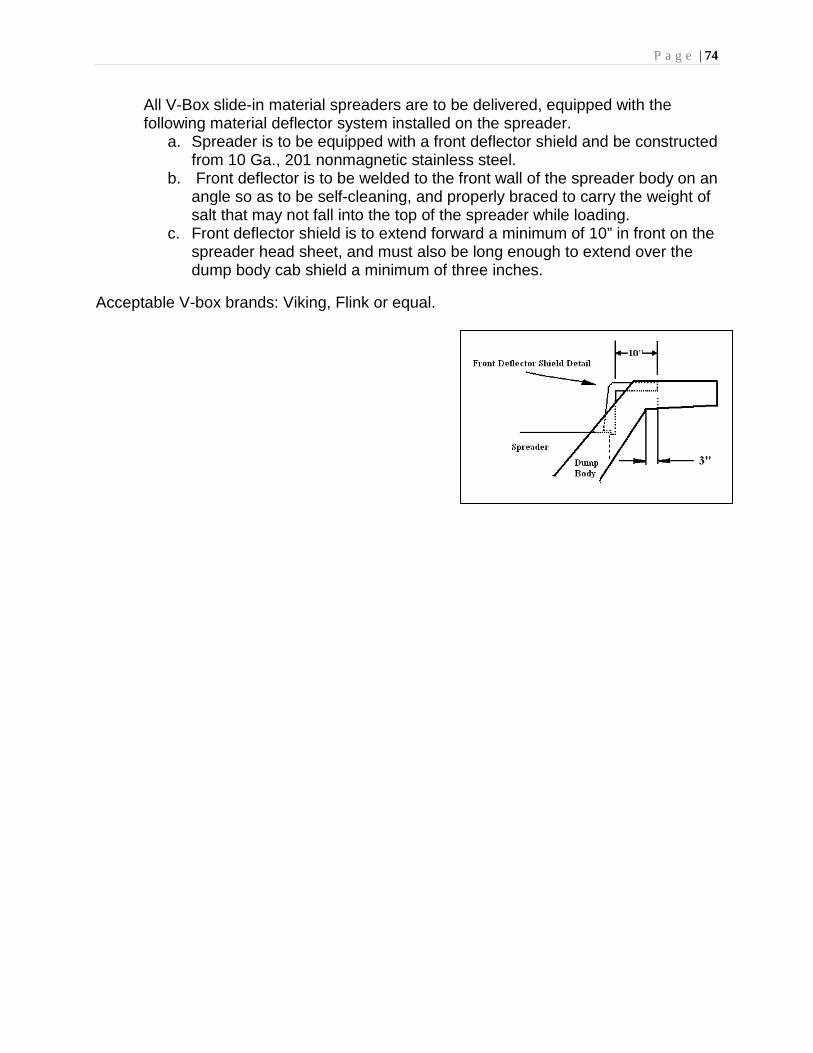
P a g e | 74
All V-Box slide-in material spreaders are to be delivered, equipped with the following material deflector system installed on the spreader.
a. Spreader is to be equipped with a front deflector shield and be constructed from 10 Ga., 201 nonmagnetic stainless steel.
b. Front deflector is to be welded to the front wall of the spreader body on an angle so as to be self-cleaning, and properly braced to carry the weight of salt that may not fall into the top of the spreader while loading.
c. Front deflector shield is to extend forward a minimum of 10” in front on the spreader head sheet, and must also be long enough to extend over the dump body cab shield a minimum of three inches.
Acceptable V-box brands: Viking, Flink or equal.