Embed Size (px)
Citation preview
Deploying Virtual Port Channel in NX-OSBRKDCT-2048
Gerard Chami
Customer Support Engineer
© 2014 Cisco and/or its affiliates. All rights reserved.BRKDCT-2048 Cisco Public
Session Abstract
This session is targeted to Network Engineers, Network Architects and IT administrators who have deployed or are considering the deployment of vPC to improve Layer 2 scalability and the network operational efficiency.
Session introduces basic concepts and terminology of the virtual Port-Channel technology & also covers actual designs and best practices of the vPCtechnology. Designs are targeted for aggregation/access layer and also for Data-Centre Interconnect.
VPC+ will be briefly covered in this session
Nexus 2000 (FEX) will only be addressed from vPC standpoint.
vPC troubleshooting will not be covered in this session
The presentation includes hidden and reference slides For YourReference
© 2014 Cisco and/or its affiliates. All rights reserved.BRKDCT-2048 Cisco Public
Agenda
Feature Overview
vPC Design Guidance and Best Practices
vPC Enhancements
Convergence
4
© 2014 Cisco and/or its affiliates. All rights reserved.BRKDCT-2048 Cisco Public
Agenda
Feature Overview
– vPC Concept & Benefits
– How does vPC help with STP?
– vPC Terminology
– Data-Plane Loop Avoidance with vPC
– vPC vs vPC+
vPC Design Guidance and Best Practices
vPC Enhancements
Convergence
5
VPC Feature Overview
6
© 2014 Cisco and/or its affiliates. All rights reserved.BRKDCT-2048 Cisco Public
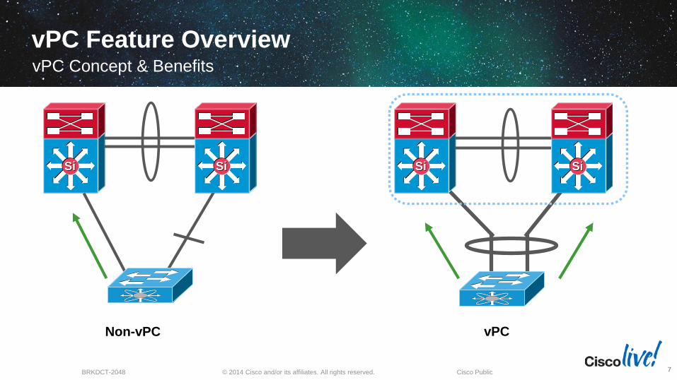
Non-vPC
SiSi SiSi
vPC
SiSi SiSi
vPC Feature OverviewvPC Concept & Benefits
7
© 2014 Cisco and/or its affiliates. All rights reserved.BRKDCT-2048 Cisco Public
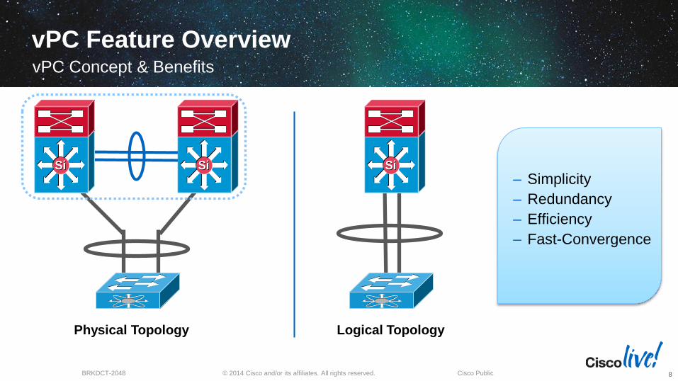
vPC Feature Overview
– Simplicity
– Redundancy
– Efficiency
– Fast-Convergence
vPC Concept & Benefits
8
Logical TopologyPhysical Topology
SiSi SiSi SiSi
© 2014 Cisco and/or its affiliates. All rights reserved.BRKDCT-2048 Cisco Public
Feature Overview
9
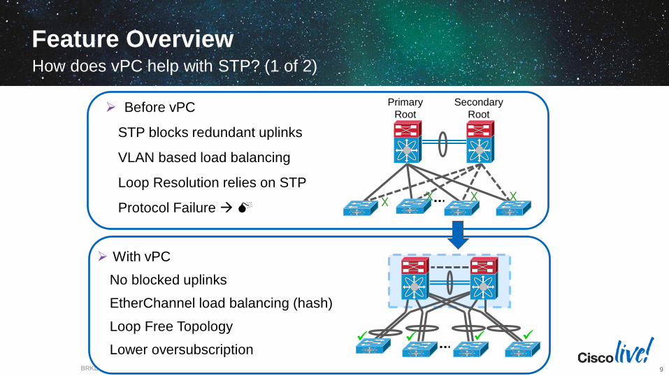
Before vPC
STP blocks redundant uplinks
VLAN based load balancing
Loop Resolution relies on STP
Protocol Failure
Primary
Root
Secondary
Root
With vPC
No blocked uplinks
EtherChannel load balancing (hash)
Loop Free Topology
Lower oversubscription
How does vPC help with STP? (1 of 2)
© 2014 Cisco and/or its affiliates. All rights reserved.BRKDCT-2048 Cisco Public
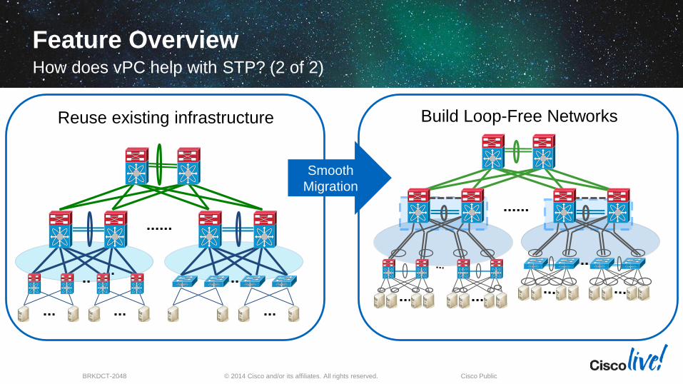
Feature OverviewHow does vPC help with STP? (2 of 2)
10
Reuse existing infrastructure Build Loop-Free Networks
Smooth
Migration
© 2014 Cisco and/or its affiliates. All rights reserved.BRKDCT-2048 Cisco Public
Feature Overview
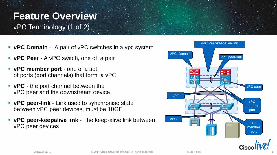
vPC Domain - A pair of vPC switches in a vpc system
vPC Peer - A vPC switch, one of a pair
vPC member port - one of a set of ports (port channels) that form a vPC
vPC - the port channel between the vPC peer and the downstream device
vPC peer-link - Link used to synchronise state between vPC peer devices, must be 10GE
vPC peer-keepalive link - The keep-alive link between vPC peer devices
vPC Terminology (1 of 2)
11
vPC
member
port
vPC
vPC
member
port
vPC peer-link
vPC peer
vPC Domain
vPC
vPC
member
port
vPC Peer-keepalive link
© 2014 Cisco and/or its affiliates. All rights reserved.BRKDCT-2048 Cisco Public
Feature OverviewvPC Terminology (2 of 2)
12
CFS protocol
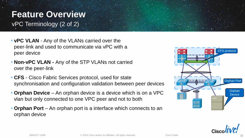
vPC VLAN - Any of the VLANs carried over the
peer-link and used to communicate via vPC with a
peer device
Non-vPC VLAN - Any of the STP VLANs not carried
over the peer-link
CFS - Cisco Fabric Services protocol, used for state
synchronisation and configuration validation between peer devices
Orphan Device – An orphan device is a device which is on a VPC
vlan but only connected to one VPC peer and not to both
Orphan Port – An orphan port is a interface which connects to an
orphan device
Orphan Port
Orphan
Device
© 2014 Cisco and/or its affiliates. All rights reserved.BRKDCT-2048 Cisco Public
Feature OverviewData-Plane Loop Avoidance with vPC (1 of 2)
13
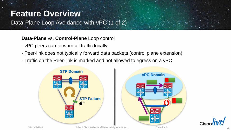
vPC DomainSTP Domain
STP Failure
Data-Plane vs. Control-Plane Loop control
- vPC peers can forward all traffic locally
- Peer-link does not typically forward data packets (control plane extension)
- Traffic on the Peer-link is marked and not allowed to egress on a vPC
© 2014 Cisco and/or its affiliates. All rights reserved.BRKDCT-2048 Cisco Public
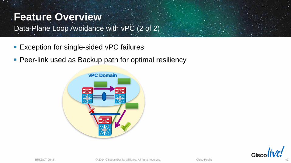
Feature Overview
Exception for single-sided vPC failures
Peer-link used as Backup path for optimal resiliency
Data-Plane Loop Avoidance with vPC (2 of 2)
14
vPC Domain
© 2014 Cisco and/or its affiliates. All rights reserved.BRKDCT-2048 Cisco Public
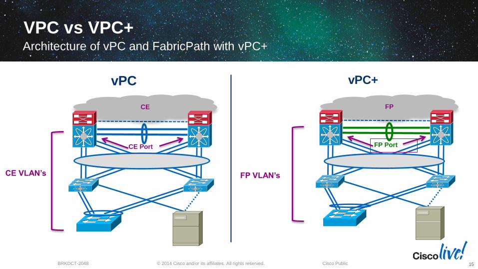
VPC vs VPC+Architecture of vPC and FabricPath with vPC+
15
vPC+
FP Port
FP VLAN’s
FP
CE VLAN’s
vPC
CE Port
CE
© 2014 Cisco and/or its affiliates. All rights reserved.BRKDCT-2048 Cisco Public
A
S10 S20 S30 S40
S100 S200S300
B
1/1
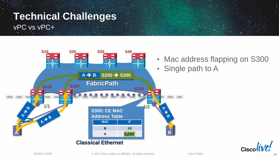
Technical Challenges
Classical Ethernet
1/2
FabricPath
S300: CE MAC
Address TableMAC IF
B 1/2
A S100
S100 S300A B
S100
S200 S300A B
S200
• Mac address flapping on S300
• Single path to A
16
vPC vs vPC+
© 2014 Cisco and/or its affiliates. All rights reserved.BRKDCT-2048 Cisco Public
A
S10 S20 S30 S40
S100 S200 S300
B
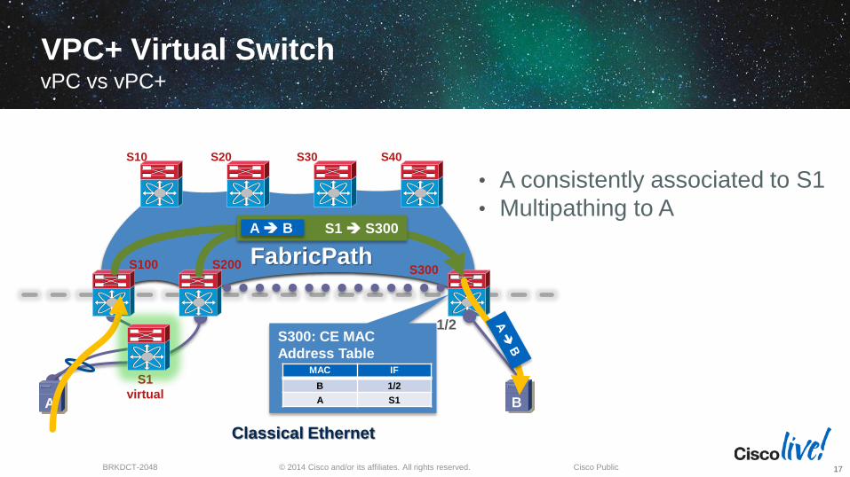
VPC+ Virtual Switch
Classical Ethernet
1/2
FabricPath
S300: CE MAC
Address TableMAC IF
B 1/2
A S1
S1
virtual
S1 S300A B
• A consistently associated to S1
• Multipathing to A
17
vPC vs vPC+
VPC Design Guidance & Best Practices
18
VPC Benefits :
High-availability, Redundancy, Low convergence & Full use of available bandwidth
© 2014 Cisco and/or its affiliates. All rights reserved.BRKDCT-2048 Cisco Public
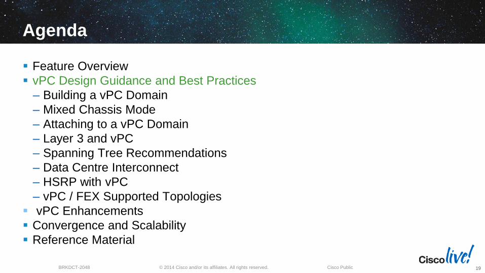
Agenda
Feature Overview
vPC Design Guidance and Best Practices
– Building a vPC Domain
– Mixed Chassis Mode
– Attaching to a vPC Domain
– Layer 3 and vPC
– Spanning Tree Recommendations
– Data Centre Interconnect
– HSRP with vPC
– vPC / FEX Supported Topologies
vPC Enhancements
Convergence and Scalability
Reference Material
19
© 2014 Cisco and/or its affiliates. All rights reserved.BRKDCT-2048 Cisco Public
Building a vPC DomainConfiguration Steps
20
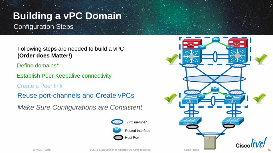
Following steps are needed to build a vPC
(Order does Matter!)
vPC member
Routed Interface
Host Port
Define domains*
Establish Peer Keepalive connectivity
Create a Peer link
Reuse port-channels and Create vPCs
Make Sure Configurations are Consistent
© 2014 Cisco and/or its affiliates. All rights reserved.BRKDCT-2048 Cisco Public
Building a vPC DomainvPC Domains
21
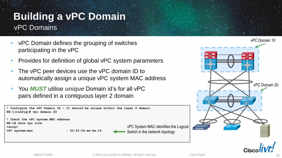
! Configure the vPC Domain ID – It should be unique within the layer 2 domain
NX-1(config)# vpc domain 20
! Check the vPC system MAC address
NX-1# show vpc role
<snip>
vPC system-mac : 00:23:04:ee:be:14
vPC Domain 20
vPC System MAC identifies the Logical
Switch in the network topology
vPC Domain 10 vPC Domain defines the grouping of switches
participating in the vPC
Provides for definition of global vPC system parameters
The vPC peer devices use the vPC domain ID to
automatically assign a unique vPC system MAC address
You MUST utilise unique Domain id’s for all vPC
pairs defined in a contiguous layer 2 domain
© 2014 Cisco and/or its affiliates. All rights reserved.BRKDCT-2048 Cisco Public
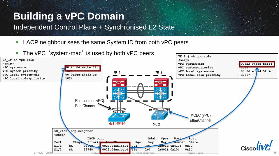
5K_2#sh lacp neighbor
<snip>
LACP port Admin Oper Port Port
Port Flags Priority Dev ID Age key Key Number State
E1/1 SA 32768 0023.04ee.be14 9s 0x0 0x801E 0x4104 0x3D
E1/2 SA 32768 0023.04ee.be14 21s 0x0 0x801E 0x104 0x3D
7K_2 # sh vpc role
<snip>
vPC system-mac : 00:23:04:ee:be:14
vPC system-priority : 1024
vPC local system-mac : 00:0d:ec:a4:5f:7c
vPC local role-priority : 32667
7K_1# sh vpc role
<snip>
vPC system-mac : 00:23:04:ee:be:14
vPC system-priority : 1024
vPC local system-mac : 00:0d:ec:a4:53:3c
vPC local role-priority : 1024
dc11-4948-1
LACP neighbour sees the same System ID from both vPC peers
The vPC ‘system-mac’ is used by both vPC peers
5K_2
7K_1 7K_2
1/4 1/5
Regular (non vPC)
Port Channel1/1 1/2
MCEC (vPC)
EtherChannel
Building a vPC DomainIndependent Control Plane + Synchronised L2 State
22
© 2014 Cisco and/or its affiliates. All rights reserved.BRKDCT-2048 Cisco Public
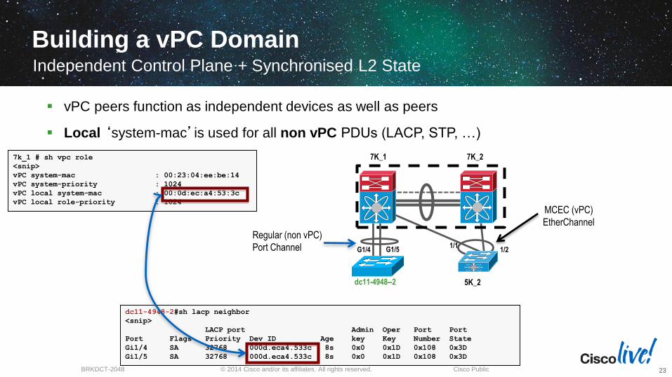
dc11-4948-2#sh lacp neighbor
<snip>
LACP port Admin Oper Port Port
Port Flags Priority Dev ID Age key Key Number State
Gi1/4 SA 32768 000d.eca4.533c 8s 0x0 0x1D 0x108 0x3D
Gi1/5 SA 32768 000d.eca4.533c 8s 0x0 0x1D 0x108 0x3D
7k_1 # sh vpc role
<snip>
vPC system-mac : 00:23:04:ee:be:14
vPC system-priority : 1024
vPC local system-mac : 00:0d:ec:a4:53:3c
vPC local role-priority : 1024
vPC peers function as independent devices as well as peers
Local ‘system-mac’is used for all non vPC PDUs (LACP, STP, …)
MCEC (vPC)
EtherChannel
5K_2
7K_1 7K_2
G1/4 G1/5
Regular (non vPC)
Port Channel 1/11/2
dc11-4948--2
Building a vPC DomainIndependent Control Plane + Synchronised L2 State
23
© 2014 Cisco and/or its affiliates. All rights reserved.BRKDCT-2048 Cisco Public
vPC Domain 20
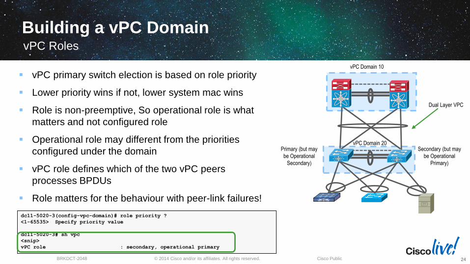
dc11-5020-3(config-vpc-domain)# role priority ?
<1-65535> Specify priority value
dc11-5020-3# sh vpc
<snip>
vPC role : secondary, operational primary
Secondary (but may
be Operational
Primary)
Primary (but may
be Operational
Secondary)
vPC Domain 10
Dual Layer VPC
vPC primary switch election is based on role priority
Lower priority wins if not, lower system mac wins
Role is non-preemptive, So operational role is what
matters and not configured role
Operational role may different from the priorities
configured under the domain
vPC role defines which of the two vPC peers
processes BPDUs
Role matters for the behaviour with peer-link failures!
vPC Roles
24
Building a vPC Domain
© 2014 Cisco and/or its affiliates. All rights reserved.BRKDCT-2048 Cisco Public
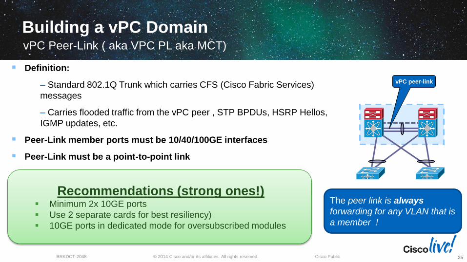
Recommendations (strong ones!) Minimum 2x 10GE ports
Use 2 separate cards for best resiliency)
10GE ports in dedicated mode for oversubscribed modules
Building a vPC DomainvPC Peer-Link ( aka VPC PL aka MCT)
25
vPC peer-link
Definition:
‒ Standard 802.1Q Trunk which carries CFS (Cisco Fabric Services)
messages
‒ Carries flooded traffic from the vPC peer , STP BPDUs, HSRP Hellos,
IGMP updates, etc.
Peer-Link member ports must be 10/40/100GE interfaces
Peer-Link must be a point-to-point link
The peer link is always
forwarding for any VLAN that is
a member !
© 2014 Cisco and/or its affiliates. All rights reserved.BRKDCT-2048 Cisco Public
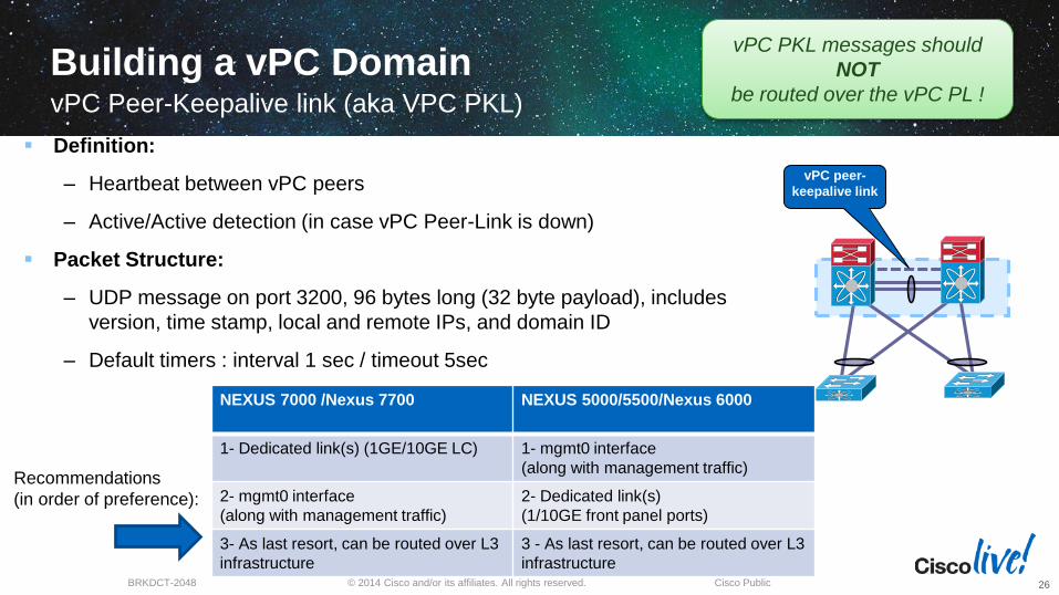
Building a vPC DomainvPC Peer-Keepalive link (aka VPC PKL)
26
vPC peer-
keepalive link
NEXUS 7000 /Nexus 7700 NEXUS 5000/5500/Nexus 6000
1- Dedicated link(s) (1GE/10GE LC) 1- mgmt0 interface
(along with management traffic)
2- mgmt0 interface
(along with management traffic)
2- Dedicated link(s)
(1/10GE front panel ports)
3- As last resort, can be routed over L3
infrastructure
3 - As last resort, can be routed over L3
infrastructure
Recommendations
(in order of preference):
Definition:
‒ Heartbeat between vPC peers
‒ Active/Active detection (in case vPC Peer-Link is down)
Packet Structure:
‒ UDP message on port 3200, 96 bytes long (32 byte payload), includes
version, time stamp, local and remote IPs, and domain ID
‒ Default timers : interval 1 sec / timeout 5sec
vPC PKL messages should
NOT
be routed over the vPC PL !
© 2014 Cisco and/or its affiliates. All rights reserved.BRKDCT-2048 Cisco Public
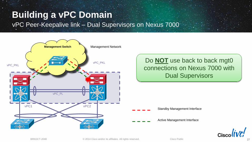
Building a vPC DomainvPC Peer-Keepalive link – Dual Supervisors on Nexus 7000
27
vPC1 vPC2
vPC_PL
Management Network
Standby Management Interface
Active Management Interface
Management Switch
vPC_PKLvPC_PKL
Do NOT use back to back mgt0
connections on Nexus 7000 with
Dual Supervisors
© 2014 Cisco and/or its affiliates. All rights reserved.BRKDCT-2048 Cisco Public
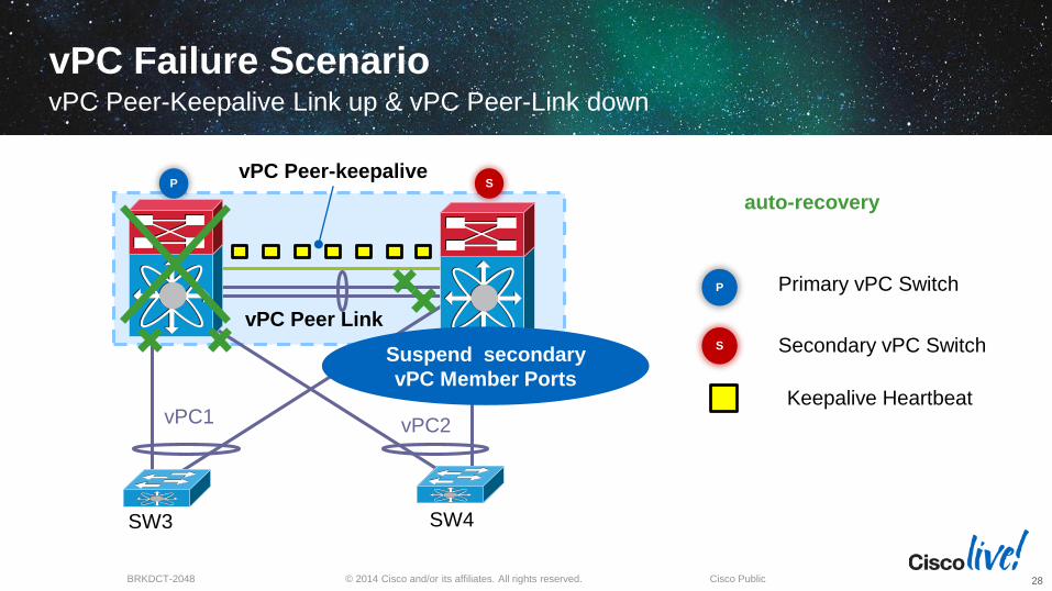
vPC Failure Scenario vPC Peer-Keepalive Link up & vPC Peer-Link down
28
Keepalive Heartbeat
Secondary vPC SwitchS
P Primary vPC Switch
SW3 SW4
vPC1 vPC2
vPC Peer Link
vPC Peer-keepalive P S
Suspend secondary
vPC Member Ports
auto-recovery
© 2014 Cisco and/or its affiliates. All rights reserved.BRKDCT-2048 Cisco Public
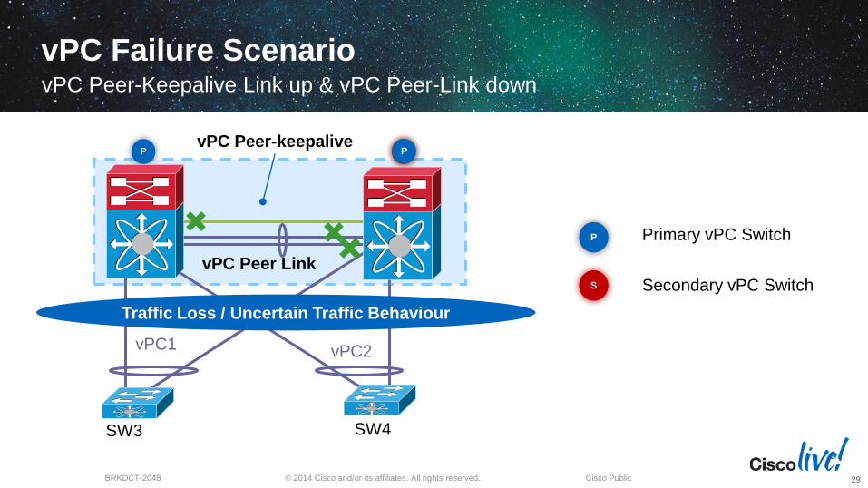
vPC Failure Scenario vPC Peer-Keepalive Link up & vPC Peer-Link down
29
Secondary vPC SwitchS
P Primary vPC Switch
SW3 SW4
vPC1 vPC2
vPC Peer Link
vPC Peer-keepalive P SP
Traffic Loss / Uncertain Traffic Behaviour
© 2014 Cisco and/or its affiliates. All rights reserved.BRKDCT-2048 Cisco Public
vPC Configuration ConsistencyvPC Control Plane - Consistency Check
30
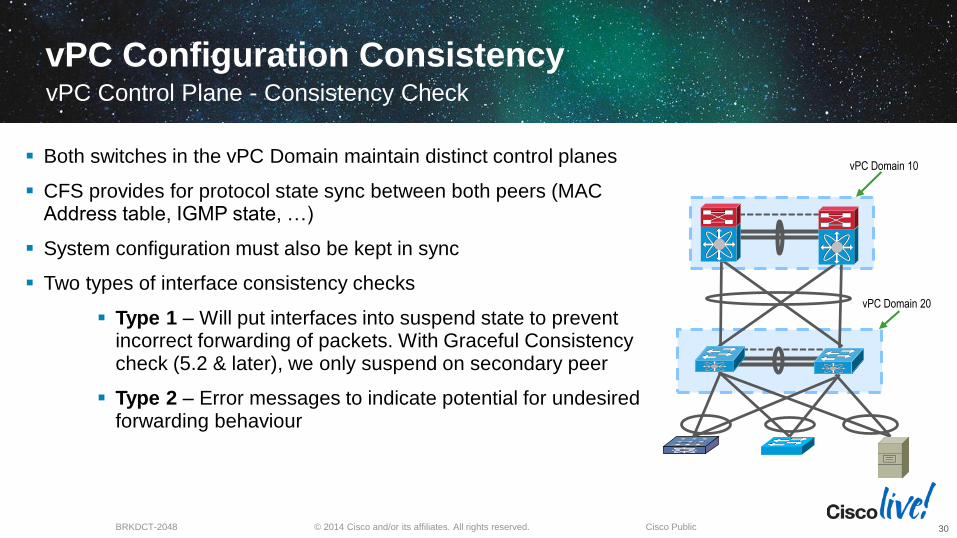
Both switches in the vPC Domain maintain distinct control planes
CFS provides for protocol state sync between both peers (MAC Address table, IGMP state, …)
System configuration must also be kept in sync
Two types of interface consistency checks
Type 1 – Will put interfaces into suspend state to prevent incorrect forwarding of packets. With Graceful Consistency check (5.2 & later), we only suspend on secondary peer
Type 2 – Error messages to indicate potential for undesired forwarding behaviour
vPC Domain 20
vPC Domain 10
© 2014 Cisco and/or its affiliates. All rights reserved.BRKDCT-2048 Cisco Public
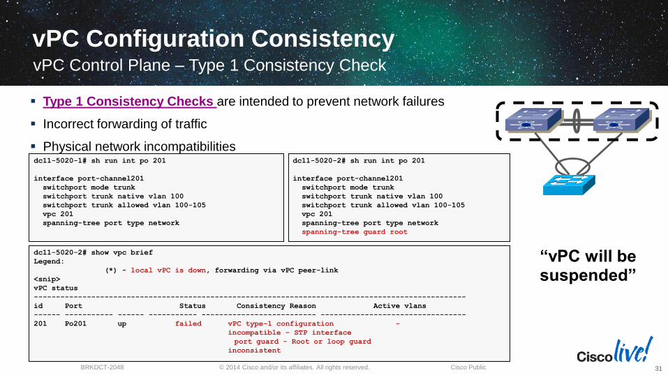
Type 1 Consistency Checks are intended to prevent network failures
Incorrect forwarding of traffic
Physical network incompatibilities
dc11-5020-2# show vpc brief
Legend:
(*) - local vPC is down, forwarding via vPC peer-link
<snip>
vPC status
--------------------------------------------------------------------------------------------------
id Port Status Consistency Reason Active vlans
------ ----------- ------ ----------- -------------------------- ---------------------------------
201 Po201 up failed vPC type-1 configuration -
incompatible – STP interface
port guard - Root or loop guard
inconsistent
dc11-5020-1# sh run int po 201
interface port-channel201
switchport mode trunk
switchport trunk native vlan 100
switchport trunk allowed vlan 100-105
vpc 201
spanning-tree port type network
dc11-5020-2# sh run int po 201
interface port-channel201
switchport mode trunk
switchport trunk native vlan 100
switchport trunk allowed vlan 100-105
vpc 201
spanning-tree port type network
spanning-tree guard root
“vPC will be suspended”
vPC Configuration ConsistencyvPC Control Plane – Type 1 Consistency Check
31
© 2014 Cisco and/or its affiliates. All rights reserved.BRKDCT-2048 Cisco Public
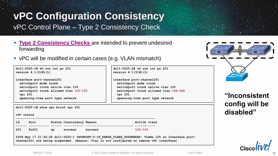
Type 2 Consistency Checks are intended to prevent undesired forwarding
vPC will be modified in certain cases (e.g. VLAN mismatch)
dc11-5020-1# show vpc brief vpc 201
vPC status
----------------------------------------------------------------------------
id Port Status Consistency Reason Active vlans
------ ----------- ------ ----------- -------------------------- -----------
201 Po201 up success success 100-104
2009 May 17 21:56:28 dc11-5020-1 %ETHPORT-5-IF_ERROR_VLANS_SUSPENDED: VLANs 105 on Interface port-
channel201 are being suspended. (Reason: Vlan is not configured on remote vPC interface)
dc11-5020-1# sh run int po 201
version 4.1(3)N1(1)
interface port-channel201
switchport mode trunk
switchport trunk native vlan 100
switchport trunk allowed vlan 100-105
vpc 201
spanning-tree port type network
dc11-5020-2# sh run int po 201
version 4.1(3)N1(1)
interface port-channel201
switchport mode trunk
switchport trunk native vlan 100
switchport trunk allowed vlan 100-104
vpc 201
spanning-tree port type network “Inconsistent
config will be
disabled”
vPC Configuration Consistency
32
vPC Control Plane – Type 2 Consistency Check
© 2014 Cisco and/or its affiliates. All rights reserved.BRKDCT-2048 Cisco Public
Virtual Port Channel (vPC)vPC Member Port
33
vPC
member
port
vPC
member
port
NX7K-2 :
interface port-channel201
switchport mode trunk
switchport trunk native vlan 100
switchport trunk allowed vlan 100-
105
vpc 201
NX7K-1 :
interface port-channel201
switchport mode trunk
switchport trunk native vlan 100
switchport trunk allowed vlan 100-
105
vpc 201
NX7K-1 NX7K-2
vPC 201
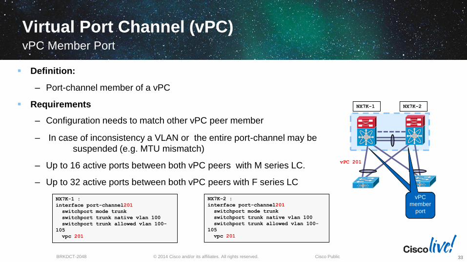
Definition:
‒ Port-channel member of a vPC
Requirements
‒ Configuration needs to match other vPC peer member
‒ In case of inconsistency a VLAN or the entire port-channel may be
suspended (e.g. MTU mismatch)
‒ Up to 16 active ports between both vPC peers with M series LC.
‒ Up to 32 active ports between both vPC peers with F series LC
© 2014 Cisco and/or its affiliates. All rights reserved.BRKDCT-2048 Cisco Public
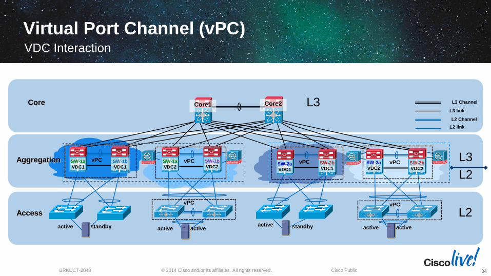
Virtual Port Channel (vPC)VDC Interaction
34
Access
L2
L3
L3
L2
L2 Channel
L3 link
L2 link
L3 ChannelCore
Aggregation SW-2b
VDC2
SW-2a
VDC2SW-2a
VDC1
SW-2b
VDC1
SW-1a
VDC2
SW-1b
VDC2SW-1a
VDC1
SW-1b
VDC1
Core2Core1
vPC vPC
active activeactive standbyactive activeactive standby
vPCvPC vPCvPC
© 2014 Cisco and/or its affiliates. All rights reserved.BRKDCT-2048 Cisco Public
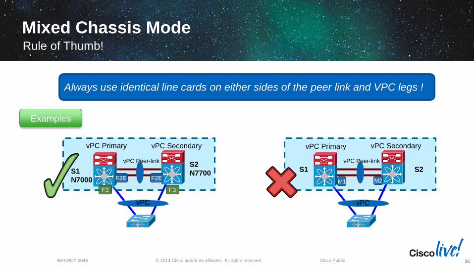
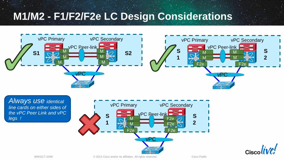
Mixed Chassis ModeRule of Thumb!
35
Always use identical line cards on either sides of the peer link and VPC legs !
vPC Peer-link
S1 S2
vPC Primary vPC Secondary
M2M1
vPC
vPC Peer-link
S1
N7000
S2
N7700
vPC Primary vPC Secondary
F3
vPC
F3
F2E F2E
Examples
© 2014 Cisco and/or its affiliates. All rights reserved.BRKDCT-2048 Cisco Public
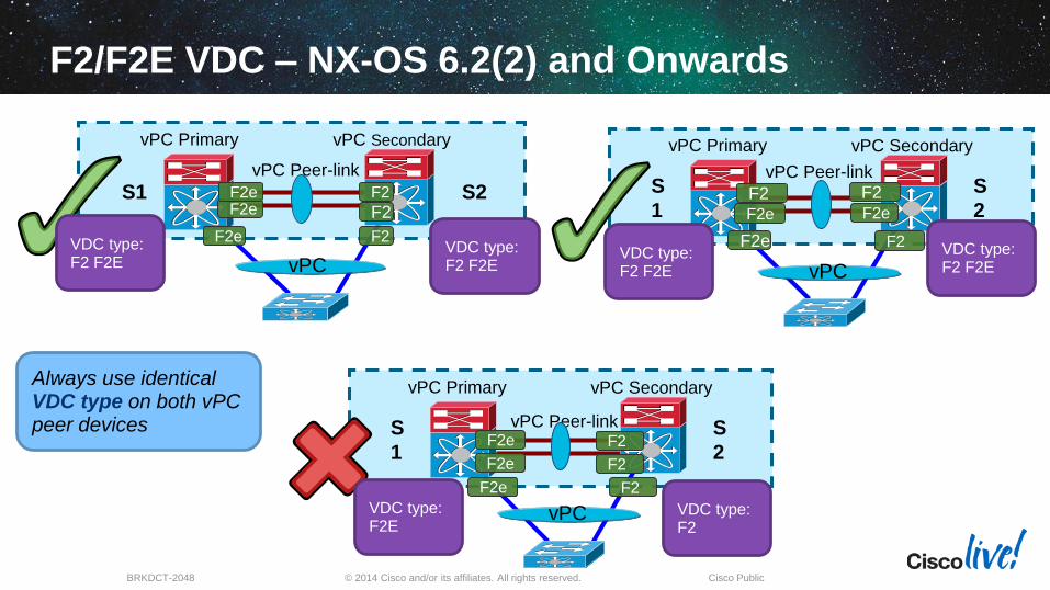
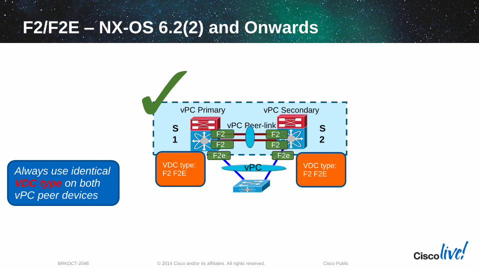
F2/F2E VDC – NX-OS 6.2(2) and Onwards
vPC Peer-link
S1 S2
vPC Primary vPC Secondary
F2e
vPC
vPC Peer-linkS
1
S
2
vPC Primary vPC Secondary
F2e F2e
vPC
vPC Peer-linkS
1
S
2
vPC Primary vPC Secondary
F2e F2
vPC
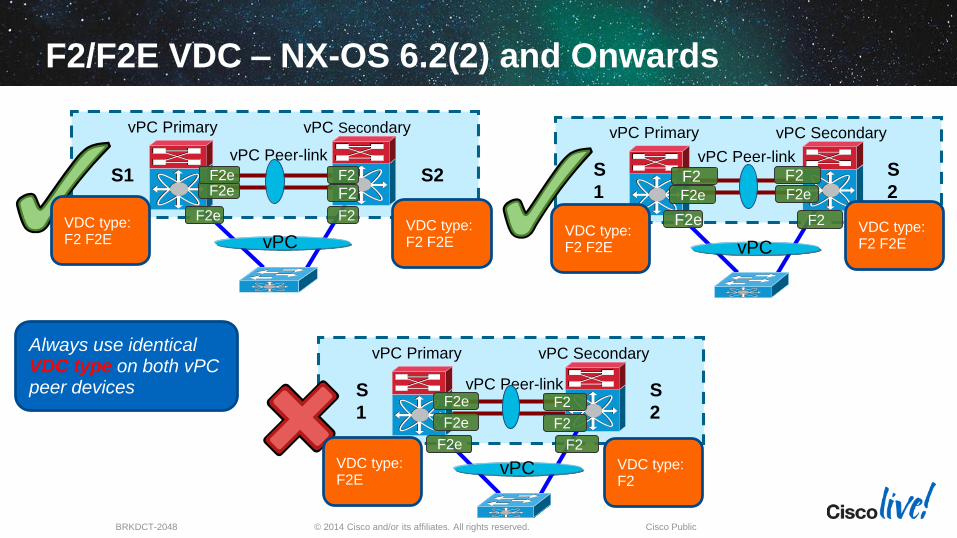
Always use identical VDC type on both vPCpeer devices
F2e F2 F2 F2F2
F2e F2 F2e F2VDC type: F2 F2E
VDC type: F2 F2E
VDC type: F2 F2E
VDC type: F2 F2E
F2e F2
F2e F2
VDC type: F2E
VDC type: F2
© 2014 Cisco and/or its affiliates. All rights reserved.BRKDCT-2048 Cisco Public
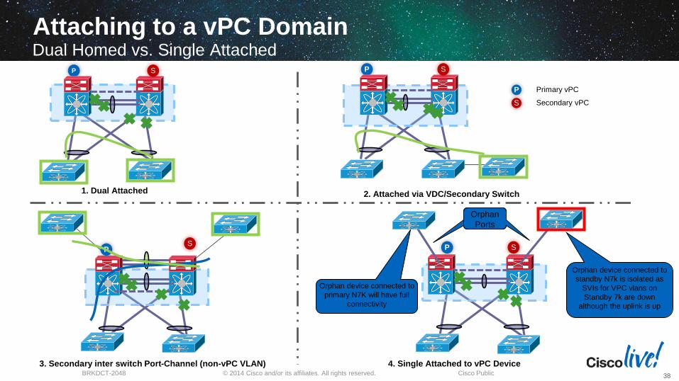
Attaching to a vPC DomainThe Most Important Rule…
37
Always Dual Attach Devices
to a vPC Domain!!!
© 2014 Cisco and/or its affiliates. All rights reserved.BRKDCT-2048 Cisco Public
Orphan
Ports
Orphan
Ports
SP
4. Single Attached to vPC Device
SP
2. Attached via VDC/Secondary Switch
SP
3. Secondary inter switch Port-Channel (non-vPC VLAN)
1. Dual Attached
Primary vPC
Secondary vPCS
P
Attaching to a vPC Domain
38
Dual Homed vs. Single AttachedSP
Orphan device connected to
standby N7k is isolated as
SVIs for VPC vlans on
Standby 7k are down
although the uplink is up
Orphan device connected to
primary N7K will have full
connectivity
© 2014 Cisco and/or its affiliates. All rights reserved.BRKDCT-2048 Cisco Public
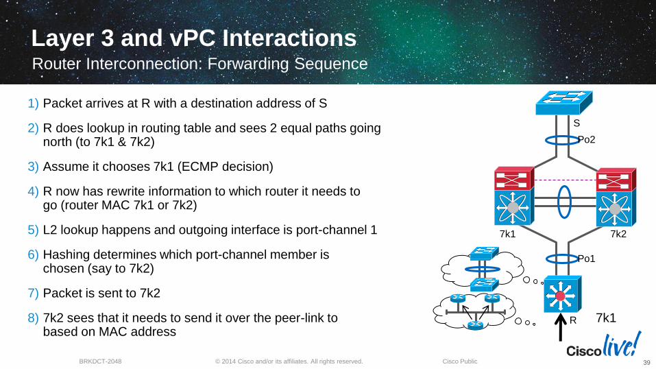
Layer 3 and vPC Interactions
1) Packet arrives at R with a destination address of S
2) R does lookup in routing table and sees 2 equal paths going north (to 7k1 & 7k2)
3) Assume it chooses 7k1 (ECMP decision)
4) R now has rewrite information to which router it needs to go (router MAC 7k1 or 7k2)
5) L2 lookup happens and outgoing interface is port-channel 1
6) Hashing determines which port-channel member is chosen (say to 7k2)
7) Packet is sent to 7k2
8) 7k2 sees that it needs to send it over the peer-link to 7k1 based on MAC address
Router Interconnection: Forwarding Sequence
39
R
7k2
S
Po1
Po2
7k1
© 2014 Cisco and/or its affiliates. All rights reserved.BRKDCT-2048 Cisco Public
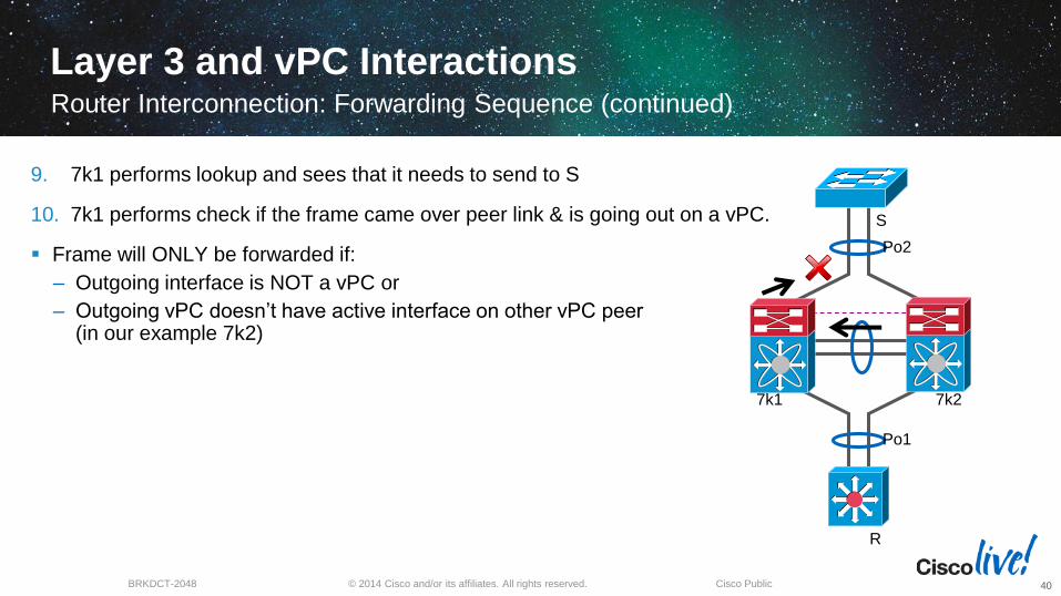
Layer 3 and vPC Interactions
9. 7k1 performs lookup and sees that it needs to send to S
10. 7k1 performs check if the frame came over peer link & is going out on a vPC.
Frame will ONLY be forwarded if:
– Outgoing interface is NOT a vPC or
– Outgoing vPC doesn’t have active interface on other vPC peer (in our example 7k2)
Router Interconnection: Forwarding Sequence (continued)
40
R
7k1 7k2
S
Po1
Po2
© 2014 Cisco and/or its affiliates. All rights reserved.BRKDCT-2048 Cisco Public
Router
7k1 7k2
Switch
Po1
Po2
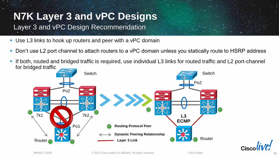
N7K Layer 3 and vPC Designs
Use L3 links to hook up routers and peer with a vPC domain
Don’t use L2 port channel to attach routers to a vPC domain unless you statically route to HSRP address
If both, routed and bridged traffic is required, use individual L3 links for routed traffic and L2 port-channel for bridged traffic
Layer 3 and vPC Design Recommendation
41
Router
Switch
L3 ECMP
Po2
PP
P
Routing Protocol Peer
Dynamic Peering Relationship
P
PP P
PP
Layer 3 Link
© 2014 Cisco and/or its affiliates. All rights reserved.BRKDCT-2048 Cisco Public
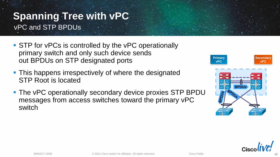
Spanning Tree with vPC
STP for vPCs is controlled by the vPC operationally primary switch and only such device sends out BPDUs on STP designated ports
This happens irrespectively of where the designated STP Root is located
The vPC operationally secondary device proxies STP BPDU messages from access switches toward the primary vPC switch
vPC and STP BPDUs
42
Primary
vPC
Secondary
vPC
BPDUs
© 2014 Cisco and/or its affiliates. All rights reserved.BRKDCT-2048 Cisco Public
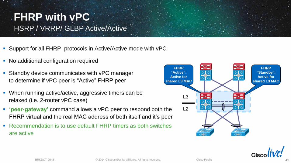
FHRP with vPCHSRP / VRRP/ GLBP Active/Active
43
Support for all FHRP protocols in Active/Active mode with vPC
No additional configuration required
Standby device communicates with vPC manager
to determine if vPC peer is “Active” FHRP peer
When running active/active, aggressive timers can be
relaxed (i.e. 2-router vPC case)
‘peer-gateway’ command allows a vPC peer to respond both the
FHRP virtual and the real MAC address of both itself and it’s peer
Recommendation is to use default FHRP timers as both switches
are active
L3
L2
FHRP
“Standby”:
Active for
shared L3 MAC
FHRP
“Active”:
Active for
shared L3 MAC
© 2014 Cisco and/or its affiliates. All rights reserved.BRKDCT-2048 Cisco Public
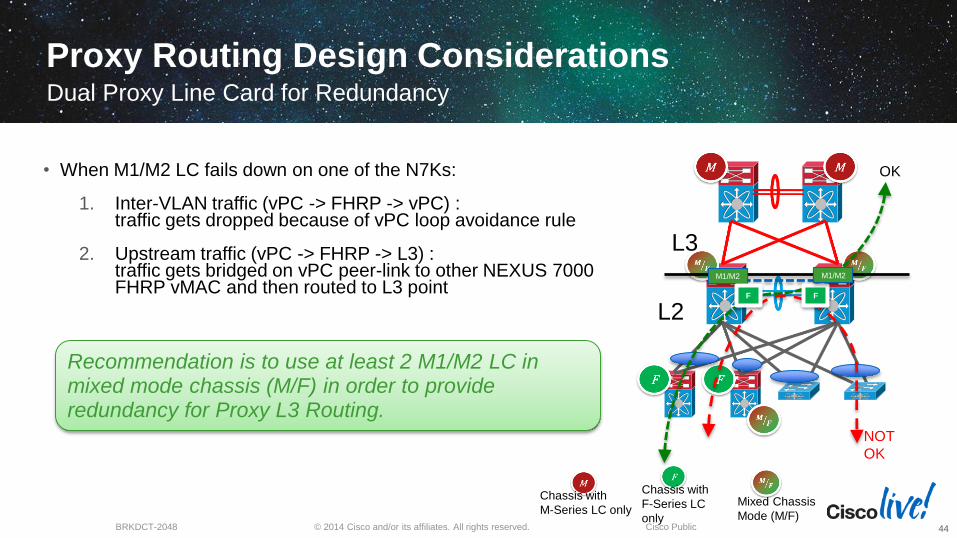
• When M1/M2 LC fails down on one of the N7Ks:
1. Inter-VLAN traffic (vPC -> FHRP -> vPC) : traffic gets dropped because of vPC loop avoidance rule
2. Upstream traffic (vPC -> FHRP -> L3) : traffic gets bridged on vPC peer-link to other NEXUS 7000 FHRP vMAC and then routed to L3 point
L3
L2
Chassis with
F-Series LC
only
Chassis with
M-Series LC only
M1/M2
OK
NOT
OK
F F
Proxy Routing Design ConsiderationsDual Proxy Line Card for Redundancy
44
Recommendation is to use at least 2 M1/M2 LC in mixed mode chassis (M/F) in order to provideredundancy for Proxy L3 Routing.
M1/M2
Mixed Chassis
Mode (M/F)
© 2014 Cisco and/or its affiliates. All rights reserved.BRKDCT-2048 Cisco Public
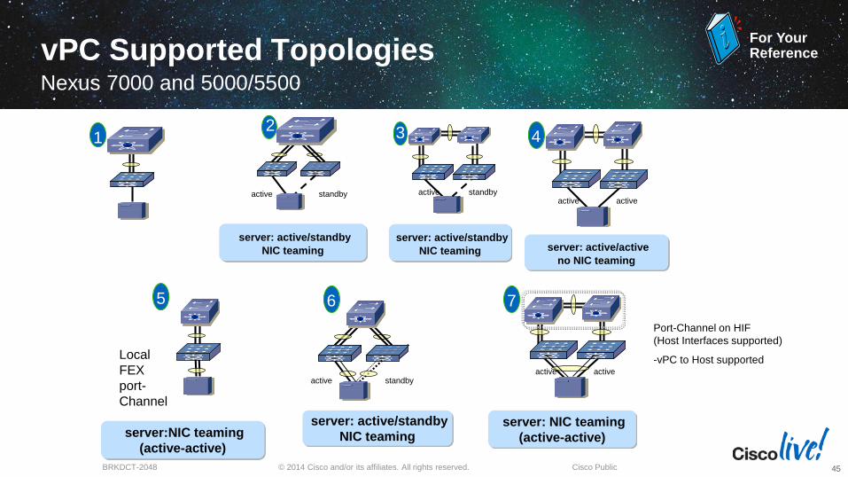
1
standbyactive
server: active/standby
NIC teaming
2
standbyactive
server: active/standby
NIC teaming
3
activeactive
server: active/active
no NIC teaming
4
Local
FEX
port-
Channel
server:NIC teaming
(active-active)
5
activeactive
server: NIC teaming
(active-active)
standbyactive
server: active/standby
NIC teaming
6 87
Port-Channel on HIF
(Host Interfaces supported)
-vPC to Host supported
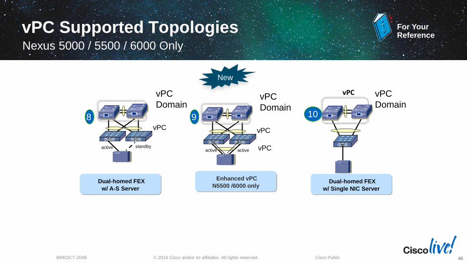
For YourReferencevPC Supported Topologies
Nexus 7000 and 5000/5500
45
© 2014 Cisco and/or its affiliates. All rights reserved.BRKDCT-2048 Cisco Public
standbyactive
vPC
vPC
Domain
activeactive
vPC
vPC
Domain
vPC
vPC vPC
Domain
8 9 10
New
For YourReference
vPC Supported TopologiesNexus 5000 / 5500 / 6000 Only
46
Dual-homed FEX
w/ A-S Server
Dual-homed FEX
w/ Single NIC Server
Enhanced vPC
N5500 /6000 only
© 2014 Cisco and/or its affiliates. All rights reserved.BRKDCT-2048 Cisco Public
active
7
active
11
activeactive
vPC
Domain
vPC
812
VDC1 VDC2
activeactivevPC
813
vPC
vPC
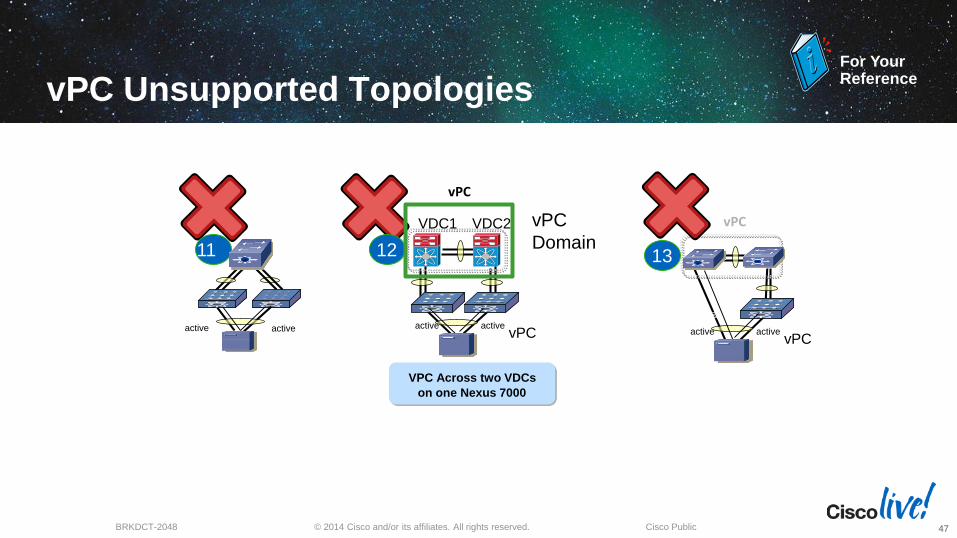
For YourReference
vPC Unsupported Topologies
47
VPC Across two VDCs
on one Nexus 7000
© 2014 Cisco and/or its affiliates. All rights reserved.BRKDCT-2048 Cisco Public
Agenda
Feature Overview
vPC Design Guidance and Best Practices
vPC Enhancements
Convergence
48
vPC Enhancements
49
© 2014 Cisco and/or its affiliates. All rights reserved.BRKDCT-2048 Cisco Public
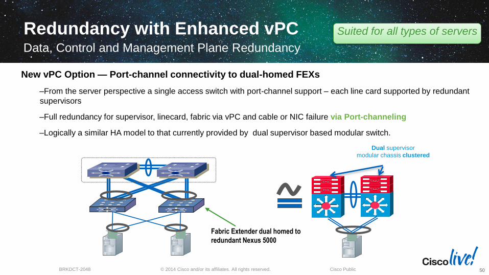
Redundancy with Enhanced vPC Data, Control and Management Plane Redundancy
50
Dual supervisor
modular chassis clustered
Fabric Extender dual homed to
redundant Nexus 5000
New vPC Option — Port-channel connectivity to dual-homed FEXs
‒From the server perspective a single access switch with port-channel support – each line card supported by redundant
supervisors
‒Full redundancy for supervisor, linecard, fabric via vPC and cable or NIC failure via Port-channeling
‒Logically a similar HA model to that currently provided by dual supervisor based modular switch.
Suited for all types of servers
© 2014 Cisco and/or its affiliates. All rights reserved.BRKDCT-2048 Cisco Public
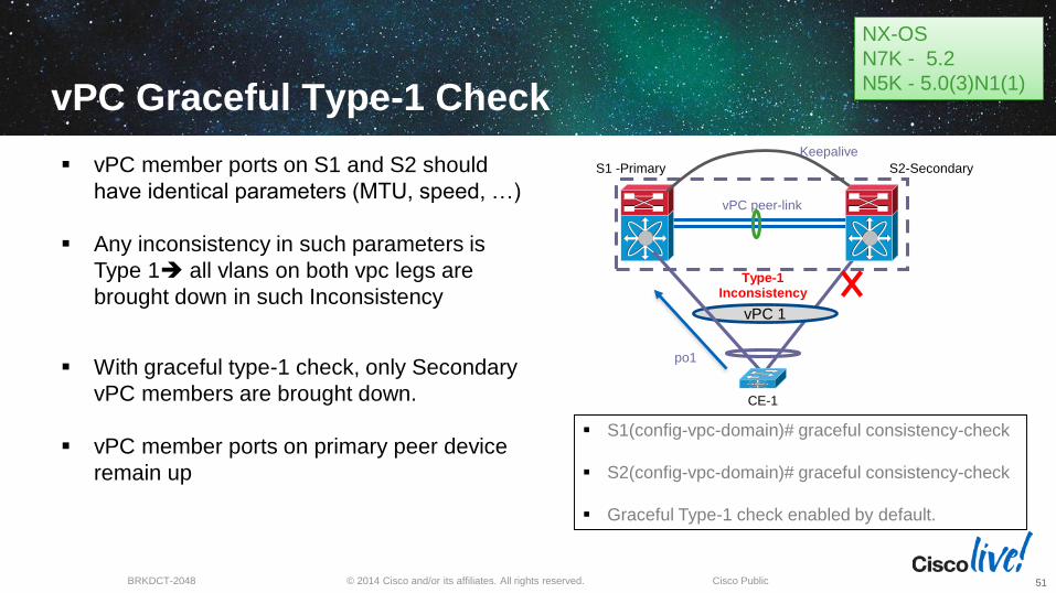
vPC Graceful Type-1 Check
51
CE-1
S2-SecondaryS1 -Primary
vPC peer-link
vPC 1
po1
Keepalive
vPC member ports on S1 and S2 should
have identical parameters (MTU, speed, …)
Any inconsistency in such parameters is
Type 1 all vlans on both vpc legs are
brought down in such Inconsistency
With graceful type-1 check, only Secondary
vPC members are brought down.
vPC member ports on primary peer device
remain up
S1(config-vpc-domain)# graceful consistency-check
S2(config-vpc-domain)# graceful consistency-check
Graceful Type-1 check enabled by default.
Type-1 Inconsistency
NX-OS
N7K - 5.2
N5K - 5.0(3)N1(1)
© 2014 Cisco and/or its affiliates. All rights reserved.BRKDCT-2048 Cisco Public
vPC Supported Server fails over
correctlyActive/Standby Server does not fail over correctly since orphan port is still active
vPC
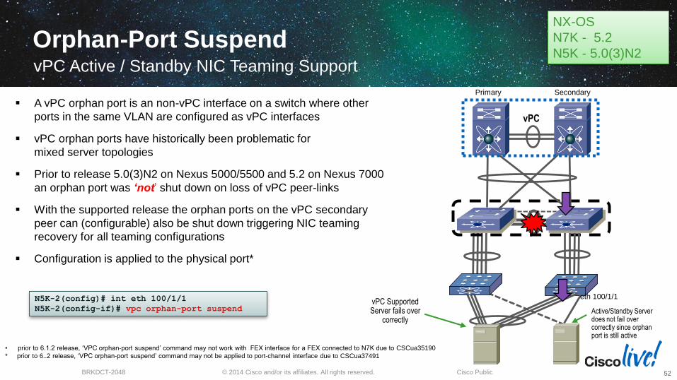
Orphan-Port SuspendvPC Active / Standby NIC Teaming Support
52
N5K-2(config)# int eth 100/1/1
N5K-2(config-if)# vpc orphan-port suspend
eth 100/1/1
A vPC orphan port is an non-vPC interface on a switch where other
ports in the same VLAN are configured as vPC interfaces
vPC orphan ports have historically been problematic for
mixed server topologies
Prior to release 5.0(3)N2 on Nexus 5000/5500 and 5.2 on Nexus 7000
an orphan port was ‘not’ shut down on loss of vPC peer-links
With the supported release the orphan ports on the vPC secondary
peer can (configurable) also be shut down triggering NIC teaming
recovery for all teaming configurations
Configuration is applied to the physical port*
• prior to 6.1.2 release, ‘VPC orphan-port suspend’ command may not work with FEX interface for a FEX connected to N7K due to CSCua35190
* prior to 6..2 release, ‘VPC orphan-port suspend’ command may not be applied to port-channel interface due to CSCua37491
Primary Secondary
NX-OS
N7K - 5.2
N5K - 5.0(3)N2
© 2014 Cisco and/or its affiliates. All rights reserved.BRKDCT-2048 Cisco Public
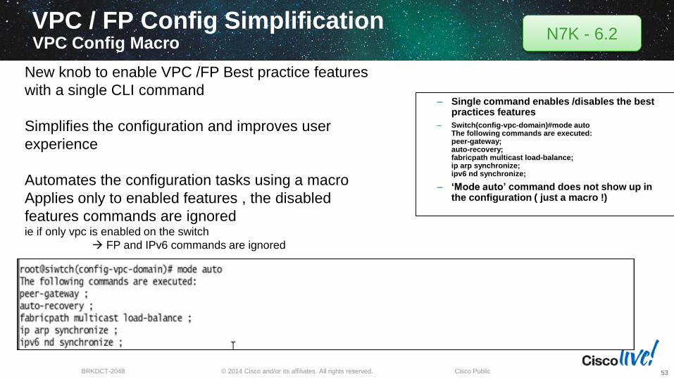
VPC / FP Config SimplificationVPC Config Macro
– Single command enables /disables the best practices features
– Switch(config-vpc-domain)#mode auto The following commands are executed: peer-gateway; auto-recovery; fabricpath multicast load-balance; ip arp synchronize; ipv6 nd synchronize;
– ‘Mode auto’ command does not show up in the configuration ( just a macro !)
New knob to enable VPC /FP Best practice features
with a single CLI command
Simplifies the configuration and improves user
experience
Automates the configuration tasks using a macro
Applies only to enabled features , the disabled
features commands are ignored ie if only vpc is enabled on the switch
FP and IPv6 commands are ignored
N7K - 6.2
53
Convergence
54

© 2014 Cisco and/or its affiliates. All rights reserved.BRKDCT-2048 Cisco Public
Agenda
Feature Overview
vPC Design Guidance and Best Practices
vPC Enhancements
Convergence
55
© 2014 Cisco and/or its affiliates. All rights reserved.BRKDCT-2048 Cisco Public
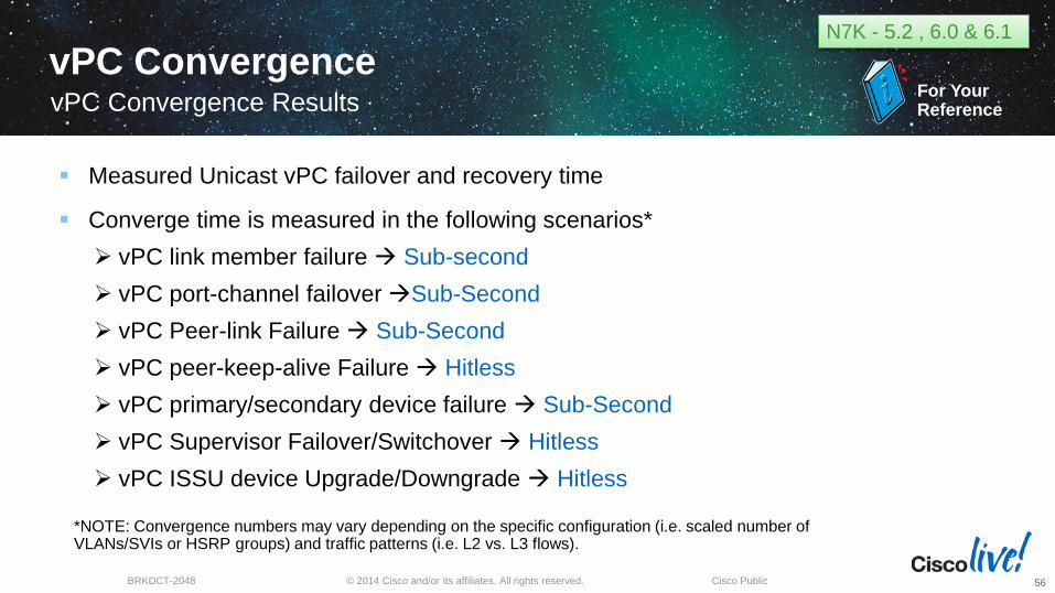
vPC ConvergencevPC Convergence Results
56
*NOTE: Convergence numbers may vary depending on the specific configuration (i.e. scaled number of VLANs/SVIs or HSRP groups) and traffic patterns (i.e. L2 vs. L3 flows).
Measured Unicast vPC failover and recovery time
Converge time is measured in the following scenarios*
vPC link member failure Sub-second
vPC port-channel failover Sub-Second
vPC Peer-link Failure Sub-Second
vPC peer-keep-alive Failure Hitless
vPC primary/secondary device failure Sub-Second
vPC Supervisor Failover/Switchover Hitless
vPC ISSU device Upgrade/Downgrade Hitless
N7K - 5.2 , 6.0 & 6.1
For YourReference
© 2014 Cisco and/or its affiliates. All rights reserved.BRKDCT-2048 Cisco Public
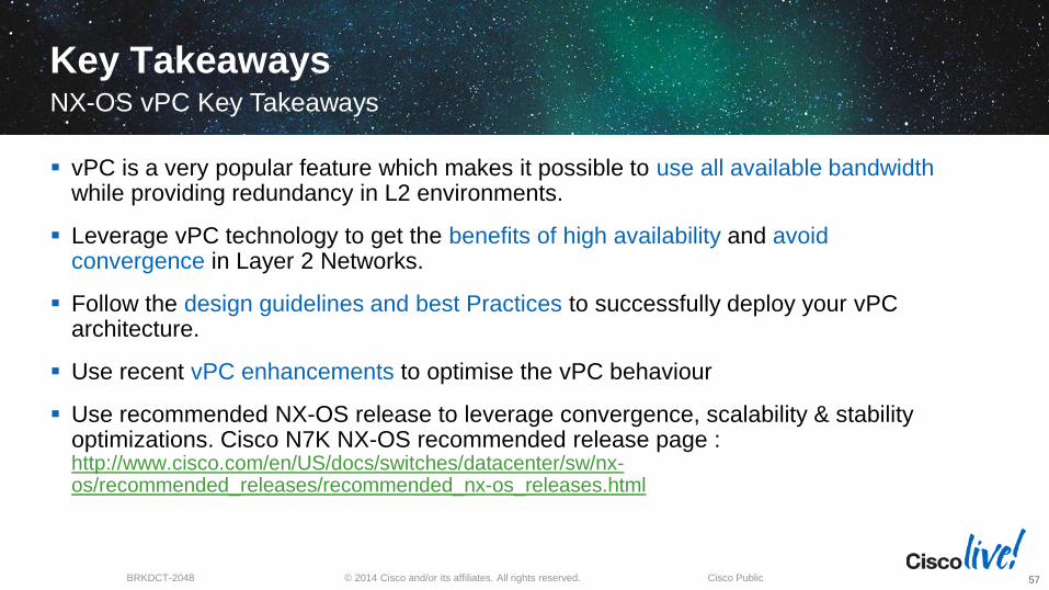
Key TakeawaysNX-OS vPC Key Takeaways
57
vPC is a very popular feature which makes it possible to use all available bandwidthwhile providing redundancy in L2 environments.
Leverage vPC technology to get the benefits of high availability and avoid convergence in Layer 2 Networks.
Follow the design guidelines and best Practices to successfully deploy your vPC architecture.
Use recent vPC enhancements to optimise the vPC behaviour
Use recommended NX-OS release to leverage convergence, scalability & stability optimizations. Cisco N7K NX-OS recommended release page : http://www.cisco.com/en/US/docs/switches/datacenter/sw/nx-os/recommended_releases/recommended_nx-os_releases.html
Q & A
© 2014 Cisco and/or its affiliates. All rights reserved.BRKDCT-2048 Cisco Public
Complete Your Online Session Evaluation
Give us your feedback and receive a Cisco Live 2014 Polo Shirt!
Complete your Overall Event Survey and 5 Session Evaluations.
Directly from your mobile device on the Cisco Live Mobile App
By visiting the Cisco Live Mobile Site www.ciscoliveaustralia.com/mobile
Visit any Cisco Live Internet Station located throughout the venue
Polo Shirts can be collected in the World of Solutions on Friday 21 March 12:00pm - 2:00pm
Learn online with Cisco Live!
Visit us online after the conference for full access
to session videos and presentations.
www.CiscoLiveAPAC.com

AppendixM1/M2 - F1/F2/F2e LC Design Considerations
© 2014 Cisco and/or its affiliates. All rights reserved.BRKDCT-2048 Cisco Public
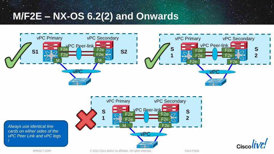
M/F2E – NX-OS 6.2(2) and Onwards
vPC Peer-link
S1 S2
vPC Primary vPC Secondary
M M
vPC
vPC Peer-linkS
1
S
2
vPC Primary vPC Secondary
F2e F2e
vPC
vPC Peer-linkS
1
S
2
vPC Primary vPC Secondary
F2e F2e
vPC
Always use identical line cards on either sides of the vPC Peer Link and vPC legs !
F2e F2e F2e F2eF2e F2e F2e F2e
F2e F2e
M F2e
© 2014 Cisco and/or its affiliates. All rights reserved.BRKDCT-2048 Cisco Public
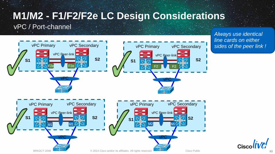
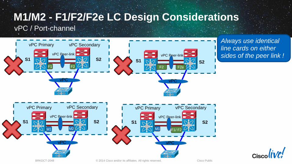
M1/M2 - F1/F2/F2e LC Design ConsiderationsvPC / Port-channel
63
vPC Peer-link
S1 S2
vPC Primary vPC Secondary
F2e F2e
vPC
vPC Peer-link
S1 S2
vPC Primary vPC Secondary
M2
vPC
vPC Peer-link
S1 S2
vPC Primary vPC Secondary
M1M1
vPC
vPC Peer-link
S1 S2
vPC Primary vPC Secondary
F2 F2
vPC
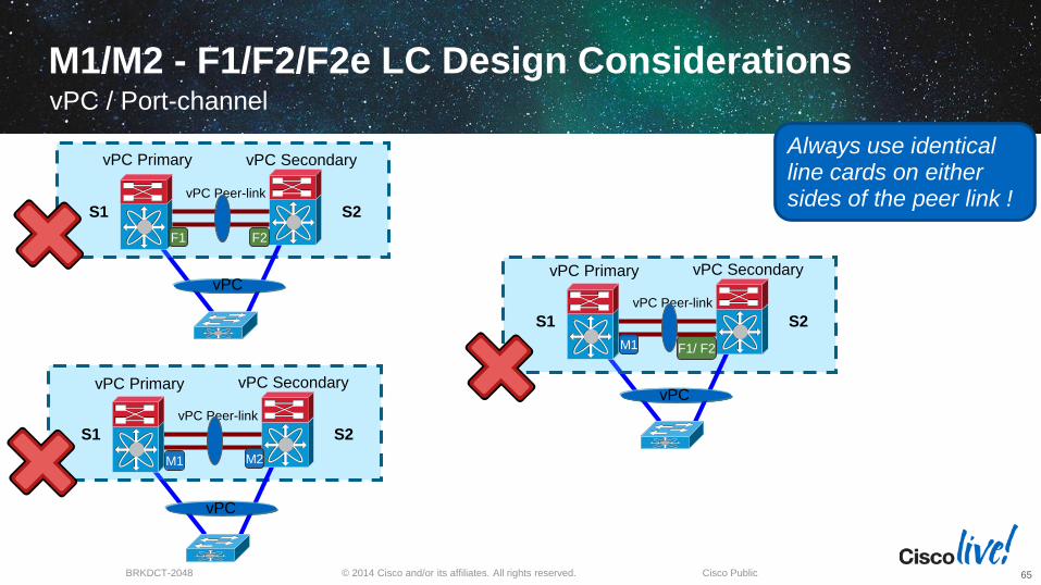
Always use identical line cards on either sides of the peer link !
M2
© 2014 Cisco and/or its affiliates. All rights reserved.BRKDCT-2048 Cisco Public
N7000 – N7700 VPC Design ConsiderationsvPC / Port-channel
vPC Peer-link
S1
N7000
S2
N7700
vPC Primary vPC Secondary
F3
vPC
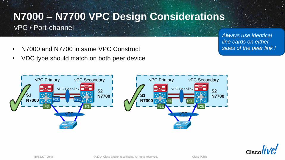
Always use identical line cards on either sides of the peer link !• N7000 and N7700 in same VPC Construct
• VDC type should match on both peer device
vPC Peer-link
S1
N7000
S2
N7700
vPC Primary vPC Secondary
F2E F2E
vPC
F2EF3
F2E
F2E
F2E
© 2014 Cisco and/or its affiliates. All rights reserved.BRKDCT-2048 Cisco Public
M1/M2 - F1/F2/F2e LC Design ConsiderationsvPC / Port-channel
65
vPC Peer-link
S1 S2
vPC Primary vPC Secondary
F1 F2
vPCvPC Peer-link
S1 S2
vPC Primary vPC Secondary
F1/ F2 M1
vPC
vPC Peer-link
S1 S2
vPC Primary vPC Secondary
M2M1
vPC
Always use identical line cards on either sides of the peer link !
© 2014 Cisco and/or its affiliates. All rights reserved.BRKDCT-2048 Cisco Public
F2/F2E VDC – NX-OS 6.2(2) and Onwards
vPC Peer-link
S1 S2
vPC Primary vPC Secondary
F2e
vPC
vPC Peer-linkS
1
S
2
vPC Primary vPC Secondary
F2e F2e
vPC
vPC Peer-linkS
1
S
2
vPC Primary vPC Secondary
F2e F2
vPC
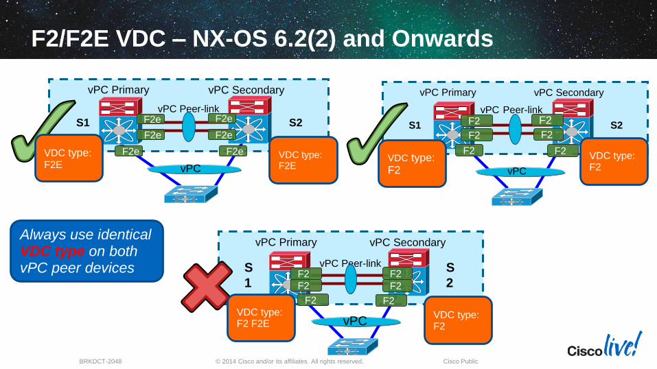
Always use identical VDC type on both vPCpeer devices
F2e F2 F2 F2F2
F2e F2 F2e F2VDC type: F2 F2E
VDC type: F2 F2E
VDC type: F2 F2E
VDC type: F2 F2E
F2e F2
F2e F2
VDC type: F2E
VDC type: F2
© 2014 Cisco and/or its affiliates. All rights reserved.BRKDCT-2048 Cisco Public
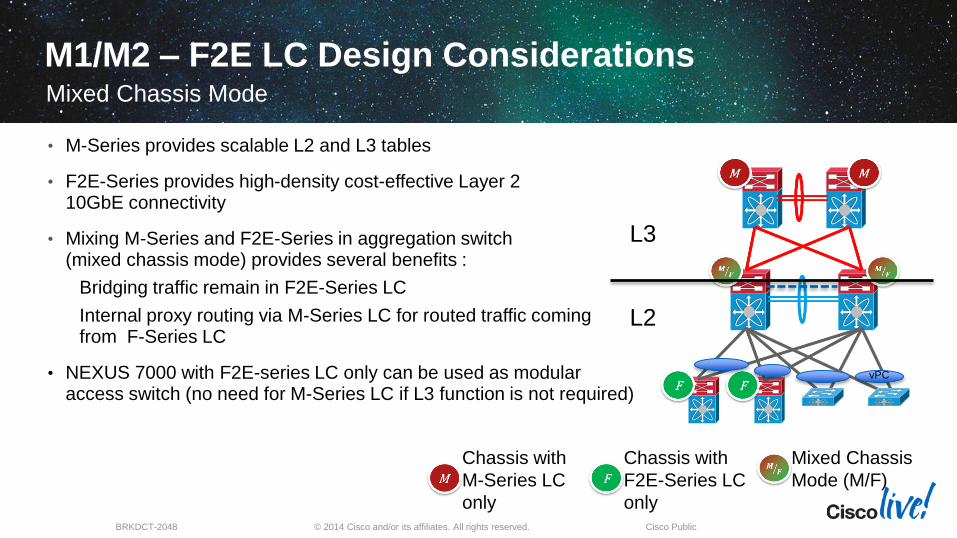
• M-Series provides scalable L2 and L3 tables
• F2E-Series provides high-density cost-effective Layer 2 10GbE connectivity
• Mixing M-Series and F2E-Series in aggregation switch (mixed chassis mode) provides several benefits :
Bridging traffic remain in F2E-Series LC
Internal proxy routing via M-Series LC for routed traffic coming from F-Series LC
• NEXUS 7000 with F2E-series LC only can be used as modular access switch (no need for M-Series LC if L3 function is not required)
L3
L2
Mixed Chassis
Mode (M/F)
Chassis with
F2E-Series LC
only
Chassis with
M-Series LC
only
vPC
M1/M2 – F2E LC Design ConsiderationsMixed Chassis Mode
© 2014 Cisco and/or its affiliates. All rights reserved.BRKDCT-2048 Cisco Public
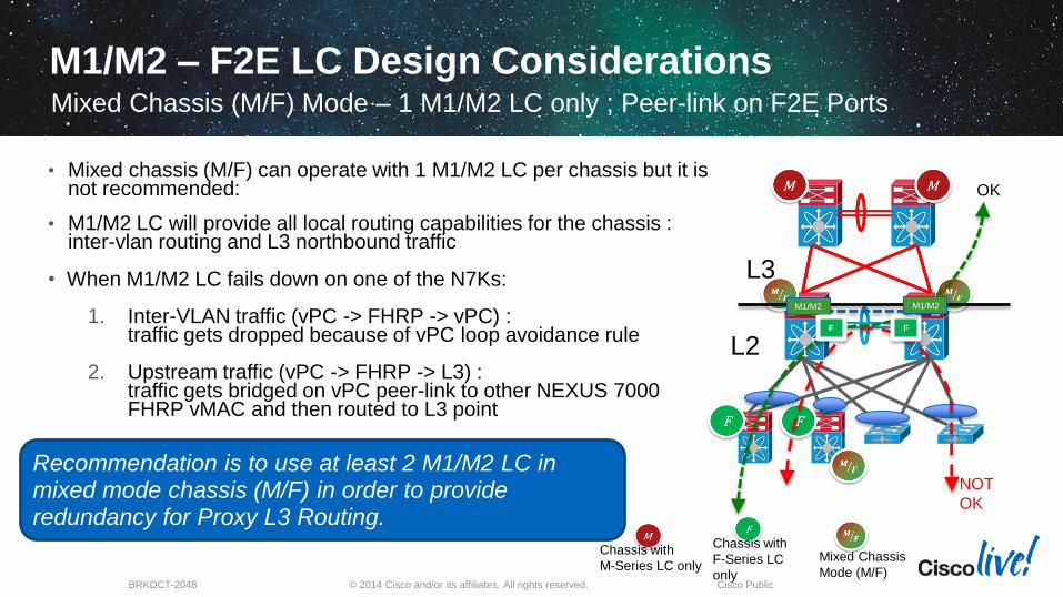
• Mixed chassis (M/F) can operate with 1 M1/M2 LC per chassis but it is not recommended:
• M1/M2 LC will provide all local routing capabilities for the chassis : inter-vlan routing and L3 northbound traffic
• When M1/M2 LC fails down on one of the N7Ks:
1. Inter-VLAN traffic (vPC -> FHRP -> vPC) : traffic gets dropped because of vPC loop avoidance rule
2. Upstream traffic (vPC -> FHRP -> L3) : traffic gets bridged on vPC peer-link to other NEXUS 7000 FHRP vMAC and then routed to L3 point
L3
L2
Chassis with
F-Series LC
only
Chassis with
M-Series LC only
M1/M2
OK
NOT
OK
F F
M1/M2 – F2E LC Design ConsiderationsMixed Chassis (M/F) Mode – 1 M1/M2 LC only ; Peer-link on F2E Ports
Recommendation is to use at least 2 M1/M2 LC in mixed mode chassis (M/F) in order to provideredundancy for Proxy L3 Routing.
M1/M2
Mixed Chassis
Mode (M/F)
© 2014 Cisco and/or its affiliates. All rights reserved.BRKDCT-2048 Cisco Public
M1/M2 - F1/F2/F2e LC Design Considerations
vPC Peer-link
S1 S2
vPC Primary vPC Secondary
M M
vPC
vPC Peer-linkS
1
S
2
vPC Primary vPC Secondary
F2e F2e
vPC
vPC Peer-linkS
1
S
2
vPC Primary vPC Secondary
M F2e
vPC
Always use identical
line cards on either sides of the vPC Peer Link and vPClegs !
M M M MM M M M
M F2e
F2e F2e
© 2014 Cisco and/or its affiliates. All rights reserved.BRKDCT-2048 Cisco Public
M/F2E – NX-OS 6.2(2) and Onwards
vPC Peer-link
S1 S2
vPC Primary vPC Secondary
M M
vPC
vPC Peer-linkS
1
S
2
vPC Primary vPC Secondary
F2e F2e
vPC
vPC Peer-linkS
1
S
2
vPC Primary vPC Secondary
F2e F2e
vPC
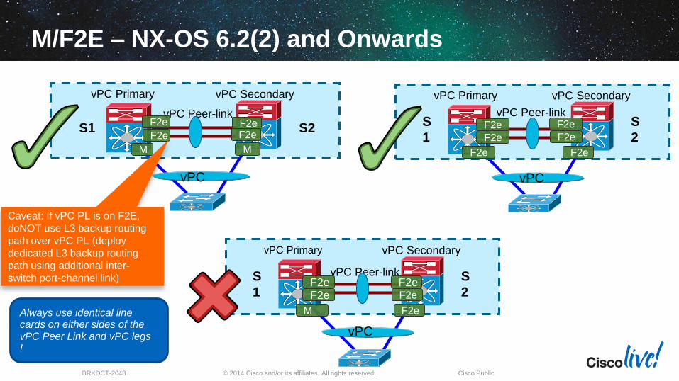
Always use identical line cards on either sides of the vPC Peer Link and vPC legs !
F2e F2e F2e F2eF2e F2e F2e F2e
F2e F2e
M F2e
Caveat: If vPC PL is on F2E,
doNOT use L3 backup routing
path over vPC PL (deploy
dedicated L3 backup routing
path using additional inter-
switch port-channel link)
© 2014 Cisco and/or its affiliates. All rights reserved.BRKDCT-2048 Cisco Public
vPC Peer-link
S1 S2
vPC Primary vPC Secondary
vPC
vPC Peer-link
S1 S2
vPC Primary vPC Secondary
F2 F2
vPC
vPC Peer-linkS
1
S
2
vPC Primary vPC Secondary
F2
F2
vPC
Always use identical VDC type on bothvPC peer devices
F2 F2
F2 F2
F2e
VDC type: F2E
VDC type: F2E
VDC type: F2
VDC type: F2
VDC type: F2 F2E
VDC type: F2
F2
F2
F2 F2
F2/F2E VDC – NX-OS 6.2(2) and Onwards
F2e F2e
F2e
F2e F2e

© 2014 Cisco and/or its affiliates. All rights reserved.BRKDCT-2048 Cisco Public
F2/F2E VDC – NX-OS 6.2(2) and Onwards
vPC Peer-link
S1 S2
vPC Primary vPC Secondary
F2e
vPC
vPC Peer-linkS
1
S
2
vPC Primary vPC Secondary
F2e F2e
vPC
vPC Peer-linkS
1
S
2
vPC Primary vPC Secondary
F2e F2
vPC
Always use identical VDC type on both vPCpeer devices
F2e F2 F2 F2F2
F2e F2 F2e F2VDC type: F2 F2E
VDC type: F2 F2E
VDC type: F2 F2E
VDC type: F2 F2E
F2e F2
F2e F2
VDC type: F2E
VDC type: F2
© 2014 Cisco and/or its affiliates. All rights reserved.BRKDCT-2048 Cisco Public
F2/F2E – NX-OS 6.2(2) and Onwards
Always use identical VDC type on both vPC peer devices
vPC Peer-linkS
1
S
2
vPC Primary vPC Secondary
F2 F2
vPC
F2 F2
F2e F2e
VDC type: F2 F2E
VDC type: F2 F2E
© 2014 Cisco and/or its affiliates. All rights reserved.BRKDCT-2048 Cisco Public
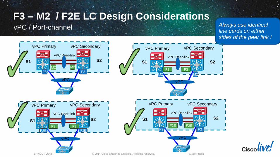
F3 – M2 / F2E LC Design ConsiderationsvPC / Port-channel
vPC Peer-link
S1 S2
vPC Primary vPC Secondary
F3 F3
vPC
Always use identical line cards on either sides of the peer link !
M2
vPC Peer-link
S1 S2
vPC Primary vPC Secondary
F2E
vPC
F2E
F3 F3
M2
vPC Peer-link
S1 S2
vPC Primary vPC Secondary
M2M2
vPC
F3 F3
vPC Peer-link
S1 S2
vPC Primary vPC Secondary
F3 F3
vPC
F2E F2E
© 2014 Cisco and/or its affiliates. All rights reserved.BRKDCT-2048 Cisco Public
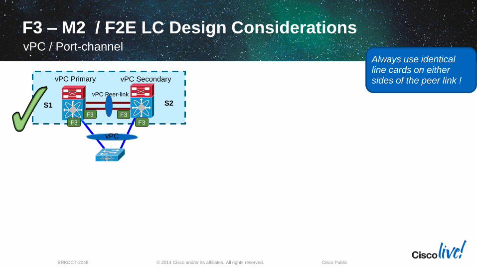
F3 – M2 / F2E LC Design ConsiderationsvPC / Port-channel
vPC Peer-link
S1 S2
vPC Primary vPC Secondary
F3
vPC
Always use identical line cards on either sides of the peer link !
F3
F3 F3
© 2014 Cisco and/or its affiliates. All rights reserved.BRKDCT-2048 Cisco Public
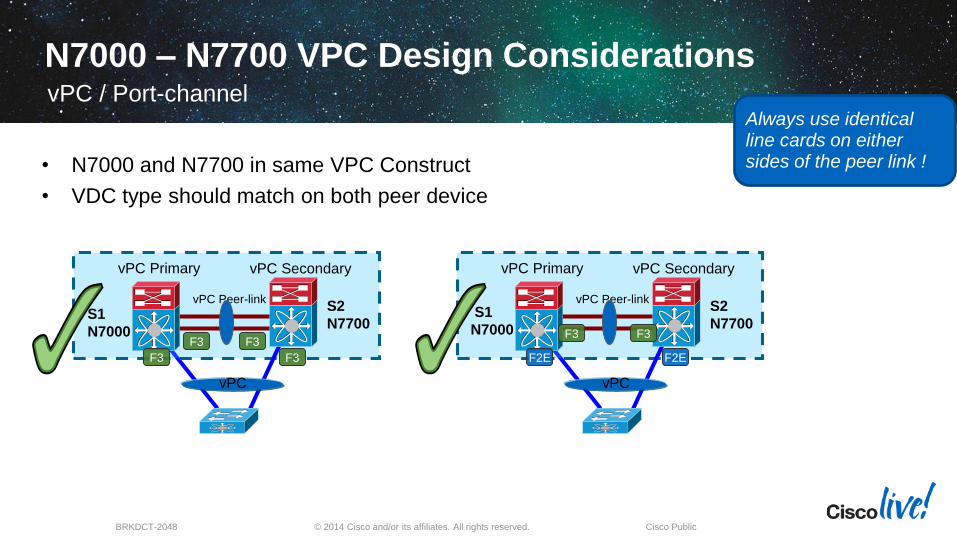
N7000 – N7700 VPC Design ConsiderationsvPC / Port-channel
vPC Peer-link
S1
N7000
S2
N7700
vPC Primary vPC Secondary
vPC
Always use identical line cards on either sides of the peer link !• N7000 and N7700 in same VPC Construct
• VDC type should match on both peer device
vPC Peer-linkS1
N7000
S2
N7700
vPC Primary vPC Secondary
F2E
vPC
F3 F3
F3 F3
F3
F2E
F3

© 2014 Cisco and/or its affiliates. All rights reserved.BRKDCT-2048 Cisco Public
N7000 – N7700 VPC Design ConsiderationsvPC / Port-channel
vPC Peer-link
S1
N7000
S2
N7700
vPC Primary vPC Secondary
F3
vPC
Always use identical line cards on either sides of the peer link !• N7000 and N7700 in same VPC Construct
• VDC type should match on both peer device
vPC Peer-link
S1
N7000
S2
N7700
vPC Primary vPC Secondary
F2E F2E
vPC
F2EF3
F2E
F2E
F2E
© 2014 Cisco and/or its affiliates. All rights reserved.BRKDCT-2048 Cisco Public
M1/M2 - F1/F2/F2e LC Design ConsiderationsvPC / Port-channel
vPC Peer-link
S1 S2
vPC Primary vPC Secondary
F1 F2
vPC
vPC Peer-link
S1 S2
vPC Primary vPC Secondary
F1/ F2 M1
vPC
vPC Peer-link
S1 S2
vPC Primary vPC Secondary
M2M1
vPC
vPC Peer-link
S1 S2F2 F2e
vPC
Always use identical line cards on either sides of the peer link !

AppendixvPC Hardware Support
© 2014 Cisco and/or its affiliates. All rights reserved.BRKDCT-2048 Cisco Public
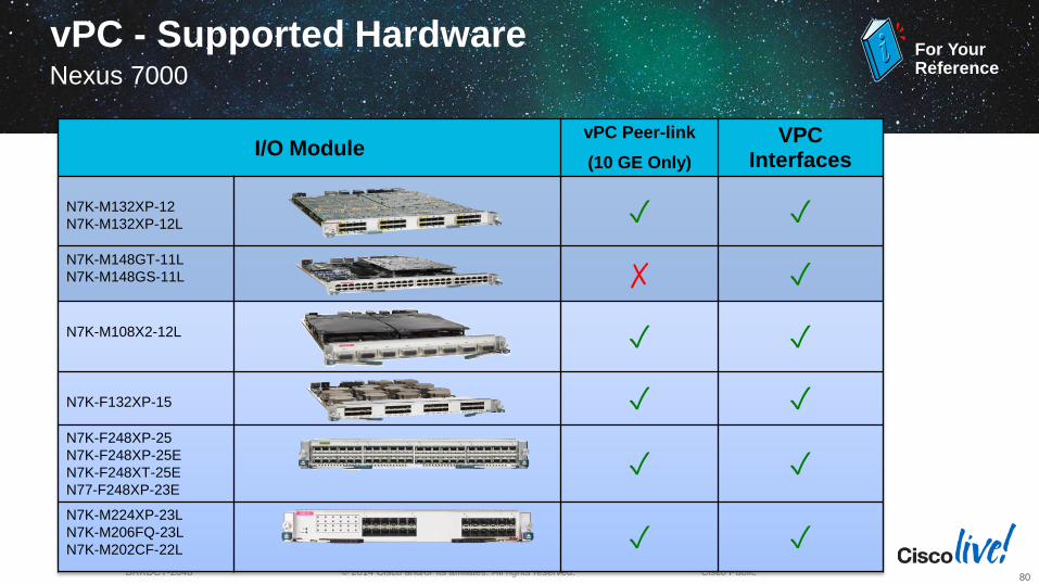
vPC - Supported HardwareNexus 7000
80
I/O ModulevPC Peer-link
(10 GE Only)
VPC Interfaces
N7K-M132XP-12
N7K-M132XP-12L ✓ ✓
N7K-M148GT-11L
N7K-M148GS-11L ✗ ✓
N7K-M108X2-12L ✓ ✓
N7K-F132XP-15 ✓ ✓N7K-F248XP-25
N7K-F248XP-25E
N7K-F248XT-25E
N77-F248XP-23E
✓ ✓
N7K-M224XP-23L
N7K-M206FQ-23L
N7K-M202CF-22L ✓ ✓
For YourReference
© 2014 Cisco and/or its affiliates. All rights reserved.BRKDCT-2048 Cisco Public
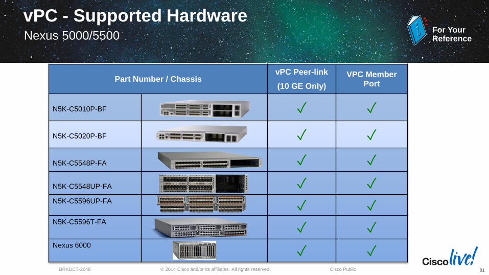
Part Number / ChassisvPC Peer-link
(10 GE Only)
VPC Member Port
N5K-C5010P-BF ✓ ✓
N5K-C5020P-BF ✓ ✓
N5K-C5548P-FA ✓ ✓
N5K-C5548UP-FA ✓ ✓N5K-C5596UP-FA
✓ ✓N5K-C5596T-FA
✓ ✓Nexus 6000
✓ ✓
For YourReference
vPC - Supported HardwareNexus 5000/5500
81
© 2014 Cisco and/or its affiliates. All rights reserved.BRKDCT-2048 Cisco Public
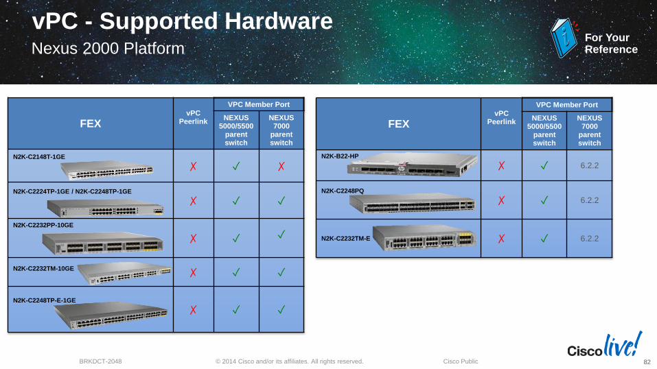
FEXvPC
Peerlink
VPC Member Port
NEXUS 5000/5500
parent switch
NEXUS 7000
parent switch
N2K-C2148T-1GE
✗ ✓ ✗
N2K-C2224TP-1GE / N2K-C2248TP-1GE
✗ ✓ ✓
N2K-C2232PP-10GE
✗ ✓ ✓
N2K-C2232TM-10GE✗ ✓ ✓
N2K-C2248TP-E-1GE
✗ ✓ ✓
For YourReference
vPC - Supported HardwareNexus 2000 Platform
82
FEXvPC
Peerlink
VPC Member Port
NEXUS 5000/5500
parent switch
NEXUS 7000
parent switch
N2K-B22-HP
✗ ✓ 6.2.2
N2K-C2248PQ
✗ ✓ 6.2.2
N2K-C2232TM-E ✗ ✓ 6.2.2

AppendixConvergence & Scalability
© 2014 Cisco and/or its affiliates. All rights reserved.BRKDCT-2048 Cisco Public
vPC Scalability
For Latest Scalability numbers please refer to the scalability limits pages for the platform
Nexus 7000/7700:
N7K Verified Scalability Guide :
http://www.cisco.com/en/US/docs/switches/datacenter/sw/verified_scalability/b_Cisco_Nexus_7000_Series_NX-OS_Verified_Scalability_Guide.html
Nexus 5000 /5500 http://www.cisco.com/en/US/docs/switches/datacenter/nexus5000/sw/configuration_limits/limits_521/nexus_5000_config_limits_521.html
Nexus 6000 http://www.cisco.com/en/US/docs/switches/datacenter/nexus6000/sw/configuration_limits/b_N6000_Verified_Scalability_602N11.pdf
Nexus 3000 http://www.cisco.com/en/US/docs/switches/datacenter/nexus3000/sw/configuration_limits/503_u5_1/b_Nexus3k_Verified_Scalability_503U51.html
84
© 2014 Cisco and/or its affiliates. All rights reserved.BRKDCT-2048 Cisco Public
Attaching to a vPC Domain
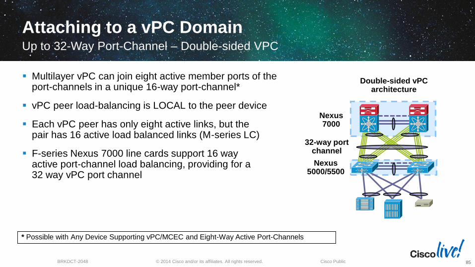
Multilayer vPC can join eight active member ports of the port-channels in a unique 16-way port-channel*
vPC peer load-balancing is LOCAL to the peer device
Each vPC peer has only eight active links, but the pair has 16 active load balanced links (M-series LC)
F-series Nexus 7000 line cards support 16 way active port-channel load balancing, providing for a 32 way vPC port channel
Up to 32-Way Port-Channel – Double-sided VPC
85
Nexus 7000
Nexus 5000/5500
32-way port channel
* Possible with Any Device Supporting vPC/MCEC and Eight-Way Active Port-Channels
Double-sided vPC architecture

AppendixLayer 3 and vPC
© 2014 Cisco and/or its affiliates. All rights reserved.BRKDCT-2048 Cisco Public
Routing Protocol Peer
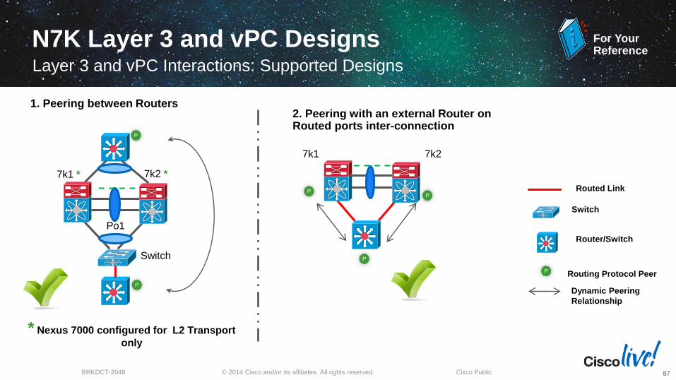
N7K Layer 3 and vPC DesignsLayer 3 and vPC Interactions: Supported Designs
87
Switch
7k1 *
Po1
7k2 *
P
P
Router/Switch
1. Peering between Routers
7k1 7k2
Dynamic Peering
Relationship
2. Peering with an external Router on Routed ports inter-connection
P
P
Switch
P Routed Link
P
* Nexus 7000 configured for L2 Transport
only
For YourReference
© 2014 Cisco and/or its affiliates. All rights reserved.BRKDCT-2048 Cisco Public
N7K Layer 3 and vPC Designs Layer 3 and vPC Interactions: Supported Designs
88
P
P P
7k1 7k2
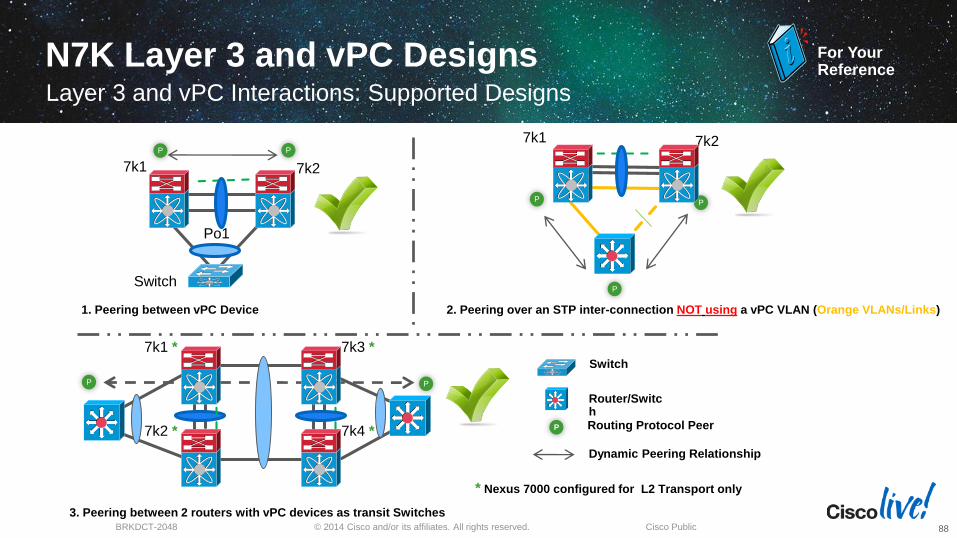
2. Peering over an STP inter-connection NOT using a vPC VLAN (Orange VLANs/Links)
7k1 *
7k2 *
7k3 *
7k4 *
3. Peering between 2 routers with vPC devices as transit Switches
P P
Switch
7k1
Po1
7k2
1. Peering between vPC Device
PP
Routing Protocol Peer
Router/Switch
P
Dynamic Peering Relationship
Switch
* Nexus 7000 configured for L2 Transport only
For YourReference

© 2014 Cisco and/or its affiliates. All rights reserved.BRKDCT-2048 Cisco Public
N7K Layer 3 and vPC DesignsLayer 3 and vPC Interactions: Supported Designs
89
7k1
PP
P P
7k2
7k3
7k4
2. Peering over a vPC inter-connection (DCI case) on parallel Routed ports
inter-connection1. Peering with an external Router on parallel Routed ports inter-connection
P
7k1 7k2
P
P
7k1
Po1
7k2
PP
P P
3. Peering over PC inter-connection and dedicated inter-switch link using non-
vPC VLAN
For YourReference
© 2014 Cisco and/or its affiliates. All rights reserved.BRKDCT-2048 Cisco Public
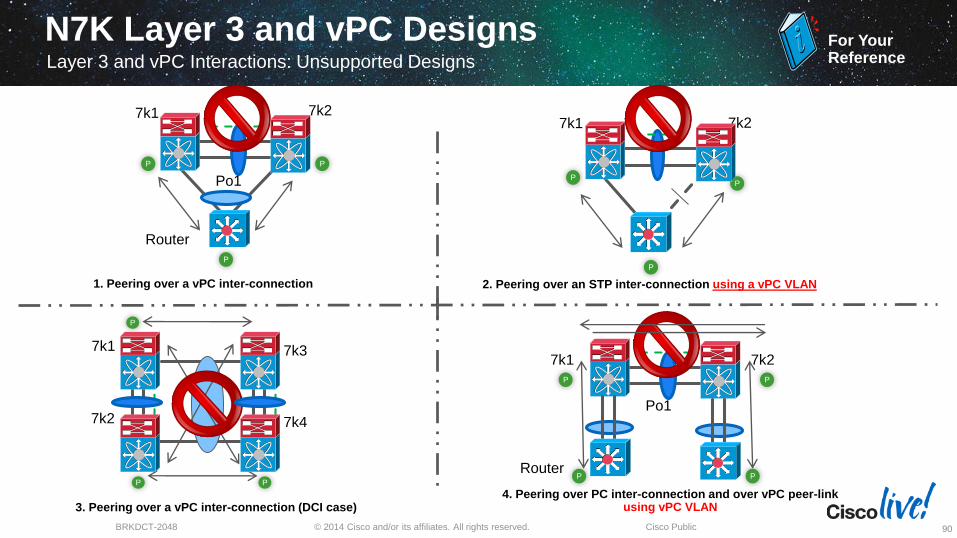
N7K Layer 3 and vPC Designs Layer 3 and vPC Interactions: Unsupported Designs
90
Router
7k1
Po1
7k2
PP
P
4. Peering over PC inter-connection and over vPC peer-link using vPC VLAN
P
PP
7k1 7k2
2. Peering over an STP inter-connection using a vPC VLAN
7k1
P
P P
7k2
7k3
7k4
3. Peering over a vPC inter-connection (DCI case)
Router
7k1
Po1
7k2
PP
P
1. Peering over a vPC inter-connection
P
For YourReference

AppendixReference Material
© 2014 Cisco and/or its affiliates. All rights reserved.BRKDCT-2048 Cisco Public
Reference Material
92
For YourReference
vPC white Paper:
http://www.cisco.com/en/US/prod/collateral/switches/ps9441/ps9402/white_paper_c11-516396.html
vPC design guides:
http://www.cisco.com/en/US/partner/products/ps9670/products_implementation_design_guides_list.html
vPC and VSS Interoperability white Paper:
http://www.cisco.com/en/US/prod/collateral/switches/ps5718/ps708/white_paper_c11_589890.html
Data Centre Design—IP Network Infrastructure:
http://www.cisco.com/en/US/docs/solutions/Enterprise/Data_Center/DC_3_0/DC-3_0_IPInfra.html
Layer 2 Extension Between Data Centres:
http://www.cisco.com/en/US/prod/collateral/switches/ps5718/ps708/white_paper_c11_493718.html
Implementing Nexus 7000 in the Data Centre Aggregation Layer with Services:
https://www.cisco.com/en/US/docs/solutions/Enterprise/Data_Center/nx_7000_dc.html
VPC Best Practices Design Guide: http://www.cisco.com/en/US/docs/switches/datacenter/sw/design/vpc_design/vpc_best_practices_design_guide.pdf
VPC Software Upgrade Technical Note
http://www.cisco.com/en/US/docs/switches/datacenter/sw/nx-os/tech_note/vpc_upgrade.html
Follow us on Twitter @CiscoNexus7000 Official Cisco Nexus 7000 Channel
New
New