Embed Size (px)
Citation preview
Depth Image Based Rendering with InverseMapping
Muhammad Shahid Farid, Maurizio Lucenteforte, Marco Grangetto
Dipartimento di Informatica, Universita di TorinoCorso Svizzera 185, 10149 Torino, ITALY
Abstract—Three-dimensional video has gained much attentionduring the last decade due its vast applications in cinema, tele-vision, animation and virtual reality. The design of intermediateview synthesis algorithms that are efficient both in terms ofcomputational complexity and visual quality is a paramount goalin the fields of 3D free view point television and displays. Thispapers focuses on the design of a low complexity view synthesisalgorithm that produces better quality of the virtual image. Anovel view synthesis technique to create a virtual view fromtwo video sequences with corresponding depths is proposed.The technique employs low complexity integer pixel precisionwarping and a novel approach for hole filling based on inversemapping. The proposed technique is tested over a number ofvideo sequences and compared with existing state of the artmethods, yielding excellent results both in terms of signal tonoise ratio and visual quality.
Index Terms—3D-TV, Depth image based rendering, Viewsynthesis, 3D warping
I. INTRODUCTION
The quest for novel and efficient 3D video representationsand coding techniques in area of 3D television (3DTV) hasrecently revitalized the research in the area of intermediateview synthesis. In fact, emerging 3D display technologies,such as autostereoscopic displays, require the availability ofseveral images corresponding to different point of views. Itturns out that the possibility to synthesize intermediate viewsfrom a limited set of original video sequences has gained muchattention in the last years. View synthesis has the potentialto greatly reduce the amount of video data to be transmittedand can be integrated in the common hybrid predictive codingapproaches to capture the inter-view redundancy.
The concept of creating a virtual view from two or moreviews has been coined in the computer vision literature almostfour decades ago [1] using different terms like view synthesis[2], view morphing [3] and image metamorphosis [4]. Anumber of techniques to create a virtual view from two ormore views have been proposed. They may be classified intothree broad categories [5]. Any view can be generated if thescene is represented with its 3D structure, which is usually notreasonable for natural video shots. The second class, knownas depth image based rendering (DIBR), uses a number ofviews with implicit geometry like depth of the scene to createintermediate views [6], [7]. In the third category, only images
MMSP’13, Sept. 30 - Oct. 2, 2013, Pula (Sardinia), Italy.
are used to create a new view without depth or geometryinformation like [8]. The view synthesis technique proposedin this paper falls in the second category: in particular, weconsider the common problem to estimate an intermediateview in between two original views plus the correspondingdepth maps. All DIBR techniques comprise two main algorith-mic steps; first, the intermediate virtual view is generated bywarping the original pixels to the corresponding intermediatepositions, based on depths and camera parameters. After that,two warped views are blended to create a single virtual view.Because of geometrical occlusions, depth imprecision and/orlossy coding of depth there may still be some pixels of thevirtual view which are uninitialized, referred to as holes. InDIBR, the second step consists in estimating such missingpixels usually exploiting image inpainting techniques.
Many DIBR techniques have been proposed so far. Anextensive review can be found in [9], [10]. Minh Do et. al.[11] proposed an intensity propagation algorithm to generate avirtual view from two views with their depths. Their algorithmworks in three steps. In first step, without considering theocclusions all pixels of a view are warped to the new positions.In second step, the occluded pixels are identified with the helpof their depth. In the final step, the occluded pixels’ intensitiesare interpolated using a cubic spline function. To computethe intensities in occluded regions, texture based approach isproposed in [12]. Texture based synthesis normally generatesbetter visual quality in case of large size occlusions but canbe very expensive in terms of computational costs makingit unfeasible in real time applications. Hofsetz et. al. [13]presented a technique for view synthesis when the depth mapsare not accurate. The regions with inaccurate depths are termedas uncertain regions. Their approach is to determine these re-gions and then apply 3D ellipsoidal Gaussian kernels to renderthe virtual view. Schmeing and Jiang [14] proposed an imagebased rendering technique that first estimate the backgroundand uses the segmentation results to fill the occluded regions.This technique yields accurate results in the particular case ofscenes with only two depth layers. A number of techniqueshave been developed to recover synthesis holes. A hole fillingalgorithm that uses pixels’ depths and intensities to computethe occluded regions has been presented in [15]. Anothertechnique to compute the occluded regions by registering thetwo views has been presented in [16]. In [17] foreground andbackground weights are used to interpolate the missing pixel.
Finally, [18], [19], [20] exploits inpainting techniques. Mostof the mentioned techniques have led to the development ofView Synthesis Reference Software (VSRS) [21] by the 3DVMPEG group and that will be used as a benchmark for ourexperiments.
This major contribution of this paper is a novel low com-plexity View Synthesis with Inverse Mapping (VSIM), whichyields competitive results as compared to state of the artVSRS. As opposed to more complex solutions, VSIM achievesexcellent results applying warping with integer pixel precisionand recovering synthesis holes using a novel inverse-mappingfunction.
The rest of the paper is organized as follows. In Sect. II theproposed algorithm for virtual view generation is presented. InSect. III experimental results and comparisons with existingtechniques are shown and in Sect. IV our conclusions aredrawn.
II. PROPOSED VIEW SYNTHESIS WITH INVERSE MAPPING(VSIM) TECHNIQUE
The proposed VSIM algorithm works in two steps like otherview synthesis algorithm. It takes two views with depths (leftview and right view) as input and computes the intermediatevirtual view. Each input view is warped to the intermediate po-sition and the two resultant virtual views are merged togetherto get a single virtual view. While warping the original viewsto intermediate positions, a mapping function is defined againsteach warped view. The missing pixels are then computed withthe help of the mapping functions. The proposed algorithmassumes the usual horizontal shift camera setup. The followingsubsections describe the algorithm.
A. Pixel warping
Let vL and vR be left and right original views of size m×n, and dL, dR the respective depth maps. Let fL and fRbe the camera focal lengths, and bL, bR the position of thetwo cameras on the base line, i.e. their disparity is equal b =bR− bL. Usually, the depth maps are provided as 256 levelsimages where values 0 and 255 represents the farthest andnearest depths, respectively. The true depth values dL′ (dR′)are recovered from the encoded depth map dL (dR) using thefollowing equation:
dL′ =1
dL255 (
1zNear −
1zFar ) +
1zFar
(1)
where zNear and zFar are the nearest and farthest depths inthe scene.
Since the cameras are parallel with baseline b, the positionof the virtual camera for intermediate view is bL+ b
2 (= bR− b2 )
and original image pixels can be warped to intermediate viewposition by applying horizontal shifts that depend on the theirdepth values. If we let (u, v) represent the coordinates of agiven pixel in the view (vL), then the coordinates of the samepixel in the left virtual view (vL′) turns to be (u′, v′) = (u, v′)with:
v′ = v − fL× b
dL′(u, v)(2)
The value fL×bdL′(u,v) is usually termed column shift. Column
shift will be subtracted from the pixel column value to findits position in the virtual view because the considered pixel inthe left view will move leftward in the coordinate system ofthe virtual view. Similarly, in case of right virtual view (vR′),the column shift would be added to the pixel column value.
Using Eq. 2, the warped positions of each pixel can beeasily computed. During warping more than one pixels fromthe original view may map to the same position in the virtualview. In this case only the foremost pixel (the one with thelargest depth) will be considered. It is also possible that somelocations in the virtual view remain empty, i.e. synthesis holes:these positions represent pixels that look occluded from theoriginal view point or they can be caused by warping errorsdue to depth estimation or quantization errors.
Once the left virtual view vL′ and right virtual view vR′
have been computed applying horizontal warping, a singleintermediate virtual view vM is obtained by merging the twoimages according to the following equation:
vM(u, v) =
vL′(u,v)+vR′(u,v)
2, if hL(u, v) = hR(u, v) = 0
vL′(u, v), if hL(u, v) = 0 ∧ hR(u, v) = 1
vR′(u, v), if hL(u, v) = 1 ∧ hR(u, v) = 0
0, otherwise(3)
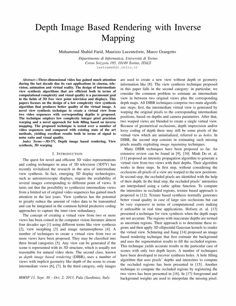
where hL (hR) is a binary map identifying the holes in the left(right) virtual view. According to previous equation only thosepixels that are missing in both the virtual views will appear asholes in the merged view vM . A binary map holesV is usedto identify the location of these holes. Fig. 1 shows the wholewarping process schematically.
dL’ vL
dR’ vR
Compute Left Virtual
View, holesL, shiftL
Compute Right Virtual
View, holesR, shiftR
holesR
shiftR
vR’
holesL
shiftL
vL’
Merge the left and right
virtual views
Inverse Mapping Function
vM: Final Virtual View
holesV
vM
Fig. 1: Schematic diagram of the proposed technique.
B. Holes filling through inverse mapping
Not all the pixels of the virtual view can be recovered forthree main reasons that are recalled in the following.

1) Holes due to inaccurate depth: the depth maps maycontain some errors as they are usually estimated andthen quantized to 256 levels. Because of inaccuratedepth values erroneous shifts may be applied to thepixel locations. Some warping techniques proposed inliterature try to limit this effect by smoothing the depthmaps before warping.
2) Cracks: the warping process does not warp the objectsor surfaces as whole and this may introduce holes inthe surface (we name them cracks). These cracks canbe recovered by the proposed inverse mapping function.The black lines on the right hand side in Fig. 2 areexample of cracks.
3) Disocclusion: third case is represented by disocclusionsthat appear when an object in the foreground uncovera portion of background that is not visible from theoriginal view points. Such unknown background regionsclearly appear as holes in the virtual view. The greenareas on the right side of Fig. 2 are examples ofdisocclusion.
Fig. 2: Green area in enlarged rectangle on the right side ofthe image is the new region introduced in the scene whereasthe black lines in the enlarged region on the left side of theimage are cracks.
In the DIBR literature holes of the virtual view are recoveredby different techniques, e.g. averaging the neighboring pixels,applying non-linear filters like median filer or by using morecomplex techniques like texture based inpainting. In this paper,we fill the holes by re-mapping their locations in the originalview based on the column-shifts of the neighborhood. Usingsuch information holes can be mapped backward to one of theoriginal views so as to identify the missing pixel values. Wename this technique inverse mapping.
An inverse mapping function can be defined for both theleft and the right virtual view. The function takes a missinghole position as input and returns its approximated position inthe respective original left or right view.To define this functionwe maintain a table that records the column shift of each pixelwith respect to the virtual view. Let shiftL be such a tablefor left virtual view: if vL(u, v) is shifted to position (u, v′)in vL′, then shiftL(u, v′) = v. Similarly, shiftR is used forright virtual view.
The first step in inverse mapping is to determine the originallocations of holes in holesV by trying to interpolate themissing values in the table shiftL (shiftR). To this end,VSIM applies a median filter to shiftL and shiftR. Weverified experimentally that the median filter yields betterresults than average or weighted average filters. In particular,we have observed that the median filters with kernel size 3×3and 5 × 5 produce the best results. The locations recoveredby applying median filter to shiftL and shiftR are used todetermine the pixels of the original views that can be copiedto fill holes of the virtual view. Due to the limited size ofthe median filter some holes cannot be recovered with thismechanism. We observed that iteratively increasing the sizeof the filter to recover all holes generally yields poor shiftinterpolation results with the creation of artifacts in the virtualview. We have found that the few remaining holes can berecovered by simply assuming that their depth is the sameas the co-located pixels in the original views. The detaileddescription of inverse mapping function is shown in Algorithm1.
Algorithm 1 Inverse Mapping Function
Require: vL, vR, vM, holesV, shiftL, shiftR, zInvL,zInvR, f, b
Ensure: vM : Final virtual view after filling the holes1: shiftL′ ← medianfilter(shiftL)2: shiftR′ ← medianfilter(shiftR)3: for (u, v) ∈ holesV do4: v′ = shiftL′(u, v)5: if v′ ≤ m and v′ > 0 then6: vM(u, v)← vL(u, v′)7: else8: v′ = shiftR′(u, v)9: if v′ <= m and v′ > 0 then
10: vM(u, v)← vR(u, v′)11: else12: v′ = round(v + zInvL(u, v)× f × b)13: if v′ <= m and v′ > 0 then14: vM(u, v)← vL(u, v′)15: else16: v′ = round(v − zInvR(u, v)× f × b)17: vM(u, v)← vR(u, v′)18: end if19: end if20: end if21: end for{zInvL and zInvR are 1
dL′ and 1dR′ as we are multiply-
ing it with focal length f and camera base line differenceb. Compare it with Equation 2}
22: return vM : Final intermediate virtual view
III. EXPERIMENTAL EVALUATION
The proposed VSIM technique has been tested over anumber of standard test sequences. VSIM implementationtakes as input two views and their depth maps in YUV(4:2:0)
format and estimate the intermediate view in the same format.The warping phase works using integer pixel precision, i.e. byrounding to nearest integer all shifted column positions. Thechroma components U, V are warped in their native (down-sampled) resolutions as well. The proposed inverse mappingprocedure is then used to fill the holes, independently on eachof the 3 components.
First of all the VSIM technique has been compared withMPEG VSRS reference software using both integer and quar-ter pixel precisions. Tab. I show the experimental settingsreporting sequence name, rendered view index, video reso-lution and total number of rendered frames (NF), along withthe average Luma PSNR yielded by VSIM and VSRS withinteger and quarter pixel precision (see VSRS1 and (VSRS4
columns respectively). It can be observed that VSIM achievesa significant gain over VSRS with integer pixel precisionand exhibits quite similar performance compared to VSRSwith quarter pixel precision. In other words, VSIM favorablycompetes with the reference software without requiring eitherup-sampling or interpolation of the warped views. In order tobetter appreciate the effect of the proposed inverse mappingprocedure an additional set of experiments have been workedout by replacing it with a simple 7 averaging filter (seeVSIMa column in Tab. I). It can be observed that inversemapping yields a noticeable improvement with respect to pixelinterpolation by averaging.
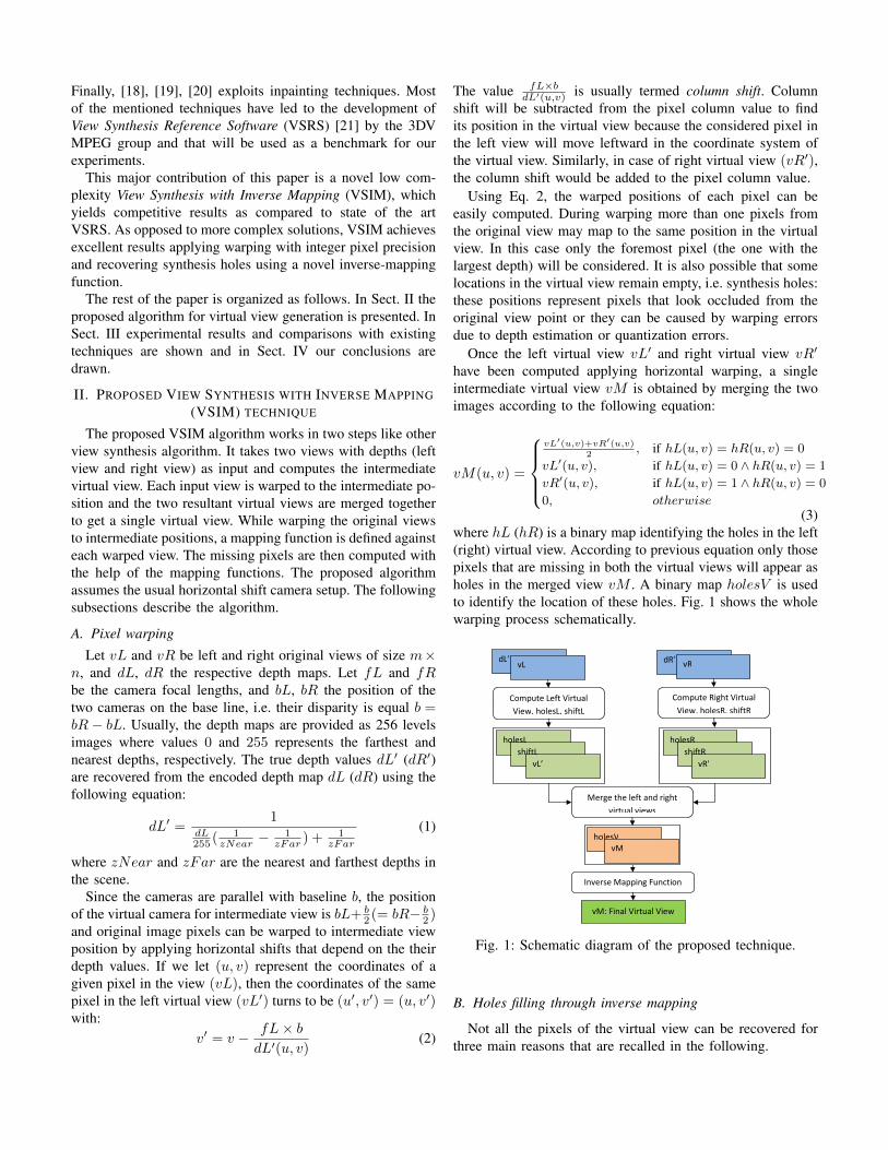
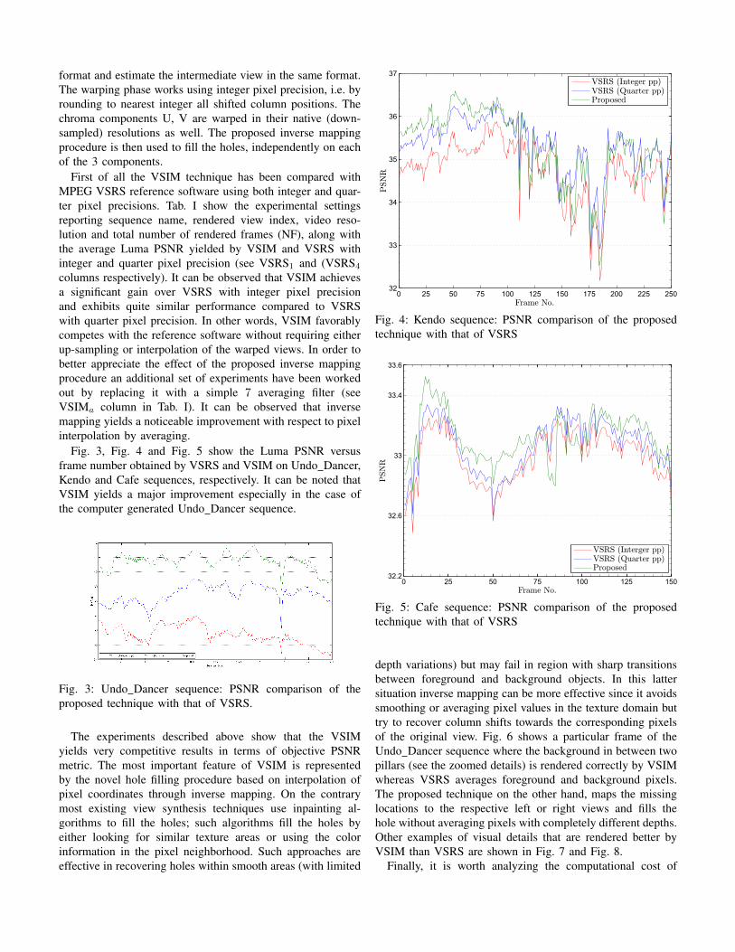
Fig. 3, Fig. 4 and Fig. 5 show the Luma PSNR versusframe number obtained by VSRS and VSIM on Undo Dancer,Kendo and Cafe sequences, respectively. It can be noted thatVSIM yields a major improvement especially in the case ofthe computer generated Undo Dancer sequence.
Fig. 3: Undo Dancer sequence: PSNR comparison of theproposed technique with that of VSRS.
The experiments described above show that the VSIMyields very competitive results in terms of objective PSNRmetric. The most important feature of VSIM is representedby the novel hole filling procedure based on interpolation ofpixel coordinates through inverse mapping. On the contrarymost existing view synthesis techniques use inpainting al-gorithms to fill the holes; such algorithms fill the holes byeither looking for similar texture areas or using the colorinformation in the pixel neighborhood. Such approaches areeffective in recovering holes within smooth areas (with limited
0 25 50 75 100 125 150 175 200 225 25032
33
34
35
36
37
Frame No.
PSN
R
VSRS (Integer pp)VSRS (Quarter pp)Proposed
Fig. 4: Kendo sequence: PSNR comparison of the proposedtechnique with that of VSRS
0 25 50 75 100 125 15032.2
32.6
33
33.4
33.6
Frame No.
PSN
R
VSRS (Interger pp)VSRS (Quarter pp)Proposed
Fig. 5: Cafe sequence: PSNR comparison of the proposedtechnique with that of VSRS
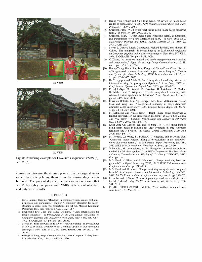
depth variations) but may fail in region with sharp transitionsbetween foreground and background objects. In this lattersituation inverse mapping can be more effective since it avoidssmoothing or averaging pixel values in the texture domain buttry to recover column shifts towards the corresponding pixelsof the original view. Fig. 6 shows a particular frame of theUndo Dancer sequence where the background in between twopillars (see the zoomed details) is rendered correctly by VSIMwhereas VSRS averages foreground and background pixels.The proposed technique on the other hand, maps the missinglocations to the respective left or right views and fills thehole without averaging pixels with completely different depths.Other examples of visual details that are rendered better byVSIM than VSRS are shown in Fig. 7 and Fig. 8.
Finally, it is worth analyzing the computational cost of
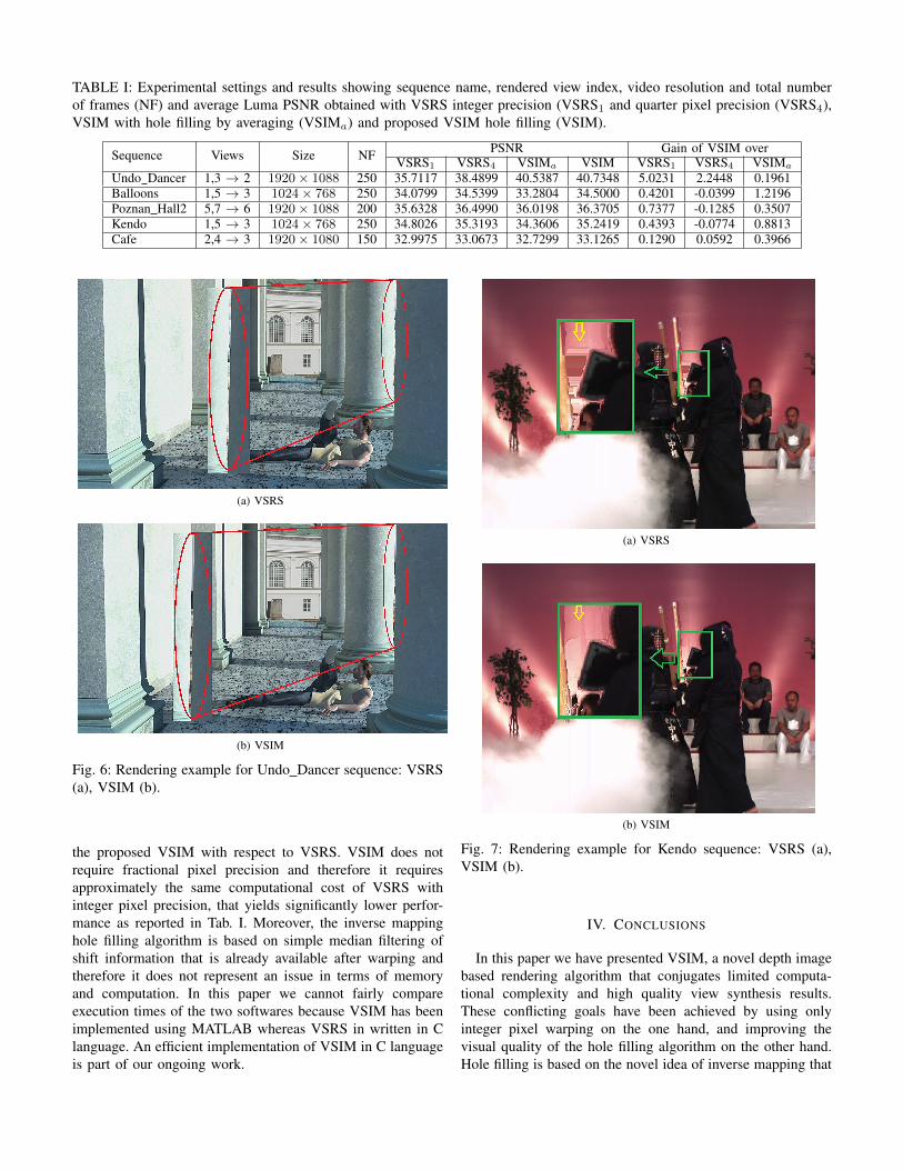
TABLE I: Experimental settings and results showing sequence name, rendered view index, video resolution and total numberof frames (NF) and average Luma PSNR obtained with VSRS integer precision (VSRS1 and quarter pixel precision (VSRS4),VSIM with hole filling by averaging (VSIMa) and proposed VSIM hole filling (VSIM).
Sequence Views Size NF PSNR Gain of VSIM overVSRS1 VSRS4 VSIMa VSIM VSRS1 VSRS4 VSIMa
Undo Dancer 1,3 → 2 1920× 1088 250 35.7117 38.4899 40.5387 40.7348 5.0231 2.2448 0.1961Balloons 1,5 → 3 1024× 768 250 34.0799 34.5399 33.2804 34.5000 0.4201 -0.0399 1.2196Poznan Hall2 5,7 → 6 1920× 1088 200 35.6328 36.4990 36.0198 36.3705 0.7377 -0.1285 0.3507Kendo 1,5 → 3 1024× 768 250 34.8026 35.3193 34.3606 35.2419 0.4393 -0.0774 0.8813Cafe 2,4 → 3 1920× 1080 150 32.9975 33.0673 32.7299 33.1265 0.1290 0.0592 0.3966
(a) VSRS
(b) VSIM
Fig. 6: Rendering example for Undo Dancer sequence: VSRS(a), VSIM (b).
the proposed VSIM with respect to VSRS. VSIM does notrequire fractional pixel precision and therefore it requiresapproximately the same computational cost of VSRS withinteger pixel precision, that yields significantly lower perfor-mance as reported in Tab. I. Moreover, the inverse mappinghole filling algorithm is based on simple median filtering ofshift information that is already available after warping andtherefore it does not represent an issue in terms of memoryand computation. In this paper we cannot fairly compareexecution times of the two softwares because VSIM has beenimplemented using MATLAB whereas VSRS in written in Clanguage. An efficient implementation of VSIM in C languageis part of our ongoing work.
(a) VSRS
(b) VSIM
Fig. 7: Rendering example for Kendo sequence: VSRS (a),VSIM (b).
IV. CONCLUSIONS
In this paper we have presented VSIM, a novel depth imagebased rendering algorithm that conjugates limited computa-tional complexity and high quality view synthesis results.These conflicting goals have been achieved by using onlyinteger pixel warping on the one hand, and improving thevisual quality of the hole filling algorithm on the other hand.Hole filling is based on the novel idea of inverse mapping that
(a) VSRS
(b) VSIM
Fig. 8: Rendering example for LoveBirds sequence: VSRS (a),VSIM (b).
consists in retrieving the missing pixels from the original viewsrather than interpolating them from the surrounding neigh-borhood. The presented experimental evaluation shows thatVSIM favorably compares with VSRS in terms of objectiveand subjective results.
REFERENCES
[1] H. C. Longuet-Higgins, “Readings in computer vision: issues, problems,principles, and paradigms,” chapter A computer algorithm for recon-structing a scene from two projections, pp. 61–62. Morgan KaufmannPublishers Inc., San Francisco, CA, USA, 1987.
[2] Shenchang Eric Chen and Lance Williams, “View interpolation forimage synthesis,” in Proceedings of the 20th annual conference onComputer graphics and interactive techniques, New York, NY, USA,1993, SIGGRAPH ’93, pp. 279–288, ACM.
[3] Steven M. Seitz and Charles R. Dyer, “View morphing,” in Proceedingsof the 23rd annual conference on Computer graphics and interactivetechniques, New York, NY, USA, 1996, SIGGRAPH ’96, pp. 21–30,ACM.
[4] George Wolberg, Digital Image Warping, IEEE Computer Society Press,Los Alamitos, CA, USA, 1st edition, 1990.
[5] Heung-Yeung Shum and Sing Bing Kang, “A review of image-basedrendering techniques,” in IEEE/SPIE Visual Communications and ImageProcessing (VCIP), 2000.
[6] Christoph Fehn, “A 3d-tv approach using depth-image-based rendering(dibr),” in Proc. of VIIP, 2003, vol. 3.
[7] Christoph Fehn, “Depth-image-based rendering (dibr), compression,and transmission for a new approach on 3d-tv,” in Proc. SPIE 5291,Stereoscopic Displays and Virtual Reality Systems XI, 93 (May 21,2004), April 2004.
[8] Steven J. Gortler, Radek Grzeszczuk, Richard Szeliski, and Michael F.Cohen, “The lumigraph,” in Proceedings of the 23rd annual conferenceon Computer graphics and interactive techniques, New York, NY, USA,1996, SIGGRAPH ’96, pp. 43–54, ACM.
[9] C. Zhang, “A survey on image-based renderingrepresentation, samplingand compression,” Signal Processing: Image Communication, vol. 19,no. 1, pp. 1–28, Jan. 2004.
[10] Heung-Yeung Shum, Sing Bing Kang, and Shing-Chow Chan, “Surveyof image-based representations and compression techniques,” Circuitsand Systems for Video Technology, IEEE Transactions on, vol. 13, no.11, pp. 1020–1037, 2003.
[11] Ha T. Nguyen and Minh N. Do, “Image-based rendering with depthinformation using the propagation algorithm,” in in Proc. IEEE Int.Conf. Acoust., Speech, and Signal Proc, 2005, pp. 589–592.
[12] P. Ndjiki-Nya, M. Koppel, D. Doshkov, H. Lakshman, P. Merkle,K. Muller, and T. Wiegand, “Depth image-based rendering withadvanced texture synthesis for 3-d video,” Trans. Multi., vol. 13, no. 3,pp. 453–465, June 2011.
[13] Christian Hofsetz, Kim Ng, George Chen, Peter McGuinness, NelsonMax, and Yang Liu, “Image-based rendering of range data withestimated depth uncertainty,” IEEE Comput. Graph. Appl., vol. 24, no.4, pp. 34–42, July 2004.
[14] M. Schmeing and Xiaoyi Jiang, “Depth image based rendering: Afaithful approach for the disocclusion problem,” in 3DTV-Conference:The True Vision - Capture, Transmission and Display of 3D Video(3DTV-CON), 2010, June, pp. 1–4.
[15] Kwan-Jung Oh, Sehoon Yea, and Yo-Sung Ho, “Hole filling methodusing depth based in-painting for view synthesis in free viewpointtelevision and 3-d video,” in Picture Coding Symposium, 2009. PCS2009, May, pp. 1–4.
[16] M. Koppel, Xi Wang, D. Doshkov, T. Wiegand, and P. Ndjiki-Nya,“Consistent spatio-temporal filling of disocclusions in the multiview-video-plus-depth format,” in Multimedia Signal Processing (MMSP),2012 IEEE 14th International Workshop on, Sept., pp. 25–30.
[17] V. Paradiso, M. Lucenteforte, and M. Grangetto, “A novel interpolationmethod for 3d view synthesis,” in 3DTV-Conference: The True Vision- Capture, Transmission and Display of 3D Video (3DTV-CON), 2012,Oct., pp. 1–4.
[18] M.S. Farid, H. Khan, and A. Mahmood, “Image inpainting based onpyramids,” in Signal Processing (ICSP), 2010 IEEE 10th InternationalConference on, Oct., pp. 711–715.
[19] M.S. Farid and H. Khan, “Image inpainting using dynamic weightedkernels,” in Computer Science and Information Technology (ICCSIT),2010 3rd IEEE International Conference on, July, vol. 8, pp. 252–255.
[20] I. Daribo and H. Saito, “A novel inpainting-based layered depth videofor 3dtv,” Broadcasting, IEEE Transactions on, vol. 57, no. 2, pp. 533–541, 2011.
[21] ISO/IEC JTC1/SC29/WG11 (MPEG), “View synthesis reference soft-ware (vsrs) 3.5,” Mar. 2010.