Embed Size (px)
Citation preview
DES I G N SURVEY OF THE
APOLLO INERTIAL SUBSYSTEM
Edited by William A. Stameris ' A
GUIDANCE, NAVIGATION AND CONTROL
Date:
ION PROGRAM
Approved:, ,@, x- ~ ~ t e : 3 , ~ 4 f l 76' R. R. RAGAN, (IJEPUTY DIR&TOR CHARLES STARK DRAPER LABORATORY
DESIGN SURVEY OF THE
APOLLO INERTIAL SUBSYSTEM
Edi ted b37
Wil l iam A. S t a m e r i s
MARCH 1970
HARLES STARK DRAPER -- -
CAMBRIDGE, MASSACHUSETTS, 02139 LABORATORY
ACKNOWLEDGEMENT
This r epor t was compiled and edited by William A. Stameris and
Paul F. Jopling of the Char les Stark Draper Laboratory, Massachusetts
Institute of Technology. It was prepared under DSR Projects 55-31650
and 55-23870, sponsored by the Electronics Research Center and the Man-
ned Spacecraft Center of the National Aeronautics and Space Administration
under contracts NAS 12-642 and NAS 9-4065 with the Massachusetts Institute
of Technology.
The publication of this repor t does not constitute approval by the
National Aeronautics and Space Administration of the findings o r the con-
clusions contained herein. It i s published solely for the exchange and
stimulation of ideas.
E - 2500
INERTIAL SUBSYSTEM DESIGN SURVEY
ABSTRACT
This document E - 2500 is a recorded history of the design
and development of the Apollo inert ial subsystem (CSM, LM)
intended fo r manned spaceflight beyond earth orbits .
I t s purpose is a source document for subsequent design
c r i t e r i a monographs.
Edited by
Will iam A. Stameris
March 1970
iii
TABLE O F CONTENTS
Section Page No .
I . INTRODUCTION . . . . . . . . . . . . . . . . . . . . . . . . . . . . . . . . . . . . . . . . . . . . . . . . 1-1
. I1 THE APOLLO MISSION . . . . . . . . . . . . . . . . . . . . . . . . . . . . . . . . . . . . . . . . . 2 . 1
2 . 1 Apollo Configuration . . . . . . . . . . . . . . . . . . . . . . . . . . . . . . . . . . . . 2-1
. . . . . . . . . . . . . . . . . . . . . . . . . . . . . . . . . . . . . . . . . 2.2 Mission Phases 2-1
. . . . . . . . . . . . . I11 THE APOLLO INERTIAL SUBSYSTEM. AN OVERVIEW 3-1
.. 3 .1 E a r l y Decisions Block I . . . . . . . . . . . . . . . . . . . . . . . . . . . . . . . . 3-1
. . . . . . . . . . . . . . . . . . . . . . . . . . . . . . . . . . . 3 2 Block I ISS Development 3-18
. . . . . . . . . . . . . . . . . . . . . . . . . . . . . . . . . . 3 3 Block I1 ISS Development 3-26
3 .4 Reliability . . . . . . . . . . . . . . . . . . . . . . . . . . . . . . . . . . . . . . . . . . . . . . 3-31
. . . . . . . . . . . . . . . . . . . . . . . IV INERTIAL SUBSYSTEM (ISS) COMPONENTS 4-1
4 . 1 Pulsed Integrating Pendulous Accelerometer (PIPA) . . . . . . . . 4-1
4 . 2 Iner t ia l Reference Integrating Gyro (IRIG) . . . . . . . . . . . . . . . . . . 4-19
4 .3 Power and Servo Assembly (PSA) . . . . . . . . . . . . . . . . . . . . . . . . . 4-52
4 .4 Iner t ia l Measurement Unit (IMU) . . . . . . . . . . . . . . . . . . . . . . . . . . 4.56
4 . 5 Coupling Display Unit (CDU) . . . . . . . . . . . . . . . . . . . . . . . . . . . . . . 4-74
4 .6 Elec t ronics Packaging . . . . . . . . . . . . . . . . . . . . . . . . . . . . . . . . . . . 4-88 -
V . SYSTEM FLIGHT EXPERIENCE . . . . . . . . . . . . . . . . . . . . . . . . . . . . . . . . . 5-1
5 . 1 Synopsis . . . . . . . . . . . . . . . . . . . . . . . . . . . . . . . . . . . . . . . . . . . . . . . . 5-1
5 .2 Pre launch Operation . . . . . . . . . . . . . . . . . . . . . . . . . . . . . . . . . . . . 5-2
. . . . . . . . . . . . . . . . . . . . . . . . . . . . . . . . . . . . . . . 5 . 3 Flight Operations 5-10
5 . 4 Conclusions . . . . . . . . . . . . . . . . . . . . . . . . . . . . . . . . . . . . . . . . . . . . 5-20
VI . CONCLUSIONS . . . . . . . . . . . . . . . . . . . . . . . . . . . . . . . . . . . . . . . . . . . . . . . . . 6-1
LIST O F ILLUSTRATIONS
F igure Page No .
..................................... The Overa l l Apollo Mission 2-1
Schematic of Iner t ia l Measurement Unit .......................... 3-3
...................................... Iner t ia l Measurement Unit 3-4
.................................. F o u r Degree-of-Freedom IMU 3-10
G & N Fa i lu re Data System . . . . . . . . . . . . . . . . . . . . . . . . . . . . . . . . . . . . . . 3-39
Malfunction Report Form ........................................ ........................... Pulsed Integrating Pendulum Schematic 4-2
Apollo Pulsed Integrating Pendulum .............................. 4-3
..................................... Apollo PIPA Block Diagram 4-4
Apollo PIP Magnetic Suspension C r o s s Section .................... 4-6
Apollo PIP Signal Genera tor C r o s s Section 4-7 . . . . . . . . . . . . . . . . . . . . . . . ................................... Apollo P I P Torque Generator 4-8
............................ P I P Ducosyn Torquer Magnetic Paths 4-10
................................... Apollo PIPA dc Current Loop 4-12
................................................... ApolloIRIG 4-21
............................ Apollo I1 IRIG Prealignment Network 4-23
. . . . . . . . . . . . . . . . . . . . . . . . . . . . . . . . . . . . . . . . . Wheel Operating Hours 4-28
. . . . . . . . . . . . . . . . . . . Iner t ia l Component Pe r fo rmance Data Sequence 4-29
MarginalMiss ion .............................................. 4-31
Line Schematic Diagram of the Apollo IRIG Operating in a Single- . . . . . . . . . . . . . . . . . . . . . . . . . . Axis Orientation Control System 4-32
. . . . . . . . . . . Change i n Retainer Lap Frequency vs . ADIA for 25 Units 4-34
. . . . . . ADIA Drift and Wattmeter Sample T r a c e s vs . Operating T ime 4-36
. . . . . . . . . . . . . . . . . . . . . . . . . . . . . . . . 25 IRIG- 3A- 16 Drift Coefficients 4-37
. . . . . . . . . . . . . . . . . . . . . . . . . . . . . . . . 25 IRIG-2A- 11 Drift Coefficients 4-39
Figure
LIST O F ILLUSTRATIONS (CONT . )
Page No .
RMSSD v s . Wheel Hour . Apollo Gyro 2A5 . . . . . . . . . . . . . . . . . . . . . . . . . . . . . . . . . . . . . . . . . . . . . . RMSSD v s . Wheel Hours . Apollo Gyro 2 A l l 4-42
Usefulness and Efficiency . . . . . . . . . . . . . . . . . . . . . . . . . . . . . . . . . . . . . . . 4-43
. . . . . . . . . . . . . . . . . . . . . . . . . . . . . . . . . . . . . . . . . . . Apollo I Gyro Fa i lu re 4-45
Average Wheel Hours of Apollo I IRIGs by Build Groups . . . . . . . . . . . . 4.46
. . . . . . . . . . . . . . . . . . . . . Apollo I1 Gyro Fa i lu re and Predic ted Fa i lu res 4-48
Average Wheel Hours of Apollo I1 IRIGs by Build Group . . . . . . . . . . . . 4-49
. . . . . . . . . . . . . . . . . . . . . . . . . . . . . . . . . . . . . . Intergimbal Subassemblies 4-58
. . . . . . . . . . . . . . . . . . . . . . . . . . . . . . . . . . . . . IMU Heat Trans fe r Diagram 4-62
. . . . . . Block I1 IMU Tempera tu re Control System Schematic Diagram 4-65
.......... IMU Tempera tu re Prof i le vs . Temperature Control Power 4-66
. . . . . . . . . . . . . . . . . . . . . . . . . . . . . . . . . . . . . Effects of St ray Capacitance 4-70
. . . . . . . . . . . . . . . . . . . . . . . . . . . . . Digital Encoder. Functional Diagram 4-75
. . . . . . . . . . . . . . . . . . . . . . . . . . . . . . . . . . . . . . . . . . . . . Resolver Schematic 4-78
. . . . . . . . . . . . Selection-Logic - - 16 Speed Resolver Digitalizing Loop 4-79
. . . . . . . . . . . . . . . . . . . . Coarse-fine Mixing (1 and 16 Speed Resolver) 4-82
. . . . . . . . . . . . . . . . . . . . . . . . . . . . . . . . . . . . . . Power and Servo Assembly 4-93
. . . . . . . . . . . . . . . . . . . . . . . . . . . . . . . . . . . . Typical Component Mounting 4-97
. . . . . . . . . . . . . . . . . . . . . . . . . . . . . . . . . . . . . . Typical Block I1 Packaging 4-99
. . . . . . . . . . . . . . . . . . . . . . . . . . . . . . . . . . . . . . . Typical Module Packaging 4 -1 00
CDU Packaging . . . . . . . . . . . . . . . . . . . . . . . . . . . . . . . . . . . . . . . . . . . . . . . . 4-101
. . . . . . . . . . . . . . . . . . . . . . . . . . . . . . . . . . . . Apollo Pre launch Operations 5-3
. . . . . . Comparison of Predic ted and Actual Entry E r r o r s on Apollo 4 -5-6
Comparison of Predic ted and Actual SIVB Cutoff E r r o r s on Apollo 5 . . . . . . . . . . . . . . . . . . . . . . . . . . . . . . . . . . . . . . . . . . . . . . . . 5-6
LIST OF ILLUSTRATIONS (CONT . )
F i g u r e Page N o .
. . . . . . . . . 5-4 Compar i son of P red i c t ed and Actual Apollo 6 E n t r y E r r o r s 5-7
. . . . . . . . 5-5 Compar i son of Apollo 8 P red i c t ed and Actual System E r r o r s 5-7
. . . . . . . . 5-6 Compar i son of Apollo 7 P red i c t ed and Actual System E r r o r s 5-7
. . . . . . . . . 5-7 G y r o Bias Drif t (NBD) and Acce l e rome te r B ia s F l ight Data 5-14
. . . . . . . . . . . . . . . . . . . . . . . . . . . . . . . . . . . . . . . . . . . . . . . . . . . . . 5-8 G y r o Dr i f t 5-15
5-9 PIP Bias ...................................................... 5-15
ISS DESIGN SURVEY
Section I
ITTTRODUCTION
The Design Survey of the Apollo Inert ial Subsystem was funded by NASA
under Contract NAS-12-642. This contract was administered by the NASA Electro-
nics Research Center of Cambridge, Massachusetts. The purpose of this document
is to record the history of the Apollo Inertial Subsystem design and development
(CSM and LM) in o rde r to provide a source document for subsequent design c r i t e r i a
monographs.
The record provided by th is document covers the design, development, and
test ing of a n inert ial subsystem intended for manned spaceflight beyond ea r th orbi ts
In addition, i t highlights the experience and knowledge accumulated by this portion
of the Apollo program. Finally, technical and program-oriented recommendations
have evolved naturally f rom the experience documented and such recommendations
a r e given a s an important par t of this Design Survey.
The text is structured to present cer ta in sections with a narrat ive t rea tment
of the ent i re topic. Section 11, the Apollo Mission, introduces the reader to the
overall mission plan within which the Apollo Inertial Subsystem is utilized. A de-
scription of how the inert ial subsystem requirements evolvedout of the overall mis -
sion plan follows. The reader who is familiar with Apollo may wish to omit the de-
tailed mission description.
Section 111, The Apollo Inertial Subsystem, an Overview, comprises one
section wherein the present design and i t s evolution, a description of Inertial Sub-
sys tem Problems and Solutions, Assembly and Tes t Highlights, the Inertial Sub-
sys tem Reliability Assessment, and finally, Checkout and Flight Experience a r e
presented. This section provides enough technical detail t o be meaningful yet is
general enough t o be comprehended without requiring a specific background in the
Apollo Program.
Section IV, Inertial Subsystem (ISS) Components, presents a more detailed
t rea tment of individual components and can be used a s a reference section to follow
up on problems discussed in Section 111.
Section V, System Flight Experience, reviews the salient features of the
e a r l y manned flights.
Section VI, Conclusions, summarizes a l l of the mater ia l of the ISS Design
Survey with regard to the lessons learned and implications fo r the future.
Section II
THE A POLLO MISSION
2.1 Apollo Configuration
The goal of the Apollo Project is t o place human exploration t eams onto the
moon and re tu rn them safely t o ear th . A spaceship consisting of th ree modules is
launched on a t ra jec tory t o the moon by a Saturn V launch vehicle. The Command
Module (CM) is designed fo r atmospheric r e -en t ry and i s to be the home f o r the
three-man crew during most of the t r ip . The Service Module (SM) provides maneu-
v e r propulsion, power and expendable supplies. The Lunar Module (LM) is the
vehicle which actually makes the lunar descent. It c a r r i e s two of the three-man
crew t o the lunar surface while the other two modules remain in lunar orbit. The
Apollo Guidance and Navigation System is the p r imary onboard equipment used for
determination of the position and velocity of the lunar module and fo r control of i t s
maneuvers. Similar guidance equipment is contained in both the Command Module
and the Lunar Module. Each vehicle is equipped with a device f o r remembering
spat ia l orientation and measuring acceleration, a n optical angle device fo r angle
measurements , displays and controls, means to interface with a spacecraft control
sys tem and indicators, and a central digital data processor .
T o facilitate a g rea te r understanding of the part played by the Apollo Inert ial
Subsystem, a description of the Apollo mission follows.
2. 2 Mission Phases
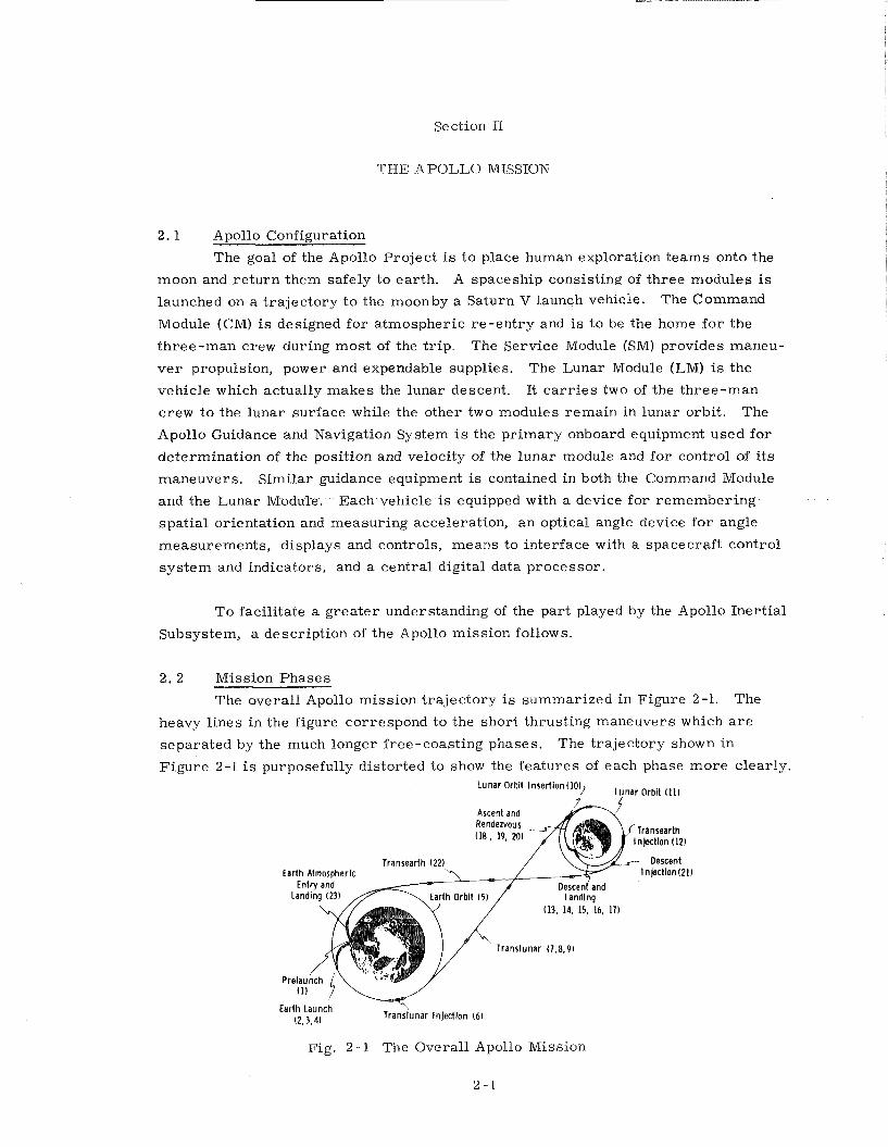
The overall Apollo mission t ra jec tory is summarized in Figure 2-1. The
heavy l ines in the figure correspond to the short thrusting maneuvers which a r e
separa ted by the much longer free-coasting phases. The t ra jec tory shown in
Figure 2-1 i s purposefully distorted to show the fea tures of each phase more clearly. Lunar Orbit InsertionIlO)/ Ljlnar Orbit
Ascent and k-J
Earth Atmospheric Entry and
Landing I231 113, 14, 15, 16, 17)
Translunar 17.8.9)
Ill
Earth Launch ( 2 , 3 . 4 ) Translunar Injection I61
Fig. 2-1 The Overall Apollo Missioil
2 -1
The numbers re la te to the rnission-phase subdivisions which are discussed in detail
in the following paragraphs.
2. 2.1 Phase l - - Prelaunch
The prelaunch phase includes a schedule of activity to prepare and verify a l l
equipment fo r flight. Automatic programmed checkout equipment is utilized to per-
f o r m exhaustive t e s t s of the major subassemblies.
Ground support equipment communicates directly with the Saturn and Apollo
CM guidance computers to read in initial conditions and mission and t ra jec tory con-
s tants a s these pa ramete r s vary a s a function of countdown status. Both s e t s of
iner t ia l guidance s e n s o r s a r e aligned t o a common vert ical and launch azimuth
framework. The ver t ica l is achieved in both cases by erection loops sensing grav-
ity. Azimuth in Saturn is measured optically f r o m the ground and controlled by
means of a n adjustable p r i sm mounted on the stable member . Azimuth in Apollo is
verified optically onboard by the astronauts and held by gyrocompassing action.
During countdown, both sys tems a r e t ied t o an ea r th f rame reference. Jus t before
liftoff, both sys tems respond to signals t o r e lease the coordinate f r ames simul-
taneously f r o m the ea r th reference t o the nonrotating inert ial reference t o be used
during boost flight. A th i rd se t of guidance equipment located in the Lunar Module
(LM) is used near t o the moon.
2. 2. 2 Phase 2 - - Ear th Launch, F i r s t Stage
During f i r s t stage flight, the Saturn guidance sys tem controls the vehicle by
swiveling the outer four rocket engines. During the initial vert ical flight, the ve - hicle is rolled f rom i t s launch azimuth t o the flight path azimuth. Following this
maneuver, the Saturn guidance sys tem controls the vehicle in an open-loop pre-
programmed pitch maneuver which is designed t o pass safely through the period of
high aerodynamic loading. Inertially-sensed accelerat ion signals a r e not used
during th is phase to guide the vehicle t o the desired flight path, but r a the r l a t e ra l
accelerometers aid in controlling the vehicle to stay within the maximum allowable
angle of attack. Stable control is achieved in overcoming the effects of flexure
bending, fuel slosh, and aerodynamic loading by the use of properly located sensors
and control networks.
Both the Saturn and Apollo Command Module guidance sys tems continuously
measure vehicle motion and compute position and velocity, In addition, the Apollo
sys tem compares the actual motion history with that t o be expected f rom the Saturn
control equations and generates an e r r o r display to the crew. This and many other
sensing and display arrangements monitor the flight. If abort c r i t e r i a a r e exceeded,
the crew can f i r e the launch escape system. This escape s y s t e n ~ consists of a
rocket on a tower attached to the top of the Command Module,which has the capability
of lifting the crew rapidly away f r o m the r e s t of the vehicle. Parachutes would be
l a t e r deployed for landing.
In a normal flight, the f i r s t s tage is allowed t o burn t o nearly complete fuel
depletion a s sensed by fuel level m e t e r s before f i r s t stage engine shutdown is
commanded.
2 . 2. 3 Phase 3 -- Earth Launch, Second Stage
Shortly af ter the initial fuel set t l ing ullage and the f ir ing of second stage
thrus t , the aerodynamic p ressure dec reases to ze ro a s the vehicle passes out of the
atmosphere. At th i s t ime the launch escape system is jettisoned. Aborts at th is
t ime, if necessary, would normally be accomplished using the Apollo Service Mod-
ule propulsion t o accelera te the Command Module away f rom the r e s t of the vehicle.
Since the problems of aerodynamic s t ructure loading a r e unimportant in
second stage flight, the Saturn guidance system s t e e r s the vehicle towards the de-
s i r e d orbital insert ion conditions using propellant-optimizing guidance equations.
Thrus t control is achieved by swiveling the outer four engines of the second stage.
During second-stage flight, the Apollo Command Module guidance sys tem
continues to compute vehicle position and velocity. Also, this sys tem computes any
of severa l other possible pa ramete r s of the flight to be displayed to the crew for
monitoring purposes. In addition, the free-fal l t ime to atmospheric ent ry and the
corresponding entry-peak accelerat ion a r e displayed to allow the crew to judge the
abor t conditions existing.
2 . 2. 4 Phase 4 - - Earth Launch, Third Stage
The third Saturn stage o r SIVB has a single engine for main propulsion which
is gimballed fo r thrust-vector control. Roll control is achieved by use of the SIVB
roll-attitude control th rus te r s .
The Saturn guidance sys tem continues to s t e e r the vehicle t o orbital altitude
and speed. When orbit is achieved, the main SIVB propulsion is shut down.
During second and third stage boost flight, the Apollo Command Module has
the capability, on astronaut option, t o take over the SIVB stage guidance function if
the Saturn guidance system indicates fai lure. If this switchover occurs, the m i s -
sion presumably could be continued. More dras t ic fai lures would require an abort
using the Service Module propulsion. In such a case, the Apollo guidance computer
would be programmed to provide a number of abort t ra jec tor ies : (1) immediate safe
r e tu rn to ear th , (2 ) r e tu rn to a designated landing site, or (3) orbit for la ter re turn
to ear th .
SIVB engine shutdown occurs about 12 minutes af ter liftoff a t 100 n. mi.
altitude near c i rcular orbit.
2. 2. 5 Phase 5 - - Ear th Orbit
The Apollo spacecraft configuration remains attached t o the Saturn SIVB
stage in ea r th orbit. The Saturn sys tem controls attitude by on-off commands to
two of the smal l fixed attitude th rus te r s for pitch and t o four more shared for yaw
and roll.
Ground tracking navigation data telemetered f rom the Manned Space Flight
Network (MSFN) station& a r e available to cor rec t the position and velocity of the
Saturn navigation sys tem and provide navigation data for the Apollo navigation
sys tem. In Apollo, the crew can a lso make navigation measurements for onboard
determination of the ephemeris by making landmark o r horizon direction sightings
using a special optical system. The Apollo inert ial equipment alignment is updated
by s t a r sightings with the same optical system. F o r these measurements the crew
has manual command-control of attitude through the Saturn system. Normally,
limited r o l l maneuvers a r e required t o provide optical system visibility to both s t a r s
and earth.
Typically, the earth-orbital phase l a s t s for severa l hours before the crew
signals the Saturn sys tem t o initiate the translunar injection.
2. 2. 6 Phase 6 -- Translunar Injection
Translunar injection is performed using a second burn of the Saturn SIVB
propulsion, preceded by a n ullage maneuver using the smal l th rus te r s . Saturn
guidance and control sys tems again provide the necessary s teer ing and thrust vec-
t o r control t o the near parabolic velocity which, for crew safety considerations,
put the vehicle on a so-called "free re turn" t ra jec tory to the moon. The sys tem
a i m s to th is t ra jec tory which ideally is constrained to pass in back of the moon and
re tu rn t o ear th-entry conditions without additional propulsion.
As before, the Apollo guidance system independently generates appropriate
pa ramete r s for display to the crew fo r monitoring purposes. If the Saturn guid-
ance sys tem indicates failure, s teering takeover by the Apollo crew i s possible
without need for aborting the mission.
2. 2, 1 Phase 1 - - T r a n s p a s i t i o ~ ~ and Docking
The spacecraft configuration injected onto the translunar free-fal l path must
be reassembled for the remaining operations.
The astronaut pilot separa tes the Command and Service Modules JCSM) f rom
the SIVB. He then tu rns the CSM around for docking t o the LM which is housed in-
side the adapter in front of the SIVB stage. To accomplish this, the pilot has a
th ree -axis, left-hand translat ional controller and a three -axis, right -hand rota-
tional controller. F o r the maneuver, output signals f rom these controllers a r e
processed t o appropriately modulate the f ir ing of the sixteen low-thrust reaction
control jets of the Service Module. The normal response f rom the translat ional con-
t r o l l e r is proportional vehicle acceleration in the indicated direction. The normal
response f rom the rotational controller is proportional vehicle angular velocity
about the indicated axis.
During the separation and turnaround maneuver of the CSM, the SIVB con-
t r o l sys tem holds the LM attitude stationary t o permit a simple docking maneuver
of the command module to the LM docking hatch. The SIVB, Saturn instrument unit
and LM adapter a r e staged t o leave the Apollo spacecraft in the t rans lunar config-
uration. Final docking is completed l e s s than 6. 5 hours f rom liftoff.
2 . 2. 8 Phase 8 -- Translunar Coast
Soon af ter injection into the translunar free-fal l coast phase, navigation
measurements a r e made and processed to examine the acceptability of the t r a j ec -
tory . If these data indicate the need, an ea r ly midcourse maneuver cor rec t s the
flight path e r r o r before it propagates with t ime into l a rge r values which would
needlessly waste correction-maneuver fuel.
Once this f i r s t correction is made - - perhaps a couple of hours f r o m injec-
t ion - - the navigation activity on board proceeds a t a more leisurely pace. Ground
tracking data can be telemetered t o the craft when available. Using these ground
data andlor onboard sextant-type landmark-to-star angle measurements, the on-
board computer co r rec t s the spacecraft s ta te vector position and velocity infor-
mation.
The astronaut navigator can examine, with the aid of the computer, each
datum input available - - whether f rom ground tracking telemetered t o the craft o r
taken onboard - - to s e e how it could change the indicated position and velocity be-
fo re it is accepted into the computer state vector correction program. In this way,
the effects of mistakes in data gathering or t ransmiss ion can be minimized.
2 , 2 , 9 Phase 9 - - Midcourse Corrections
The navigator periodically examines the computer est imate of indicated
uncertainty in position and velocity and the est imate of indicated velocity correction
required to improve the present trajectory. If the indicated position and velocity
uncertainty is suitably smal l and the indicated correction is large enough to be
worth the effort in making, then the crew prepares f o r the indicated midcourse
correction. Each midcourse velocity correction requ i res initial spacecraft orienta-
tion t o put the est imated direction of the thrus t axis along the desired accelerat ion
direction. Once thrus t direction is attained, the propulsion system is fired under
the measurement and control of the guidance system. Use of the guidance sys tem
requ i res that the iner t ia l measurement sys tem be aligned by optical star-direction
sightings.
Typical midcourse corrections a r e expected t o be of the order of 30 feet per
second. If the required correction happens to be very small , it is made by using
the smal l reaction control th rus te r s . Larger corrections a r e made with a shor t
burn of the main service propulsion engine. About th ree such midcourse velocity
correct ions a r e required on a t r i p to the moon. The direction and magnitude of
each correction adjust the t ra jec tory s o that the moon is finally approached nea r
a des i red plane and pericynthian altitude which provides for sat isfactory conditions
for the lunar orbit insertion.
2. 2.10 Phase 10 - - Lunar Orbit Insertion
F o r lunar orbit insertion, a s in a l l normal thrusting maneuvers with the
service propulsion engine, the inert ial guidance sys tem is f i r s t aligned using s t a r
sightings. Then the sys tem ganerates initial conditions and steering pa ramete r s
based upon the navigation measure of position and velocity and the requirements of
the maneuver. The guidance initiates engine turn-on, appropriately controls the
direction of the acceleration, and signals engine shut-down when the maneuver is
complete.
The lunar orbit insert ion maneuver is intended to put the spacecraft in a
near-c i rcular orbit of approximately 80 n. mi. altitude. The plane of the orbit is
selected to pass over the landing region on the front of the moon.
2. 2.11 Phase 11 - - Lunar Orbit
In lunar orbit, navigation measurements a r e made t o update the actual
orbital motion information. The navigation measurement data a r e processed in the
computer using much of the same program used in the translunar phase. Several
sources of data a r e possible. Direction measurement to lunar landmarks o r
horizons and ealth-based radio tracking telemetered data a r e si tni lar to the e e n -
surements used ea r l i e r in the flight in ear th orbit Because of the lack of lunar
atmosuhere, the t imes of selected s t a r occultations by the lunar l imb can conven-
iently be measured. Orbital period measurements a r e available by timing success-
ive passages over the same t e r r a i n feature o r successive occultations of the same
s t a r . Enough measurements must be made to provide accurate initial conditions
f o r the guidance sys tem in the LM for i t s controlled descent to the lunar surface.
Before separation of the LM, the landing a r e a is examined by the crew using the
magnifying optics in the command module. At this t ime. direction measurements
t o a part icular surface feature can re la te a desired landing s i te o r a r e a to the
existing indicated orbital ephemeris in the computer. These part icular landing
coordinates become par t of the LM guidance system initial conditions received
f r o m the command module.
After two of the crew t rans fe r to the LM and separa te f rom the Command
and Service Module (CSM), the remaining man in the CSM continues orbital navi-
gation a s necessary t o maintain a n accurate knowledge of the CSM position and
velocity.
2. 2.12 Phase 12 - - LM Descent Orbital Insertion
The LM guidance sys tem is turned on and checked out ea r l i e r in lunar orbit
before separation and before initial conditions a r e received f rom the CSM. About
twenty minutes before initiation of the LM descent injection maneuver, the vehicles
a r e separated, the LM guidance sys tem receives final alignment f rom s t a r sightings,
and the attitude f o r the maneuver is assumed. The maneuver i s made using the LM
descent stage propulsion under control of the LM guidance system. The throttling
capability of the descent engine is exercised a s a check of i t s operation during the
shor t burn. The maneuver is a 100 ft. per second velocity change to reduce the
5250 ft. per second orbital velocity for a near-Hohmann t r ans fe r to 8 n. mi. altitude
pericynthian which is t imed t o occur at a range of about 200 n. mi. shor t of the
final landing area .
2. 2.13 Phase 13 - - LM Descent Orbit Coast
During the free-fal l phases of the LM descent, the CSM can make tracking
measurements of the LM direction to confirm the LM orbit with respect to the CM.
F o r that part of the t ra jec tory in the front of the moon, ea r th tracking provides an
independent check. The LM, during appropriate intervals in the coasting orbit,
checks the operation of i t s r ada r equipment. The directional tracking and ranging
operation of the rendezvous r a d a r is checked against the radar transponder on the
CSM. These data provide the L M computer with added information for a descent
orbit check. A t lower a l t i tudes , the L M landing radar on the descent stage is oper-
ated for checks using the moon surface re turn . Alignment updating of the LM
guidance system is performed i f desired. The CM from i t s orbit, using the tracking
sys tems and onboard computer, can monitor this phase of the LM descent. As
pericynthian i s approached, the correct LM attitude for the powered descent phase
i s achieved by signals f rom the guidance system.
2. 2.14 Phase 14 - - LM Powered Descent Braking Phase
This phase s t a r t s at the 8 n. mi. altitude pericynthian of the descent coast
phase. The descent engine is reignited, and the velocity and altitude-reducing
maneuver is controlled by the LM inert ial guidance and control system.
The descent stage engine is capable of thrust level throttling over the range
necessary t o provide initial braking and controlled hover above the lunar surface.
Engine throttle set t ing is commanded by the guidance and control sys tem t o achieve
proper path control, although the pilot can override th is signal if desired.
Thrust vector direction control of the descent stage i s achieved by a combin-
ation of body-fixed reaction jets and limited gimballing of the engine. The engine
gimbal angles follow guidance commands in a slow loop s o a s t o cause the thrust
direction t o pass through the vehicle center of gravity, thus minimizing ihe need
fo r continuous fuel-wasting torques f rom the reaction jets. During a l l phases of the
descent, the operations of the various sys tems a r e monitored. The mission could
be aborted for a number of reasons. If the p r imary guidance and control system
performing the descent control is st i l l operating satisfactorily, i t would control the
abort back t o rendezvous with the CSM. If the p r imary sys tem has failed, a simple
independent abort guidance sys tem can s t e e r the vehicle back to conditions for ren-
dezvous. F o r a normal mission, however, the braking phase continues until the
altitude drops to about 4 n. mi. Then guidance control and t ra jec tory enter the final
approach operation.
2. 2.15 Phase 15 - - LM Powered Descent Final Approach
One significant feature of this phase i s that the controlled t ra jec tory i s se-
lected t o provide visibility of the landing a r e a to the LM crew. The vehicle attitude,
descent ra te , and direction of flight a r e controlled by the guidance s o that the land-
ing si te appears fixed with relat ion to the window. A simple ret icle pattern in the
window gives anindication of whether the landing point is aligned with the number
indicated by the computer display. The pilot may observe that the landing point indi-
cated, with relat ion t o other a r e a s nearby, is in an a r e a of unsatisfactory features.
The pilot can then elect to select a new landing point fo r the computer control by
turning the vehicle about the thrus t axis until the ret icle in tersects the better
area . He then hits a "mark" button to signal the computer, r eads the re t ic le
riurnber which is i n l ine with th is a r e a into the computer and then the guidance
sys tem appropriately red i rec t s the path. This capability allows ea r ly change of
landing a r e a and efficient fuel control during acquisition of the new a r e a which
otherwise might have to be performed wastefully l a t e r during hover.
Automatic guidance control during the terminal phase uses weighted combin-
at ions of inert ial sensing and landing radar data. The weighting depends upon
expected uncertainties i n the measurements. The landing r a d a r includes altitude
measurement and a three-beam Doppler measurement of three components of L M
velocity with respect t o the lunar surface.
2. 2.16 Phase 16 - - Landing and Touchdown
At any point in the landing, the pilot can elect to take over par t ia l o r com-
plete control of the vehicle. F o r instance, one logical mixed mode would have
altitude descent r a t e controlled automatically by modulation of the thrus t magni-
tude and pilot manual control of attitude for maneuvering horizontally.
The final approach phase ends near the lunar surface, and the spacecraft
en te r s a hover phase. Th i s phase can have various possibilities of initial altitude
and forward velocity depending upon mission ground ru les , pilot option and observed
l o c a l t e r r a i n f e a t u r e s . D e s c e n t s t a g e f u e l a l l ~ ~ a n ~ e p r o v i d e s f o r a p p r o x -
imately two minutes of hover before touchdown. This must be accomplished in the
t ime allotted o r abort on the ascent stage is initiated. The crew will make final
selection of the landing point and maneuver t o it ei ther by tilting the vehicle o r by
operating the reaction jets for translat ion acceleration. Inasmuch a s the flying
dust and debr is result ing f rom rocket exhaust degrades radar and visual information,
the inert ial sys tem altitude and velocity computation is updated by the landing radar
s o that, a s touchdown is approached, good data a r e available f rom the inert ial sen-
s o r s . Touchdown must be made with the craft near ver t ica l and a t sufficiently low
velocity.
2. 2.17 Phase 17 - - Lunar Surface Operations
Time spent on the moon includes considerable exploration, experimentation
and gathering of soi l samples. Also, during the s tay time, the LM spacecraft sys -
t e m s a r e checked and prepared fo r the re tu rn voyage. The ephemeris of the CSM
i n orbit is continually updated and the information relayed t o the LM crew and
computer. The LM rendezvous r a d a r a lso can t r a c k the CSM a s it passes overhead
to provide further data upon which t o base the ascent guidance pa ramete r s . The
inert ial guidance sys tem receives final alignment utilizing optical star-direction
sightings prior t o the s t a r t of ascent. The vert ical components of th is alignment
could a lso be achieved by accelerometer sensing of lunar gravity in a vert ical e r e c -
tion loop. 1,iftoff is t imed t o achieve the desired t ra jec tory for rendezvous with the
CSM.
2. 2.10 Phase 18 - - LM Ascent
LM powered ascent is accomplished with the LM ascent engine. The ascent
engine, which h a s a fixed mounted nozzle, is under control of the LM inert ial
guidance and control system. Thrust vector is achieved by operation of the sixteen
reaction jets that a r e mounted on the ascent stage. The engine cannot be throttled,
but the necessary signals f rom guidance w i l l te rminate the burning when a suitable
t ra jec tory is achieved.
The initial par t of the ascent t ra jec tory is a vert ical r i s e followed by a pitch-
over a s commanded by the guidance equations. During the pitchover maneuver, the
guidance system a l so commands ro l l s teer ing such that the LM maneuvers into an
elliptical orbit coplanar with the CSM plane.
2.2.19 Phase 19 - - LM Midcourse Maneuvers
A constant delta height maneuver is initiated a t the apocynthion of the LM
concentric elliptical orbit that places the LM in a c i rcular orbit which is predeter-
mined such that the LM a r r i v e s a t a required position with respect to the CSM a t
the terminal phase initiation t ime. During th is phase, the crew verif ies LM t ra jec -
to ry pa ramete r s a s computed by the LM guidance computer with the parameters
computed by the command module computer.
2. 2. 20 Phase 20 -- Terminal Rendezvous and Docking
The terminal rendezvous phase consists of a s e r i e s of braking thrus t maneu-
v e r s under control of the LM guidance system which uses data f rom i t s inert ial
sensors and the rendezvous radar . The objective of these operations is to reduce
the velocity of the LM relat ive to the CSM to ze ro a t a point near the CSM. This
leaves the pilot in the LM in a position to initiate a manual docking maneuver with
the CSM using the translat ion and rotation control of the LM reaction jets. Although
these maneuvers would normally be done with the LM, propulsion o r control prob-
l e m s in the LM could require the CSM to take the active role.
After final docking, the LMcr'ew t r a n s f e r s t o the CSM. The LM is then
jettisoned and abandoned,
2. 2. 21 Phase 21 - - Transea r th Injection
Navigation measurements made while in lunar orbit determine the proper
initial eon~ditions for t ransear th injection, These a r e performed a s before using
onboard and ground -based t r a e king data as available.
The guided t ransear th injection maneuver is made normally under the ccn-
t r o l of the p r imary inert ial guidance system. Several backup means a r e available
t o cover possible fa i lures in the pr imary system. The injection maneuver is con-
trolled to put the spacecraft on a f r ee -fall coast to sat isfactory ent ry conditions
near earth. The t ime of midcourse t ransear th coast must be adjusted by th is in-
jection maneuver t o account for ea r th ' s rotation motion of the recovery a r e a and a s
l imited by the ent ry maneuver capability.
2 . 2 . 2 2 Phase 22 -- Transea r th Coast
The t ransear th coast is very s imi lar t o the t rans lunar coast phase.: During
the long coasting phases going t o and f rom the moon, the sys tems and crew must
control the spacecraft orientation a s required. Typical midcourse orientation con-
s t r a in t s a r e those necessary t o a s s u r e that the high-gain communication antenna is
within its gimbal l imi ts to point to earth, o r that the spacecraft attitude is not held
fixed t o the local heating effect of the sun fo r too long a period.
During the long periods of f ree -fall flight to and f rom the moon, when the inert ial
measurement sys tem is not being used for controlling velocity corrections, the inert ial
sys tem is turned off to conserve power supply energy.
Onboard and ground-based measurements provide for navigation upon which
is based a s e r i e s (normally three) of midcourse correction maneuvers during t r a n s -
ea r th flight. The aim point of these corrections i s the center of the safe ea r th
ent ry corr idor suitable for the desired landing a rea . This safe corr idor is ex-
pressed a s a variation of approximately rt17 n. mi. in the vacuum perigee. A too-
high ent ry might lead t o an uncontrolled skip out of the atmosphere. A too-low
entry might lead t o atmospheric drag accelerat ions exceeding the tolerance of the
crew.
After final safe entry conditions a r e confirmed by the navigation sys tem
pr io r to the en t ry phase, the inert ial guidance sys tem is aligned, the Service Mod-
ule is jettisoned and the initial entry attitude of the Command Module is attained.
2. 2. 23 Phase 2 3 - - Earth Atmospheric Entry
Initial control of ent ry attitudes is achieved by guidance system commands
t o the twelve reaction jets on the command module surface. As the atmosphere is
entered, aerodynamic fo rces create torques determined by the shape of the CM and
center-of-mass location. If initial orientation was correct , these torques a r e in a
direction towards a. stable t r i m orientation with heat shield forward and flight path
nearly parallel to one edge of the conical surface. The control system now oper-
a t e s the reaction jets to damp out oscillation about th is t r i m orientation. The
result ing angle of at tack of the ent ry shape causes an aerodynamic lift force which
can be used fo r entry path control by rolling the vehicle about the wind axis under
control of the guidance system. Range control is achieved by rolling s o that an ap-
propriate component of that lift is ei ther up o r down a s required. Track o r a c r o s s
range control is achieved by al ternately choosing a s required the side on which the
horizontal lift component appears.
The ea r ly par t of the ent ry guidance is concerned with the safe reduction of
the high velocity through the energy dissipation effect of d r a g forces . Later , a t
lower velocity, the objective of controlling the vehicle t o the ea r th recovery landing
a r e a is included in the guidance programming. This control continues until the ve-
locity is reduced and a suitable position is achieved for the deployment of a drogue
parachute. Final letdown t o a water landing is normally achieved by three para-
chutes.
Section I11
THE APOLLO INERTIAL SUBSYSTEM, AN OI'ERVIEW
3 . 1 Early Decisions --Block I
During 1957 through 1959, MIT/IL performed a study which led to the publi-
cation of a repor t in June of 1959 entitled "Recoverable Interplanetary Space Probe. "
In September 1959, under a NASA contract, MIT/IL undertook a study of the
guidance and control design for a variety of space missions. The study report was
issued in April 1960 and showed the onboard sensor capability which could support
Navigation and Guidance for manned o r unmanned spacecraft, Jh r ing this period,
NASA was defining i t s advanced manned space flight program which would follow
Mercury and Gemini and which was named "Apollo" in July of 1960 by the NASA
Administrator. The program was to lead, eventually, to a manned lunar landing.
In November 1960, a six-month contract with MIT to conduct preliminary
design work for the navigation and guidance support for project Apollo was
proposed by NASA. The manned lunar landing was made a national goal by
President Kennedy in May 1961. In August of 1961, NASA awarded i t s
f i r s t major Apollo contract to MIT/IL to develop the guidance and navigation system.
It is important a t the outset to understand the factors governing the design of the
Apollo G&N in i t s initial phases. In late 196 1, plans were to fly an Apollo space-
craf t in the fall of 1963 with an MIT G&N system on board. The NASA direction
to support th is schedule was to (a ) build that which we knew how to build in the time
allotted, and (b) to use only components proven by production and operational
experience.
Numerous fundamental and f a r reaching decisions were made quickly in the
ear ly days of the contract. The IMU gimbal question was one of the most funda-
mental. It was reasoned that IMU in-flight alignment would be a necessity. No
gyro would be able to maintain adequate inert ial reference for a period of twelve
days to cover a l l the necessary maneuvers. With a realignment concept and
recognition that a l l maneuvers where the IMU was required were in-plane maneuvers
with little o r no out-of-plane steering, it was reasoned that a 3 gimbal sys tem could
be used. This had several advantages over a 4 gimbal IMU in t e rms of system
complexity, weight, power, reliability and cost.
3. 1. 1 Gimbal System Arrangement
Although a strapdown or body-mounted inert ial subsystem configuration was
briefly examined a t the s t a r t of the program, no ser ious consideration was given
to this technrque. The smal l development time that the schedule allowed and the
fact that no such body-mounted system was yet out of the laboratory experimental
stage precluded its use. Moreover, i t was c lea r that schedules could be met by
the existing development t eam by utilizing past experience with the design of the
gimballed iner t ia l measurement unit of the Polar is Mark 2 guidance system.
At the time the decision was made in 1961, there appeared to be no doubt
that a three degree-of-freedom gimbal sys tem would be the optimum choice for the
inert ial measurement unit. To simplify hardware design, the various ground rules
mentioned e a r l i e r emphasized simplicity, light weight, optimum performance and
utilization of crew capability. These ground rules a l l indicated that,for the Apollo
mission, a three degree-of-freedom gimbal arrangement was to be preferred over
the four degree-of-freedom configuration.
The function of the gimbal sys tem arrangement was to support the gyros
and accelerometers on a structure that would be kept nonrotating in space in spite
of rotations of the spacecraft . The only motivation for a four degree-of-freedom
gimbal sys tem was that such a configuration could be made and operated so that
a l l attitudes of the spacecraft would be accommodated without the problem associated
with gimbal lock that could possibly occur with a three degree-of-freedom system.
The question posed in 1961 and 1962 was: Could the simpler three degree-of- freedom
IMU meet a l l the requirements Apollo would ask of i t without danger of approaching.
gimbal lock and loss of stable member alignment? The answer in brief was that
a l l usual Apollo maneuvers would naturally be such that gimbal lock would be
avoidable by a sufficiently wide margin to be easily accommodated by the three
degree-of-freedom candidate IMU under consideration. In unusual situations the
operation n e a r gimbal lock in nonemergency maneuvers could be simply avoided.
Direct means were available to warn of approaching difficulty so that corrective
action could be taken. And finally, the procedure for recovery f rom loss of
alignment, if i t occurred--even in emergency situations--seemed straightforward.
The discussions that were relevant to IMU selection a r e included in the following
sections.
3 . 1. 2 Per.tinent IMU Design Characterist ics
The IMU design under consideration borrowed heavily f rom .that of .the
Polar is Mark 2. The capability of this c lass of design to maintain s-table member
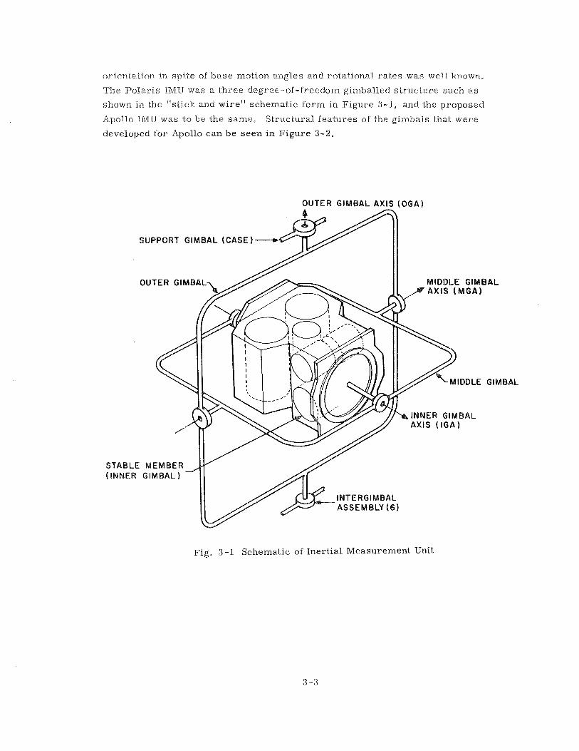
ori.enta.tion in spite of base motion angles and rotati-onal r a t es was well known,
The Polar is IMU was a three degree-of-freedom gimballed s t ructure such a s
shown in the "stick and wire" schematic form in Figure 3-1, and the proposed
Apolio IMU was -to be the same, Struc-tural features of the gimbals that were
developed for Apollo can be seen in Figure 3 - 2 ,
OUTER G I M B A L AXIS ( O G A l
Fig. 3 -1 Schematic of Inertial Measurement Unit
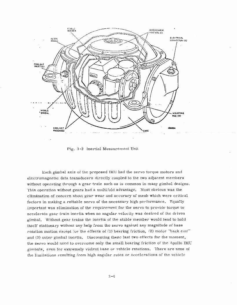
Each gimbal axis of the proposed IMU had the servo torque motors and
electromagnetic data transducers directly coupled to the two adjacent members
without operating through a gear train such a s IS common in many gimbal designs.
This operation without gears had a multifold advantage. Most obvious was the
elimination of concern about gear wear and accuracy of mesh which were cr i t ica l
factors in making a reliable servo of the necessary high performance. Equally
important was elimination of the requirement for the servo to provide torque to
accelerate gear t r a in inert ia when no angular velocity was desired of the driven
gimbal. Without gear t ra ins the inert ia of the stable member would tend to hold
itself stationary without any help f rom the servo against any magnitude of base
rotation motion except for the effects of (1) bearing friction, (2) motor "back emf"
and ( 3 ) outer gimbal inertia. Discounting these last two effects for the moment,
the se rvo would need to overcome only the smal l bearing friction of the Apollo IMU
gimbals, even for extremely violent b a s e o r vehicle rotations. There a r e none of
the limitations resulting from high angular ra tes o r accelerations of the vehicle
imposed by the usual gimbal axis gear t ra ins .
The second effect mentioned above, back emf, concerns the voltage
generator actlon of the motor, the servo amplifier drlve ~mpedance, a correspond~ng
lag t e r m in the servo loop, and a base motion coupling. The level of the output
current feedback under consideration in the Apollo IMU se rvo would control these
effects adequately so that any concern of base motion angular velocity coupling a s
a result of motor voltage would be trivial within any conceivable uncontrolled
vehicle maneuvers f rom which recovery is possible.
The third effect, resulting f rom outer gimbal inertia, comes into play only
with large middle gimbal angles away f rom the ze ro orientation. See Figure 3-1.
In the extreme situation, large middle gimbal angles cause the effect called
"gimbal" lock. This subject i s s o extensive that the ensuing section has been
devoted to its exposition.
3 . 1 . 2 . 1 The Problem of Gimbal Lock. Gimbal lock occurs when the outer gimbal
axis is ca r r i ed around by vehicle motion to be parallel to the inner gimbal axis.
At this point the three gimbal axes l ie in a single plane. No gimbal freedom now
exists to "unwind" base motion about an axis normal to this plane. Even though
any vehicle orientation with respect to the stable member can be accommodated by
part icular se t s of the three gimbal angles, the condition a t gimbal lock prevents
accommodation of a part icular orientation change from the locked condition without
exceedingly high outer gimbal acceleration.
Problems with a three degree-of-freedom system like the Apollo IMU
which was being considered could occur under circumstances other than the gimbal
locked situation. For instance, when the locked configuration i s approached, a s
manifested when middle gimbal angles approach go0, the stabilization capabilities
of the assembly become more and more marginal depending on design. With
proper gyro e r r o r signal resolution and gain control, the locked configuration can
be very closely approached without undesirable effects. However, a s gimbal lock
i s approached more closely, higher and higher angular accelerations a r e required
of the outer gimbal to hold the inner member fixed against part icular components
of base angular velocity. By an inherent tendency to stay fixed, the inert ias of the
inner gimbals can generate much of the necessary reaction torque to help provide
the required acceleration of the outer gimbal over a limited range. This would be
perfect without the accelerating torque from the outer servo motor i P ei ther the
inner s t ructures were of infinite inert ia o r the outer structure were zero inertia.
Lacking an infinite rat io of the two, the remaining burden of providing the accel-
erating torclue must be taken by the servo and outer gimbal motor.
In Apollo, the outer gimbal s t ructure achieved necessary s t ructura l sliIf-
ness through the thin section spherical shape with a relatively smal l inertia. The
inner stable member ca r r i ed a l l the m a s s of the inertial components and necessary
thermal sink mounting block.
Besides favorable inert ia rat ios, much of the capability of the Apollo IMU
to handle near gimbal lock conditions was at f i r s t attributed to the use of a smal l
angular accelerometer on each axis (ADA) a s a servo stabilization feedback
element. This device permits very high torque gains with low servo noise problems
over a l l frequencies and allows specification operation over a wide margin of gain
change. No cr i t ica l adjustments a r e necessary. The Block I IMU utilized this ADA
a s the high frequency feedback device with good success. Later in the studies for
the Block I1 IMU, the gyro noise inserted into the loop resulting f rom the necessary
high frequency gain was found tolerable and the ADA was eliminated.
Moreover, i t was argued that transient loss of attitude resulting f rom
gimbal lock effects, o r any other disturbance fo r that mat ter , did not necessari ly
mean a permanent loss of orientation indication of the IMU, unless the gyro gimbal
output axis limit stops were reached. Within the integration range of the gyro, the
attitude i s recovered a s the gyro e r r o r is brought back to zero. In effect, the
orientation is memorized in the gyro output axis angle and angular velocity until
the se rvo can recover.
F i r m ground rules on how close to gimbal lock the Apollo IMU could operate
satisfactorily depended upon experimental resul ts with the actual flight configuration
IMU. Data, using IMU #3 with breadboard electronics, were collected From this
information, it appeared that gimbal lock could be approached a s closely a s 10
degrees without r i sk and even much c loser with some possibility of loss of stable
member attitude. Stated more graphically, a test was conducted where the Inner
axis of the sys tem was aligned within 10 degrees of a base motion axis perpen-
dicular to the output axis. Base motion angular velocity then caused gimbal lock
to be passed within 10 degrees. Stable member attitude was held consistently for
this configuration with base angular velocities of 60 degrees per second. A tentative
and conservative listing of acceptable vehicle ra tes and accelerations was then
generated:
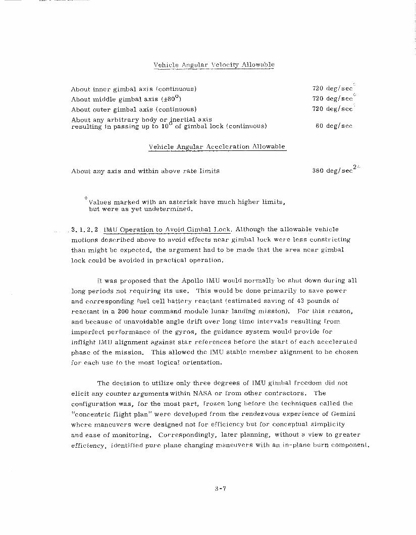
Vehicle Angular Velocity Allowable
About inner gimbal axis (continuous)
About middle gimbal axis (f80°)
Abowt outer gimbal a-xis (continuous)
About any a rb i t ra ry body o r Jnertial axis resulting in passing up to 10 of gimbal lock (continuous)
Vehicle Angular Acceleration Allowable
About any axis and within above ra te limits
' Values marked with an as ter isk have much higher l imits, but were a s yet undetermined.
3. 1.2.2 IMU Operation t o Avoid Gimbal Lock. Although the allowable vehicle
motions described above to avoid effects near gimbal lock were l e s s constricting
than might be expected, the argument had to be made that the a rea near gimbal
lock could be avoided in practical operation.
It was proposed that the Apollo IMU would normally be shut down during a l l
long periods not requiring i t s use. This would be done primarily to save power
and corresponding fuel cell battery reactant (estimated saving of 43 pounds of
reactant in a 200 hour command module lunar landing mission). For this reason,
and because of unavoidable angle drift over long time intervals resulting f rom
imperfect performance of the gyros, the guidance sys tem would provide for
inflight IMU alignment against s t a r references before the s t a r t of each accelerated
phase of the mission. This allowed the IMU stable member alignment to be chosen
for each use to the most logical orientation.
The decision to utilize only three degrees of IMU gimbal freedom did not
elicit any counter arguments within NASA o r f rom other contractors. The
configuration was, for the most part , frozen long before the techniques called the
"concentric flight plan" were developed f rom the rendezvous experience of Gemini
where maneuvers were designed not for efficiency but for conceptual simplicity
and ease of monitoring. Correspondingly, la ter planning, without a view to g rea te r
efficiency, identified pure plane changing maneuvers with an in-plane burn component.
Thus, the possibility of exactly out-of-plane burns became f a r more probable than
was thought ea r l i e r to be the case.
Currently, the out-of-plane burns during rendezvous a r e accomplished with
the RCS thrusters in a low acceleration translation. In th is way, the vehicle can be
accelerated sideways without changing spacecraft orientation to gimbal lock
attitudes. This method a l so allowed for a maneuver which did not break r a d a r lock
o r astronaut line of sight on the CSM. Avoidance of any gimbal lock problem during
the actual thrusting and entry phases of Apollo offers no difficulty.
For the majori ty of mission aborts, the TMU gimbal lock situation was seen
to put no more constraint on successful abort than on normal mission phases. Two
mission phases were identified, however, which would require cr i t ica l dependence
upon the IMU indicated attitude to cope successfully with the emergency. The f i r s t
of these was high altitude abort pr ior to launch escape tower jettison. If the
command module tumbles during this operation there is a possibility that the
outer axis might pass through the cr i t ica l a r e a s near gimbal lock causing the loss
of IMU attitude information, If co r rec t entry attitude is not assumed ear ly enough,
the reaction jets might not be able to overcome and cor rec t the improper but stable
attitude of having the conical end point forward a s contrasted with the proper blunt
end forward entry orientation. In view of the ra te limitations of the backup
attitude sys tem and the problems of getting attitude cues through the windows,
dependency on IMU attitude information might be necessary. The probability
of exceeding crew s t r e s s l imi ts by a conical end forward entry in the situation
described is the product of: (1) the probability that abort is initiated at the
cr i t ica l altitude, ( 2 ) the probability that the abort initiates an uncontrolled tumble,
( 3 ) the probability that the tumble causes the IMU to pass through i t s cr i t ica l gim-
bal lock a reas , and (4) the probability that the pilot cannot sense the direction of
drag ear ly enough to cor rec t attitude o r that the command module enters conical
end f i rs t . It was conjectured but not proven that the resulting probability was an
extremely smal l number.
The second mission phase, which was identified a s being cri t ical with
respect to IMU gimbal lock limttations, was during the LM lunar landing. A hard
over LM descent engine gimbal failure in .the yaw direction would require positive
pilot action almos-t immediately to avoid gimbal lock. F r o m a vertical hover
orientation, a random tumble f rom -the vert ical has an 11q chance of passing within
10 degrees of the lock orientation i f not s-topped before 90 degrees. If the a.ttitude
information was lost by such a maneuver, the vehicle would be thrusting nearly
horizontally and probably downward unless the engine was immediately shut down
which, of course, would be the proper f i rs t action during this emergency.
3 , l . 3 Considerations of a Four Degree-of-Freedom IMU
Difficulties near gimbal lock can be avoided by -the addition of a fourth
gimbal to the IMU. This additional gimbal is called the redundant gimbal since i t
provides more degrees of freedom than theoretically necessary on a geometric bas is .
This redundant gimbal, i f used, would have been mounted outside the normal outer
gimbal. The order would have been: inner, middle, outer, and redundant. See
Figure 3-3. The most likely operation would use the inner -three gimbals to drive
the stabilizing gyro e r r o r signals .to ze ro while the fourth gimbal would be driven so
a s .to keep the middle gimbal n e a r ze ro and away f rom -the gimbal lock orientation.
This could be done by generating a redundant gimbal ra te command by expressions
s imi la r t o
- sin A(middle) A(redundan.t) - -A cos (outer)
s o that a negative feedback occurs t o drive the middle angle towards zero. ' I t
should be possible to make the inner three gimbals have the same dynamic per-
formance a s the simpler three degree-of-freedom system. Any base motion
coupling, though, avoided in the Apollo sys tem a s described ear l ier , would make
redundant gimbal motions appear a s disturbances on the middle o r inner servos,
thus requiring special attention in loop responses. The redundant gimbal must be
accelerated i f i t is t o do its job, even when the middle gimbal angle i s near zero.
In fact, a situation like gimbal lock occurs for outer angles near 90 degrees a s can
be seen in the above equation. Close to 90 degrees outer gimbal angle, the
redundant gimbal must be driven a t a very fast ra te to hold the middle gimbal
angle a t zero. In practice, this offers no r e a l difficulty a s long a s the vehicle body
ra tes a r e within cer ta in l imits.
With .the four degree-of-freedom gimbal system, there a r e no cons-traints
on vehicle attitude although r a t e l imi ts do s t i l l exist for certain paths of attitude
motion.
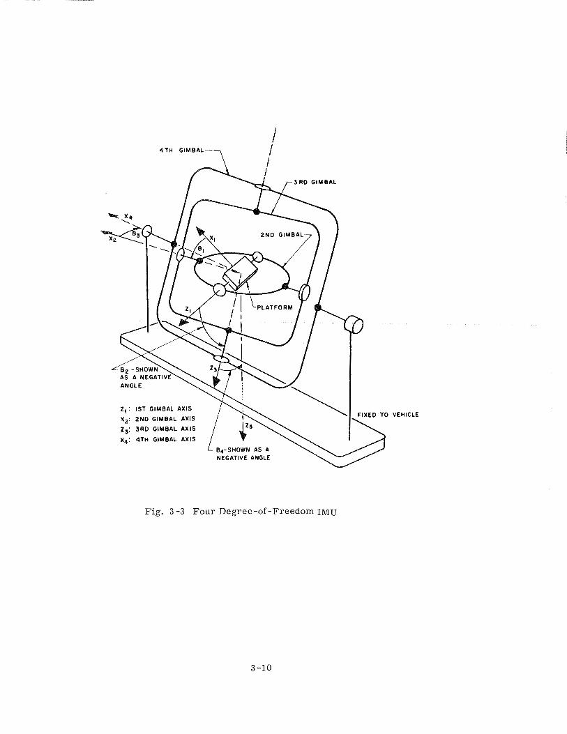
VEHICLE
Fig. 3 -3 Four Degree-of -Freedom IMU
The disadvantages of using a four degree-of-freedom IMU were considered
significant. To execute the fourth gimbal would have required an extra servo
different from the other three servos in dynamic design. Extra data transducers,
o r the equivalent, on the middle and outer axes to determine the redundant glmbai
commands would have also been required.
The expense involved in having to add .the fourth gimbal depended upon a
number of factors. In order .to achieve -the required guidance sys tem performance
demanded of -the lunar mission, .the desired lMU alignment accuracy s.tood out as a
cr i t ica l design factor. This meant gimbal data transducers having peak e r r o r s no
worse -than 20 seconds of a r c would be required in o rder t o use -the optics sys tem
for s t a r alignment references. The addi-tion of a fourth gimbal .to achieve the
alignment would have compounded the problem in .the IMU structure, in .the computer
interface, and in -the flight computer program.
At the time, the 20 a r c second accuracy data transducers determined the
s ize of the Apollo IMU. Without these large units the IMU would have been severa l
inches smal le r i n diameter. It was est imated that a fourth gimbal using these s a m e
proven transducers would have ra ised IMU st ructure weight by 15 pounds and
increased the volume by 725 cubic inches.
The Polar is advanced guidance sys tem in a four degree-of-freedom con-
figura-tion was estimated to weigh only 213 the Apollo three degree-of-freedom uni-t
and would have had equivalent performance except for the accuracy of the axis da-ta
transducers. Advances in smal l accurate data t ransducers were being studied wi-th
-the goal of direct digital encoding of gimbal angles. This could have led to simpli-
fication of the CDUts,but the interface wtth the existing "eight ball" attitude display
would have been much m o r e difficult.
Additional complexity would have resulted in making full use of a four
degree-of-freedom system. An additional CDU ( 3 pounds plus electronics for
Block I hardware) would be required for flexible operation with the computer. The
additional gimbal would have required a longer resolution chain to generate autopilot
attitude e r r o r for pilot display. This chain was already difficult to achieve under
the requirements imposed by the existing autopilot interface. Also, the computer
would have had t o assume the burden of providing the r e a l t ime resolutions required
t o convert s teer ing angles in accelerometer coordinates into proper CDU commands.
Although this was done anyway in the more capable Block I1 flight computer, i t was
not realist ic to do s o in the Block I computer.

The addition of a fourth gimbal, other things belng equal, would necessarrly
have increased the power drain on the main fuel cell batteries, besides having
required an extra se t of servo electronics. Heat transfer f rom the gyros inside
to the heat sink on the housing would have been made much more difficult by the
addition of the fourth gimbal. The redundant axis would have had to have sl ip r ings
to be useful and would have had to c a r r y a l l s ignals on the outer axis r ings plus
those of the redundan.t axis instrumentation.
One problem considered was generating three degree-of-freedom a-ttitude
ball commands f rom a redundant four degree-of-freedom IMU. This could have
been solved by the development of a compatible four degree-of-freedom ball, but
.the s ize penalty on the panel would have been prohibi-tive. The electrical resolution
conversion f rom four degrees of freedom .to -the necessary -three degrees becomes
bound up in .the equivalence of gimbal lock for which .the redundant gimbal was .to
have prevented. Although the four degree-of-freedom IMU avoids gimbal lock and
loss of attitude, the attitude information is difficult -to display.
The advantages of the redundant gimbal seemed to have been outweighed by
equipment simplicity, s ize advantages, and corresponding implied hardware
reliability of the direct th ree degree-of-freedom unit. Since no operational
difficulty of significance could be imagined with the three degree-of -freedom gimbal
system, the decision to avoid the fourth gimbal was made.
In retrospect , some hesitation about the wisdom of the decision might b e
expressed. As stated ear l ier , the orbital operations during rendezvous with the
"concentric flight plan" made the probability of desired orientations near gimbal
lock much higher than the more efficient direct rendezvous originally envisioned
where needed orbital plane changes were combined with the needed in-plane transfer
orbit burns. There is no doubt that with present technology, a four degree-of-freedom
all-attitude IMU could be produced with no m o r e total weight, volume, power, o r
failure r a t e than the present three degree-of-freedom unit of 1964 vintage. But for
that mat ter , the three degree-of-freedom unit would also correspondingly benefit
f rom present technology.
3.1 . 4 Component Section
3. 1.4. 1 Gyroscopes. The f i r s t step in selecting a gyro was to perform an e r r o r
analysis of the e .qec ted -trajectories to determine .the criticali-ty of performance.
Wkth .the realignment capability and with position e r r o r s for landing of l e s s than 10
t nautical miles, a 1 0 meru gyro appeared feasible. Several candidate gyros were
considered. A modification of the type of gyro used for Polar is was chosen for the
Apollo application. The production records were impressive and i t s performance
was satisfactory. Moreover, the designers were familiar with the instrument.
A decision was made to have separate NASA inert ial component procurement and
to have only one source for each component. The flight schedule was somewhat
uncertain, however, and i t was decided to allow a s much time a s possible for that
contingency. The expected wheel hours in operation were to be about 2000 for ear ly
flight sys tems and about 1200 for la ter flights. This assumption has since been
proven too low by a factor of about 50%.
Some design changes were made to -the gyro which made it different f rom
the Polar is instrument. The torque generator was changed f rom a two winding
current product .torque -to a single winding curren-t squared -torque. This was done
to provide -the mos t efficient interface be-tween the computer and the IMU, principally
fo r alignment. The suspension frequency and signal generator frequency were
changed f r o m 4800 Hz and 800 Hz, respectively, to 3200 Hz. The change was dictated by the available computer timing pulses. 6400 HZ could have been
selected but experience with higher frequencies was lacking.
To assure a quali-ty gyro, acceptance specifica-tions were tightened, and a
reliability program was s tar ted which would provide reliability data and failure
prediction methods applicable to production line gyros.
3. 1.4. 2 Accelerometers. The accelerometer selected was a modified Polar is
16 PIP. This selection was based pr imari ly upon the simplicity of the P I P over the
16 PIGA (the other possible MIT/IL choice) and the inherent reliability believed
possible. The performance requirements were not extensive, but were difficupt
f o r the PIPA to fulfill. Apollo asked for about 100 par ts per million accuracy and an
acceleration range of f 16 g. The knowledge of torque generators and electronics being
what i t was dictated the choice of reducing the pendulosity f rom 1 grn c m to 114 gm cm,
which had the obvious effect of magnifying bias ins-tability. To achieve bet ter
scale factor stability, .the tapered suspension was added to the design. A significant
number of design changes were incorporated throughout the l i fe of the program.
' 1 meru i s a Milliearth Rate Unit equal to 0 . 0 15 degree per hour.
The initial conception for the accelerometer was that of a ternary or three
state torqued accelerometer because the computer would not be able to handle the
limit cycle operation of a binary f3 A V pulse-input. It was further decided to have
a three scale factor accelerometer, A nominal scale factor with a capability of
about 16 g t s was the primary mode. There was to be a low g capability where the
A V scaling was to be decreased by a factor of four. This was primarily done to
abet performance during the early phases of entry, particularly during the skip
out portion. In the event of a steep entry provision, the accelerometer was
subjected to the maximum acceleration capability by reverting it to a binary mode
that increased the A V by a factor of approximately 2 . These decisions, in view
of the fact that many requirements were then unknown, represented the best
engineering judgment available. Later, the accelerometer was changed to a
binary torqued single scale factor device which permitted considerable system
simplification.
3. 1.4.3 Component Data Management. Both inertial components were to have
common test equipment at the factory of the inertial component manufacturer, MIT
and the Inertial Subsystem contractor. This communality of test equipment was in
line with maintaining transfer of inertial performance from location to location.
MIT thus maintained configuration control over both the PIP and IRIG test
consoles. In the case of the gyro test console, the design work of the analog equip-
ment was done by AC Electronics, and MIT designed the digital portion. MIT
designed the final test consoles for the 16 PIP Mod D.
lt was decided early in the program .that MIT would maintain inertial
performance parameters for a l l components. This early decision and its
execution se t up the now existing gyro and PIP performance parameter -tabulation
and distribution system. Initially, MIT set up .the system and maintained records.
Later, Dynamics Research was brought in to do .the job which had grown considerably.
The possibility now existed for comparing the Apollo gyro with .the very similar
Polaris gyro. Such comparisons were infrequent, however, and not of much value.
Later, for other reasons, the entire job was transferred to AC Electronics. The
data system improved with each transfer and, because of the renewed interest,
i s now a good up-to-date operating sys.tem.
3. 1.5 IMU Design
The IMU stable member was made of beryllium to save weight and give
better dimensional stability to the inertial component orientatlon. There were
no gimbal stops on any axis, .thus permitting any s-table orientation. A decision
was made to provide a hermetically sealed IMU based on the requirement of
operation in a vacuum. The enclosed a i r in the IMU was necessary to provide a
medium for conducting heat from the stable member to the coolant.
Several components in .the IMU such a s torque motors, r e so lvers and s l ip
r ings needed fur ther development. MIT developed and qualified .two sources for
each component; and AC Electronics, a s .the IMU manufacturer, made -the
independent supplier choice for production. The torque motor and s l ip ring
developments were straightforward and proceeded smoothly. One sl ip r ing vendor,
however, was subsequently disqualified because of fai lure to deliver an adequa-te
product.
3. 1.5. 1 IMU Angle Resolvers. The resolver development proceeded along the
s a m e general guidelines outlined above, but more elements, requiring more
advanced state-of-the-art technology, needed developing. The resolver development
was intimately tied to the method of angle interface between the IMU, optics, and
computer. The method of angle interfacing with the CDU i s described in Sec. 4. 5. The
sys tem required 1 and 16 speed reso lvers fo r the IMU, and s ize 8 and 11 one speed A
reso lvers for the CDU. The required precision was about 2 0 s e c for the 16 speed
r e s o 1 v e r . Development started on these configurations with two vendors. The
competition engendered between the two vendors was very beneficial to the program,
both f rom a technical development and a cost standpoint. There were at the s t a r t
of the program several groups at MIT involved in resolver development, but la ter
were centralized into one group for g rea te r efficiency and competency. Later
developments dictated the need for m o r e resolvers for the sextant, scanning
telescope and CDU. This development followed the pattern s e t initially.
3. 1. 5. 2 Temperature Control. There was a ser ious attempt f rom the beginning
to provide the temperature control sys tem with a l l the reliability and flexibility
of the original design requirements. Early attempts to use thermal heat of fusion
sa l t s were tr ied. This idea was sound but proved to be unworkable based upon
mission time l ines for IMU operation. The study was one of the first to definitize
sys tem operation on a lunar landing mission. The Block I configuration temperature
control sys tem provided a flexible,reliable sys tem for manned flight. I t was, in
fact, over designed and, a s such, was simplified considerably for Block 11. Test
and flight r esu l t s to date have justified this simplification.
The thermal interface for the IMU and the G&N system in general was a
difficult negotiation. I t was decided ear ly that the IMU should have integral cooling
in -the spacecraft , This decision was based on substantial technical data provided
by MIT and proved to be a sound one inasmuch a s no leak problems developed.
Later , when integral cooling for a l l electronics packages in the G & N was to be
actually implemented, i.t could not be negotiated. To provide integral coolant in
the IMU, a rol l bonding and passage inflation .technique was decided upon. F i r s t
at tempts were promising, but the design was not ready for initial re leases . A
welded coolant passage was designed, but fabrication problems with the design lent
impetus to the ro l l bonding technique which became incorporated a t an ear ly poin-t
in Block I produc-tion.
3. 1 .6 ISS System Design
Considerable effort was spent in making available a s many backup modes a s
possible. Usage of segments of the sys tem with other segments currently opera-ting
was a ground rule. The use of the IMU a s an at-titude reference without .the computer
was a l so incorporated.
An ear ly attempt was made to put in manual AV steering by a visual
monitoring of the Y and Z PIPA outputs. The astronaut would manually align the
IMU with the X PIPA along the direction of thrust, then manually s t a r t and stop the
engine, s t ee r to maintain ze ro AV along Y and Z, and time the burn for the net
A V gained. There were, however, operational problems with the design and
associated with production. In the middle of Block I production, the above mentioned
backup mode was dropped and the design was changed to reflect it. Other backup
modes were retained but never utilized. All Block I flights were unmanned and no
ability to utilize backup modes was available. The decision, a t the advent of Block
11, was to remove many of these modes of operation and concentrate on the pr imary
mode of operation.
The tes t and checkout of -the ISS were carefully controlled f rom a number of
standpoints. Commonality of t e s t equipment wherever possible was incorporated.
Care was .taken to have -the sys tem a s close t o i-ts operating configuration a s
possible. It was not possible, however, .to attain exactly that configuration. Later
testing of the complete G&N system was to be in the spacecraft configuration, a
decision which was difficult .to implement in the beginning but was well worth .the
effort in the end.
In order to check for adequate mechanical and thermal design, electrical
sys tem functioning, and overall sys tem performance, several IMUs were
constructed, which included an engineering functional model and a produc-tion model.
Such multiple model construction permitted evaluation of various design phases to
proceed simultaneously.
The performance requirements for .the Inertial Subsystem and the G & N
sys tem were not clearly specified by NASA. The e r r o r analysis of the trajec-tories
and ea r ly mission studies were conducted by MIT, and reasonable specifications
were applied.
There was no target to hit a s with an ICBM. For entry, the ships moved
to pick up the spacecraft ,or there was a little extra fuel to cor rec t for steering
e r r o r s resulting f rom inert ial performance. This proved to be both a help and a
hindrance. The hindrance, of course , was that MIT had to make decisions
without a l l the program information available when necessary. It helped in that
i tems could speedily be decided upon, and, of course, MIT gave more consideration
to the detailed mission requirements. F r o m an inert ial performance standpoint, an
analysis of the e r r o r s resulting f rom the IMU revealed that moderate performance
could be required for manned missions. The most cr i t ica l parameter was the
gyro bias drift, and that was the resul t of the long time lapse between alignment
and the thrust termination. Rather l a rge e r r o r s in acceleration sensitive gyro
drif ts could easily b e tolerated a s well a s moderately large PIPA scale factor
e r r o r s . Moderate accelerometer b ias e r r o r s could a lso be tolerated. A decision
was made to hold a moderately tight iner t ia l performance specification because of
two factors: (1) the ear ly flights were to be unmanned, and i t was not known when
nor what mission would be flown, and ( 2 ) the tighter performance was more
conducive to higher reliability. Indeed, experience showed that on the unmanned
flights, because of the variety of missions, a different e r r o r component was
predominant for each unmanned mission. Many early decisions made during Block I
production was possible based upon knowing the mission for which the sys tem was
scheduled. It was possible t o avoid retrofi t cos ts and speed up the deliverable
hardware when the mission was known. For example, the backup A V lights were
eliminated ra the r than retrofitted because of the unmanned first flight with the G&N.
The requirement for maintaining the IMU at operating temperature a l l of the time
was examined both ear ly and late in the program. Because of the various opera-
tional and handling requirements, i t was burdensome to keep the IMU always a t
operating temperature. There were two reasons for this requirement. The f i r s t
was one of not knowing the performance effects of cooldown and warmup. Subsequent
t e s t s showed that the IMU could probably survive if the temperature did not go
below 70°1?. However, there were some detrimental effects f rom gas generation in
PIPS a s a result of lowered temperature, but these were corrected by subsequent
design changes, Based on th is reason alone, constant maintenance of IMU
operating temperature seemed a good decision but no longer i s considered so.
The second reason for this requirement was the lower volume compensation
limit of the P I P and IRIG bellows. Temperatures outside of the operating range
tended t o damage the component. This temperature l imit for the PIP, the higher
of the two, was about 6 5 ' ~ . A study of the environmental conditions showed that
it was possible to go below this temperature. Since protection to stay above this
temperature was more difficult to obtain than maintaining operating temperature,
the la t ter method prevailed.
Selecting the basic timing signals to be available f r o m the computer and the
resultant frequencies of operation for the synchronized power supplies was an
ear ly fundamental decision; once made, changes could not be accepted without
ser ious consequences. The decision was to have an 800 Hz gyro wheel; al l e lse
was to be a binary multiple of that. The suspension signals fo r the IRIG and P I P
then would be ei-ther 3200 Hz o r 6400 Hz a s in the previous Air Force and Navy
work. However, this decision in any future program should be carefully weighed
pr ior to commitment.
The design and re lease to manufacture of the signal conditioners to be used
for sys tem checkout and telemetry considerably lagged the remainder of the G&N.
This caused the late re lease of the harnesses and "work arounds" to compensate
for lack of telemetry measurements during G&N factory checkout.
3. 2 Block I ISS Development
3.2.1 General Chronology
During the Fa l l and Winter of 1961 - 1962, the ISS concepts described in
Section 3. 1.6 gradually evolved into design requirements. Preliminary design
information from North American Aircraft Corporation (who was selected in
November 1961 to design and build the Apollo Spacecraft) concerning interfaces
and environment was made available. Material in this category was distributed in
MIT/ IL1s in-house Apollo document, AGANI ' , during October, November, ,January,
and February. At the same time, NASA's Langley Space Task Group was makmg
available ea r ly reference trajectories for Saturn I flights SA-7 through SA-11. It
is of in teres t to note that plans then called for MIT/lL1s System No. 5 to fly a s a
passenger on Mission SA-9 in 1964. System No. 6, a lso in 1964, was to be flown
on Mission SA- 10 a s a 7-day manned orbital flight.
' Apollo Guidance and Navigation Informa-tion.
Once the basic accelerometer and gyro designs were chosen and the three-
gimbal IMU configuration decided upon, the design effort in specialized a r e a s could
proceed. Although much of the basic inert ial subsystem was derived f rom the
Polar is Guidance System design, the Apollo requirements differed from the very
beginning because of the interface with the astronauts. Therefore, much conceptual
work had to be done during 1962 to define the sys tem modes and the display and
control means available to the astronauts.
In -the Block I system, the elec.tromechanica1 CDUs were a bas ic element
in displaying IMU gimbal angles to .the crew and in commanding gimbal angles in a
coarse align mode. Design work on the CDUs and the related mode switching
resulted in initial definition in November 1962. At -that time, -the three ISS CDUs
were s t i l l interchangeable with the two optics CDUs. Later on, the two designs
became differen-t because of special optics requirements and because -the inflight
r epa i r policy was dele.ted.
The ear ly ISS development models, in accordance with the development
plan, included a Thermal Model, a Mechanical Integrity Model, a Vibration Model,
and a Subsystem Prototype, ISS #4. Around this framework of developmental
models, the design and fabrication effort moved forward during 1962. This section
includes some of the highlights of the Block 1 design phase. An overall pattern of
progress is visible f rom the general concept to the specific design.
In October 1961, the overall sys tem was identified a s having an inert ial
measuring unit (IMU), a sextant (SXT), an Apollo guidance computer (AGC), a
power and servo assembly (PSA), a sun finder assembly (SFA), final approach
equipment (FAE), an angular momentum wheel (AMW), and communications (CMM).
The SFA, FAE, AMW, and CMM did not survive the initial sys tem concept. In
January of 1962, an initial procedure was identified for alignment of the IMU during
prelaunch, inflight, and lunar countdown phases (at this ear ly stage, the Apollo
program had not yet settled on the lunar orbit rendezvous mission mode). The five
Block I ISS modes of coarse align, fine align, CDU zero, attitude control and
entry were well-defined in mid-1962, and in November of that year a first proposal
for a switch configuration was published. Fur ther consideration of switch design
and moding considerations led t o a final mode-switching circuit design in November
1963. The Block I ISS block diagram evolved gradually f rom an initial version in
December of 1962 to a well-defined concept by May 1963. A mas te r layout wiring
diagram for the IMU was initiated in July 1962 and was the bas is for IMU harness
design, slip-ring wire assignment, and IMU connector selection.
The analytical work involving the relationship between inert ial component
performance and position and velocity dispersions could not get underway until
NASA nlissioa and trajectory designs were made firm. As early a s July 1961, a
preliminary es t imate suggested that the then existing inert ial state of the a r t
would probably mee t general Apollo mission requirements. Unfortunately, the
initial p ressure and ground rule did not permit careful consideration of technological
gains in inert ial components which were then available and could have been
incorporated.
In November 196 1, preliminary gyro performance specifications had been
agreed upon. Actual e r r o r studies began ear ly in 1962. The entry maneuver
was studied f i r s t because its general nature was predefined and it would be the
most cr i t ica l for Apollo inertial subsystem performance. Results for this mission
phase were published in June 1962 followed by a study of lunar orbit injection
performance brought out in July. By ear ly 1963, the Apollo mission definition was
in a state which permitted analysis of other mission phases, such a s translunar
injection, lunar landing, and lunar take- off. These resul ts were made available
in March. At the same t ime, the e r r o r s involved in the process of fine aligning
the IMU in space with the optics had been scrutinized. An e r r o r budget applicable
to th is process and including both IMU and optical e r r o r s was published in February
1963.
Consideration of .the attitude reference sys tem be-tween the Guidance and
Navigation system and the spacecraft began ear ly in the program. Only in Block I1
did NASA call fo r direc-t control of reaction control sys tem jets and the service
module propulsion sys tem by the G&N system, which -then became -the pr imary
Navigation, Guidance and Control System o r PNGCS. Actually, early in Block I
.there were some abortive studies of direct links between the G&N system and the
spacecraft attitude and propulsion systems, but finally .the Block I attitude e r r o r
signals went only to the Command Module Stabiliza-tion and Control System !SCS).
By August 1962, this attitude e r r o r interface was defined a s using the
G&N c a r r i e r frequency of 800 Hz. The basic configuration of -the resolver chain,
which generated s teer ing e r r o r signals f rom -the IMU and CDU resolvers , was
defined by September of thxt year. A preliminary design of the complete a-ttitude
e r r o r network was available in March 1963.
A specification of the IRIG performance requirements was identified a s
early a s November 1961. The adoption of the Polar is 25 IRIG design for Apollo
enabled specification work t o begin on the pulse-torquing requirements which were
crucia l in the mission because of the multiple in-flight alignments. Specifications
were firmed up for the pulse-torquing electronics by May of 1962. In March 1963,
pulse-torquing tes ts of the Apollo IRIG indicated that there would be a problem of a
bias shift depending on the sign (positive o r negative) of the l a s t pulse command. A
requirement was generated fo r a computer pulse sequence that would always end
with two positive pulses for bias rese t , even for a negative command.
Turning now .to a consideration of the IMU, the transktion f rom the Po la r i s
design t o Apollo requirements proceeded quite rapidly. An inventory of required
gimbal mounted electronics was published in December 1961 followed by an IMU
wiring diagram in July 1962 and detailed specification of IMU/ GME connectors in
October of .that yea r . Estimates of gimbal friction torque in January 1962 and of
IMU gimbal moments of inert ia in August helped wtth the design of .the stabilization
amplifier circuits . Bode plots of .the stabilization loop dynamics were published in
preliminary f o r m in September 1962 and in final form, July 1963.
During the s a m e period, negotiations were underway with vendors for the
design, development and procurement of torque motors, single and multi-speed
resolvers , and sl iprings for the Apollo IMU. The procurement effort involved
agreement on implementation of NASA's stringent quality assurance requirements
for manned spaceflight hardware. In this connection, concern a r o s e about the sl ip
r ings t o be used in the IMU. These cr i t ica l elements were extremely compact and
yet had to c a r r y 45 to 50 conductors in a noise-free, low-resistance manner. One
vendor had a product submitted fo r Apollo consideration which had a history on other
programs of unidentified contaminant growth. After review of the situation, this
part icular vendor's component was disqualified for Apollo use.
In December 1962, work on the temperature control of the Apollo IMU began
with a general examination of the duty cycle and heat balance. T h e f o 11 ow i n g
April, specifications based on the IRIG and PIP requirements were made available
t o the temperature control designers. Electronic design of the redundant termperature
control sys tem then proceeded. There was a one-wire mechanization diagram avail-
able in October 1962, followed by the re lease of individual circuit design proposals
and specifications the following January and February.
Packaging considerations for the ISS electronics, a s contained in the PSA, had
to follow the availability of overall circuit concepts. F i r s t es t imates in this a r e a
were made available in March of 1962. In November of that year , a preliminary
PSA envelope s ize was published along with a breakdown of this volume into
eight "blocks". Concepts changed a s more of the interface with the North
American Command Module was identified, By April 1963, the Block I PSA had
assumed i t s final form factor of 10 trays, which were removable in space for in-
flight repair .
3.2.2 ISS Development Problems
Details about the ear ly subsystem integration and .test operations involving
the Block I Inertial Subsystem a r e included in .this section. The mater ia l presented
is indicative of -the kind of problems that emerged during developmental testing.
Although these specific problems were unique .to -the Apollo Block I ISS, their
general nature provides worthwhile guidelines to other developmental programs.
A breadboard version o.f the GSE (Ground Support Equipment) was partially
built by AC Elec-tronics (then known a s AC Spark Plug) in Milwaukee and given
final form at the MIT Instrumentation Laboratory. Test cables were cons-tructed and
a prototype computer simulator fo r providing clock pulse generation and output
pulse shaping was fabricated by .the Raytheon Company.
System testing of inert ial subsystems was conducted to evaluate the
fundamental soundness of the sys tem design, evaluate preliminary test methods,
t r a in engineers, uncover problem a reas , and evaluate design changes. The
following problems were encountered and correct ive programs initiated:
(1) Torque pulses in one Pulsed Integrating Pendulum Accelerometer
(PIPA) loop were observed to couple into other PIPA loops. This problem was
substantially reduced by shielding the P I P torquer l ines within the IMU between
interaxis sl ip r ings and by changing certain sl ip r ing assignments.
(2) The PIPA loop moding was found to be bistable, oscillating between i t s
design value of 3 :3 and a value of 4:4. An increase in PIPA damping coefficient
f rom 80,000 to 120,000 dyne-cm/rad/sec was initiated to insure solid 3:3 moding.
(3) The 3200 Hz pulse width modulated temperature control system,
carrying substantial power, was observed t o generate 6400 Hz spikes
which could be observed throughout .the system.
(4) The alignment and calibration of the gyros required modification of the
original t e s t s so that large e r r o r signals f rom the two gyros not under test would
not couple through a common IRIG preamp output to b ias the values measured on
the part icular gyro being tested. Appropriate hardware changes were requested for
the production Apollo Ground Support Equipment (GSF:) to provide gyro caging
capability to maintain low gyro e r r o r signals on those Instruments not under test.
( 5 ) Attention was given to noise levels on the torque motor voltages. Viiith
the long ISS t es t cable runs, the levels were typically 10 to 1 2 Volts peak-to-peak.
300 k Hz oscillation on the IRIG e r r o r outputs was reduced to an acceptable low level
by floating the individual shields along the interconnect cables to reduce existing
cable line capacitance.
(6 ) Gimbal frequency response plots displayed secondary resonances by the
middle and outer gimbals at 40 and 35 Hz which were not predicted by the l inear
t ransfer function for IRIG e r r o r response to a tes t input.
This t ransfer function had a first order lead t e r m in the numerator a t 161
rad / sec and a second order denominator t e r m at 278 rad / sec with a damping
ra t io of 0. 8. Although i t is not now possible to determine the exact test conditions,
these data do show an effect which, in Block 11, was established a s an OA coupling
phenomenon.
(7 ) A synchronizing transient was found when going f rom the coarse align to
fine align mode which i s in excess of the expected transient resulting f rom coarse 0
align loop standoff and IRIG float stops. This transient caused up to 10 of gimbal
angle offset and was attributed to a capacitor charge a t the torque drive amplifier
input of the servo amplifier . This capacitor charged up in the coarse align mode
f rom the demodulated IRIG e r r o r signal and discharged upon entering the fine align
mode. To prevent this l a rge coarse-to-fine align synchronization transient f rom
taking place, back-to-back diodes were used that dissipated the residual capacitor
charge a t the t ime of t ransfer .
(8) It was found that the middle and outer servo loops could be forced into a
6 Hz oscillation, depending upon the magnitude and phase of the IRIG e r r o r prevailing
a t synchronization. This problem was solved by the separation of power and signal
grounds within the se rvo amplifier modules.
( 9 ) In ear ly closed loop P I P performance checks, i t was discovered that the
breadboard three axis loop, which was packaged in a single drawer, produced dc
loop crosscoupling, which was almost entirely eliminated after "prototype" packaging
was incorporated.
(10) The suspension power supply required a hlgher output voltage which was
provided by increasing the output t ransformer turns ratio. This kept the suspension
loop in the l inear operating range after allowing f o r additional cable and sl ip r ing
resis.tance in the forward and feedback l ines.
(11) Angular Differentiating Accelerome.ter (ADA)--The ADA is a damped
torsional m a s s that senses inert ial rotation under its own dynamics. The device
has a low pendulosity, preferably zero. The problem cited a r o s e during the
acceleration phase of .the IMU qualification program. The IMU was on a centrifuge
mounted rigidly t o -the a rm. During centrifuge testing, the gimbals oscillated with
a frequency equal to -the rotational frequency of the centrifuge. It became apparent
.that the ADA mounted t o -the gimbal was nonrotating and a s such was under the
influence of a rotating acceleration. With i t s pendulosity, the response was a s if
it were in inert ial rotation with attendant stable member misalignments. A quick
check revealed that .there were no ro-tating accelerations for any missions -that, wi-th
the specified allowable ADA pendulosities, would give any problem.
(12) Testing done i n backup mode showed that the suspension Irequency
was not held closely enough to maintain instrument centering a s shown by excessive
instrument quadrature levels and PIP timing pulses not compatible with loop
operation. This backup mode was dropped f r o m the sys tem about February 1964
before fur ther circuit evaluation was continued.
(13) Tuning capacitors were required a t the encoder outputs to make them
l e s s sensitive to cable impedance matching effects which resulted in double-pulsing
of the encoder.
(14) A great reduction of 6400 pps noise was attained by putting 0. 1 uf
a c r o s s the temperature loop proportional control t ransis tor and had the effect of
increasing the temperature current r i s e time. The improvement in noise a t the
PSA was by a factor of six with little improvement found within the ZMU.
(15) A capacitor was required a c r o s s the suspension supply line at -the s-table
member .to tune -the 2V 3200 Hz suspension input and permitted the suspension line
to be phase-adjusted to the computer genera-ted interrogate pulse train timing. This
change resulted in more optimum .timing within the torque-to-balance loops.
4,
' The backup mode for the ISS assumed that the Apollo Guidance Computer had failed and a l l power supplies were free-running.
(16 ) A modified stable member ha rness featured shortened and twisted
emergency and control heater lines, paralleled sl ip ring assignments on the
dlicosyn excitation, changed suspension feedback location to permit bet ter
balance of the individual component suspension voltages, and P I P and
IRIG torquer l ines a s twisted pai rs . After an evaluation of these changes, a
large reduction of the 6400 pps noise within the IMU was made by additional
shielding incorporated a t the intergimbal axis assemblies.
(17) An evaluation was made of additional stable member mounted hea te r s
in which individual inert ial component temperature gradients were measured with
respect to the stable member orientation. F i r s t runs were made a t high and low
power conditions using the normal average IRIG sensor controller without the
stable member heaters . Then both average IRIG and average P I P temperature
control was evaluated a t both extreme power conditions using the stable member
heaters. The test resul ts showed that by using the additional stable member hea te r s ,
average deviations of instrument temperatures versus stable member orientations
were reduced f rom 1 . 5 ' ~ to l e s s than 0 . 5 ' ~ . This testing was mainly concerned
with the scale factor sensitivity of the PIPA loop to temperature, showing a
difference between ear th component calibration and the units performance in a z e r o
gravity environment.
(18) The PIPA torquing loop was found t o display an effect that caused the
appearance of a deadzone about null during .the issuance of torquing commands.
The effect resulted f rom the interroga-tor which was a th ree state logic device with
a binary switch maintaining the torquing current in the direc-tion consis-tent with the
l a s t directional interroga-tor switch command. The problem a rose when a smal l
c r o s s coupling of .the interrogator switch output with the -torquing pulse line
occurred. Thus the resultant torquer current , applied during an interval when the
interrogator was commanding, differed slightly f rom the torquer current applied
during an interval that the interrogator was not commanding, but -the binary switch
was maintaining the direction of the las t interrogator command. This effect
called AKO (Alternating Kickoff) presented considerable problems in using the
instrument for detecting the gravity perpendicular plane required for PIPA bias
and alignment measurements. Design changes were made to correct th is problem.
(19) An evaluation was made using a two level PIPA loop turn-on involving
an initial low torquing current turn-on before the normal loop turn-on (See
Section 3.3 .2) . This change had the effect of centering the float before applying
full torquer cur ren t thus reducing the normal closure current hysteres is effects in the
torquer until float-to-case alignment o r torquer pole alignment was obtained.
Further , this change introduced significant PTPA loop bias performance
improvement and was incorporated into Block I design.
By the spring of 1964, NASA's Apollo Program plans had matured,
pract ica l resul ts f rom the Mercury program were available, and the final
requirements on the PGNCS were being released. It was during th is period that
NASA and MIT/IL initiated discussions about a Block 11 version of the Apollo ISS.
The genesis and direction of the Block I1 effort a r e discussed in Section 3. 3 .
This section completes a brieP chronological review of Block I Apollo ISS
design and development milestones. In March 1964, nearly a l l ISS production
drawings, procurement specifications and tes t procedures were released. Block I
entered i ts production phase during 1964 a s AC Electronics Corporation and the
MIT/IL design team turned pr imari ly t o the Block I1 design and development effort.
However, continued support of the Apollo industrial contractors, Sperry, and AC
Electronics was provided in the process manufacture, assembly, final test,
reliability tes t , and qualification test. Similarly, a s the Block I sys tems moved
into an installation phase a t the North American plant a t Downey, California, and a
checkout, countdown, and launch phase a t the Kennedy Space Center, MIT/IL
design staff members assumed temporary o r long-term responsibilities in support
of sys tems in the field.
3. 3 Block I1 ISS Development
As the Apollo development became more advanced, a number of factors
made a block change of design desirable. F r o m the beginning,a block change
concept was visualized a s being inevitable, since the Block I design was created in
the absence of many necessary guidelines and specifications. In July 1962, NASA
changed the lunar landing concept f rom the earth orbital rendezvous to the lunar
orbital rendezvous technique. Accordingly, in November 1962, Grumman
Aircraft Engineering Corporation was selected to build the lunar module (LM). The
MIT/IL system would provide navigation, guidance, and control. Thus, the LM
concept made an obvious block change point for NASA's Apollo Program.
In June 1964, MIT/IL was asked to proceed with a Block I1 design for the
command module a s well a s the LM. F o r both vehicles, the sys tem was given
direct interfaces with the gimballed pr imary propulsion systems, a s well a s the
reaction control jet c lus ters .
3 . 3 . 1 Ciianges f rom Block I to Block I1
3 . 3. 1. 1 IMU Design. MIT proceeded to make suggestions a s to possibilities for
incorporating into the Block I1 package certain significant changes. NASA a t the
s a m e time was viewing what they saw a s possibilities for changes. NASA asked
that MIT build a smal ler , lighter IMU. After studying the possibilities, MIT
recommended that by keeping the same stable member , the IMU could be reduced
by about 113 in weight with a corresponding reduction in diameter of 14 inches
to 12 inches. The resolver chain simplification that came with the CDU changes
permitted a reduced number of resolvers . The combining of 1 and 16 speed
reso lvers onto the same r i m reduced by three -the number of resolvers , leaving
only one resolution and th ree angle measuring units in the IMU. The removal
of .three -torque motors and .the ADA's (Angular Differentiating Accelerometers)
and ADA amplifiers made possible the shrinkage of .the intergimbal assemblies to
reduce .the overall IMU weight and size. The temperature control sys tem was
simplified thus reducing the amount of gimbal-mounted electronics. The IRIG was
to have m o r e compact c realignment hardware by incorporating the preamp design
into the end cap hardware. The P I P suspension module was redesigned to have an
integral assembly with a connector which would allow easy assembly of the P I P
into the IMU.
3. 3. 1. 2 PEA/PTA Design The LM installa-tion presented significant problems for
the accelerometer in view of the seventeen feet of cable between the IMU and PSA
o r prepared PIPA electronics location. What was desired was a location c lose to
the IMU and on a cold plate with bet ter temperature control. Discussions with
GAEC revealed that it was possible to put the PIPA electronics in an assembly in
the vicinity of the IMU and a lso have its cold plate in s e r i e s following the IMU,
thus achieving a lower cold plate temperature and a lower temperature deviation of
the heat sink. The possibility of doing the same thing in the command module, was
of course, also considered. The electronic CDU was approved for incorporation
leaving the old CDU cold plate available which was in s e r i e s right af ter the IMU in
the coolant loop and a s such provided a colder, bet ter controlled heat sink. Since the
Block I1 design was to be humidity-proof, the concept of a sealed assembly was
introduced necessitating several changes in philosophy with respect to the
accelerometers. There would be no further requirement for module interchange-
ability. Because the sealed electronics package precluded final adjustment of
accelerometer b ias and scale factor a t the ISS o r G&N level, the computer
compensation range was increased.

3 . 3 , 1 . 3 Block I1 Gyro. The most sensitive parameter for the gyro was bias drift.
Several changes,which were aimed .towards reducing -this term, were incorporated
into the Block I1 gyro design. Axial suspension was added, and radial suspension
st iffeners were tripled .to reduce float displacement with respect to the case. A
r e s e t winding was added t o the torque generator, which, when excited with
alternating current, was effective in reducing the residual magnetism o-f pulse
torquing -to a very low level. This residual effec-t was a source of inconvenience
in .the Block I instrument, for i t required two additional pulses, a plus and a minus
that provided no net .torque on the float, but always left the -torque in a standard
s-bate with a known fixed component of bias. Finally, a bias compensation winding
was added .to newtralize the net ,total fixed bias and to compensate for reaction
.torque changes resulting f rom voltage fluctuation of the signal generator and
magnetic suspension excitation.
Other changes included a m o r e efficient signal genera-tor, and a redesign
of the gyro prealignment hardware. The gyro wheel package was not changed.
3. 3. 1.4 PSA Design. The Block I1 PSA packaging was changed drastically f rom
the Block I. All CDU electronics was removed f rom the PSA and much of the PIPA
electronics. Since .the Block I1 PSA was no-t constrained by the requirement for an
in-flight module replacement capability, i t was designed a s a he rme tically sealed
assembly. The LM PSA was s imilar -to the command module Block I1 PSA,
except .that it was smal le r since i t did not contain optical subsystem elec-tronics.
3. 3. 1.5 Block I1 CDU. In 1963, an effort -to replace the CDU gear boxes with an
a l l elec.tronics CDU was started. This resolver reading system was breadboarded
and demons-trated to NASA. A weight est imate of about 18 pounds was given for the
configuration devised t o duplicate .the elec-tromechanical CDUs. This estima-te was
regarded a s a significant weight savings. The sys-tem looked promising and NASA
approved .the concept fo r incorporation. Subsequently, a NASA decision to have a
digital autopilot in both the LM and .the CM resulted in numerous changes to -the CDU.
This and o-ther decisions increased the CDU weight .to its presen-t 3 7 lbs.
3.3.1.6 Moding Capabilities. The new CDU and Apollo Guidance Computer (AGC)
made numerous moding changes necessary and desirable. IMU Cage was -to be -the
only manual mode except for sys-tem turn-on and coarse alignment. Everything
e l se was to be moded by the AGC.
3, 3 . 2 Block I1 JSS Development Problems
The breadboard Ground Support Equipment used for early Block I testing
was modified, and additional t e s t equipment and interconnect cabling were assembled
-to meet the new requiremen.t of Block I1 .testing. The second GSE utilized was with
Class A Ground Support Equipmen.t which was furnished by AC Electronics and
officially modified fo r .the Block I1 and LM systems.
A breadboard LM ISS was assembled and used to perform a s e r i e s of
investigatory engineering tests.
Thermal .tests were conduc.ted to investiga.te required thermal padding
methods and t o determine the location of the stable member thermostat such tha-t
the individual component had minimum sensi-tivkties -to gimbal position.
Experimental data of accelerometer b ias changes were taken a f te r closing
the loops both f r o m the null position and af ter storage in the plus and minus one
gravity position. Similar data were taken by closing the loop with reduced torquing
current for a one minute period and then returning to the normal torquer current
using the same closed loop positions. Results of this testing showed that the low
current closed loop position had improved bias stability. This change was
incorporated into both Block I and Block I1 PIPA loops. The reason for this
improvement is believed to have resulted f rom acquiring torquer pole alignment
during the period of operation using reduced torquing current thus producing lower
hysteres is effects.
To save IMU power throughout the t ranslunar phase of the mission, .the L M
sys tem was mechanized such that -the suspension was shut off until 90 seconds
before PIPA loop closure. The effec-t of -this turn-on was studied and i t was
determined that the sensitivity of PIPA loop bias to this .type of turn-on was not
significant.
Block I1 and LM G&N testing began in October 1965 and continued until
July 1966. Some of the more significant resul ts of that testing a r e l isted below:
(1) Expected high and low +28 Volt dc bus ISS variation in the LM was
2 4 . 5 V d c to 32. 5 V dc at the Grumman G&N interface. This bus tolerance
compares to a 25. 8 V dc to 31. 8 V dc ISS bus voltage variation a t the C / M interfacae.
Because the LM buss tolerances were changed during the ISS design phase, and the
voltage available a t a part icular power supply was about one volt lower than was
available at the G & N interface, the PIPA loop pulsed torque power supply (PTPS)
required redesign to maintain voltage regulation over the l imi ts of the expected
LM bus tolerance. Loss of voltage regulation on the PTPS would have resulted
in significant PIPA loop bias and scale factor performance degradation.
( 2 ) The PIPA loop quadrature levels could not be verified i n the system from
P I P stat ion calibration. Fur the r checks showed that the stable member wiring
and s l ip r ing reass ignments between the suspension l ines and the instrument
e r r o r signals reduced the quadrature levels i n the system.
(3) The r e s e t coil of the P I P was removed to reduce the effects on the
deviation of scale fac tor a s a result of excitation suspension overvoltage.
(4) During this period, P I P and IRIG p e r f ~ m a n c e data were accumulated.
Alignment t r ans fe r measurements from the t e s t a r e a into the system were a l so
made of the PIPS.
(5) A se rvo loop oscillation problem was found during coarse-to-fine
align moding on the middle gimbal. I t was l a t e r determined that loop oscillation
could be induced on a l l axes with gyro float angles of from 100 s e c to about 600
s e c and, fur ther , was sensit ive to gyro temperature which caused a 5%/OF' change
in the gain of the t r ans fe r function. After the problem a r e a was identified, i t
could be induced on a l l Block I1 sys tems tested.
To provide stable operation fo r l a r g e input signals, nonlinear compensation
was provided by parallel signal diodes in the forward path of the se rvo amplif iers,
The breakdown voltage of these diodes was about 40C mV. This voltage permitted
the servo to be driven well into saturation before diode breakdown reduced the
amplif ier gain resulting in a sustained gimbal oscillation.
Bringing the breakdown level of the diodes down to 250 mV resulted in good
loop performance a t synchronization, yet the breakdown point was high enough
to insure an adequate l inear region of operation when considering both possible
demodulator imbalance and the variations of the diode breakdown point with
tem perature.
(6) A comparison of the ability to obtain se rvo loop frequency response
resul ts using the normal GSE recorder to that of a Boonshaft and F'uchs se rvo
analyzer was made. The resu l t s indicated a favorable comparison.
(7) Tes t s were performed which determined that IMU gimbal r a t e s up to
1 2 . 5 radians per second could be attained from an IMU cage command. The r a t e
l imitat ion of the se rvo loop resulted from the torque motor back EMF.
(8) It was discovered that both the middle gimbal and outer gimbal torque
motor voltage noise levels and the associated loop frequency response varied a s a
function of the position of the inner gimbal. A study of the gyro orientation and the
gyro output equations, which were combined in the gyro e r r o r resolver on the
inner gimbal, revealed that the e r r o r voltage applied to the middle gimbal and outer
gimbal torque motors was a function of twice the inner gimbal angle. The other
e r r o r t e r m always present in the gyro output equation was the OA coupling term
which will always appear and could cause this type of trouble in any system i f
careful consideration isn't given to gyro output axis inert ia. T o eliminate the
sensit ivi ty of the gyro loop t r ans fe r function gain to inner gimbal angle, the Z 0
gyro was physically rotated about i t s output axis by 180 . Mechanically, this change
necessi tated installing a new se t of alignment pins, displaced 180' from the old ones,
a t the s table member . To maintain loop phasing, the Z gyro suspension voltage
input was reversed, and the torquer l ines were reversed a t the Z gyro ha rness
connector of the stable member .
(9) Problems were experienced with the IMU mounting bolts a s a resul t of
binding of the mounting screw at the IMU mounting hole. Alignment bushings were
added to effect accurate IMU-to-navigation base alignment, and to preclude binding,
sufficient clearance between the mounting bolts and the bushings was maintained.
3 .4 Reliability
3 .4 . 1 Scope
MIT organized a n effective Apollo Reliability program that utilized accepted
pract ices and controls to ensure that the reliability inherent in the system design
was of the highest attainable. Fur the rmore , every effort was taken to a s s u r e
that the reliability initially achieved would not become degraded during development
and productlon. The f l r s t steps taken to provide NASA with sys tem reliability
commensurate with mission success and crew safety requirements was the
preparation of the Guidance and Navigation Reliability Program (R-349). This
document defined the specific levels of effort, MIT responsibilities, and the role
of the participating contractors in the Apollo reliability program. In short , R-349
established the program in which MIT was responsible for administering and
controlling the design, development, production, shipment and field use of G&N
systems. It was shown therein that the participating contractor's function was to provide MIT wi.th reliability support f rom their facilities within the scope of their
negotiated contracts with NASA.
The scope of the G&N reliability program was established by NASA in NCP
250-1 (Reliability Program Provisions fo r Space System Contractors) and was
implemented by MIT, the G&N industrial contractor, AC Electronics Division of
General Motors and directed subcontractors, Raytheon Company and
Kollsman Instrument Corporation. All aspects of this program were applicable to
a l l elements of Apollo airborne hardware and mission essential ground support
3. 4. 2 Design Review
To assure that the potential for reliability existed in the design, and to
achieve ear ly maturity in design, considerable emphasis was placed on the design
review aspect of the program. The Design Review Board (DRB) consisted of the
G&N Technical Director and his designated design group heads. Each design
group head in turn called upon design engineers and contractor personnel in his
a r e a of responsibility to cover the design being reviewed. The membership of the
board was of personnel capable of providing a total assessment of the design under
consideration. An MIT reliability group representative and a sys tems group
representative were always present a t D R B meetings. In addition to the technical
aspects of the design, other i tems considered were interface compatibility,
logistics, suitability for fabrication, assembly test o r use, and reliability.
All documents describing o r applicable to guidance and navigation hardware
including layouts, engineering drawings, specification control drawings, procure-
ment specifications, p rocess specifications, assembly and test procedures, circuit
schematics, and wiring and logic diagrams were subjected to a design review pr io r
to the time of re lease o r change. Essential reliability factors and principles of
design considered in the Design Reviews were a s follows:
(1) Fai lure modes, probable cause and effect,
( 2 ) Protection against human initiated failure o r induced failure f rom other
causes.
(3) Standardization of design and par ts .
(4) The elimination of inherently unreliable components.
(5 ) Use of known mater ia ls and processes.
(6) Component par t application and derating.
( 7) Producibili ty
( 8) Maintainability
(9) Simplicity
(10) Safety and human engineering.
( 11) Conformi-ty t o environmen.ta1 specifications.
The complete details and operating procedures of the MIT Design Revlew
Board a r e contained in MIT Report R-496 (Design Review Procedures) . Included
therein a r e mechanical and electronic design review check l i s t forms, electronic
component s t r e s s analysis form, and DRB report form.
The contractors augmented the MIT effort described above by reviewing a l l
designs for considerations of producibility, optimization, standardization and
additional reliability of quality assurance and elements. They conducted design
reviews to great depth on elements of the sys tem f o r which they were delegated
design responsibility. Recommendations stemming f r o m contractors1 reviews
were processed by them through the MIT engineering groups and then through the
MIT DRB.
All design re leases , drawings, specifica-Lions, and documents associated
wkth manufac-ture fabrication, and test of Apollo Guidance and Navigation equipment,
and a l l changes tha-t were made on these documents issued f r o m the formal
procedures of the Change Control Board. Configuration management, control and
identification requirements were defined by NASA in document N P C 500-1. The
procedures used by MIT to implement those requirements were defined in MIT
repor t E-1087.
3. 4. 3 Reliability Testing
The design environment within which the Guidance and Navigation was
required to operate was defined in Interface Control Documents (ICD) negotiated
between MIT and the spacecraft contractors, North American Rockwell Corporation
and Grumman Aircraft and Engineering Corporation. North American was
responsible for the Command Module and Grumman Aircraft & Engineering for
the Lunar Module. The design environments included such things a s acceleration,
vibration, shock, temperatures, humidity, pure oxygen environment, electrical
input power, and p ressures . Since these were negotiated ear ly in the program when
the anticipated environments were largely unknown, the ICD design l imi ts were
generally conservative.
Design evaluation testing was conducted ea r ly in the design phase on
mockups, prototypes and f i r s t ar t ic le development hardware to a s s u r e that the
equipment a s designed did indeed possess the integrity and have the capability to
meet and exceed performance requirements, and to determine and define margins
and limitations of the design in excess of requirements. The design of each
element was rigorously examined with regard to thermal evaluation, mechanical
integrity, marginal voltages, vacuum, functional and operating characteristics,
stability, alignment, sys tem integration and interface, and other peculiar
character is t ics o r environments such a s humidity, salt , contaminants, and
electromagnetic interference to which a part icular element i s sensitive.
A formal Qualification Test Program was established to provide maximum
assurance that the G&N equipment performed its required functions under the
environmental conditions for the Apollo Mission. ND 100203 7 (Apollo Airborne
Guidance and Navigation Qualification Specification) identifies the elements of the
G&N system and the block configuration to be qualified to each type of environmental
s t r e s s level. In general, the total G&N system was qualified to nominal mission
levels, and the subsystems and subassemblies were qualified to design levels with
overs t ress in cr i t ica l environments. P a r t s were qualified to a design level with
emphasis on ability to determine par t quality. The qualification c r i t e r i a for par ts
were establishedby: (1) the expected maximum s t r e s s level anticipated in the worst
case sys tem application, ( 2 ) and adequate margin of safety, and (3) the degree to
which a measure of quality in the manufacturing techniques was desired.
Separate reliability programs were conducted for the I R I G and PIP. They
a r e discussed in the IRIG and PIP sections of this survey.
3 . 4. 4 Reliability Analysis
During the conceptual phases of the MIT design effort, considerable
reliability analyses were performed on the Apollo mission and various design
approaches o r sys-tem configurations .to es-tima-te mission success probabilities.
Techniques of redundant computers, IMUs, and inflight maintenance were
considered. As a result of these studies, i t became readily apparent tha-t mission
reliability requirements for guidance could be attained without ei ther major
redundancy within the sys tem o r inflight maintenance if the reliability of two system
elements could be significantly improved over current experience, namely, the
computer micrologic and the gyros used in .the IMU.
The micrologic problem was attacked by a searching test activity leading to
an understanding of the various failure mechanisms prevalent in the devices.
Correction methods and control of supplier processes incidental to the fabrication
of these devices were instituted followed with special screening tests on a lot bas i s
where dropouts were classif ied and special c r i t e r i a imposed to allow judgment on
the acceptability of each lot for Apollo flight hardware.
MIT's analysis of the Apollo mission and experience with gyros in
ballistic miss i le guidance sys tems clearly indicated a positive technique of
assuring that each flight gyro would have an MTBF inflight in excess of 100,000
hours. An exhaustive test program was conducted t o study the effects of turn-on
and turn-off versus continuous running on performance parameter degradation and,
in addition, develop a technique of predicting impending failures. Using this test
data a s a bas i s for selection, the performance data on the total population of Apollo
gyros were evaluated and c r i t e r i a evolved f o r comparing the performance history
of a specific instrument against the ent i re population thus allowing a highly confident
assessment of a specific gyro 's reliability over the next several hundred hours of
operation. Such an assessment was made periodically on each gyro in service and
shortly before committing any gyro to a flight mission.
3 . 4 - 5 Mxterials
During the hardware design phase, MIT established a "Material Review
Board' ' very s imi la r in nature -to the Design Review Board previously mentioned.
This board, comprised of qualified engineers, chemists, metallurgists , and
reliability experts, functioned to review all mater ia ls selected for use in the
guidance sys-tern design. All mater ia l was considered for i ts potential effect
upon the vehicle eiivironment, i , e . , outgassing, toxicity, flammability, com-
bustibility, and interface compatibility with other materials . Areas of question
a s .to suitability in .the design were resolved by test and experiment. As a result ,
mater ia ls having undesirable character is tics were elimina-ted f rom the design,
-thus generating the highest confidence in acceptabili-ty of remaining mxterials.
3.4.6 Component P a r t s
During initial design s tages of the guidance system, MIT employed a
specialized team of reliability engineers to work directly with design engineers
in the selection and application of par ts . P a r t s were procured only f rom approved
and qualified vendors. Throughout the Apollo program, a l l sources of supply for
pa r t s were s t r ic t ly controlled by MIT. New par t s a s required were extensively
evaluated and ultimately qualified for Apollo usage. This effort included the
preparation and re lease of very s t r i c t specifications of each par t for use in
fabrication of flight sys tems.
In addition, MIT established and implemented, with the support of
participating contractors, a sys tem for controlling the processes and fabrication
techniques employed by suppliers of a l l par ts having a cri t ical application within
the Apollo guidance system. This effort, which was largely successful, has been
responsible f o r assuring uniform quality levels of purchased piece pa r t s and
components procured f rom time to time throughout the duration of the Apollo
program.
There were two basic sources of information to ass i s t the designer in the
selection of a purchased part . The f i r s t was the Qualification Status List, (QSL),
ND 1002034 which provided par t identification and status of qualification.
The second source of information was the Standard P a r t s Manual. This
manual contained the procurement specification control drawings (SCD) on all
par ts lis-ted in .the Qualifica-tion Status List a s well a s other nonpreferred i-tems
.that were being used on other projects. Before any nonpreferred par t could be
used, it had .to be added -to .the project QSL.
In the event a designer could not find an appropriate part , desired
additional interpretation on information found in the two documents mentioned above,
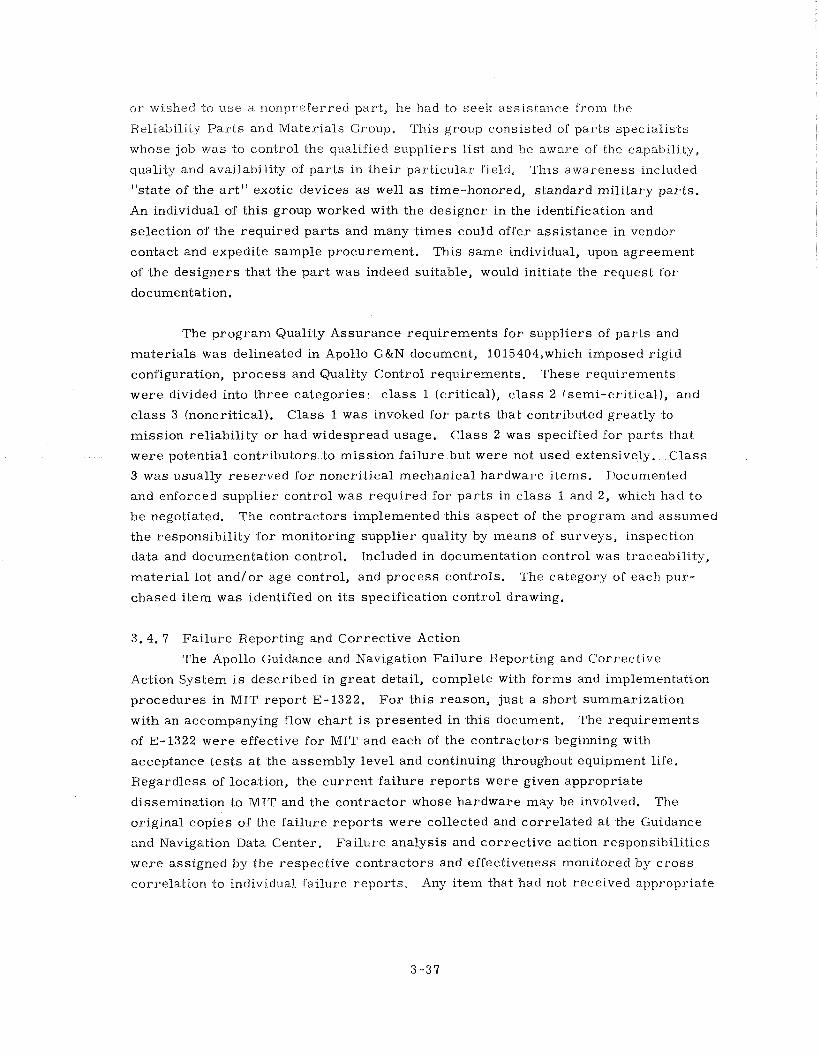
o r wished to use a nonpreferred par t , he had to seek assistance from the
Reliability P a r t s and Materials Group. This group consisted of par ts specialists
whose job was to control the qualified suppliers list and be aware of the capab~l i ty ,
quality and availability of pa r t s in their part icular field. This awareness Included
"state of the a r t " exotic devices a s well a s time-honored, standard mili tary par ts .
An individual of th is group worked with the designer in the identification and
selection of the required par t s and many times could offer assistance in vendor
contact and expedite sample procurement. This same individual, upon agreement
of the designers that the pa r t was indeed suitable, would initiate the request for
documentation.
The p rogram Quality Assurance requirements f o r suppliers of pa r t s and
mater ia ls was delineated in Apollo G&N document, 10 15404,which imposed rigid
configuration, process and Quality Control requirements. These requirements
were divided into three categories: c lass 1 (cri t ical) , c l ass 2 (semi-cri t ical) , and
c lass 3 (noncritical). Class 1 was invoked for p a r t s that contributed greatly to
mission reliability o r had widespread usage. Class 2 was specified fo r pa r t s that
were potential contributors to mission failure but were not used extensively. C lass
3 was usually reserved for noncritical mechanical hardware items. J)ocumented
and enforced supplier control was required for p a r t s in c lass 1 and 2, which had to
be negotiated. The contractors implemented this aspect of the program and assumed
the responsibility for monitoring supplier quality by means of surveys, inspection
data and documentation control. Included in documentation control was traceability,
mater ia l lot and/or age control, and process controls. The category of each pur-
chased i tem was identified on i t s specification control drawing.
3.4. 7 Failure Reporting and Corrective Action
The Apollo Guidance and Navigation Failure Reporting and Corrective
Action System is described in g rea t detail, complete with forms and implementation
procedures in MIT report E-1322. F o r this reason, jus-t a short summarization
with an accompanying flow char t i s presented in this document. The requirements
of E-1322 were effective for MIT and each of the contractors beginning wi-th
acceptance tests at -the assembly level and continuing throughout equipment life.
Regardless of location, -the current fai lure repor ts were given appropriate
dissemination to MIT and the contractor whose hardware may be involved. The
original copies of -the fai lure repor-ts were collected and correlated a t the Guidance
and Navigation Data Center. Failure analysis and correct ive ac.tion responsibilities
were assigned by the respective contractors and effec-tiveness monitored by c r o s s
correlation to individual failure repor ts . Any i tem that had no-t received appropriate
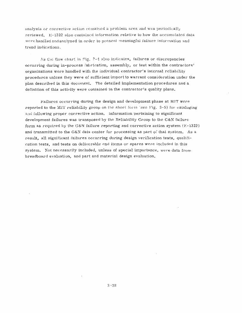
analysis o r correct ive action remained a problem a r e a and was periodically
reviewed. E-1322 a lso contained information relat ive to how the accumulated data
were handled and analyzed in order to present meaningful failure information and
trend indications,
A s the flow chart in Fig. 3-4 a lso indicates, fai lures o r discrepancies
occurring during in-process fabrication, assembly, o r test within the contractors '
organizations were handled with the individual contrac tor t s internal reliability
procedures unless they were of sufficient import to warrant consideration under the
plan described in this document. The detailed implementation procedures and a
definition of this activity were contained in the contractor ts quality plans.
Fai lures occurring during the design and development phase a t MIT were
reported to the MIT reliability group on the shor t foi , in see Fig. 3-5) for cataloging
a:ltl following proper corrective action. Information pertaining to significant
development fai lures was transposed by the Reliability Group to the G&N failure
fo rm a s required by the G&N failure reporting and corrective action system (E-1322)
and transmitted to the G&N data center for processing a s par t of that system. As a
result , a l l significant fai lures occurring during design verification tests, qualifi-
cation tests , and t es t s on deliverable end i tems o r spares were included in this
system. Not necessari ly included, unless of special importance, were data f r o m
breadboard evaluation, and par t and mater ia l design evaluation.
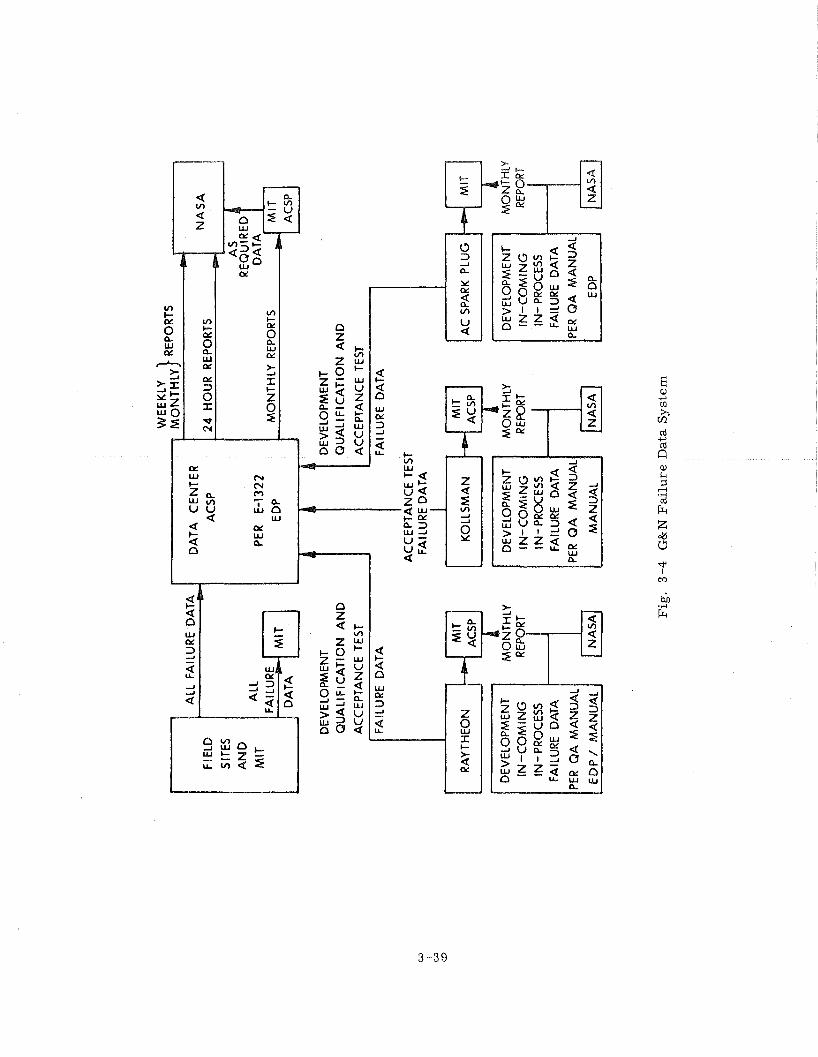
RA
YTH
EO
N
:$ I LY
FAIL
UR
E D
ATA
AC
CE
PTA
NC
E T
EST
FAIL
UR
E D
ATA
I 1
MIT
K
OLL
SM
AN
A
CSP
DE
VE
LOP
ME
NT
IN-C
OM
ING
IN
- PR
OC
ESS
FAIL
UR
E D
ATA
PE
R Q
A
MA
NU
AI
MA
NU
AL
I M
ON
THLY
RE
PORT
NA
SA
I AC S
PARK
P
LUG
I
IN-C
OM
ING
IN
- PR
OC
ESS
FAIL
UR
E D
ATA
PER
QA
M
AN
UA
L
I E
DP
1
MO
NTH
LY
REPORT
Fig
. 3
-4
G&
N F
ail
ure
Dat
a S
yst
em
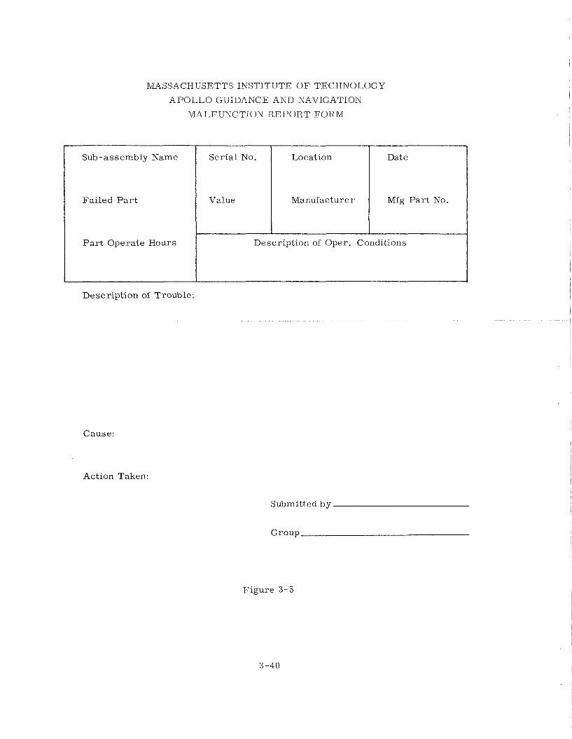
MASSACHUSETTS INSTITUTE O F TECHNOLOGY
A P O L L O GUIDANCE AND NAVIGATION
MALFUNCTION R E P O R T F O R M
Description of Trouble:
Sub-assembly Name
Failed P a r t
P a r t Operate Hours
Cause:
Action Taken:
Submitted by
Group
Ser ia l No.
Value
Figure 3-5
Description of Oper. Conditions
Location
Manufacturer
Date
Mfg P a r t No.
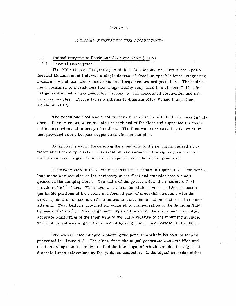
Section IV
INERTIAL, SUBSYSTEM (ISS) COMPONENTS
4 . 1 Pulsed Integrating Pendulous Accelerometer (PIPA)
4. 1.1 General Description.
The PIPA (Pulsed Integrating Pendulous Accelerometer) used in the Apollo
Inertial Measurement Unit was a single degree -of-freedom specific force integrating
receiver , which operated closed loop a s a torque-restrained pendulum. The ins t ru-
ment consksted of a pendulous float magnetically suspended in a viscous fluid, s ig-
nal generator and torque generator microsyns, and associated electronics and cal -
ibration modules. Figure 4-1 is a schematic diagram of t.he Pulsed Integrating
Pendulum (PIP).
The pendulous float was a hollow beryllium cylinder with built-in m a s s imbal-
ance. F e r r i t e r o t o r s were mounted at each end of the float and supported the mag-
netic suspension and microsyn functions. The float was surrounded by heavy fluid
that provided both a buoyant support and viscous damping.
An applied specific force along the input axis of the pendulum caused a r o -
tation about the output axis. This rotation was sensed by the signal generator and
used a s an e r r o r signal to initiate a response from the torque generator.
A cutaway view of the complete pendulum is shown in Figure 4-2. The pendu-
lous m a s s was mounted on the periphery of the float and extended into a smal l
groove in the damping block. The width of the groove allowed a maximum float
rotation of f lo of a rc . The magnetic suspension s t a to r s were positioned opposite
the inside portions of the ro to r s and formed part of a coaxial s t ructure with the
torque generator on one end of the instrument and the signal generator on the oppo-
si te end. Four bellows provided for volumetric compensation of the damping fluid
between loOc - 71°c. Two alignment r ings on the end of the instrument permitted
accurate positioning of the input axis of the PIPA relat ive to the mounting surface.
The instrument was aligned to the mounting ring before incorporation in the IMU.
The overa l l block diagram showing the pendulum within its control loop is
presented in Figure 4-3. The signal f rom the signal generator was amplified and
used a s a n input t o a sampler (called the interrogator) which sampled the signal at
d iscre te t imes determined by the guidance computer. J3 the signal exceeded ei ther
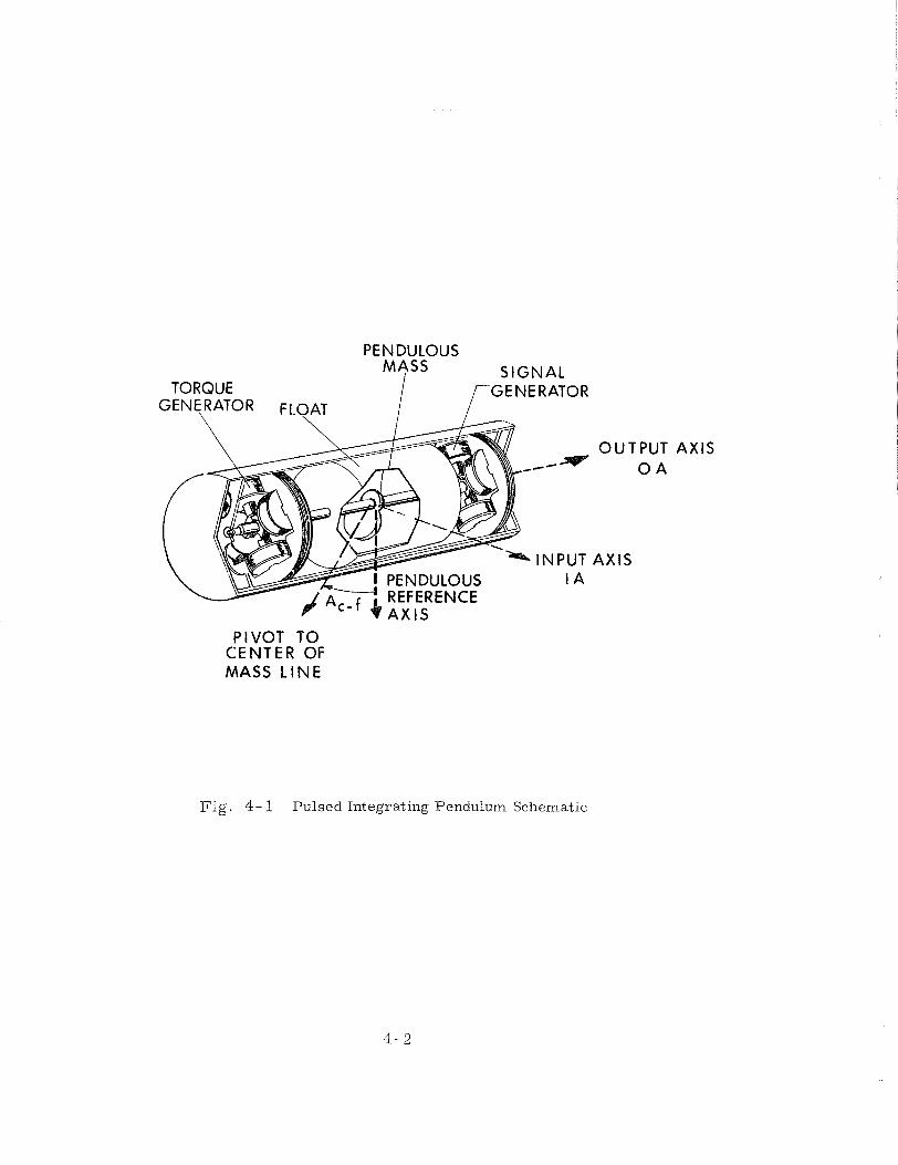
PENDULOUS MASS SIGNAL
TORQUE GEN'RATOR FLOAT [ GENERATOR
OUTPUT AXlS z-- * 0 A
INPUT AXlS I A
PIVOT TO CENTER OF MASS LINE
Fig. 4- 1 Pulsed Integrating Pendulum Schematic
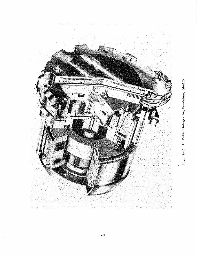
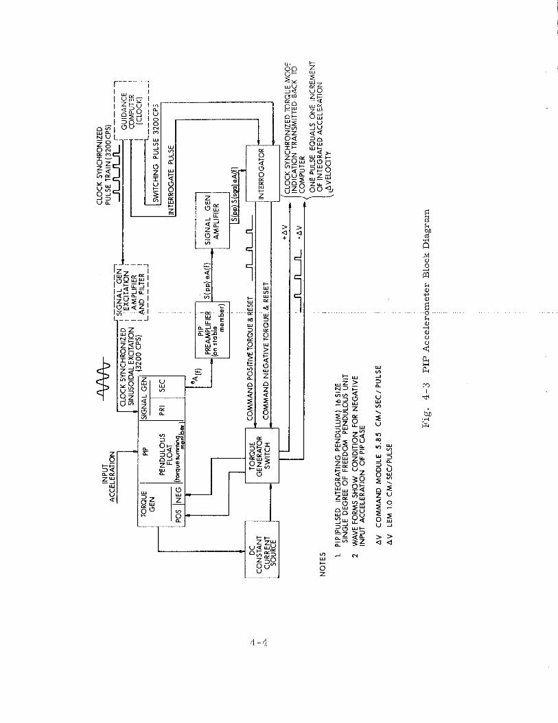
I A
MP
LIFI
ER
I
I A
ND
FI
LTER
I
L ------- J
I C
LOC
K S
YN
CH
RO
NIZ
ED
TO
RQ
UE
MO
DE
n -AV
\IN
DIC
AT
ION
C
OM
PU
TER
TR
AN
SM
ITTE
D B
AC
K
TO
NO
TE
S
1. P
IP(P
ULS
ED
IN
TE
GR
AT
ING
PE
ND
ULU
M)
16 S
IZE
SIN
GLE
DEG
REE
OF
FR
EE
DO
M
PE
ND
ULO
US
UN
IT
2 W
AV
E F
OR
MS
SH
OW
CO
ND
ITIO
N
FOR
NE
GA
TIV
E
INP
UT
AC
CE
LER
ATI
ON
OF
PIP
CA
SE
ON
E P
ULS
E E
QU
ALS
ON
E I
NC
RE
ME
NT
OF
INTE
GR
ATE
D A
CC
ELE
RA
TIO
N
,AVE
LOC
lTY
AV
C
OM
MA
ND
MO
DU
LE
5.8
5
CM
/ S
EC
/ P
ULS
E
AV
LE
M 1
.0 C
M/S
EC
/PU
LSE
Fig
. 4
-3
PIP
Accele
rom
ete
r B
lock
Dia
gra
m
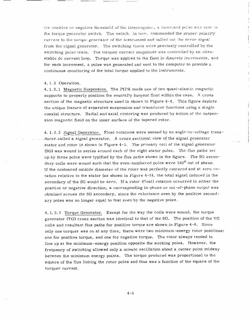
the positive o r negative threshold of the interrogator, a command pulse was sent to
the torque generator switch, The switch, in turn, commanded the proper polarity
current to the torque generator of the instrument and nulled out the e r r o r signal
from the signal generator. The switching t imes were precisely controlled by the
switching pulse t ra in . The torquer current magnitude was coritrolled by an u l t r a -
s table dc cur ren t loop. Torque was applied to the float in d iscre te increments, and
fo r each increment , a pulse was generated and sent to the computer to provide a
continuous monitoring of the total torque applied to the instruments.
4. 1. 2 Operation.
4. 1. 2. 1 Magnetic Suspension. The PIPA made use of two quasi-elastic magnetic
supports to properly position the neutrally buoyant float within the case. A c ross
section of the magnetic s t ruc tu re used is shown in Figure 4-4. This figure depicts
the unique fea ture of separated suspension and transducer functions using a single
coaxial s t ructure . Radial and axial centering was produced by action of the suspen-
s ion magnetic field on the inner surface of the tapered rotor .
4. 1. 2 . 2 Signal Generator. Float rotations were sensed by a n angle-to-voltage t r ans -
ducer called a signal generator. A c r o s s sectional view of the signal generator
s t a to r and rotor i s shown in Figure 4-5. The pr imary coil of the signal generator
(SG) was wound in s e r i e s around each of the eight s ta tor poles. The flux paths s e t
u p by these poles were typified by the flux paths shown in the figure. The SG secon-
da ry coils were wound such that the even-numbered poles were 180' out of phase.
If the contoured outside diameter of the ro tor was perfectly centered and at z e r o ro -
tation relat ive to the s t a to r (as shown in Figure 4-5), the total signal induced in the
secondary of the SG would be zero . If a rotor (float) rotation occurred in ei ther the
positive o r negative direction, a corresponding in-phase o r out-of-phase output was
obtained a c r o s s the SG secondary, since the reluctance seen by the positive second-
a r y poles was no longer equal to that seen by the negative poles.
4 .1 . 2 . 3 Torque Generator. Except for the way the coils were wound, the torque
generator (TG) c r o s s section was identical to that of the SG. The position of the TG
coils and resultant flux paths for positive torque a r e shown in Figure 4-6 . Since
only one torquer was on a t any t ime, there were two minimum-energy rotor positions:
one for positive torque, and one f o r negative torque. The rotor always tended to
l ine up a t the minimum-energy position opposite the working poles. However, the
frequency of switching allowed only a minute oscillation about a center point midway
between the minimum energy points. The torque produced was proportional to the
square of the flux linking the ro tor poles and thus was a function of the square of the
torquer current .
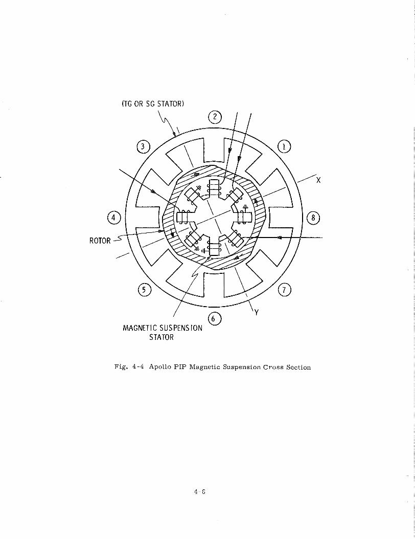
(TG OR SG STATOR)
MAGNET1 C SUSPENSION w
Fig. 4-4 Apollo PIP Magnetic Suspension Cross Section
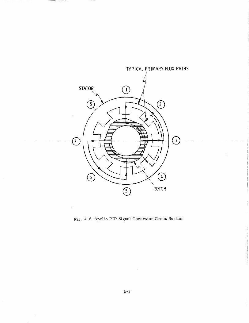
TY P I CAL PR IMARY FLUX PATHS
4'
Fig. 4-5 Apollo PIP Signal Generator C r o s s Section
ROTOR
TORQUE CURRENT RETURN cq TORQUE CURRENT
TORQUE CUR t
L J FLUX PATHS FOR POS IT lVE TORQUE
Fig. 4 -6 Apollo PIP Torque Generator
The resulting torquing loop was a two-state o r binary loop with torque
applied continuously in ei ther positive o r negative directions. The mode of
oscillation of the float was determined by the design parameters of the instrument.
If m pulses occurred alternately in each direction, an m:m mode was declared to
exist.
The velocity equivalent of one torque pulse was defined a s the scale factor
of the instrument having the units of cm/sec/pulse. Inequalities in the positive and
negative torquing circuits caused an imbalance in the resulting output pulse t r a in
(with no input). The measure of this imbalance was defined a s the bias. Bias was
usually defined in t e r m s of a n equivalent acceleration applied to the float; e. g. , a bias of 1 dyne cm is equivalent to a n acceleration of 4 cm/sec2 applied to a
float having a pendulosity of 0. 2 5 gm cm .
4. 1. 2.4 Ducosyn Flux Patterns. Figure 4-7 shows the flux pattern present in the
ducosyn. The heavy lines represent the flux paths fo r the odd poles (+ torque) and
the dashed l ines represent the flux paths for the even poles ( - torque). Also shown
a r e the flux paths fo r the magnetic suspension. Since the rotor was a single f e r r i t e
piece, these fluxes were al l superimposed in the rotor. The single piece fe r r i t e
ro tor used in the Apollo PIP allowed interaction of the suspension and torquer
fluxes. Assymmetr ies in the superposition of these fluxes in the ro to r could have
caused variations in PIPA bias which were dependent upon the phase relationship
of the fluxes. Operation in the r e v e r s e torquer configuration ( reversa l of current
flow in one torque winding) brought about a symmetric superposition of fluxes which
would be almost independent of phase and would have reduced any bias changes to
second order .
Three different conditions of flux were present in the s ta tor . The flux
existing in the poles was the on-off type, a s shown. The flux in the back i ron
section, b, d, f and h, reached a dc level once the unit was turned on. (This
condition remained constant except fo r a slight transient that occurred at switching
intervals. ) The flux in sections a , c, e and g was a n alternating one. The s ta tor
flux magnitude should not have changed regardless of the torquer winding that was
being energized; only the duty cycle of the positive and negative pulses should
have changed. Changes in the permeability of the ducosyn mater ia ls would cause
variations in the flux magnitude resulting in changes to the sca le factor and bias.
Permeabil i ty changes could have occurred a s a result of transient overshoots in the
torquer o r suspension currents a t system turn-on and by s t r e s s e s incurred a s a
resul t of slow curing of microsyn encapsulating materials .
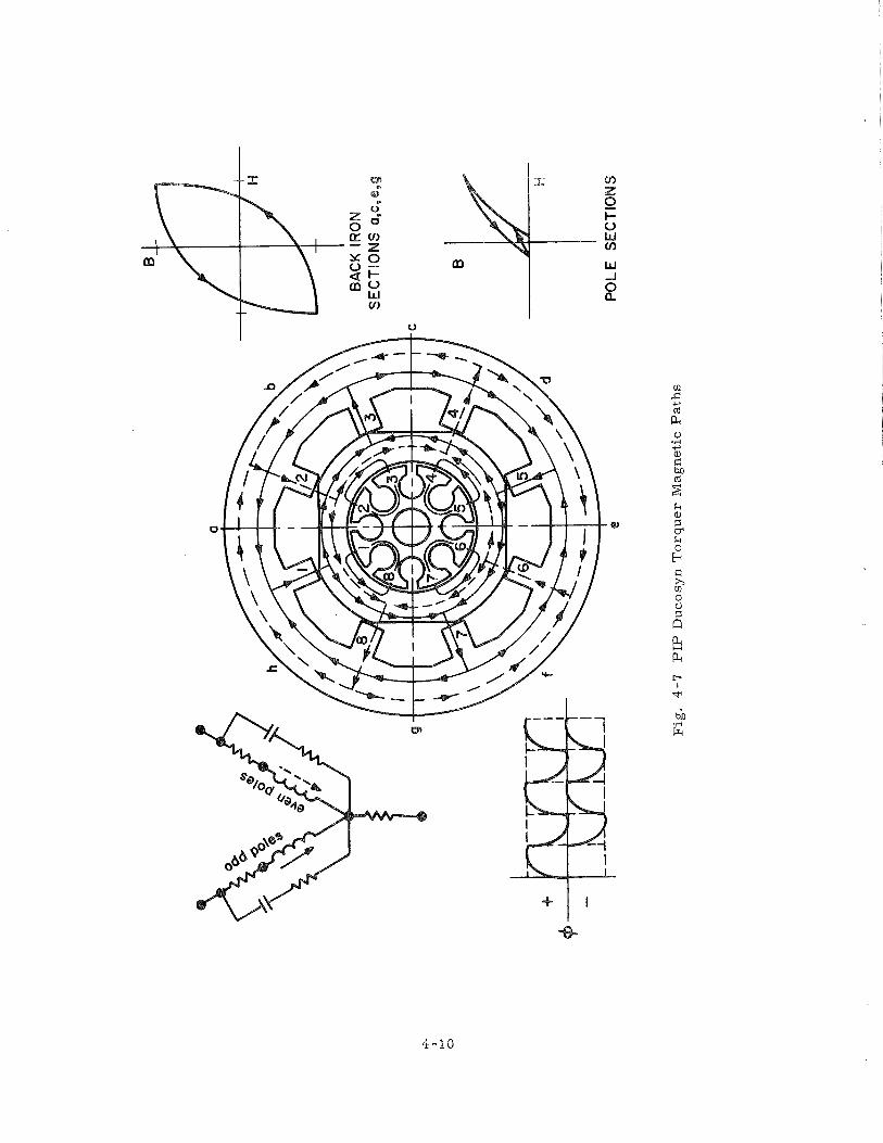
4 . 1, 2 . 5 Electronics, A functional description of the electronics involved with P IPA
operation i s depicted in the control-loop block diagram, Figure 4-3 . The fi l tered
SG signal was amplified by the preamplif ier and a c differential amplif ier and sent
to the interrogator. The interrogator utilized a dual channel peak detector that was
synchronized by the interrogator pulse t ra in from the computer o r system clock to
determine the polarity of the signal from the a c amplif ier . The outputs from the
peak detector controlled the s t a t e of two multivibrators that commanded either
positive o r negative torque from the switch.
The binary current switch controlled the direction of the current flow from
the cur ren t source in accordance with the commands received from the interrogator.
A switch pulse-train synchronized the switching of the second multivibrator s tage in
the interrogator such that the pulses of current sent through the t2rque windings
were of equal width.
The current loop is expanded in Figure 4-8. The output of the switch was
sent to the calibration module. This module provided the necessary passive com-
ponents to make the torquer coils of the PIP appear purely res is t ive thus controlling
switching transients and optimizing current stability. Bias adjustment was obtained
by u s e of the res is t ive shunting circuit. Fine padding of the res is t ive loads, R1, in
s e r i e s with the torque windings, allowed equalization of the t ime constants, T I and
The voltage drop a c r o s s the sca le fac tor (SF) r e s i s t o r was compared with a
precision voltage reference (PVR). The e r r o r voltage was amplified by a high-gain
dc differential amplif ier and used to control the current magnitude i n the loop.
4. 1, 2 . 6 Mode of Operation. Initially, the Block I Apollo torquing loop was designed
a s a three-state o r t e rna ry loop with no torquing pulses applied to the float if the
output of the a c amplifier was l e s s than the interrogator threshold. This approach
was taken to conserve spacecraft power. Testing of the ea r ly PIPAs revealed that,
a s a resul t of the magnetic hysteres is of the torquer s ta tor and ro to r mater ia l , a
significant residual flux remained in the c o r e when the torquing cur ren t was removed
and caused the instrument to show la rge bias variations that were dependent on the
polarity of the l a s t applied torquing pulse. I t was further determined that the r e s i -
dual effects could b e largely eliminated if al ternate torquing were imposed contin-
uously on the torquers thus creating a near ly constant average magnetic s t a t e in the
mater ia ls . Consequently, a decision was made to establish a binary loop to neutra-
l i z e the effects of the hysteres is .
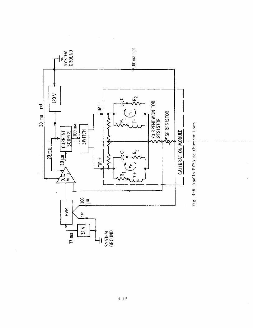
20 m
a re
t
L CA
LI B
RATI
ON
MO
DULE
----- A
Fig
. 4
-8
Ap
oll
o P
IPA
dc
C
urr
en
t L
oo
p
4.1, 3 Problems and Solutions,
4.1.3. f Scale Factor Instabilities. (I) Torque Current Overshoot - - Torque current
t rans ients in excess of normal operating current levels will change the permeability
of ducosyn magnetic mater ia ls by raising the operating level on the B-R curve. Th i s
phenomenon was identified ea r ly in the program. It resulted f rom the finite Lime
required fo r the torquing electronics to stabilize during turn-on and a lso because of
the decay character is t ics of the electronics during turn-off. Design changes were
made in the electronics which limited these transients to acceptable levels.
(2) Excitation Overshoot -- Superposition of torquer and suspension fluxes in
the f e r r i t e ro tor can resul t in portions of the ro tor being pushed f a r into saturation
if an excitation overshoot occurs a t the t ime one torquer is full-on. This phenomen-
on was demonstrated a t both the microsyn and completed instrument levels. The
complexities of the IMU ci rcui t ry thus f a r has not permitted the demonstration of
th is phenomenon at the system level. However, data analysis plus experimental
evidence that large scale fac tor and bias shifts occurred frequently a c r o s s IMU turn-
off and turn-on, gave indications that excitation overshoot effects were a definite
possibility,
(3) Long T e r m Drift -- Long t e r m curing of the torquer microsyn encapsu-
lating mater ia l caused variations in the s t r e s s e s exerted on the torquer stator by the
encapsulant. The permeability of the torquer stator varied a s a function of the
change in s t r e s s e s with a result ing <hange in the scale factor of the instrument. The
scale factor change was initially about -150/ppm/month but exponentially decayed t o
nearly ze ro in 12 t o 18 months. The magnitude of the scale factor change was p re -
dictable once a history of scale factor measurements of the unit w a s established
and accounted for.
(4) Pendulosity Change - - On severa l ea r ly Block I1 units, the hollow float
used i n the PIP was not adequately sealed and damping fluid leaked into i t s interior.
The presence of damping fluid in the float produced a variable additive component
of pendulosity. Since scale factor is inversely proportional to pendulosity, a l a rge
and unstable change i n scale factor resulted. The sealing technique used with
these units was devised for a l e s s viscous adhesive than was actually used resul t ing
i n an improper adhesive flow and a poor bond. An improved sealing technique w a s
developed, however, which corrected this problem.
4.1. 3 . 2 Bias ~ n s t a b i ~ i t i e s . ( l ) Excitation Overshoot -- A s discussed in the previous
section, excitation overshoots could have occurred i n the Apollo IMU. If the ro to r
saturation caused by the overshoot affected both torquers equally, only a scale factor
shift would have occurred. To the extent that the saturation effects were asymmet-
r ica l , a bias shift would result.
( 2 ) Ac Hysteresis - - The te rm ac hysteresis is applied Lo bias variations
caused by suspension fluxes coupling through fringe portions of the rotor when the
float i s allowed to rotate to an angular stop. This effect was controlled by adequate
specification of the magnetic properties of the rotor material.
( 3 ) Position Memory - - Position memory was an acceleration bias exhibited
by the PIPAs. Position memory caused a bias change of 0 . 1 cm/sec2 for an accel-
erometer input ranging from 0 to - + 1 g. The change in position memory bias as a
function of imput acceleration was predictable and thus was compensated for since
the expected acceleration profile was known. It was thought that eddy currents in
the stator were a contributing factor to position memory. The eddy currents caused
the flux levels in the stator to be frequency dependent. In the presence of an accel-
eration, the frequency of the binary torquing (either plus o r minus ) would vary and,
a s a result, the average flux levels would likewise vary. The net result was an ac-
celeration dependent imbalance between the plus and minus torquing loops. A possible
cure fo r this phenomenon is currently under investigation and involves using a torque
generator s ta tor material of higher resistivity thus reducing the magnitude of the
induced eddy currents. Preliminary tests indicated that this approach has some
merit .
( 4 ) Reversal of Torque Location - - The original PIP design had the torque
generator located at the end of the instrument that contained the mounting arrange-
ment. It was noted that bias changes were affected by s t resses applied to the torquer
by the clamping forces used during PIP alignment. The torquer was placed on the
outboard end of the PIP, and a major source of bias changes was removed.
( 5 ) Fluid Impurities - - Contaminants o r gas bubbles within the damping fluid
can become positioned between the float and the case of the PIPA exerting e r ro r
torques on the float. Proper filling techniques would minimize the possibility of
foreign particles in the fluid at the time of manufacture. Gas bubbles could result
from a i r leaking into the instrument from outside o r from helium gas leaking into
the fluid from the hollow float o r from the bellows.
A cemented metal band was used to seal the joint between the two end housings
of the PIP. This joint, a s well a s the float and bellows seals, was carefully checked
before filling the unit with damping fluid. Filling the instrument was accomplished
through small f i l l holes at either end of the case. Once filled these holes were sealed
using metallic compression seals.
By use of the above Lechniqiue, the possibility of air leaking into the ins t ru-
ment was virtually eliminated, Slow leakage f rom the float could easi1.y be kept to
acceptable levels with known cementing and fabrication techniques.
The bellows remained one of the most cr i t ica l elements in the design. Rigid
screening t es t s on the bellows and careful inspection by X-ray techniques a l t e r
completion resulted in bellows failures becoming r a r e occurrences.
4.1.3.3 Input Axis Instabilities. ( 1 ) Fluid in the Float - - As discussed in the above
section on scale factor instabilities, some Block I1 units leaked damping fluid into
the hollow float resulting in pendulosity changes. The pendulosity changes were both
in magnitude and direction, the directional changes causing an IA shift within the
unit. In the case of these units, the IA shifts obtained were large (> 10 zn).
( 2 ) Fluid Behind Rotors - - During the Block I1 program, a minor IA shift
problem was discovered on some units. The ra te of IA shift was in most cases l e s s
than 20 =/ day. The cause of the shift was traced t o the existence of smal l crevi-
c e s behind the rotor which became only partially filled with damping fluid a t the t ime
of fill. The fluid within these crevices was then f r e e to move within a limited channel
behind the rotor a s a function of the position of the instrument relative to the gravity
vector. Recent changes in the rotor assembly technique were expected to eliminate
this problem.
( 3 ) Suspension Hang-Up - - Suspension hang-up is caused by the a i r gap be-
tween the suspension s ta tor and rotor on a given suspension becoming large enough
to cause the unit t o operate at , o r slightly beyond, resonance. Because of build
tolerances which cannot be easily tightened, a smal l possibility exists that an Apollo
pendulum may hang-up if the float is allowed to sett le into an axial extreme. As a
precautionary measure , a l l PIPS were required to pass a suspension hang-up t es t
which insured that the float would re-center f rom any possible r e s t position.
( 4 ) Temperature Sensor - - After severa l fa i lures with the original sensor ,
it became apparent that the sensor leads should have been attached to the flat wire
sensor on the P I P with a s t ra in loop. This design change was complied with ear ly
in production. A res is tance check using a megohmmeter was introduced in o r d e r to
eliminate any unit which might have suffered a shorting-type failure resulting f r o m
assembly pressures .
( 5 ) Moding Change - - Utilization of the binary torquing loop in the Apollo
PIPA resulted in a stable oscillation of the float about its null, o r minimum TG
output signal, The number of torque pulses occurring during each positive o r
negative going half-cycle was an indication of the operational mode; i. e . , two pulses
alternately in each direction was defined a s a 2 :2 mode. The mode actually obtained
f o r a given instrument was dependent on a number of parameters , including the
angular moment-of - inert ia of the f10s.t~ the T G sensitivity, the magnitude of the
torque pulse, and the viscous damping.
E a r l y Block I units moded a mixed 3:3 plus 4:4. The presence of the 4:4
mode required additional computer t ime. Accordingly, the viscous damping in the
PIPA was increased to a value which would insure the elimination of the 4:4 mode.
( 6 ) Gaussing - - Gaussing is a t e r m used to describe bias changes resulting
f r o m variat ions in the magnetic s t a t e of the TG r o t o r / s t a to r pair . The ro to r opera tes
a s pa r t of the suspension and torquer magnetic circuits . Current overshoots in
ei ther of these two c i rcui ts would have produced non-reversible changes in the mag-
netic operating point of the ro tor mater ia l . Fur thermore , l a rge changes in ro to r
orientation such a s torquing of the ro to r to a ro tary stop because of a malfunction
in the torquing circuit would have caused changes in the magnetic s ta te a s a resul t
of disaccommodation. :%
In an adequately controlled environment, gaussing would not constitute a
problem. However, the Apollo sys tem was not immune to transients ( particularly
during turn-on, turn-off sequences) , and gaussing did occasionally occur.
Theoretically, degaussing is the elimination of a gaussed condition by the
application of a high level a c flux to the torquing circuit. The flux level is reduced
gradually to z e r o and in theory should resul t in no magnetic hysteres is in the mater ia l .
In practice, however, the mate r i a l was found to exhibit s o m e residual hysteres is
a f t e r degaussing. If the degaussing operation was always performed in an identical
manner, a fixed residual was obtained, with a corresponding repeatable bias level.
However, s o m e variat ions normally occurred in the manual degauss cycles with
resultant bias variations. The u s e of a n automatic degausser optimized the degauss
cycle repeatability and normally resulted in a stable reference bias level.
4. 1.4 P I P R e p a i r l ~ e d e s i g n Program.
An improved configuration was developed fo r the PIP repa i r program. The
redesign was instituted in an effort to eliminate fai lures result ing from bubbles and
accumulations of fluid in o r around the float. Sample instruments were built and
*~isaccornmodat ion i s a time-dependent variation in the permeability of a magnetic ma te r i a l following a change in the magnetic field within the mater ia l .
the design was verified, NASA then contracted with Sperry to do fai lure analysis
and verification, rebuilding and testing of 50 PIPS, the majori ty of which were
internal r epa i r units.
4 , 1.5 Conclusions
With the experience of seven y e a r s , numerous conclusions may be drawn
regarding the good and bad features of the program.
(1) Since the basic P I P represented a m o r e sophisticated version of the
Po la r i s P IP , which had been in production fo r some t ime, most technical problems
occurred in external a r e a s of the new instrument such a s modules, cabling, con-
nectors and alignment r ings .
(2 ) The importance of a reasonable degree of personnel and organizational
stability cannot be overemphasized. MIT maintained a constant group on the task,
whereas the Sper ry engineering and production groups experienced some shifting of
personnel. The program by and l a rge was a successful one, certainly to the extent
that changes, improvements, and correct ions , where required, were integrated into
production with a minimum of impact to a n uninterrupted delivery of PIPS to the
program.
( 3 ) Monitoring of instrument performance i n the field, coupled with a n active
fai lure analysis and correct ive action program, provided the m eans for revealing
any deficiencies i n the design o r construction of the instrument. As the quantity of
occurrences of each recognized example of degraded performance o r field fa i lure
reached a stat ist ically meaningful total, analytical and correlat ive techniques be-
came effective i n diagnosing the basic cause of the problem thus permitting appropri-
a te corrective action.
(4) Any reliability t e s t program aimed a t determining the life character is -
t ics of a component such a s the Apollo accelerometer must be most carefully planner
and executed if meaningful resul ts a r e to be achieved. The 16 P I P life t e s t prograrr
was initiated with the purpose of determinimg a n MTBF for this component of the
Apollo guidance sys tem.
The planning of this t e s t program proved difficult from the very beginning.
F i r s t , there were no recognized normal field fa i lure modes fo r the 16 P IP . The
build process and the acceptance tes t cycle was designed to eliminate the likelihoc
of electr ical shor t s o r opens and particulate ma t te r i n the damping gaps, these bej
the only recognized fai lure modes. With only nine units assigned to the program,
i t was recognized that thousands of hours of operation might well generate no fai lures
at all, This turned out to be the case. Performance limits were therefore set up ,
more o r less arbitrarily, to provide some measure of the operational reliability of
the instrument. Some attempts were made to determine environmental effects but,
because of the Limited number of sample units available, no definitive results could
be obtained. Because of the unavailability of a sufficient number of regular test
consoles and the desire to avoid impacting the acceptance testing schedule, special,
relatively inexpensive, electronic run-in equipment was designed and constructed.
The instvuments were operated on a long term, continuous basis on this s e t -
up and transferred to a regular test station at periodic intervals for official data
checks. Puzzling performance differences were noted when comparing results ob-
tained at the electronic run-in station versus those secured at the console test
station. The inconsistencies in the data could not be explained by the test and
engineering information then available. Eventually, the reasons for these inconsis -
tencies were learned, and it was then apparent that the life test setup was not suitable
for evaluating the instrument performance. The effort was therefore terminated.
4.1.6 Recommendations
The results of seven years of experience with the 16 PIP MOD D, a s used in
the Apollo guidance system, have shown the instrument to be basically an excellent
one fo r the intended purpose. The effect of system interfaces on performance have
been throughly studied. The deficiencies of the instrument have, to a great extent,
been revealed and corrective action taken to eliminate o r minimize them.
A limited number of conditions sti l l remain for which an explanation and
effective corrective action have not yet been developed.
( 1 ) Analysis of repair unit failure data revealed that a sizable percentage of
units experienced a shift in uncompensated bias in excess of that which could be
ascribed to test equipment variation. Investigation into the cause of this shift should
determine whether the shift is stable, thus permitting the use of these instruments
and eventually allowing development of corrective action to eliminate this condition.
( 2 ) Certain anomalies in the bias performance characteristics have been
identified a s resulting from disaccommodation in the ferrite material o r the PIP rotor. '
Work is underway to improve the magnetic structure of the ferr i te in order to mini-
mize the disaccommodation.
( 3 ) Certain other anomalies in the bias performance characteristics do not
appear to be related to the disaccommodation phenomenon, and the cause i s a s yet
undetermined. This anomaly is identified as position memory.
( 4 f There is another magnetic effect associated with gaussing which causes
both bias and sca le fac tor variat ions in performance. An effort to make u s e of an
u l t r a - s ensitive airbearing torque -to -balance loop in a n attempt to identify and quan -
tify th is effect is underway.
4.2 Inert ial Reference Integrating Gyro ( IRIG)
4 . 2 . 1 General Description
The Apollo Block I IRIG was basically a modification of the type of gyro
used in Polar is , that is, a single degree of freedom, floated integrated instrument.
Its wheel assembly was supported by a pa i r of preloaded angular contact ball bea r -
ings adjusted to give an isoelast ic s t ruc tu re having equal compliance along the spin
and output axes. It was enclosed in a sealed, spher ica l beryllium float. The wheel
assembly was driven by a hysteres is synchronous motor in an atmosphere of helium
which prevented corros ion of the f e r r o u s pa r t s and a lso provided good heat t r a n s -
f e r within the float. The float assembly was suspended in a brominated fluorocarbon
flotation fluid which provided flotation and damping. The fluid was fractionally
distilled to yield polymers of approximately the s a m e length and nearly the s a m e
viscosity. This minimized fluid stratification under operating and s torage conditions.
A ducosyn a t each end of the unit performed the task of signal and torque genera-
tion.
A ducosyn consists of a separa te magnetic suspension assembly, a separa te
t r ansducer microsyn mounted a s a single coaxial-coplanar unit, and contains two
separa te s t a to r s mounted to the c a s e and two separa te ro to r s mounted on a common
ring on the f loat assembly. The signal generator ducosyn was mounted on the posi -
t ive output axis end of the float to provide magnetic suspension and s e r v e a s a
t r ansducer to provide an e lec t r ica l analog signal proportional to the position of the
float. A torque genera tor ducosyn was mounted on the negative output axis end of
the float to provide magnetic suspension and s e r v e a s a t ransducer to convert an
e lec t r ica l e r r o r s ignal into a torque about the output axis.
The IRIG character is t ics a r e summarized in the following table.
ELEMENT TYPE SPECIFICATIONS
Wheel a s s em bly 2 8 Volt, 2 phase, 800 Hz Angular momentum: 6 2 0.434 X 10 gm cm / s e c
a t 24,000 rpm
ELEMENT
Damper
Signal generator
Torque generator
T Y P E SPECIFICATIONS
Brominated Fluorocarbon Damping coefficients:
Density 2.38 5 gm/ cc at 5
about OA: 4 - 7 5 X 10 dyne
1 3 7 ~ ~ c m / rad / s e c 9
about IA: 1 .5 X 10 dyne c m / rad / s e c
9 about SRA: 1 .5 X 10 dyne
e m / rad / s e c
8 pole 33-connected mic ro- Angle sensitivity:
syn 4V, 3200 Hz 10mV / m r
1 2 pole modified E - torque sensitivity T (+)
c o n n ection with r e s e t o r T ( - ) to common:
and bias compensation 0.6 dyne cm / m a 2
windings.
Magnetic suspension Tapered, 20' included Radial stiffness 6 gm / angle 0.0001 inch
Axial stiffness 0.8 gm / 0.0001 inch
Temperature Sensors Two thermis tors on Resistance:
each end housing 345 ohms a t 137' F
suspended in fluid Resistance gradient:
6 ohms 1" F / thermis tor
Mechanical Character - (1) Shroud jacket: provides magnetic shielding and
is t ics vacuum envelope f o r the gyro.
Prealignment unit (2) Size: 2.810 dia X 5. 10 in.
(3) Weight: 1.97 lbs.
F igure 4-9 is an illustration showing the main features of the gyro instrument.
During final LRIG assembly, a prealignment package was added to the signal genera-
t o r end of the gyro case. Addition of this package made the gyro a prealigned unit.
The package contained the following components :
( 1 ) Suspension capacitors fo r ducosyn suspension.
( 2 ) Temperature sensor normalization.
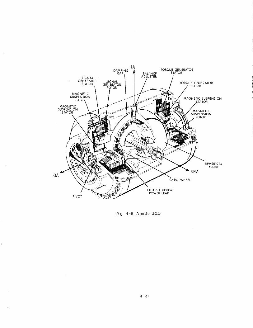
Fig. 4-9 Apollo IRIG
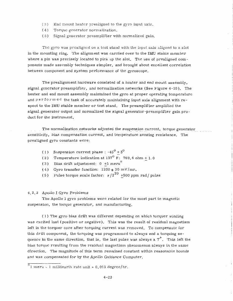
( 3 ) End mount heater prealigned to the gyro input axis.
( 4 ) Torque genera tor normalization.
( 5 ) Signal genera tor preamplif ier with normalized gain.
The gyro was prealigned on a t e s t stand with the input axis aligned to a slot
in the mounting ring. The alignment was ca r r i ed over to the IMU stable member
where a pin was precise ly located to pick up the slot. The use of prealigned com-
ponents made assembly techniques s impler , and brought about excellent correlat ion
between component and sys tem performance of the gyroscope.
The prealignment hardware consisted of a heater and end mount assembly,
signal generator preamplif ier , and normalization networks (See Figure 4-10 ). The
heater and end mount assembly maintained the gyro a t proper operating temperature
and P e r f 0 r m e d the task of accurately maintaining input axis alignment with r e - spect to the IMU s table member o r t e s t stand. The preamplif ier amplified the
signal generator output and normalized the signal generator-preamplif ier gain p ro -
duct f o r the instrument.
The normalization networks adjusted the suspension current , torque genera tor
sensitivity, bias compensation current , and temperature sensing resistance. The
prealigned gyro constants were:
( 1 ) Suspension current phase : -45' + 3O - ( 2 ) Temperature indication a t 137' F : 769. 6 ohm + 1. 0
4, -
( 3 ) Bias drift adjustment: 0 +5 m e r ~ ' ~ - ( 4 ) Gyro t r ans fe r function: 1200 & 30 m ~ / m r .
( 5 ) Pulse torque sca le factor: n /2" +500 ppm r a d / pulse -
4.2.2 Apollo I Gyro Problems
The Apollo I gyro problems were related f o r the mos t par t to magnetic
suspension, the torque generator, and manufacturing.
( 1 ) The gyro bias drif t was different depending on which torquer winding
was excited l a s t (posi t ive o r negative). This was the resul t of residual magnetism
left in the torquer co re a f t e r torquing current was removed. To compensate fo r
this drif t component, the torquing was programmed t o always end a torquing s e - +
quence in the s a m e direction, that is, the last pulse was always a T . This left the
bias torque resulting f r o m the residual magnetism phenomenon always in the same
direction. The magnitude of this t e r m remained constant within reasonable bounds
and was compensated f o r by the Apollo Guidance Computer.
:;: 1 m e r u = 1 rnilliearth ra te unit = 0.015 degree lh r .
f SPARES
f L N T
AWLLO n laic
O W N N A. r 0- 8. lu Tu
Fig. 4-10 Apollo I1 IRIG Prealignment Network
( 2 ) The gyro floats displaced radially when the torquer was energized.
This displacement resulted f rom asymmetr ies that were attributable to manufactur-
ing tolerance buildup, and to tolerances associated with how closely the magnetic
suspension centering could be achieved. Some units that were displaced to thei r
jewel extremes during torquing resulted in up to 2% pulse torque scale factor un-
certainty ( The required stability was 0. 1%. ) The value of the magnetic suspension
damping res i s to r was correspondingly decreased to stiffen up the magnetic suspen-
sion thus reducing the radia l displacement when the torquer was energized.
( 3 ) Some of the f i r s t units developed acquired suspension shor ts to the gyro
end housing. These shor t s were caused by insufficient insulation between the end
housing printed circuit boards and the mu-metal shields. This problem was recog-
nized and corrected by providing more clearance between the printed circuit pins
and the mu-metal shield, and by increasing the thickness of insulation between the
printed circuit board and the shield.
( 4 ) A design improvement increased the efficiency of the gyro motor by
changing the hysteres is r ing mate r ia l f r o m Graphmo to Simonds 73. Because of
scheduling problems, th is change c o u Id not be incorporated into al l units and r e -
sulted in gyro units utilizing both materials . The system wheel supply compensation
had to be selected depending on the distribution of gyros in the system using Graphmo/
Simonds hysteres is r ing material . F o r this reason, a gyro change in an IMU could
require a wheel supply compensation change, hence causing a program impact by
not supplying t r u e gyro interchangeability.
4.2.3 Block I1 Changes
4.2.3.1 Reset Winding During the Block I phase, i t became evident that significant
improvements could be made in gyro design. Fur the r improvements in the gyro
ushered in the second generation o r Apollo I1 instrument. The Apollo I1 gyro main-
tained the features of the Apollo I with the exception of ducosyn design. In
redesigning the ducosyns, both the signal generator core and torque generator c o r e
were changed f r o m 8 poles to 12 poles, and a rese t winding and bias winding were
added to the torque generator. The introduction of the 1 2 pole core made possible
the incorporation of the rese t o r wash winding a s i t is sometimes known. This
winding was excited with 3200 Hz, positioned on the poles in such a manner a s to
provide no net torque to the output axis, and was most effective in washing out the
residual magnetism following a torquing pulse command. The reset winding p e r -
mitted simplification of the torquing logic and eliminated the need for guidance
computer programming to account f o r the bias t e r m ordinarily present. The bias
adjust winding made possible the nulling of a l l non-g sensitive t e r m s within the
gyro proper.
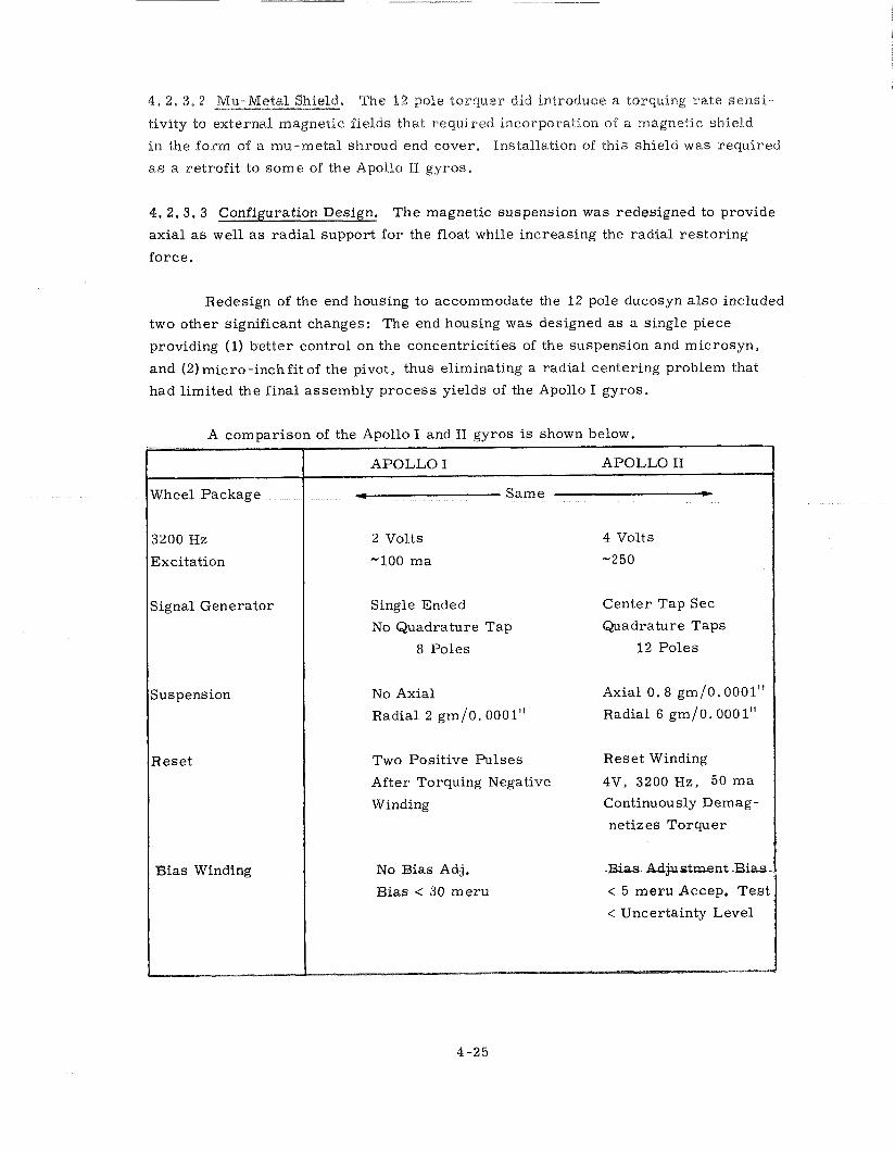
4 , 2, 3 .2 Mu-Metal Shield, The 1 2 pole torquer did introduce a "c~uu ing ra te sens i -
tivity to external magnetic fields that required incorporation of a magnetic shield
in the form of a mu-metal shroud end cover. Installation of this shield was required
as a retrofi t to some of the Apollo I1 gyros.
4. 2.3.3 Configuration Design. The magnetic suspension was redesigned to provide
axia l as well a s radia l support for the float while increasing the radial res tor ing
force .
Redesign of the end housing to accommodate the 12 pole ducosyn a l so included
two other significant changes: The end housing was designed a s a single piece
providing (1) bet ter control on the concentricities of the suspension and microsyn,
and (2) mic ro -inch fi t of the pivot, thus eliminating a radial centering problem that
had l imited the final assembly process yields of the Apollo I gyros.
A comparison of the Apollo I and I1 gyros is shown below.
Signal Generator Single Ended Center Tap Sec No Quadrature Tap Quadrature Taps
8 Poles
Axial 0 . 8 gm/O. 0001"
Radial 2 gm/0.0001" Radial 6 gm/0.000 1"
Two Positive Pulses Reset Winding
After Torquing Negative 4V, 3200 Hz, 50 m a Continuously Demag-
netizes Torquer
No Bias Adj. -Bias Adjustment Bias-
Bias < 30 meru < 5 meru Accep. T e s t
< Uncertainty Level
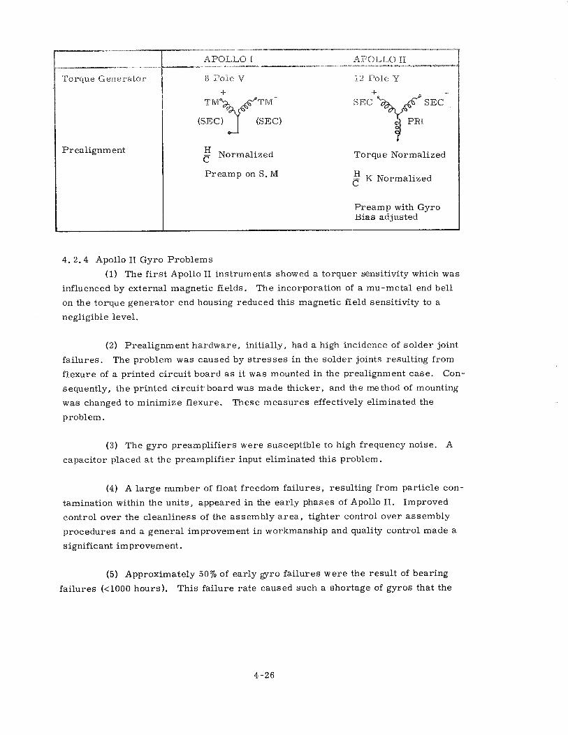
Torque Generator
Pr ealignm ent
8 Pole V 12 Pole Y
Normalized c Torque Normalized
Preamp on S. M K Normalized €
Preamp with Gyro Bias adjusted
4. 2.4 Apollo I1 Gyro Problems
(1) The f i r s t Apollo I1 instruments showed a torquer sensitivity which was
influenced by external magnetic fields. The incorporation of a mu-metal end bell
on the torque generator end housing reduced this magnetic field sensitivity to a
negligible level.
( 2 ) Prealignment hardware , initially, had a high incidence of solder joint
fai lures. The problem was caused by s t r e s s e s in the solder joints resulting from
flexure of a printed circuit board a s i t was mounted i n the prealignment case . Con-
sequently, the printed circuit . board was made thicker, and the method of mounting
was changed to minimize flexure. These measures effectively eliminated the
problem.
(3) The gyro preamplif iers were susceptible to high frequency noise. A
capacitor placed a t the preamplif ier input eliminated this problem.
(4) A l a r g e number of float freedom fa i lures , resulting from part icle con-
tamination within the units , appeared in the ea r ly phases of Apollo 11. Improved
control over the cleanliness of the assembly a r e a , tighter control over assembly
procedures and a genera l improvement i n workmanship and quality control made a
significant improvement.
(5) Approximately 5070 of early gyro fa i lures were the resul t of bearing
fai lures (<I000 hours) . This fai lure r a te caused such a shortage of gyros that the
use of workhorse or norsflight status instruments to cornplete sys tem checkout and
selloff were required, A repa i r program featuring a new bearing design was intro-
duced. However, a s a result of s tar tup delays and somewhat modified manufacturing
procedures, the output of repaired gyros was too low to significantly reduce the
s e v e r e gyro shortage.
The reason f o r bearing failures continues to be under investigation. To
date, however, the principal reason f o r an increased failure r a t e relative to the
Block I bearing has not been discovered. The wheel package was unchanged f rom
that of the Apollo I gyros which exhibited a much better bearing life history.
Various cleaning procedures, lapping methods, and re ta iner redesigns were a t -
tempted without conclusive resul ts (See Section 4.2.7 f o r a more detailed presen-
tation). .
4.2.5 Fai lure Prediction
4.2.5.1 Reliability Test Program. At the s t a r t of Apollo system design, a gyro
reliability t e s t program was initiated. Two a ims of the t e s t program were: ( 1) to
obtain a fai lure model f o r predicting impending system failures, and ( 2 ) t o determine
whether intermittent operation, a s planned f o r the Apollo guidance sys tem to save
power, was any l ess desirable than continuous operation. A total of 10 gyros was
divided into two groups: six were operated continuously fo r 200 hours followed by
se rvo performance f o r 24 hours. F o u r were operated intermittently, i. e . , with
wheels operating fo r 3 hours and off f o r 1 2 hours f o r a total of 210 hours followed
by servo performance f o r 24 hours. Except fo r servo runs, a l l running hours were
accumulated on a torque -to -balance loop. More than 52,000 wheel hours were
accumulated on the 10 gyro units. F o u r wheel bearing failures occurred during
the accumulated running time.
Figure 4-11 compares the acceleration sensitive drif t about the input axis
(ADIA) data f o r units that were run continuously with units that were run intermit-
tently. F o r the s a m e operating t ime, the intermittently operated units resulted in
the more stable performance. Therefore, the intermittent mode of operation in
the sys tem did not result in a performance penalty. There were no differences in
the BD and ADSRA t e r m s f o r the two modes of operation.
4.2.5.2 Data Flow. Data on a l l the significant parameters of gyro performance
were collected f o r a l l units f rom the f i r s t component t e s t s through a l l ISS and
G& N tests. These data were evaluated and formed the basis f o r fai lure prediction.
Moreover, procedure was established fo r centralized assessment of a l l gyro and
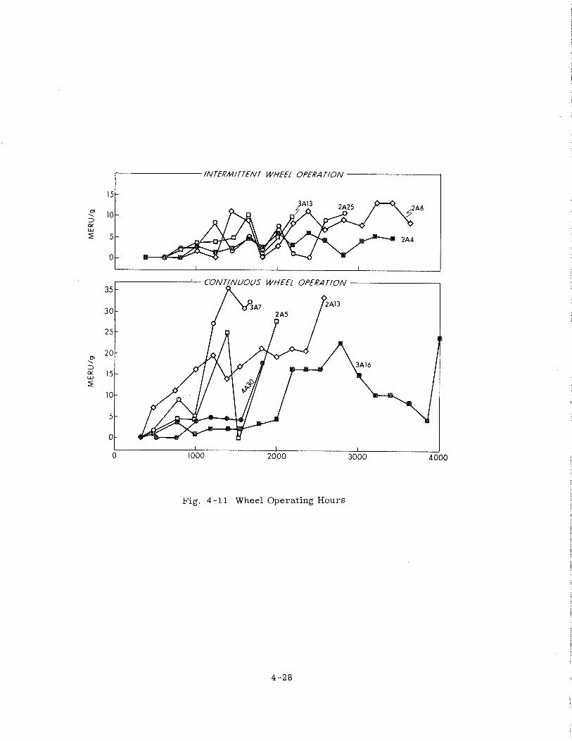
INTERMITTENT WHEEL OPERATION I
Fig. 4 - 11 Wheel Operating Hours
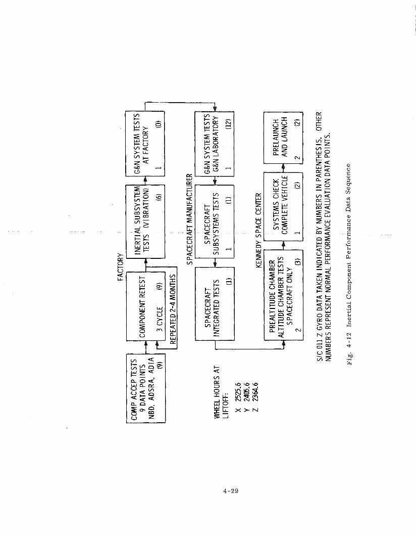
FACT
ORY
9 DA
TA P
OIN
TS
COM
PONE
NT R
ETES
T
I REP
EATE
D 2-
4 M
ONT
HS
I I
G&N
SYS
TEM
TES
TS
WHE
EL H
OUR
S AT
IN
TEGR
ATED
TES
TS
SUBS
YSTE
MS
TEST
S G
&N L
ABO
RATO
RY
L I FT
OFF:
X 25
25.6
KENN
EDY
SPAC
E CE
NTER
PREA
LTIT
UDE
CHAM
BER
ALTI
TUDE
CHA
MBE
R TE
STS
SYST
EMS
CHEC
K
SPAC
ECRA
FT O
NLY
COM
PLET
E VE
H I C
LE
SIC
011
Z G
YRO
DAT
A TA
KEN
IND
ICAT
ED B
Y NU
MBE
RS I
N P
AREN
THES
IS.
OTHE
R NU
MBE
RS R
EPRE
SENT
NO
RM
AL P
ERFO
RMAN
CE E
VALU
ATIO
N D
ATA
PO I N
TS.
Fig
. 4
- 12
In
ert
ial
Co
mp
on
ent
Pe
rfo
rma
nc
e D
ata
Seq
uen
ce
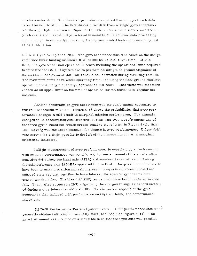
accelerometer data. The checkout procedu-res required that a copy of each data
record b e sent to MIT. The flow diagram for data from a single gyro acceptance
t e s t through flight i s shown in Figure 4-12. The collected data were converted to
punch c a r d s and magnetic tape in formats suitable for electronic data processing
and printing. Additionally, a monthly l is t ing was printed both as a n inventory and
a s data tabulation.
4 .2 .5 .3 Gyro Acceptance Plan. The gyro acceptance plan was based on the design-
reference lunar landing mission (DRM) of 200 hours total flight t ime. Of this
t ime, the gyro wheel was operated 20 hours including the operational t ime required
to initialize the GN & C system and to perform a n inflight o r ground alignment of
the iner t ia l measurement unit (IMU) and, a lso , operation during thrusting periods.
The maximum cumulative wheel operating t ime, including the final ground checkout
operation and a margin of safety, approached 300 hours. This value was therefore
chosen a s a n upper l imi t on the t ime of operation fo r maintenance of angular mo-
m entum.
Another constraint on gyro acceptance was the performance necessary to
insure a successful mission. Figure 4-13 shows the probabilities that gyro pe r -
formance changes would result in marginal mission performance. F o r example,
changes in IA accelerat ion sensit ive drift of l e s s than 1000 meru/g among any of
the th ree gyros would not c rea te e r r o r s equal to those l is ted in Figure 4-13, thus
1000 meru/g was the upper boundary for change i n gyro performance. Unless drif t
r a t e curves for a flight gyro l i e to the lef t of the appropriate curve, a marginal
mission i s indicated.
Inflight measurement of gyro performance, to corre la te gyro performance
with miss ion performance, was considered, but measurement of the accelerat ion
sensit ive drif t along the input axis (ADIA) and accelerat ion sensitive drif t along
the spin reference axis (ADSRA) appeared impractical . One possible method would
have been to make a position and velocity e r r o r comparison between ground and
onboard s ta te vectors , and then to have inferred the specific gyro t e r m s that
caused the deviation. The bias drift (BD) t e r m s could have been measured in f r e e
fall. Then, af ter successive IMU alignment, the changes in angular e r r o r s measur -
ed during a t ime interval would yield BD. Two important aspects of the gyro
acceptance plan included drift performance and system tes t s , and performance
indicators.
(1) Drift Performance T e s t s & System Tes t s - - Drift performance data were
generally obtained utilizing an inertially stabilized loop (See Figure 4-14). The
gyro instrument was mounted on a tes t table such that the input axis was parallel
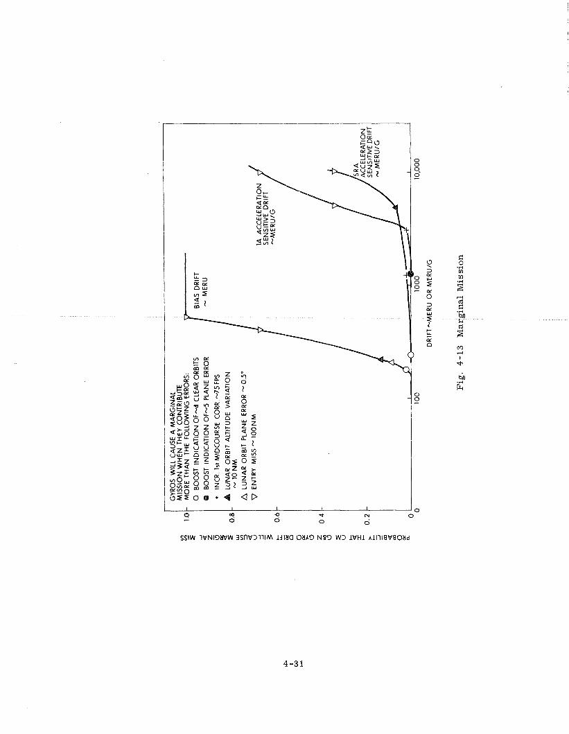
GYR
OS
WIL
L C
AU
SE A
MA
RG
INA
L M
ISS
ION
WH
EN
TH
EY
CO
NTR
IBU
TE
- M
OR
E T
HA
N T
HE
FOLL
OW
ING
ER
RO
RS:
0
BO
OST
IN
DIC
AT
ION
OF-
4 CL
EAR
OR
BIT
S
@
BO
OST
IN
DIC
AT
ION
OF
4 P
LAN
E ER
ROR
+
INC
R. 1
st M
IDC
OU
RS
E C
0RR
.-75F
PS
LUN
AR
OR
BIT
ALT
ITU
DE
VA
RIA
TIO
N
- - 10
NM
A L
UN
AR
OR
BIT
PLA
NE
ERRO
R - 0
.5"
BIA
S D
RIF
T M
ER
U
I- DR
IFT-
ME
RU
O
R M
ER
U/G
Fig
. 4 -
13
M
arg
inal
Mis
sio
n
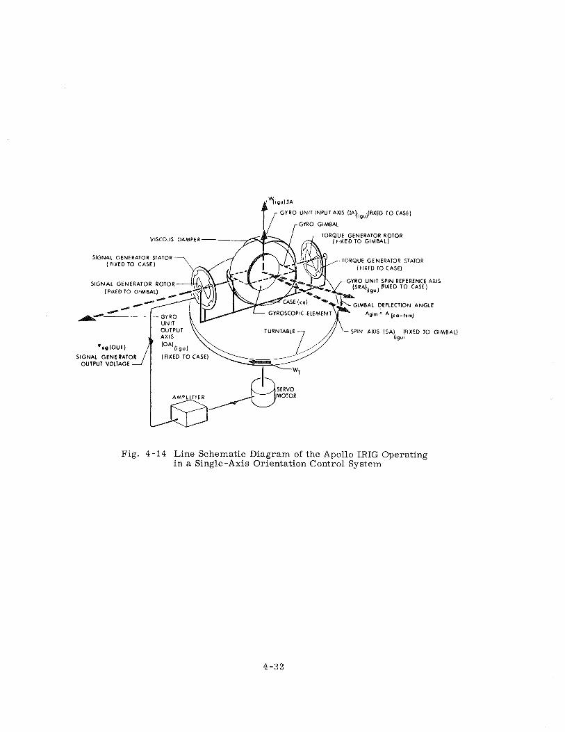
YI~UIIA GYRO UNIT INPUT AXlS (LA),,gU)(FIXED TO CASE) / ,-GYRO GIMBAL
VISCOUS DAMPER TORQUE GENERATOR ROTOR
(FIXED TO GIMBAL)
SIGNAL GENERATOR STATOR ( FIXED TO CASE)
TORQUE GENERATOR STATOR (FIXED TO CASE)
SIGNAL GENERATOR ROTOR 0 UNIT SPIN REFERENCE AXIS RA),,gu) f1XED TO CASE)
(FIXED TO GIMBAL)
IMBAL DEFLECTION ANGLE
Aglm ' A [ca-tsml
-SPIN AXlS (SA) (FIXED TO GIMBAL) Cg"'
Fig. 4-14 L i n e Schematic Diagram of the Apollo IRIG Operating in a Sing le -Axis Orientat ion Control System
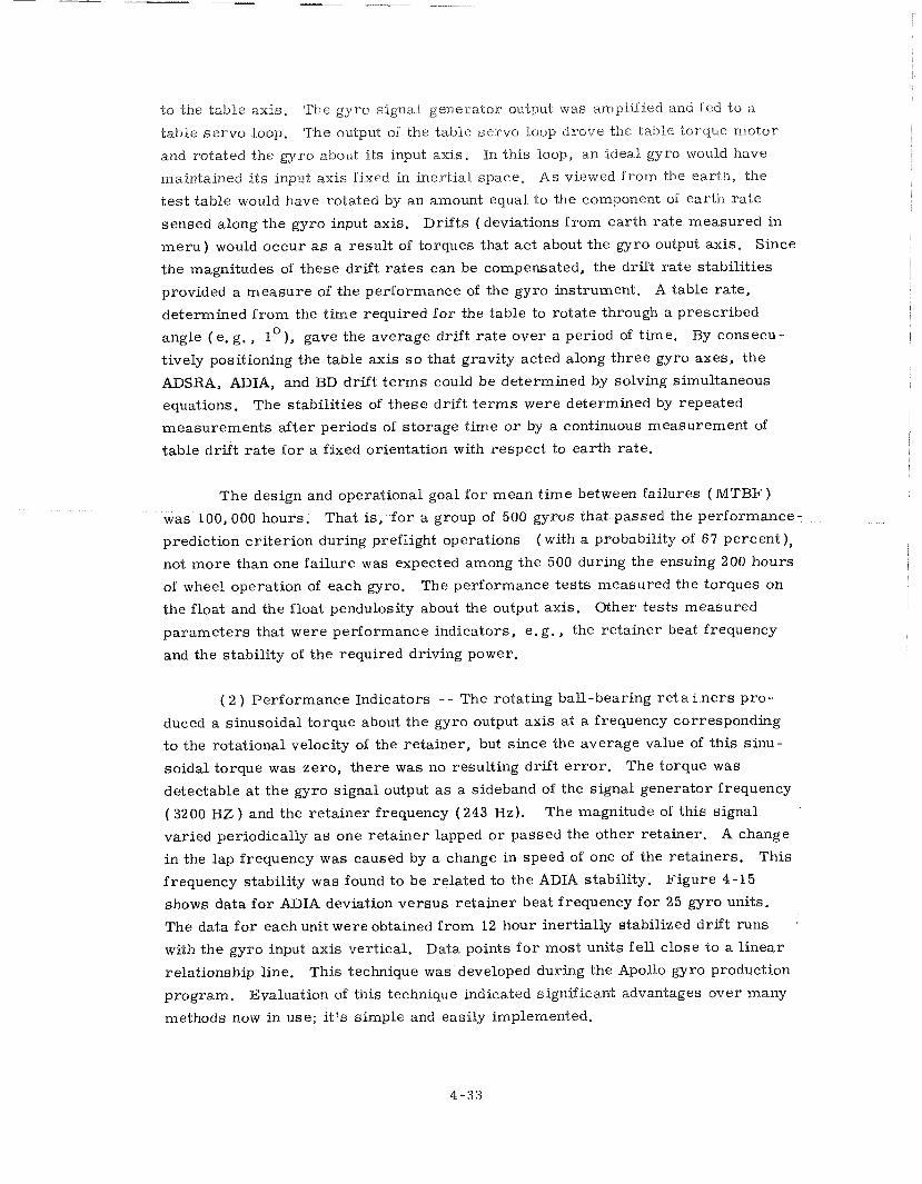
to the table axis. The gyro signal generator output was amplified and fed Lo a.
table s e r v o loop. The output of the table servo loop drove the table torque motor
and rotated the gyro about i ts input axis. In this loop, an ideal gyro would have
maintained i t s input axis fixed m inert ial space. As viewed f rom the earth, the
t e s t table would have rotated by an amount equal to the component of earth ra te
sensed along the gyro input axis. Dri f ts (deviations f rom ear th ra te measured in
m e r u ) would occur a s a result of torques that ac t about the gyro output axis. Since
the magnitudes of these drift r a t e s can be compensated, the drift r a te stabilities
provided a measure of the performance of the gyro instrument. A table rate,
determined f r o m the t ime required f o r the table to rotate through a prescribed 0 angle ( e , g . , 1 ), gave the average drift r a t e over a period of time. By consecu-
tively positioning the table axis s o that gravity acted along th ree gyro axes, the
ADSRA, ADIA, and BD drift t e r m s could be determined by solving simultaneous
equations. The stabilities of these drift t e r m s were determined by repeated
measurements af ter periods of s torage t ime o r by a continuous measurement of
table drif t r a t e f o r a fixed orientation with respect to earth rate.
The design and operational goal for mean t ime between failures ( M T B F )
was 100,000 hours. That is, f o r a group of 500 gyros that passed the performance-
prediction cr i ter ion during preflight operations ( with a probability of 67 percent ),
not more than one failure was expected among the 500 during the ensuing 200 hours
of wheel operation of each gyro. The performance tes ts measured the torques on
the float and the float pendulosity about the output axis. Other tests measured
parameters that were performance indicators, e. g . , the retainer beat frequency
and the stability of the required driving power.
( 2 ) Performance Indicators - - The rotating ball-bearing re t a i .ners p ro-
duced a sinusoidal torque about the gyro output axis a t a frequency corresponding
t o the rotational velocity of the retainer, but since the average value of this s inu-
soidal torque was zero , there was no resulting drift e r r o r . The torque was
detectable a t the gyro signal output a s a sideband of the signal generator frequency
( 3200 HZ ) and the re ta iner frequency ( 243 Hz). The magnitude of this signal
varied periodically a s one re ta iner lapped o r passed the other retainer. A chm-ge
in the lap frequency was caused by a change in speed of one of the retainers. This
frequency stability was found to be related to the ADLA stability. Figure 4-15
shows data fo r ADIA deviation versus re ta iner beat frequency for 25 gyro units.
The data f o r each unit were obtained f rom 12 hour inertially stabilized drif t runs
with the gyro input axis vertical. Data points f o r most units fel l close to a l inear
relationship line. This technique was'developed during the Apollo gyro production
program. Evaluation of this technique indicated significant advantages over many
methods now in use; i t ' s s imple and easily implemented.
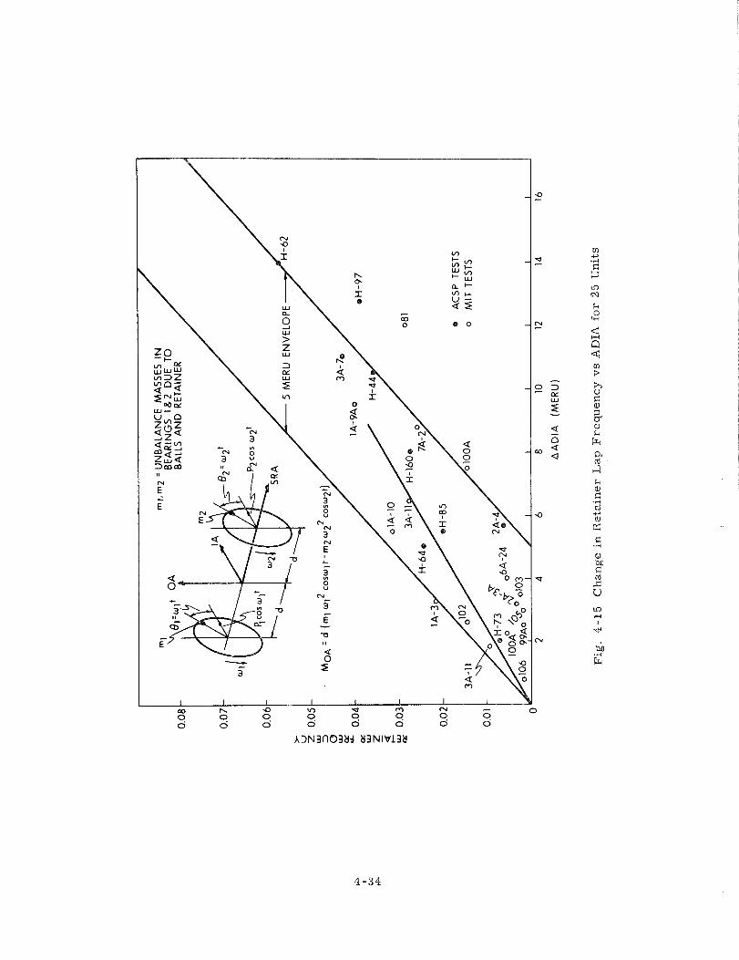
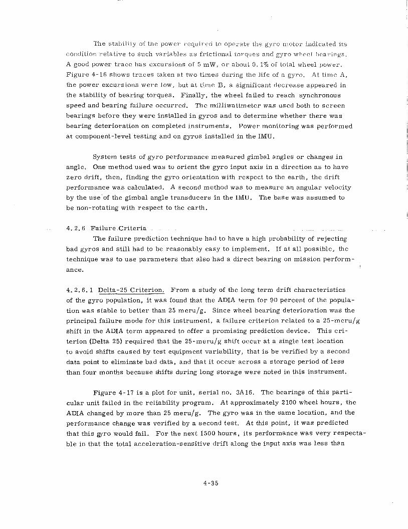
The stability of the power required to operate tile gyro rnotor indicated i ts
condition relat ive to such variables a s frictional torques and gyro wheel bearings.
A good power t r a c e has excursions of 5 m W , o r about 0. 17'0 of total wheel power.
Figure 4-16 shows t r aces taken at two t imes during the life of a gyro. At t ime A,
the power excursions were low, but a t t ime B, a significant decrease appeared in
the stability of bearing torques. Finally, the wheel failed to reach synchronous
speed and bearing fa i lure occurred. The mill iwattmeter was used both to s c r e e n
bearings before they were installed i n gyros and to determine whether there was
bearing deterioration on completed instruments. Power monitoring was performed
a t component-level testing and on gyros installed in the IMU.
System tes t s of gyro performance measured gimbal angles o r changes i n
angle. One method used was to orient the gyro input axis i n a direction a s to have
z e r o drift, then, finding the gyro orientation with respect to the earth, the drif t
performance was calculated. A second method was to measure an angular velocity
by the use 'of the gimbal angle t ransducers in the IMU. The base was assumed to
be non-rotating with respect to the earth.
4. 2.6 Fai lure Cr i t e r i a
The fa i lure prediction technique had to have a high probability of rejecting
bad gyros and s t i l l had to be reasonably easy to implement. If a t a l l possible, the
technique was to use parameters that a lso had a direct bearing on mission perform-
ance.
4. 2. 6. 1 Delta-25 Criterion. From a study of the long term drift character is t ics
of the gyro population, i t was found that the ADIA term fo r 90 percent of the popula-
tion was stable to bet ter than 25 meru/g. Since wheel bearing deterioration was the
principal fai lure mode fo r this instrument, a fai lure cri terion related to a 25-meru/g
shift in the ADIA t e r m appeared to offer a promising prediction device. This c r i -
te r ion (Delta 25) required that the 25-meru/g shift occur a t a single t e s t location
to avoid shifts caused by tes t equipment variability, that is be verified by a second
data point to eliminate bad data, and that i t occur ac ross a s torage period of l e s s
than four months because &ifts during long s torage were noted in this instrument.
Figure 4-17 is a plot for unit, s e r i a l no. 3A16. The bearings of this part i-
cular unit failed i n the reliability program. At approximately 2 100 wheel hours , the
ADIA changed by m o r e than 25 meru/g. The gyro was in the s a m e location, and the
performance change was verified by a second tes t . At this point, i t was predicted
that this gyro would fail. F o r the next 1500 hours , i t s performance was very respecta-
ble in that the total acceleration-sensitive drif t along the input axis was l e s s than
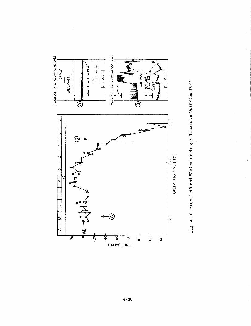
OP
ER
ATIN
G T
IME
(H
RS
)
NM
AY
64
- 67
0 O
PE
RA
TIN
G H
RS
-1 M
ILL1
WA
TT
u
BD
EC
64
- 4
42
5 O
PE
RA
TIN
G H
RS
I A
I
Fig
. 4
-16
A
DL
A D
rift
and W
att
mete
r S
am
ple
Tra
ce
s v
s O
pera
tin
g T
ime
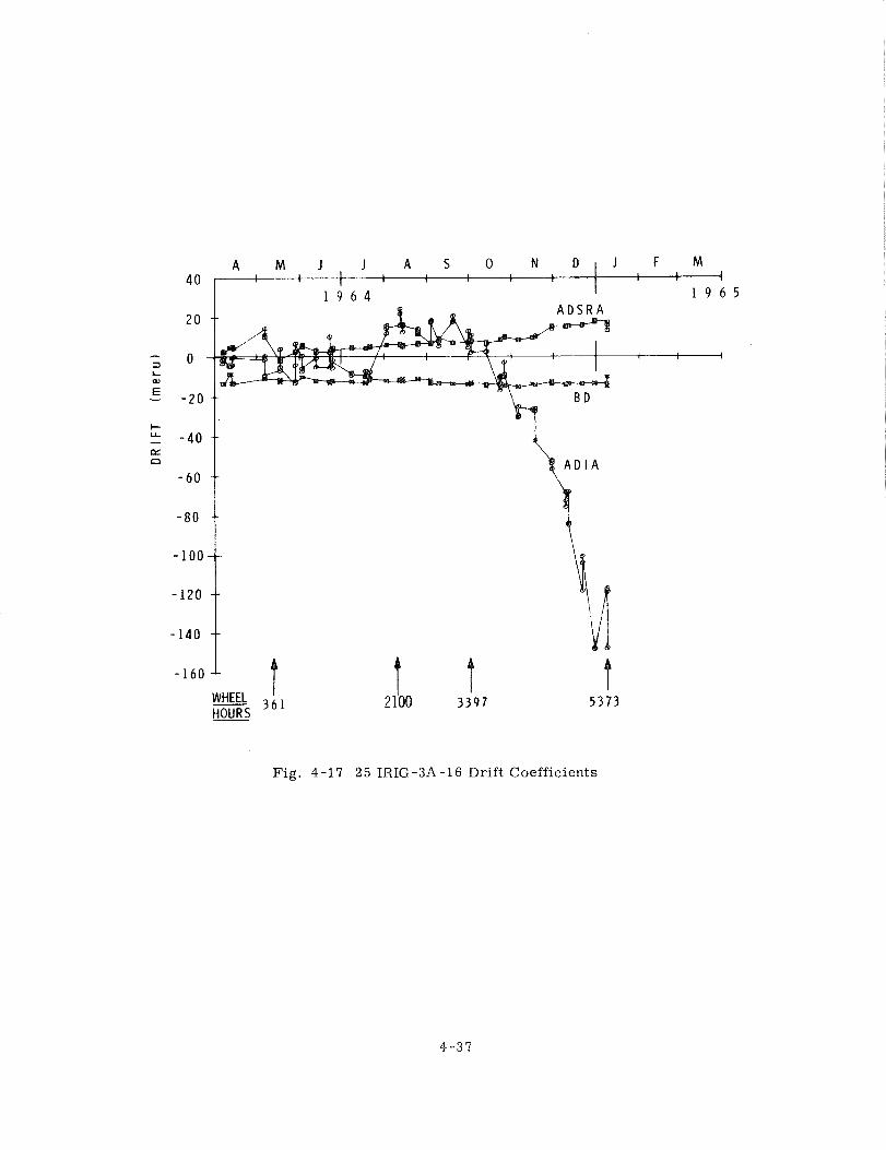
I 3 6 1
HOURS
Fig. 4-17 25 IRIG-3A-16 Drift Coefficients
30 meru/g . At about 3600 hours, the ADIA changed by more than 25 meru /g , and
af ter another 1800 wheel hours the gyro failed completely. After each Delta-25
indication, the total change in ADLA f o r the ensuing 300 hours was l e s s than 2 8 meru/g ,
providing a long lead t ime before the unit failed. During this lead t ime, gyro p e r -
formance was s t i l l suitable fo r an Apollo mission. Note that the bias drif t ( BD ) was
very stable, and the acceleration-sensitive drif t along the spin-reference axis
(ADSRA) changed very slowly during the life of this gyro. Small o r gradual changes
in BD and ADSRA were character is t ic f o r a l l wheels that failed,
Figure 4-18 is a n example of prediction of system performance f o r a gyro
installed in the guidance system. The ADSRA t e r m changed by m o r e than 25 meru /g
at the t ime of installation into the system. Subsequent t e s t s verified th is change.
The Delta-25 cr i ter ion would not have picked up this pa ramete r on that instrument
s ince i t changed location. After installation in the system, a subsequent ADIA
change of more than 25 meru /g occurred and was verified. Upon this indication of
a potential fa i lure , the gyro was removed f r o m the guidance sys tem and was tested
until the wheel failed. The wheel t ime accumulated af ter the Delta-25 cr i ter ion was
equivalent to 80 lunar missions. Again, the BD and ADSRA t e r m s remained stable
until the gyro failed completely.
The Delta-25 cr i ter ion is now used f o r a l l gyros. To implement its use fully,
the performance of each gyro was measured periodically. Units that exceeded the
cr i ter ion were either removed a s fa i lures f r o m the sys tem to be verified o r were
requalified. The requalification t es t was a re run of the unit acceptance test .
4.2.6.2 The F Cr i t e r ion . Since the re was a correlation between ADIA instability
and impending wheel fai lure, any parameter that measured ADIA stability could have
provided a basis f o r fa i lure prediction. There were th ree c r i t e r i a that could be
applied: ( 1 ) a magnitude change in ADIA exceeding some level, e . g . , the Delta-25
cri terion; ( 2 ) the standard deviation of the ADIA exceeding some level; and ( 3 )
the exceeding of some level by the r m s value of successive ADIA differences ( r m s s d ) .
All of these methods were found to obtain large magnitudes for a situation that oc-
curred frequently but was not an incipient fai lure. F o r example, a change in drift
could have occurred f r o m dimensional changes in the float s t ructure , with the drift
then becoming stable at a new level. It was difficult t o find a standard magnitude-
or-deviation cr i ter ion that would account f o r a stable level change. The F cri terion,
however, which was based on method 3 , served this purpose. By the F cri terion,
a fai lure was predicted if the rrnssd of the las t 11. ADIA data points exceeded
10 meru/g . A unit requalified if its rmssd l a t e r dropped below 10 meru /g . The r e -
qualification indicated a unit that shifted in A D U dr i f t but was l a te r stabilized. The
r m s s d was defined by the following equation:
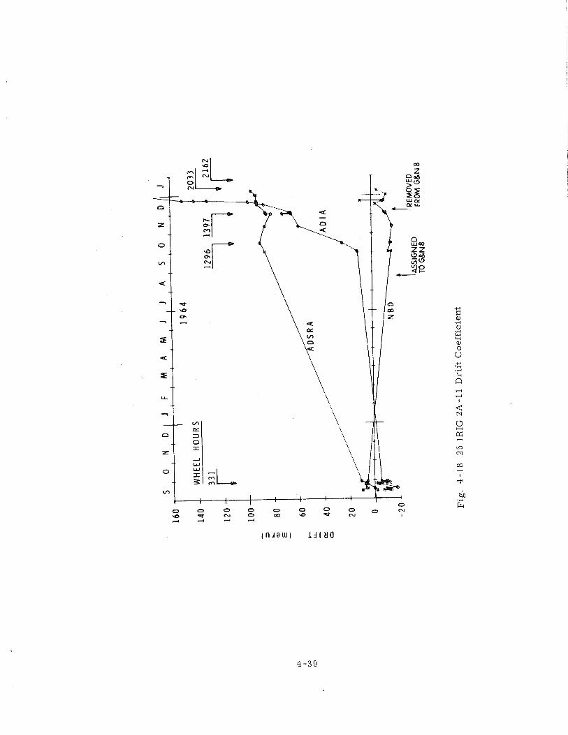
where x. was the present value of ADIA, and N was 11 f o r the F cri terion. 1
Figure 4-19 shows rmssd versus wheel hours f o r unit 2A5, which exceeded
the F cri terion at 1500 wheel hours. 500 hours l a te r i t failed to s t a r t a t the appli-
cation of wheel voltage. These hours would have been sufficient t ime t o complete
two preflight t e s t s and missions. Gyro 2 A l l (F ig . 4-20) exceeded the F cri terion
during acceptance test ing ( 300 wheel hours ), l a t e r was requalified, then exceeded
the F cri terion again a t 1200 hours. It had stable ADSRA and BD performance even
af ter it had exceeded the F cr i ter ion f o r ADIA data. It was run intermittently f o r
another 800 hours before fai lure; again, the re was adequate warning to have allowed
a successful completion of the mission.
4.2.6.3 Usefulness and Efficiency Indices fo r the Criterion. Usefulness and efficiency - -- indices a r e defined in F igure 4 -21. The usefulness of a fai lure -prediction method
was considered a s the percentage of gyros that were predicted good and, in fact,
remained good. The efficiency of the prediction technique rested in the percentage
of gyros not rejected. F o r example, if 5 percent of the good gyros had been rejected,
prediction efficiency would have been 95 percent. F o r the Delta-25 cri terion, the
calculated usefulness indices f o r the Apollo Block I and Block I1 gyros were 99 and
98 percent, respectively. The efficiency indices were 89 and 98 percent.
F o r the F cri terion, a l l but one of the Apollo Block I bearing failures were
predicted. However, 23 units were predicted to fa i l but did not. This yielded a use -
fulness index of 99 percent and an efficiency index of 80 percent. F o r Block 11, the
F cr i ter ion 's usefulness index was 99 percent and i t s efficiency index was 96 percent.
4.2.6.4 Fai lure Cr i t e r i a Summary. -- Fai lures were grouped into major categories and
were a s follows:
( 1 ) Bearing Fa i lu res - - This group contained non-start wheel units with
ADIA instability, decreasing wheel run-down time, and e r ra t i c wattmeter data in-
dicating a n impending wheel fai lure. The group a lso included units that failed from
other causes, such a s contamination, that is, when fa i lure analysis showed the
wheel bearings to be badly deteriorated and imminently susceptible to fai lure from
this cause.
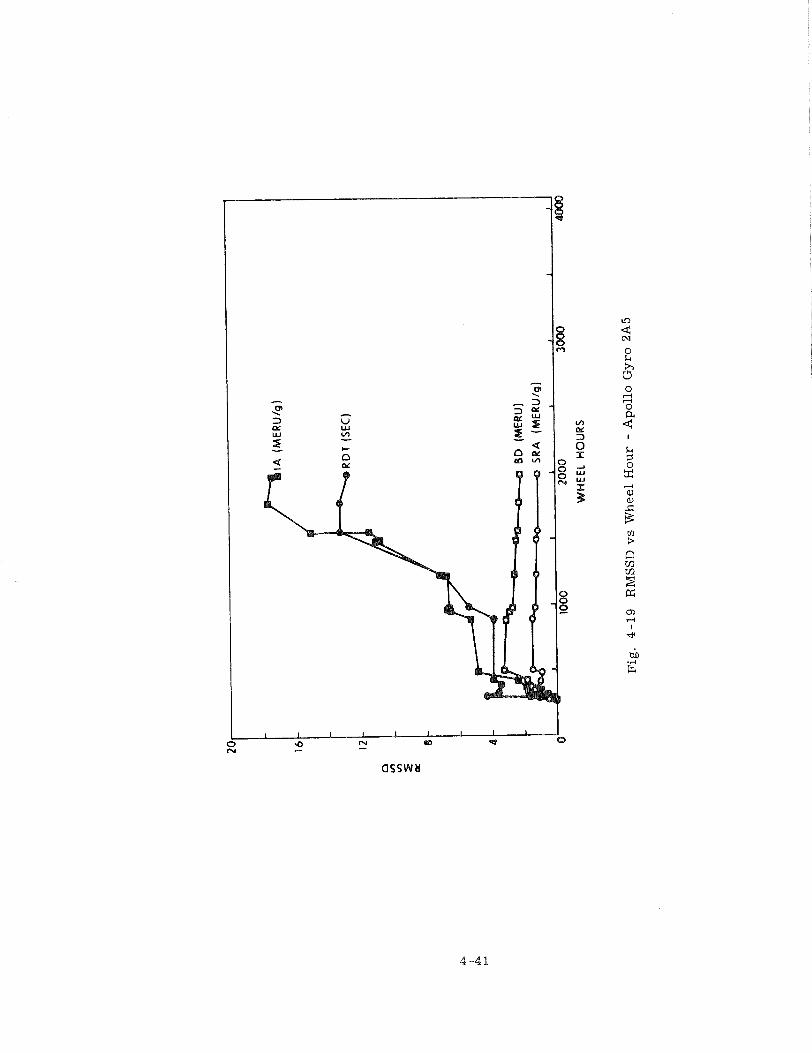
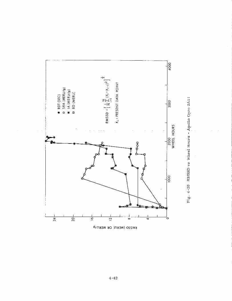
I R
DT
(SE
C)
0
SR
A (
ME
RU
/g)
IA (
ME
RU
/g)
b D
B
D (
ME
RU
)
WH
EE
L H
OU
RS
Fig. 4-20 RMSSD vs Wheel H
ou
rs -
Apollo Gyro 2All
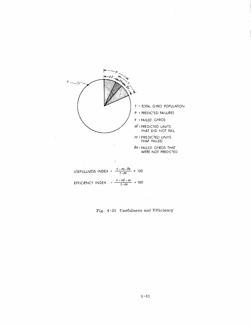
T
T = TOTAL GYRO POPULATION
\ / P = PREDICTED FAILURES
\ / F = FAILED GYROS
PF = PREDICTED UNITS THAT DID NOT FAIL
PF = PREDICTED UNITS THAT FAILED
FF = FAILED GYROS THAT WERE NOT PREDICTED
USEFULLNESS INDEX = ;!:;" x 100
EFFICIENCY INDEX = T - PF - PF
T - PF
Fig. 4 - 2 1 Usefulness and Efficiency
( 2 ) Float-Freedom Fai lures - - This group contained instruments failing the
float -freedom tes t . This t e s t identified units containing foreign fluids o r particulate
mat ter in the damping fluid. Most units, which had been identified f o r the repa i r
program as Category a11 repairs , evidenced this problem. Other i tems in Category
III were gyro flexlead and ducosyns, i. e. , problems associated with the internal
gyro but not with the bearings and internal float assembly.
( 3 ) Flex-lead Fa i lu res on Centrifuge Testing - - This group consisted of two
units that had failed during centrifuge testing a t NASA/ MSC. Fai lure analysis had
indicated an open wheel lead. Because of this environment testing, these units were
not candidates f o r repair .
( 4 ) Elect r ica l Fa i lu res - - This group included typical shor t s o r opens in the
gyro external electrical circuitry and prealignment components. It represented a l l
units grouped in the repa i r program a s Category I1 repairs .
( 5 ) Delta-25 Predicted Fa i lu res - - This group consisted of units predicted
to fa i l by the Delta-25 fa i lure cri terion, i. e . , a gyro exhibiting a shift in drift t e r m s
of m o r e than 25 meru /g was suspect and subjected to fu r the r testing and analysis
before being committed t o flight. The cri terion was qualified in that only shifts of
25 meru /g o r m o r e occurring a t a single t e s t location were considered. Shifts had
to be verified by a second datum point, and must have occurred a c r o s s a s torage
period of l e s s than four months. The single t e s t location minimized any data shifts
caused by t es t equipment variability. The verification by a second datum point was
necessary t o eliminate the likelihood of bad data. The restr ict ion of the storage
period between tes t s limited the storage-sensit ive shifts that were noted in th is in-
strument.
4 .2 .7 Fa i lu re & Reliability Summary
The Apollo I gyros were subdivided during manufacture into five groups ac -
cording t o the date of manufacture. Most of the discrepancies in drawings and
procedures were corrected during the construction of the first two groups. The
failure r a t e fo r each failure cause was plotted f o r each group ( s e e Figure 4-22 ).
Induced failures were not included a s fai lures in this plot. The l a rge number of
fai lures, 73 percent in Group I, was attributed to the changes required and to s t a r t -
up problems. Groups I1 to IV show a continuing improvement in the percentage of
fa i lures , a low of 13 percent f o r Group IV. Figure 4-23,a plot of the average wheel
hours f o r each group, shows that the average operating hours f o r the last four groups
had decreased slightly. This could partly explain the decreasing number of fai lures
fo r Groups 111 and IV and should have resulted in fewer fa i lures f o r Group V.
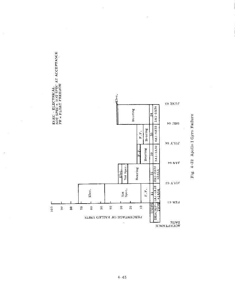
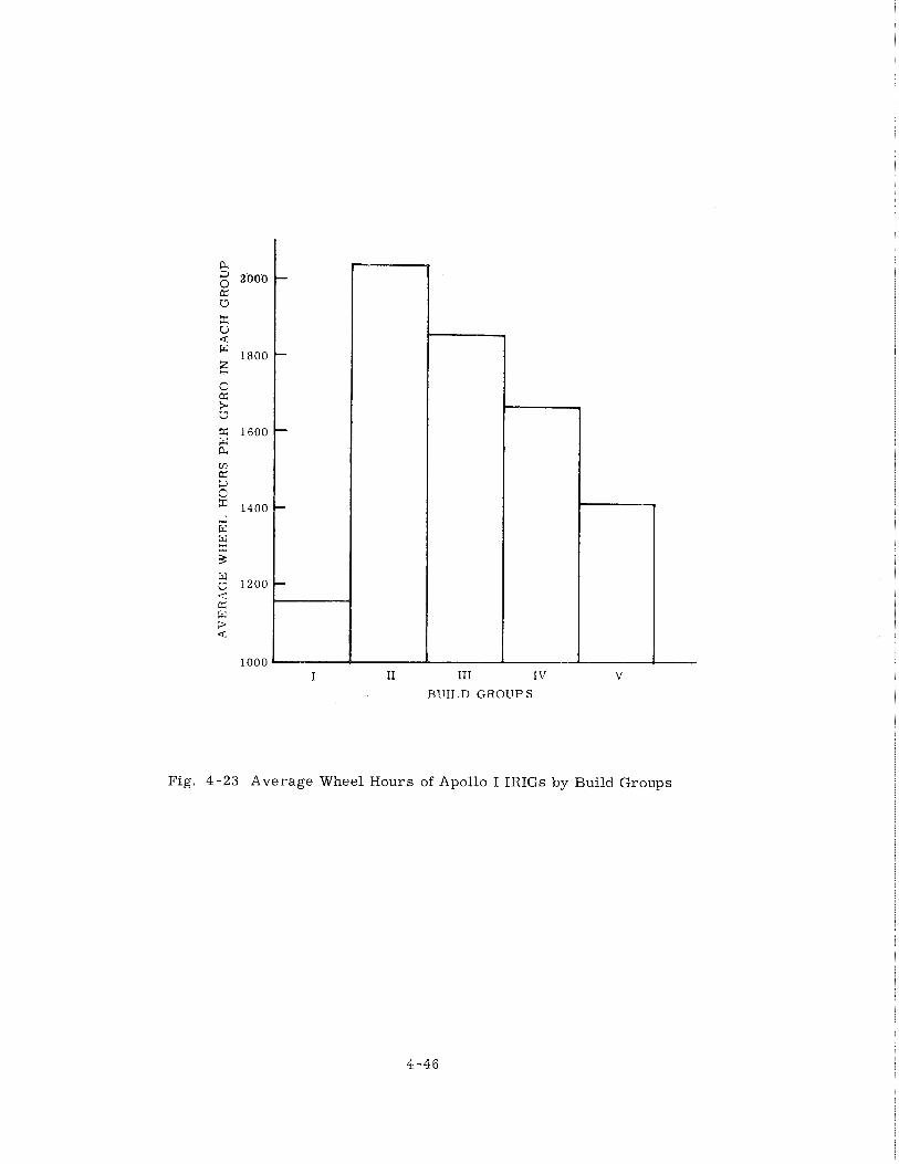
I I1 I11 IV v B U I L D G R O U P S
Fig. 4-23 Average Wheel Hours of Apollo I IRIGs by Build Groups
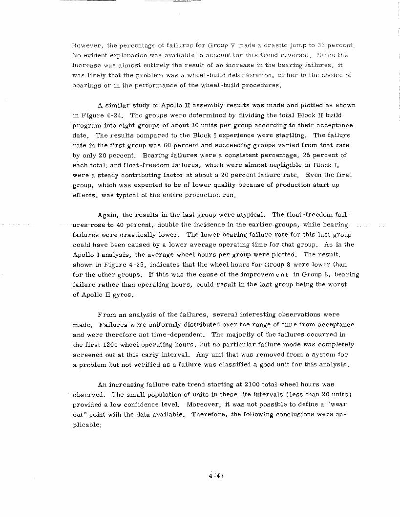
However, the percentage of fa i lu res f o r Group V made a dras t ic jump to 33 percent,
No evident explanation was available to account fo r this trend reversal . Since the
increase was almost entirely the result of an increase in the bearing failures, it
was likely that the problem was a wheel-build deterioration, ei ther in the choice of
bearings o r in the performance of the wheel-build procedures.
A s imi la r study of Apollo I1 assembly resul ts was made and plotted a s shown
in Figure 4-24. The groups were determined by dividing the total Block I1 build
program into eight groups of about 30 units pe r group according t o the i r acceptance
date. The resul ts compared t o the Block I experience were start l ing. The fa i lure
r a t e in the first group was 60 percent and succeeding groups varied f rom that r a t e
by only 20 percent. Bearing fa i lures were a consistent percentage, 25 percent of
each total; and float-freedom failures, which were almost negligible in Block I,
were a steady contributing factor a t about a 20 percent fai lure ra te . Even the first
group, which was expected to be of lower quality because of production s t a r t up
effects, was typical of the entire production run.
Again, the resul ts in the last group were atypical. The float-freedom fail-
u r e s r o s e to 40 percent, double the incidence in the ea r l i e r groups, while bearing
fa i lures were drastically lower. The lower bearing fa i lure ra te for this l a s t group
could have been caused by a lower average operating t ime f o r that group. As in the
Apollo I analysis, the average wheel hours p e r group were plotted. The resul t ,
shown in Figure 4-25, indicates that the wheel hours f o r Group 8 were lower than
f o r the other groups. If th is was the cause of the improvem e n t in Group 8, bearing
fa i lure ra the r than operating hours, could result in the las t group being the worst
of Apollo I1 gyros.
F r o m an analysis of the fa i lures , several interesting observations were
made. Fa i lu res were uniformly distributed over the range of t ime f r o m acceptance
and were therefore not time-dependent. The majority of the fa i lures occurred in
the f i r s t 1200 wheel operating hours, but no part icular fai lure mode was completely
screened out a t this ear ly interval. Any unit that was removed f rom a sys tem f o r
a problem but not verified a s a fa i lure was classified a good unit f o r this analysis.
An increasing failure r a t e trend start ing a t 2100 total wheel hours was
observed. The smal l population of units in these life intervals ( l e s s than 20 units )
provided a low confidence level. Moreover, it was not possible to define a "wear
out" point with the data available. Therefore, the following conclusions were ap-
plicable:
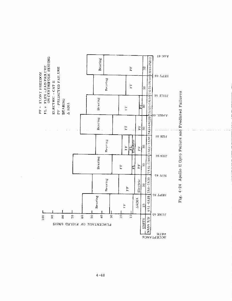
FF =
F
LO
AT
FR
EE
DO
M
F'L
F
FL
EX
LE
AD
FA
ILL
'RE
O
N C
EN
TR
IFU
GE
TE
ST
ING
EL
EC
TR
IC -
CA
T I
1
PF
= P
RE
DIC
TE
D F
AIL
UR
E
BE
AR
ING
A A
DIA
Fig
. 4
-24
A
po
llo
I1
Gy
ro F
ail
ure
an
d P
red
icte
d F
ail
ure
s
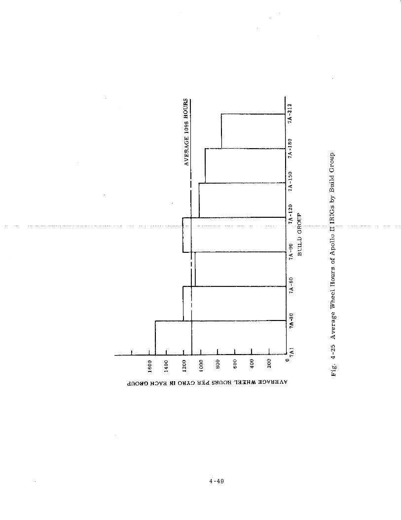
AVERAGEWHEELHOURSPERGYROINEACHGROUP
rt- F I-
EirPWONAo, 00000000
0 00000000
( 1 ) The failure r a t e p e r wheel Life was consistent a t 20 percent p e r 300
wheel hours and a t 14 percent per 5 months. The difference in these two failure
ra tes indicated that the gyro population was not being subjected to an average a c -
cumulation of 300 hours over five month intervals.
( 2 ) Sixty-nine percent of the fai lures were identified in the f i r s t 1200 wheel
hours af ter assembly. This was the resul t of classifying a l l Apollo I1 units soon
af ter acceptance a s e i ther potential fai lures o r flight-quality units. F o r these units,
a longer acceptance cycle ( 1200 wheel hours ) would have been very effective in
screening a majori ty of the fai lures.
( 3 ) It was estimated that 14 failures would have occurred if a l l the Apollo I1
gyros were operated an additional 300 hours, and 12 of those fa i lures would have
occurred in the ensuing five months.
( 4 ) Inasmuch a s catastrophic fa i lures resulting f rom poor solder connections
o r contaminant in the damping fluid could not have been predicted, such fa i lure modes
were eliminated o r held very low.
Although the remaining failure mechanisms f o r the Apollo gyro were quite
complex, the reliability study program yielded two useful c r i t e r i a f o r the pr imary
failure mode o r wheel fai lure. The Delta-25 fa i lure cri terion was not 100 percent
effective because it predicted failure f o r some units that were not about to fa i l and,
conversely, it missed s o m e that did fail. Fur the r , i t required elimination of data
that occurred ac ross location changes, even though data were shown to corre la te
very well at all locations. As more data were accumulated, more refined prediction
c r i t e r i a were established. The F cri terion was one SUCH promising refinement.
Indices both of its usefulness and efficiency were high for the Apollo Block I1 gyros,
and it was e a s i e r t o apply than was the Delta-25 cri terion, since the F cr i ter ion
could be applied t o a l l t e s t data regardless of s torage period o r of t e s t location
changes. The paramete r monitored both f o r the Delta-25 and the F c r i t e r i a was
ADIA. Neither BD nor ADSRA showed significant changes that could be correlated
with wheel fai lure.
A s of January 1, 1967, 361 production gyros had run a total of 380,77 1 wheel
hours. Excluding the wheel hours on any units af ter fai lures were predicted by the
Delta-25 cri terion, the total wheel operating hours were 346, 175, which yielded
an MTBF of 100,000 hours with 70 percent confidence.
Another analysis of fa i lure data related bearing-failure r a t e as a func t ion
of wheel hours f o r Block L and Block 11. This analysis was aimed at determining
if a wear-out t i m e was evidenced f o r the gyro bearing. A r i s e in the Apolbo I1
bearing-failure r a t e a t about 2100 wheel hours seems to have been indicated, How-
ever , the population was too small , that is, the confiderice level was low a s a
result of the l a rge effect of a single fa i lure in these groups to have allowed this
conclusion. As the population operating hours increased, however, a m o r e defini-
tive conclusion became possible.
One very interesting finding was that the average bearing failure ra te f o r
Apollo 11 was 10.4 percent f o r 300 wheel hours, which was th ree t imes the bearing-
fai lure r a t e fo r Apollo I ( 3 . 1 percent) . The cause of the higher bearing failure
r a t e f o r the Apollo I1 gyro could have only been caused by a change in assembly,
mater ia l lots o r processing, o r quality control monitoring between these two gyros,
s ince the re was no design change to the wheel package between these two instrument
builds. By every failure c r i t e r i a presented, Apollo I gyros operated within accep-
table performance requirements f a r longer than Apollo I1 instruments. The
difference in l ife character is t ics between the two groups had not changed substantially
with usage and the passage of t ime.
There were some assembly and t es t changes that occurred between the
Apollo I and Apollo I1 build effort. It was not possible to t e l l whether any of these
contributed to the poorer reliability obtained f o r Apollo I1 units. However, s o m e
of these differences a r e included here fo r clarification.
( 1 ) The bearings were directly assembled into the float f o r most of the
Apollo II build, whereas the Apollo 1 bearings were f i r s t tested in a dynamometer
and then disassembled, cleaned, inspected, and assembled into the float.
( 2 ) The GSE torque-to-balance loop and ramp generator were changed be-
tween the Apollo I and Apollo 11 build. The quantity of ramps required f o r Apollo I1
float freedom t e s t was decreased f rom that required f o r Apollo I.
( 3 ) There was a significant change in the reliability documentation required
f o r Block II. This configuration required documentation.and traceability fo r each
component in the build. The l a rge documentation requirement may have created a
fa lse sense of secur i ty and resulted in a reduced monitoring effort in the important
a r e a s of assembly and tes t .
( 4 ) The Apollo I: gyro contra-ct changed f rom a cost -plus, fixed-fee basis
in the middle of i t s build to a f ixed-price plus incen"cve f o r the remainder of the
Apollo I build, The Apollo U contract was a cost-plus incentive contract.
( 5 j ApoZlo I was built while the Po1ar. i~ production coiltract was in -house a t
ACE, using the same assembly personnel and a rea . The higher level of available
Navy quality control monitoring may have helped Apollo reliability.
( 6 ) As a resul t of phasing out of Polar is and other programs at ACE, the re
was a reassignment of the assembly and tes t technicians working on the Apollo
program. A higher level of personnel reassignments appeared to have occurred
during the ent i re Apollo 11 program which resulted in a continuous retraining effort .
T h e l a rge Apollo 11 failure r a t e strongly points out the inadequacy of the
acceptance tes t a s a fully effective reliability screen. A more meaningful s e r i e s
of specifications f o r assembly, inspection and t es t to achieve an effective accep-
tance screening, appears t o have been required.
4.3 Power and Servo Assembly (PSA)
4.3. 1 Description
T h e Power and Servo Assembly ( PSA ) comprised the electronics that sup -
ported the operation of the inert ial and optical subsystems and was located in a
common module f o r convenience in packaging and spacecraft installation.
4.3.1.1 Block I PSA. The Block I PSA contained most of the electronics associated
with the iner t ia l subsystem, including the IMU servo electronics, IRIG and PIP
pulse torque electronics, CDU electronics, power supplies, and mode switching
electronics. Some of the ISS electronics were located on the IMU and included IRIG
and PIP microsyn suspension networks, signal generator preamplifiers, t empera -
t u r e control sensors , and resolver adjustment networks. Phase correction capacitors
were located on the CDUs. The Block I PSA also contained most of the electronics
fo r the optical subsystem.
The design of the Block I PSA was influenced largely by the concept of in-
flight malfunction diagnosis and repair . Repair was to be done by direct replacement
of failed subassemblies with on-board spares . The Block I PSA was designed with
this concept as a ground rule. T o this extent, the PSA electronics were packaged
in small , replaceable modules that plugged into a wired t ray. Where possible,
functional subassemblies having similar requirements were packaged as identical
modules. Thus, a l l three IMU gimbal servo amplifiers were packaged as identical
modules, and each contained three values of a feedback element appropriate to the
gain. requirements of the inner, middle, and outer gimbal serovs.
Selection of the proper feedback was effected by tray wiring when the servo
amplifiers were plugged into the inner, middle, o r outer gimbal positions in the
tray. Thus, one spare gimbal servo amplifier could function a s the repair module
for any of the three locations. Similarly, identical 1% and 5% 800 Hz power supplies
were used for the inertial and optical subsystems.
The modules were plugged into ten individual trays and appropriately inter -
connected by t ray wiring. The trays, in turn, were plugged into a tray connector
and interconnect harness assembly for further power and signal interfacing with the
res t of the G & N system and the spacecraft. To aid in inflight malfunction diagnosis,
a connector a t the front of each t ray provided selected test points that were then
available to the inflight monitoring test set. The inflight maintenance concept was
abandoned after the PSA design was released for manufacture and subsequently was
never use
The electrical problems experienced in theBlock I PSA fell into two general
categories: those identified from engineering evaluation and qualification testing and
reliability analysis, and those identified from System Testing. The schedule for
delivery of hardware had not permitted the luxury of an exhaustive evaluation phase
pr ior to manufacturing release. Consequently, designs were being released for
manufacture concurrent with breadboard and engineering evaluation testing. As
circuit parameters became better defined, component values were altered to place
them closer to design centers. Reliability analysis of component failures during
the engineering evaluation and parts qualification phases required replacement of
some components with more reliable ones. These problems were not considered
inherent design deficiencies but reflected a normal refinement of the designs with
the passage of time.
System testing exposed design deficiencies that required PSA modifications.
They a r e listed below:
( 1 ) A filtering o r decoupling capacitor was added to the ADA preamp to pre-
vent the 102.4 Kpps signal of the fail circuit from being coupled into the servo loop.
( 2 ) A parallel diode circuit was added from the summing junction of the
gimbal servo amplifier to complementary side of the input differential amplifier in
order to reduce the gain for large saturable signals at the summing junction. This
modification resulted because a large charge was trapped on a capacitor in the ADA
filter when moding between coarse align and fine align took place.
( 3 ) Capacitors were added to the output stage of the CDU motor drive
amplifier to form a high-frequency break in the response of the amplifier. These
capacitors corrected a problem that had resulted because of variations in the gain-
bandwidth product of the output transistors.
( 4 ) The bandwidth of the demodulator fi l ter in the encoder electronics was
reduced by changing the value of the f i l ter capacitors. This was considered neces - sary to reduce the 6400 pps noise that was being generated by the IMU heater
controls and coupled into the encoder. The bandwidth was reduced to approximately
3400 Hz.
( 5 ) The ternary mode of PIP pulse torquing resulted in intolerable acceler - ometer bias instabilities. The decision to change to binary torquing required a
redesign of much of the PIP electronics.
4.3.1.2 Block I1 and LM PSA. The designs of both PSAs were essentially
the same. Since the LM did not have an optical subsystem that required electronics
within the PSA, the LM PSA was physically smaller. The basic ISS portions of the
CM and LM PSAs were identical, however. The inflight maintenance concept was
dropped for the Block I1 CM and LM. This permitted a more efficient packaging
scheme and allowed fo r hermetic sealing of the PSA. There were, however, certain
calibration modules that were matched to a particular IMU. It was necessary to
open up the PSA and change these modules in the event that an IMU was replaced,
unfortunately with the consequence of compromising the integrity of the PSA hermetic
seal. The decision, therefore, was to incorporate portions of the IRIG and PIP
pulse torque electronics into separate packages. For the LM, the Pulse Torquing
Assembly (PTA) , a s the package was called, was located close to the IMU and ex-
ternal to the cabin, which was physically separated from the PSA by long cable runs.
This location minimized problems associated with long leads. Fo r the CM, the
PIPA Electronics Assembly ( PEA) was located in the space formerly occupied by
the Block I CDUs. The PEA and the PTA were functionally parts of the PSA, but
were packaged separately for operational convenience.
'The Block II and L M BA. electronics were basically the s a m e as Block I.
Changes that were made were to aceommodate wider variations in spacecraft
supplied p r ime power voltage, o r were refinements of the circuitry based on
experience o r the resul t of improved components that became available.
Block I experience showed that the added margin in IMU stablization stability
provided by the IMU Angular Differentiating Accelerometers (ADA) was not r e -
quired. The ADAs and associated electronics were deleted f rom the Block I1
design. The CDU was changed to a n a l l electronic device and packaged separately,
thus removing the CDU electronics f r o m the PSA. The IMU temperature control
was changed f r o m a sophisticated proportional temperature control scheme employing
magnetic ampl i f iers and pulse-width modulation techniques to a much s imple r
thermostatically controlled on-off type. Thus, a l l the temperature control electron-
i c s f rom the PSA were eliminated. As with Block I, functional subassemblies were
packaged a s s m a l l modules that plugged into a prewired PSA header. Where pos-
sible, functionally s imi la r subassemblies were again packaged a s identical modules.
The final Block I1 modules evolved satisfactori ly af ter severa l component value
changes, brought about circuitry optimization. TheBlock I1 PSA encountered few
component -associated problems during the manufacturing period.
Two capacitor fa i lures did occur. One capacitor failed "open" because of
inadequate metallization on the end of the roll . Since only one par t out of 8000 pur - chased exhibited this fai lure mode, it was concluded that nopar t problem was
evidenced by th is one failure. Another capacitor "open" was found to be an inadequate
internal lead solder connection. The vendor instituted corrective action by using a
number of loops f o r the solder termination to replace the single loop of the original
design. A res i s to r fai lure was attributed t o a f rac tu re of the glass subst ra te on
which the res is tance element was formed, After considering the number of devices
used versus the one failure encountered, it was concluded that no par t problem
existed with th is type of component.
Two instances of parts-oriented t rans i s to r fai lures were encountered. F i r s t ,
a gimbal s e r v o exhibited a high offset null during module testing. The cause was
found to be unstable, long t e r m drift character is t ics of the t ransis tor P / N 1010252-1.
The correct ive action was t o add a high temperature bias sc reen t es t requirement
t o the Specification Control Drawing. This screening enhanced the detection of
surface contamination of the part . Two instances of cracked dies were discovered
in t r ans i s to r s of the 800 Hz amplifier. The t rans i s to r s were changed to another
type; no other correct ive action was taken. A design oriented diode problem occur-
r ed when diodes P / N 1010385 were found t o exhibit a lowering of forward breakdown
voltage. This anomaly occurred a s the pa r t s were procured l a te r in the program.
This condition is generally recognized a s an improvement of diode character is t ics ,
but not when used in a voltage-dependent bias circuit such a s was the case. A
change in res i s to r value was incorporated in the design to compensate for the
change in breakdown voltage.
Changes and modifications to the PSA electronics resulted because of sys tem
tes t resul ts , the inability to procure specified par ts over the life of the contract,
and the variation of component pa ramete rs fo r large numbers of components. The
gimbal servo amplifier required a change in output t r ans i s to r s a s a resul t of d i s -
continuance of manufacture of the originally specified part . Feedback diodes of the
se rvo amplifier had to be tightly specified a s the program developed because of
p a r t s pa ramete r variations. A design change was incorporated in the 3200 Hz, 1%
supply t o prevent overshoot of the supply output a t turn-on. System tes t s had shown
the overshoot to be a factor in gaussing of the PIP.
4. 4 Inert ial Measurement Unit ( IMU )
4. 4. 1 Mechanical Design
The IMU consisted of th ree single degree-of -freedom gyros (IRIGs) and
th ree single degree-of -freedom accelerometers (PIPAS) mounted on a stable
member which was isolated f r o m vehicle orientation by a servo-driven th ree degree-
of -freedom gimbal system. The IMU gimbal sys tem consisted of a n outer gimbal
mounted to the case, a middle gimbal mounted to the outer gimbal, and the stable
member , which served a s the inner gimbal, mounted to the middle gimbal. The
gimbal arrangement was compatible with the spacecraf t ' s Flight Director Attitude
Indicators (FDA1 ) and had the following defined axes:
( 1 ) The outer axis was fixed to the vehicle and was paral le l to, and in the
s a m e direction as , the vehicle X-axis.
( 2 ) The middle axis was parallel to, and in the same direction a s , the
vehicle Z-axis when the outer gimbal angle was zero .
( 3 ) The inner axis was paral le l to, and in the s a m e direction as , the vehicle
Y-axis when the outer and middle gimbal angles were zero .
The IMU was secured to a navigation base and aligned to the Optical Unit
Assembly (OUA) axes within 0. 1 milliradian. F igure 3-1 schematically depicts
the general gimbal configuration and axis definitions.
The "ao2lowing is a description a$. the PMU eomponenb sta&ing with the stable
member and proceeding o u h a r d s to the case (Refer to Figure 3-2 ),
4 - 4 , 1 , 1 Stable Member Components, The stable member was a sh t e red block of
beryllium, machined to accurately locate the inertial sensors and other components.
The inertial components were prealigned and electrically normalized on a tes t stand
before they were assembled into the stable member. This saved considerable align-
ment adjustment at later stages of testing.
The components on the stable member were:
( 1 ) Three size 25 single degree-of -freedom Inertial Reference Integrating
Gyro (IRIG) units. These were prealigned with respect to slots in the mounting
hardware. They were accurately positioned by means of locating pins precisely
located on the stable member. The gyro end-mount supported the necessary elec-
tronics resulting in component interchangeability. The electronics included:
microsyn suspension networks, temperature sensor normalization networks, temp-
erature control heaters, torque generator normalization networks, and a signal
generator preamplifier with normalized gain.
( 2 ) Three size 16 single degree-of -freedom Pulsed Integrating Pendulums
(PIPAS). They were also prealigned with respect to the mounting hardware and
accurately positioned on the stable member by means of locating pins. Each PIP
was provided with an end -mount heater.
( 3 ) Gimbal-mounted electronics which were necessary to service suspension
and output signals from the pendulous accelerometers.
( 4 ) Temperature control heaters and sensors which maintained the inertial
components at proper temperatures.
( 5 ) A prewired harness -assembly which interconnected the stable member
electrical components and also mated with the slip rings on the inter-gimbal assem-
blies.
4.4.1.2 Components on the Inner Axis. The stable member was supported on the
middle gimbal by a pair of preassembled inter-gimbal assemblies, one on each end
s f the axis. Figure 4-26 depicts typical inter-gimbal assemblies.
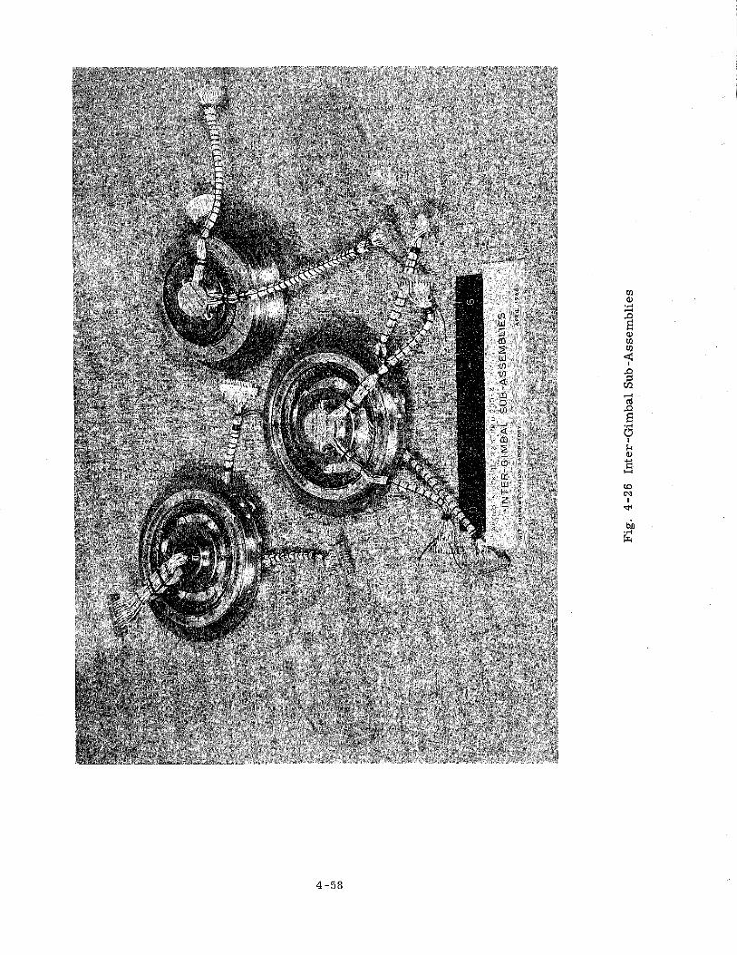
One inter-gimbal assembly contained a pancake-type dc servo-torque motor
having a 3 . 8 inch diameter a i r gap ( 3.. 1 2 f t . -1bs. / amp) , a 40 circuit slip ring as -
sembly, and a duplex pair of ball bearings preloaded to provide a predetermined
axia.1 yield rate of 7 micro-inches per pound. The inter-gimbal assembly housing
and stub shaft were made of beryllium. The stub shaft supported the torque motor
rotor and slip ring assembly, The slip rings were terminated in connectors which
interfaced with the stable member harness and the middle axis slip rings. The
slip ring wires were clamped to the housing a few inches away from the slip ring
assembly s o that they flexed with slight oscillations of the gimbal without the slip
rings and brushes moving in relation to one other. This eliminated slip ring wear
under most operating conditions. The bearings were floated axially to allow for
manufacturing tolerances and thermal expansion.
The other inter -gimbal assembly contained a combination 1 speed -16 speed
resolver transmitter, a 1 speed gyro e r r o r signal resolver, a 40 circuit slip ring
assembly, and a duplex pair of ball bearings preloaded the same a s those on the
other end of the axis. The stub shaft supported the resolver rotors and slip ring
assembly. The resolvers were accurately aligned, by the resolver manufacturer,
with respect to alignment slots on the stub shaft and housing. These slots engaged
pins on the stable member and middle gimbal. The bearings of this assembly were
fixed and therefore provided axial support for the stable member. The axis of ro-
tation, a s determined by the bearings, defined the inner axis, which had unlimited
rotation.
4.4.1.3 Components on the Middle Gimbal. There were no electrical components on
the middle gimbal. The middle gimbal was made up of two hydroformed 0. 040 inch
thick aluminum hemispheres pinned and bolted together at brazed aluminum flanges.
There were four additional flanges to which were attached the inner and middle axis
inter-gimbal assemblies. Pins on these flanges picked up the alignment slots of
the resolver inter -gimbal assemblies,
4.4.1.4 Components on the Middle Axis. The middle gimbal was supported in the
outer gimbal by a pair of pre-assembled inter-gimbal assemblies, one on each end
of the middle axis. They were s imilar to the inner axis inter-gimbal assemblies.
One assembly contained a pancake type dc servo torque motor having a 3.8 diameter
a i r gap, a 40 circuit slip ring assembly, and a preloaded duplex pair of bearings.
The bearings were floated axially. The other inter-gimbal assembly contained a
combination 1 speed and 1 6 speed resolver, a 40 circuit slip ring assembly, and a
fixed (not floating) duplex pair of preloaded ball bearings. The axis of rotation a s
determined by the bearings defined the middle gimbal axis. The middle gimbal had
unlimited rotational freedom about this axis.
4,4.1,5 Components on the Outer Gimbal. The outer gimbal was made up of two - -- hydroformed 0. 040 inchthick aluminum hemispheres pinned and bolted together at
brazed aluminum flanges. There were four additional flanges to which were attached
the middle and outer inter-gimbal assemblies. Pins on these flanges picked up the
alignment slots of the resolver inter-gimbal assemblies. The outer gimbal had
slots in it to permit forced convection of heated a i r between the middle gimbal and
the case. This was provided by two axial-flow blowers mounted on the outer gimbal.
The slots also permitted assembly of the outer gimbal since the flanges were internal.
4.4.1.6 Components on the Outer Axis. The outer gimbal was supported in the IMU
case by a pair of outer axis inter-gimbal assemblies, one at each end. They were
also similar to the inner axis inter- gimbal assemblies. One assembly contained
a pancake-type dc servo-torque motor having a 3 . 1 2 5 inch diameter a i r gap, a 50
circuit slip ring assembly, and a preloaded axially floating duplex pair of ball bear-
ings. The other inter-gimbal assembly contained a combination 1 speed and 16
speed resolver, a 50 circuit slip ring assembly and a fixed duplex pair of preloaded
ball bearings. The axis of rotation determined by the bearings defined the outer
axis. The outer gimbal had unlimited rotational freedom about this axis.
4.4.1.7 Components on the IMU Case. The IMU case was made from0.060 inch
thick aluminum hydroformed spherical sections with integral roll- bonded, inflated,
coolant passages. Two Seaton-Wilson hydraulic quickdisconnect fittings were a t -
tached for connection to the spacecraft water-glycol coolant system.
Mounting pads fo r mounting the IMU to the navigation base were accurately
machined to locate and align the IMU in two axes. The third axis was defined by
dowel bushings which engaged accurate holes on slots in the IMU case and navigation base.
Two 6 1 pin electrical connectors interfaced with the G & N harness; they were
keyed to prevent incorrect mating. An electrical sixteen speed resolver adjustment
module and a blower control relay were located inside one of the end covers that
sealed each end of the outer axis.
The case covers were sealed by the use of o- rings to effect a hermetic
seal of the IMU. This insured that the thermal transport medium ( a i r ) within the
IMU would not leak out during vacuum operation. Another benefit of hermetic seal-
ing was that a greater choice of engineering materials would be available inasmuch
a s the constraint on the use of toxic o r odorous materials and lubricants, and the
seizing of bearings in vacuum would be minimized.
4,4.1,8 Size and Weight. The IMU c a s e diameter was 12,5 inches; i d was 14 inches
a c r o s s the end covers on the outer axis. The voluirie of the %MU was approximately
1100 cubic inches, and it weighed about 42. 5 pounds.
4.4. 2 Thermal Design
4.4.2.1 General. The IMU temperature control systems were designed to maintain
the gyroscope and accelerometer operating temperature within narrow limits.
Thermally, the IMU could have been viewed as three concentric aluminum spheres,
the inner sphere a s the middle gimbal, the next sphere as the outer gimbal and the
external one a s the case.
A liquid-to-air heat exchanger covered pai-t of the surface a rea of the case.
Between the middle gimbal and case was an a i r circuit that used two blowers
mounted on the outer gimbal to force a i r from the area of the middle gimbal towards
the case heat exchanger. The IMU heat transfer is shown in Figure 4-27.
The Block I and Block I1 IMU1s were thermally similar. The respective
temperature control schemes were also very similar. In both instances tempera-
tu re deviations from a fixed absolute temperature werc detected. These temper-
a ture deviations were used to control heater power to the stable member. The
implementation of the control schemes was, however, different.
4.4.2.2 Block I Thermal Design. The Block I IMU temperature control design was
hampered from the s ta r t by an inadequate definition of the environment within which
the IMU was expected to perform. In particular, the spacecraft thermal environ-
ment, primary coolant loop characteristics, and prime power voltage excursions
were unknown. F o r these reasons, an attempt was made to include much flexibility
into the design in order to be able to adjust to the actual environments as they be-
came better defined.
The use of thermal heat of fusion materials to serve a s a heat reservoir was
considered early in the design. This approach was taken to conserve electrical
power. A thermal study, one of the f i rs t to define system operation fo r a lunar
landing mission, showed that though this concept was sound, the use of these ma-
ter ia ls was unworkable based on IMU time line usage. This approach was abandoned
and an electronic temperature control system was designed.
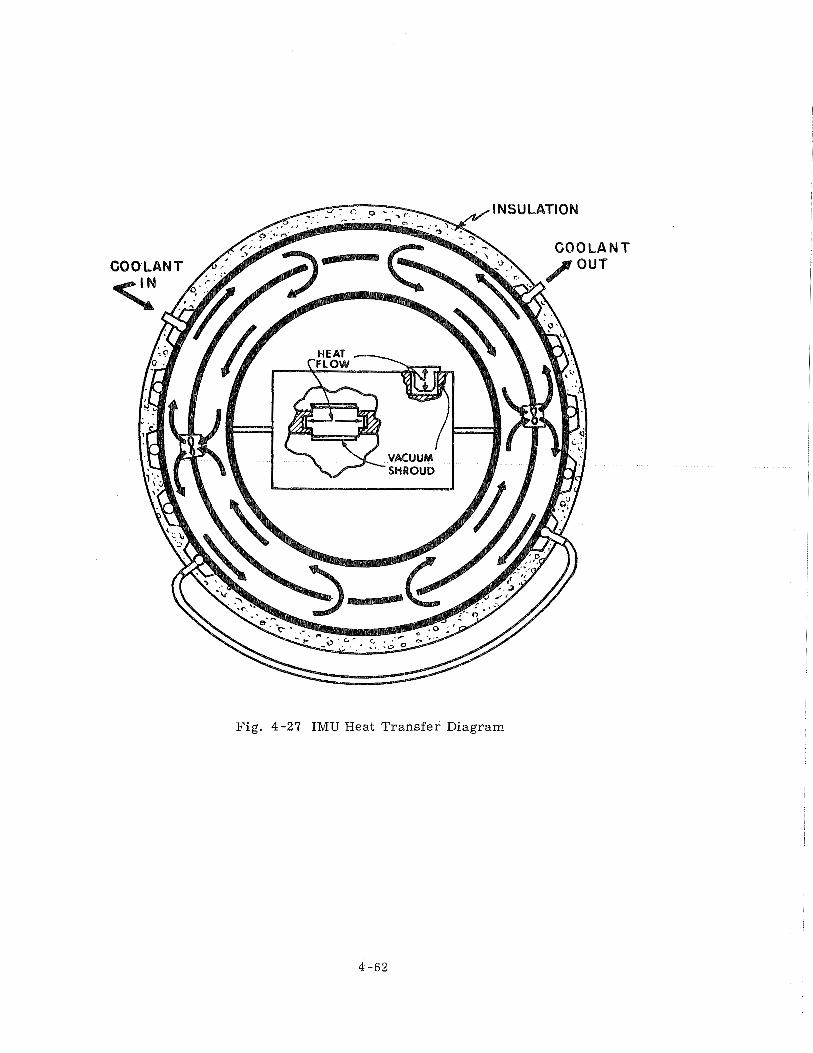
Fig. 4-27 IMU Heat Transfer Diagram
The temperature control scheme utilized resi.stance wire temperature
sensing elements located in the I316 end mountss. These sensing elements connected
in ser ies , measured the average temperature of the three gyroscopes. They
formed one a r m of a four a rm resistance bridge. The rernainder of the bridge was
located in the PSA. The bridge e r r o r signal, proportional to the temperature d i f -
ference between the actual average gyroscope temperature and the desired tempera-
ture, controlled the operation of magnetic amplifiers in the power servo assembly
( PSA). These, in turn, provided power proportional to temperature deviation.
The power was in the form of a 20V, 3200 pps pulse-width modulated square-wave
voltage to the stable member heaters.
An additional se t of heaters, controlled by a thermostat on the stable
member and powered directly from spacecraft prime power to the G& N system,
comprised a redundant temperature control system. This did not provide the pre-
cise control of the primary system but was adequate to satisfy the crew safety and
mission success requirements.
Temperature sensing thermistors within the gyroscopes were used to moni-
t o r the gyroscope temperature. They were connected in ser ies and formed one
a r m of a four a r m resistance bridge. The other elements of the bridge were
located in the PSA. The e r r o r signal output of this bridge controlled another mag-
netic amplifier which turned on an alarm light if the gyro temperature exceeded
specified limits. It also provided an output for telemetry of IRIG temperature and
an output to the front of the PSA tray for use by the in-flight failure monitor.
The temperature sensing resistance elements of the accelerometers were
used to monitor PIP temperature in a manner similar to the gyroscope monitoring
scheme.
The two blowers on the middle gimbal were used to vary the thermal r e -
sistance between the inner gimbal and the case. Saturable reactors on the outer
gimbal varied the blower speed a s a function of stable member heater power.
4.4.2.3 Block 11 Thermal Design. The Block I1 IMU temperature control design
effort was undertaken to develop a smaller, lighter, simpler, more reliable temp-
erature control system for the Block I1 IMU. Advantage was taken of the knowledge
and experience gained from the Block I INIU. The Block I1 spacecraft was essen-
tially identical to the Block P vehicle; therefore, the IMU environment was well
known. A good thermal model of the IMU was developed fromBlock I experience.
The uncontrolled IMU heat sources, e. g, , inertial components, torquers, r e -
solvers, and gimbal mounted electronics, were well defined.
Temperature control. of t he Block Il was a.ccomplished by u s k g a mercury
thermostat a s the temperature sensing element in bistable temperature control
system. Additional mercury thermostats were used to provide an out-of - l imits
temperature a l a r m indication and fo r control of the two blowers. A sensor
of this type was used in the Block I IMU for emergency control. It proved t o be
accurate, stable, extremely reliable and had a very smal l dead band. F igure 4-28
is an e lect r ica l schematic diagram of the Block I1 temperature control system.
As with Block I, heaters were located on each end of the gyroscopes and on
one end of each accelerometer. Two additional cartr idge heaters were embedded
within the stable member . Each of the four thermosta t modules contained one
control, o r anticipatory heater, and one bias heater. Padding res i s to r s were placed
in s e r i e s with the heaters to adjust the power in each heater. The temperature
difference between the IRIGs and the P I P s was adjusted by properly proportioning
the amount of power in each heater.
The temperature control power required to keep the control thermostat
within its l imi t cycle operating range varied in response to environmental and
power changes within the IMU. The effect of control power variations on iner t ia l
component temperature was minimized by adjusting appropriate PIP control heater
and control thermostat anticipatory heater padding res is tors . Fixed bias heat was
applied to the PIPs t o bring them to proper operating temperature whenever the
ISS was in the operate mode. The stable member temperature was affected by
fluctuations in gyro wheel power. As wheel power increased, f o r example, because
of an increase in wheel voltage, the control power and therefore the stable member
temperature decreased. To keep the P I P temperature f rom decreasing along with
the stable member , it was necessary to add m o r e heat to the PIPs. This was a c -
complished by energizing the PIP fixed bias heaters with gyro wheel supply voltage.
The performance characterist ics of the temperature control sys tem a r e
shown in Fig. 4-29. The thermostat cycle of operation at 5070 duty cycle was 0.3
while a t the s a m e t ime the gyroscope limit cycle was attenuated to 0.00065 degree
F and that of the accelerometers to 0.009 degree F. The stable member temp-
e ra tu re continued t o drop a s the control power was increased, a s one might expect,
but the inert ial component temperature remained constant throughout the power
range. The blower extended the dynamic range of operation, was infrequently used
and was limit-cycled by a thermostat. There were two separate sensors to detect
temperature extremes and ale13 the astronauts. In addition, high l imit mechanica.1
thermostats were used in every heater power line to prevent an over heated condi-
tion. These were s e t to open the heater power a t a temperature of about loop over
the normal control temperature . These were ra re ly used but when necessary p r e -
vented damage to valuable equipment,
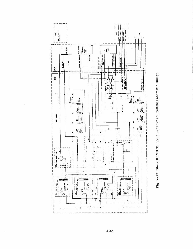
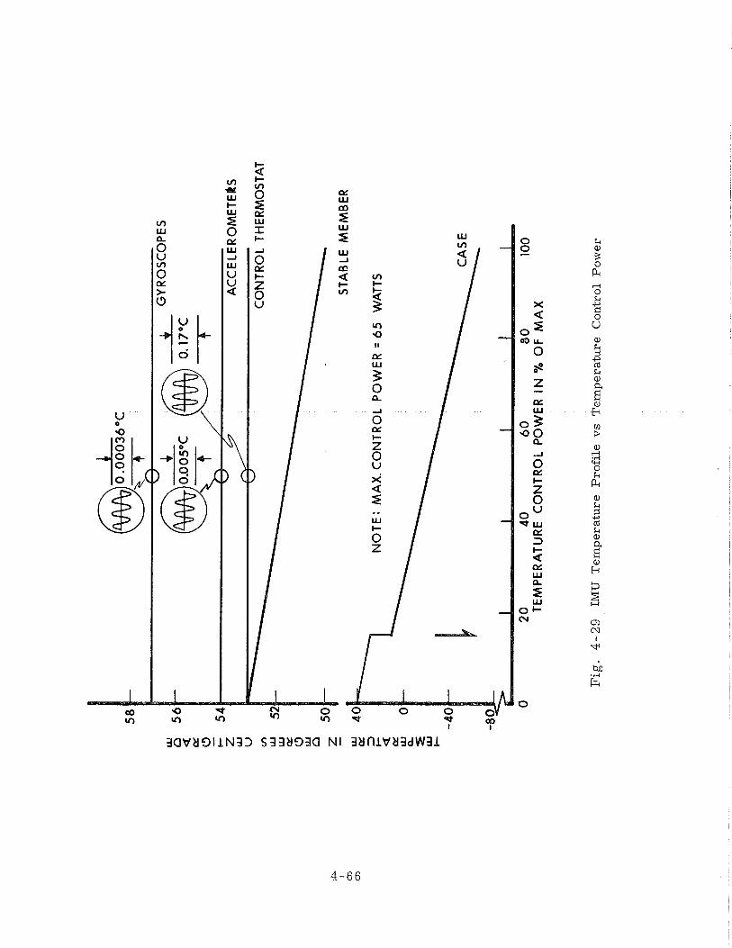
58
56
a
1Y 0
54
z U
J U
m
THE
RM
OS
TAT
LU
52
LU
1Y
(3
UI 0
50
z -
STA
BLE
ME
MB
ER
4
0
3 2
NO
TE
: M
AX
. CO
NT
RO
L P
OW
ER
= 6
5
WA
TTS
1Y
UJ
0
2 LU
E-
-40
20
4
0
60
8
0
TEM
PE
RA
TUR
E C
ON
TR
OL
PO
WE
R I
N %
OF
MA
X
Fig
. 4
-29
IM
U
Tem
pera
ture
Pro
file
vs
Tem
pera
ture
C
on
tro
l P
ow
er
4. 4. 3 Mechanical Tests
4.4.3.1 Acceleration, The Block I and Block II mechanical integrity IMUs were
accelerated at 10, 20, and 30 g ' s along their outer axis. These tests were run to
determine the torque motor capabilities.
Torque ( % of max. )
1 g
10 g ' s
20 g 's
30 g ' s
The gimbal breakaway torques were measured before and after these tests with no
significant change measured.
( 1 ) General - - Two mechanical evaluation IMUs were built for both Block I
and Block 11: a Vibration Model (IMU-VM and IMU 200-VM) and a Mechanical
Integrity Model ( IMU-2 and IMU -200-2 ). The vibration models contained a dummy
mass to simulate the stabilized member, and contained aluminum stub shafts and
bearing mounts sized to simulate the stiffness of the final IMU design. Tolerances
were loose and no torque motors o r resolvers were installed. This model was
used to determine resonant frequencies and transmissibilities.
The mechanical integrity IMUs were identical to functional IMUs with
dummy inertial components that contained the vibration and acceleration pickups.
These IMUs were used for vibration, acceleration, and shock tests to evaluate
the adequacy of the mechanical design.
( 2 ) Vibration Tests - - The IMU models were vibrated at 1, 2, & 3 g ' s ( rms)
sinusoidal input with a logarithmic frequency sweep from 20-2000-20 Hz. in 16
minutes along each axis. Each IMU was also vibrated with a 5 g ( rms ) random
noise input, per the NAA specification, along each axis. The results of these tests
indicated resonant frequencies varying from 110 to 170 Hz. with transmissibilities
of 7 to 22. A problem developed during the initial vibration tests of the Block I IMU
and dampers were added. This is discussed in Section 4.4.4.2. The Block 11 IMU
vibration t e s t s verified that the design w a s a d ~ q n a t e , A Block I1 %MU was vibrated
on the GM and L M navigation bases. The vibration input to the navigation base was
in accordance with ei ther the NAA o r the GAEC random vibration specification. In
each case , the input to the IMU was much l e s s s e v e r e than the sinusoidal inputs
used during the design evaluation tes ts .
( 3 ) Shock T e s t s - - The Block II IMU was subjected to 20 g peak, sawtooth,
6 ms r i s e , and 1 m s decay t ime shocks twice along each axis with no problems de -
veloping.
4.4.3.3 Leak Tests . Al l IMU c a s e par ts were helium leak-checked p r io r to assembly.
IMUs were p ressur ized to 24.7 psia fo r varying lengths of t ime and during the
shock and vibration t e s t s with no measurable change in pressure .
4 .4 .4 Design Prob lems
4.4.4.1 Changes in Materials . A brief review of the mater ia ls incorporated in the
Block I and Block I1 Apollo IMUs showed that the re were two that were new and
different to th is type of system. These were: ( 1 ) the fr ict ion mater ia l that was
used in the vibration dampers of the Block I - 1 C O sys tems, and ( 2 ) the Roll-Bond
mate r i a l used f o r both the Block I and Block I1 water -glycol c a s e heat exchangers.
Vibration dampers were added t o the Block I IMUs when a high vibration
transmissibil i ty was discovered during ear ly tes ts . The selection of the type of
damper and mate r i a l was greatly influenced by the limited space available in the
IMU. Some important character is t ics that the damper mater ia l had to possess
were ( 1 ) l a rge dynamic coefficient of friction, ( 2 ) good wear res is tance , ( 3 ) be
very rigid, ( 4 ) stable under high temperatures , and ( 5 ) be machineable.
Johns Manville fr ict ion mater ia l s tyle #230 was determined to be the optimum
available mate r i a l f o r this application. Final inspection of IMU -2, af ter vibration
t e s t s , revealed that the dampers and f r ic t ion mate r i a l had not degraded sys tem
performance.
An initial requirement f o r the Apollo IMU was that the fluid heat exchanger
should be a n integral pa r t of the IMU. This led to the idea of using a ro l l - bond
m a t e r i a l ( s i m i l a r to that used in r e f r ige ra to r s ) which had many advantages such
a s light weight, low the rmal resistance, and required minimum volume in the CM
and LM.
Techniques f o r roll-bonding of f l a tpane l s were well establi.shed. However.,
it was necessary to develop techniques to hydroform these panels into hemispheres,
inflate the passages af ter hydroforming, and then machine and braze the pa r t s to
f o r m the spher ical €MU case . The mater ia l f o r the rol l - bond par t s was bf6061
aluminum clad with #lP00 aluminum to insure a good bond. During fabrication of
the IMU case, a hydrostatic proof t e s t was performed a t 90 psig to insure that the
p a r t s were structurally sound.
4.4.4.2 Vibration Problems. As a result of high vibration magnification seen a t
the resonant frequency on the Block I IMU,. fatigue c racks developed in the middle
and outer axis stub shafts. Consequently, the stub shafts had to be redesigned and
vibration dampers added t o each axis in the torque motor inter-gimbal assemblies .
St ra in gage t e s t s then indicated a reduction in the stub shaft s t r e s s e s by a factor
of 3. This, with the reduction of the transmissibil i ty by the addition of dampers ,
resulted in a reduction of the s t r e s s e s in the stub shafts t o a level well below the
fatigue l imit of the mater ia l .
Various types of dampers were tested and a friction damper, which was the
best for the space available, was added at the floated bearings.
4.4.4.3 Thermal Problems. The Block I temperature control system proved to be
ve ry reliable and presented very few problems af ter the design was completed.
Considerable effort was expended in developing the magnetic amplifiers. Because
weight was a major consideration in the overall G & N design, the early magnetic
amplifiers were designed to be a s compact a s possible. This led t o the use of very
s m a l l wire s i zes and resulted in fai lures f rom wire breakage. The amplifiers
were redesigned in somewhat l a r g e r packages with heavier wire; consequently, no
fur ther fa i lures occurred.
Another sys tem problem was discovered during early sys tem tes ts . The
3200 pps pulse-width modulated temperature control power was observed to generate
6400 pps spikes which could be seen throughout the sys tem. An IMU wiring harness
change reduced these spikes to tolerable levels.
The Block I1 sys tem initially had severa l mercury thermostat fai lures. All
of these fa i lures indicated handling in excess of the specified 100 g 's . A design
change was made to incorporate a mercury thermostat with a 500 g, 2 millisecond
duration specification, thus solving a l l breakage problems.
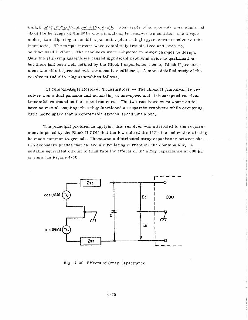
4.4-4-4 1nCergin1ha.l Component Problems. F o u r types of components were clustered - - about the bearings of the IMU: one gimbal-angle resolver transmi"cer, one torque
motor, two s l ip-r ing assembl ies p e r axis, plus a single g y r o - e r r o r r e so lve r on the
inner axis. 'The torque motors were completely t rouble-f ree and need not
be discussed fur ther . The resolvers were subjected to minor changes in design.
Only the s l ip-r ing assembl ies caused significant problems p r io r to qualification,
but these had been well defined by the Block I experience; hence, Block I1 procure-
ment was able to proceed with reasonable confidence. A m o r e detailed study of the
reso lve r s and sl ip-ring assembl ies follows.
( 1) Gimbal-Angle Resolver Transmi t t e r s - - The Block 11 gimbal-angle r e -
so lve r was a dual pancake unit consisting of one-speed and sixteen-speed resolver
t r ansmi t t e r s wound on the s a m e iron core . The two resolvers were wound a s to
have no mutual coupling; thus they functioned a s separa te resolvers while occupying
l i t t le m o r e space than a comparable sixteen-speed unit alone.
The principal problem in applying this resolver was attributed to the require-
ment imposed by the Block I1 CDU that the low s ide of the 16X s ine and cosine winding
be made common to ground. T h e r e was a distributed s t r a y capacitance between the
two secondary phases that caused a circulating current via the common low. A
suitable equivalent circuit to i l lus t ra te the effects of the s t r a y capacitance a t 800 Hz
is shown in F igure 4-30.
Fig. 4-30 Effects of Stray Capacitance
Z S S is the short -circuit output impedance of the resolver, and C is one-half
the M a 1 capacitance between the secondary phases. Both an e r ro r in indicated
angle and an additional quadra.ture voltage were impressed on the CDU input voltages
by current flowing through capacitance C and the equivalent output impedances.
Within a close approximation, both the e r r o r and the quadrature had the form cos
(32A). Whereas e r r o r s of this form a r e usually corrected in high accuracy resolvers,
there was no simple method to suppress this quadrature. As a result, a decision
to wind the 16X secondaries for a step-down voltage ratio was made. The output
impedance was greatly reduced and the s t ray capacitance reduced a s well.
The other problematical feature of the Block I1 gimbal-angle resolver was
increased e r ro r s a s compared with the Block I design. This was essentially caused
by the rather poor shape of the iron core required to minimize the IMU size.
Another factor was less accurate ( although within tolerance) grinding of the beryl-
lium parts that mount the resolver as compared to the Block I parts (which had
been subcontracted to a beryllium specialty house). In order to get reasonable
yield, the vendor altered the winding pattern to further cancel some slot harmonics
in the e r rors , and the specified maximum e r r o r was raised from 20 to 25 a r c seconds.
( 2 ) Gyro-Error Resolver - - The gyro e r r o r resolver was mounted on the
inner axis, adjacent to the gimbal angle resolver. The e r r o r signals of the X and
Z gyroscopes were rotated by this resolver into middle-gimbal coordinates, mak-
ing the operation of the gimbal servos independent of the inner gimbal angle.
The principal constraints on the design of this resolver were:
a. It had to function with small signals when the gyros were near null and
yet not saturate before the gyro preamplifiers did. This requirement necessitated
an iron core with excellent linearity.
b. It had to be shielded from the adjacent gimbal-angle resolver.
c. Its axial width including the shields had to be small to conserve space
and weight.
d. Its impedance levelhad to be a reasonable compromise between loading
effects on the gyro preamplifiers, and i ts contribution to source impedance for the
wiring capacitance and demodulator loading. In this regard, one must note that
the demodulator load was a function of applied voltage. Also observe that both
signal phase shift a s well as magnitude had to be maintained across the resolver.
e , An 0,003 inch minimum a i r gap was specified f o r the resolver to insure
against mechanical interference resulting from tolerance accumulation and s t ress
effects.
f , The shields influenced the performance of both the gyro e r ro r and the
gimbal angle resolver.
The difficult design problem of the inner-axis resolvers was attenuating the
3200 Hz cross-coupling between them. Only one vendor achieved the specifications
and qualified a s a source. Because the shield design would be much easier with
more axial space, this problem interacted strongly with other parameters which
could have been improved with more space. In the meantime, those responsible
fo r stabilization loop design were evaluating the gyro e r r o r resolver design based
on a "figure of merit" consisting of the ratio of tuned open circuit input impedance
to the magnitude of the short-circuit output impedance. Such a figure, being based
on effects in the stabilization loop circuits only, did not weigh the more complex
aspects of space and cross -coupling.
Although prototype gyro e r ro r resolvers successfully met a l l the specifica-
tions, a difficulty developed in production. Impedances and the "figure of merit"
were highly sensitive to both a i r gap length and lamination magnetic properties. In
early 1966, a position was reached where almost no yield was obtained that met the
minimum a i r gap and also the required impedance. To keep on schedule, a few units
were accepted to a revision of the specification calling for a minimum a i r gap of
2 . 2 rather than 3.0 mils. This was made possible without reducing the minimum
running clearance by performing the final grinds with the laminations already mounted
in the stub shaft and bearing mount. Meanwhile, a new winding was designed which,
with a 3-mil a i r gap, achieved rather different but quite acceptable impedances.
( 3 ) Slip-Ring Assemblies - - The Block I1 slip -ring assemblies never actually
caused significant problems. This was true, however, only because a number of
steps taken to achieve qualification of the Block I assemblies paved the way for
Block 11. The ensuing discussion will therefore be a short review of Block Iprob-
lems, solutions, and resulting effects on Block 11.
The early Apollo experience with slip rings was based on assemblies from
Electro-Tec, Poly Scientific, and Collectron Corporations, Between experience in
prototype IMUs and attempts to qualify all three sources, an impressive list of
failures was accumulated. Contamination, bearing failures, high noise, i. e., r e -
sistance variation with rotation, and various minor mechanical problems were
experienced, Poly Scientific Corporation was elimina.ted when they were unable to
cure a contamhation problem after many a.t"crnpts, Gollectron had trouble main-
taining bearing preload but was eliminated mainly because of high wear and noise
early in ah1 life tes ts , This left Electro Tec, who had experienced numerous small
bearing failures caused by contamination after exposure to a severe humidity cycle.
Electro Tec also had some out-of-tolerance noise at the conclusion of the life
test.
The prospects of the Electro Tec units actually were found to be good. They
had experienced difficulty only with the smaller bearing. Their Block 11 design
used two of the larger size, however. Furthermore, on teardown, most bearing
failures were found to be the result of improper lubrication. Consequently, Electro
Tec began buying the bearing pre-lubricated with good results. Next, a humidity
cycle was specified which more realistically represented the actual conditions of
storage and use, and the contamination failures ceased. Finally it was recognized
that the life test, o r , officially, Extended Performance Test, was conducted with
oscillations and slews which gave rotational rates up to three times those in an
IMU under a locked -gimbal tumble. After changing to a more realistic activity
level during the test , Electro Tec slip ring assemblies completed life testing within
the specified noise limits. (The 10 cpm -1- 360°/ -360' oscillation was changed to
2 cps, 3' - +lo double amplitudedither, superimposed over a 112 to 2 rpm rotation. )
These noise limits, more nearly,although still severe, simulated the con-
ditions expected in testing and operation of the IMU. The actual slip ring motions
in an IMU were impossible to duplicate exactly since they depended on test o r flight
conditions. F o r a large percent of the time during tests o r flight the brushes were
not moving over the rings since the IMU was stabilized o r was moving at meru
rates as a result of gyro drift. Periodically, the brushes were rotated to a new
position when the IMU was rotated to a new position by the test fixture o r the space-
craft. As the axes arrived at a new orientation, there were some minute (seconds of
a r c ) random oscillations a s the IMU nulled itself at the new location. The normal
wear of the slip ring in the IMU was caused by random oscillations. The slow rpm
was superimposed so that all areas of the ring were checked since the location of
the brushes on the ring varied from slip ring to slip ring in the IMU. A relatively
high rpm test was included every 100 hours to simulate the condition during tests
where a malfunction in the system would cause a gimbal axis to rotate with full
torque from the torque motors. The 600 rpm requirement in the original tes t was
in e r r o r and was changed to 200 rpm since the EMU was limited to less than this
rate because of friction and motor back emf.
The resu.lts were that Elect ro Tee Corporation was the only qualified sup-
pl ier of Block 1 sl ip ring assemblies and became the principal supplier f o r Block 11
while other manufacturers attempted to c u r e thei r djff iculties and qualify fo r
Block IS,
Coupling Display Unit ( CDU )
4.5. 1 Block I CDU
The Block I coupling display units provided a coupling between the Apollo
Guidance Computer (AGC) o r the astronaut and the IMU and the optics. Either
the AGC o r the astronaut could have transmitted angular data to the IMU. The CDU
also provided the astronaut with a visual readout of the IMU and optics angular data
during the coarse align, f ine align, and manual CDU modes of operation. Desired
angles were transmitted by the CDU loop to the IMX in analog f o r m during the coarse
align and manual CDU modes. The CDU loop was also capable of repeating the IMU
gimbal angles and the optics angles, and transmitting this angular data t o the AGC
in digital f o r m in the fine align mode. The CDUs in the ISS could also have been
used to provide a coupling between the astronaut o r AGC and the spacecraft autopilot.
Five CDUs were required by the G & N system, th ree in the ISS, and two in the
optical subsystem (OSS ). Each CDU contained a servo motor-tachometer, four
resolvers , a digital encoder, th ree display dials, and a thumbwheel; a l l were inter-
connected by a s ta inless s t ee l g e a r train. Each CDU also contained a slew switch,
which was not utilized in the OSS CDU loop application. The gear t r a in was driven
by e i ther the thumbwheel o r the servo motor-tachometer. The se rvo motor-
tachometer was an 800 cps unit that drove the CDU gear t r a in and produced a feed-
back signal proportional to the output shaft rate. The motor was driven by the
Motor Drive Amplifier (MDA) in the PSA. Input signals to the MDA were received
f r o m the CDU resolvers , the digital-to-analog converter in the PSA, and the slew
switch, al l of which represented CDU loop e r r o r s . The motor converted the various
CDU loop e r r o r signals into the appropriate output shaft angle and velocity. The
tachometer provided a negative feedback signal proportional t o the motor shaft
speed to the MDA. The slew switch provided a 6.25 Volt, 800 Hz signal of ze ro
o r pi phase to the MDA to position the ISS CDUs during the manual CDU mode of
operation. The four reso lvers were utilized either for angular data transmission
o r angular e r r o r resolution. The specific resolvers utilized and the i r functions
depend on the CDU application. The digital encoder (F igure 4-31 ) converted the
angular motion of the CDU output shaft into a digital signal which could be used by
the AGC.
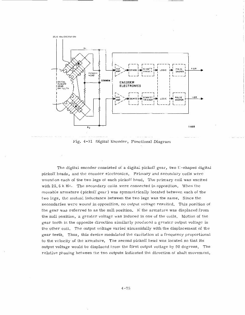
25.6 KHz EXCITATION
Fig. 4 -3 1 Digital Encoder, Functional Diagram
The digital encoder consisted of a digital pickoff gear, two U-shaped digital
pickoff heads, and the encoder electronics. P r i m a r y and secondary coils were
wound-on each of the two legs of each pickoff head. The p r imary coil was excited
with 25.6 k Hz. The secondary coils were connected in opposition. When the
movable a r m a t u r e (pickoff g e a r ) was symmetrically located between each of the
two legs , the mutual inductance between the two legs was the same. Since the
secondaries were wound in opposition, no output voltage resulted. This position of
the gea r was re fe r red to a s the null position. If the a rmature was displaced f r o m
the null position, a g rea te r voltage was induced in one of the coils. Motion of the
gea r tooth in the opposite direction s imi lar ly produced a g rea te r output voltage in
the other coil. The output voltage varied sinusoidally with the displacement of the
g e a r teeth. Thus, this device modulated the excitation at a frequency proportional
t o the velocity of the armature. The second pickoff head was located s o that its
output voltage would be displaced f rom the first output voltage by 90 degrees. The
relat ive phasing between the two outputs indicated the direction of shaft movement.
The f i r s t pogtion of the digital encoder electronics was a preamplif ier which
was followed by a synchronous demodulator. The output of the demodulator was
converted into square waves by the Schmitt t r igger. The square wave outputs were
then fed into a logic network which identified the direction of rotation and produced
voltage spikes on one output line ( + ~ 4 ) f o r clockwise rotation of shaft and on the
other l ine ( - A $ ) fo r counterclockwise rotation. These spikes were then converted
to the proper logic level f o r the AGC by pulse shaping networks. Each pulse
presented to the AGC represented 40 arc-seconds of shaft t r ave l when used with the
ISS, o r 20 arc-seconds when used with the optics. The logic of the encoder elec-
t ronics provided two distinct encoder modes of operation, ei ther one pulse p e r gea r
tooth o r two pulses p e r g e a r tooth. Again, the modes of operation depended on
subsystem mechanization.
While the digital encoder was providing the AGC with information about the
position of the CDU, the AGC had also to be provided with a means of controlling
the movement of the CDU. This was accomplished by the digital-to-analog converter
(DAC). The DAC received commands f r o m the AGC and converted these commands
t o an electr ical output usable in the MDA. The inputs f r o m the AGC were pulses of
The feedback signal f r o m the encoder a lso consisted of pulses, but the repetition
r a t e varied according t o the speed of encoder pickoff gea r rotation. The AGC inputs
caused a capacitor in the DAC to be charged. The charge on this capacitor was
reflected into the DAC output s tage by two integrated choppers operating at 800 Hz
The output of the DAC was an 800 Hz square wave with a maximum amplitude of
approximately 10 Volts peak-to -peak. This output was utilized by the motor drive
ampl i f ier to position the CDU. The negative feedback f rom the encoder was required
to insure that only a defined amount of CDU movement p e r pulse would occur f rom
the AGC. The encoder input discharged the capacitor that had previously been
charged by the AGC input, therebyshutting off the DAC.
4. 5. 2 Block I1
The Block I1 coupling data unit comprised the centra l angle junction box
between the IMU, optics, computer and the certain portions of the spacecraft analog
e lec t r ica l interfaces. T h e r e were three basic portions of the CDU: the angle read
sys tem o r analog -to -digital conversion process, the digital-to -analog conversion
process , and a portion of the moding controls f o r the guidance system. The
analog-to-digital sys tem is covered in some detail while the o ther portions a r e only
briefly described.
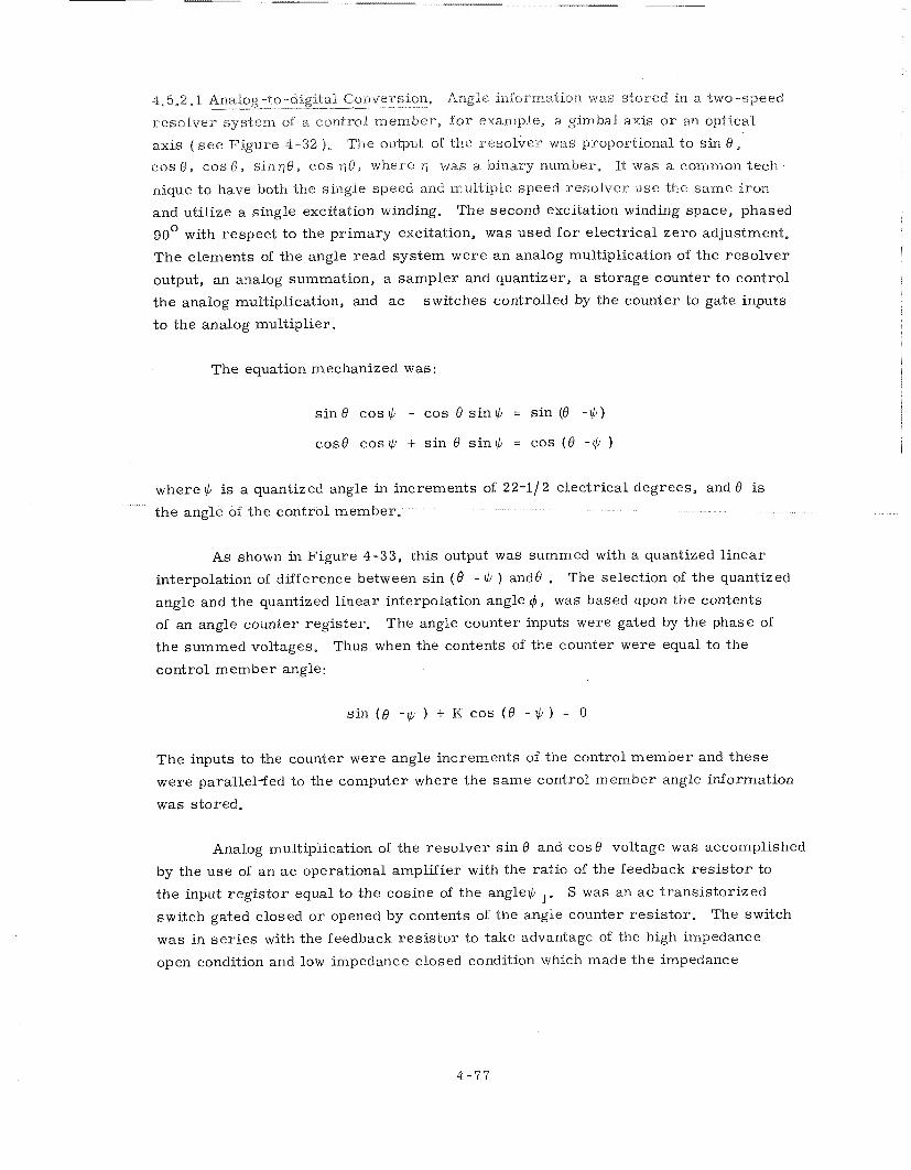
4.5,2,1 Aria-log-to-digital Conversion, Angle information was stored in a Lwo-speed -- -- -- --
resolver sys tem of a control member , f o r example, a gimbal axis o r an optical
axis ( s e e Figure 4-32 ). The output of the resolver was proportional to sin 8 ,
cos 8 , cos 8 , s inq0, cos q0, where q was a binary number, It was a common teeh-
nique to have both the single speed and multiple speed resolver use the sa-me i ron
and utilize a single excitation winding. The second excitation winding space, phased
go0 with respect t o the pr imary excitation, was used f o r electrical ze ro adjustment.
The elements of the angle read system were a n analog multiplication of the resolver
output, an analog summation, a sampler and quantizer, a storage counter t o control
the analog multiplication, and a c switches controlled by the counter to gate inputs
t o the analog multiplier.
The equation mechanized was :
s in 8 cos G - cos 0 s i n * = s in (0 - * )
cos9 c o s * + s i n 0 s i n * = cos (8 -* ) where $ is a quantized angle in increments of 22-11 2 electrical degrees, and 0 is
the angle of the control member.
As shown in Figure 4-33, this output was summed with a quantized l inear
interpolakion of difference between sin (6' - $ ) and8 . The selection of the quantized
angle and the quantized l inear interpolation ang led , was based upon the contents
of an angle counter register . The angle counter inputs were gated by the phase of
the summed voltages. Thus when the contents of the counter were equal to the
control member angle:
s in ( 8 - @ ) + K cos (8 - + ) = 0
The inputs to the counter were angle increments of the control member and these
were parallel-fed to the computer where the same control member angle information
was stored.
Analog multiplication of the resolver s in 8 and cos 8 voltage was accomplished
by the use of an a c operational amplifier with the ratio of the feedback res i s to r to
the input regis tor equal to the cosine of the angle* S was an a c transistorized
switch gated closed o r opened by contents of the angle counter res i s to r . The switch
was in s e r i e s with the feedback res i s to r to take advantage of the high impedance
open condition and low impedance closed condition which made the impedance
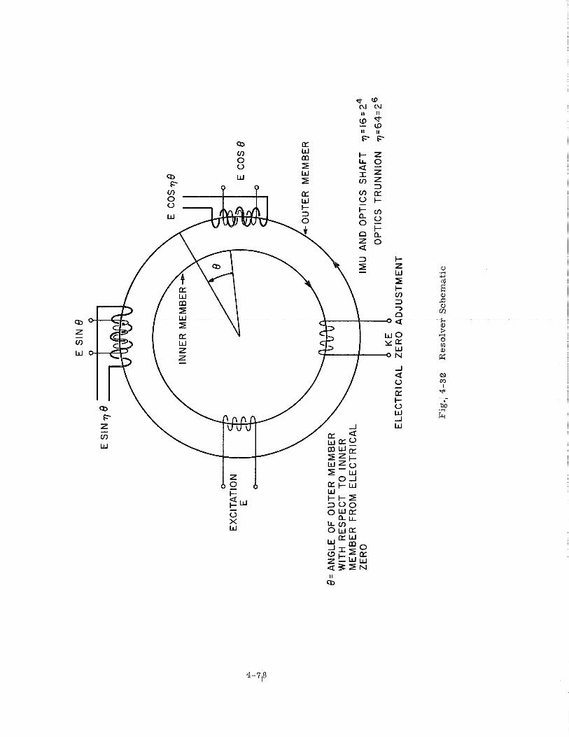
E S
IN 8
Q
Q
INN
ER
ME
MB
E
OU
TER
M
EM
BE
R
AN
GLE
O
F O
UT
ER
M
EM
BE
R
WIT
H
RE
SP
EC
T
TO
INN
ER
M
EM
BE
R F
RO
M E
LE
CT
RIC
AL
ZE
RO
IM
U A
ND
OP
TIC
S
SH
AF
T
71 O
PT
ICS
TR
UN
NIO
N
7
EL
EC
TR
ICA
L
ZE
RO
A
DJU
ST
ME
NT
Fig
.1 4
-3p
R
eso
lver
Sch
em
ati
c
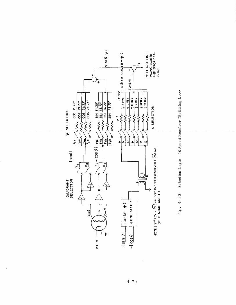
REF
QU
AD
RA
NT
$
S
EL
EC
TIO
N
SE
LE
CT
ION
I S
IN^'^
CO
S 1
1.25
.
1 Is' N(s
-yl
,+
FIN
E
* A
n
NO
TE
( 2-
" R
EV
= 1
0.5
min
FO
R 1
6 SP
EED
RES
OLV
ER =
39
6 s
ec
OF
GIM
BA
L A
NG
LE
)
- -.
K S
EL
EC
TIO
N
MIX
ING
LIM
ITE
R
AN
D E
RRO
R D
ET-
E
CT
OR
I'ig.
4
- 3
3
Sel
ecti
on
Lo
gic
- 1
6 S
pee
d R
eso
lver
Dig
itiz
ing
Lo
op
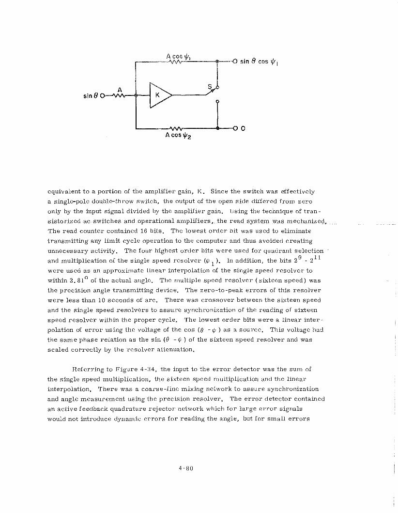
sin 8 CBS $,
I
equivalent t o a portion of the amplifier gain, K . Since the switch was effectively
a single-pole double-throw switch, the output of the open side differed f rom zero
only by the input signal divided by the amplifier gain. Using the technique of t r an-
sistorized a c switches and operational amplifiers, the read system was mechanized.
The read counter contained 16 bits. The lowest o r d e r bit was used to eliminate
transmitt ing any l imit cycle operation to the computer and thus avoided creating
unnecessary activity. The four highest o rder bits were used f o r quadrant selection
and multiplication of the single speed resolver ($ In addition, the bits 2' - 2 11
were used a s an approximate l inear interpolation of the single speed resolver to
within 2. 81° of the actual angle. The multiple speed resolver ( sixteen speed ) was
the precision angle transmitting device. The zero-to-peak e r r o r s of this resolver
were l e s s than 10 seconds of arc . There was crossover between the sixteen speed
and the single speed reso lvers to assure synchronization of the reading of sixteen
speed resolver within the proper cycle. The lowest order bits were a l inear in ter-
polation of e r r o r using the voltage of the cos ( 0 - d/ ) a s a source. This voltage had
the s a m e phase relation a s the s in (8 - Q ) of the sixteen speed resolver and was
scaled correctly by the resolver attenuation.
Referring to F igure 4-34, the input to the e r r o r detector was the sum of
the single speed multiplication, the sixteen speed multiplication and the l inear
interpolation. There was a coarse-fine mixing network to assure synchronization
and angle measurement using the precision resolver. The e r r o r detector contained
an active feedback quadrature re jector network which f o r large e r r o r signals
would not introduce dynamic e r r o r s f o r reading the angle, but f o r smal l e r r o r s
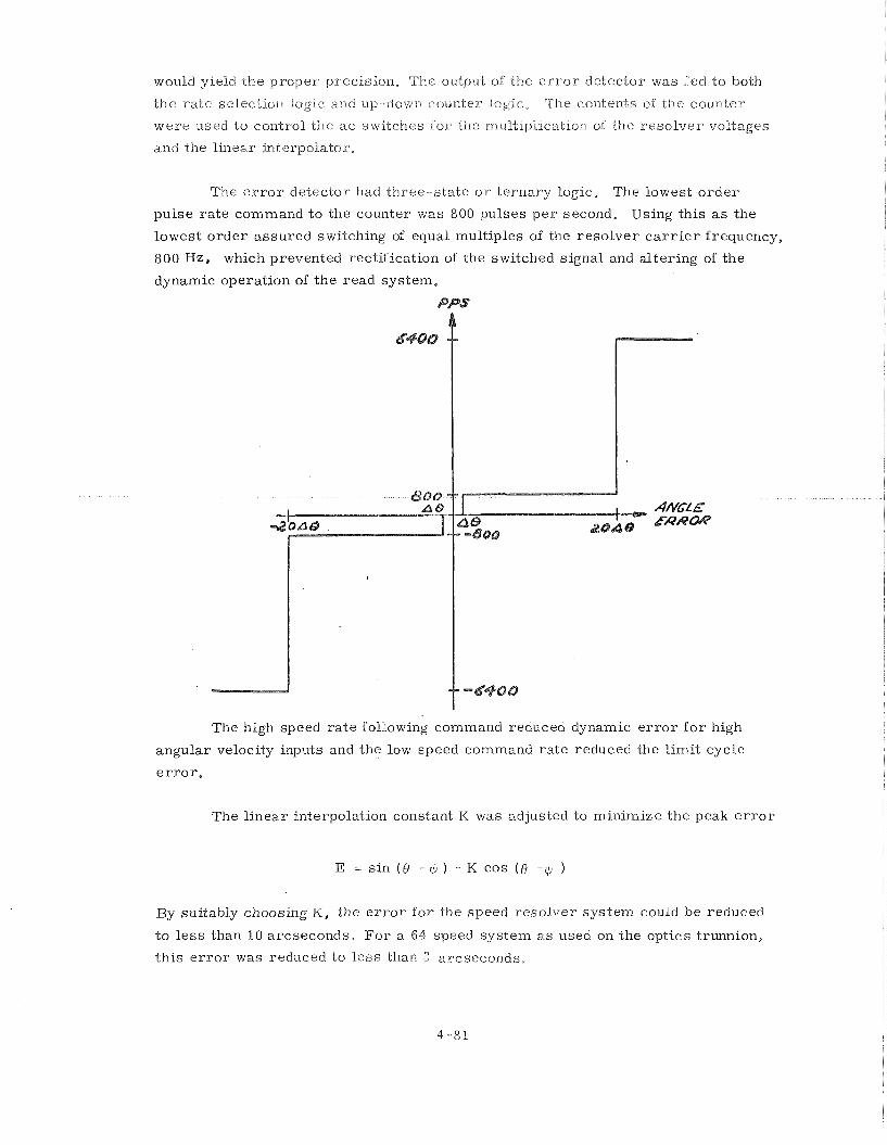
would yield the proper precision, The output oi the e r r o r detector was fed to both
the r a t e selection logse and up-down counter logic, The contents of the counter
were used to control the a c swlteiles fo r the rnuitlpl~catron of the reso lve r voltages
and the l inear interpolator.
The e r r o r detector had three-s ta te o r ternary logic. The lowest o r d e r
pulse ra te command to the counter was 800 pulses p e r second. Using this a s the
lowest o rde r assured switching of equal multiples of the resolver c a r r i e r frequency,
800 Hz, which prevented rectification of the switched signal and al tering of the
dynamic operation of the read system.
The high speed ra te following command reduced dynamic e r r o r f o r high
angular velocity inputs and the low speed command ra te reduced the l imit cycle
e r r o r ,
The l inear interpolation constant K was adjusted to minimize the peak e r r o r
E = sin ( 6 - $ ) - K cos (6 - $ )
By suitably choosing K, the e r r o r f o r the speed resolver sys tem could be reduced
t o l e s s than 10 arcseconds. F o r a 64 speed system a s used on the optics trunnion,
th is e r r o r was reduced to l e s s than 2 arcseconds,
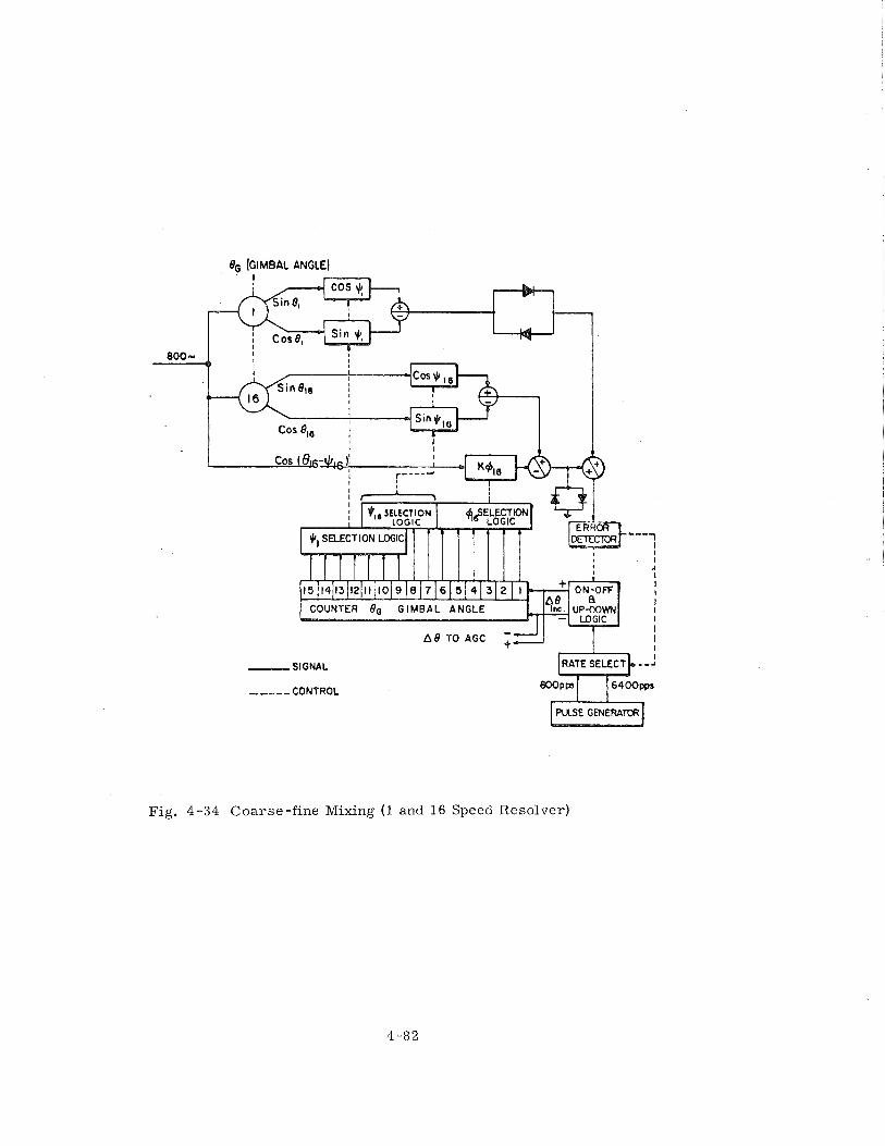
8, (GIMBAL ANGLE)
S I G N A L
,,---CONTROL
Fig. 4-34 Coarse-fine Mixing (1 and 16 Speed Resolver)
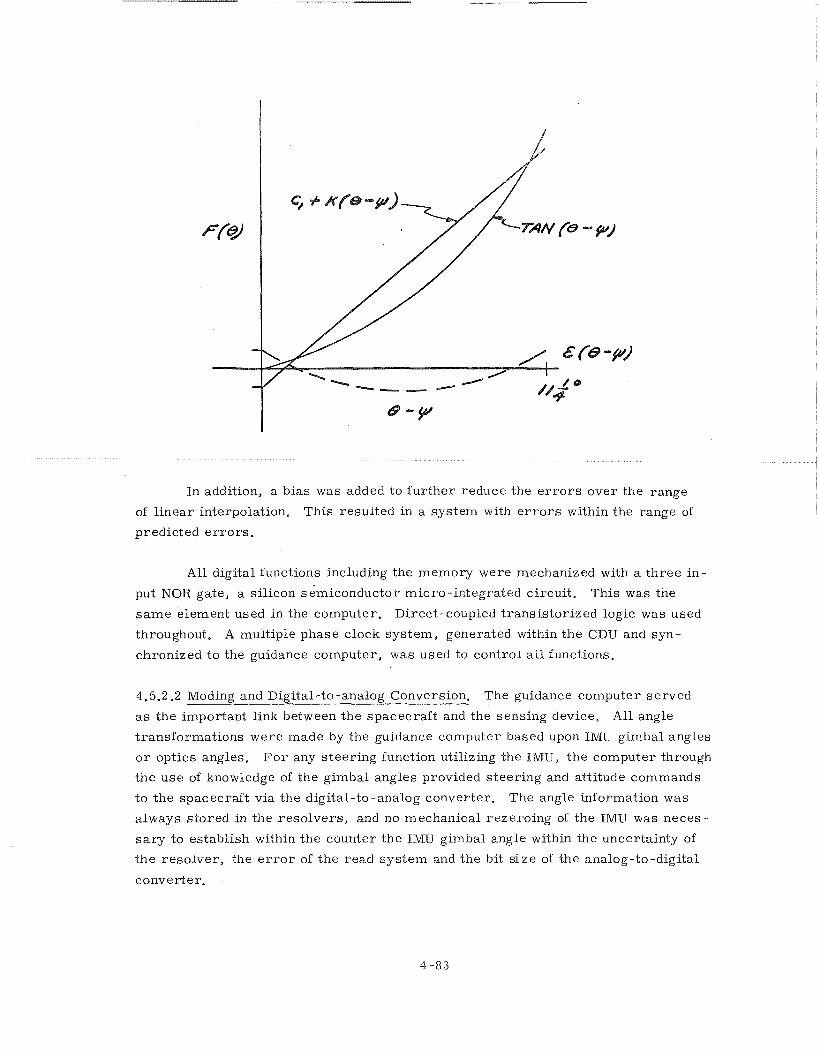
In addition, a bias was added to fu r the r reduce the e r r o r s over the range
of l inear interpolation. This resulted in a system with e r r o r s within the range of
predicted e r r o r s .
All digital functions including the memory were mechanized with a th ree in-
put NOR gate, a silicon s emiconductor m i c r o -integrated circuit . This was the
s a m e element used in the computer. Direct-coupled t rans is tor ized logic was used
throughout. A multiple phase clock sys tem, generated within the CDU and syn-
chronized t o the guidance computer, was used to control a l l functions.
4,5.2,2 Moding and Digital-to-analog Conversion. The guidance computer served -- ---- a s the important link between the spacecraf t and the sensing device. All angle
transformations were made by the guidance computer based upon IMU gimbal angles
o r optics angles. F o r any s teer ing function utilizing the IMU, the computer through
the use of knowledge of the gimbal angles provided s teer ing and attitude commands
to the spacecraft via the digital-to-analog converter . The angle information was
always stored in the resolvers , and no mechanical rezeroing of the IMU was neces-
s a r y to establish within the counter the INIU gimbal angle within the uncertainty of
the resolver , the e r r o r of the read sys tem and the bit s i ze of the analog-to-digital
converter .
The digital-to-analog converter syskem was required to accept digital com-
vnands froin the guidance computer and generate analog voltages ( a c and dc )
proportional to these commands. The e r r o r angle cou-nter was an eight bit up-down
counter. Computer commands were stored in this countei-. The counter was
logically controlled to prevent it f r o m being r e s e t to zero in the event it was com- 9 manded to m o r e than 10 increments. The analog e r r o r signals were developed by
a n 800-Hz source gated by the counter contents through a res is tance ladder to the
input of a n operational amplif ier . F o r polarity, r eve rsa l by switching was used t o
command the 0 phase o r n phase 800-Hz input to the ladder. All analog voltages
used a s s teer ing commands to the LEM, Spacecraft o r other portions of the Apollo
launch vehicle were dc-isolated f r o m the guidance sys tem, ei ther by t r ans fo rmers
o r an isolated demodulator,
The moding of the system was almost entirely controlled by the computer.
Provision was made f o r two modes to be controlled by the astronaut. One mode was
the cage function. In the event of a spacecraft tumble and loss of attitude, provision
was made f o r the astronaut to cage the IMU gimbals with respect t o the spacecraft
af ter he has f i r s t stabilized the craft. This then gave him a means of obtaining a
new reference in a very shor t time. The other manual mode was s i m i l a r in that
with the computer not operating he could use the s a m e switch to cage the IMU with
respect to the spacecraft , r e l ease it, and again use the IMU a s an attitude reference,
In all. other iner t ia l subsystems, moding was controlled by the computer.
There were a number of interesting modes possible because of the flexibility of the
CDU. The Coarse Align Mode, that of commanding the IMU gimbal angles by the
resolvers , was r a t e controlled to limit angular velocity input to the gyroscopes.
The input to the e r r o r detector was summed with the analog command f rom the
computer to provide s table operation. The gimbal angle pulse increments f rom the
read sys tem were used as feedback pulses to the e r r o r angle counter.
4. 5. 3 CDU Problems
4.5.3.1 Block I Problems. - The problems associated with the Block I CDU were of
a mechanical nature. The gear t r a ins used with the CDU exhibited excessive wear,
and a few units "froze" in operation. To c o r r e c t this fai lure mode, a carefully
selected lubricant was added to the gears . Another gear box associated fai lure was
with the motor tachometer supplied by one of the two vendors of this component.
Because of mechanical tolerances, i t "froze" a t elevated temperatures . The c o r -
rective action f o r this fa i lure was to select the motor-tachometer f rom the vendor
whose product did not exhibit th is fai lure mode.
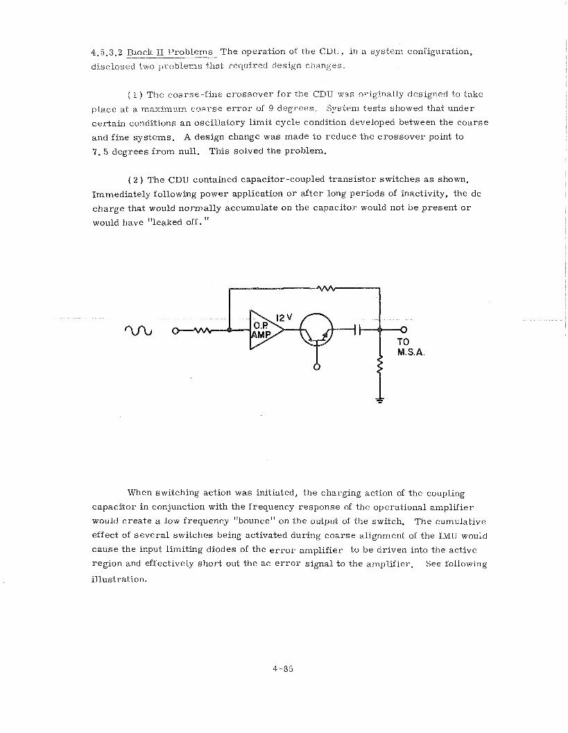
4-5.3.2 Block II Problems The operation of the CDU, in a sys tem configuration, -- disclosed two problems that required design changes,
( 1 ) The coarse-f ine c rossover f o r the CDU was originally designed to take
place at a mzximum c o a r s e e r r o r of 9 degrees , System tes t s showed that under
cer ta in conditions a n oscil latory l imit cycle condition developed between the coarse
and fine sys tems, A design change was made to reduce the c rossover point to
7 . 5 degrees f r o m null. This solved the problem.
( 2 ) The CDU contained capacitor -coupled t r ans i s to r switches a s shown.
Immediately following power application o r af ter long periods of inactivity, the dc
charge that would normally accumulate on the capacitor would not be present o r
would have "leaked off. I '
When switching action was initiated, the charging action of the coupling
capacitor in conjunction with the frequency response of the operational amplif ier
would c rea te a low frequency "bounce" on the output of the switch. The cumulative
effect of severa l switches being activated during coarse alignment of the IMU would
cause the input limiting diodes of the e r r o r amplif ier to be driven into the active
region and effectively shor t out the ac e r r o r signal to the amplifier. See following
illustration.
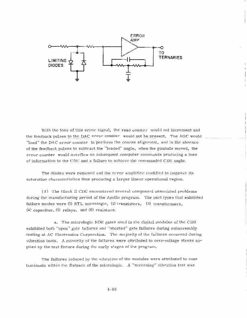
i RNARIES LIMITING DIODES
-
With the l o s s of this e r r o r signal, the read counter would not increment and
t I
of the feedback pulses to subtract the "loaded" angle, when the gimbals moved, the
e r r o r counter would overflow on subsequent computer commands producing a l o s s
of information to the CDU and a failure t o achieve the commanded CDU angle.
The diodes were removed and the e r r o r amplifier modified to improve i t s
saturation character is t ics thus producing a l a r g e r l inear operational region.
( 3 ) The Block I1 CDU encountered severa l component associated problems
during the manufacturing period of the Apollo program. The part types that exhibited
fai lure modes were (1) RTL micrologic, (2) t r ans i s to r s , (3) t r ans fo rmers ,
(4) capacitor, (5) re lays , and (6) r e s i s to r s .
a. The micrologic NOR gates used in the digital modules of the CDU
exhibited both "open" gate fai lures and "shorted" gate fai lures during subassembly
testing a t AC Electronics Corporation. The majori ty of the fai lures occurred during
vibration tes ts . A minority of the fai lures were attributed to over-voltage s t r e s s ap-
plied by the t e s t fixture during the ear ly s tages of the program.
The fai lures induced by the vibration of the modules were attributed to con-
taminants within the flatpack of the micrologic. A "screening" vibration t e s t was
conducted at the module manufacturer to remove this mode of failure. The vibration
"screening" vibrated the micrologic flatpacks along th ree perpendicular axes.
b. The t r ans i s to r used in the CDU ac switches was a 2N2351 device.
During the program this t r ans i s to r exhibited failure modes that were attributed to
the "purple plague" and to internal contamination. The corrective action taken was
to institute a centrifuge and X-ray inspection for incoming t r ans i s to r s at AC Elec-
t ronics and to improve cleaning procedures at the manufacturer 's facility. A second
source of supply was a lso obtained for pa r t s procurement.
c. Trans fo rmer fai lures occurred via two different modes. The Bush
t r ans fo rmer (1010724) used i n the main summing amplifier exhibited inductance shifts
a f t e r potting the module. The inductance shift was found to be the resul t of lamina-
tion shifts within the t ransformer . This condition was corrected by an improved
method of sealing the laminations.
The other mode of t r ans fo rmer fai lure was associated with wire breakage in-
t e rna l to the UTC t rans fo rmer . The wire s i ze used to wind these t r ans fo rmers was
rminations and the fine wire
y the hard potting compound
used in the t r ans fo rmer . The correct ive action was to replace the t ransformer with
a compatible unit wound with l a r g e r wire.
d. ~ a i l u r e modes of the capacitors used in the CDU were associated
with two types of capacitors. One capacitor exhibited high leakage character is t ics
af ter potting i n a module and after being subjected to vibration testing. This fai lure
mode was found to be predominantly associated with a capacitor from one manufac-
t u r e r (Kemet). The corrective action was not to use this product in the construction
of the CDU. The other capacitor was .a polystyrene film unit. This capacitor ex-
hibited film rupture result ing in shorted units and poor connections to the film for
external leads. The correct ive action was to replace the polystyrene unit with a
Mylar capacitor.
e . The re lays used in the CDU for DAC output t r ans fe r s were type
SCD1010353-7. Contamination of the relay by solder balls produced fai lures of these
units in the initial s tages of CDU manufacturing. Subsequent tightening of the inspec-
tion procedure by the manufacturer removed th is failure mode a s a problem.
f. Fai lures associated with res i s to r s were confined to the high res i s -
tance value metal f i lms and the carbon r e s i s t o r s used in the main summing ampli-
f iers . The metal f i lm r e s i s t o r s were found to be changing values under module
rework. It was concluded that the abras ive mater ia l used during depotting was
establishing a high electrostat ic voltage on the r e s i s t o r s and in tu rn punching through
and /o r changing i t s metal film character is t ics . The corrective action was to change
the type of abras ive mater ia l used during the depotting process .
The carbon res i s to r s , of which the re were only two in each CDU axis, ex-
hibited a drift character is t ic upon potting that forced the associated res is tance value
to fal l outside the specified l imits . The correct ive action for th is phenomenum was
to change the specification to accommodate the drift. These r e s i s t o r s occupied a
noncritical position in the function of the CDU; hence, the specification variance
could be tolerated.
4. 6 Electronics Packaging
4. 6.1 Constraints on Packaging Design
The G&N electronic packaging design evolved a s the resul t of compromises
among conflicting constraints. Besides the principal goal of achieving required
performance within the operational environment, the impact of schedule, weight,
reliability, cost, power drain, producibility, and logist ics were al l considered.
The constraint of schedule affected both design and design evaluation. Schedule re -
quirements dictated the ea r ly re lease of the design to production. Functional, me-
chanical and the rmal design evaluation of prototype hardware in the expected environ-
ment occurred simultaneously with ear ly production. Necessary design modifications
result ing f rom the evaluation were somet imes incorporated a s r epa i r fixes.
Fac to r s which had p r imary influence in the packaging design were the space-
craft environment and interface constraints, and for Block I, the requirement for in-
flight diagnosis and module replacement.
4. 6. 2 Interface Control Documents
Spacecraft constraints were defined in Interface Control Documents (ICD).
The ICDS affecting the package design defined volume envelopes, weight require-
ments, the rmal interfaces, mounting arrangements, acceleration, vibration and
shock environments, ma te r i a l compatibility, and color and markings. The ICDs
developed a s the G&N and spacecraft designs matured. Ear ly g r o s s interface defi-
nitions were refined with occasional design modifications on both s ides of the inter-
faces to accommodate other associated designs.
The requirement for inflight maintena-nce was a consequence of the high re-
liability requirements imposed by NASA on all the Apollo contractors. Since the
fai lure r a t e s of the high reliability components for Apolio had yet to be determined,
the conservative approach was to provide for inflight maintenance.
Block I experience, however, showed that the required overall reliability
could indeed be rea l ized without resor t ing to inflight maintenance. This require-
ment was therefore removed for the Block I1 command module and LM G&N systems.
4. 6. 4 Materials Testing
NASA and a l l contractors had been doing extensive flammability, toxicity, out - gassing, and odor testing of mater ia ls in accordance with NASA "Procedures and Re-
quirements for the Evaluation of Space Nonmetallic ~ a t e r i a l s " MSC-A-D-66-3. As
a resul t of these tes ts , many engineering mater ia ls were banned f rom use within the
spacecraft if they were to interface with the cabin atmosphere. Also, in Block 11, a
great emphasis was placed on avoiding the use of flammable mater ia ls . These con-
siderations led to the decision t o package the equipment, whenever possible, into
sealed metal containers. Because the Block I1 and L M inert ial subsystems were
functionally identical, an attempt was made to use common equipment wherever pos-
sible in the two sys tems.
4.6.4.1 Corrosion Protection & Associated Design Restraints. - The extensive use of
magnesium in the s t ructura l members of the Apollo airborne electronic assembl ies
introduced the possibility of ser ious corrosion problems that required solution.
There were cer ta in parameters common to all the assembl ies that tended to com-
pound the problem when considering methods of protecting the equipment against
corrosion. In addition to basic protection, the requirements for both the Block I1
CM and LM finish sys tems were: (1) electr ical grounding, ( 2 ) thermal t ransfer , and
(3) outgassing. A fourth consideration, for LM assembl ies only, was emissivity.
Hard vacuum [vacuum below the level of l o m 6 m m Hg (torr)] affects ma te r i a l s
in two general ways: Fi rs t , the mater ia l contains adsorbed and absorbed gasses
which may be removed by outgassing. Secondly, vaporization o r sublimation of the
mater ia l o r of a volatile (o r toxic) component of the mater ia l may occur. The r a t e s
of these reactions can be radically affected by temperature. The amount and nature
of potentially toxic and objectionable products outgassing f rom crew bay mater ia ls
were evaluatedand analyzed to insure astronaut safety and well-being for optimum
mission performance. The outgassing concentration of individual contaminants was
related to the effective habitable spacecraft volume, In general, mater ia ls that
outgassed organic substances in excess of 100 ppm per weight of sample was con-
sidered unacceptable for use in manned spacecraft crew bay a reas .
l'he selection of organic mater ia ls fo r corrosion protection was evaluated
and considered acceptable in t e r m s of outgassing character is t ics .
Outgassing products f rom the modules were entrapped i n the hermetically
sealed containers. Outgassing contaminants f rom the wire-wrap side of the headers
were minimized since this was the side that mounted directly to a coldplate and/or
spacecraft s t ructure .
4.6.4.2 Required Surface Treatments. Electr ical bonding of the PSA, PEA, PTA,
and CDU to spacecraft s t ructure was accomplished by using a spotface under mounting
screwheads a s an e lec t r ica l conductive path. The engaged threaded section of the
mounting sc rew completed the path to the spacecraft s t ructure ground. Thus elec-
t r i c a l currents were flowing through the case to the S IC s t ructurevia a dissimilar
meta l path. The total number of electronic assembly mounting sc rew fas teners was
analogous to
s t ructure ele
were an inherent part of the design, and the only means of controlling galvanic cor-
rosion was to exclude mois ture f rom the mated metal surfaces. The solutions for
the various assemblies were a s follows:
(1) CM PIPA Electronics Assembly (PEA) -- A stepped, rubber gasketed
ir idi te aluminum washer was used under the cover screws, o r a s an alternate,
the DOW 19 spotface was coated with an RTV-108 after assembly of the cover-
to-header screws.
( 2 ) CM Power and Servo Assembly (PSA) -- The counterbores in the cover
were filledwith an RTV-108 after assembly.
( 3 ) CM and LM Coupling Data Unit (CDU) -- (a) The cover screws and nuts,
after assembly of the two halves, were coated with RTV-108; (b) the lower
washer, which was under the captivated header-to-structure mounting sc rew
head, was bonded in place. The adhesive surrounded the washer periphery,
masking the Dow- 19 magnesium surface. Epon 919 was used a s an adhesive.
( 4 ) LM Power Servo Assembly (PSA) - - (a) A stepped, rubber gasketed
ir idi te aluminum washer was used under the cover sc rews ; (b) a thin bushing
sleeve was bonded to the magnesium in the precessed wells.
(5) LM Pulse Torquing Assembly ( P T A ) -- Same a s itern ( 4 ) .
The electronic assembl ies required a means of dissipating generated heat.
The modules t r ans fe r red heat to the assembly header which in turn transmitted heat
to a coldplate heat exchanger o r the spacecraf t s t ructure . The assembly-to- coldplate
o r s t ruc tu re interface surfaces were Dew-17 magnesium with zinc chromate p r i m e r
(MIL-P- 8585) and 3M 400 polyurethane paint (SCD 1012543) (per ND1002291).
Total p r i m e r and paint thickness was 2 mi ls maximum. A coating was r e -
quired on these magnesium surfaces, fo r the mating surface was alodine aluminum.
This meant that the rmal hot and cold spots would have condensed water, creating a
corros ive galvanic couple. This coating reduced the thermal t r ans fe r efficiency
when compared to an unpainted interface, but i t was within the l imi ts to maintain
sufficient cooling even in a vacuum environment. This was partially accounted fo r
by the application of DC-340 thermal g rease to the assembly mounting interface fo r
the CM and the application of alumina-filled RTV-601 for the LM.
External surfaces, with the exception of heatsink surfaces of actively cooled
electronic assembl ies in the LM, possessed an infrared emittance of 0.40 o r l e s s
in the region of the electromagnetic spectrum between 5 microns and 35 microns.
This was a requirement for thermodynamic equilibrium in the LM. A number of
finishes were evaluated using an emissometer , and i t was determined that an alumi-
num filled epoxy paint developed by MIT/IL provided an emittance value around 0. 30
when applied on Dow -17 magnesium.
The specific requirements for Apollo electronic equipment with regard to low
emissivity, outgassing, thermal conductivity, EM1 shielding and corros ive environ-
ments led to studies in these specific a reas . It is beyond the scope of this r epor t
to describe a l l the surface treatments, conversion coatings, organic coatings, o r
any combination of these t rea tments that were tested. The selection of the combination
of t rea tments and coatings a s detailed in preceding paragraphs was the most compat-
ible with the exposure medium.
4. 6. 5 Block I PSA Design
The Block I Power and Servo Assembly (PSA) contained al l the electronics
for the ISS except for a few modules located in the IMU and CDUs. The PSA also
contained most of the electronics for the optical subsystem. It consisted of ten
nickel-plated magnesium alloy t rays , each containing a number of replaceable mo-
dules. There were a total of ninety modules in the ten t r ays . Each t r a y had a lo-
cating tongue that fitted into a groove in the PSA end connector assembly to insure
proper alignment of e1ec;trical connectors. 'The tapered tong~re also helped to main-
tain physical contact between the base of the t ray and the the rmal interface mater ia l
which t ransmit ted heat to the spacecraft coldplate. On the front of each t r a y was a
t e s t connector, guide pins to locate the t r ay and a captive fastening screw used to
jack the PSA into place. A stiff metal s t r ip , called a toe plate was fastened to the
spacecraft s t ructure and provided support for the front end of the t r ays . The fas-
tening s c r e w s bolted into the toe plate. The modules plugged into feedthrough con-
nectors on the vert ical wall of the t r a y and were held in place with mounting screws.
Intra-tray wiring was done on the other side of the vert ical wall. The wiring
was encapsulated with polyurethane. Moisture protection of the tes t connectors was
provided by individual gaskets and connector covers. Figure 4-35 shows a typical
tray.
The PIPA and IRIG calibration modules contained selected components which
were matched specifically to a single IMU. It therefore appeared advisable to pack-
age these electronics in a separa te sealed PSA when the IMU was changed. This as-
sembly was called the PIPA Electronics Assembly (PEA) in the command module
and the Pulse Torque Electronics (PTE) in the LM. The Block I1 and LM electronics
CDUs were identical except that two coarse align modules were not needed in the
CM CDU and therefore were not plugged in.
4. 6. 6 Block I1 and LM Electronics
The Block 11 and LM electronics consisted of one CDU, one PEA o r PTE,
and one PSA. The PSA for the command module also contained the electronics for
the optical subsystem. There were no OSS electronics in the L M PSA.
The Block I1 and LM PSAs, PEA, and P T E were al l basically s imi lar in
package design. Each contained a machined header to which the modules were at-
tached on one side, while the r e v e r s e side contained the inter-module wiring and
output harnessing. A s t ructura l cover and gasket were bolted to the header on the
module side to provide a hermetic seal . All electr ical connections to these assem-
blies were through sealed connectors. Each assembly contained a slight positive
p r e s s u r e using an iner t gas with a helium t race . The wiring was sealed by a solid
polyurethane encapsulant.
The CDU for Block I1 and LM contained two separa te header assemblies.
The long modules mounted a c r o s s the width and bolted into the header. The two
headers were bolted together with modules back to back. A gasket between the
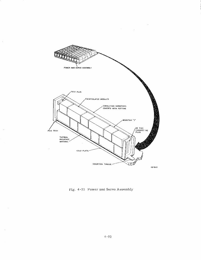
ENCAPSULATED MODULES
CONNECTING HARNESSES COVERED WITH POTTING
MOUNTING " T "
COLD P L A T t
INSERTION TONGUE
Fig. 4-35 Power and Servo Assembly
headers provided a hermet ic seal . In this configuration, the wiring planes were on
the outside and sealing was provided by a solid polyurethane encapsulant. Light
sheet meta l covers provided mechanical protection for the encapsulation. The CDU
was pressurized slightly above one atmosphere using an iner t g a s with a slight helium
t race .
The gasket s e a l s provided a near hermet ic seal for the electronic packages
and prevented leakage to levels below standard cc / s e c of helium ac ross a one
atmosphere p r e s s u r e differential. A sea l of this quality significantly limited the
outgassing of toxic and malodorous mate r i a l s f rom inside the sealed assembly and
offered positive protection of the unit f r o m mois ture environment. The integrity of
the seal could be 100% tes ted at the factory o r i n the field.
4. 6. 7 Module Design
Module design remained essentially s imi la r between Block I and Block 11.
The module was the lowest o r d e r replaceable unit. In o r d e r to obtain the utmost
in reliability, the proven welded cordwood module was utilized. This configuration
was used throughout the ISS in the Gimbal Mounted Electronics, the Power and Servo
Assemblies, and the PIPA Electronics.
In lower heat dissipating circuits , the cordwood components were mounted
between two epoxy fiberglass wafer boards and interconnected by welding. This as-
sembly was then mounted i n an aluminum (Block I) o r magnesium (Block 11) frame,
welded to the output pins and foam-encapsulated.
Generally, any module over 10 Watts heat dissipation utilized an aluminum o r
magnesium heatsink. These were tape control machined t o receive component pa r t s
and output connectors in cordwood fashion. Point-to-point welded interconnections
were made on both s ides of the module. After the module was tested electrically and
inspected, the module was then encapsulated with foam potting.
The design of the CDU digital modules was dictated by the l a rge number of
integrated circuit flatpacks in this assembly. The CDU modules were long and nar-
row consisting of two fabricated interconnection matr ices to which the flatpacks were
bonded. The interconnection matr ices were in tu rn bonded to a r i b in the magnesium
module header and connected to the output pins. Each matr ix was built up of l a y e r s
of etched meta l conductors and Mylar insulators. The flatpacks were then welded to
the conductors. CDU modules with analog components were of the same shape a s
above but with the heatsink machined to receive cordwood components.
lVIodule geometry was derived by evaluating the following considerations:
(1) function, ( 2 ) reliability, ( 3 ) repairability, and (4) producibility. Experience in-
dicated that the functional circuit, a s breadboarded and schematically drawn by the
circuit designers, was very often the best compromise. Normally, package design
affects the initial schematic only when the available volume is too small .
Depending upon the geometry of the module, two, three, or four sc rews in
the f r a m e held the module i n place. These mounting screws were usually captivated
sc rews that allowed the module to be mounted into place o r dejacked. The CDU
modules had two mounting and dejacking screws, one at ei ther end.
Insertion of the module into the header connector was blind. Since the re was
some danger that the pins would be slightly bent o r broken, hard meta l alignment
pins were used to guide the insert ion of the module with proper connector pin align-
ment. When the module was not inser ted i n a header, a shielding sk i r t was provided
to protect the male connector pins.
EM1 bonding of all analog modules in the electronic packages was provided by
a s t ructura l ground on the modules that consisted of a s ta in less steel pin mounted i n
a spotfaced-tapped hole in the module f rame connected to an output pin.
4. 6. 8 Connector Design
The Apollo sys tem connector was the Malco "Mini Wasp. " It was a tuning fork
fr ict ion connector with a nylon insulator and mounted on 0. 125"centers. The electronic
modules of a l l the packaged hardware were interconnected by means of Malco pins that
were se t into the module housing and mated with pins in the header s t ructure . In gen-
e ra l , the module was fitted with a male connector pin and the header o r t r a y used the
female pin. The male pin had a nickel base with a 0. 000050 inch minimum gold-
plating. This metallurgy was selected because it offered the best combination of
desirable character is t ics , namely: (1) corros ion resistance, (2) low surface r e s i s -
tance, and (3) compatibility with res is tance welding. The female connector could be
described a s a wrappost with a beryllium-copper base, 0.000200 s i lver plate, and a
final plate of 0.0000 50 minimum gold. The female wrappost was compatible with the
mechanical wirewrap process .
The c r i t e r i a used for evaluation of terminations, i. e . , soldering welding,
wirewrapping, o r crimping were: (1) reliability, including joint life with respect to
mechanical integrity and contact res is tance , ( 2 ) compatibility with s t ructure and i t s
dynamic environment, (3) interconnection density required, (4) ease of repairability,
and (5) t ime, skill and tooling required to make the termination.
In Block I, the module-to-tray connectors were environmentally sealed by
individual module gaskets. M'hen the inflight module replacement requirement was
dropped, the environmental sea l was supplemented by the application of Dow Corning
DC-4 silicone g rease around the connector pins. In Block 11 and LM the module-to-
header interfaces were wholly within the sealed packages and required no additional
environmental protection. During system installation into the spacecraft, all G&N
external interface connectors had a l ibera l amount of DC-4 g rease applied to the pins
to aid in excluding mois ture .
4. 6. 9 Thermal Design
4. 6. 9.1 General Considerations. The thermal aspects of the electronics packaging
were concerned with the removal of heat from the modules. This was accomplished
by providing a the rmal conductive path f rom the modules to spacecraft-supplied cold-
plates. The coldplates were of an internal pin design sandwiched between two 0. 020
inch thick plates. A water glycol solution, maintained between 3 2 ' ~ and 55OF, was
circulated through the coldplates. Typical thermal res is tances f rom coldplates to 2
coolant were on the o r d e r of 3. 5 O F I ~ a t t l i n .
4. 6. 9. 2
modules mounted to a ver t ica l member of a removable t ray . The requirement for
inflight maintenance, with the requirement of handling the modules and t rays , pre-
cluded the use of the rmal conductive grease between the PSA t rays , and the coldplate.
Consequently, North American developed a thermal interface mater ia l consisting of
a rubber-like tubing (118 inch OD) with a copper foil helically wound on the outside.
This mater ia l was laid side by side to fo rm a mat and was placed between the cold-
plate and the PSA. Late in the Block I program, the inflight maintenance require-
ment was abandoned and a thermally conductive grease , Dow Corning DC-340, was
used in conjunction with the thermal interface mater ia l to effect a better heat t ransfer .
Figure 4-36 sl-iows a typical component mounting method and the res is tances
considered in the the rmal analog. A nodal network was written for each t ray , which
included spreading within the t r ay down to the coolant. Solving this network gave the
component temperature . For high component reliability, junction of silicon devices
were not allowed to exceed 105 '~ . These measures insured control of the interface
temperature a t the t r a y base with NAA to not exceed cer ta in temperature l imi ts .
These l imi ts varied f rom 90°F to 1 2 0 ' ~ for the ten t r a y s that comprised t h e Block I
PSA.
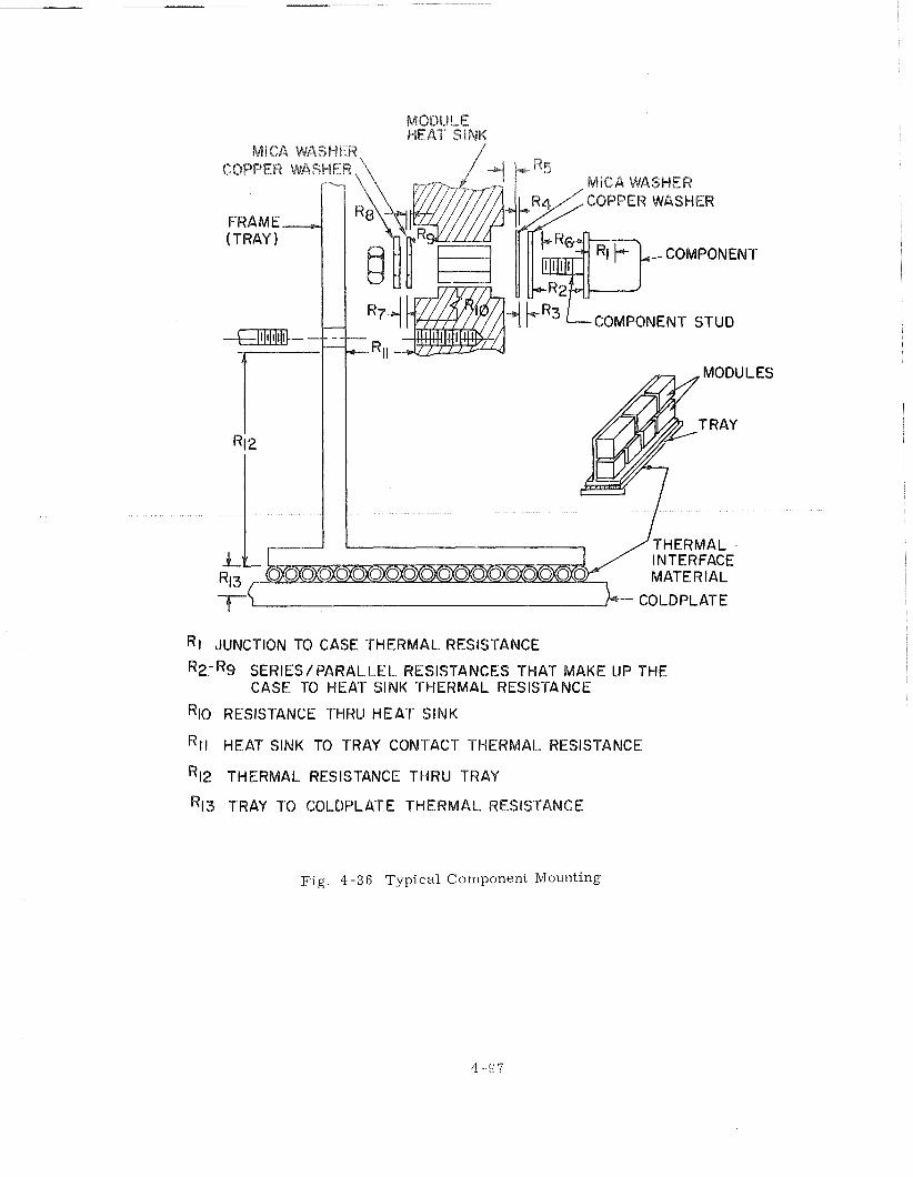
MODULE HEAT SINK
MICA WASHER, /
INTERFACE MATERIAL
T! b-- COLDPLATE
Rl JUNCTION TO CASE THERMAL RESISTANCE
R2-R9 SERIES/PARALLEL RESISTANCES THAT MAKE UP THE CASE TO HEAT SlNK THERMAL RESISTANCE
RIO RESISTANCE THRU HEAT SlNK
R~~ HEAT SlNK TO TRAY CONTACT THERMAL RESISTANCE
R12 THERMAL RESISTANCE THRU TRAY
R~~ TRAY TO COLDPLATE THERMAL RESISTANCE
JLES
Fig. 4 -36 Typical Component Mounting
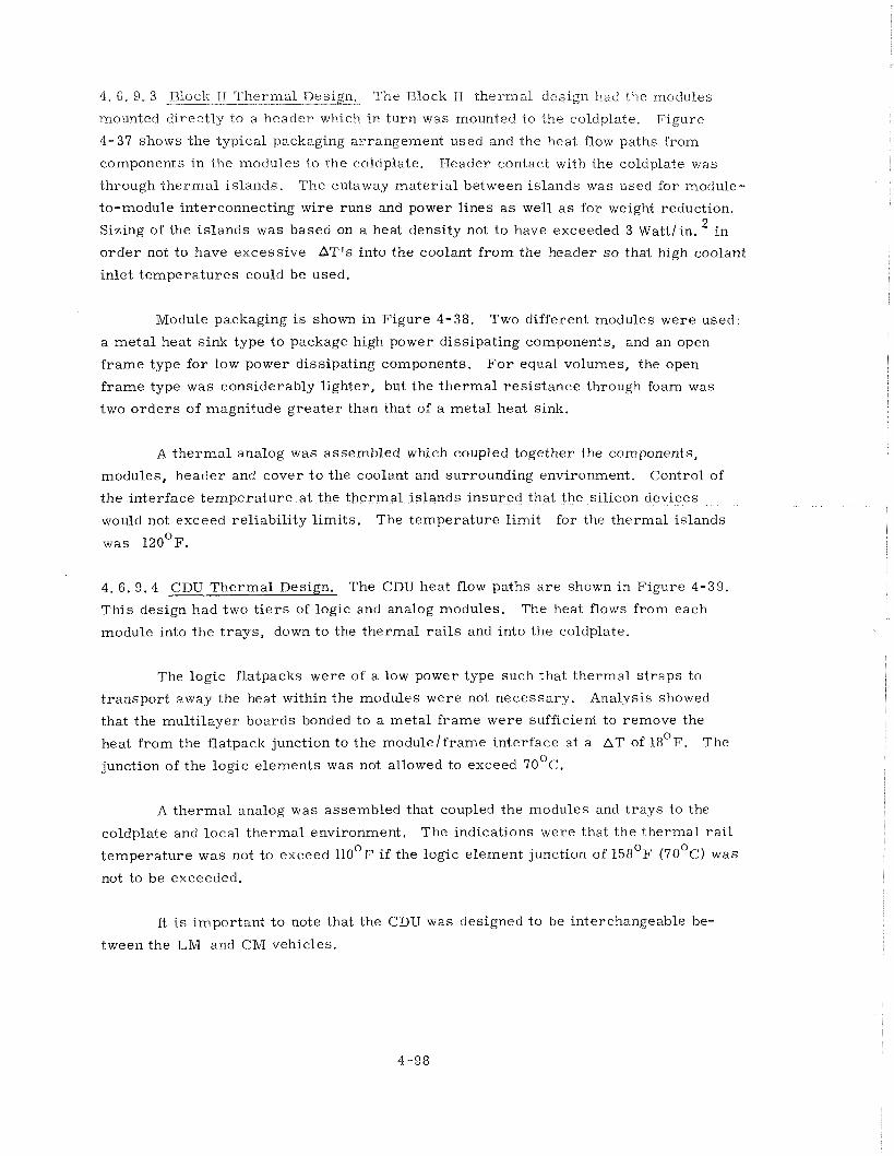
4. 6 . 9. 3 Block 11 Thermal - . The Block I1 the rmal design had the modules
mounted directly to a header which in tu rn was mounted to the coldplate. Figure
4-37 shows the typical packaging arrangement used and the heat flow paths from
components in the modules to the coldplate. Header contact with the coldplate was
through the rmal islands. The cutaway mater ia l between islands was used for module-
to-module interconnecting wire runs and power l ines a s well a s for weight reduction.
Sizing of the islands was based on a heat density not to have exceeded 3 Wattlin. i n
o rde r not to have excessive AT'S into the coolant f r o m the header s o that high coolant
inlet t empera tu res could be used.
Module packaging i s shown in Figure 4-38. Two different modules were used:
a meta l heat sink type to package high power dissipating components, and an open
f rame type for low power dissipating components. F o r equal volumes, the open
f rame type was considerably lighter, but the the rmal res is tance through foam was
two o r d e r s of magnitude g rea te r than that of a metal heat sink.
A the rmal analog was assembled which coupled together the components,
modules, header and cover t o the coolant and surrounding environment. Control of
the interface temperature at the thermal islands insured that the silicon devices
would not exceed rel iabil i ty l imits . The temperature l imit for the thermal islands
was 120°F.
4. 6. 9 .4 CDU Thermal Design. The CDU heat flow paths a r e shown in Figure 4-39.
This design had two t i e r s of logic and analog modules. The heat flows from each
module into the t r ays , down to the thermal r a i l s and into the coldplate.
The logic flatpacks were of a low power type such that thermal s t r aps to
t ranspor t away the heat within the modules were not necessary. Analysis showed
that the mult i layer boards bonded to a metal f rame were sufficient to remove the
heat f rom the flatpack junction to the modulelframe interface at a AT of 1 8 ' ~ . The
junction of the logic elements was not allowed to exceed 7 0 ' ~ .
A the rmal analog was assembled that coupled the modules and t r ays to the
coldplate and local the rmal environment. The indications were that the thermal r a i l 0
temperature was not to exceed 1 1 0 ' ~ if the logic element junction of 1 5 8 ' ~ (70 C) was
not to be exceeded.
It is important to note that the CDU was designed to be interchangeable be-
tween the L M and CM vehicles.
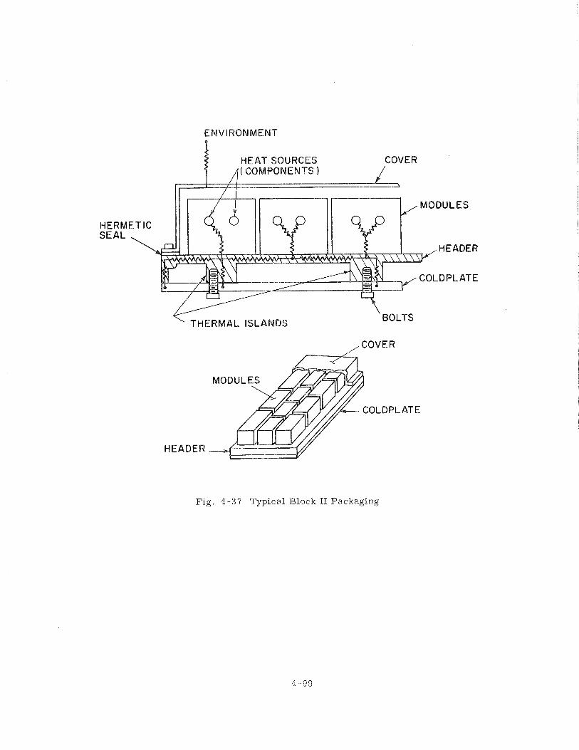
ENVIRONMENT P
HEAT SOURCES /I( COMPONENTS
THERMAL ISLANDS
COVER
HEADER
Fig. 4-39 Typical Block II Packaging
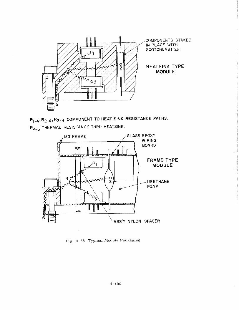
COMPONENTS STAKE IN PLACE WITH SCOTCHCAS"T221
HEATSINK TYPE MODULE
R I - ~ , R2-4, R3-4 COMPONENT TO HEAT SINK RESISTANCE PATHS.
R4 -5 THERMAL RESISTANCE THRU HEATSINK.
BOARD
FRAME TYPE MODULE
, URETHANE FOAM
SPACER
Fig. 4-38 Typical Module Packaging
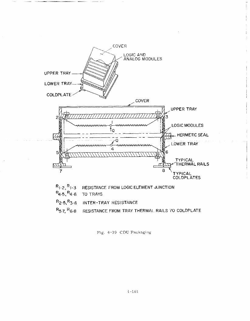
LOGIC AND ANALOG MODULES
, COVER
LOGIC MODULES
HERMETIC SEAL
7 COLDPLATES
R1-2, 1-3 RESISTANCE FROM LOGIC ELEMENT JUNCTION
%-5, R 4 ~ TO T R N S
R2-5,R3-6 INTER -TRAY RESISTANCE
R5-7, R6-8 RESISTANCE FROM TRAY THERMAL RAILS 7 0 COLDPLATE
Fig. 4-39 CDU Pacltaging
The automatic wirewrap process was utilized f o r the single plane header.
Because of wire densit ies, the high reliability automatic interconnection scheme was
suited to producibility and repairability. The lengths of the wires in each header
caused some concern since they were a source of coupled noise where wires r a n
parallel for a finite length. The lengths and routing of the wires were determined
by a computer program. The only res t r ic t ions placed on the program were those
inherent in the wiring patterns available with the Gardner-Denver automatic machine.
4. 6.10 Packaging Prob lem
(1) A major mechanical difficulty in the Block I PSA was to achieve an ade-
quate thermal interface between the PSA t rays and the spacecraft coldplate. Tes t s
of the the rmal interface mater ia l showed that thermal conductance varied in direct
proportion to the depth of i t s compression. Other t e s t s indicated that the p ressures 2 required to deflect the mater ia l to achieve the desired conductance (100 ~ ~ u / h r / O ~ / f t )
were much higher than originally anticipated. These forces caused bowing at the
t r a y s and plate, thereby reducing conductivity a c r o s s local a r e a s on the interface.
Closer to lerances for the t r a y locating tongues, stiffening of the t rays , and changing
the toe plate f r o m
However, i t was no
mitting the use of conductive g rease on the the rmal interface material , was the prob-
l e m adequately solved.
(2 ) The module designs were plagued by numerous modifications required by
circuit and component changes. As was pointed out previously, scheduling constraints
dictated a r e l e a s e to production concurrent with engineering evaluation testing.
Nearly all the modifications resulted f rom circuit changes determined by th is testing.
Component changes were made to bring circuit parameters to optimum design centers ,
o r because reliability determined that a part icular component was unreliable. Wiring
changes and component placement was al tered to minimize electromagnetic coupling
between circuits . Circuit changes were made when the original design was found t o
be marginal under adverse operating conditions. In some instances, high power
dissipation components were relocated to remove local hot spots. Where possible,
the changes were made a s a " repai r fix" by depotting o r rework of manufactured
modules, and the necessary changes being incorporated into forward production.
Where changes were too extensive, modules were scrapped and replaced with new
designs, the change f rom te rna ry t o binary torquing of the PIPAS required new
module design.
( 3 ) The Block I inflight module replacement feature required that the mo-
dules be removed using only a number 10 Allen wrench. The modules were fastened
to the t r a y s wi th number 10 capkve Allen head bolts, a n d necked down near the bolt
liead to provide c learance through a threaded portion of the module. There were
numerous bolt fai lures rn the ear ly systeins caused by shearing of the bolt heads.
Necking down the bolts left an insufficient wall t l~lcl tness in the region between the
bolt shank and the Allen head r e c e s s . A bolt confiiguralion change t o increase the
mate r i a l thickness i n that region plus a ma te r i a l change to a s t ronger bolt
solved that problem.
(4) When the IMU gimbal mounted electronic packages were designated, i t
was felt that a n added measure of quality control could be achieved i f the modules
were encapsulated i n c lea r potting. It was reasoned that if one could s e e inside the
module, g rea te r c a r e would be taken in the assembly of the module, and that fact
would add to the reliability of the assembly. The cordwood assembly was packaged
inside a t ransparent Lexan case then potted with a transparent potting material .
The Lexan cases exhibited a high incidence of cracking and crazing. Numerous at-
tempts to solve the crazing problem proved futile. Finally, a drawn aluminum case
was designed for the gimbal mounted electronics, and the visual inspection feature
was abandoned.
evaluation of the Block I1 CDU. The response of the modules within the headers to
vibration o r shock inputs f rom the spacecraft s t ructure was higher than anticipated.
Although not a cr i t ica l problem, the condition was not desirable. A corrugated meta l
damper plate was placed between the two a r r a y s of modules t o help res t ra in the
modular response. This decreased the module resonance peaks to reasonable levels
with a sufficient margin of safety.
(6) The CDU was fastened t o the LM spacecraft with bolts that passed through
clearance holes i n the CDU flange, coldplate, and coldplate support s t ructure and en-
gaged nut plate fas teners on the f a r side of the support s t ructure . The mounting bolts
were chosen such that the bolt shank would pass completely through the clearance
holes. P roper account was not taken of the imperfect lead in threads and resulted in
bolts with too long a gr ip length. As a result , the bolts could not be screwed f a r
enough into the fas teners to a s s u r e proper CDU mounting. This condition was dis-
covered after the CDU was installed into the spacecraft. The bolts were then r e -
moved and replaced with cor rec t s ize bolts. An investigation disclosed that a s i m i l a r
condition existed for the mounting bolts of the PSA, CDU and computer in both the
Block I1 command module and the LM. Appropriate action was taken to cor rec t the
problem.
(7) Block I PSA modules utilized a block anodized aluminum housing and two
types of encapsulation mater ia ls . The bottom end of the module was encapsulated
with Stycast 1090, and the remainder of the module was encapsulated with polyurethane
foam, After encapsulation, the bottom of the module was machined to obtain the re -
quired dimension f rom the bottom of tlie module to the bottom of the connector. An
examination of severa l modules that failed during humidity qualification test ing dis-
closed that the Stycast 1090 had separated f rom the housing and allowed mois ture t o
penetrate the module. An engineering investigation determined that the adhesion of
Stycast 1090 t o black anodized aluminum was at best marginal. Silicone and hydro-
carbon oils, acting a s contaminates were found on the separated surfaces of one mo-
dule. These contaminating agents were present i n sufficient cluantities to prevent
adhesion. The forces imparted by the milling cutter during the machining operations
were found to cause separation where low peel strength existed.
Satisfactory adhesion was obtained by f i r s t priming the aluminum housing
with a thin coating of C7 epoxy adhesive. This change was incorporated in a l l for-
ward production modules. In addition, m e a s u r e s were taken to insure that module
components were f ree of contamination. The module machinery technique was re -
vised to prevent the milling operation f r o m imparting abnormal peel forces to the
assembly.
Modules which had already been constructed, were repaired by mechanically
removing a groove of Stycast 1090 around the periphery of the encapsulated region
where i t interfaced with the housing and filling i t with C7 epoxy adhesive. There
were no fur ther module fai lures.
(8) Block I hardware developed shor t s i n the PSA t r a y header wire result ing
f rom cold flow of the wire insulation. This phenomenon occurs when a Teflon-
insulated wire is subjected to smal l but constant p ressure against a sha rp corner
such a s another Malco pin, mounting boss, o r thermal island. The continuous pres-
s u r e does not resul t in immediate cutting of the insulation but r a the r in gradual r e -
gress ion of the insulation. Proper selection of new wire insulations, such a s Mylar
and polyamides which a r e m o r e res is tant to cold flow and st i l l compatible with the
encapsulant ma te r i a l in the wirewrap plane, alleviated the problem.
Section V
SYSTEM FLIGHT EXPERIENCE
5. 1 Synopsis
The Apollo GN & C system had successfully flown in seven flights a s of 12
March 1969. This experience provided data fo r an identification of the elements of
sys tem design, prelaunch and flight activities that were most influential in achiev-
ing success.
The prelaunch, flight activities and data reviewed included four unmanned
Apollo launches ( t h r e e command modules and one lunar module ) and th ree manned
missions. Comparisons were made between ground measured data and measure -
ments made during missions. The calculated system performance f o r some guidance
phases of the mission were based upon ground measurements and compared to actual
inflight performances and to sys tem specified performance.
The review of the experience indicated that the significant factors enabling
the Apollo GN& C system to successfully perform its function were the early recog-
nition of necessary design changes for stable performance, the ability to predict
the expected system performance, the discipline imposed by the policy of allowing
no unexplained failures and the ability to diagnose flight operational anomalies.
The elapsed t ime of major i tems f r o m the design inception to the first flight
was l e s s than five years.
Brief Time Schedule
System Design S ta r t a t MIT
G N & C Installation in F i r s t Flight
Spacecraft
First Flight P rogram Release
First Flight
October 1961
September 25, 1965
January 1966
August 25, 1966
During th is period of time, concepts of the lunar landing mission operations
were changing and GN& C system requirements were added, subtracted, and modi-
fied. The system was designed to be fully integrated with the astronaut a s well a s
to have an automatic capability, The f i r s t four flights were unmanned and required
the automatic system, The original design intent was to have a conlpletely se l f -
contained navigation system, During the program, i t was stipulated that pr imary
navigation would be the function of the ground-based tracking network. Both means
of navigation were accomodated a s ground-transmitted spacecraft s t a t e vectors,
5.2 Prelaunch Operation
The Apollo GN& C sys tem on the launch pad a t KSC was subjected to approx-
imately 1 2 months of sys tem testing. Then a final t e s t f o r verification of flight
readiness was performed. When the flight readiness t e s t was successfully completed,
the GN& C sys tem was ready f o r the mission. The countdown operations followed.
The average lunar module G N & C system was checked out f o r severa l weeks
p r i o r t o the scheduled flight. The computer erasable memory was then loaded fo r
flight operations and the sys tem turned off, except f o r IMU temperature control.
The sys tem was not activated again until it was in space. The average CM GN& C
sys tem was operated fifty hours in support of the countdown. The sys tem was ex-
erc ised through automatic operational checks and a f inal calibration tes t . The
init ial conditions f o r the mission were loaded into the computer erasable memory
and, by gyro compassing, the iner t ia l measurement unit was commanded to s t a r t
the automatic platform alignment. About two weeks p r io r to launch, the alignment
of the iner t ia l measurement unit was verified by the astronaut using the optical
sys tem space sextant to sight on illuminated targets two mi les f rom the launch
vehicle. The launch vehicle had demonstrated enough stability s o that optical v e r i -
fication was not required in the final countdown.
The control room f o r the spacecraf t checkout and launch was located twelve
miles f r o m the launch s i t e in the MSOB ( Manned Spacecraft Operations Building
F igure 5-1 ), In the control room, the s e r i a l digital data f rom the spacecraft was
processed by the ACE (Acceptance Checkout Equipment) computers which in tu rn
displayed the information to the t e s t engineers a s me te r and oscillograph readings,
event lights o r CRT (cathode r a y tube) displays. In addition to standard data the
te lemetry transmitted f rom the flight computer to the ground was processed to p ro -
duce a CRT display analogous t o the onboard DSKY display that the astronauts were
monitoring. The K -START (Keyboard Sequence to Activate Random Testing ) com-
mand sys tem duplicated the keyboard section of the onboard computer DSKY. The
keyboard entry was paralleled with a tape reader allowing f o r automatic, rapid,
e r r o r - f r e e command sequences f r o m the control room to the onboard computer,
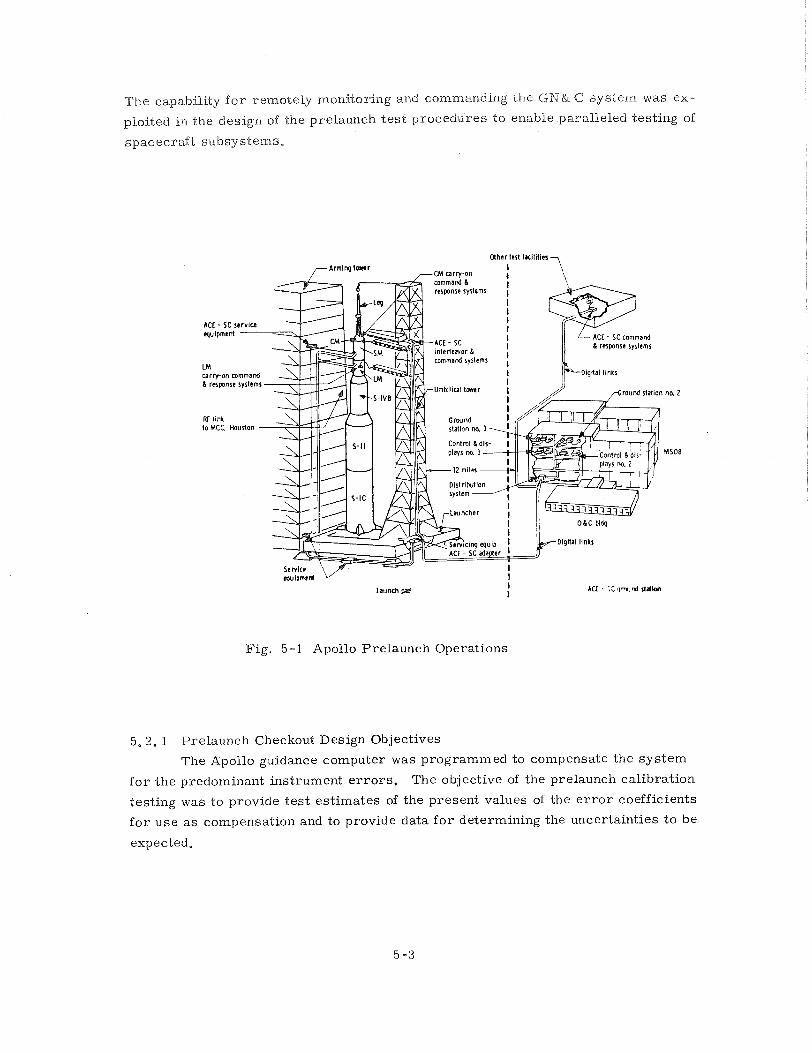
The capability f o r remotely monitoring and commanding the G N & 6 sys tem was ex-
ploited in the design of the prelaunch t e s t procedures to enable paralleled testing of
spaceera i t subsystems,
Uher tcrt laciliiln
-cM carrron I I
I bunch pad
I I
Acf - ;: q w m i %idion
Fig. 5 -1 Apollo Prelaunch Operations
5. 2. 1 Prelaunch Checkout Design Objectives
The Apollo guidance computer was programmed to compensate the sys tem
f o r the predominant instrument e r r o r s . The objective of the prelaunch calibration
test ing was to provide t e s t est imates of the present values of the e r r o r coefficients
f o r use a s compensation and to provide data f o r determining the uncertainties to be
expected.
The unique character is t ics of an iner t ia l sys tem utilizing a genera l purpose
digital computer with a remote control capability were exploited in the design of the
prelaunch calibration tes ts , The guidance sys tem calibration t e s t requirements
were designed to minimize the launch preparation t ime, The t e s t -method utilized
gravity t o eliminate the need f o r external references . The known amplitude of
gravity was used to calibrate the accelerometers , The gyro drif t calibration was
based on the detection of the vector rotation of gravity by the accelerometers , The
drif t information had t o be separated f rom accelerat ions caused by launch vehicle
accelerat ion resulting f r o m sway and f r o m noise a s a resul t of quantization in the
pulsed integrating pendulous accelerometer. The velocity quanta s i z e f o r the CM
was 5.85 c m / s and f o r the LM, 1 c m / s. The information was separated f rom the noise by a simplified optimum linear f i l ter , which included in i t s s t a t e vector,
es t imates of launch vehicle disturbances.
The measurements made on the launch pad were usually used a s reconfirma-
tions of the selected compensation values. The compensation pa ramete r s were
accelerometer bias and scale-factor e r r o r s f o r the th ree accelerometers , and gyro
b
of fifteen t e rms .
5 .2 -2 E r r o r Analysis f o r Prelaunch System Flight Worthiness Demonstration
The measurements made p r i o r t o launch were used a s indications of uncer-
tainties to be expected during a mission. The prelaunch sys tem performance data
had specified tolerances. In the c a s e s where the specified tolerances were exceeded,
the flight worthiness of the sys tem was evaluated on the basis of the probable m i s -
sion effect of the deviating parameter . As an example, shif ts of gyro drift parame-
t e r s beyond specified l imits during prelaunch t e s t s occurred on Apollo 3, 4, 5, 6.
Decisions about the flight worthiness of those sys tems were made by f i r s t classifying
the problem a s indicating possible catastrophic fai lure in flight o r one indicating
performance degradation. In c a s e s where reliability problems were suspected, the
Iner t ia l Measurements Unit was replaced (Apollo 6 ) . In the other cases , where
the t e s t data showed a performance degradation, determination of the mission effect
was required. This determination required the development of e r r o r analyses that
related variat ions of each of the measurable pa ramete r s to the mission.
Each mission in the Apollo program is unique. A separa te e r r o r analysis is
t o be performed f o r each. The mission performance requirements, based upon a
typical lunar landing, were defined ear ly in the Apollo program. Because of the
variety of missions and mission objectives, it was necessary to have a separa te
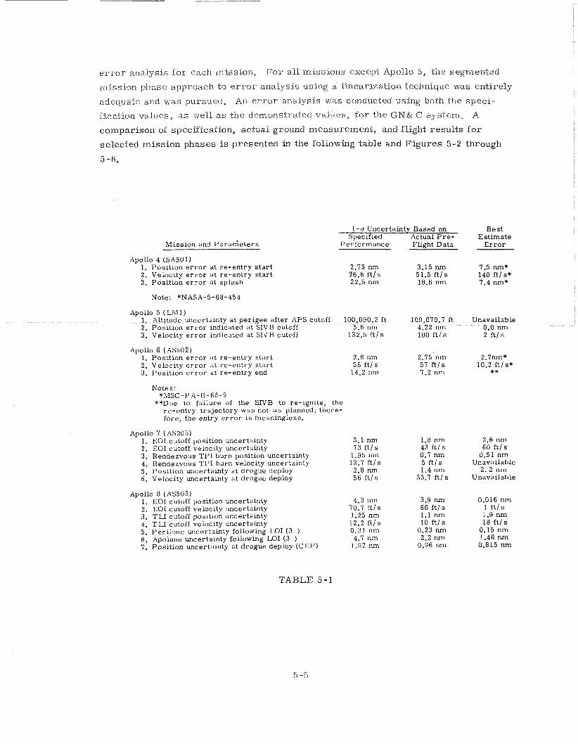
e r r o r analysis f o r each mission, F o r a l l miss ions except Apollo 5, the segmented
mission phase approach to e r r o r analysis using a linearization technique was entirely
adequate and was pursued, An e r r o r analysis was conducted using both the speci -
fication values, as well a s the demonstrated values, for the i ;N& C sys tem, A
cornparisoil of specification, actual ground measurement, and flight resul ts f o r
selected miss ion phases is presented in the following table and Figures 5-2 through
5 -6.
1-cr Uncertainty Based on Specified Actual P r e -
Miss ion and ~ a r a n i e t e r s Pe r f c rmance Flight Data
Apollo 4 (SA50 1) 1. Pos i t ion e r r o r a t r e - en t ry s t a r t 2. Velocity e r r o r at r e - en t ry s t a r t 3. Pos i t ion e r r o r at splash
Note: *NASA-5-68-454
Apollo 5 ( Lb11) 1. Altitude uncertamty a t per igee af ter APS cutoff 100,890.2 ft 109,079.7 ft 2. Pos i t ion e r r o r lndlcated at SIVB cutoff 5.6 nm 4.22 nm 3. Velocity e r r o r mdicsted at SIV'B cutoff 132.5 f t / s 100 f t / s
Apollo 6 (AS502) 1. Pos i t ion e r r o r at re-ent ry s t a r t 2. Velocity e r r o r a t r e - en t ry s t a r t 3. Pos i t ion e r r o r at r e - en t ry end
Notes: *MSC-PA-H-68-9
**Due to fa i lure of the SIVB to re-ignite, the r e - en t ry t r a j ec to ry was not a s planned; there- fore , the ent ry e r r o r i s meaningless.
Apollo 7 (AS205) 1. EOI cutoff position uncertainty 2. EOI cutoff velocity uncertainty 3. Rendezvous T P I burn position uncertainty 4. Rendezvous T P I burn velocity uncertainty 5. Pos i t ion uncertainty at drogue deploy 6. Velocity uncertainty a t drogue deploy
Apollo 8 (AS503) 1. EOI cutoff position uncertainty 2. EOI cutoff velocity uncertainty 3. T W cutoff position uncertainty 4. T W cutoff velocity uncertainty 5. Pe r i l une uncertainty following LO1 (3 ) 6. Apolune uncertainty following LO1 (3 ) 7. Pos i t ion uncertainty a t drogue deploy (CEP)
3.1 nm 73 f t l s
1.95 nm 13.7 f t / s 2.8 nm 56 f t / s
4.3 nm 70.7 f t / s 1.25 nm 12.2 f t l s 0.31 nm 4.7 nm
1.92 nm
3.9 nm 66 f t / s 1.1 nm 10 f t l s
0.23 nm 2.2 nm
0.96 n m
Best Es t ima te
E r r o r
7.5 nm* 140 f t / s * 7.4 nm*
Unavailable 0.0 nm 2 f t l s
2.7nm* 10.2 f t l s * * *
2.6 nm 60 f t / s
0.51 nm Unavailable
2 . 2 nm Unavailable
TABLE 5-1
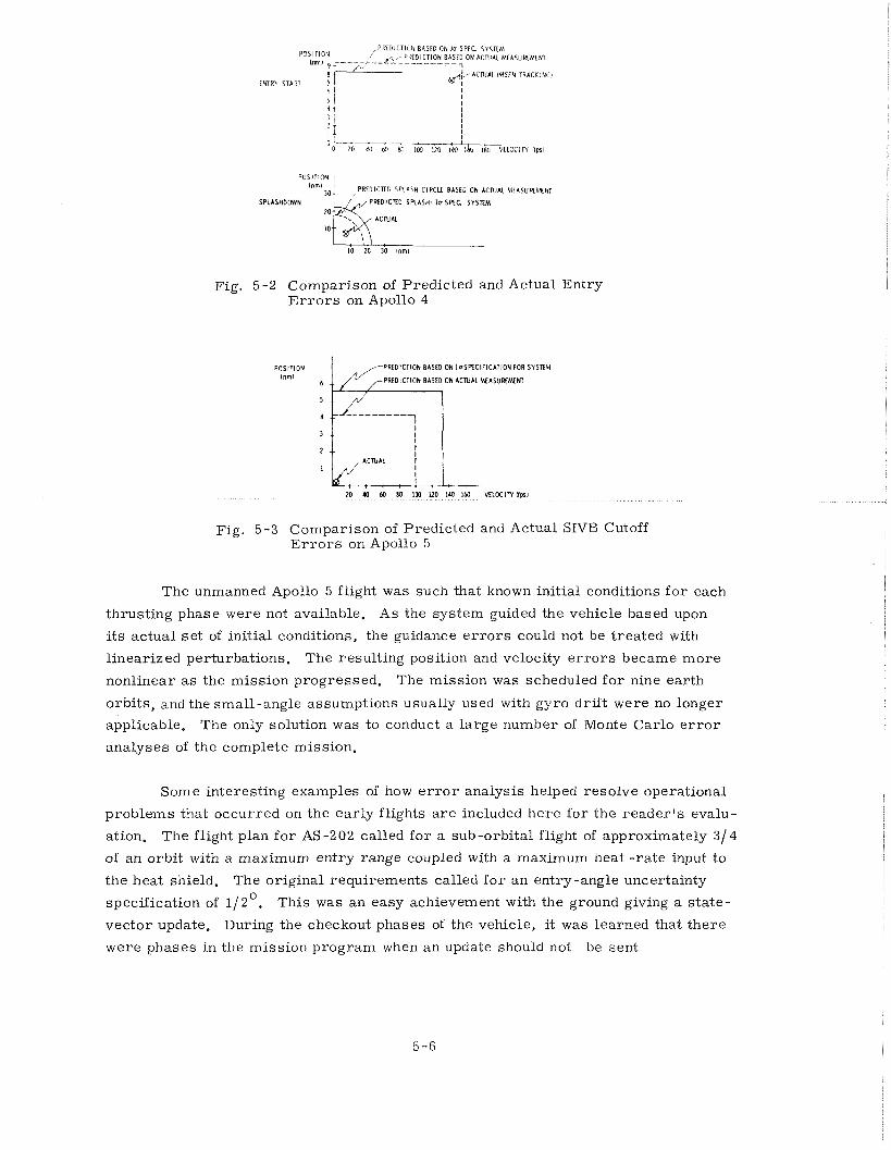
P O S l l l O N / P M D I C T I O N BASED ON% S P f C SYSTEM
(nm, k----+-- &-,: P R f ~ G T W ~ D ON A C N A L MEASURLhlENT A, 1
&ACNK M S F N r m ~ w ENTRY START
6 4 I 5 4 4 r I + 2 * 1 A
POSIT ION
PRLDtCTEC SPLASH C l R C u BASE" ON A C N M MEASUB~&NI
SPLASHDOWN TED;; S R A S H - I r S f f C S Y S E M
10
Fig. 5 -2 Comparison of Predicted and Actual Entry E r r o r s on Apollo 4
PREDICTION BAStD ON l o S R C I F I C A T I M ( FOR SYSTfM
6 ,,-PREDICTION BASED ON A C N A L MlASUKfMENl
Fig. 5-3 Comparison of Predicted and Actual SIVB Cutoff E r r o r s on Apollo 5
The unmanned Apollo 5 flight was such that known initial conditions f o r each
thrusting phase were not available. As the sys tem guided the vehicle based upon
its actual s e t of initial conditions, the guidance e r r o r s could not be treated with
l inearized perturbations. The resulting position and velocity e r r o r s became m o r e
nonlinear a s the miss ion progressed. The mission was scheduled f o r nine ear th
orbits , and the small-angle assumptions usually used with gyro dr i f t were no longer
applicable. The only solution was to conduct a large number of Monte Carlo e r r o r
analyses of the complete mission.
Some interest ing examples of how e r r o r analysis helped resolve operational
problems that occurred on the ear ly flights a r e included he re for the r e a d e r ' s evalu-
ation. The flight plan f o r AS-202 called f o r a sub-orbital flight of approximately 314
of an orbit with a maximum entry range coupled with a maximum heat - ra te input to
the heat shield. The original requirements called f o r an entry-angle uncertainty
specification of 112'. This was an easy achievement with the ground giving a s ta te-
vector update. During the checkout phases of the vehicle, it was learned that the re
were phases in the mission program when a n update should not be sent
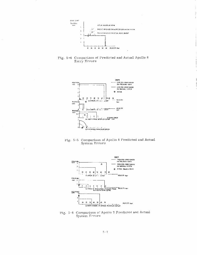
Fig. 5 -4 Comparison of Predicted and Actual Apollo 6 Entry E r r o r s
BE! ---- C X W C T R IRROR B A I l D ON P B U U W C H OATA
C X 4 C m ) [ R W R B A Y D ON W I N A L TYSlTU
-- *4 , , ,
m l ~ t u a o t r *I I L I C U ~ M V[LOCIW llpcl
*r ORBIT I R ~ R S LITR 1 0 1 CUTWF lnml
C I P AT DPOGUL PARACHIIT[ D f R O I
Fig. 5-5 Comparison of Apollo 8 Predicted and Actual System E r r o r s
= ---- P R i D I C m ) I R m R BASID
OH P B L I U K H OATA
PR(D1CIID 1RROR I A S t O
- - - - - - - - - OH M M l W l l S Y S R M
6~ rcrur~ 0" MS~NI
---c&4-4 I V CUROR IT L n I C U I ~ I % l M I N Np,l
Fig. 5-6 Comparison of Apollo 7 Predicted and Actual System E r r o r s
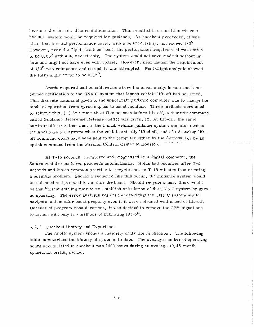
because of onboard software deficiencies. This resulted in a condition where a
backup sys tem would be required f o r guidance. As checkout proceeded, it was
c l e a r that iner t ia l performance could, with a 30 uncedainty, not exceed 1/30e
However, nea r the flight readiness t e s t , the performance requirement was stated
to be 0. 05' with a 30 uncertainty. The sys tem would not have made i t without up-
date and might not have even with update. However, n e a r launch the requirement
of 112' was reimposed and no update was attempted. Post-flight analysis showed
the entry angle e r r o r t o be 0. 12'.
Another operational consideration where the e r r o r analysis was used con-
cerned notification to the GN& C system that launch vehicle lift-off had occurred.
This d iscre te command given t o the spacecraf t guidance computer was to change the
mode of operation f r o m gyrocompass to boost monitor. T h r e e methods were used
to achieve this: ( 1 ) At a t ime about five seconds before lift-off, a d iscre te command
called Guidance Reference Release (GRR ) was given; ( 2 ) At lift -off, the same
hardwire d iscre te that went t o the launch vehicle guidance sys tem was also sent to
the Apollo GN& C system when the vehicle actually lifted off; and ( 3 ) A backup lift-
off command could have been sent to the compute
uplink command f r o m the Mission Control Center
At T-15 seconds, monitored and progressed by a digital computer, the
Saturn vehicle countdown proceeds automatically. Holds had occurred after T-5
seconds and it was common pract ice to recycle back to T-15 minutes thus creating
a possible problem. Should a sequence like th is occur, the guidance system would
be released and proceed to monitor the boost. Should recycle occur, there would
be insufficient settling t ime t o re-establish orientation of the GN & C system by gyro-
compassing, The e r r o r analysis resul ts indicated that the GN& C system would
navigate and monitor boost properly even i f it were released well ahead of lift-off,
Because of program considerations, it was decided to remove the GRR signal and
to launch with only two methods of indicating lift-off.
5.2.3 Checkout History and Experience
The Apollo system spends a majority of i t s life in checkout. The following
table summar izes the history of sys tems to date. The average number of operating
hours accumulated in checkout was 2460 hours during a n average 10.45-month
spacecraft testing period.
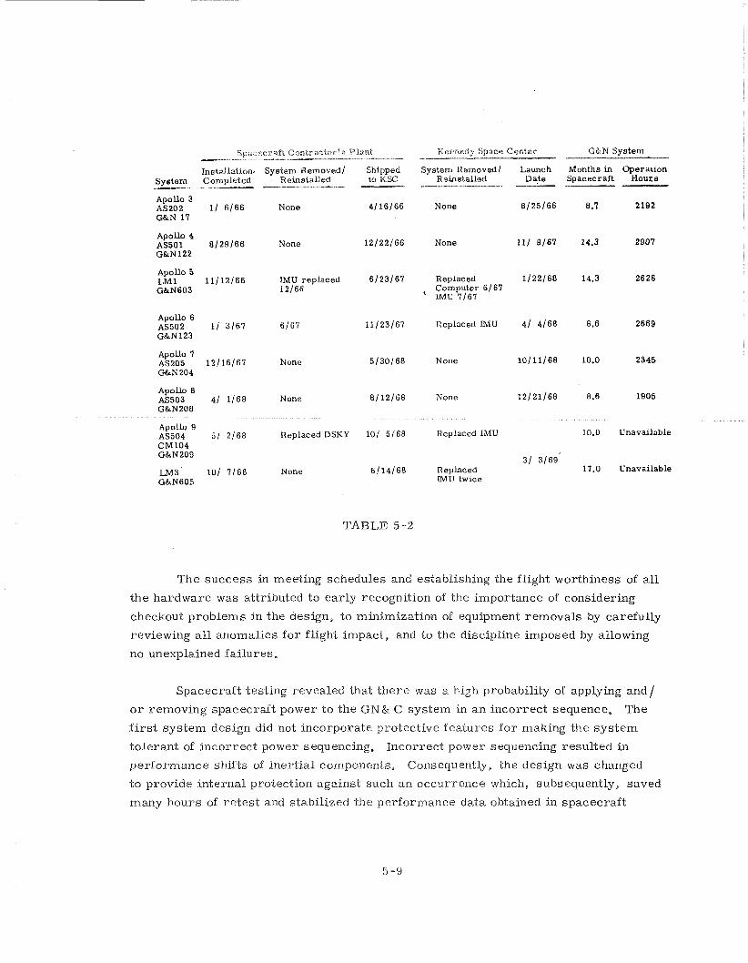
Spacecraft CantractorEs Plant Mentiedy Space Center G&N System ----- - hstal lat ton, System Removed/ Shapped System Removed/ Launch Months lh Operation
System Completed Remetalled to KSC Reinstalled Date Spacecraft Hours P P
Apollo 3 AS202 11 6 /66 None 4/16/66 None 8 /25/66 6.1 2192 GBrN 17
A p o h 4 AS501 8 /29/66 None 12/22/66 None 111 9/67 14.3 2907 G&N122
Apollo 5 LM1 11/12/66 M U replaced 6/23/67 Replaced 1 /22/68 14.3 2626 G&N603 12/66 , Computer 6/67
IMU 7/67
Apollo 6 AS502 11 3 /67 6/67 11/23/67 Replaced LMU 41 4/68 8.6 2669 G&N123
Apoll0 7 AS205 12/16/67 None 5130168 None 10/11/68 10.0 2345 G&N204
A p o h 8 M 5 0 3 4 / 1 / 6 8 None 8 /12/68 None 12/21/68 6.6 1905 G&N208
Apollo 9 AS504 5 / 2 / 6 8 ReplacedDSMY 101 5/68 Replaced IMU 10.0 Unavailable CM104 G&M209
31 3/69' LM3 101 7 /68 None 6!14/68 Replaced 17.0 Unavailable
G&N605 IMU twlce
TABLE 5-2
The success in meeting schedules and establishing the flight worthiness of a l l
the hardware was attributed to ear ly recognition of the importance of considering
checkout problems in the design, to minimization of equipment removals by carefully
reviewing a l l anomalies f o r flight impact, and to the discipline imposed by allowing
no unexplained fai lures.
Spacecraft testing revealed that the re was a high probability of applying and/
o r removing spacecraft power to the G N & C sys tem in a n incorrect sequence, The
f i r s t sys tem design did not incorporate protective fea tures f o r making the sys tem
tolerant of incorrect power sequencing. Incorrect power sequencing resulted in
performa.nce shifts of inert ial components. Consequently, the design was changed
t o provide internal protection against such an occurrence which, subsequently, saved
many hours of r e t es t and stabilized the performance data obtained in spacecraft
testing. Another example involved ground potential changes in docked t e s t configur-
ation. The possibility of r e v e r s e potential on the sys tem was not considered in the
initial design, When spacecraft t e s t s indicated that r e v e r s e voltages could exist a s
a resul t of grounding configurations, the G N & C system electronics design was
changed t o tolerate r e v e r s e voltages,
The prelaunch checkout had to guarantee that the equipment would operate
during the mission. When any discrepancy existed, positive action was taken to
eliminate possibility of f a i lu re in flight. An example of th i s was the fai lure of the
GN.& C sys tem to accept an entry mode change command once during checkout of
the AS-202 system, Even though the problem was never duplicated, the relays that
could have caused this single malfunction were replaced. Another example involved
the computer in the s a m e mission. While one of the computers was undergoing in-
spection a t the factory, it was discovered that one of the vibration isolation pads
was missing f rom the oscil lator module. Subsequent examination of other available
modules revealed that, on the basis of the sample examined, the re was about a 20%
chance that one of the vibration isolation pads was missing in the computer in the
The ear ly GN& C system operations were plagued by the occurrence of un- JI
explained restart"'. The concept of NO unexplained fa i lures required that each
r e s t a r t be explained. The computer r e s t a r t s were frequent ear ly in the program
but a s effort was applied to explain each one they were reduced to zero , Noise
susceptibility in t e s t connectors was discovered and corrected by a computer shor t -
ing plug, Software e r r o r s were discovered and corrected by new software. P r o -
cedural e r r o r s were discovered by means of ACE playbacks and laboratory verification,
The solution therefore involved hardware changes, software changes, procedural
changes and, above all, education and understanding on the pa r t of a l l G N & C sys tem
operation personnel. The successful operation of the hardware during the Apollo
flights w a s , pr imar i ly , the resul t of this careful disciplined engineering that ex-
amined a l l facets of the situation and left no a r e a uncorrected.
5, 3 - Flight Operations -- During a miss ion the GN& C operation was monitored by computers in the
Real T ime Control Center ( R T C C ) in Houston. The digital data generated by the
:x A r e s t a r t is an internal protective mechanism that enables the computer to recover f rom random program e r r o r s , operator e r r o r s , and f r o m environmental disturb - ances. Restar t at tempts t o prevent the loss of any operating functions.
onboard computer consisted of lists of two hundred 14-bit computer words t r a n s -
mitted once every two seconds, The contents of the lists were designed to provide
information relevant to the mission activity, The data were used to drive displays
on the g u i d a ~ c e officer 's corrsole and numerous other support consoles, The amount
of data f rom the guidance computer was limited by the word s ize and t ransmiss ion
ra te , The program design, however, allowed the program to select the quantities
to be transmitted and thus compensated f o r this deficiency, The data used f o r the
real - t ime displays were selected pr ior to the mission and were based onthe flight
control ler ' s experience and operational requirements. In r e a l time, the data format
was quite inflexible.
The control of the sys tem was accomplished in the same computer complex.
The data transmission paralleled the onboard keyboard-entry capability. The data
transmitted consisted for the most part of an update of the spacecraft position and
velocity, which was determined by ground tracking stations and converted into the
p roper format by the Houston RTCC. The controller had the capability of commanding
t h e spacecraft computer through an analogous keyboard with the s a m e codes a s those
of the astronauts.
Review of the data obtained f rom flight monitoring indicated that the ground
calibration enabled accurate e r r o r compensation. Review of the anomalies in flight
operations indicated that the re was a reasonable amount of t ime available during
the mission f o r troubleshooting and diagnosis of problems. The only cases that
could not be diagnosed in r e a l t ime involved inadequate real-t ime data.
5. 3, 1 Guidance System Monitoring During a Mission
The monitoring of the guidance sys tem performance during the mission con-
s is ted of comparing navigation data f rom other sources (ground tracking, Saturn V
guidance, LM backup for CM, CM backup f o r LM ), computing accelerometer out-
put with no input at zero gravity, and determination of the quality of the iner t ia l
r e fe rence by successive inflight optical realignments of the IMU. These successive
realignments were performed severa l hours apart s o that the rotations of the IMU
stable member required to realign it were mostly the result of gyro drift with the
fixed e r r o r s reduced inversely proportional to this t ime interval. There were also
operational techniques utilizing s t a r and planet horizons f o r checking the commanded
attitude pr ior to a velocity -change maneuver.
The onboard measurementof the available IMU performance parameters
could have been used to fur ther improve the performance, The compensation p a r a -
mete r s could be modified through the keyboard, ei ther onboard o r from the guidance
officer 's console in Eloustoil,
The guidance sys tem monitoring was designed to provide the flight controllers
with data upon which a prediction of the future operation of the system could be made.
The flight controllers had pre-programmed decision points that enabled the mission
to continue with a backup system in control, o r with a new mission plan if thei r data
indicated that the p r imary system might not perform adequately during the ensuing
cr i t ica l mission phase.
The data te lemetry f r o m the spacecraft was limited; hence, the ability to
predict future operation was difficult. The l imits s e t f o r the various parameters
were selected on the basis of the worst performance experienced during design
evaluation t es t s and prelaunch tes ts , excluding catastrophic failures.
Onboard measurements to date have indicated excellent performance. The
only onboard meas able fo r the unmanned missions ( Apollo 4, 5, 6 )
was accelerometer output at zero gravity ( a b ) . The manned missions also included
inert ial platform drift a t ze ro gravity (NBD ). The iner t ia l component data a r e pre-
sented in the following table and in Figure 5-7.
F igure 5-8 shows the monitoring of the IMU over a long period of continuous
operation. The data indicate that stability of inert ial operation was achieved in
the design. The entire component data history is presented in Figures 5-8 and 5-9.
5. 3. 2 Mission Diagnosis
The adequacy of a l l subsystems to continue into the next phase and t o complete
the mission was reviewed continuously by the flight controllers. It was important
therefore t o diagnose problems in r e a l t ime in support of the GO/ NO-GO decisions.
The flight experience showed that the re was adequate t ime available f o r problem
diagnosis and that the re was a capability for real-t ime troubleshooting. There were
two types of problems where real-t ime troubleshooting was of no value. These were
problems involving actual hardware fai lures and involving incompatibilities resulting
f rom inaccurate models of the spacecraft used in the control programs.
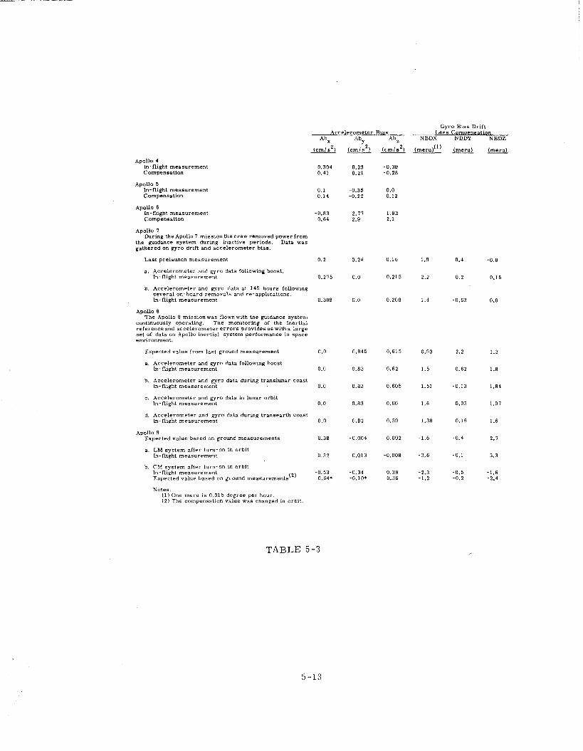
Accelerometer
Abx A b Y ( c m / s 2 ) ( c m / s 2 ) --
Bias
AbZ
( c m / s 2 )
Gyro B ~ a s D r ~ f t Less Compensation
NBDX NBDY NBDZ
(meru)"' (meru) (meru) - -- Apoll0 4
In-flight measurement Compensation
Apollo 5 In-flight measurement Compensation
Apollo 6 In-flight measurement compensation
Apollo 7 During the Apollo 7 mission the crew removed power from
the guidance system during inactive periods. Data was gathered on gyro drift and acce le romete r bias.
Last prelaunch measurement 0.2 0.24
a. Accelerometer and gyro data tollowlng boost. In-flight measurement 0.275 0.0
b. Accelerometer and gyro data at 145 hours following several on-board removals and re-applications, In-flight measurement 0.309 0.0
Apollo 8 The Apollo 8 missionwas flownwith the guidance system
continuously operatmg. The monitoring of the inertial reference and accelerometer e r r o r s provides us with a large set of data on Apollo inert ia l system performance in space environment.
Expected value f rom last ground measurement 0.0 0.845
a. Accelerometer and gyro data following boost In-flight measurement 0.0 0.83
b. Accelerometer and gyro data during t ranslunar coast In-flight measurement 0.0 0.83
c. Accelerometer and gyro data in lunar orbit In-flight measurement 0.0 0.83
d. Accelerometer and gyro data during t raneearth coast In-flight measurement 0.0 0.82
Apollo 9 Expected value based on ground measurements 0.38 -0.004
a. LM system after turn-on in orbit In-flight measurement
b. C?il system a f t e r turn-on in orbit In-flight measurement -0.53 -0.34 Expected value based on ground measurements(2 ' 0.648 -0.10'
Notes. (1) One meru is 0.015 degree per hour. 12) The compensation value was changed in orbit.
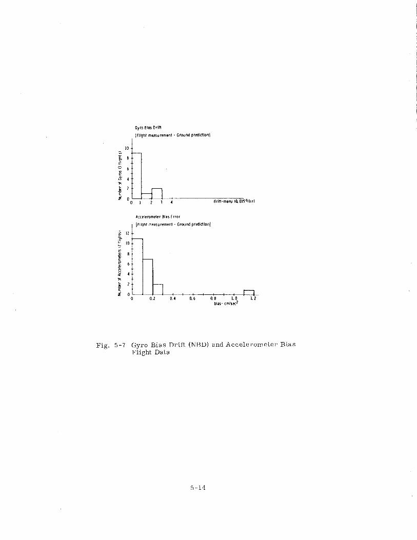
Gyro B l o Drlf l
Ifllght measuramtnt - Ground prcdlctlonl I
Accelcrnmdcr Blas t rror
Fig. 5-7 Gyro Bias Drift (NBD) and Accelerometer Bias Flight Data
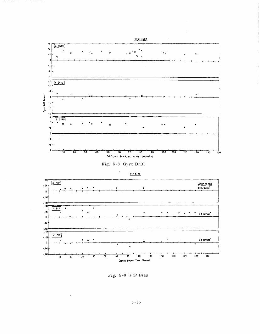
+3
+2
+1
0
-1
-2
-3
GROUND ELAPSED T I M E (HOURS)
Fig. 5-8 Gyro Drift
PIP B I A S
F i g . 5-9 PIP Bias
The following examples of problems involving the GN & C sys tem that have
been explained in r e a l t ime i l lustrate the capa.biiity that does exist:
( 1 ) APOLLO 4 (AS501 ), During the mission, i t w a s reported that a large
difference existed between the y indicated by the onboard computer and the y a s
compared f r o m r a d a r tracking data. y is the angle between the position vector and
the velocity vector. Real-t ime measurement of accelerometers indicated the GN& C
sys tem was operating properly. The difference was found to be a ground computa-
tion e r r o r . The guidance sys tem was allowed to continue in control of the mission.
( 2 ) APOLLO 6 (AS502 ). During the mission, a divergence was observed
between the attitude information supplied by the GN& C inert ial reference and the
backup body-mounted attitude gyros. The divergence was f i r s t attributed to GN& C
malfunction. Real-t ime review of prelaunch data f o r the backup sys tem indicated
that the drift r a t e s measured on the ground accounted f o r the divergence. The
GN& C sys tem remained in p r imary control f o r a successful mission.
( 3 ) APOLLO 7 During the mission, a procedure f o r using the landmark-
tracking navigation program f o r navigation sightings on the horizon was determined.
The procedure, however, did not work in the spacecraft. The computer was p ro -
grammed with a reasonable assumption that landmarks would be on the surface of
the earth. The at tempt to u s e the program f o r horizon sightings above the surface
of the ea r th ra the r than the landmarks resulted in the attempt to compute the square
root of a negative number. This resulted in a res tar t . The e r r o r in the procedure
was quickly determined by ground tests .
a. Computer Res ta r t - -The Apollo computer had a catalog of navigation
s t a r s identified by numbers. The astronaut, by keying in a numerical code, told
the computer the s t a r to be used. The r e s t a r t was the result of the astronaut not
selecting any s t a r when the computer requested a s t a r selection. The computer
interpreted the selection of "no" s t a r a s s t a r number 0; the catalog, however, s tar ted
with s t a r number 1. The resul t was a computer r e s t a r t resulting f rom accessing a
memory location address that did not "exist. I ' The r e s t a r t was diagnosed f rom rea l -
t ime displays.
b. Mark Button "Fai luref1- -The computer assimilated line-of -sight
data f r o m the optics only upon astronaut command, which consisted of an interrupt
caused by depressing the "mark" button on the navigator's control panel. The l ine-
of -sight information was used f o r rendezvous navigation a s well a s fo r inert ial

platform. realignment, To protect the rendezvous navigation information f rom being
modified by platform alignment sighting data, the computer programmers prevented
the processing of alignment "marks" during rendezvous navigation, The problem
occurred when the Astrona~rL terminated the rendezvous navigation program in a
fashion not expected by the programmers . This termination left the computer with
the information that no alignment "marks" were to be processed. The next attempt
at realignment failed a s a result of an apparent fai lure in the "mark" interface to
the computer. Ground troubleshooting uncovered the cause and a reselection and
proper termination of the navigation program eliminated the problem,
c. Accelerometer Bias Change--The accelerometers in the Apollo
inert ial measurement unit were Pulsed Integrating Pendulous Accelerometers,
PIPAs. The accelerometer used a pendulous m a s s a s a torque summing element,
The accelerometer bias (output with no input) resulted f rom the residual torques
in the instrument. During a mission, a t zero gravity, the accelerometer was cal -
ibrated by monitoring i t s output, During Apollo 7 , the flight controllers noticed
that the expected low output at ze ro gravity decreased to zero. This was interpreted
a s a possible hardware fa i lure and an inflight tes t was conducted to determine if
the instrument was operating properly. The t es t consisted of a maneuver to thrus t
along both directions of the accelerometer input axes. The results showed that the
instrument was operating properly. The cause f o r the lack of any output was simply
the PIPA reaching an operating region in f ree - fa l l where the torque generated by
electronic nonlinearities was equal and opposite to the residual electromagnetic
torques, and this yielded zero bias.
( 4 ) APOLLO 8 ( Prelaunch Alignment during the Transear th Coast ) The
commanding of the Apollo guidance computer consisted mainly in selecting numeri-
cally coded programs and loading the desired number a t the t ime the computer r e -
quested the information. The loaded information was redisplayed fo r confirmation
by the Astronautprior to being acted upon by the computer. The astronaut confirmed
that he indeed wanted the displayed program to be executed by depressing a key on
the keyboard.
The prelaunch alignment program was coded 01. It was inadvertently se lec -
ted by the astronaut during the t ransear th coast. The problem that a rose resulted
mainly f r o m the fact that the erasable portion of the computer memory was t ime-
shared. The effect on the contents of the erasable memory of start ing program 01
a t that t ime was unknown. The problem was quickly dealt with by the crew and the
contents of the memory verified by the ground to be correct .
The problems invo2viiig the G N & C sys tem in the Apollo flights were minor.
They provided an object lesson of the types of problems to be expected in a l a rge
program with many opportunities f o r e r r o r in design and operation,
The operational problems can be categorized to indicate where the operational
s y s t e m is most susceptible to e r r o r . The types of problems to date have been the
following:
a . Ground E r r o r s - - T h e problems that can be categorized a s ground
e r r o r s included only those that a r o s e in r e a l time. These types of e r r o r s can be
dealt with by rea l - t ime troubleshooting. Some examples have been already described.
b, Operator E r r o r s - -Although the interface between the astronauts
and the guidance sys tem had been carefully engineered during manned missions,
the deficiencies of the sys tem showed up very clearly in the examples described.
The selected major rea l - t ime problems, categorized below a s opera tor e r r o r s ,
c lear ly reflect difficulties in the design of the interactive computer programs and
the i r use under mission conditions. These types of problems a lso can be easi ly
diagnosed and corrected.
c , Misinterpretation of Design Data--The attitude and thrus t -vector
control sys tems incorporated in the Apollo guidance computer memory depend on
accura te models of the spacecraft. Problems a r i s e when the spacecraft responds
to commands different f rom those that the computer program expects, The result
can be a performance degradation resulting f rom either a logical e r r o r o r incorrect
information in the computer; both have occurred:
AS202 L /D Problem--The otherwise successful suborbital mission
missed the target by 200 miles. The major cause was the lift-to-drag rat io, L/D, of
of an expected 0. 35 ve r sus a n actual 0.25 with the resul t that the vehicle had insuf - ficient lift t o attain the targeted range.
APOLLO 6 DPS Engine Shutdown--The control program f o r guidance
during L M descent propulsion sys tem engine operation monitored the thrus t build-up
a f t e r the engine had been commanded to f i r e . If the thrust build-up had not occurred,
the program was designed to tu rn off the engine and generate an a larm. During the
flight, the engine thrus t build-up, fo r the f i r s t descent engine burn, did not occur
a t the r a t e expected by the program, and the computer turned off the engine. The
p rogram was designed s o that appropriate rea l - t ime commands could have res tar ted
the control program but, because of ground tracking considerations, the mission was
flown with backup procedures.
d. Mjsinterpretatior* of Flight Telemetry Data- -The spacecraft te le - rnetry data a r e processed by a computer complex a t Houston to provide rea l - t ime
displays f o r the flight controllers, The limitations of that sys tem require that some
data not be displayed, The display, therefore , does not give an exact picture of
the spacecraft s tatus, The p r ime example of how the selected displays caused m i s -
interpretation occurred on Apollo 8.
The flight plan of Apollo 8 called f o r the power to the GN& C optical
subsystem to be left ON throughout the mission. The telemetry fo r the s t a t e of that
power was not selected f o r rea l - t ime display, The computer monitored the sextant
articulating line-of -sight angles, and this information was transmitted a s pa r t of
the computer down-telemetry, Several t imes during the mission, the computer data
indicated that the "trunnion" angle, one of the two data encoded optics sys tem angles,
changed f r o m the expected 0' to an unexpected 45'. This change was unexplainable
f rom the available data. The sys tem operation, however, indicated that by recycl-
ing normal optics operating procedures the sys tem was not affected. The decision
to continue to the moon was based on that fact . Severa l fa i lure models were invented
during the miss ion to explain the problem. Later , during astronaut debriefing, it became apparent that the problem was attributed t o the switching O F F of optics
power. With power removed, the change in angle was t o be expected each t ime the
power was reapplied. A sea rch through the data, which was not processed in r e a l
t ime, confirmed that explanation.
e. New Phenomena- -To date, the re have been very few s u r p r i s e s in
the flight operations of the Apollo GN& C system. The following observations will
have an effect on future GN& C design:
Visibility--Navigation in cislunar space and alignment of the i n e r -
t i a l platform depend on the astronaut 's identification of navigation s t a r s . The debr is
generated by the spacecraf t can appear in the optics a s s t a r s to make t r u e s t a r
identification difficult. The Apollo missions, therefore, have made extensive use
of the computer-inert ial measurement unit combination to direct the optical line-of -
sight to aid s t a r identification.
Per igee Torquing--The s i ze of the Apollo spacecraft resulted in
considerable attitude changes in ear th orbit a s a resul t of atmospheric drag at pe r i -
gee, This could be costly in fuel f o r large space stations,
f , Hardware Prob lems- -There were very few G & N related hardware
problems in the Apollo missions, The careful ground t e s t and review of t e s t resul ts
were the main reasons f o r the inflight success , Hardware problems that occurred
in flight resulted in use of backup systems.
The major problem that involved the G & N was the Apollo 6 ground update
procedure. The unmanned Apollo miss ions were dependent on ground tracking navi-
gation data to a much g rea te r extent than the manned missions. Several navigation
updates were planned f o r Apollo 6. The navigation data o r o ther remote commands
to the computer were transmitted in a triple-redundant code, KKK, The computer
would not accept data that did not conform to this code.
During the Apollo 6 mission, severa l at tempts to send navigation updates
were rejected by the computer, The most likely cause f o r rejecting the data was
electromagnetic interference. Review of the interface did indicate a possible prob-
l em resulting f r o m ground command lines left disconnected a t launch and untermin-
ated. These wires were acting a s the probable antenna f o r picking up the noise,
The source of the in ter ference was l a t e r determined to be a n ion pump a s -
sociated with the fuel cells. The ion pump in the Apollo 7 spacecraft generated the
s a m e problem during a ground t e s t in the altitude chamber. The Apollo 6 ion pump
had not been ground tested in the altitude chamber. Wiring changes were a lso made
in subsequent spacecraft t o eliminate the possible noise pickup in the ground com-
mand l ines.
5, 4 Conclusions
( 1 ) Flight performance indicated that the sys tem e r r o r mode contained in
the specification was a good representation of the actual sys tem e r r o r s during a
mission. There was excellent agreement between the ground and the free-fal l inertial
p a r a m e t e r measurements.
( 2 ) The quality and reliability was designed and built into the equipment.
With a well planned and well designed prelaunch checkout, inflight hardware p ro -
blems were minimized.
( 3 ) Operational experience showed that automatic prelaunch checkout of
space guidance, navigation, and control sys tems proved to be the best approach.
( 4 ) The mission techniques were designed ai'ter "Lie hardware was built,
Therefore, the hardware had to be flexible to accommodate different mission appli-
cations.
( 5 ) The complexity of the G N & C system, a s well a s of the total spacecraft ,
dictated that emphasis be placed on simulation f o r verification and training.
( 6 ) There was reasonable t ime available f o r inflight problem diagnosis,
and the re existed an ability fo r troubleshooting and diagnosis both in flight and on
the ground.
( 7 ) Any problem found must be related ( b y the use of s t r ic t build control )
t o al l possible sys tems, and the effects evaluated based upon requirements.
( 8 ) The concept of no unexplained fa i lure was additional assurance of
achieving success during the complex Apollo effort.
Section V I
The Guidance and Navigation ( G & N ) design and manufacturing effort was
managed by the Guidance and Control Division of the NASA Manned Spacecraft Center,
and MIT was assigned p r ime responsibility fo r a l l phases of the G & N design. MIT's
responsibility included determination of the G & N configuration, design concepts,
performance manufacturing methods and techniques, reliability and quality assurance,
operation performance, computer programming, crew procedures, ground support
equipment, configuration control, negotiations with the spacecraft contractors f o r
G & N integration with the spacecraft , and technical direction to the G & N manufac-
turing contractors.
Soon af ter the design phase was initiated, MSC let out contracts t o par t ic i -
pating contractors fo r the manufacture of the G & N under MIT supervision.
Raytheon Corporation was selected to build the computer group, Kollsman Instrument
Corporation the optical units, and AC Electronics Division ( fo rmer ly called AC
Spark Plug Division of General Motors Corporation) was selected t o build the r e -
mainder of the G & N system including the inert ial subsystem, Displays and Controls,
PSA, CDU, interconnecting ha rnesses , s ignal conditioning equipment, navigation
base, eyepiece, and s torage unit, AC Electronics Corporation was a lso given the
task to assemble and t e s t the complete G & N System. Separate contracts were
awarded t o AC Electronics Corporation and Sperry Gyroscope Corporation f o r the
manufacture of the IRIGs and PIPAs.
Engineering personnel f rom these participating contractors were brought in
a s temporary resident engineers to a s s i s t in the design. This gave the manufacturing
organizations the opportunity to become intimately famil iar with the design a s it
developed, and t o develop an awareness of the philosophies, design concepts, t r ade -
offs and compromises that a r e an integral par t of any development effort, The
contractors in genera l sent well qualified senior personnel to a s s i s t in the task.
The successful design of the Apollo G & N system was dramatically demon-
s t ra ted by the spectacular G & N performance evidenced throughout the Apollo flights.
Most design changes evolved f rom schedule constraints that demanded ear ly
re leases of design Lo production. The schedule did not permit the luxury of testing
breadboards and prototype models in the expected environments p r io r to design r e -
lease. Much of the tes t ing occurred af ter production was too f a r along to make
indicated design changes without prohibitive expense. F o r th is reason, changes
were not made unless i t could be demonstrated that the existing design simply would
not suffice fo r the intended task. Designs were re leased f o r production before in ter -
face constraints were formalized with the spacecraft contractors, a situation that
made Interface Control Document ( ICD ) negotiations troublesome, resulting in
additional design changes and compromises, and in s o m e instances, leading to l e s s
than optimum spacecraft configuration.
NASA, evoking the Apollo Configuration Management Manual NPC 500 - 1,
imposed s t r i c t configuration control requirements on a l l Apollo contractors. Im-
plementation of these requirements required a major documentation effort. Ear ly
designs were released with c l a s s B documentation and were not subject t o fo rmal
configuration controls but were used mainly f o r information, sys tem integration,
and production planning, Design changes were readily made and documented a s
s imple revisions to the drawings and specifications. With the re lease to manufac-
turing, the documentation was formalized a s c l ass A, and subject to a l l rigid con-
figuration control and configuration identification restr ict ions.
Correspondingly, every change resulting in a piece p a r t t h a t w a s n o t
throughly interchangeable in forward o r backward production required a new par t
number, and additionally, pa r t numbers were required f o r a l l related higher a s -
semblies. This procedure led to a major documentation effort on the part of the
design groups who maintained the i r own drawings. Moreover, complaints were
registered that the design effort was being diluted by documentation.
The many changes that were made was a consequence of designs being r e -
leased p r i o r to adequate test ing evaluation. The complaints notwithstanding,
configuration documentation difficulties did have a stabilizing influence in the design
a reas . In any case , changes that were not mandatory simply were not made unless
a significant benefit in cost , schedule and reliability was evident. The ultimate
configuration control was effected through f o r m a l design review and change control
boards.
As previously indicated, iriterfaee agreements with the spacecraft contrac - t o r s were troublesome and a t t imes difficult, NASA had labored with the contrac-
t o r s to establish formal interface negotiating procedures and had assisted in defining
the interface a reas , Preliminary irJorniation was exchanged and preliminary in ter-
face control documents were prepared. NASA then left it to the contractors to work
out interface details and to document the agreed upon interfaces in approved ICDs.
Dialogue was maintained between the contractor and MIT, and design information
was being exchanged, but no r e a l progress in defining the interfaces was being made
at that time. Each G& N and spacecraft contractor had a constricted schedule to
mee t and was not willing to invalidate that schedule t o accommodate another associa-
t e ' s design.
During the spring of 1965, very few ICDs were approved. It was becoming
increasingly evident that a number of interfaces were incompatible. In the s u m m e r
of 1965, NASA assembled a task f o r c e to resolve a l l of the interface differences.
Within the span of a few weeks, a l l interfaces were negotiated and ICDs signed.
Where design changes were indicated, implementation directives were received
f rom NASA. Where design data were insufficient, supplements were issued.
Henceforth, NASA closely scrutinized a l l ICDs. Changes, a s required,
were promptly negotiated, thus keeping cost and schedule impacts to a minimum.
The lesson to be learned f rom the foregoing experience is that contractors, left
to thei r own devices, will invariably procrastinate and belabor details in defense of
the i r own designs. What is needed is an objective arbi ter to p r o v i d e a continuing
impetus to the program by resolving a l l design contentions.
The ICDs that caused the most trouble for the ISS were the pr ime dc power
ICDs, the thermal ICDs and the ICDs that define the mechanical attachment of the
G & N equipment t o the vehicles.
The G & N electronics, which was designed to operate from 28 Volt - + 570
spacecraft-supplied power source, manifested problems when some ci rcui ts operated
above the prescribed level and were thermally overstressed. Below that level, the
c i rcui ts would be operating outside of their dynamic range, and performance would
be accordingly degraded. After the design re lease t o the manufacturer, both space-
craf t contractors revealed that they could not meet the 28 V - + 5%. The problem
was finally resolved by NASA when the spacecraft power sys tems were modified t o
maintain the voltage to 28. 5 V + - 1470. Some G & N circuitry was a lso redesigned t o
accommodate these levels. Problems with the thermal ICDs were caused by the
fac t that the rmal conductance between the electronic packages was l e s s than originally
designed for. This predicament necessitated relocating s o m e of the modules in the
command module PSA to reduce local hot spots. Module relocation, in turn , af -
fected the PSA bolt mounting pattern; and a s a result , the spacecraft coldplate r e -
quired redesigning.
In summation, the Apollo experience has shown that MIT design capabilities
in collaboration with the participating contractor manufacturing function, were a
most effective means of developing the Guidance and Navigation System. Unhampered
by the myriad detai ls associated with production tooling and logistics, MIT was able
t o concentrate i t s r e sources of talent to produce a relatively smal l , effective design
team. As such, MIT, unlike l a r g e r organizations, was not plagued by internal com - munication problems and design control bureaucracies. Moreover, because of i t s
unique nature, NIIT was in a position t o monitor the activities of the participating
contractors without being influenced by profit motives, thus virtually insuring a
quality end item.
DISTRIBUTION LIST
Internal:
J. Alekshun
R. Booth
R. Cooper
J. Carrigan
W. Denhard
A. Freeman
J. Gilmore
E . Hall
R. Harlow
D. Hoag
F. Houston
P. Jopling
A. Laats
L, Larson
J. Lebo
R, Lones
R. McKern
G. Ogletree
R. Ragan
N. Sears
W. Stameris
R. Weatherbee
R. Woodbury
Apollo Library (40)
Tech Doc Center (10)
External:
NASA Electronics Research Center Cambridge, Mass.
1 Repro + 50 Copies
Attn: M. L. Bystock