Embed Size (px)
Citation preview
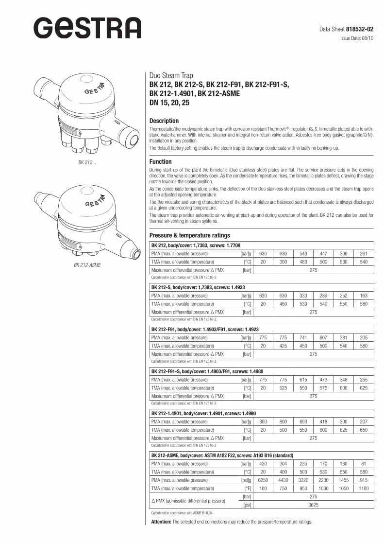
Duo Steam Trap BK 212, BK 212-S, BK 212-F91, BK 212-F91-S, BK 212-1.4901, BK 212-ASMEDN 15, 20, 25
DescriptionThermostatic/thermodynamic steam trap with corrosion resistant Thermovit® regulator (S. S. bimetallic plates) able to withstand waterhammer. With internal strainer and integral nonreturn valve action. Asbestosfree body gasket (graphite/CrNi). Installation in any position.The default factory setting enables the steam trap to discharge condensate with virtually no bankingup.
FunctionDuring startup of the plant the bimetallic (Duo stainless steel) plates are flat. The service pressure acts in the opening direction, the valve is completely open. As the condensate temperature rises, the bimetallic plates deflect, drawing the stage nozzle towards the closed position.As the condensate temperature sinks, the deflection of the Duo stainless steel plates decreases and the steam trap opens at the adjusted opening temperature.The thermostatic and spring characteristics of the stack of plates are balanced such that condensate is always discharged at a given undercooling temperature.The steam trap provides automatic airventing at startup and during operation of the plant. BK 212 can also be used for thermal airventing in steam systems.
Pressure & temperature ratings
BK 212, body/cover: 1,7383, screws: 1.7709
PMA (max. allowable pressure) [bar]g 630 630 543 447 306 261
TMA (max. allowable temperature) [°C] 20 300 480 500 530 540
Maxiumum differential pressure Δ PMX [bar] 275Calculated in accordance with DIN EN 125162
BK 212-S, body/cover: 1,7383, screws: 1.4923
PMA (max. allowable pressure) [bar]g 630 630 333 289 252 163
TMA (max. allowable temperature) [°C] 20 450 530 540 550 580
Maxiumum differential pressure Δ PMX [bar] 275Calculated in accordance with DIN EN 125162
BK 212-F91, body/cover: 1.4903/F91, screws: 1.4923
PMA (max. allowable pressure) [bar]g 775 775 741 607 381 205
TMA (max. allowable temperature) [°C] 20 425 450 500 540 580
Maxiumum differential pressure Δ PMX [bar] 275Calculated in accordance with DIN EN 125162
BK 212-F91-S, body/cover: 1.4903/F91, screws: 1.4980
PMA (max. allowable pressure) [bar]g 775 775 615 473 348 255
TMA (max. allowable temperature) [°C] 20 525 550 575 600 625
Maxiumum differential pressure Δ PMX [bar] 275Calculated in accordance with DIN EN 125162
BK 212-1.4901, body/cover: 1.4901, screws: 1.4980
PMA (max. allowable pressure) [bar]g 800 800 693 418 300 207
TMA (max. allowable temperature) [°C] 20 500 550 600 625 650
Maxiumum differential pressure Δ PMX [bar] 275Calculated in accordance with DIN EN 125162
BK 212-ASME, body/cover: ASTM A182 F22, screws: A193 B16 (standard)
PMA (max. allowable pressure) [bar]g 430 304 235 170 130 81
TMA (max. allowable temperature) [°C] 20 400 500 530 550 580
PMA (max. allowable pressure) [psi]g 6250 4430 3220 2230 1455 915
TMA (max. allowable temperature) [°F] 100 750 950 1000 1050 1100
Δ PMX (admissible differential pressure)[bar] 275
[psi] 3625
Calculated in accordance with ASME B16.34
Attention: The selected end connections may reduce the pressure/temperature ratings.
BK 212 ..
BK 212-ASME
Data Sheet 818532-02Issue Date: 08/10
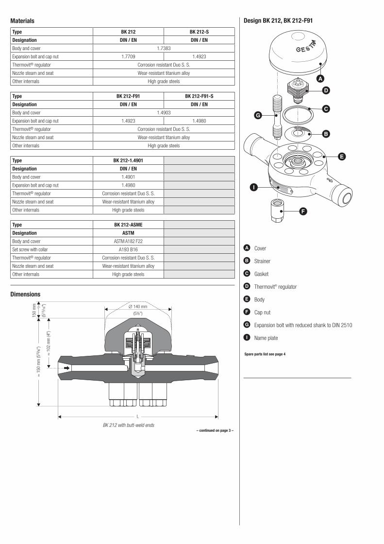
Materials
Type BK 212 BK 212-S
Designation DIN / EN DIN / EN
Body and cover 1.7383
Expansion bolt and cap nut 1.7709 1.4923
Thermovit® regulator Corrosion resistant Duo S. S.
Nozzle steam and seat Wearresistant titanium alloy
Other internals High grade steels
Type BK 212-F91 BK 212-F91-S
Designation DIN / EN DIN / EN
Body and cover 1.4903
Expansion bolt and cap nut 1.4923 1.4980
Thermovit® regulator Corrosion resistant Duo S. S.
Nozzle steam and seat Wearresistant titanium alloy
Other internals High grade steels
Type BK 212-1.4901
Designation DIN / EN
Body and cover 1.4901
Expansion bolt and cap nut 1.4980
Thermovit® regulator Corrosion resistant Duo S. S.
Nozzle steam and seat Wearresistant titanium alloy
Other internals High grade steels
Type BK 212-ASME
Designation ASTM
Body and cover ASTM A182 F22
Set screw with collar A193 B16
Thermovit® regulator Corrosion resistant Duo S. S.
Nozzle steam and seat Wearresistant titanium alloy
Other internals High grade steels
L
∅ 140 mm
(5½")150
mm
(515
/16"
)≈
150
mm
(515
/16")
≈ 1
02 m
m (4
")
Dimensions
BK 212 with butt-weld ends– continued on page 3 –
Design BK 212, BK 212-F91
A
B
C
D
E
G
F
I
A Cover
B Strainer
C Gasket
D Thermovit® regulator
E Body
F Cap nut
G Expansion bolt with reduced shank to DIN 2510
I Name plate
Spare parts list see page 4
L
∅ 140 mm
(5½")70 m
m
(2¾
")≈
150
mm
(515
/16")
≈ 1
02 m
m (4
")
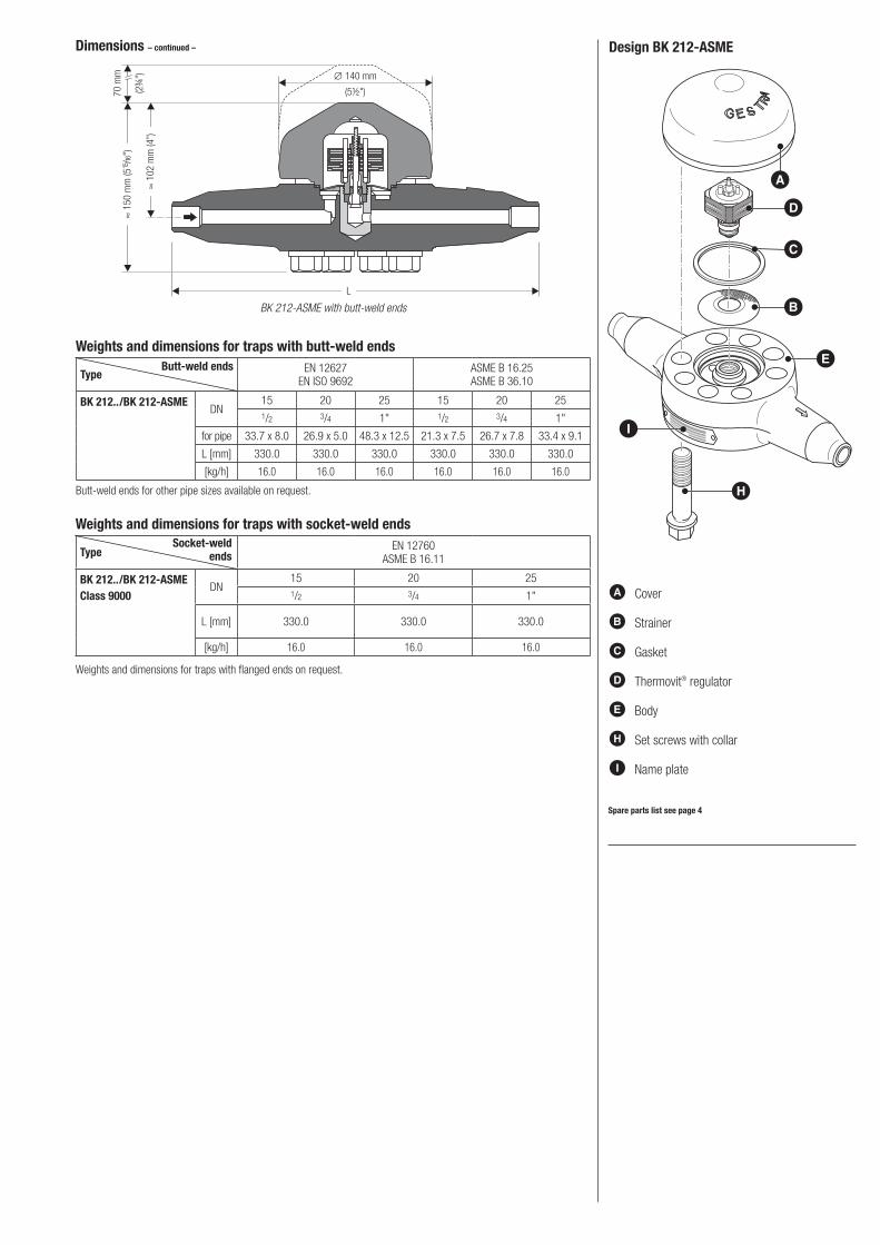
Dimensions – continued –
BK 212-ASME with butt-weld ends
Design BK 212-ASME
A
B
C
D
E
H
I
A Cover
B Strainer
C Gasket
D Thermovit® regulator
E Body
H Set screws with collar
I Name plate
Spare parts list see page 4
Weights and dimensions for traps with socket-weld ends
Type EN 12760ASME B 16.11
BK 212../BK 212-ASMEClass 9000
DN15 20 251/2 3/4 1"
L [mm] 330.0 330.0 330.0
[kg/h] 16.0 16.0 16.0
Weights and dimensions for traps with butt-weld ends
Type EN 12627EN ISO 9692
ASME B 16.25 ASME B 36.10
BK 212../BK 212-ASMEDN
15 20 25 15 20 251/2 3/4 1" 1/2 3/4 1"
for pipe 33.7 x 8.0 26.9 x 5.0 48.3 x 12.5 21.3 x 7.5 26.7 x 7.8 33.4 x 9.1
L [mm] 330.0 330.0 330.0 330.0 330.0 330.0
[kg/h] 16.0 16.0 16.0 16.0 16.0 16.0
Buttweld ends for other pipe sizes available on request.
Weights and dimensions for traps with flanged ends on request.
Butt-weld ends
Socket-weld ends
Duo Steam Trap BK 212, BK 212-S, BK 212-F91, BK 212-F91-S, BK 212-1.4901, BK 212-ASMEDN 15, 20, 25
81853202/082010cm (80875002) · GESTRA AG · Bremen · Printed in Germany
Supply in accordance with our general terms of business.
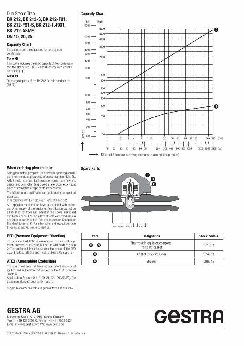
Capacity ChartThe chart shows the capacities for hot and cold condensate.
Curve 1This curve indicates the max. capacity of hot condensate that the steam trap BK 212 can discharge with virtually no banking up.
Curve 2Discharge capacity of the BK 212 for cold condensate (20 °C).
Capa
city
Differential pressure (assuming discharge to atmospheric pressure)
DWhen ordering please state:Sizing parameters (temperature, pressure), operating parameters (temperature, pressure), reference standard (DIN, EN, ASME etc.), materials, backpressure, condensate flowrate, design, end connection (e. g. pipe diameter), connection size, place of installation or type of steam consumer.The following test certificates can be issued on request, at extra cost:In accordance with EN 102042.1, 2.2, 3.1 and 3.2.All inspection requirements have to be stated with the order. After supply of the equipment certification cannot be established. Charges and extent of the above mentioned certificates as well as the different tests confirmed therein are listed in our price list “Test and Inspection Charges for Standard Equipment”. For other tests and inspections than those listed above, please consult us.
PED (Pressure Equipment Directive)The equipment fulfills the requirements of the Pressure Equipment Directive PED 97/23/EC. For use with fluids of group 2. The equipment is excluded from the scope of the PED according to Article 3.3 and must not bear a CE marking.
ATEX (Atmosphère Explosible)The equipment does not have ist own potential source of ignition and is therefore not subject to the ATEX Directive 94/9/EC. Applicable in Ex zones 0, 1, 2, 20, 21, 22 (1999/92/EC). The equipment does not bear an Ex marking.
Capacity Chart
Item Designation Stock code #
C D Thermovit® regulator, complete, including gasket 371862
C Gasket (graphite/CrNi) 374009
B Strainer 096345
BC
Spare Parts
GESTRA AG Münchener Straße 77, 28215 Bremen, GermanyTelefon +49 421 35030, Telefax +49 421 3503393Email [email protected], Web www.gestra.de
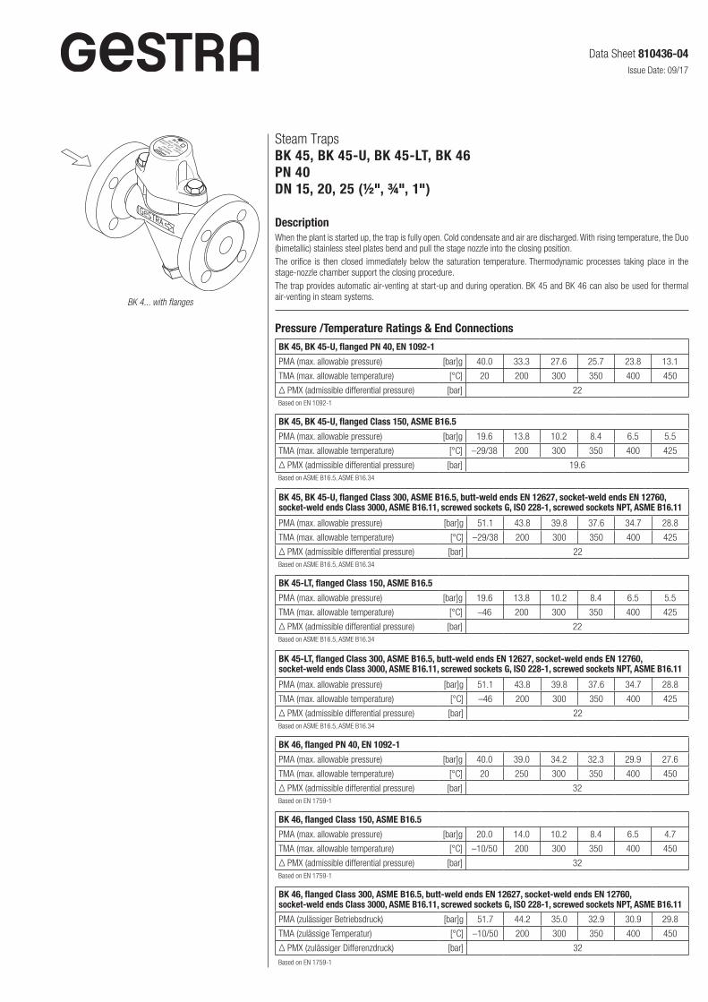
Steam TrapsBK 45, BK 45-U, BK 45-LT, BK 46PN 40DN 15, 20, 25 (½", ¾", 1")
DescriptionWhen the plant is started up, the trap is fully open. Cold condensate and air are discharged. With rising temperature, the Duo (bimetallic) stainless steel plates bend and pull the stage nozzle into the closing position. The orifice is then closed immediately below the saturation temperature. Thermodynamic processes taking place in the stage-nozzle chamber support the closing procedure.The trap provides automatic air-venting at start-up and during operation. BK 45 and BK 46 can also be used for thermal air-venting in steam systems.BK 4... with flanges
Data Sheet 810436-04Issue Date: 09/17
Pressure /Temperature Ratings & End Connections
BK 45, BK 45-U, flanged PN 40, EN 1092-1
PMA (max. allowable pressure) [bar]g 40.0 33.3 27.6 25.7 23.8 13.1
TMA (max. allowable temperature) [°C] 20 200 300 350 400 450
Δ PMX (admissible differential pressure) [bar] 22Based on EN 1092-1
BK 45, BK 45-U, flanged Class 150, ASME B16.5
PMA (max. allowable pressure) [bar]g 19.6 13.8 10.2 8.4 6.5 5.5
TMA (max. allowable temperature) [°C] –29/38 200 300 350 400 425
Δ PMX (admissible differential pressure) [bar] 19.6Based on ASME B16.5, ASME B16.34
BK 45, BK 45-U, flanged Class 300, ASME B16.5, butt-weld ends EN 12627, socket-weld ends EN 12760, socket-weld ends Class 3000, ASME B16.11, screwed sockets G, ISO 228-1, screwed sockets NPT, ASME B16.11
PMA (max. allowable pressure) [bar]g 51.1 43.8 39.8 37.6 34.7 28.8
TMA (max. allowable temperature) [°C] –29/38 200 300 350 400 425
Δ PMX (admissible differential pressure) [bar] 22Based on ASME B16.5, ASME B16.34
BK 45-LT, flanged Class 150, ASME B16.5
PMA (max. allowable pressure) [bar]g 19.6 13.8 10.2 8.4 6.5 5.5
TMA (max. allowable temperature) [°C] –46 200 300 350 400 425
Δ PMX (admissible differential pressure) [bar] 22Based on ASME B16.5, ASME B16.34
BK 45-LT, flanged Class 300, ASME B16.5, butt-weld ends EN 12627, socket-weld ends EN 12760, socket-weld ends Class 3000, ASME B16.11, screwed sockets G, ISO 228-1, screwed sockets NPT, ASME B16.11
PMA (max. allowable pressure) [bar]g 51.1 43.8 39.8 37.6 34.7 28.8
TMA (max. allowable temperature) [°C] –46 200 300 350 400 425
Δ PMX (admissible differential pressure) [bar] 22Based on ASME B16.5, ASME B16.34
BK 46, flanged PN 40, EN 1092-1
PMA (max. allowable pressure) [bar]g 40.0 39.0 34.2 32.3 29.9 27.6
TMA (max. allowable temperature) [°C] 20 250 300 350 400 450
Δ PMX (admissible differential pressure) [bar] 32Based on EN 1759-1
BK 46, flanged Class 150, ASME B16.5
PMA (max. allowable pressure) [bar]g 20.0 14.0 10.2 8.4 6.5 4.7
TMA (max. allowable temperature) [°C] –10/50 200 300 350 400 450
Δ PMX (admissible differential pressure) [bar] 32Based on EN 1759-1
BK 46, flanged Class 300, ASME B16.5, butt-weld ends EN 12627, socket-weld ends EN 12760, socket-weld ends Class 3000, ASME B16.11, screwed sockets G, ISO 228-1, screwed sockets NPT, ASME B16.11
PMA (zulässiger Betriebsdruck) [bar]g 51.7 44.2 35.0 32.9 30.9 29.8
TMA (zulässige Temperatur) [°C] –10/50 200 300 350 400 450
Δ PMX (zulässiger Differenzdruck) [bar] 32
Based on EN 1759-1

Materials
Type BK 45, BK 45-U
Designation DIN / EN ASME
Body and cover 1.0460 A105
Hexagon-head cap screws 1.7225 A193 B7
Gasket Graphite/CrNi
Regulator with Duo steel plates Stainless steel
Other internals High-grade steels
Type BK 45-LT
Designation ASME
Body and cover SA350 LF2
Hexagon-head cap screws A193 B7
Gasket Graphite/CrNi
Regulator with Duo steel plates Stainless steel
Other internals High-grade steels
Type BK 46
Designation DIN / EN ASME equivalent*
Body and cover 1.5415 A182 F1
Hexagon-head cap screws 1.7225 A193 B7
Gasket Graphite/CrNi
Regulator with Duo steel plates Stainless steel
Other internals High grade steels
*) ASTM material similar to EN material. Observe different physical and chemical properties!
Component PartsBK 45, BK 45-U, BK 45-LT BK 46
Spare parts list see page 3
9
0
2
1
3
6
5
4
7
8
Key
1 Hexagon-head screw M 10 x 25
2 Name plate
3 Cover
4 Thermovit regulator
5 Bushing (interference fitted, no spare part)
6 Gasket 40 x 48 x 2
7 Body
8 Strainer
9 Gasket A 24 x 29
0 Sealing plug
4
90
6
8
Spare Parts
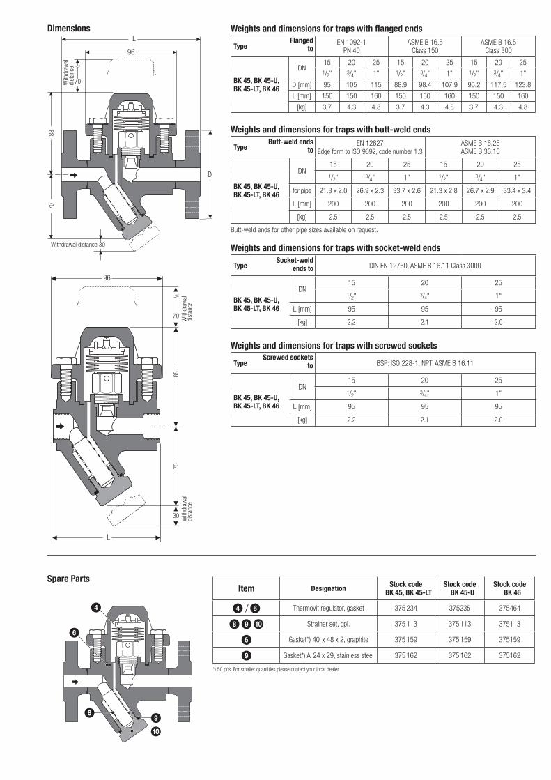
Dimensions Weights and dimensions for traps with flanged ends
Type EN 1092-1 PN 40
ASME B 16.5 Class 150
ASME B 16.5 Class 300
BK 45, BK 45-U, BK 45-LT, BK 46
DN15 20 25 15 20 25 15 20 251/2" 3/4" 1" 1/2" 3/4" 1" 1/2" 3/4" 1"
D [mm] 95 105 115 88.9 98.4 107.9 95.2 117.5 123.8
L [mm] 150 150 160 150 150 160 150 150 160
[kg] 3.7 4.3 4.8 3.7 4.3 4.8 3.7 4.3 4.8
Flangedto
Weights and dimensions for traps with butt-weld ends
Type EN 12627Edge form to ISO 9692, code number 1.3
ASME B 16.25 ASME B 36.10
BK 45, BK 45-U, BK 45-LT, BK 46
DN15 20 25 15 20 25
1/2" 3/4" 1" 1/2" 3/4" 1"
for pipe 21.3 x 2.0 26.9 x 2.3 33.7 x 2.6 21.3 x 2.8 26.7 x 2.9 33.4 x 3.4
L [mm] 200 200 200 200 200 200
[kg] 2.5 2.5 2.5 2.5 2.5 2.5
Butt-weld ends for other pipe sizes available on request.
Butt-weld ends to
Weights and dimensions for traps with screwed sockets
Type BSP: ISO 228-1, NPT: ASME B 16.11
BK 45, BK 45-U, BK 45-LT, BK 46
DN15 20 25
1/2" 3/4" 1"
L [mm] 95 95 95
[kg] 2.2 2.1 2.0
Screwed sockets to
Weights and dimensions for traps with socket-weld ends
Type DIN EN 12760, ASME B 16.11 Class 3000
BK 45, BK 45-U, BK 45-LT, BK 46
DN15 20 25
1/2" 3/4" 1"
L [mm] 95 95 95
[kg] 2.2 2.1 2.0
Socket-weld ends to
L
96
70
D
7088
Item Designation Stock code BK 45, BK 45-LT
Stock code BK 45-U
Stock code BK 46
4 / 6 Thermovit regulator, gasket 375 234 375235 375464
8 9 0 Strainer set, cpl. 375 113 375 113 375113
6 Gasket*) 40 x 48 x 2, graphite 375 159 375 159 375159
9 Gasket*) A 24 x 29, stainless steel 375 162 375 162 375162
*) 50 pcs. For smaller quantities please contact your local dealer.
7088
L
70
96
With
draw
al
dist
ance
Withdrawal distance 30
With
draw
al
dist
ance
30 With
draw
al
dist
ance
Steam TrapsBK 45, BK 45-U, BK 45-LT, BK 46PN 40DN 15, 20, 25 (½", ¾", 1")
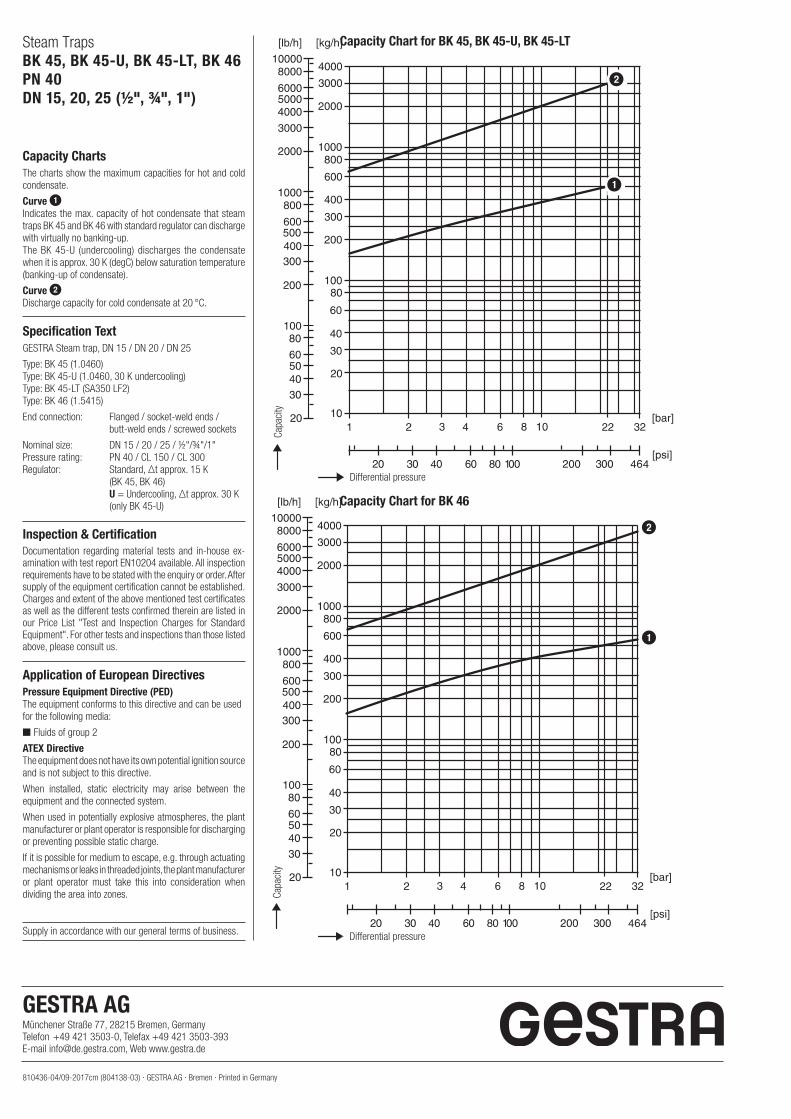
Capacity Chart for BK 45, BK 45-U, BK 45-LT
Capacity ChartsThe charts show the maximum capacities for hot and cold condensate.
Curve 1Indicates the max. capacity of hot condensate that steam traps BK 45 and BK 46 with standard regulator can discharge with virtually no banking-up.The BK 45-U (undercooling) discharges the condensate when it is approx. 30 K (degC) below saturation temperature (banking-up of condensate).
Curve 2Discharge capacity for cold condensate at 20 °C.
Specification TextGESTRA Steam trap, DN 15 / DN 20 / DN 25
Type: BK 45 (1.0460)Type: BK 45-U (1.0460, 30 K undercooling) Type: BK 45-LT (SA350 LF2) Type: BK 46 (1.5415)
End connection: Flanged / socket-weld ends / butt-weld ends / screwed sockets
Nominal size: DN 15 / 20 / 25 / ½"/¾"/1" Pressure rating: PN 40 / CL 150 / CL 300 Regulator: Standard, Δt approx. 15 K (BK 45, BK 46) U = Undercooling, Δt approx. 30 K (only BK 45-U)
Inspection & CertificationDocumentation regarding material tests and in-house ex-amination with test report EN10204 available. All inspection requirements have to be stated with the enquiry or order. After supply of the equipment certification cannot be established.Charges and extent of the above mentioned test certificates as well as the different tests confirmed therein are listed in our Price List "Test and Inspection Charges for Standard Equipment". For other tests and inspections than those listed above, please consult us.
Application of European Directives Pressure Equipment Directive (PED) The equipment conforms to this directive and can be usedfor the following media:
■ Fluids of group 2
ATEX DirectiveThe equipment does not have its own potential ignition source and is not subject to this directive.
When installed, static electricity may arise between the equipment and the connected system.
When used in potentially explosive atmospheres, the plant manufacturer or plant operator is responsible for discharging or preventing possible static charge.
If it is possible for medium to escape, e.g. through actuating mechanisms or leaks in threaded joints, the plant manufacturer or plant operator must take this into consideration when dividing the area into zones.
810436-04/09-2017cm (804138-03) · GESTRA AG · Bremen · Printed in Germany
Supply in accordance with our general terms of business.
Capacity Chart for BK 46
GESTRA AG Münchener Straße 77, 28215 Bremen, GermanyTelefon +49 421 3503-0, Telefax +49 421 3503-393E-mail [email protected], Web www.gestra.de
Differential pressure
Capa
city
Capa
city
Differential pressure
2
1
2
1

DescriptionThermostatic steam trap with corrosion-resistant Thermovit (Duo stainless steel) regulator unaffected by water hammer. The Thermovit regulator can be adjusted from the outside. With integral strainer and non-return valve action. Asbestos-free body gasket (graphite). Installation in any position. The steam trap is adjusted at our factory to discharge condensate with virtually no banking-up. More undercooling (banking-up) can be set manually from the outside during operation.
Pressure and temperature ratings/types of connection
BK 15, flange PN 40, EN 1092-1, butt-weld ends
Pressure 1) p [barg] 40 33, 3 27.6 23.8 13.1
Temperature 1) T [°C] -10/20 200 300 400 450
Max. admissible differential pressure ΔPMX [bar]
[psi]22
3191) Ratings for strength of body/cover to EN 1092-1
BK 15, flange class 300, ASME B16.5, screwed socket, socket-weld ends
Pressure 1) p [barg] 51.1 43.8 39.8 34.7 28.8
Temperature 1) T [°C] -29/38 200 300 400 425
Max. admissible differential pressure ΔPMX [bar]
[psi]22
3191) Ratings for strength of body/cover to ASME B16.5
BK 15, flange class 150, ASME B16.5
Pressure 1) p [barg] 19.6 13.8 10.2 6.5 5.5
Temperature 1) T [°C] -29/38 200 300 400 425
1) Ratings for strength of body/cover to ASME B16.5
Materials EN ASTM
Body 1.0460 A 105
Cover 1.0460 A 105
Bolts 1.7225 A 193 B 7 1)
Nuts 1.7225 A 194 B 7 1)
Body gasket Graphite
Thermovit regulator Stainless steel/Duo stainless steel
Other inner parts Stainless steel
1) Pay attention to differences from EN in chemical and physical properties.
Dimensionsand weights
Versions
EN flangesSocket-weld
endsButt-weld ends
Screwed sockets
Nominal sizes [mm]
[inch]
40 50
1½ 2
40 50
1½ 2
40 50
1½ 2
40 50
1½ 2
Length L 230 230 130 210 250 250 130 210
Butt-weld ends via transition pieces to DIN 3239
48.3 x 2.6 60.3 x 3.2
Weight approx. [kg]] 11 12.5 6.3 7.7 6.8 7.5 6.3 7.7
Steam TrapBK 15PN 40DN 40, 50 DN (11/2", 2")
BK 15 with flanges, DN 40, 50
With socket-weld ends DN 40
With butt-weld ends via transition pieces DN 40, 50
With socket-weld ends DN 50
L
115
DN
140
90
mm
b
L
Types of connectionFlanges: EN 1092-1, form B1, PN 40. ASME B 16.5, 150 RF and 300 RF.Socket-weld endsButt-weld endsScrewed sockets: G and NPT threads
*)
L
L
Data sheet 810708-01Issue: 10/17
∅ g
∅ D
∅ k
810708-01/10-2017cm (801998-02) · GESTRA AG · Bremen · Printed in Germany
CGHJ
Steam TrapBK 15PN 40DN 40, 50 DN (11/2", 2")
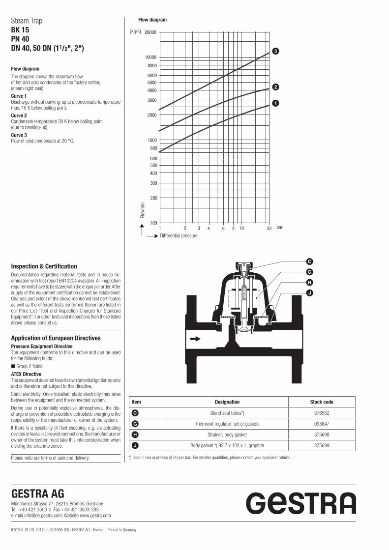
Flow diagramThe diagram shows the maximum flowof hot and cold condensate at the factory setting(steam-tight seal).
Curve 1Discharge without banking-up at a condensate temperaturemax. 10 K below boiling point.
Curve 2Condensate temperature 30 K below boiling point(due to banking-up).
Curve 3Flow of cold condensate at 20 °C.
Item Designation Stock code
C Gland seal tubes*) 376552
G Thermovit regulator, set of gaskets 098847
H Strainer, body gasket 375698
J Body gasket *) 92.7 x 102 x 1, graphite 375699
*) Sold in box quantities of 20 per box. For smaller quantities, please contact your specialist retailer.Please note our terms of sale and delivery.
Inspection & CertificationDocumentation regarding material tests and in-house ex-amination with test report EN10204 available. All inspection requirements have to be stated with the enquiry or order. After supply of the equipment certification cannot be established. Charges and extent of the above mentioned test certificates as well as the different tests confirmed therein are listed in our Price List "Test and Inspection Charges for Standard Equipment". For other tests and inspections than those listed above, please consult us.
Application of European DirectivesPressure Equipment DirectiveThe equipment conforms to this directive and can be used for the following fluids:
■ Group 2 fluids
ATEX DirectiveThe equipment does not have its own potential ignition source and is therefore not subject to this directive.
Static electricity: Once installed, static electricity may arise between the equipment and the connected system.
During use in potentially explosive atmospheres, the dis-charge or prevention of possible electrostatic charging is the responsibility of the manufacturer or owner of the system.
If there is a possibility of fluid escaping, e.g. via actuating devices or leaks in screwed connections, the manufacturer or owner of the system must take this into consideration when dividing the area into zones.
3
2
1
Flow diagram
Flow
rate
Differential pressure
bar
GESTRA AG Münchener Strasse 77, 28215 Bremen, GermanyTel. +49 421 3503-0, Fax +49 421 3503-393e-mail [email protected], Website www.gestra.com
[kg/h]
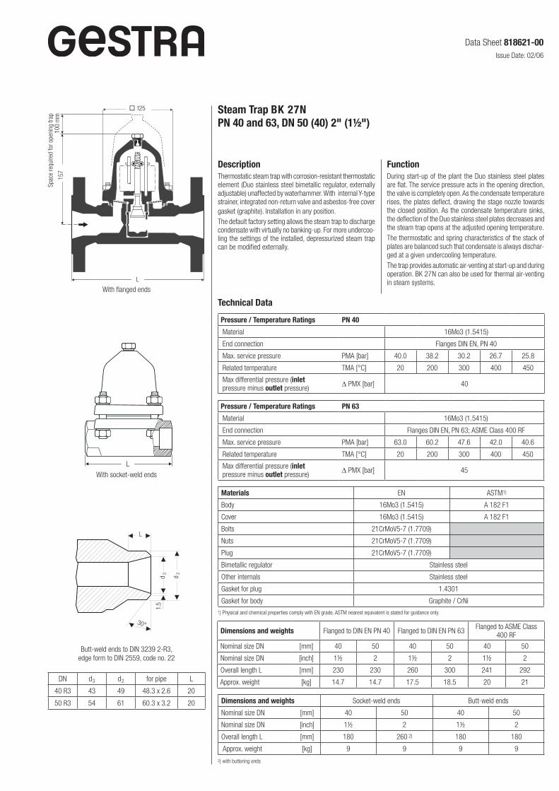
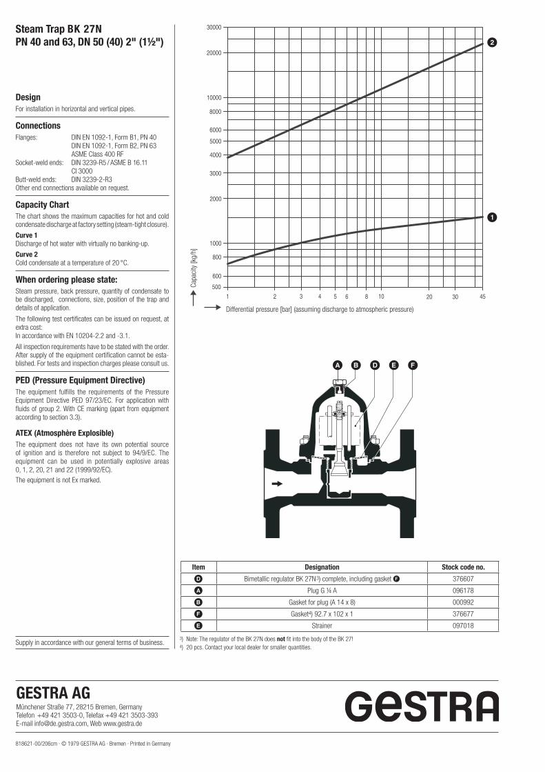
Steam Trap BK 27N PN 40 and 63, DN 50 (40) 2" (1½")
DescriptionThermostatic steam trap with corrosion-resistant thermostatic element (Duo stainless steel bimetallic regulator, externally adjustable) unaffected by waterhammer. With internal Y-type strainer, integrated non-return valve and asbestos-free cover gasket (graphite). Installation in any position.The default factory setting allows the steam trap to discharge condensate with virtually no banking-up. For more undercoo-ling the settings of the installed, depressurized steam trap can be modified externally.
Spac
e re
quire
d fo
r ope
ning
trap
10
0 m
m15
7
L
With flanged ends
L
With socket-weld ends
Butt-weld ends to DIN 3239 2-R3, edge form to DIN 2559, code no. 22
d2
d3
125
Materials EN ASTM1)
Body 16Mo3 (1.5415) A 182 F1
Cover 16Mo3 (1.5415) A 182 F1
Bolts 21CrMoV5-7 (1.7709)
Nuts 21CrMoV5-7 (1.7709)
Plug 21CrMoV5-7 (1.7709)
Bimetallic regulator Stainless steel
Other internals Stainless steel
Gasket for plug 1.4301
Gasket for body Graphite / CrNi1) Physical and chemical properties comply with EN grade. ASTM nearest equivalent is stated for guidance only.
Dimensions and weights Flanged to DIN EN PN 40 Flanged to DIN EN PN 63 Flanged to ASME Class 400 RF
Nominal size DN [mm] 40 50 40 50 40 50
Nominal size DN [inch] 1½ 2 1½ 2 1½ 2
Overall length L [mm] 230 230 260 300 241 292
Approx. weight [kg] 14.7 14.7 17.5 18.5 20 21
Dimensions and weights Socket-weld ends Butt-weld ends
Nominal size DN [mm] 40 50 40 50
Nominal size DN [inch] 1½ 2 1½ 2
Overall length L [mm] 180 260 2) 180 180
Approx. weight [kg] 9 9 9 9
2) with buttering ends
1.5
DN d3 d2 for pipe L
40 R3 43 49 48.3 x 2.6 20
50 R3 54 61 60.3 x 3.2 20
30°
Pressure / Temperature Ratings PN 40
Material 16Mo3 (1.5415)
End connection Flanges DIN EN, PN 40
Max. service pressure PMA [bar] 40.0 38.2 30.2 26.7 25.8
Related temperature TMA [°C] 20 200 300 400 450
Max differential pressure (inlet pressure minus outlet pressure) D PMX [bar] 40
FunctionDuring start-up of the plant the Duo stainless steel plates are flat. The service pressure acts in the opening direction, the valve is completely open. As the condensate temperature rises, the plates deflect, drawing the stage nozzle towards the closed position. As the condensate temperature sinks, the deflection of the Duo stainless steel plates decreases and the steam trap opens at the adjusted opening temperature.The thermostatic and spring characteristics of the stack of plates are balanced such that condensate is always dischar-ged at a given undercooling temperature.The trap provides automatic air-venting at start-up and during operation. BK 27N can also be used for thermal air-venting in steam systems.
Technical Data
L
Pressure / Temperature Ratings PN 63
Material 16Mo3 (1.5415)
End connection Flanges DIN EN, PN 63; ASME Class 400 RF
Max. service pressure PMA [bar] 63.0 60.2 47.6 42.0 40.6
Related temperature TMA [°C] 20 200 300 400 450
Max differential pressure (inlet pressure minus outlet pressure) D PMX [bar] 45
Data Sheet 818621-00Issue Date: 02/06
818621-00/206cm · © 1979 GESTRA AG · Bremen · Printed in Germany
Supply in accordance with our general terms of business.
Steam Trap BK 27N PN 40 and 63, DN 50 (40) 2" (1½")
DesignFor installation in horizontal and vertical pipes.
ConnectionsFlanges: DIN EN 1092-1, Form B1, PN 40 DIN EN 1092-1, Form B2, PN 63 ASME Class 400 RF Socket-weld ends: DIN 3239-R5 / ASME B 16.11 CI 3000 Butt-weld ends: DIN 3239-2-R3Other end connections available on request.
Capacity ChartThe chart shows the maximum capacities for hot and cold condensate discharge at factory setting (steam-tight closure).
Curve 1Discharge of hot water with virtually no bank ing-up.
Curve 2Cold condensate at a temperature of 20 °C.
When ordering please state:Steam pressure, back pressure, quantity of condensate to be discharged, connections, size, position of the trap and details of application.
The following test certificates can be issued on request, at extra cost:In accordance with EN 10204-2.2 and -3.1.
All inspection requirements have to be stated with the order. After supply of the equipment certification cannot be esta-blished. For tests and inspection charges please consult us.
PED (Pressure Equipment Directive)The equipment fulfills the requirements of the Pressure Equipment Directive PED 97/23/EC. For application with fluids of group 2. With CE marking (apart from equipment according to section 3.3).
ATEX (Atmosphère Explosible) The equipment does not have its own potential source of ignition and is therefore not subject to 94/9/EC. The equipment can be used in potentially explosive areas 0, 1, 2, 20, 21 and 22 (1999/92/EC). The equipment is not Ex marked.
Differential pressure [bar] (assuming discharge to atmospheric pressure)
Capa
city
[kg/
h]
3) Note: The regulator of the BK 27N does not fit into the body of the BK 27! 4) 20 pcs. Contact your local dealer for smaller quantities.
A B D E F
Item Designation Stock code no.
D Bimetallic regulator BK 27N3) complete, including gasket F 376607
A Plug G ¼ A 096178
B Gasket for plug (A 14 x 8) 000992
F Gasket4) 92.7 x 102 x 1 376677
E Strainer 097018
1
2
GESTRA AG Münchener Straße 77, 28215 Bremen, GermanyTelefon +49 421 3503-0, Telefax +49 421 3503-393E-mail [email protected], Web www.gestra.de
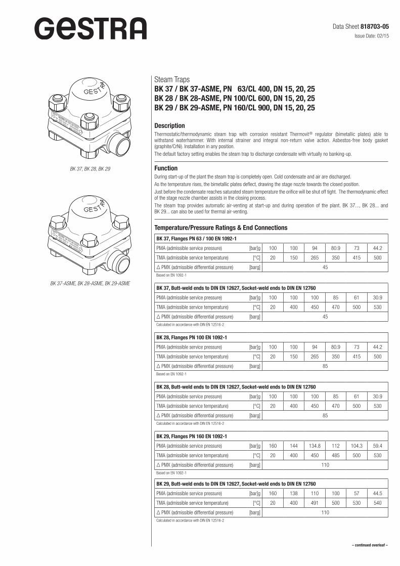
Steam TrapsBK 37 / BK 37-ASME, PN 63/CL 400, DN 15, 20, 25BK 28 / BK 28-ASME, PN 100/CL 600, DN 15, 20, 25BK 29 / BK 29-ASME, PN 160/CL 900, DN 15, 20, 25
DescriptionThermostatic/thermodynamic steam trap with corrosion resistant Thermovit® regulator (bimetallic plates) able to withstand waterhammer. With internal strainer and integral non-return valve action. Asbestos-free body gasket (graphite/CrNi). Installation in any position.The default factory setting enables the steam trap to discharge condensate with virtually no banking-up.
FunctionDuring start-up of the plant the steam trap is completely open. Cold condensate and air are discharged.As the temperature rises, the bimetallic plates deflect, drawing the stage nozzle towards the closed position.Just before the condensate reaches saturated steam temperature the orifice will be shut off tight. The thermodynamic effect of the stage nozzle chamber assists in the closing process.The steam trap provides automatic air-venting at start-up and during operation of the plant. BK 37..., BK 28... and BK 29... can also be used for thermal air-venting.
Temperature/Pressure Ratings & End Connections
BK 37, Flanges PN 63 / 100 EN 1092-1
PMA (admissible service pressure) [bar]g 100 100 94 80.9 73 44.2
TMA (admissible service temperature) [°C] 20 150 265 350 415 500
Δ PMX (admissible differential pressure) [barg] 45Based on EN 1092-1
BK 37, Butt-weld ends to DIN EN 12627, Socket-weld ends to DIN EN 12760
PMA (admissible service pressure) [bar]g 100 100 100 85 61 30.9
TMA (admissible service temperature) [°C] 20 400 450 470 500 530
Δ PMX (admissible differential pressure) [barg] 45Calculated in accordance with DIN EN 12516-2
BK 28, Flanges PN 100 EN 1092-1
PMA (admissible service pressure) [bar]g 100 100 94 80.9 73 44.2
TMA (admissible service temperature) [°C] 20 150 265 350 415 500
Δ PMX (admissible differential pressure) [barg] 85Based on EN 1092-1
BK 28, Butt-weld ends to DIN EN 12627, Socket-weld ends to DIN EN 12760
PMA (admissible service pressure) [bar]g 100 100 100 85 61 30.9
TMA (admissible service temperature) [°C] 20 400 450 470 500 530
Δ PMX (admissible differential pressure) [barg] 85Calculated in accordance with DIN EN 12516-2
BK 29, Flanges PN 160 EN 1092-1
PMA (admissible service pressure) [bar]g 160 144 134.8 112 104.3 59.4
TMA (admissible service temperature) [°C] 20 400 450 485 500 530
Δ PMX (admissible differential pressure) [barg] 110Based on EN 1092-1
BK 29, Butt-weld ends to DIN EN 12627, Socket-weld ends to DIN EN 12760
PMA (admissible service pressure) [bar]g 160 138 110 100 57 44.5
TMA (admissible service temperature) [°C] 20 400 491 500 530 540
Δ PMX (admissible differential pressure) [barg] 110Calculated in accordance with DIN EN 12516-2
– continued overleaf –
BK 37, BK 28, BK 29
BK 37-ASME, BK 28-ASME, BK 29-ASME
Data Sheet 818703-05Issue Date: 02/15
BK 37-ASME, Flanges B16.5 Class 400/600, Butt-weld ends to B16.25 Sched. 80, Socket-weld ends to B16.11 Class 3000
PMA (admissible service pressure) [barg] 103.4 100.9 85.7 73.3 67.7 42.8
TMA (admissible service temperature) [°C] 20 100 300 400 450 500
PMA (admissible service pressure) [psi] 1500 1400 1210 1065 975 745
TMA (admissible service temperature) [°F] 100 300 600 750 850 900
Δ PMX (admissible differential pressure)[barg] 45
[psi] 652
Calculated in accordance with ASME B16.34
BK 28-ASME, Flanges B16.5 Class 600, Butt-weld ends to B16.25 Sched. 80, Socket-weld ends to B16.11 Class 3000
PMA (admissible service pressure) [barg] 103.4 100.9 85.7 73.3 67.7 42.8
TMA (admissible service temperature) [°C] 20 100 300 400 450 500
PMA (admissible service pressure) [psi] 1500 1400 1210 1065 975 745
TMA (admissible service temperature) [°F] 100 300 600 750 850 900
Δ PMX (admissible differential pressure)[barg] 85
[psi] 1232
Calculated in accordance with ASME B16.34
BK 29-ASME, Flanges B16.5 Class 900/1500, Butt-weld ends to B16.25 Sched. 160, Socket-weld ends to B16.11 Class 6000
PMA (admissible service pressure) [barg] 155.1 128.6 101.4 64.1 45.9 40.2
TMA (admissible service temperature) [°C] 20 300 450 500 530 540
PMA (admissible service pressure) [psi] 2250 1815 1460 1120 825 595
TMA (admissible service temperature) [°F] 100 600 850 900 950 1000
Δ PMX (admissible differential pressure)[barg] 110
[psi] 1595
Calculated in accordance with ASME B16.34
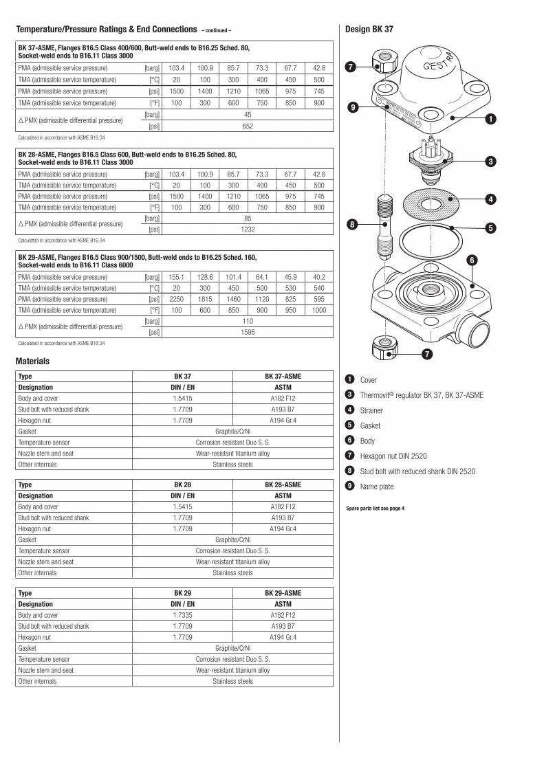
Temperature/Pressure Ratings & End Connections – continued – Design BK 37
1 Cover
3 Thermovit® regulator BK 37, BK 37-ASME
4 Strainer
5 Gasket
6 Body
7 Hexagon nut DIN 2520
8 Stud bolt with reduced shank DIN 2520
9 Name plate
Spare parts list see page 4
1
5
4
3
6
7
9
7
8
Materials
Type BK 37 BK 37-ASME
Designation DIN / EN ASTM
Body and cover 1.5415 A182 F12
Stud bolt with reduced shank 1.7709 A193 B7
Hexagon nut 1.7709 A194 Gr.4
Gasket Graphite/CrNi
Temperature sensor Corrosion resistant Duo S. S.
Nozzle stem and seat Wear-resistant titanium alloy
Other internals Stainless steels
Type BK 28 BK 28-ASME
Designation DIN / EN ASTM
Body and cover 1.5415 A182 F12
Stud bolt with reduced shank 1.7709 A193 B7
Hexagon nut 1.7709 A194 Gr.4
Gasket Graphite/CrNi
Temperature sensor Corrosion resistant Duo S. S.
Nozzle stem and seat Wear-resistant titanium alloy
Other internals Stainless steels
Type BK 29 BK 29-ASME
Designation DIN / EN ASTM
Body and cover 1.7335 A182 F12
Stud bolt with reduced shank 1.7709 A193 B7
Hexagon nut 1.7709 A194 Gr.4
Gasket Graphite/CrNi
Temperature sensor Corrosion resistant Duo S. S.
Nozzle stem and seat Wear-resistant titanium alloy
Other internals Stainless steels
L
y 110
(4.33")80
(3.1
5")
115
(5.9
1)
92 (3
.622
)
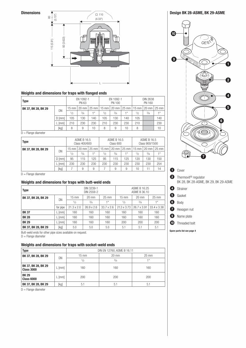
Dimensions Design BK 28-ASME, BK 29-ASME
1 Cover
2 Thermovit® regulator BK 28, BK 28-ASME, BK 29, BK 29-ASME
4 Strainer
5 Gasket
6 Body
7 Hexagon nut
9 Name plate
0 Threaded bolt
Spare parts list see page 4
1
5
4
2
6
7
9
0
Weights and dimensions for traps with socket-weld endsType DIN EN 12760, ASME B 16.11
BK 37, BK 28, BK 29DN
15 mm 20 mm 25 mm1/2 3/4 1"
BK 37, BK 28, BK 29Class 3000 L [mm] 160 160 160
BK 29Class 6000 L [mm] 200 200 200
BK 37, BK 28, BK 29 [kg] 5.1 5.1 5.1
D = Flange diameter
Weights and dimensions for traps with butt-weld ends
Type DIN 3239-1DIN 2559-2
ASME B 16.25 ASME B 36.10
BK 37, BK 28, BK 29DN
15 mm 20 mm 25 mm 15 mm 20 mm 25 mm1/2 3/4 1" 1/2 3/4 1"
for pipe 21.3 x 2.0 26.9 x 2.6 33.7 x 2.6 21.3 x 3.73 26.7 x 3.91 33.4 x 3.38
BK 37 L [mm] 160 160 160 160 160 160
BK 28 L [mm] 160 160 160 160 160 160
BK 29 L [mm] 160 160 160 200 200 200
BK 37, BK 28, BK 29 [kg] 5.0 5.0 5.0 5.1 5.1 5.1
Butt-weld ends for other pipe sizes available on request.D = Flange diameter
Weights and dimensions for traps with flanged ends
Type EN 1092-1 PN 63
EN 1092-1 PN 100
DIN 2638 PN 160
BK 37, BK 28, BK 29DN
15 mm 20 mm 25 mm 15 mm 20 mm 25 mm 15 mm 20 mm 25 mm1/2 3/4 1" 1/2 3/4 1" 1/2 3/4 1"
D [mm] 105 130 140 105 130 140 105 140
L [mm] 210 230 230 210 230 230 210 230
[kg] 8 9 10 8 9 10 8 10
D = Flange diameter
Type ASME B 16.5 Class 400/600
ASME B 16.5 Class 600
ASME B 16.5Class 900/1500
BK 37, BK 28, BK 29DN
15 mm 20 mm 25 mm 15 mm 20 mm 25 mm 15 mm 20 mm 25 mm1/2 3/4 1" 1/2 3/4 1" 1/2 3/4 1"
D [mm] 95 115 125 95 115 125 120 130 150
L [mm] 230 230 230 230 230 230 230 230 254
[kg] 7 9 9 7 9 9 10 11 14
D = Flange diameter
Steam trapsBK 37 / BK 37-ASMEBK 28 / BK 28-ASME BK 29 / BK 29-ASME
818703-05/02-2015cm (804011-10) · GESTRA AG · Bremen · Printed in Germany
Supply in accordance with our general terms of business.
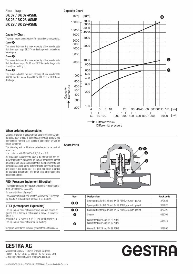
Capacity ChartThe chart shows the capacities for hot and cold condensate.
Curve 1
This curve indicates the max. capacity of hot condensate that the steam trap BK 37 can discharge with virtually no banking up.
Curve 2
This curve indicates the max. capacity of hot condensate that the steam traps BK 28 and BK 29 can discharge with virtually no banking up.
Curve 3
This curve indicates the max. capacity of cold condensate (20 °C) that the steam traps BK 37, BK 28 and BK 29 can discharge.
When ordering please state:Material, material of screws/bolts, steam pressure & tem-perature, back pressure, condensate flowrate, design, end connections, nominal size, details of application or type of steam consumer.The following test certificates can be issued on request, at extra cost:In accordance with EN 10204-2.2, 3.1 and 3.2.All inspection requirements have to be stated with the en-quiry/order. After supply of the equipment certification cannot be established. Charges and extent of the above mentioned certificates as well as the different tests confirmed therein are listed in our price list "Test and Inspection Charges for Standard Equipment". For other tests and inspections please consult us.
PED (Pressure Equipment Directive)The equipment fulfils the requirements of the Pressure Equip-ment Directive PED 97/23/EC.For use with fluids of group 2.The equipment is excluded from the scope of the PED accord-ing to Article 3.3 and must not bear a CE marking.
ATEX (Atmosphère Explosible)The equipment does not have ist own potential source of ignition and is therefore not subject to the ATEX Directive 94/9/EC. Applicable in Ex zones 0, 1, 2, 20, 21, 22 (1999/92/EC). The equipment does not bear an Ex marking.
Capacity Chart
Spare Parts3/4
5
6
Item Designation Stock code
3, 6Spare part kit for BK 28 and BK 28 ASME, cpl. with gasket 379825
Spare part kit for BK 29 and BK 29 ASME, cpl. with gasket 379826
4, 6 Spare part kit for BK 37 and BK 37 ASME, cpl. with gasket 377722
5 Strainer 096701
6Gasket for BK 28 and BK 28 ASMEGasket for BK 37 and BK 37 ASME 086519
Gasket for BK 29 and BK 29 ASME 372095
[kg/h][lb/h]
1000
2000
3000
4000
50006000
8000
10000
15000
600
800
400
500
300
200100
4000
50006000
3000
2000
1000
7000
600
800
400
500
300
200
20001000600 800400
20
300
10
100
100110 1506
60
60 808
80
304 40 45
200
[bar]
[psi]
DifferenzdruckDifferential pressure
Cap
acity
Dur
chflu
ss
3
2
1
GESTRA AG Münchener Straße 77, 28215 Bremen, GermanyTelefon +49 421 3503-0, Telefax +49 421 3503-393E-mail [email protected], Web www.gestra.de