Embed Size (px)
Citation preview
A
B
Description of PL7 software
Detailed description of instructions and functionsReferencemanual

___________________________________________________________________________
B/2
___________________________________________________________________________A/1
A
Description of PL7 Contentssoftware Part A
Section Page
___________________________________________________________________________
1 General information A1/1
1.1 Presentation of PL7 software A1/11.1-1 Presentation A1/11.1-2 Single task structure A1/31.1-3 Multitask structure A1/31.1-4 Structured and modular programming A1/41.1-5 Structuring as function modules A1/51.1-6 Symbolic programming A1/61.1-7 PL7 instructions A1/81.1-8 User function blocks A1/9
1.2 Addressable objects A1/101.2-1 Definition of the main Boolean objects A1/101.2-2 Addressing TSX 37 I/O module objects A1/111.2-3 Addressing TSX/PMX/PCX 57 I/O module objects A1/131.2-4 Addressing words A1/161.2-5 Function block objects A1/201.2-6 Structured objects A1/211.2-7 Grafcet objects A1/231.2-8 DFB objects A1/231.2-9 Symbolization A1/24
1.3 User memory A1/261.3-1 General A1/261.3-2 Saving / retrieving internal words %MWi A1/281.3-3 Bit memory A1/291.3-4 Word memory A1/311.3-5 TSX 37-10/21/22 PLCs A1/321.3-6 TSX/PCX/PMX 57-10/20/25 PLCs A1/331.3-7 TSX/PCX 57-30/35 PLCs A1/341.3-8 PMX57-35/45 and TSX 57-40/45 PLCs A1/35
___________________________________________________________________________
A/2
A
Description of PL7 Contentssoftware Part A
Section Page
________________________________________________________________
1.4 Operating modes A1/361.4-1 Processing on power outage and power return A1/361.4-2 Processing on a warm restart A1/371.4-3 Processing on a cold start A1/38
1.5 Single task software structure A1/391.5-1 Presentation of the master task A1/391.5-2 Cyclic execution A1/411.5-3 Periodic execution A1/421.5-4 Monitoring the scan time A1/44
1.6 Multitask software structure A1/451.6-1 Description A1/451.6-2 Master task A1/471.6-3 Fast task A1/481.6-4 Assigning I/O channels to the master and fast tasks A1/491.6-5 Event-triggered tasks A1/50
2 Ladder language A2/1
2.1 Presentation of Ladder language A2/12.1-1 Principle A2/12.1-2 Graphic elements A2/2
2.2 Structure of a rung A2/52.2-1 General A2/52.2-2 Labels A2/62.2-3 Comments A2/62.2-4 Rungs A2/72.2-5 Rungs with function and operation blocks A2/10
2.3 Rules for executing rungs A2/132.3-1 Principle for executing a rung A2/13
___________________________________________________________________________A/3
A
Description of PL7 Contentssoftware Part A
Section Page
___________________________________________________________________________
3 Instruction List language A3/1
3.1 Presentation of Instruction List language A3/13.1-1 Principle A3/13.1-2 Instructions A3/2
3.2 Program structure A3/43.2-1 General A3/43.2-2 Comments A3/43.2-3 Labels A3/43.2-4 Using parentheses A3/53.2-5 MPS, MRD and MPP instructions A3/73.2-6 Principles for programming predefined function blocks A3/8
3.3 Rules for executing Instruction List programs A3/9
4 Structured Text language A4/1
4.1 Presentation of Structured Text language A4/14.1-1 Principle A4/14.1-2 Instructions A4/2
4.2 Program structure A4/74.2-1 General A4/74.2-2 Comment A4/74.2-3 Label A4/84.2-4 Instructions A4/84.2-5 Control structures A4/9
4.3 Rules for executing a Structured Text program A4/15
___________________________________________________________________________
A/4
A
Description of PL7 Contentssoftware Part A
Section Page
________________________________________________________________
5 Grafcet language A5/1
5.1 Presentation of Grafcet language A5/15.1-1 Reminder of principles of Grafcet A5/15.1-2 Progressive analysis : macro-representations A5/2
5.2 Graphic symbols specific to Grafcet language A5/4
5.3 Objects specific to Grafcet A5/6
5.4 Grafcet language possibilities A5/7
5.5 Grafcet chart representation A5/9
5.6 Macro-steps A5/155.6-1 Principle A5/155.6-2 Characteristics A5/165.6-3 Initial steps A5/16
5.7 Actions associated with steps A5/17
5.8 Conditions associated with transitions A5/20
5.9 Organization of the Grafcet section A5/235.9-1 Description of the Grafcet section A5/235.9-2 Preprocessing A5/245.9-3 The use of system bits in preprocessing A5/255.9-4 Sequential processing A5/285.9-5 Post-processing A5/30
___________________________________________________________________________A/5
A
Description of PL7 Contentssoftware Part A
Section Page
___________________________________________________________________________
6 DFBs A6/1
6.1 Presentation of DFBs A6/16.1-1 General A6/16.1-2 Setting up a DFB A6/2
6.2 Designing a DFB type A6/36.2-1 Creating a DFB type A6/36.2-2 Description of parameters and variables A6/36.2-3 DFB type code A6/56.2-4 Confirming the DFB type A6/66.2-5 DFB type properties A6/66.2-6 Descriptive file A6/76.2-7 DFB type properties A6/76.2-8 Importing/exporting a DFB type A6/7
6.3 Creating a DFB type instance A6/86.3-1 Principles A6/8
6.4 Using DFBs A6/96.4-1 General programming rules A6/96.4-2 Programming in Ladder language A6/106.4-3 Programming in Structured Text language or
Instruction List language A6/116.4-4 Accessing variables A6/126.4-5 Saving and restoring public variables A6/126.4-6 Executing DFBs A6/12
6.5 Example A6/13
___________________________________________________________________________
A/6
A
Description of PL7 Contentssoftware Part A
Section Page
________________________________________________________________
7 Function modules A7/1
7.1 Presentation of function modules A7/17.1-1 Definition of a function module A7/17.1-2 Representation of a function module in PL7 PRO A7/27.1-3 The concept of a function submodule A7/37.1-4 The attributes of a function module A7/3
7.2 Setting up function modules A7/47.2-1 Creating a function module A7/47.2-2 Modifying the architecture of function modules A7/4
7.3 Programming a function module A7/67.3-1 Adding / creating a section, an event or a macro-step in
a function module A7/67.3-2 Deleting a section, a macro-step or an event in a module A7/87.3-3 Adding / creating an animation table in a function module A7/97.3-4 Entering / modifying the descriptive file A7/9
7.4 Executing the program A7/10
7.5 Debugging the application A7/10
7.6 Application documentation file A7/10
7.7 Importing and exporting the source file for a function module A7/117.7-1 Exporting A7/117.7-2 Importing A7/11
PL7 general information 1
___________________________________________________________________________1/1
A
1.1 Presentation of PL7 software
1.1-1 Presentation
PL7 Junior software is the programming software for TSX 37 and TSX/PMX/PCX 57PLCs operating under Windows. PL7 Micro software can only be used to programTSX 37 PLCs.PL7 Pro software offers, in addition to the functions provided by PL7 Junior software,the possibility of creating DFB (Derived Function Block) user function blocks, runtimescreens and function modules.PL7 Prodyn software is an operating tool (control, diagnostics, maintenance) forTSX 37 and TSX/PMX/PCX 57 PLCs. It cannot be used to create or modify anapplication.
PL7 software (1) offers :
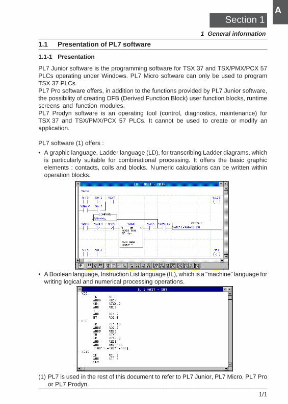
• A graphic language, Ladder language (LD), for transcribing Ladder diagrams, whichis particularly suitable for combinational processing. It offers the basic graphicelements : contacts, coils and blocks. Numeric calculations can be written withinoperation blocks.
• A Boolean language, Instruction List language (IL), which is a "machine" language forwriting logical and numerical processing operations.
(1) PL7 is used in the rest of this document to refer to PL7 Junior, PL7 Micro, PL7 Proor PL7 Prodyn.
Section 11 General information
1/2___________________________________________________________________________
A
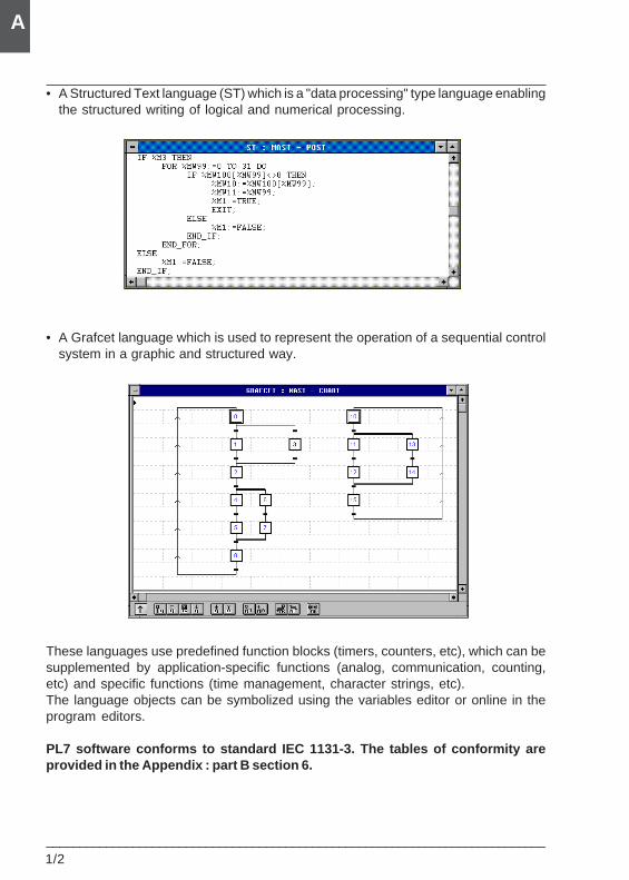
• A Structured Text language (ST) which is a "data processing" type language enablingthe structured writing of logical and numerical processing.
• A Grafcet language which is used to represent the operation of a sequential controlsystem in a graphic and structured way.
These languages use predefined function blocks (timers, counters, etc), which can besupplemented by application-specific functions (analog, communication, counting,etc) and specific functions (time management, character strings, etc).The language objects can be symbolized using the variables editor or online in theprogram editors.
PL7 software conforms to standard IEC 1131-3. The tables of conformity areprovided in the Appendix : part B section 6.
PL7 general information 1
___________________________________________________________________________1/3
A
1.1-2 Single task structure
This is the default structure of the software. It comprises a single task, the master task.
Master taskThis task can either be a periodic, said to be cyclic (the default choice), or periodic.For cyclic operation, the tasks are linked one to the other, without pausing.For periodic operation, tasks are linked at a period fixed by the user.
1.1-3 Multitask structure
The multitask structure of TSX 37 and TSX 57 PLCs enables better use which giveshigh-performance realtime applications by associating a specific program with eachapplication. Each of these programs is controlled by a task.These tasks are independent and executed in "parallel" by the main processor whichmanages their priority as well as their execution.
The aim of this type of structure is to :• Optimize use of processing power.• Simplify design and debugging. Each task is written and debugged independently of
the others.• Structure the application. Each task has a unique function.• Optimize availability.
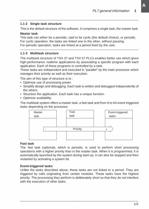
The multitask system offers a master task, a fast task and from 8 to 64 event-triggeredtasks depending on the processor.
Fast taskThe fast task (optional), which is periodic, is used to perform short processingoperations with a higher priority than in the master task. When it is programmed, it isautomatically launched by the system during start-up. It can also be stopped and thenrestarted by activating a system bit.
Event-triggered tasksUnlike the tasks described above, these tasks are not linked to a period. They aretriggered by calls originating from certain modules. These tasks have the highestpriority. The processing they perform is deliberately short so that they do not interferewith the execution of other tasks.
Fasttask
Priority
Mastertask
Event-triggered tasks
+-
1/4___________________________________________________________________________
A
1.1-4 Structured and modular programming
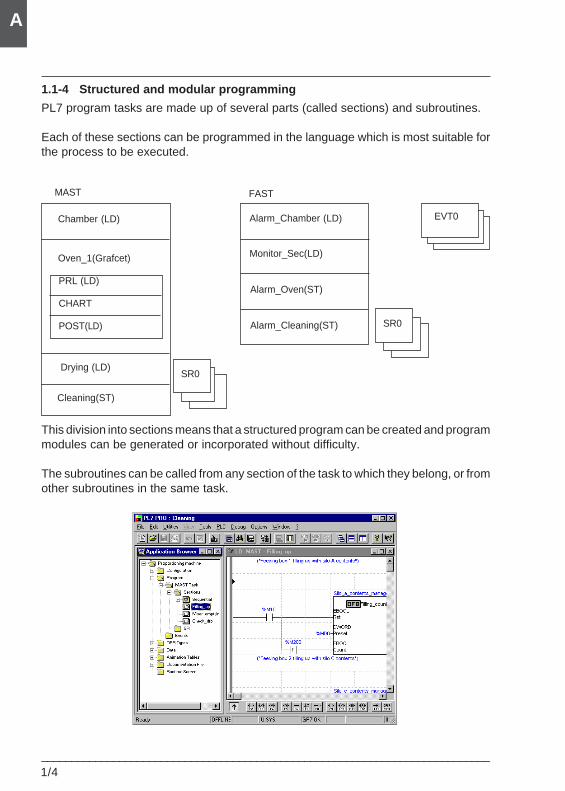
PL7 program tasks are made up of several parts (called sections) and subroutines.
Each of these sections can be programmed in the language which is most suitable forthe process to be executed.
This division into sections means that a structured program can be created and programmodules can be generated or incorporated without difficulty.
The subroutines can be called from any section of the task to which they belong, or fromother subroutines in the same task.
Chamber (LD)
MAST
Oven_1(Grafcet)
PRL (LD)
CHART
POST(LD)
Drying (LD)
Cleaning(ST)
FAST
Alarm_Chamber (LD)
Monitor_Sec(LD)
Alarm_Oven(ST)
Alarm_Cleaning(ST)
SR0
SR0
EVT0
PL7 general information 1
___________________________________________________________________________1/5
A
1.1-5 Structuring as function modules
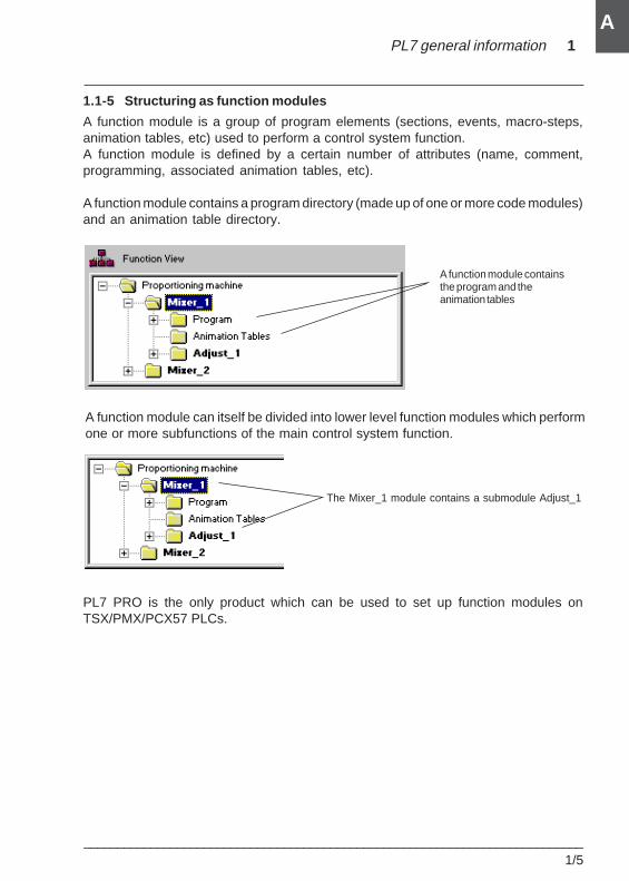
A function module is a group of program elements (sections, events, macro-steps,animation tables, etc) used to perform a control system function.A function module is defined by a certain number of attributes (name, comment,programming, associated animation tables, etc).
A function module contains a program directory (made up of one or more code modules)and an animation table directory.
A function module containsthe program and theanimation tables
A function module can itself be divided into lower level function modules which performone or more subfunctions of the main control system function.
PL7 PRO is the only product which can be used to set up function modules onTSX/PMX/PCX57 PLCs.
The Mixer_1 module contains a submodule Adjust_1
1/6___________________________________________________________________________
A
1.1-6 Symbolic programming
The user can enter or display objects :
• either by their address (for example : %Q2.5),
• or by a character string (32 characters max) known as a symbol (for exampleFc_door).
NoteThe objects associated with the DFB user function block are purely symbolic objects.
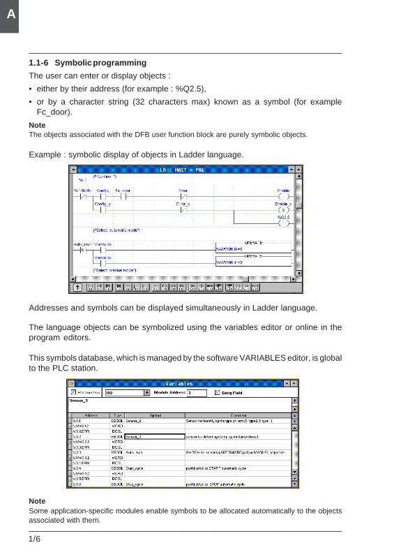
Example : symbolic display of objects in Ladder language.
Addresses and symbols can be displayed simultaneously in Ladder language.
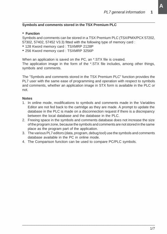
The language objects can be symbolized using the variables editor or online in theprogram editors.
This symbols database, which is managed by the software VARIABLES editor, is globalto the PLC station.
NoteSome application-specific modules enable symbols to be allocated automatically to the objectsassociated with them.
PL7 general information 1
___________________________________________________________________________1/7
A
Symbols and comments stored in the TSX Premium PLC
• FunctionSymbols and comments can be stored in a TSX Premium PLC (TSX/PMX/PCX 57202,57302, 57402, 57452 V3.3) fitted with the following type of memory card :• 128 Kword memory card : TSXMRP 2128P• 256 Kword memory card : TSXMRP 3256P
When an application is saved on the PC, an *.STX file is created.The application image in the form of the *.STX file includes, among other things,symbols and comments.
The "Symbols and comments stored in the TSX Premium PLC" function provides thePL7 user with the same ease of programming and operation with respect to symbolsand comments, whether an application image in STX form is available in the PLC ornot.
Notes1. In online mode, modifications to symbols and comments made in the Variables
Editor are not fed back to the cartridge as they are made. A prompt to update thedatabase in the PLC is made on a disconnection request if there is a discrepancybetween the local database and the database in the PLC.
2. Freeing space in the symbols and comments database does not increase the sizeof the program zone, because the symbols and comments are not stored in the sameplace as the program part of the application.
3. The various PL7 editors (data, program, debug tool) use the symbols and commentsdatabase available in the PC in online mode.
4. The Comparison function can be used to compare PC/PLC symbols.
1/8___________________________________________________________________________
A
1.1-7 PL7 instructions
All PL7 languages use the same instruction set.
Part B of this document describes all the instructions in detail. For simplicity's sake,these have been classified in 2 sets : basic instructions and advanced instructions.
Basic instructionsThey include basic Boolean instructions, predefined function blocks and arithmeticand logic instructions on integers.
Advanced instructionsThese include instructions which meet the needs of advanced programming.
They are of 2 types :
• PL7 language : these increase language processing performance through specificfunctions (manipulation of character strings, time management, etc),
• Applications : these offer functions which are specific to the application to beprocessed. For example, functions for the communication application :- PRINT to send a standard character string message to a terminal or printer.- SEND to send a message to an application.- PID : PID control function.
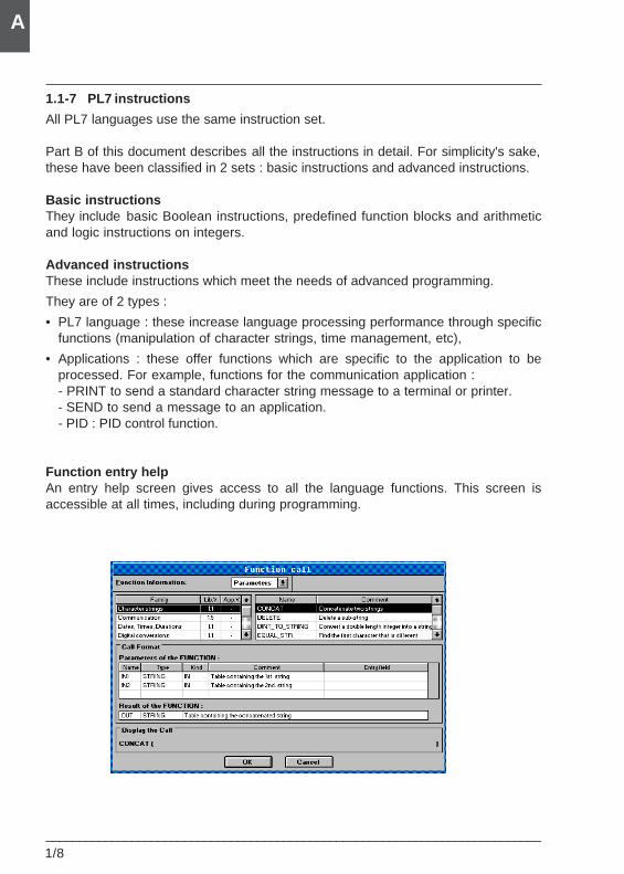
Function entry helpAn entry help screen gives access to all the language functions. This screen isaccessible at all times, including during programming.
PL7 general information 1
___________________________________________________________________________1/9
A
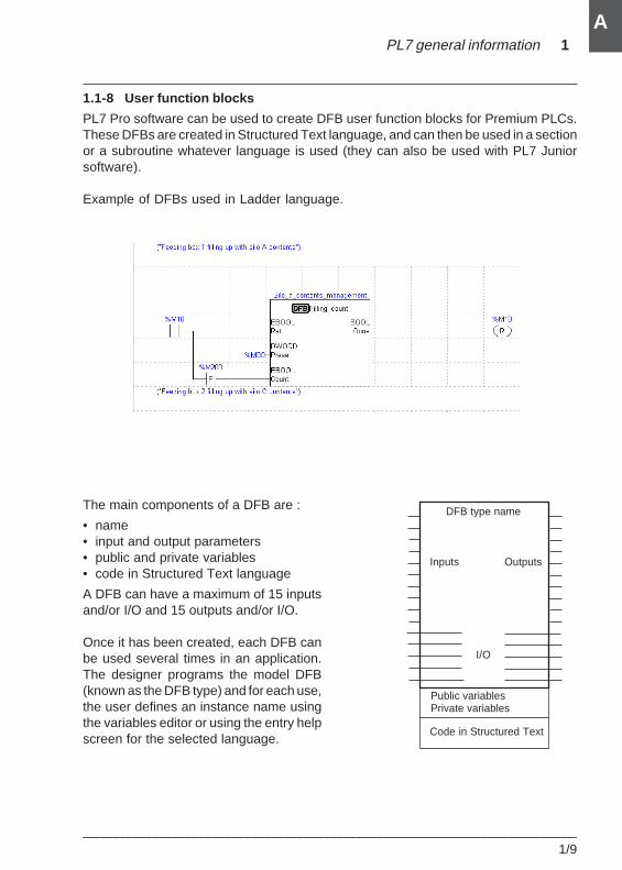
1.1-8 User function blocks
PL7 Pro software can be used to create DFB user function blocks for Premium PLCs.These DFBs are created in Structured Text language, and can then be used in a sectionor a subroutine whatever language is used (they can also be used with PL7 Juniorsoftware).
Example of DFBs used in Ladder language.
The main components of a DFB are :
• name• input and output parameters• public and private variables• code in Structured Text language
A DFB can have a maximum of 15 inputsand/or I/O and 15 outputs and/or I/O.
Once it has been created, each DFB canbe used several times in an application.The designer programs the model DFB(known as the DFB type) and for each use,the user defines an instance name usingthe variables editor or using the entry helpscreen for the selected language.
DFB type name
Inputs Outputs
I/O
Public variablesPrivate variables
Code in Structured Text
1/10___________________________________________________________________________
A
1.2 Addressable objects
1.2-1 Definition of the main Boolean objects
I/O bits
These bits are the "logical images" of the electrical state of the I/O. They are stored inthe data memory and are updated on each scan of the task in which they are configured.
Internal bitsInternal bits %Mi are used to store intermediate states during execution of the program.
Note : Unused I/O bits cannot be used as internal bits.
System bitsSystem bits %S0 to %S127 monitor correct operation of the PLC as well as progressionof the application program. The role and use of these bits are described in detail insection 3.1 of part B.
Function block bitsFunction block bits correspond to the outputs of blocks. These outputs can be eitherwired directly, or used as objects.
Word extract bitsUsing PL7 software it is possible to extract one of the 16 bits from a word object.
Grafcet step and macro-step status bitsGrafcet step status bits for steps %Xi, macro-steps %XMj and steps of macro-steps%Xj.i (Xj.IN and Xj.OUT for input and output steps of macro-steps) are used to identifythe status of Grafcet step i, macro-step j or step i of macro-step j.
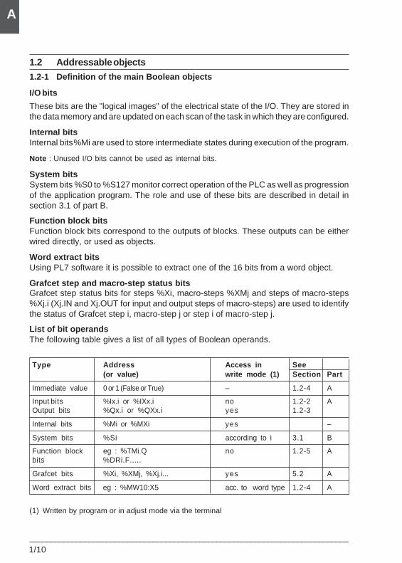
List of bit operandsThe following table gives a list of all types of Boolean operands.
Type Address Access in See(or value) write mode (1) Section Part
Immediate value 0 or 1 (False or True) – 1.2-4 A
Input bits %Ix.i or %IXx.i no 1.2-2 AOutput bits %Qx.i or %QXx.i yes 1.2-3
Internal bits %Mi or %MXi yes –
System bits %Si according to i 3.1 B
Function block eg : %TMi.Q no 1.2-5 Abits %DRi.F.....
Grafcet bits %Xi, %XMj, %Xj.i... yes 5.2 A
Word extract bits eg : %MW10:X5 acc. to word type 1.2-4 A
(1) Written by program or in adjust mode via the terminal
PL7 general information 1
___________________________________________________________________________1/11
A
ExtensionBaseBase Extension
8
7 9
06
5
10
TSX 37-10 TSX 37-21/22
6 8
5 7
2
1
4
3
2
1
4
3
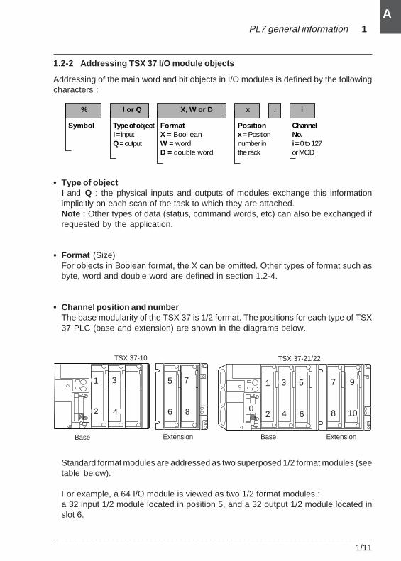
% I or Q X, W or D x . i
Symbol Type of objectI = inputQ =output
FormatX = Bool eanW = wordD = double word
Positionx= Position number in the rack
Channel No.i = 0 to 127or MOD
1.2-2 Addressing TSX 37 I/O module objects
Addressing of the main word and bit objects in I/O modules is defined by the followingcharacters :
• Type of objectI and Q : the physical inputs and outputs of modules exchange this informationimplicitly on each scan of the task to which they are attached.Note : Other types of data (status, command words, etc) can also be exchanged ifrequested by the application.
• Format (Size)For objects in Boolean format, the X can be omitted. Other types of format such asbyte, word and double word are defined in section 1.2-4.
• Channel position and numberThe base modularity of the TSX 37 is 1/2 format. The positions for each type of TSX37 PLC (base and extension) are shown in the diagrams below.
Standard format modules are addressed as two superposed 1/2 format modules (seetable below).
For example, a 64 I/O module is viewed as two 1/2 format modules :a 32 input 1/2 module located in position 5, and a 32 output 1/2 module located inslot 6.
1/12___________________________________________________________________________
A
Module 1/2 format Standard format4 Q 8 Q 12 I 28 I/O 32 I 32 Q 64 I/O
Channel number : i 0 to 3 0 to 7 0 to 11 0 to 15 0 to 15 0 to 15 0 to 31
0 to 11 0 to 15 0 to 15 0 to 31
Position and ch. no. x.0 x.0 x.0 x.0 x.0 x.0 x.0(x = position) to to to to to to to
x.3 x.7 x.11 x.15 x.15 x.15 x.31
(x+1).0 (x+1).0 (x+1).0 (x+1).0to to to to(x+1).11 (x+1).15 (x+1).15 (x+1).31
Note :The channel number can be replaced by "MOD" to access data which is general to the module.
• Rank : an optional suffix can be added after the channel number. This is used todistinguish different objects of the same type associated with the same channel.ERR : indicates a module or channel fault.Examples :%I4.MOD.ERR : information on fault in module 4%I4.3.ERR : information on fault in channel 3 of module 4.
Note :For an addressing operation across the network or for remote I/O addressing, the full access pathto the station is added to the position number in the rack.
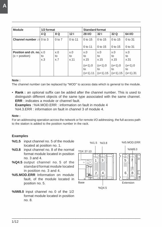
Examples
%I1.5 input channel no. 5 of the modulelocated at position no. 1.
%I3.8 input channel no. 8 of the normalformat module located in positionno. 3 and 4.
%Q4.5 output channel no. 5 of thestandard format module locatedin position no. 3 and 4.
%I5.MOD.ERR Information on modulefault, of the module located inposition no. 5.
%IW8.0 input channel no. 0 of the 1/2format module located in positionno. 8.
6 8
5 7
Base Extension
%IW8.0TSX 37-10
%Q4.5
%I5.MOD.ERR%I3.8%I1.5
2
1
4
3
PL7 general information 1
___________________________________________________________________________1/13
A
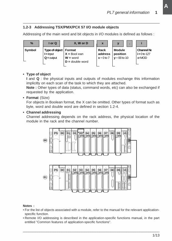
1.2-3 Addressing TSX/PMX/PCX 57 I/O module objects
Addressing of the main word and bit objects in I/O modules is defined as follows :
• Type of objectI and Q : the physical inputs and outputs of modules exchange this informationimplicitly on each scan of the task to which they are attached.Note : Other types of data (status, command words, etc) can also be exchanged ifrequested by the application.
• Format (Size)For objects in Boolean format, the X can be omitted. Other types of format such asbyte, word and double word are defined in section 1.2-4.
• Channel addressingChannel addressing depends on the rack address, the physical location of themodule in the rack and the channel number.
Notes :• For the list of objects associated with a module, refer to the manual for the relevant application-
specific function.• Remote I/O addressing is described in the application-specific functions manual, in the part
entitled "Common features of application-specific functions".
PS 00 01 02 03 04 05 06 07 08 09 10
PS 00 01 02 03 04 05 06 07 08 09 10
00
01
% I or Q X, W or D y . i
Symbol Type of objectI = inputQ =output
FormatX = Bool eanW = wordD = double word
Modulepositiony= 00 to 10
Channel Noi =0 to 127or MOD
x
Rackaddressx= 0 to 7
1/14___________________________________________________________________________
A
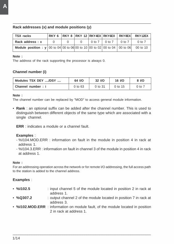
Rack addresses (x) and module positions (y)
TSX racks RKY 6 RKY 8 RKY 12 RKY 4EX RKY 6EX RKY 8EX RKY 12EX
Rack address : x 0 0 0 0 to 7 0 to 7 0 to 7 0 to 7
Module position : y 00 to 04 00 to 06 00 to 10 00 to 02 00 to 04 00 to 06 00 to 10
Note :The address of the rack supporting the processor is always 0.
Channel number (i)
Modules TSX DEY ..../DSY .... 64 I/O 32 I/O 16 I/O 8 I/O
Channel number : i 0 to 63 0 to 31 0 to 15 0 to 7
Note :The channel number can be replaced by "MOD" to access general module information.
• Rank : an optional suffix can be added after the channel number. This is used todistinguish between different objects of the same type which are associated with asingle channel.
ERR : indicates a module or a channel fault.
Examples :- %I104.MOD.ERR : information on fault in the module in position 4 in rack at
address 1.- %I104.3.ERR : information on fault in channel 3 of the module in position 4 in rack
at address 1.
Note :For an addressing operation across the network or for remote I/O addressing, the full access pathto the station is added to the channel address.
Examples :
• %I102.5 : input channel 5 of the module located in position 2 in rack ataddress 1.
• %Q307.2 : output channel 2 of the module located in position 7 in rack ataddress 3.
• %I102.MOD.ERR : information on module fault, of the module located in position2 in rack at address 1.
PL7 general information 1
___________________________________________________________________________1/15
A
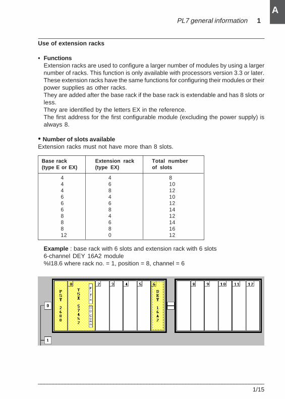
Use of extension racks
• FunctionsExtension racks are used to configure a larger number of modules by using a largernumber of racks. This function is only available with processors version 3.3 or later.These extension racks have the same functions for configuring their modules or theirpower supplies as other racks.They are added after the base rack if the base rack is extendable and has 8 slots orless.They are identified by the letters EX in the reference.The first address for the first configurable module (excluding the power supply) isalways 8.
• Number of slots availableExtension racks must not have more than 8 slots.
Base rack Extension rack Total number (type E or EX) (type EX) of slots
4 4 84 6 104 8 126 4 106 6 126 8 148 4 128 6 148 8 1612 0 12
Example : base rack with 6 slots and extension rack with 6 slots6-channel DEY 16A2 module%I18.6 where rack no. = 1, position = 8, channel = 6
1/16___________________________________________________________________________
A
0 1 1 1
15 14 13 12
0 1 1 1
11 10 9 8
0 0 1 1
7 6 5 4
0 1 0 0
3 2 1 0
Least significantMost significant
Bit rank
16-bit format
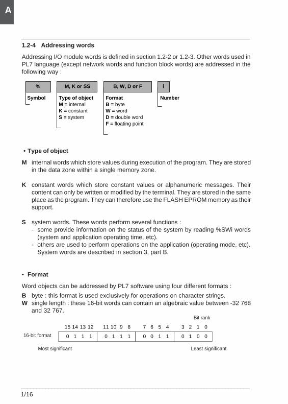
1.2-4 Addressing words
Addressing I/O module words is defined in section 1.2-2 or 1.2-3. Other words used inPL7 language (except network words and function block words) are addressed in thefollowing way :
% B, W, D or F
Symbol FormatB = byteW = wordD = double wordF = floating point
Number
M, K or SS
Type of objectM = internalK = constantS = system
i
• Type of object
M internal words which store values during execution of the program. They are storedin the data zone within a single memory zone.
K constant words which store constant values or alphanumeric messages. Theircontent can only be written or modified by the terminal. They are stored in the sameplace as the program. They can therefore use the FLASH EPROM memory as theirsupport.
S system words. These words perform several functions :- some provide information on the status of the system by reading %SWi words
(system and application operating time, etc).- others are used to perform operations on the application (operating mode, etc).
System words are described in section 3, part B.
• Format
Word objects can be addressed by PL7 software using four different formats :
B byte : this format is used exclusively for operations on character strings.W single length : these 16-bit words can contain an algebraic value between -32 768
and 32 767.
PL7 general information 1
___________________________________________________________________________1/17
A
0 1 0 1
15 14 13 12
0 0 1 1
11 10 9 8
1 1 1 1
7 6 5 4
0 1 1 1
3 2 1 0
0 0 1 1 0 1 1 0 0 1 0 1 0 0 1 0
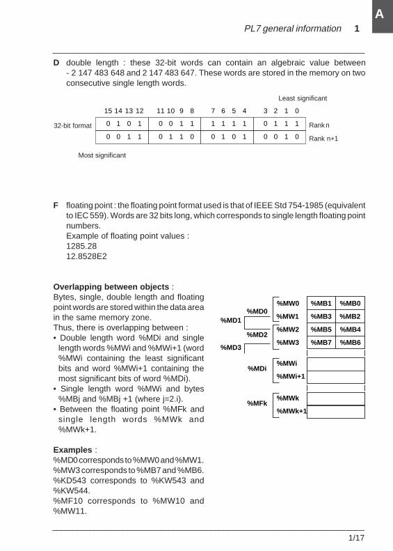
D double length : these 32-bit words can contain an algebraic value between- 2 147 483 648 and 2 147 483 647. These words are stored in the memory on twoconsecutive single length words.
F floating point : the floating point format used is that of IEEE Std 754-1985 (equivalentto IEC 559). Words are 32 bits long, which corresponds to single length floating pointnumbers.Example of floating point values :1285.2812.8528E2
Overlapping between objects :Bytes, single, double length and floatingpoint words are stored within the data areain the same memory zone.Thus, there is overlapping between :• Double length word %MDi and single
length words %MWi and %MWi+1 (word%MWi containing the least significantbits and word %MWi+1 containing themost significant bits of word %MDi).
• Single length word %MWi and bytes%MBj and %MBj +1 (where j=2.i).
• Between the floating point %MFk andsingle length words %MWk and%MWk+1.
Examples :%MD0 corresponds to %MW0 and %MW1.%MW3 corresponds to %MB7 and %MB6.%KD543 corresponds to %KW543 and%KW544.%MF10 corresponds to %MW10 and%MW11.
32-bit format
Least significant
Rank n
Rank n+1
Most significant
%MB1 %MB0
%MB3 %MB2
%MB5
%MB7
%MB4
%MB6
%MW0
%MW1
%MW2
%MW3
%MD0
%MD2
%MD1
%MD3
%MWi
%MWi+1%MDi
%MWk
%MWk+1%MFk
1/18___________________________________________________________________________
A
Type Syntax
WORD :X j
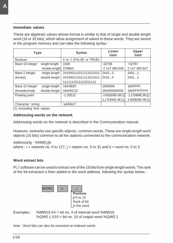
Immediate values
These are algebraic values whose format is similar to that of single and double lengthword (16 or 32 bits), which allow assignment of values to these words. They are storedin the program memory and can take the following syntax :
Lower Upperlimit limit
Boolean 0 or 1 (FALSE or TRUE)Base 10 integer single length 1506 -32768 +32767
double length 578963 -2 147 483 648 2 147 483 647Base 2 integer single length 2#1000111011111011011 2#10...0 2#01...1(binary) double length 2#1000111011111011011 2#10...0 2#01...1
1111111011111011111Base 10 integer single length 16#AB20 16#0000 16#FFFF(hexadecimal) double length 16#5AC10 16#000000000 16#FFFFFFFFFloating point -1.32E12 -3.402824E+38 (1) -1.175494E-38 (1)
1.175494E-38 (1) 3.402824E+38 (1)Character string 'aAbBcC'
(1) excluding limit values
Addressing words on the network
Addressing words on the network is described in the Communication manual.
However, networks use specific objects : common words. These are single length wordobjects (16 bits) common to all the stations connected to the communication network.
Addressing : %NW{i.j}kwhere : i = network no. 0 to 127, j = station no. 0 to 31 and k = word no. 0 to 3
Word extract bits
PL7 software can be used to extract one of the 16 bits from single length words. The rankof the bit extracted is then added to the word address, following the syntax below :
Examples : %MW10:X4 = bit no. 4 of internal word %MW10%QW5.1:X10 = bit no. 10 of output word %QW5.1
Note : Word bits can also be extracted on indexed words.
Positionj=0 to 15Rank of bitin the word
PL7 general information 1
___________________________________________________________________________1/19
A
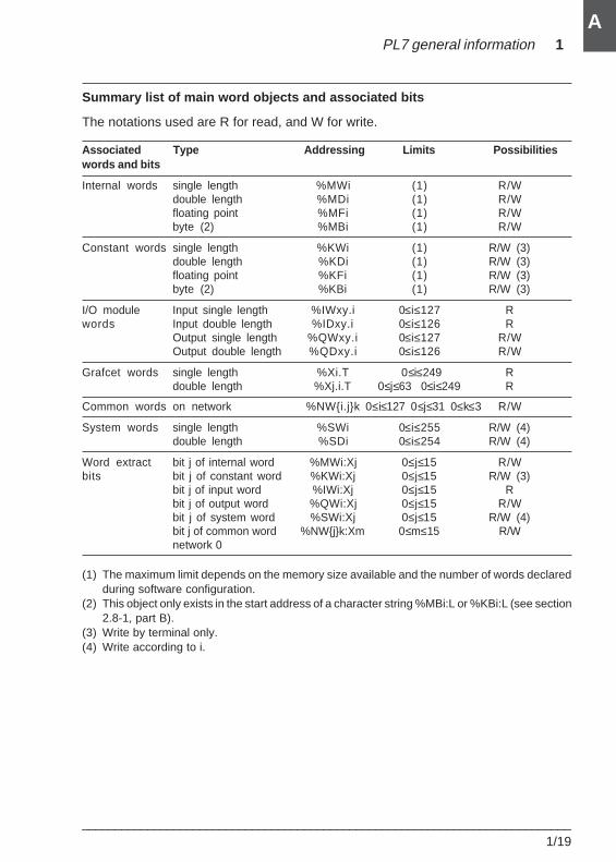
Summary list of main word objects and associated bits
The notations used are R for read, and W for write.
Associated Type Addressing Limits Possibilitieswords and bits
Internal words single length %MWi (1) R/Wdouble length %MDi (1) R/Wfloating point %MFi (1) R/Wbyte (2) %MBi (1) R/W
Constant words single length %KWi (1) R/W (3)double length %KDi (1) R/W (3)floating point %KFi (1) R/W (3)byte (2) %KBi (1) R/W (3)
I/O module Input single length %IWxy.i 0≤i≤127 Rwords Input double length %IDxy.i 0≤i≤126 R
Output single length %QWxy.i 0≤i≤127 R/WOutput double length %QDxy.i 0≤i≤126 R/W
Grafcet words single length %Xi.T 0≤i≤249 Rdouble length %Xj.i.T 0≤j≤63 0≤i≤249 R
Common words on network %NW{i.j}k 0≤i≤127 0≤j≤31 0≤k≤3 R/W
System words single length %SWi 0≤i≤255 R/W (4)double length %SDi 0≤i≤254 R/W (4)
Word extract bit j of internal word %MWi:Xj 0≤j≤15 R/Wbits bit j of constant word %KWi:Xj 0≤j≤15 R/W (3)
bit j of input word %IWi:Xj 0≤j≤15 Rbit j of output word %QWi:Xj 0≤j≤15 R/Wbit j of system word %SWi:Xj 0≤j≤15 R/W (4)bit j of common word %NW{j}k:Xm 0≤m≤15 R/Wnetwork 0
(1) The maximum limit depends on the memory size available and the number of words declaredduring software configuration.
(2) This object only exists in the start address of a character string %MBi:L or %KBi:L (see section2.8-1, part B).
(3) Write by terminal only.(4) Write according to i.
1/20___________________________________________________________________________
A
R
S
CU
CD F
D
E
%Ci
C.P : 9999
MODIF : Y
Up/down counter block
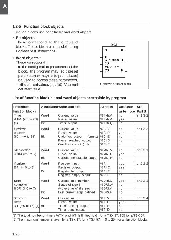
1.2-5 Function block objects
Function blocks use specific bit and word objects.
• Bit objects :These correspond to the outputs ofblocks. These bits are accessible usingBoolean test instructions.
• Word objects :These correspond :- to the configuration parameters of the
block. The program may (eg : presetparameter) or may not (eg : time base)be used to access these parameters,
- to the current values (eg : %Ci.V currentcounter value).
List of function block bit and word objects accessible by program
Predefined Associated words and bits Address Access in See function blocks write mode Part B Timer Word Current value %TMi.V no sn1.3-2 %TMi (i=0 to 63) Preset value %TMi.P yes (1) Bit Timer output %TMi.Q no
Up/down Word Current value %Ci.V no sn1.3-3 counter Preset value %Ci.P yes %Ci (i=0 to 31) Bit Underflow output (empty) %Ci.E no
Preset reached output %Ci.D noOverflow output (full) %Ci.F no
Monostable Word Current value %MNi.V no sn2.2-1 %MNi (i=0 to 7) Preset value %MNi.P yes
Bit Current monostable output %MNi.R no
Register Word Register input %Ri.I yes sn2.2-2 %Ri (i= 0 to 3) Register output %Ri.O yes
Bit Register full output %Ri.F noRegister empty output %Ri.E no
Drum Word Current step number %DRi.S yes sn2.2-3 controller Status of step j %DRi.Wj no %DRi (i=0 to 7) Active time of the step %DRi.V no
Bit Last current step defined %DRi.F no
Series 7 Word Current value %Ti.V no sn2.2-4 timer Preset value %Ti.P yes %T (i=0 to 63) (1) Bit Timer running output %Ti.R no
Timer done output %Ti.D no
(1) The total number of timers %TMi and %Ti is limited to 64 for a TSX 37, 255 for a TSX 57.(2) The maximum number is given for a TSX 37, for a TSX 57 i = 0 to 254 for all function blocks.
PL7 general information 1
___________________________________________________________________________1/21
A
16 bits%KW10
%KW14
8 bits%MB10
%MB14
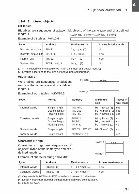
1.2-6 Structured objects
Bit tables
Bit tables are sequences of adjacent bit objects of the same type and of a definedlength, L.
Example of bit tables : %M10:6 nc by
Type Address Maximum size Access in write mode
Discrete input bits %Ix.i:L 1 < L < m (1) No
Discrete output bits %Qx.i:L 1 < L <m (1) Yes
Internal bits %Mi:L i+L < n (2) Yes
Grafcet bits %Xi:L, %Xj.i:L i+L < n (2) No
(1) m = modularity of the module (eg : 8 for an 8 input or 8 output module),(2) n varies according to the size defined during configuration.
Word tables
Word tables are sequences of adjacentwords of the same type and of a definedlength, L.
Example of word tables : %KW10:5
Type Format Address Maximum Access insize write mode
Internal words Single length %MWi:L i+L < Nmax (2) YesDouble length %MDi:L i+L <Nmax-1 (2) YesFloating point %MFi:L i+L < Nmax-1 (2)Yes
Constant words Single length %KWi:L i+L < Nmax (2) NoDouble length %KDi:L i+L< Nmax-1 (2) NoFloating point %KFi:L i+L <Nmax-1 (2) No
Grafcet words Single length %Xi.T:L, %Xj.i.T:L i+L<Nmax-1 (2) No
System words Single length %SW50:4 (3) Yes
Character strings
Character strings are sequences ofadjacent bytes of the same type and of adefined length, L.
Example of character string : %MB10:5
Type Address Maximum size Access in write mode
Internal words %MBi:L (5) 1-i+L< Nmax (4) Yes
Constant words %KBi:L (5) 1-i+L< Nmax (4) Yes
(3) Only words %SW50 to %SW53 can be addressed in table form.(4) Nmax = maximum number defined during software configuration.(5) i must be even.
%M10 %M11 %M12 %M13 %M14 %M15
1/22___________________________________________________________________________
A
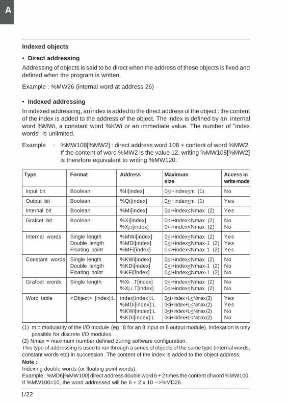
Indexed objects
• Direct addressing
Addressing of objects is said to be direct when the address of these objects is fixed anddefined when the program is written.
Example : %MW26 (internal word at address 26)
• Indexed addressing
In indexed addressing, an index is added to the direct address of the object : the contentof the index is added to the address of the object. The index is defined by an internalword %MWi, a constant word %KWi or an immediate value. The number of "indexwords" is unlimited.
Example : %MW108[%MW2] : direct address word 108 + content of word %MW2.If the content of word %MW2 is the value 12, writing %MW108[%MW2]is therefore equivalent to writing %MW120.
Type Format Address Maximum Access insize write mode
Input bit Boolean %Ii[index] 0<i+index<m (1) No
Output bit Boolean %Qi[index] 0<i+index<m (1) Yes
Internal bit Boolean %Mi[index] 0<i+index<Nmax (2) Yes
Grafcet bit Boolean %Xi[index] 0<i+index<Nmax (2) No%Xj.i[index] 0<i+index<Nmax (2) No
Internal words Single length %MWi[index] 0<i+index<Nmax (2) YesDouble length %MDi[index] 0<i+index<Nmax-1 (2) YesFloating point %MFi[index] 0<i+index<Nmax-1 (2) Yes
Constant words Single length %KWi[index] 0<i+index<Nmax (2) NoDouble length %KDi[index] 0<i+index<Nmax-1 (2) NoFloating point %KFi[index] 0<i+index<Nmax-1 (2) No
Grafcet words Single length %Xi .T[index] 0<i+index<Nmax (2) No%Xj.i.T[index] 0<i+index<Nmax (2) No
Word table <Object> [index]:L index[index]:L 0<i+index+L<Nmax (2) Yes%MDi[index]:L 0<i+index+L<Nmax (2) Yes%KWi[index]:L 0<i+index+L<Nmax (2) No%KDi[index]:L 0<i+index+L<Nmax (2) No
(1) m = modularity of the I/O module (eg : 8 for an 8 input or 8 output module). Indexation is onlypossible for discrete I/O modules.
(2) Nmax = maximum number defined during software configuration.This type of addressing is used to run through a series of objects of the same type (internal words,constant words etc) in succession. The content of the index is added to the object address.Note :Indexing double words (or floating point words).Example : %MD6[%MW100] direct address double word 6 + 2 times the content of word %MW100.If %MW100=10, the word addressed will be 6 + 2 x 10 -->%MD26.
PL7 general information 1
___________________________________________________________________________1/23
A
• Index overrun, system bit %S20
Index overrun occurs as soon as the address of an indexed object exceeds the limitsof the zone including this same type of object, that is, when :• object address + index content is lower than the value zero.• object address + index content is higher than the maximum limit configured (see table
on the previous page).
In the event of index overrun, the system sets system bit %S20 to 1 and the object isassigned an index value of 0.
Monitoring of overrun is the responsibility of the user : bit %S20 must be read by the userprogram for any processing. Resetting it is the responsibility of the user.
%S20 (initial state = 0) :• on index overrun : set to 1 by the system,• overrun acknowledgment : set to 0 by the user after modification of the index.
1.2-7 Grafcet objects
Bit objects
The user has the following bit objects :• %Xi associated with the steps which enable him to identify the status of step i of the
main chart.• %XMj associated with the macro-steps which enable him to identify the status of
Grafcet macro-step j.• %Xj.i associated with step i of macro-step j which enable him to identify the status of
Grafcet step i of macro-step j.• %Xj.IN or %Xj.OUT associated with the input or output step of the macro-step.These bits are set to 1 when the step or macro-step is active, and 0 when it is inactive.
Word objects
One word is associated with each step : %Xi.T, %Xj.i.T, %Xj.IN.T or %Xj.OUT.T. Itindicates the activity time of Grafcet step i. It is incremented every 100ms and takes avalue between 0 and 9999.
1.2-8 DFB objects
The DFB output parameters and public variables can be accessed by the program.These objects are Boolean, numerical, or table objects (see section 6).These objects are purely symbolic and are defined by the following syntax :DFB_name.Parameter_name, where DFB_name is the name given to the DFB used(32 characters maximum) and Parameter_name is the name given to the outputparameter or the public variable (8 characters maximum).
1/24___________________________________________________________________________
A
1.2-9 Symbolization
Symbols
A symbol is a string of up to 32 alphanumeric characters, of which the first character isalphabetical. A symbol starts with a capital letter, followed by letters in lower case (forexample : the symbol Burner_1). When it is entered, the symbol can be written in upperor lower case (for example : BURNER_1). The software automatically puts the symbolinto its correct format.
The following characters can therefore be used :• upper case alphabetical :
"A to Z" and accented letters "ÀÁÂÃÄÅÆÇÈÉÊËÌÍÎÏDÑÒÓÓÕÖØÙÚÛÜYp"or lower case alphabetical :" a to z", and accented letters : àáâãäåæçèéêëìíîïðñòóôõöØùúûüypßÿ
• numerical : digits 0 to 9 (they cannot be placed at the start of the symbol).• the character "_" (this cannot be placed either at the beginning or end of the symbol).
A number of words are reserved by the language and cannot be used as symbols. Seefull list in section 5 part B.
The symbols are defined and associated with language objects by the variables editor(see section 5, part D). A comment of 508 characters can be associated with eachsymbol. The symbols and their comments are saved to the terminal disk and not in thePLC.
Objects which can be symbolized
All PL7 objects can be symbolized except table type structured objects and indexedobjects, but if the base object or the index is symbolized, the symbol is used in thestructured object.
Examples :• if word %MW0 has "Temperature" as its symbol, the word table %MW0:12 is
symbolized by "Temperature:12"• if word %MW10 has "Oven_1" as its symbol, the indexed word %MW0[%MW10] is
symbolized by "Temperature[oven_1]".
Word extract bit objects and function block bits or words can be symbolized, but if theyare not symbolized, they can take on the symbol of the base object.Examples :• if word %MW0 has " Pump_status" as its symbol and if the word extract bit %MW0:X1
is not symbolized, it takes on the symbol of the word. %MW0:X1 has as its symbol,"Pump_status:X1".
• if function block %TM0 has "Oven1_timer" as its symbol and if output %TM0.D is notsymbolized, it takes on a symbol of the block. %TM0.D has as its symbol,"Oven_timer.D".
PL7 general information 1
___________________________________________________________________________1/25
A
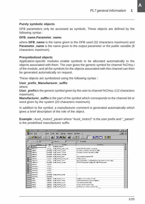
Purely symbolic objects
DFB parameters only be accessed as symbols. These objects are defined by thefollowing syntax :
DFB_name.Parameter_name.
where DFB_name is the name given to the DFB used (32 characters maximum) andParameter_name is the name given to the output parameter or the public variable (8characters maximum).
Presymbolized objectsApplication-specific modules enable symbols to be allocated automatically to theobjects associated with them. The user gives the generic symbol for channel %CHxy.iof the module, and all the symbols for the objects associated with this channel can thenbe generated automatically on request.
These objects are symbolized using the following syntax :
User_prefix_Manufacturer_suffixwhereUser_prefix is the generic symbol given by the user to channel %CHxy.i (12 charactersmaximum),Manufacturer_suffix is the part of the symbol which corresponds to the channel bit orword given by the system (20 characters maximum).
In addition to the symbol, a manufacturer comment is generated automatically whichgives a brief description of the role of the object.
Example : Auxil_motor2_param where "Auxil_motor2" is the user prefix and "_param"is the predefined manufacturer suffix.
1/26___________________________________________________________________________
A
1.3 User memory
1.3-1 General
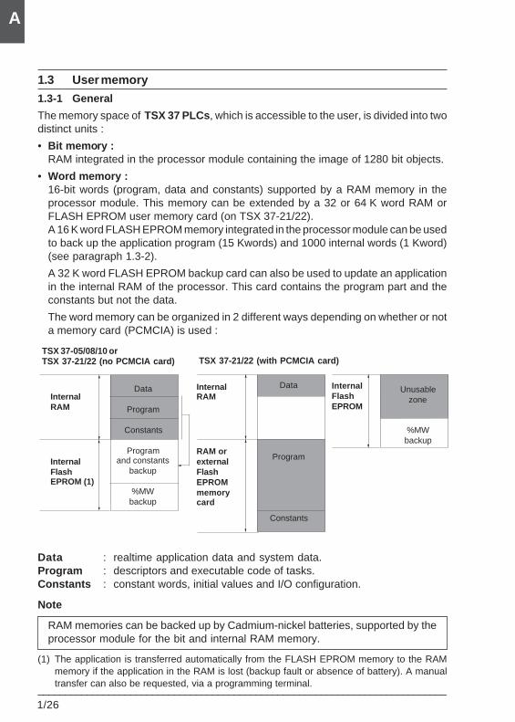
The memory space of TSX 37 PLCs , which is accessible to the user, is divided into twodistinct units :
• Bit memory :RAM integrated in the processor module containing the image of 1280 bit objects.
• Word memory :16-bit words (program, data and constants) supported by a RAM memory in theprocessor module. This memory can be extended by a 32 or 64 K word RAM orFLASH EPROM user memory card (on TSX 37-21/22).A 16 K word FLASH EPROM memory integrated in the processor module can be usedto back up the application program (15 Kwords) and 1000 internal words (1 Kword)(see paragraph 1.3-2).
A 32 K word FLASH EPROM backup card can also be used to update an applicationin the internal RAM of the processor. This card contains the program part and theconstants but not the data.
The word memory can be organized in 2 different ways depending on whether or nota memory card (PCMCIA) is used :
Data : realtime application data and system data.Program : descriptors and executable code of tasks.Constants : constant words, initial values and I/O configuration.
Note
RAM memories can be backed up by Cadmium-nickel batteries, supported by theprocessor module for the bit and internal RAM memory.
(1) The application is transferred automatically from the FLASH EPROM memory to the RAMmemory if the application in the RAM is lost (backup fault or absence of battery). A manualtransfer can also be requested, via a programming terminal.
TSX 37-05/08/10 orTSX 37-21/22 (no PCMCIA card)
InternalRAM
InternalFlashEPROM (1)
Data
Program
Constants
InternalRAM
RAM orexternalFlashEPROMmemorycard
TSX 37-21/22 (with PCMCIA card)
Unusablezone
%MWbackup
InternalFlashEPROM
Data
Program
Constants
Programand constants
backup
%MWbackup
PL7 general information 1
___________________________________________________________________________1/27
A
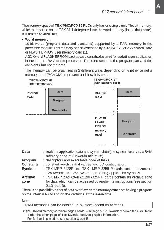
The memory space of TSX/PMX/PCX 57 PLCs only has one single unit. The bit memory,which is separate on the TSX 37, is integrated into the word memory (in the data zone).It is limited to 4096 bits.
• Word memory :16-bit words (program, data and constants) supported by a RAM memory in theprocessor module. This memory can be extended by a 32, 64, 128 or 256 K word RAMor FLASH EPROM user memory card (1).A 32 K word FLASH EPROM backup card can also be used for updating an applicationin the internal RAM of the processor. This card contains the program part and theconstants but not the data.
The memory can be organized in 2 different ways depending on whether or not amemory card (PCMCIA) is present and how it is used :
Data : realtime application data and system data (the system reserves a RAMmemory zone of 5 Kwords minimum).
Program : descriptors and executable code of tasks.Constants : constant words, initial values and I/O configuration.Symbols : TSX MRP 2128P and TSX MRP 3256 P cards contain a zone of
128 Kwords and 256 Kwords for storing application symbols.Archive : TSX MRP 232P/264P/2128P/3256 P cards contain an archive zonezone for data which can be accessed by read/write instructions (see section
2.13, part B).There is no possibility either of data overflow on the memory card or of having a programon the internal RAM and on the cartridge at the same time.
NoteRAM memories can be backed up by nickel-cadmium batteries.
TSX/PMX/PCX 57(no memory card)
TSX/PMX/PCX 57(with memory card)
InternalRAM
Data Data
Program
Program
Constants
Constants
InternalRAM
RAM orFLASHEPROMmemorycard
(1)256 Kword memory cards are paged cards. One page of 128 Kwords receives the executablecode, the other page of 128 Kwords receives graphic information.For further information, see section 8 part B.
1/28___________________________________________________________________________
A
1.3-2 Saving / retrieving internal words %MWi
Saving internal words %MWiIn order to save adjustment data in the event of a power outage, when the processorbattery is faulty or missing, TSX 37 PLCs can copy 1000 internal words (%MW)maximum to the internal Flash EPROM memory. This backup zone can be used at alltimes, even if the PLC is fitted with a PCMCIA memory card (TSX 37-21/22).To save internal words to the Flash EPROM, the application must be stopped . It istriggered according to the choice made during configuration :
• by setting the discrete input %I1.9 to 1,• from an adjustment panel, by setting bit 0 of %SW96 to 1.
The value of system word %SW97 defines the number of %MWi to be saved (1000maximum).
At the end of the backup, the display block displays OK or NOK depending on the resultof the operation.
The internal words %MWi are always saved when the application program issaved .If system word %SW97 is initialized to 0, only the application program contained in theinternal RAM is transferred to the Flash EPROM (equivalent to a Backup program).Warning : any saved %MWi are still erased.
Retrieving internal words %MWiSaved %MWi are transferred from the internal Flash EPROM memory to the RAMmemory on a cold start caused by :• loss of the internal RAM contents. In this case, if the application program backup is
valid, this is also transferred to the internal RAM (TSX 37-10 or TSX 37-20 withoutPCMCIA application cartridge),
• pressing the RESET button, on the front panel of the PLC,• setting bit %S0 to 1, in adjust mode,• clicking on the "Cold start" button in the PL7 processor debug screen,• transferring a program to the PLC (via terminal port, FIPWAY, etc),• plugging in a PCMCIA application cartridge.
For the saved %MW to be retrieved to the internal RAM, the "Reset %MWi on cold start"box must not be checked in the processor configuration screen.For further information, refer to part A of the TSX Micro installation manual.
PL7 general information 1
___________________________________________________________________________1/29
A
1.3-3 Bit memory
Composition
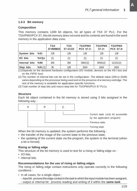
This memory contains 1280 bit objects, for all types of TSX 37 PLC. For theTSX/PMX/PCX 57, this bit memory does not exist and its contents are found in the wordmemory in the application data zone.
TSX TSX TSX/PMX TSX/PMX TSX/PMX 37-05/08/10 37-21/22 PCX 57-1• 57-2• PCX 57-3•
System bits %SI 128 128 128 128 128
I/O bits %I/Qx (1) (1) (1) (1) (1)
Internal bits %Mi 256 256 3962 (2) 8056 (2) 12152 (2)
Step bits %Xi (3) 96 128 1024 1024 1024(1)Depends on the declared hardware configuration (I/O module, devices on the AS-i bus and
on the FIPIO bus)(2) The number of internal bits can be set in the configuration. The default value (256 to 2048)
varies depending on the processor being used and on the presence of a memory cartridge. Therest of the memory is available for application-specific functions.
(3) Total number of step bits and macro-step bits for TSX/PMX/PCX 57 PLCs.
StructureEach bit object contained in the bit memory is stored using 3 bits assigned in thefollowing way :
When the bit memory is updated, the system performs the following :• the transfer of the image of the current state to the previous state,• the updating of the current state via the program, the system or the terminal (when
a bit is forced).
Rising or falling edgeThis structure of the bit memory is used to test for a rising or falling edge on :• I/O bits,• internal bits.
Recommendations for the use of rising or falling edgesThe rising or falling edge contact instructions only operate correctly in the followingconditions :
• In all cases, for a single object :- input bit : process the edge contact in the task to which the input module has been assigned,- output or internal bit : process reading and writing of it within the same task .
F P C
Current state (only bit accessible
by the application program)
Previous state
Forcing state
1/30___________________________________________________________________________
A
• Write the coil of an object once only when an edge contact of this object is used ina program.
• Do not perform a SET or RESET on an object where the edge is tested, because evenif the result of the equation conditioning the SET/RESET equals 0, the SET/RESETaction is not performed, but the object log is updated (loss of the edge).
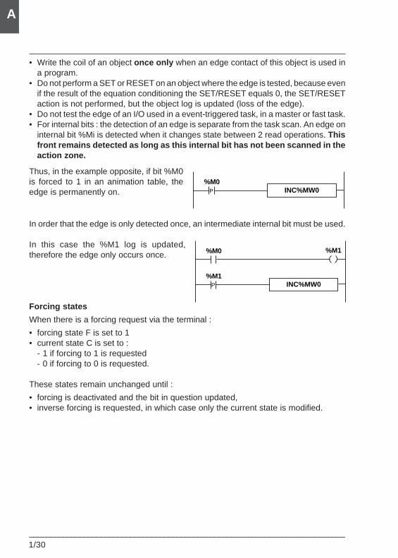
• Do not test the edge of an I/O used in a event-triggered task, in a master or fast task.• For internal bits : the detection of an edge is separate from the task scan. An edge on
internal bit %Mi is detected when it changes state between 2 read operations. Thisfront remains detected as long as this internal bit has not been scanned in theaction zone.
Thus, in the example opposite, if bit %M0is forced to 1 in an animation table, theedge is permanently on.
In order that the edge is only detected once, an intermediate internal bit must be used.
In this case the %M1 log is updated,therefore the edge only occurs once.
Forcing states
When there is a forcing request via the terminal :
• forcing state F is set to 1• current state C is set to :
- 1 if forcing to 1 is requested- 0 if forcing to 0 is requested.
These states remain unchanged until :
• forcing is deactivated and the bit in question updated,• inverse forcing is requested, in which case only the current state is modified.
INC%MW0P
%M0
INC%MW0P
%M1
%M1%M0
PL7 general information 1
___________________________________________________________________________1/31
A
1.3-4 Word memory
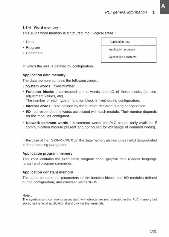
This 16-bit word memory is structured into 3 logical areas :
• Data
• Program
• Constants
of which the size is defined by configuration.
Application data memory
The data memory contains the following zones :
• System words : fixed number
• Function blocks : correspond to the words and I/O of these blocks (current,adjustment values, etc).The number of each type of function block is fixed during configuration.
• Internal words : size defined by the number declared during configuration.
• I/O : correspond to the words associated with each module. Their number dependson the modules configured.
• Network common words : 4 common words per PLC station (only available ifcommunication module present and configured for exchange of common words).
In the case of the TSX/PMX/PCX 57, the data memory also includes the bit data detailedin the preceding paragraph.
Application program memory
This zone contains the executable program code, graphic data (Ladder languagerungs) and program comments.
Application constant memory
This zone contains the parameters of the function blocks and I/O modules definedduring configuration, and constant words %KW.
Note :The symbols and comments associated with objects are not recorded in the PLC memory butstored in the local application (hard disk on the terminal).
Application program
Application constants
Application data
1/32___________________________________________________________________________
A
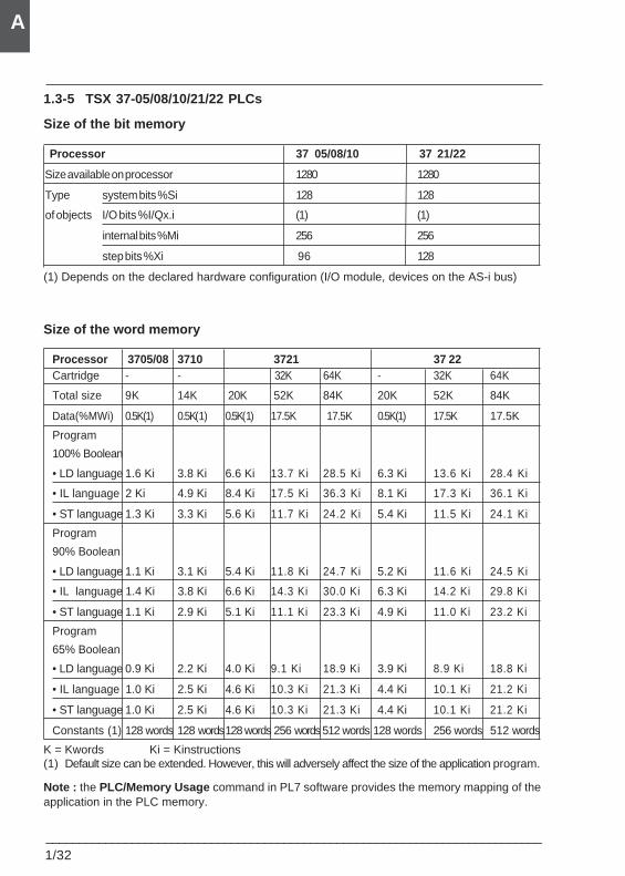
1.3-5 TSX 37-05/08/10/21/22 PLCs
Size of the bit memory
Processor 37 05/08/10 37 21/22
Size available on processor 1280 1280
Type system bits %Si 128 128
of objects I/O bits %I/Qx.i (1) (1)
internal bits %Mi 256 256
step bits %Xi 96 128
(1) Depends on the declared hardware configuration (I/O module, devices on the AS-i bus)
Size of the word memory
Processor 3705/08 3710 3721 37 22Cartridge - - 32K 64K - 32K 64K
Total size 9K 14K 20K 52K 84K 20K 52K 84K
Data(%MWi) 0.5K(1) 0.5K(1) 0.5K(1) 17.5K 17.5K 0.5K(1) 17.5K 17.5K
Program
100% Boolean
• LD language 1.6 Ki 3.8 Ki 6.6 Ki 13.7 Ki 28.5 Ki 6.3 Ki 13.6 Ki 28.4 Ki
• IL language 2 Ki 4.9 Ki 8.4 Ki 17.5 Ki 36.3 Ki 8.1 Ki 17.3 Ki 36.1 Ki
• ST language 1.3 Ki 3.3 Ki 5.6 Ki 11.7 Ki 24.2 Ki 5.4 Ki 11.5 Ki 24.1 Ki
Program
90% Boolean
• LD language 1.1 Ki 3.1 Ki 5.4 Ki 11.8 Ki 24.7 Ki 5.2 Ki 11.6 Ki 24.5 Ki
• IL language 1.4 Ki 3.8 Ki 6.6 Ki 14.3 Ki 30.0 Ki 6.3 Ki 14.2 Ki 29.8 Ki
• ST language 1.1 Ki 2.9 Ki 5.1 Ki 11.1 Ki 23.3 Ki 4.9 Ki 11.0 Ki 23.2 Ki
Program
65% Boolean
• LD language 0.9 Ki 2.2 Ki 4.0 Ki 9.1 Ki 18.9 Ki 3.9 Ki 8.9 Ki 18.8 Ki
• IL language 1.0 Ki 2.5 Ki 4.6 Ki 10.3 Ki 21.3 Ki 4.4 Ki 10.1 Ki 21.2 Ki
• ST language 1.0 Ki 2.5 Ki 4.6 Ki 10.3 Ki 21.3 Ki 4.4 Ki 10.1 Ki 21.2 Ki
Constants (1) 128 words 128 words128 words 256 words 512 words 128 words 256 words 512 words
K = Kwords Ki = Kinstructions(1) Default size can be extended. However, this will adversely affect the size of the application program.
Note : the PLC/Memory Usage command in PL7 software provides the memory mapping of theapplication in the PLC memory.
PL7 general information 1
___________________________________________________________________________1/33
A
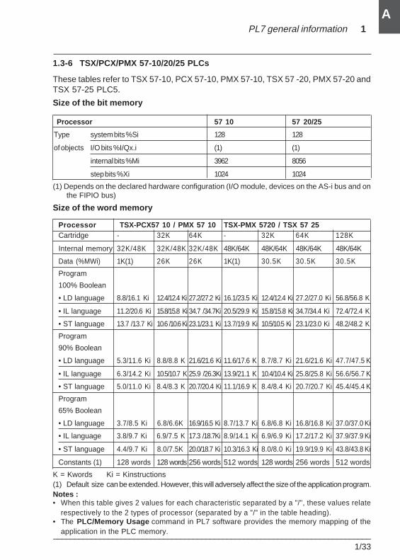
1.3-6 TSX/PCX/PMX 57-10/20/25 PLCs
These tables refer to TSX 57-10, PCX 57-10, PMX 57-10, TSX 57 -20, PMX 57-20 andTSX 57-25 PLC5.
Size of the bit memory
Processor 57 10 57 20/25
Type system bits %Si 128 128
of objects I/O bits %I/Qx.i (1) (1)
internal bits %Mi 3962 8056
step bits %Xi 1024 1024
(1) Depends on the declared hardware configuration (I/O module, devices on the AS-i bus and onthe FIPIO bus)
Size of the word memory
Processor TSX-PCX57 10 / PMX 57 10 TSX-PMX 5720 / TSX 57 25Cartridge - 32K 64K - 32K 64K 128K
Internal memory 32K/48K 32K/48K 32K/48K 48K/64K 48K/64K 48K/64K 48K/64K
Data (%MWi) 1K(1) 26K 26K 1K(1) 30.5K 30.5K 30.5K
Program
100% Boolean
• LD language 8.8/16.1 Ki 12.4/12.4 Ki 27.2/27.2 Ki 16.1/23.5 Ki 12.4/12.4 Ki 27.2/27.0 Ki 56.8/56.8 K
• IL language 11.2/20.6 Ki 15.8/15.8 Ki 34.7 /34.7Ki 20.5/29.9 Ki 15.8/15.8 Ki 34.7/34.4 Ki 72.4/72.4 K
• ST language 13.7 /13.7 Ki 10.6 /10.6 Ki 23.1/23.1 Ki 13.7/19.9 Ki 10.5/10.5 Ki 23.1/23.0 Ki 48.2/48.2 K
Program
90% Boolean
• LD language 5.3/11.6 Ki 8.8/8.8 K 21.6/21.6 Ki 11.6/17.6 K 8.7/8.7 Ki 21.6/21.6 Ki 47.7/47.5 K
• IL language 6.3/14.2 Ki 10.5/10.7 K 25.9 /26.3Ki 13.9/21.1 K 10.4/10.4 Ki 25.8/25.8 Ki 56.6/56.7 K
• ST language 5.0/11.0 Ki 8.4/8.3 K 20.7/20.4 Ki 11.1/16.9 K 8.4/8.4 Ki 20.7/20.7 Ki 45.4/45.4 K
Program
65% Boolean
• LD language 3.7/8.5 Ki 6.8/6.6K 16.9/16.5 Ki 8.7/13.7 Ki 6.8/6.8 Ki 16.8/16.8 Ki 37.0/37.0 Ki
• IL language 3.8/9.7 Ki 6.9/7.5 K 17.3 /18.7Ki 8.9/14.1 Ki 6.9/6.9 Ki 17.2/17.2 Ki 37.9/37.9 Ki
• ST language 4.4/9.7 Ki 8.0/7.5K 20.0/18.7 Ki 10.3/16.3 Ki 8.0/8.0 Ki 19.9/19.9 Ki 43.8/43.8 Ki
Constants (1) 128 words 128 words 256 words 512 words 128 words 256 words 512 words
K = Kwords Ki = Kinstructions(1) Default size can be extended. However, this will adversely affect the size of the application program.Notes :• When this table gives 2 values for each characteristic separated by a "/", these values relate
respectively to the 2 types of processor (separated by a "/" in the table heading).• The PLC/Memory Usage command in PL7 software provides the memory mapping of the
application in the PLC memory.
1/34___________________________________________________________________________
A
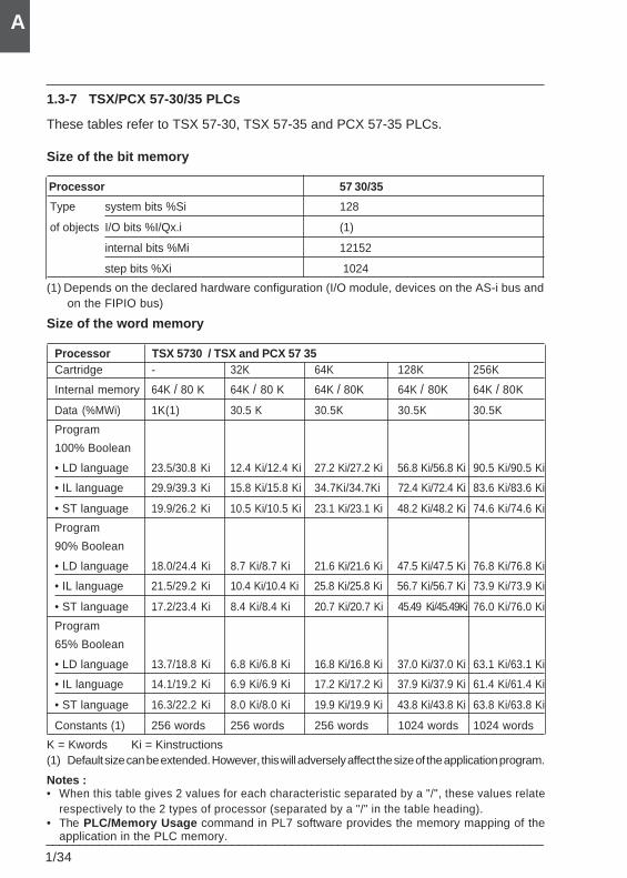
1.3-7 TSX/PCX 57-30/35 PLCs
These tables refer to TSX 57-30, TSX 57-35 and PCX 57-35 PLCs.
Size of the bit memory
Processor 57 30/35
Type system bits %Si 128
of objects I/O bits %I/Qx.i (1)
internal bits %Mi 12152
step bits %Xi 1024
(1) Depends on the declared hardware configuration (I/O module, devices on the AS-i bus andon the FIPIO bus)
Size of the word memory
Processor TSX 5730 / TSX and PCX 57 35Cartridge - 32K 64K 128K 256K
Internal memory 64K / 80 K 64K / 80 K 64K / 80K 64K / 80K 64K / 80K
Data (%MWi) 1K(1) 30.5 K 30.5K 30.5K 30.5K
Program
100% Boolean
• LD language 23.5/30.8 Ki 12.4 Ki/12.4 Ki 27.2 Ki/27.2 Ki 56.8 Ki/56.8 Ki 90.5 Ki/90.5 Ki
• IL language 29.9/39.3 Ki 15.8 Ki/15.8 Ki 34.7Ki/34.7Ki 72.4 Ki/72.4 Ki 83.6 Ki/83.6 Ki
• ST language 19.9/26.2 Ki 10.5 Ki/10.5 Ki 23.1 Ki/23.1 Ki 48.2 Ki/48.2 Ki 74.6 Ki/74.6 Ki
Program
90% Boolean
• LD language 18.0/24.4 Ki 8.7 Ki/8.7 Ki 21.6 Ki/21.6 Ki 47.5 Ki/47.5 Ki 76.8 Ki/76.8 Ki
• IL language 21.5/29.2 Ki 10.4 Ki/10.4 Ki 25.8 Ki/25.8 Ki 56.7 Ki/56.7 Ki 73.9 Ki/73.9 Ki
• ST language 17.2/23.4 Ki 8.4 Ki/8.4 Ki 20.7 Ki/20.7 Ki 45.49 Ki/45.49Ki 76.0 Ki/76.0 Ki
Program
65% Boolean
• LD language 13.7/18.8 Ki 6.8 Ki/6.8 Ki 16.8 Ki/16.8 Ki 37.0 Ki/37.0 Ki 63.1 Ki/63.1 Ki
• IL language 14.1/19.2 Ki 6.9 Ki/6.9 Ki 17.2 Ki/17.2 Ki 37.9 Ki/37.9 Ki 61.4 Ki/61.4 Ki
• ST language 16.3/22.2 Ki 8.0 Ki/8.0 Ki 19.9 Ki/19.9 Ki 43.8 Ki/43.8 Ki 63.8 Ki/63.8 Ki
Constants (1) 256 words 256 words 256 words 1024 words 1024 words
K = Kwords Ki = Kinstructions(1) Default size can be extended. However, this will adversely affect the size of the application program.
Notes :• When this table gives 2 values for each characteristic separated by a "/", these values relate
respectively to the 2 types of processor (separated by a "/" in the table heading).• The PLC/Memory Usage command in PL7 software provides the memory mapping of the
application in the PLC memory.
PL7 general information 1
___________________________________________________________________________1/35
A
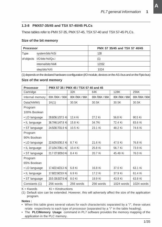
1.3-8 PMX57-35/45 and TSX 57-40/45 PLCs
These tables refer to PMX 57-35, PMX 57-45, TSX 57-40 and TSX 57-45 PLCs.
Size of the bit memory
Processor PMX 57 35/45 and TSX 57 40/45
Type system bits %Si 128
of objects I/O bits %I/Qx.i (1)
internal bits %Mi 12152
step bits %Xi 1024
(1) depends on the declared hardware cconfiguration (I/O module, devices on the AS-i bus and on the Fipio bus)
Size of the word memory
Processor PMX 57 35 / PMX 45 / TSX 57 40 and 45Cartridge - 32K 64K 128K 256K
Internal memory 80K /96K / 96K 80K /96K / 96K 80K /96K / 96K 80K /96K / 96K 80K /96K / 96K
Data(%MWi) 1K(1) 30.5K 30.5K 30.5K 30.5K
Program
100% Boolean
• LD language 28.8/36.1/37.5 Ki 12.4 Ki 27.2 Ki 56.8 Ki 90.5 Ki
• IL language 36.7/46.1/47.8 Ki 15.8 Ki 34.7Ki 72.4 Ki 83.6 Ki
• ST language 24.5/30.7/31.9 Ki 10.5 Ki 23.1 Ki 48.2 Ki 74.6 Ki
Program
90% Boolean
• LD language 22.6/29.0/30.3 Ki 8.7 Ki 21.6 Ki 47.5 Ki 76.8 Ki
• IL language 27.1/34.7/36.1 Ki 10.4 Ki 25.8 Ki 56.7 Ki 73.9 Ki
• ST language 21.7 /27.8/29.0 Ki 8.4 Ki 20.7 Ki 45.49 Ki 76.0 Ki
Program
65% Boolean
• LD language 17.4/22.4/23.3 Ki 6.8 Ki 16.8 Ki 37.0 Ki 63.1 Ki
• IL language 17.8/22.9/23.9 Ki 6.9 Ki 17.2 Ki 37.9 Ki 61.4 Ki
• ST language 20.5 /26.5/27.6 Ki 8.0 Ki 19.9 Ki 43.8 Ki 63.8 Ki
Constants (1) 256 words 256 words 256 words 1024 words 1024 words
K = Kwords Ki = Kinstructions(1) Default size can be extended. However, this will adversely affect the size of the application
program.
Notes :• When this table gives several values for each characteristic separated by a "/", these values
relate respectively to each type of processor (separated by a "/" in the table heading).• The PLC/Memory Usage command in PL7 software provides the memory mapping of the
application in the PLC memory.
1/36___________________________________________________________________________
A
1.4 Operating modes
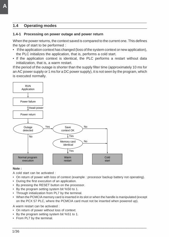
1.4-1 Processing on power outage and power return
When the power returns, the context saved is compared to the current one. This definesthe type of start to be performed :• If the application context has changed (loss of the system context or new application),
the PLC initializes the application, that is, performs a cold start.• If the application context is identical, the PLC performs a restart without data
initialization, that is, a warm restart.If the period of the outage is shorter than the supply filter time (approximately 10 ms foran AC power supply or 1 ms for a DC power supply), it is not seen by the program, whichis executed normally.
Note :A cold start can be activated :• On return of power with loss of context (example : processor backup battery not operating).• During the first execution of an application.• By pressing the RESET button on the processor.• By the program setting system bit %S0 to 1.• Through initialization from PL7 by the terminal.• When the PCMCIA memory card is inserted in its slot or when the handle is manipulated (except
on the PCX 57 PLC, where the PCMCIA card must not be inserted when powered up).
A warm restart can be activated :• On return of power without loss of context.• By the program setting system bit %S1 to 1.• From PL7 by the terminal.
RUNApplication
Power failure
Power return
Outagedetected
Normal program execution
Savecontext OK
Memory card identical
Warmrestart
Coldstart
Yes
Yes
No
No
Yes
No
Await power
PL7 general information 1
___________________________________________________________________________1/37
A
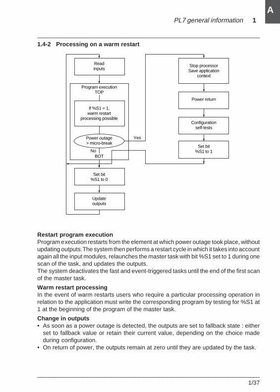
1.4-2 Processing on a warm restart
Restart program executionProgram execution restarts from the element at which power outage took place, withoutupdating outputs. The system then performs a restart cycle in which it takes into accountagain all the input modules, relaunches the master task with bit %S1 set to 1 during onescan of the task, and updates the outputs.The system deactivates the fast and event-triggered tasks until the end of the first scanof the master task.
Warm restart processingIn the event of warm restarts users who require a particular processing operation inrelation to the application must write the corresponding program by testing for %S1 at1 at the beginning of the program of the master task.
Change in outputs• As soon as a power outage is detected, the outputs are set to fallback state : either
set to fallback value or retain their current value, depending on the choice madeduring configuration.
• On return of power, the outputs remain at zero until they are updated by the task.
Program executionTOP
BOT
Readinputs
If %S1 = 1,warm restart
processing possible
Power outage> micro-break
Set bit%S1 to 0
Updateoutputs
Stop processorSave application
context
Power return
Configurationself-tests
Yes
NoSet bit
%S1 to 1
1/38___________________________________________________________________________
A
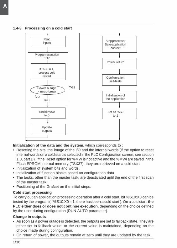
1.4-3 Processing on a cold start
Initialization of the data and the system, which corresponds to :• Resetting the bits, the image of the I/O and the internal words (if the option to reset
internal words on a cold start is selected in the PLC Configuration screen, see section1.3, part D). If the Reset option for %MW is not active and the %MWi are saved in theFlash EPROM internal memory (TSX37), they are retrieved on a cold start.
• Initialization of system bits and words.• Initialization of function blocks based on configuration data.• The tasks, other than the master task, are deactivated until the end of the first scan
of the master task.• Positioning of the Grafcet on the initial steps.
Cold start processingTo carry out an application processing operation after a cold start, bit %S10:X0 can betested by the program (if %S10:X0 = 1, there has been a cold start ). On a cold start, thePLC either does or does not continue execution , depending on the choice definedby the user during configuration (RUN AUTO parameter).
Change in outputs• As soon as a power outage is detected, the outputs are set to fallback state. They are
either set to fallback value, or the current value is maintained, depending on thechoice made during configuration.
• On return of power, the outputs remain at zero until they are updated by the task.
Readinputs
Program executionTOP
If %S0 = 1,process cold
restart
Power outage> micro-break
BOT
Set bit %S0to 0
Updateoutputs
Yes
No
Stop processorSave application
context
Power return
Configurationself-tests
Initialization ofthe application
Set bit %S0to 1
PL7 general information 1
___________________________________________________________________________1/39
A
1.5 Single task software structure
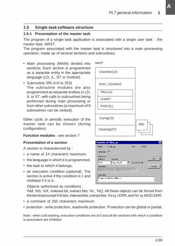
1.5-1 Presentation of the master task
The program of a single task application is associated with a single user task : themaster task, MAST.The program associated with the master task is structured into a main processingoperation, made up of several sections and subroutines.
• Main processing (MAIN) divided intosections. Each section is programmedas a separate entity in the appropriatelanguage (LD, IL, ST or Grafcet).
• Subroutine SRi (i=0 to 253)The subroutine modules are alsoprogrammed as separate entities in LD,IL or ST, with calls to subroutines beingperformed during main processing orfrom other subroutines (a maximum of 8subroutines can be nested).
Either cyclic or periodic execution of themaster task can be chosen (duringconfiguration).
Function modules : see section 7
Presentation of a section
A section is characterized by :
• a name of 24 characters maximum,
• the language in which it is programmed,
• the task to which it belongs,
• an execution condition (optional). Thesection is active if the condition is 1 andinhibited if it is 0.
Objects authorized as conditions :%M, %S, %X, indexed bit, extract bits, %I , %Q. All these objects can be forced fromthe terminal except %S bits, indexed bits, extract bits, %I xy.i.ERR, and %I xy.MOD.ERR.
• a comment of 250 characters maximum.
• protection : write protection, read/write protection. Protection can be global or partial.
Note : when cold starting, execution conditions are at 0 and all the sections with which a conditionis associated are inhibited.
Chamber(LD)
MAST
Oven_1(Grafcet)
PRL(LD)
CHART
POST(IL)
Drying(LD)
Cleaning(ST)
SR0
1/40___________________________________________________________________________
A
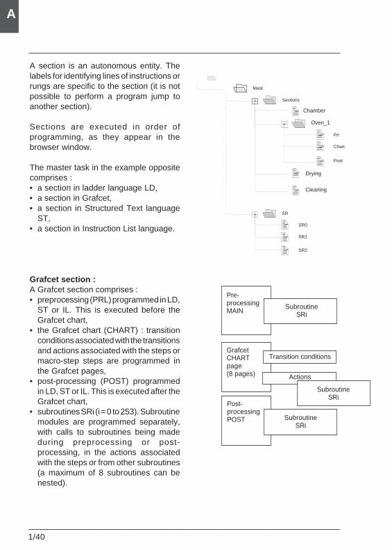
A section is an autonomous entity. Thelabels for identifying lines of instructions orrungs are specific to the section (it is notpossible to perform a program jump toanother section).
Sections are executed in order ofprogramming, as they appear in thebrowser window.
The master task in the example oppositecomprises :• a section in ladder language LD,• a section in Grafcet,• a section in Structured Text language
ST,• a section in Instruction List language.
Grafcet section :A Grafcet section comprises :• preprocessing (PRL) programmed in LD,
ST or IL. This is executed before theGrafcet chart,
• the Grafcet chart (CHART) : transitionconditions associated with the transitionsand actions associated with the steps ormacro-step steps are programmed inthe Grafcet pages,
• post-processing (POST) programmedin LD, ST or IL. This is executed after theGrafcet chart,
• subroutines SRi (i = 0 to 253). Subroutinemodules are programmed separately,with calls to subroutines being madeduring preprocessing or post-processing, in the actions associatedwith the steps or from other subroutines(a maximum of 8 subroutines can benested).
Pre-processingMAIN
GrafcetCHARTpage(8 pages)
Post-processingPOST
SubroutineSRi
Actions
SubroutineSRi
SubroutineSRi
Transition conditions
Mast
Sections
SR
Prl
Chart
Post
SR0
SR1
SR2
Chamber
Oven_1
Drying
Cleaning
PL7 general information 1
___________________________________________________________________________1/41
A
1.5-2 Cyclic execution
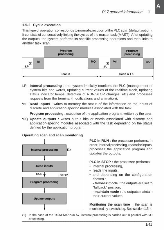
This type of operation corresponds to normal execution of the PLC scan (default option).It consists of consecutively linking the cycles of the master task (MAST). After updatingthe outputs, the system performs its specific processing operations and then links toanother task scan.
I.P. Internal processing : the system implicitly monitors the PLC (management ofsystem bits and words, updating current values of the realtime clock, updatingstatus indicator lamps, detection of RUN/STOP changes, etc) and processesrequests from the terminal (modifications and animation),
%I Read inputs : writes to memory the status of the information on the inputs ofdiscrete and application-specific modules associated with the task,
Program processing : execution of the application program, written by the user.
%Q Update outputs : writes output bits or words associated with discrete andapplication-specific modules associated with the task depending on the statusdefined by the application program.
Operating scan and scan monitoring
PLC in RUN : the processor performs, inorder, internal processing, reads the inputs,processes the application program andupdates the outputs.
PLC in STOP : the processor performs• internal processing,• reads the inputs,• and depending on the configuration
chosen :- fallback mode : the outputs are set to"fallback" position,- maintain mode : the outputs maintaintheir current values.
Monitoring the scan time : the scan ismonitored by a watchdog. See section 1.5-4.
(1) In the case of the TSX/PMX/PCX 57, internal processing is carried out in parallel with I/Oprocessing.
I.P. I.P.
%I %I%Q %Q
Programprocessing
Programprocessing
Scan n + 1Scan n
(1) (1)
Internal processing
Read inputs
Program processing
Update outputs
RUN STOP
(1)
1/42___________________________________________________________________________
A
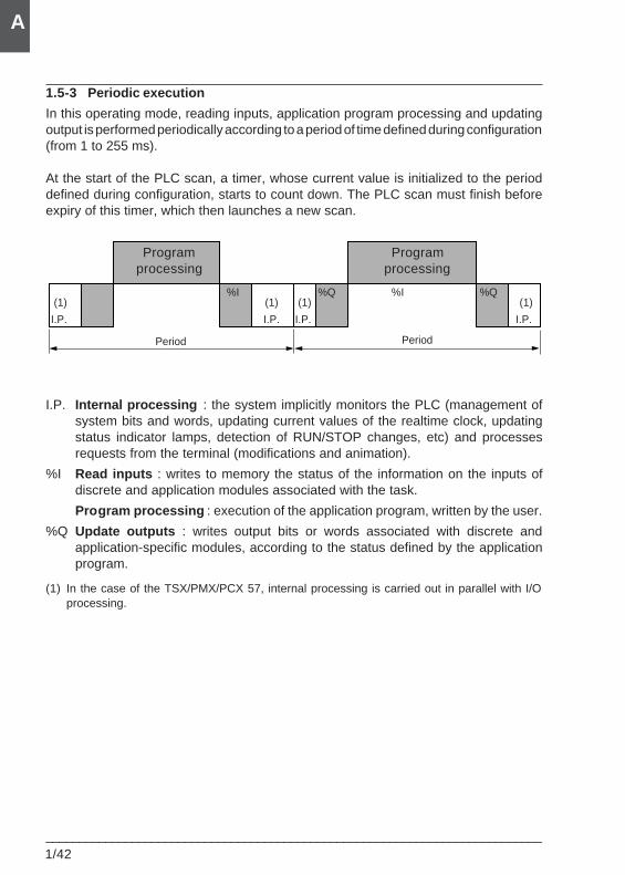
1.5-3 Periodic execution
In this operating mode, reading inputs, application program processing and updatingoutput is performed periodically according to a period of time defined during configuration(from 1 to 255 ms).
At the start of the PLC scan, a timer, whose current value is initialized to the perioddefined during configuration, starts to count down. The PLC scan must finish beforeexpiry of this timer, which then launches a new scan.
I.P. Internal processing : the system implicitly monitors the PLC (management ofsystem bits and words, updating current values of the realtime clock, updatingstatus indicator lamps, detection of RUN/STOP changes, etc) and processesrequests from the terminal (modifications and animation).
%I Read inputs : writes to memory the status of the information on the inputs ofdiscrete and application modules associated with the task.
Program processing : execution of the application program, written by the user.
%Q Update outputs : writes output bits or words associated with discrete andapplication-specific modules, according to the status defined by the applicationprogram.
(1) In the case of the TSX/PMX/PCX 57, internal processing is carried out in parallel with I/Oprocessing.
Programprocessing
Programprocessing
%I %Q %I %Q(1) (1) (1) (1)
I.P. I.P. I.P. I.P.
Period Period
PL7 general information 1
___________________________________________________________________________1/43
A
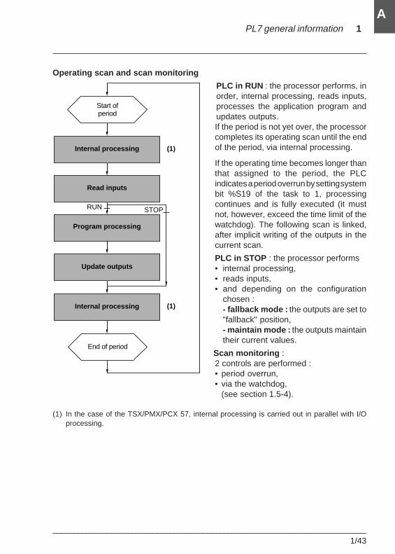
Operating scan and scan monitoring
PLC in RUN : the processor performs, inorder, internal processing, reads inputs,processes the application program andupdates outputs.If the period is not yet over, the processorcompletes its operating scan until the endof the period, via internal processing.
If the operating time becomes longer thanthat assigned to the period, the PLCindicates a period overrun by setting systembit %S19 of the task to 1, processingcontinues and is fully executed (it mustnot, however, exceed the time limit of thewatchdog). The following scan is linked,after implicit writing of the outputs in thecurrent scan.
PLC in STOP : the processor performs• internal processing,• reads inputs,• and depending on the configuration
chosen :- fallback mode : the outputs are set to"fallback" position,- maintain mode : the outputs maintaintheir current values.
Scan monitoring :2 controls are performed :• period overrun,• via the watchdog,
(see section 1.5-4).
(1) In the case of the TSX/PMX/PCX 57, internal processing is carried out in parallel with I/Oprocessing.
Internal processing
Read inputs
Program processing
Update outputs
RUN STOP
Start ofperiod
End of period
Internal processing
(1)
(1)
1/44___________________________________________________________________________
A
1.5-4 Monitoring the scan time
Software watchdog (periodic or cyclic operation)
The execution time of the master task, whether in cyclic or periodic operation, iscontrolled by the PLC (watchdog) and should not exceed the value Tmax defined duringconfiguration (250 ms default, 500 ms maximum).
In the event of an overrun, the application is declared faulty, which stops the PLCimmediately (on the TSX 37 the alarm output %Q2.0 is set to 0 if it has been configured,on the TSX/PMX/PCX 57, the alarm relay on the supply is set to 0).
Bit %S11 is used to monitor execution of this task.
It indicates a watchdog overrun. It is set to 1 by the system when the scan time becomeslonger than the watchdog.
On the TSX/PMX/PCX 57, the watchdog value must be longer than the period.
In periodic operation, an additional control is used to detect period overrun :
• %S19 : indicates a period overrun. It is set to 1 by the system when the scan timebecomes longer than the task period.
• %SW0 : this word contains the value of the period (in ms). It is initialized on a cold startby the value defined during configuration. It can be modified by the user.
Using the execution time of the master task
The following system words provide data on the scan time :
• %SW30 contains the execution time of the last scan.
• %SW31 contains the execution time of the longest scan.
• %SW32 contains the execution time of the shortest scan.
Note :This data can also be accessed from the configuration editor if requested.
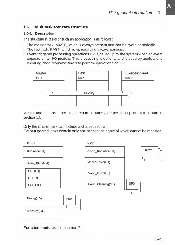
PL7 general information 1
___________________________________________________________________________1/45
A
Priority
Event-triggered tasks
Master task
+-
Fast task
1.6 Multitask software structure
1.6-1 Description
The structure in tasks of such an application is as follows :
• The master task, MAST, which is always present and can be cyclic or periodic.• The fast task, FAST, which is optional and always periodic.• Event-triggered processing operations EVTi, called up by the system when an event
appears on an I/O module. This processing is optional and is used by applicationsrequiring short response times to perform operations on I/O.
Master and fast tasks are structured in sections (see the description of a section insection 1.5).
Only the master task can include a Grafcet section.Event-triggered tasks contain only one section the name of which cannot be modified.
Chamber(LD)
MAST
Oven_1(Grafcet)
PRL(LD)
CHART
POST(IL)
Drying(LD)
Cleaning(ST)
FAST
Alarm_Chamber(LD)
Monitor_Sec(LD)
Alarm_Oven(ST)
Alarm_Cleaning(ST)
SR0
SR0
EVT0
Function modules : see section 7.
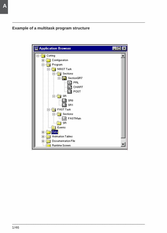
1/46___________________________________________________________________________
A
Example of a multitask program structure
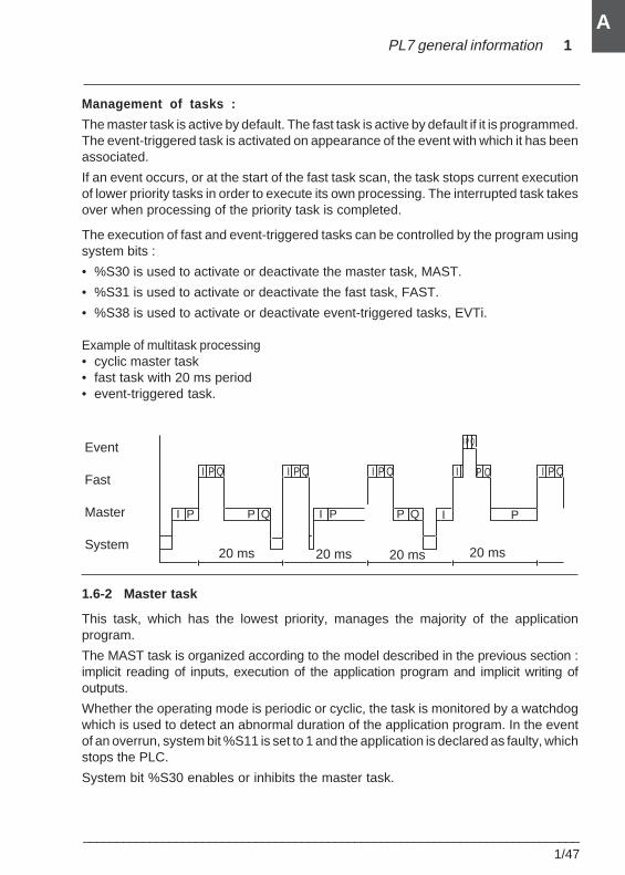
PL7 general information 1
___________________________________________________________________________1/47
A
Management of tasks :
The master task is active by default. The fast task is active by default if it is programmed.The event-triggered task is activated on appearance of the event with which it has beenassociated.
If an event occurs, or at the start of the fast task scan, the task stops current executionof lower priority tasks in order to execute its own processing. The interrupted task takesover when processing of the priority task is completed.
The execution of fast and event-triggered tasks can be controlled by the program usingsystem bits :
• %S30 is used to activate or deactivate the master task, MAST.
• %S31 is used to activate or deactivate the fast task, FAST.
• %S38 is used to activate or deactivate event-triggered tasks, EVTi.
Example of multitask processing• cyclic master task• fast task with 20 ms period• event-triggered task.
1.6-2 Master task
This task, which has the lowest priority, manages the majority of the applicationprogram.
The MAST task is organized according to the model described in the previous section :implicit reading of inputs, execution of the application program and implicit writing ofoutputs.
Whether the operating mode is periodic or cyclic, the task is monitored by a watchdogwhich is used to detect an abnormal duration of the application program. In the eventof an overrun, system bit %S11 is set to 1 and the application is declared as faulty, whichstops the PLC.
System bit %S30 enables or inhibits the master task.
I P Q
I
Event
Fast
Master
System
P Q
I P I PP Q P Q I P
20 ms 20 ms 20 ms 20 ms
I P Q I P Q I P Q I P Q
1/48___________________________________________________________________________
A
1.6-3 Fast task
This task, which is higher priority than the master task MAST, is periodic in order to leavetime for execution of the lower priority task.
In addition, the processing operations which are associated with it should therefore beshort, to avoid adversely affecting the master task. Like the master task, the associatedprogram consists of sections and subroutines.
The period of the fast task, FAST, is set during configuration, from 1 to 255 ms. This canbe defined as longer than that of the master task, MAST, in order to adapt it to periodicprocessing operations which are slow but have higher priority. The program executedshould however remain short to avoid overrun of lower priority tasks.
The fast task is monitored by a watchdog which is used to detect an abnormal durationof the application program. In the event of an overrun, system bit %S11 is set to 1 andthe application is declared as faulty, which stops the PLC.
Control of the fast task
System word %SW1 contains the value of the period. It is initialized on a cold start bythe value defined during configuration and can be modified by the user by program orvia the terminal.
System bits and words are used to monitor execution of this task :
• %S19 : indicates a period overrun. It is set to 1 by the system when the scan timebecomes longer than the task period.
• %S31 : is used to enable or inhibit the fast task. It is set to 0 by the system on a coldstart of the application, at the end of the first scan of the master task. It is set to 1 or0 to enable or inhibit the fast task.
Display of the fast task execution times
The following system words provide data on scan times :• %SW33 contains the execution time of the last scan.• %SW34 contains the execution time of the longest scan.• %SW35 contains the execution time of the shortest scan.
PL7 general information 1
___________________________________________________________________________1/49
A
1.6-4 Assigning I/O channels to the master and fast tasks
In addition to the application program, the MAST and FAST tasks execute systemfunctions linked to the management of implicit I/O which are associated with them.
Associating a channel or a group of channels with a task is defined in the configurationscreen for the corresponding module. The default associated task is the MAST task.
Since the modularity of discrete modules is 8 consecutive channels (channels 0 to 7,channels 8 to 15, etc), I/O can be assigned in groups of 8 channels, either to the MASTor FAST task. For example, it is possible to assign the channels of a 28 I/O module inthe following way :
• Inputs 0 to 7 assigned to the MAST task.
• Inputs 8 to 15 assigned to the FAST task.
• Outputs 0 to 7 assigned to the MAST task.
• Outputs 8 to 11 assigned to the FAST task.
Each channel of a counter module can be assigned either to the MAST or FAST task.For example, for a 2 channel counter module, it is possible to assign :
• channel 0 to the MAST task and,
• channel 1 to the FAST task.
The channels of TSX 37 analog input modules must be assigned to the MAST task.However, it is possible to assign analog output channels to either the MAST or FASTtask, with 2 channel modularity. For example, for a module with 4 analog outputs, it ispossible to assign :
• channels 0 and 1 to the MAST task and,
• channels 2 and 3 to the FAST task.
The channels of TSX 57 analog I/O modules can be assigned to the MAST or FAST task.Each channel of the isolated analog I/O modules (4 isolated channels) is assigned onan individual basis. A 4-channel modularity is used for other modules.
1/50___________________________________________________________________________
A
1.6-5 Event-triggered tasks
Event-triggered processing is used to reduce the response time of the software oncommand events.
Command eventsThese are external events associated with applications. The appearance of such anevent diverts the application program to the processing operation associated with theI/O channel which caused the event. The inputs (%I, %IW, %ID) associated with the I/Ochannel which triggered the event are updated by the system before calling up eventprocessing. It is possible to configure :
• 8 events in a TSX 37-05/08/10 PLC (EVT1 to EVT8).• 16 events in a TSX 37-21/22 PLC (EVT0 to EVT15).• 32 events in a TSX/PMX/PCX 57-10 PLC (EVT0 to EVT31).• 64 events in a TSX/PMX/PCX 57-20 PLC (EVT0 to EVT63).
The association between a channel and an event number is created in the channelconfiguration screen.
On the TSX 37, event processing can be triggered by :
• Inputs 0 to 3 of module in position 1, on a rising or falling edge.• The counter channel(s) of counter modules.• The counter channels of module 1 (if this is configured as a counter).• Reception of a telegram in a TSX 37-21/22 fitted with a TSX FPP20 module.
On the TSX/PMX/PCX 57, event processing can be triggered by :
• The inputs of DEY 16 FK, DMY 28 FK and DMY 28 RFK modules.• The channels of counter modules.• The channels of CAY axis control modules.• The channels of CFY stepper motor control modules.• Communication channels "FPP20".
Management of event-triggered tasksEvent-triggered processing can be globally enabled or inhibited by the applicationprogram, using system bit %S38. If one or more events occur while they are inhibited,the associated processing operations are lost.
Two PL7 language instructions MASKEVT() and UNMASKEVT(), used in the applicationprogram, also allow masking or unmasking of event-triggered processing. If one or moreevents occur while they are masked, they are saved by the system and the associatedprocessing will only be carried out after unmasking.
The 8 possible command events with a TSX 37-05/08/10 PLC all have the same level ofpriority. Thus, one event processing operation cannot be interrupted by another. Witha TSX 37-21/22 or a TSX/PMX/PCX 57 PLC, there are 2 levels of priority for commandevents : event 0 (EVT0) has higher priority than the other events.
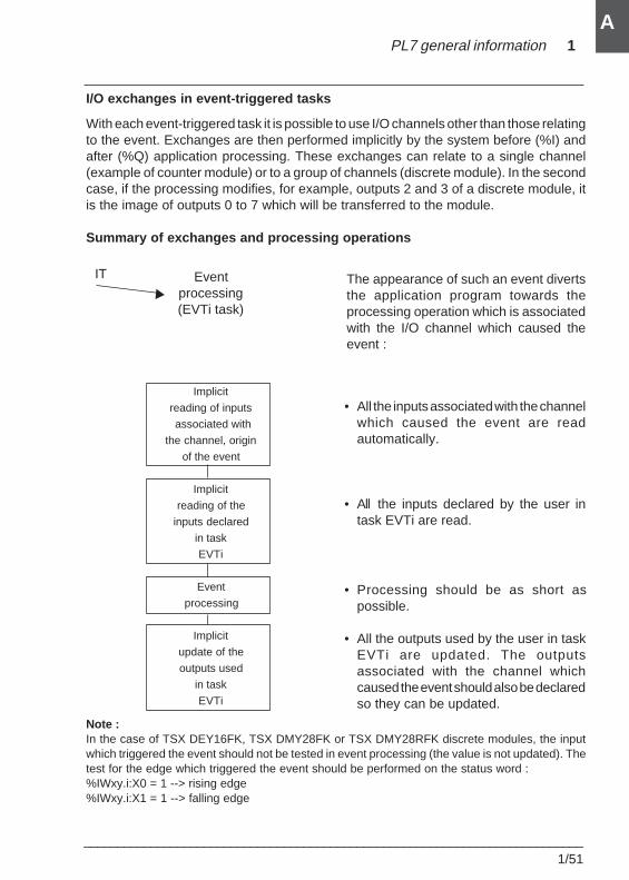
PL7 general information 1
___________________________________________________________________________1/51
A
I/O exchanges in event-triggered tasks
With each event-triggered task it is possible to use I/O channels other than those relatingto the event. Exchanges are then performed implicitly by the system before (%I) andafter (%Q) application processing. These exchanges can relate to a single channel(example of counter module) or to a group of channels (discrete module). In the secondcase, if the processing modifies, for example, outputs 2 and 3 of a discrete module, itis the image of outputs 0 to 7 which will be transferred to the module.
Summary of exchanges and processing operations
The appearance of such an event divertsthe application program towards theprocessing operation which is associatedwith the I/O channel which caused theevent :
• All the inputs associated with the channelwhich caused the event are readautomatically.
• All the inputs declared by the user intask EVTi are read.
• Processing should be as short aspossible.
• All the outputs used by the user in taskEVTi are updated. The outputsassociated with the channel whichcaused the event should also be declaredso they can be updated.
Note :In the case of TSX DEY16FK, TSX DMY28FK or TSX DMY28RFK discrete modules, the inputwhich triggered the event should not be tested in event processing (the value is not updated). Thetest for the edge which triggered the event should be performed on the status word :%IWxy.i:X0 = 1 --> rising edge%IWxy.i:X1 = 1 --> falling edge
Eventprocessing(EVTi task)
Implicit
reading of inputs
associated with
the channel, origin
of the event
Implicit
reading of the
inputs declared
in task
EVTi
Event
processing
Implicit
update of the
outputs used
in task
EVTi
IT
r
1/52___________________________________________________________________________
A
NotesOn the TSX 37, analog input modules, which can only be used in the MAST task,should not be exchanged in event processing.
The exchange of I/O, associated with the EVTi task and used by the program, isperformed channel by channel (for counter modules) or in groups of channels (fordiscrete modules). For this reason, if processing modifies, for example, outputs2 and 3 of a discrete module, it is the image of outputs 0 to 7 which will be transferredto the module.
On the TSX 37, for each event-triggered processing operation, it is possible todeclare a maximum of exchanges for 2 input modules (before processing of theevent) and 2 output modules (after processing of the event).
The inputs exchanged (and the group of associated channels) duringevent-triggered processing are updated (loss of log values and, consequently,edges). Thus, edges should not be tested on these inputs in the master (MAST)or fast (FAST) tasks.
On the TSX/PMX/PCX 57, depending on the processor used, the number of exchangesused is limited :
No. of exchanges which can P57-1• (32 EVTs) P57-2•/3• (64 EVTs)be used in EVTs by processor
Max. no. of discrete exchanges 32 exchanges 128 exchanges
Max. no. of analog exchanges 8 exchanges 16 exchanges
Max. no. of other application- 4 exchanges 16 exchangesspecific exchanges
For discrete I/O, an exchange involves a group of 8 channels. It is generated when theinputs of a group of 8 channels are used (other than the group of channels whichgenerate the event) and when writing the outputs of a group of 8 channels.
For analog or other application-specific I/O, an exchange is generated when the inputsof a channel are used (other than the channel which generates the event) and whenwriting the outputs of a channel.
Display of the number of events processed
Word %SW48 shows the number of events processed. This word is initialized to 0 ona cold start, then incremented by the system when an event is launched. This word canbe modified by the user.
%S39 indicates loss of event.
Note :A summary of the operations to be performed to program events is given in part A, section 5.3of the application-specific manual.
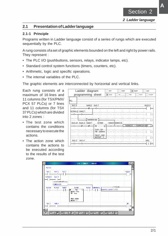
Ladder language 2
___________________________________________________________________________2/1
A
2.1 Presentation of Ladder language
2.1-1 Principle
Programs written in Ladder language consist of a series of rungs which are executedsequentially by the PLC.
A rung consists of a set of graphic elements bounded on the left and right by power rails.They represent :
• The PLC I/O (pushbuttons, sensors, relays, indicator lamps, etc).
• Standard control system functions (timers, counters, etc).
• Arithmetic, logic and specific operations.
• The internal variables of the PLC.
The graphic elements are interconnected by horizontal and vertical links.
Each rung consists of amaximum of 16 lines and11 columns (for TSX/PMX/PCX 57 PLCs) or 7 linesand 11 columns (for TSX37 PLCs) which are dividedinto 2 zones :
• The test zone whichcontains the conditionsnecessary to execute theactions.
• The action zone whichcontains the actions tobe executed accordingto the results of the testzone.
MAIN
EVT
SR
FAST
PRE
MAST
POST
AUX
CHART
% L
%I1.0 %M12 %Q2.5%I3.7
%TM4.Q %M17
%MW4<50
%MW15 : = %MW18+500%TM0%I3.10 %Q4.3
IN
TYP : TPTB : 100ms
TM.P : 200MODIF : Y
Q
SR1
C
%I1.2 %I1.4
%M27 %M25 %MW0:X5
Section 22 Ladder language
Ladder diagram programming sheet
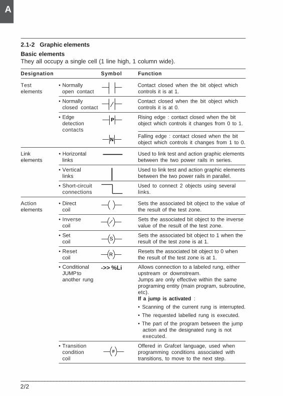
2/2___________________________________________________________________________
A
2.1-2 Graphic elements
Basic elementsThey all occupy a single cell (1 line high, 1 column wide).
Designation Symbol Function
Test • Normally Contact closed when the bit object whichelements open contact controls it is at 1.
• Normally Contact closed when the bit object whichclosed contact controls it is at 0.
• Edge Rising edge : contact closed when the bitdetection object which controls it changes from 0 to 1.contacts
Falling edge : contact closed when the bitobject which controls it changes from 1 to 0.
Link • Horizontal Used to link test and action graphic elementselements links between the two power rails in series.
• Vertical Used to link test and action graphic elementslinks between the two power rails in parallel.
• Short-circuit Used to connect 2 objects using severalconnections links.
Action • Direct Sets the associated bit object to the value ofelements coil the result of the test zone.
• Inverse Sets the associated bit object to the inversecoil value of the result of the test zone.
• Set Sets the associated bit object to 1 when thecoil result of the test zone is at 1.
• Reset Resets the associated bit object to 0 whencoil the result of the test zone is at 1.
• Conditional Allows connection to a labeled rung, eitherJUMP to upstream or downstream.another rung Jumps are only effective within the same
programing entity (main program, subroutine,etc).If a jump is activated :
• Scanning of the current rung is interrupted.
• The requested labelled rung is executed.
• The part of the program between the jumpaction and the designated rung is notexecuted.
• Transition Offered in Grafcet language, used whencondition programming conditions associated withcoil transitions, to move to the next step.
R
S
N
P
->> %Li
#
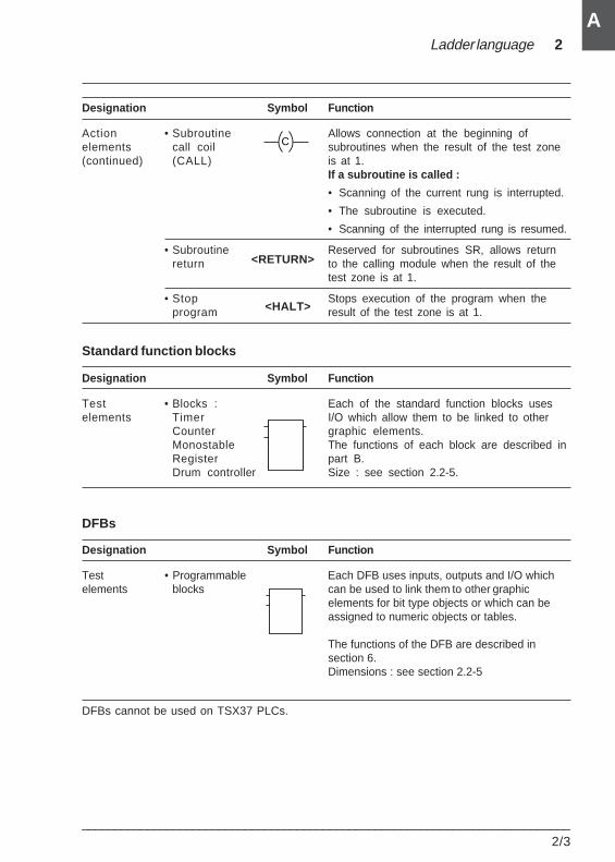
Ladder language 2
___________________________________________________________________________2/3
A
Designation Symbol Function
Action • Subroutine Allows connection at the beginning ofelements call coil subroutines when the result of the test zone(continued) (CALL) is at 1.
If a subroutine is called :
• Scanning of the current rung is interrupted.
• The subroutine is executed.
• Scanning of the interrupted rung is resumed.
• Subroutine Reserved for subroutines SR, allows returnreturn to the calling module when the result of the
test zone is at 1.
• Stop Stops execution of the program when theprogram result of the test zone is at 1.
Standard function blocks
Designation Symbol Function
Test • Blocks : Each of the standard function blocks useselements Timer I/O which allow them to be linked to other
Counter graphic elements.Monostable The functions of each block are described inRegister part B.Drum controller Size : see section 2.2-5.
DFBs
Designation Symbol Function
Test • Programmable Each DFB uses inputs, outputs and I/O whichelements blocks can be used to link them to other graphic
elements for bit type objects or which can beassigned to numeric objects or tables.
The functions of the DFB are described insection 6.Dimensions : see section 2.2-5
DFBs cannot be used on TSX37 PLCs.
<RETURN>
<HALT>
C
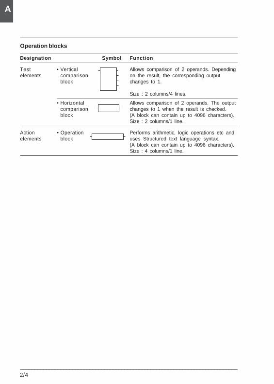
2/4___________________________________________________________________________
A
Operation blocks
Designation Symbol Function
Test • Vertical Allows comparison of 2 operands. Dependingelements comparison on the result, the corresponding output
block changes to 1.
Size : 2 columns/4 lines.
• Horizontal Allows comparison of 2 operands. The outputcomparison changes to 1 when the result is checked.block (A block can contain up to 4096 characters).
Size : 2 columns/1 line.
Action • Operation Performs arithmetic, logic operations etc andelements block uses Structured text language syntax.
(A block can contain up to 4096 characters).Size : 4 columns/1 line.
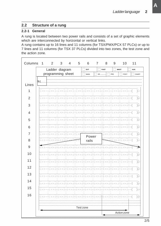
Ladder language 2
___________________________________________________________________________2/5
A
2.2 Structure of a rung
2.2-1 General
A rung is located between two power rails and consists of a set of graphic elementswhich are interconnected by horizontal or vertical links.A rung contains up to 16 lines and 11 columns (for TSX/PMX/PCX 57 PLCs) or up to7 lines and 11 columns (for TSX 37 PLCs) divided into two zones, the test zone andthe action zone.
MAIN
EVT
SR
FAST
PRE
MAST
POST
AUX
CHART
% L
1 2 3 4 5 6 7 8 9 10 11
Lines
1
2
3
4
5
6
7
8
9
10
11
12
13
14
15
16
Columns
Test zone
Action zone
Powerrails
Ladder diagramprogramming sheet
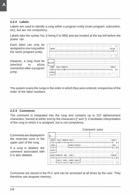
2/6___________________________________________________________________________
A
2.2-2 Labels
Labels are used to identify a rung within a program entity (main program, subroutine,etc), but are not compulsory.
Labels take the syntax %Li (i being 0 to 999) and are located at the top left before thepower rail.
Each label can only beassigned to one rung withinthe same program entity.
However, a rung must belabelled to allowconnection after a programjump.
The system scans the rungs in the order in which they were entered, irrespective of theorder of the label numbers.
2.2-3 Comments
The comment is integrated into the rung and contains up to 222 alphanumericcharacters, framed at either end by the characters (* and *). It facilitates interpretationof the rung to which it is assigned, but is not compulsory.
Comments are displayed inthe reserved zone in theupper part of the rung.
If a rung is deleted, thecomment associated withit is also deleted.
Comments are stored in the PLC and can be accessed at all times by the user. Theytherefore use program memory.
%L245%M20
% L2 4 5
%M3 %Q2.1%I1.6 %MW1:X2
%TM4.D
% L
%Q2.3 %Q4.7%I1.4 %MW2:X9
%M16
%I1.3
SR4C
%M12 %TM3.Q
%C8.E
%Q2.0 %M155%MW3:X0 %M3 %I5.2
S%I1.3 %I3.1 %M13 %Q4.7
Comment zone
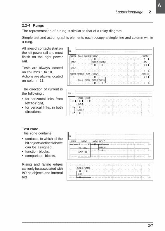
Ladder language 2
___________________________________________________________________________2/7
A
2.2-4 Rungs
The representation of a rung is similar to that of a relay diagram.
Simple test and action graphic elements each occupy a single line and column withina rung.
All lines of contacts start onthe left power rail and mustfinish on the right powerrail.
Tests are always locatedon columns 1 to 10.Actions are always locatedon column 11.
The direction of current isthe following :
• for horizontal links, fromleft to right ,
• for vertical links, in bothdirections.
Test zoneThis zone contains :
• contacts, to which all thebit objects defined abovecan be assigned,
• function blocks,• comparison blocks.
Rising and falling edgescan only be associated withI/O bit objects and internalbits.
% L
%Q2.3 %Q4.7%I1.4 %MW2:X9
%M16
%I1.3
SR4C
%M12 %TM3.Q
%C8.E
%Q2.0 %M155%MW3:X0 %M3 %I5.2
S%I1.3 %I3.1 %M13 %Q4.7
% L
%M16 %T3.D
%I5.4
%C13.E
%Q2.6 %M85
%S6
% L
%I6.8S
TB : 100ms
MN.P : 80
%C2.D
%MW8:X4
%MN0%M9R
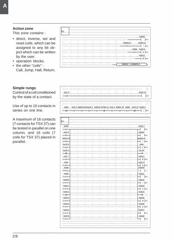
2/8___________________________________________________________________________
A
Action zoneThis zone contains :
• direct, inverse, set andreset coils, which can beassigned to any bit ob-ject which can be writtenby the user.
• operation blocks.• the other "coils" :
Call, Jump, Halt, Return.
Simple rungsControl of a coil conditionedby the state of a contact.
Use of up to 10 contacts inseries on one line.
A maximum of 16 contacts(7 contacts for TSX 37) canbe tested in parallel on onecolumn, and 16 coils (7coils for TSX 37) placed inparallel.
% L
%M52
%MW2 := %MW0+1
%MW8:X10%MW8:X1/
%Q6.5%M8S
%M12R
%I1.3 %Q4.12
%M1 %Q6.3%I3.2 %MW18:X4%Q4.2 %M15 %TM2.Q %I3.4 %MW1:X5 %M5 %C0.D
/
% L
%M5 %Q6.2
%M25
%MW8:X0
SR9
%L20
%M12
%Q2.6S
R
C
/
%I6.9
%MW15:X5
%C6.E
%Q5.2
%I3.7
%S4
%M8 %M30
%M31
%M32
%M33
%M34
%M35
%M36S
R
C
/
%M9
%M10
%M11
%M12
%M13
%M14
%M15 %M37
%M38%M16
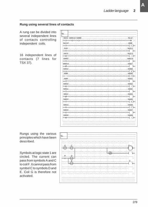
Ladder language 2
___________________________________________________________________________2/9
A
Rung using several lines of contacts
A rung can be divided intoseveral independent linesof contacts controllingindependent coils.
16 independent lines ofcontacts (7 lines forTSX 37).
Rungs using the variousprinciples which have beendescribed.
Symbols at logic state 1 arecircled. The current canpass from symbols A and Cto coil F. It cannot pass fromsymbol C to symbols D andE. Coil G is therefore notactivated.
% L
FA C
G
B D
E
% L
%I3.2 %L12
SRØ
%Q3.2
%Q3.3
%MW3:X6
%M27
%M68S
/
%C2.E
%S4
%I6.5
%M53
%MW8:X4
%M12
%MW6:X10 %M88
P
C
%M30
%M31
%M32
%M33
%M34
%M35S
/
%M8
%M9
%M10
%M11
%M12
%M13
P
C
%M36
%M37
%M38/
%M14
%M15
%M16P
C
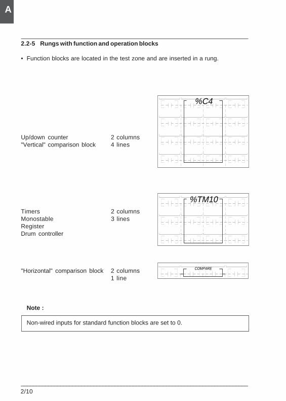
2/10___________________________________________________________________________
A
%TM10
%C4
2.2-5 Rungs with function and operation blocks
• Function blocks are located in the test zone and are inserted in a rung.
Up/down counter 2 columns"Vertical" comparison block 4 lines
Timers 2 columnsMonostable 3 linesRegisterDrum controller
"Horizontal" comparison block 2 columns1 line
Note :
Non-wired inputs for standard function blocks are set to 0.
COMPARE
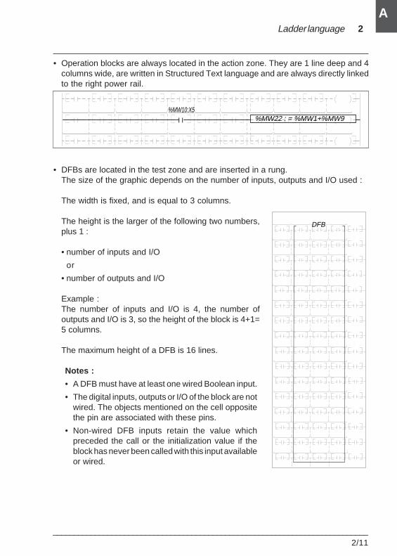
Ladder language 2
___________________________________________________________________________2/11
A
• Operation blocks are always located in the action zone. They are 1 line deep and 4columns wide, are written in Structured Text language and are always directly linkedto the right power rail.
• DFBs are located in the test zone and are inserted in a rung.The size of the graphic depends on the number of inputs, outputs and I/O used :
The width is fixed, and is equal to 3 columns.
The height is the larger of the following two numbers,plus 1 :
• number of inputs and I/O
or
• number of outputs and I/O
Example :The number of inputs and I/O is 4, the number ofoutputs and I/O is 3, so the height of the block is 4+1=5 columns.
The maximum height of a DFB is 16 lines.
Notes :
• A DFB must have at least one wired Boolean input.
• The digital inputs, outputs or I/O of the block are notwired. The objects mentioned on the cell oppositethe pin are associated with these pins.
• Non-wired DFB inputs retain the value whichpreceded the call or the initialization value if theblock has never been called with this input availableor wired.
%MW22 : = %MW1+%MW9%MW10:X5
DFB
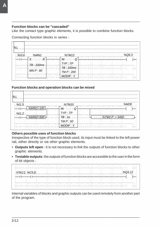
2/12___________________________________________________________________________
A
Function blocks can be "cascaded"Like the contact type graphic elements, it is possible to combine function blocks.
Connecting function blocks in series :
Function blocks and operation blocks can be mixed
Others possible uses of function blocksIrrespective of the type of function block used, its input must be linked to the left powerrail, either directly or via other graphic elements.
• Outputs left open : it is not necessary to link the outputs of function blocks to othergraphic elements.
• Testable outputs : the outputs of function blocks are accessible to the user in the formof bit objects :
Internal variables of blocks and graphic outputs can be used remotely from another partof the program.
% L
%MW1>100%TM10
INTYP : TPTB : 1sTM.P : 50MODIF : Y
Q%I1.5 %M28
%MW2>500%I1.2
%TM2.P := 3450
%TM12.Q %Q4.12%C5.E
% L
%MN1S
TB : 100ms
MN.P : 80
R%TM12
INTYP : TPTB : 100msTM.P : 200MODIF : Y
Q%I3.6 %Q6.3
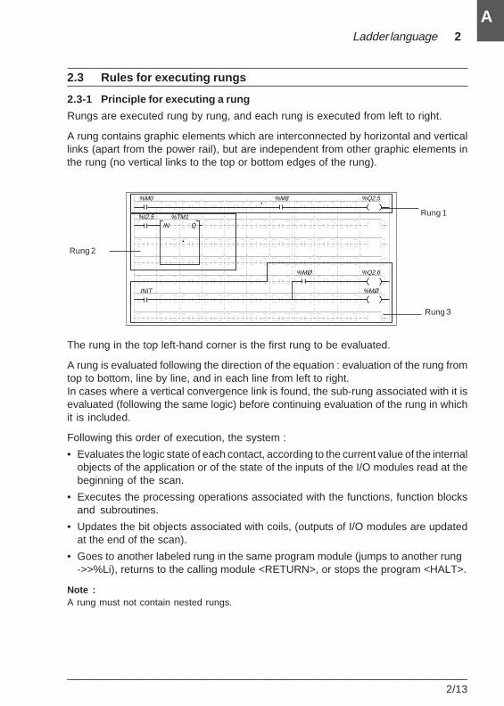
Ladder language 2
___________________________________________________________________________2/13
A
2.3 Rules for executing rungs
2.3-1 Principle for executing a rung
Rungs are executed rung by rung, and each rung is executed from left to right.
A rung contains graphic elements which are interconnected by horizontal and verticallinks (apart from the power rail), but are independent from other graphic elements inthe rung (no vertical links to the top or bottom edges of the rung).
The rung in the top left-hand corner is the first rung to be evaluated.
A rung is evaluated following the direction of the equation : evaluation of the rung fromtop to bottom, line by line, and in each line from left to right.In cases where a vertical convergence link is found, the sub-rung associated with it isevaluated (following the same logic) before continuing evaluation of the rung in whichit is included.
Following this order of execution, the system :
• Evaluates the logic state of each contact, according to the current value of the internalobjects of the application or of the state of the inputs of the I/O modules read at thebeginning of the scan.
• Executes the processing operations associated with the functions, function blocksand subroutines.
• Updates the bit objects associated with coils, (outputs of I/O modules are updatedat the end of the scan).
• Goes to another labeled rung in the same program module (jumps to another rung ->>%Li), returns to the calling module <RETURN>, or stops the program <HALT>.
Note :A rung must not contain nested rungs.
%Q2.5%M0 %M8
%I2.5 %TM1IN Q
%MØINIT
%Q2.6%MØ
Rung 1
Rung 3
Rung 2
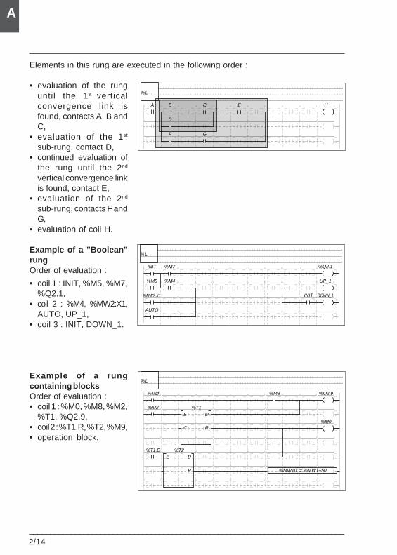
2/14___________________________________________________________________________
A
Elements in this rung are executed in the following order :
• evaluation of the runguntil the 1st verticalconvergence link isfound, contacts A, B andC,
• evaluation of the 1st
sub-rung, contact D,• continued evaluation of
the rung until the 2nd
vertical convergence linkis found, contact E,
• evaluation of the 2nd
sub-rung, contacts F andG,
• evaluation of coil H.
Example of a "Boolean"rungOrder of evaluation :
• coil 1 : INIT, %M5, %M7,%Q2.1,
• coil 2 : %M4, %MW2:X1,AUTO, UP_1,
• coil 3 : INIT, DOWN_1.
Example of a rungcontaining blocksOrder of evaluation :• coil 1 : %M0, %M8, %M2,
%T1, %Q2.9,• coil 2 : %T1.R, %T2, %M9,• operation block.
% L
A HB C E
D
F G
% L
INIT %Q2.1%M7
UP_1
DOWN_1
%M5 %M4
%MW2:X1
AUTO
INIT
% L
%Q2.9%MØ %M8
%M9
%M2 %T1E
C
D
R
%T2D
R
%T1.DE
C %MW10 := %MW1+50
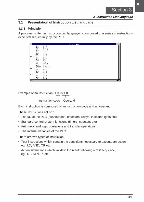
Instruction List language 3
___________________________________________________________________________3/1
A
3.1 Presentation of Instruction List language
3.1-1 Principle
A program written in Instruction List language is composed of a series of instructionsexecuted sequentially by the PLC.
Example of an instruction : LD %I1.0
Instruction code Operand
Each instruction is composed of an instruction code and an operand.
These instructions act on :
• The I/O of the PLC (pushbuttons, detectors, relays, indicator lights etc).
• Standard control system functions (timers, counters etc).
• Arithmetic and logic operations and transfer operations.
• The internal variables of the PLC.
There are two types of instruction :
• Test instructions which contain the conditions necessary to execute an action,eg : LD, AND, OR etc.
• Action instructions which validate the result following a test sequence,eg : ST, STN, R, etc.
Section 33 Instruction List language
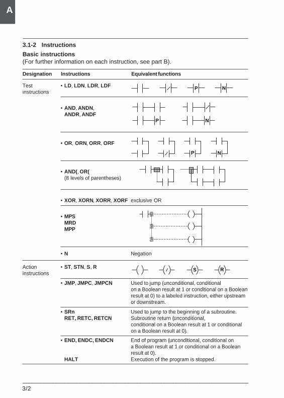
3/2___________________________________________________________________________
A
3.1-2 Instructions
Basic instructions(For further information on each instruction, see part B).
Designation Instructions Equivalent functions
Test • LD, LDN, LDR, LDFinstructions
• AND, ANDN,ANDR, ANDF
• OR, ORN, ORR, ORF
• AND(, OR((8 levels of parentheses)
• XOR, XORN, XORR, XORF exclusive OR
• MPSMRDMPP
• N Negation
Action • ST, STN, S, Rinstructions
• JMP, JMPC, JMPCN Used to jump (unconditional, conditionalon a Boolean result at 1 or conditional on a Booleanresult at 0) to a labeled instruction, either upstreamor downstream.
• SRn Used to jump to the beginning of a subroutine.RET, RETC, RETCN Subroutine return (unconditional,
conditional on a Boolean result at 1 or conditionalon a Boolean result at 0).
• END, ENDC, ENDCN End of program (unconditional, conditional ona Boolean result at 1 or conditional on a Booleanresult at 0).
HALT Execution of the program is stopped.
P N
P N
P N
S R
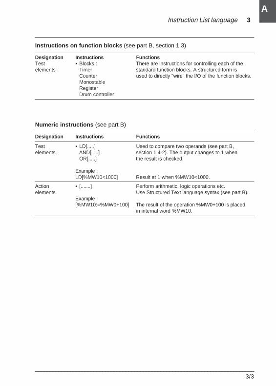
Instruction List language 3
___________________________________________________________________________3/3
A
Instructions on function blocks (see part B, section 1.3)
Designation Instructions FunctionsTest • Blocks : There are instructions for controlling each of theelements Timer standard function blocks. A structured form is
Counter used to directly "wire" the I/O of the function blocks.MonostableRegisterDrum controller
Numeric instructions (see part B)
Designation Instructions Functions
Test • LD[.....] Used to compare two operands (see part B,elements AND[.....] section 1.4-2). The output changes to 1 when
OR[.....] the result is checked.
Example :LD[%MW10<1000] Result at 1 when %MW10<1000.
Action • [.......] Perform arithmetic, logic operations etc.elements Use Structured Text language syntax (see part B).
Example :[%MW10:=%MW0+100] The result of the operation %MW0+100 is placed
in internal word %MW10.
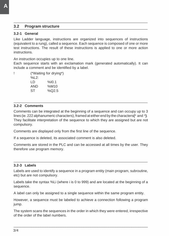
3/4___________________________________________________________________________
A
3.2 Program structure
3.2-1 General
Like Ladder language, instructions are organized into sequences of instructions(equivalent to a rung), called a sequence. Each sequence is composed of one or moretest instructions. The result of these instructions is applied to one or more actioninstructions.
An instruction occupies up to one line.Each sequence starts with an exclamation mark (generated automatically). It caninclude a comment and be identified by a label.
! (*Waiting for drying*)%L2:LD %I0.1AND %M10ST %Q2.5
3.2-2 Comments
Comments can be integrated at the beginning of a sequence and can occupy up to 3lines (ie. 222 alphanumeric characters), framed at either end by the characters (* and *).They facilitate interpretation of the sequence to which they are assigned but are notcompulsory.
Comments are displayed only from the first line of the sequence.
If a sequence is deleted, its associated comment is also deleted.
Comments are stored in the PLC and can be accessed at all times by the user. Theytherefore use program memory.
3.2-3 Labels
Labels are used to identify a sequence in a program entity (main program, subroutine,etc) but are not compulsory.
Labels take the syntax %Li (where i is 0 to 999) and are located at the beginning of asequence.
A label can only be assigned to a single sequence within the same program entity.
However, a sequence must be labeled to achieve a connection following a programjump.
The system scans the sequences in the order in which they were entered, irrespectiveof the order of the label numbers.
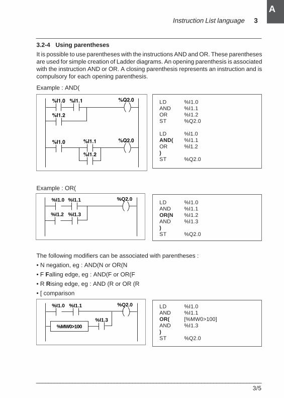
Instruction List language 3
___________________________________________________________________________3/5
A
3.2-4 Using parentheses
It is possible to use parentheses with the instructions AND and OR. These parenthesesare used for simple creation of Ladder diagrams. An opening parenthesis is associatedwith the instruction AND or OR. A closing parenthesis represents an instruction and iscompulsory for each opening parenthesis.
Example : AND(
LD %I1.0AND %I1.1OR %I1.2ST %Q2.0
LD %l1.0AND( %I1.1OR %l1.2)ST %Q2.0
Example : OR(
LD %I1.0AND %I1.1OR(N %I1.2AND %I1.3)ST %Q2.0
The following modifiers can be associated with parentheses :
• N negation, eg : AND(N or OR(N
• F Falling edge, eg : AND(F or OR(F
• R Rising edge, eg : AND (R or OR (R
• [ comparison
LD %I1.0AND %I1.1OR( [%MW0>100]AND %I1.3)ST %Q2.0
%Q2.0%I1.1%I1.0
%I1.3%I1.2
%Q2.0%I1.1%I1.0
%I1.3%MW0>100
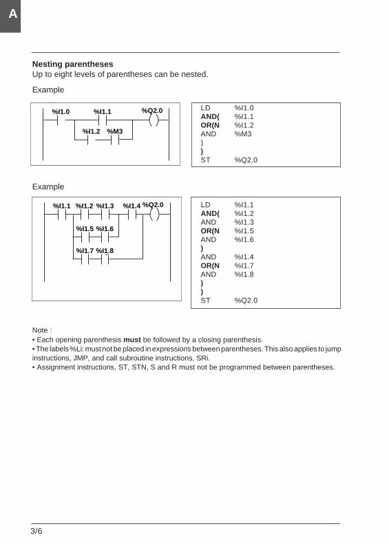
3/6___________________________________________________________________________
A
Nesting parenthesesUp to eight levels of parentheses can be nested.
Example
LD %I1.0AND( %I1.1OR(N %I1.2AND %M3))ST %Q2.0
Example
LD %I1.1AND( %I1.2AND %I1.3OR(N %I1.5AND %I1.6)AND %I1.4OR(N %I1.7AND %I1.8))ST %Q2.0
Note :• Each opening parenthesis must be followed by a closing parenthesis.• The labels %Li: must not be placed in expressions between parentheses. This also applies to jumpinstructions, JMP, and call subroutine instructions, SRi.• Assignment instructions, ST, STN, S and R must not be programmed between parentheses.
%Q2.0%I1.1%I1.0
%M3%I1.2
%Q2.0%I1.2%I1.1
%I1.6%I1.5
%I1.8%I1.7
%I1.4%I1.3
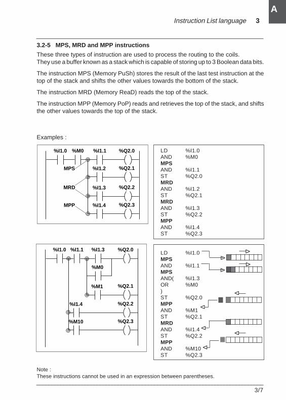
Instruction List language 3
___________________________________________________________________________3/7
A
%I1.2MPS
MRD
MPP
%I1.1 %Q2.0
%I1.3
%Q2.1
%Q2.2
%I1.4 %Q2.3
%M0%I1.0
%M0
%I1.3 %Q2.0
%I1.4
%Q2.1
%Q2.2
%M1
%M10 %Q2.3
%I1.1%I1.0
∆
∆
∆∆
∆
∆
3.2-5 MPS, MRD and MPP instructions
These three types of instruction are used to process the routing to the coils.They use a buffer known as a stack which is capable of storing up to 3 Boolean data bits.
The instruction MPS (Memory PuSh) stores the result of the last test instruction at thetop of the stack and shifts the other values towards the bottom of the stack.
The instruction MRD (Memory ReaD) reads the top of the stack.
The instruction MPP (Memory PoP) reads and retrieves the top of the stack, and shiftsthe other values towards the top of the stack.
Examples :
LD %I1.0AND %M0MPSAND %I1.1ST %Q2.0MRDAND %I1.2ST %Q2.1MRDAND %I1.3ST %Q2.2MPPAND %I1.4ST %Q2.3
LD %I1.0MPSAND %I1.1MPSAND( %I1.3OR %M0)ST %Q2.0MPPAND %M1ST %Q2.1MRDAND %I1.4ST %Q2.2MPPAND %M10ST %Q2.3
Note :These instructions cannot be used in an expression between parentheses.
∆
∆∆
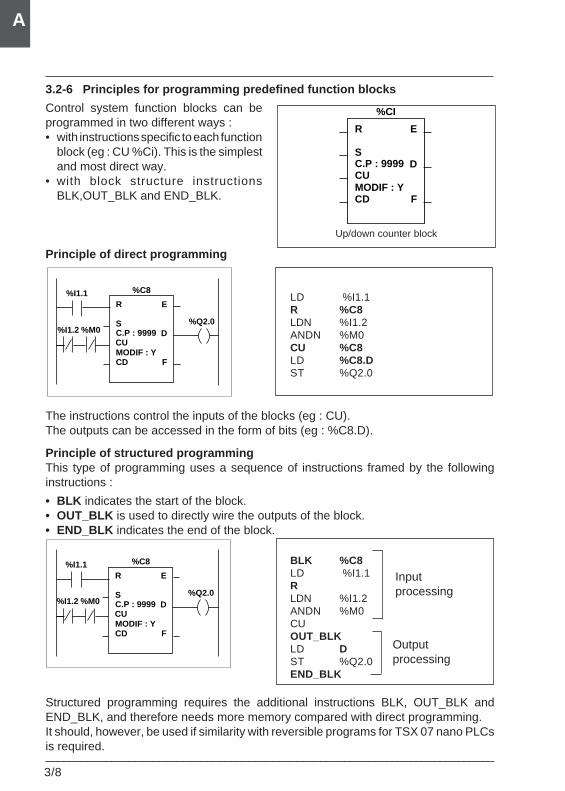
3/8___________________________________________________________________________
A
3.2-6 Principles for programming predefined function blocks
Control system function blocks can beprogrammed in two different ways :• with instructions specific to each function
block (eg : CU %Ci). This is the simplestand most direct way.
• with block structure instructionsBLK,OUT_BLK and END_BLK.
Principle of direct programming
LD %I1.1R %C8LDN %I1.2ANDN %M0CU %C8LD %C8.DST %Q2.0
The instructions control the inputs of the blocks (eg : CU).The outputs can be accessed in the form of bits (eg : %C8.D).
Principle of structured programmingThis type of programming uses a sequence of instructions framed by the followinginstructions :
• BLK indicates the start of the block.• OUT_BLK is used to directly wire the outputs of the block.• END_BLK indicates the end of the block.
BLK %C8LD %I1.1RLDN %I1.2ANDN %M0CUOUT_BLKLD DST %Q2.0END_BLK
Structured programming requires the additional instructions BLK, OUT_BLK andEND_BLK, and therefore needs more memory compared with direct programming.It should, however, be used if similarity with reversible programs for TSX 07 nano PLCsis required.
Up/down counter block
Inputprocessing
Outputprocessing
R
S
CU
CD F
D
E
%CI
C.P : 9999
MODIF : Y
%Q2.0
%I1.1
%I1.2
R
S
CU
CD F
D
E
%C8
C.P : 9999
MODIF : Y
%M0
%Q2.0
%I1.1
%I1.2
R
S
CU
CD F
D
E
%C8
C.P : 9999
MODIF : Y
%M0
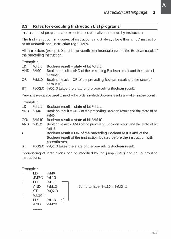
Instruction List language 3
___________________________________________________________________________3/9
A
3.3 Rules for executing Instruction List programs
Instruction list programs are executed sequentially instruction by instruction.
The first instruction in a series of instructions must always be either an LD instructionor an unconditional instruction (eg : JMP).
All instructions (except LD and the unconditional instructions) use the Boolean result ofthe preceding instruction.
Example :LD %I1.1 Boolean result = state of bit %I1.1.AND %M0 Boolean result = AND of the preceding Boolean result and the state of
bit %M0.OR %M10 Boolean result = OR of the preceding Boolean result and the state of
bit %M10.ST %Q2.0 %Q2.0 takes the state of the preceding Boolean result.
Parentheses can be used to modify the order in which Boolean results are taken into account :
Example :LD %I1.1 Boolean result = state of bit %I1.1.AND %M0 Boolean result = AND of the preceding Boolean result and the state of bit
%M0.OR( %M10 Boolean result = state of bit %M10.AND %I1.2 Boolean result = AND of the preceding Boolean result and the state of bit
%I1.2.) Boolean result = OR of the preceding Boolean result and of the
Boolean result of the instruction located before the instruction withparentheses.
ST %Q2.0 %Q2.0 takes the state of the preceding Boolean result.
Sequencing of instructions can be modified by the jump (JMP) and call subroutineinstructions.
Example :! LD %M0
JMPC %L10! LD %I1.1
AND %M10 Jump to label %L10 if %M0=1ST %Q2.0
! %L10 :LD %I1.3AND %M20.........

3/10___________________________________________________________________________
A
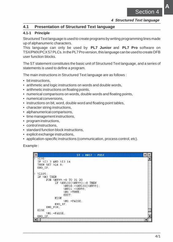
Structured Text language 4
___________________________________________________________________________4/1
A
4.1 Presentation of Structured Text language
4.1-1 Principle
Structured Text language is used to create programs by writing programming lines madeup of alphanumeric characters.This language can only be used by PL7 Junior and PL7 Pro software onTSX/PMX/PCX 57 PLCs. In the PL7 Pro version, this language can be used to create DFBuser function blocks.
The ST statement constitutes the basic unit of Structured Text language, and a series ofstatements is used to define a program.
The main instructions in Structured Text language are as follows :
• bit instructions,• arithmetic and logic instructions on words and double words,• arithmetic instructions on floating points,• numerical comparisons on words, double words and floating points,• numerical conversions,• instructions on bit, word, double word and floating point tables,• character string instructions,• alphanumerical comparisons,• time management instructions,• program instructions,• control instructions,• standard function block instructions,• explicit exchange instructions,• application-specific instructions (communication, process control, etc).
Example :
Section 44 Structured Text language

4/2___________________________________________________________________________
A
4.1-2 Instructions
Bit instructions
Description Function
:= Bit assignmentOR Boolean ORAND Boolean ANDXOR Exclusive Boolean ORNOT InversionRE Rising edgeFE Falling edge
SET Set to 1RESET Reset to 0
Numerical comparisons on words, double words and floating points
Description Function
< Strictly less than> Strictly greater than
<= Less than or equal to>= Greater than or equal to= Equal to
<> Different from
Bit tables
Description Function
Table := Table Assignment between two tablesTable := Word Assignment of a word to a tableWord := Table Assignment of a table to a word
Table := Double word Assignment of a double word to a tableDouble word := Table Assignment of a table to a double word
COPY_BIT Copy a bit table to a bit tableAND_ARX AND between two tablesOR_ARX OR between two tables
XOR_ARX Exclusive OR between two tablesNOT_ARX Negation on a table
BIT_W Copy a bit table to a word tableBIT_D Copy a bit table to a double word tableW_BIT Copy a word table to a bit tableD_BIT Copy a double word table to a bit table
LENGTH_ARX Calculate the length of a table in number of elements
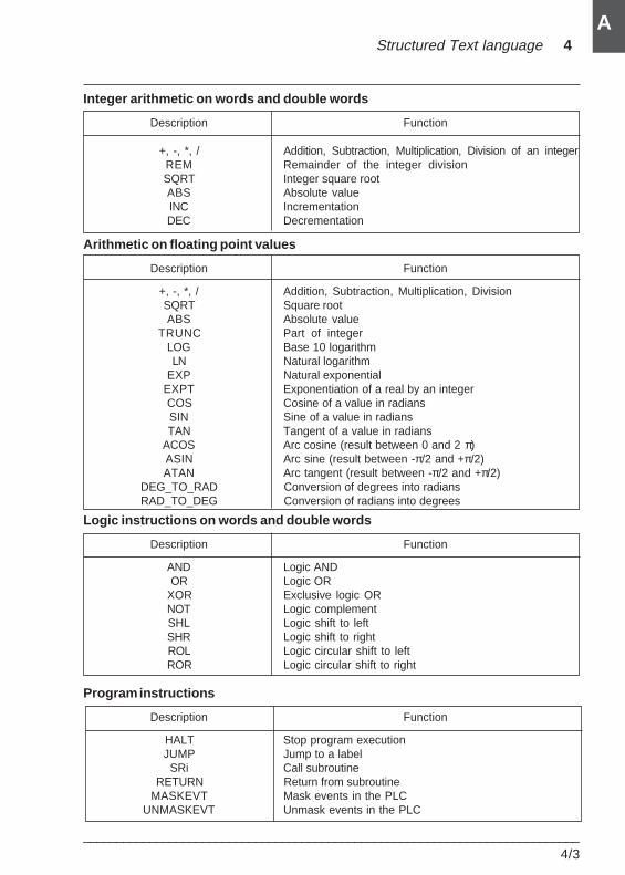
Structured Text language 4
___________________________________________________________________________4/3
A
Integer arithmetic on words and double words
Description Function
+, -, *, / Addition, Subtraction, Multiplication, Division of an integerREM Remainder of the integer divisionSQRT Integer square rootABS Absolute valueINC IncrementationDEC Decrementation
Arithmetic on floating point values
Description Function
+, -, *, / Addition, Subtraction, Multiplication, DivisionSQRT Square rootABS Absolute value
TRUNC Part of integerLOG Base 10 logarithmLN Natural logarithm
EXP Natural exponentialEXPT Exponentiation of a real by an integerCOS Cosine of a value in radiansSIN Sine of a value in radiansTAN Tangent of a value in radians
ACOS Arc cosine (result between 0 and 2 π)ASIN Arc sine (result between -π/2 and +π/2)ATAN Arc tangent (result between -π/2 and +π/2)
DEG_TO_RAD Conversion of degrees into radiansRAD_TO_DEG Conversion of radians into degrees
Logic instructions on words and double words
Description Function
AND Logic ANDOR Logic OR
XOR Exclusive logic ORNOT Logic complementSHL Logic shift to leftSHR Logic shift to rightROL Logic circular shift to leftROR Logic circular shift to right
Program instructions
Description Function
HALT Stop program executionJUMP Jump to a label
SRi Call subroutineRETURN Return from subroutine
MASKEVT Mask events in the PLCUNMASKEVT Unmask events in the PLC
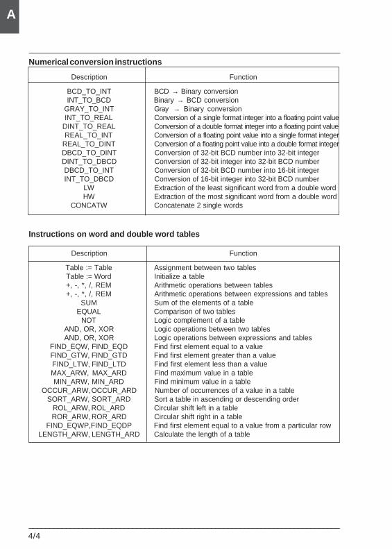
4/4___________________________________________________________________________
A
Numerical conversion instructions
Description Function
BCD_TO_INT BCD → Binary conversionINT_TO_BCD Binary → BCD conversion
GRAY_TO_INT Gray → Binary conversionINT_TO_REAL Conversion of a single format integer into a floating point value
DINT_TO_REAL Conversion of a double format integer into a floating point valueREAL_TO_INT Conversion of a floating point value into a single format integer
REAL_TO_DINT Conversion of a floating point value into a double format integerDBCD_TO_DINT Conversion of 32-bit BCD number into 32-bit integerDINT_TO_DBCD Conversion of 32-bit integer into 32-bit BCD numberDBCD_TO_INT Conversion of 32-bit BCD number into 16-bit integerINT_TO_DBCD Conversion of 16-bit integer into 32-bit BCD number
LW Extraction of the least significant word from a double wordHW Extraction of the most significant word from a double word
CONCATW Concatenate 2 single words
Instructions on word and double word tables
Description Function
Table := Table Assignment between two tablesTable := Word Initialize a table+, -, *, /, REM Arithmetic operations between tables+, -, *, /, REM Arithmetic operations between expressions and tables
SUM Sum of the elements of a tableEQUAL Comparison of two tables
NOT Logic complement of a tableAND, OR, XOR Logic operations between two tablesAND, OR, XOR Logic operations between expressions and tables
FIND_EQW, FIND_EQD Find first element equal to a valueFIND_GTW, FIND_GTD Find first element greater than a valueFIND_LTW, FIND_LTD Find first element less than a valueMAX_ARW, MAX_ARD Find maximum value in a tableMIN_ARW, MIN_ARD Find minimum value in a table
OCCUR_ARW, OCCUR_ARD Number of occurrences of a value in a tableSORT_ARW, SORT_ARD Sort a table in ascending or descending order
ROL_ARW, ROL_ARD Circular shift left in a tableROR_ARW, ROR_ARD Circular shift right in a table
FIND_EQWP,FIND_EQDP Find first element equal to a value from a particular rowLENGTH_ARW, LENGTH_ARD Calculate the length of a table
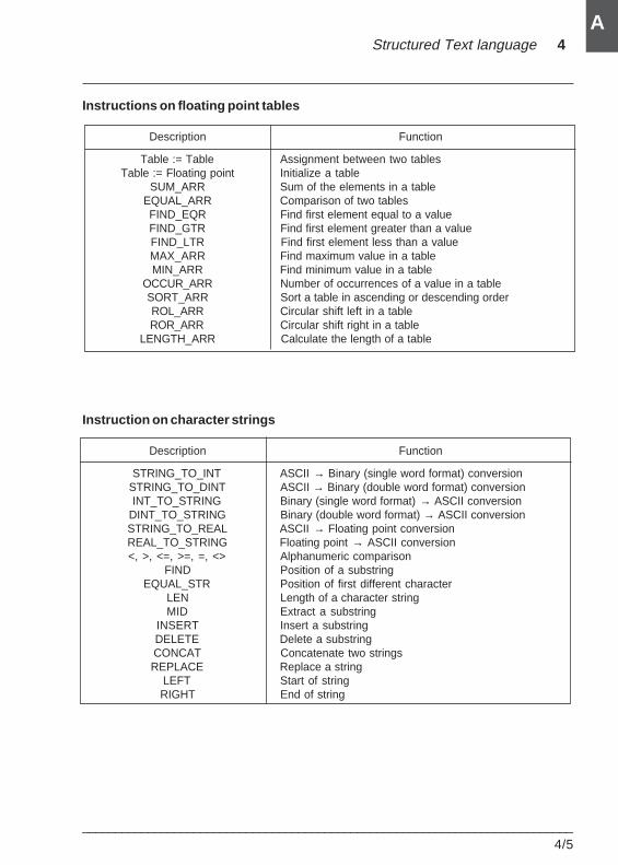
Structured Text language 4
___________________________________________________________________________4/5
A
Instructions on floating point tables
Description Function
Table := Table Assignment between two tablesTable := Floating point Initialize a table
SUM_ARR Sum of the elements in a tableEQUAL_ARR Comparison of two tablesFIND_EQR Find first element equal to a valueFIND_GTR Find first element greater than a valueFIND_LTR Find first element less than a valueMAX_ARR Find maximum value in a tableMIN_ARR Find minimum value in a table
OCCUR_ARR Number of occurrences of a value in a tableSORT_ARR Sort a table in ascending or descending orderROL_ARR Circular shift left in a tableROR_ARR Circular shift right in a table
LENGTH_ARR Calculate the length of a table
Instruction on character strings
Description Function
STRING_TO_INT ASCII → Binary (single word format) conversionSTRING_TO_DINT ASCII → Binary (double word format) conversionINT_TO_STRING Binary (single word format) → ASCII conversion
DINT_TO_STRING Binary (double word format) → ASCII conversionSTRING_TO_REAL ASCII → Floating point conversionREAL_TO_STRING Floating point → ASCII conversion<, >, <=, >=, =, <> Alphanumeric comparison
FIND Position of a substringEQUAL_STR Position of first different character
LEN Length of a character stringMID Extract a substring
INSERT Insert a substringDELETE Delete a substringCONCAT Concatenate two stringsREPLACE Replace a string
LEFT Start of stringRIGHT End of string
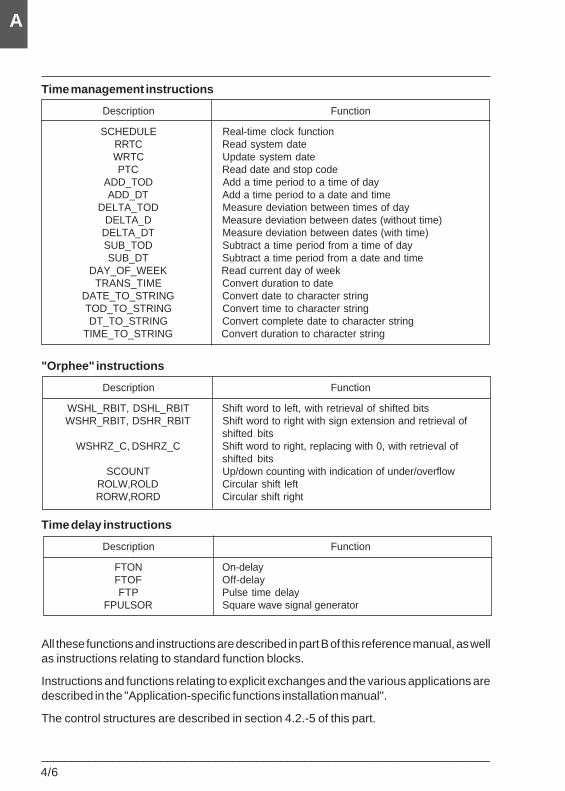
4/6___________________________________________________________________________
A
Time management instructions
Description Function
SCHEDULE Real-time clock functionRRTC Read system dateWRTC Update system datePTC Read date and stop code
ADD_TOD Add a time period to a time of dayADD_DT Add a time period to a date and time
DELTA_TOD Measure deviation between times of dayDELTA_D Measure deviation between dates (without time)
DELTA_DT Measure deviation between dates (with time)SUB_TOD Subtract a time period from a time of daySUB_DT Subtract a time period from a date and time
DAY_OF_WEEK Read current day of weekTRANS_TIME Convert duration to date
DATE_TO_STRING Convert date to character stringTOD_TO_STRING Convert time to character stringDT_TO_STRING Convert complete date to character string
TIME_TO_STRING Convert duration to character string
"Orphee" instructions
Description Function
WSHL_RBIT, DSHL_RBIT Shift word to left, with retrieval of shifted bitsWSHR_RBIT, DSHR_RBIT Shift word to right with sign extension and retrieval of
shifted bitsWSHRZ_C, DSHRZ_C Shift word to right, replacing with 0, with retrieval of
shifted bitsSCOUNT Up/down counting with indication of under/overflow
ROLW,ROLD Circular shift leftRORW,RORD Circular shift right
Time delay instructions
Description Function
FTON On-delayFTOF Off-delayFTP Pulse time delay
FPULSOR Square wave signal generator
All these functions and instructions are described in part B of this reference manual, as wellas instructions relating to standard function blocks.
Instructions and functions relating to explicit exchanges and the various applications aredescribed in the "Application-specific functions installation manual".
The control structures are described in section 4.2.-5 of this part.
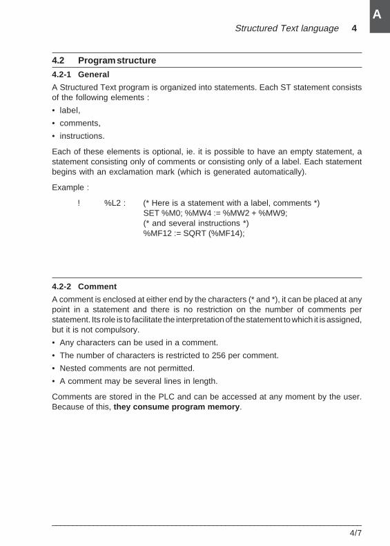
Structured Text language 4
___________________________________________________________________________4/7
A
4.2 Program structure
4.2-1 General
A Structured Text program is organized into statements. Each ST statement consistsof the following elements :
• label,
• comments,
• instructions.
Each of these elements is optional, ie. it is possible to have an empty statement, astatement consisting only of comments or consisting only of a label. Each statementbegins with an exclamation mark (which is generated automatically).
Example :
! %L2 : (* Here is a statement with a label, comments *)SET %M0; %MW4 := %MW2 + %MW9;(* and several instructions *)%MF12 := SQRT (%MF14);
4.2-2 Comment
A comment is enclosed at either end by the characters (* and *), it can be placed at anypoint in a statement and there is no restriction on the number of comments perstatement. Its role is to facilitate the interpretation of the statement to which it is assigned,but it is not compulsory.
• Any characters can be used in a comment.
• The number of characters is restricted to 256 per comment.
• Nested comments are not permitted.
• A comment may be several lines in length.
Comments are stored in the PLC and can be accessed at any moment by the user.Because of this, they consume program memory .
4/8___________________________________________________________________________
A
4.2-3 Label
A label is used to reference a statement in a program entity (main program, subroutine,etc) but is not compulsory.
This label has the following syntax : %Li where i is between 0 and 999 and is locatedat the beginning of the statement. A label reference can only be assigned to a singlestatement within the same program entity (SR, Main, Program module).
On the other hand, a statement must be refenced in order to allow connection after aprogram jump.
The label references can be in any order; it is the order in which the statements areentered which is taken into account by the system during the scan.
4.2-4 Instructions
The program is made up of instructions. An ST statement can contain severalinstructions. Each instruction must end with the character ';'.
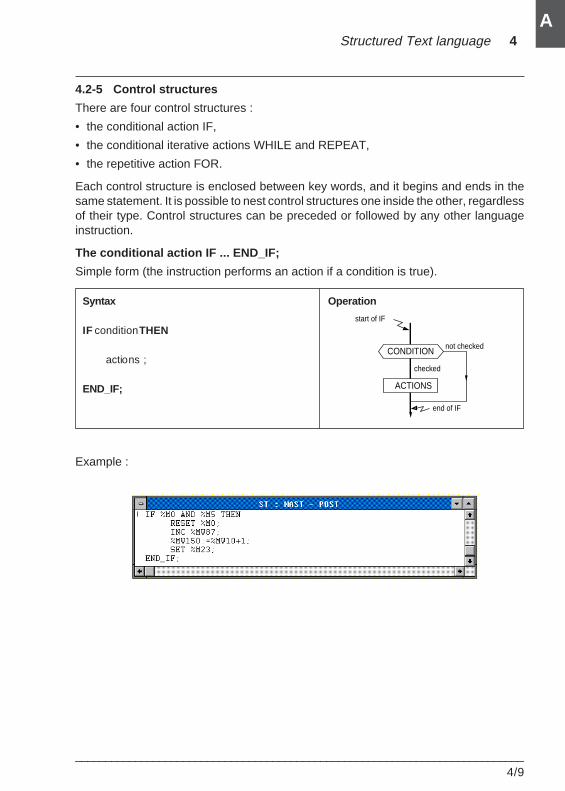
Structured Text language 4
___________________________________________________________________________4/9
A
4.2-5 Control structures
There are four control structures :
• the conditional action IF,
• the conditional iterative actions WHILE and REPEAT,
• the repetitive action FOR.
Each control structure is enclosed between key words, and it begins and ends in thesame statement. It is possible to nest control structures one inside the other, regardlessof their type. Control structures can be preceded or followed by any other languageinstruction.
The conditional action IF ... END_IF;
Simple form (the instruction performs an action if a condition is true).
Example :
Syntax Operation
IF condition THEN
actions ;
END_IF;
CONDITION
ACTIONS
start of IF
end of IF
checked
not checked
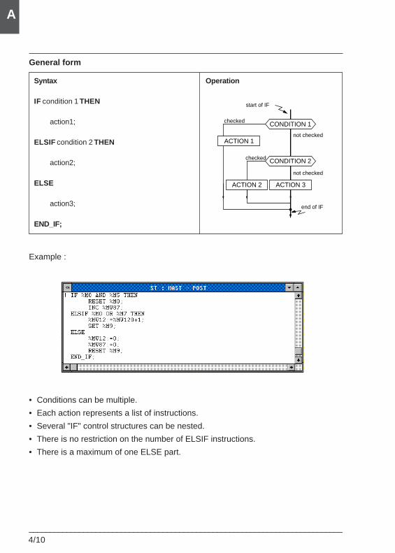
4/10___________________________________________________________________________
A
General form
Example :
• Conditions can be multiple.
• Each action represents a list of instructions.
• Several "IF" control structures can be nested.
• There is no restriction on the number of ELSIF instructions.
• There is a maximum of one ELSE part.
Syntax Operation
IF condition 1 THEN
action1;
ELSIF condition 2 THEN
action2;
ELSE
action3;
END_IF;
CONDITION 2
CONDITION 1
ACTION 3
start of IF
end of IF
not checked
not checked
checked
checked
ACTION 2
ACTION 1
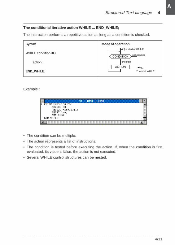
Structured Text language 4
___________________________________________________________________________4/11
A
The conditional iterative action WHILE ... END_WHILE;
The instruction performs a repetitive action as long as a condition is checked.
Example :
Syntax Mode of operation
WHILE condition DO
action;
END_WHILE;
CONDITION
ACTION
end of WHILE
start of WHILE
checked
not checked
• The condition can be multiple.
• The action represents a list of instructions.
• The condition is tested before executing the action. If, when the condition is firstevaluated, its value is false, the action is not executed.
• Several WHILE control structures can be nested.
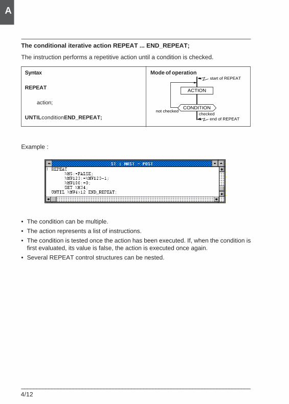
4/12___________________________________________________________________________
A
The conditional iterative action REPEAT ... END_REPEAT;
The instruction performs a repetitive action until a condition is checked.
Example :
• The condition can be multiple.
• The action represents a list of instructions.
• The condition is tested once the action has been executed. If, when the condition isfirst evaluated, its value is false, the action is executed once again.
• Several REPEAT control structures can be nested.
Syntax Mode of operation
REPEAT
action;
UNTIL condition END_REPEAT;
CONDITION
ACTION
end of REPEAT
start of REPEAT
checkednot checked
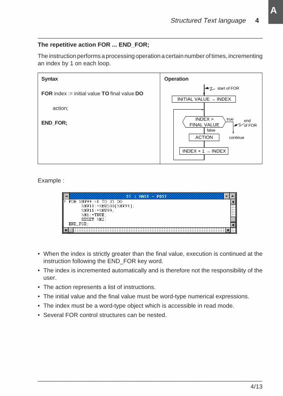
Structured Text language 4
___________________________________________________________________________4/13
A
The repetitive action FOR ... END_FOR;
The instruction performs a processing operation a certain number of times, incrementingan index by 1 on each loop.
Example :
• When the index is strictly greater than the final value, execution is continued at theinstruction following the END_FOR key word.
• The index is incremented automatically and is therefore not the responsibility of theuser.
• The action represents a list of instructions.
• The initial value and the final value must be word-type numerical expressions.
• The index must be a word-type object which is accessible in read mode.
• Several FOR control structures can be nested.
Syntax Operation
FOR index := initial value TO final value DO
action;
END_FOR;INDEX >
FINAL VALUE
ACTION
INDEX + 1 → INDEX
INITIAL VALUE → INDEX
endof FOR
start of FOR
true
false
continue
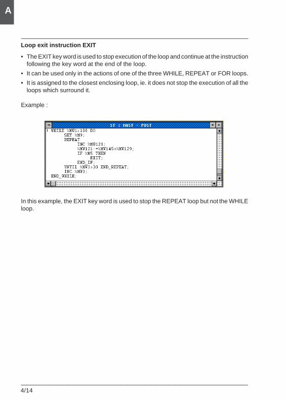
4/14___________________________________________________________________________
A
Loop exit instruction EXIT
• The EXIT key word is used to stop execution of the loop and continue at the instructionfollowing the key word at the end of the loop.
• It can be used only in the actions of one of the three WHILE, REPEAT or FOR loops.
• It is assigned to the closest enclosing loop, ie. it does not stop the execution of all theloops which surround it.
Example :
In this example, the EXIT key word is used to stop the REPEAT loop but not the WHILEloop.
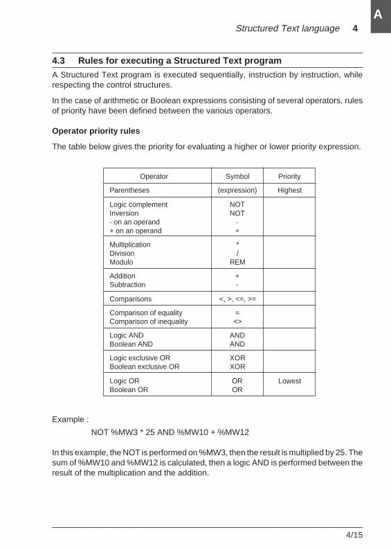
Structured Text language 4
___________________________________________________________________________4/15
A
4.3 Rules for executing a Structured Text program
A Structured Text program is executed sequentially, instruction by instruction, whilerespecting the control structures.
In the case of arithmetic or Boolean expressions consisting of several operators, rulesof priority have been defined between the various operators.
Operator priority rules
The table below gives the priority for evaluating a higher or lower priority expression.
Operator Symbol Priority
Parentheses (expression) Highest
Logic complement NOTInversion NOT- on an operand -+ on an operand +
Multiplication *Division /Modulo REM
Addition +Subtraction -
Comparisons <, >, <=, >=
Comparison of equality =Comparison of inequality <>
Logic AND ANDBoolean AND AND
Logic exclusive OR XORBoolean exclusive OR XOR
Logic OR OR LowestBoolean OR OR
Example :
NOT %MW3 * 25 AND %MW10 + %MW12
In this example, the NOT is performed on %MW3, then the result is multiplied by 25. Thesum of %MW10 and %MW12 is calculated, then a logic AND is performed between theresult of the multiplication and the addition.
4/16___________________________________________________________________________
A
When there is conflict between two operators of the same priority, the first operator willtake precedence (evaluation is performed from left to right).
Example :
%MW34 * 2 REM 6
In this example, %MW34 is first multiplied by 2, then the result is used toperform the modulo.
Use of parentheses
Parentheses are used to modify the order in which operators are evaluated, for exampleto give an addition higher priority than a multiplication.
Example :
(%MW10 + %MW11) * %MW12
In this example, the addition will be performed before the multiplication.
Parentheses can be nested; there is no limit to the levels of nesting.
Parentheses can also be used to avoid incorrect interpretation of the program.
Example :
NOT %MW2 <> %MW4 + %MW6
By using operator priority rules, the following interpretation is obtained :
((NOT %MW2) <> (%MW4 + %MW6))
The user might well try to perform the following operation :
NOT (%MW2 <> (%MW4 + %MW6))
This example shows that parentheses can be used to clarify the program.
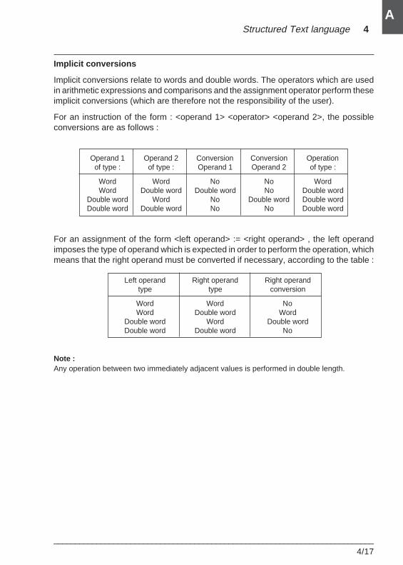
Structured Text language 4
___________________________________________________________________________4/17
A
Implicit conversions
Implicit conversions relate to words and double words. The operators which are usedin arithmetic expressions and comparisons and the assignment operator perform theseimplicit conversions (which are therefore not the responsibility of the user).
For an instruction of the form : <operand 1> <operator> <operand 2>, the possibleconversions are as follows :
Operand 1 Operand 2 Conversion Conversion Operationof type : of type : Operand 1 Operand 2 of type :
Word Word No No WordWord Double word Double word No Double word
Double word Word No Double word Double wordDouble word Double word No No Double word
For an assignment of the form <left operand> := <right operand> , the left operandimposes the type of operand which is expected in order to perform the operation, whichmeans that the right operand must be converted if necessary, according to the table :
Left operand Right operand Right operandtype type conversion
Word Word NoWord Double word Word
Double word Word Double wordDouble word Double word No
Note :Any operation between two immediately adjacent values is performed in double length.

4/18___________________________________________________________________________
A
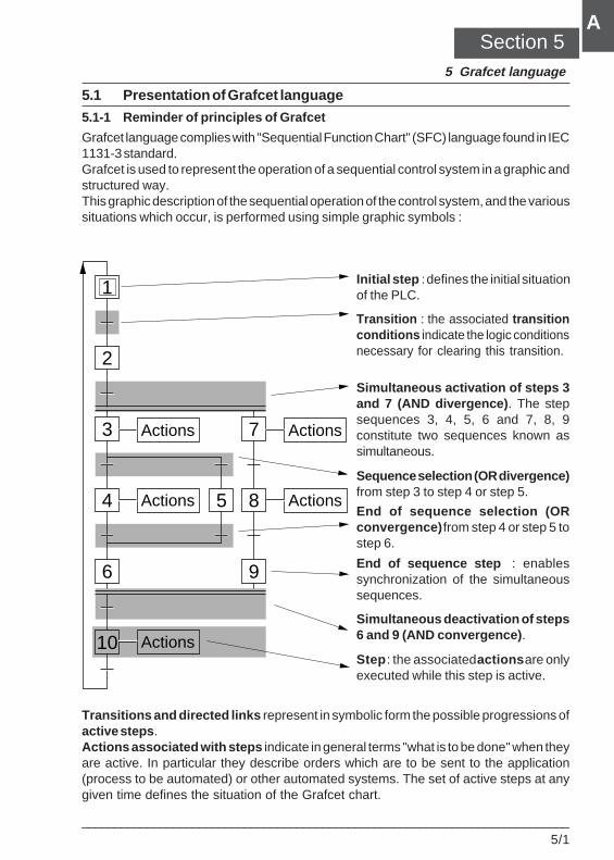
Grafcet language 5
___________________________________________________________________________5/1
A
5.1 Presentation of Grafcet language
5.1-1 Reminder of principles of Grafcet
Grafcet language complies with "Sequential Function Chart" (SFC) language found in IEC1131-3 standard.Grafcet is used to represent the operation of a sequential control system in a graphic andstructured way.This graphic description of the sequential operation of the control system, and the varioussituations which occur, is performed using simple graphic symbols :
Initial step : defines the initial situationof the PLC.
Transition : the associated transitionconditions indicate the logic conditionsnecessary for clearing this transition.
Simultaneous activation of steps 3and 7 (AND divergence) . The stepsequences 3, 4, 5, 6 and 7, 8, 9constitute two sequences known assimultaneous.
Sequence selection (OR divergence)from step 3 to step 4 or step 5.
End of sequence selection (ORconvergence) from step 4 or step 5 tostep 6.
End of sequence step : enablessynchronization of the simultaneoussequences.
Simultaneous deactivation of steps6 and 9 (AND convergence) .
Step : the associated actions are onlyexecuted while this step is active.
Transitions and directed links represent in symbolic form the possible progressions ofactive steps .Actions associated with steps indicate in general terms "what is to be done" when theyare active. In particular they describe orders which are to be sent to the application(process to be automated) or other automated systems. The set of active steps at anygiven time defines the situation of the Grafcet chart.
Section 55 Grafcet language
1
2
3
4
6
10 Actions
Actions Actions
Actions 7 Actions
85
9
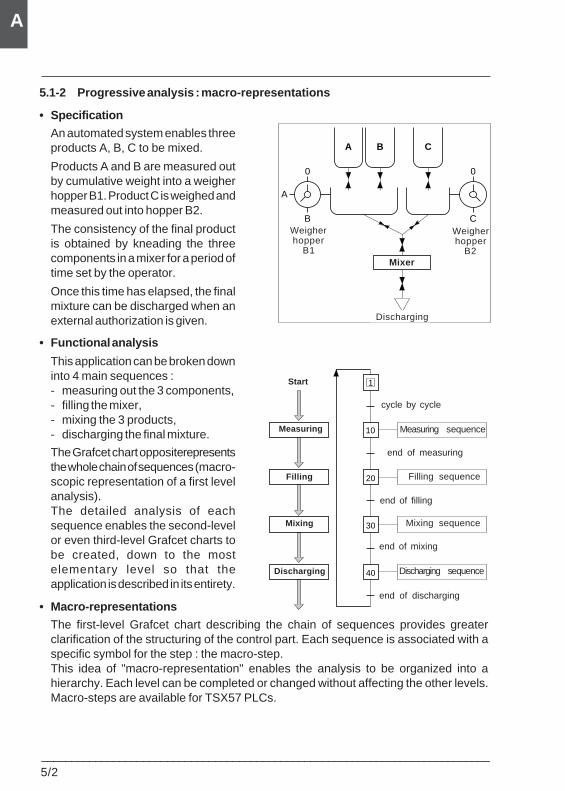
5/2___________________________________________________________________________
A
5.1-2 Progressive analysis : macro-representations
• Specification
An automated system enables threeproducts A, B, C to be mixed.
Products A and B are measured outby cumulative weight into a weigherhopper B1. Product C is weighed andmeasured out into hopper B2.
The consistency of the final productis obtained by kneading the threecomponents in a mixer for a period oftime set by the operator.
Once this time has elapsed, the finalmixture can be discharged when anexternal authorization is given.
• Functional analysis
This application can be broken downinto 4 main sequences :- measuring out the 3 components,- filling the mixer,- mixing the 3 products,- discharging the final mixture.
The Grafcet chart opposite representsthe whole chain of sequences (macro-scopic representation of a first levelanalysis).The detailed analysis of eachsequence enables the second-levelor even third-level Grafcet charts tobe created, down to the mostelementary level so that theapplication is described in its entirety.
• Macro-representations
The first-level Grafcet chart describing the chain of sequences provides greaterclarification of the structuring of the control part. Each sequence is associated with aspecific symbol for the step : the macro-step.This idea of "macro-representation" enables the analysis to be organized into ahierarchy. Each level can be completed or changed without affecting the other levels.Macro-steps are available for TSX57 PLCs.
0
C
0
A
B
Mélangeur
A B C
Tremiepeseuse
B2
Tremiepeseuse
B1
Evacuation
10
20
30
40
Séquence RemplissageRemplissage
Séquence DosageDosage
Séquence MélangeMélange
Séquence EvacuationEvacuation
1
cycle par cycle
fin de dosage
fin de remplissage
fin de mélange
fin d'évacuation
Début
Mixer
Discharging
Weigherhopper
B1
Weigherhopper
B2
Start
Measuring
Filling
Mixing
Discharging
cycle by cycle
Measuring sequence
end of measuring
Filling sequence
end of filling
Mixing sequence
end of mixing
Discharging sequence
end of discharging
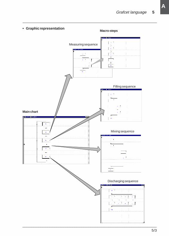
Grafcet language 5
___________________________________________________________________________5/3
A
Filling sequence
Mixing sequence
Discharging sequence
Measuring sequence
Macro-steps
Main chart
• Graphic representation
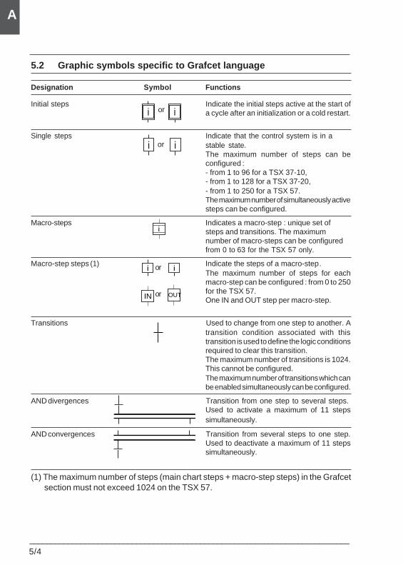
5/4___________________________________________________________________________
A
5.2 Graphic symbols specific to Grafcet language
Designation Symbol Functions
Initial steps Indicate the initial steps active at the start ofa cycle after an initialization or a cold restart.
Single steps Indicate that the control system is in astable state.The maximum number of steps can beconfigured :- from 1 to 96 for a TSX 37-10,- from 1 to 128 for a TSX 37-20,- from 1 to 250 for a TSX 57.The maximum number of simultaneously activesteps can be configured.
Macro-steps Indicates a macro-step : unique set ofsteps and transitions. The maximumnumber of macro-steps can be configuredfrom 0 to 63 for the TSX 57 only.
Macro-step steps (1) Indicate the steps of a macro-step.The maximum number of steps for eachmacro-step can be configured : from 0 to 250for the TSX 57.One IN and OUT step per macro-step.
Transitions Used to change from one step to another. Atransition condition associated with thistransition is used to define the logic conditionsrequired to clear this transition.The maximum number of transitions is 1024.This cannot be configured.The maximum number of transitions which canbe enabled simultaneously can be configured.
AND divergences Transition from one step to several steps. Used to activate a maximum of 11 stepssimultaneously.
AND convergences Transition from several steps to one step.Used to deactivate a maximum of 11 stepssimultaneously.
(1) The maximum number of steps (main chart steps + macro-step steps) in the Grafcetsection must not exceed 1024 on the TSX 57.
i ou ior
i ou ior
i ou i
i
IN OUTor
or
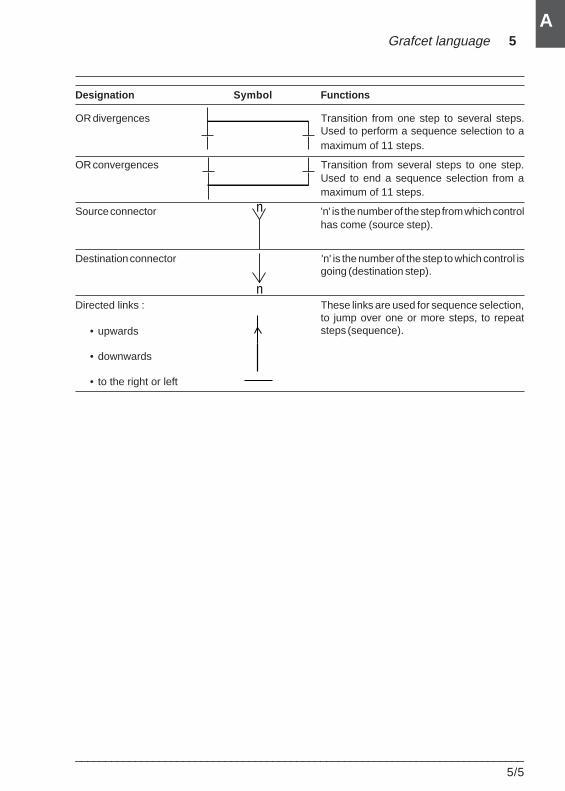
Grafcet language 5
___________________________________________________________________________5/5
A
n
n
• upwards
• downwards
• to the right or left
Designation Symbol Functions
OR divergences Transition from one step to several steps.Used to perform a sequence selection to amaximum of 11 steps.
OR convergences Transition from several steps to one step.Used to end a sequence selection from amaximum of 11 steps.
Source connector 'n' is the number of the step from which controlhas come (source step).
Destination connector 'n' is the number of the step to which control isgoing (destination step).
Directed links : These links are used for sequence selection,to jump over one or more steps, to repeatsteps (sequence).
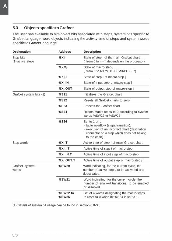
5/6___________________________________________________________________________
A
5.3 Objects specific to Grafcet
The user has available to him object bits associated with steps, system bits specific toGrafcet language, word objects indicating the activity time of steps and system wordsspecific to Grafcet language.
Designation Address Description
Step bits %Xi State of step i of the main Grafcet chart(1=active step) (i from 0 to n) (n depends on the processor)
%XMj State of macro-step j(j from 0 to 63 for TSX/PMX/PCX 57)
%Xj.i State of step i of macro-step j
%Xj.IN State of input step of macro-step j
%Xj.OUT State of output step of macro-step j
Grafcet system bits (1) %S21 Initializes the Grafcet chart
%S22 Resets all Grafcet charts to zero
%S23 Freezes the Grafcet chart
%S24 Resets macro-steps to 0 according to systemwords %SW22 to %SW25
%S26 Set to 1 on :- table overflow (steps/transition),- execution of an incorrect chart (destination
connector on a step which does not belongto the chart).
Step words %Xi.T Active time of step i of main Grafcet chart
%Xj.i.T Active time of step i of macro-step j
%Xj.IN.T Active time of input step of macro-step j
%Xj.OUT.T Active time of output step of macro-step j
Grafcet system %SW20 Word indicating, for the current cycle, thewords number of active steps, to be activated and
deactivated.
%SW21 Word indicating, for the current cycle, thenumber of enabled transitions, to be enabledor disabled.
%SW22 to Set of 4 words designating the macro-steps%SW25 to reset to 0 when bit %S24 is set to 1.
(1) Details of system bit usage can be found in section 6.8-3.
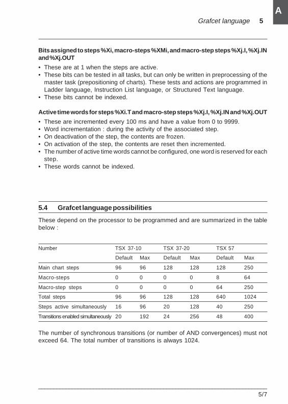
Grafcet language 5
___________________________________________________________________________5/7
A
Bits assigned to steps %Xi, macro-steps %XMi, and macro-step steps %Xj.I, %Xj.INand %Xj.OUT
• These are at 1 when the steps are active.• These bits can be tested in all tasks, but can only be written in preprocessing of the
master task (prepositioning of charts). These tests and actions are programmed inLadder language, Instruction List language, or Structured Text language.
• These bits cannot be indexed.
Active time words for steps %Xi.T and macro-step steps %Xj.I, %Xj.IN and %Xj.OUT
• These are incremented every 100 ms and have a value from 0 to 9999.• Word incrementation : during the activity of the associated step.• On deactivation of the step, the contents are frozen.• On activation of the step, the contents are reset then incremented.• The number of active time words cannot be configured, one word is reserved for each
step.• These words cannot be indexed.
5.4 Grafcet language possibilities
These depend on the processor to be programmed and are summarized in the tablebelow :
Number TSX 37-10 TSX 37-20 TSX 57
Default Max Default Max Default Max
Main chart steps 96 96 128 128 128 250
Macro-steps 0 0 0 0 8 64
Macro-step steps 0 0 0 0 64 250
Total steps 96 96 128 128 640 1024
Steps active simultaneously 16 96 20 128 40 250
Transitions enabled simultaneously 20 192 24 256 48 400
The number of synchronous transitions (or number of AND convergences) must notexceed 64. The total number of transitions is always 1024.
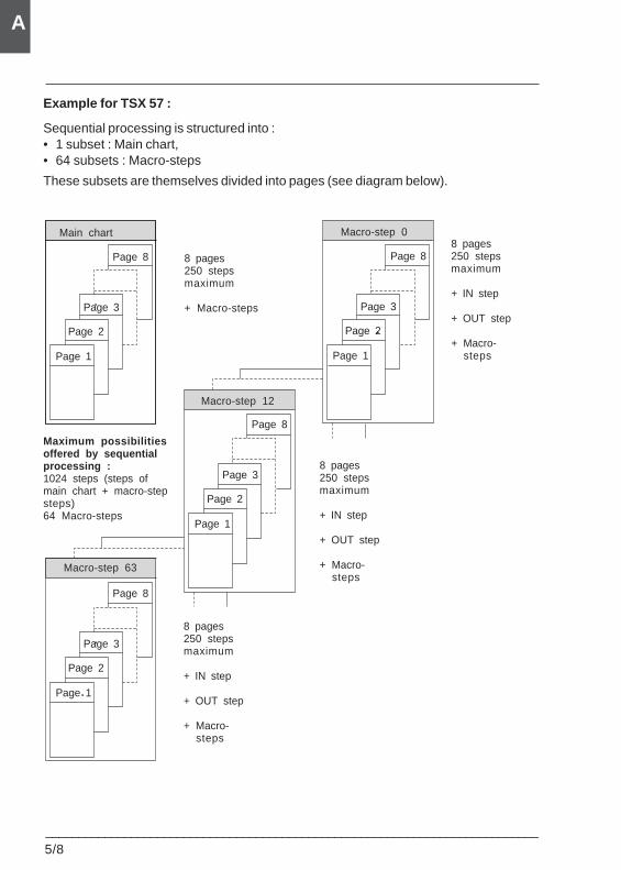
5/8___________________________________________________________________________
A
Example for TSX 57 :
Sequential processing is structured into :• 1 subset : Main chart,• 64 subsets : Macro-steps
These subsets are themselves divided into pages (see diagram below).
Main chart Macro-step 0
Macro-step 12
Macro-step 63
Page 1
Page 2
Page 3
Page 8
Page 1
Page 2
Page 3
Page 8
Page 1
Page 2
Page 3
Page 8
Page 1
Page 2
Page 3
Page 8
8 pages250 stepsmaximum
+ Macro-steps
Maximum possibilitiesoffered by sequentialprocessing :1024 steps (steps ofmain chart + macro-stepsteps)64 Macro-steps
8 pages250 stepsmaximum
+ IN step
+ OUT step
+ Macro-steps
8 pages250 stepsmaximum
+ IN step
+ OUT step
+ Macro-steps
8 pages250 stepsmaximum
+ IN step
+ OUT step
+ Macro-steps
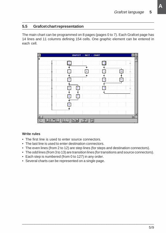
Grafcet language 5
___________________________________________________________________________5/9
A
5.5 Grafcet chart representation
The main chart can be programmed on 8 pages (pages 0 to 7). Each Grafcet page has14 lines and 11 columns defining 154 cells. One graphic element can be entered ineach cell.
Write rules
• The first line is used to enter source connectors.• The last line is used to enter destination connectors.• The even lines (from 2 to 12) are step lines (for steps and destination connectors).• The odd lines (from 3 to 13) are transition lines (for transitions and source connectors).• Each step is numbered (from 0 to 127) in any order.• Several charts can be represented on a single page.
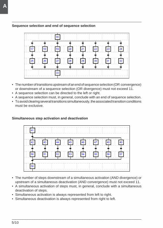
5/10___________________________________________________________________________
A
Sequence selection and end of sequence selection
• The number of transitions upstream of an end of sequence selection (OR convergence)or downstream of a sequence selection (OR divergence) must not exceed 11.
• A sequence selection can be directed to the left or right.• A sequence selection must, in general, conclude with an end of sequence selection.• To avoid clearing several transitions simultaneously, the associated transition conditions
must be exclusive.
Simultaneous step activation and deactivation
• The number of steps downstream of a simultaneous activation (AND divergence) orupstream of a simultaneous deactivation (AND convergence) must not exceed 11.
• A simultaneous activation of steps must, in general, conclude with a simultaneousdeactivation of steps.
• Simultaneous activation is always represented from left to right.• Simultaneous deactivation is always represented from right to left.
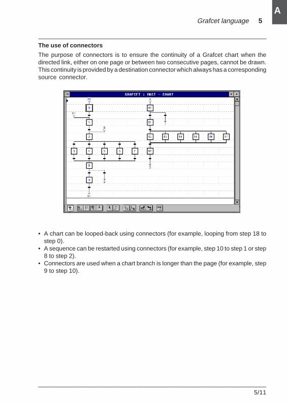
Grafcet language 5
___________________________________________________________________________5/11
A
The use of connectors
The purpose of connectors is to ensure the continuity of a Grafcet chart when thedirected link, either on one page or between two consecutive pages, cannot be drawn.This continuity is provided by a destination connector which always has a correspondingsource connector.
• A chart can be looped-back using connectors (for example, looping from step 18 tostep 0).
• A sequence can be restarted using connectors (for example, step 10 to step 1 or step8 to step 2).
• Connectors are used when a chart branch is longer than the page (for example, step9 to step 10).
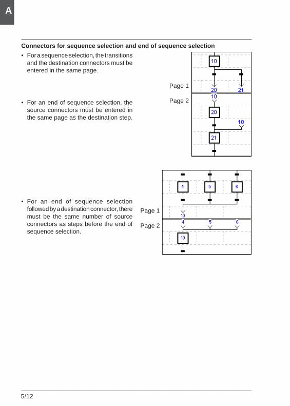
5/12___________________________________________________________________________
A
Connectors for sequence selection and end of sequence selection
• For a sequence selection, the transitionsand the destination connectors must beentered in the same page.
• For an end of sequence selection, thesource connectors must be entered inthe same page as the destination step.
• For an end of sequence selectionfollowed by a destination connector, theremust be the same number of sourceconnectors as steps before the end ofsequence selection.
Page 1
Page 2
Page 1
Page 2
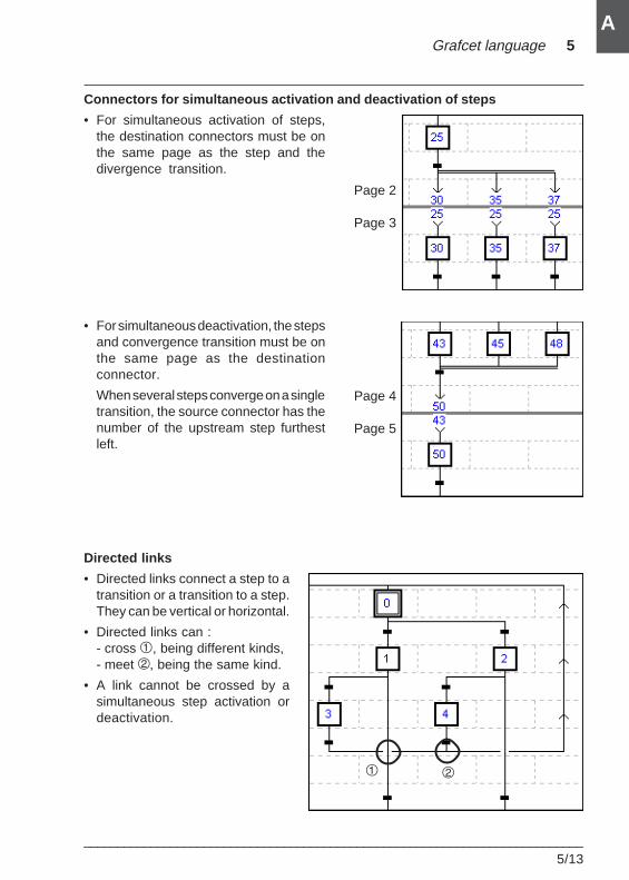
Grafcet language 5
___________________________________________________________________________5/13
A
Connectors for simultaneous activation and deactivation of steps
• For simultaneous activation of steps,the destination connectors must be onthe same page as the step and thedivergence transition.
• For simultaneous deactivation, the stepsand convergence transition must be onthe same page as the destinationconnector.
When several steps converge on a singletransition, the source connector has thenumber of the upstream step furthestleft.
Directed links
• Directed links connect a step to atransition or a transition to a step.They can be vertical or horizontal.
• Directed links can :- cross 1, being different kinds,- meet 2, being the same kind.
• A link cannot be crossed by asimultaneous step activation ordeactivation.
Page 2
Page 3
Page 4
Page 5
1 2
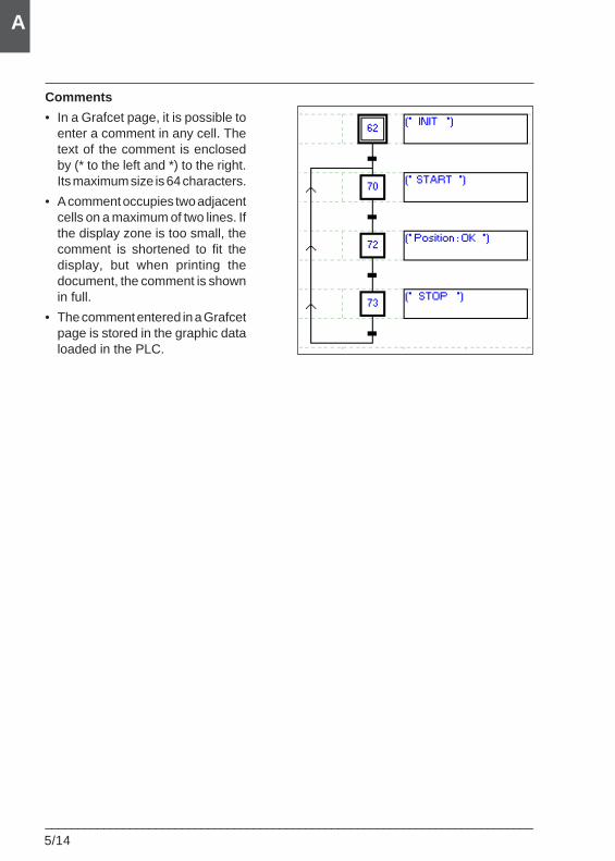
5/14___________________________________________________________________________
A
Comments
• In a Grafcet page, it is possible toenter a comment in any cell. Thetext of the comment is enclosedby (* to the left and *) to the right.Its maximum size is 64 characters.
• A comment occupies two adjacentcells on a maximum of two lines. Ifthe display zone is too small, thecomment is shortened to fit thedisplay, but when printing thedocument, the comment is shownin full.
• The comment entered in a Grafcetpage is stored in the graphic dataloaded in the PLC.
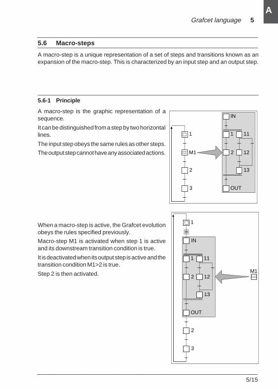
Grafcet language 5
___________________________________________________________________________5/15
A
5.6 Macro-steps
A macro-step is a unique representation of a set of steps and transitions known as anexpansion of the macro-step. This is characterized by an input step and an output step.
5.6-1 Principle
A macro-step is the graphic representation of asequence.
It can be distinguished from a step by two horizontallines.
The input step obeys the same rules as other steps.
The output step cannot have any associated actions.
When a macro-step is active, the Grafcet evolutionobeys the rules specified previously.
Macro-step M1 is activated when step 1 is activeand its downstream transition condition is true.
It is deactivated when its output step is active and thetransition condition M1>2 is true.
Step 2 is then activated.
IN
1 11
2 12
13
OUT
1
M1
2
3
IN
1 11
2 12
13
OUT
2
3
1
M1
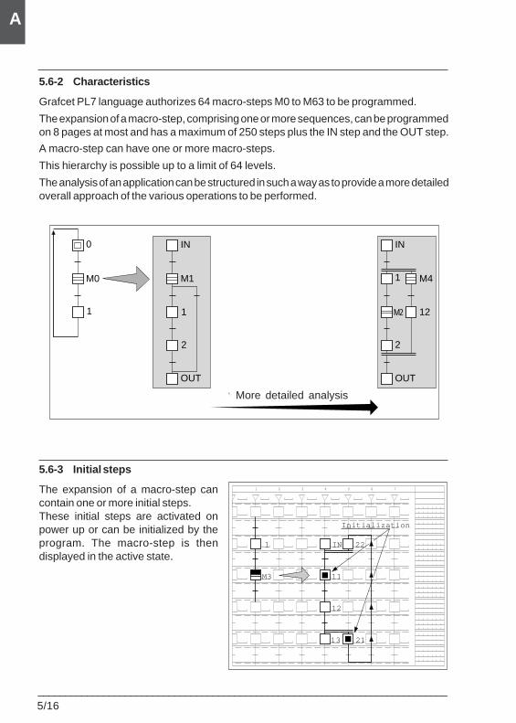
5/16___________________________________________________________________________
A
5.6-2 Characteristics
Grafcet PL7 language authorizes 64 macro-steps M0 to M63 to be programmed.
The expansion of a macro-step, comprising one or more sequences, can be programmedon 8 pages at most and has a maximum of 250 steps plus the IN step and the OUT step.
A macro-step can have one or more macro-steps.
This hierarchy is possible up to a limit of 64 levels.
The analysis of an application can be structured in such a way as to provide a more detailedoverall approach of the various operations to be performed.
5.6-3 Initial steps
The expansion of a macro-step cancontain one or more initial steps.These initial steps are activated onpower up or can be initialized by theprogram. The macro-step is thendisplayed in the active state.
0
M0
1
2
IN
1
OUT
M1
Vers une analyse détaillée
IN
1
12
OUT
2
M4
M2
More detailed analysis
1 2 3 4 5 6 7
IN1
12
22
M3
13
11
21
Initialization
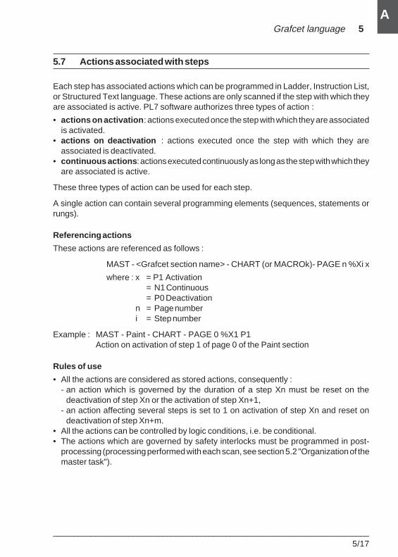
Grafcet language 5
___________________________________________________________________________5/17
A
5.7 Actions associated with steps
Each step has associated actions which can be programmed in Ladder, Instruction List,or Structured Text language. These actions are only scanned if the step with which theyare associated is active. PL7 software authorizes three types of action :
• actions on activation : actions executed once the step with which they are associatedis activated.
• actions on deactivation : actions executed once the step with which they areassociated is deactivated.
• continuous actions : actions executed continuously as long as the step with which theyare associated is active.
These three types of action can be used for each step.
A single action can contain several programming elements (sequences, statements orrungs).
Referencing actions
These actions are referenced as follows :
MAST - <Grafcet section name> - CHART (or MACROk)- PAGE n %Xi x
where : x = P1 Activation= N1 Continuous= P0 Deactivation
n = Page numberi = Step number
Example : MAST - Paint - CHART - PAGE 0 %X1 P1Action on activation of step 1 of page 0 of the Paint section
Rules of use
• All the actions are considered as stored actions, consequently :- an action which is governed by the duration of a step Xn must be reset on the
deactivation of step Xn or the activation of step Xn+1,- an action affecting several steps is set to 1 on activation of step Xn and reset on
deactivation of step Xn+m.• All the actions can be controlled by logic conditions, i.e. be conditional.• The actions which are governed by safety interlocks must be programmed in post-
processing (processing performed with each scan, see section 5.2 "Organization of themaster task").
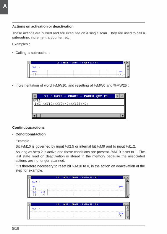
5/18___________________________________________________________________________
A
Actions on activation or deactivation
These actions are pulsed and are executed on a single scan. They are used to call asubroutine, increment a counter, etc.
Examples :
• Calling a subroutine :
• Incrementation of word %MW10, and resetting of %MW0 and %MW25 :
Continuous actions
• Conditional action
Example :
Bit %M10 is governed by input %I2.5 or internal bit %M9 and to input %I1.2.
As long as step 2 is active and these conditions are present, %M10 is set to 1. Thelast state read on deactivation is stored in the memory because the associatedactions are no longer scanned.
It is therefore necessary to reset bit %M10 to 0, in the action on deactivation of thestep for example.
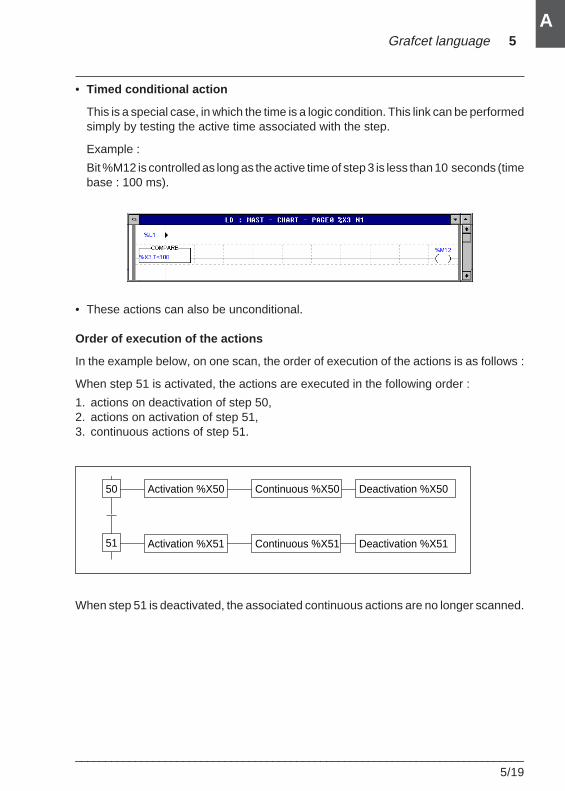
Grafcet language 5
___________________________________________________________________________5/19
A
• Timed conditional action
This is a special case, in which the time is a logic condition. This link can be performedsimply by testing the active time associated with the step.
Example :
Bit %M12 is controlled as long as the active time of step 3 is less than 10 seconds (timebase : 100 ms).
• These actions can also be unconditional.
Order of execution of the actions
In the example below, on one scan, the order of execution of the actions is as follows :
When step 51 is activated, the actions are executed in the following order :
1. actions on deactivation of step 50,2. actions on activation of step 51,3. continuous actions of step 51.
When step 51 is deactivated, the associated continuous actions are no longer scanned.
50 Activation %X50
51
Continuous %X50 Deactivation %X50
Activation %X51 Continuous %X51 Deactivation %X51
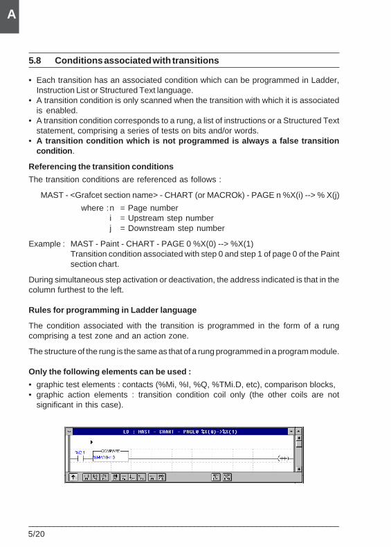
5/20___________________________________________________________________________
A
5.8 Conditions associated with transitions
• Each transition has an associated condition which can be programmed in Ladder,Instruction List or Structured Text language.
• A transition condition is only scanned when the transition with which it is associatedis enabled.
• A transition condition corresponds to a rung, a list of instructions or a Structured Textstatement, comprising a series of tests on bits and/or words.
• A transition condition which is not programmed is always a false transitioncondition .
Referencing the transition conditions
The transition conditions are referenced as follows :
MAST - <Grafcet section name> - CHART (or MACROk) - PAGE n %X(i) --> % X(j)
where :n = Page numberi = Upstream step numberj = Downstream step number
Example : MAST - Paint - CHART - PAGE 0 %X(0) --> %X(1)Transition condition associated with step 0 and step 1 of page 0 of the Paintsection chart.
During simultaneous step activation or deactivation, the address indicated is that in thecolumn furthest to the left.
Rules for programming in Ladder language
The condition associated with the transition is programmed in the form of a rungcomprising a test zone and an action zone.
The structure of the rung is the same as that of a rung programmed in a program module.
Only the following elements can be used :
• graphic test elements : contacts (%Mi, %I, %Q, %TMi.D, etc), comparison blocks,• graphic action elements : transition condition coil only (the other coils are not
significant in this case).
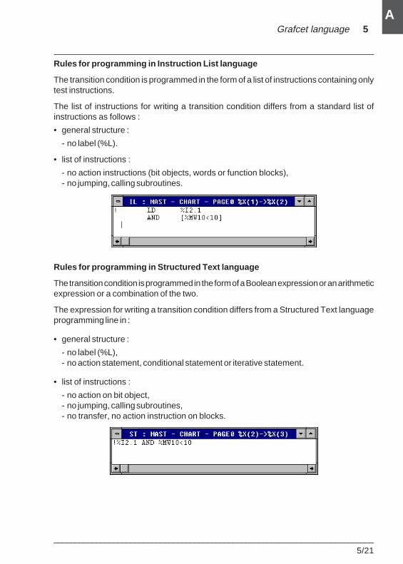
Grafcet language 5
___________________________________________________________________________5/21
A
Rules for programming in Instruction List language
The transition condition is programmed in the form of a list of instructions containing onlytest instructions.
The list of instructions for writing a transition condition differs from a standard list ofinstructions as follows :
• general structure :
- no label (%L).
• list of instructions :
- no action instructions (bit objects, words or function blocks),- no jumping, calling subroutines.
Rules for programming in Structured Text language
The transition condition is programmed in the form of a Boolean expression or an arithmeticexpression or a combination of the two.
The expression for writing a transition condition differs from a Structured Text languageprogramming line in :
• general structure :
- no label (%L),- no action statement, conditional statement or iterative statement.
• list of instructions :
- no action on bit object,- no jumping, calling subroutines,- no transfer, no action instruction on blocks.
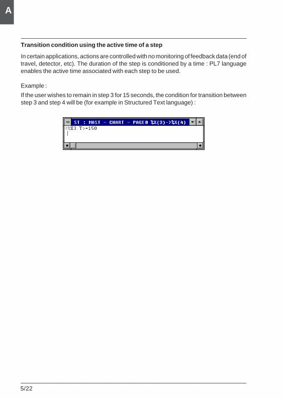
5/22___________________________________________________________________________
A
Transition condition using the active time of a step
In certain applications, actions are controlled with no monitoring of feedback data (end oftravel, detector, etc). The duration of the step is conditioned by a time : PL7 languageenables the active time associated with each step to be used.
Example :
If the user wishes to remain in step 3 for 15 seconds, the condition for transition betweenstep 3 and step 4 will be (for example in Structured Text language) :
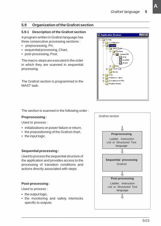
Grafcet language 5
___________________________________________________________________________5/23
A
5.9 Organization of the Grafcet section
5.9-1 Description of the Grafcet section
A program written in Grafcet language hasthree consecutive processing sections :• preprocessing, Prl,• sequential processing, Chart,• post-processing, Post.
The macro-steps are executed in the orderin which they are scanned in sequentialprocessing.
The Grafcet section is programmed in theMAST task.
The section is scanned in the following order :
Preprocessing :
Used to process :
• initializations on power failure or return,• the prepositioning of the Grafcet chart,• the input logic.
Sequential processing :
Used to process the sequential structure ofthe application and provides access to theprocessing of transition conditions andactions directly associated with steps.
Post-processing :
Used to process :
• the output logic,• the monitoring and safety interlocks
specific to outputs.
Sequential processingGrafcet
Post-processing
Ladder, InstructionList or Structured Text
language
Preprocessing
Ladder, InstructionList or Structured Text
language
Grafcet section
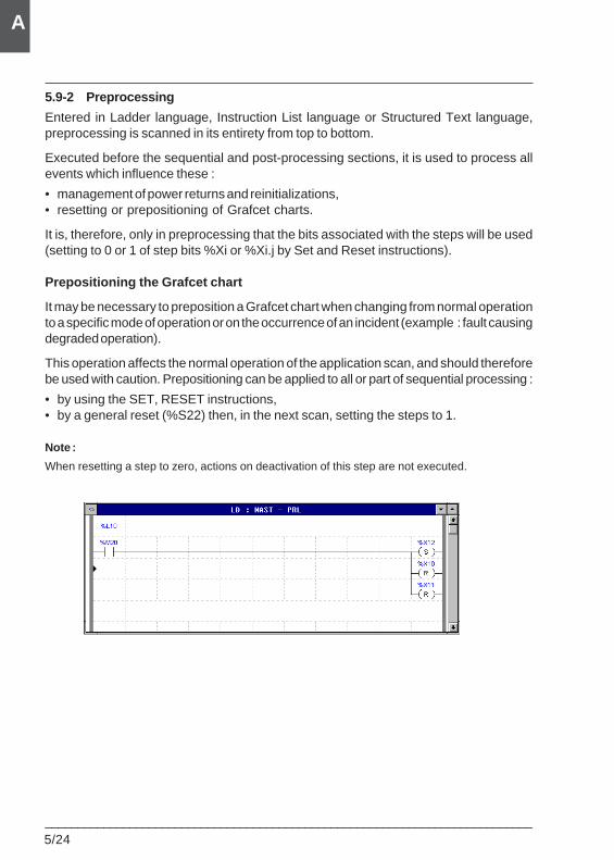
5/24___________________________________________________________________________
A
5.9-2 Preprocessing
Entered in Ladder language, Instruction List language or Structured Text language,preprocessing is scanned in its entirety from top to bottom.
Executed before the sequential and post-processing sections, it is used to process allevents which influence these :
• management of power returns and reinitializations,• resetting or prepositioning of Grafcet charts.
It is, therefore, only in preprocessing that the bits associated with the steps will be used(setting to 0 or 1 of step bits %Xi or %Xi.j by Set and Reset instructions).
Prepositioning the Grafcet chart
It may be necessary to preposition a Grafcet chart when changing from normal operationto a specific mode of operation or on the occurrence of an incident (example : fault causingdegraded operation).
This operation affects the normal operation of the application scan, and should thereforebe used with caution. Prepositioning can be applied to all or part of sequential processing :
• by using the SET, RESET instructions,• by a general reset (%S22) then, in the next scan, setting the steps to 1.
Note :
When resetting a step to zero, actions on deactivation of this step are not executed.
Grafcet language 5
___________________________________________________________________________5/25
A
5.9-3 The use of system bits in preprocessing
As the system bits associated with the Grafcet chart are numbered in order of priority(%S21 to %S24), when several of them are simultaneously set to 1 in preprocessing, theyare processed one by one in ascending order (only one is effective per scan cycle). Thesebits are effective at the start of sequential processing.
Initializing the Grafcet chart : %S21
Normally at 0, setting %S21 to 1 causes :
• the deactivation of the active steps,• the activation of the initial steps.
Set to 1 Reset to 0
• By setting %S0 to 1 • By the system at the start of• By the user program sequential processing• By the terminal (1) • By the user program
• By the terminal
• UseWhen managed by the user program, %S21 must be set to 0 or 1 in preprocessing .
Resetting the Grafcet chart to zero : %S22
Normally at 0, setting %S22 to 1 causes the deactivation of the active steps of all sequentialprocessing.
Set to 1 Reset to 0
• By the user program • By the system at the end of• By the terminal (1) post-processing
• Use- this bit must be set to 1 in preprocessing ,- resetting %S22 to 0 is managed by the system; it need not, therefore, be reset to 0 by
the program or the terminal.
To restart sequential processing in a given situation, the application must contain aprocedure for initializing or prepositioning the Grafcet chart.
(1) In the Grafcet debug screen or in the animation table
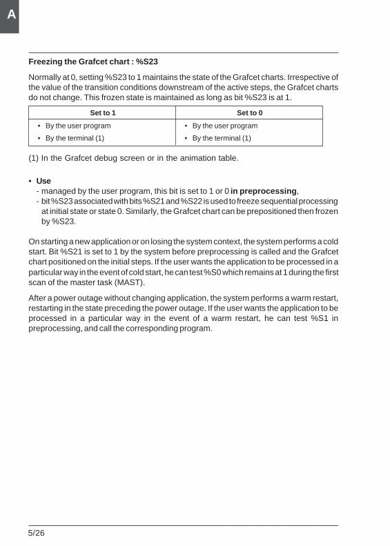
5/26___________________________________________________________________________
A
Freezing the Grafcet chart : %S23
Normally at 0, setting %S23 to 1 maintains the state of the Grafcet charts. Irrespective ofthe value of the transition conditions downstream of the active steps, the Grafcet chartsdo not change. This frozen state is maintained as long as bit %S23 is at 1.
Set to 1 Set to 0
• By the user program • By the user program
• By the terminal (1) • By the terminal (1)
(1) In the Grafcet debug screen or in the animation table.
• Use- managed by the user program, this bit is set to 1 or 0 in preprocessing ,- bit %S23 associated with bits %S21 and %S22 is used to freeze sequential processing
at initial state or state 0. Similarly, the Grafcet chart can be prepositioned then frozenby %S23.
On starting a new application or on losing the system context, the system performs a coldstart. Bit %S21 is set to 1 by the system before preprocessing is called and the Grafcetchart positioned on the initial steps. If the user wants the application to be processed in aparticular way in the event of cold start, he can test %S0 which remains at 1 during the firstscan of the master task (MAST).
After a power outage without changing application, the system performs a warm restart,restarting in the state preceding the power outage. If the user wants the application to beprocessed in a particular way in the event of a warm restart, he can test %S1 inpreprocessing, and call the corresponding program.
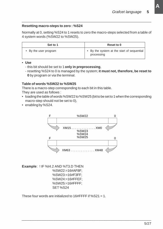
Grafcet language 5
___________________________________________________________________________5/27
A
Resetting macro-steps to zero : %S24
Normally at 0, setting %S24 to 1 resets to zero the macro-steps selected from a table of4 system words (%SW22 to %SW25).
Set to 1 Reset to 0
• By the user program • By the system at the start of sequentialprocessing
• Use- this bit should be set to 1 only in preprocessing ,- resetting %S24 to 0 is managed by the system; it must not, therefore, be reset to
0 by program or via the terminal.
Table of words %SW22 to %SW25There is a macro-step corresponding to each bit in this table.They are used as follows :• loading the table of words %SW22 to %SW25 (bit to be set to 1 when the corresponding
macro-step should not be set to 0),• enabling by %S24.
Example : ! IF %I4.2 AND %T3.D THEN%SW22:=16#AF8F;%SW23:=16#F3FF;%SW24:=16#FFEF;%SW25:=16#FFFF;SET %S24
These four words are initialized to 16#FFFF if %S21 = 1.
F 0%SW22
XM15 . . . . . . . . . . . . . . XM0%SW23%SW24%SW25F 0
XM63 . . . . . . . . . . . . . . XM48
5/28___________________________________________________________________________
A
5.9-4 Sequential processing
This processing section is used to program the sequential structure of the application.Sequential processing consists of :
• the main chart organized into 8 pages.
In the main chart, several unconnected Grafcet charts can be programmed and runsimultaneously.
Principle of evolution
The evolution of the Grafcet chart is managed as follows :
Phase 1 :
1. Evaluation of the condition of enabled transitions.
2. Request to deactivate associated upstream steps.
3. Request to activate relevant downstream steps.
Phase 2 :
Evolution of the state of the Grafcet chart as a function of the cleared transitions :
1. Deactivation of the steps upstream of the cleared transitions.
2. Activation of the steps downstream of the cleared transitions.
3. Disabling the cleared transitions.
4. Enabling the transitions downstream of the new activated steps.
The system updates two tables dedicated respectively to step activity and enabledtransitions :
• the step activity table stores, for the current scan, the active steps, the steps to beactivated and the steps to be deactivated,
• the enabled transitions table stores, for the current scan, the transitions locateddownstream of the steps concerned with the preceding table.
Phase 3 :
The actions associated with the active steps are executed in the following order :
1. Actions on deactivation of the steps to be deactivated.
2. Actions on activation of the steps to be activated.
3. Continuous actions of the active steps.
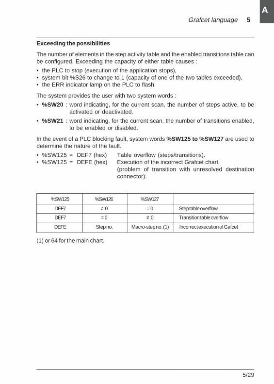
Grafcet language 5
___________________________________________________________________________5/29
A
Exceeding the possibilities
The number of elements in the step activity table and the enabled transitions table canbe configured. Exceeding the capacity of either table causes :
• the PLC to stop (execution of the application stops),• system bit %S26 to change to 1 (capacity of one of the two tables exceeded),• the ERR indicator lamp on the PLC to flash.
The system provides the user with two system words :
• %SW20 : word indicating, for the current scan, the number of steps active, to beactivated or deactivated.
• %SW21 : word indicating, for the current scan, the number of transitions enabled,to be enabled or disabled.
In the event of a PLC blocking fault, system words %SW125 to %SW127 are used todetermine the nature of the fault.
• %SW125 = DEF7 (hex) Table overflow (steps/transitions).• %SW125 = DEFE (hex) Execution of the incorrect Grafcet chart.
(problem of transition with unresolved destinationconnector).
%SW125 %SW126 %SW127
DEF7 ≠ 0 = 0 Step table overflow
DEF7 = 0 ≠ 0 Transition table overflow
DEFE Step no. Macro-step no. (1) Incorrect execution of Gafcet
(1) or 64 for the main chart.
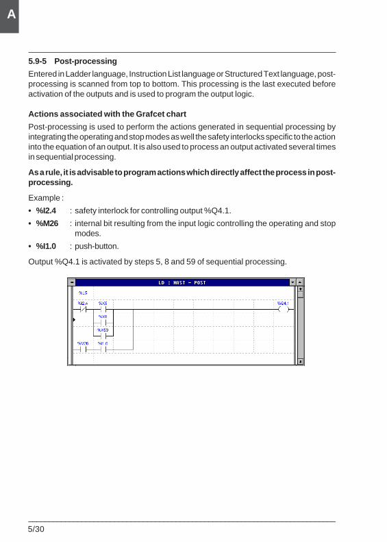
5/30___________________________________________________________________________
A
5.9-5 Post-processing
Entered in Ladder language, Instruction List language or Structured Text language, post-processing is scanned from top to bottom. This processing is the last executed beforeactivation of the outputs and is used to program the output logic.
Actions associated with the Grafcet chart
Post-processing is used to perform the actions generated in sequential processing byintegrating the operating and stop modes as well the safety interlocks specific to the actioninto the equation of an output. It is also used to process an output activated several timesin sequential processing.
As a rule, it is advisable to program actions which directly affect the process in post-processing.
Example :
• %I2.4 : safety interlock for controlling output %Q4.1.
• %M26 : internal bit resulting from the input logic controlling the operating and stopmodes.
• %I1.0 : push-button.
Output %Q4.1 is activated by steps 5, 8 and 59 of sequential processing.
Grafcet language 5
___________________________________________________________________________5/31
A
Actions independent of the Grafcet chart
Post-processing is also used to program the outputs which are independent ofsequential processing.
Monitoring the execution of the Grafcet chart
In certain circumstances, it may be necessary to monitor the operation of the Grafcetchart by testing the active time of certain steps.
This time is tested by comparing with either a minimum value or a maximum valuedefined by the user. The use made of the fault indication is at the user's discretion(indication, special operating procedure, transmission of a message).
Example : ! IF (%X2.T > 100 AND %X2) THENSET %Q4.0 ;
END_IF ;

5/32___________________________________________________________________________
A
DFBs 6
___________________________________________________________________________6/1
A
A
6.1 Presentation of DFBs
6.1-1 General
With PL7 Pro software, the user can create function blocks adapted to his applicationrequirements.
These user function blocks can be used to structure an application. They are usedwhenever a program sequence is repeated several times in the application or to freezestandard programming (for example : algorithm to control a motor which takes intoaccount local safety measures).
They can be shared by all programmers and used in the same application or in otherapplications (export/import function).
The use of a DFB in an application offers :• simplified design and entry of the program
• increased legibility of the program
• easier program debugging (all variables manipulated by the DFB can be identifiedon its interface).
• reduced volume of code generated (the code corresponding to the DFB is onlyloaded once, however many times the DFB is called in the program)
In relation to the subroutine, they allow :• easier entry of processing parameters
• the use of internal DFB variables which are independent of the application
• the independent testing of the application
In Ladder language, the block can be displayed graphically to make programming anddebugging easier.
In addition, DFBs make use of remanent data.
A DFB is created using PL7 Pro software. A DFB can be used with PL7 Pro or PL7Junior software on a TSX/PCX/PMX57 PLC.
DFBs (Derived Function Blocks) can be programmed in Structured Text and Ladderlanguages by the designer and can be used in Ladder, Structured Text andInstruction List languages.
Section 66 DFBs
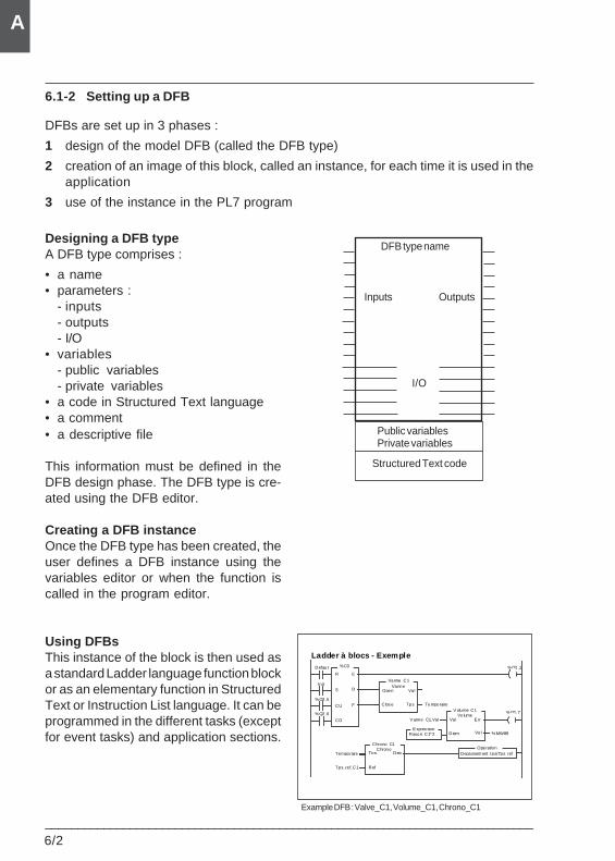
6/2___________________________________________________________________________
A
6.1-2 Setting up a DFB
DFBs are set up in 3 phases :
1 design of the model DFB (called the DFB type)
2 creation of an image of this block, called an instance, for each time it is used in theapplication
3 use of the instance in the PL7 program
Designing a DFB typeA DFB type comprises :
• a name• parameters :
- inputs- outputs- I/O
• variables- public variables- private variables
• a code in Structured Text language• a comment• a descriptive file
This information must be defined in theDFB design phase. The DFB type is cre-ated using the DFB editor.
Creating a DFB instanceOnce the DFB type has been created, theuser defines a DFB instance using thevariables editor or when the function iscalled in the program editor.
Using DFBsThis instance of the block is then used asa standard Ladder language function blockor as an elementary function in StructuredText or Instruction List language. It can beprogrammed in the different tasks (exceptfor event tasks) and application sections.
DFB type name
Inputs Outputs
I/O
Public variablesPrivate variables
Structured Text code
Ladder à blocs - ExempleDefaut %C0
R E
%Q2.1
S
CU
CD
D
F
In it
%Q2.6
%Q2.5
Vanne_C1
Open
Clos e
ValVanne
V olume_C1
Val E rr
Diam Vol
Volume
E xpres sionRayon_C1*2
V anne_C1.Val
%MW89
%Q2.7
Tps Temporaire
Chrono_C1
Tps Dep
Ref
ChronoTemporaire
Tps_ref_C1
OperationDepassem ent_tps(Tps_ref_
Example DFB : Valve_C1, Volume_C1, Chrono_C1
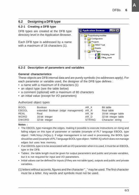
DFBs 6
___________________________________________________________________________6/3
A
A
6.2 Designing a DFB type
6.2-1 Creating a DFB type
DFB types are created at the DFB typedirectory level in the Application Browser.
Each DFB type is addressed by a namewith a maximum of 16 characters (1).
6.2-2 Description of parameters and variables
General characteristicsThese objects are DFB internal data and are purely symbolic (no addresses apply). Foreach parameter or variable used, the designer of the DFB type defines :• a name with a maximum of 8 characters (1)• an object type (see the table below)• a comment (optional) with a maximum of 80 characters• an initial value (except for I/O parameters)
Authorized object types
BOOL Boolean AR_X Bit tableEBOOL extended Boolean (edge management) AR_R Real tableREAL Real AR_W 16-bit integer tableWORD 16-bit integer AR_D 32-bit integer tableDWORD 32-bit integer STRING Character string
Notes :• The EBOOL type manages the edges, making it possible to execute instructions on rising and
falling edges on this type of parameter or variable (example of PL7 language EBOOL typeobject : %Mi,%Ixy.i,%Qxy.i). If edge management is not used in processing, the BOOL typeshould be used (example of PL7 language BOOL type object : %MWi:Xj) which does not manageedges but uses less memory.
• If an EBOOL type is to be associated with an I/O parameter when it is used, it must be an EBOOLtype in the DFB.
• Tables : the table length must be given for output parameters and public and private variables,but it is not required for input and I/O parameters.
• Initial values can be defined for inputs (if they are not table type), outputs and public and privatevariables.
(1) letters without accents, figures and the character "_" may be used. The first charactermust be a letter. Key words and symbols must not be used.
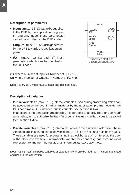
6/4___________________________________________________________________________
A
Description of parameters
• Inputs : (max. : 15 (1)) data to be suppliedto the DFB by the application program.In read-only mode, these parameterscannot be modified in the DFB code.
• Outputs : (max. : 15 (2)) data generatedby the DFB towards the application pro-gram.
• I/O : (max. : 15 (1) and (2)) inputparameters which can be modified inthe DFB code.
(1) where Number of Inputs + Number of I/O < 15(2) where Number of Outputs + Number of I/O < 15
Note : every DFB must have at least one Boolean input.
Description of variables
• Public variables : (max. : 100) internal variables used during processing which canbe accessed by the user in adjust mode or by the application program outside theDFB code (as a DFB instance public variable, see section 6.4-4).In addition to the general characteristics, it is possible to specify read-only or read/write rights, and to authorize the transfer of current values to initial values to be saved(see section 6.4-5).
• Private variables : (max. : 100) internal variables in the function block code. Thesevariables are calculated and used within the DFB but are not used outside the DFB.These variables are used for programming the block but are of no interest to the userof the block (for example : intermediate variable for connecting one combinationalexpression to another, the result of an intermediate calculation, etc)
Note : A DFB interface (public variables or parameters) can only be modified if it is not instantiatedand used in the application.
Control
Diff Accel
Speed
Enable
Actions
ErrorWORD
DWORD
BOOL
BOOL
WORD
WORD
Example of a block with :3 inputs, 2 outputs, 1 I/O
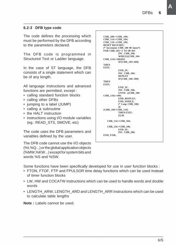
DFBs 6
___________________________________________________________________________6/5
A
A
6.2-3 DFB type code
The code defines the processing whichmust be performed by the DFB accordingto the parameters declared.
The DFB code is programmed inStructured Text or Ladder language.
In the case of ST language, the DFBconsists of a single statement which canbe of any length.
All language instructions and advancedfunctions are permitted, except :• calling standard function blocks• calling other DFBs• jumping to a label (JUMP)• calling a subroutine• the HALT instruction• instructions using I/O module variables
(eg.: READ_STS, SMOVE, etc)
The code uses the DFB parameters andvariables defined by the user.
The DFB code cannot use the I/O objects(%I,%Q...) or the global application objects(%MW,%KW...) except for system bits andwords %S and %SW.
Some functions have been specifically developed for use in user function blocks :• FTON, FTOF, FTP and FPULSOR time delay functions which can be used instead
of timer function blocks
• LW, HW and COCATW instructions which can be used to handle words and doublewords
• LENGTH_ARW, LENGTH_ARD and LENGTH_ARR instructions which can be usedto calculate table lengths
Note : Labels cannot be used.
CHR_200:=CHR_100;CHR_114:=CHR_104;CHR_116:=CHR_106;RESET RESTART;(* Increment CHR_100 80 times*)FOR CHR_102:=1 TO 80 DO
INC CHR_100;WHILE((CHR_104-
CHR_114)<100)DOIF(CHR_104>400)
THENEXIT;
END_IF;INC CHR_104;REPEATIF(CHR_106>300)
THENEXIT;
END_IF;INC CHR_106;UNTIL ((CHR_100-
CHR_116)>100)END_REPEAT;END_WHILE;(* Loop CHR_106)IF
(CHR_106=CHR_116)THEN EXIT;ELSE
CHR_114:=CHR_104;
CHR_116:=CHR_106;END_IF;INC CHR_200;
END_FOR;
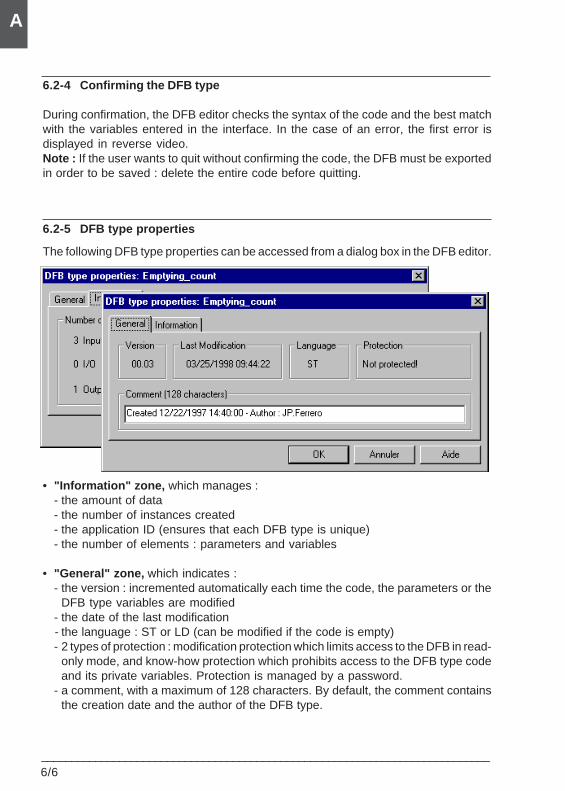
6/6___________________________________________________________________________
A
6.2-4 Confirming the DFB type
During confirmation, the DFB editor checks the syntax of the code and the best matchwith the variables entered in the interface. In the case of an error, the first error isdisplayed in reverse video.Note : If the user wants to quit without confirming the code, the DFB must be exportedin order to be saved : delete the entire code before quitting.
6.2-5 DFB type properties
The following DFB type properties can be accessed from a dialog box in the DFB editor.
• "Information" zone, which manages :- the amount of data- the number of instances created- the application ID (ensures that each DFB type is unique)- the number of elements : parameters and variables
• "General" zone, which indicates :- the version : incremented automatically each time the code, the parameters or the
DFB type variables are modified- the date of the last modification- the language : ST or LD (can be modified if the code is empty)- 2 types of protection : modification protection which limits access to the DFB in read-
only mode, and know-how protection which prohibits access to the DFB type codeand its private variables. Protection is managed by a password.
- a comment, with a maximum of 128 characters. By default, the comment containsthe creation date and the author of the DFB type.
DFBs 6
___________________________________________________________________________6/7
A
A
6.2-6 Descriptive file
The descriptive file is a free entry field with a maximum of 32,000 characters which isused to describe a DFB type.
6.2-7 DFB type properties
This is used to access the DFB type properties :• Display the number of DFBs in ST and LD present in the application• Inhibit the "Save/Restore" function for all the DFBs
This function is used to inhibit all the Save/Restore flags chosen for the public variablesof all the DFB types.This inhibit function has a "blanket" effect for all the DFBs since, when it is disabled, thechoices for each public variable of each DFB type are retained.
6.2-8 Importing/exporting a DFB type
The DFB types created in an application can be reused in any other application by theimport/export functions.
2 types of format are supported :• source : this format can be edited
• binary : this format cannot be edited. A DFB imported in this format can be read ormodified depending on the degree of protection applied.
Using these source or binary files, the user can create his own library.
Notes :Whenever a section is imported into an application, the DFB types used in that section must alsobe imported.
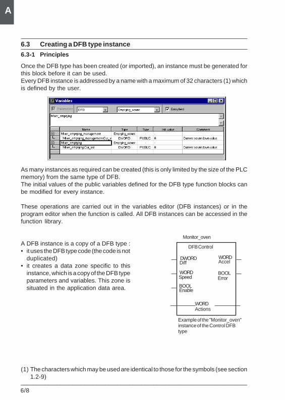
6/8___________________________________________________________________________
A
6.3 Creating a DFB type instance
6.3-1 Principles
Once the DFB type has been created (or imported), an instance must be generated forthis block before it can be used.Every DFB instance is addressed by a name with a maximum of 32 characters (1) whichis defined by the user.
As many instances as required can be created (this is only limited by the size of the PLCmemory) from the same type of DFB.The initial values of the public variables defined for the DFB type function blocks canbe modified for every instance.
These operations are carried out in the variables editor (DFB instances) or in theprogram editor when the function is called. All DFB instances can be accessed in thefunction library.
A DFB instance is a copy of a DFB type :• it uses the DFB type code (the code is not
duplicated)• it creates a data zone specific to this
instance, which is a copy of the DFB typeparameters and variables. This zone issituated in the application data area.
(1) The characters which may be used are identical to those for the symbols (see section1.2-9)
DFB Control
Diff Accel
Speed
Enable
Actions
ErrorWORD
DWORD
BOOL
BOOL
WORD
WORD
Example of the "Monitor_oven"instance of the Control DFBtype
Monitor_oven
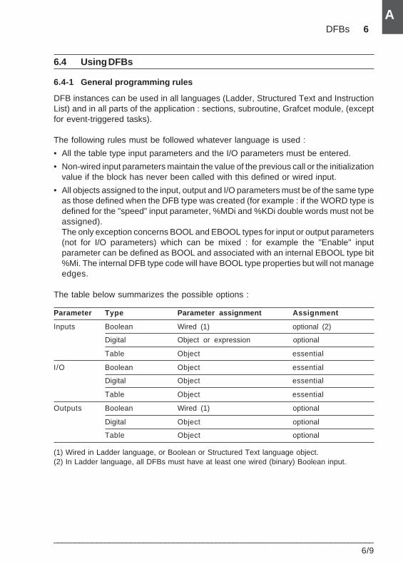
DFBs 6
___________________________________________________________________________6/9
A
A
6.4 Using DFBs
6.4-1 General programming rules
DFB instances can be used in all languages (Ladder, Structured Text and InstructionList) and in all parts of the application : sections, subroutine, Grafcet module, (exceptfor event-triggered tasks).
The following rules must be followed whatever language is used :
• All the table type input parameters and the I/O parameters must be entered.
• Non-wired input parameters maintain the value of the previous call or the initializationvalue if the block has never been called with this defined or wired input.
• All objects assigned to the input, output and I/O parameters must be of the same typeas those defined when the DFB type was created (for example : if the WORD type isdefined for the "speed" input parameter, %MDi and %KDi double words must not beassigned).The only exception concerns BOOL and EBOOL types for input or output parameters(not for I/O parameters) which can be mixed : for example the "Enable" inputparameter can be defined as BOOL and associated with an internal EBOOL type bit%Mi. The internal DFB type code will have BOOL type properties but will not manageedges.
The table below summarizes the possible options :
Parameter Type Parameter assignment Assignment
Inputs Boolean Wired (1) optional (2)
Digital Object or expression optional
Table Object essential
I/O Boolean Object essential
Digital Object essential
Table Object essential
Outputs Boolean Wired (1) optional
Digital Object optional
Table Object optional
(1) Wired in Ladder language, or Boolean or Structured Text language object.(2) In Ladder language, all DFBs must have at least one wired (binary) Boolean input.
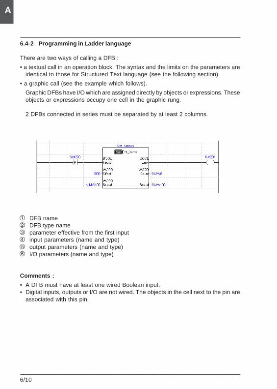
6/10___________________________________________________________________________
A
6.4-2 Programming in Ladder language
There are two ways of calling a DFB :
• a textual call in an operation block. The syntax and the limits on the parameters areidentical to those for Structured Text language (see the following section).
• a graphic call (see the example which follows).
Graphic DFBs have I/O which are assigned directly by objects or expressions. Theseobjects or expressions occupy one cell in the graphic rung.
2 DFBs connected in series must be separated by at least 2 columns.
1 DFB name2 DFB type name3 parameter effective from the first input4 input parameters (name and type)5 output parameters (name and type)6 I/O parameters (name and type)
Comments :
• A DFB must have at least one wired Boolean input.• Digital inputs, outputs or I/O are not wired. The objects in the cell next to the pin are
associated with this pin.
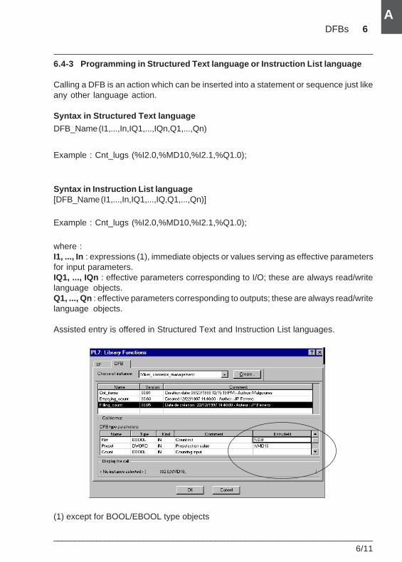
DFBs 6
___________________________________________________________________________6/11
A
A
6.4-3 Programming in Structured Text language or Instruction List language
Calling a DFB is an action which can be inserted into a statement or sequence just likeany other language action.
Syntax in Structured Text language
DFB_Name (I1,...,In,IQ1,...,IQn,Q1,...,Qn)
Example : Cnt_lugs (%I2.0,%MD10,%I2.1,%Q1.0);
Syntax in Instruction List language[DFB_Name (I1,...,In,IQ1,...,IQ,Q1,...,Qn)]
Example : Cnt_lugs (%I2.0,%MD10,%I2.1,%Q1.0);
where :I1, ..., In : expressions (1), immediate objects or values serving as effective parametersfor input parameters.IQ1, ..., IQn : effective parameters corresponding to I/O; these are always read/writelanguage objects.Q1, ..., Qn : effective parameters corresponding to outputs; these are always read/writelanguage objects.
Assisted entry is offered in Structured Text and Instruction List languages.
(1) except for BOOL/EBOOL type objects
6/12___________________________________________________________________________
A
6.4-4 Accessing variables
Only the output parameters and public variables can be accessed as objects in theapplication program outside the body of the function block. Their syntax is as follows :
DFB_name.parameter_name
where DFB_name is the name given to the DFB instance used (32 charactersmaximum) and parameter_name is the name given to the output parameter or thepublic variable (8 characters maximum).
Example : Control.Diff for the Diff output of the DFB instance called Control.
6.4-5 Saving and restoring public variables
Public variables, modified by program or by adjustment, can be saved instead of theinitialization values (defined in the DFB instances) by setting system bit %S94 to 1. Thisreplacement is only possible if it has been authorized at the level of each DFB typevariable.The values saved in this way are reapplied when system bit %S95 is set to 1 or whenthe PLC is re-initialized.
Inhibition of the "Save/Restore" function for all the DFBsrefer to section 6.2-7.
6.4-6 Executing DFBs
A DFB instance is executed in the following order :• The input and I/O parameters are loaded using the effective parameters. Each
undefined input takes the initial value defined in the DFB type on initialization or ona cold start, then the current value of the parameter.The input parameters (except for table type) are treated according to value.The I/O parameters are treated according to address.
• The Structured Text code is executed.
• The output parameters are written.
PL7 software offers several tools for debugging the PL7 program and the DFBs :
• animation table : all the parameters and public variables are displayed and animatedin realtime. The required objects can be modified and forced.
• breakpoint, step-by-step and program diagnostics
• runtime screens : for debugging using a unified screen
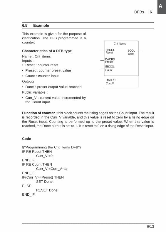
DFBs 6
___________________________________________________________________________6/13
A
A
6.5 Example
This example is given for the purpose ofclarification. The DFB programmed is acounter.
Characteristics of a DFB type
Name : Cnt_itemsInputs :• Reset : counter reset
• Preset : counter preset value
• Count : counter input
Outputs
• Done : preset output value reached
Public variable :
• Curr_V : current value incremented bythe Count input
Function of counter : this block counts the rising edges on the Count input. The resultis recorded in the Curr_V variable, and this value is reset to zero by a rising edge onthe Reset input. Counting is performed up to the preset value. When this value isreached, the Done output is set to 1. It is reset to 0 on a rising edge of the Reset input.
Code
!(*Programming the Cnt_items DFB*)IF RE Reset THEN
Curr_V:=0;END_IF;IF RE Count THEN
Curr_V:=Curr_V+1;END_IF;IF(Curr_V>=Preset) THEN
SET Done;ELSE
RESET Done;END_IF;
Cnt_items
Reset
Count
DoneEBOOL
EBOOL
BOOL
PresetDWORD
Curr_VDWORD
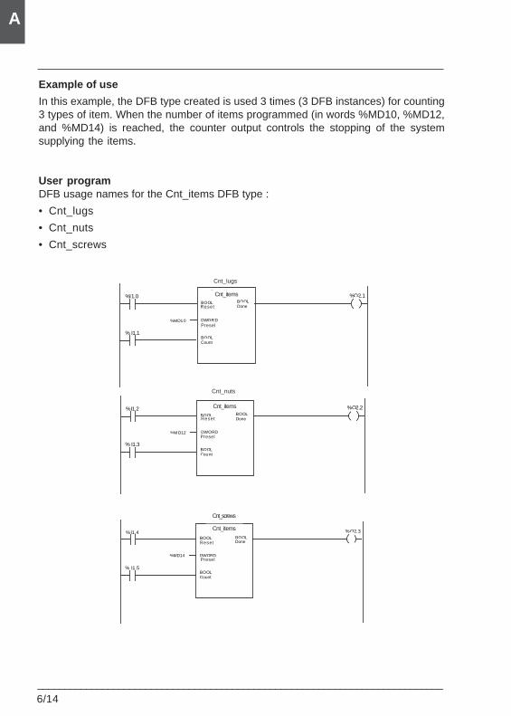
6/14___________________________________________________________________________
A
Example of use
In this example, the DFB type created is used 3 times (3 DFB instances) for counting3 types of item. When the number of items programmed (in words %MD10, %MD12,and %MD14) is reached, the counter output controls the stopping of the systemsupplying the items.
User programDFB usage names for the Cnt_items DFB type :
• Cnt_lugs
• Cnt_nuts
• Cnt_screws
Cpt_pièces
BOOLRaz
%Q2.1
DWORDPreset
% I1.1BOOLCount
Cpt_boulons
BOOLDone
%MD1 0
%I1.0
Cpt_pièces
BOOLRa z
%Q2.2
DWORDPreset
% I1.3BOOLCou nt
Cpt_écrous
BOOLDone
%M D12
%I1.2
Cpt_pi èces
BOOLRaz
%Q2.3
DWORDPreset
% I1.5BOOLCount
Cpt_v is
BOOLDone
%MD14
%I1.4
Presel
Presel
Presel
Cnt_lugs
Cnt_items
Cnt_items
Cnt_nuts
Cnt_items
Cnt_screws
Reset
Reset
Reset
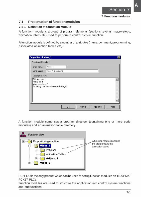
Function modules 7
___________________________________________________________________________7/1
A
A
7.1 Presentation of function modules
7.1-1 Definition of a function module
A function module is a group of program elements (sections, events, macro-steps,animation tables etc) used to perform a control system function.
A function module is defined by a number of attributes (name, comment, programming,associated animation tables etc).
Section 77 Function modules
A function module containsthe program and theanimation tables
A function module comprises a program directory (containing one or more codemodules) and an animation table directory.
PL7 PRO is the only product which can be used to set up function modules on TSX/PMX/PCX57 PLCs.Function modules are used to structure the application into control system functionsand subfunctions.
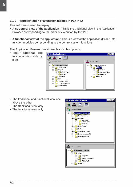
7/2___________________________________________________________________________
A
7.1-2 Representation of a function module in PL7 PRO
This software is used to display :• A structural view of the application : This is the traditional view in the Application
Browser corresponding to the order of execution by the PLC.
• A functional view of the application : This is a view of the application divided intofunction modules corresponding to the control system functions.
The Application Browser has 4 possible display options :• The traditional and
functional view side byside
• The traditional and functional view oneabove the other
• The traditional view only• The functional view only
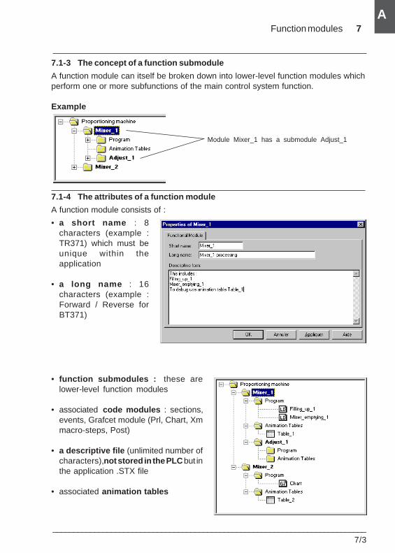
Function modules 7
___________________________________________________________________________7/3
A
A
7.1-3 The concept of a function submodule
A function module can itself be broken down into lower-level function modules whichperform one or more subfunctions of the main control system function.
Example
7.1-4 The attributes of a function module
A function module consists of :
• a short name : 8characters (example :TR371) which must beunique within theapplication
• a long name : 16characters (example :Forward / Reverse forBT371)
• function submodules : these arelower-level function modules
• associated code modules : sections,events, Grafcet module (Prl, Chart, Xmmacro-steps, Post)
• a descriptive file (unlimited number ofcharacters), not stored in the PLC but inthe application .STX file
• associated animation tables
Module Mixer_1 has a submodule Adjust_1
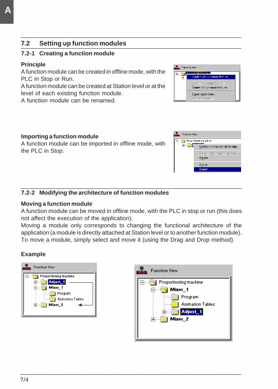
7/4___________________________________________________________________________
A
7.2 Setting up function modules
7.2-1 Creating a function module
PrincipleA function module can be created in offline mode, with thePLC in Stop or Run.A function module can be created at Station level or at thelevel of each existing function module.A function module can be renamed.
Importing a function moduleA function module can be imported in offline mode, withthe PLC in Stop.
7.2-2 Modifying the architecture of function modules
Moving a function moduleA function module can be moved in offline mode, with the PLC in stop or run (this doesnot affect the execution of the application).Moving a module only corresponds to changing the functional architecture of theapplication (a module is directly attached at Station level or to another function module).To move a module, simply select and move it (using the Drag and Drop method).
Example
Function modules 7
___________________________________________________________________________7/5
A
A
Detaching a function moduleDetaching a function module consists of breaking the links between a function moduleand the associated objects (code modules and animation tables).- The sections contained in the module are not deleted, but merely detached.- The animation tables associated with the modules are not deleted, but merelydetached from the module.
Deleting one or more function modules without deleting the code modules andanimation tablesTo delete a function module without deleting the code modules and animation tables,it is necessary to :1. Detach the module and submodules.2. Delete the module(s) in accordance with the procedure below.
Deleting a function module (with deletion of the code modules and animation tables)Deleting the module will delete the submodules.- The sections contained in the module are deleted.- The animation tables associated with the modules are deleted.
Deleting all the function modules (with deletion of the code modules and animationtables)Deleting the module will delete the submodules.
Deleting a section, a macro-step or an event in a function moduleRefer to section 7.3-2.
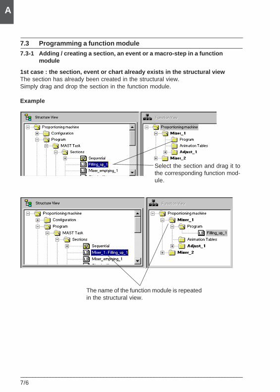
7/6___________________________________________________________________________
A
7.3 Programming a function module
7.3-1 Adding / creating a section, an event or a macro-step in a functionmodule
1st case : the section, event or chart already exists in the structural viewThe section has already been created in the structural view.Simply drag and drop the section in the function module.
Example
Select the section and drag it tothe corresponding function mod-ule.
The name of the function module is repeatedin the structural view.
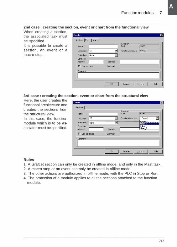
Function modules 7
___________________________________________________________________________7/7
A
A
2nd case : creating the section, event or chart from the functional viewWhen creating a section,the associated task mustbe specified.It is possible to create asection, an event or amacro-step.
3rd case : creating the section, event or chart from the structural viewHere, the user creates thefunctional architecture andcreates the sections fromthe structural view.In this case, the functionmodule which is to be as-sociated must be specified.
Rules1. A Grafcet section can only be created in offline mode, and only in the Mast task.2. A macro-step or an event can only be created in offline mode.3. The other actions are authorized in offline mode, with the PLC in Stop or Run.4. The protection of a module applies to all the sections attached to the function
module.
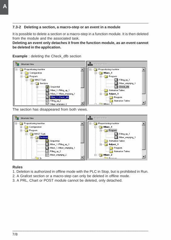
7/8___________________________________________________________________________
A
7.3-2 Deleting a section, a macro-step or an event in a module
It is possible to delete a section or a macro-step in a function module. It is then deletedfrom the module and the associated task.Deleting an event only detaches it from the function module, as an event cannotbe deleted in the application.
Example : deleting the Check_dfb section
The section has disappeared from both views.
Rules1. Deletion is authorized in offline mode with the PLC in Stop, but is prohibited in Run.2. A Grafcet section or a macro-step can only be deleted in offline mode.3. A PRL, Chart or POST module cannot be deleted, only detached.
Function modules 7
___________________________________________________________________________7/9
A
A
7.3-3 Adding / creating an animation table in a function module
1st case : the table already existsThe animation table has already been created in the structural view.Simply drag and drop the section in the function module at Animation table level.
2nd case : the table needs to be createdThe principle is identical to that for creation in the structural view.
Rules1. An animation table can be created in offline mode, with the PLC in Stop or Run.2. An animation table can be deleted in offline mode, with the PLC in Stop or Run.
7.3-4 Entering / modifying the descriptive file
The descriptive file is a free entry field which is used to describe the function module.It can be modified at all times and is stored in the application, but not in the PLC.
7/10___________________________________________________________________________
A
7.4 Executing the program
The organization of a function module and the distribution of the sections, events andGrafcet modules in the various modules does not affect the execution of the program.The program is executed in the order shown in the structural view.
7.5 Debugging the application
The user has functions enabling the incremental debugging of the application, functionmodule by function module.
Deactivating all the sections attached to a function moduleThis action consists of forcing all the activation conditions of the module sections to 0.
Activating all the sections attached to a function moduleThis action consists of forcing all the activation conditions of the module sections to 1.
Canceling forcing of all the sections attached to a function moduleThis action consists of unforcing all the activation conditions of the module sections.
7.6 Application documentation file
PL7 Pro is used to create the functional documentation file for the application,comprising :• the title page• the contents• the configuration• the tree structure of the function modules (with reference to the attached sections,
events and Grafcet modules only)• the program• the cross references, with references to the function modules which use the variables• the variables• the footer
Function modules 7
___________________________________________________________________________7/11
A
A
7.7 Importing and exporting the source file for a function module
7.7-1 Exporting
Exporting a function module involves :• exporting the sections, events and Grafcet modules which make up the module• exporting the function submodules which make up the function moduleThe short name and role name are exported and are therefore restored at the time ofimport.The function to export a function module can be accessed in offline mode and/or inonline mode, with the PLC in Stop.
CommentAnimation tables are not processed in the PL7 source file : for this reason, they areneither exported nor imported, even if they are attached to a function module.
7.7-2 Importing
Importing a function module is similar to creation, involving :• importing the sections, events and Grafcet modules which make up the module• importing the function submodules which make up the function moduleThe short name and role name are exported and are therefore restored at the time ofimport.If a section, an event, a Grafcet module or a function submodule comprising theimported function module already exists with the same name, the software allows theuser to enter a new name.The import of a function module makes it possible to correct a code error or errors inthe sections, events and Grafcet modules associated with the module.The function can be accessed in offline mode and/or in online mode, with the PLC inStop.
2 import procedures are available :• import without reassignment• import with reassignment
Importing with reassignment is used to modify various elements :- the names of the modules, Section, Task, Grafcet chart and macro-steps, Evti- the names of the Symbols (and associated comments) and Addresses- the I/O module addresses- DFB : comment field and the target name of all instances- the target SR and macro-steps

7/12___________________________________________________________________________
A
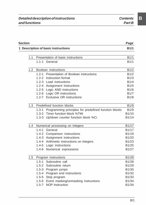
___________________________________________________________________________B/1
Detailed description of instructions Contentsand functions Part B
Section Page
___________________________________________________________________________
B
1 Description of basic instructions B1/1
1.1 Presentation of basic instructions B1/11.1-1 General B1/1
1.2 Boolean instructions B1/21.2-1 Presentation of Boolean instructions B1/21.2-2 Instruction format B1/31.2-3 Load instructions B1/41.2-4 Assignment instructions B1/51.2-5 Logic AND instructions B1/61.2-6 Logic OR instructions B1/71.2-7 Exclusive OR instructions B1/8
1.3 Predefined function blocks B1/91.3-1 Programming principles for predefined function blocks B1/91.3-2 Timer function block %TMi B1/101.3-3 Up/down counter function block %Ci B1/14
1.4 Numerical processing on integers B1/171.4-1 General B1/171.4-2 Comparison instructions B1/191.4-3 Assignment instructions B1/201.4-4 Arithmetic instructions on integers B1/231.4-5 Logic instructions B1/251.4-6 Numerical expressions B1/27
1.5 Program instructions B1/281.5-1 Subroutine call B1/281.5-2 Subroutine return B1/291.5-3 Program jumps B1/301.5-4 Program end instructions B1/321.5-5 Stop program B1/331.5-6 Event masking/unmasking instructions B1/341.5-7 NOP Instruction B1/34
___________________________________________________________________________
B/2
Detailed description of instructions Contentsand functions Part B
Section Page
___________________________________________________________________________
B
2 Description of advanced instructions B2/1
2.1 Presentation of advanced instructions B2/12.1-1 General B2/1
2.2 Advanced predefined function blocks B2/22.2-1 Monostable function block %MNi B2/22.2-2 Register function block %Ri B2/52.2-3 Drum controller function block %DRi B2/92.2-4 Timer function block %Ti (Series 7) B2/13
2.3 Vertical comparison blocks B2/17
2.4 Shift instructions B2/19
2.5 Floating point instructions B2/202.5-1 General B2/202.5-2 Floating point comparison instructions B2/222.5-3 Floating point assignment instructions B2/232.5-4 Floating point arithmetic instructions B2/242.5-5 Logarithmic and exponential instructions B2/252.5-6 Trigonometric instructions B2/262.5-7 Conversion instructions B2/28
2.6 Numeric conversion instructions B2/292.6-1 BCD <--> Binary conversion instructions B2/292.6-2 Integer <--> Floating point conversion instructions B2/312.6-3 Gray --> Integer conversion instructions B2/332.6-4 Word <--> double word conversion instructions B2/34
___________________________________________________________________________B/3
Detailed description of instructions Contentsand functions Part B
Section Page
___________________________________________________________________________
B
2.7 Word table instructions B2/352.7-1 General B2/352.7-2 Word table assignment B2/362.7-3 Arithmetic instructions on tables B2/382.7-4 Logic instructions on tables B2/392.7-5 Summing function on tables B2/402.7-6 Table comparison functions B2/412.7-7 Find functions on tables B2/432.7-8 Find maximum and minimum values function on tables B2/452.7-9 Number of occurrences of a value in a table B2/462.7-10 Circular shift function on tables B2/472.7-11 Sort function on tables B2/492.7-12 Table length calculation function B2/50
2.8 Character string instructions B2/512.8-1 Format of a string or table of characters B2/512.8-2 Character string assignment B2/522.8-3 Alphanumeric comparisons B2/532.8-4 Numeric <---> ASCII conversion functions B2/542.8-5 Binary --->ASCII conversion B2/542.8-6 ASCII ---> Binary conversion B2/562.8-7 Floating point ---> ASCII conversion B2/572.8-8 ASCII --> Floating point conversion B2/582.8-9 Concatenation of two strings B2/592.8-10 Deletion of a character substring B2/602.8-11 Insertion of a character substring B2/612.8-12 Replacement of a character substring B2/632.8-13 Extraction of a character substring B2/652.8-14 Extraction of characters B2/672.8-15 Comparison of two character strings B2/692.8-16 Search for a character substring B2/702.8-17 Length of a character string B2/71
___________________________________________________________________________
B/4
Detailed description of instructions Contentsand functions Part B
Section Page
___________________________________________________________________________
B
2.9 Time management instructions : Date, Time of day, Duration B2/722.9-1 Parameter format B2/722.9-2 Use of system bits and words - General B2/742.9-3 Realtime clock function B2/752.9-4 Read system date B2/772.9-5 Update system date B2/772.9-6 Read date and stop code B2/782.9-7 Read day of the week B2/792.9-8 Add / Remove a duration at a date B2/802.9-9 Add / Remove a duration at a time of day B2/812.9-10 Difference between two dates (no time) B2/832.9-11 Difference between two dates (with time) B2/842.9-12 Difference between two times B2/852.9-13 Convert a Date to a character string B2/862.9-14 Convert a complete Date to a character string B2/872.9-15 Convert a Duration to a character string B2/882.9-16 Convert a Time of day to a character string B2/892.9-17 Convert a Duration to HHHH:MM:SS B2/91
2.10 Bit table instructions B2/922.10-1 Copy one bit table to another bit table B2/922.10-2 Bit table logic instructions B2/932.10-3 Copy from a bit table to a word table B2/942.10-4 Copy from a word table to a bit table B2/96
2.11 "Orphee" functions : shift, counter B2/982.11-1 Shifts on words with retrieval of shifted bits B2/982.11-2 Up/down counting with indication of over/underflow B2/1012.11-3 Circular shift operations B2/103
2.12 Time delay functions B2/1052.12-1 General B2/1052.12-2 FTON on-delay function B2/1052.12-3 FTOF off-delay function B2/1072.12-4 FTP pulse delay function B2/1082.12-5 FPULSOR function for generating square wave signals B2/109
___________________________________________________________________________B/5
Detailed description of instructions Contentsand functions Part B
Section Page
___________________________________________________________________________
B
2.13 Data archiving functions B2/1112.13-1 General B2/1112.13-2 Initializing the archiving zone B2/1122.13-3 Writing data to the archiving zone B2/1142.13-4 Reading data from the archiving zone B2/116
3 System bits and words B3/1
3.1 System bits B3/13.1-1 List of system bits B3/13.1-2 Detailed description of system bits B3/3
3.2 System words B3/93.2-1 List of system words B3/93.2-2 Detailed description of system words B3/11
4 Differences between PL7-2/3 and PL7 Micro/Junior B4/1
4.1 Differences between PL7-2/3 and PL7-Micro/Junior B4/1
5 List of reserved words B5/1
5.1 Reserved words B5/1
6 Conformity to the IEC 1131-1 standard B6/1
6.1 Conformity to the IEC 1131-3 standard B6/16.1.1 Conformity tables B6/1
7 Quick reference guide B7/1
7.1 Quick reference guide B7/1
___________________________________________________________________________
B/6
Detailed description of instructions Contentsand functions Part B
Section Page
___________________________________________________________________________
B
8 Performance B8/1
8.1 General B8/1
8.2 TSX 37 performance B8/38.2.1 Boolean instructions B8/38.2.2 Function blocks B8/48.2.3 Integer and floating point arithmetic B8/68.2.4 Program instructions B8/88.2.5 Command structure B8/88.2.6 Numeric conversions B8/98.2.7 Bit string B8/98.2.8 Word, double word and floating point value tables B8/118.2.9 Time management B8/148.2.10 Character strings B8/158.2.11 Application-specific functions and Orphee function B8/168.2.12 Explicit I/O B8/17
8.3 TSX 57 performance B8/188.3.1 Boolean instructions B8/198.3.2 Function blocks B8/208.3.3 Integer and floating point arithmetic B8/228.3.4 Program instructions B8/248.3.5 Command structure B8/248.3.6 Numeric conversions B8/258.3.7 Bit string B8/258.3.8 Word, double word and floating point value tables B8/278.3.9 Time management B8/308.3.10 Timer function B8/308.3.11 Character strings B8/318.3.12 Word extraction B8/318.3.13 Application-specific functions and Orphee function B8/328.3.14 Explicit I/O B8/338.3.15 DFB function block B8/35
___________________________________________________________________________B/7
Detailed description of instructions Contentsand functions Part B
Section Page
___________________________________________________________________________
B
8.4 Size of the application B8/388.4.1 Description of the memory zones B8/388.4.2 Memory size of PL7 objects B8/398.4.3 Module memory size B8/398.4.4 Memory size of advanced functions B8/45
8.5 Appendix : method of calculating the number of instructions B8/52
9 OLE Automation Server B9/1
9.1 Presentation B9/19.1-1 Warning B9/19.1-2 Introduction B9/29.1-3 Execution context B9/39.1-4 Operating modes B9/3
9.2 Implementation B9/49.2-1 Installation B9/49.2-2 Starting the server in offline mode (COM mode) B9/49.2-3 Starting the server in remote mode (DCOM) B9/59.2-4 Setting up the server for remote mode B9/6
9.3 PL7 server execution modes B9/7
9.4 Input points : OLE function B9/8
9.5 Description of OLE functions B9/109.5-1 OpenStx B9/109.5-2 CloseStx B9/109.5-3 ExportScyFile B9/119.5-4 ExportFefFile B9/129.5-5 DisconnectPLC B9/129.5-6 ConnectPLC B9/139.5-7 SaveStx B9/149.5-8 DownloadToPLC B9/149.5-9 UploadfromPLC B9/15
___________________________________________________________________________
B/8
Detailed description of instructions Contentsand functions Part B
Section Page
___________________________________________________________________________
B
9.5-10 GetSymbol B9/169.5-11 SetServerIHM B9/179.5-12 GetPL7State B9/189.5-13 GetSTXAppIdentity B9/189.5-14 GetPLCAppIdentity B9/199.5-15 SendCommandToPLC B9/209.5-16 SetDriverAndAdresse B9/219.5-17 OpenTool B9/219.5-18 SetPosPL7Windows B9/229.5-19 ShowProgram B9/239.5-20 CloseProgram B9/239.5-21 ShowIOModule B9/249.5-22 CloseIOModule B9/259.5-23 ShowDFB B9/269.5-24 CloseDFB B9/269.5-25 GetMessageError B9/279.5-26 GetServerVersion B9/27
9.6 Mechanism for accessing the PL7 OLE Automation Server B9/28
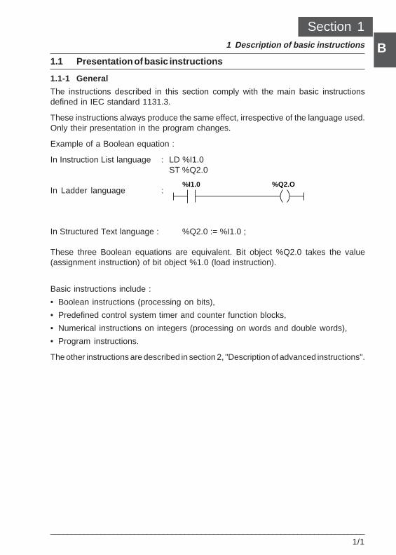
Description of basic instructions 1
___________________________________________________________________________1/1
B1.1 Presentation of basic instructions
1.1-1 General
The instructions described in this section comply with the main basic instructionsdefined in IEC standard 1131.3.
These instructions always produce the same effect, irrespective of the language used.Only their presentation in the program changes.
Example of a Boolean equation :
In Instruction List language : LD %I1.0ST %Q2.0
In Ladder language :
In Structured Text language : %Q2.0 := %I1.0 ;
These three Boolean equations are equivalent. Bit object %Q2.0 takes the value(assignment instruction) of bit object %1.0 (load instruction).
Basic instructions include :
• Boolean instructions (processing on bits),
• Predefined control system timer and counter function blocks,
• Numerical instructions on integers (processing on words and double words),
• Program instructions.
The other instructions are described in section 2, "Description of advanced instructions".
%I1.0 %Q2.O
Section 11 Description of basic instructions
Section 1
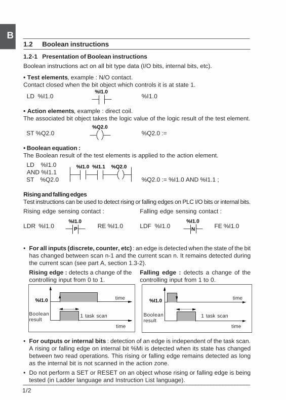
___________________________________________________________________________1/2
B
%I1.0
1.2 Boolean instructions
1.2-1 Presentation of Boolean instructions
Boolean instructions act on all bit type data (I/O bits, internal bits, etc).
• Test elements , example : N/O contact.Contact closed when the bit object which controls it is at state 1.
LD %I1.0 %I1.0
• Action elements , example : direct coil.The associated bit object takes the logic value of the logic result of the test element.
ST %Q2.0 %Q2.0 :=
• Boolean equation :The Boolean result of the test elements is applied to the action element.
LD %I1.0 AND %I1.1 ST %Q2.0 %Q2.0 := %I1.0 AND %I1.1 ;
Rising and falling edgesTest instructions can be used to detect rising or falling edges on PLC I/O bits or internal bits.
Rising edge sensing contact : Falling edge sensing contact :
LDR %I1.0 RE %I1.0 LDF %I1.0 FE %I1.0
• For all inputs (discrete, counter, etc) : an edge is detected when the state of the bithas changed between scan n-1 and the current scan n. It remains detected duringthe current scan (see part A, section 1.3-2).
Rising edge : detects a change of the Falling edge : detects a change of thecontrolling input from 0 to 1. controlling input from 1 to 0.
• For outputs or internal bits : detection of an edge is independent of the task scan.A rising or falling edge on internal bit %Mi is detected when its state has changedbetween two read operations. This rising or falling edge remains detected as longas the internal bit is not scanned in the action zone.
• Do not perform a SET or RESET on an object whose rising or falling edge is beingtested (in Ladder language and Instruction List language).
Booleanresult
time
time
1 task scanBooleanresult
1 task scan
time
time
%I1.0
%I1.0
N
%I1.0
P
%I1.0 %I1.1 %Q2.0
%Q2.0
%I1.0
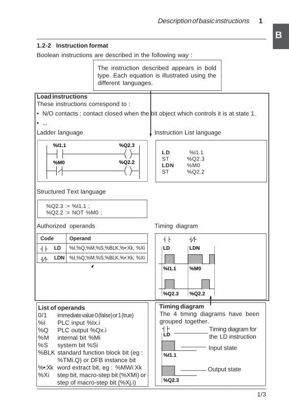
Description of basic instructions 1
___________________________________________________________________________1/3
B1.2-2 Instruction format
Boolean instructions are described in the following way :
Load instructionsThese instructions correspond to :
• N/O contacts : contact closed when the bit object which controls it is at state 1.
• ...
Ladder language Instruction List language
LD %I1.1ST %Q2.3LDN %M0ST %Q2.2
Structured Text language
%Q2.3 := %I1.1 ;%Q2.2 := NOT %M0 ;
Authorized operands Timing diagram
Code Operand
LD %I,%Q,%M,%S,%BLK,%•:Xk, %Xi
LDN %I,%Q,%M,%S,%BLK,%•:Xk, %Xi
Timing diagram forthe LD instruction
Timing diagram
Input state
Output state
The 4 timing diagrams have beengrouped together.
List of operands0/1 immediate value 0 (false) or 1 (true)%I PLC input %Ix.i%Q PLC output %Qx.i%M internal bit %Mi%S system bit %Si%BLK standard function block bit (eg :
%TMi.Q) or DFB instance bit%•:Xk word extract bit, eg : %MWi:Xk%Xi step bit, macro-step bit (%XMi) or
step of macro-step bit (%Xj.i)
The instruction described appears in boldtype. Each equation is illustrated using thedifferent languages.
%Q2.3
%I1.1
LD
%Q2.3
%I1.1
LD
%M0
LDN
%Q2.2
%M0
%I1.1 %Q2.3
%Q2.2
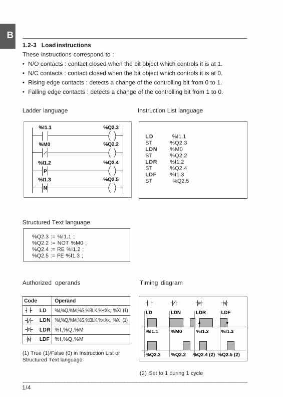
___________________________________________________________________________1/4
B1.2-3 Load instructions
These instructions correspond to :
• N/O contacts : contact closed when the bit object which controls it is at 1.
• N/C contacts : contact closed when the bit object which controls it is at 0.
• Rising edge contacts : detects a change of the controlling bit from 0 to 1.
• Falling edge contacts : detects a change of the controlling bit from 1 to 0.
Ladder language Instruction List language
LD %I1.1ST %Q2.3LDN %M0ST %Q2.2LDR %I1.2ST %Q2.4LDF %I1.3ST %Q2.5
Structured Text language
%Q2.3 := %I1.1 ;%Q2.2 := NOT %M0 ;%Q2.4 := RE %I1.2 ;%Q2.5 := FE %I1.3 ;
Authorized operands Timing diagram
Code Operand
LD %I,%Q,%M,%S,%BLK,%•:Xk, %Xi (1)
LDN %I,%Q,%M,%S,%BLK,%•:Xk, %Xi (1)
LDR %I,%Q,%M
LDF %I,%Q,%M
(1) True (1)/False (0) in Instruction List orStructured Text language
(2) Set to 1 during 1 cycle
%M0
%I1.1 %Q2.3
%I1.2
%Q2.2
%Q2.4
%I1.3 %Q2.5
P
N
P
N
%Q2.3
%I1.1
LD
%M0 %I1.2 %I1.3
LDN LDR LDF
%Q2.2 %Q2.4 (2) %Q2.5 (2)
NP
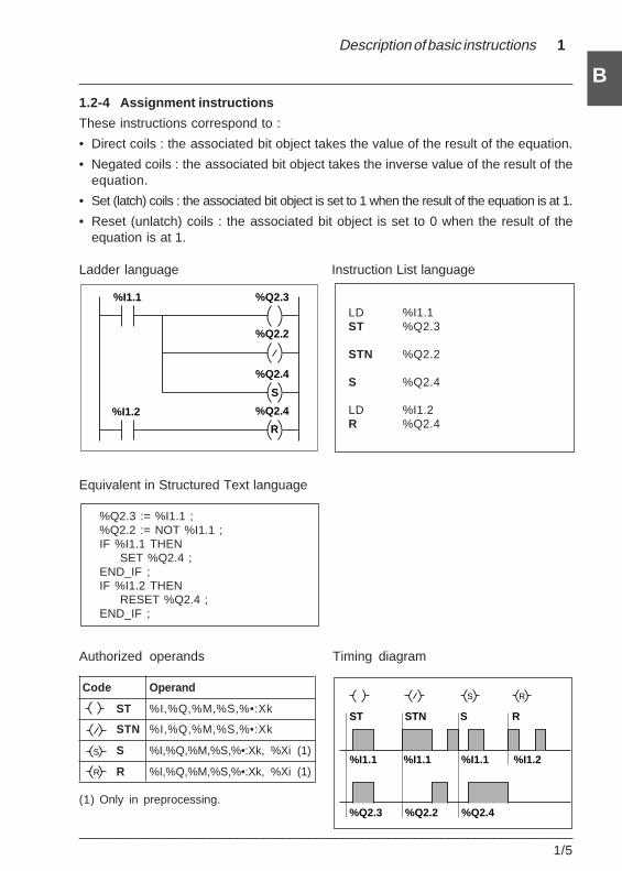
Description of basic instructions 1
___________________________________________________________________________1/5
B1.2-4 Assignment instructions
These instructions correspond to :
• Direct coils : the associated bit object takes the value of the result of the equation.
• Negated coils : the associated bit object takes the inverse value of the result of theequation.
• Set (latch) coils : the associated bit object is set to 1 when the result of the equation is at 1.
• Reset (unlatch) coils : the associated bit object is set to 0 when the result of theequation is at 1.
Ladder language Instruction List language
LD %I1.1ST %Q2.3
STN %Q2.2
S %Q2.4
LD %I1.2R %Q2.4
Equivalent in Structured Text language
%Q2.3 := %I1.1 ;%Q2.2 := NOT %I1.1 ;IF %I1.1 THEN
SET %Q2.4 ;END_IF ;IF %I1.2 THEN
RESET %Q2.4 ;END_IF ;
Authorized operands Timing diagram
Code Operand
ST %I,%Q,%M,%S,%•:Xk
STN %I,%Q,%M,%S,%•:Xk
S %I,%Q,%M,%S,%•:Xk, %Xi (1)
R %I,%Q,%M,%S,%•:Xk, %Xi (1)
(1) Only in preprocessing.%Q2.3
%I1.1
ST
%I1.1 %I1.1 %I1.2
STN S R
%Q2.2 %Q2.4
S R
%I1.1 %Q2.3
%Q2.2
%Q2.4
%I1.2 %Q2.4
S
R
S
R
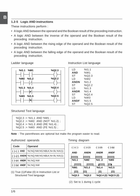
___________________________________________________________________________1/6
B1.2-5 Logic AND instructions
These instructions perform :
• A logic AND between the operand and the Boolean result of the preceding instruction.
• A logic AND between the inverse of the operand and the Boolean result of thepreceding instruction.
• A logic AND between the rising edge of the operand and the Boolean result of thepreceding instruction.
• A logic AND between the falling edge of the operand and the Boolean result of thepreceding instruction.
Ladder language Instruction List language
LD %I1.1AND %M1ST %Q2.3LD %M2ANDN %I1.2ST %Q2.2LD %I1.3ANDR %I1.4ST %Q2.4LD %M3ANDF %I1.5ST %Q2.5
Structured Text language
%Q2.3 := %I1.1 AND %M1 ;%Q2.2 := %M2 AND (NOT %I1.2) ;%Q2.4 := %I1.3 AND (RE %I1.4) ;%Q2.5 := %M3 AND (FE %I1.5) ;
Note : The parentheses are optional but make the program easier to read.
Authorized operands Timing diagram
Code Operand
AND %I,%Q,%M,%S,%BLK,%•:Xk, %Xi (1)
ANDN %I,%Q,%M,%S,%BLK,%•:Xk, %Xi (1)
ANDR %I,%Q,%M
ANDF %I,%Q,%M
(1) True (1)/False (0) in Instruction List or Structured Text language
(2) Set to 1 during 1 cycle
N
P
%M2
%I1.1 %Q2.3
%I1.3
%Q2.2
%Q2.4
%M3 %Q2.5
%I1.2
%M1
%I1.4
%I1.5
P
N
%Q2.3
%I1.1
AND
%M2 %I1 .3 %M3
ANDN ANDR ANDF
%Q2.2 %Q2.4 (2) %Q2.5 (2)
%M1 %I1.2 %I1.4 %I1.5
P N
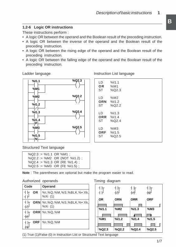
Description of basic instructions 1
___________________________________________________________________________1/7
B
%Q2.3
%I1.1
OR
%M2 %I1.3 %M3
ORN ORR ORF
%Q2.2 %Q2.4 %Q2.5
%M1 %I1.2 %I1.4 %I1.5
NP
P
1.2-6 Logic OR instructionsThese instructions perform :• A logic OR between the operand and the Boolean result of the preceding instruction.• A logic OR between the inverse of the operand and the Boolean result of the
preceding instruction.• A logic OR between the rising edge of the operand and the Boolean result of the
preceding instruction.• A logic OR between the falling edge of the operand and the Boolean result of the
preceding instruction.
Ladder language Instruction List language
LD %I1.1OR %M1ST %Q2.3
LD %M2ORN %I1.2ST %Q2.2
LD %I1.3ORR %I1.4ST %Q2.4
LD %M3ORF %I1.5ST %Q2.5
Structured Text language
%Q2.3 := %I1.1 OR %M1 ;%Q2.2 := %M2 OR (NOT %I1.2) ;%Q2.4 := %I1.3 OR (RE %I1.4) ;%Q2.5 := %M3 OR (FE %I1.5) ;
Note : The parentheses are optional but make the program easier to read.
Authorized operands Timing diagram Code Operand
OR %I,%Q,%M,%S,%BLK,%•:Xk,%Xi (1)
ORN %I,%Q,%M,%S,%BLK,%•:Xk,%Xi (1)
ORR %I,%Q,%M
ORF %I,%Q,%M
(1) True (1)/False (0) in Instruction List or Structured Text language
N
%I1.1
%M1
%Q2.3
%M2
%I1.2
%Q2.2
%I1.3
%I1.4
%Q2.4
%M3
%I1.5
%Q2.5P
N
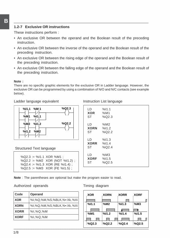
___________________________________________________________________________1/8
B
%Q2.3
%I1.1
XOR
%M2 %I1.3 %M3
XORN XORR XORF
%Q2.2 %Q2.4 %Q2.5
%M1 %I1.2 %I1.4 %I1.5
1.2-7 Exclusive OR instructions
These instructions perform :
• An exclusive OR between the operand and the Boolean result of the precedinginstruction.
• An exclusive OR between the inverse of the operand and the Boolean result of thepreceding instruction.
• An exclusive OR between the rising edge of the operand and the Boolean result ofthe preceding instruction.
• An exclusive OR between the falling edge of the operand and the Boolean result ofthe preceding instruction.
Note :There are no specific graphic elements for the exclusive OR in Ladder language. However, theexclusive OR can be programmed by using a combination of N/O and N/C contacts (see examplebelow).
Ladder language equivalent Instruction List language
LD %I1.1XOR %M1ST %Q2.3
LD %M2XORN %I1.2ST %Q2.2
LD %I1.3XORR %I1.4ST %Q2.4
LD %M3XORF %I1.5ST %Q2.5
Note : The parentheses are optional but make the program easier to read.
Authorized operands Timing diagram
Code Operand
XOR %I,%Q,%M,%S,%BLK,%•:Xk, %Xi
XORN %I,%Q,%M,%S,%BLK,%•:Xk, %Xi
XORR %I,%Q,%M
XORF %I,%Q,%M
Structured Text language
%Q2.3 := %I1.1 XOR %M1 ;%Q2.2 := %M2 XOR (NOT %I1.2) ;%Q2.4 := %I1.3 XOR (RE %I1.4) ;%Q2.5 := %M3 XOR (FE %I1.5) ;
%I1.1
%M1
%Q2.3
%M2
%I1.2
%Q2.2
%M 1
%I1.1
%I1.2
%M2
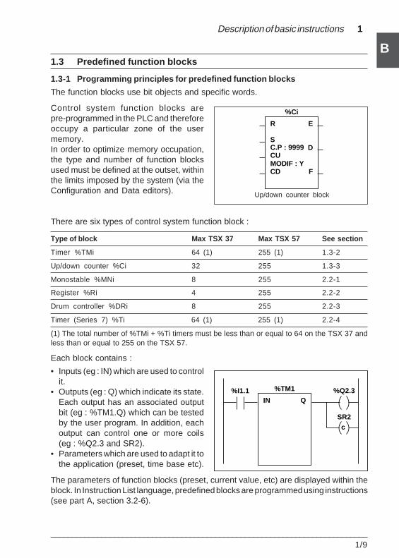
Description of basic instructions 1
___________________________________________________________________________1/9
B1.3 Predefined function blocks
1.3-1 Programming principles for predefined function blocks
The function blocks use bit objects and specific words.
Control system function blocks arepre-programmed in the PLC and thereforeoccupy a particular zone of the usermemory.In order to optimize memory occupation,the type and number of function blocksused must be defined at the outset, withinthe limits imposed by the system (via theConfiguration and Data editors).
There are six types of control system function block :
Type of block Max TSX 37 Max TSX 57 See section
Timer %TMi 64 (1) 255 (1) 1.3-2
Up/down counter %Ci 32 255 1.3-3
Monostable %MNi 8 255 2.2-1
Register %Ri 4 255 2.2-2
Drum controller %DRi 8 255 2.2-3
Timer (Series 7) %Ti 64 (1) 255 (1) 2.2-4
(1) The total number of %TMi + %Ti timers must be less than or equal to 64 on the TSX 37 andless than or equal to 255 on the TSX 57.
Each block contains :
• Inputs (eg : IN) which are used to controlit.
• Outputs (eg : Q) which indicate its state.Each output has an associated outputbit (eg : %TM1.Q) which can be testedby the user program. In addition, eachoutput can control one or more coils(eg : %Q2.3 and SR2).
• Parameters which are used to adapt it tothe application (preset, time base etc).
The parameters of function blocks (preset, current value, etc) are displayed within theblock. In Instruction List language, predefined blocks are programmed using instructions(see part A, section 3.2-6).
Up/down counter block
R
S
CU
CD F
D
E
%Ci
C.P : 9999
MODIF : Y
%Q2.3%I1.1IN Q
%TM1
SR2c
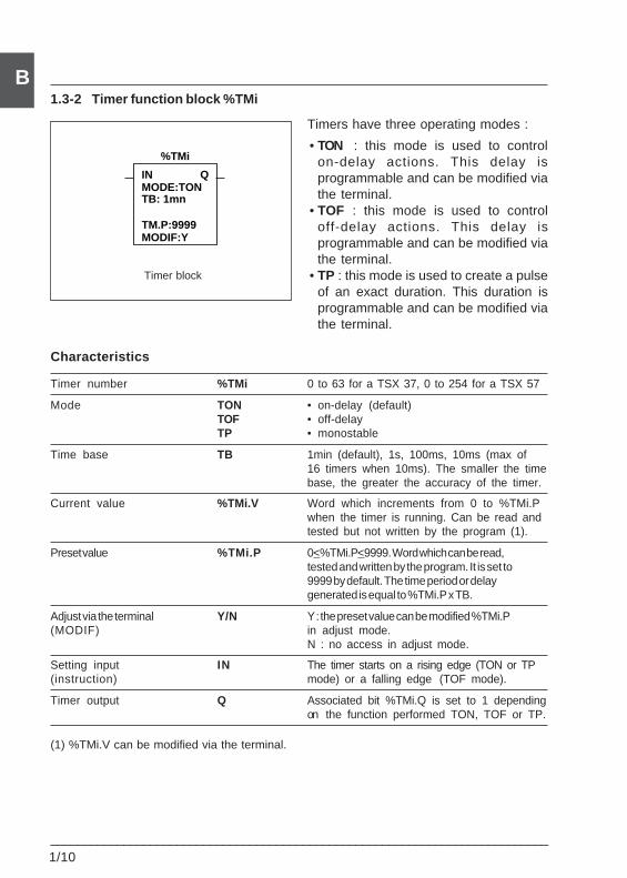
___________________________________________________________________________1/10
B1.3-2 Timer function block %TMi
Timers have three operating modes :
• TON : this mode is used to controlon-delay actions. This delay isprogrammable and can be modified viathe terminal.
• TOF : this mode is used to controloff-delay actions. This delay isprogrammable and can be modified viathe terminal.
• TP : this mode is used to create a pulseof an exact duration. This duration isprogrammable and can be modified viathe terminal.
Characteristics
Timer number %TMi 0 to 63 for a TSX 37, 0 to 254 for a TSX 57
Mode TON • on-delay (default)TOF • off-delayTP • monostable
Time base TB 1min (default), 1s, 100ms, 10ms (max of16 timers when 10ms). The smaller the timebase, the greater the accuracy of the timer.
Current value %TMi.V Word which increments from 0 to %TMi.Pwhen the timer is running. Can be read andtested but not written by the program (1).
Preset value %TMi.P 0<%TMi.P<9999. Word which can be read,tested and written by the program. It is set to9999 by default. The time period or delaygenerated is equal to %TMi.P x TB.
Adjust via the terminal Y/N Y : the preset value can be modified %TMi.P(MODIF) in adjust mode.
N : no access in adjust mode.
Setting input IN The timer starts on a rising edge (TON or TP(instruction) mode) or a falling edge (TOF mode).
Timer output Q Associated bit %TMi.Q is set to 1 dependingon the function performed TON, TOF or TP.
(1) %TMi.V can be modified via the terminal.
Timer block
INMODE:TON
MODIF:Y
Q
%TMi
TB: 1mn
TM.P:9999
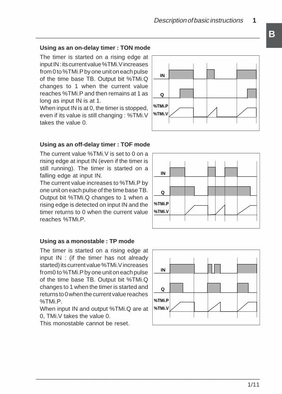
Description of basic instructions 1
___________________________________________________________________________1/11
BUsing as an on-delay timer : TON mode
The timer is started on a rising edge atinput IN : its current value %TMi.V increasesfrom 0 to %TMi.P by one unit on each pulseof the time base TB. Output bit %TMi.Qchanges to 1 when the current valuereaches %TMi.P and then remains at 1 aslong as input IN is at 1.When input IN is at 0, the timer is stopped,even if its value is still changing : %TMi.Vtakes the value 0.
Using as an off-delay timer : TOF mode
The current value %TMi.V is set to 0 on arising edge at input IN (even if the timer isstill running). The timer is started on afalling edge at input IN.The current value increases to %TMi.P byone unit on each pulse of the time base TB.Output bit %TMi.Q changes to 1 when arising edge is detected on input IN and thetimer returns to 0 when the current valuereaches %TMi.P.
Using as a monostable : TP mode
The timer is started on a rising edge atinput IN : (if the timer has not alreadystarted) its current value %TMi.V increasesfrom 0 to %TMi.P by one unit on each pulseof the time base TB. Output bit %TMi.Qchanges to 1 when the timer is started andreturns to 0 when the current value reaches%TMi.P.When input IN and output %TMi.Q are at0, TMi.V takes the value 0.This monostable cannot be reset.
IN
Q
%TMi.V
%TMi.P
IN
Q
%TMi.V
%TMi.P
IN
Q
%TMi.V
%TMi.P
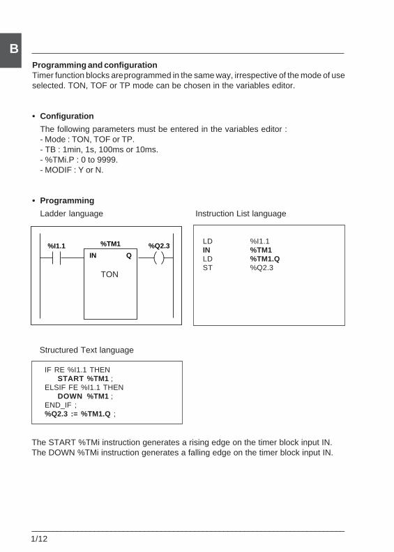
___________________________________________________________________________1/12
BProgramming and configurationTimer function blocks are programmed in the same way, irrespective of the mode of useselected. TON, TOF or TP mode can be chosen in the variables editor.
• Configuration
The following parameters must be entered in the variables editor :- Mode : TON, TOF or TP.- TB : 1min, 1s, 100ms or 10ms.- %TMi.P : 0 to 9999.- MODIF : Y or N.
• Programming
Ladder language Instruction List language
LD %I1.1IN %TM1LD %TM1.QST %Q2.3
Structured Text language
IF RE %I1.1 THENSTART %TM1 ;
ELSIF FE %I1.1 THENDOWN %TM1 ;
END_IF ;%Q2.3 := %TM1.Q ;
The START %TMi instruction generates a rising edge on the timer block input IN.The DOWN %TMi instruction generates a falling edge on the timer block input IN.
TON
%Q2.3%I1.1IN Q
%TM1
Description of basic instructions 1
___________________________________________________________________________1/13
BSpecial cases
• Effect of a cold restart : (%S0=1) forces the current value to 0, sets output %TMi.Qto 0 and the preset value is reset to the value defined during configuration.
• Effect of a warm restart : (%S1=1) has no effect on the current value of the timernor on the preset value. The current value does not change during a power outage.
• Effect of a PLC stop, de-activation of a task or execution of a break point : doesnot freeze the current value.
• Effect of a program jump : the fact of not scanning the instructions where the timerblock is programmed does not freeze the current value %TMi.V, which continues toincrement to %TMi.P. Similarly, bit %TMi.Q associated with output Q of the timer blockmaintains its normal operation and can thus be tested by another instruction.However, the output wired directly to the block output is neither activated nor scannedby the PLC.
• Testing bit %TMi.Q : it is advisable to test bit %TMi.Q once only in the program.
• Effect of modifying the preset %TMi.P : modifying the preset value via an instructionor in adjust mode only takes effect when the timer is next activated : modifying thepreset value in the variables editor is only taken into account after a cold restart(%S0=1).
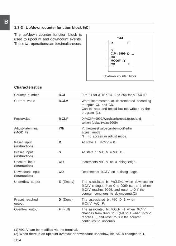
___________________________________________________________________________1/14
B1.3-3 Up/down counter function block %Ci
The up/down counter function block isused to upcount and downcount events.These two operations can be simultaneous.
Characteristics
Counter number %Ci 0 to 31 for a TSX 37, 0 to 254 for a TSX 57
Current value %Ci.V Word incremented or decremented accordingto inputs CU and CD.Can be read and tested but not written by theprogram (1).
Preset value %Ci.P 0<%Ci.P<9999. Word can be read, tested andwritten. (default value 9999)
Adjust via terminal Y/N Y : the preset value can be modified in(MODIF) adjust mode.
N : no access in adjust mode.
Reset input R At state 1 : %Ci.V = 0.(instruction)
Preset input S At state 1: %Ci.V = %Ci.P.(instruction)
Upcount input CU Increments %Ci.V on a rising edge.(instruction)
Downcount input CD Decrements %Ci.V on a rising edge.(instruction)
Underflow output E (Empty) The associated bit %Ci.E=1 when downcounter%Ci.V changes from 0 to 9999 (set to 1 when%Ci.V reaches 9999, and reset to 0 if thecounter continues to downcount).(2)
Preset reached D (Done) The associated bit %Ci.D=1 whenoutput %Ci.V=%Ci.P.
Overflow output F (Full) The associated bit %Ci.F =1 when %Ci.Vchanges from 9999 to 0 (set to 1 when %Ci.Vreaches 0, and reset to 0 if the countercontinues to upcount).
(1) %Ci.V can be modified via the terminal.(2) When there is an upcount overflow or downcount underflow, bit %S18 changes to 1.
Up/down counter block
R
S
CU
CD F
D
E
%Ci
C.P : 9999
MODIF : Y
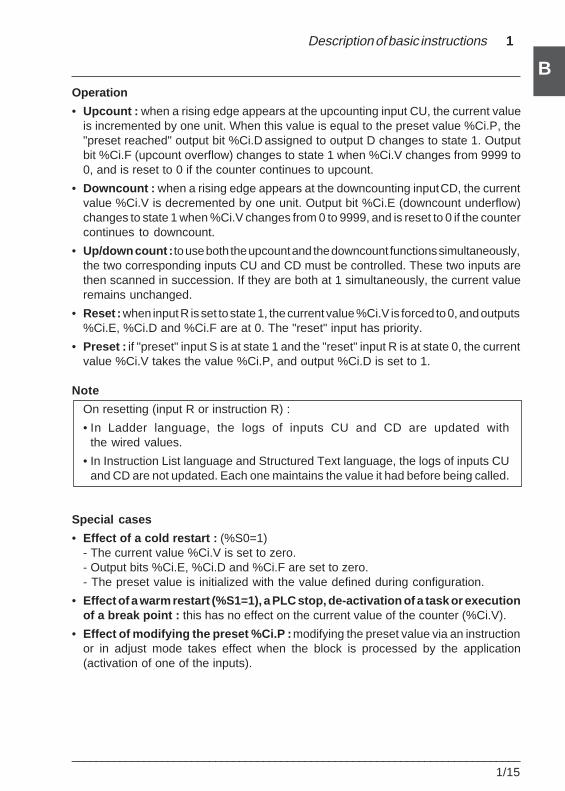
Description of basic instructions 1
___________________________________________________________________________1/15
BOperation
• Upcount : when a rising edge appears at the upcounting input CU, the current valueis incremented by one unit. When this value is equal to the preset value %Ci.P, the"preset reached" output bit %Ci.D assigned to output D changes to state 1. Outputbit %Ci.F (upcount overflow) changes to state 1 when %Ci.V changes from 9999 to0, and is reset to 0 if the counter continues to upcount.
• Downcount : when a rising edge appears at the downcounting input CD, the currentvalue %Ci.V is decremented by one unit. Output bit %Ci.E (downcount underflow)changes to state 1 when %Ci.V changes from 0 to 9999, and is reset to 0 if the countercontinues to downcount.
• Up/down count : to use both the upcount and the downcount functions simultaneously,the two corresponding inputs CU and CD must be controlled. These two inputs arethen scanned in succession. If they are both at 1 simultaneously, the current valueremains unchanged.
• Reset : when input R is set to state 1, the current value %Ci.V is forced to 0, and outputs%Ci.E, %Ci.D and %Ci.F are at 0. The "reset" input has priority.
• Preset : if "preset" input S is at state 1 and the "reset" input R is at state 0, the currentvalue %Ci.V takes the value %Ci.P, and output %Ci.D is set to 1.
Note
On resetting (input R or instruction R) :
• In Ladder language, the logs of inputs CU and CD are updated withthe wired values.
• In Instruction List language and Structured Text language, the logs of inputs CUand CD are not updated. Each one maintains the value it had before being called.
Special cases
• Effect of a cold restart : (%S0=1)- The current value %Ci.V is set to zero.- Output bits %Ci.E, %Ci.D and %Ci.F are set to zero.- The preset value is initialized with the value defined during configuration.
• Effect of a warm restart (%S1=1), a PLC stop, de-activation of a task or executionof a break point : this has no effect on the current value of the counter (%Ci.V).
• Effect of modifying the preset %Ci.P : modifying the preset value via an instructionor in adjust mode takes effect when the block is processed by the application(activation of one of the inputs).
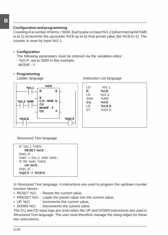
___________________________________________________________________________1/16
BConfiguration and programmingCounting of a number of items = 5000. Each pulse on input %I1.2 (when internal bit %M0is at 1) increments the upcounter %C8 up to its final preset value (bit %C8.D=1). Thecounter is reset by input %I1.1.
• ConfigurationThe following parameters must be entered via the variables editor :- %Ci.P, set to 5000 in this example,- MODIF : Y.
• ProgrammingLadder language Instruction List language
LD %I1.1R %C8LD %I1.2AND %M0CU %C8LD %C8.DST %Q2.0
Structured Text language
IF %I1.1 THENRESET %C8 ;
END_IF ;%M1 := %I1.2 AND %M0 ;IF RE %M1 THEN
UP %C8 ;END_IF ;%Q2.0 := %C8.D;
In Structured Text language, 4 instructions are used to program the up/down counterfunction blocks :• RESET %Ci : Resets the current value,• PRESET %Ci : Loads the preset value into the current value,• UP %Ci : Increments the current value,• DOWN %Ci : Decrements the current value.The CU and CD input logs are reset when the UP and DOWN instructions are used inStructured Text language. The user must therefore manage the rising edges for thesetwo instructions.
%I1.2
%C8.D
%I1.1
%Q2.0
%M0
R
S
CU
CD F
D
E
%C8
C.P : 5000
MODIF : Y
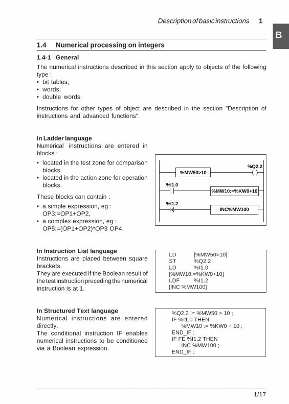
Description of basic instructions 1
___________________________________________________________________________1/17
B1.4 Numerical processing on integers
1.4-1 General
The numerical instructions described in this section apply to objects of the followingtype :• bit tables,• words,• double words.
Instructions for other types of object are described in the section "Description ofinstructions and advanced functions".
In Ladder languageNumerical instructions are entered inblocks :
• located in the test zone for comparisonblocks.
• located in the action zone for operationblocks.
These blocks can contain :
• a simple expression, eg :OP3:=OP1+OP2,
• a complex expression, eg :OP5:=(OP1+OP2)*OP3-OP4.
In Instruction List languageInstructions are placed between squarebrackets.They are executed if the Boolean result ofthe test instruction preceding the numericalinstruction is at 1.
In Structured Text languageNumerical instructions are entereddirectly.The conditional instruction IF enablesnumerical instructions to be conditionedvia a Boolean expression.
LD [%MW50>10]ST %Q2.2LD %I1.0[%MW10:=%KW0+10]LDF %I1.2[INC %MW100]
%Q2.2 := %MW50 > 10 ;IF %I1.0 THEN
%MW10 := %KW0 + 10 ;END_IF ;IF FE %I1.2 THEN
INC %MW100 ;END_IF ;
%MW50>10
%MW10:=%KW0+10
INC%MW100N
%I1.2
%I1.0
%Q2.2
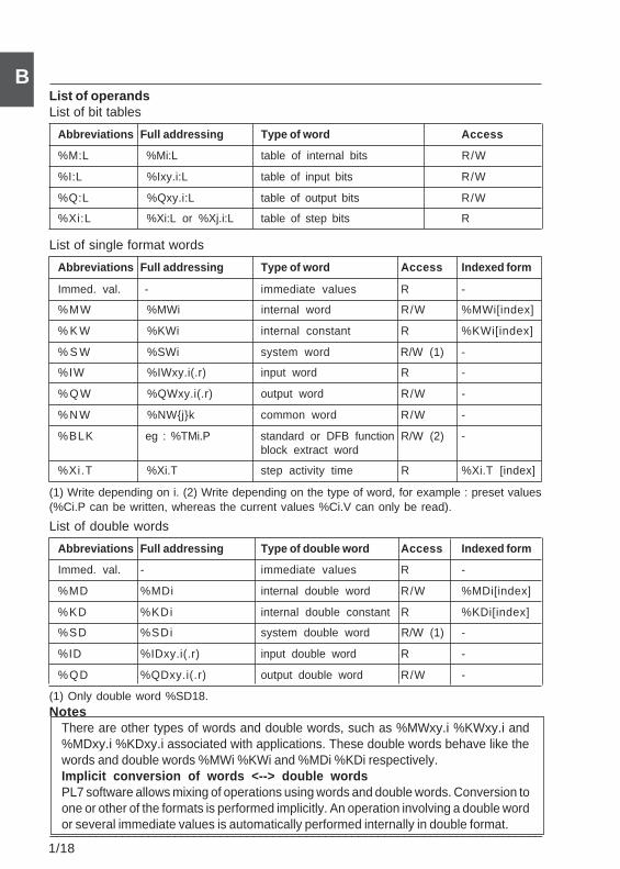
___________________________________________________________________________1/18
BList of operandsList of bit tables
Abbreviations Full addressing Type of word Access
%M:L %Mi:L table of internal bits R/W
%I:L %Ixy.i:L table of input bits R/W
%Q:L %Qxy.i:L table of output bits R/W
%Xi:L %Xi:L or %Xj.i:L table of step bits R
List of single format words
Abbreviations Full addressing Type of word Access Indexed form
Immed. val. - immediate values R -
%MW %MWi internal word R/W %MWi[index]
% K W %KWi internal constant R %KWi[index]
% S W %SWi system word R/W (1) -
%IW %IWxy.i(.r) input word R -
% Q W %QWxy.i(.r) output word R/W -
% N W %NW{j}k common word R/W -
%BLK eg : %TMi.P standard or DFB function R/W (2) -block extract word
%Xi.T %Xi.T step activity time R %Xi.T [index]
(1) Write depending on i. (2) Write depending on the type of word, for example : preset values(%Ci.P can be written, whereas the current values %Ci.V can only be read).
List of double words
Abbreviations Full addressing Type of double word Access Indexed form
Immed. val. - immediate values R -
%MD %MDi internal double word R/W %MDi[index]
%KD %KDi internal double constant R %KDi[index]
%SD %SDi system double word R/W (1) -
%ID %IDxy.i(.r) input double word R -
%QD %QDxy.i(.r) output double word R/W -
(1) Only double word %SD18.Notes
There are other types of words and double words, such as %MWxy.i %KWxy.i and%MDxy.i %KDxy.i associated with applications. These double words behave like thewords and double words %MWi %KWi and %MDi %KDi respectively.Implicit conversion of words <--> double wordsPL7 software allows mixing of operations using words and double words. Conversion toone or other of the formats is performed implicitly. An operation involving a double wordor several immediate values is automatically performed internally in double format.
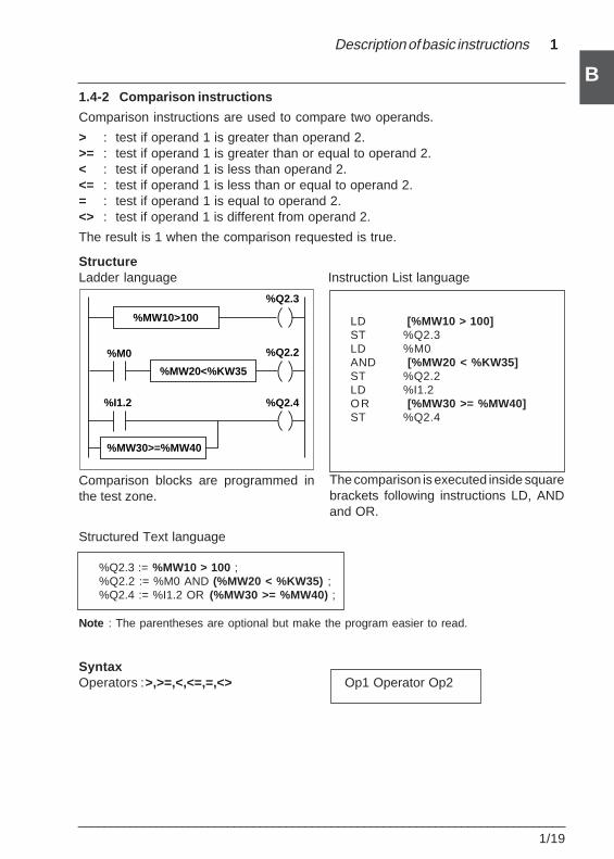
Description of basic instructions 1
___________________________________________________________________________1/19
B1.4-2 Comparison instructions
Comparison instructions are used to compare two operands.
> : test if operand 1 is greater than operand 2.>= : test if operand 1 is greater than or equal to operand 2.< : test if operand 1 is less than operand 2.<= : test if operand 1 is less than or equal to operand 2.= : test if operand 1 is equal to operand 2.<> : test if operand 1 is different from operand 2.
The result is 1 when the comparison requested is true.
StructureLadder language Instruction List language
Comparison blocks are programmed inthe test zone.
Structured Text language
%Q2.3 := %MW10 > 100 ;%Q2.2 := %M0 AND (%MW20 < %KW35) ;%Q2.4 := %I1.2 OR (%MW30 >= %MW40) ;
Note : The parentheses are optional but make the program easier to read.
SyntaxOperators : >,>=,<,<=,=,<> Op1 Operator Op2
LD [%MW10 > 100]ST %Q2.3LD %M0AND [%MW20 < %KW35]ST %Q2.2LD %I1.2OR [%MW30 >= %MW40]ST %Q2.4
The comparison is executed inside squarebrackets following instructions LD, ANDand OR.
%M0
%I1.2
%MW10>100
%MW20<%KW35
%MW30>=%MW40
%Q2.3
%Q2.2
%Q2.4
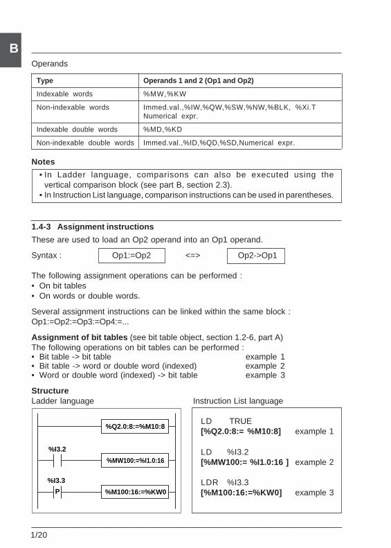
___________________________________________________________________________1/20
B
1.4-3 Assignment instructions
These are used to load an Op2 operand into an Op1 operand.
Syntax : Op1:=Op2 <=> Op2->Op1
The following assignment operations can be performed :• On bit tables• On words or double words.
Several assignment instructions can be linked within the same block :Op1:=Op2:=Op3:=Op4:=...
Assignment of bit tables (see bit table object, section 1.2-6, part A)The following operations on bit tables can be performed :• Bit table -> bit table example 1• Bit table -> word or double word (indexed) example 2• Word or double word (indexed) -> bit table example 3
StructureLadder language Instruction List language
LD TRUE[%Q2.0:8:= %M10:8] example 1
LD %I3.2[%MW100:= %I1.0:16 ] example 2
LDR %I3.3[%M100:16:=%KW0] example 3
Operands
Type Operands 1 and 2 (Op1 and Op2)
Indexable words %MW,%KW
Non-indexable words Immed.val.,%IW,%QW,%SW,%NW,%BLK, %Xi.TNumerical expr.
Indexable double words %MD,%KD
Non-indexable double words Immed.val.,%ID,%QD,%SD,Numerical expr.
Notes
• In Ladder language, comparisons can also be executed using thevertical comparison block (see part B, section 2.3).
• In Instruction List language, comparison instructions can be used in parentheses.
%I3.2
%I3.3
%Q2.0:8:=%M10:8
%MW100:=%I1.0:16
%M100:16:=%KW0P
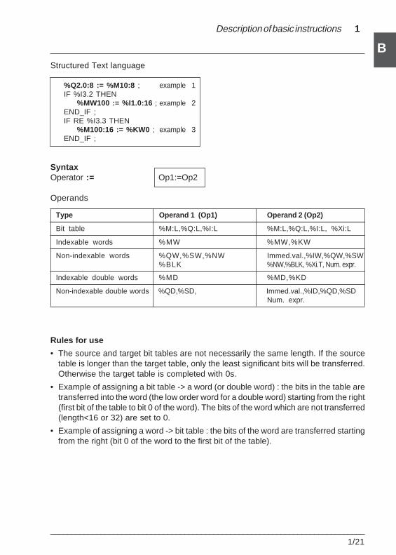
Description of basic instructions 1
___________________________________________________________________________1/21
BStructured Text language
%Q2.0:8 := %M10:8 ; example 1IF %I3.2 THEN
%MW100 := %I1.0:16 ; example 2END_IF ;IF RE %I3.3 THEN
%M100:16 := %KW0 ; example 3END_IF ;
SyntaxOperator := Op1:=Op2
Operands
Type Operand 1 (Op1) Operand 2 (Op2)
Bit table %M:L,%Q:L,%I:L %M:L,%Q:L,%I:L, %Xi:L
Indexable words %MW %MW,%KW
Non-indexable words %QW,%SW,%NW Immed.val.,%IW,%QW,%SW%BLK %NW,%BLK, %Xi.T, Num. expr.
Indexable double words %MD %MD,%KD
Non-indexable double words %QD,%SD, Immed.val.,%ID,%QD,%SDNum. expr.
Rules for use
• The source and target bit tables are not necessarily the same length. If the sourcetable is longer than the target table, only the least significant bits will be transferred.Otherwise the target table is completed with 0s.
• Example of assigning a bit table -> a word (or double word) : the bits in the table aretransferred into the word (the low order word for a double word) starting from the right(first bit of the table to bit 0 of the word). The bits of the word which are not transferred(length<16 or 32) are set to 0.
• Example of assigning a word -> bit table : the bits of the word are transferred startingfrom the right (bit 0 of the word to the first bit of the table).
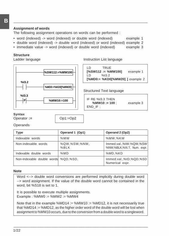
___________________________________________________________________________1/22
BAssignment of wordsThe following assignment operations on words can be performed :
• word (indexed) -> word (indexed) or double word (indexed) example 1• double word (indexed) -> double word (indexed) or word (indexed) example 2• immediate value -> word (indexed) or double word (indexed) example 3
StructureLadder language Instruction List language
LD TRUE[%SW112 := %MW100] example 1LD %I3.2[%MD0:= %KD0[%MW20] ] example 2
Structured Text language
IF RE %I3.3 THEN%MW10 := 100 ; example 3
END_IF ;
SyntaxOperator := Op1:=Op2
Operands
Type Operand 1 (Op1) Operand 2 (Op2)
Indexable words %MW %MW,%KW
Non-indexable words %QW,%SW,%NW, Immed.val.,%IW,%QW,%SW%BLK %NW,%BLK,%Xi.T, Num. expr.
Indexable double words %MD %MD,%KD
Non-indexable double words %QD,%SD, Immed.val.,%ID,%QD,%SDNumerical expr.
Note
Word <--> double word conversions are performed implicitly during double word--> word assignment. If the value of the double word cannot be contained in theword, bit %S18 is set to 1.
It is possible to execute multiple assignments.Example : %MW0 := %MW2 := %MW4
Note that in the example %MD14 := %MW10 := %MD12, it is not necessarily truethat %MD14 := %MD12, as the higher order word of the double word will be lost whenassignment to %MW10 occurs, due to the conversion from a double word to a single word.
%I3.2
%I3.3
%SW112:=%MW100
%MD0:=%KD0[%MW20]
%MW10:=100P
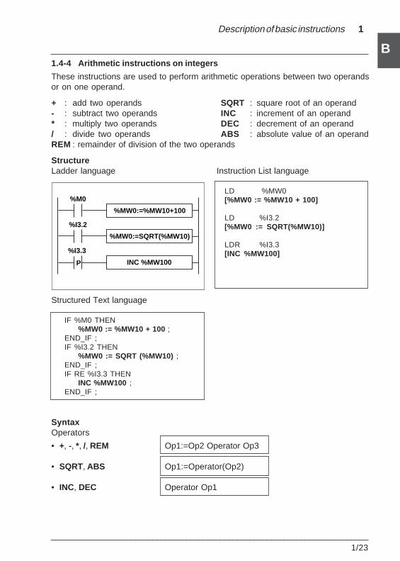
Description of basic instructions 1
___________________________________________________________________________1/23
B1.4-4 Arithmetic instructions on integers
These instructions are used to perform arithmetic operations between two operandsor on one operand.
+ : add two operands SQRT : square root of an operand- : subtract two operands INC : increment of an operand* : multiply two operands DEC : decrement of an operand/ : divide two operands ABS : absolute value of an operandREM : remainder of division of the two operands
StructureLadder language Instruction List language
LD %MW0[%MW0 := %MW10 + 100]
LD %I3.2[%MW0 := SQRT(%MW10)]
LDR %I3.3[INC %MW100]
Structured Text language
IF %M0 THEN%MW0 := %MW10 + 100 ;
END_IF ;IF %I3.2 THEN
%MW0 := SQRT (%MW10) ;END_IF ;IF RE %I3.3 THEN
INC %MW100 ;END_IF ;
SyntaxOperators
• +, -, *, /, REM Op1:=Op2 Operator Op3
• SQRT, ABS Op1:=Operator(Op2)
• INC, DEC Operator Op1
%I3.2
%I3.3
%MW0:=%MW10+100
%MW0:=SQRT(%MW10)
INC %MW100
%M0
P
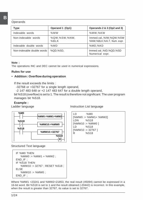
___________________________________________________________________________1/24
B
If the result exceeds the limits :-32768 or +32767 for a single length operand,-2 147 483 648 or +2 147 483 647 for a double length operand,
bit %S18 (overflow) is set to 1. The result is therefore not significant. The user programmanages bit %S18.
Example :Ladder language Instruction List language
LD %M0[%MW0 := %MW1+ %MW2]LDN %S18[%MW10 := %MW0 ]LD %S18[%MW10 := 32767 ]R %S18
Structured Text language
IF %M0 THEN%MW0 := %MW1 + %MW2 ;
END_IF ;IF %S18 THEN
%MW10 := 32767 ; RESET %S18 ;ELSE
%MW10 := %MW0 ;END_IF ;
Where %MW1 =23241 and %MW2=21853, the real result (45094) cannot be expressed in a16-bit word. Bit %S18 is set to 1 and the result obtained (-20442) is incorrect. In this example,when the result is greater than 32767, its value is set to 32767.
Operands
Type Operand 1 (Op1) Operands 2 & 3 (Op2 and 3)
Indexable words %MW %MW,%KW
Non-indexable words %QW,%SW,%NW, Immed.val.,%IW,%QW,%SW%BLK %NW,%BLK,%Xi.T, Num. expr.
Indexable double words %MD %MD,%KD
Non-indexable double words %QD,%SD, Immed.val.,%ID,%QD,%SDNumerical expr.
Note :The operations INC and DEC cannot be used in numerical expressions.
Rules for use
• Addition : Overflow during operation
%S18
%S18
%MW0:=%MW1+%MW2
%MW10:=%MW0
%MW10:=32767
%M0
%S18R
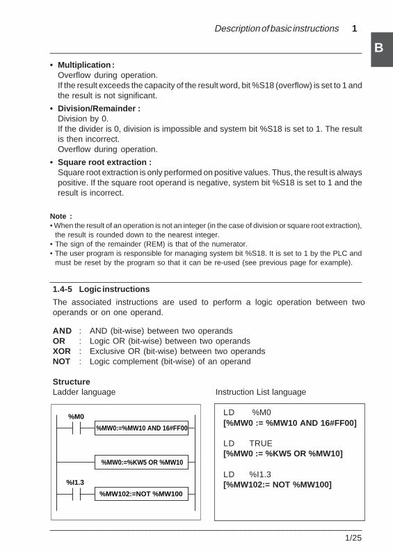
Description of basic instructions 1
___________________________________________________________________________1/25
B
1.4-5 Logic instructions
The associated instructions are used to perform a logic operation between twooperands or on one operand.
AND : AND (bit-wise) between two operandsOR : Logic OR (bit-wise) between two operandsXOR : Exclusive OR (bit-wise) between two operandsNOT : Logic complement (bit-wise) of an operand
StructureLadder language Instruction List language
LD %M0[%MW0 := %MW10 AND 16#FF00]
LD TRUE[%MW0 := %KW5 OR %MW10]
LD %I1.3[%MW102:= NOT %MW100]
• Multiplication :Overflow during operation.If the result exceeds the capacity of the result word, bit %S18 (overflow) is set to 1 andthe result is not significant.
• Division/Remainder :Division by 0.If the divider is 0, division is impossible and system bit %S18 is set to 1. The resultis then incorrect.Overflow during operation.
• Square root extraction :Square root extraction is only performed on positive values. Thus, the result is alwayspositive. If the square root operand is negative, system bit %S18 is set to 1 and theresult is incorrect.
Note :• When the result of an operation is not an integer (in the case of division or square root extraction),
the result is rounded down to the nearest integer.• The sign of the remainder (REM) is that of the numerator.• The user program is responsible for managing system bit %S18. It is set to 1 by the PLC and
must be reset by the program so that it can be re-used (see previous page for example).
%I1.3
%MW0:=%MW10 AND 16#FF00
%MW0:=%KW5 OR %MW10
%MW102:=NOT %MW100
%M0
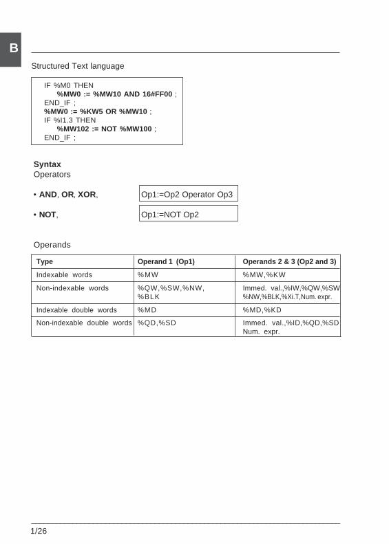
___________________________________________________________________________1/26
BStructured Text language
IF %M0 THEN%MW0 := %MW10 AND 16#FF00 ;
END_IF ;%MW0 := %KW5 OR %MW10 ;IF %I1.3 THEN
%MW102 := NOT %MW100 ;END_IF ;
SyntaxOperators
• AND, OR, XOR, Op1:=Op2 Operator Op3
• NOT, Op1:=NOT Op2
Operands
Type Operand 1 (Op1) Operands 2 & 3 (Op2 and 3)
Indexable words %MW %MW,%KW
Non-indexable words %QW,%SW,%NW, Immed. val.,%IW,%QW,%SW%BLK %NW,%BLK,%Xi.T,Num. expr.
Indexable double words %MD %MD,%KD
Non-indexable double words %QD,%SD Immed. val.,%ID,%QD,%SDNum. expr.
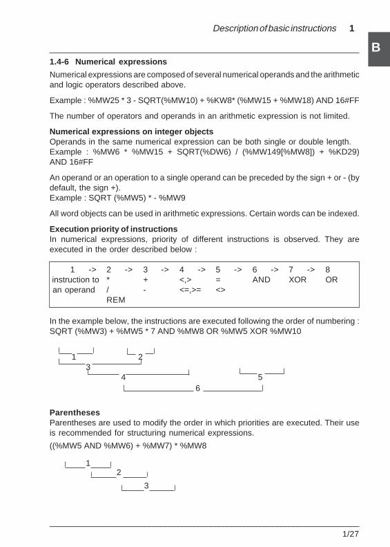
Description of basic instructions 1
___________________________________________________________________________1/27
B1.4-6 Numerical expressions
Numerical expressions are composed of several numerical operands and the arithmeticand logic operators described above.
Example : %MW25 * 3 - SQRT(%MW10) + %KW8* (%MW15 + %MW18) AND 16#FF
The number of operators and operands in an arithmetic expression is not limited.
Numerical expressions on integer objectsOperands in the same numerical expression can be both single or double length.Example : %MW6 * %MW15 + SQRT(%DW6) / (%MW149[%MW8]) + %KD29)AND 16#FF
An operand or an operation to a single operand can be preceded by the sign + or - (bydefault, the sign +).Example : SQRT (%MW5) * - %MW9
All word objects can be used in arithmetic expressions. Certain words can be indexed.
Execution priority of instructionsIn numerical expressions, priority of different instructions is observed. They areexecuted in the order described below :
1 -> 2 -> 3 -> 4 -> 5 -> 6 -> 7 -> 8 instruction to * + <,> = AND XOR OR an operand / - <=,>= <>
REM
In the example below, the instructions are executed following the order of numbering :SQRT (%MW3) + %MW5 * 7 AND %MW8 OR %MW5 XOR %MW10
1 23
4 5
ParenthesesParentheses are used to modify the order in which priorities are executed. Their useis recommended for structuring numerical expressions.
((%MW5 AND %MW6) + %MW7) * %MW8
6
2
3
1
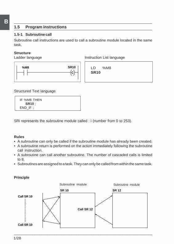
___________________________________________________________________________1/28
B1.5 Program instructions
1.5-1 Subroutine call
Subroutine call instructions are used to call a subroutine module located in the sametask.
StructureLadder language Instruction List language
Structured Text language
IF %M8 THENSR10 ;
END_IF ;
SRi represents the subroutine module called : i (number from 0 to 253).
Rules• A subroutine can only be called if the subroutine module has already been created.• A subroutine return is performed on the action immediately following the subroutine
call instruction.• A subroutine can call another subroutine. The number of cascaded calls is limited
to 8.• Subroutines are assigned to a task. They can only be called from within the same task.
Principle
LD %M8SR10
Subroutine module Subroutine module
SR 10 SR 12
Call SR 12
Call SR 10
Call SR 10
%M8 SR10
C
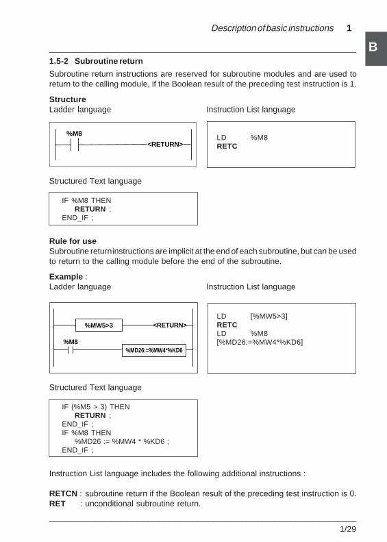
Description of basic instructions 1
___________________________________________________________________________1/29
B1.5-2 Subroutine return
Subroutine return instructions are reserved for subroutine modules and are used toreturn to the calling module, if the Boolean result of the preceding test instruction is 1.
StructureLadder language Instruction List language
LD %M8RETC
Structured Text language
IF %M8 THENRETURN ;
END_IF ;
Rule for useSubroutine return instructions are implicit at the end of each subroutine, but can be usedto return to the calling module before the end of the subroutine.
Example :Ladder language Instruction List language
LD [%MW5>3]RETCLD %M8[%MD26:=%MW4*%KD6]
Structured Text language
IF (%M5 > 3) THENRETURN ;
END_IF ;IF %M8 THEN
%MD26 := %MW4 * %KD6 ;END_IF ;
Instruction List language includes the following additional instructions :
RETCN : subroutine return if the Boolean result of the preceding test instruction is 0.RET : unconditional subroutine return.
%M8
<RETURN>
%MW5>3
%MD26:=%MW4*%KD6%M8
<RETURN>
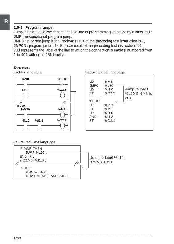
___________________________________________________________________________1/30
B1.5-3 Program jumpsJump instructions allow connection to a line of programming identified by a label %Li :JMP : unconditional program jump,JMPC : program jump if the Boolean result of the preceding test instruction is 1,JMPCN : program jump if the Boolean result of the preceding test instruction is 0,%Li represents the label of the line to which the connection is made (i numbered from1 to 999 with up to 256 labels).
StructureLadder language Instruction List language
LD %M8JMPC %L10LD %I1.0ST %Q2.5..............%L10 :LD %M20ST %M5LD %I1.0AND %I1.2ST %Q2.1
Structured Text language
IF %M8 THENJUMP %L10 ;
END_IF ;%Q2.5 := %I1.0 ;
%L10 :%M5 := %M20 ;%Q2.1 := %I1.0 AND %I1.2 ;
Jump to label%L10 if %M8 isat 1.
Jump to label %L10,if %M8 is at 1.
%I1.0
%L10
%Q2.5
>>
%M8
%I1.0
%M5
%Q2.1
%M20%L10
%I1.2
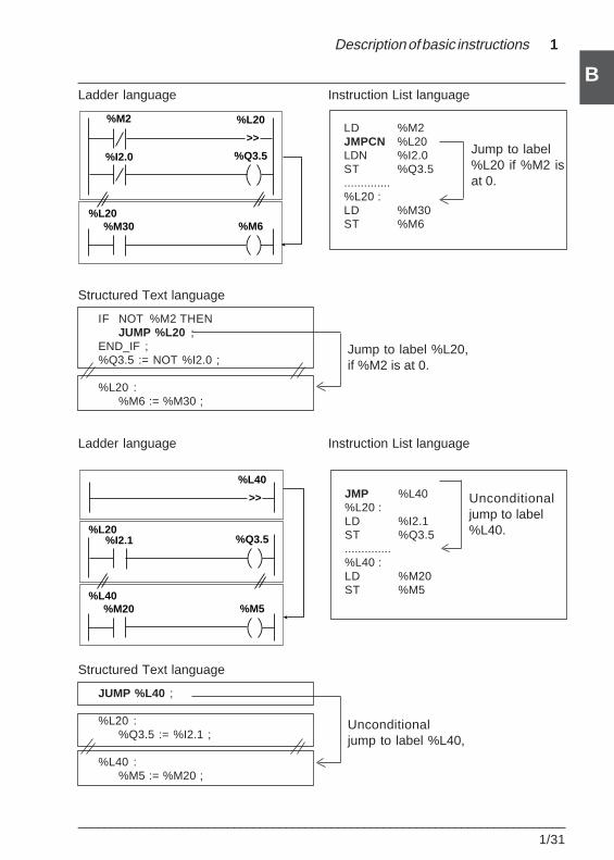
Description of basic instructions 1
___________________________________________________________________________1/31
B
LD %M2JMPCN %L20LDN %I2.0ST %Q3.5..............%L20 :LD %M30ST %M6
Structured Text language
IF NOT %M2 THENJUMP %L20 ;
END_IF ;%Q3.5 := NOT %I2.0 ;
%L20 :%M6 := %M30 ;
Ladder language Instruction List language
Ladder language Instruction List language
Jump to label%L20 if %M2 isat 0.
Unconditionaljump to label%L40.
JMP %L40%L20 :LD %I2.1ST %Q3.5..............%L40 :LD %M20ST %M5
Jump to label %L20,if %M2 is at 0.
Structured Text language
JUMP %L40 ;
%L20 :%Q3.5 := %I2.1 ;
%L40 :%M5 := %M20 ;
Unconditionaljump to label %L40,
%I2.0
%L20
%Q3.5
>>
%M2
%M6%M30%L20
%M5%M20%L40
%L40
>>
%I2.1 %Q3.5%L20
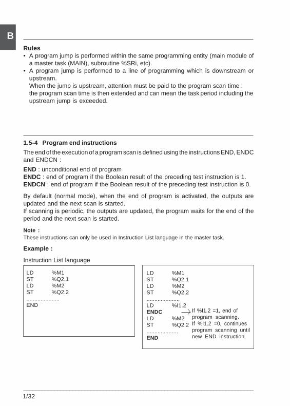
___________________________________________________________________________1/32
BRules• A program jump is performed within the same programming entity (main module of
a master task (MAIN), subroutine %SRi, etc).• A program jump is performed to a line of programming which is downstream or
upstream.When the jump is upstream, attention must be paid to the program scan time :the program scan time is then extended and can mean the task period including theupstream jump is exceeded.
1.5-4 Program end instructions
The end of the execution of a program scan is defined using the instructions END, ENDCand ENDCN :
END : unconditional end of programENDC : end of program if the Boolean result of the preceding test instruction is 1.ENDCN : end of program if the Boolean result of the preceding test instruction is 0.
By default (normal mode), when the end of program is activated, the outputs areupdated and the next scan is started.If scanning is periodic, the outputs are updated, the program waits for the end of theperiod and the next scan is started.
Note :These instructions can only be used in Instruction List language in the master task.
Example :
Instruction List language
LD %M1ST %Q2.1LD %M2ST %Q2.2.....................END
LD %M1ST %Q2.1LD %M2ST %Q2.2.....................LD %I1.2ENDCLD %M2ST %Q2.2....................END
If %I1.2 =1, end ofprogram scanning.If %I1.2 =0, continuesprogram scanning untilnew END instruction.
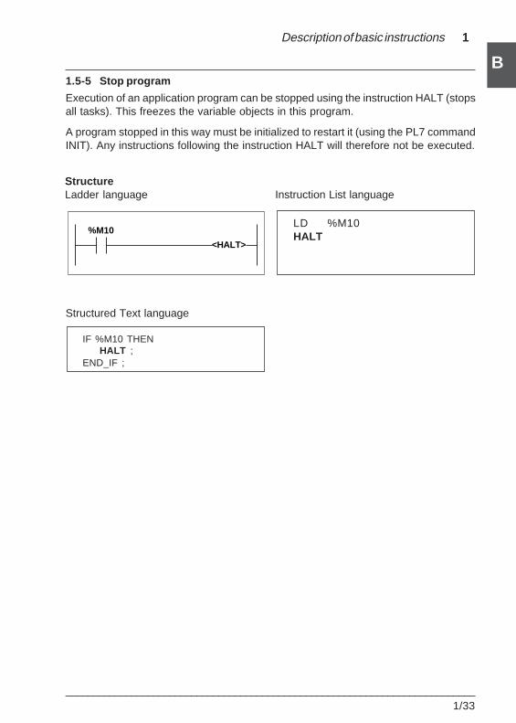
Description of basic instructions 1
___________________________________________________________________________1/33
B1.5-5 Stop program
Execution of an application program can be stopped using the instruction HALT (stopsall tasks). This freezes the variable objects in this program.
A program stopped in this way must be initialized to restart it (using the PL7 commandINIT). Any instructions following the instruction HALT will therefore not be executed.
Structured Text language
IF %M10 THENHALT ;
END_IF ;
StructureLadder language Instruction List language
LD %M10HALT
%M10
<HALT>
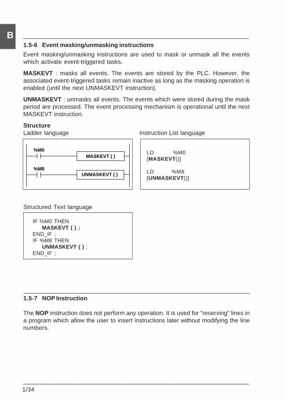
___________________________________________________________________________1/34
B1.5-6 Event masking/unmasking instructions
Event masking/unmasking instructions are used to mask or unmask all the eventswhich activate event-triggered tasks.
MASKEVT : masks all events. The events are stored by the PLC. However, theassociated event-triggered tasks remain inactive as long as the masking operation isenabled (until the next UNMASKEVT instruction).
UNMASKEVT : unmasks all events. The events which were stored during the maskperiod are processed. The event processing mechanism is operational until the nextMASKEVT instruction.
StructureLadder language Instruction List language
LD %M0[MASKEVT ()]
LD %M8[UNMASKEVT ()]
Structured Text language
IF %M0 THENMASKEVT ( ) ;
END_IF ;IF %M8 THEN
UNMASKEVT ( ) ;END_IF ;
1.5-7 NOP Instruction
The NOP instruction does not perform any operation. It is used for "reserving" lines ina program which allow the user to insert instructions later without modifying the linenumbers.
MASKEVT ( )
UNMASKEVT ( ) %M8
%M0
Description of advanced instructions 2
___________________________________________________________________________2/1
B
Section 2
2.1 Presentation of advanced instructions
2.1-1 General
The instructions described in this section are suitable for advanced programmingrequirements.
They have the same effect, irrespective of the language used. Only the syntax differs.
They are :
• Either basic instructions of the software.
• Or Functions considered as extensions of the software.
Extended Function type instructions are used to enhance the basic software usingspecial programming instructions.
• Operations on character strings, word tables, etc.
• Application-specific functions : Communication, Process control, Man-MachineInterface, etc.
They include the following families :
• Character strings.
• Word tables.
• Management of Dates, times and time periods.
• Conversions.
• Bit tables.
• "Orphee" functions.
• Communication• Process control ==> see the relevant application-specific function• Man-Machine Interface• Motion control
Notes on programming
Function type instructions require additional application memory occupation (onlywhen they are actually used in the program).This memory occupation should be taken into account by the programmer for eachfunction, irrespective of the number used, and the maximum memory size of thePLC used must be observed.
2 Description of advanced instructions
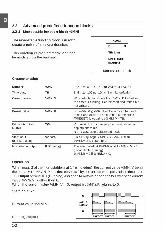
2/2___________________________________________________________________________
B2.2 Advanced predefined function blocks
2.2-1 Monostable function block %MNi
The monostable function block is used tocreate a pulse of an exact duration.
This duration is programmable and canbe modified via the terminal.
Characteristics
Number %MNi 0 to 7 for a TSX 37, 0 to 254 for a TSX 57
Time base TB 1min, 1s, 100ms, 10ms (1min by default).
Current value %MNi.V Word which decreases from %MNi.P to 0 whenthe timer is running. Can be read and tested butnot written.
Preset value %MNi.P 0 < %MNi.P < 9999. Word which can be read,tested and written. The duration of the pulse(PRESET) is equal to : %MNi.P x TB.
Edit via terminal Y/N Y : possibility of changing the preset value inMODIF adjustment mode.
N : no access in adjustment mode.
Start input S(Start) On a rising edge %MNi.V = %MNi.P then(or instruction) %MNi.V decreases to 0.
Monostable output R(Running) The associated bit %MNi.R is at 1 if %MNi.V > 0(monostable running)%MNi.R = 0 if %MNi.V = 0.
Operation
When input S of the monostable is at 1 (rising edge), the current value %MNi.V takesthe preset value %MNi.P and decreases to 0 by one unit on each pulse of the time baseTB. Output bit %MNi.R (Running) assigned to output R changes to 1 when the currentvalue %MNi.V is other than 0.When the current value %MNi.V = 0, output bit %MNi.R returns to 0.
Start input S :
Current value %MNi.V :
Running output R :
Monostable block
S
MODIF:Y
R
%MNi
TB: 1mn
MN.P:9999
PRESET PRESET PRESET
S
R
%MNi.P%MNi.V
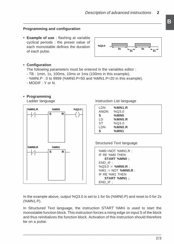
Description of advanced instructions 2
___________________________________________________________________________2/3
B
5s 5s2s 2s
%Q3.0
Programming and configuration
• Example of use : flashing at variablecyclical periods : the preset value ofeach monostable defines the durationof each pulse.
• ConfigurationThe following parameters must be entered in the variables editor :- TB : 1min, 1s, 100ms, 10ms or 1ms (100ms in this example).- %MNi.P : 0 to 9999 (%MN0.P=50 and %MN1.P=20 in this example).- MODIF : Y or N.
• ProgrammingLadder language Instruction List language
LDN %MN1.RANDN %Q3.0S %MN0LD %MN0.RST %Q3.0LDN %MN0.RS %MN1
Structured Text language
%M0:=NOT %MN1.R ;IF RE %M0 THEN
START %MN0 ;END_IF ;%Q3.0 := %MN0.R ;%M1 := NOT %MN0.R ;IF RE %M1 THEN
START %MN1 ;END_IF ;
In the example above, output %Q3.0 is set to 1 for 5s (%MN0.P) and reset to 0 for 2s(%MN1.P).
In Structured Text language, the instruction START %Mni is used to start themonostable function block. This instruction forces a rising edge on input S of the blockand thus reinitializes the function block. Activation of this instruction should thereforebe on a pulse.
%MN0
S
%Q3.0
R
%MN1.R
%MN1
S R
%MN0.R
2/4___________________________________________________________________________
BNote
The monostable function can also be performed by the function block %TMi in TPmode (see part B, section 1.3-2).
Special cases
• Effect of a cold restart : (%S0 = 1) the preset value %MNi.P is loaded into thecurrent value %MNi.V. Since the preset value which may have been modified by theterminal is lost, output %MNi.R is reset to 0.
• Effect of a warm restart : (%S1) has no effect on the current value of themonostable (%MNi.V).
• Effect of a PLC stop, de-activation of the task and break point : a PLC stop, de-activation of the current task or execution of a break point does not freeze the currentvalue.
• Effect of a program jump : the fact of not scanning the rung where the monostableblock is programmed does not freeze current value %MNi.V which continues todecrease to 0.Similarly, bit %MNi.R assigned to the monostable block output continues to operatenormally and can thus be tested in another rung.However, the coils directly "connected" to the block output (eg %Q3.0) will not beactivated since they are not scanned by the PLC.
• Testing bit %MNi.R : the state of this bit can change during a scan.
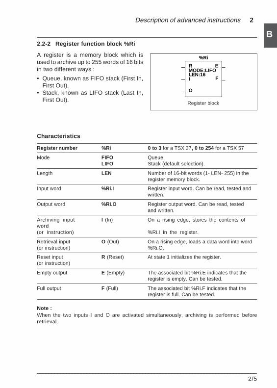
Description of advanced instructions 2
___________________________________________________________________________2/5
B
R E
%Ri
MODE:LIFOLEN:16
O
FI
2.2-2 Register function block %Ri
A register is a memory block which isused to archive up to 255 words of 16 bitsin two different ways :
• Queue, known as FIFO stack (First In,First Out).
• Stack, known as LIFO stack (Last In,First Out).
Characteristics
Register number %Ri 0 to 3 for a TSX 37, 0 to 254 for a TSX 57
Mode FIFO Queue.LIFO Stack (default selection).
Length LEN Number of 16-bit words (1- LEN- 255) in theregister memory block.
Input word %Ri.I Register input word. Can be read, tested andwritten.
Output word %Ri.O Register output word. Can be read, testedand written.
Archiving input I (In) On a rising edge, stores the contents ofword(or instruction) %Ri.I in the register.
Retrieval input O (Out) On a rising edge, loads a data word into word(or instruction) %Ri.O.
Reset input R (Reset) At state 1 initializes the register.(or instruction)
Empty output E (Empty) The associated bit %Ri.E indicates that theregister is empty. Can be tested.
Full output F (Full) The associated bit %Ri.F indicates that theregister is full. Can be tested.
Note :When the two inputs I and O are activated simultaneously, archiving is performed beforeretrieval.
Register block
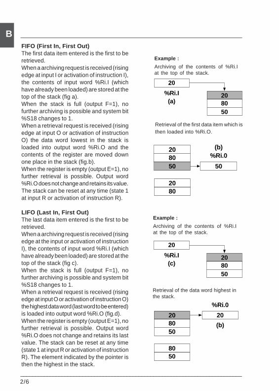
2/6___________________________________________________________________________
BFIFO (First In, First Out)The first data item entered is the first to beretrieved.When a archiving request is received (risingedge at input I or activation of instruction I),the contents of input word %Ri.I (whichhave already been loaded) are stored at thetop of the stack (fig a).When the stack is full (output F=1), nofurther archiving is possible and system bit%S18 changes to 1.When a retrieval request is received (risingedge at input O or activation of instructionO) the data word lowest in the stack isloaded into output word %Ri.O and thecontents of the register are moved downone place in the stack (fig.b).When the register is empty (output E=1), nofurther retrieval is possible. Output word%Ri.O does not change and retains its value.The stack can be reset at any time (state 1at input R or activation of instruction R).
LIFO (Last In, First Out)The last data item entered is the first to beretrieved.When a archiving request is received (risingedge at the input or activation of instructionI), the contents of input word %Ri.I (whichhave already been loaded) are stored at thetop of the stack (fig c).When the stack is full (output F=1), nofurther archiving is possible and system bit%S18 changes to 1.When a retrieval request is received (risingedge at input O or activation of instruction O)the highest data word (last word to be entered)is loaded into output word %Ri.O (fig.d).When the register is empty (output E=1), nofurther retrieval is possible. Output word%Ri.O does not change and retains its lastvalue. The stack can be reset at any time(state 1 at input R or activation of instructionR). The element indicated by the pointer isthen the highest in the stack.
Example :
Archiving of the contents of %Ri.Iat the top of the stack.
Example :
Archiving of the contents of %Ri.Iat the top of the stack.
Retrieval of the first data item which isthen loaded into %Ri.O.
Retrieval of the data word highest inthe stack.
5080
50
20
%Ri.0
(b)8020
20
8020
50
%Ri.I(c)
50
8020
50
%Ri.0(b)
8020
20
8020
50
%Ri.I(a)
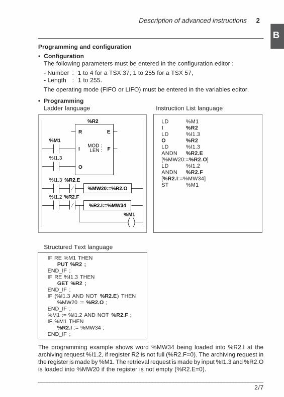
Description of advanced instructions 2
___________________________________________________________________________2/7
BProgramming and configuration
• ConfigurationThe following parameters must be entered in the configuration editor :
- Number : 1 to 4 for a TSX 37, 1 to 255 for a TSX 57,- Length : 1 to 255.
The operating mode (FIFO or LIFO) must be entered in the variables editor.
• ProgrammingLadder language Instruction List language
LD %M1I %R2LD %I1.3O %R2LD %I1.3ANDN %R2.E[%MW20:=%R2.O]LD %I1.2ANDN %R2.F[%R2.I:=%MW34]ST %M1
Structured Text language
IF RE %M1 THENPUT %R2 ;
END_IF ;IF RE %I1.3 THEN
GET %R2 ;END_IF ;IF (%I1.3 AND NOT %R2.E) THEN
%MW20 := %R2.O ;END_IF ;%M1 := %I1.2 AND NOT %R2.F ;IF %M1 THEN
%R2.I := %MW34 ;END_IF ;
The programming example shows word %MW34 being loaded into %R2.I at thearchiving request %I1.2, if register R2 is not full (%R2.F=0). The archiving request inthe register is made by %M1. The retrieval request is made by input %I1.3 and %R2.Ois loaded into %MW20 if the register is not empty (%R2.E=0).
%R2
R
O
I
%M1
%I1.3
%M1
%I1.3
%I1.2
%R2.E
%R2.F
%MW20:=%R2.O
%R2.I:=%MW34
E
FMOD :LEN :
2/8___________________________________________________________________________
B
Special cases
• Effect of a cold restart : (%S0=1) initializes the contents of the register. The Outputbit %Ri.E assigned to output E is set to 1.
• Effect of a warm restart : (%S=1) has no effect on the contents of the register, noron the state of its output bits.
• When resetting to 0 (input R or instruction R)- In Ladder language, the memorized values of inputs I and O are updated with the
actual values.- In Instruction List language, the memorized values of inputs I and O are not
updated. Each one retains the value it had before being called.- In Structured Text language, the memorized values of inputs I and O are updated
with 0.
In Structured Text language, 3 instructions are used to program the register functionblocks :
• RESET %Ri : Initializes the register,• PUT %Ri : Stores the contents of word %Ri.I in the register,• GET %Ri : Loads a data word into word %Ri.O.
The PUT and GET instructions create a rising edge on inputs I and O respectively ofthe function block. Activation of this instruction should therefore be on a pulse.
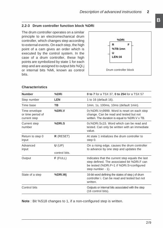
Description of advanced instructions 2
___________________________________________________________________________2/9
B2.2-3 Drum controller function block %DRi
The drum controller operates on a similarprinciple to an electromechanical drumcontroller, which changes step accordingto external events. On each step, the highpoint of a cam gives an order which isexecuted by the control system. In thecase of a drum controller, these highpoints are symbolized by state 1 for eachstep and are assigned to output bits %Qi.jor internal bits %Mi, known as controlbits.
Characteristics
Number %DRi 0 to 7 for a TSX 37, 0 to 254 for a TSX 57
Step number LEN 1 to 16 (default 16).
Time base TB 1min, 1s, 100ms, 10ms (default 1min).
Time envelope %DRi.V 0<%DRi.V<9999. Word is reset on each stepor time period of change. Can be read and tested but notcurrent step written. The duration is equal to %DRi.V x TB.
Current step %DRi.S 0<%DRi.S<15. Word which can be read andnumber tested. Can only be written with an immediate
value.
Return to step 0 R (RESET) At state 1 initializes the drum controller toinput step 0.
Advanced U (UP) On a rising edge, causes the drum controllerinput to advance by one step and updates the
control bits.
Output F (FULL) Indicates that the current step equals the laststep defined. The associated bit %DRi.F canbe tested (%DRi.F=1 if %DRi.S=configuredstep number - 1).
State of a step %DRi.Wj 16-bit word defining the states of step j of drumcontroller i. Can be read and tested but notwritten.
Control bits Outputs or internal bits associated with the step(16 control bits).
Note : Bit %S18 changes to 1, if a non-configured step is written.
Drum controller block
R F
%DRi
%TB:1mnULEN:16
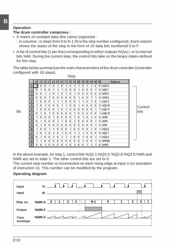
2/10___________________________________________________________________________
BOperationThe drum controller comprises :• A matrix of constant data (the cams) organized :
- in columns : in steps from 0 to N-1 (N is the step number configured). Each columnshows the states of the step in the form of 16 data bits numbered 0 to F.
• A list of control bits (1 per line) corresponding to either outputs %Qxy.i, or to internalbits %Mi. During the current step, the control bits take on the binary states definedfor this step.
The table below summarizes the main characteristics of the drum controller (controllerconfigured with 16 steps).
In the above example, for step 1, control bits %Q2.1;%Q3.5; %Q2.8;%Q3.6;%M5 and%M6 are set to state 1. The other control bits are set to 0.The current step number is incremented on each rising edge at input U (or activationof instruction U). This number can be modified by the program.
Operating diagram
Bit
Step
Controlbits
%DRi.F
U:
R:
%DRi.S 0 1 2 3 N-1 0 1 2 0 1
%DRi.V
Input
Input
Step no.
Output
Timeenvelope
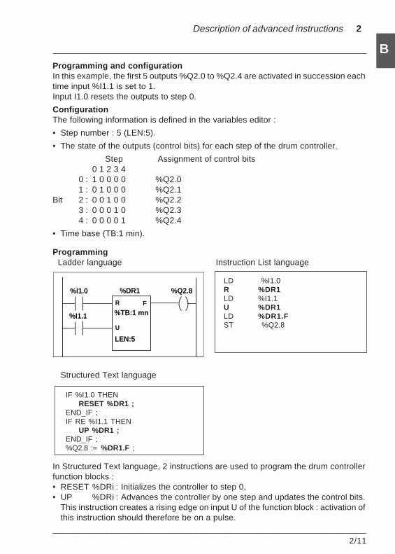
Description of advanced instructions 2
___________________________________________________________________________2/11
BProgramming and configurationIn this example, the first 5 outputs %Q2.0 to %Q2.4 are activated in succession eachtime input %I1.1 is set to 1.Input I1.0 resets the outputs to step 0.
ConfigurationThe following information is defined in the variables editor :
• Step number : 5 (LEN:5).
• The state of the outputs (control bits) for each step of the drum controller.
Step Assignment of control bits0 1 2 3 4
0 : 1 0 0 0 0 %Q2.01 : 0 1 0 0 0 %Q2.1
Bit 2 : 0 0 1 0 0 %Q2.23 : 0 0 0 1 0 %Q2.34 : 0 0 0 0 1 %Q2.4
• Time base (TB:1 min).
Programming Ladder language Instruction List language
LD %I1.0R %DR1LD %I1.1U %DR1LD %DR1.FST %Q2.8
Structured Text language
IF %I1.0 THENRESET %DR1 ;
END_IF ;IF RE %I1.1 THEN
UP %DR1 ;END_IF ;%Q2.8 := %DR1.F ;
In Structured Text language, 2 instructions are used to program the drum controllerfunction blocks :• RESET %DRi : Initializes the controller to step 0,• UP %DRi : Advances the controller by one step and updates the control bits.
This instruction creates a rising edge on input U of the function block : activation ofthis instruction should therefore be on a pulse.
%DR1
R F
U
LEN:5
%TB:1 mn%I1.1
%Q2.8%I1.0
2/12___________________________________________________________________________
BNote
When resetting to 0 (input R, instruction R or RESET instruction)• In Ladder language, the memorized value of input U is updated with the actual
values.• In Instruction List language, the memorized value of input U is not updated. It
retains the value it had before being called.• In Structured Text language, the memorized value of input U is updated with 0.
Special cases• Effect of a cold restart : (%S0=1) resets the drum controller to step 0 (with updating
of the control bits).• Effect of a warm restart : (%S1=1) updates the control bits, according to the current
step.• Effect of a program jump, de-activation of the task and break point : the fact of
not scanning the drum controller means that the control bits are not reset to 0.• Updating the control bits : only occurs when there is a change of step or in the case
of a cold or warm restart.
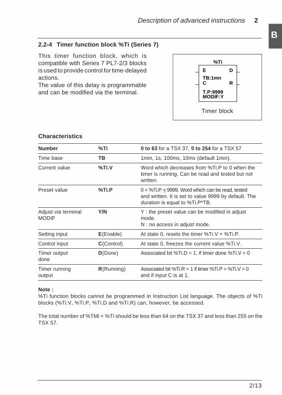
Description of advanced instructions 2
___________________________________________________________________________2/13
B2.2-4 Timer function block %Ti (Series 7)
This timer function block, which iscompatible with Series 7 PL7-2/3 blocksis used to provide control for time-delayedactions.The value of this delay is programmableand can be modified via the terminal.
Characteristics
Number %Ti 0 to 63 for a TSX 37, 0 to 254 for a TSX 57
Time base TB 1min, 1s, 100ms, 10ms (default 1min).
Current value %Ti.V Word which decreases from %Ti.P to 0 when thetimer is running. Can be read and tested but notwritten.
Preset value %Ti.P 0 < %Ti.P < 9999. Word which can be read, testedand written. It is set to value 9999 by default. Theduration is equal to %Ti.P*TB.
Adjust via terminal Y/N Y : the preset value can be modified in adjustMODIF mode.
N : no access in adjust mode.
Setting input E(Enable) At state 0, resets the timer %Ti.V = %Ti.P.
Control input C(Control) At state 0, freezes the current value %Ti.V.
Timer output D(Done) Associated bit %Ti.D = 1, if timer done %Ti.V = 0done
Timer running R(Running) Associated bit %Ti.R = 1 if timer %Ti.P > %Ti.V > 0output and if input C is at 1.
Note :%Ti function blocks cannot be programmed in Instruction List language. The objects of %Tiblocks (%Ti.V, %Ti.P, %Ti.D and %Ti.R) can, however, be accessed.
The total number of %TMi + %Ti should be less than 64 on the TSX 37 and less than 255 on theTSX 57.
Timer block
E D
%Ti
TB:1mnRC
T.P:9999MODIF:Y
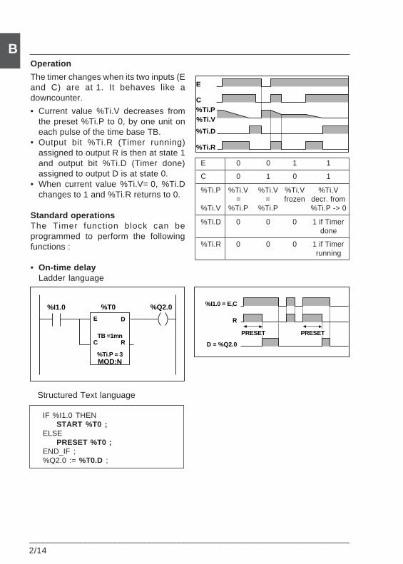
2/14___________________________________________________________________________
BOperation
The timer changes when its two inputs (Eand C) are at 1. It behaves like adowncounter.
• Current value %Ti.V decreases fromthe preset %Ti.P to 0, by one unit oneach pulse of the time base TB.
• Output bit %Ti.R (Timer running)assigned to output R is then at state 1and output bit %Ti.D (Timer done)assigned to output D is at state 0.
• When current value %Ti.V= 0, %Ti.Dchanges to 1 and %Ti.R returns to 0.
Standard operationsThe Timer function block can beprogrammed to perform the followingfunctions :
• On-time delayLadder language
E 0 0 1 1
C 0 1 0 1
%Ti.P %Ti.V %Ti.V %Ti.V %Ti.V= = frozen decr. from
%Ti.V %Ti.P %Ti.P %Ti.P -> 0
%Ti.D 0 0 0 1 if Timerdone
%Ti.R 0 0 0 1 if Timerrunning
Structured Text language
IF %I1.0 THENSTART %T0 ;
ELSEPRESET %T0 ;
END_IF ;%Q2.0 := %T0.D ;
%T0
E D
C
MOD:N
%Q2.0%I1.0
%Ti.P = 3
RTB =1mn
%I1.0 = E,C
R
PRESETPRESET
D = %Q2.0
E
C
%Ti.V
%Ti.D
%Ti.R
%Ti.P
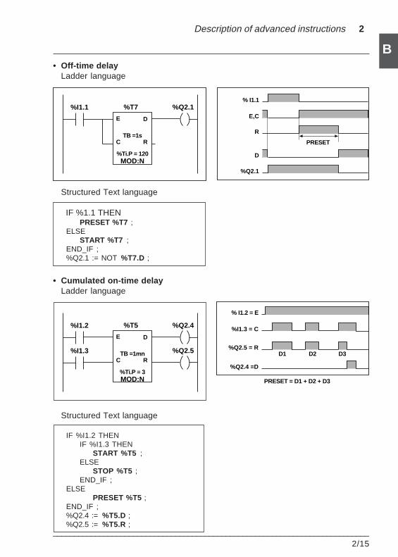
Description of advanced instructions 2
___________________________________________________________________________2/15
B• Off-time delay
Ladder language
Structured Text language
IF %1.1 THENPRESET %T7 ;
ELSESTART %T7 ;
END_IF ;%Q2.1 := NOT %T7.D ;
• Cumulated on-time delayLadder language
Structured Text language
IF %I1.2 THENIF %I1.3 THEN
START %T5 ;ELSE
STOP %T5 ;END_IF ;
ELSEPRESET %T5 ;
END_IF ;%Q2.4 := %T5.D ;%Q2.5 := %T5.R ;
%T5
E D
C
MOD:N
%Q2.4%I1.2
%Ti.P = 3
RTB =1mn %Q2.5%I1.3
% I1.1
E,C
R
PRESET
D
%Q2.1
%T7
E D
C
MOD:N
%Q2.1%I1.1
%Ti.P = 120
RTB =1s
% I1.2 = E
%Q2.4 =D
%I1.3 = C
%Q2.5 = RD1 D2 D3
PRESET = D1 + D2 + D3
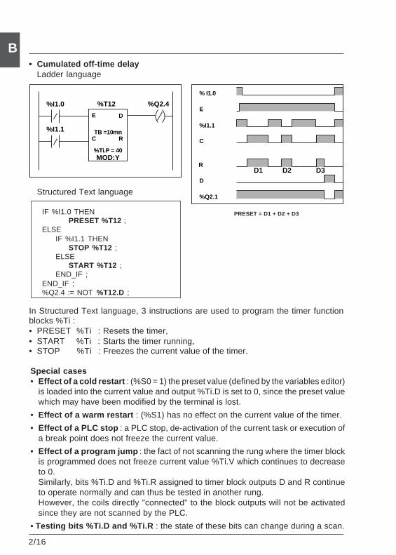
2/16___________________________________________________________________________
B• Cumulated off-time delay
Ladder language
Structured Text language
IF %I1.0 THENPRESET %T12 ;
ELSEIF %I1.1 THEN
STOP %T12 ;ELSE
START %T12 ;END_IF ;
END_IF ;%Q2.4 := NOT %T12.D ;
In Structured Text language, 3 instructions are used to program the timer functionblocks %Ti :• PRESET %Ti : Resets the timer,• START %Ti : Starts the timer running,• STOP %Ti : Freezes the current value of the timer.
Special cases• Effect of a cold restart : (%S0 = 1) the preset value (defined by the variables editor)
is loaded into the current value and output %Ti.D is set to 0, since the preset valuewhich may have been modified by the terminal is lost.
• Effect of a warm restart : (%S1) has no effect on the current value of the timer.
• Effect of a PLC stop : a PLC stop, de-activation of the current task or execution ofa break point does not freeze the current value.
• Effect of a program jump : the fact of not scanning the rung where the timer blockis programmed does not freeze current value %Ti.V which continues to decreaseto 0.Similarly, bits %Ti.D and %Ti.R assigned to timer block outputs D and R continueto operate normally and can thus be tested in another rung.However, the coils directly "connected" to the block outputs will not be activatedsince they are not scanned by the PLC.
• Testing bits %Ti.D and %Ti.R : the state of these bits can change during a scan.
PRESET = D1 + D2 + D3
E
%I1.1
C
R
D
% I1.0
%Q2.1
D1 D2 D3
%T12
E D
C
MOD:Y
%Q2.4%I1.0
%Ti.P = 40
RTB =10mn%I1.1
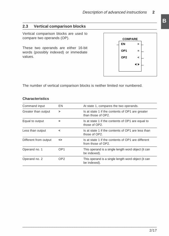
Description of advanced instructions 2
___________________________________________________________________________2/17
B
EN
OP1
OP2
>
COMPARE
=
<
< >< >
2.3 Vertical comparison blocks
Vertical comparison blocks are used tocompare two operands (OP).
These two operands are either 16-bitwords (possibly indexed) or immediatevalues.
The number of vertical comparison blocks is neither limited nor numbered.
Characteristics
Command input EN At state 1, compares the two operands.
Greater than output > Is at state 1 if the contents of OP1 are greaterthan those of OP2.
Equal to output = Is at state 1 if the contents of OP1 are equal tothose of OP2.
Less than output < Is at state 1 if the contents of OP1 are less thanthose of OP2.
Different from output <> Is at state 1 if the contents of OP1 are differentfrom those of OP2.
Operand no. 1 OP1 This operand is a single length word object (it canbe indexed).
Operand no. 2 OP2 This operand is a single length word object (it canbe indexed).
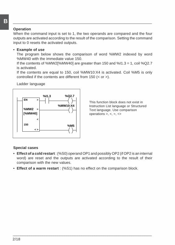
2/18___________________________________________________________________________
BOperationWhen the command input is set to 1, the two operands are compared and the fouroutputs are activated according to the result of the comparison. Setting the commandinput to 0 resets the activated outputs.
• Example of useThe program below shows the comparison of word %MW2 indexed by word%MW40 with the immediate value 150.If the contents of %MW2[%MW40] are greater than 150 and %I1.3 = 1, coil %Q2.7is activated.If the contents are equal to 150, coil %MW10:X4 is activated. Coil %M5 is onlycontrolled if the contents are different from 150 (< or >).
Ladder language
This function block does not exist inInstruction List language or StructuredText language. Use comparisonoperations >, <, =, <>
Special cases
• Effect of a cold restart : (%S0) operand OP1 and possibly OP2 (if OP2 is an internalword) are reset and the outputs are activated according to the result of theircomparison with the new values.
• Effect of a warm restart : (%S1) has no effect on the comparison block.
=
%Q2.7
<
%I1.3>
< >
EN
%MW10:X4
%M5
%MW2[%MW40]
150
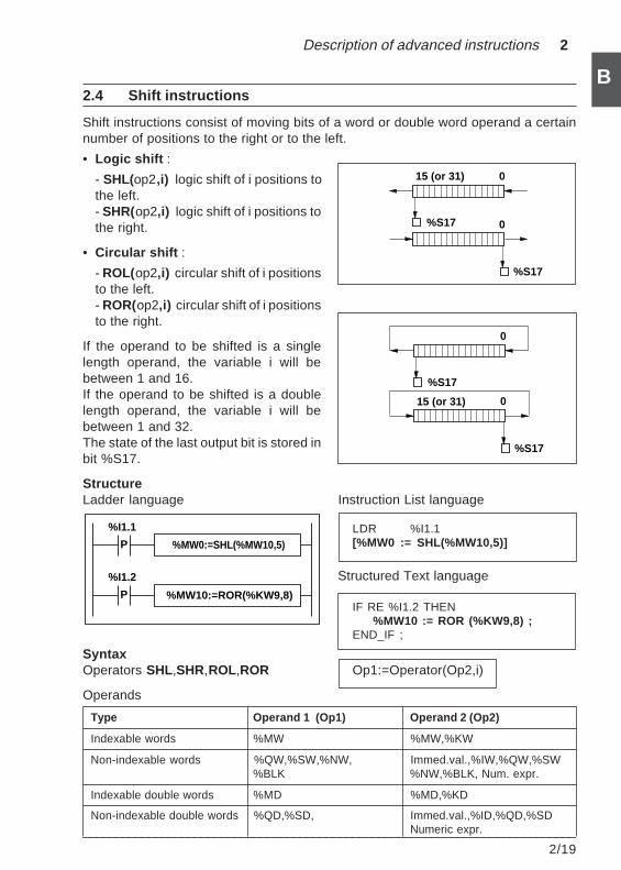
Description of advanced instructions 2
___________________________________________________________________________2/19
B2.4 Shift instructions
Shift instructions consist of moving bits of a word or double word operand a certainnumber of positions to the right or to the left.
• Logic shift :
- SHL(op2,i) logic shift of i positions tothe left.- SHR(op2,i) logic shift of i positions tothe right.
• Circular shift :
- ROL(op2,i) circular shift of i positionsto the left.- ROR(op2,i) circular shift of i positionsto the right.
If the operand to be shifted is a singlelength operand, the variable i will bebetween 1 and 16.If the operand to be shifted is a doublelength operand, the variable i will bebetween 1 and 32.The state of the last output bit is stored inbit %S17.
StructureLadder language Instruction List language
LDR %I1.1[%MW0 := SHL(%MW10,5)]
Structured Text language
IF RE %I1.2 THEN%MW10 := ROR (%KW9,8) ;
END_IF ;
SyntaxOperators SHL,SHR,ROL,ROR Op1:=Operator(Op2,i)
Operands
Type Operand 1 (Op1) Operand 2 (Op2)
Indexable words %MW %MW,%KW
Non-indexable words %QW,%SW,%NW, Immed.val.,%IW,%QW,%SW%BLK %NW,%BLK, Num. expr.
Indexable double words %MD %MD,%KD
Non-indexable double words %QD,%SD, Immed.val.,%ID,%QD,%SDNumeric expr.
15 (or 31) 0
0%S17
%S17
0
0
%S17
%S17
15 (or 31)
%MW0:=SHL(%MW10,5)
%MW10:=ROR(%KW9,8)
%I1.2
P
%I1.1
P
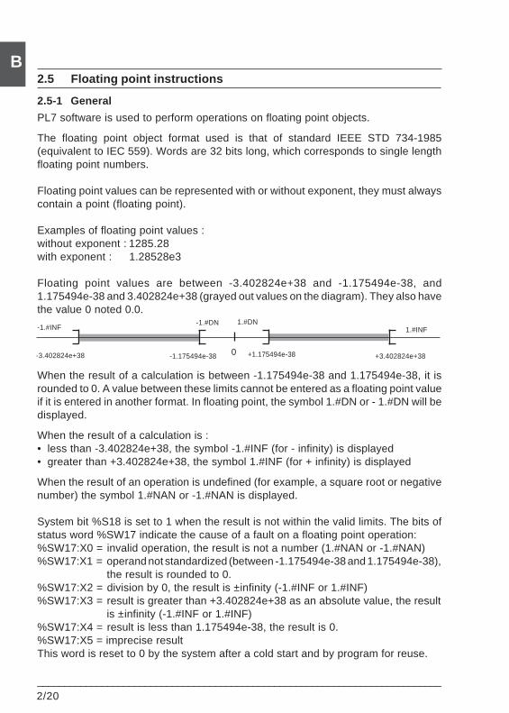
2/20___________________________________________________________________________
B2.5 Floating point instructions
2.5-1 General
PL7 software is used to perform operations on floating point objects.
The floating point object format used is that of standard IEEE STD 734-1985(equivalent to IEC 559). Words are 32 bits long, which corresponds to single lengthfloating point numbers.
Floating point values can be represented with or without exponent, they must alwayscontain a point (floating point).
Examples of floating point values :without exponent : 1285.28with exponent : 1.28528e3
Floating point values are between -3.402824e+38 and -1.175494e-38, and1.175494e-38 and 3.402824e+38 (grayed out values on the diagram). They also havethe value 0 noted 0.0.
When the result of a calculation is between -1.175494e-38 and 1.175494e-38, it isrounded to 0. A value between these limits cannot be entered as a floating point valueif it is entered in another format. In floating point, the symbol 1.#DN or - 1.#DN will bedisplayed.
When the result of a calculation is :• less than -3.402824e+38, the symbol -1.#INF (for - infinity) is displayed• greater than +3.402824e+38, the symbol 1.#INF (for + infinity) is displayed
When the result of an operation is undefined (for example, a square root or negativenumber) the symbol 1.#NAN or -1.#NAN is displayed.
System bit %S18 is set to 1 when the result is not within the valid limits. The bits ofstatus word %SW17 indicate the cause of a fault on a floating point operation:%SW17:X0 = invalid operation, the result is not a number (1.#NAN or -1.#NAN)%SW17:X1 = operand not standardized (between -1.175494e-38 and 1.175494e-38),
the result is rounded to 0.%SW17:X2 = division by 0, the result is ±infinity (-1.#INF or 1.#INF)%SW17:X3 = result is greater than +3.402824e+38 as an absolute value, the result
is ±infinity (-1.#INF or 1.#INF)%SW17:X4 = result is less than 1.175494e-38, the result is 0.%SW17:X5 = imprecise resultThis word is reset to 0 by the system after a cold start and by program for reuse.
0-3.402824e+38 -1.175494e-38 +1.175494e-38 +3.402824e+38
1.#INF-1.#INF-1.#DN 1.#DN
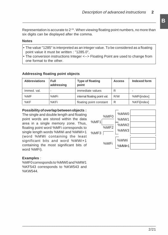
Description of advanced instructions 2
___________________________________________________________________________2/21
B
Representation is accurate to 2-24. When viewing floating point numbers, no more thansix digits can be displayed after the comma.
Notes
• The value "1285" is interpreted as an integer value. To be considered as a floatingpoint value it must be written : "1285.0",
• The conversion instructions Integer <--> Floating Point are used to change fromone format to the other.
Addressing floating point objects
Abbreviations Full Type of floating Access Indexed formaddressing point
Immed. val. - immediate values R -
%MF %MFi internal floating point val. R/W %MFi[index]
%KF %KFi floating point constant R %KFi[index]
Possibility of overlap between objects :The single and double length and floatingpoint words are stored within the dataarea in a single memory zone. Thus,floating point word %MFi corresponds tosingle length words %MWi and %MWi+1(word %MWi containing the leastsignificant bits and word %MWi+1containing the most significant bits ofword %MFi).
Examples :%MF0 corresponds to %MW0 and %MW1%KF543 corresponds to %KW543 and%KW544.
%MW0
%MW1
%MW2
%MW3
%MWi
%MWi+1
%MF0
%MF2
%MFi
%MF1
%MF3
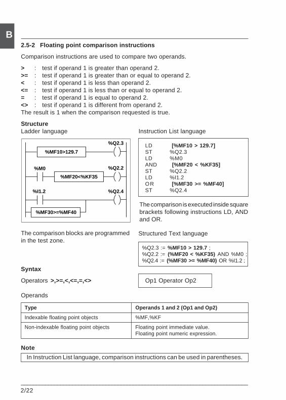
2/22___________________________________________________________________________
B2.5-2 Floating point comparison instructions
Comparison instructions are used to compare two operands.
> : test if operand 1 is greater than operand 2.>= : test if operand 1 is greater than or equal to operand 2.< : test if operand 1 is less than operand 2.<= : test if operand 1 is less than or equal to operand 2.= : test if operand 1 is equal to operand 2.<> : test if operand 1 is different from operand 2.The result is 1 when the comparison requested is true.
StructureLadder language Instruction List language
LD [%MF10 > 129.7]ST %Q2.3LD %M0AND [%MF20 < %KF35]ST %Q2.2LD %I1.2OR [%MF30 >= %MF40]ST %Q2.4
The comparison is executed inside squarebrackets following instructions LD, ANDand OR.
The comparison blocks are programmedin the test zone.
Syntax
Operators >,>=,<,<=,=,<> Op1 Operator Op2
Operands
Type Operands 1 and 2 (Op1 and Op2)
Indexable floating point objects %MF,%KF
Non-indexable floating point objects Floating point immediate value.Floating point numeric expression.
Note
In Instruction List language, comparison instructions can be used in parentheses.
Structured Text language
%Q2.3 := %MF10 > 129.7 ;%Q2.2 := (%MF20 < %KF35) AND %M0 ;%Q2.4 := (%MF30 >= %MF40) OR %I1.2 ;
%M0
%I1.2
%MF10>129.7
%MF20<%KF35
%MF30>=%MF40
%Q2.3
%Q2.2
%Q2.4
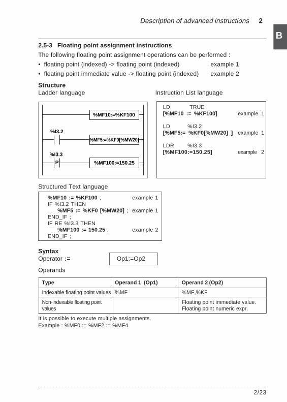
Description of advanced instructions 2
___________________________________________________________________________2/23
B2.5-3 Floating point assignment instructions
The following floating point assignment operations can be performed :
• floating point (indexed) -> floating point (indexed) example 1
• floating point immediate value -> floating point (indexed) example 2
StructureLadder language Instruction List language
LD TRUE[%MF10 := %KF100] example 1
LD %I3.2[%MF5:= %KF0[%MW20] ] example 1
LDR %I3.3[%MF100:=150.25] example 2
Structured Text language
%MF10 := %KF100 ; example 1IF %I3.2 THEN
%MF5 := %KF0 [%MW20] ; example 1END_IF ;IF RE %I3.3 THEN
%MF100 := 150.25 ; example 2END_IF ;
SyntaxOperator := Op1:=Op2
Operands
Type Operand 1 (Op1) Operand 2 (Op2)
Indexable floating point values %MF %MF,%KF
Non-indexable floating point Floating point immediate value.values Floating point numeric expr.
It is possible to execute multiple assignments.Example : %MF0 := %MF2 := %MF4
%I3.2
%I3.3
%MF10:=%KF100
%MF5:=%KF0[%MW20]
%MF100:=150.25P
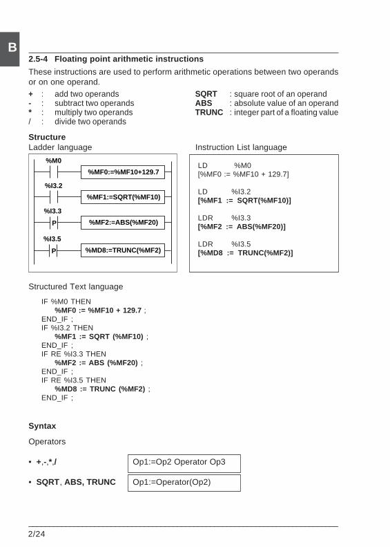
2/24___________________________________________________________________________
B2.5-4 Floating point arithmetic instructions
These instructions are used to perform arithmetic operations between two operandsor on one operand.+ : add two operands SQRT : square root of an operand- : subtract two operands ABS : absolute value of an operand* : multiply two operands TRUNC : integer part of a floating value/ : divide two operands
StructureLadder language Instruction List language
LD %M0[%MF0 := %MF10 + 129.7]
LD %I3.2[%MF1 := SQRT(%MF10)]
LDR %I3.3[%MF2 := ABS(%MF20)]
LDR %I3.5[%MD8 := TRUNC(%MF2)]
Structured Text language
IF %M0 THEN%MF0 := %MF10 + 129.7 ;
END_IF ;IF %I3.2 THEN
%MF1 := SQRT (%MF10) ;END_IF ;IF RE %I3.3 THEN
%MF2 := ABS (%MF20) ;END_IF ;IF RE %I3.5 THEN
%MD8 := TRUNC (%MF2) ;END_IF ;
Syntax
Operators
• +,-,*,/ Op1:=Op2 Operator Op3
• SQRT, ABS, TRUNC Op1:=Operator(Op2)
P
%I3.2
%I3.3
%MF0:=%MF10+129.7
%MF1:=SQRT(%MF10)
%M0
P %MF2:=ABS(%MF20)
%I3.5
P %MD8:=TRUNC(%MF2)
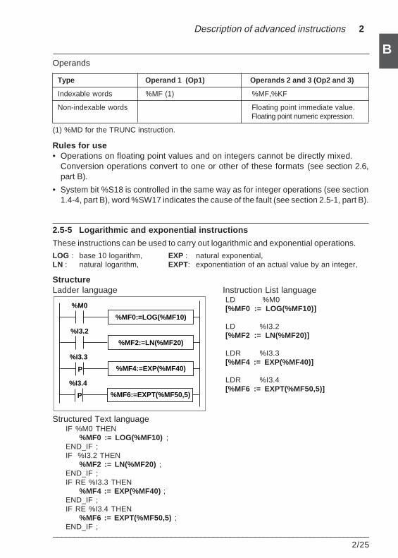
Description of advanced instructions 2
___________________________________________________________________________2/25
BOperands
Type Operand 1 (Op1) Operands 2 and 3 (Op2 and 3)
Indexable words %MF (1) %MF,%KF
Non-indexable words Floating point immediate value.Floating point numeric expression.
(1) %MD for the TRUNC instruction.
Rules for use• Operations on floating point values and on integers cannot be directly mixed.
Conversion operations convert to one or other of these formats (see section 2.6,part B).
• System bit %S18 is controlled in the same way as for integer operations (see section1.4-4, part B), word %SW17 indicates the cause of the fault (see section 2.5-1, part B).
2.5-5 Logarithmic and exponential instructions
These instructions can be used to carry out logarithmic and exponential operations.LOG : base 10 logarithm, EXP : natural exponential,LN : natural logarithm, EXPT: exponentiation of an actual value by an integer,
StructureLadder language Instruction List language
LD %M0[%MF0 := LOG(%MF10)]
LD %I3.2[%MF2 := LN(%MF20)]
LDR %I3.3[%MF4 := EXP(%MF40)]
LDR %I3.4[%MF6 := EXPT(%MF50,5)]
Structured Text languageIF %M0 THEN
%MF0 := LOG(%MF10) ;END_IF ;IF %I3.2 THEN
%MF2 := LN(%MF20) ;END_IF ;IF RE %I3.3 THEN
%MF4 := EXP(%MF40) ;END_IF ;IF RE %I3.4 THEN
%MF6 := EXPT(%MF50,5) ;END_IF ;
%I3.2
%I3.3
%MF0:=LOG(%MF10)
%MF2:=LN(%MF20)
%M0
P %MF4:=EXP(%MF40)
%I3.4
P %MF6:=EXPT(%MF50,5)
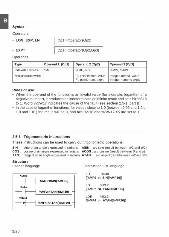
2/26___________________________________________________________________________
B
%I3.2
%I3.3
%MF0:=SIN(%MF10)
%MF2:=TAN(%MF10)
%M0
P %MF4:=ATAN(%MF20)
Syntax
Operators
• LOG, EXP, LN Op1:=Operator(Op2)
• EXPT Op1:=Operator(Op2,Op3)
Operands
Type Operand 1 (Op1) Operand 2 (Op2) Operand 3 (Op3)
Indexable words %MF %MF,%KF %MW, %KW
Non-indexable words Fl. point immed. value Integer immed. valueFl. point. num. expr. Integer numeric expr.
Rules of use• When the operand of the function is an invalid value (for example, logarithm of a
negative number), it produces an indeterminate or infinite result and sets bit %S18to 1. Word %SW17 indicates the cause of the fault (see section 2.5-1, part B).
• In the case of logarithm functions, for values close to 1.0 (between 0.99 and 1.0 or1.0 and 1.01) the result will be 0, and bits %S18 and %SW17:X5 are set to 1.
2.5-6 Trigonometric instructions
These instructions can be used to carry out trigonometric operations.SIN : sine of an angle expressed in radians ASIN : arc sine (result between -π/2 and π/2)COS : cosine of an angle expressed in radians ACOS : arc cosine (result between 0 and π)TAN : tangent of an angle expressed in radians ATAN : arc tangent (result between -π/2 and π/2)
StructureLadder language Instruction List language
LD %M0[%MF0 := SIN(%MF10)]
LD %I3.2[%MF2 := TAN(%MF10)]
LDR %I3.3[%MF4 := ATAN(%MF20)]
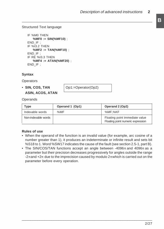
Description of advanced instructions 2
___________________________________________________________________________2/27
BStructured Text language
IF %M0 THEN%MF0 := SIN(%MF10) ;
END_IF ;IF %I3.2 THEN
%MF2 := TAN(%MF10) ;END_IF ;IF RE %I3.3 THEN
%MF4 := ATAN(%MF20) ;END_IF ;
Syntax
Operators
• SIN, COS, TAN Op1:=Operator(Op2)
ASIN, ACOS, ATAN
Operands
Type Operand 1 (Op1) Operand 2 (Op2)
Indexable words %MF %MF,%KF
Non-indexable words Floating point immediate valueFloating point numeric expression
Rules of use• When the operand of the function is an invalid value (for example, arc cosine of a
number greater than 1), it produces an indeterminate or infinite result and sets bit%S18 to 1. Word %SW17 indicates the cause of the fault (see section 2.5-1, part B).
• The SIN/COS/TAN functions accept an angle between -4096π and 4096π as aparameter but their precision decreases progressively for angles outside the range-2π and +2π due to the imprecision caused by modulo 2π which is carried out on theparameter before every operation.
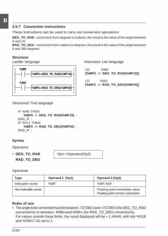
2/28___________________________________________________________________________
B2.5-7 Conversion instructions
These instructions can be used to carry out conversion operations:DEG_TO_RAD : conversion from degrees to radians, the result is the value of the angle between0 and 2πRAD_TO_DEG : conversion from radians to degrees, the result is the value of the angle between0 and 360 degrees
StructureLadder language Instruction List language
LD %M0[%MF0 := DEG_TO_RAD(%MF10)]
LD %M2[%MF2 := RAD_TO_DEG(%MF20)]
Structured Text language
IF %M0 THEN%MF0 := DEG_TO_RAD(%MF10) ;
END_IF ;IF %I3.2 THEN
%MF2 := RAD_TO_DEG(%MF20) ;END_IF ;
Syntax
Operators
• DEG_TO_RAD Op1:=Operator(Op2)
RAD_TO_DEG
Operands
Type Operand 1 (Op1) Operand 2 (Op2)
Indexable words %MF %MF,%KF
Non-indexable words Floating point immediate valueFloating point numeric expression
Rules of use• The angle to be converted must be between -737280.0 and +737280.0 (for DEG_TO_RAD
conversions) or between -4096π and 4096π (for RAD_TO_DEG conversions).For values outside these limits, the result displayed will be + 1.#NAN, with bits %S18and %SW17:X0 set to 1.
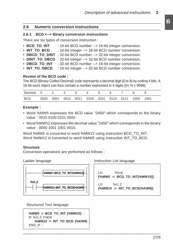
Description of advanced instructions 2
___________________________________________________________________________2/29
B2.6 Numeric conversion instructions
2.6-1 BCD <--> Binary conversion instructions
There are six types of conversion instruction :
• BCD_TO_INT : 16-bit BCD number --> 16-bit integer conversion.• INT_TO_BCD : 16-bit integer --> 16-bit BCD number conversion.• DBCD_TO_DINT : 32-bit BCD number --> 32-bit integer conversion.• DINT_TO_DBCD : 32-bit integer --> 32-bit BCD number conversion.• DBCD_TO_INT : 32-bit BCD number --> 16-bit integer conversion.• INT_TO_DBCD : 16-bit integer --> 32-bit BCD number conversion.
Review of the BCD code :The BCD (Binary Coded Decimal) code represents a decimal digit (0 to 9) by coding 4 bits. A16-bit word object can thus contain a number expressed in 4 digits (0< N < 9999).
Decimal 0 1 2 3 4 5 6 7 8 9
BCD 0000 0001 0010 0011 0100 0101 0110 0111 1000 1001
Example :
• Word %MW5 expresses the BCD value "2450" which corresponds to the binaryvalue : 0010 0100 0101 0000.
• Word %MW12 expresses the decimal value "2450" which corresponds to the binaryvalue : 0000 1001 1001 0010.
Word %MW5 is converted to word %MW12 using instruction BCD_TO_INT.Word %MW12 is converted to word %MW5 using instruction INT_TO_BCD.
StructureConversion operations are performed as follows :
Ladder language Instruction List language
LD TRUE[%MW0 := BCD_TO_INT(%MW10)]
LD %I1.2[%MW10 := INT_TO_BCD(%KW9)]
Structured Text language
%MW0 := BCD_TO_INT (%MW10) ;IF %I1.2 THEN
%MW10 := INT_TO_BCD (%KW9) ;END_IF ;
%MW0:=BCD_TO_INT(%MW10)
%MW10:=INT_TO_BCD(%KW9)
%I1.2
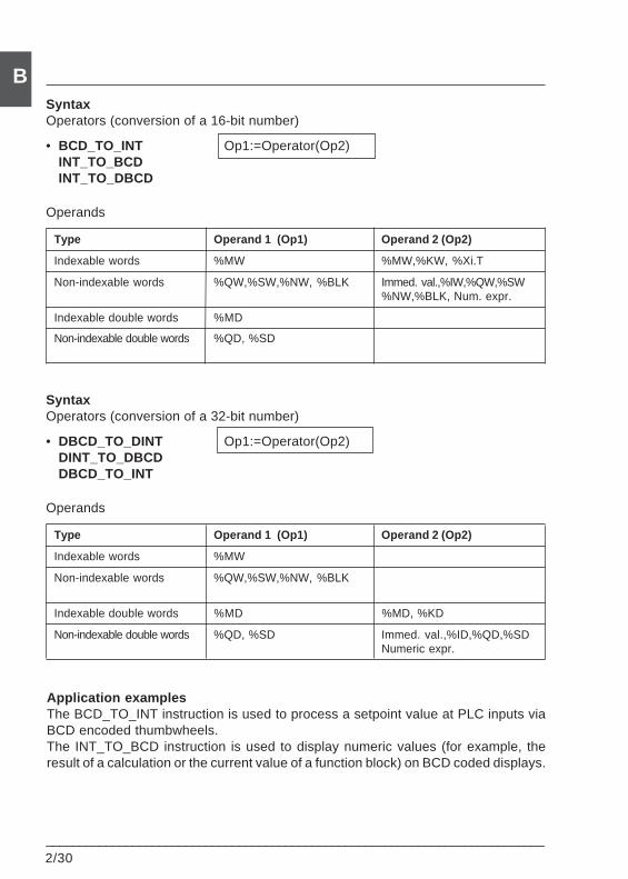
2/30___________________________________________________________________________
B
Application examplesThe BCD_TO_INT instruction is used to process a setpoint value at PLC inputs viaBCD encoded thumbwheels.The INT_TO_BCD instruction is used to display numeric values (for example, theresult of a calculation or the current value of a function block) on BCD coded displays.
SyntaxOperators (conversion of a 16-bit number)
• BCD_TO_INT Op1:=Operator(Op2)INT_TO_BCDINT_TO_DBCD
Operands
Type Operand 1 (Op1) Operand 2 (Op2)
Indexable words %MW %MW,%KW, %Xi.T
Non-indexable words %QW,%SW,%NW, %BLK Immed. val.,%IW,%QW,%SW%NW,%BLK, Num. expr.
Indexable double words %MD
Non-indexable double words %QD, %SD
SyntaxOperators (conversion of a 32-bit number)
• DBCD_TO_DINT Op1:=Operator(Op2)DINT_TO_DBCDDBCD_TO_INT
Operands
Type Operand 1 (Op1) Operand 2 (Op2)
Indexable words %MW
Non-indexable words %QW,%SW,%NW, %BLK
Indexable double words %MD %MD, %KD
Non-indexable double words %QD, %SD Immed. val.,%ID,%QD,%SDNumeric expr.
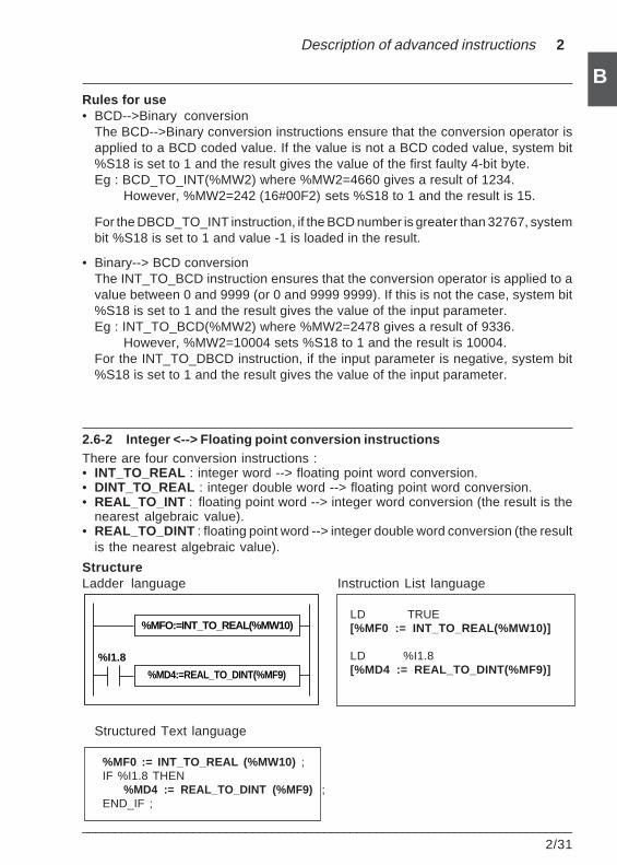
Description of advanced instructions 2
___________________________________________________________________________2/31
BRules for use• BCD-->Binary conversion
The BCD-->Binary conversion instructions ensure that the conversion operator isapplied to a BCD coded value. If the value is not a BCD coded value, system bit%S18 is set to 1 and the result gives the value of the first faulty 4-bit byte.Eg : BCD_TO_INT(%MW2) where %MW2=4660 gives a result of 1234.
However, %MW2=242 (16#00F2) sets %S18 to 1 and the result is 15.
For the DBCD_TO_INT instruction, if the BCD number is greater than 32767, systembit %S18 is set to 1 and value -1 is loaded in the result.
• Binary--> BCD conversionThe INT_TO_BCD instruction ensures that the conversion operator is applied to avalue between 0 and 9999 (or 0 and 9999 9999). If this is not the case, system bit%S18 is set to 1 and the result gives the value of the input parameter.Eg : INT_TO_BCD(%MW2) where %MW2=2478 gives a result of 9336.
However, %MW2=10004 sets %S18 to 1 and the result is 10004.For the INT_TO_DBCD instruction, if the input parameter is negative, system bit%S18 is set to 1 and the result gives the value of the input parameter.
2.6-2 Integer <--> Floating point conversion instructionsThere are four conversion instructions :• INT_TO_REAL : integer word --> floating point word conversion.• DINT_TO_REAL : integer double word --> floating point word conversion.• REAL_TO_INT : floating point word --> integer word conversion (the result is the
nearest algebraic value).• REAL_TO_DINT : floating point word --> integer double word conversion (the result
is the nearest algebraic value).
StructureLadder language Instruction List language
LD TRUE[%MF0 := INT_TO_REAL(%MW10)]
LD %I1.8[%MD4 := REAL_TO_DINT(%MF9)]
Structured Text language
%MF0 := INT_TO_REAL (%MW10) ;IF %I1.8 THEN
%MD4 := REAL_TO_DINT (%MF9) ;END_IF ;
%MD4:=REAL_TO_DINT(%MF9)
%MFO:=INT_TO_REAL(%MW10)
%I1.8
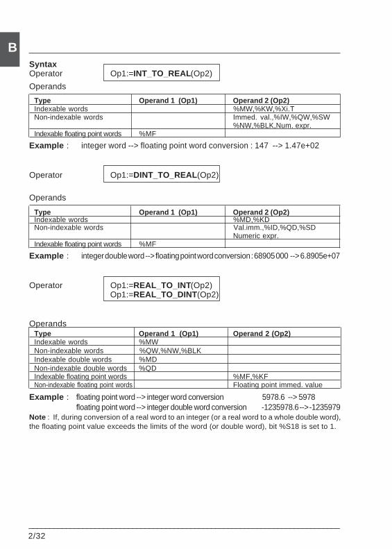
2/32___________________________________________________________________________
BSyntaxOperator Op1:=INT_TO_REAL(Op2)
Operands
Type Operand 1 (Op1) Operand 2 (Op2)Indexable words %MW,%KW,%Xi.TNon-indexable words Immed. val.,%IW,%QW,%SW
%NW,%BLK,Num. expr.Indexable floating point words %MF
Example : integer word --> floating point word conversion : 147 --> 1.47e+02
Operator Op1:=DINT_TO_REAL (Op2)
Operands
Type Operand 1 (Op1) Operand 2 (Op2)Indexable words %MD,%KDNon-indexable words Val.imm.,%ID,%QD,%SD
Numeric expr.Indexable floating point words %MF
Example : integer double word --> floating point word conversion : 68905 000 --> 6.8905e+07
Operator Op1:=REAL_TO_INT(Op2) Op1:=REAL_TO_DINT (Op2)
OperandsType Operand 1 (Op1) Operand 2 (Op2)Indexable words %MWNon-indexable words %QW,%NW,%BLKIndexable double words %MDNon-indexable double words %QDIndexable floating point words %MF,%KFNon-indexable floating point words Floating point immed. value
Example : floating point word --> integer word conversion 5978.6 --> 5978floating point word --> integer double word conversion -1235978.6 --> -1235979
Note : If, during conversion of a real word to an integer (or a real word to a whole double word),the floating point value exceeds the limits of the word (or double word), bit %S18 is set to 1.
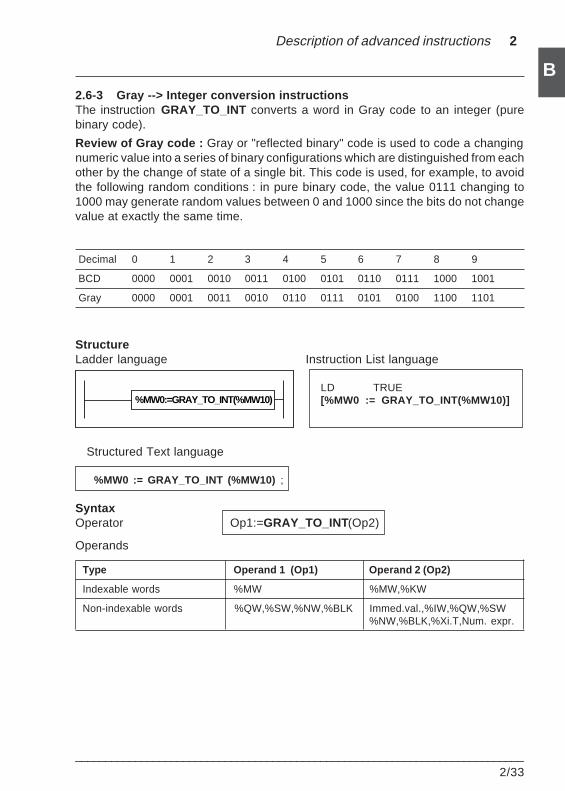
Description of advanced instructions 2
___________________________________________________________________________2/33
B2.6-3 Gray --> Integer conversion instructionsThe instruction GRAY_TO_INT converts a word in Gray code to an integer (purebinary code).
Review of Gray code : Gray or "reflected binary" code is used to code a changingnumeric value into a series of binary configurations which are distinguished from eachother by the change of state of a single bit. This code is used, for example, to avoidthe following random conditions : in pure binary code, the value 0111 changing to1000 may generate random values between 0 and 1000 since the bits do not changevalue at exactly the same time.
Decimal 0 1 2 3 4 5 6 7 8 9
BCD 0000 0001 0010 0011 0100 0101 0110 0111 1000 1001
Gray 0000 0001 0011 0010 0110 0111 0101 0100 1100 1101
StructureLadder language Instruction List language
LD TRUE[%MW0 := GRAY_TO_INT(%MW10)]
Structured Text language
%MW0 := GRAY_TO_INT (%MW10) ;
SyntaxOperator Op1:=GRAY_TO_INT(Op2)
Operands
Type Operand 1 (Op1) Operand 2 (Op2)
Indexable words %MW %MW,%KW
Non-indexable words %QW,%SW,%NW,%BLK Immed.val.,%IW,%QW,%SW%NW,%BLK,%Xi.T,Num. expr.
%MW0:=GRAY_TO_INT(%MW10)
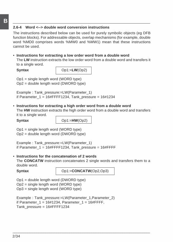
2/34___________________________________________________________________________
B2.6-4 Word <--> double word conversion instructions
The instructions described below can be used for purely symbolic objects (eg DFBfunction blocks). For addressable objects, overlap mechanisms (for example, doubleword %MD0 comprises words %MW0 and %MW1) mean that these instructionscannot be used.
• Instructions for extracting a low order word from a double wordThe LW instruction extracts the low order word from a double word and transfers itto a single word.
Syntax Op1:=LW(Op2)
Op1 = single length word (WORD type)Op2 = double length word (DWORD type)
Example : Tank_pressure:=LW(Parameter_1)if Parameter_1 = 16#FFFF1234, Tank_pressure = 16#1234
• Instructions for extracting a high order word from a double wordThe HW instruction extracts the high order word from a double word and transfersit to a single word.
Syntax Op1:=HW(Op2)
Op1 = single length word (WORD type)Op2 = double length word (DWORD type)
Example : Tank_pressure:=LW(Parameter_1)if Parameter_1 = 16#FFFF1234, Tank_pressure = 16#FFFF
• Instructions for the concatenation of 2 wordsThe CONCATW instruction concatenates 2 single words and transfers them to adouble word.
Syntax Op1:=CONCATW(Op2,Op3)
Op1 = double length word (DWORD type)Op2 = single length word (WORD type)Op3 = single length word (WORD type)
Example : Tank_pressure:=LW(Parameter_1,Parameter_2)if Parameter_1 = 16#1234, Parameter_1 = 16#FFFF,Tank_pressure = 16#FFFF1234
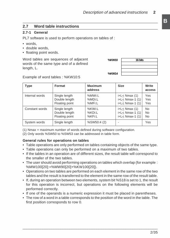
Description of advanced instructions 2
___________________________________________________________________________2/35
B2.7 Word table instructions
2.7-1 General
PL7 software is used to perform operations on tables of :
• words,• double words,• floating point words.
Word tables are sequences of adjacentwords of the same type and of a definedlength, L.
Example of word tables : %KW10:5
Type Format Maximum Size Writeaddress access
Internal words Single length %MWi:L i+L< Nmax (1) YesDouble length %MDi:L i+L< Nmax-1 (1) YesFloating point %MFi:L i+L< Nmax-1 (1) Yes
Constant words Single length %KWi:L i+L< Nmax (1) NoDouble length %KDi:L i+L< Nmax-1 (1) NoFloating point %KFi:L i+L< Nmax-1 (1) No
System words Single length %SW50:4 (2) - Yes
(1) Nmax = maximum number of words defined during software configuration.(2) Only words %SW50 to %SW53 can be addressed in table form.
General rules for operations on tables• Table operations are only performed on tables containing objects of the same type.• Table operations can only be performed on a maximum of two tables.• If the tables in an operation are of different sizes, the result table will correspond to
the smaller of the two tables.• The user should avoid performing operations on tables which overlap (for example :
%MW100[20]:=%MW90[20]+%KW100[20]).• Operations on two tables are performed on each element in the same row of the two
tables and the result is transferred to the element in the same row of the result table.• If, during an operation between two elements, system bit %S18 is set to 1, the result
for this operation is incorrect, but operations on the following elements will beperformed correctly.
• If one of the operands is a numeric expression it must be placed in parentheses.• The row of a word in a table corresponds to the position of the word in the table. The
first position corresponds to row 0.
16 bits%KW10
%KW14
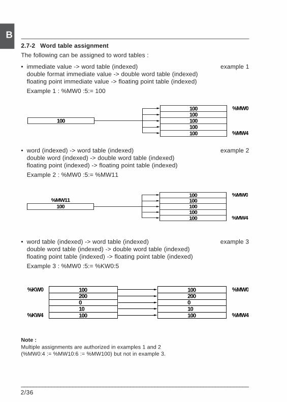
2/36___________________________________________________________________________
B2.7-2 Word table assignment
The following can be assigned to word tables :
• immediate value -> word table (indexed) example 1double format immediate value -> double word table (indexed)floating point immediate value -> floating point table (indexed)
Example 1 : %MW0 :5:= 100
• word (indexed) -> word table (indexed) example 2double word (indexed) -> double word table (indexed)floating point (indexed) -> floating point table (indexed)
Example 2 : %MW0 :5:= %MW11
• word table (indexed) -> word table (indexed) example 3double word table (indexed) -> double word table (indexed)floating point table (indexed) -> floating point table (indexed)
Example 3 : %MW0 :5:= %KW0:5
Note :Multiple assignments are authorized in examples 1 and 2(%MW0:4 := %MW10:6 := %MW100) but not in example 3.
%MW0
%MW4
100100
100100100
100
%MW0
%MW4
100100
100100100
100%MW11
%MW0
%MW4
200100
010100
200100
010100
%KW0
%KW4
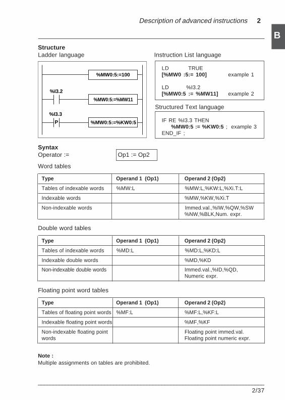
Description of advanced instructions 2
___________________________________________________________________________2/37
BStructureLadder language Instruction List language
LD TRUE[%MW0 :5:= 100] example 1
LD %I3.2[%MW0:5 := %MW11] example 2
Structured Text language
IF RE %I3.3 THEN%MW0:5 := %KW0:5 ; example 3
END_IF ;
SyntaxOperator := Op1 := Op2
Word tables
Type Operand 1 (Op1) Operand 2 (Op2)
Tables of indexable words %MW:L %MW:L,%KW:L,%Xi.T:L
Indexable words %MW,%KW,%Xi.T
Non-indexable words Immed.val.,%IW,%QW,%SW%NW,%BLK,Num. expr.
Double word tables
Type Operand 1 (Op1) Operand 2 (Op2)
Tables of indexable words %MD:L %MD:L,%KD:L
Indexable double words %MD,%KD
Non-indexable double words Immed.val.,%ID,%QD,Numeric expr.
Floating point word tables
Type Operand 1 (Op1) Operand 2 (Op2)
Tables of floating point words %MF:L %MF:L,%KF:L
Indexable floating point words %MF,%KF
Non-indexable floating point Floating point immed.val.words Floating point numeric expr.
Note :Multiple assignments on tables are prohibited.
%I3.2
%I3.3
%MW0:5:=100
%MW0:5:=%MW11
%MW0:5:=%KW0:5P
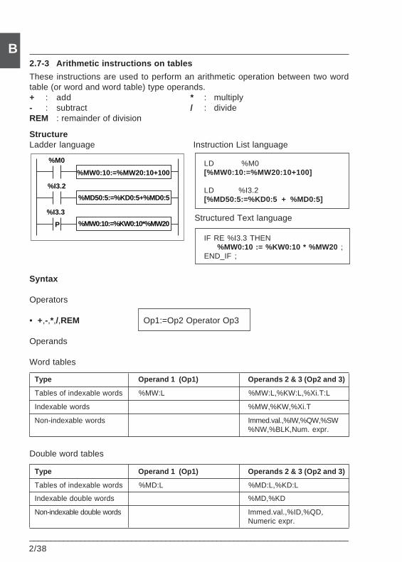
2/38___________________________________________________________________________
B2.7-3 Arithmetic instructions on tables
These instructions are used to perform an arithmetic operation between two wordtable (or word and word table) type operands.+ : add * : multiply- : subtract / : divideREM : remainder of division
StructureLadder language Instruction List language
LD %M0[%MW0:10:=%MW20:10+100]
LD %I3.2[%MD50:5:=%KD0:5 + %MD0:5]
Structured Text language
IF RE %I3.3 THEN%MW0:10 := %KW0:10 * %MW20 ;
END_IF ;
Syntax
Operators
• +,-,*,/,REM Op1:=Op2 Operator Op3
Operands
Word tables
Type Operand 1 (Op1) Operands 2 & 3 (Op2 and 3)
Tables of indexable words %MW:L %MW:L,%KW:L,%Xi.T:L
Indexable words %MW,%KW,%Xi.T
Non-indexable words Immed.val.,%IW,%QW,%SW%NW,%BLK,Num. expr.
Double word tables
Type Operand 1 (Op1) Operands 2 & 3 (Op2 and 3)
Tables of indexable words %MD:L %MD:L,%KD:L
Indexable double words %MD,%KD
Non-indexable double words Immed.val.,%ID,%QD,Numeric expr.
%I3.2
%I3.3
%MW0:10:=%MW20:10+100
%MD50:5:=%KD0:5+%MD0:5
%M0
P %MW0:10:=%KW0:10*%MW20
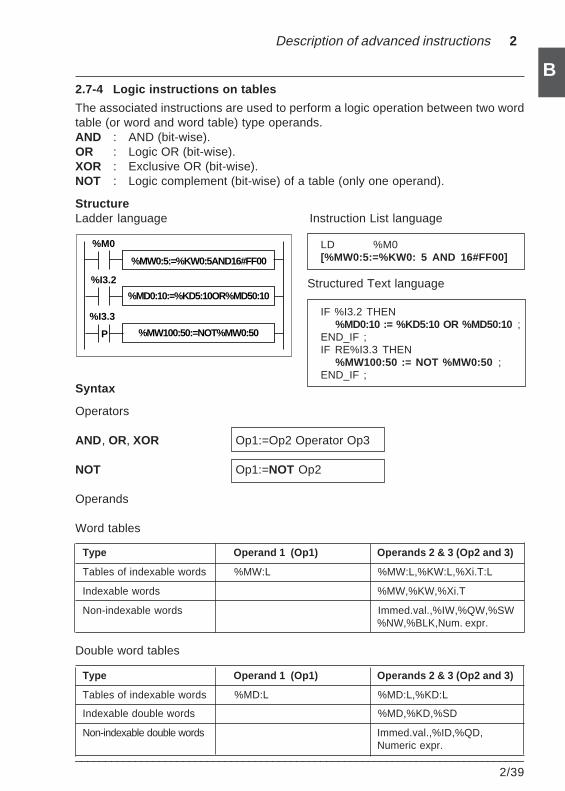
Description of advanced instructions 2
___________________________________________________________________________2/39
B2.7-4 Logic instructions on tables
The associated instructions are used to perform a logic operation between two wordtable (or word and word table) type operands.AND : AND (bit-wise).OR : Logic OR (bit-wise).XOR : Exclusive OR (bit-wise).NOT : Logic complement (bit-wise) of a table (only one operand).
StructureLadder language Instruction List language
LD %M0[%MW0:5:=%KW0: 5 AND 16#FF00]
Structured Text language
IF %I3.2 THEN%MD0:10 := %KD5:10 OR %MD50:10 ;
END_IF ;IF RE%I3.3 THEN
%MW100:50 := NOT %MW0:50 ;END_IF ;
Syntax
Operators
AND , OR, XOR Op1:=Op2 Operator Op3
NOT Op1:=NOT Op2
Operands
Word tables
Type Operand 1 (Op1) Operands 2 & 3 (Op2 and 3)
Tables of indexable words %MW:L %MW:L,%KW:L,%Xi.T:L
Indexable words %MW,%KW,%Xi.T
Non-indexable words Immed.val.,%IW,%QW,%SW%NW,%BLK,Num. expr.
Double word tables
Type Operand 1 (Op1) Operands 2 & 3 (Op2 and 3)
Tables of indexable words %MD:L %MD:L,%KD:L
Indexable double words %MD,%KD,%SD
Non-indexable double words Immed.val.,%ID,%QD,Numeric expr.
%I3.2
%I3.3
%MW0:5:=%KW0:5AND16#FF00
%MD0:10:=%KD5:10OR%MD50:10
%M0
P %MW100:50:=NOT%MW0:50
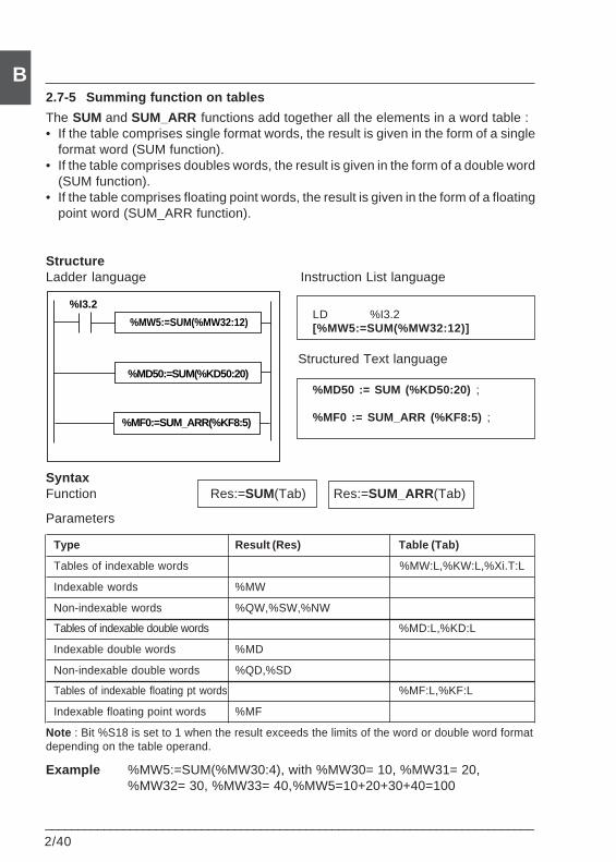
2/40___________________________________________________________________________
B2.7-5 Summing function on tables
The SUM and SUM_ARR functions add together all the elements in a word table :• If the table comprises single format words, the result is given in the form of a single
format word (SUM function).• If the table comprises doubles words, the result is given in the form of a double word
(SUM function).• If the table comprises floating point words, the result is given in the form of a floating
point word (SUM_ARR function).
StructureLadder language Instruction List language
LD %I3.2[%MW5:=SUM(%MW32:12)]
Structured Text language
%MD50 := SUM (%KD50:20) ;
%MF0 := SUM_ARR (%KF8:5) ;
SyntaxFunction Res:=SUM(Tab) Res:=SUM_ARR(Tab)
Parameters
Type Result (Res) Table (Tab)
Tables of indexable words %MW:L,%KW:L,%Xi.T:L
Indexable words %MW
Non-indexable words %QW,%SW,%NW
Tables of indexable double words %MD:L,%KD:L
Indexable double words %MD
Non-indexable double words %QD,%SD
Tables of indexable floating pt words %MF:L,%KF:L
Indexable floating point words %MF
Note : Bit %S18 is set to 1 when the result exceeds the limits of the word or double word formatdepending on the table operand.
Example %MW5:=SUM(%MW30:4), with %MW30= 10, %MW31= 20,%MW32= 30, %MW33= 40,%MW5=10+20+30+40=100
%MW5:=SUM(%MW32:12)
%MD50:=SUM(%KD50:20)
%I3.2
%MF0:=SUM_ARR(%KF8:5)
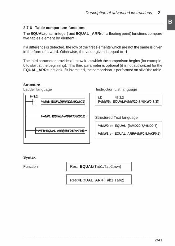
Description of advanced instructions 2
___________________________________________________________________________2/41
B2.7-6 Table comparison functions
The EQUAL (on an integer) and EQUAL _ARR (on a floating point) functions comparetwo tables element by element.
If a difference is detected, the row of the first elements which are not the same is givenin the form of a word. Otherwise, the value given is equal to -1.
The third parameter provides the row from which the comparison begins (for example,0 to start at the beginning). This third parameter is optional (it is not authorized for theEQUAL_ARR function). If it is omitted, the comparison is performed on all of the table.
StructureLadder language Instruction List language
LD %I3.2[%MW5:=EQUAL(%MW20:7,%KW0:7,3)]
Structured Text language
%MW0 := EQUAL (%MD20:7,%KD0:7)
%MW1 := EQUAL_ARR(%MF0:5,%KF0:5)
Syntax
Function Res:=EQUAL (Tab1,Tab2,row)
Res:=EQUAL_ARR (Tab1,Tab2)
%MW5:=EQUAL(%MW20:7,%KW0:7,3)
%MW0:=EQUAL(%MD20:7,%KD0:7)
%I3.2
%MF1:=EQUAL_ARR(%MF0:5,%KF0:5)
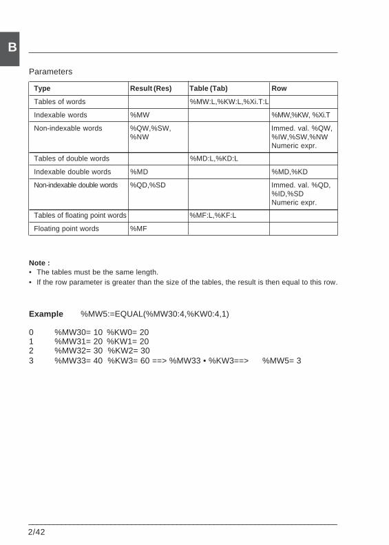
2/42___________________________________________________________________________
B
Parameters
Type Result (Res) Table (Tab) Row
Tables of words %MW:L,%KW:L,%Xi.T:L
Indexable words %MW %MW,%KW, %Xi.T
Non-indexable words %QW,%SW, Immed. val. %QW,%NW %IW,%SW,%NW
Numeric expr.
Tables of double words %MD:L,%KD:L
Indexable double words %MD %MD,%KD
Non-indexable double words %QD,%SD Immed. val. %QD,%ID,%SDNumeric expr.
Tables of floating point words %MF:L,%KF:L
Floating point words %MF
Note :• The tables must be the same length.• If the row parameter is greater than the size of the tables, the result is then equal to this row.
Example %MW5:=EQUAL(%MW30:4,%KW0:4,1)
0 %MW30= 10 %KW0= 201 %MW31= 20 %KW1= 202 %MW32= 30 %KW2= 303 %MW33= 40 %KW3= 60 ==> %MW33 • %KW3==> %MW5= 3
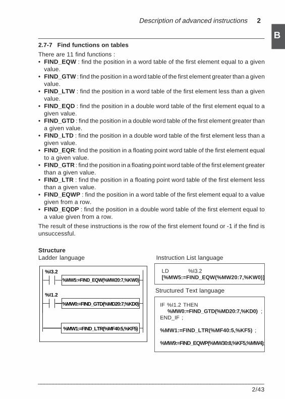
Description of advanced instructions 2
___________________________________________________________________________2/43
B2.7-7 Find functions on tables
There are 11 find functions :• FIND_EQW : find the position in a word table of the first element equal to a given
value.• FIND_GTW : find the position in a word table of the first element greater than a given
value.• FIND_LTW : find the position in a word table of the first element less than a given
value.• FIND_EQD : find the position in a double word table of the first element equal to a
given value.• FIND_GTD : find the position in a double word table of the first element greater than
a given value.• FIND_LTD : find the position in a double word table of the first element less than a
given value.• FIND_EQR: find the position in a floating point word table of the first element equal
to a given value.• FIND_GTR : find the position in a floating point word table of the first element greater
than a given value.• FIND_LTR : find the position in a floating point word table of the first element less
than a given value.• FIND_EQWP : find the position in a word table of the first element equal to a value
given from a row.• FIND_EQDP : find the position in a double word table of the first element equal to
a value given from a row.
The result of these instructions is the row of the first element found or -1 if the find isunsuccessful.
StructureLadder language Instruction List language
LD %I3.2[%MW5:=FIND_EQW(%MW20:7,%KW0)]
Structured Text language
IF %I1.2 THEN%MW0:=FIND_GTD(%MD20:7,%KD0) ;
END_IF ;
%MW1:=FIND_LTR(%MF40:5,%KF5) ;
%MW9:=FIND_EQWP(%MW30:8,%KF5,%MW4);
%MW5:=FIND_EQW(%MW20:7,%KW0)
%MW0:=FIND_GTD(%MD20:7,%KD0)
%I3.2
%I1.2
%MW1:=FIND_LTR(%MF40:5,%KF5)
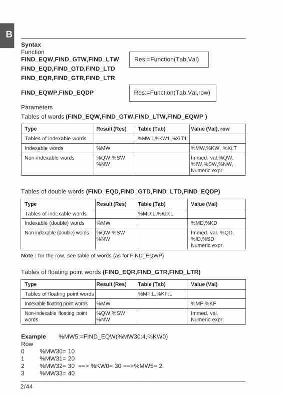
2/44___________________________________________________________________________
BSyntaxFunctionFIND_EQW,FIND_GTW,FIND_LTW Res:=Function(Tab,Val)
FIND_EQD,FIND_GTD,FIND_LTD
FIND_EQR,FIND_GTR,FIND_LTR
FIND_EQWP,FIND_EQDP Res:=Function(Tab,Val,row)
Parameters
Tables of words (FIND_EQW,FIND_GTW,FIND_LTW,FIND_EQWP )
Type Result (Res) Table (Tab) Value (Val), row
Tables of indexable words %MW:L,%KW:L,%Xi.T:L
Indexable words %MW %MW,%KW, %Xi.T
Non-indexable words %QW,%SW Immed. val.%QW,%NW %IW,%SW,%NW,
Numeric expr.
Tables of double words (FIND_EQD,FIND_GTD,FIND_LTD,FIND_EQDP)
Type Result (Res) Table (Tab) Value (Val)
Tables of indexable words %MD:L,%KD:L
Indexable (double) words %MW %MD,%KD
Non-indexable (double) words %QW,%SW Immed. val. %QD,%NW %ID,%SD
Numeric expr.
Note : for the row, see table of words (as for FIND_EQWP)
Tables of floating point words (FIND_EQR,FIND_GTR,FIND_LTR)
Type Result (Res) Table (Tab) Value (Val)
Tables of floating point words %MF:L,%KF:L
Indexable floating point words %MW %MF,%KF
Non-indexable floating point %QW,%SW Immed. val.words %NW Numeric expr.
Example %MW5:=FIND_EQW(%MW30:4,%KW0)Row0 %MW30= 101 %MW31= 202 %MW32= 30 ==> %KW0= 30 ==>%MW5= 23 %MW33= 40
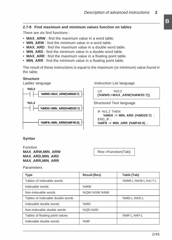
Description of advanced instructions 2
___________________________________________________________________________2/45
B2.7-8 Find maximum and minimum values function on tables
There are six find functions :
• MAX_ARW : find the maximum value in a word table.• MIN_ARW : find the minimum value in a word table.• MAX_ARD : find the maximum value in a double word table.• MIN_ARD : find the minimum value in a double word table.• MAX_ARR : find the maximum value in a floating point table.• MIN_ARR : find the minimum value in a floating point table.
The result of these instructions is equal to the maximum (or minimum) value found inthe table.
StructureLadder language Instruction List language
LD %I3.2[%MW5:=MAX_ARW(%MW20:7)]
Structured Text language
IF %I1.2 THEN%MD0 := MIN_ARD (%MD20:7) ;
END_IF ;%MF8 := MIN_ARR (%MF40:5) ;
Syntax
FunctionMAX_ARW,MIN_ARW Res:=Function(Tab)MAX_ARD,MIN_ARDMAX_ARR,MIN_ARR
Parameters
Type Result (Res) Table (Tab)
Tables of indexable words %MW:L,%KW:L,%Xi.T:L
Indexable words %MW
Non-indexable words %QW,%SW,%NW
Tables of indexable double words %MD:L,%KD:L
Indexable double words %MD
Non-indexable double words %QD,%SD
Tables of floating point values %MF:L,%KF:L
Indexable double words %MF
%MW5:=MAX_ARW(%MW20:7)
%MD0:=MIN_ARD(%MD20:7)
%I3.2
%I1.2
%MF8:=MIN_ARR(%MF40:5)
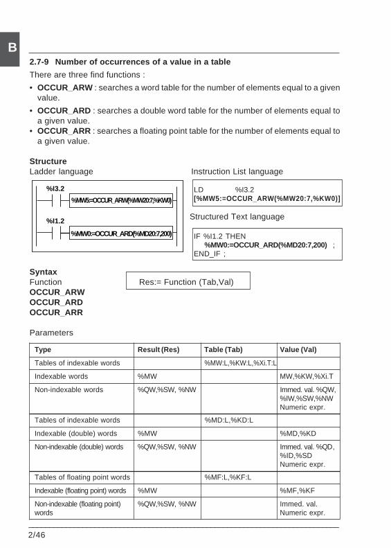
2/46___________________________________________________________________________
B2.7-9 Number of occurrences of a value in a table
There are three find functions :
• OCCUR_ARW : searches a word table for the number of elements equal to a givenvalue.
• OCCUR_ARD : searches a double word table for the number of elements equal toa given value.
• OCCUR_ARR : searches a floating point table for the number of elements equal toa given value.
StructureLadder language Instruction List language
LD %I3.2[%MW5:=OCCUR_ARW(%MW20:7,%KW0)]
Structured Text language
IF %I1.2 THEN%MW0:=OCCUR_ARD(%MD20:7,200) ;
END_IF ;
SyntaxFunction Res:= Function (Tab,Val)OCCUR_ARWOCCUR_ARDOCCUR_ARR
Parameters
Type Result (Res) Table (Tab) Value (Val)
Tables of indexable words %MW:L,%KW:L,%Xi.T:L
Indexable words %MW MW,%KW,%Xi.T
Non-indexable words %QW,%SW, %NW Immed. val. %QW,%IW,%SW,%NWNumeric expr.
Tables of indexable words %MD:L,%KD:L
Indexable (double) words %MW %MD,%KD
Non-indexable (double) words %QW,%SW, %NW Immed. val. %QD,%ID,%SDNumeric expr.
Tables of floating point words %MF:L,%KF:L
Indexable (floating point) words %MW %MF,%KF
Non-indexable (floating point) %QW,%SW, %NW Immed. val.words Numeric expr.
%MW5:=OCCUR_ARW(%MW20:7,%KW0)
%MW0:=OCCUR_ARD(%MD20:7,200)
%I3.2
%I1.2
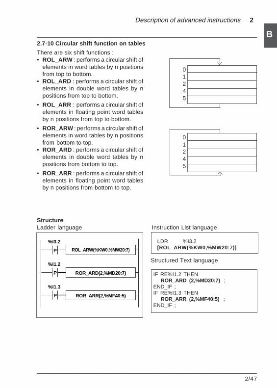
Description of advanced instructions 2
___________________________________________________________________________2/47
B2.7-10 Circular shift function on tables
There are six shift functions :• ROL_ARW : performs a circular shift of
elements in word tables by n positionsfrom top to bottom.
• ROL_ARD : performs a circular shift ofelements in double word tables by npositions from top to bottom.
• ROL_ARR : performs a circular shift ofelements in floating point word tablesby n positions from top to bottom.
• ROR_ARW : performs a circular shift ofelements in word tables by n positionsfrom bottom to top.
• ROR_ARD : performs a circular shift ofelements in double word tables by npositions from bottom to top.
• ROR_ARR : performs a circular shift ofelements in floating point word tablesby n positions from bottom to top.
StructureLadder language Instruction List language
LDR %I3.2[ROL_ARW(%KW0,%MW20:7)]
Structured Text language
IF RE%I1.2 THENROR_ARD (2,%MD20:7) ;
END_IF ;IF RE%I1.3 THEN
ROR_ARR (2,%MF40:5) ;END_IF ;
01245
01245
ROL_ARW(%KW0,%MW20:7)
ROR_ARD(2,%MD20:7)
%I3.2
%I1.2
P
P
ROR_ARR(2,%MF40:5)
%I1.3
P
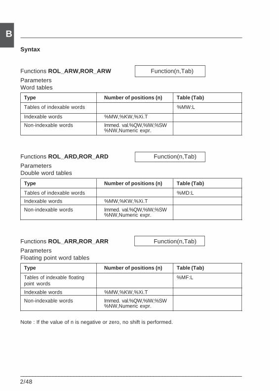
2/48___________________________________________________________________________
B
Syntax
Functions ROL_ARW,ROR_ARW Function(n,Tab)
ParametersWord tables
Type Number of positions (n) Table (Tab)
Tables of indexable words %MW:L
Indexable words %MW,%KW,%Xi.T
Non-indexable words Immed. val.%QW,%IW,%SW%NW,Numeric expr.
Functions ROL_ARD,ROR_ARD Function(n,Tab)
ParametersDouble word tables
Type Number of positions (n) Table (Tab)
Tables of indexable words %MD:L
Indexable words %MW,%KW,%Xi.T
Non-indexable words Immed. val.%QW,%IW,%SW%NW,Numeric expr.
Functions ROL_ARR,ROR_ARR Function(n,Tab)
ParametersFloating point word tables
Type Number of positions (n) Table (Tab)
Tables of indexable floating %MF:Lpoint words
Indexable words %MW,%KW,%Xi.T
Non-indexable words Immed. val.%QW,%IW,%SW%NW,Numeric expr.
Note : If the value of n is negative or zero, no shift is performed.
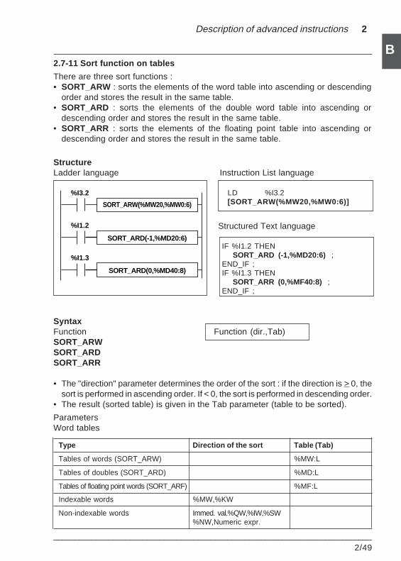
Description of advanced instructions 2
___________________________________________________________________________2/49
B2.7-11 Sort function on tables
There are three sort functions :• SORT_ARW : sorts the elements of the word table into ascending or descending
order and stores the result in the same table.• SORT_ARD : sorts the elements of the double word table into ascending or
descending order and stores the result in the same table.• SORT_ARR : sorts the elements of the floating point table into ascending or
descending order and stores the result in the same table.
StructureLadder language Instruction List language
LD %I3.2[SORT_ARW(%MW20,%MW0:6)]
Structured Text language
IF %I1.2 THENSORT_ARD (-1,%MD20:6) ;
END_IF ;IF %I1.3 THEN
SORT_ARR (0,%MF40:8) ;END_IF ;
SyntaxFunction Function (dir.,Tab)SORT_ARWSORT_ARDSORT_ARR
• The "direction" parameter determines the order of the sort : if the direction is > 0, thesort is performed in ascending order. If < 0, the sort is performed in descending order.
• The result (sorted table) is given in the Tab parameter (table to be sorted).
ParametersWord tables
Type Direction of the sort Table (Tab)
Tables of words (SORT_ARW) %MW:L
Tables of doubles (SORT_ARD) %MD:L
Tables of floating point words (SORT_ARF) %MF:L
Indexable words %MW,%KW
Non-indexable words Immed. val.%QW,%IW,%SW%NW,Numeric expr.
SORT_ARW(%MW20,%MW0:6)
SORT_ARD(-1,%MD20:6)
%I3.2
%I1.2
SORT_ARD(0,%MD40:8)
%I1.3
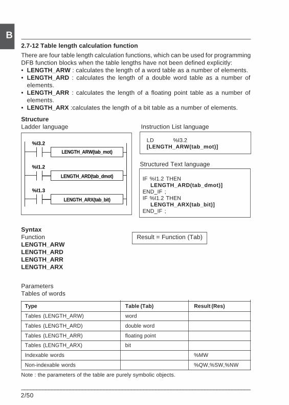
2/50___________________________________________________________________________
B2.7-12 Table length calculation function
There are four table length calculation functions, which can be used for programmingDFB function blocks when the table lengths have not been defined explicitly:• LENGTH_ARW : calculates the length of a word table as a number of elements.• LENGTH_ARD : calculates the length of a double word table as a number of
elements.• LENGTH_ARR : calculates the length of a floating point table as a number of
elements.• LENGTH_ARX :calculates the length of a bit table as a number of elements.
StructureLadder language Instruction List language
LD %I3.2[LENGTH_ARW(tab_mot)]
Structured Text language
IF %I1.2 THENLENGTH_ARD(tab_dmot)]
END_IF ;IF %I1.2 THEN
LENGTH_ARX(tab_bit)]END_IF ;
SyntaxFunction Result = Function (Tab)LENGTH_ARWLENGTH_ARDLENGTH_ARRLENGTH_ARX
ParametersTables of words
Type Table (Tab) Result (Res)
Tables (LENGTH_ARW) word
Tables (LENGTH_ARD) double word
Tables (LENGTH_ARR) floating point
Tables (LENGTH_ARX) bit
Indexable words %MW
Non-indexable words %QW,%SW,%NW
Note : the parameters of the table are purely symbolic objects.
LENGTH_ARW(tab_mot)
LENGTH_ARD(tab_dmot)
%I3.2
%I1.2
LENGTH_ARX(tab_bit)
%I1.3
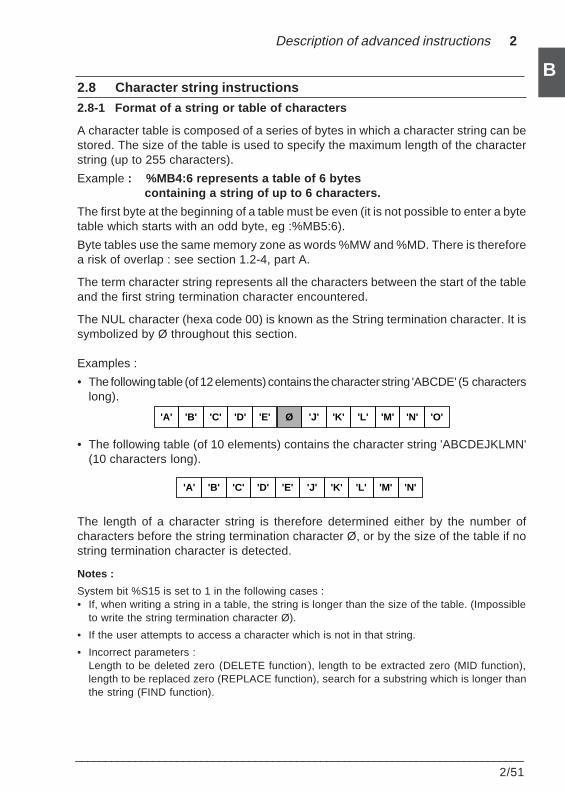
Description of advanced instructions 2
___________________________________________________________________________2/51
B2.8 Character string instructions
2.8-1 Format of a string or table of characters
A character table is composed of a series of bytes in which a character string can bestored. The size of the table is used to specify the maximum length of the characterstring (up to 255 characters).
Example : %MB4:6 represents a table of 6 bytes containing a string of up to 6 characters.
The first byte at the beginning of a table must be even (it is not possible to enter a bytetable which starts with an odd byte, eg :%MB5:6).
Byte tables use the same memory zone as words %MW and %MD. There is thereforea risk of overlap : see section 1.2-4, part A.
The term character string represents all the characters between the start of the tableand the first string termination character encountered.
The NUL character (hexa code 00) is known as the String termination character. It issymbolized by Ø throughout this section.
Examples :
• The following table (of 12 elements) contains the character string 'ABCDE' (5 characterslong).
• The following table (of 10 elements) contains the character string 'ABCDEJKLMN'(10 characters long).
The length of a character string is therefore determined either by the number ofcharacters before the string termination character Ø, or by the size of the table if nostring termination character is detected.
Notes :
System bit %S15 is set to 1 in the following cases :• If, when writing a string in a table, the string is longer than the size of the table. (Impossible
to write the string termination character Ø).
• If the user attempts to access a character which is not in that string.
• Incorrect parameters :Length to be deleted zero (DELETE function ), length to be extracted zero (MID function),length to be replaced zero (REPLACE function), search for a substring which is longer thanthe string (FIND function).
'A' 'B' 'C' 'D' 'E' 'J' 'K' 'L' 'M' 'N'
'A' 'B' 'C' 'D' 'E' Ø 'J' 'K' 'L' 'M' 'N' 'O'
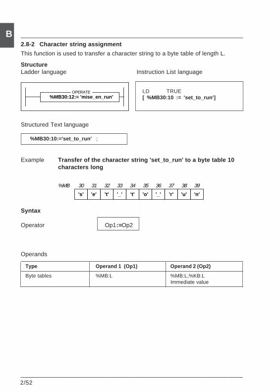
2/52___________________________________________________________________________
B2.8-2 Character string assignment
This function is used to transfer a character string to a byte table of length L.
StructureLadder language Instruction List language
LD TRUE[ %MB30:10 := 'set_to_run']
Structured Text language
%MB30:10:='set_to_run' ;
Example Transfer of the character string 'set_to_run' to a byte table 10characters long
Syntax
Operator Op1:=Op2
Operands
Type Operand 1 (Op1) Operand 2 (Op2)
Byte tables %MB:L %MB:L,%KB:LImmediate value
%MB30:12:= 'mise_en_run' OPERATE
's' 'e' 't' '_' 't' 'o' '_' 'r' 'u' 'n'
%MB 30 31 32 33 34 35 36 37 38 39
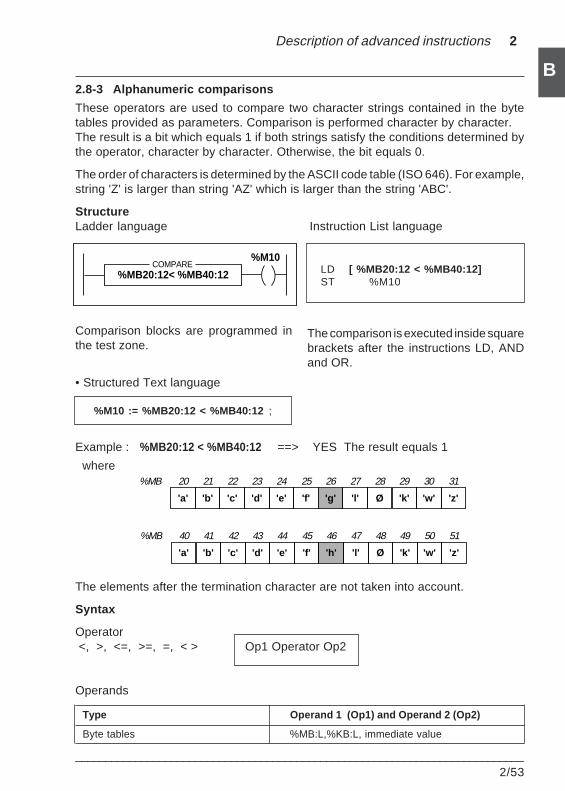
Description of advanced instructions 2
___________________________________________________________________________2/53
B2.8-3 Alphanumeric comparisons
These operators are used to compare two character strings contained in the bytetables provided as parameters. Comparison is performed character by character.The result is a bit which equals 1 if both strings satisfy the conditions determined bythe operator, character by character. Otherwise, the bit equals 0.
The order of characters is determined by the ASCII code table (ISO 646). For example,string 'Z' is larger than string 'AZ' which is larger than the string 'ABC'.
StructureLadder language Instruction List language
LD [ %MB20:12 < %MB40:12]ST %M10
Comparison blocks are programmed inthe test zone.
• Structured Text language
%M10 := %MB20:12 < %MB40:12 ;
Example : %MB20:12 < %MB40:12 ==> YES The result equals 1
where
The elements after the termination character are not taken into account.
Syntax
Operator <, >, <=, >=, =, < > Op1 Operator Op2
Operands
Type Operand 1 (Op1) and Operand 2 (Op2)
Byte tables %MB:L,%KB:L, immediate value
The comparison is executed inside squarebrackets after the instructions LD, ANDand OR.
%MB20:12< %MB40:12COMPARE
%M10
'a' 'b' 'c' 'd' 'e' 'f' 'h' 'l' Ø 'k' 'w' 'z'
%MB 40 41 42 43 44 45 46 47 48 49 50 51
'a' 'b' 'c' 'd' 'e' 'f' 'g' 'l' Ø 'k' 'w' 'z'
%MB 20 21 22 23 24 25 26 27 28 29 30 31
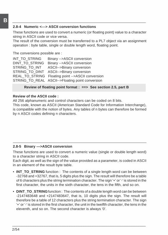
2/54___________________________________________________________________________
B2.8-4 Numeric <---> ASCII conversion functions
These functions are used to convert a numeric (or floating point) value to a characterstring in ASCII code or vice versa.The result of the conversion must be transferred to a PL7 object via an assignmentoperation : byte table, single or double length word, floating point.
The conversions possible are :
INT_TO_STRING Binary -->ASCII conversionDINT_TO_STRING Binary -->ASCII conversionSTRING_TO_INT ASCII-->Binary conversionSTRING_TO_DINT ASCII-->Binary conversionREAL_TO_STRING Floating point -->ASCII conversionSTRING_TO_REAL ASCII-->Floating point conversion
Review of floating point format : ==> See section 2.5, part B
Review of the ASCII code :All 256 alphanumeric and control characters can be coded on 8 bits.This code, known as ASCII (American Standard Code for Information Interchange),is compatible with the notion of bytes. Any tables of n bytes can therefore be formedby n ASCII codes defining n characters.
2.8-5 Binary --->ASCII conversion
These functions are used to convert a numeric value (single or double length word)to a character string in ASCII code.Each digit, as well as the sign of the value provided as a parameter, is coded in ASCIIin an element of the result byte table.
• INT_TO_STRING function : The contents of a single length word can be between-32768 and +32767, that is, 5 digits plus the sign. The result will therefore be a tableof 6 characters plus the string termination character. The sign '+' or '-' is stored in thefirst character, the units in the sixth character, the tens in the fifth, and so on.
• DINT_TO_STRING function : The contents of a double length word can be between-2147483648 and +2147483647, that is, 10 digits plus the sign. The result willtherefore be a table of 12 characters plus the string termination character. The sign'+' or '-' is stored in the first character, the unit in the twelfth character, the tens in theeleventh, and so on. The second character is always '0'.
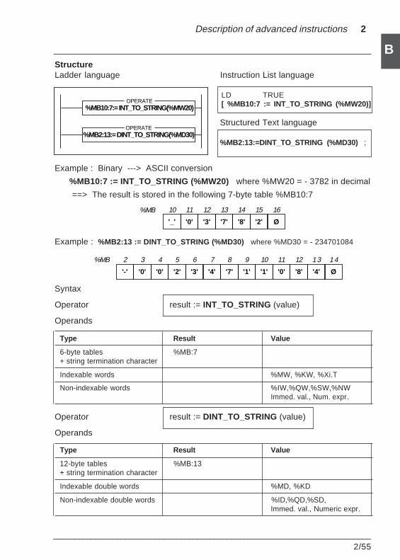
Description of advanced instructions 2
___________________________________________________________________________2/55
BStructureLadder language Instruction List language
LD TRUE[ %MB10:7 := INT_TO_STRING (%MW20)]
Structured Text language
%MB2:13:=DINT_TO_STRING (%MD30) ;
Example : Binary ---> ASCII conversion
%MB10:7 := INT_TO_STRING (%MW20) where %MW20 = - 3782 in decimal
==> The result is stored in the following 7-byte table %MB10:7
Example : %MB2:13 := DINT_TO_STRING (%MD30) where %MD30 = - 234701084
Syntax
Operator result := INT_TO_STRING (value)
Operands
Type Result Value
6-byte tables %MB:7+ string termination character
Indexable words %MW, %KW, %Xi.T
Non-indexable words %IW,%QW,%SW,%NWImmed. val., Num. expr.
Operator result := DINT_TO_STRING (value)
Operands
Type Result Value
12-byte tables %MB:13+ string termination character
Indexable double words %MD, %KD
Non-indexable double words %ID,%QD,%SD,Immed. val., Numeric expr.
'-' '0' '0' '2' '3' '4' '7' '1' '1' '0' '8' '4'
%MB 2 3 4 5 6 7 8 9 10 11 12 1 3
Ø
1 4
'_' '0' '3' '7' '8' '2' Ø
%MB 10 11 12 13 14 15 16
%MB10:7:= INT_TO_STRING(%MW20)OPERATE
%MB2:13:= DINT_TO_STRING(%MD30)OPERATE
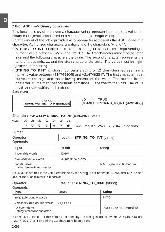
2/56___________________________________________________________________________
B
==> result %MW13 = -2347 in decimal
2.8-6 ASCII ---> Binary conversion
This function is used to convert a character string representing a numeric value intobinary code (result transferred to a single or double length word).Each element of the table provided as a parameter represents the ASCII code of acharacter. Authorized characters are digits and the characters '+' and '-'.• STRING_TO_INT function : converts a string of 6 characters representing a
numeric value between -32768 and +32767. The first character must represent thesign and the following characters the value. The second character represents thetens of thousands, ..., and the sixth character the units. The value must be right-justified in the string.
• STRING_TO_DINT function : converts a string of 12 characters representing anumeric value between -2147483648 and +2147483647. The first character mustrepresent the sign and the following characters the value. The second is thecharacter '0', the third the thousands of millions,..., the twelfth the units. The valuemust be right-justified in the string.
Structure
LD TRUE[%MW13 := STRING_TO_INT (%MB20:7)]
Example : %MW13 := STRING_TO_INT (%MB20:7) where
Syntax
Operator result := STRING_TO_INT (string)Operands
Type Result String
Indexable words %MW
Non-indexable words %QW,%SW,%NW.
6-byte tables %MB:7,%KB:7, Immed. val.+ string termination character
Bit %S18 is set to 1 if the value described by the string is not between -32768 and +32767 or ifone of the 6 characters is incorrect.
Operator result := STRING_TO_DINT (string)Operands
Type Result String
Indexable double words %MD
Non-indexable double words %QD,%SD
12-byte tables %MB:13,%KB:13, Immed. val.+ string termination character
Bit %S18 is set to 1 if the value described by the string is not between -2147483648 and+2147483647 or if one of the 12 characters is incorrect.
'_' '0' '2' '3' '4' '7' Ø
%MB 20 21 22 23 24 25 2 6
%MW13:= STRING_TO_INT(%MB20:7)OPERATE
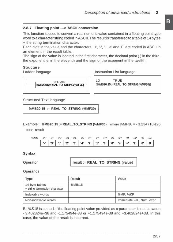
Description of advanced instructions 2
___________________________________________________________________________2/57
B2.8-7 Floating point ---> ASCII conversion
This function is used to convert a real numeric value contained in a floating point typeword to a character string coded in ASCII. The result is transferred to a table of 14 bytes+ the string termination character.Each digit in the value and the characters '+', '-', '.', 'e' and 'E' are coded in ASCII inan element in the result table.The sign of the value is located in the first character, the decimal point (.) in the third,the exponent 'e' in the eleventh and the sign of the exponent in the twelfth.
StructureLadder language Instruction List language
LD TRUE[ %MB20:15 := REAL_TO_STRING (%MF30)]
Structured Text language
%MB20:15 := REAL_TO_STRING (%MF30) ;
Example : %MB20:15 := REAL_TO_STRING (%MF30) where %MF30 = - 3.234718 e26
==> result
Syntax
Operator result := REAL_TO_STRING (value)
Operands
Type Result Value
14-byte tables %MB:15+ string termination character
Indexable words %MF, %KF
Non-indexable words Immediate val., Num. expr.
Bit %S18 is set to 1 if the floating point value provided as a parameter is not between- 3.402824e+38 and -1.175494e-38 or +1.175494e-38 and +3.402824e+38. In thiscase, the value of the result is incorrect.
'-' '3' '.' '2' '3' '4' '7' '1' '8' '0' 'e' '+'
%MB 20 21 22 23 24 25 26 27 28 29 30 31
'2' '6' Ø
32 33 34
%MB20:15:=REAL_TO_STRING(%MF30)OPERATE
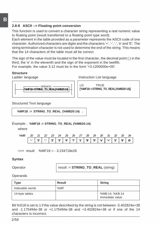
2/58___________________________________________________________________________
B2.8-8 ASCII --> Floating point conversion
This function is used to convert a character string representing a real numeric valueto floating point (result transferred to a floating point type word).Each element in the table provided as a parameter represents the ASCII code of onecharacter. Authorized characters are digits and the characters '+', '-', '.', 'e' and 'E'. Thestring termination character is not used to determine the end of the string. This meansthat the 14 characters of the table must all be correct.
The sign of the value must be located in the first character, the decimal point (.) in thethird, the 'e' in the eleventh and the sign of the exponent in the twelfth.For example, the value 3.12 must be in the form '+3.1200000e+00'.
StructureLadder language Instruction List language
LD TRUE[ %MF18 := STRING_TO_REAL (%MB20:14)]
Structured Text language
%MF18 := STRING_TO_REAL (%MB20:14) ;
Example : %MF18 := STRING_TO_REAL (%MB20:14)
where
==> result %MF18 = - 3.234718e26
Syntax
Operator result := STRING_TO_REAL (string)
Operands
Type Result String
Indexable words %MF
14-byte tables %MB:14, %KB:14Immediate value
Bit %S18 is set to 1 if the value described by the string is not between -3.402824e+38and -1.175494e-38 or +1.175494e-38 and +3.402824e+38 or if one of the 14characters is incorrect.
'-' '3' '.' '2' '3' '4' '7' '1' '8' '0' 'e' '+'
%MB 20 21 22 23 24 25 26 27 28 29 30 31
'2' '6' Ø
32 33 34
%MF18:=STRING_TO_REAL(%MB20:14)OPERATE
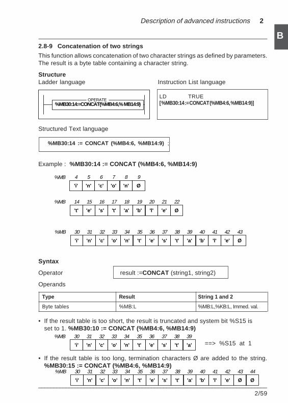
Description of advanced instructions 2
___________________________________________________________________________2/59
B2.8-9 Concatenation of two strings
This function allows concatenation of two character strings as defined by parameters.The result is a byte table containing a character string.
StructureLadder language Instruction List language
LD TRUE[ %MB30:14 := CONCAT (%MB4:6, %MB14:9)]
Structured Text language
%MB30:14 := CONCAT (%MB4:6, %MB14:9) ;
Example : %MB30:14 := CONCAT (%MB4:6, %MB14:9)
Syntax
Operator result :=CONCAT (string1, string2)
Operands
Type Result String 1 and 2
Byte tables %MB:L %MB:L,%KB:L, Immed. val.
• If the result table is too short, the result is truncated and system bit %S15 isset to 1. %MB30:10 := CONCAT (%MB4:6, %MB14:9)
• If the result table is too long, termination characters Ø are added to the string.%MB30:15 := CONCAT (%MB4:6, %MB14:9)
==> %S15 at 1'i' 'n' 'c' 'o' 'n' 't' 'e' 's' 't' 'a'
%MB 30 31 32 33 34 35 36 37 38 39
'i' 'n' 'c' 'o' 'n' 't' 'e' 's' 't' 'a' 'b' 'l'
%MB 30 31 32 33 34 35 36 37 38 39 40 41
'e' Ø
42 43
Ø
44
'i' 'n' 'c' 'o' 'n' 't' 'e' 's' 't' 'a' 'b' 'l'
%MB 30 31 32 33 34 35 36 37 38 39 40 41
'e' Ø
42 43
't' 'e' 's' 't' 'a' 'b' 'l' 'e' Ø
%MB 14 15 16 17 18 19 20 21 22
'i' 'n' 'c' 'o' 'n' Ø
%MB 4 5 6 7 8 9
%MB30:14:=CONCAT(%MB4:6,% MB14:9)OPERATE
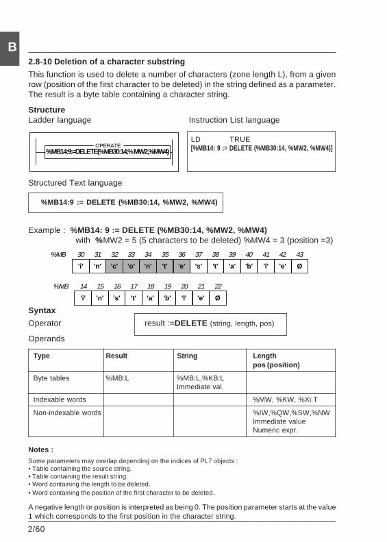
2/60___________________________________________________________________________
B2.8-10 Deletion of a character substring
This function is used to delete a number of characters (zone length L), from a givenrow (position of the first character to be deleted) in the string defined as a parameter.The result is a byte table containing a character string.
StructureLadder language Instruction List language
LD TRUE[%MB14: 9 := DELETE (%MB30:14, %MW2, %MW4)]
Structured Text language
%MB14:9 := DELETE (%MB30:14, %MW2, %MW4) ;
Example : %MB14: 9 := DELETE (%MB30:14, %MW2, %MW4) with %MW2 = 5 (5 characters to be deleted) %MW4 = 3 (position =3)
Syntax
Operator result :=DELETE (string, length, pos)
Operands
Type Result String Lengthpos (position)
Byte tables %MB:L %MB:L,%KB:LImmediate val.
Indexable words %MW, %KW, %Xi.T
Non-indexable words %IW,%QW,%SW,%NWImmediate valueNumeric expr.
Notes :
Some parameters may overlap depending on the indices of PL7 objects :• Table containing the source string.• Table containing the result string.• Word containing the length to be deleted.• Word containing the position of the first character to be deleted.
A negative length or position is interpreted as being 0. The position parameter starts at the value1 which corresponds to the first position in the character string.
'i' 'n' 'c' 'o' 'n' 't' 'e' 's' 't' 'a' 'b' 'l'
%MB 30 31 32 33 34 35 36 37 38 39 40 41
'e' Ø
42 43
'i' 'n' 's' 't' 'a' 'b' 'l' 'e' Ø
%MB 14 15 16 17 18 19 20 21 22
%MB14:9:=DELETE(%MB30:14,% MW2,%MW4)OPERATE
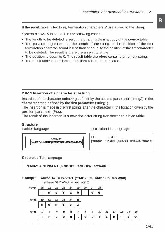
Description of advanced instructions 2
___________________________________________________________________________2/61
BIf the result table is too long, termination characters Ø are added to the string.
System bit %S15 is set to 1 in the following cases :
• The length to be deleted is zero, the output table is a copy of the source table.• The position is greater than the length of the string, or the position of the first
termination character found is less than or equal to the position of the first characterto be deleted. The result is therefore an empty string.
• The position is equal to 0. The result table therefore contains an empty string.• The result table is too short. It has therefore been truncated.
2.8-11 Insertion of a character substring
Insertion of the character substring defined by the second parameter (string2) in thecharacter string defined by the first parameter (string1).The insertion is made in the first string, after the character in the location given by theposition parameter (Pos).The result of the insertion is a new character string transferred to a byte table.
StructureLadder language Instruction List language
LD TRUE[%MB2:14 := INSERT (%MB20:9, %MB30:6, %MW40)]
Structured Text language
%MB2:14 := INSERT (%MB20:9, %MB30:6, %MW40) ;
Example : %MB2:14 := INSERT (%MB20:9, %MB30:6, %MW40)where % MW40 := position 2
'i' 'n' 'c' 'o' 'n' 't' 'e' 's' 't' 'a' 'b' 'l'
%MB 2 3 4 5 6 7 8 9 10 11 12 13
'e' Ø
14 15
'c' 'o' 'n' 't' 'e' Ø
%MB 30 31 32 33 34 35
'i' 'n' 's' 't' 'a' 'b' 'l' 'e' Ø
%MB 20 21 22 23 24 25 26 27 28
%MB2: 14:=INSERT(%MB20:9,% MB30:6,%MW40)OPERATE
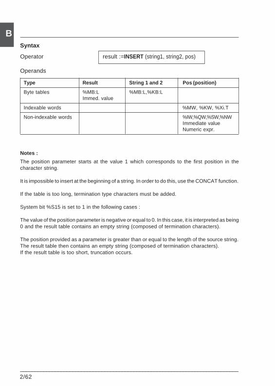
2/62___________________________________________________________________________
BSyntax
Operator result :=INSERT (string1, string2, pos)
Operands
Type Result String 1 and 2 Pos (position)
Byte tables %MB:L %MB:L,%KB:LImmed. value
Indexable words %MW, %KW, %Xi.T
Non-indexable words %IW,%QW,%SW,%NWImmediate valueNumeric expr.
Notes :
The position parameter starts at the value 1 which corresponds to the first position in thecharacter string.
It is impossible to insert at the beginning of a string. In order to do this, use the CONCAT function.
If the table is too long, termination type characters must be added.
System bit %S15 is set to 1 in the following cases :
The value of the position parameter is negative or equal to 0. In this case, it is interpreted as being0 and the result table contains an empty string (composed of termination characters).
The position provided as a parameter is greater than or equal to the length of the source string.The result table then contains an empty string (composed of termination characters).If the result table is too short, truncation occurs.
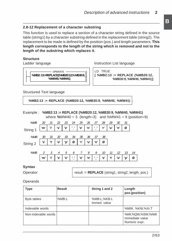
Description of advanced instructions 2
___________________________________________________________________________2/63
B2.8-12 Replacement of a character substring
This function is used to replace a section of a character string defined in the sourcetable (string1) by a character substring defined in the replacement table (string2). Thereplacement to be made is defined by the position (pos.) and length parameters. Thislength corresponds to the length of the string which is removed and not to thelength of the substring which replaces it.
StructureLadder language Instruction List language
LD TRUE[ %MB2:13 := REPLACE (%MB20:12, %MB30:9, %MW40, %MW41)]
Structured Text language
%MB2:13 := REPLACE (%MB20:12, %MB30:9, %MW40, %MW41) ;
Example : %MB2:13 := REPLACE (%MB20:12, %MB30:9, %MW40, %MW41)where %MW40 = 3 (length=3) and %MW41 = 9 (position=9)
Syntax
Operator result := REPLACE (string1, string2, length, pos.)
Operands
Type Result String 1 and 2 Lengthpos (position)
Byte tables %MB:L %MB:L,%KB:LImmed. value
Indexable words %MW, %KW,%Xi.T
Non-indexable words %IW,%QW,%SW,%NWImmediate valueNumeric expr.
String 1
String 2
'm' 'i' 's' 'e' '_' 'e' 'n' '_' 's' 't' 'o' 'p'
%MB 2 3 4 5 6 7 8 9 10 11 12 13
Ø
14
's' 't' 'o' 'p' Ø 'r'
%MB 30 31 32 33 34 35
'u' 'n' Ø
36 37 38
'm' 'i' 's' 'e' '_' 'e' 'n' '_' 'r' 'u' 'n' Ø
%MB 20 21 22 23 24 25 26 27 28 29 30 31
%MB2: 13:=REPLACE(%MB20:12,% MB30:9,%MW40, %MW41)
OPERATE
2/64___________________________________________________________________________
BNotes :
The position parameter starts at the value 1 which corresponds to the first position in thecharacter string.
If the output table is too long, termination type characters are added to the string.
System bit %S15 is set to 1 in the following cases :
• If the value of the position parameter is negative or equal to 0. In this case, it is interpreted asbeing 0 and the result table contains an empty string (composed of termination characters).
• If the position provided as a parameter is greater than or equal to the length of the source string,the result table then contains an empty string (composed of termination characters).
• If the result table is too short, truncation occurs.
• If the position of the first string termination character is less than or equal to the position of thefirst character to be replaced, the output table is a copy of the source table up to the stringtermination character and completed by termination characters.
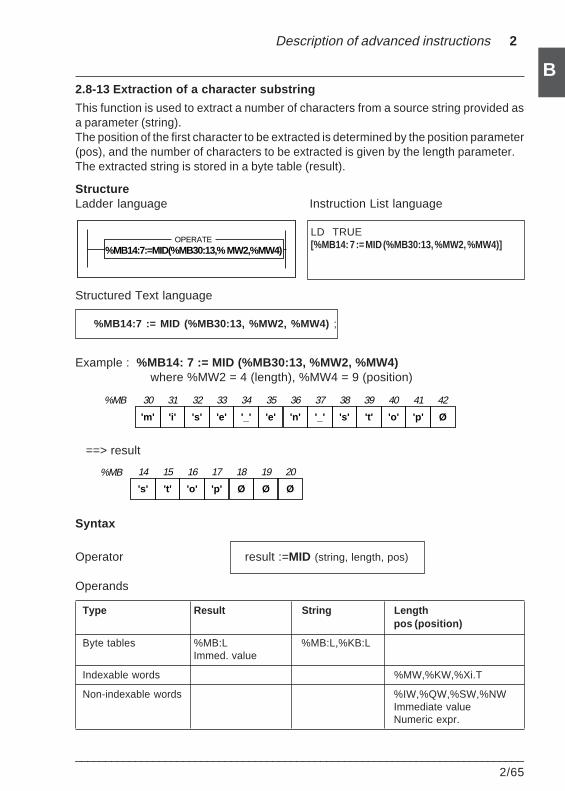
Description of advanced instructions 2
___________________________________________________________________________2/65
B2.8-13 Extraction of a character substring
This function is used to extract a number of characters from a source string provided asa parameter (string).The position of the first character to be extracted is determined by the position parameter(pos), and the number of characters to be extracted is given by the length parameter.The extracted string is stored in a byte table (result).
StructureLadder language Instruction List language
LD TRUE[%MB14: 7 := MID (%MB30:13, %MW2, %MW4)]
Structured Text language
%MB14:7 := MID (%MB30:13, %MW2, %MW4) ;
Example : %MB14: 7 := MID (%MB30:13, %MW2, %MW4)where %MW2 = 4 (length), %MW4 = 9 (position)
==> result
Syntax
Operator result :=MID (string, length, pos)
Operands
Type Result String Lengthpos (position)
Byte tables %MB:L %MB:L,%KB:LImmed. value
Indexable words %MW,%KW,%Xi.T
Non-indexable words %IW,%QW,%SW,%NWImmediate valueNumeric expr.
's' 't' 'o' 'p' Ø Ø
%MB 14 15 16 17 18 19
Ø
20
'm' 'i' 's' 'e' '_' 'e' 'n' '_' 's' 't' 'o' 'p'
%MB 30 31 32 33 34 35 36 37 38 39 40 41
Ø
42
%MB14:7:=MID(%MB30:13,% MW2,%MW4)OPERATE
2/66___________________________________________________________________________
BNotes :
The position parameter starts at value 1 which corresponds to the first position in the characterstring.
If the output table is too long, termination type characters are added to the result string.
If the length provided as a parameter is greater than the size of the source string, the result tablethen contains the source string.
If the last element of the table or the string termination character is reached before the numberof characters defined by the length parameter has been extracted, extraction stops at this point.
System bit %S15 is set to 1 in the following cases :
• If the value of the length parameter to be extracted is negative or equal to 0. In this case, it isinterpreted as being 0 and the result table contains an empty string (composed of terminationcharacters).
• If the value of the position parameter for the beginning of the extraction is zero or greater thanor equal to the length of the table, or greater than or equal to the position of the first terminationcharacter. In this case, the result table contains an empty string (composed of terminationcharacters).
• If the result table is too short, truncation occurs.
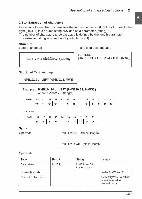
Description of advanced instructions 2
___________________________________________________________________________2/67
B2.8-14 Extraction of characters
Extraction of a number of characters the furthest to the left (LEFT) or furthest to theright (RIGHT) in a source string provided as a parameter (string).The number of characters to be extracted is defined by the length parameter.The extracted string is stored in a byte table (result).
StructureLadder language Instruction List language
LD TRUE[%MB10: 10 := LEFT (%MB30:13, %MW2)]
Structured Text language
%MB10:10 := LEFT (%MB30:13, MW2) ;
Example : %MB10: 10 := LEFT (%MB30:13, %MW2)where %MW2 = 8 (length)
==> result
Syntax
Operator result :=LEFT (string, length)
result :=RIGHT (string, length)
Operands
Type Result String Length
Byte tables %MB:L %MB:L,%KB:LImmed. value
Indexable words %MW,%KW,%Xi.T
Non-indexable words %IW,%QW,%SW,%NWImmediate valueNumeric expr.
'm' 'i' 's' 'e' '_' 'e' 'n' '_' Ø Ø
%MB 10 11 12 13 14 15 16 17 18 19
'm' 'i' 's' 'e' '_' 'e' 'n' '_' 's' 't' 'o' 'p'
%MB 30 31 32 33 34 35 36 37 38 39 40 41
Ø
42
%MB10:10:=LEFT(%MB30:13,% MW2)OPERATE
2/68___________________________________________________________________________
BNotes :
If the output table is too long, termination type characters are added to the result string.
If the length provided as a parameter is greater than the size of the source string, the result tablethen contains the source string.
System bit %S15 is set to 1 in the following cases :
• If the value of the length parameter to be extracted is negative or 0. In this case, the result tablecontains an empty string (composed of termination characters).• If the result table is too short, truncation occurs.
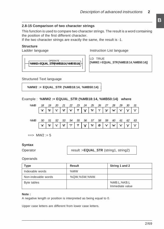
Description of advanced instructions 2
___________________________________________________________________________2/69
B2.8-15 Comparison of two character strings
This function is used to compare two character strings. The result is a word containingthe position of the first different character.If the two character strings are exactly the same, the result is -1.
StructureLadder language Instruction List language
LD TRUE[%MW2 := EQUAL_STR (%MB18:14, %MB50:14)]
Structured Text language
%MW2 := EQUAL_STR (%MB18:14, %MB50:14) ;
Example : %MW2 := EQUAL_STR (%MB18:14, %MB50:14) where
==> MW2 := 5
Syntax
Operator result :=EQUAL_STR (string1, string2)
Operands
Type Result String 1 and 2
Indexable words %MW
Non-indexable words %QW,%SW,%NW.
Byte tables %MB:L,%KB:LImmediate value
Note :A negative length or position is interpreted as being equal to 0.
Upper case letters are different from lower case letters.
'a' 'b' 'c' 'd' 'e' 'f' 'g' 'h' 'i' 'p' 'w' 'x'
%MB 18 19 20 21 22 23 24 25 26 27 28 29
'y' 'z'
30 31
'a' 'b' 'c' 'd' '?' 'f' 'g' 'h' Ø 'v' 'w' 'x'
%MB 50 51 52 53 54 55 56 57 58 59 60 61
'y' 'z'
62 63
%MW2:= EQUAL_STR(%MB18:14, %MB 50:14)OPERATE
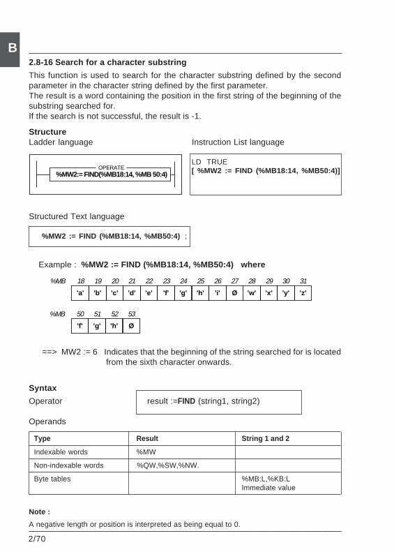
2/70___________________________________________________________________________
B2.8-16 Search for a character substring
This function is used to search for the character substring defined by the secondparameter in the character string defined by the first parameter.The result is a word containing the position in the first string of the beginning of thesubstring searched for.If the search is not successful, the result is -1.
StructureLadder language Instruction List language
LD TRUE[ %MW2 := FIND (%MB18:14, %MB50:4)]
Structured Text language
%MW2 := FIND (%MB18:14, %MB50:4) ;
Example : %MW2 := FIND (%MB18:14, %MB50:4) where
==> MW2 := 6 Indicates that the beginning of the string searched for is located from the sixth character onwards.
Syntax
Operator result :=FIND (string1, string2)
Operands
Type Result String 1 and 2
Indexable words %MW
Non-indexable words %QW,%SW,%NW.
Byte tables %MB:L,%KB:LImmediate value
Note :
A negative length or position is interpreted as being equal to 0.
'f' 'g' 'h' Ø
%MB 50 51 52 53
'a' 'b' 'c' 'd' 'e' 'f' 'g' 'h' 'i' Ø 'w' 'x'
%MB 18 19 20 21 22 23 24 25 26 27 28 29
'y' 'z'
30 31
%MW2:= FIND(%MB18:14, %MB 50:4)OPERATE
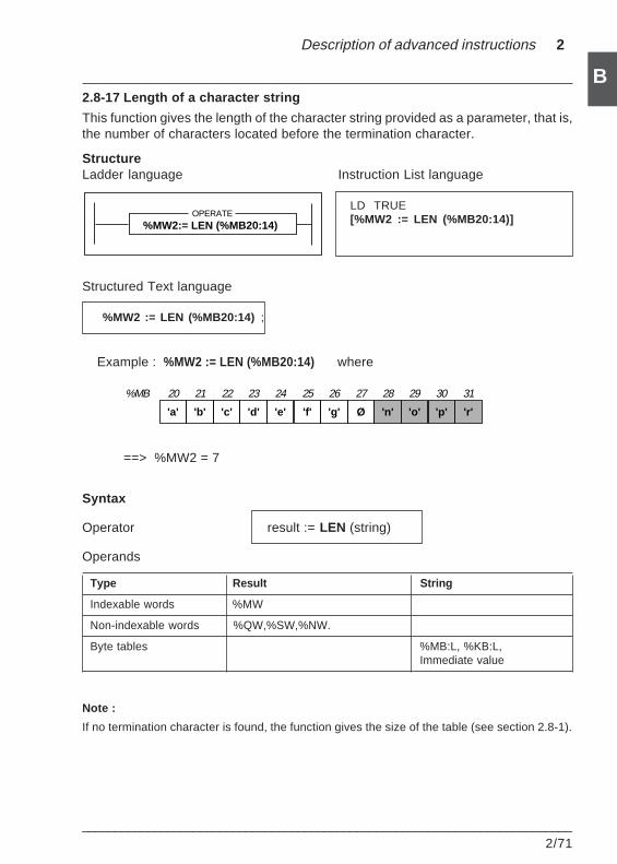
Description of advanced instructions 2
___________________________________________________________________________2/71
B2.8-17 Length of a character string
This function gives the length of the character string provided as a parameter, that is,the number of characters located before the termination character.
StructureLadder language Instruction List language
LD TRUE[%MW2 := LEN (%MB20:14)]
Structured Text language
%MW2 := LEN (%MB20:14) ;
Example : %MW2 := LEN (%MB20:14) where
==> %MW2 = 7
Syntax
Operator result := LEN (string)
Operands
Type Result String
Indexable words %MW
Non-indexable words %QW,%SW,%NW.
Byte tables %MB:L, %KB:L,Immediate value
Note :
If no termination character is found, the function gives the size of the table (see section 2.8-1).
'a' 'b' 'c' 'd' 'e' 'f' 'g' Ø 'n' 'o' 'p' 'r'
%MB 20 21 22 23 24 25 26 27 28 29 30 31
%MW2:= LEN (%MB20:14)OPERATE
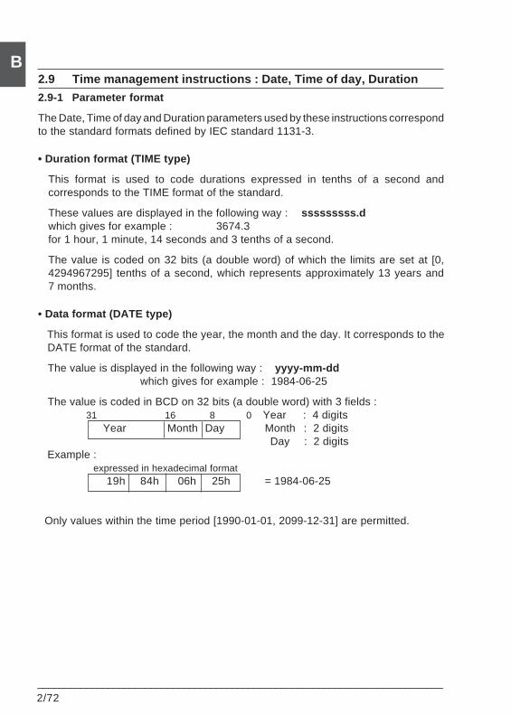
2/72___________________________________________________________________________
B2.9 Time management instructions : Date, Time of day, Duration
2.9-1 Parameter format
The Date, Time of day and Duration parameters used by these instructions correspondto the standard formats defined by IEC standard 1131-3.
• Duration format (TIME type)
This format is used to code durations expressed in tenths of a second andcorresponds to the TIME format of the standard.
These values are displayed in the following way : sssssssss.dwhich gives for example : 3674.3for 1 hour, 1 minute, 14 seconds and 3 tenths of a second.
The value is coded on 32 bits (a double word) of which the limits are set at [0,4294967295] tenths of a second, which represents approximately 13 years and7 months.
• Data format (DATE type)
This format is used to code the year, the month and the day. It corresponds to the DATE format of the standard.
The value is displayed in the following way : yyyy-mm-ddwhich gives for example : 1984-06-25
The value is coded in BCD on 32 bits (a double word) with 3 fields : 31 16 8 0 Year : 4 digits
Year Month Day Month : 2 digits Day : 2 digits Example : expressed in hexadecimal format
19h 84h 06h 25h = 1984-06-25
Only values within the time period [1990-01-01, 2099-12-31] are permitted.
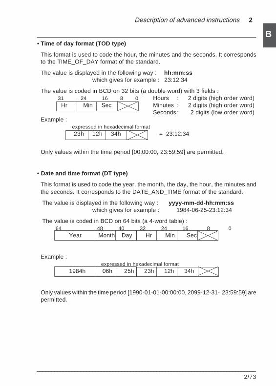
Description of advanced instructions 2
___________________________________________________________________________2/73
B• Time of day format (TOD type)
This format is used to code the hour, the minutes and the seconds. It correspondsto the TIME_OF_DAY format of the standard.
The value is displayed in the following way : hh:mm:sswhich gives for example : 23:12:34
The value is coded in BCD on 32 bits (a double word) with 3 fields : 31 24 16 8 0 Hours : 2 digits (high order word)
Hr Min Sec Minutes : 2 digits (high order word)Seconds : 2 digits (low order word)
Example : expressed in hexadecimal format
23h 12h 34h = 23:12:34
Only values within the time period [00:00:00, 23:59:59] are permitted.
• Date and time format (DT type)
This format is used to code the year, the month, the day, the hour, the minutes andthe seconds. It corresponds to the DATE_AND_TIME format of the standard.
The value is displayed in the following way : yyyy-mm-dd-hh:mm:sswhich gives for example : 1984-06-25-23:12:34
The value is coded in BCD on 64 bits (a 4-word table) :64 48 40 32 24 16 8 0 Year Month Day Hr Min Sec
Example : expressed in hexadecimal format
1984h 06h 25h 23h 12h 34h
Only values within the time period [1990-01-01-00:00:00, 2099-12-31- 23:59:59] arepermitted.
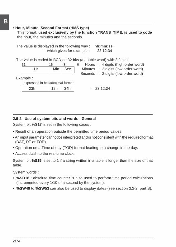
2/74___________________________________________________________________________
B• Hour, Minute, Second Format (HMS type) This format, used exclusively by the function TRANS_TIME, is used to code the hour, the minutes and the seconds.
The value is displayed in the following way : hh:mm:ss which gives for example : 23:12:34
The value is coded in BCD on 32 bits (a double word) with 3 fields : 31 16 8 0 Hours : 4 digits (high order word)
Hr Min Sec Minutes : 2 digits (low order word)Seconds : 2 digits (low order word)
Example : expressed in hexadecimal format
23h 12h 34h = 23:12:34
2.9-2 Use of system bits and words - General
System bit %S17 is set in the following cases :
• Result of an operation outside the permitted time period values.
• An input parameter cannot be interpreted and is not consistent with the required format(DAT, DT or TOD).
• Operation on a Time of day (TOD) format leading to a change in the day.
• Access clash to the real-time clock.
System bit %S15 is set to 1 if a string written in a table is longer than the size of thattable.
System words :
• %SD18 : absolute time counter is also used to perform time period calculations(incremented every 1/10 of a second by the system).
• %SW49 to %SW53 can also be used to display dates (see section 3.2-2, part B).
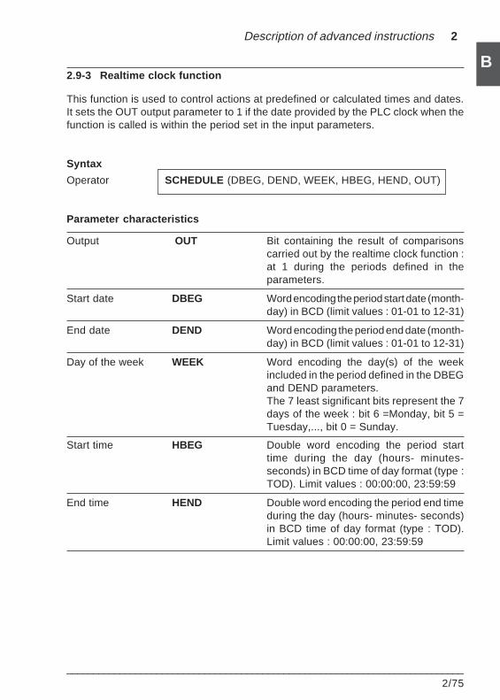
Description of advanced instructions 2
___________________________________________________________________________2/75
B2.9-3 Realtime clock function
This function is used to control actions at predefined or calculated times and dates.It sets the OUT output parameter to 1 if the date provided by the PLC clock when thefunction is called is within the period set in the input parameters.
Syntax
Operator SCHEDULE (DBEG, DEND, WEEK, HBEG, HEND, OUT)
Parameter characteristics
Output OUT Bit containing the result of comparisonscarried out by the realtime clock function :at 1 during the periods defined in theparameters.
Start date DBEG Word encoding the period start date (month-day) in BCD (limit values : 01-01 to 12-31)
End date DEND Word encoding the period end date (month-day) in BCD (limit values : 01-01 to 12-31)
Day of the week WEEK Word encoding the day(s) of the weekincluded in the period defined in the DBEGand DEND parameters.The 7 least significant bits represent the 7days of the week : bit 6 =Monday, bit 5 =Tuesday,..., bit 0 = Sunday.
Start time HBEG Double word encoding the period starttime during the day (hours- minutes-seconds) in BCD time of day format (type :TOD). Limit values : 00:00:00, 23:59:59
End time HEND Double word encoding the period end timeduring the day (hours- minutes- seconds)in BCD time of day format (type : TOD).Limit values : 00:00:00, 23:59:59
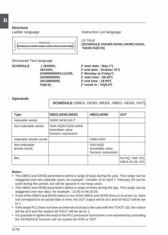
2/76___________________________________________________________________________
BStructureLadder language Instruction List language
LD TRUE[SCHEDULE (%KW0,%KW1,%KW2,%KD3, %KD5,%Q0.0)]
Structured Text languageSCHEDULE ( 16#0501, (* start date : May 1*)
16#1031, (* end date : October 31*)2#0000000001111100, (* Monday to Friday*)16#08300000, (* start time : 08:30*)16#18000000, (* end time : 18:00*)%Q0.0) ; (* result in : %Q0.0*)
OperandsSCHEDULE (DBEG, DEND, WEEK, HBEG, HEND, OUT)
Type DBEG,DEND,WEEK HBEG,HEND OUT
Indexable words %MW,%KW,%Xi.T
Non-indexable words %IW,%QW,%SW,%NWImmediate valueNumeric expression
Indexable double words %MD,%KD
Non-indexable %ID,%QDdouble words Immediate value
Numeric expression
Bits %I,%Q, %M, %S,%BLK,%•:Xk, %X
Notes :• The DBEG and DEND parameters define a range of days during the year. This range can be
staggered over two calendar years, for example : October 10 to April 7. February 29 can beused during this period, but will be ignored in non-leap years.
• The HBEG and HEND parameters define a range of times during the day. This range can bestaggered over two days, for example : 22:00 to 06:10:20.
• If one of the DBEG and DEND dates or one of the HBEG and HEND times is incorrect, ie. doesnot correspond to an actual date or time, the OUT output will be at 0 and bit %S17 will be setto 1.
• If the target PLC does not have an internal clock (as is the case with the TSX37-10), the outputwill be at 0 and the system bit %S17 will be set to 1.
• It is possible to lighten the load on the PLC processor if precision is not important by controllingthe SCHEDULE function call via system bit %S6 or %S7.
SCHEDULE (%KW0,%KW1,%KW2,%KD3,%KD5,%M0)
OPERATE
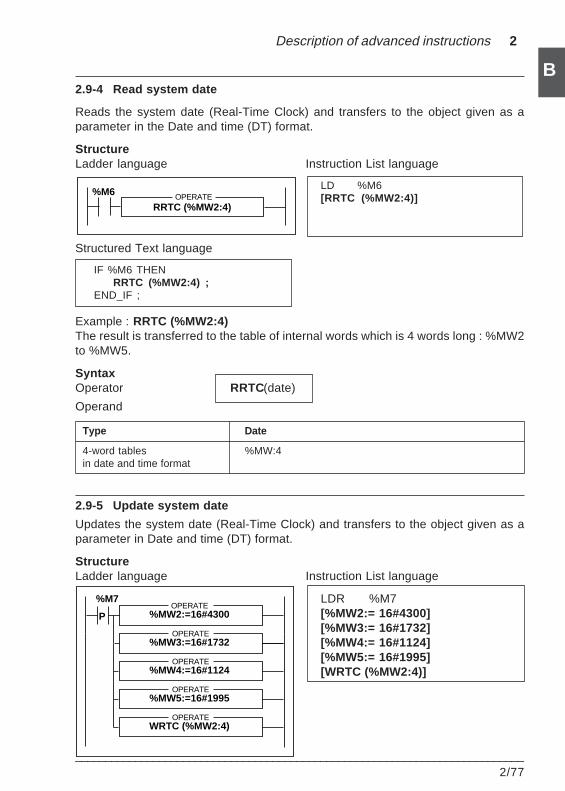
Description of advanced instructions 2
___________________________________________________________________________2/77
B2.9-4 Read system date
Reads the system date (Real-Time Clock) and transfers to the object given as aparameter in the Date and time (DT) format.
StructureLadder language Instruction List language
LD %M6[RRTC (%MW2:4)]
Structured Text language
IF %M6 THENRRTC (%MW2:4) ;
END_IF ;
Example : RRTC (%MW2:4)The result is transferred to the table of internal words which is 4 words long : %MW2to %MW5.
SyntaxOperator RRTC(date)
Operand
Type Date
4-word tables %MW:4in date and time format
2.9-5 Update system date
Updates the system date (Real-Time Clock) and transfers to the object given as aparameter in Date and time (DT) format.
StructureLadder language Instruction List language
LDR %M7[%MW2:= 16#4300][%MW3:= 16#1732][%MW4:= 16#1124][%MW5:= 16#1995][WRTC (%MW2:4)]
RRTC (%MW2:4)OPERATE%M6
%M7
%MW2:=16#4300OPERATE
%MW3:=16#1732
%MW4:=16#1124
%MW5:=16#1995
P
OPERATE
OPERATE
OPERATE
WRTC (%MW2:4)OPERATE
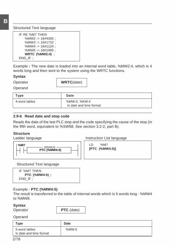
2/78___________________________________________________________________________
BStructured Text language
IF RE %M7 THEN%MW2 := 16#4300 ;%MW3 := 16#1732 ;%MW4 := 16#1124 ;%MW5 := 16#1995 ;WRTC (%MW2:4) ;
END_IF ;
Example : The new date is loaded into an internal word table, %MW2:4, which is 4words long and then sent to the system using the WRTC functions.
Syntax
Operator WRTC(date)
Operand
Type Date
4-word tables %MW:4, %KW:4 in date and time format
2.9-6 Read date and stop code
Reads the date of the last PLC stop and the code specifying the cause of the stop (inthe fifth word, equivalent to %SW58. See section 3.2-2, part B).
StructureLadder language Instruction List language
LD %M7[PTC (%MW4:5)]
Structured Text language
IF %M7 THENPTC (%MW4:5) ;
END_IF ;
Example : PTC (%MW4:5)The result is transferred to the table of internal words which is 5 words long : %MW4to %MW8.
SyntaxOperator PTC (date)
Operand
Type Date
5-word tables %MW:5in date and time format
PTC (%MW4:5)OPERATE
%M7
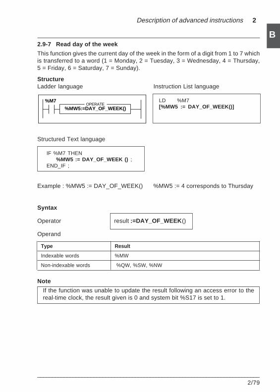
Description of advanced instructions 2
___________________________________________________________________________2/79
B2.9-7 Read day of the week
This function gives the current day of the week in the form of a digit from 1 to 7 whichis transferred to a word (1 = Monday, 2 = Tuesday, 3 = Wednesday, 4 = Thursday,5 = Friday, 6 = Saturday, 7 = Sunday).
StructureLadder language Instruction List language
LD %M7[%MW5 := DAY_OF_WEEK()]
Structured Text language
IF %M7 THEN%MW5 := DAY_OF_WEEK () ;
END_IF ;
Example : %MW5 := DAY_OF_WEEK() %MW5 := 4 corresponds to Thursday
Syntax
Operator result :=DAY_OF_WEEK ()
Operand
Type Result
Indexable words %MW
Non-indexable words %QW, %SW, %NW
Note
If the function was unable to update the result following an access error to thereal-time clock, the result given is 0 and system bit %S17 is set to 1.
%MW5:=DAY_OF_WEEK()OPERATE
%M7
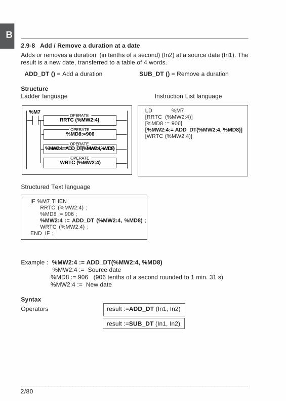
2/80___________________________________________________________________________
B2.9-8 Add / Remove a duration at a date
Adds or removes a duration (in tenths of a second) (In2) at a source date (In1). Theresult is a new date, transferred to a table of 4 words.
ADD_DT () = Add a duration SUB_DT () = Remove a duration
StructureLadder language Instruction List language
LD %M7[RRTC (%MW2:4)][%MD8 := 906][%MW2:4:= ADD_DT(%MW2:4, %MD8)][WRTC (%MW2:4)]
Structured Text language
IF %M7 THENRRTC (%MW2:4) ;%MD8 := 906 ;%MW2:4 := ADD_DT (%MW2:4, %MD8) ;WRTC (%MW2:4) ;
END_IF ;
Example : %MW2:4 := ADD_DT(%MW2:4, %MD8) %MW2:4 := Source date
%MD8 := 906 (906 tenths of a second rounded to 1 min. 31 s) %MW2:4 := New date
Syntax
Operators result :=ADD_DT (In1, In2)
result :=SUB_DT (In1, In2)
%M7
RRTC (%MW2:4)OPERATE
%MD8:=906OPERATE
%MW2:4:=ADD_DT(%MW2:4,%MD8)OPERATE
WRTC (%MW2:4)OPERATE
Description of advanced instructions 2
___________________________________________________________________________2/81
BOperands
Type Result In1 (initial date) In2 (time period)
Table of four words in %MB:4 %MW4:4, %KW:4the date and time format
Indexable double words %MD,%KD
Non-indexable double %ID,%QDwords Immediate value
Numeric expr.
Notes :
• The "duration" parameter (expressed in 1/10 of a second) will be rounded up or down so thatthe date and time can be increased or decreased (precision to within one second).
- sssssssss.0 to sssssssss.4 rounded to sssssssss.0- sssssssss.5 to sssssssss.9 rounded to sssssssss.0 + 1.0
• Provision must be made in the application to handle leap years.
• If the result of the operation is outside the permitted time period values, system bit %S17 is setto 1 and the value of the result equals the minimum limit (for SUB_DT) or remains blocked atthe maximum (for ADD_DT).
• If the "source date" input parameter cannot be interpreted and is not consistent with the DT(DATE_AND_TIME) format, system bit %S17 is set to 1 and the value of the result is0001-01-01-000:00:00.
2.9-9 Add / Remove a duration at a time of day
Adds or removes a time period at a time of day. The result is a new time of day whichis transferred to a double word.
ADD_TOD () = Add a duration SUB_TOD () = Remove a duration
StructureLadder language Instruction List language
LD %M7[%MD8 := 906][%MD2 := ADD_TOD (%MD2, %MD8)]
%M7
%MD8:= 906OPERATE
%MD2:=ADD_TOD(%MD2,%MD8)OPERATE
2/82___________________________________________________________________________
BStructured Text language
IF %M7 THEN%MD8 := 906 ;%MD2 := ADD_TOD (%MD2, %MD8) ;
END_IF ;
Example : %MD2 := ADD_TOD (%MD2, %MD8)%MD2 := Initial time (eg. 12:30:00)%MD8 := 906 (906 tenths of a second rounded to 1 min. 31 s)%MD2 := New time (eg. 12:31:31)
Syntax
Operators result :=ADD_TOD (In1, In2)
result :=SUB_TOD (In1, In2)
Operands
Type Result In1 (initial time) and In2 (time period)
Indexable double words %MD %MD,%KD
Non-indexable double %QD %ID,%QDwords Immediate value, Numeric expression
result and In1 are in the TOD format and In2 is in the time period format.
Notes :
• The "time period" parameter (expressed in 1/10 of a second) will be rounded up or down sothat the date and time can be increased or decreased (precision to within one second).- sssssssss.0 to sssssssss.4 rounded to sssssssss.0- sssssssss.5 to sssssssss.9 rounded to sssssssss.0 + 1.0
• The day changes if the result of the operation is outside the permitted time period values. Inthis case, system bit %S17 is set to 1 and the value of the result can be interpreted with a modulo24:00:00.
• If the "time of day" input parameter cannot be interpreted in the TOD format, system bit %S17is set to 1 and the result is 00:00:00.
Description of advanced instructions 2
___________________________________________________________________________2/83
B2.9-10 Difference between two dates (no time)
This function is used to calculate the difference in days between two dates. The result,given as an absolute value, is transferred to a double word.
StructureLadder language Instruction List language
LD %M7[%MD10 := DELTA_D (%MD2, %MD4)]
Structured Text language
IF %M7 THEN%MD10 := DELTA_D (%MD2, %MD4) ;
END_IF ;
Example : %MD10 := DELTA_D (%MD2, %MD4) %MD2 := Date number1 (eg. 1994-05-01) %MD4 := Date number2 (eg. 1994-04-05)==> %MD10 = 22464000 (==> difference = 26 days)
Syntax
Operator result :=DELTA_D (Date1,Date2)
Operands
Type Result Date 1 and 2
Indexable double words %MD %MD,%KD
Non-indexable double %QD %ID,%QDwords Immediate value, Numeric expr.
result is in the TIME format and Date 1 and 2 are in the DATE format.
The TIME format is defined to be accurate to within one tenth of a second. The DATEformat is defined to be accurate to within one day. The time difference calculated willtherefore be a multiple of 864000 (= 1day = 24 h x 60 min x 60 s x 10 tenths of a second).
Warning
• Overflow occurs if the result exceeds the maximum value permitted for aduration (TIME). In this case, the result is 0 and system bit %S18 is set to 1.
• If one of the input parameters cannot be interpreted and is not consistent withthe DATE format, system bit %S17 is set to 1 and the result is 0.
%MD10:=DELTA_D(%MD2,%MD4)OPERATE
%M7
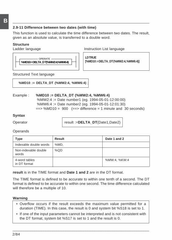
2/84___________________________________________________________________________
B2.9-11 Difference between two dates (with time)
This function is used to calculate the time difference between two dates. The result,given as an absolute value, is transferred to a double word.
StructureLadder language Instruction List language
LD TRUE[%MD10 := DELTA_DT (%MW2:4, %MW6:4)]
Structured Text language
%MD10 := DELTA_DT (%MW2:4, %MW6:4) ;
Example : %MD10 := DELTA_DT (%MW2:4, %MW6:4) %MW2:4 := Date number1 (eg. 1994-05-01-12:00:00) %MW6:4 := Date number2 (eg. 1994-05-01-12:01:30)==> %MD10 = 900 (==> difference = 1 minute and 30 seconds)
Syntax
Operator result :=DELTA_DT (Date1,Date2)
Operands
Type Result Date 1 and 2
Indexable double words %MD,
Non-indexable double %QDwords
4-word tables %MW:4, %KW:4in DT format
result is in the TIME format and Date 1 and 2 are in the DT format.
The TIME format is defined to be accurate to within one tenth of a second. The DTformat is defined to be accurate to within one second. The time difference calculatedwill therefore be a multiple of 10.
Warning
• Overflow occurs if the result exceeds the maximum value permitted for aduration (TIME). In this case, the result is 0 and system bit %S18 is set to 1.
• If one of the input parameters cannot be interpreted and is not consistent withthe DT format, system bit %S17 is set to 1 and the result is 0.
%MD10:= DELTA_D T(%MW2:4,%MW6:4)OPERATE
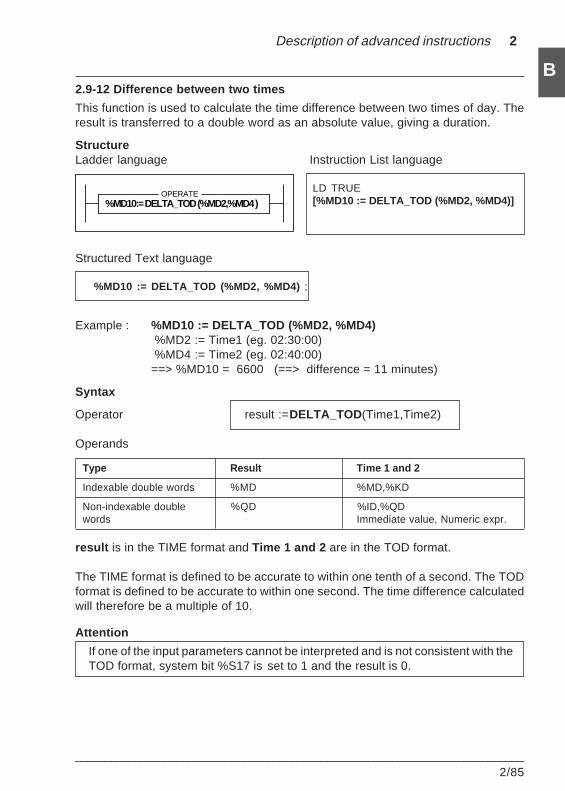
Description of advanced instructions 2
___________________________________________________________________________2/85
B2.9-12 Difference between two times
This function is used to calculate the time difference between two times of day. Theresult is transferred to a double word as an absolute value, giving a duration.
StructureLadder language Instruction List language
LD TRUE[%MD10 := DELTA_TOD (%MD2, %MD4)]
Structured Text language
%MD10 := DELTA_TOD (%MD2, %MD4) ;
Example : %MD10 := DELTA_TOD (%MD2, %MD4) %MD2 := Time1 (eg. 02:30:00) %MD4 := Time2 (eg. 02:40:00)==> %MD10 = 6600 (==> difference = 11 minutes)
Syntax
Operator result :=DELTA_TOD (Time1,Time2)
Operands
Type Result Time 1 and 2
Indexable double words %MD %MD,%KD
Non-indexable double %QD %ID,%QDwords Immediate value, Numeric expr.
result is in the TIME format and Time 1 and 2 are in the TOD format.
The TIME format is defined to be accurate to within one tenth of a second. The TODformat is defined to be accurate to within one second. The time difference calculatedwill therefore be a multiple of 10.
Attention
If one of the input parameters cannot be interpreted and is not consistent with theTOD format, system bit %S17 is set to 1 and the result is 0.
%MD10:= DELTA_TOD (%MD2,%MD4 )OPERATE
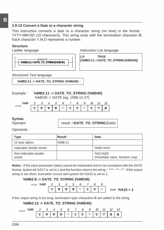
2/86___________________________________________________________________________
B2.9-13 Convert a Date to a character string
This instruction converts a date to a character string (no time) in the format :YYYY-MM-DD (10 characters). This string ends with the termination character Ø.Each character Y,M,D represents a number.
StructureLadder language Instruction List language
LD TRUE[%MB2:11 := DATE_TO_STRING (%MD40)]
Structured Text language
%MB2:11 := DATE_TO_STRING (%MD40) ;
Example : %MB2:11 := DATE_TO_STRING (%MD40) %MD40 := DATE (eg. 1998-12-27)
==>
SyntaxOperator result :=DATE_TO_STRING (Date)
Operands
Type Result Date
11-byte tables %MB:11
Indexable double words %MD,%KD
Non-indexable double %ID,%QDwords Immediate value, Numeric expr.
Notes : If the input parameter (date) cannot be interpreted and is not consistent with the DATEformat, system bit %S17 is set to 1 and the function returns the string : ' **** - ** - ** '. If the outputstring is too short, truncation occurs and system bit %S15 is set to 1.
%MB2:8 := DATE_TO_STRING (%MD40)
==>
If the output string is too long, termination type characters Ø are added to the string.
%MB2:12 := DATE_TO_STRING (%MD40)
==>
'1' '9' '9' '8' '-' '1' '2' '-'
%MB 2 3 4 5 6 7 8 9
==> %S15 = 1
'1' '9' '9' '8' '-' '1' '2' '-' '2' '7'
%MB 2 3 4 5 6 7 8 9 10 11
Ø
12
%MB2:11:= DATE_TO_STRING(%MD40 )OPERATE
'1' '9' '9' '8' '-' '1' '2' '-' '2' '7' Ø
%MB 2 3 4 5 6 7 8 9 10 11 12
Ø
13
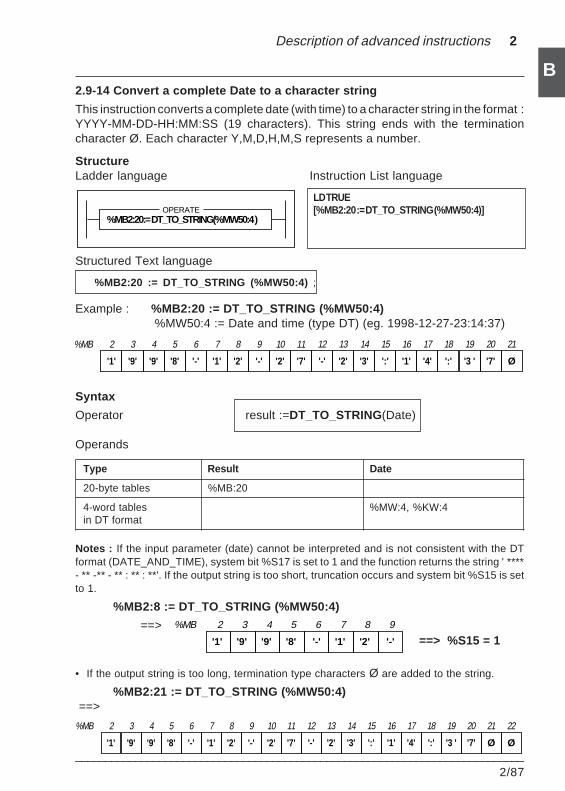
Description of advanced instructions 2
___________________________________________________________________________2/87
B
'1' '9' '9' '8' '-' '1' '2' '-'
%MB 2 3 4 5 6 7 8 9
2.9-14 Convert a complete Date to a character string
This instruction converts a complete date (with time) to a character string in the format :YYYY-MM-DD-HH:MM:SS (19 characters). This string ends with the terminationcharacter Ø. Each character Y,M,D,H,M,S represents a number.
StructureLadder language Instruction List language
LD TRUE[%MB2:20 := DT_TO_STRING (%MW50:4)]
Structured Text language
%MB2:20 := DT_TO_STRING (%MW50:4) ;
Example : %MB2:20 := DT_TO_STRING (%MW50:4) %MW50:4 := Date and time (type DT) (eg. 1998-12-27-23:14:37)
Syntax
Operator result :=DT_TO_STRING(Date)
Operands
Type Result Date
20-byte tables %MB:20
4-word tables %MW:4, %KW:4in DT format
Notes : If the input parameter (date) cannot be interpreted and is not consistent with the DTformat (DATE_AND_TIME), system bit %S17 is set to 1 and the function returns the string ' ****- ** -** - ** : ** : **'. If the output string is too short, truncation occurs and system bit %S15 is setto 1.
%MB2:8 := DT_TO_STRING (%MW50:4)
==>
• If the output string is too long, termination type characters Ø are added to the string.
%MB2:21 := DT_TO_STRING (%MW50:4) ==>
==> %S15 = 1
'1' '9' '9' '8' '-' '1' '2' '-' '2' '7'
%MB 2 3 4 5 6 7 8 9 10 11
'-' '2' '3' ':' '1' '4' ':' '3 '
12 13 14 15 16 17 18 19
'7' Ø
20 21
Ø
22
'1' '9' '9' '8' '-' '1' '2' '-' '2' '7'
%MB 2 3 4 5 6 7 8 9 10 11
'-' '2' '3' ':' '1' '4' ':' '3 '
12 13 14 15 16 17 18 19
'7' Ø
20 21
%MB2:20:= DT_TO_STRING(%MW50:4 )OPERATE
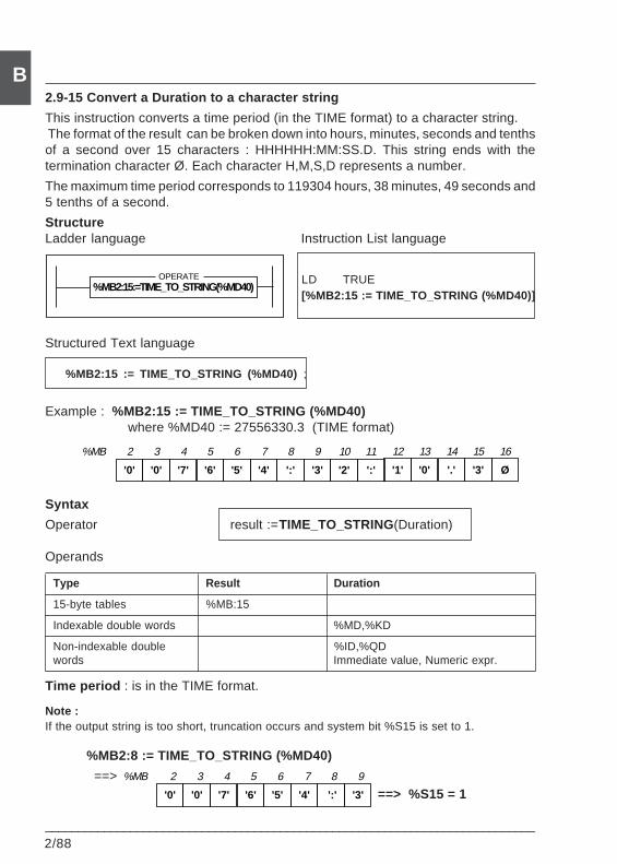
2/88___________________________________________________________________________
B
'0' '0' '7' '6' '5' '4' ':' '3'
%MB 2 3 4 5 6 7 8 9
2.9-15 Convert a Duration to a character string
This instruction converts a time period (in the TIME format) to a character string. The format of the result can be broken down into hours, minutes, seconds and tenthsof a second over 15 characters : HHHHHH:MM:SS.D. This string ends with thetermination character Ø. Each character H,M,S,D represents a number.
The maximum time period corresponds to 119304 hours, 38 minutes, 49 seconds and5 tenths of a second.
StructureLadder language Instruction List language
Structured Text language
%MB2:15 := TIME_TO_STRING (%MD40) ;
Example : %MB2:15 := TIME_TO_STRING (%MD40)where %MD40 := 27556330.3 (TIME format)
Syntax
Operator result :=TIME_TO_STRING(Duration)
Operands
Type Result Duration
15-byte tables %MB:15
Indexable double words %MD,%KD
Non-indexable double %ID,%QDwords Immediate value, Numeric expr.
Time period : is in the TIME format.
Note :If the output string is too short, truncation occurs and system bit %S15 is set to 1.
%MB2:8 := TIME_TO_STRING (%MD40)
==>
LD TRUE[%MB2:15 := TIME_TO_STRING (%MD40)]
==> %S15 = 1
'0' '0' '7' '6' '5' '4' ':' '3' '2' ':'
%MB 2 3 4 5 6 7 8 9 10 11
'1' '0' '.' '3' Ø
12 13 14 15 16
%MB2:15:=TIME_TO_STRING(%MD40)OPERATE
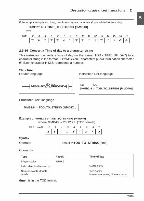
Description of advanced instructions 2
___________________________________________________________________________2/89
BIf the output string is too long, termination type characters Ø are added to the string.
%MB2:16 := TIME_TO_STRING (%MD40) ==>
2.9-16 Convert a Time of day to a character string
This instruction converts a time of day (in the format TOD - TIME_OF_DAY) to acharacter string in the format HH:MM:SS on 8 characters plus a termination characterØ. Each character H,M,S represents a number.
StructureLadder language Instruction List language
Structured Text language
%MB2:9 := TOD_TO_STRING (%MD40) ;
Example : %MB2:9 := TOD_TO_STRING (%MD40)where %MD40 := 23:12:27 (TOD format)
==>
Syntax
Operator result :=TOD_TO_STRING(time)
Operands
Type Result Time of day
9-byte tables %MB:9
Indexable double words %MD,%KD
Non-indexable double %ID,%QDwords Immediate value, Numeric expr.
time : is in the TOD format.
LD TRUE[%MB2:9 := TOD_TO_STRING (%MD40)]
'2' '3' ':' '1' '2' ':' '2' '7'
%MB 2 3 4 5 6 7 8 9
Ø
10
'0' '0' '7' '6' '5' '4' ':' '3' '2' ':'
%MB 2 3 4 5 6 7 8 9 10 11
'1' '0' '.' '3' Ø
12 13 14 15 16
Ø
17
%MB2:9:=TOD_TO_STRING(%MD40)OPERATE
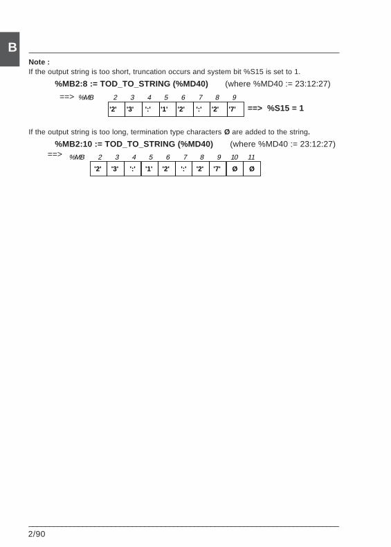
2/90___________________________________________________________________________
B
'2' '3' ':' '1' '2' ':' '2' '7'
%MB 2 3 4 5 6 7 8 9
Ø
10
Ø
11
'2' '3' ':' '1' '2' ':' '2' '7'
%MB 2 3 4 5 6 7 8 9
Note :If the output string is too short, truncation occurs and system bit %S15 is set to 1.
%MB2:8 := TOD_TO_STRING (%MD40) (where %MD40 := 23:12:27)
==> ==> %S15 = 1
If the output string is too long, termination type characters Ø are added to the string.
%MB2:10 := TOD_TO_STRING (%MD40) (where %MD40 := 23:12:27) ==>
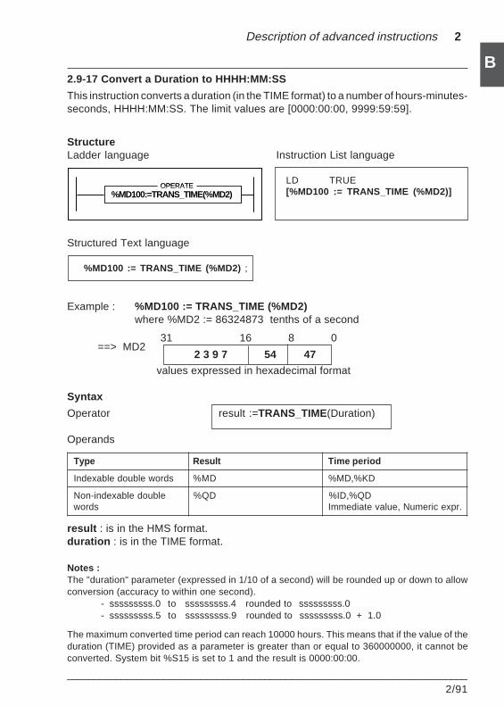
Description of advanced instructions 2
___________________________________________________________________________2/91
B2.9-17 Convert a Duration to HHHH:MM:SS
This instruction converts a duration (in the TIME format) to a number of hours-minutes-seconds, HHHH:MM:SS. The limit values are [0000:00:00, 9999:59:59].
StructureLadder language Instruction List language
LD TRUE[%MD100 := TRANS_TIME (%MD2)]
Structured Text language
%MD100 := TRANS_TIME (%MD2) ;
Example : %MD100 := TRANS_TIME (%MD2)where %MD2 := 86324873 tenths of a second
==> MD2
values expressed in hexadecimal format
Syntax
Operator result :=TRANS_TIME(Duration)
Operands
Type Result Time period
Indexable double words %MD %MD,%KD
Non-indexable double %QD %ID,%QDwords Immediate value, Numeric expr.
result : is in the HMS format.duration : is in the TIME format.
Notes :The "duration" parameter (expressed in 1/10 of a second) will be rounded up or down to allowconversion (accuracy to within one second).
- sssssssss.0 to sssssssss.4 rounded to sssssssss.0- sssssssss.5 to sssssssss.9 rounded to sssssssss.0 + 1.0
The maximum converted time period can reach 10000 hours. This means that if the value of theduration (TIME) provided as a parameter is greater than or equal to 360000000, it cannot beconverted. System bit %S15 is set to 1 and the result is 0000:00:00.
31 16 8 0
2 3 9 7 54 47
%MD100:=TRANS_TIME(%MD2)OPERATE
%MD100:=TRANS_TIME(%MD2)OPERATE
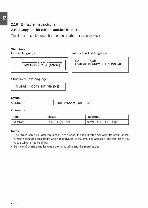
2/92___________________________________________________________________________
B2.10 Bit table instructions
2.10-1 Copy one bit table to another bit table
This function copies one bit table into another bit table bit-wise.
StructureLadder language Instruction List language
LD TRUE[%M10:5 := COPY_BIT (%M20:5)]
Structured Text language
%M10:5 := COPY_BIT (%M20:5) ;
Syntax
Operator result :=COPY_BIT (Tab)
Operands
Type Result Table (tab)
Bit table %M:L, %Q:L, %I:L %M:L, %Q:L, %I:L, %Xi:L
Notes :• The tables can be of different sizes. In this case, the result table contains the result of the
function executed on a length which is equivalent to the smallest table size, and the rest of theresult table is not modified.
• Beware of overlapping between the input table and the result table.
%M10:5:=COPY_BIT(%M20:5)OPERATE
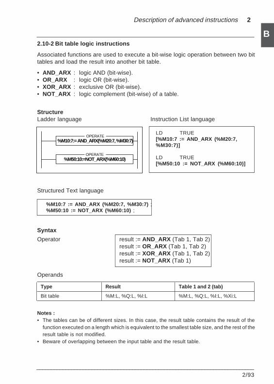
Description of advanced instructions 2
___________________________________________________________________________2/93
B2.10-2 Bit table logic instructions
Associated functions are used to execute a bit-wise logic operation between two bittables and load the result into another bit table.
• AND_ARX : logic AND (bit-wise).• OR_ARX : logic OR (bit-wise).• XOR_ARX : exclusive OR (bit-wise).• NOT_ARX : logic complement (bit-wise) of a table.
StructureLadder language Instruction List language
LD TRUE[%M10:7 := AND_ARX (%M20:7,%M30:7)]
LD TRUE[%M50:10 := NOT_ARX (%M60:10)]
Structured Text language
%M10:7 := AND_ARX (%M20:7, %M30:7) ;%M50:10 := NOT_ARX (%M60:10) ;
Syntax
Operator result := AND_ARX (Tab 1, Tab 2)result := OR_ARX (Tab 1, Tab 2)result := XOR_ARX (Tab 1, Tab 2)result := NOT_ARX (Tab 1)
Operands
Type Result Table 1 and 2 (tab)
Bit table %M:L, %Q:L, %I:L %M:L, %Q:L, %I:L, %Xi:L
Notes :• The tables can be of different sizes. In this case, the result table contains the result of the
function executed on a length which is equivalent to the smallest table size, and the rest of theresult table is not modified.
• Beware of overlapping between the input table and the result table.
%M10:7:= AND_ARX(%M20:7, %M30:7)OPERATE
%M50:10:=NOT_ARX(%M60:10)OPERATE
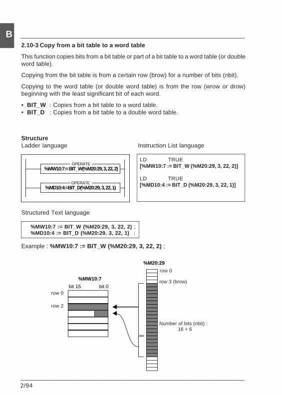
2/94___________________________________________________________________________
B2.10-3 Copy from a bit table to a word table
This function copies bits from a bit table or part of a bit table to a word table (or doubleword table).
Copying from the bit table is from a certain row (brow) for a number of bits (nbit).
Copying to the word table (or double word table) is from the row (wrow or drow)beginning with the least significant bit of each word.
• BIT_W : Copies from a bit table to a word table.• BIT_D : Copies from a bit table to a double word table.
StructureLadder language Instruction List language
LD TRUE[%MW10:7 := BIT_W (%M20:29, 3, 22, 2)]
LD TRUE[%MD10:4 := BIT_D (%M20:29, 3, 22, 1)]
Structured Text language
%MW10:7 := BIT_W (%M20:29, 3, 22, 2) ;%MD10:4 := BIT_D (%M20:29, 3, 22, 1) ;
Example : %MW10:7 := BIT_W (%M20:29, 3, 22, 2) ;
%MW10:7:= BIT_W(%M20:29, 3, 22, 2)OPERATE
%MD10:4:=BIT_D(%M20:29, 3, 22, 1)OPERATE
bit 15 bit 0
%MW10:7
%M20:29
row 0
row 2
row 0
row 3 (brow)
Number of bits (nbit) :16 + 6
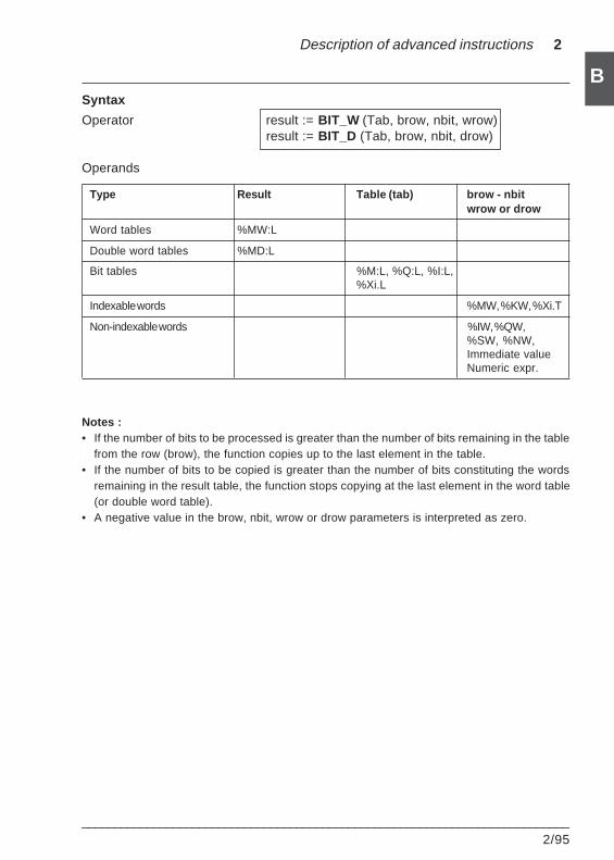
Description of advanced instructions 2
___________________________________________________________________________2/95
BSyntax
Operator result := BIT_W (Tab, brow, nbit, wrow)result := BIT_D (Tab, brow, nbit, drow)
Operands
Type Result Table (tab) brow - nbitwrow or drow
Word tables %MW:L
Double word tables %MD:L
Bit tables %M:L, %Q:L, %I:L,%Xi.L
Indexable words %MW, %KW, %Xi.T
Non-indexable words %IW, %QW,%SW, %NW,Immediate valueNumeric expr.
Notes :• If the number of bits to be processed is greater than the number of bits remaining in the table
from the row (brow), the function copies up to the last element in the table.• If the number of bits to be copied is greater than the number of bits constituting the words
remaining in the result table, the function stops copying at the last element in the word table(or double word table).
• A negative value in the brow, nbit, wrow or drow parameters is interpreted as zero.
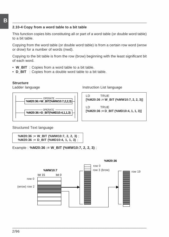
2/96___________________________________________________________________________
B2.10-4 Copy from a word table to a bit table
This function copies bits constituting all or part of a word table (or double word table)to a bit table.
Copying from the word table (or double word table) is from a certain row word (wrowor drow) for a number of words (nwd).
Copying to the bit table is from the row (brow) beginning with the least significant bitof each word.
• W_BIT : Copies from a word table to a bit table.• D_BIT : Copies from a double word table to a bit table.
StructureLadder language Instruction List language
LD TRUE[%M20:36 := W_BIT (%MW10:7, 2, 2, 3)]
LD TRUE[%M20:36 := D_BIT (%MD10:4, 1, 1, 3)]
Structured Text language
%M20:36 := W_BIT (%MW10:7, 2, 2, 3) ;%M20:36 := D_BIT (%MD10:4, 1, 1, 3) ;
Example : %M20:36 := W_BIT (%MW10:7, 2, 2, 3) ;
%M20:36:=W_BIT(%MW10:7,2,2,3)OPERATE
%M20:36:=D_BIT(%MD10:4,1,1,3)OPERATE
bit 15 bit 0
%MW10:7
%M20:36
row 0
(wrow) row 2
row 0row 3 (brow) row 19
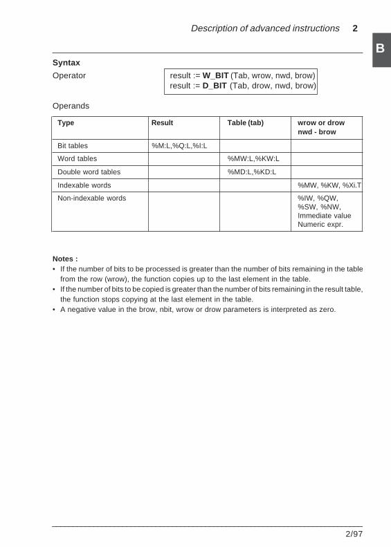
Description of advanced instructions 2
___________________________________________________________________________2/97
BSyntax
Operator result := W_BIT (Tab, wrow, nwd, brow)result := D_BIT (Tab, drow, nwd, brow)
Operands
Type Result Table (tab) wrow or drownwd - brow
Bit tables %M:L,%Q:L,%I:L
Word tables %MW:L,%KW:L
Double word tables %MD:L,%KD:L
Indexable words %MW, %KW, %Xi.T
Non-indexable words %IW, %QW,%SW, %NW,Immediate valueNumeric expr.
Notes :• If the number of bits to be processed is greater than the number of bits remaining in the table
from the row (wrow), the function copies up to the last element in the table.• If the number of bits to be copied is greater than the number of bits remaining in the result table,
the function stops copying at the last element in the table.• A negative value in the brow, nbit, wrow or drow parameters is interpreted as zero.
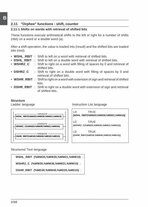
2/98___________________________________________________________________________
B2.11 "Orphee" functions : shift, counter
2.11-1 Shifts on words with retrieval of shifted bits
These functions execute arithmetical shifts to the left or right for a number of shifts(nbit) on a word or a double word (a).
After a shift operation, the value is loaded into (result) and the shifted bits are loadedinto (rest).
• WSHL_RBIT : Shift to left on a word with retrieval of shifted bits.• DSHL_RBIT : Shift to left on a double word with retrieval of shifted bits.• WSHRZ_C : Shift to right on a word with filling of spaces by 0 and retrieval of
shifted bits.• DSHRZ_C : Shift to right on a double word with filling of spaces by 0 and
retrieval of shifted bits.• WSHR_RBIT : Shift to right on a word with extension of sign and retrieval of shifted
bits.• DSHR_RBIT : Shift to right on a double word with extension of sign and retrieval
of shifted bits.
StructureLadder language Instruction List language
LD TRUE[WSHL_RBIT(%MW20,%MW30,%MW21,%MW10)]
LD TRUE[WSHRZ_C(%MW20,%MW30,%MW21,%MW10)]
LD TRUE[DSHR_RBIT(%MD30,%MW40,%MD20,%MD10)]
Structured Text language
WSHL_RBIT (%MW20,%MW30,%MW21,%MW10) ;
WSHRZ_C (%MW20,%MW30,%MW21,%MW10) ;
DSHR_RBIT (%MD30,%MW40,%MD20,%MD10) ;
WSHL_RBIT(%MW20,%MW30,%MW21,%MW10)OPERATE
WSHRZ_C(%MW20,%MW30,%MW21,%MW10)OPERATE
DSHR_RBIT(%MD30,%MW40,%MD20,%MD10)OPERATE
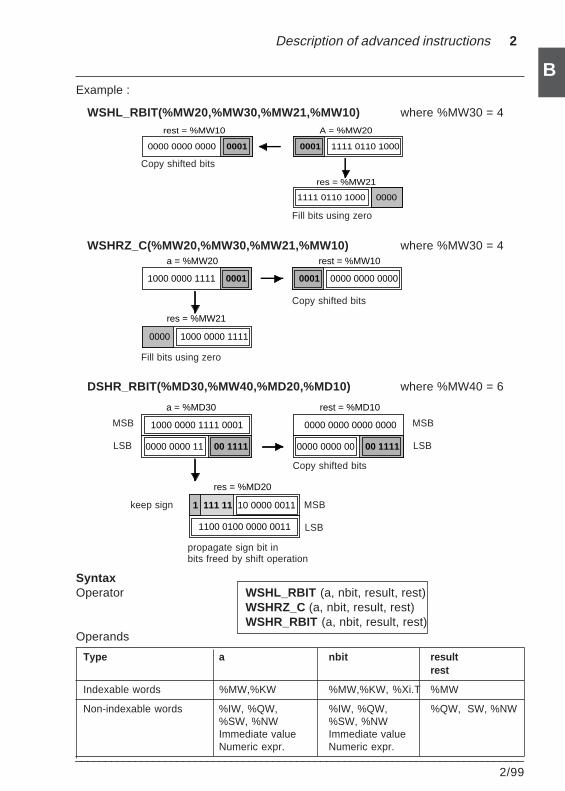
Description of advanced instructions 2
___________________________________________________________________________2/99
BExample :
WSHL_RBIT(%MW20,%MW30,%MW21,%MW10) where %MW30 = 4
WSHRZ_C(%MW20,%MW30,%MW21,%MW10) where %MW30 = 4
DSHR_RBIT(%MD30,%MW40,%MD20,%MD10) where %MW40 = 6
SyntaxOperator WSHL_RBIT (a, nbit, result, rest)
WSHRZ_C (a, nbit, result, rest)WSHR_RBIT (a, nbit, result, rest)
Operands
Type a nbit resultrest
Indexable words %MW,%KW %MW,%KW, %Xi.T %MW
Non-indexable words %IW, %QW, %IW, %QW, %QW, SW, %NW%SW, %NW %SW, %NWImmediate value Immediate valueNumeric expr. Numeric expr.
1000 0000 1111 0001 0001 0000 0000 0000
a = %MW20 rest = %MW10
0000 1000 0000 1111
res = %MW21
1111 0110 1000 0000
0000 0000 0000 0001 0001 1111 0110 1000
rest = %MW10 A = %MW20
res = %MW21
Copy shifted bits
Fill bits using zero
Copy shifted bits
Fill bits using zero
0000 0000 11 00 1111
1000 0000 1111 0001 0000 0000 0000 0000
a = %MD30 rest = %MD10
0000 0000 00 00 1111
res = %MD20
1100 0100 0000 0011
1 111 11 10 0000 0011 MSB
LSB
Copy shifted bits
propagate sign bit inbits freed by shift operation
keep sign
MSB
LSB
MSB
LSB
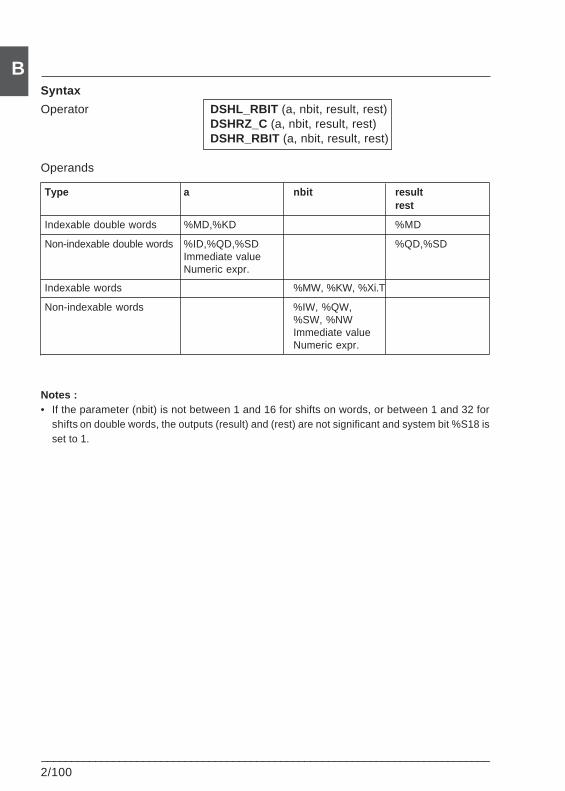
2/100___________________________________________________________________________
BSyntax
Operator DSHL_RBIT (a, nbit, result, rest)DSHRZ_C (a, nbit, result, rest)DSHR_RBIT (a, nbit, result, rest)
Operands
Type a nbit resultrest
Indexable double words %MD,%KD %MD
Non-indexable double words %ID,%QD,%SD %QD,%SDImmediate valueNumeric expr.
Indexable words %MW, %KW, %Xi.T
Non-indexable words %IW, %QW,%SW, %NWImmediate valueNumeric expr.
Notes :• If the parameter (nbit) is not between 1 and 16 for shifts on words, or between 1 and 32 for
shifts on double words, the outputs (result) and (rest) are not significant and system bit %S18 isset to 1.
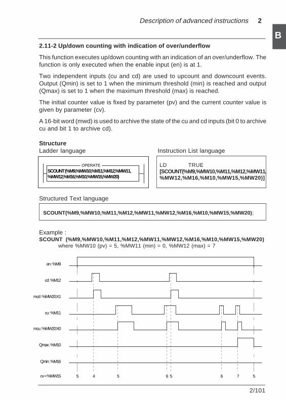
Description of advanced instructions 2
___________________________________________________________________________2/101
B2.11-2 Up/down counting with indication of over/underflow
This function executes up/down counting with an indication of an over/underflow. Thefunction is only executed when the enable input (en) is at 1.
Two independent inputs (cu and cd) are used to upcount and downcount events.Output (Qmin) is set to 1 when the minimum threshold (min) is reached and output(Qmax) is set to 1 when the maximum threshold (max) is reached.
The initial counter value is fixed by parameter (pv) and the current counter value isgiven by parameter (cv).
A 16-bit word (mwd) is used to archive the state of the cu and cd inputs (bit 0 to archivecu and bit 1 to archive cd).
StructureLadder language Instruction List language
LD TRUE[SCOUNT(%M9,%MW10,%M11,%M12,%MW11,%MW12,%M16,%M10,%MW15,%MW20)]
Structured Text language
SCOUNT(%M9,%MW10,%M11,%M12,%MW11,%MW12,%M16,%M10,%MW15,%MW20) ;
Example :SCOUNT (%M9,%MW10,%M11,%M12,%MW11,%MW12,%M16,%M10,%MW15,%MW20)
where %MW10 (pv) = 5, %MW11 (min) = 0, %MW12 (max) = 7
5 4 5 6 5 6 7 5
en : %M9
cd : %M12
mcd : %MW20:X1
cu : %M11
mcu : %MW20:X0
Qmax : %M10
Qmin : %M16
cv = %MW15
SCOUNT (%M9,%MW10,%M11,%M12,%MW11,%MW12,%M16,%M10,%MW15,%MW20)
OPERATE
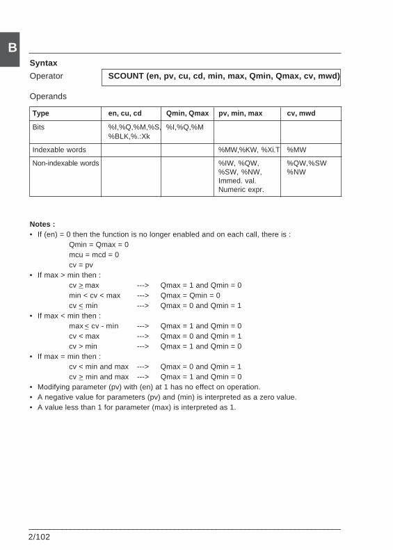
2/102___________________________________________________________________________
BSyntax
Operator SCOUNT (en, pv, cu, cd, min, max, Qmin, Qmax, cv, mwd)
Operands
Type en, cu, cd Qmin, Qmax pv, min, max cv, mwd
Bits %I,%Q,%M,%S, %I,%Q,%M%BLK,%.:Xk
Indexable words %MW,%KW, %Xi.T %MW
Non-indexable words %IW, %QW, %QW,%SW%SW, %NW, %NWImmed. val.Numeric expr.
Notes :• If (en) = 0 then the function is no longer enabled and on each call, there is :
Qmin = Qmax = 0mcu = mcd = 0cv = pv
• If max > min then :cv > max ---> Qmax = 1 and Qmin = 0min < cv < max ---> Qmax = Qmin = 0cv < min ---> Qmax = 0 and Qmin = 1
• If max < min then :max < cv - min ---> Qmax = 1 and Qmin = 0cv < max ---> Qmax = 0 and Qmin = 1cv > min ---> Qmax = 1 and Qmin = 0
• If max = min then :cv < min and max ---> Qmax = 0 and Qmin = 1cv > min and max ---> Qmax = 1 and Qmin = 0
• Modifying parameter (pv) with (en) at 1 has no effect on operation.• A negative value for parameters (pv) and (min) is interpreted as a zero value.• A value less than 1 for parameter (max) is interpreted as 1.
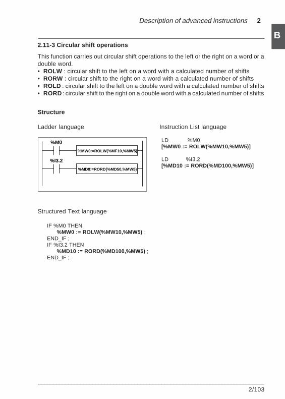
Description of advanced instructions 2
___________________________________________________________________________2/103
B2.11-3 Circular shift operations
This function carries out circular shift operations to the left or the right on a word or adouble word.• ROLW : circular shift to the left on a word with a calculated number of shifts• RORW : circular shift to the right on a word with a calculated number of shifts• ROLD : circular shift to the left on a double word with a calculated number of shifts• RORD : circular shift to the right on a double word with a calculated number of shifts
Structure
Ladder language Instruction List language
LD %M0[%MW0 := ROLW(%MW10,%MW5)]
LD %I3.2[%MD10 := RORD(%MD100,%MW5)]
Structured Text language
IF %M0 THEN%MW0 := ROLW(%MW10,%MW5) ;
END_IF ;IF %I3.2 THEN
%MD10 := RORD(%MD100,%MW5) ;END_IF ;
%I3.2
%MW0:=ROLW(%MF10,%MW5)
%MD8:=RORD(%MD50,%MW5)
%M0
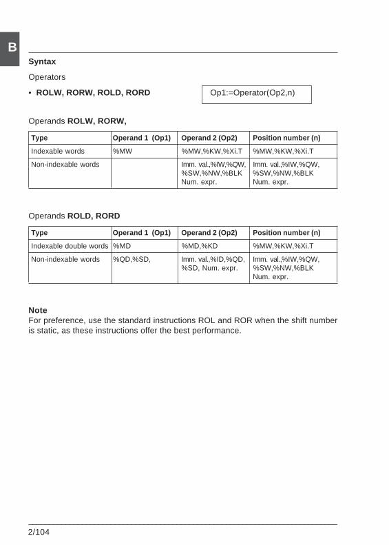
2/104___________________________________________________________________________
BSyntax
Operators
• ROLW, RORW, ROLD, RORD Op1:=Operator(Op2,n)
Operands ROLW, RORW,
Type Operand 1 (Op1) Operand 2 (Op2) Position number (n)
Indexable words %MW %MW,%KW,%Xi.T %MW,%KW,%Xi.T
Non-indexable words Imm. val.,%IW,%QW, Imm. val.,%IW,%QW,%SW,%NW,%BLK %SW,%NW,%BLKNum. expr. Num. expr.
Operands ROLD, RORD
Type Operand 1 (Op1) Operand 2 (Op2) Position number (n)
Indexable double words %MD %MD,%KD %MW,%KW,%Xi.T
Non-indexable words %QD,%SD, Imm. val.,%ID,%QD, Imm. val.,%IW,%QW,%SD, Num. expr. %SW,%NW,%BLK
Num. expr.
NoteFor preference, use the standard instructions ROL and ROR when the shift numberis static, as these instructions offer the best performance.
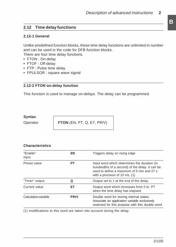
Description of advanced instructions 2
___________________________________________________________________________2/105
B2.12 Time delay functions
2.12-1 General
Unlike predefined function blocks, these time delay functions are unlimited in numberand can be used in the code for DFB function blocks.There are four time delay functions.• FTON : On-delay• FTOF : Off-delay• FTP : Pulse time delay• FPULSOR : square wave signal
2.12-2 FTON on-delay function
This function is used to manage on-delays. The delay can be programmed.
Syntax
Operator FTON (EN, PT, Q, ET, PRIV)
Characteristics
"Enable" EN Triggers delay on rising edgeinput
Preset value PT Input word which determines the duration (inhundredths of a second) of the delay. It can beused to define a maximum of 5 min and 27 swith a precision of 10 ms. (1)
"Timer" output Q Output set to 1 at the end of the delay.
Current value ET Output word which increases from 0 to PTwhen the time delay has elapsed.
Calculation variable PRIV Double word for storing internal states.Associate an application variable exclusivelyreserved for this purpose with this double word
(1) modifications to this word are taken into account during the delay.
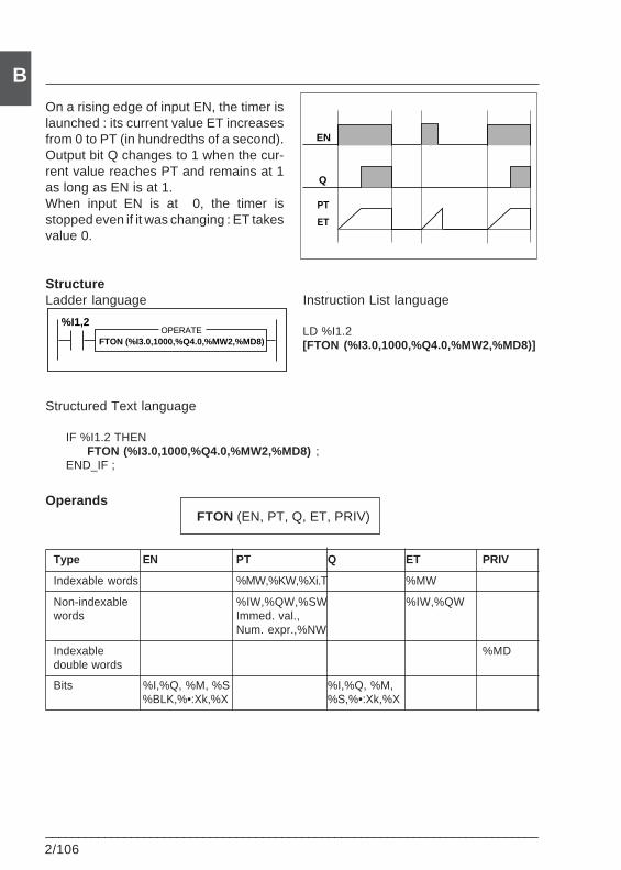
2/106___________________________________________________________________________
BOn a rising edge of input EN, the timer islaunched : its current value ET increasesfrom 0 to PT (in hundredths of a second).Output bit Q changes to 1 when the cur-rent value reaches PT and remains at 1as long as EN is at 1.When input EN is at 0, the timer isstopped even if it was changing : ET takesvalue 0.
StructureLadder language Instruction List language
LD %I1.2[FTON (%I3.0,1000,%Q4.0,%MW2,%MD8)]
Structured Text language
IF %I1.2 THENFTON (%I3.0,1000,%Q4.0,%MW2,%MD8) ;
END_IF ;
OperandsFTON (EN, PT, Q, ET, PRIV)
Type EN PT Q ET PRIV
Indexable words %MW,%KW,%Xi.T %MW
Non-indexable %IW,%QW,%SW %IW,%QWwords Immed. val.,
Num. expr.,%NW
Indexable %MDdouble words
Bits %I,%Q, %M, %S %I,%Q, %M,%BLK,%•:Xk,%X %S,%•:Xk,%X
EN
Q
ET
PT
FTON (%I3.0,1000,%Q4.0,%MW2,%MD8)OPERATE
%I1,2
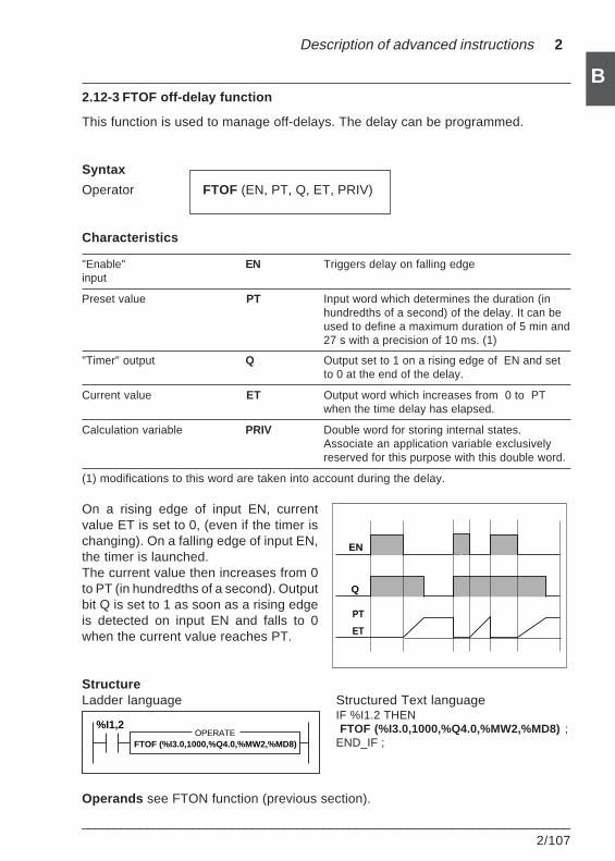
Description of advanced instructions 2
___________________________________________________________________________2/107
B2.12-3 FTOF off-delay function
This function is used to manage off-delays. The delay can be programmed.
Syntax
Operator FTOF (EN, PT, Q, ET, PRIV)
Characteristics
"Enable" EN Triggers delay on falling edgeinput
Preset value PT Input word which determines the duration (inhundredths of a second) of the delay. It can beused to define a maximum duration of 5 min and27 s with a precision of 10 ms. (1)
"Timer" output Q Output set to 1 on a rising edge of EN and setto 0 at the end of the delay.
Current value ET Output word which increases from 0 to PTwhen the time delay has elapsed.
Calculation variable PRIV Double word for storing internal states.Associate an application variable exclusivelyreserved for this purpose with this double word.
(1) modifications to this word are taken into account during the delay.
On a rising edge of input EN, currentvalue ET is set to 0, (even if the timer ischanging). On a falling edge of input EN,the timer is launched.The current value then increases from 0to PT (in hundredths of a second). Outputbit Q is set to 1 as soon as a rising edgeis detected on input EN and falls to 0when the current value reaches PT.
StructureLadder language Structured Text language
IF %I1.2 THEN FTOF (%I3.0,1000,%Q4.0,%MW2,%MD8) ;END_IF ;
Operands see FTON function (previous section).
EN
Q
ET
PT
FTOF (%I3.0,1000,%Q4.0,%MW2,%MD8)OPERATE
%I1,2
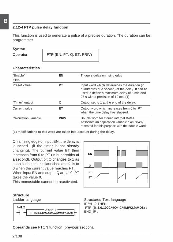
2/108___________________________________________________________________________
B2.12-4 FTP pulse delay function
This function is used to generate a pulse of a precise duration. The duration can beprogrammer.
Syntax
Operator FTP (EN, PT, Q, ET, PRIV)
Characteristics
"Enable" EN Triggers delay on rising edgeinput
Preset value PT Input word which determines the duration (inhundredths of a second) of the delay. It can beused to define a maximum delay of 5 min and27 s with a precision of 10 ms. (1)
"Timer" output Q Output set to 1 at the end of the delay.
Current value ET Output word which increases from 0 to PTwhen the time delay has elapsed.
Calculation variable PRIV Double word for storing internal states.Associate an application variable exclusivelyreserved for this purpose with the double word.
(1) modifications to this word are taken into account during the delay.
On a rising edge of input EN, the delay islaunched (if the timer is not alreadychanging). The current value ET thenincreases from 0 to PT (in hundredths ofa second). Output bit Q changes to 1 assoon as the timer is launched and falls to0 when the current value reaches PT.When input EN and output Q are at 0, PTtakes the value 0.This monostable cannot be reactivated.
StructureLadder language Structured Text language
IF %I1.2 THEN FTP (%I3.0,1000,%Q4.0,%MW2,%MD8) ;END_IF ;
Operands see FTON function (previous section).
EN
Q
ET
PT
FTP (%I3.0,1000,%Q4.0,%MW2,%MD8)OPERATE
%I1,2
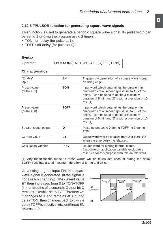
Description of advanced instructions 2
___________________________________________________________________________2/109
B2.12-5 FPULSOR function for generating square wave signals
This function is used to generate a periodic square wave signal. Its pulse width canbe set to 1 or 0 via the program using 2 timers :• TON : on-delay (for pulse at 1).• TOFF : off-delay (for pulse at 0).
Syntax
Operator FPULSOR (EN, TON, TOFF, Q, ET, PRIV)
Characteristics
"Enable" EN Triggers the generation of a square wave signalinput on rising edge.
Preset value TON Input word which determines the duration (in(pulse at 1) hundredths of a second (pulse set to 1)) of the
delay. It can be used to define a maximumduration of 5 min and 27 s with a precision of 10ms. (1)
Preset value TOFF Input word which determines the duration (in(pulse at 0) hundredths of a second (pulse set to 0)) of the
delay. It can be used to define a maximumduration of 5 min and 27 s with a precision of 10ms. (1)
Square signal output Q Pulse output set to 0 during TOFF, to 1 duringTON.
Current value ET Output word which increases from 0 to TON+TOFFwhen the time delay has elapsed.
Calculation variable PRIV Double word for storing internal states.Associate an application variable exclusivelyreserved for this purpose with this double word.
(1) Any modifications made to these words will be taken into account during the delay.TOFF+TON has a total maximum duration of 5 min and 27 s.
On a rising edge of input EN, the squarewave signal is generated (if the signal isnot already changing). The current valueET then increases from 0 to TON+TOFF(in hundredths of a second). Output bit Qremains at 0 while delay TOFF is effective;it changes to 1 and remains at 1 duringdelay TON, then changes back to 0 whiledelay TOFF is effective, etc, until input ENreturns to 0.
TOFF
TON
TOFF TOFF
TONTON+TOFF
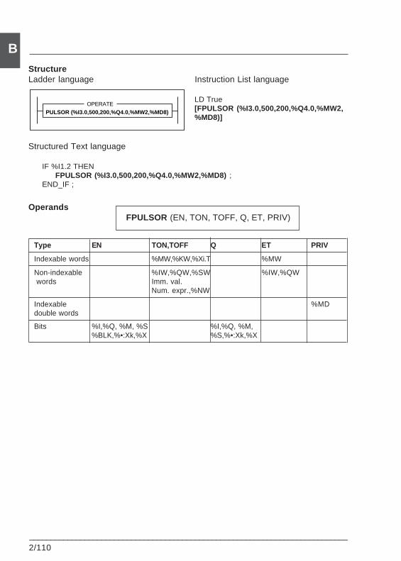
2/110___________________________________________________________________________
BStructureLadder language Instruction List language
LD True[FPULSOR (%I3.0,500,200,%Q4.0,%MW2,%MD8)]
Structured Text language
IF %I1.2 THENFPULSOR (%I3.0,500,200,%Q4.0,%MW2,%MD8) ;
END_IF ;
OperandsFPULSOR (EN, TON, TOFF, Q, ET, PRIV)
Type EN TON,TOFF Q ET PRIV
Indexable words %MW,%KW,%Xi.T %MW
Non-indexable %IW,%QW,%SW %IW,%QW words Imm. val.
Num. expr.,%NW
Indexable %MDdouble words
Bits %I,%Q, %M, %S %I,%Q, %M,%BLK,%•:Xk,%X %S,%•:Xk,%X
PULSOR (%I3.0,500,200,%Q4.0,%MW2,%MD8)OPERATE
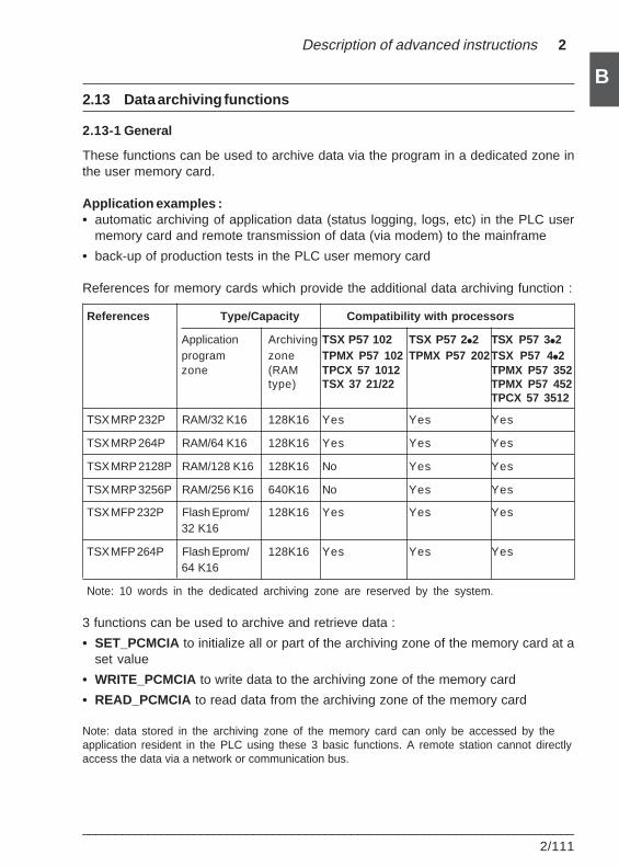
Description of advanced instructions 2
___________________________________________________________________________2/111
B2.13 Data archiving functions
2.13-1 General
These functions can be used to archive data via the program in a dedicated zone inthe user memory card.
Application examples :• automatic archiving of application data (status logging, logs, etc) in the PLC user
memory card and remote transmission of data (via modem) to the mainframe
• back-up of production tests in the PLC user memory card
References for memory cards which provide the additional data archiving function :
References Type/Capacity Compatibility with processors
Application Archiving TSX P57 102 TSX P57 2i2 TSX P57 3i2program zone TPMX P57 102 TPMX P57 202TSX P57 4i2zone (RAM TPCX 57 1012 TPMX P57 352
type) TSX 37 21/22 TPMX P57 452TPCX 57 3512
TSX MRP 232P RAM/32 K16 128K16 Yes Yes Yes
TSX MRP 264P RAM/64 K16 128K16 Yes Yes Yes
TSX MRP 2128P RAM/128 K16 128K16 No Yes Yes
TSX MRP 3256P RAM/256 K16 640K16 No Yes Yes
TSX MFP 232P Flash Eprom/ 128K16 Yes Yes Yes32 K16
TSX MFP 264P Flash Eprom/ 128K16 Yes Yes Yes64 K16
Note: 10 words in the dedicated archiving zone are reserved by the system.
3 functions can be used to archive and retrieve data :
• SET_PCMCIA to initialize all or part of the archiving zone of the memory card at aset value
• WRITE_PCMCIA to write data to the archiving zone of the memory card
• READ_PCMCIA to read data from the archiving zone of the memory card
Note: data stored in the archiving zone of the memory card can only be accessed by theapplication resident in the PLC using these 3 basic functions. A remote station cannot directlyaccess the data via a network or communication bus.
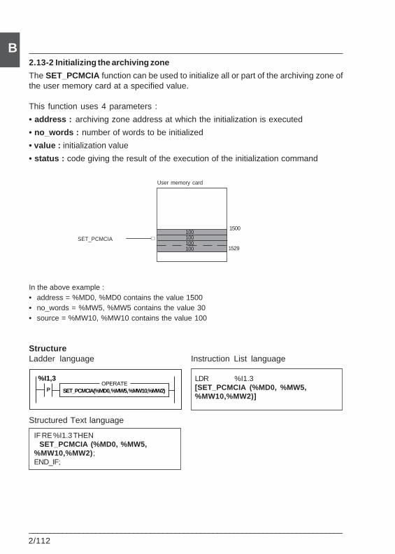
2/112___________________________________________________________________________
B2.13-2 Initializing the archiving zone
The SET_PCMCIA function can be used to initialize all or part of the archiving zone ofthe user memory card at a specified value.
This function uses 4 parameters :
• address : archiving zone address at which the initialization is executed
• no_words : number of words to be initialized
• value : initialization value
• status : code giving the result of the execution of the initialization command
In the above example :• address = %MD0, %MD0 contains the value 1500• no_words = %MW5, %MW5 contains the value 30• source = %MW10, %MW10 contains the value 100
StructureLadder language Instruction List language
LDR %I1.3[SET_PCMCIA (%MD0, %MW5,%MW10,%MW2)]
Structured Text language
IF RE %I1.3 THEN SET_PCMCIA (%MD0, %MW5,%MW10,%MW2);END_IF;
User memory card
1500
1529
∇SET_PCMCIA100100100100
SET_PCMCIA(%MD0, %MW5, %MW10,%MW2)OPERATE
%I1,3
P
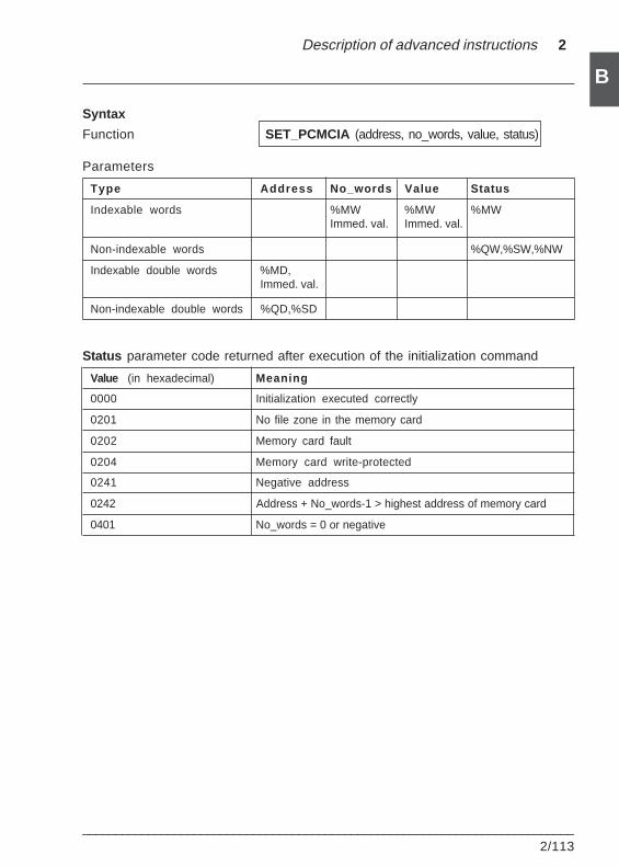
Description of advanced instructions 2
___________________________________________________________________________2/113
B
Syntax
Function SET_PCMCIA (address, no_words, value, status)
Parameters
Type Address No_words Value Status
Indexable words %MW %MW %MWImmed. val. Immed. val.
Non-indexable words %QW,%SW,%NW
Indexable double words %MD,Immed. val.
Non-indexable double words %QD,%SD
Status parameter code returned after execution of the initialization command
Value (in hexadecimal) Meaning
0000 Initialization executed correctly
0201 No file zone in the memory card
0202 Memory card fault
0204 Memory card write-protected
0241 Negative address
0242 Address + No_words-1 > highest address of memory card
0401 No_words = 0 or negative
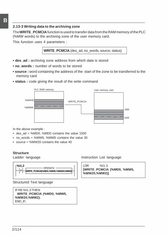
2/114___________________________________________________________________________
B2.13-3 Writing data to the archiving zone
The WRITE_PCMCIA function is used to transfer data from the RAM memory of the PLC(%MW words) to the archiving zone of the user memory card.
This function uses 4 parameters :
WRITE_PCMCIA (des_ad, no_words, source, status)
• des_ad : archiving zone address from which data is stored
• no_words : number of words to be stored
• source : word containing the address of the start of the zone to be transferred to thememory card
• status : code giving the result of the write command
In the above example :• des_ad = %MD0, %MD0 contains the value 1500• no_words = %MW5, %MW5 contains the value 30• source = %MW20 contains the value 40
StructureLadder language Instruction List language
LDR %I1.3[WRITE_PCMCIA (%MD0, %MW5,%MW20,%MW2)]
Structured Text language
IF RE %I1.3 THEN WRITE_PCMCIA (%MD0, %MW5,%MW20,%MW2);END_IF;
PLC RAM memory User memory card
1500
1529
%MW40
∇
%MW69
WRITE_PCMCIA
WRITE_PCMCIA(%MD0, %MW5, %MW20,%MW2)OPERATE
%I1,3
P

Description of advanced instructions 2
___________________________________________________________________________2/115
BSyntax
Function WRITE_PCMCIA (des_ad, no_words, source, status)
Parameters
Type Des_ad No_words Source Status
Indexable words %MW %MW %MWImmed. val. Immed. val.
Non-indexable words %QW,%SW,%NW
Indexable double words %MD,Immed. val.
Non-indexable double words %QD,%SD
Status parameter code returned after execution of the write command :
Value (in hexadecimal) Meaning
0000 Write executed correctly
0102 Source + No_words-1 > maximum number of %MWdeclared in the PLC
0104 No valid application or no %MW in the PLC
0201 No file zone in the memory card
0202 Memory card fault
0204 Memory card write-protected
0241 Des_ad < 0
0242 Des_ad + No_words-1 > highest address in the memorycard
0401 No_words = 0
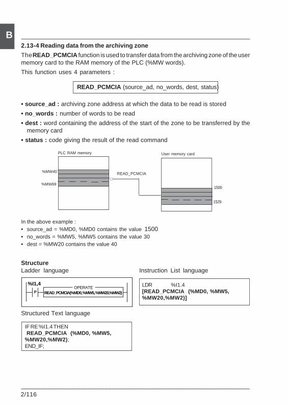
2/116___________________________________________________________________________
B2.13-4 Reading data from the archiving zone
The READ_PCMCIA function is used to transfer data from the archiving zone of the usermemory card to the RAM memory of the PLC (%MW words).
This function uses 4 parameters :
READ_PCMCIA (source_ad, no_words, dest, status)
• source_ad : archiving zone address at which the data to be read is stored
• no_words : number of words to be read
• dest : word containing the address of the start of the zone to be transferred by thememory card
• status : code giving the result of the read command
In the above example :• source_ad = %MD0, %MD0 contains the value 1500• no_words = %MW5, %MW5 contains the value 30• dest = %MW20 contains the value 40
StructureLadder language Instruction List language
LDR %I1.4[READ_PCMCIA (%MD0, %MW5,%MW20,%MW2)]
Structured Text language
IF RE %I1.4 THEN READ_PCMCIA (%MD0, %MW5,%MW20,%MW2);END_IF;
PLC RAM memory User memory card
1500
1529
%MW40∇
%MW69
READ_PCMCIA
READ_PCMCIA(%MD0, %MW5, %MW20,%MW2)OPERATE
%I1,4
P
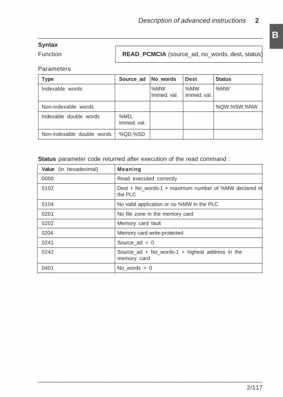
Description of advanced instructions 2
___________________________________________________________________________2/117
BSyntax
Function READ_PCMCIA (source_ad, no_words, dest, status)
Parameters
Type Source_ad No_words Dest Status
Indexable words %MW %MW %MWImmed. val. Immed. val.
Non-indexable words %QW,%SW,%NW
Indexable double words %MD,Immed. val.
Non-indexable double words %QD,%SD
Status parameter code returned after execution of the read command :
Value (in hexadecimal) Meaning
0000 Read executed correctly
0102 Dest + No_words-1 > maximum number of %MW declared inthe PLC
0104 No valid application or no %MW in the PLC
0201 No file zone in the memory card
0202 Memory card fault
0204 Memory card write-protected
0241 Source_ad < 0
0242 Source_ad + No_words-1 > highest address in thememory card
0401 No_words = 0

2/118___________________________________________________________________________
B
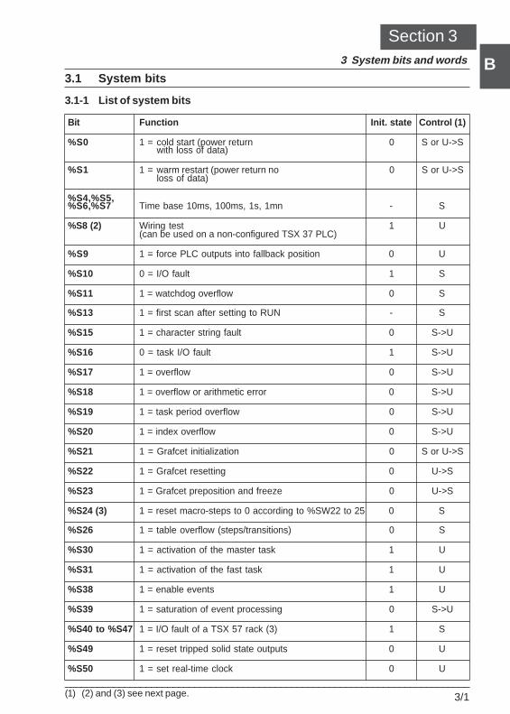
System bits and words 3
___________________________________________________________________________3/1
B
B3.1 System bits
3.1-1 List of system bits
Bit Function Init. state Control (1)
%S0 1 = cold start (power return 0 S or U->Swith loss of data)
%S1 1 = warm restart (power return no 0 S or U->Sloss of data)
%S4,%S5,%S6,%S7 Time base 10ms, 100ms, 1s, 1mn - S
%S8 (2) Wiring test 1 U(can be used on a non-configured TSX 37 PLC)
%S9 1 = force PLC outputs into fallback position 0 U
%S10 0 = I/O fault 1 S
%S11 1 = watchdog overflow 0 S
%S13 1 = first scan after setting to RUN - S
%S15 1 = character string fault 0 S->U
%S16 0 = task I/O fault 1 S->U
%S17 1 = overflow 0 S->U
%S18 1 = overflow or arithmetic error 0 S->U
%S19 1 = task period overflow 0 S->U
%S20 1 = index overflow 0 S->U
%S21 1 = Grafcet initialization 0 S or U->S
%S22 1 = Grafcet resetting 0 U->S
%S23 1 = Grafcet preposition and freeze 0 U->S
%S24 (3) 1 = reset macro-steps to 0 according to %SW22 to 25 0 S
%S26 1 = table overflow (steps/transitions) 0 S
%S30 1 = activation of the master task 1 U
%S31 1 = activation of the fast task 1 U
%S38 1 = enable events 1 U
%S39 1 = saturation of event processing 0 S->U
%S40 to %S47 1 = I/O fault of a TSX 57 rack (3) 1 S
%S49 1 = reset tripped solid state outputs 0 U
%S50 1 = set real-time clock 0 U
Section 33 System bits and words
(1) (2) and (3) see next page.
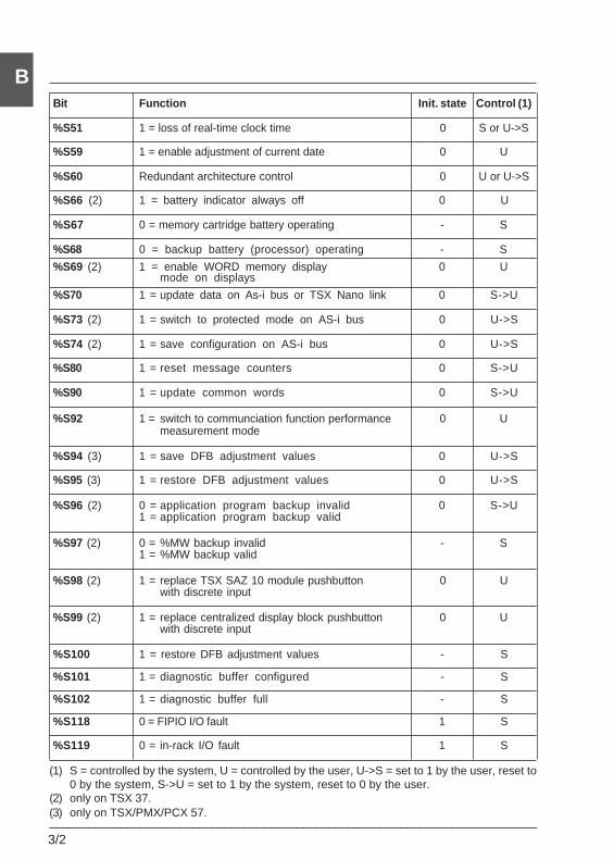
3/2___________________________________________________________________________
BBit Function Init. state Control (1)
%S51 1 = loss of real-time clock time 0 S or U->S
%S59 1 = enable adjustment of current date 0 U
%S60 Redundant architecture control 0 U or U->S
%S66 (2) 1 = battery indicator always off 0 U
%S67 0 = memory cartridge battery operating - S
%S68 0 = backup battery (processor) operating - S
%S69 (2) 1 = enable WORD memory display 0 Umode on displays
%S70 1 = update data on As-i bus or TSX Nano link 0 S->U
%S73 (2) 1 = switch to protected mode on AS-i bus 0 U->S
%S74 (2) 1 = save configuration on AS-i bus 0 U->S
%S80 1 = reset message counters 0 S->U
%S90 1 = update common words 0 S->U
%S92 1 = switch to communciation function performance 0 Umeasurement mode
%S94 (3) 1 = save DFB adjustment values 0 U->S
%S95 (3) 1 = restore DFB adjustment values 0 U->S
%S96 (2) 0 = application program backup invalid 0 S->U1 = application program backup valid
%S97 (2) 0 = %MW backup invalid - S1 = %MW backup valid
%S98 (2) 1 = replace TSX SAZ 10 module pushbutton 0 Uwith discrete input
%S99 (2) 1 = replace centralized display block pushbutton 0 Uwith discrete input
%S100 1 = restore DFB adjustment values - S
%S101 1 = diagnostic buffer configured - S
%S102 1 = diagnostic buffer full - S
%S118 0 = FIPIO I/O fault 1 S
%S119 0 = in-rack I/O fault 1 S
(1) S = controlled by the system, U = controlled by the user, U->S = set to 1 by the user, reset to0 by the system, S->U = set to 1 by the system, reset to 0 by the user.
(2) only on TSX 37.(3) only on TSX/PMX/PCX 57.
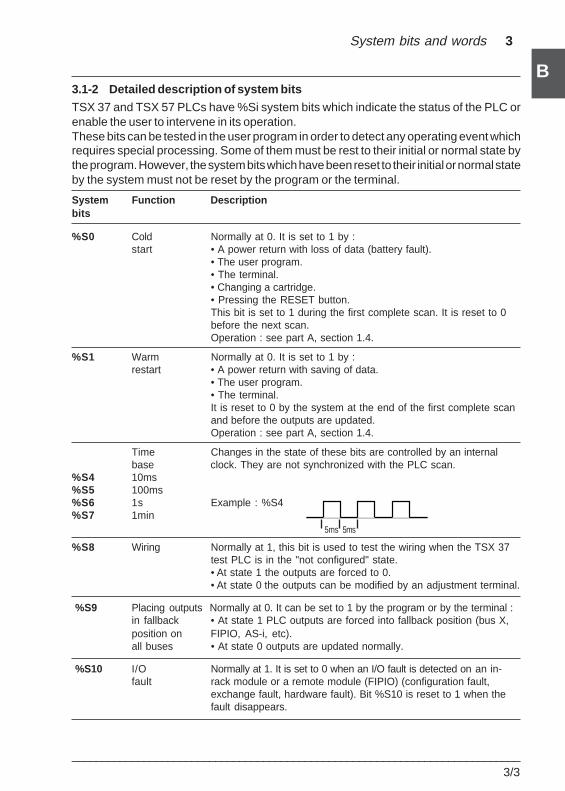
System bits and words 3
___________________________________________________________________________3/3
B
B3.1-2 Detailed description of system bits
TSX 37 and TSX 57 PLCs have %Si system bits which indicate the status of the PLC orenable the user to intervene in its operation.These bits can be tested in the user program in order to detect any operating event whichrequires special processing. Some of them must be rest to their initial or normal state bythe program. However, the system bits which have been reset to their initial or normal stateby the system must not be reset by the program or the terminal.
System Function Descriptionbits
%S0 Cold Normally at 0. It is set to 1 by :start • A power return with loss of data (battery fault).
• The user program.• The terminal.• Changing a cartridge.• Pressing the RESET button.This bit is set to 1 during the first complete scan. It is reset to 0before the next scan.Operation : see part A, section 1.4.
%S1 Warm Normally at 0. It is set to 1 by :restart • A power return with saving of data.
• The user program.• The terminal.It is reset to 0 by the system at the end of the first complete scanand before the outputs are updated.Operation : see part A, section 1.4.
Time Changes in the state of these bits are controlled by an internalbase clock. They are not synchronized with the PLC scan.
%S4 10ms%S5 100ms%S6 1s Example : %S4%S7 1min
%S8 Wiring Normally at 1, this bit is used to test the wiring when the TSX 37test PLC is in the "not configured" state.• At state 1 the outputs are forced to 0.• At state 0 the outputs can be modified by an adjustment terminal.
%S9 Placing outputs Normally at 0. It can be set to 1 by the program or by the terminal :in fallback • At state 1 PLC outputs are forced into fallback position (bus X,position on FIPIO, AS-i, etc).all buses • At state 0 outputs are updated normally.
%S10 I/O Normally at 1. It is set to 0 when an I/O fault is detected on an in-fault rack module or a remote module (FIPIO) (configuration fault,
exchange fault, hardware fault). Bit %S10 is reset to 1 when thefault disappears.
5ms 5ms
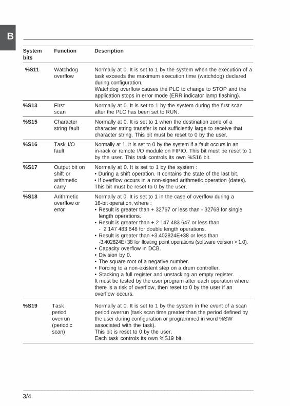
3/4___________________________________________________________________________
BSystem Function Descriptionbits
%S11 Watchdog Normally at 0. It is set to 1 by the system when the execution of aoverflow task exceeds the maximum execution time (watchdog) declared
during configuration.Watchdog overflow causes the PLC to change to STOP and theapplication stops in error mode (ERR indicator lamp flashing).
%S13 First Normally at 0. It is set to 1 by the system during the first scanscan after the PLC has been set to RUN.
%S15 Character Normally at 0. It is set to 1 when the destination zone of astring fault character string transfer is not sufficiently large to receive that
character string. This bit must be reset to 0 by the user.
%S16 Task I/O Normally at 1. It is set to 0 by the system if a fault occurs in anfault in-rack or remote I/O module on FIPIO. This bit must be reset to 1
by the user. This task controls its own %S16 bit.
%S17 Output bit on Normally at 0. It is set to 1 by the system :shift or • During a shift operation. It contains the state of the last bit.arithmetic • If overflow occurs in a non-signed arithmetic operation (dates).carry This bit must be reset to 0 by the user.
%S18 Arithmetic Normally at 0. It is set to 1 in the case of overflow during aoverflow or 16-bit operation, where :error • Result is greater than + 32767 or less than - 32768 for single
length operations.• Result is greater than + 2 147 483 647 or less than
- 2 147 483 648 for double length operations.• Result is greater than +3.402824E+38 or less than
-3.402824E+38 for floating point operations (software version > 1.0).• Capacity overflow in DCB.• Division by 0.• The square root of a negative number.• Forcing to a non-existent step on a drum controller.• Stacking a full register and unstacking an empty register.It must be tested by the user program after each operation wherethere is a risk of overflow, then reset to 0 by the user if anoverflow occurs.
%S19 Task Normally at 0. It is set to 1 by the system in the event of a scanperiod period overrun (task scan time greater than the period defined byoverrun the user during configuration or programmed in word %SW(periodic associated with the task).scan) This bit is reset to 0 by the user.
Each task controls its own %S19 bit.
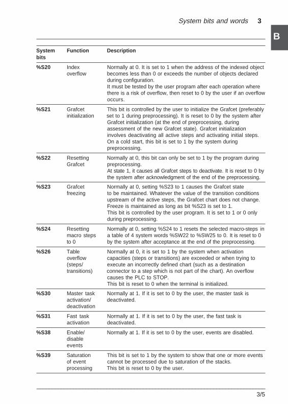
System bits and words 3
___________________________________________________________________________3/5
B
BSystem Function Descriptionbits
%S20 Index Normally at 0. It is set to 1 when the address of the indexed objectoverflow becomes less than 0 or exceeds the number of objects declared
during configuration.It must be tested by the user program after each operation wherethere is a risk of overflow, then reset to 0 by the user if an overflowoccurs.
%S21 Grafcet This bit is controlled by the user to initialize the Grafcet (preferablyinitialization set to 1 during preprocessing). It is reset to 0 by the system after
Grafcet initialization (at the end of preprocessing, duringassessment of the new Grafcet state). Grafcet initializationinvolves deactivating all active steps and activating initial steps.On a cold start, this bit is set to 1 by the system duringpreprocessing.
%S22 Resetting Normally at 0, this bit can only be set to 1 by the program duringGrafcet preprocessing.
At state 1, it causes all Grafcet steps to deactivate. It is reset to 0 bythe system after acknowledgment of the end of the preprocessing.
%S23 Grafcet Normally at 0, setting %S23 to 1 causes the Grafcet statefreezing to be maintained. Whatever the value of the transition conditions
upstream of the active steps, the Grafcet chart does not change.Freeze is maintained as long as bit %S23 is set to 1.This bit is controlled by the user program. It is set to 1 or 0 onlyduring preprocessing.
%S24 Resetting Normally at 0, setting %S24 to 1 resets the selected macro-steps inmacro steps a table of 4 system words %SW22 to %SW25 to 0. It is reset to 0to 0 by the system after acceptance at the end of the preprocessing.
%S26 Table Normally at 0, it is set to 1 by the system when activationoverflow capacities (steps or transitions) are exceeded or when trying to(steps/ execute an incorrectly defined chart (such as a destinationtransitions) connector to a step which is not part of the chart). An overflow
causes the PLC to STOP.This bit is reset to 0 when the terminal is initialized.
%S30 Master task Normally at 1. If it is set to 0 by the user, the master task isactivation/ deactivated.deactivation
%S31 Fast task Normally at 1. If it is set to 0 by the user, the fast task isactivation deactivated.
%S38 Enable/ Normally at 1. If it is set to 0 by the user, events are disabled.disableevents
%S39 Saturation This bit is set to 1 by the system to show that one or more eventsof event cannot be processed due to saturation of the stacks.processing This bit is reset to 0 by the user.
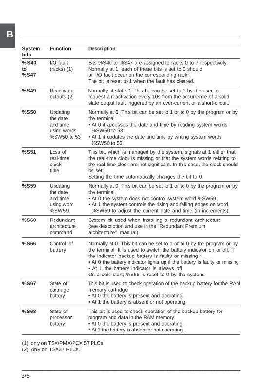
3/6___________________________________________________________________________
BSystem Function Descriptionbits
%S40 I/O fault Bits %S40 to %S47 are assigned to racks 0 to 7 respectively.to (racks) (1) Normally at 1, each of these bits is set to 0 should%S47 an I/O fault occur on the corresponding rack.
The bit is reset to 1 when the fault has cleared.
%S49 Reactivate Normally at state 0. This bit can be set to 1 by the user tooutputs (2) request a reactivation every 10s from the occurrence of a solid
state output fault triggered by an over-current or a short-circuit.
%S50 Updating Normally at 0. This bit can be set to 1 or to 0 by the program or bythe date the terminal.and time • At 0 it accesses the date and time by reading system wordsusing words %SW50 to 53.%SW50 to 53 • At 1 it updates the date and time by writing system words
%SW50 to 53.
%S51 Loss of This bit, which is managed by the system, signals at 1 either thatreal-time the real-time clock is missing or that the system words relating toclock the real-time clock are not significant. In this case, the clock shouldtime be set.
Setting the time automatically changes the bit to 0.
%S59 Updating Normally at 0. This bit can be set to 1 or to 0 by the program or bythe date the terminal.and time • At 0 the system does not control system word %SW59.using word • At 1 the system controls the rising and falling edges on word%SW59 %SW59 to adjust the current date and time (in increments).
%S60 Redundant System bit used when installing a redundant architecturearchitecture (see description and use in the "Redundant Premiumcommand architecture" manual).
%S66 Control of Normally at 0. This bit can be set to 1 or to 0 by the program or bybattery the terminal. It is used to switch the battery indicator on or off, if
the indicator backup battery is faulty or missing :• At 0 the battery indicator lights up if the battery is faulty or missing• At 1 the battery indicator is always offOn a cold start, %S66 is reset to 0 by the system.
%S67 State of This bit is used to check operation of the backup battery for the RAMcartridge memory cartridge.battery • At 0 the battery is present and operating.
• At 1 the battery is absent or not operating.
%S68 State of This bit is used to check operation of the backup battery forprocessor program and data in the RAM memory.battery • At 0 the battery is present and operating.
• At 1 the battery is absent or not operating.
(1) only on TSX/PMX/PCX 57 PLCs.(2) only on TSX37 PLCs.
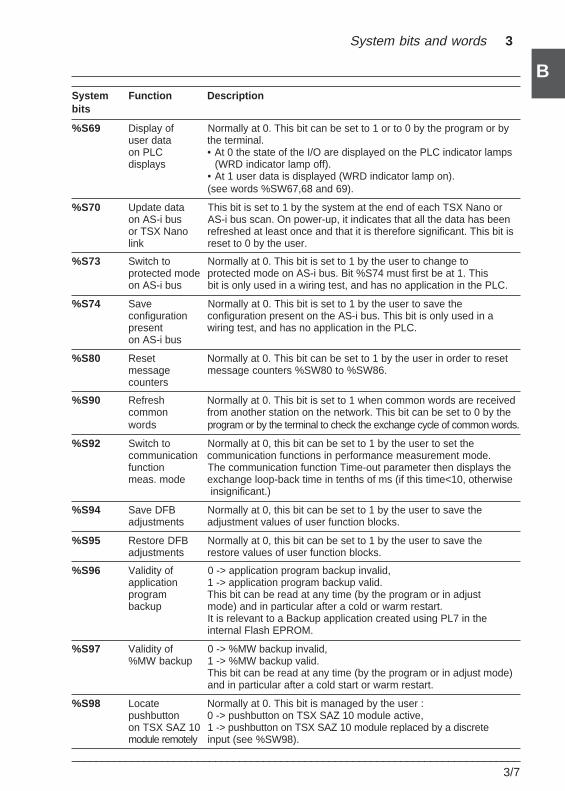
System bits and words 3
___________________________________________________________________________3/7
B
BSystem Function Descriptionbits
%S69 Display of Normally at 0. This bit can be set to 1 or to 0 by the program or byuser data the terminal.on PLC • At 0 the state of the I/O are displayed on the PLC indicator lampsdisplays (WRD indicator lamp off).
• At 1 user data is displayed (WRD indicator lamp on).(see words %SW67,68 and 69).
%S70 Update data This bit is set to 1 by the system at the end of each TSX Nano oron AS-i bus AS-i bus scan. On power-up, it indicates that all the data has beenor TSX Nano refreshed at least once and that it is therefore significant. This bit islink reset to 0 by the user.
%S73 Switch to Normally at 0. This bit is set to 1 by the user to change toprotected mode protected mode on AS-i bus. Bit %S74 must first be at 1. Thison AS-i bus bit is only used in a wiring test, and has no application in the PLC.
%S74 Save Normally at 0. This bit is set to 1 by the user to save theconfiguration configuration present on the AS-i bus. This bit is only used in apresent wiring test, and has no application in the PLC.on AS-i bus
%S80 Reset Normally at 0. This bit can be set to 1 by the user in order to resetmessage message counters %SW80 to %SW86.counters
%S90 Refresh Normally at 0. This bit is set to 1 when common words are receivedcommon from another station on the network. This bit can be set to 0 by thewords program or by the terminal to check the exchange cycle of common words.
%S92 Switch to Normally at 0, this bit can be set to 1 by the user to set thecommunication communication functions in performance measurement mode.function The communication function Time-out parameter then displays themeas. mode exchange loop-back time in tenths of ms (if this time<10, otherwise
insignificant.)
%S94 Save DFB Normally at 0, this bit can be set to 1 by the user to save theadjustments adjustment values of user function blocks.
%S95 Restore DFB Normally at 0, this bit can be set to 1 by the user to save theadjustments restore values of user function blocks.
%S96 Validity of 0 -> application program backup invalid,application 1 -> application program backup valid.program This bit can be read at any time (by the program or in adjustbackup mode) and in particular after a cold or warm restart.
It is relevant to a Backup application created using PL7 in theinternal Flash EPROM.
%S97 Validity of 0 -> %MW backup invalid,%MW backup 1 -> %MW backup valid.
This bit can be read at any time (by the program or in adjust mode)and in particular after a cold start or warm restart.
%S98 Locate Normally at 0. This bit is managed by the user :pushbutton 0 -> pushbutton on TSX SAZ 10 module active,on TSX SAZ 10 1 -> pushbutton on TSX SAZ 10 module replaced by a discretemodule remotely input (see %SW98).
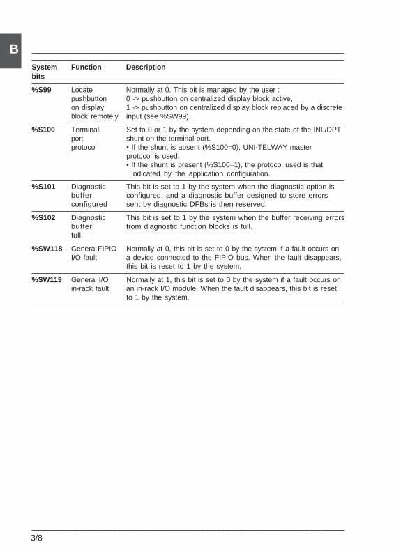
3/8___________________________________________________________________________
BSystem Function Descriptionbits
%S99 Locate Normally at 0. This bit is managed by the user :pushbutton 0 -> pushbutton on centralized display block active,on display 1 -> pushbutton on centralized display block replaced by a discreteblock remotely input (see %SW99).
%S100 Terminal Set to 0 or 1 by the system depending on the state of the INL/DPTport shunt on the terminal port.protocol • If the shunt is absent (%S100=0), UNI-TELWAY master
protocol is used.• If the shunt is present (%S100=1), the protocol used is that
indicated by the application configuration.
%S101 Diagnostic This bit is set to 1 by the system when the diagnostic option isbuffer configured, and a diagnostic buffer designed to store errorsconfigured sent by diagnostic DFBs is then reserved.
%S102 Diagnostic This bit is set to 1 by the system when the buffer receiving errorsbuffer from diagnostic function blocks is full.full
%SW118 General FIPIO Normally at 0, this bit is set to 0 by the system if a fault occurs onI/O fault a device connected to the FIPIO bus. When the fault disappears,
this bit is reset to 1 by the system.
%SW119 General I/O Normally at 1, this bit is set to 0 by the system if a fault occurs onin-rack fault an in-rack I/O module. When the fault disappears, this bit is reset
to 1 by the system.
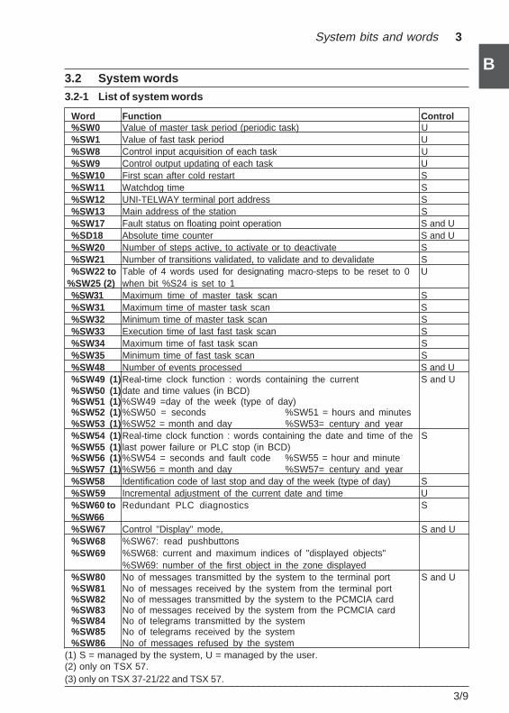
System bits and words 3
___________________________________________________________________________3/9
B
B3.2 System words
3.2-1 List of system words
Word Function Control%SW0 Value of master task period (periodic task) U%SW1 Value of fast task period U%SW8 Control input acquisition of each task U%SW9 Control output updating of each task U%SW10 First scan after cold restart S%SW11 Watchdog time S%SW12 UNI-TELWAY terminal port address S%SW13 Main address of the station S%SW17 Fault status on floating point operation S and U%SD18 Absolute time counter S and U%SW20 Number of steps active, to activate or to deactivate S%SW21 Number of transitions validated, to validate and to devalidate S%SW22 to Table of 4 words used for designating macro-steps to be reset to 0 U
%SW25 (2) when bit %S24 is set to 1%SW31 Maximum time of master task scan S%SW31 Maximum time of master task scan S%SW32 Minimum time of master task scan S%SW33 Execution time of last fast task scan S%SW34 Maximum time of fast task scan S%SW35 Minimum time of fast task scan S%SW48 Number of events processed S and U%SW49 (1)Real-time clock function : words containing the current S and U%SW50 (1)date and time values (in BCD)%SW51 (1)%SW49 =day of the week (type of day)%SW52 (1)%SW50 = seconds %SW51 = hours and minutes%SW53 (1)%SW52 = month and day %SW53= century and year%SW54 (1)Real-time clock function : words containing the date and time of the S%SW55 (1) last power failure or PLC stop (in BCD)%SW56 (1)%SW54 = seconds and fault code %SW55 = hour and minute%SW57 (1)%SW56 = month and day %SW57= century and year%SW58 Identification code of last stop and day of the week (type of day) S%SW59 Incremental adjustment of the current date and time U%SW60 to Redundant PLC diagnostics S%SW66%SW67 Control "Display" mode, S and U%SW68 %SW67: read pushbuttons%SW69 %SW68: current and maximum indices of "displayed objects"
%SW69: number of the first object in the zone displayed%SW80 No of messages transmitted by the system to the terminal port S and U%SW81 No of messages received by the system from the terminal port%SW82 No of messages transmitted by the system to the PCMCIA card%SW83 No of messages received by the system from the PCMCIA card%SW84 No of telegrams transmitted by the system%SW85 No of telegrams received by the system%SW86 No of messages refused by the system
(1) S = managed by the system, U = managed by the user.(2) only on TSX 57.(3) only on TSX 37-21/22 and TSX 57.
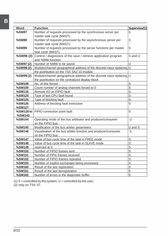
3/10___________________________________________________________________________
BWord Function Supervisor(1)%SW87 Number of requests processed by the synchronous server per S
master task cycle (MAST).%SW88 Number of requests processed by the asynchronous server per S
master task cycle (MAST).%SW89 Number of requests processed by the server functions per master S
task cycle (MAST).%SW96 (2) Control / diagnostics of the save / retrieve application program S and U
and %MW function%SW97 (2) Number of %MW to be saved U%SW98 (2) Module/channel geographical address of the discrete input replacing U
the pushbutton on the TSX SAZ 10 module%SW99 (2) Module/channel geographical address of the discrete input replacing U
the pushbutton on the centralized display block%SW108 No. of bits forced S%SW109 Count number of analog channels forced to 0 S%SW116 Remote I/O on FIPIO fault S%SW124 Type of last CPU fault found S%SW125 Type of blocking fault S%SW126 Address of blocking fault instruction S%SW127%SW128 to FIPIO connection point fault S %SW143%SW144 Operating mode of the bus arbitrator and producer/consumer U
on the FIPIO bus%SW145 Modification of the bus arbiter parameters U and S%SW146 Visualisation of the bus arbiter function and producer/consumer S
on the FIPIO bus%SW147 Value of bus cycle time of the task in FREE mode S%SW148 Value of bus cycle time of the task in SLAVE mode S%SW149 reserved at 0 S%SW150 Number of FIPIO frames sent S%SW151 Number of FIPio frames received S%SW152 Number of FIPIO frames repeated S%SW155 Number of explicit exchanges being processed S%SW160 Result of the last registration S%SW161 Result of the last deregistration S%SW162 Number of errors in the diagnostic buffer S
(1) S = controlled by the system, U = controlled by the user,(2) only on TSX 37.
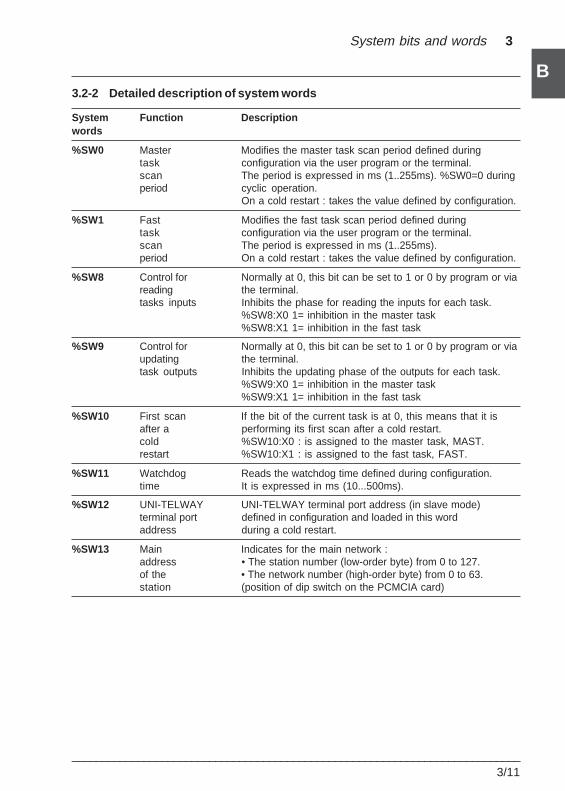
System bits and words 3
___________________________________________________________________________3/11
B
B3.2-2 Detailed description of system words
System Function Descriptionwords
%SW0 Master Modifies the master task scan period defined duringtask configuration via the user program or the terminal.scan The period is expressed in ms (1..255ms). %SW0=0 duringperiod cyclic operation.
On a cold restart : takes the value defined by configuration.
%SW1 Fast Modifies the fast task scan period defined duringtask configuration via the user program or the terminal.scan The period is expressed in ms (1..255ms).period On a cold restart : takes the value defined by configuration.
%SW8 Control for Normally at 0, this bit can be set to 1 or 0 by program or viareading the terminal.tasks inputs Inhibits the phase for reading the inputs for each task.
%SW8:X0 1= inhibition in the master task%SW8:X1 1= inhibition in the fast task
%SW9 Control for Normally at 0, this bit can be set to 1 or 0 by program or viaupdating the terminal.task outputs Inhibits the updating phase of the outputs for each task.
%SW9:X0 1= inhibition in the master task%SW9:X1 1= inhibition in the fast task
%SW10 First scan If the bit of the current task is at 0, this means that it isafter a performing its first scan after a cold restart.cold %SW10:X0 : is assigned to the master task, MAST.restart %SW10:X1 : is assigned to the fast task, FAST.
%SW11 Watchdog Reads the watchdog time defined during configuration.time It is expressed in ms (10...500ms).
%SW12 UNI-TELWAY UNI-TELWAY terminal port address (in slave mode)terminal port defined in configuration and loaded in this wordaddress during a cold restart.
%SW13 Main Indicates for the main network :address • The station number (low-order byte) from 0 to 127.of the • The network number (high-order byte) from 0 to 63.station (position of dip switch on the PCMCIA card)
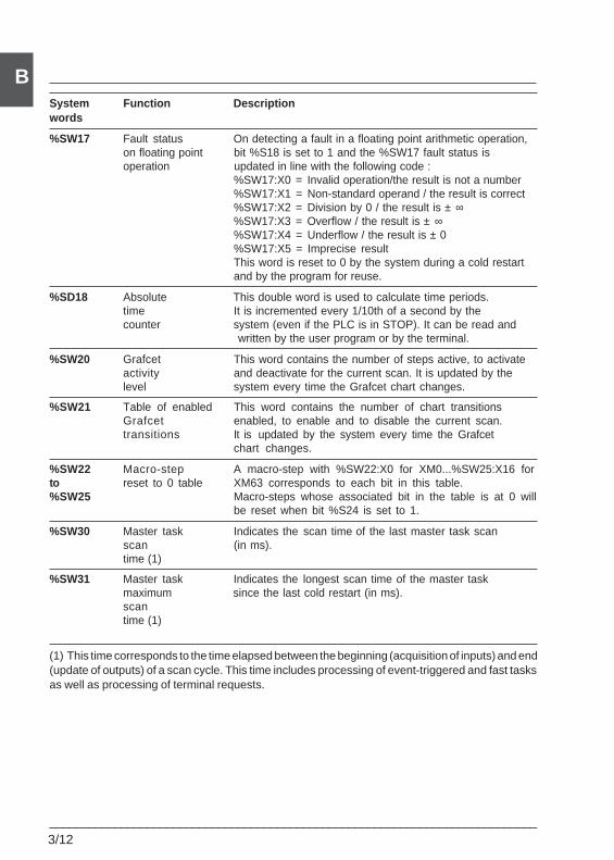
3/12___________________________________________________________________________
BSystem Function Descriptionwords
%SW17 Fault status On detecting a fault in a floating point arithmetic operation,on floating point bit %S18 is set to 1 and the %SW17 fault status isoperation updated in line with the following code :
%SW17:X0 = Invalid operation/the result is not a number%SW17:X1 = Non-standard operand / the result is correct%SW17:X2 = Division by 0 / the result is ± ∞%SW17:X3 = Overflow / the result is ± ∞%SW17:X4 = Underflow / the result is ± 0%SW17:X5 = Imprecise resultThis word is reset to 0 by the system during a cold restartand by the program for reuse.
%SD18 Absolute This double word is used to calculate time periods.time It is incremented every 1/10th of a second by thecounter system (even if the PLC is in STOP). It can be read and
written by the user program or by the terminal.
%SW20 Grafcet This word contains the number of steps active, to activateactivity and deactivate for the current scan. It is updated by thelevel system every time the Grafcet chart changes.
%SW21 Table of enabled This word contains the number of chart transitionsGrafcet enabled, to enable and to disable the current scan.transitions It is updated by the system every time the Grafcet
chart changes.
%SW22 Macro-step A macro-step with %SW22:X0 for XM0...%SW25:X16 forto reset to 0 table XM63 corresponds to each bit in this table.%SW25 Macro-steps whose associated bit in the table is at 0 will
be reset when bit %S24 is set to 1.
%SW30 Master task Indicates the scan time of the last master task scanscan (in ms).time (1)
%SW31 Master task Indicates the longest scan time of the master taskmaximum since the last cold restart (in ms).scantime (1)
(1) This time corresponds to the time elapsed between the beginning (acquisition of inputs) and end(update of outputs) of a scan cycle. This time includes processing of event-triggered and fast tasksas well as processing of terminal requests.
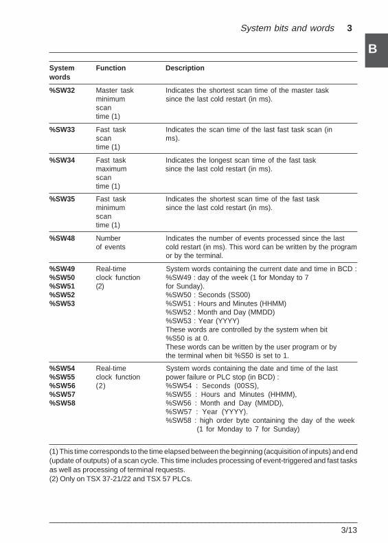
System bits and words 3
___________________________________________________________________________3/13
B
BSystem Function Descriptionwords
%SW32 Master task Indicates the shortest scan time of the master taskminimum since the last cold restart (in ms).scantime (1)
%SW33 Fast task Indicates the scan time of the last fast task scan (inscan ms).time (1)
%SW34 Fast task Indicates the longest scan time of the fast taskmaximum since the last cold restart (in ms).scantime (1)
%SW35 Fast task Indicates the shortest scan time of the fast taskminimum since the last cold restart (in ms).scantime (1)
%SW48 Number Indicates the number of events processed since the lastof events cold restart (in ms). This word can be written by the program
or by the terminal.
%SW49 Real-time System words containing the current date and time in BCD :%SW50 clock function %SW49 : day of the week (1 for Monday to 7%SW51 (2) for Sunday).%SW52 %SW50 : Seconds (SS00)%SW53 %SW51 : Hours and Minutes (HHMM)
%SW52 : Month and Day (MMDD)%SW53 : Year (YYYY)These words are controlled by the system when bit%S50 is at 0.These words can be written by the user program or bythe terminal when bit %S50 is set to 1.
%SW54 Real-time System words containing the date and time of the last%SW55 clock function power failure or PLC stop (in BCD) :%SW56 (2) %SW54 : Seconds (00SS),%SW57 %SW55 : Hours and Minutes (HHMM),%SW58 %SW56 : Month and Day (MMDD),
%SW57 : Year (YYYY).%SW58 : high order byte containing the day of the week
(1 for Monday to 7 for Sunday)
(1) This time corresponds to the time elapsed between the beginning (acquisition of inputs) and end(update of outputs) of a scan cycle. This time includes processing of event-triggered and fast tasksas well as processing of terminal requests.(2) Only on TSX 37-21/22 and TSX 57 PLCs.
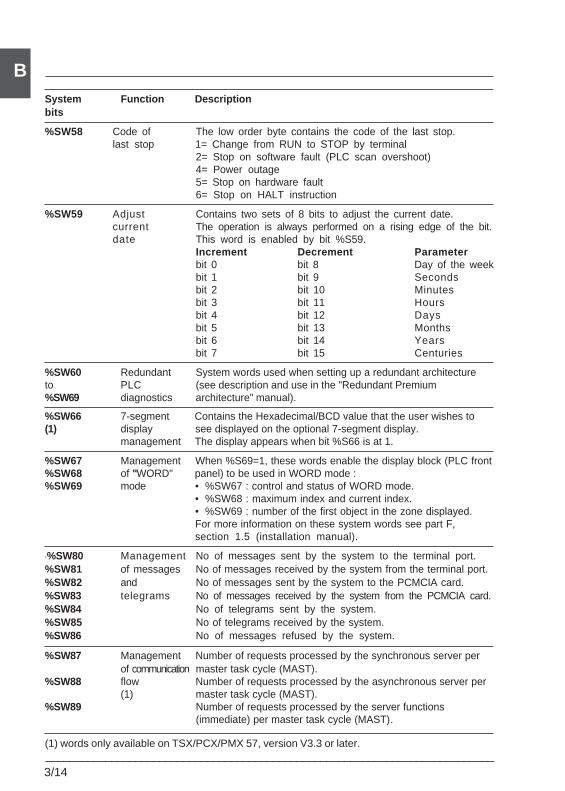
3/14___________________________________________________________________________
BSystem Function Descriptionbits
%SW58 Code of The low order byte contains the code of the last stop.last stop 1= Change from RUN to STOP by terminal
2= Stop on software fault (PLC scan overshoot)4= Power outage5= Stop on hardware fault6= Stop on HALT instruction
%SW59 Adjust Contains two sets of 8 bits to adjust the current date.current The operation is always performed on a rising edge of the bit.date This word is enabled by bit %S59.
Increment Decrement Parameterbit 0 bit 8 Day of the weekbit 1 bit 9 Secondsbit 2 bit 10 Minutesbit 3 bit 11 Hoursbit 4 bit 12 Daysbit 5 bit 13 Monthsbit 6 bit 14 Yearsbit 7 bit 15 Centuries
%SW60 Redundant System words used when setting up a redundant architectureto PLC (see description and use in the "Redundant Premium%SW69 diagnostics architecture" manual).
%SW66 7-segment Contains the Hexadecimal/BCD value that the user wishes to(1) display see displayed on the optional 7-segment display.
management The display appears when bit %S66 is at 1.
%SW67 Management When %S69=1, these words enable the display block (PLC front%SW68 of "WORD" panel) to be used in WORD mode :%SW69 mode • %SW67 : control and status of WORD mode.
• %SW68 : maximum index and current index.• %SW69 : number of the first object in the zone displayed.For more information on these system words see part F,section 1.5 (installation manual).
c%SW80 Management No of messages sent by the system to the terminal port.%SW81 of messages No of messages received by the system from the terminal port.%SW82 and No of messages sent by the system to the PCMCIA card.%SW83 telegrams No of messages received by the system from the PCMCIA card.%SW84 No of telegrams sent by the system.%SW85 No of telegrams received by the system.%SW86 No of messages refused by the system.
%SW87 Management Number of requests processed by the synchronous server perof communication master task cycle (MAST).
%SW88 flow Number of requests processed by the asynchronous server per(1) master task cycle (MAST).
%SW89 Number of requests processed by the server functions(immediate) per master task cycle (MAST).
(1) words only available on TSX/PCX/PMX 57, version V3.3 or later.
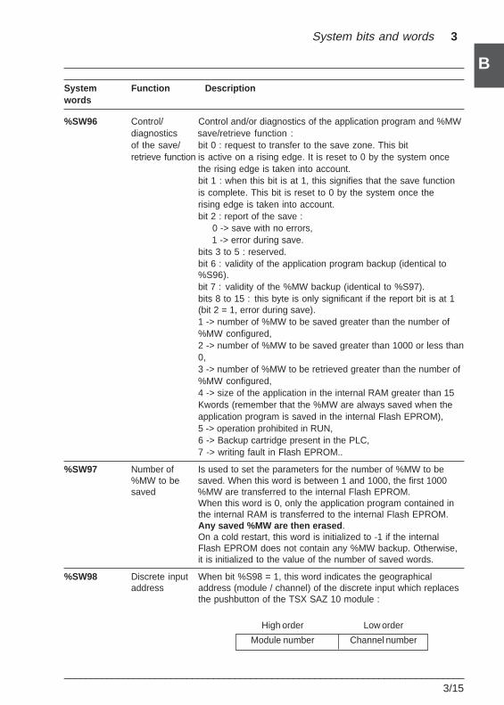
System bits and words 3
___________________________________________________________________________3/15
B
BSystem Function Descriptionwords
%SW96 Control/ Control and/or diagnostics of the application program and %MWdiagnostics save/retrieve function :of the save/ bit 0 : request to transfer to the save zone. This bitretrieve function is active on a rising edge. It is reset to 0 by the system once
the rising edge is taken into account.bit 1 : when this bit is at 1, this signifies that the save functionis complete. This bit is reset to 0 by the system once therising edge is taken into account.bit 2 : report of the save : 0 -> save with no errors, 1 -> error during save.bits 3 to 5 : reserved.bit 6 : validity of the application program backup (identical to%S96).bit 7 : validity of the %MW backup (identical to %S97).bits 8 to 15 : this byte is only significant if the report bit is at 1(bit 2 = 1, error during save).1 -> number of %MW to be saved greater than the number of%MW configured,2 -> number of %MW to be saved greater than 1000 or less than0,3 -> number of %MW to be retrieved greater than the number of%MW configured,4 -> size of the application in the internal RAM greater than 15Kwords (remember that the %MW are always saved when theapplication program is saved in the internal Flash EPROM),5 -> operation prohibited in RUN,6 -> Backup cartridge present in the PLC,7 -> writing fault in Flash EPROM..
%SW97 Number of Is used to set the parameters for the number of %MW to be%MW to be saved. When this word is between 1 and 1000, the first 1000saved %MW are transferred to the internal Flash EPROM.
When this word is 0, only the application program contained inthe internal RAM is transferred to the internal Flash EPROM.Any saved %MW are then erased .On a cold restart, this word is initialized to -1 if the internalFlash EPROM does not contain any %MW backup. Otherwise,it is initialized to the value of the number of saved words.
%SW98 Discrete input When bit %S98 = 1, this word indicates the geographicaladdress address (module / channel) of the discrete input which replaces
the pushbutton of the TSX SAZ 10 module :
High order Low order
Module number Channel number
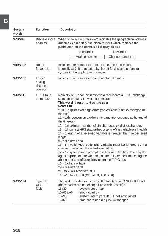
3/16___________________________________________________________________________
BSystem Function Descriptionwords
%SW99 Discrete input When bit %S99 = 1, this word indicates the geographical addressaddress (module / channel) of the discrete input which replaces the
pushbutton on the centralized display block :
High order Low order
Module number Channel number
%SW108 No. of Indicates the number of forced bits in the application.forced bits Normally at 0, it is updated by the bit forcing and unforcing
system in the application memory.
%SW109 Forced Indicates the number of forced analog channels.analogchannelcounter
%SW116 FIPIO fault Normally at 0, each bit in this word represents a FIPIO exchangein the task status in the task in which it is tested.
This word is reset to 0 by the user.%SW 116 :x0 = 1 explicit exchange error (the variable is not exchanged onthe bus)x1 = 1 timeout on an explicit exchange (no response at the end ofthe timeout)x2 = 1 maximum number of simultaneous explicit exchangesx3 = 1 incorrect MPS status (the contents of the variable are invalid)x4 = 1 length of a received variable is greater than the declaredlengthx5 = reserved at 0x6 =1 invalid PDU code (the variable must be ignored by thechannel manager), the agent is initializedx7 = 1 asynchronous promptness timeout : the time taken by theagent to produce the variable has been exceeded, indicating theabsence of a configured device on the FIPIO busx8 = 1 channel faultx9 = reserved at 0x10 to x14 = reserved at 0x15 =1 global fault (OR bits 3, 4, 6, 7, 8).
%SW124 Type of The system writes in this word the last type of CPU fault foundCPU (these codes are not changed on a cold restart) :fault 16#30 : system code fault
16#60 to 64 : stack overflow16#90 : system interrupt fault : IT not anticipated16#53 : time out fault during I/O exchanges
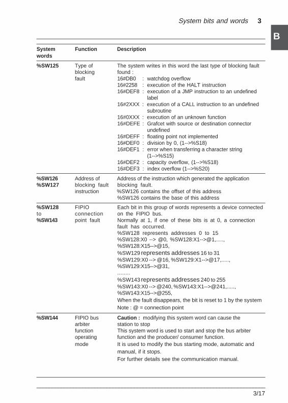
System bits and words 3
___________________________________________________________________________3/17
B
BSystem Function Descriptionwords
%SW125 Type of The system writes in this word the last type of blocking faultblocking found :fault 16#DB0 : watchdog overflow
16#2258 : execution of the HALT instruction16#DEF8 : execution of a JMP instruction to an undefined
label16#2XXX : execution of a CALL instruction to an undefined
subroutine16#0XXX : execution of an unknown function16#DEFE : Grafcet with source or destination connector
undefined16#DEFF : floating point not implemented16#DEF0 : division by 0, (1-->%S18)16#DEF1 : error when transferring a character string
(1-->%S15)16#DEF2 : capacity overflow, (1-->%S18)16#DEF3 : index overflow (1-->%S20)
%SW126 Address of Address of the instruction which generated the application%SW127 blocking fault blocking fault.
instruction %SW126 contains the offset of this address%SW126 contains the base of this address
%SW128 FIPIO Each bit in this group of words represents a device connectedto connection on the FIPIO bus.%SW143 point fault Normally at 1, if one of these bits is at 0, a connection
fault has occurred.%SW128 represents addresses 0 to 15%SW128:X0 --> @0, %SW128:X1-->@1,.....,%SW128:X15-->@15,%SW129 represents addresses 16 to 31%SW129:X0 --> @16, %SW129:X1-->@17,.....,%SW129:X15-->@31,........%SW143 represents addresses 240 to 255%SW143:X0 --> @240, %SW143:X1-->@241,.....,%SW143:X15-->@255,When the fault disappears, the bit is reset to 1 by the systemNote : @ = connection point
%SW144 FIPIO bus Caution : modifying this system word can cause thearbiter station to stopfunction This system word is used to start and stop the bus arbiteroperating function and the producer/ consumer function.mode It is used to modify the bus starting mode, automatic and
manual, if it stops.For further details see the communication manual.
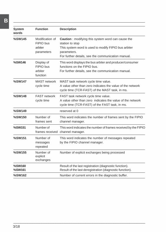
3/18___________________________________________________________________________
BSystem Function Descriptionwords
%SW145 Modification of Caution : modifying this system word can cause theFIPIO bus station to stoparbiter This system word is used to modify FIPIO bus arbiterparameters parameters.
For further details, see the communication manual.
%SW146 Display of This word displays the bus arbiter and producer/consumerFIPIO bus functions on the FIPIO bus.arbiter For further details, see the communication manual.function
%SW147 MAST network MAST task network cycle time value.cycle time A value other than zero indicates the value of the network
cycle time (TCR-FAST) of the MAST task, in ms.
%SW148 FAST network FAST task network cycle time value.cycle time A value other than zero indicates the value of the network
cycle time (TCR-FAST) of the FAST task, in ms.
%SW149 reserved at 0
%SW150 Number of This word indicates the number of frames sent by the FIPIOframes sent channel manager.
%SW151 Number of This word indicates the number of frames received by the FIPIOframes received channel manager.
%SW151 Number of This word indicates the number of messages repeatedmessages by the FIPIO channel manager.repeated
%SW155 Number of Number of explicit exchanges being processedexplicitexchanges
%SW160 Result of the last registration (diagnostic function).%SW161 Result of the last deregistration (diagnostic function).
%SW162 Number of current errors in the diagnostic buffer.
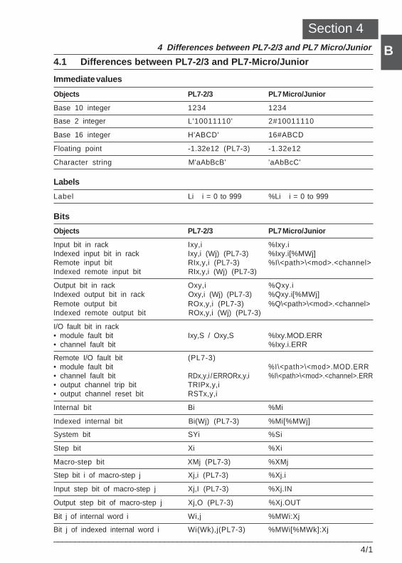
Differences between PL7-2/3 and PL7 Micro 4
___________________________________________________________________________4/1
B
B4.1 Differences between PL7-2/3 and PL7-Micro/Junior
Immediate values
Objects PL7-2/3 PL7 Micro/Junior
Base 10 integer 1234 1234
Base 2 integer L'10011110' 2#10011110
Base 16 integer H'ABCD' 16#ABCD
Floating point -1.32e12 (PL7-3) -1.32e12
Character string M'aAbBcB' 'aAbBcC'
Labels
Label Li i = 0 to 999 %Li i = 0 to 999
Bits
Objects PL7-2/3 PL7 Micro/Junior
Input bit in rack Ixy,i %Ixy.iIndexed input bit in rack Ixy,i (Wj) (PL7-3) %Ixy.i[%MWj]Remote input bit RIx,y,i (PL7-3) %I\<path>\<mod>.<channel>Indexed remote input bit RIx,y,i (Wj) (PL7-3)
Output bit in rack Oxy,i %Qxy.iIndexed output bit in rack Oxy,i (Wj) (PL7-3) %Qxy.i[%MWj]Remote output bit ROx,y,i (PL7-3) %Q\<path>\<mod>.<channel>Indexed remote output bit ROx,y,i (Wj) (PL7-3)
I/O fault bit in rack• module fault bit Ixy,S / Oxy,S %Ixy.MOD.ERR• channel fault bit %Ixy.i.ERR
Remote I/O fault bit (PL7-3)• module fault bit %I\<path>\<mod>.MOD.ERR• channel fault bit RDx,y,i / ERRORx,y,i %I\<path>\<mod>.<channel>.ERR• output channel trip bit TRIPx,y,i• output channel reset bit RSTx,y,i
Internal bit Bi %Mi
Indexed internal bit Bi(Wj) (PL7-3) %Mi[%MWj]
System bit SYi %Si
Step bit Xi %Xi
Macro-step bit XMj (PL7-3) %XMj
Step bit i of macro-step j Xj,i (PL7-3) %Xj.i
Input step bit of macro-step j Xj,I (PL7-3) %Xj.IN
Output step bit of macro-step j Xj,O (PL7-3) %Xj.OUT
Bit j of internal word i Wi,j %MWi:Xj
Bit j of indexed internal word i Wi(Wk),j(PL7-3) %MWi[%MWk]:Xj
Section 44 Differences between PL7-2/3 and PL7 Micro/Junior
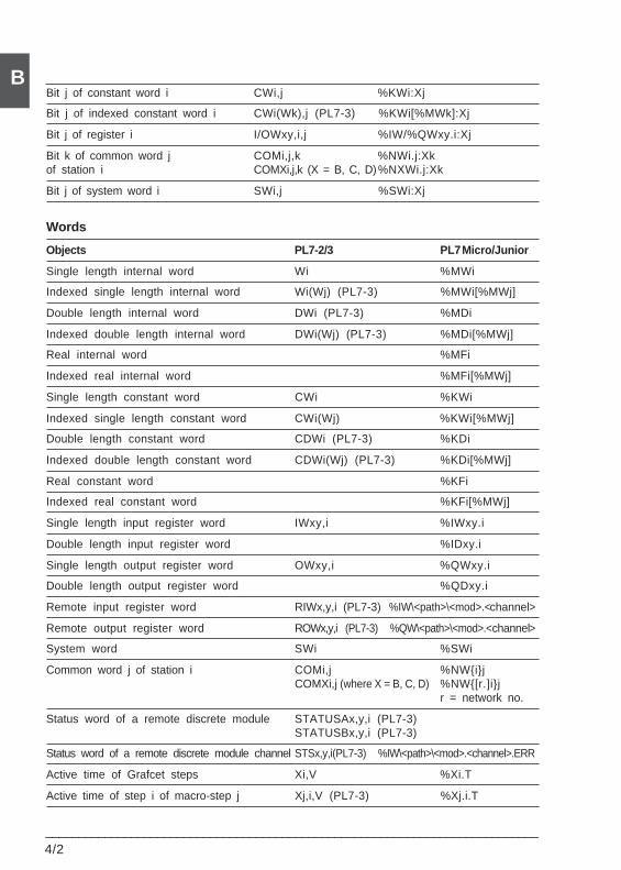
4/2___________________________________________________________________________
BBit j of constant word i CWi,j %KWi:Xj
Bit j of indexed constant word i CWi(Wk),j (PL7-3) %KWi[%MWk]:Xj
Bit j of register i I/OWxy,i,j %IW/%QWxy.i:Xj
Bit k of common word j COMi,j,k %NWi.j:Xkof station i COMXi,j,k (X = B, C, D)%NXWi.j:Xk
Bit j of system word i SWi,j %SWi:Xj
Words
Objects PL7-2/3 PL7 Micro/Junior
Single length internal word Wi %MWi
Indexed single length internal word Wi(Wj) (PL7-3) %MWi[%MWj]
Double length internal word DWi (PL7-3) %MDi
Indexed double length internal word DWi(Wj) (PL7-3) %MDi[%MWj]
Real internal word %MFi
Indexed real internal word %MFi[%MWj]
Single length constant word CWi %KWi
Indexed single length constant word CWi(Wj) %KWi[%MWj]
Double length constant word CDWi (PL7-3) %KDi
Indexed double length constant word CDWi(Wj) (PL7-3) %KDi[%MWj]
Real constant word %KFi
Indexed real constant word %KFi[%MWj]
Single length input register word IWxy,i %IWxy.i
Double length input register word %IDxy.i
Single length output register word OWxy,i %QWxy.i
Double length output register word %QDxy.i
Remote input register word RIWx,y,i (PL7-3) %IW\<path>\<mod>.<channel>
Remote output register word ROWx,y,i (PL7-3) %QW\<path>\<mod>.<channel>
System word SWi %SWi
Common word j of station i COMi,j %NW{i}jCOMXi,j (where X = B, C, D) %NW{[r.]i}j
r = network no.
Status word of a remote discrete module STATUSAx,y,i (PL7-3)STATUSBx,y,i (PL7-3)
Status word of a remote discrete module channel STSx,y,i(PL7-3) %IW\<path>\<mod>.<channel>.ERR
Active time of Grafcet steps Xi,V %Xi.T
Active time of step i of macro-step j Xj,i,V (PL7-3) %Xj.i.T
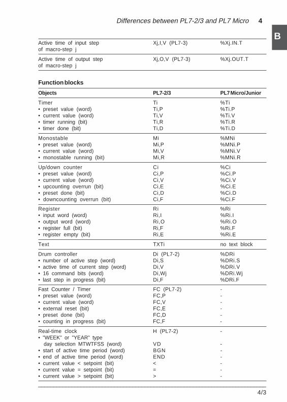
Differences between PL7-2/3 and PL7 Micro 4
___________________________________________________________________________4/3
B
BActive time of input step Xj,I,V (PL7-3) %Xj.IN.Tof macro-step j
Active time of output step Xj,O,V (PL7-3) %Xj.OUT.Tof macro-step j
Function blocks
Objects PL7-2/3 PL7 Micro/Junior
Timer Ti %Ti• preset value (word) Ti,P %Ti.P• current value (word) Ti,V %Ti.V• timer running (bit) Ti,R %Ti.R• timer done (bit) Ti,D %Ti.D
Monostable Mi %MNi• preset value (word) Mi,P %MNi.P• current value (word) Mi,V %MNi.V• monostable running (bit) Mi,R %MNi.R
Up/down counter Ci %Ci• preset value (word) Ci,P %Ci.P• current value (word) Ci,V %Ci.V• upcounting overrun (bit) Ci,E %Ci.E• preset done (bit) Ci,D %Ci.D• downcounting overrun (bit) Ci,F %Ci.F
Register Ri %Ri• input word (word) Ri,I %Ri.I• output word (word) Ri,O %Ri.O• register full (bit) Ri,F %Ri.F• register empty (bit) Ri,E %Ri.E
Text TXTi no text block
Drum controller Di (PL7-2) %DRi• number of active step (word) Di,S %DRi.S• active time of current step (word) Di,V %DRi.V• 16 command bits (word) Di,Wj %DRi.Wj• last step in progress (bit) Di,F %DRi.F
Fast Counter / Timer FC (PL7-2) -• preset value (word) FC,P -• current value (word) FC,V -• external reset (bit) FC,E -• preset done (bit) FC,D -• counting in progress (bit) FC,F -
Real-time clock H (PL7-2) -• "WEEK" or "YEAR" type day selection MTWTFSS (word) VD -• start of active time period (word) BGN -• end of active time period (word) END -• current value < setpoint (bit) < -• current value = setpoint (bit) = -• current value > setpoint (bit) > -
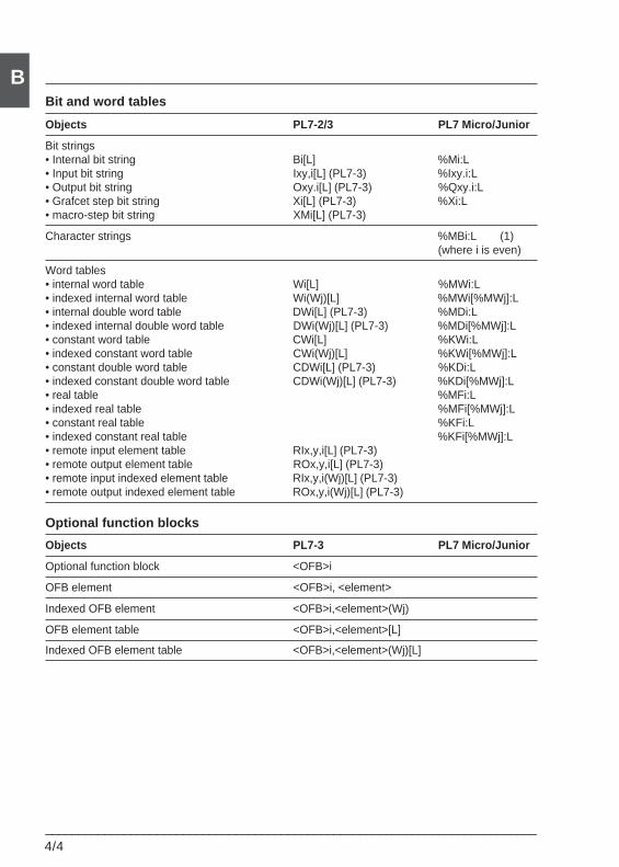
4/4___________________________________________________________________________
BBit and word tables
Objects PL7-2/3 PL7 Micro/Junior
Bit strings• Internal bit string Bi[L] %Mi:L• Input bit string Ixy,i[L] (PL7-3) %Ixy.i:L• Output bit string Oxy.i[L] (PL7-3) %Qxy.i:L• Grafcet step bit string Xi[L] (PL7-3) %Xi:L• macro-step bit string XMi[L] (PL7-3)
Character strings %MBi:L (1)(where i is even)
Word tables• internal word table Wi[L] %MWi:L• indexed internal word table Wi(Wj)[L] %MWi[%MWj]:L• internal double word table DWi[L] (PL7-3) %MDi:L• indexed internal double word table DWi(Wj)[L] (PL7-3) %MDi[%MWj]:L• constant word table CWi[L] %KWi:L• indexed constant word table CWi(Wj)[L] %KWi[%MWj]:L• constant double word table CDWi[L] (PL7-3) %KDi:L• indexed constant double word table CDWi(Wj)[L] (PL7-3) %KDi[%MWj]:L• real table %MFi:L• indexed real table %MFi[%MWj]:L• constant real table %KFi:L• indexed constant real table %KFi[%MWj]:L• remote input element table RIx,y,i[L] (PL7-3)• remote output element table ROx,y,i[L] (PL7-3)• remote input indexed element table RIx,y,i(Wj)[L] (PL7-3)• remote output indexed element table ROx,y,i(Wj)[L] (PL7-3)
Optional function blocks
Objects PL7-3 PL7 Micro/Junior
Optional function block <OFB>i
OFB element <OFB>i, <element>
Indexed OFB element <OFB>i,<element>(Wj)
OFB element table <OFB>i,<element>[L]
Indexed OFB element table <OFB>i,<element>(Wj)[L]
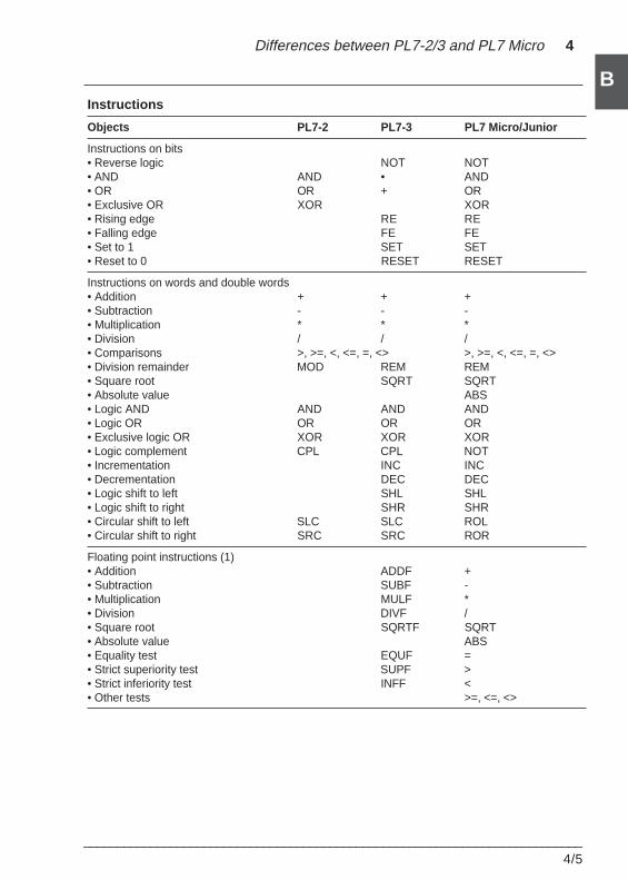
Differences between PL7-2/3 and PL7 Micro 4
___________________________________________________________________________4/5
B
BInstructions
Objects PL7-2 PL7-3 PL7 Micro/Junior
Instructions on bits• Reverse logic NOT NOT• AND AND • AND• OR OR + OR• Exclusive OR XOR XOR• Rising edge RE RE• Falling edge FE FE• Set to 1 SET SET• Reset to 0 RESET RESET
Instructions on words and double words• Addition + + +• Subtraction - - -• Multiplication * * *• Division / / /• Comparisons >, >=, <, <=, =, <> >, >=, <, <=, =, <>• Division remainder MOD REM REM• Square root SQRT SQRT• Absolute value ABS• Logic AND AND AND AND• Logic OR OR OR OR• Exclusive logic OR XOR XOR XOR• Logic complement CPL CPL NOT• Incrementation INC INC• Decrementation DEC DEC• Logic shift to left SHL SHL• Logic shift to right SHR SHR• Circular shift to left SLC SLC ROL• Circular shift to right SRC SRC ROR
Floating point instructions (1)• Addition ADDF +• Subtraction SUBF -• Multiplication MULF *• Division DIVF /• Square root SQRTF SQRT• Absolute value ABS• Equality test EQUF =• Strict superiority test SUPF >• Strict inferiority test INFF <• Other tests >=, <=, <>
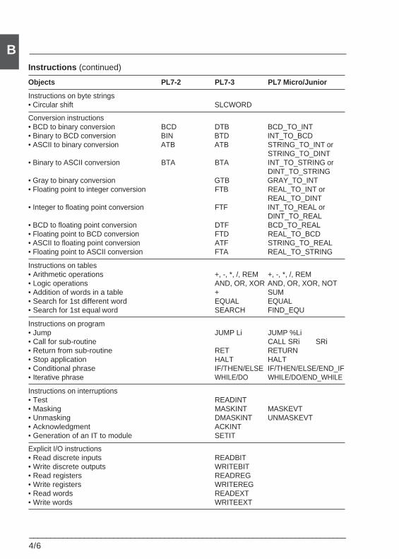
4/6___________________________________________________________________________
BInstructions (continued)
Objects PL7-2 PL7-3 PL7 Micro/Junior
Instructions on byte strings• Circular shift SLCWORD
Conversion instructions• BCD to binary conversion BCD DTB BCD_TO_INT• Binary to BCD conversion BIN BTD INT_TO_BCD• ASCII to binary conversion ATB ATB STRING_TO_INT or
STRING_TO_DINT• Binary to ASCII conversion BTA BTA INT_TO_STRING or
DINT_TO_STRING• Gray to binary conversion GTB GRAY_TO_INT• Floating point to integer conversion FTB REAL_TO_INT or
REAL_TO_DINT• Integer to floating point conversion FTF INT_TO_REAL or
DINT_TO_REAL• BCD to floating point conversion DTF BCD_TO_REAL• Floating point to BCD conversion FTD REAL_TO_BCD• ASCII to floating point conversion ATF STRING_TO_REAL• Floating point to ASCII conversion FTA REAL_TO_STRING
Instructions on tables• Arithmetic operations +, -, *, /, REM +, -, *, /, REM• Logic operations AND, OR, XOR AND, OR, XOR, NOT• Addition of words in a table + SUM• Search for 1st different word EQUAL EQUAL• Search for 1st equal word SEARCH FIND_EQU
Instructions on program• Jump JUMP Li JUMP %Li• Call for sub-routine CALL SRi SRi• Return from sub-routine RET RETURN• Stop application HALT HALT• Conditional phrase IF/THEN/ELSE IF/THEN/ELSE/END_IF• Iterative phrase WHILE/DO WHILE/DO/END_WHILE
Instructions on interruptions• Test READINT• Masking MASKINT MASKEVT• Unmasking DMASKINT UNMASKEVT• Acknowledgment ACKINT• Generation of an IT to module SETIT
Explicit I/O instructions• Read discrete inputs READBIT• Write discrete outputs WRITEBIT• Read registers READREG• Write registers WRITEREG• Read words READEXT• Write words WRITEEXT
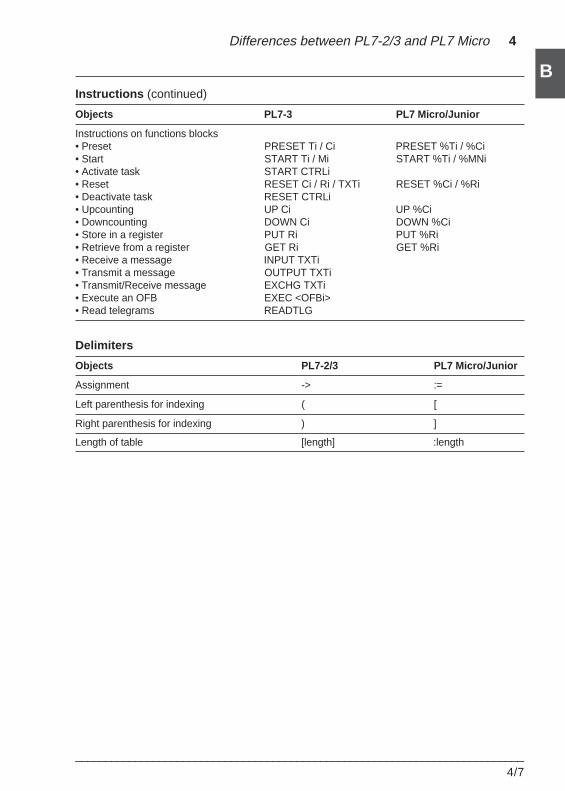
Differences between PL7-2/3 and PL7 Micro 4
___________________________________________________________________________4/7
B
BInstructions (continued)
Objects PL7-3 PL7 Micro/Junior
Instructions on functions blocks• Preset PRESET Ti / Ci PRESET %Ti / %Ci• Start START Ti / Mi START %Ti / %MNi• Activate task START CTRLi• Reset RESET Ci / Ri / TXTi RESET %Ci / %Ri• Deactivate task RESET CTRLi• Upcounting UP Ci UP %Ci• Downcounting DOWN Ci DOWN %Ci• Store in a register PUT Ri PUT %Ri• Retrieve from a register GET Ri GET %Ri• Receive a message INPUT TXTi• Transmit a message OUTPUT TXTi• Transmit/Receive message EXCHG TXTi• Execute an OFB EXEC <OFBi>• Read telegrams READTLG
Delimiters
Objects PL7-2/3 PL7 Micro/Junior
Assignment -> :=
Left parenthesis for indexing ( [
Right parenthesis for indexing ) ]
Length of table [length] :length

4/8___________________________________________________________________________
B
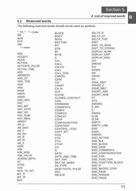
List of reserved words 5
___________________________________________________________________________5/1
B
B
Section 55 List of reserved words
5.1 Reserved words
The following reserved words should not be used as symbols.
*_TO_* * = LetterSRiAUXiEVTiXMi i = entier
ABSACCEPTACOSACTIONACTIVATE_PULSEACTIVE_TIMEADDADDRESSADD_DTADD_TODADRANDANDFANDNANDRAND_ARXANYANY_BITANY_DATEANY_INTANY_NUMANY_REALARRAYAR_DAR_DINTAR_FAR_INTAR_RAR_WAR_XASINASKASK_MSGASK_VALUEASSIGN_KEYSATATANAUXBCD_TO_INTBIT_DBIT_WBLK
BLOCKBODYBOOLBOTTOMBTIBTRBYBYTECCALCALCCALCNCALLCALL_COILCANCELCASECDCHARTCH_MCLKCLOSECLOSED_CONTACTCOILCOMMANDCOMMENTSCOMP4COMPCHCONCATCONFCONFIGURATIONCONSTANTCONTROL_LEDSCOPY_BITCOSCTDCTUCTUDCUDDATEDATE_AND_TIMEDAT_FMTDAY_OF_WEEKDA_TYPEDEACTIVATE_PULSEDECDELETE
DELTA_DDELTA_DTDELTA_TODDINTDINT_TO_REALDINT_TO_STRINGDISPLAY_ALRMDISPLAY_GRPDISPLAY_MSGDIVDMOVEDODOWNDRDRUMDSDSHL_RBITDSHRZ_CDSHR_RBITDSORT_ARDDSORT_ARWDTDTSDWORDD_BITEEBOOLELSEELSIFEMPTYEMPTY_LINEENDENDCENDCNEND_ACTIONEND_BLKEND_BLOCKEND_CASEEND_COMMENTSEND_CONFIGURATIONEND_FOREND_FUNCTIONEND_FUNCTION_BLOCKEND_IFEND_MACRO_STEPEND_PAGEEND_PHRASEEND_PROG
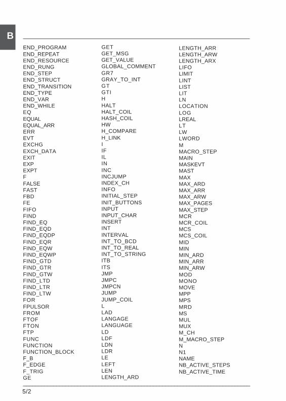
5/2___________________________________________________________________________
BEND_PROGRAMEND_REPEATEND_RESOURCEEND_RUNGEND_STEPEND_STRUCTEND_TRANSITIONEND_TYPEEND_VAREND_WHILEEQEQUALEQUAL_ARRERREVTEXCHGEXCH_DATAEXITEXPEXPTFFALSEFASTFBDFEFIFOFINDFIND_EQFIND_EQDFIND_EQDPFIND_EQRFIND_EQWFIND_EQWPFIND_GTDFIND_GTRFIND_GTWFIND_LTDFIND_LTRFIND_LTWFORFPULSORFROMFTOFFTONFTPFUNCFUNCTIONFUNCTION_BLOCKF_BF_EDGEF_TRIGGE
LENGTH_ARRLENGTH_ARWLENGTH_ARXLIFOLIMITLINTLISTLITLNLOCATIONLOGLREALLTLWLWORDMMACRO_STEPMAINMASKEVTMASTMAXMAX_ARDMAX_ARRMAX_ARWMAX_PAGESMAX_STEPMCRMCR_COILMCSMCS_COILMIDMINMIN_ARDMIN_ARRMIN_ARWMODMONOMOVEMPPMPSMRDMSMULMUXM_CHM_MACRO_STEPNN1NAMENB_ACTIVE_STEPSNB_ACTIVE_TIME
GETGET_MSGGET_VALUEGLOBAL_COMMENTGR7GRAY_TO_INTGTGTIHHALTHALT_COILHASH_COILHWH_COMPAREH_LINKIIFILININCINCJUMPINDEX_CHINFOINITIAL_STEPINIT_BUTTONSINPUTINPUT_CHARINSERTINTINTERVALINT_TO_BCDINT_TO_REALINT_TO_STRINGITBITSJMPJMPCJMPCNJUMPJUMP_COILLLADLANGAGELANGUAGELDLDFLDNLDRLELEFTLENLENGTH_ARD
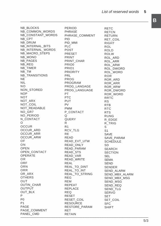
List of reserved words 5
___________________________________________________________________________5/3
B
BNB_BLOCKSNB_COMMON_WORDSNB_CONSTANT_WORDSNB_CPTNB_DRUMNB_INTERNAL_BITSNB_INTERNAL_WORDSNB_MACRO_STEPSNB_MONONB_PAGESNB_REGNB_TIMERNB_TMNB_TRANSITIONSNENILNONON_STOREDNOPNOTNOT_ARXNOT_COILNOT_READABLENO_GR7NO_PERIODN_CONTACTOOCCUROCCUR_ARDOCCUR_ARROCCUR_ARWOFONOPENOPEN_CONTACTOPERATEORORFORNORROR_ARXOTHERSOUTOUTIN_CHAROUTPUTOUT_BLKPP0P1PAGEPAGE_COMMENTPANEL_CMD
PERIODPHRASEPHRASE_COMMENTPIDPID_MMIPLCPOSTPRESETPRINTPRINT_CHARPRIO0PRIO1PRIORITYPRLPROGPROGRAMPROG_LANGAGEPROG_LANGUAGEPTPTCPUTPVPWMP_CONTACTQQUERYRR1RCV_TLGREREADREAD_EVT_UTWREAD_ONLYREAD_PARAMREAD_STSREAD_VARREAD_WRITEREALREAL_TO_DINTREAL_TO_INTREAL_TO_STRINGREGREMREPEATREPLACEREQRESETRESET_COILRESOURCERESTORE_PARAMRETRETAIN
RETCRETCNRETURNRET_COILRIGHTROLROLDROLWROL_ARDROL_ARRROL_ARWROL_DWORDROL_WORDRORROR_ARDROR_ARRROR_ARWROR_DWORDROR_WORDRRTCRSRTBRTCRTSRUNGR_EDGER_TRIGSS1SAVESAVE_PARAMSCHEDULESDSEARCHSECTIONSELSEMASENDSENDERSEND_ALARMSEND_MBX_ALARMSEND_MBX_MSGSEND_MSGSEND_REQSEND_TLGSERVOSETSET_COILSFCSHIFT
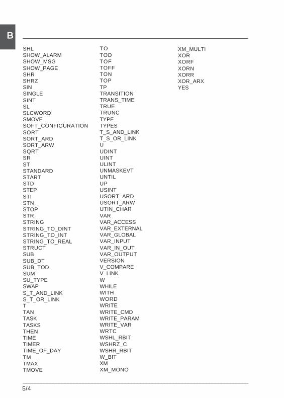
5/4___________________________________________________________________________
BSHLSHOW_ALARMSHOW_MSGSHOW_PAGESHRSHRZSINSINGLESINTSLSLCWORDSMOVESOFT_CONFIGURATIONSORTSORT_ARDSORT_ARWSQRTSRSTSTANDARDSTARTSTDSTEPSTISTNSTOPSTRSTRINGSTRING_TO_DINTSTRING_TO_INTSTRING_TO_REALSTRUCTSUBSUB_DTSUB_TODSUMSU_TYPESWAPS_T_AND_LINKS_T_OR_LINKTTANTASKTASKSTHENTIMETIMERTIME_OF_DAYTMTMAXTMOVE
TOTODTOFTOFFTONTOPTPTRANSITIONTRANS_TIMETRUETRUNCTYPETYPEST_S_AND_LINKT_S_OR_LINKUUDINTUINTULINTUNMASKEVTUNTILUPUSINTUSORT_ARDUSORT_ARWUTIN_CHARVARVAR_ACCESSVAR_EXTERNALVAR_GLOBALVAR_INPUTVAR_IN_OUTVAR_OUTPUTVERSIONV_COMPAREV_LINKWWHILEWITHWORDWRITEWRITE_CMDWRITE_PARAMWRITE_VARWRTCWSHL_RBITWSHRZ_CWSHR_RBITW_BITXMXM_MONO
XM_MULTIXORXORFXORNXORRXOR_ARXYES
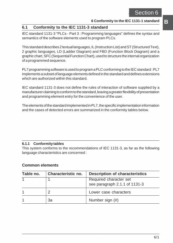
___________________________________________________________________________6/1
B
B
Conformity to the IEC 1131-1 standard 6Section 66 Conformity to the IEC 1131-1 standard
6.1 Conformity to the IEC 1131-3 standard
IEC standard 1131-3 "PLCs - Part 3 : Programming languages" defines the syntax andsemantics of the software elements used to program PLCs.
This standard describes 2 textual languages, IL (Instruction List) and ST (Structured Text),2 graphic languages, LD (Ladder Diagram) and FBD (Function Block Diagram) and agraphic chart, SFC (Sequential Function Chart), used to structure the internal organizationof a programmed sequence.
PL7 programming software is used to program a PLC conforming to the IEC standard : PL7implements a subset of language elements defined in the standard and defines extensionswhich are authorized within this standard.
IEC standard 1131-3 does not define the rules of interaction of software supplied by amanufacturer claiming to conform to the standard, leaving a greater flexibility of presentationand programming element entry for the convenience of the user.
The elements of the standard implemented in PL7, the specific implementation informationand the cases of detected errors are summarized in the conformity tables below.
6.1.1 Conformity tablesThis system conforms to the recommendations of IEC 1131-3, as far as the followinglanguage characteristics are concerned :
Common elements
Table no. Characteristic no. Description of characteristics1 1 Required character set
see paragraph 2.1.1 of 1131-3
1 2 Lower case characters
1 3a Number sign (#)
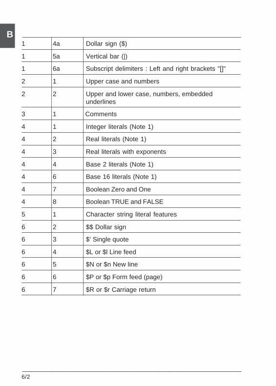
6/2___________________________________________________________________________
B1 4a Dollar sign ($)
1 5a Vertical bar (|)
1 6a Subscript delimiters : Left and right brackets "[]"
2 1 Upper case and numbers
2 2 Upper and lower case, numbers, embeddedunderlines
3 1 Comments
4 1 Integer literals (Note 1)
4 2 Real literals (Note 1)
4 3 Real literals with exponents
4 4 Base 2 literals (Note 1)
4 6 Base 16 literals (Note 1)
4 7 Boolean Zero and One
4 8 Boolean TRUE and FALSE
5 1 Character string literal features
6 2 $$ Dollar sign
6 3 $’ Single quote
6 4 $L or $l Line feed
6 5 $N or $n New line
6 6 $P or $p Form feed (page)
6 7 $R or $r Carriage return
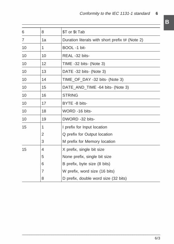
___________________________________________________________________________6/3
B
B
Conformity to the IEC 1131-1 standard 6
6 8 $T or $t Tab
7 1a Duration literals with short prefix t# (Note 2)
10 1 BOOL -1 bit-
10 10 REAL -32 bits-
10 12 TIME -32 bits- (Note 3)
10 13 DATE -32 bits- (Note 3)
10 14 TIME_OF_DAY -32 bits- (Note 3)
10 15 DATE_AND_TIME -64 bits- (Note 3)
10 16 STRING
10 17 BYTE -8 bits-
10 18 WORD -16 bits-
10 19 DWORD -32 bits-
15 1 I prefix for Input location
2 Q prefix for Output location
3 M prefix for Memory location
15 4 X prefix, single bit size
5 None prefix, single bit size
6 B prefix, byte size (8 bits)
7 W prefix, word size (16 bits)
8 D prefix, double word size (32 bits)
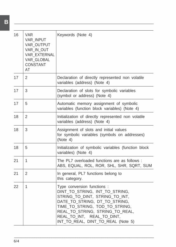
6/4___________________________________________________________________________
B
16 VAR Keywords (Note 4)VAR_INPUTVAR_OUTPUTVAR_IN_OUTVAR_EXTERNALVAR_GLOBALCONSTANTAT
17 2 Declaration of directly represented non volatilevariables (address) (Note 4)
17 3 Declaration of slots for symbolic variables(symbol or address) (Note 4)
17 5 Automatic memory assignment of symbolicvariables (function block variables) (Note 4)
18 2 Initialization of directly represented non volatilevariables (address) (Note 4)
18 3 Assignment of slots and initial valuesfor symbolic variables (symbols on addresses)(Note 4)
18 5 Initialization of symbolic variables (function blockvariables) (Note 4)
21 1 The PL7 overloaded functions are as follows :ABS, EQUAL, ROL, ROR, SHL, SHR, SQRT, SUM
21 2 In general, PL7 functions belong tothis category.
22 1 Type conversion functions :DINT_TO_STRING, INT_TO_STRING,STRING_TO_DINT, STRING_TO_INT,DATE_TO_STRING, DT_TO_STRING,TIME_TO_STRING, TOD_TO_STRING,REAL_TO_STRING, STRING_TO_REAL,REAL_TO_INT, REAL_TO_DINT,INT_TO_REAL, DINT_TO_REAL (Note 5)
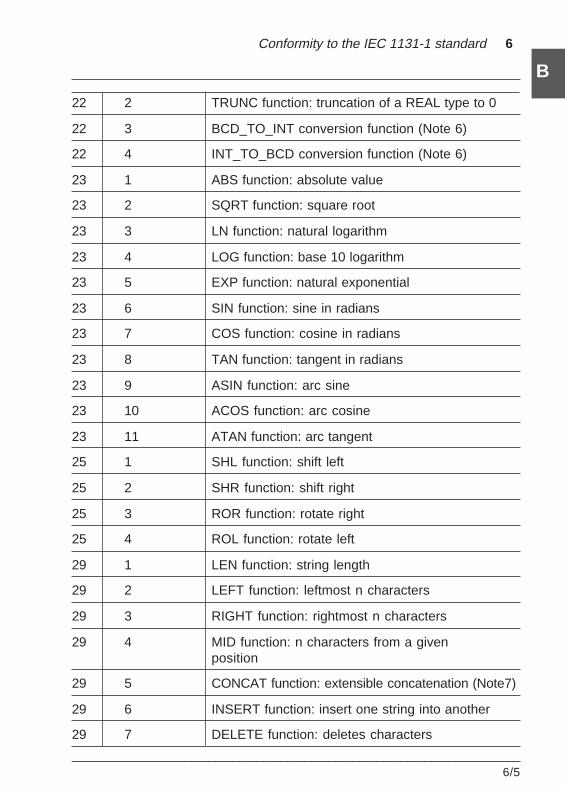
___________________________________________________________________________6/5
B
B
Conformity to the IEC 1131-1 standard 6
22 2 TRUNC function: truncation of a REAL type to 0
22 3 BCD_TO_INT conversion function (Note 6)
22 4 INT_TO_BCD conversion function (Note 6)
23 1 ABS function: absolute value
23 2 SQRT function: square root
23 3 LN function: natural logarithm
23 4 LOG function: base 10 logarithm
23 5 EXP function: natural exponential
23 6 SIN function: sine in radians
23 7 COS function: cosine in radians
23 8 TAN function: tangent in radians
23 9 ASIN function: arc sine
23 10 ACOS function: arc cosine
23 11 ATAN function: arc tangent
25 1 SHL function: shift left
25 2 SHR function: shift right
25 3 ROR function: rotate right
25 4 ROL function: rotate left
29 1 LEN function: string length
29 2 LEFT function: leftmost n characters
29 3 RIGHT function: rightmost n characters
29 4 MID function: n characters from a givenposition
29 5 CONCAT function: extensible concatenation (Note7)
29 6 INSERT function: insert one string into another
29 7 DELETE function: deletes characters
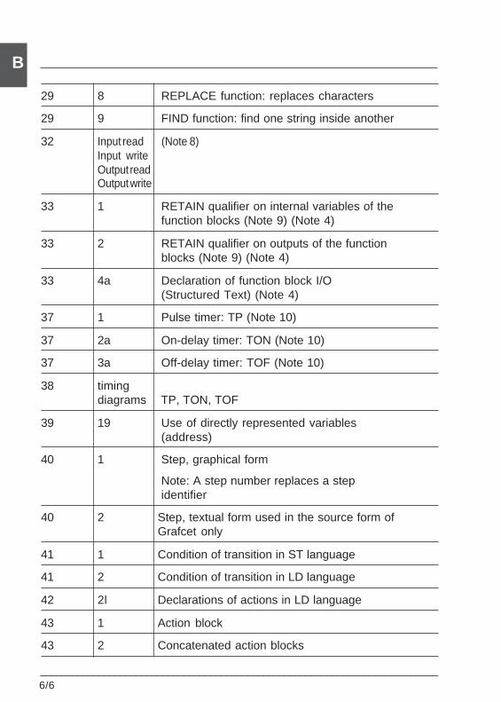
6/6___________________________________________________________________________
B
29 8 REPLACE function: replaces characters
29 9 FIND function: find one string inside another
32 Input read (Note 8)Input writeOutput readOutput write
33 1 RETAIN qualifier on internal variables of thefunction blocks (Note 9) (Note 4)
33 2 RETAIN qualifier on outputs of the functionblocks (Note 9) (Note 4)
33 4a Declaration of function block I/O(Structured Text) (Note 4)
37 1 Pulse timer: TP (Note 10)
37 2a On-delay timer: TON (Note 10)
37 3a Off-delay timer: TOF (Note 10)
38 timingdiagrams TP, TON, TOF
39 19 Use of directly represented variables(address)
40 1 Step, graphical form
Note: A step number replaces a stepidentifier
40 2 Step, textual form used in the source form ofGrafcet only
41 1 Condition of transition in ST language
41 2 Condition of transition in LD language
42 2l Declarations of actions in LD language
43 1 Action block
43 2 Concatenated action blocks
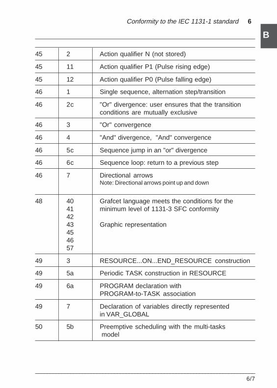
___________________________________________________________________________6/7
B
B
Conformity to the IEC 1131-1 standard 6
45 2 Action qualifier N (not stored)
45 11 Action qualifier P1 (Pulse rising edge)
45 12 Action qualifier P0 (Pulse falling edge)
46 1 Single sequence, alternation step/transition
46 2c "Or" divergence: user ensures that the transitionconditions are mutually exclusive
46 3 "Or" convergence
46 4 "And" divergence, "And" convergence
46 5c Sequence jump in an "or" divergence
46 6c Sequence loop: return to a previous step
46 7 Directional arrowsNote: Directional arrows point up and down
48 40 Grafcet language meets the conditions for the41 minimum level of 1131-3 SFC conformity4243 Graphic representation454657
49 3 RESOURCE...ON...END_RESOURCE construction
49 5a Periodic TASK construction in RESOURCE
49 6a PROGRAM declaration withPROGRAM-to-TASK association
49 7 Declaration of variables directly representedin VAR_GLOBAL
50 5b Preemptive scheduling with the multi-tasks model
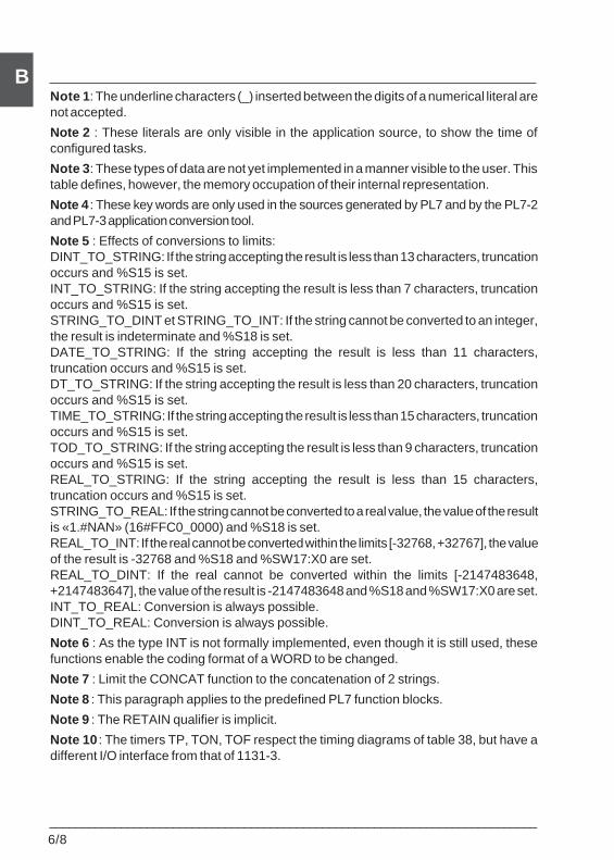
6/8___________________________________________________________________________
BNote 1 : The underline characters (_) inserted between the digits of a numerical literal arenot accepted.
Note 2 : These literals are only visible in the application source, to show the time ofconfigured tasks.
Note 3 : These types of data are not yet implemented in a manner visible to the user. Thistable defines, however, the memory occupation of their internal representation.
Note 4 : These key words are only used in the sources generated by PL7 and by the PL7-2and PL7-3 application conversion tool.
Note 5 : Effects of conversions to limits:DINT_TO_STRING: If the string accepting the result is less than 13 characters, truncationoccurs and %S15 is set.INT_TO_STRING: If the string accepting the result is less than 7 characters, truncationoccurs and %S15 is set.STRING_TO_DINT et STRING_TO_INT: If the string cannot be converted to an integer,the result is indeterminate and %S18 is set.DATE_TO_STRING: If the string accepting the result is less than 11 characters,truncation occurs and %S15 is set.DT_TO_STRING: If the string accepting the result is less than 20 characters, truncationoccurs and %S15 is set.TIME_TO_STRING: If the string accepting the result is less than 15 characters, truncationoccurs and %S15 is set.TOD_TO_STRING: If the string accepting the result is less than 9 characters, truncationoccurs and %S15 is set.REAL_TO_STRING: If the string accepting the result is less than 15 characters,truncation occurs and %S15 is set.STRING_TO_REAL: If the string cannot be converted to a real value, the value of the resultis «1.#NAN» (16#FFC0_0000) and %S18 is set.REAL_TO_INT: If the real cannot be converted within the limits [-32768, +32767], the valueof the result is -32768 and %S18 and %SW17:X0 are set.REAL_TO_DINT: If the real cannot be converted within the limits [-2147483648,+2147483647], the value of the result is -2147483648 and %S18 and %SW17:X0 are set.INT_TO_REAL: Conversion is always possible.DINT_TO_REAL: Conversion is always possible.
Note 6 : As the type INT is not formally implemented, even though it is still used, thesefunctions enable the coding format of a WORD to be changed.
Note 7 : Limit the CONCAT function to the concatenation of 2 strings.
Note 8 : This paragraph applies to the predefined PL7 function blocks.
Note 9 : The RETAIN qualifier is implicit.
Note 10 : The timers TP, TON, TOF respect the timing diagrams of table 38, but have adifferent I/O interface from that of 1131-3.
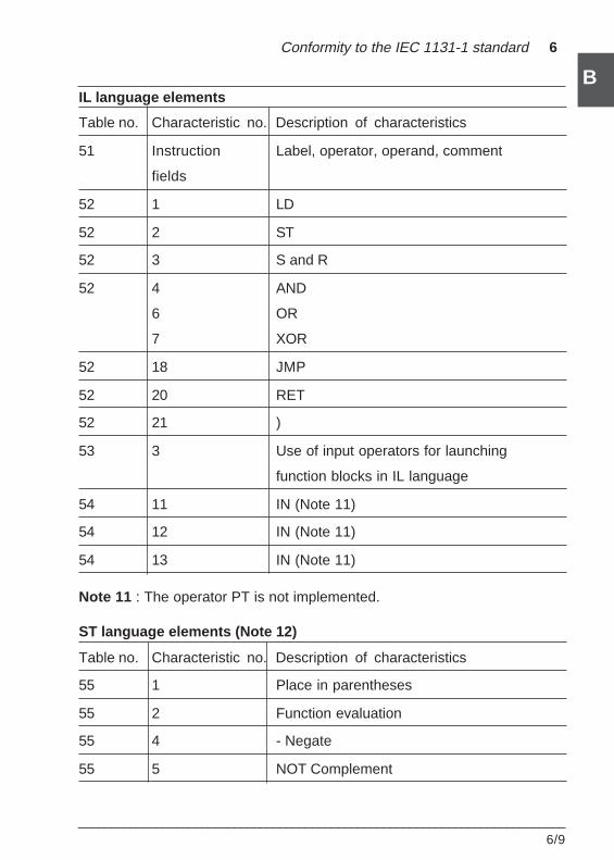
___________________________________________________________________________6/9
B
B
Conformity to the IEC 1131-1 standard 6
IL language elements
Table no. Characteristic no. Description of characteristics
51 Instruction Label, operator, operand, comment
fields
52 1 LD
52 2 ST
52 3 S and R
52 4 AND
6 OR
7 XOR
52 18 JMP
52 20 RET
52 21 )
53 3 Use of input operators for launching
function blocks in IL language
54 11 IN (Note 11)
54 12 IN (Note 11)
54 13 IN (Note 11)
Note 11 : The operator PT is not implemented.
ST language elements (Note 12)
Table no. Characteristic no. Description of characteristics
55 1 Place in parentheses
55 2 Function evaluation
55 4 - Negate
55 5 NOT Complement
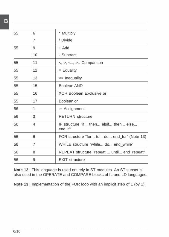
6/10___________________________________________________________________________
B
55 6 * Multiply
7 / Divide
55 9 + Add
10 - Subtract
55 11 <, >, <=, >= Comparison
55 12 = Equality
55 13 <> Inequality
55 15 Boolean AND
55 16 XOR Boolean Exclusive or
55 17 Boolean or
56 1 := Assignment
56 3 RETURN structure
56 4 IF structure "if... then... elsif... then... else...end_if"
56 6 FOR structure "for... to... do... end_for" (Note 13)
56 7 WHILE structure "while... do... end_while"
56 8 REPEAT structure "repeat ... until... end_repeat"
56 9 EXIT structure
Note 12 : This language is used entirely in ST modules. An ST subset isalso used in the OPERATE and COMPARE blocks of IL and LD languages.
Note 13 : Implementation of the FOR loop with an implicit step of 1 (by 1).
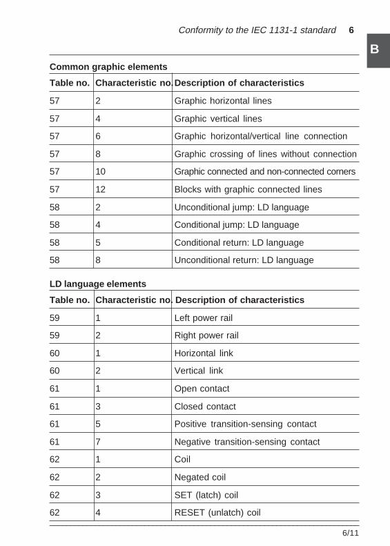
___________________________________________________________________________6/11
B
B
Conformity to the IEC 1131-1 standard 6
Common graphic elements
Table no. Characteristic no.Description of characteristics
57 2 Graphic horizontal lines
57 4 Graphic vertical lines
57 6 Graphic horizontal/vertical line connection
57 8 Graphic crossing of lines without connection
57 10 Graphic connected and non-connected corners
57 12 Blocks with graphic connected lines
58 2 Unconditional jump: LD language
58 4 Conditional jump: LD language
58 5 Conditional return: LD language
58 8 Unconditional return: LD language
LD language elements
Table no. Characteristic no. Description of characteristics
59 1 Left power rail
59 2 Right power rail
60 1 Horizontal link
60 2 Vertical link
61 1 Open contact
61 3 Closed contact
61 5 Positive transition-sensing contact
61 7 Negative transition-sensing contact
62 1 Coil
62 2 Negated coil
62 3 SET (latch) coil
62 4 RESET (unlatch) coil
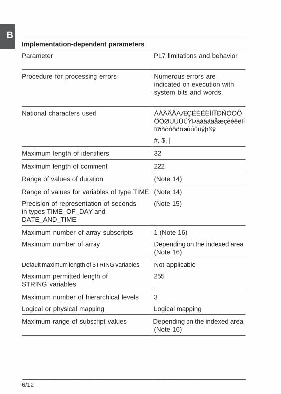
6/12___________________________________________________________________________
BImplementation-dependent parameters
Parameter PL7 limitations and behavior
Procedure for processing errors Numerous errors areindicated on execution withsystem bits and words.
National characters used ÀÁÂÃÄÅÆÇÈÉÊËÌÍÎÏÐÑÒÓÔÕÖØÙÚÛÜÝÞàáâãäåæçèéêëìíîïðñòóôõöøùúûüýþßÿ
#, $, |
Maximum length of identifiers 32
Maximum length of comment 222
Range of values of duration (Note 14)
Range of values for variables of type TIME (Note 14)
Precision of representation of seconds (Note 15)in types TIME_OF_DAY andDATE_AND_TIME
Maximum number of array subscripts 1 (Note 16)
Maximum number of array Depending on the indexed area(Note 16)
Default maximum length of STRING variables Not applicable
Maximum permitted length of 255STRING variables
Maximum number of hierarchical levels 3
Logical or physical mapping Logical mapping
Maximum range of subscript values Depending on the indexed area(Note 16)
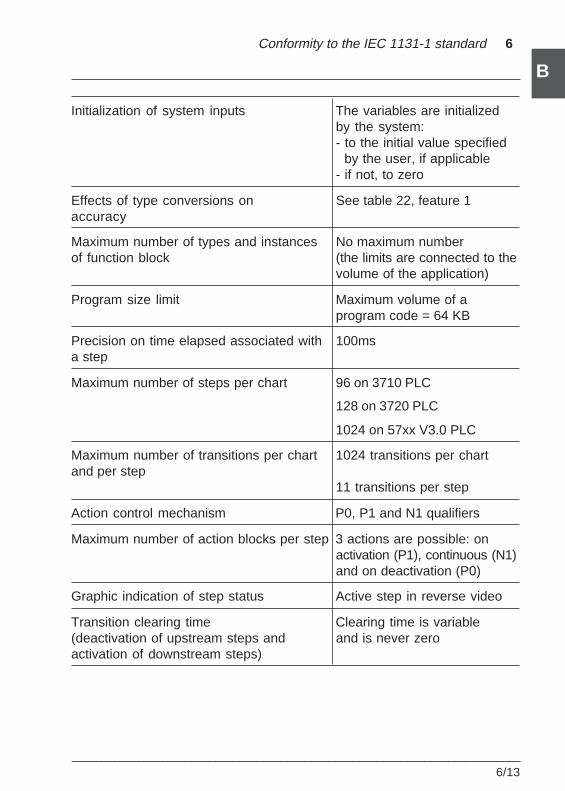
___________________________________________________________________________6/13
B
B
Conformity to the IEC 1131-1 standard 6
Initialization of system inputs The variables are initializedby the system:- to the initial value specified by the user, if applicable- if not, to zero
Effects of type conversions on See table 22, feature 1accuracy
Maximum number of types and instances No maximum numberof function block (the limits are connected to the
volume of the application)
Program size limit Maximum volume of aprogram code = 64 KB
Precision on time elapsed associated with 100msa step
Maximum number of steps per chart 96 on 3710 PLC
128 on 3720 PLC
1024 on 57xx V3.0 PLC
Maximum number of transitions per chart 1024 transitions per chartand per step
11 transitions per step
Action control mechanism P0, P1 and N1 qualifiers
Maximum number of action blocks per step 3 actions are possible: onactivation (P1), continuous (N1)and on deactivation (P0)
Graphic indication of step status Active step in reverse video
Transition clearing time Clearing time is variable(deactivation of upstream steps and and is never zeroactivation of downstream steps)
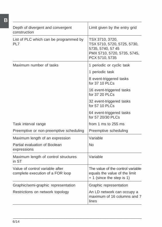
6/14___________________________________________________________________________
BDepth of divergent and convergent Limit given by the entry gridconstruction
List of PLC which can be programmed by TSX 3710, 3720,PL7 TSX 5710, 5720, 5725, 5730,
5735, 5740, 57 45PMX 5710, 5720, 5735, 5745,PCX 5710, 5735
Maximum number of tasks 1 periodic or cyclic task
1 periodic task
8 event-triggered tasksfor 37 10 PLCs
16 event-triggered tasksfor 37 20 PLCs
32 event-triggered tasksfor 57 10 PLCs
64 event-triggered tasksfor 57 20/30 PLCs
Task interval range from 1 ms to 255 ms
Preemptive or non-preemptive scheduling Preemptive scheduling
Maximum length of an expression Variable
Partial evaluation of Boolean Noexpressions
Maximum length of control structures Variablein ST
Value of control variable after The value of the control variablecomplete execution of a FOR loop equals the value of the limit
+ 1 (since the step is 1)
Graphic/semi-graphic representation Graphic representation
Restrictions on network topology An LD network can occupy amaximum of 16 columns and 7lines
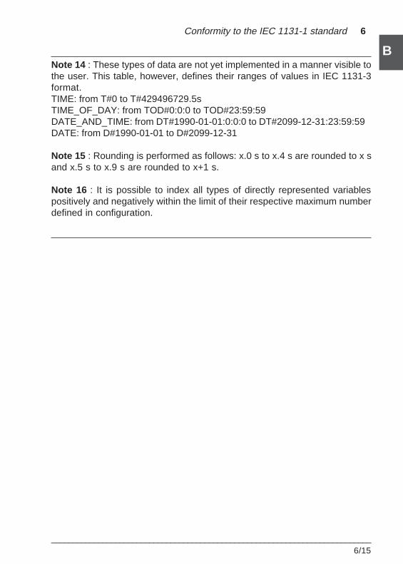
___________________________________________________________________________6/15
B
B
Conformity to the IEC 1131-1 standard 6
Note 14 : These types of data are not yet implemented in a manner visible tothe user. This table, however, defines their ranges of values in IEC 1131-3format.TIME: from T#0 to T#429496729.5sTIME_OF_DAY: from TOD#0:0:0 to TOD#23:59:59DATE_AND_TIME: from DT#1990-01-01:0:0:0 to DT#2099-12-31:23:59:59DATE: from D#1990-01-01 to D#2099-12-31
Note 15 : Rounding is performed as follows: x.0 s to x.4 s are rounded to x sand x.5 s to x.9 s are rounded to x+1 s.
Note 16 : It is possible to index all types of directly represented variablespositively and negatively within the limit of their respective maximum numberdefined in configuration.

6/16___________________________________________________________________________
B
Error conditions
Error conditions PL7 limits and behavior
Type conversion errors Indicated during the executionwith a system bit: Seetable Common elements:table 22, feature 1
Numerical result exceeds range for Indicated during the executiondata type with system bit %S18
Invalid character position specified Indicated during the executionwith system bit %S18
Result exceeds maximum string length Indicated during the executionwith system bit %S15
Overflow errors during evaluation of a Detected during programmingtransition
Execution deadlines not met Indicated on executionwith system bit %S19
Other task scheduling conflicts Detected during configuration
Division by zero Detected during programmingif possible, otherwise indicated
Type of data invalid for an operation on execution with system bit%S18
Failure of a FOR or WHILE iteration The PLC goes to watchdogto finish overflow fault and the CPU
involved is indicated
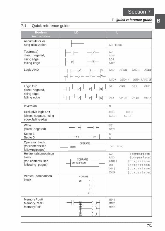
Quick reference guide 7
___________________________________________________________________________7/1
B
B
P N
P N
P N
P N
P N
( ) ( / )
( S ) ( R )
OPERATEaction
COMPAREcomparaison
>
=
<
<>
EN
COMPARE
Section 77 Quick reference guide
7.1 Quick reference guide
Boolean LD ILinstructions
Accumulator orrung initialization LD TRUE
Test (read) LDdirect, negated, LDNrising edge, LDRfalling edge LDF
Logic AND AND ANDN ANDR ANDF
AND( AND(N AND(RAND(F
Logic OR OR ORN ORR ORFdirect, negated,rising edge,falling edge OR( OR(N OR(R OR(F
Inversion N
Exclusive logic OR XOR XORN(direct, negated, rising XORR XORFedge, falling edge
Write ST(direct, negated) STN
Set to 1 SSet to 0 R
Operation block(for contents see [action]following pages)Horizontal comparison LD [comparison]block AND [comparison](for contents see AND( [comparison]following pages) OR [comparison]
OR( [comparison]XOR [comparison]
Vertical comparisonblock
Memory PusH MPSMemory ReaD MRDMemory PoP MPP
comparison
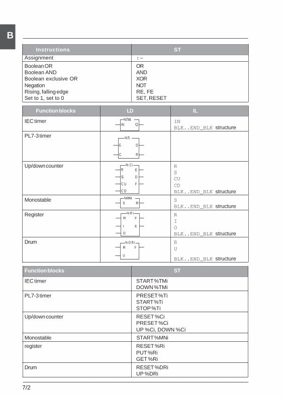
7/2___________________________________________________________________________
Bb
Instructions ST
Assignment :=
Boolean OR ORBoolean AND ANDBoolean exclusive OR XORNegation NOTRising, falling edge RE, FESet to 1, set to 0 SET, RESET
Function blocks LD IL
IEC timer INBLK..END_BLK structure
PL7-3 timer
Up/down counter RSCUCDBLK..END_BLK structure
Monostable SBLK..END_BLK structure
Register RIOBLK..END_BLK structure
Drum RU
BLK..END_BLK structure
Function blocks ST
IEC timer START %TMiDOWN %TMi
PL7-3 timer PRESET %TiSTART %TiSTOP %Ti
Up/down counter RESET %CiPRESET %CiUP %Ci, DOWN %Ci
Monostable START %MNi
register RESET %RiPUT %RiGET %Ri
Drum RESET %DRiUP %DRi
IN Q%TMi
E
C
D
R
%Ti
E
C D
D
C U
% C i
F
R
S
S R%MNi
F
I E
R% R i
O
F
U
R% D R i
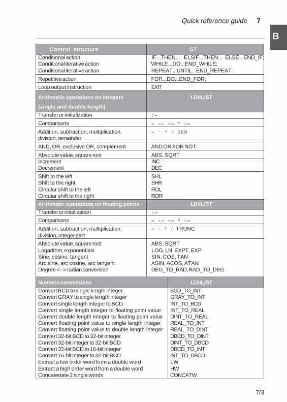
Quick reference guide 7
___________________________________________________________________________7/3
B
BControl structure ST
Conditional action IF...THEN... ELSIF...THEN... ELSE...END_IF;Conditional iterative action WHILE...DO...END_WHILE;Conditional iterative action REPEAT...UNTIL...END_REPEAT;
Repetitive action FOR...DO...END_FOR;
Loop output instruction EXIT
Arithmetic operations on integers LD/IL/ST
(single and double length)
Transfer or initialization :=
Comparisons = <> <= “ >=
Addition, subtraction, multiplication, + - * / REMdivision, remainder
AND, OR, exclusive OR, complement AND OR XOR NOT
Absolute value, square root ABS, SQRTIncrement INCDecrement DEC
Shift to the left SHLShift to the right SHRCircular shift to the left ROLCircular shift to the right ROR
Arithmetic operations on floating points LD/IL/ST
Transfer or intialization :=
Comparisons = <> <= “ >=
Addition, subtraction, multiplication, + - * / TRUNCdivision, integer part
Absolute value, square root ABS, SQRTLogarithm, exponentials LOG, LN, EXPT, EXPSine, cosine, tangent SIN, COS, TANArc sine, arc cosine, arc tangent ASIN, ACOS, ATANDegree <--> radian conversion DEG_TO_RAD, RAD_TO_DEG
Numeric conversions LD/IL/ST
Convert BCD to single length integer BCD_TO_INTConvert GRAY to single length integer GRAY_TO_INTConvert single length integer to BCD INT_TO_BCDConvert single length integer to floating point value INT_TO_REALConvert double length integer to floating point value DINT_TO_REALConvert floating point value to single length integer REAL_TO_INTConvert floating point value to double length integer REAL_TO_DINTConvert 32-bit BCD to 32-bit integer DBCD_TO_DINTConvert 32-bit integer to 32-bit BCD DINT_TO_DBCDConvert 32-bit BCD to 16-bit integer DBCD_TO_INTConvert 16-bit integer to 32-bit BCD INT_TO_DBCDExtract a low order word from a double word LWExtract a high order word from a double word HWConcatenate 2 single words CONCATW
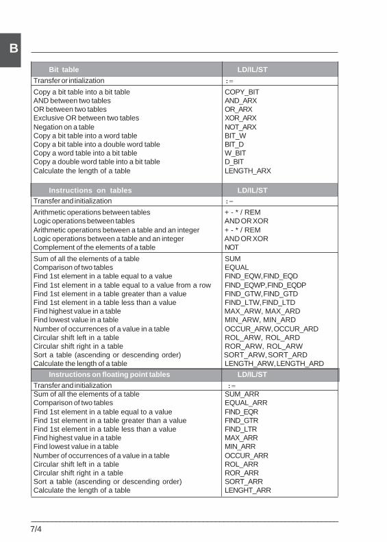
7/4___________________________________________________________________________
B
Bit table LD/IL/ST
Transfer or intialization :=
Copy a bit table into a bit table COPY_BITAND between two tables AND_ARXOR between two tables OR_ARXExclusive OR between two tables XOR_ARXNegation on a table NOT_ARXCopy a bit table into a word table BIT_WCopy a bit table into a double word table BIT_DCopy a word table into a bit table W_BITCopy a double word table into a bit table D_BITCalculate the length of a table LENGTH_ARX
Instructions on tables LD/IL/STTransfer and initialization :=
Arithmetic operations between tables + - * / REMLogic operations between tables AND OR XORArithmetic operations between a table and an integer + - * / REMLogic operations between a table and an integer AND OR XORComplement of the elements of a table NOT
Sum of all the elements of a table SUMComparison of two tables EQUALFind 1st element in a table equal to a value FIND_EQW, FIND_EQDFind 1st element in a table equal to a value from a row FIND_EQWP, FIND_EQDPFind 1st element in a table greater than a value FIND_GTW, FIND_GTDFind 1st element in a table less than a value FIND_LTW, FIND_LTDFind highest value in a table MAX_ARW, MAX_ARDFind lowest value in a table MIN_ARW, MIN_ARDNumber of occurrences of a value in a table OCCUR_ARW, OCCUR_ARDCircular shift left in a table ROL_ARW, ROL_ARDCircular shift right in a table ROR_ARW, ROL_ARWSort a table (ascending or descending order) SORT_ARW, SORT_ARDCalculate the length of a table LENGTH_ARW, LENGTH_ARD
Instructions on floating point tables LD/IL/ST
Transfer and initialization :=Sum of all the elements of a table SUM_ARRComparison of two tables EQUAL_ARRFind 1st element in a table equal to a value FIND_EQRFind 1st element in a table greater than a value FIND_GTRFind 1st element in a table less than a value FIND_LTRFind highest value in a table MAX_ARRFind lowest value in a table MIN_ARRNumber of occurrences of a value in a table OCCUR_ARRCircular shift left in a table ROL_ARRCircular shift right in a table ROR_ARRSort a table (ascending or descending order) SORT_ARRCalculate the length of a table LENGHT_ARR
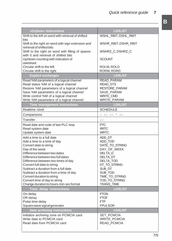
Quick reference guide 7
___________________________________________________________________________7/5
B
B
«Orphee» instructions LD/IL/ST
Shift to the left on word with retrieval of shifted WSHL_RBIT, DSHL_RBITbitsShift to the right on word with sign extension and WSHR_RBIT, DSHR_RBITretrieval of shifted bitsShift to the right on word with filling of spaces WSHRZ_C, DSHRZ_Cwith 0 and retrieval of shifted bitsUp/down counting with indication of SCOUNTovershootCircular shift to the left ROLW, ROLDCircular shift to the right RORW, RORD
Explicit exchanges LD/IL/ST
Read %M parameters of a logical channel READ_PARAMRead status %M of a logical channel READ_STSRestore %M parameters of a logical channel RESTORE_PARAMSave %M parameters of a logical channel SAVE_PARAMWrite control %M of a logical channel WRITE_CMDWrite %M parameters of a logical channel WRITE_PARAM
Time management instructions LD/IL/ST
Realtime clock SCHEDULE
Comparisons = <> <= “ >=
Transfer :=
Read date and code of last PLC stop PTCRead system date RRTCUpdate system date WRTC
Add a time to a full date ADD_DTAdd a time to a time of day ADD_TODConvert date to string DATE_TO_STRINGDay of the week DAY_OF_WEEKDifference between two dates DELTA_DDifference between two full dates DELTA_DTDifference between two times of day DELTA_TODConvert full date to string DT_TO_STRINGSubtract a duration from a full date SUB_DTSubtract a duration from a time of day SUB_TODConvert duration to string TIME_TO_STRINGConvert time of day to string TOD_TO_STRINGChange duration to hours-min-sec format TRANS_TIME
Time delay instructions LD/IL/ST
On-delay FTONOff-delay FTOFPulse time delay FTPSquare wave signal generator FPULSOR
Data archiving instructions LD/IL/ST
Initialize archiving zone on PCMCIA card SET_PCMCIAWrite data to PCMCIA card WRITE_PCMCIARead data from PCMCIA card READ_PCMCIA
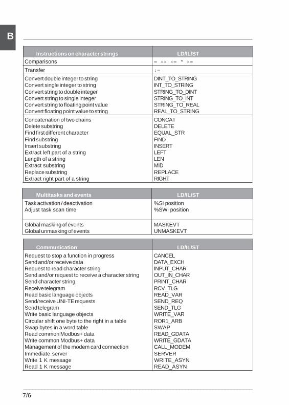
7/6___________________________________________________________________________
B
Instructions on character strings LD/IL/STComparisons = <> <= “ >=
Transfer :=
Convert double integer to string DINT_TO_STRINGConvert single integer to string INT_TO_STRINGConvert string to double integer STRING_TO_DINTConvert string to single integer STRING_TO_INTConvert string to floating point value STRING_TO_REALConvert floating point value to string REAL_TO_STRING
Concatenation of two chains CONCATDelete substring DELETEFind first different character EQUAL_STRFind substring FINDInsert substring INSERTExtract left part of a string LEFTLength of a string LENExtract substring MIDReplace substring REPLACEExtract right part of a string RIGHT
Multitasks and events LD/IL/ST
Task activation / deactivation %Si positionAdjust task scan time %SWi position
Global masking of events MASKEVTGlobal unmasking of events UNMASKEVT
Communication LD/IL/ST
Request to stop a function in progress CANCELSend and/or receive data DATA_EXCHRequest to read character string INPUT_CHARSend and/or request to receive a character string OUT_IN_CHARSend character string PRINT_CHARReceive telegram RCV_TLGRead basic language objects READ_VARSend/receive UNI-TE requests SEND_REQSend telegram SEND_TLGWrite basic language objects WRITE_VARCircular shift one byte to the right in a table ROR1_ARBSwap bytes in a word table SWAPRead common Modbus+ data READ_GDATAWrite common Modbus+ data WRITE_GDATAManagement of the modem card connection CALL_MODEMImmediate server SERVERWrite 1 K message WRITE_ASYNRead 1 K message READ_ASYN
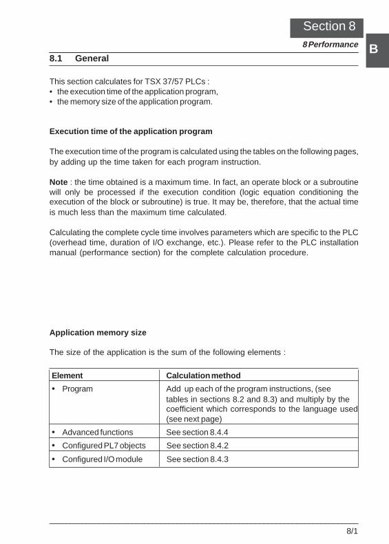
___________________________________________________________________________8/1
B
B
Performance 8Section 88 Performance
8.1 General
This section calculates for TSX 37/57 PLCs :• the execution time of the application program,• the memory size of the application program.
Execution time of the application program
The execution time of the program is calculated using the tables on the following pages,by adding up the time taken for each program instruction.
Note : the time obtained is a maximum time. In fact, an operate block or a subroutinewill only be processed if the execution condition (logic equation conditioning theexecution of the block or subroutine) is true. It may be, therefore, that the actual timeis much less than the maximum time calculated.
Calculating the complete cycle time involves parameters which are specific to the PLC(overhead time, duration of I/O exchange, etc.). Please refer to the PLC installationmanual (performance section) for the complete calculation procedure.
Application memory size
The size of the application is the sum of the following elements :
Element Calculation method
• Program Add up each of the program instructions, (seetables in sections 8.2 and 8.3) and multiply by thecoefficient which corresponds to the language used(see next page)
• Advanced functions See section 8.4.4
• Configured PL7 objects See section 8.4.2
• Configured I/O module See section 8.4.3
8/2___________________________________________________________________________
BIn the tables on the following pages, information on sizes refers to the volume ofinstruction codes. In order to find out the total size of an instruction or a program, it isnecessary to use a multiplication coefficient which takes account of information that istypical to a language (for example : graphic information in the case of Ladder language).
• Ladder language : Total volume = 1.7 x Code volume
• Structured Text language : Total volume = 1.6 x Code volume
• Instruction List language :- for TSX37 PLCs : Total volume = 1.4 x Code volume- for TSX57 PLCs : Total volume = 1.6 x Code volume
• Grafcet language :The volume associated with the chart itself is as follows :Chart volume (in words) = 214 + 17 * no. of chart steps + 2 * total no. of configuredsteps + 4 * no. of programmed actions
Note : program comments occupy 1 byte per character.
Comment
The figures shown in the following tables are average estimations obtained from atypical application. It is not possible to provide exact data, since PL7 optimizesmemory use according to the contents and structure of the application.
Section 8.4.1 describes the various memory zones occupied by the application.
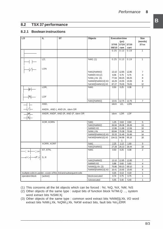
___________________________________________________________________________8/3
B
B
Performance 8
8.2 TSX 37 performance
8.2.1 Boolean instructions
LD IL ST Objects Execution time Size(µs) (words)
3705 3720 3720 37xx08/10 ram cart0.25 0.13 0.19 1
LD, %M1 (1) 0.25 0.13 0.19 1
LDN%M1[%MW2] 13.10 12.85 12.85 7%MW0:X0 (2) 6.06 5.75 5.75 4%IWi.j:Xk (3) 77.04 69.25 69.25 8%MW0[%MW10]:X0 16.29 15.55 15.55 8%KW0[%MW10]:X0 87.27 79.05 79.05 12
LDR, %M1 0.50 0.25 0.38 2
LDF
%M1[%MW2] 13.01 12.75 12.75 7AND, idem LD, LDN
ANDN , AND (, AND (N , idem OR
ANDR, ANDF, AND (R, AND (F, idem OR idem LDR LDF
XOR, XORN %M1 1.25 0.63 0.94 5%M1[%MW2] 26.94 26.08 26.26 13%MW0:X0 12.86 11.88 12.06 10%IWi.j:Xk 83.84 75.38 75.56 14%MW0[%MW10]:X0 33.33 31.48 31.66 14%KW0[%MW10]:X0 104.31 94.98 95.16 18
1XORR, XORF %M1 2.25 1.13 1.69 9
%M1[%MW2] 27.28 26.13 26.44 19ST, STN, %M1 0.50 0.25 0.38 2
S, R%M1[%MW2] 13.10 12.85 12.85 7%MW0:X0 5.88 5.60 5.60 4%NW{i}j:Xk (3) 76.86 69.10 69.10 8%MW0[%MW10]:X0 16.41 15.65 15.65 8
multiple coils in Ladder, «cost» of the 2nd and subsequent coils 0.25 0.13 0.19 1operation block [ action] block executed 0.74 0.75 0.75 1
not executed 5.55 5.40 5.40 1
(1) This concerns all the bit objects which can be forced : %I, %Q, %X, %M, %S(2) Other objects of the same type : output bits of function block %TMi.Q ..., system
word extract bits %SWi:Xj(3) Other objects of the same type : common word extract bits %NW{i}j:Xk, I/O word
extract bits %IWi.j.Xk, %QWi.j.Xk, %KW extract bits, fault bits %Ii.j.ERR
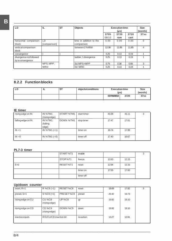
8/4___________________________________________________________________________
BLD IL ST Objects Execution time Size
(µs) (words)3705 3720 3720 37xx08/10 ram cart
horizontal comparison LD time in addition to the 0.00 0.00 0.00 0block [comparison] comparisonvertical comparison between 2 %MWi 12.38 11.85 11.85 4blockconvergence ) ) 0.25 0.13 0.19 1divergence not followed ladder, 1 divergence 0.25 0.13 0.19 1by a convergence
MPS, MPP, list MPS+MPP 0.75 0.38 0.56 3MRD list MRD 0.25 0.13 0.19 1
8.2.2 Function blocks
LD IL ST objects/conditions Execution time Size (µs) (words)
03705/08/10 3720 37xx
IE timerrising edge on IN IN %TM1 START %TM1 start timer 43.39 41.11 3
(rising edge)falling edge on IN IN %TM1 DOWN %TM1 stop timer 17.47 17.01
(fallingedge)
IN =1 IN %TM1 (=1) timer on 18.74 17.99
IN =0 IN %TM1 (=0) timer off 17.40 16.67
PL7-3 timerSTART %T1 enable 3
STOP %T1 freeze 12.63 12.15
E=0 RESET %T1 reset 12.94 12.15
timer on 17.55 17.00
timer off
Up/down counterreset, R=1 R %C8 (=1) RESET %C8 reset 18.69 17.92 3
preset, S=1 S %C9 (=1) PRESET %C9 preset 20.42 19.73
rising edge on CU CU %C8 UP %C8 up 19.92 19.10(rising edge)
rising edge on CD CD %C9 DOWN %C9 down 19.92 19.10(rising edge)
inactive inputs R/S/CU/CD inactive bit no action 13.27 12.81
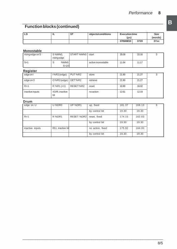
___________________________________________________________________________8/5
B
B
Performance 8
Function blocks (continued)
LD IL ST objects/conditions Execution time Size(µs) (words)
3705/08/10 3720 37xx
Monostablerising edge on S S %MN0, START %MN0 start 35.08 33.16 3
rising edge
S=1 S %MN0, active monostable 11.64 11.17S=1/0
Registeredge on I I %R2 (edge) PUT %R2 store 21.90 21.27 3
edge on O O %R2 (edge) GET %R2 retrieve 21.90 21.27
R=1 R %R1 (=1) RESET %R2 reset 16.90 16.02
inactive inputs I/O/R, inactive no action 12.61 12.19bit
Drumedge on U U %DR0 UP %DR1 up, fixed 181.37 169.13 3
by control bit 19.30 19.30
R=1 R %DR1 RESET %DR2 reset, fixed 174.15 162.03
by control bit 19.30 19.30
inactive inputs R/U, inactive bit no action, fixed 175.92 164.00
by control bit 19.30 19.30
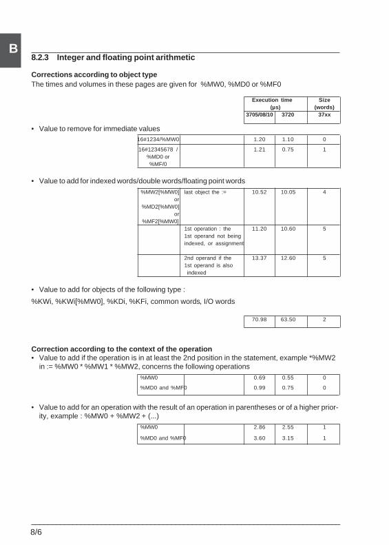
8/6___________________________________________________________________________
B8.2.3 Integer and floating point arithmetic
Corrections according to object typeThe times and volumes in these pages are given for %MW0, %MD0 or %MF0
Execution time Size(µs) (words)
3705/08/10 3720 37xx
• Value to remove for immediate values16#1234/%MW0 1.20 1.10 0
16#12345678 / 1.21 0.75 1%MD0 or%MF/0
• Value to add for indexed words/double words/floating point words%MW2[%MW0] last object the := 10.52 10.05 4
or%MD2[%MW0]
or%MF2[%MW0]
1st operation : the 11.20 10.60 51st operand not beingindexed, or assignment
2nd operand if the 13.37 12.60 51st operand is also indexed
• Value to add for objects of the following type :
%KWi, %KWi[%MW0], %KDi, %KFi, common words, I/O words
70.98 63.50 2
Correction according to the context of the operation• Value to add if the operation is in at least the 2nd position in the statement, example *%MW2
in := %MW0 * %MW1 * %MW2, concerns the following operations%MW0 0.69 0.55 0
%MD0 and %MF0 0.99 0.75 0
• Value to add for an operation with the result of an operation in parentheses or of a higher prior-ity, example : %MW0 + %MW2 + (...)
%MW0 2.86 2.55 1
%MD0 and %MF0 3.60 3.15 1
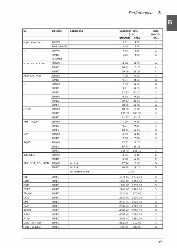
___________________________________________________________________________8/7
B
B
Performance 8
ST Objects Conditions Execution time Size(µs) (words)
3705/08/10 3720 37xx
object after the := %MW0 4.81 4.50 2
%MD0,%MF0 6.45 5.70 2
:= %MW0 4.46 4.30 2
%MD0 5.15 4.85 2
et %MF0
=, <>, <=, <, >, >= %MW0 8.94 8.50 4
%MD0 10.71 10.26 4
%MF0 29.06 28.39 4
AND, OR, XOR %MW0 7.29 6.90 3
%MD0 9.21 8.55 3
+, - %MW0 7.29 6.90 3
%MD0 9.21 8.55 3
%MF0 62.83 61.20 3
* %MW0 9.75 9.10 3
%MD0 39.63 36.50 3
%MF0 58.26 56.90 3
/, REM %MW0 10.69 10.08 3
%MD0 205.21 201.38 3
/ %MF0 62.47 60.25 3
ABS, -object %MW0 7.20 6.95 3
%MD0 9.97 9.53 3
%MF0 13.01 12.50 3
NOT %MW0 6.69 6.45 3
%MD0 7.80 7.40 3
SQRT %MW0 17.02 16.70 3
%MD0 85.73 85.25 3
%MF0 165.04 158.40 3
INC, DEC %MW0 4.86 4.40 2
%MD0 5.20 4.75 2
SHL, SHR, ROL, ROR %MW0 for 1 bit 17.74 17.05 5
%MD0 for 1 bit 20.58 19.15 5
per additional bit 0.063
LN %MF0 1371.60 1270.00 3
LOG %MF0 1458.00 1350.00 3
EXP %MF0 1155.60 1070.00 3
EXPT %MF0 2988.00 2490.00 3
TRUNC %MF0 204.00 170.00 3
COS %MF0 2829.60 2620.00 3
SIN %MF0 2840.40 2630.00 3
TAN %MF0 2937.60 2720.00 3
ACOS %MF0 4082.40 3780.00 3
ASIN %MF0 4082.40 3780.00 3
ATAN %MF0 2786.40 2580.00 3
DEG_TO_RAD %MF0 852.00 710.00 3
RAD_TO_DEG %MF0 720.00 600.00 3
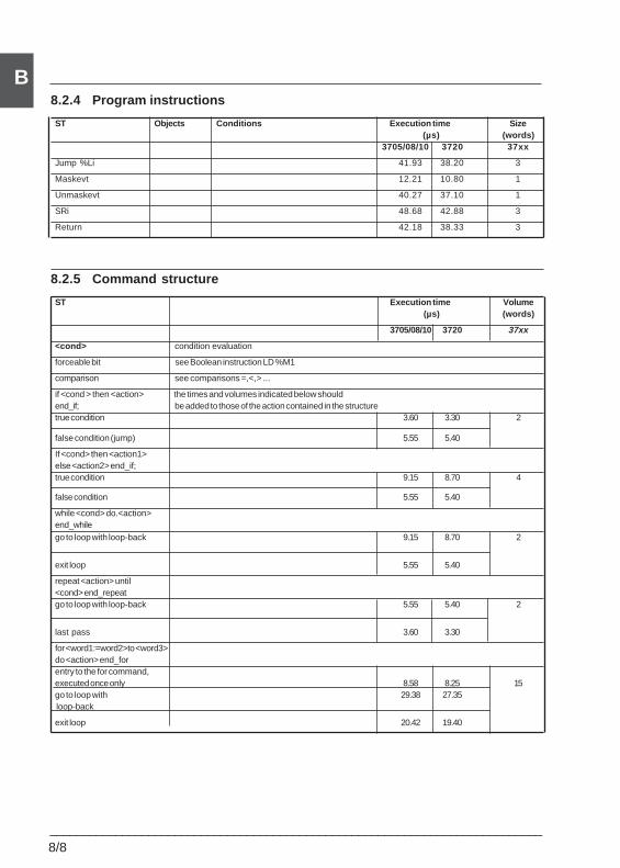
8/8___________________________________________________________________________
B8.2.4 Program instructions
ST Objects Conditions Execution time Size(µs) (words)
3705/08/10 3720 37xx
Jump %Li 41.93 38.20 3
Maskevt 12.21 10.80 1
Unmaskevt 40.27 37.10 1
SRi 48.68 42.88 3
Return 42.18 38.33 3
8.2.5 Command structure
ST Execution time Volume(µs) (words)
3705/08/10 3720 37xx
<cond> condition evaluation
forceable bit see Boolean instruction LD %M1
comparison see comparisons =,<,> ...
if <cond > then <action> the times and volumes indicated below shouldend_if; be added to those of the action contained in the structuretrue condition 3.60 3.30 2
false condition (jump) 5.55 5.40
If <cond> then <action1>else <action2> end_if;true condition 9.15 8.70 4
false condition 5.55 5.40
while <cond> do.<action>end_whilego to loop with loop-back 9.15 8.70 2
exit loop 5.55 5.40
repeat <action> until<cond> end_repeatgo to loop with loop-back 5.55 5.40 2
last pass 3.60 3.30
for <word1:=word2>to <word3>do <action> end_forentry to the for command,executed once only 8.58 8.25 15go to loop with 29.38 27.35 loop-back
exit loop 20.42 19.40
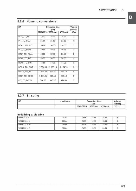
___________________________________________________________________________8/9
B
B
Performance 8
8.2.6 Numeric conversions
ST Execution time Volume(µs) (words)
3705/08/10 3720 ram 3720 cart 37xx
BCD_TO_INT 25.03 24.55 24.55 3
INT_TO_BCD 21.66 21.15 21.15 3
GRAY_TO_INT 36.98 36.55 36.55 3
INT_TO_REAL 40.90 40.75 40.75 3
DINT_TO_REAL 33.32 32.55 32.55 3
REAL_TO_INT 58.75 58.55 58.55 3
REAL_TO_DINT 44.59 44.05 44.05 3
DBCD_TO_DINT 1 324.85 1 065.15 1 134.70 5
DBCD_TO_INT 1 265.54 925.70 986.15 5
DINT_TO_DBCD 1 124.85 825.15 879.10 5
INT_TO_DBCD 564.85 445.15 474.40 5
8.2.7 Bit string
ST conditions Execution time Volume(µs) (words)
3705/08/10 3720 ram 3720 cart 37xx
Initializing a bit table%M30:8 := 0 8 bits 19.38 18.88 18.88 6
%M30:16 := 1 16 bits 20.38 19.88 19.88 6
%M30:24 := 2 24 bits 24.25 23.35 23.35 6
%M30:32 := 2 32 bits 25.25 24.35 24.35 6
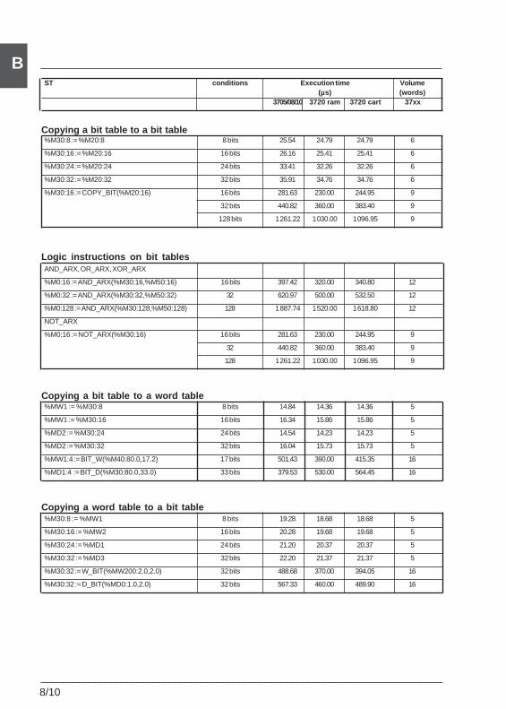
8/10___________________________________________________________________________
BST conditions Execution time Volume
(µs) (words)3705/08/10 3720 ram 3720 cart 37xx
Copying a bit table to a bit table%M30:8 := %M20:8 8 bits 25.54 24.79 24.79 6
%M30:16 := %M20:16 16 bits 26.16 25.41 25.41 6
%M30:24 := %M20:24 24 bits 33.41 32.26 32.26 6
%M30:32 := %M20:32 32 bits 35.91 34.76 34.76 6
%M30:16 := COPY_BIT(%M20:16) 16 bits 281.63 230.00 244.95 9
32 bits 440.82 360.00 383.40 9
128 bits 1 261.22 1 030.00 1 096.95 9
Logic instructions on bit tablesAND_ARX, OR_ARX, XOR_ARX
%M0:16 := AND_ARX(%M30:16,%M50:16) 16 bits 397.42 320.00 340.80 12
%M0:32 := AND_ARX(%M30:32,%M50:32) 32 620.97 500.00 532.50 12
%M0:128 := AND_ARX(%M30:128,%M50:128) 128 1 887.74 1 520.00 1 618.80 12
NOT_ARX
%M0:16 := NOT_ARX(%M30:16) 16 bits 281.63 230.00 244.95 9
32 440.82 360.00 383.40 9
128 1 261.22 1 030.00 1 096.95 9
Copying a bit table to a word table%MW1 := %M30:8 8 bits 14.84 14.36 14.36 5
%MW1 := %M30:16 16 bits 16.34 15.86 15.86 5
%MD2 := %M30:24 24 bits 14.54 14.23 14.23 5
%MD2 := %M30:32 32 bits 16.04 15.73 15.73 5
%MW1:4 := BIT_W(%M40:80.0,17.2) 17 bits 501.43 390.00 415.35 16
%MD1:4 := BIT_D(%M30:80.0,33.0) 33 bits 379.53 530.00 564.45 16
Copying a word table to a bit table%M30:8 := %MW1 8 bits 19.28 18.68 18.68 5
%M30:16 := %MW2 16 bits 20.28 19.68 19.68 5
%M30:24 := %MD1 24 bits 21.20 20.37 20.37 5
%M30:32 := %MD3 32 bits 22.20 21.37 21.37 5
%M30:32 := W_BIT(%MW200:2.0,2.0) 32 bits 488.68 370.00 394.05 16
%M30:32 := D_BIT(%MD0:1.0,2.0) 32 bits 567.33 460.00 489.90 16
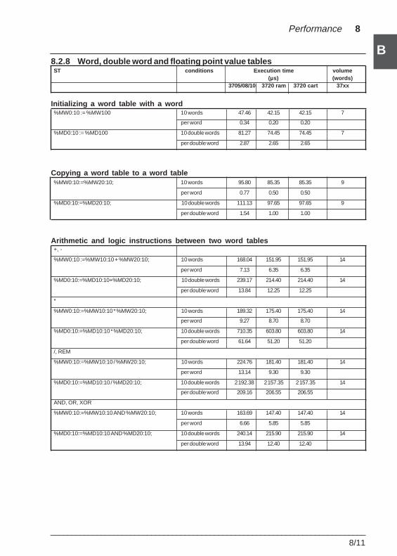
___________________________________________________________________________8/11
B
B
Performance 8
8.2.8 Word, double word and floating point value tablesST conditions Execution time volume
(µs) (words)3705/08/10 3720 ram 3720 cart 37xx
Initializing a word table with a word%MW0:10 := %MW100 10 words 47.46 42.15 42.15 7
per word 0.34 0.20 0.20
%MD0:10 := %MD100 10 double words 81.27 74.45 74.45 7
per double word 2.87 2.65 2.65
Copying a word table to a word table%MW0:10:=%MW20:10; 10 words 95.80 85.35 85.35 9
per word 0.77 0.50 0.50
%MD0:10:=%MD20:10; 10 double words 111.13 97.65 97.65 9
per double word 1.54 1.00 1.00
Arithmetic and logic instructions between two word tables+, -
%MW0:10 :=%MW10:10 + %MW20:10; 10 words 168.04 151.95 151.95 14
per word 7.13 6.35 6.35
%MD0:10:=%MD10:10+%MD20:10; 10 double words 239.17 214.40 214.40 14
per double word 13.84 12.25 12.25
*
%MW0:10:=%MW10:10 * %MW20:10; 10 words 189.32 175.40 175.40 14
per word 9.27 8.70 8.70
%MD0:10:=%MD10:10 * %MD20:10; 10 double words 710.35 603.80 603.80 14
per double word 61.64 51.20 51.20
/, REM
%MW0:10:=%MW10:10 / %MW20:10; 10 words 224.76 181.40 181.40 14
per word 13.14 9.30 9.30
%MD0:10:=%MD10:10 / %MD20:10; 10 double words 2 192.38 2 157.35 2 157.35 14
per double word 209.16 206.55 206.55
AND, OR, XOR
%MW0:10:=%MW10:10 AND %MW20:10; 10 words 163.69 147.40 147.40 14
per word 6.66 5.85 5.85
%MD0:10:=%MD10:10 AND %MD20:10; 10 double words 240.14 215.90 215.90 14
per double word 13.94 12.40 12.40
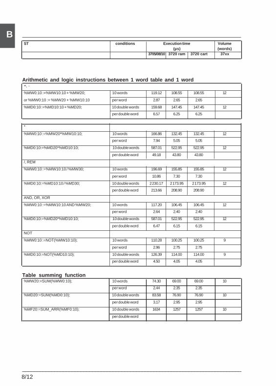
8/12___________________________________________________________________________
BST conditions Execution time Volume
(µs) (words)3705/08/10 3720 ram 3720 cart 37xx
Arithmetic and logic instructions between 1 word table and 1 word+, -
%MW0:10 :=%MW10:10 + %MW20; 10 words 119.12 108.55 108.55 12
or %MW0:10 := %MW20 + %MW10:10 per word 2.87 2.65 2.65
%MD0:10 :=%MD10:10 + %MD20; 10 double words 159.68 147.45 147.45 12
per double word 6.57 6.25 6.25
*
%MW0:10 :=%MW20*%MW10:10; 10 words 166.86 132.45 132.45 12
per word 7.94 5.05 5.05
%MD0:10:=%MD20*%MD10:10; 10 double words 587.01 522.95 522.95 12
per double word 49.18 43.80 43.80
/, REM
%MW0:10 :=%MW10:10 / %MW30; 10 words 196.69 155.85 155.85 12
per word 10.86 7.30 7.30
%MD0:10:=%MD10:10 / %MD30; 10 double words 2 230.17 2 173.95 2 173.95 12
per double word 213.66 208.90 208.90
AND, OR, XOR
%MW0:10 :=%MW10:10 AND %MW20; 10 words 117.20 106.45 106.45 12
per word 2.64 2.40 2.40
%MD0:10:=%MD20*%MD10:10; 10 double words 587.01 522.95 522.95 12
per double word 6.47 6.15 6.15
NOT
%MW0:10 :=NOT(%MW10:10); 10 words 110.28 100.25 100.25 9
per word 2.96 2.75 2.75
%MD0:10:=NOT(%MD10:10); 10 double words 126.39 114.00 114.00 9
per double word 4.50 4.05 4.05
Table summing function%MW20:=SUM(%MW0:10); 10 words 74.30 69.00 69.00 10
per word 2.44 2.35 2.35
%MD20:=SUM(%MD0:10); 10 double words 83.58 76.90 76.90 10
per double word 3.17 2.95 2.95
%MF20:=SUM_ARR(%MF0:10); 10 double words 1634 1257 1257 10
per double word
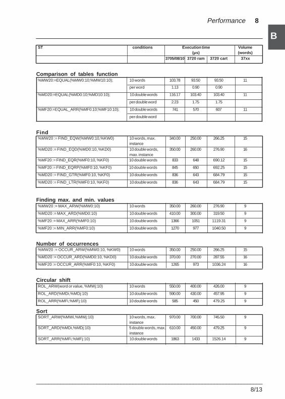
___________________________________________________________________________8/13
B
B
Performance 8
ST conditions Execution time Volume(µs) (words)
3705/08/10 3720 ram 3720 cart 37xx
Comparison of tables function%MW20:=EQUAL(%MW0:10;%MW10:10); 10 words 103.78 93.50 93.50 11
per word 1.13 0.90 0.90
%MD20:=EQUAL(%MD0:10;%MD10:10); 10 double words 116.17 103.40 103.40 11
per double word 2.23 1.75 1.75
%MF20:=EQUAL_ARR(%MF0:10;%MF10:10); 10 double words 741 570 607 11
per double word
Find%MW20 := FIND_EQW(%MW0:10,%KW0) 10 words, max. 340.00 250.00 266.25 15
instance%MD20 := FIND_EQD(%MD0:10, %KD0) 10 double words, 350.00 260.00 276.90 16
max. instance%MF20 := FIND_EQR(%MF0:10, %KF0) 10 double words 833 648 690.12 15
%MF20 := FIND_EQRP(%MF0:10, %KF0) 10 double words 845 650 692.25 15
%MD20 := FIND_GTR(%MF0:10, %KF0) 10 double words 836 643 684.79 15
%MD20 := FIND_LTR(%MF0:10, %KF0) 10 double words 836 643 684.79 15
Finding max. and min. values%MW20 := MAX_ARW(%MW0:10) 10 words 350.00 260.00 276.90 9
%MD20 := MAX_ARD(%MD0:10) 10 double words 410.00 300.00 319.50 9
%MF20 := MAX_ARR(%MF0:10) 10 double words 1366 1051 1119.31 9
%MF20 := MIN_ARR(%MF0:10) 10 double words 1270 977 1040.50 9
Number of occurrences%MW20 := OCCUR_ARW(%MW0:10, %KW0) 10 words 350.00 250.00 266.25 15
%MD20 := OCCUR_ARD(%MD0:10, %KD0) 10 double words 370.00 270.00 287.55 16
%MF20 := OCCUR_ARR(%MF0:10, %KF0) 10 double words 1265 973 1036.24 16
Circular shiftROL_ARW(word or value, %MWj:10) 10 words 550.00 400.00 426.00 9
ROL_ARD(%MDi,%MDj:10) 10 double words 590.00 430.00 457.95 9
ROL_ARR(%MFi,%MFj:10) 10 double words 585 450 479.25 9
SortSORT_ARW(%MWi,%MWj:10) 10 words, max. 970.00 700.00 745.50 9
instanceSORT_ARD(%MDi,%MDj:10) 5 double words, max. 610.00 450.00 479.25 9
instanceSORT_ARR(%MFi,%MFj:10) 10 double words 1863 1433 1526.14 9
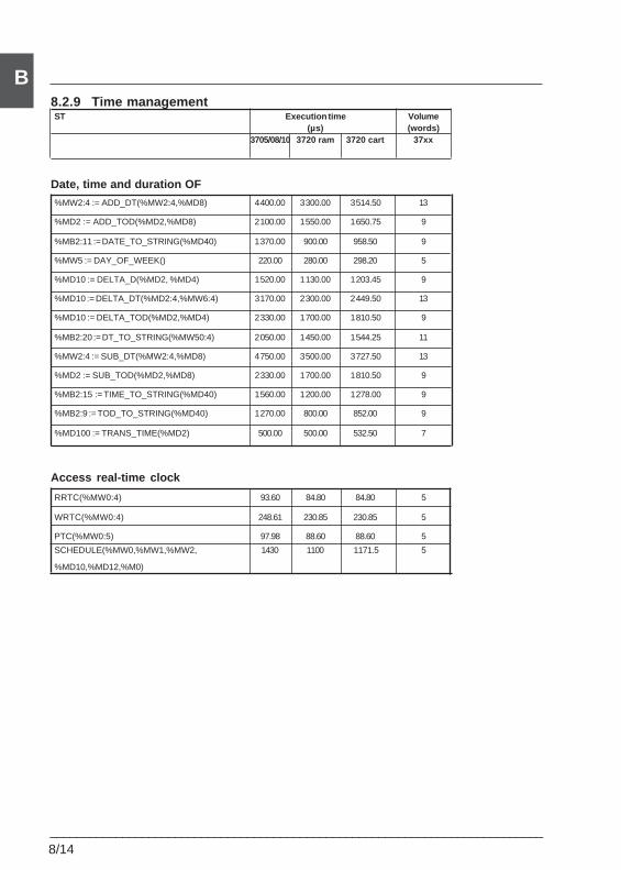
8/14___________________________________________________________________________
B8.2.9 Time managementST Execution time Volume
(µs) (words)3705/08/10 3720 ram 3720 cart 37xx
Date, time and duration OF
%MW2:4 := ADD_DT(%MW2:4,%MD8) 4 400.00 3 300.00 3 514.50 13
%MD2 := ADD_TOD(%MD2,%MD8) 2 100.00 1 550.00 1 650.75 9
%MB2:11 := DATE_TO_STRING(%MD40) 1 370.00 900.00 958.50 9
%MW5 := DAY_OF_WEEK() 220.00 280.00 298.20 5
%MD10 := DELTA_D(%MD2, %MD4) 1 520.00 1 130.00 1 203.45 9
%MD10 := DELTA_DT(%MD2:4,%MW6:4) 3 170.00 2 300.00 2 449.50 13
%MD10 := DELTA_TOD(%MD2,%MD4) 2 330.00 1 700.00 1 810.50 9
%MB2:20 := DT_TO_STRING(%MW50:4) 2 050.00 1 450.00 1 544.25 11
%MW2:4 := SUB_DT(%MW2:4,%MD8) 4 750.00 3 500.00 3 727.50 13
%MD2 := SUB_TOD(%MD2,%MD8) 2 330.00 1 700.00 1 810.50 9
%MB2:15 := TIME_TO_STRING(%MD40) 1 560.00 1 200.00 1 278.00 9
%MB2:9 := TOD_TO_STRING(%MD40) 1 270.00 800.00 852.00 9
%MD100 := TRANS_TIME(%MD2) 500.00 500.00 532.50 7
Access real-time clock
RRTC(%MW0:4) 93.60 84.80 84.80 5
WRTC(%MW0:4) 248.61 230.85 230.85 5
PTC(%MW0:5) 97.98 88.60 88.60 5
SCHEDULE(%MW0,%MW1,%MW2, 1430 1100 1171.5 5
%MD10,%MD12,%M0)
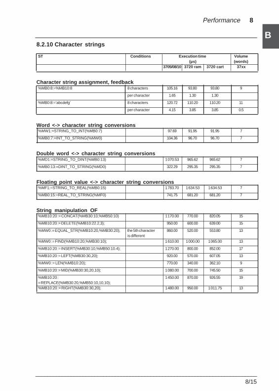
___________________________________________________________________________8/15
B
B
Performance 8
8.2.10 Character strings
ST Conditions Execution time Volume(µs) (words)
3705/08/10 3720 ram 3720 cart 37xx
Character string assignment, feedback%MB0:8:=%MB10:8 8 characters 105.16 93.80 93.80 9
per character 1.65 1.30 1.30
%MB0:8:=’abcdefg’ 8 characters 120.72 110.20 110.20 11
per character 4.15 3.85 3.85 0.5
Word <-> character string conversions%MW1:=STRING_TO_INT(%MB0:7) 97.69 91.95 91.95 7
%MB0:7:=INT_TO_STRING(%MW0) 104.36 96.70 96.70 7
Double word <-> character string conversions%MD1:=STRING_TO_DINT(%MB0:13) 1 070.53 965.62 965.62 7
%MB0:13:=DINT_TO_STRING(%MD0) 322.29 295.35 295.35 7
Floating point value <-> character string conversions%MF1:=STRING_TO_REAL(%MB0:15) 1 783.70 1 634.53 1 634.53 7
%MB0:15:=REAL_TO_STRING(%MF0) 741.75 681.20 681.20 7
String manipulation OF%MB10:20 := CONCAT(%MB30:10,%MB50:10) 1 170.00 770.00 820.05 15
%MB10:20 := DELETE(%MB10:22.2,3); 950.00 600.00 639.00 15
%MW0 := EQUAL_STR(%MB10:20,%MB30:20); the 5th character 860.00 520.00 553.80 13is different
%MW0 := FIND(%MB10:20,%MB30:10); 1 610.00 1 000.00 1 065.00 13
%MB10:20 := INSERT(%MB30:10,%MB50:10.4); 1 270.00 800.00 852.00 17
%MB10:20 := LEFT(%MB30:30,20); 920.00 570.00 607.05 13
%MW0 := LEN(%MB10:20); 770.00 340.00 362.10 9
%MB10:20 := MID(%MB30:30,20,10); 1 080.00 700.00 745.50 15
%MB10:20 : 1 450.00 870.00 926.55 19= REPLACE(%MB30:20,%MB50:10,10,10);%MB10:20 := RIGHT(%MB30:30,20); 1 480.00 950.00 1 011.75 13
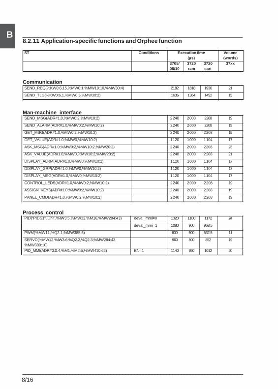
8/16___________________________________________________________________________
B8.2.11 Application-specific functions and Orphee function
ST Conditions Execution time Volume(µs) (words)
3705/ 3720 3720 37xx08/10 ram cart
CommunicationSEND_REQ(%KW0:6,15,%MW0:1,%MW10:10,%MW30:4) 2182 1818 1936 21
SEND_TLG(%KW0:6,1,%MW0:5,%MW30:2) 1636 1364 1452 15
Man-machine interfaceSEND_MSG(ADR#1.0,%MW0:2,%MW10:2) 2 240 2 000 2208 19
SEND_ALARM(ADR#1.0,%MW0:2,%MW10:2) 2 240 2 000 2208 19
GET_MSG(ADR#1.0,%MW0:2,%MW10:2) 2 240 2 000 2 208 19
GET_VALUE(ADR#1.0,%MW0,%MW10:2) 1 120 1 000 1 104 17
ASK_MSG(ADR#1.0,%MW0:2,%MW10:2,%MW20:2) 2 240 2 000 2 208 23
ASK_VALUE(ADR#1.0,%MW0,%MW10:2,%MW20:2) 2 240 2 000 2 208 21
DISPLAY_ALRM(ADR#1.0,%MW0,%MW10:2) 1 120 1 000 1 104 17
DISPLAY_GRP(ADR#1.0,%MW0,%MW10:2) 1 120 1 000 1 104 17
DISPLAY_MSG(ADR#1.0,%MW0,%MW10:2) 1 120 1 000 1 104 17
CONTROL_LEDS(ADR#1.0,%MW0:2,%MW10:2) 2 240 2 000 2 208 19
ASSIGN_KEYS(ADR#1.0,%MW0:2,%MW10:2) 2 240 2 000 2 208 19
PANEL_CMD(ADR#1.0,%MW0:2,%MW10:2) 2 240 2 000 2 208 19
Process controlPID(“PIDS1”,’Unit’,%IW3.5,%MW12,%M16,%MW284:43) deval_mmi=0 1320 1100 1172 24
deval_mmi=1 1080 900 958.5
PWM(%MW11,%Q2.1,%MW385:5) 600 500 532.5 11
SERVO(%MW12,%IW3.6,%Q2.2,%Q2.3,%MW284:43, 960 800 852 19%MW390:10)PID_MMI(ADR#0.0.4,%M1,%M2:5,%MW410:62) EN=1 1140 950 1012 20
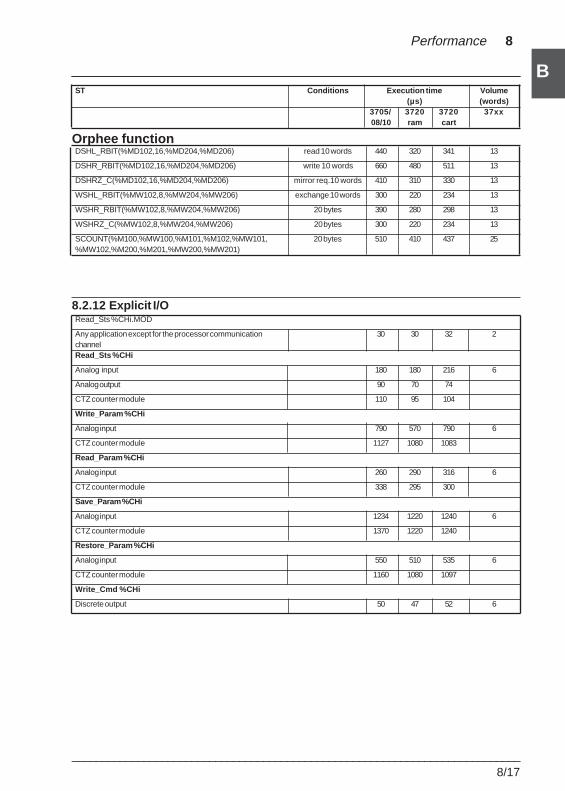
___________________________________________________________________________8/17
B
B
Performance 8
ST Conditions Execution time Volume(µs) (words)
3705/ 3720 3720 37xx08/10 ram cart
Orphee functionDSHL_RBIT(%MD102,16,%MD204,%MD206) read 10 words 440 320 341 13
DSHR_RBIT(%MD102,16,%MD204,%MD206) write 10 words 660 480 511 13
DSHRZ_C(%MD102,16,%MD204,%MD206) mirror req.10 words 410 310 330 13
WSHL_RBIT(%MW102,8,%MW204,%MW206) exchange 10 words 300 220 234 13
WSHR_RBIT(%MW102,8,%MW204,%MW206) 20 bytes 390 280 298 13
WSHRZ_C(%MW102,8,%MW204,%MW206) 20 bytes 300 220 234 13
SCOUNT(%M100,%MW100,%M101,%M102,%MW101, 20 bytes 510 410 437 25%MW102,%M200,%M201,%MW200,%MW201)
8.2.12 Explicit I/ORead_Sts %CHi.MOD
Any application except for the processor communication 30 30 32 2channelRead_Sts %CHi
Analog input 180 180 216 6
Analog output 90 70 74
CTZ counter module 110 95 104
Write_Param %CHi
Analog input 790 570 790 6
CTZ counter module 1127 1080 1083
Read_Param %CHi
Analog input 260 290 316 6
CTZ counter module 338 295 300
Save_Param %CHi
Analog input 1234 1220 1240 6
CTZ counter module 1370 1220 1240
Restore_Param %CHi
Analog input 550 510 535 6
CTZ counter module 1160 1080 1097
Write_Cmd %CHi
Discrete output 50 47 52 6
8/18___________________________________________________________________________
B8.3 TSX 57 performance
A more convenient method of displaying the processors has been used in the rest of thisdocument, by grouping them into 3 families :
Reference Processors
A TSX 57 10 and PCX 57 10
B TSX 57 20, TSX 57 25, TSX 57 30, TSX 57 35PMX 57 10, PCX 57 35
C TSX 57 40, TSX 57 45PMX 57 20, PMX 57 35, PMX 57 45
Note : in the rest of this document, the 3 families are shown at the foot of each page as areminder.
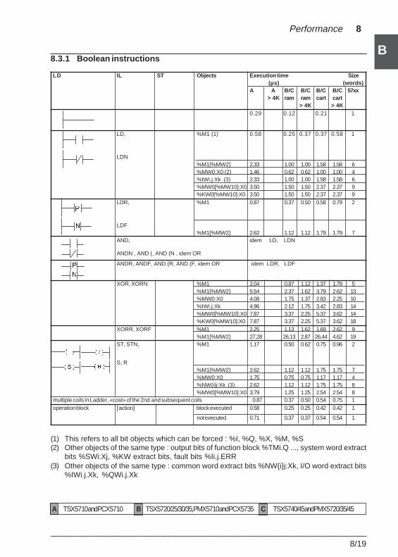
___________________________________________________________________________8/19
B
B
Performance 8
8.3.1 Boolean instructions
LD IL ST Objects Execution time Size(µs) (words)
A A B/C B/C B/C B/C 57xx> 4K ram ram cart cart
> 4K > 4K0.29 0.12 0.21 1
LD, %M1 (1) 0.58 0.25 0.37 0.37 0.58 1
LDN%M1[%MW2] 2.33 1.00 1.00 1.58 1.58 6%MW0:X0 (2) 1.46 0.62 0.62 1.00 1.00 4%IWi.j:Xk (3) 2.33 1.00 1.00 1.58 1.58 6%MW0[%MW10]:X0 3.50 1.50 1.50 2.37 2.37 9%KW0[%MW10]:X0 3.50 1.50 1.50 2.37 2.37 9
LDR, %M1 0.87 0.37 0.50 0.58 0.79 2
LDF%M1[%MW2] 2.62 1.12 1.12 1.79 1.79 7
AND, idem LD, LDN
ANDN , AND (, AND (N , idem OR
ANDR, ANDF, AND (R, AND (F, idem OR idem LDR, LDF
XOR, XORN %M1 2.04 0.87 1.12 1.37 1.79 5%M1[%MW2] 5.54 2.37 1.62 3.79 2.62 13%MW0:X0 4.08 1.75 1.37 2.83 2.25 10%IWi.j:Xk 4.96 2.12 1.75 3.42 2.83 14%MW0[%MW10]:X0 7.87 3.37 2.25 5.37 3.62 14%KW0[%MW10]:X0 7.87 3.37 2.25 5.37 3.62 18
XORR, XORF %M1 2.25 1.13 1.62 1.69 2.62 9%M1[%MW2] 27.28 26.13 2.87 26.44 4.62 19
ST, STN, %M1 1.17 0.50 0.62 0.75 0.96 2
S, R%M1[%MW2] 2.62 1.12 1.12 1.75 1.75 7%MW0:X0 1.75 0.75 0.75 1.17 1.17 4%NW{i}j:Xk (3) 2.62 1.12 1.12 1.75 1.75 8%MW0[%MW10]:X0 3.79 1.25 1.25 2.54 2.54 8
multiple coils in Ladder, «cost» of the 2nd and subsequent coils 0.87 0.37 0.50 0.54 0.75 1operation block [ action] block executed 0.58 0.25 0.25 0.42 0.42 1
not executed 0.71 0.37 0.37 0.54 0.54 1
(1) This refers to all bit objects which can be forced : %I, %Q, %X, %M, %S(2) Other objects of the same type : output bits of function block %TMi.Q ..., system word extract
bits %SWi:Xj, %KW extract bits, fault bits %Ii.j.ERR(3) Other objects of the same type : common word extract bits %NW{i}j:Xk, I/O word extract bits
%IWi.j.Xk, %QWi.j.Xk
A TSX 57 10 and PCX 57 10 B TSX 57 20/25/30/35, PMX 57 10 and PCX 57 35 C TSX 57 40/45 and PMX 57 20/35/45
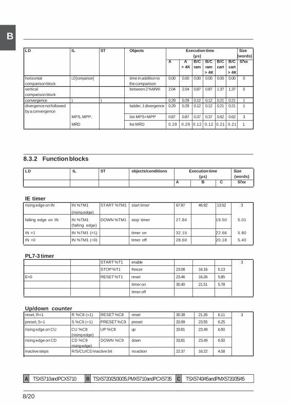
8/20___________________________________________________________________________
BLD IL ST Objects Execution time Size
(µs) (words)A A B/C B/C B/C B/C 57xx
> 4K ram ram cart cart> 4K > 4K
horizontal LD [comparison] time in addition to 0.00 0.00 0.00 0.00 0.00 0.00 0comparison block the comparisonvertical between 2 %MWi 2.04 2.04 0.87 0.87 1.37 1.37 5comparison blockconvergence ) ) 0.29 0.29 0.12 0.12 0.21 0.21 1divergence not followed ladder, 1 divergence 0.29 0.29 0.12 0.12 0.21 0.21 1by a convergence
MPS, MPP, list MPS+MPP 0.87 0.87 0.37 0.37 0.62 0.62 3
MRD list MRD 0.29 0.29 0.12 0.12 0.21 0.21 1
8.3.2 Function blocks
LD IL ST objects/conditions Execution time Size(µs) (words)
A B C 57xx
IE timerrising edge on IN IN %TM1 START %TM1 start timer 67.87 46.92 13.52 3
(rising edge)
falling edge on IN IN %TM1 DOWN %TM1 stop timer 27.84 19.50 5.01(falling edge)
IN =1 IN %TM1 (=1) timer on 32.15 22.66 5.80
IN =0 IN %TM1 (=0) timer off 28.60 20.18 5.40
PL7-3 timerSTART %T1 enable 3
STOP %T1 freeze 23.08 16.16 5.13
E=0 RESET %T1 reset 23.46 16.26 5.85
timer on 30.40 21.51 5.78
timer off
Up/down counterreset, R=1 R %C8 (=1) RESET %C8 reset 30.38 21.26 6.11 3
preset, S=1 S %C9 (=1) PRESET %C9 preset 33.99 23.55 6.25
rising edge on CU CU %C8 UP %C8 up 33.81 23.49 6.50(rising edge)
rising edge on CD CD %C9 DOWN %C9 down 33.81 23.49 6.50rising edge)
inactive steps R/S/CU/CD inactive bit no action 22.37 16.22 4.58
A TSX 57 10 and PCX 57 10 B TSX 57 20/25/30/35, PMX 57 10 and PCX 57 35 C TSX 57 40/45 and PMX 57 20/35/45
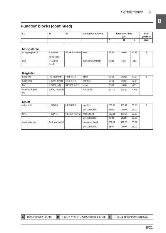
___________________________________________________________________________8/21
B
B
Performance 8
Function blocks (continued)
LD IL ST objects/conditions Execution time Size(µs) (words)
A B C 57xx
Monostablerising edge on S S %MN0, START %MN0 start 57.42 40.65 11.88 3
rising edge
S=1 S %MN0, active monostable 20.38 14.11 4.04S=1/0
Registeredge on I I %R2 (front) PUT %R2 store 35.69 24.92 6.72 3
edge on O O %R2 (front) GET %R2 retrieve 35.69 24.92 6.72
R=1 R %R1 (=1) RESET %R2 reset 26.83 18.80 6.11
inactive inputs I/O/R, inactive no action 20.71 15.50 4.62bit
Drumedge on U U %DR0 UP %DR1 up, fixed 268.69 185.41 58.68 3
per control bit 25.00 25.00 25.00
R=1 R %DR1 RESET %DR2 reset, fixed 257.01 176.06 57.00
per control bit 25.00 25.00 25.00
inactive inputs R/U, inactive bit no action, fixed 259.07 179.06 56.82
per control bit 25.00 25.00 25.00
A TSX 57 10 and PCX 57 10 B TSX 57 20/25/30/35, PMX 57 10 and PCX 57 35 C TSX 57 40/45 and PMX 57 20/35/45
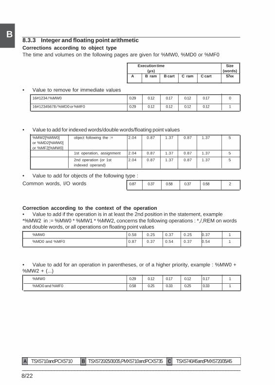
8/22___________________________________________________________________________
B8.3.3 Integer and floating point arithmeticCorrections according to object typeThe time and volumes on the following pages are given for %MW0, %MD0 or %MF0
Execution time Size(µs) (words)
A B ram B cart C ram C cart 57xx
• Value to remove for immediate values
16#1234 / %MW0 0.29 0.12 0.17 0.12 0.17 0
16#12345678 / %MD0 or %MF0 0.29 0.12 0.12 0.12 0.12 1
• Value to add for indexed words/double words/floating point values%MW2[%MW0] object following the := 2.04 0.87 1.37 0.87 1.37 5or %MD2[%MW0]or %MF2[%MW0]
1st operation, assignment 2.04 0.87 1.37 0.87 1.37 5
2nd operation (or 1st 2.04 0.87 1.37 0.87 1.37 5indexed operand)
• Value to add for objects of the following type :
Common words, I/O words 0.87 0.37 0.58 0.37 0.58 2
Correction according to the context of the operation• Value to add if the operation is in at least the 2nd position in the statement, example*%MW2 in := %MW0 * %MW1 * %MW2, concerns the following operations : *,/,REM on wordsand double words, or all operations on floating point values
%MW0 0.58 0.25 0.37 0.25 0.37 1
%MD0 and %MF0 0.87 0.37 0.54 0.37 0.54 1
• Value to add for an operation in parentheses, or of a higher priority, example : %MW0 +%MW2 + (...)
%MW0 0.29 0.12 0.17 0.12 0.17 1
%MD0 and %MF0 0.58 0.25 0.33 0.25 0.33 1
A TSX 57 10 and PCX 57 10 B TSX 57 20/25/30/35, PMX 57 10 and PCX 57 35 C TSX 57 40/45 and PMX 57 20/35/45
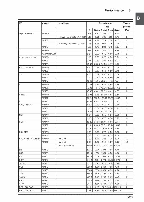
___________________________________________________________________________8/23
B
B
Performance 8
ST objects conditions Execution time Volume
(µs) (words)
A B ram B cart C ram C cart 57xx
object after the := %MW0 0.87 0.37 0.58 0.37 0.58 2
%MW0+(..., or before *, /, REM 1.17 0.50 0.75 0.50 0.75 2
%MD0 1.17 0.50 0.75 0.50 0.75 2
%MD0+(..., or before *, /, REM 1.75 0.75 1.08 0.75 1.08 2
%MF0 1.75 0.75 1.08 0.75 1.08 2
:= %MW0 0.87 0.37 0.58 0.37 0.58 2
%MD0 and %MF0 1.17 0.50 0.75 0.50 0.75 2
=, <>, <=, <, >, >= %MW0 1.17 0.50 0.79 0.50 0.79 4
%MD0 1.46 0.62 1.04 0.62 1.04 4
%MF0 48.36 33.88 34.13 4.17 4.42 4
AND, OR, XOR %MW0 0.87 0.37 0.58 0.37 0.58 3
%MD0 1.17 0.50 0.75 0.50 0.75 3
+, - %MW0 0.87 0.37 0.58 0.37 0.58 3
%MD0 1.17 0.50 0.75 0.50 0.75 3
%MF0 99.42 71.51 71.76 4.42 4.67 3
* %MW0 10.83 9.14 9.35 4.65 4.86 3
%MD0 55.31 42.71 42.96 15.26 15.51 3
%MF0 87.60 63.61 63.86 4.42 4.67 3
/, REM %MW0 11.93 9.99 10.20 4.94 5.15 3
%MD0 333.15 226.54226.79 49.38 49.63 3
/ %MF0 95.83 68.51 68.76 5.72 5.97 3
ABS, -object %MW0 0.87 0.37 0.58 0.37 0.58 2
%MD0 1.17 0.54 0.75 0.54 0.75 2
%MF0 18.82 13.01 13.26 3.67 3.92 2
NOT %MW0 0.87 0.37 0.58 0.37 0.58 2
%MD0 1.17 0.54 0.75 0.54 0.75 2
SQRT %MW0 22.20 16.24 16.45 5.53 5.74 3
%MD0 111.29 89.66 89.91 16.14 16.39 3
%MF0 233.62 173.01173.26 5.10 5.35 3
INC, DEC %MW0 1.17 0.50 0.75 0.50 0.75 2
%MD0 1.75 0.75 1.08 0.75 1.08 2
SHL, SHR, ROL, ROR %MW0 for 1 bit 2.92 1.25 1.96 1.25 1.96 10
%MD0 for 1 bit 3.21 1.37 2.12 1.37 2.12 10
per additional bit 0.042 0.042 0.042 0.042 0.042
LN %MF0 1711 1270 1270 4.53 4.78 3
LOG %MF0 1819 1350 1350 4.53 4.78 3
EXP %MF0 1442 1070 1070 12.03 12.28 3
EXPT %MF0 3412 2624 2775 98.70 98.70 3
TRUNC %MF0 215 165 175 52.40 52.40 3
COS %MF0 3530 2620 2620 4.53 4.78 3
SIN %MF0 3544 2630 2630 4.53 4.78 3
TAN %MF0 3665 2720 2720 4.53 4.78 3
ACOS %MF0 5093 3780 3780 5.33 5.58 3
ASIN %MF0 5093 3780 3780 6.73 6.98 3
ATAN %MF0 3476 2580 2580 4.33 4.58 3
DEG_TO_RAD %MF0 814 626 662 139.90139.90 3
RAD_TO_DEG %MF0 791 608 643 140.20140.20 3
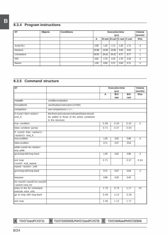
8/24___________________________________________________________________________
B8.3.4 Program instructions
ST Objects Conditions Execution time Volume(µs) (words)
A B ram B cart C ram C cart 57xx
Jump %Li 2.58 1.25 1.71 1.25 1.71 3
Maskevt 33.98 23.96 23.96 9.59 9.59 1
Unmaskevt 34.54 24.41 24.41 9.77 9.77 1
SRi 3.92 1.75 2.42 1.75 2.42 2
Return 1.00 0.50 0.71 0.50 0.71 2
8.3.5 Command structure
ST Execution time Volume(µs) (words)
A B/C B/C 57xxram cart
<cond> condition evaluation
forceable bit see Boolean instruction LD %M1
comparison see comparisons =,<,> ...
if <cond > then <action> the times and volumes indicated below shouldend_if; be added to those of the action contained
in the structuretrue condition 0.58 0.25 0.42 2
false condition (jump) 0.71 0.37 0.54
If <cond> then <action1><action2> end_if;true condition 1.29 0.62 0.96 4
false condition 0.71 0.37 0.54
while <cond> do.<action>end_whilego to loop with loop-back 1.29 0.62 0.96 2
exit loop 0.71 0.37 0.54<cond> end_repeatrepeat <action> until
go to loop with loop-back 0.71 0.37 0.54 2
last pass 0.58 0.25 0.42
for <word1:=word2>to <word3> <action> end_forentry to the for command, 1.75 0.75 1.17 15execute once onlygo to loop with loop-back 5.08 2.12 3.29
exit loop 2.46 1.12 1.71
A TSX 57 10 and PCX 57 10 B TSX 57 20/25/30/35, PMX 57 10 and PCX 57 35 C TSX 57 40/45 and PMX 57 20/35/45
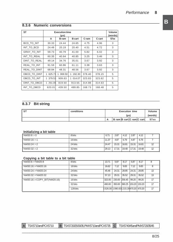
___________________________________________________________________________8/25
B
B
Performance 8
8.3.6 Numeric conversions
ST Execution time Volume(µs) (words)
A B ram B cart C ram C cart 57xx
BCD_TO_INT 30.33 24.44 24.65 4.75 4.96 3
INT_TO_BCD 24.48 20.19 20.40 4.51 4.72 3
GRAY_TO_INT 59.73 40.79 41.00 5.82 6.02 3
INT_TO_REAL 60.35 40.64 40.85 3.25 3.46 3
DINT_TO_REAL 49.14 34.76 35.01 3.67 3.92 3
REAL_TO_INT 91.59 60.86 61.11 3.38 3.63 3
REAL_TO_DINT 68.84 48.31 48.56 3.67 3.92 3
DBCD_TO_DINT 1 625.73 1 069.50 1 192.30 378.40 378.15 5
DBCD_TO_INT 1 379.53 909.63 1 014.07 323.83 323.62 5
DINT_TO_DBCD 1 251.05 819.50 913.55 314.88 314.63 5
INT_TO_DBCD 620.01 439.50 489.85 168.73 168.48 5
8.3.7 Bit string
ST conditions Execution time Volume
(µs) (words)
A B ram B cart C ram C cart 57xx
Initializing a bit table%M30:8 := 0 8 bits 6.71 2.87 4.12 2.87 4.12 7
%M30:16 := 1 16 bits 11.37 4.87 6.79 4.87 6.79 7
%M30:24 := 2 24 bits 24.47 15.31 16.81 15.31 16.81 12
%M30:32 := 2 32 bits 29.13 17.31 19.48 17.31 19.48 12
Copying a bit table to a bit table%M30:8 := %M20:8 8 bits 13.71 5.87 8.17 5.87 8.17 8
%M30:16 := %M20:16 16 bits 16.62 7.12 9.83 7.12 9.83 8
%M30:24 := %M20:24 24 bits 45.46 24.31 28.85 24.31 28.85 13
%M30:32 := %M20:32 32 bits 57.13 29.31 35.52 29.31 35.52 13
%M30:16 := COPY_BIT(%M20:16) 16 bits 322.00 230.00 256.45 99.20 99.20 17
32 bits 490.00 350.00 390.25 153.20 153.20 17
128 bits 1 526.00 1 090.001 215.35470.20 470.20 17
A TSX 57 10 and PCX 57 10 B TSX 57 20/25/30/35, PMX 57 10 and PCX 57 35 C TSX 57 40/45 and PMX 57 20/35/45
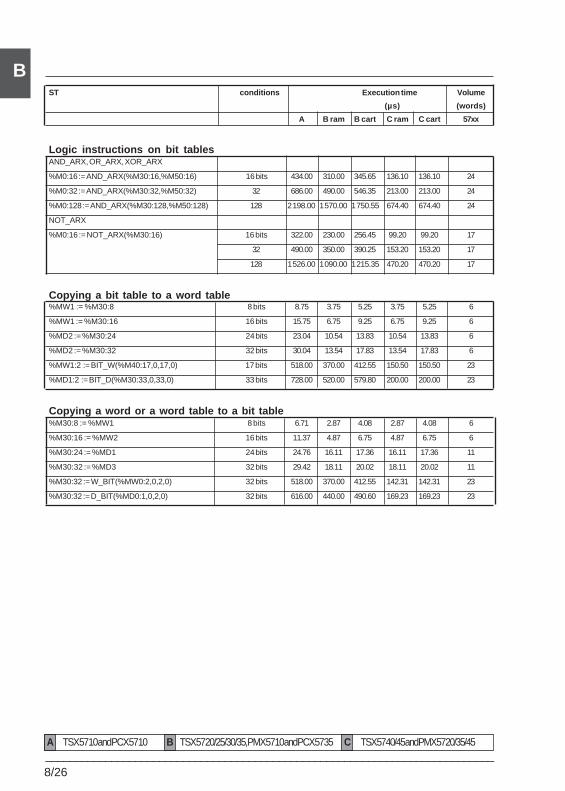
8/26___________________________________________________________________________
BST conditions Execution time Volume
(µs) (words)
A B ram B cart C ram C cart 57xx
Logic instructions on bit tablesAND_ARX, OR_ARX, XOR_ARX
%M0:16 := AND_ARX(%M30:16,%M50:16) 16 bits 434.00 310.00 345.65 136.10 136.10 24
%M0:32 := AND_ARX(%M30:32,%M50:32) 32 686.00 490.00 546.35 213.00 213.00 24
%M0:128 := AND_ARX(%M30:128,%M50:128) 128 2 198.00 1 570.00 1 750.55 674.40 674.40 24
NOT_ARX
%M0:16 := NOT_ARX(%M30:16) 16 bits 322.00 230.00 256.45 99.20 99.20 17
32 490.00 350.00 390.25 153.20 153.20 17
128 1 526.00 1 090.00 1 215.35 470.20 470.20 17
Copying a bit table to a word table%MW1 := %M30:8 8 bits 8.75 3.75 5.25 3.75 5.25 6
%MW1 := %M30:16 16 bits 15.75 6.75 9.25 6.75 9.25 6
%MD2 := %M30:24 24 bits 23.04 10.54 13.83 10.54 13.83 6
%MD2 := %M30:32 32 bits 30.04 13.54 17.83 13.54 17.83 6
%MW1:2 := BIT_W(%M40:17,0,17,0) 17 bits 518.00 370.00 412.55 150.50 150.50 23
%MD1:2 := BIT_D(%M30:33,0,33,0) 33 bits 728.00 520.00 579.80 200.00 200.00 23
Copying a word or a word table to a bit table%M30:8 := %MW1 8 bits 6.71 2.87 4.08 2.87 4.08 6
%M30:16 := %MW2 16 bits 11.37 4.87 6.75 4.87 6.75 6
%M30:24 := %MD1 24 bits 24.76 16.11 17.36 16.11 17.36 11
%M30:32 := %MD3 32 bits 29.42 18.11 20.02 18.11 20.02 11
%M30:32 := W_BIT(%MW0:2,0,2,0) 32 bits 518.00 370.00 412.55 142.31 142.31 23
%M30:32 := D_BIT(%MD0:1,0,2,0) 32 bits 616.00 440.00 490.60 169.23 169.23 23
A TSX 57 10 and PCX 57 10 B TSX 57 20/25/30/35, PMX 57 10 and PCX 57 35 C TSX 57 40/45 and PMX 57 20/35/45
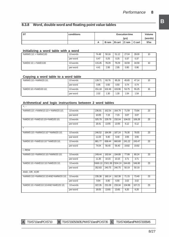
___________________________________________________________________________8/27
B
B
Performance 8
8.3.8 Word, double word and floating point value tables
ST conditions Execution time Volume
(µs) (words)
A B ram B cart C ram C cart 57xx
Initializing a word table with a word%MW0:10 := %MW100 10 words 74.48 50.16 51.12 27.04 28.00 10
per word 0.47 0.25 0.25 0.37 0.37
%MD0:10 := %MD100 10 words 115.45 78.29 79.29 33.59 34.59 10
per word 4.41 2.95 2.95 0.90 0.90
Copying a word table to a word table%MW0:10:=%MW20:10; 10 words 139.71 93.76 95.26 45.65 47.14 15
per word 0.95 0.50 0.50 0.74 0.74
%MD0:10:=%MD20:10; 10 words 151.18 102.46 103.96 53.75 55.25 15
per word 2.02 1.30 1.30 1.54 1.54
Arithmetical and logic instructions between 2 word tables+, -
%MW0:10 :=%MW10:10 + %MW20:10; 10 words 236.81 162.54 164.79 71.59 73.84 23
per word 10.05 7.15 7.15 3.07 3.07
%MD0:10:=%MD10:10+%MD20:10; 10 words 325.79 229.79 232.04 104.03 106.28 23
per word 18.41 13.55 13.55 6.12 6.12
*
%MW0:10:=%MW10:10 * %MW20:10; 10 words 246.52 184.99 187.24 76.30 78.55 23
par word 11.03 9.40 9.40 3.55 3.55
%MD0:10:=%MD10:10 * %MD20:10; 10 words 881.77 658.44 660.69 241.22 243.47 23
per word 74.04 56.40 56.40 19.82 19.82
/, REM
%MW0:10:=%MW10:10 / %MW20:10; 10 words 249.44 192.64 194.89 77.99 80.24 23
per word 11.35 10.15 10.15 3.71 3.71
%MD0:10:=%MD10:10 / %MD20:10; 10 words 3 669.10 2 501.99 2 504.24 544.65 546.90 23
per word 352.83 240.75 240.75 50.19 50.19
AND, OR, XOR
%MW0:10:=%MW10:10 AND %MW20:10; 10 words 235.38 160.14 162.39 71.15 73.40 23
per word 9.94 6.90 6.90 3.02 3.02
%MD0:10:=%MD10:10 AND %MD20:10; 10 words 322.35 231.09 233.34 104.96 107.21 23
per word 18.05 13.65 13.65 6.20 6.20
A TSX 57 10 and PCX 57 10 B TSX 57 20/25/30/35, PMX 57 10 and PCX 57 35 C TSX 57 40/45 and PMX 57 20/35/45
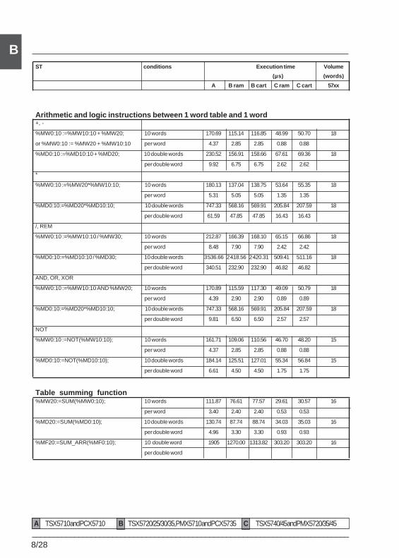
8/28___________________________________________________________________________
BST conditions Execution time Volume
(µs) (words)
A B ram B cart C ram C cart 57xx
Arithmetic and logic instructions between 1 word table and 1 word+, -
%MW0:10 :=%MW10:10 + %MW20; 10 words 170.69 115.14 116.85 48.99 50.70 18
or %MW0:10 := %MW20 + %MW10:10 per word 4.37 2.85 2.85 0.88 0.88
%MD0:10 :=%MD10:10 + %MD20; 10 double words 230.52 156.91 158.66 67.61 69.36 18
per double word 9.92 6.75 6.75 2.62 2.62
*
%MW0:10 :=%MW20*%MW10:10; 10 words 180.13 137.04 138.75 53.64 55.35 18
per word 5.31 5.05 5.05 1.35 1.35
%MD0:10:=%MD20*%MD10:10; 10 double words 747.33 568.16 569.91 205.84 207.59 18
per double word 61.59 47.85 47.85 16.43 16.43
/, REM
%MW0:10 :=%MW10:10 / %MW30; 10 words 212.87 166.39 168.10 65.15 66.86 18
per word 8.48 7.90 7.90 2.42 2.42
%MD0:10:=%MD10:10 / %MD30; 10 double words 3 536.66 2 418.56 2 420.31 509.41 511.16 18
per double word 340.51 232.90 232.90 46.82 46.82
AND, OR, XOR
%MW0:10 :=%MW10:10 AND %MW20; 10 words 170.89 115.59 117.30 49.09 50.79 18
per word 4.39 2.90 2.90 0.89 0.89
%MD0:10:=%MD20*%MD10:10; 10 double words 747.33 568.16 569.91 205.84 207.59 18
per double word 9.81 6.50 6.50 2.57 2.57
NOT
%MW0:10 :=NOT(%MW10:10); 10 words 161.71 109.06 110.56 46.70 48.20 15
per word 4.37 2.85 2.85 0.88 0.88
%MD0:10:=NOT(%MD10:10); 10 double words 184.14 125.51 127.01 55.34 56.84 15
per double word 6.61 4.50 4.50 1.75 1.75
Table summing function%MW20:=SUM(%MW0:10); 10 words 111.87 76.61 77.57 29.61 30.57 16
per word 3.40 2.40 2.40 0.53 0.53
%MD20:=SUM(%MD0:10); 10 double words 130.74 87.74 88.74 34.03 35.03 16
per double word 4.96 3.30 3.30 0.93 0.93
%MF20:=SUM_ARR(%MF0:10); 10 double word 1905 1270.00 1313.82 303.20 303.20 16
per double word
A TSX 57 10 and PCX 57 10 B TSX 57 20/25/30/35, PMX 57 10 and PCX 57 35 C TSX 57 40/45 and PMX 57 20/35/45
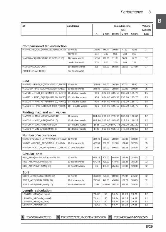
___________________________________________________________________________8/29
B
B
Performance 8
ST conditions Execution time Volume
(µs) (words)
A B ram B cart C ram C cart 57xx
Comparison of tables function%MW20:=EQUAL(%MW0:10;%MW10:10); 10 words 142.90 99.14 100.85 47.31 49.02 17
per word 1.14 0.95 0.95 0.83 0.83
%MD20:=EQUAL(%MD0:10;%MD10:10); 10 double words 155.56 110.06 111.81 56.02 57.77 17
per double word 2.33 2.00 2.00 1.69 1.69
%MF20:=EQUAL_ARR 10 double words 825 550.00 568.98 137.50 137.50 17
(%MF0:10;%MF10:10); per double word
Find%MW20 := FIND_EQW(%MW0:10,%KW0) 10 words 374.68 240.00 267.60 97.00 97.00 14
%MD20 := FIND_EQD(%MD0:10, %KD0) 10 double words 394.40 260.00 289.90 100.00 100.00 15
%MF20 := FIND_EQR(%MF0:10, %KF0) 10 double words 936 624.00 645.53 135.70 135.70 15
%MF20 := FIND_EQRP(%MF0:10, %KF0) 10 double words 936 624.00 645.53 135.70 135.70 15
%MD20 := FIND_GTR(%MF0:10, %KF0) 10 double words 936 624.00 645.53 135.70 135.70 15
%MD20 := FIND_LTR(%MF0:10, %KF0) 10 double words 936 624.00 645.53 135.70 135.70 15
Finding max. and min. values%MW20 := MAX_ARW(%MW0:10) 10 words 404.26 260.00 289.90 100.00 100.00 12
%MD20 := MAX_ARD(%MD0:10) 10 double words 483.14 310.00 345.65 119.23 119.23 12
%MF20 := MAX_ARR(%MF0:10) 10 double words 1555 1037.001072.78 261.20 261.20 12
%MD20 := MIN_ARR(%MF0:10) 10 double words 1443 962.00 995.19 240.50 240.50 12
Number of occurrences%MW20:=OCCUR_ARW(%MW0:10,%KW0) 10 words 394.40 260.00 289.90 100.00 100.00 14
%MD20:=OCCUR_ARD(%MD0:10,%KD0) 10 double words 423.98 280.00 312.20 107.69 107.69 15
%MF20 := OCCUR_ARR(%MF0:10, %KF0) 10 double words 1435 957.00 990.02 239.25 293.25 15
Circular shiftROL_ARW(word or value, %MWj:10) 10 words 621.18 400.00 446.00 153.85 153.85 12
ROL_ARD(%MDi,%MDj:10) 10 double words 670.48 430.00 479.45 165.38 165.38 12
ROL_ARR(%MFi,%MFj:10) 10 double words 654 436.00 451.04 109.00 109.00 12
SortSORT_ARW(%MWi,%MWj:10) 10 words 1 133.90 720.00 802.80 276.92 276.92 12
SORT_ARD(%MDi,%MDj:10) 10 double words 700.06 440.00 490.60 169.23 169.23 12
SORT_ARR(%MFi,%MFj:10) 10 double words 2150 1433.00 1482.44 358.25 358.25 12
Length calculationLENGTH_ARW(tab_word) 71.42 50 55.74 19.28 19.28 12
LENGTH_ARD(tab_dword) 71.42 50 55.74 19.28 19.28 12LENGTH_ARW(tab_real) 71.42 50 55.74 19.28 19.28 12LENGTH_ARX(tab_bit) 71.42 50 55.74 19.28 19.28 12
A TSX 57 10 and PCX 57 10 B TSX 57 20/25/30/35, PMX 57 10 and PCX 57 35 C TSX 57 40/45 and PMX 57 20/35/45
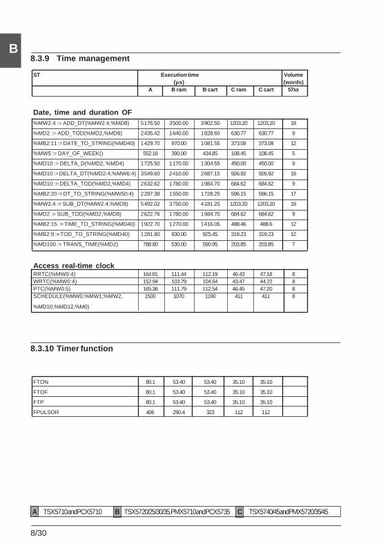
8/30___________________________________________________________________________
B8.3.9 Time management
ST Execution time Volume(µs) (words)
A B ram B cart C ram C cart 57xx
Date, time and duration OF%MW2:4 := ADD_DT(%MW2:4,%MD8) 5 176.50 3 500.00 3 902.50 1203.20 1203.20 19
%MD2 := ADD_TOD(%MD2,%MD8) 2 435.42 1 640.00 1 828.60 630.77 630.77 9
%MB2:11 := DATE_TO_STRING(%MD40) 1 429.70 970.00 1 081.55 373.08 373.08 12
%MW5 := DAY_OF_WEEK() 552.16 390.00 434.85 108.45 108.45 5
%MD10 := DELTA_D(%MD2, %MD4) 1 725.50 1 170.00 1 304.55 450.00 450.00 9
%MD10 := DELTA_DT(%MD2:4,%MW6:4) 3 549.60 2 410.00 2 687.15 926.92 926.92 19
%MD10 := DELTA_TOD(%MD2,%MD4) 2 632.62 1 780.00 1 984.70 684.62 684.62 9
%MB2:20 := DT_TO_STRING(%MW50:4) 2 297.38 1 550.00 1 728.25 596.15 596.15 17
%MW2:4 := SUB_DT(%MW2:4,%MD8) 5 492.02 3 750.00 4 181.25 1203.20 1203.20 19
%MD2 := SUB_TOD(%MD2,%MD8) 2 622.76 1 780.00 1 984.70 684.62 684.62 9
%MB2:15 := TIME_TO_STRING(%MD40) 1 922.70 1 270.00 1 416.05 488.46 488.6 12
%MB2:9 := TOD_TO_STRING(%MD40) 1 281.80 830.00 925.45 319.23 319.23 12
%MD100 := TRANS_TIME(%MD2) 788.80 530.00 590.95 203.85 203.85 7
Access real-time clockRRTC(%MW0:4) 164.81 111.44 112.19 46.43 47.18 8WRTC(%MW0:4) 152.94 103.79 104.54 43.47 44.22 8PTC(%MW0:5) 165.36 111.79 112.54 46.45 47.20 8SCHEDULE(%MW0,%MW1,%MW2, 1500 1070 1190 411 411 8
%MD10,%MD12,%M0)
8.3.10 Timer function
FTON 80.1 53.40 53.40 35.10 35.10
FTOF 80.1 53.40 53.40 35.10 35.10
FTP 80.1 53.40 53.40 35.10 35.10
FPULSOR 406 290.4 323 112 112
A TSX 57 10 and PCX 57 10 B TSX 57 20/25/30/35, PMX 57 10 and PCX 57 35 C TSX 57 40/45 and PMX 57 20/35/45
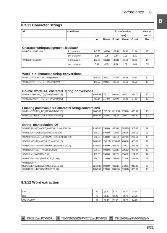
___________________________________________________________________________8/31
B
B
Performance 8
8.3.11 Character strings
ST conditions Execution time Volume
(µs) (words)
A B ram B cart C ram C cart 57xx
Character string assignment, feedback%MB0:8:=%MB10:8 8 characters 147.75 103.56 103.56 51.96 51.96 15
per character 1.64 1.25 1.25 1.21 1.21
%MB0:8:=’abcdefg’ 8 characters 193.86 136.88 136.88 56.53 56.53 14
per character 5.94 4.35 4.35 1.69 1.69 0.5
Word <-> character string conversions%MW1:=STRING_TO_INT(%MB0:7) 145.69 104.31 104.52 37.93 38.14 10
%MB0:7:=INT_TO_STRING(%MW0) 149.67 109.21 109.42 35.52 35.73 10
Double word <-> character string conversions%MD1:=STRING_TO_DINT(%MB0:13) 1 408.43 1 061.01 1 061.01 364.71 364.71 10
%MB0:13:=DINT_TO_STRING(%MD0) 411.64 317.69 317.94 97.35 97.60 10
Floating point value <-> character string conversions%MF1:=STRING_TO_REAL(%MB0:15) 2 606.63 1 815.08 1 815.33 635.96 635.96 10
%MB0:15:=REAL_TO_STRING(%MF0) 1 084.46 752.94 753.27 389.47 389.81 10
String manipulation OF%MB10:20 := CONCAT(%MB30:10,%MB50:10) 1 106.00 790.00 880.85 303.85 303.85 24
%MB10:20 := DELETE(%MB10:22,2,3); 896.00 640.00 713.60 246.15 246.15 21
%MW0 := EQUAL_STR(%MB10:20,%MB30:20); 756.00 540.00 602.10 207.69 207.69 19
%MW0 := FIND(%MB10:20,%MB30:10); 1 456.00 1 040.00 1 159.60 400.00 400.00 19
%MB10:20 := INSERT(%MB30:10,%MB50:10,4); 1 162.00 830.00 925.45 319.23 319.23 26
%MB10:20 := LEFT(%MB30:30,20); 826.00 590.00 657.85 226.92 226.92 19
%MW0 := LEN(%MB10:20); 490.00 350.00 390.25 134.62 134.62 12
%MB10:20 := MID(%MB30:30,20,10); 994.00 710.00 791.65 273.08 273.08 21
%MB10:20 :=REPLACE(%MB30:20,%MB50:10,10,10); 1 246.00 890.00 992.35 342.31 342.31 28%MB10:20 := RIGHT(%MB30:30,20); 1 358.00 970.00 1 081.55 373.08 373.08 19
8.3.12 Word extraction
LW 72 51.40 51.40 24.70 24.70
HW 72 51.40 51.40 24.70 24.70
CONCATW 72 51.40 51.40 24.70 24.70
A TSX 57 10 and PCX 57 10 B TSX 57 20/25/30/35, PMX 57 10 and PCX 57 35 C TSX 57 40/45 and PMX 57 20/35/45
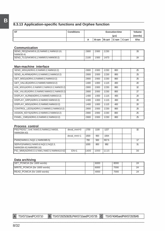
8/32___________________________________________________________________________
B8.3.13 Application-specific functions and Orphee function
ST Conditions Execution time Volume
(µs) (words)
A B ram B cart C ram C cart 57xx
CommunicationSEND_REQ(%KW0:6,15,%MW0:1,%MW10:10, 2 800 2 000 2 230 33%MW30:4)SEND_TLG(%KW0:6,1,%MW0:5,%MW30:2) 2 100 1 500 1 673 24
Man-machine interfaceSEND_MSG(ADR#1.0,%MW0:2,%MW10:2) 2 800 2 000 2 230 800 25
SEND_ALARM(ADR#1.0,%MW0:2,%MW10:2) 2 800 2 000 2 230 800 25
GET_MSG(ADR#1.0,%MW0:2,%MW10:2) 2 800 2 000 2 230 800 25
GET_VALUE(ADR#1.0,%MW0,%MW10:2) 1 400 1 000 1 115 400 20
ASK_MSG(ADR#1.0,%MW0:2,%MW10:2,%MW20:2) 2 800 2 000 2 230 800 32
ASK_VALUE(ADR#1.0,%MW0,%MW10:2,%MW20:2) 2 800 2 000 2 230 800 27
DISPLAY_ALRM(ADR#1.0,%MW0,%MW10:2) 1 400 1 000 1 115 400 20
DISPLAY_GRP(ADR#1.0,%MW0,%MW10:2) 1 400 1 000 1 115 400 20
DISPLAY_MSG(ADR#1.0,%MW0,%MW10:2) 1 400 1 000 1 115 400 20
CONTROL_LEDS(ADR#1.0,%MW0:2,%MW10:2) 2 800 2 000 2 230 800 25
ASSIGN_KEYS(ADR#1.0,%MW0:2,%MW10:2) 2 800 2 000 2 230 800 25
PANEL_CMD(ADR#1.0,%MW0:2,%MW10:2) 2 800 2 000 2 230 800 25
Process controlPID(“PIDS1”,’Unit’,%IW3.5,%MW12,%M16, deval_mmi=0 1700 1100 1227 32%MW284:43)
deval_mmi=1 1500 900 1004
PWM(%MW11,%Q2.1,%MW385:5) 700 500 557.5 17
SERVO(%MW12,%IW3.6,%Q2.2,%Q2.3, 1000 800 892 31%MW284:43,%MW390:10)PID_MMI(ADR#0.0.4,%M1,%M2:5,%MW410:62) EN=1 1400 1000 1115 30
Data archivingSET_PCMCIA (for 1600 words) 6000 8000 24
WRITE_PCMCIA (for 1600 words) 6000 7000 24
READ_PCMCIA (for 1600 words) 4000 7000 24
A TSX 57 10 and PCX 57 10 B TSX 57 20/25/30/35, PMX 57 10 and PCX 57 35 C TSX 57 40/45 and PMX 57 20/35/45
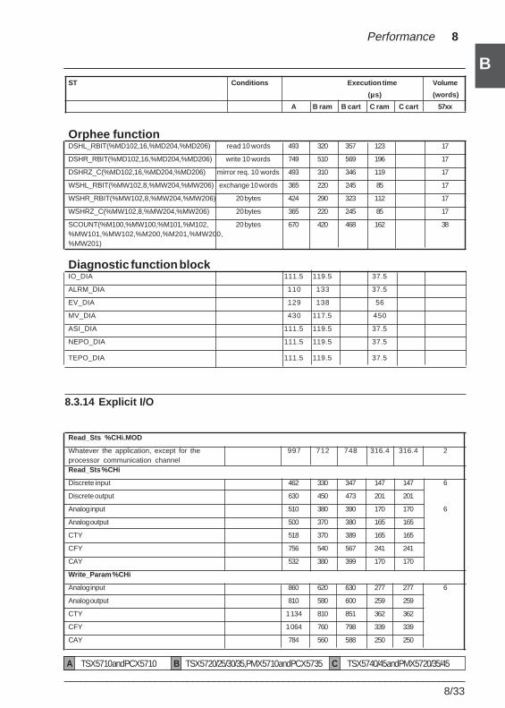
___________________________________________________________________________8/33
B
B
Performance 8
ST Conditions Execution time Volume
(µs) (words)
A B ram B cart C ram C cart 57xx
Orphee functionDSHL_RBIT(%MD102,16,%MD204,%MD206) read 10 words 493 320 357 123 17
DSHR_RBIT(%MD102,16,%MD204,%MD206) write 10 words 749 510 569 196 17
DSHRZ_C(%MD102,16,%MD204,%MD206) mirror req. 10 words 493 310 346 119 17
WSHL_RBIT(%MW102,8,%MW204,%MW206) exchange 10 words 365 220 245 85 17
WSHR_RBIT(%MW102,8,%MW204,%MW206) 20 bytes 424 290 323 112 17
WSHRZ_C(%MW102,8,%MW204,%MW206) 20 bytes 365 220 245 85 17
SCOUNT(%M100,%MW100,%M101,%M102, 20 bytes 670 420 468 162 38%MW101,%MW102,%M200,%M201,%MW200,%MW201)
Diagnostic function blockIO_DIA 111.5 119.5 37.5
ALRM_DIA 110 133 37.5
EV_DIA 129 138 56
MV_DIA 430 117.5 450
ASI_DIA 111.5 119.5 37.5
NEPO_DIA 111.5 119.5 37.5
TEPO_DIA 111.5 119.5 37.5
8.3.14 Explicit I/O
Read_Sts %CHi.MOD
Whatever the application, except for the 997 712 748 316.4 316.4 2processor communication channelRead_Sts %CHi
Discrete input 462 330 347 147 147 6
Discrete output 630 450 473 201 201
Analog input 510 380 390 170 170 6
Analog output 500 370 380 165 165
CTY 518 370 389 165 165
CFY 756 540 567 241 241
CAY 532 380 399 170 170
Write_Param %CHi
Analog input 860 620 630 277 277 6
Analog output 810 580 600 259 259
CTY 1 134 810 851 362 362
CFY 1 064 760 798 339 339
CAY 784 560 588 250 250
A TSX 57 10 and PCX 57 10 B TSX 57 20/25/30/35, PMX 57 10 and PCX 57 35 C TSX 57 40/45 and PMX 57 20/35/45
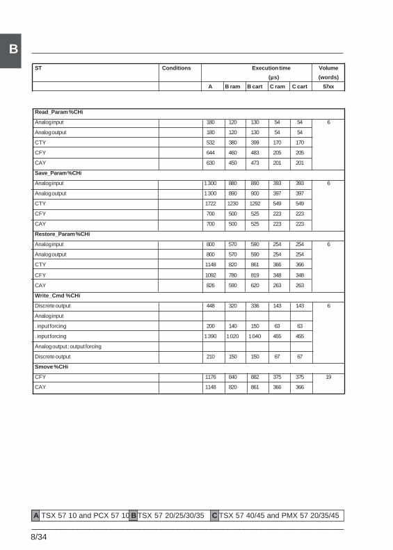
8/34___________________________________________________________________________
BST Conditions Execution time Volume
(µs) (words)
A B ram B cart C ram C cart 57xx
Read_Param %CHi
Analog input 180 120 130 54 54 6
Analog output 180 120 130 54 54
CTY 532 380 399 170 170
CFY 644 460 483 205 205
CAY 630 450 473 201 201
Save_Param %CHi
Analog input 1 300 880 890 393 393 6
Analog output 1 300 890 900 397 397
CTY 1722 1230 1292 549 549
CFY 700 500 525 223 223
CAY 700 500 525 223 223
Restore_Param %CHi
Analog input 800 570 590 254 254 6
Analog output 800 570 590 254 254
CTY 1148 820 861 366 366
CFY 1092 780 819 348 348
CAY 826 590 620 263 263
Write_Cmd %CHi
Discrete output 448 320 336 143 143 6
Analog input
. input forcing 200 140 150 63 63
. input forcing 1 390 1 020 1 040 455 455
Analog output : output forcing
Discrete output 210 150 150 67 67
Smove %CHi
CFY 1176 840 882 375 375 19
CAY 1148 820 861 366 366
A TSX 57 10 and PCX 57 10 B TSX 57 20/25/30/35 C TSX 57 40/45 and PMX 57 20/35/45
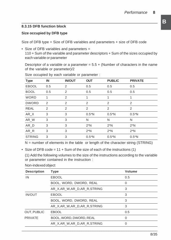
___________________________________________________________________________8/35
B
B
Performance 8
8.3.15 DFB function block
Size occupied by DFB type
Size of DFB type = Size of DFB variables and parameters + size of DFB code
• Size of DFB variables and parameters =110 + Sum of the variable and parameter descriptors + Sum of the sizes occupied byeach variable or parameter
Descriptor of a variable or a parameter = 5.5 + (Number of characters in the nameof the variable or parameter)/2
Size occupied by each variable or parameter :
Type IN IN/OUT OUT PUBLIC PRIVATE
EBOOL 0.5 2 0.5 0.5 0.5
BOOL 0.5 2 0.5 0.5 0.5
WORD 1 2 1 1 1
DWORD 2 2 2 2 2
REAL 2 2 2 2 2
AR_X 3 3 0.5*N 0.5*N 0.5*N
AR_W 3 3 N N N
AR_D 3 3 2*N 2*N 2*N
AR_R 3 3 2*N 2*N 2*N
STRING 3 3 0.5*N 0.5*N 0.5*N
N = number of elements in the table or length of the character string (STRING)
• Size of DFB code = 11 + Sum of the size of each of the instructions (1)
(1) Add the following volumes to the size of the instructions according to the variableor parameter contained in the instruction :
Non-indexed object
Description Type Volume
IN EBOOL 0.5
BOOL, WORD, DWORD, REAL 0
AR_X,AR_W,AR_D,AR_R,STRING 3
IN/OUT EBOOL 3
BOOL, WORD, DWORD, REAL 3
AR_X,AR_W,AR_D,AR_R,STRING 3
OUT, PUBLIC EBOOL 0.5
PRIVATE BOOL, WORD, DWORD, REAL 0
AR_X,AR_W,AR_D,AR_R,STRING 0
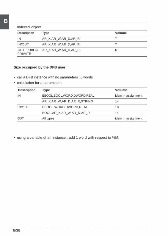
8/36___________________________________________________________________________
BIndexed object
Description Type Volume
IN AR_X,AR_W,AR_D,AR_R, 7
IN/OUT AR_X,AR_W,AR_D,AR_R, 7
OUT, PUBLIC AR_X,AR_W,AR_D,AR_R, 6PRIVATE
Size occupied by the DFB user
• call a DFB instance with no parameters : 6 words
• calculation for a parameter :
Description Type Volume
IN EBOOL,BOOL,WORD,DWORD,REAL idem := assignment
AR_X,AR_W,AR_D,AR_R,STRING 14
IN/OUT EBOOL,WORD,DWORD,REAL 10
BOOL,AR_X,AR_W,AR_D,AR_R, 14
OUT All types idem := assignment
• using a variable of an instance : add 1 word with respect to %M.
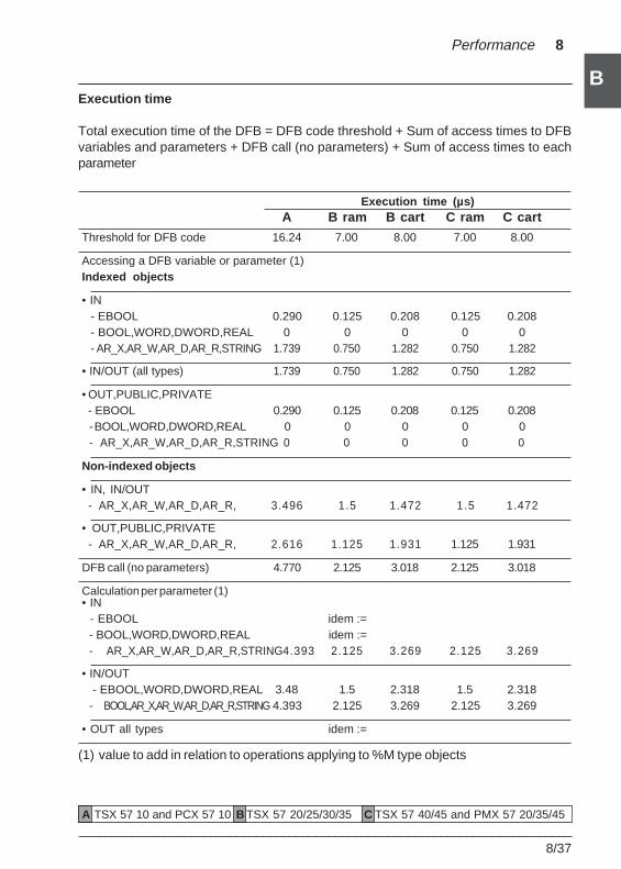
___________________________________________________________________________8/37
B
B
Performance 8
Execution time
Total execution time of the DFB = DFB code threshold + Sum of access times to DFBvariables and parameters + DFB call (no parameters) + Sum of access times to eachparameter
Execution time (µs)A B ram B cart C ram C cart
Threshold for DFB code 16.24 7.00 8.00 7.00 8.00
Accessing a DFB variable or parameter (1)Indexed objects
• IN- EBOOL 0.290 0.125 0.208 0.125 0.208- BOOL,WORD,DWORD,REAL 0 0 0 0 0- AR_X,AR_W,AR_D,AR_R,STRING 1.739 0.750 1.282 0.750 1.282
• IN/OUT (all types) 1.739 0.750 1.282 0.750 1.282
• OUT,PUBLIC,PRIVATE - EBOOL 0.290 0.125 0.208 0.125 0.208
- BOOL,WORD,DWORD,REAL 0 0 0 0 0- AR_X,AR_W,AR_D,AR_R,STRING 0 0 0 0 0
Non-indexed objects
• IN, IN/OUT - AR_X,AR_W,AR_D,AR_R, 3.496 1.5 1.472 1.5 1.472
• OUT,PUBLIC,PRIVATE - AR_X,AR_W,AR_D,AR_R, 2.616 1.125 1.931 1.125 1.931
DFB call (no parameters) 4.770 2.125 3.018 2.125 3.018
Calculation per parameter (1)• IN - EBOOL idem :=
- BOOL,WORD,DWORD,REAL idem :=- AR_X,AR_W,AR_D,AR_R,STRING4.393 2.125 3.269 2.125 3.269
• IN/OUT - EBOOL,WORD,DWORD,REAL 3.48 1.5 2.318 1.5 2.318- BOOL,AR_X,AR_W,AR_D,AR_R,STRING 4.393 2.125 3.269 2.125 3.269
• OUT all types idem :=
(1) value to add in relation to operations applying to %M type objects
A TSX 57 10 and PCX 57 10 B TSX 57 20/25/30/35 C TSX 57 40/45 and PMX 57 20/35/45
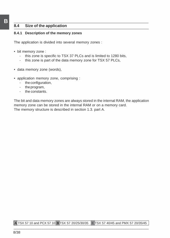
8/38___________________________________________________________________________
B8.4 Size of the application
8.4.1 Description of the memory zones
The application is divided into several memory zones :
• bit memory zone :- this zone is specific to TSX 37 PLCs and is limited to 1280 bits,- this zone is part of the data memory zone for TSX 57 PLCs,
• data memory zone (words),
• application memory zone, comprising :- the configuration,- the program,- the constants.
The bit and data memory zones are always stored in the internal RAM, the applicationmemory zone can be stored in the internal RAM or on a memory card.The memory structure is described in section 1.3. part A.
A TSX 57 10 and PCX 57 10 B TSX 57 20/25/30/35 C TSX 57 40/45 and PMX 57 20/35/45
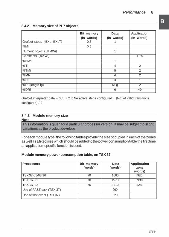
___________________________________________________________________________8/39
B
B
Performance 8
8.4.2 Memory size of PL7 objects
Bit memory Data Application(in words) (in words) (in words)
Grafcet steps (%Xi, %Xi.T) 0.5 1
%Mi 0.5
Numeric objects (%MWi) 1
Constants (%KWi) 1.25
%NWi 1
%Ti 4 2
%TMi 5 2
%MNi 4 2
%Ci 3 1
%Ri (length lg) 6+lg 2
%DRi 6 49
Grafcet interpreter data = 355 + 2 x No active steps configured + (No. of valid transitionsconfigured) / 2
8.4.3 Module memory sizeNoteThis information is given for a particular processor version. It may be subject to slightvariations as the product develops.
For each module type, the following tables provide the size occupied in each of the zonesas well as a fixed size which should be added to the power consumption table the first timean application-specific function is used.
Module memory power consumption table, on TSX 37
Processors Bit memory Data Applica tion(words) (words) zone
(words)TSX 37-05/08/10 70 1560 920
TSX 37-21 70 1570 930
TSX 37-22 70 2110 1280
Use of FAST task (TSX 37) 260
Use of first event (TSX 37) 520
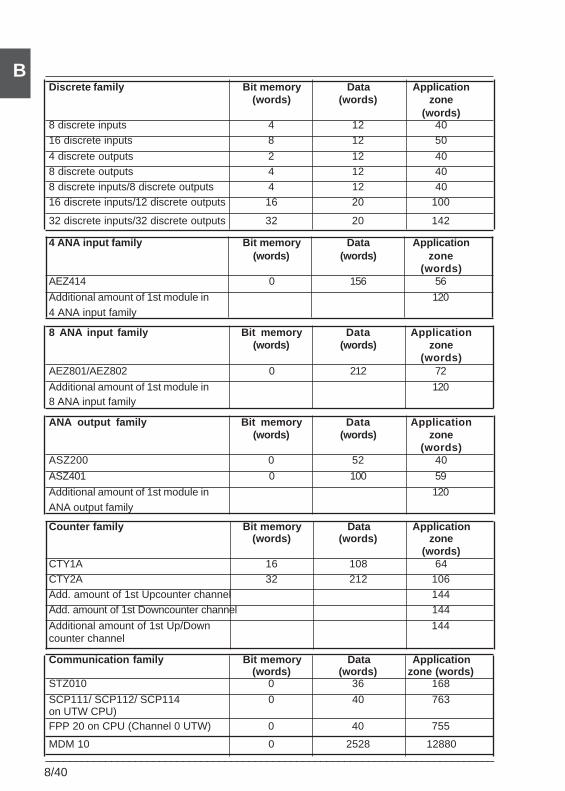
8/40___________________________________________________________________________
BDiscrete family Bit memory Data Application
(words) (words) zone(words)
8 discrete inputs 4 12 4016 discrete inputs 8 12 50
4 discrete outputs 2 12 408 discrete outputs 4 12 408 discrete inputs/8 discrete outputs 4 12 4016 discrete inputs/12 discrete outputs 16 20 100
32 discrete inputs/32 discrete outputs 32 20 142
4 ANA input family Bit memory Data Application(words) (words) zone
(words)AEZ414 0 156 56
Additional amount of 1st module in 1204 ANA input family
8 ANA input family Bit memory Data Application(words) (words) zone
(words)AEZ801/AEZ802 0 212 72
Additional amount of 1st module in 1208 ANA input family
ANA output family Bit memory Data Application(words) (words) zone
(words)ASZ200 0 52 40
ASZ401 0 100 59
Additional amount of 1st module in 120ANA output family
Counter family Bit memory Data Application(words) (words) zone
(words)CTY1A 16 108 64CTY2A 32 212 106Add. amount of 1st Upcounter channel 144Add. amount of 1st Downcounter channel 144
Additional amount of 1st Up/Down 144counter channel
Communication family Bit memory Data Application(words) (words) zone (words)
STZ010 0 36 168
SCP111/ SCP112/ SCP114 0 40 763on UTW CPU)FPP 20 on CPU (Channel 0 UTW) 0 40 755
MDM 10 0 2528 12880
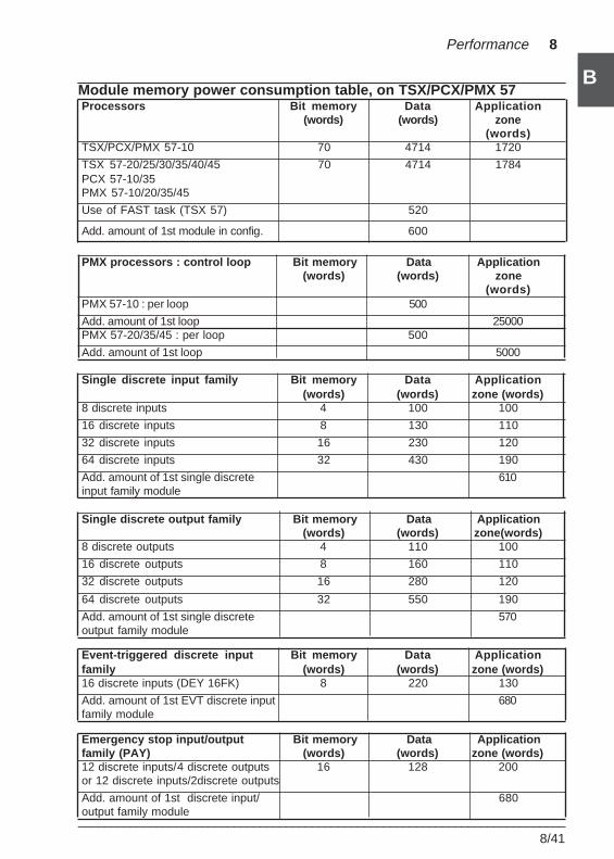
___________________________________________________________________________8/41
B
B
Performance 8
Module memory power consumption table, on TSX/PCX/PMX 57Processors Bit memory Data Application
(words) (words) zone(words)
TSX/PCX/PMX 57-10 70 4714 1720
TSX 57-20/25/30/35/40/45 70 4714 1784PCX 57-10/35PMX 57-10/20/35/45
Use of FAST task (TSX 57) 520
Add. amount of 1st module in config. 600
PMX processors : control loop Bit memory Data Application(words) (words) zone
(words)PMX 57-10 : per loop 500
Add. amount of 1st loop 25000PMX 57-20/35/45 : per loop 500
Add. amount of 1st loop 5000
Single discrete input family Bit memory Data Application(words) (words) zone (words)
8 discrete inputs 4 100 100
16 discrete inputs 8 130 110
32 discrete inputs 16 230 120
64 discrete inputs 32 430 190
Add. amount of 1st single discrete 610input family module
Single discrete output family Bit memory Data Application(words) (words) zone(words)
8 discrete outputs 4 110 100
16 discrete outputs 8 160 110
32 discrete outputs 16 280 120
64 discrete outputs 32 550 190
Add. amount of 1st single discrete 570output family module
Event-triggered discrete input Bit memory Data Applicationfamily (words) (words) zone (words)16 discrete inputs (DEY 16FK) 8 220 130
Add. amount of 1st EVT discrete input 680family module
Emergency stop input/output Bit memory Data Applicationfamily (PAY) (words) (words) zone (words)12 discrete inputs/4 discrete outputs 16 128 200or 12 discrete inputs/2discrete outputs
Add. amount of 1st discrete input/ 680output family module
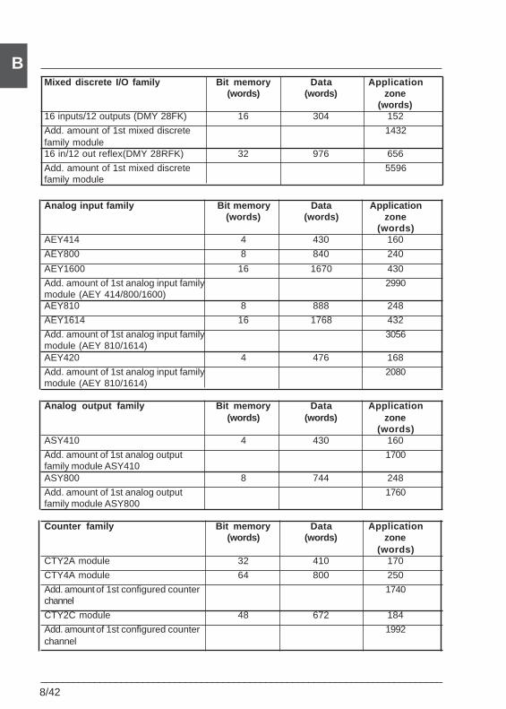
8/42___________________________________________________________________________
BMixed discrete I/O family Bit memory Data Application
(words) (words) zone(words)
16 inputs/12 outputs (DMY 28FK) 16 304 152
Add. amount of 1st mixed discrete 1432family module16 in/12 out reflex(DMY 28RFK) 32 976 656
Add. amount of 1st mixed discrete 5596family module
Analog input family Bit memory Data Application(words) (words) zone
(words)AEY414 4 430 160
AEY800 8 840 240
AEY1600 16 1670 430
Add. amount of 1st analog input family 2990module (AEY 414/800/1600)AEY810 8 888 248
AEY1614 16 1768 432
Add. amount of 1st analog input family 3056module (AEY 810/1614)AEY420 4 476 168
Add. amount of 1st analog input family 2080module (AEY 810/1614)
Analog output family Bit memory Data Application(words) (words) zone
(words)ASY410 4 430 160
Add. amount of 1st analog output 1700family module ASY410ASY800 8 744 248
Add. amount of 1st analog output 1760family module ASY800
Counter family Bit memory Data Application(words) (words) zone
(words)CTY2A module 32 410 170
CTY4A module 64 800 250
Add. amount of 1st configured counter 1740channel
CTY2C module 48 672 184
Add. amount of 1st configured counter 1992channel
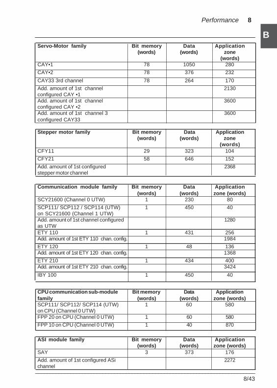
___________________________________________________________________________8/43
B
B
Performance 8
Servo-Motor family Bit memory Data Application(words) (words) zone
(words)CAY•1 78 1050 280
CAY•2 78 376 232
CAY33 3rd channel 78 264 170
Add. amount of 1st channel 2130configured CAY •1Add. amount of 1st channel 3600configured CAY •2Add. amount of 1st channel 3 3600configured CAY33
Stepper motor family Bit memory Data Application(words) (words) zone
(words)CFY11 29 323 104
CFY21 58 646 152
Add. amount of 1st configured 2368stepper motor channel
Communication module family Bit memory Data Application(words) (words) zone (words)
SCY21600 (Channel 0 UTW) 1 230 80
SCP111/ SCP112 / SCP114 (UTW) 1 450 40on SCY21600 (Channel 1 UTW)Add. amount of 1st channel configured 1280as UTWETY 110 1 431 256Add. amount of 1st ETY 110 chan. config. 1984
ETY 120 1 48 136Add. amount of 1st ETY 120 chan. config. 1368
ETY 210 1 434 400Add. amount of 1st ETY 210 chan. config. 3424
IBY 100 1 450 40
CPU communication sub-module Bit memory Data Applicationfamily (words) (words) zone (words)SCP111/ SCP112/ SCP114 (UTW) 1 60 580on CPU (Channel 0 UTW)FPP 20 on CPU (Channel 0 UTW) 1 60 580
FPP 10 on CPU (Channel 0 UTW) 1 40 870
ASI module family Bit memory Data Application(words) (words) zone (words)
SAY 3 373 176
Add. amount of 1st configured ASi 2272channel
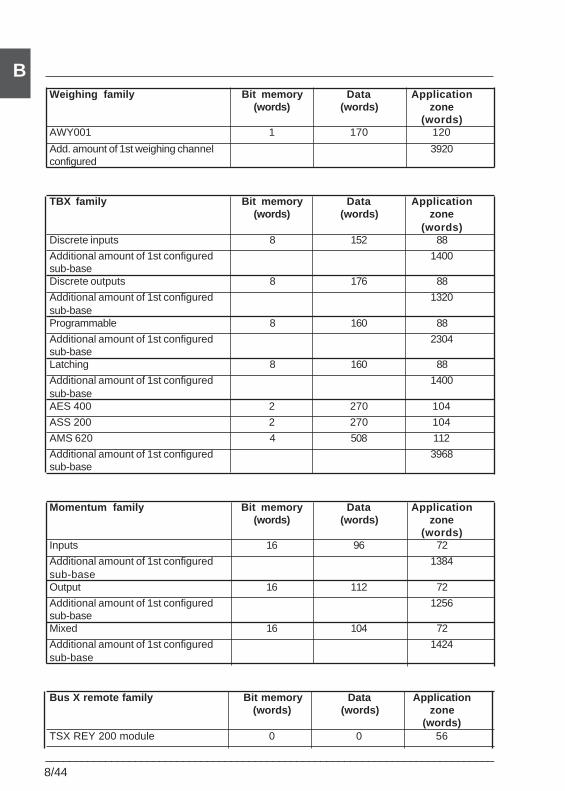
8/44___________________________________________________________________________
BWeighing family Bit memory Data Application
(words) (words) zone(words)
AWY001 1 170 120
Add. amount of 1st weighing channel 3920configured
TBX family Bit memory Data Application(words) (words) zone
(words)Discrete inputs 8 152 88
Additional amount of 1st configured 1400sub-baseDiscrete outputs 8 176 88
Additional amount of 1st configured 1320sub-baseProgrammable 8 160 88
Additional amount of 1st configured 2304sub-baseLatching 8 160 88
Additional amount of 1st configured 1400sub-baseAES 400 2 270 104
ASS 200 2 270 104
AMS 620 4 508 112
Additional amount of 1st configured 3968sub-base
Momentum family Bit memory Data Application(words) (words) zone
(words)Inputs 16 96 72
Additional amount of 1st configured 1384sub-baseOutput 16 112 72
Additional amount of 1st configured 1256sub-baseMixed 16 104 72
Additional amount of 1st configured 1424sub-base
Bus X remote family Bit memory Data Application(words) (words) zone
(words)TSX REY 200 module 0 0 56
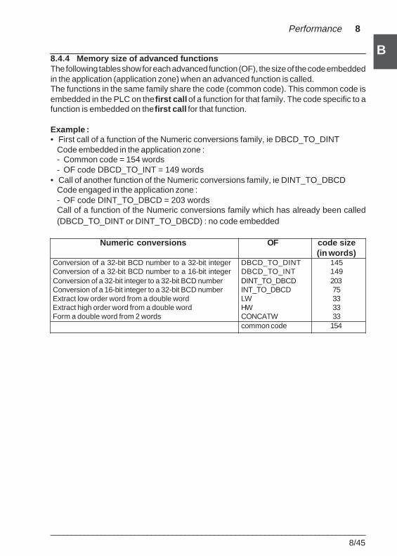
___________________________________________________________________________8/45
B
B
Performance 8
8.4.4 Memory size of advanced functionsThe following tables show for each advanced function (OF), the size of the code embeddedin the application (application zone) when an advanced function is called.The functions in the same family share the code (common code). This common code isembedded in the PLC on the first call of a function for that family. The code specific to afunction is embedded on the first call for that function.
Example :• First call of a function of the Numeric conversions family, ie DBCD_TO_DINT
Code embedded in the application zone :- Common code = 154 words- OF code DBCD_TO_INT = 149 words
• Call of another function of the Numeric conversions family, ie DINT_TO_DBCDCode engaged in the application zone :- OF code DINT_TO_DBCD = 203 wordsCall of a function of the Numeric conversions family which has already been called(DBCD_TO_DINT or DINT_TO_DBCD) : no code embedded
Numeric conversions OF code size(in words)
Conversion of a 32-bit BCD number to a 32-bit integer DBCD_TO_DINT 145Conversion of a 32-bit BCD number to a 16-bit integer DBCD_TO_INT 149Conversion of a 32-bit integer to a 32-bit BCD number DINT_TO_DBCD 203Conversion of a 16-bit integer to a 32-bit BCD number INT_TO_DBCD 75Extract low order word from a double word LW 33Extract high order word from a double word HW 33Form a double word from 2 words CONCATW 33
common code 154
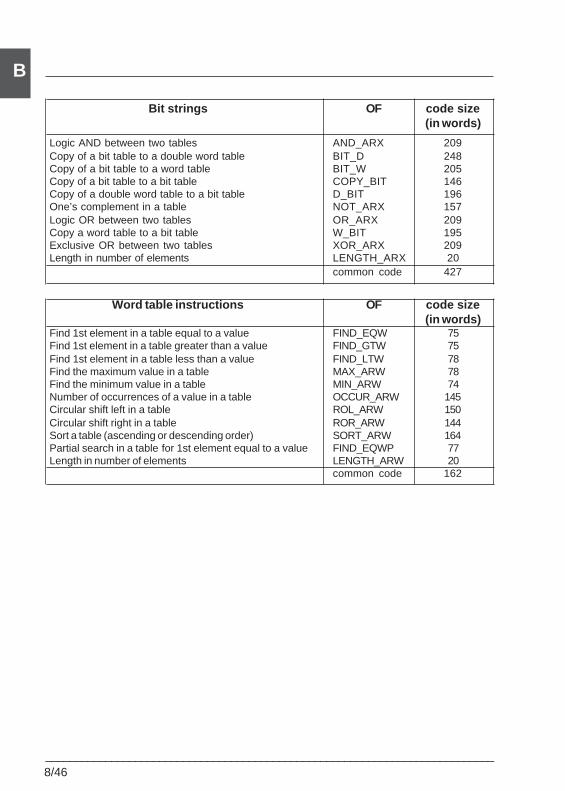
8/46___________________________________________________________________________
B
Bit strings OF code size(in words)
Logic AND between two tables AND_ARX 209Copy of a bit table to a double word table BIT_D 248Copy of a bit table to a word table BIT_W 205Copy of a bit table to a bit table COPY_BIT 146Copy of a double word table to a bit table D_BIT 196One’s complement in a table NOT_ARX 157Logic OR between two tables OR_ARX 209Copy a word table to a bit table W_BIT 195Exclusive OR between two tables XOR_ARX 209Length in number of elements LENGTH_ARX 20
common code 427
Word table instructions OF code size(in words)
Find 1st element in a table equal to a value FIND_EQW 75Find 1st element in a table greater than a value FIND_GTW 75Find 1st element in a table less than a value FIND_LTW 78Find the maximum value in a table MAX_ARW 78Find the minimum value in a table MIN_ARW 74Number of occurrences of a value in a table OCCUR_ARW 145Circular shift left in a table ROL_ARW 150Circular shift right in a table ROR_ARW 144Sort a table (ascending or descending order) SORT_ARW 164Partial search in a table for 1st element equal to a value FIND_EQWP 77Length in number of elements LENGTH_ARW 20
common code 162
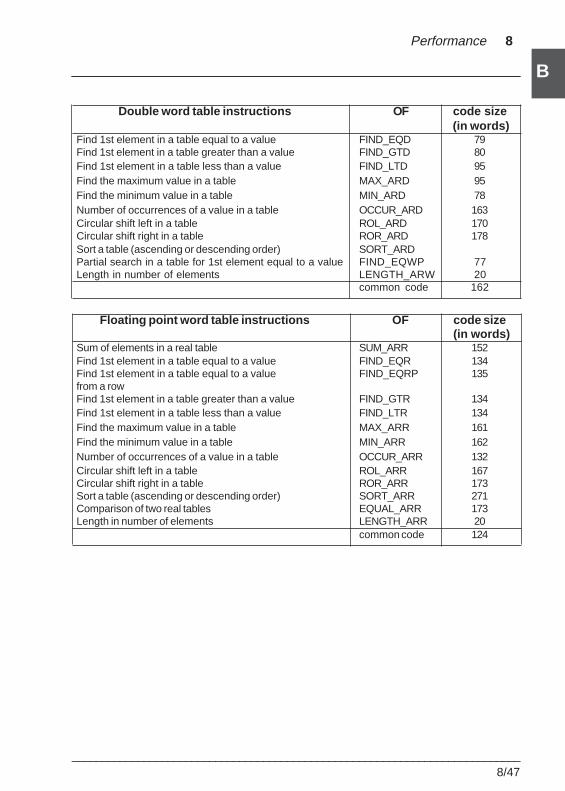
___________________________________________________________________________8/47
B
B
Performance 8
Double word table instructions OF code size (in words)
Find 1st element in a table equal to a value FIND_EQD 79Find 1st element in a table greater than a value FIND_GTD 80Find 1st element in a table less than a value FIND_LTD 95Find the maximum value in a table MAX_ARD 95Find the minimum value in a table MIN_ARD 78Number of occurrences of a value in a table OCCUR_ARD 163Circular shift left in a table ROL_ARD 170Circular shift right in a table ROR_ARD 178Sort a table (ascending or descending order) SORT_ARDPartial search in a table for 1st element equal to a value FIND_EQWP 77Length in number of elements LENGTH_ARW 20
common code 162
Floating point word table instructions OF code size (in words)
Sum of elements in a real table SUM_ARR 152Find 1st element in a table equal to a value FIND_EQR 134Find 1st element in a table equal to a value FIND_EQRP 135from a rowFind 1st element in a table greater than a value FIND_GTR 134Find 1st element in a table less than a value FIND_LTR 134Find the maximum value in a table MAX_ARR 161Find the minimum value in a table MIN_ARR 162Number of occurrences of a value in a table OCCUR_ARR 132Circular shift left in a table ROL_ARR 167Circular shift right in a table ROR_ARR 173Sort a table (ascending or descending order) SORT_ARR 271Comparison of two real tables EQUAL_ARR 173Length in number of elements LENGTH_ARR 20
common code 124
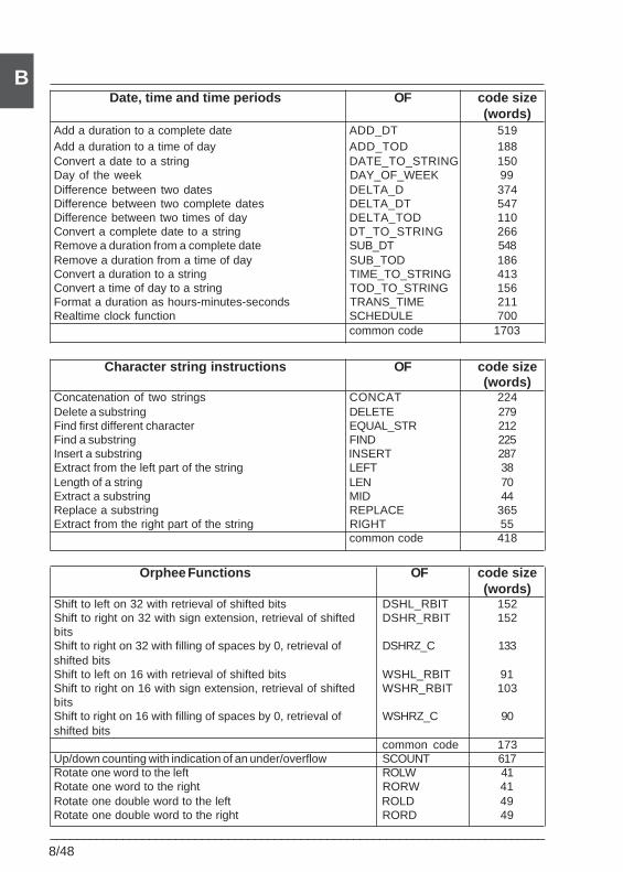
8/48___________________________________________________________________________
BDate, time and time periods OF code size
(words)Add a duration to a complete date ADD_DT 519Add a duration to a time of day ADD_TOD 188Convert a date to a string DATE_TO_STRING 150Day of the week DAY_OF_WEEK 99Difference between two dates DELTA_D 374Difference between two complete dates DELTA_DT 547Difference between two times of day DELTA_TOD 110Convert a complete date to a string DT_TO_STRING 266Remove a duration from a complete date SUB_DT 548Remove a duration from a time of day SUB_TOD 186Convert a duration to a string TIME_TO_STRING 413Convert a time of day to a string TOD_TO_STRING 156Format a duration as hours-minutes-seconds TRANS_TIME 211Realtime clock function SCHEDULE 700
common code 1703
Character string instructions OF code size(words)
Concatenation of two strings CONCAT 224Delete a substring DELETE 279Find first different character EQUAL_STR 212Find a substring FIND 225Insert a substring INSERT 287Extract from the left part of the string LEFT 38Length of a string LEN 70Extract a substring MID 44Replace a substring REPLACE 365Extract from the right part of the string RIGHT 55
common code 418
Orphee Functions OF code size(words)
Shift to left on 32 with retrieval of shifted bits DSHL_RBIT 152Shift to right on 32 with sign extension, retrieval of shifted DSHR_RBIT 152bitsShift to right on 32 with filling of spaces by 0, retrieval of DSHRZ_C 133shifted bitsShift to left on 16 with retrieval of shifted bits WSHL_RBIT 91Shift to right on 16 with sign extension, retrieval of shifted WSHR_RBIT 103bitsShift to right on 16 with filling of spaces by 0, retrieval of WSHRZ_C 90shifted bits
common code 173Up/down counting with indication of an under/overflow SCOUNT 617Rotate one word to the left ROLW 41Rotate one word to the right RORW 41Rotate one double word to the left ROLD 49Rotate one double word to the right RORD 49
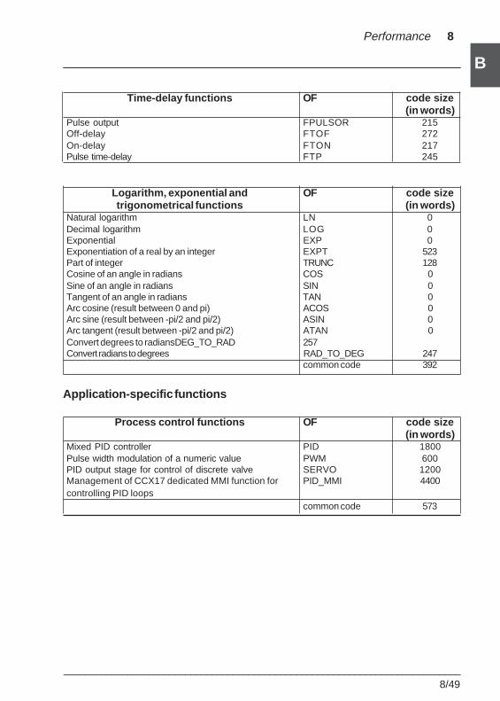
___________________________________________________________________________8/49
B
B
Performance 8
Time-delay functions OF code size(in words)
Pulse output FPULSOR 215Off-delay FTOF 272On-delay FTON 217Pulse time-delay FTP 245
Logarithm, exponential and OF code sizetrigonometrical functions (in words)
Natural logarithm LN 0Decimal logarithm LOG 0Exponential EXP 0Exponentiation of a real by an integer EXPT 523Part of integer TRUNC 128Cosine of an angle in radians COS 0Sine of an angle in radians SIN 0Tangent of an angle in radians TAN 0Arc cosine (result between 0 and pi) ACOS 0Arc sine (result between -pi/2 and pi/2) ASIN 0Arc tangent (result between -pi/2 and pi/2) ATAN 0Convert degrees to radiansDEG_TO_RAD 257Convert radians to degrees RAD_TO_DEG 247
common code 392
Application-specific functions
Process control functions OF code size(in words)
Mixed PID controller PID 1800Pulse width modulation of a numeric value PWM 600PID output stage for control of discrete valve SERVO 1200Management of CCX17 dedicated MMI function for PID_MMI 4400controlling PID loops
common code 573
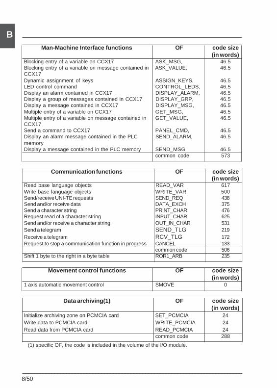
8/50___________________________________________________________________________
BMan-Machine Interface functions OF code size
(in words)Blocking entry of a variable on CCX17 ASK_MSG, 46.5Blocking entry of a variable on message contained in ASK_VALUE, 46.5CCX17Dynamic assignment of keys ASSIGN_KEYS, 46.5LED control command CONTROL_LEDS, 46.5Display an alarm contained in CCX17 DISPLAY_ALARM, 46.5Display a group of messages contained in CCX17 DISPLAY_GRP, 46.5Display a message contained in CCX17 DISPLAY_MSG, 46.5Multiple entry of a variable on CCX17 GET_MSG, 46.5Multiple entry of a variable on message contained in GET_VALUE, 46.5CCX17Send a command to CCX17 PANEL_CMD, 46.5Display an alarm message contained in the PLC SEND_ALARM, 46.5memoryDisplay a message contained in the PLC memory SEND_MSG 46.5
common code 573
Communication functions OF code size(in words)
Read base language objects READ_VAR 617Write base language objects WRITE_VAR 500Send/receive UNI-TE requests SEND_REQ 438Send and/or receive data DATA_EXCH 375Send a character string PRINT_CHAR 476Request read of a character string INPUT_CHAR 625Send and/or receive a character string OUT_IN_CHAR 531Send a telegram SEND_TLG 219Receive a telegram RCV_TLG 172Request to stop a communication function in progress CANCEL 133
common code 506Shift 1 byte to the right in a byte table ROR1_ARB 235
Movement control functions OF code size(in words)
1 axis automatic movement control SMOVE 0
Data archiving(1) OF code size(in words)
Initialize archiving zone on PCMCIA card SET_PCMCIA 24Write data to PCMCIA card WRITE_PCMCIA 24Read data from PCMCIA card READ_PCMCIA 24
common code 288
(1) specific OF, the code is included in the volume of the I/O module.
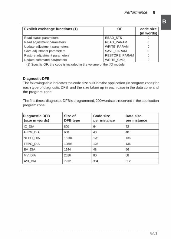
___________________________________________________________________________8/51
B
B
Performance 8
Explicit exchange functions (1) OF code size(in words)
Read status parameters READ_STS 0Read adjustment parameters READ_PARAM 0Update adjustment parameters WRITE_PARAM 0Save adjustment parameters SAVE_PARAM 0Restore adjustment parameters RESTORE_PARAM 0Update command parameters WRITE_CMD 0
(1) Specific OF, the code is included in the volume of the I/O module.
Diagnostic DFBThe following table indicates the code size built into the application (in program zone) foreach type of diagnostic DFB and the size taken up in each case in the data zone andthe program zone.
The first time a diagnostic DFB is programmed, 200 words are reserved in the applicationprogram zone.
Diagnostic DFB Size of Code size Data size (size in words) DFB type per instance per instance
IO_DIA 800 64 72
ALRM_DIA 608 40 48
NEPO_DIA 15184 128 136
TEPO_DIA 10896 128 136
EV_DIA 1144 48 56
MV_DIA 2616 80 88
ASI_DIA 7912 304 312
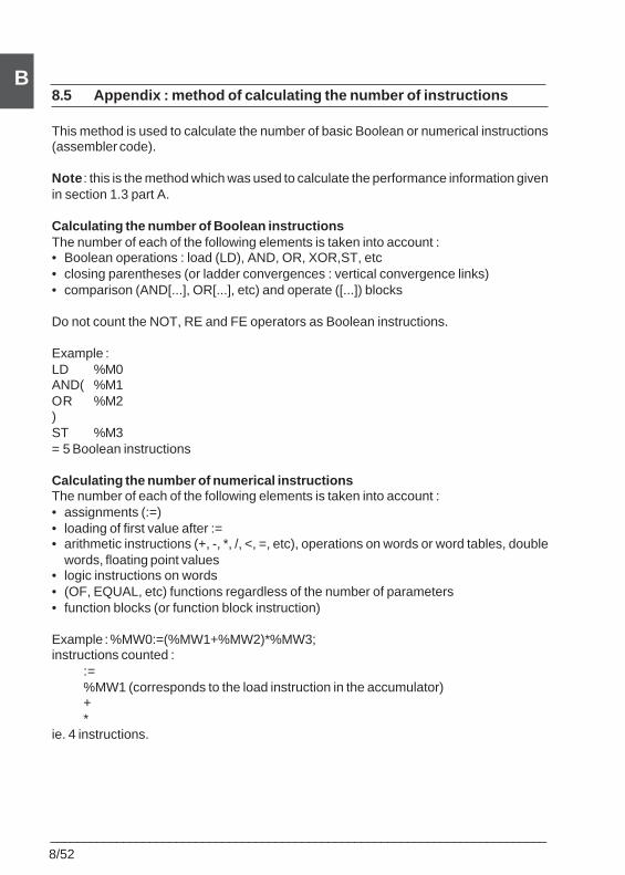
8/52___________________________________________________________________________
B8.5 Appendix : method of calculating the number of instructions
This method is used to calculate the number of basic Boolean or numerical instructions(assembler code).
Note : this is the method which was used to calculate the performance information givenin section 1.3 part A.
Calculating the number of Boolean instructionsThe number of each of the following elements is taken into account :• Boolean operations : load (LD), AND, OR, XOR,ST, etc• closing parentheses (or ladder convergences : vertical convergence links)• comparison (AND[...], OR[...], etc) and operate ([...]) blocks
Do not count the NOT, RE and FE operators as Boolean instructions.
Example :LD %M0AND( %M1OR %M2)ST %M3= 5 Boolean instructions
Calculating the number of numerical instructionsThe number of each of the following elements is taken into account :• assignments (:=)• loading of first value after :=• arithmetic instructions (+, -, *, /, <, =, etc), operations on words or word tables, double
words, floating point values• logic instructions on words• (OF, EQUAL, etc) functions regardless of the number of parameters• function blocks (or function block instruction)
Example : %MW0:=(%MW1+%MW2)*%MW3;instructions counted :
:=%MW1 (corresponds to the load instruction in the accumulator)+*
ie. 4 instructions.
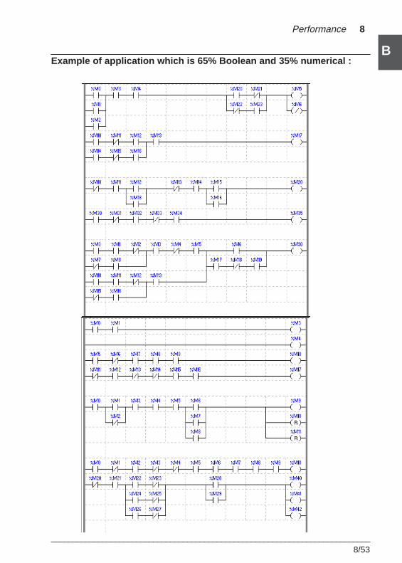
___________________________________________________________________________8/53
B
B
Performance 8
Example of application which is 65% Boolean and 35% numerical :
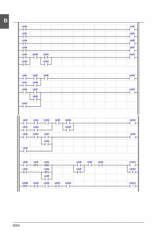
8/54___________________________________________________________________________
B
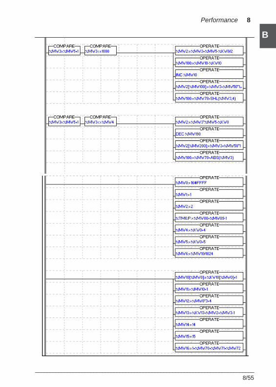
___________________________________________________________________________8/55
B
B
Performance 8
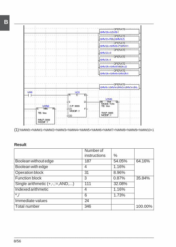
8/56___________________________________________________________________________
B
(1):%MW0:=%MW1+%MW2+%MW3+%MW4+%MW5+%MW6+%MW7+%MW8+%MW9+%MW10+1
ResultNumber ofinstructions %
Boolean without edge 187 54.05% 64.16%Boolean with edge 4 1.16%Operation block 31 8.96%Function block 3 0.87% 35.84%Single arithmetic (+,-,:=,AND,...) 111 32.08%Indexed arithmetic 4 1.16%*,/ 6 1.73%Immediate values 24Total number 346 100.00%
OLE Automation Server 9
___________________________________________________________________________
9/1
B
Section 99 OLE Automation Server
9.1 Presentation
9.1-1 Warning
Knowledge of one of the following languages is required when creating a clientapplication for the OLE server for OLE Automation programming :
• Microsoft Visual Basic, version 5.0 or later
• Microsoft Visual C++, version 4.2 or later
• Microsoft VBA in Excel, version 5.0 or later
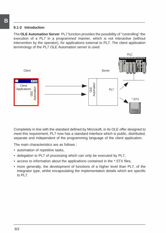
9/2
___________________________________________________________________________
B9.1-2 Introduction
The OLE Automation Server PL7 function provides the possibility of "controlling" theexecution of a PL7 in a programmed manner, which is not interactive (withoutintervention by the operator), for applications external to PL7. The client applicationterminology of the PL7 OLE Automation server is used.
PL7
ServerClient
ClientApplications
OLE
Aut
omat
ion
OLE
Aut
omat
ion
PLC
*.STX
Completely in line with the standard defined by Microsoft, in its OLE offer designed tomeet this requirement, PL7 now has a standard interface which is public, distributed,separate and independent of the programming language of the client application.
The main characteristics are as follows :
• automation of repetitive tasks,
• delegation to PL7 of processing which can only be executed by PL7,
• access to information about the applications contained in the *.STX files,
• more generally, the development of functions of a higher level than PL7, of theintegrator type, whilst encapsulating the implementation details which are specificto PL7.
OLE Automation Server 9
___________________________________________________________________________
9/3
B9.1-3 Execution context
The PL7 OLE Automation server function is integrated in PL7 Pro. It is installed andexecuted under the same installation and execution conditions as PL7.The PL7 OLE Automation server is based on Microsoft OLE Automation run-timeprovided with Windows 95, 98 and NT.
9.1-4 Operating modes
In addition to the PL7 operating mode known to date, which is referred to as "interactive"and in which the PL7 responds exclusively to operator entries, there is now the OLEAutomation server operating mode in which PL7 also responds to commands sent byan OLE client application.
The choice of operating mode depends on the PL7 start procedure. Interactive modeis initialized when PL7 is started via Windows (Start/Programs/Modicon Telemecanique/PL7 Pro menu).Server mode is chosen if the PL7 OLE Automation server is called in the programmingof an OLE client application. An instance cannot change mode while it is in progress.
Each time a client application calls the PL7 OLE Automation server, a specific instanceof PL7 is started, independently of other instances which may already have beenstarted. Any number of PL7 instances in server or interactive mode may be executedon the same station. The instances are completely independent of one another, andeach can be executed in its own context.
For all these instances, the same exclusion rules regarding concurrent access to anSTX application or a PLC apply, namely : an STX application or a PLC may only bemanipulated by one instance at a time.
This rule has been adapted for the PL7 OLE Automation server, which may open anSTX application which is already open but which cannot be saved. Likewise, inresponse to an explicit request, it can carry out a PLC —> PC transfer from a PLCreserved elsewhere.A client application may instantiate several "PL7 OLE Automation servers" at the sametime.
9/4
___________________________________________________________________________
B9.2 Implementation
9.2-1 Installation
The installation of the PL7 OLE Automation Server product is transparent for the user,and is performed implicitly during the installation of PL7.The installation comprises :
1. Four examples of OLE Automation client, complete with source code, and a READMEfile are provided in the software.
These examples correspond to :
• a "minimum" Visual C++ 4.2 client : the minimum required in order to write an OLEclient,
• a "complete" Visual C++ 4.2 client which uses all the available input points,
• a Visual Basic 5.0 client which uses all the available input points,
• an Excel client.
2. An *.h file which defines the value of the error codes returned by the server.
3. A TLB interface file for a Visual C++ client.
9.2-2 Starting the server in offline mode (COM mode)
COM mode (Component Object Model) defines an interface for communicationbetween applications. It provides independence in relation to the development tools.To communicate with the server application, the client application declares an “A”object.It is then sufficient to execute the Createdispatch function on the “A” object of the clientapplication in order to instantiate the server application.
The server is located transparently for the client application in the Createdispatch byinterrogating the register base.
The link between the client application and the server application is created if the latteris referenced in the register base. In order to ensure that the PL7 Pro applicationoperates correctly in server mode, when installing the product it is necessary to saveit as an OLE server in the register base.
The client application is now able to interrogate the server application via the interfaceaccessible from the “A” object.Example :A.OpenStx(“C:\appli.stx”)
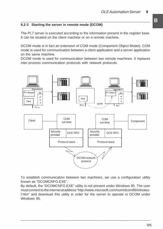
OLE Automation Server 9
___________________________________________________________________________
9/5
B9.2-3 Starting the server in remote mode (DCOM)
The PL7 server is executed according to the information present in the register base.It can be located on the client machine or on a remote machine.
DCOM mode is in fact an extension of COM mode (Component Object Model). COMmode is used for communication between a client application and a server applicationon the same machine.DCOM mode is used for communication between two remote machines. It replacesinter-process communication protocols with network protocols.
ClientCOM
run-timeCOM
run-time Component
Securityprovider
DCE RPC
Protocol stack
Securityprovider
DCE RPC
Protocol stack
DCOM networkprotocol
To establish communication between two machines, we use a configuration utilityknown as “DCOMCNFG.EXE”.By default, the “DCOMCNFG.EXE” utility is not present under Windows 95. The usermust connect to the internet at address “http://www.microsoft.com/com/dcom95/relnotes-f.htm” and download this utility in order for the server to operate in DCOM underWindows 95.
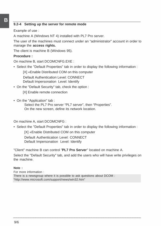
9/6
___________________________________________________________________________
B9.2-4 Setting up the server for remote mode
Example of use :
A machine A (Windows NT 4) installed with PL7 Pro server.
The user of the machines must connect under an “administrator” account in order tomanage the access rights.
The client is machine B (Windows 95).
Procedure :
On machine B, start DCOMCNFG.EXE :
• Select the "Default Properties" tab in order to display the following information :
[X] «Enable Distributed COM on this computer
Default Authentication Level: CONNECT Default Impersonation Level: Identify
• On the "Default Security" tab, check the option :
[X] Enable remote connection
• On the "Application" tab :Select the PL7 Pro server “PL7 server”, then “Properties”.On the new screen, define its network location.
On machine A, start DCOMCNFG :
• Select the "Default Properties" tab in order to display the following information :
[X] «Enable Distributed COM on this computer
Default Authentication Level: CONNECTDefault Impersonation Level: Identify
"Client" machine B can control "PL7 Pro Server " located on machine A.
Select the "Default Security" tab, and add the users who will have write privileges onthe machine.
Note :For more information :There is a newsgroup where it is possible to ask questions about DCOM :“http://www.microsoft.com/support/news/win32.htm”
OLE Automation Server 9
___________________________________________________________________________
9/7
B9.3 PL7 server execution modes
The PL7 OLE Automation Server has two execution modes, which can be selecteddynamically during execution (see SetIHMServer ) :
• Execution mode without HMI. The PL7 is started as a “background task”, with nodisplay or possibility of operator entry. This mode is typically used, for example,to automate repetitive tasks or to access data about an application contained inan stx file.
• Execution mode with HMI. PL7 is started as an "interactive" PL7 with display and thepossibility of operator entry, but it remains receptive to commands sent by its clientapplication. This mode has been developed in order to display program or configu-ration elements of an application contained in an stx file, from external tools such asDIAG Viewer.
Notes :Services regarding the display of programs, tools or modules can only be executed in the modewith HMI.
In its mode with HMI, the PL7 OLE Automation Server is subject to user rights checks. It ispositioned in the “Read Only” user rights profile, which corresponds to its role of displaying PL7I/O code and modules.
In its mode without HMI, the PL7 OLE Automation Server is not subject to user rights checks,but the services offered do not allow the application to be modified.
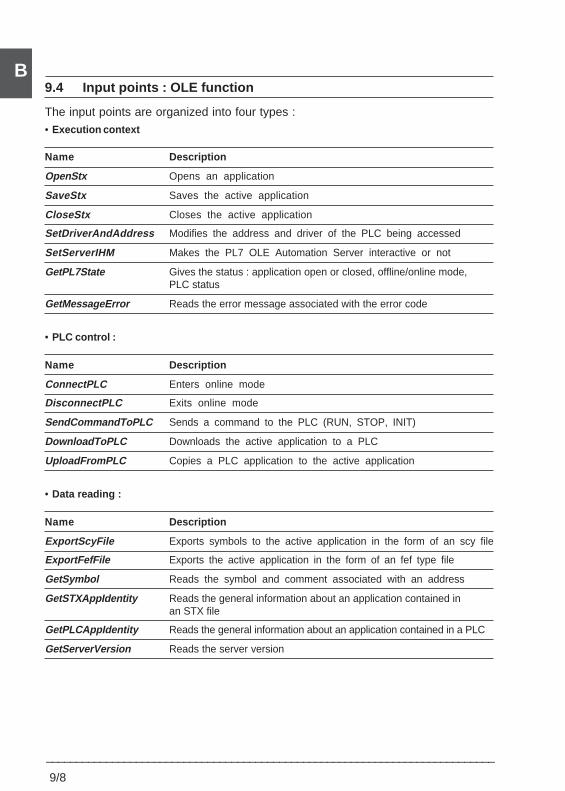
9/8
___________________________________________________________________________
B9.4 Input points : OLE function
The input points are organized into four types :• Execution context
Name Description
OpenStx Opens an application
SaveStx Saves the active application
CloseStx Closes the active application
SetDriverAndAddress Modifies the address and driver of the PLC being accessed
SetServerIHM Makes the PL7 OLE Automation Server interactive or not
GetPL7State Gives the status : application open or closed, offline/online mode,PLC status
GetMessageError Reads the error message associated with the error code
• PLC control :
Name Description
ConnectPLC Enters online mode
DisconnectPLC Exits online mode
SendCommandToPLC Sends a command to the PLC (RUN, STOP, INIT)
DownloadToPLC Downloads the active application to a PLC
UploadFromPLC Copies a PLC application to the active application
• Data reading :
Name Description
ExportScyFile Exports symbols to the active application in the form of an scy file
ExportFefFile Exports the active application in the form of an fef type file
GetSymbol Reads the symbol and comment associated with an address
GetSTXAppIdentity Reads the general information about an application contained inan STX file
GetPLCAppIdentity Reads the general information about an application contained in a PLC
GetServerVersion Reads the server version
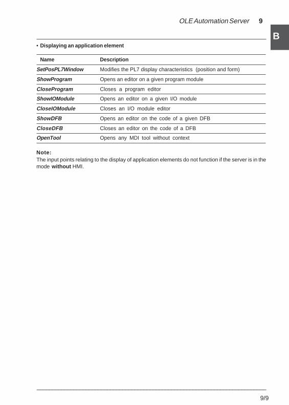
OLE Automation Server 9
___________________________________________________________________________
9/9
B• Displaying an application element
Name Description
SetPosPL7Window Modifies the PL7 display characteristics (position and form)
ShowProgram Opens an editor on a given program module
CloseProgram Closes a program editor
ShowIOModule Opens an editor on a given I/O module
CloseIOModule Closes an I/O module editor
ShowDFB Opens an editor on the code of a given DFB
CloseDFB Closes an editor on the code of a DFB
OpenTool Opens any MDI tool without context
Note:The input points relating to the display of application elements do not function if the server is in themode without HMI.
9/10
___________________________________________________________________________
B9.5 Description of OLE functions
9.5-1 OpenStx
This function is used to open an stx application file.Syntax : integer OpenStx(String lpAppPathName).
• Input :Enter the character string containing the name of the file the user wishes to open.
• Function called :OpenStation : Station management function (gesta.dll).
• Nominal contextThe PL7 server is active.
• In the event of an error :SRV_ERR_GEN_FILENOTFOUND : The file has not been found.SRV_ERR_OPEN_BADZIP : File decompression problem.SRV_ERR_OPEN_BADFILE : Problem reading the stx fileSRV_ERR_OPEN_NOK_COMPATIBLE : The processor is not compatible
with the open PL7.SRV_ERR_OPEN_OPEN : An application is already open.
SRV_ERR_GEN_PARAM_EMPTY : The path name is empty.
SRV_ERR_GEN_ACTION : Error opening the application.
SRV_ERR_GEN_DRIVE FULL : No more free space on the diskfor opening the application.
• Output :Short type return code. Either 0 if the application has been opened successfully, oran error code.
9.5-2 CloseStx
This function is used to close the current application.Syntax : integer CloseStx(integer p_bWithoutSave).
• Input :If the application has been modified, it is possible to close it without warning the user(p_bWithoutSave a TRUE)
• Function called :CloseStation : Station management function (gesta.dll).
• Nominal context :The PL7 server is active, an application is open.
OLE Automation Server 9
___________________________________________________________________________
9/11
B• In the event of an error :
SRV_ERR_GEN_NOTOPEN : No application is open.SRV_ERR_CLOSE_NOTSAVE: The application has been modified, it must be
saved in order to exit.
• Output :Short type return code. Either 0 if the application has been closed successfully, oran error code.
9.5-3 ExportScyFile
This function is used to export the symbols contained in the active application in theform of an scy file.Syntax : integer ExportScyFile(String p_psScyFile)
• Input:Enter the character string containing the name of the scy file.
• Function called :ExportScyFile : Station management function (gesta.dll).
• Nominal context :The PL7 server is active.An application is open.
• In the event of an error :SRV_ERR_GEN_ACTION : Error during the creation of the symbol
source file.SRV_ERR_GEN_NOTOPEN: No application is open.SRV_ERR_GEN_PARAM_EMPTY : p_ psScyFile is empty
SRV_EXPORT_ERRFILE Error writing the source file.
• Output :Short type return code. Either 0 in the case of a successful export, or an error code.
9/12
___________________________________________________________________________
B9.5-4 ExportFefFile
This function is used to export the active application in the form of an fef file.Syntax : integer ExportFefFile(String p_psNamefile)
• Input :Enter the character string containing the name of the fef file.
• Function called :ExportFefFile : Station management function (gesta.dll).
• Nominal context :The PL7 server is active.An application is open.
• In the event of an error :SRV_ERR_GEN_ACTION : Error during the creation of the application
source file.SRV_ERR_GEN_NOTOPEN: No application is open.SRV_ERR_GEN_PARAM_EMPTY : p_psNamefile is empty.
SRV_EXPORT_ERRFILE Error writing the source file.
• Output :Short type return code. Either 0 in the case of a successful export, or an error code.
9.5-5 DisconnectPLC
This function is used for disconnecting the PLC and PL7.Syntax : integer DisconnectPLC ()
• Function called :DisconnectStation : Station management function (gesta.dll).
• Nominal context :The PL7 server is active.
• Output :Short type return code. Either 0 in the case of a successful disconnection, or an errorcode (SRV_ERR_GEN_ACTION).
OLE Automation Server 9
___________________________________________________________________________
9/13
B9.5-6 ConnectPLC
This function is used for connecting to a PLC.Syntax : integer ConnectPLC(String p_lpDriver, String p_lpAddress)
• Input :Enter two character strings containing the driver and address of the PLC.
• Function called :ConnectStation : Station management function (gesta.dll).
• Nominal contextThe PL7 server is active.If the parameters are empty strings, the server executes the function using the currentdriver and/or address.
• In the event of an error :SRV_ERR_GEN_CONNECT : Connection was not possible.
SRV_ERR_GEN_COMMUNICATION : Communication problem between PL7 Proand the PLC.
SRV_ERR_GEN_RESERVED : The PLC is reserved; it is thereforeimpossible to connect to it.
SRV_ERR_PLC_BLANK : The PLC does not contain an application;connection is therefore impossible.
SRV_ERR_PC_BLANK : No application is open; connectionis therefore impossible.
SRV_ERR_DIFFERENCE_PLC_STX : The open application and the applicationcontained in the PLC are different;connection is therefore impossible.
SRV_ERR_GEN_ADDRESS : The address parameter is incorrect.
SRV_ERR_GEN_ACTION : Error during the execution of the function.
SRV_ERR_GEN_DRIVER: The driver parameter is incorrect.
SRV_ERR_GEN_NOTOPEN : No application is open.
SRV_ERR_GEN_PROTECTEDAPPLI : Protected application.
SRV_COMPATIBLE_PLC : Compatibility problem with the PLC.
• OutputShort type return code. Either 0 in the case of successful connection, or an error code.
9/14
___________________________________________________________________________
B9.5-7 SaveStx
This function is used to save the open application.Syntax : integer SaveStx(String p_lpStxFile)
• Input :Enter a character string containing the path and name of the backup file.
• Function called :SaveStx : Station management function (gesta.dll).
• Nominal context :The PL7 server is active.An application is open, PL7 is in offline mode.
• In the event of an error :
SRV_ERR_SAVEDENIED : Access to file refused.
SRV_ERR_SAVEERRZIP : Error when compressing the application.
SRV_ERR_SAVEERRREN : Renaming refused.
SRV_ERR_GEN_NOTOPEN : No application is open.
SRV_ERR_GEN_PARAM_EMPTY : p_ lpStxFile is empty.
SRV_ERR_GEN_ACTION : Error saving the application.
SRV_ERR_PLC_CONNECT : Saving can only be carried out inoffline mode.
• Output :Short type return code. Either 0 if the application has been saved successfully, or anerror code.
9.5-8 DownloadToPLC
This function is used to download an application to the PLC memory.Syntax : integer DownloadToPLC(String p_lpDriver, String p_lpAdresse)
• Input :Enter two character strings containing the driver and address of the PLC.
• Function called :DownloadStation: Station management function (gesta.dll).
• Nominal context :The PL7 server is active.An application is open, PL7 is in offline mode.If the parameters are empty strings, the server executes the function using the currentdriver and/or address.
OLE Automation Server 9
___________________________________________________________________________
9/15
B• In the event of an error :
SRV_ERR_DOWNLOAD_CART : Memory card compatibility problembetween the open application and the PLC.
SRV_ERR_COMPATIBLE_PLC : Compatibility problem between the openapplication and the PLC.
SRV_ERR_GEN_ADDRESS : The p_lpAdresse parameter is incorrect.
SRV_ERR_GEN_DRIVER : The p_lpDriver parameter is incorrect.
SRV_ERR_GEN_NOTOPEN : No application is open.
SRV_ERR_GEN_RESERVED : The PLC is reserved.
SRV_ERR_GEN_COMMUNICATION : Communication problem.
SRV_ERR_PLC_CONNECT : The PLC is already connected.
SRV_ERR_PLC_ACTION : Download error.
• OutputShort type return code. Either 0 in the case of a successful download, or an error code.
9.5-9 UploadfromPLC
This function is used to copy an application contained in a PLC to the memory.Syntax : integer UploadFromPLC(String p_lpDriver, String p_lpAdresse, integerp_iReservedMode)
• Input :Enter two character strings containing the driver and address of the PLC.An integer (p_iReservedMode) making it possible to carry out an Upload on areserved PLC.
• Function called :
UploadStation : Station management function (gesta.dll).
• Nominal context :The PL7 server is active.No application is open, and PL7 is in offline mode.If the parameters are empty strings, the server executes the function using the currentdriver and/or address.
9/16
___________________________________________________________________________
B• In the event of an error :
SRV_ERR_UPLOAD_TRANSFER : Problem transferring the applicationcontained in the PLC.
SRV_ERR_UPLOAD_ABORT : Suspension of the transfer.
SRV_ERR_UPLOAD_RESERVED : Application reserved.
SRV_ERR_UPLOAD_NOAPPLI : No application on PLC.
SRV_ERR_GEN_ADDRESS : Incorrect address.
SRV_ERR_GEN_ACTION : Error during the execution of the function.
SRV_ERR_PLC_CONNECT : Connection error.
SRV_ERR_GEN_DRIVER : Incorrect driver.
SRV_ERR_GEN_COMMUNICATION : Communication error.
SRV_ERR_PLC_CONNECT : The PLC is in online mode.
SRV_OPEN_NOT_COMPATIBLE : Compatibility problem.
• Output :Short type return code. Either 0 in the case of a successful upload, or an error code.
9.5-10 GetSymbol
This function is used to provide the symbol and comment associated with an address.Syntax : integer GetSymbol(String p_lpRepere, String* p_bsSymbole, String*p_bsComment)
• Input :Enter the character string containing the address to be modified or entered.
• Function called :
GetSymbol : Station management function (gesta.dll).
• Nominal context :
The PL7 server is active.An application is open and in offline mode.
• In the event of an error :
SRV_ERR_ADDRESSSYNTAX : The character string entered as a parameterdoes not correspond to an address.
SRV_ERR_GEN_NOTOPEN : No application is open.
SRV_ERR_GEN_PARAM_EMPTY : p_lpRepere is empty.
SRV_ERR_GEN_ACTION : Error during the execution of the function.
OLE Automation Server 9
___________________________________________________________________________
9/17
B• Output :
Short type return code. Either 0 in the case of a successful load, or an error code.- Two character strings : The associated symbol (p_bsSymbole). The associated comment (p_bsComment).
9.5-11 SetServerIHM
This function is used to display or hide the PL7 server. It performs the transition fromone operating mode to the other, namely from a PL7 Pro server without HMI to a PL7Pro server with HMI and vice versa.Syntax : integer SetServerIHM (integer p_bIHM)
• Input :A Boolean (stating whether to display HMI or not).
• Function called :SetIHMServer : Function of the Windows application (sawinapp.cpp).
• Nominal context :The PL7 server is active.
• In the event of an error :SRV_ERR_GEN_ACTION: Error during the execution of the function.
SRV_ERR_GEN_MODIFAPPLI :Application being modified.
• Output :Short type return code. Either 0 in the case of a successful load, or an error code.
9/18
___________________________________________________________________________
B9.5-12 GetPL7State
This function provides the state of the server.Syntax : integer GetPL7State(String* p_lpStation, String * p_lpConnection)
• Function called :GetPL7State : Station management function (gesta.dll).
• Nominal context :The PL7 server is active.
• In the event of an error :SRV_ERR_GEN_ACTION : Error during the execution of the function.
• Output :Short type return code. Either 0 in the case of a successful load, or an error code.Two character strings provide the user with information about :- The station state (open or closed).- The mode state (offline or online). In online mode, the PLC status (run or stop) isindicated.
9.5-13 GetSTXAppIdentity
This function is used to find out the general information about an application.Syntax : integer GetSTXAppIdentity(String p_lpNameStx, VARIANT FAR* p_pVarInfo)
• Input :
Enter the character string (p_lpNameStx) containing the name of the application.
• Function called :
FicheIdentAppli: Station management function (gesta.dll).
• Nominal context :
The PL7 server is active.
• In the event of an error :SRV_ERR_GEN_PARAM_EMPTY : p_ lpNameStx is empty.
SRV_ERR_GEN_ACTION : Error during the execution of the function.
SRV_ERR_APPLIINFO_NOK : Incorrect information.
OLE Automation Server 9
___________________________________________________________________________
9/19
B• Output :
Short type return code. Either 0 in the case of a successful load, or an error code.Information displayed :
1 The station name,2 Date and time of creation,3 The station ID,4 The ID for the configuration of the local I/O,5 The ID for the configuration of the remote I/O,6 The ID for the PL7 code,7 The ID for Grafcet,8 The ID for the constants,9 The ID for the symbols,10 The ID for the reservation,11 The comment associated with the application.
9.5-14 GetPLCAppIdentity
This function is used to find out the general information about an application containedin a PLC.Syntax : integer GetPLCAppIdentity(String p_lpDriver, String p_lpAdresse, VARIANTFAR* p_pvInfoAppli)
• Input :Enter the two character strings containing the driver and address of the PLC.
• Function called :FicheIdentAppliOnAutomate : Station management function (gesta.dll).
• Nominal context :
The PL7 server is active and in offline mode.
• In the event of an error :
SRV_ERR_APPLIINFO_NOK : Incorrect information.
SRV_ERR_GEN_ACTION : Error during the execution of the function.
SRV_ERR_GEN_ADDRESS : Incorrect address.
SRV_ERR_COMPATIBLE_PLC : Compatibility problem between the PLC and thePL7 software.
SRV_ERR_PLC_BLANK : There is no application in the PLC.
SRV_ERR_GEN_ACTION : Problem saving the application data.
SRV_ERR_GEN_DRIVER : The p_lpDriver parameter is incorrect.
SRV_ERR_GEN_COMMUNICATION : Communication error.
9/20
___________________________________________________________________________
B• Output
Short type return code. Either 0 in the case of a successful load, or an error code.
Information displayed :1 The station name,2 Date and time of creation,3 The station ID,4 The ID for the configuration of the local I/O,5 The ID for the configuration of the remote I/O,6 The ID for the PL7 code,7 The ID for Grafcet,8 The ID for the constants,9 The ID for the symbols,10 The ID for the reservation,11 The comment associated with the application.
9.5-15 SendCommandToPLC
This function is used to send a command to the PLC.Syntax : integer SendCommandToPLC(integer p_iCommand)
• Input :The type of command the user wishes to execute.There are 3 possible types :SRV_COMMAND_INIT : PLC initialization commandSRV_COMMAND_STOP : Stop commandSRV_COMMAND_RUN : Run command
• Function called :StationCommand : Station management function (gesta.dll).
• Nominal contextThe PL7 server is active. An application is open; PL7 is in online mode, in STOP.
• In the event of an error :
SRV_ERR_GEN_ACTION : Incorrect command.
SRV_ERR_GEN_NOTOPEN : No application is open.
SRV_ERR_COMMAND_NOTINLOCAL : The server is in offline mode.
SRV_COMMAND_ERRINIT : The INIT function is impossible, the PLC is in RUN.
• Output :
Short type return code. Either 0 in the case of a successful load, or an error code.
OLE Automation Server 9
___________________________________________________________________________
9/21
B9.5-16 SetDriverAndAdresse
This function is used to change the driver and address of the current station.Syntax : integer SetDriverAndAdresse(String p_lpDriver, String p_lpAdresse)
• Input :
Enter the two character strings containing the driver and address of the PLC.
• Function called :
DriverAndAdresse: Station management function (gesta.dll).
• Nominal context :
The PL7 server is active.An application is open and in offline mode.If the parameters are not entered or are incorrect, the current values remainunchanged.
• In the event of an error :
SRV_ERR_GEN_ADDRESS : The address entered as a parameter is incorrect.
SRV_ERR_GEN_DRIVER : The driver entered as a parameter is incorrect.
SRV_ERR_PLC_CONNECT : The server is in online mode.
SRV_ERR_PLC_ACTION : Error during the execution of the function.
SRV_ERR_PARAM_EMPTY : The parameters are empty.
• Output :
Short type return code. Either 0 in the case of a successful load, or an error code.
9.5-17 OpenTool
This function is used to open the tools present in the character string entered as aparameter.Syntax : integer OpenTool(String p_lpListTool))
• Input :Character strings containing the list of tools which the server must open.Format example : tools1;tools2;tools3
• Function called :OpenTool : Station management function (gesta.dll).
9/22
___________________________________________________________________________
B• Nominal context :
The PL7 server with HMI is active.An application is open.
• In the event of an error :
SRV_ERR_GEN_ACTION : Impossible to open the tool.SRV_ERR_GEN_PARAM_EMPTY : Parameter empty.SRV_ERR_GEN_NOTOPEN : No application is open.
SRV_ERR_GEN_WITHIHM : Function available with the PL7 serverin HMI mode.
SRV_ERR_GEN_OPENEDTVDATA : The "Animation table" tool cannot be opened.
• Output :Short type return code. Either 0 in the case of a successful load, or an error code.
9.5-18 SetPosPL7Windows
This function is used to size the PL7 window.Syntax : integer PosPL7Windows(integer CoordX, integer CoordY, integer CoordCX,integer CoordCY)
• Input :
The x, y coordinates of the window.
• Function called :
MoveWindow : Mfc function.
• Nominal context :
The PL7 server with HMI is active.
• In the event of an error :
SRV_ERR_GEN_ACTION : Command failed.SRV_ERR_GEN_PARAM_EMPTY : Parameter empty.
SRV_ERR_GEN_WITHIHM : Function available with the PL7 serverin HMI mode.
• Output :Short type return code.
OLE Automation Server 9
___________________________________________________________________________
9/23
B9.5-19 ShowProgram
This function is used to open the programs present in the character string entered asa parameter.Syntax : integer ShowProgram(String p_lpListProgram)
• Input :Enter the character strings containing the list of programs which the server must open.Format example : mast\lad1;mast\lit2;evt\evt0;sr1;mast\prl
• Function called :ShowProgram : Station management function (gesta.dll).
• Nominal context :The PL7 server with HMI is active.An application is open.
• In the event of an error :
SRV_ERR_GEN_ACTION : Command failed.
SRV_ERR_GEN_NOTOPEN : No application is open.
SRV_ERR_GEN_PARAM_EMPTY : Parameter empty.
SRV_ERR_GEN_WITHIHM : Function available with the PL7 serverin HMI mode.
SRV_ERR_GEN_SHOWPROGRAM : Impossible to open the module.
• Output :Short type return code. Either 0 in the case of a successful load, or an error code.
• Limitations :This function is not capable of opening an uninstantiated DFB. To display the codeof an uninstantiated DFB, use the ShowDFB function.
9.5-20 CloseProgram
This function is used to close the programs present in the character string entered asa parameter.Syntax : integer CloseProgram(String p_lpListProgram)
• Input :Character strings containing the list of programs which the server must close.Format example : mast\lad1;mast\lit2;evt\evt0;sr1;mast\prl.
9/24
___________________________________________________________________________
B• Function called :
CloseProgram : Station management function (gesta.dll).
• Nominal context :The PL7 server with HMI is active.An application is open.
• In the event of an error :SRV_ERR_GEN_NOTOPEN : No application is open.
SRV_ERR_GEN_ACTION : Close failed.
SRV_ERR_GEN_PARAM_EMPTY : Parameter empty.
SRV_ERR_GEN_WITHIHM : Function available with the PL7 serverin HMI mode.
SRV_ERR_GEN_CLOSEPROGRAMM : Impossible to close the module.
• Output :Short type return code. Either 0 in the case of a successful load, or an error code.
• Limitations :This function is not capable of closing an open DFB.
9.5-21 ShowIOModule
This function is used to open the I/O modules present in the character string enteredas a parameter.
• Input :Character strings containing the list of modules which the server must open.The format of the character string is rack,module;rack,moduleFormat example : 0,0;0,1;1,2
• Function called :ShowIOModule : Station management function (gesta.dll).
• Nominal context :The PL7 Pro server with HMI is active.An application is open.
• In the event of an error :SRV_ERR_GEN_NOTOPEN : No application is open.
SRV_ACTION_NOK : Problem with activating the user rights.
SRV_ERR_GEN_PARAM_EMPTY : Parameter empty.
SRV_ERR_GEN_WITHIHM : Function available with the PL7 server
OLE Automation Server 9
___________________________________________________________________________
9/25
Bin HMI mode.
• Output :Short type return code. Either 0 in the case of a successful load, or an error code.
• Limitations :An I/O module is opened in offline mode; the module configuration screen is open.If the user changes from offline mode to online mode, the server does not change fromthe configuration screen to the debug screen. The user can either operate directlyon the PL7 Pro, or open/close the module using the client.
9.5-22 CloseIOModule
This function is used to close the I/O modules present in the character string enteredas a parameter.Syntax : integer CloseIOModule(String p_lpListIOModule).
• Input :Character strings containing the list of modules which the server must open.Format example : 0,0;0,1;1,2
• Function called :CloseIOModule : Station management function (gesta.dll).
• Nominal context :The PL7 server with HMI is active.An application is open.
• In the event of an error :SRV_ERR_GEN_ACTION : Close command failed.SRV_ERR_GEN_PARAM_EMPTY : Parameter empty.SRV_ERR_GEN_NOTOPEN : No application is open.SRV_ERR_GEN_WITHIHM : Function available with the PL7 server
in HMI mode.
• Output : Short type return code. Either 0 in the case of a successful load, or an error code.
• Limitations :This function does not close the configuration editor opened using the functionShowIOModule.
9/26
___________________________________________________________________________
B9.5-23 ShowDFB
This function is used to display the code of one or more DFBs present in the characterstring entered as a parameter. Opening a DFB via this function does not requireinstantiation.Syntax : integer ShowDFB(String p_lpListeDFB).
• Input :Character strings containing the list of DFBs which the server must open.
• Function called :ShowDFB : Station management function (gesta.dll).
• Nominal context :The PL7 server with HMI is active.An application is open.
• In the event of an error :SRV_ERR_GEN_PARAM_EMPTY : Parameter empty.SRV_ERR_GEN_NOTOPEN : No application is open.SRV_ERR_GEN_ACTION : Problem opening a DFB.
SRV_ERR_GEN_WITHIHM : Function available with the PL7 serverin HMI mode.
• OutputShort type return code. Either 0 in the case of a successful load, or an error code.
9.5-24 CloseDFB
This function is used to close one or more DFBs present in the character string enteredas a parameter.Syntax : integer CloseDFB(String p_lpListeDFB)
• Input :Character strings containing the list of DFBs which the server must close.
• Function called :CloseDFB : Station management function (gesta.dll).
• Nominal context :The PL7 server with HMI is active.An application is open.
OLE Automation Server 9
___________________________________________________________________________
9/27
B• In the event of an error :
SRV_ERR_GEN_PARAM_EMPTY : Parameter empty.
SRV_ERR_GEN_NOTOPEN : No application is open.
SRV_ERR_GEN_ACTION : Problem closing a DFB.
SRV_ERR_GEN_WITHIHM : Function available with the PL7 serverin HMI mode.
• OutputShort type return code. Either 0 in the case of a successful load, or an error code.
9.5-25 GetMessageError
This function is used to associate an error message depending on the error codeentered as a parameter.Syntax : String GetMessageError(integer p_iCodeError)
• Input :The error code of one of the services to be returned.
• Nominal context :The PL7 server is active.
• Output :A character string corresponding to the name of the error.
9.5-26 GetServerVersion
This function is used to find out the version number of the PL7 Pro server.String GetServerVersion()
• Nominal contextThe PL7 server is active.
• OutputA character string corresponding to the name of the version number of the PL7 Proserver.
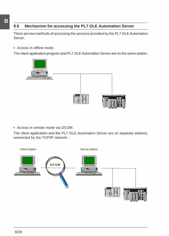
9/28
___________________________________________________________________________
B9.6 Mechanism for accessing the PL7 OLE Automation Server
There are two methods of accessing the services provided by the PL7 OLE AutomationServer.
• Access in offline mode.
The client application program and PL7 OLE Automation Server are on the same station.
• Access in remote mode via DCOM.
The client application and the PL7 OLE Automation Server are on separate stations,connected by the TCP/IP network :
Client station Server station
DCOM
Index 9
___________________________________________________________________________10/1
B
INDEX10 Index
Symbols%Ci B 1/14%DRi B 2/9%Li B 1/30%MNi B 2/2%Ri B 2/5%Ti B 2/13%TMi B 1/10* B 1/23+ B 1/23- B 1/23/ B 1/23:= B 1/20< B 1/19<= B 1/19<> B 1/19= B 1/19> B 1/19>= B 1/19
AABS B 1/23Absolute value B 1/23ACOS B 2/26Action zone A 2/1Actions A 5/17ADD_DT B 2/80ADD_TOD B 2/81Addition B 1/23Addressing A 1/11Addressing TSX 37 objects A 1/11Addressing TSX 57 objects A 1/13Alphanumeric comparisons B 2/53AND B 1/6, B 1/25AND convergences A 5/4AND divergences A 5/4AND_ARX B 2/93ANDF B 1/6ANDN B 1/6ANDR B 1/6Arithmetic on integers B 1/23ASCII ---> Binary conversion B 2/56ASCII --> Floating point conversion B 2/58ASIN B 2/26Assignment B 1/20ATAN B 2/26
BBCD <--> Binary conversion B 2/29Binary --->ASCII conversion B 2/54Bit memory A 1/26, A 1/29Bit tables A 1/21, B 2/92BIT_D B 2/94BIT_W B 2/94Bits A 1/10BLK A 3/8Boolean instructions B 1/2Byte A 1/16
CCALL A 2/3Character string A 1/21, B 2/51Circular shift B 2/19Cold restart A 1/38Comments A 2/6, A 3/4, A 4/7, A 5/14Common words A 1/18Comparison B 1/19Complement B 1/25CONCAT B 2/59Concatenation of two strings B 2/59CONCATW B 2/34Constant A 1/16Control structures A 4/9Conversion B 2/28, B 2/29Conversions ASCII ---> Binaire B 2/112COPY_BIT B 2/92COS B 2/26Cyclic execution A 1/41
DD_BIT B 2/96DATE_TO_STRING B 2/86Dates B 2/72DAY_OF_WEEK B 2/79DEC B 1/23Decrement B 1/23DEG_TO_RAD B 2/28DELETE B 2/60DELTA_D B 2/83DELTA_DT B 2/84DELTA_TOD B 2/85Destination connector A 5/5DFB A 1/9, A6/1
10/2___________________________________________________________________________
BDFB instance A6/8DFB objects A6/3DFB type A6/3DINT_TO_REAL B 2/32DINT_TO_STRING B 2/54Direct coils B 1/5Directed links A 5/5, A 5/13Division B 1/23Double length A 1/17DOWN B 1/12, B 1/16Downcounter B 1/14Drum controller B 2/9DSHL_RBIT B 2/98DSHR_RBIT B 2/98DSHRZ_C B 2/98DT_TO_STRING B 2/87Durations B 2/72
EEdges A 1/29, B 1/2END B 1/32End of program B 1/32END_BLK A 3/8ENDC B 1/32ENDCN B 1/32EQUAL B 2/41EQUAL_ARR B 2/41EQUAL_STR B 2/69Event masking/unmasking B 1/34Event-triggered tasks A 1/50Exclusive OR B 1/8EXIT A 4/14EXP B 2/25Exponential instructions B 2/25EXPT B 2/25
FFalling edge contacts B 1/4FAST A 1/48Fast task A 1/48FIFO stack B 2/5FIND B 2/70Find in tables B 2/43FIND_EQD B 2/43FIND_EQW B 2/43FIND_GTD B 2/43FIND_GTW B 2/43FIND_LTD B 2/43
FIND_LTW B 2/43Floating point A 1/17, B 2/20Floating point ---> ASCII conversion B 2/57Floating point instructions B 2/20FOR ... END_FOR A 4/13Forcing A 1/30FPULSOR B 2/109Freezing the Grafcet chart A 5/26FTOF B 2/107FTON B 2/105FTP B 2/108Function block objects A 1/20Function blocks B 1/9Functions on tables B 2/40
GGET B 2/8Grafcet language A 5/1Grafcet objects A 1/23, A 5/6Grafcet section A 5/23Graphic elements, Grafcet A 5/4Graphic elements, Ladder language A 2/2Gray --> Integer conversion B 2/33GRAY_TO_INT B 2/33, B 2/34
HHALT B 1/33HW B 2/34
IIF ... END_IF A 4/9Immediate values A 1/18INC B 1/23Increment B 1/23Index overrun A 1/23Indexation A 1/22Indexed objects A 1/22INSERT B 2/61Instruction List language A 3/1INT_TO_REAL B 2/32INT_TO_STRING B 2/54Integer <--> Floating point conversion B 2/31Internal words A 1/16Inverse coils B 1/5
Index 9
___________________________________________________________________________10/3
BJJMP B 1/30JMPC B 1/30JMPCN B 1/30Jump B 1/30
LLabel A 2/6, A 3/4, A 4/8Ladder language A 2/1LD B 1/4LDF B 1/4LDN B 1/4LDR B 1/4LEFT B 2/67LEN B 2/71LENGTH_ARR B 2/50LIFO stack B 2/5LN B 2/25LOG B 2/25Logarithms B 2/25Logic AND B 1/6Logic OR B 1/7, B 1/25Logic shift B 2/19LW B 2/34
MMacro-step A 5/15MASKEVT B 1/34Master task A 1/47MAX_ARD B 2/45MAX_ARW B 2/45Memory card A 1/26MID B 2/65MIN_ARD B 2/45MIN_ARW B 2/45Monostable B 1/11, B 2/2MPP A 3/7MPS A 3/7MRD A 3/7Multiplication B 1/23Multitask A 1/45
NN/C contacts B 1/4N/O contacts B 1/4NOT B 1/25
NOT_ARX B 2/93Numerical expression B 1/27
OObjects which can be symbolized A 1/24OCCUR_ARD B 2/46OCCUR_ARR B 2/46OCCUR_ARW B 2/46OLE B9/2OLE server B9/2Operating modes A 5/1OR B 1/7, B 1/25OR convergences A 5/5OR_ARX B 2/93ORF B 1/7ORN B 1/7ORR B 1/7OUT_BLK A 3/8Overflow B 1/24
PParentheses A 3/5PCMCIA B 2/111Periodic execution A 1/42Post-processing A 5/30Pre-processing A 5/24PRESET B 1/16Presymbolization A 1/25Private variables A6/4Program instructions B 1/28PTC B 2/78Public variables A6/4PUT B 2/8
RR B 1/5RAD_TO_DEG B 2/28Read day of the week B 2/79Read system date B 2/77READ_PCMCIA B 2/116REAL_TO_DINT B 2/32REAL_TO_INT B 2/32Realtime clock B 2/75Register B 2/5REM B 1/23REPEAT ... END_REPEAT A 4/12REPLACE B 2/63
10/4___________________________________________________________________________
BRESET B 1/16, B 2/8, B 2/11Reset coils B 1/5RET B 1/29RETCN B 1/29RIGHT B 2/67Rising edge contacts B 1/4ROL_ARD B 2/47ROL_ARW B 2/47ROR_ARD B 2/47ROR_ARR B 2/47ROR_ARW B 2/47RRTC B 2/77Rung A 2/5Rungs, execution A 2/13
SS B 1/5SCHEDULE B 2/75SCOUNT B 2/101Section A 1/4, A 1/39Sequence A 3/4Sequence selection A 5/10Sequential processing A 5/28Set coils B 1/5SET_PCMCIA B 2/112Simultaneous step activation A 5/10SIN B 2/26Single task A 1/39Sort function on tables B 2/49, B 2/50SORT_ARD B 2/49SORT_ARR B 2/49SORT_ARW B 2/49Source connector A 5/5SQRT B 1/23Square root B 1/23SRi A 1/39ST B 1/5START B 1/12, B 2/3Steps A 5/4STN B 1/5Stop code B 2/78STRING_TO_DINT B 2/56STRING_TO_INT B 2/56STRING_TO_REAL B 2/58Structured data B 4/4Structured Text language A 4/1SUB_DT B 2/80SUB_TOD B 2/81Subroutine A 1/39, B 1/28
Subroutine return B 1/29Subtraction B 1/23SUM B 2/40SUM_ARR B 2/40Symbol A 1/6, A 1/24System bits B 3/1System words B 3/9
TTable comparisons B 2/41TAN B 2/26Test zone A 2/1Time B 2/72Time delay B 2/105Time of day B 2/72TIME_TO_STRING B 2/88Timer B 1/10, B 2/13, B 2/105, B 2/107 B2/108, B 2/109TOD_TO_STRING B 2/89TRANS_TIME B 2/91Transition conditions A 5/20Transitions A 5/4Trigonometric functions B 2/26TRUNC B 2/24
UUNMASKEVT B 1/34UP B 2/11Upcounter B 1/14Update system date B 2/77User function blocks A 1/9User memory A 1/26
VVertical comparison B 2/17
WW_BIT B 2/96Warm restart A 1/37Watchdog A 1/44WHILE ... END_WHILE A 4/11Word extract bits A 1/18Word memory A 1/26, A 1/27, A 1/31Word tables A 1/21, B 2/35WRITE_PCMCIA B 2/114WRTC B 2/78WSHL_RBIT B 2/98, B 2/103
Index 9
___________________________________________________________________________10/5
BWSHR_RBIT B 2/98WSHRZ_C B 2/98
XXOR B 1/8, B 1/25XOR_ARX B 2/93XORF B 1/8XORN B 1/8XORR B 1/8

10/6___________________________________________________________________________
B