Embed Size (px)
Citation preview

530.18-TG3L (500)
Cont’d.
DESCRIPTION
These units are convertible single package units.All models have dual refrigerant circuits for efficientpart load operation. Although the units are primarilydesigned for curb mounting on a roof, they can alsobe slab-mounted at ground level or set on steelbeams above a finished roof.Cooling only, cooling with gas heat and cooling withelectric heat models are available with severalfactory-mounted options and a wide variety offield-installed accessories to make them suitablefor almost every application.All units are self-contained and assembled on fullperimeter base rails with holes in the four cornersfor overhead rigging.
Every unit is completely piped, wired, charged andtested at the factory to simplify the field installationand to provide years of dependable operation.
All models (including those with an economizer) aresuitable for either bottom or horizontal ductconnections. Models with power exhaust aresuitable for bottom duct connections only. Forbottom duct, you remove the sheet metal panelsfrom the supply and return air openings through thebase of the unit. For horizontal duct, you replace thesupply and return air panels on the rear of the unitwith a side duct flange accessory.
All models are available with three different outdoorair damper options:
• Single enthalpy economizer• Single enthalpy economizer with power exhaust• Motorized outdoor air damperA fixed outdoor air intake assembly is shipped inthe return air compartment of all units orderedwithout an economizer or motorized outdoor airdamper option. The assembly includes a rain hoodwith a damper that can be set for 10, 15 or 25%outdoor air. With bottom duct connections, theintake damper assembly should be mounted overthe opening in the return air panel. With horizontalductwork, it should be mounted on the return airduct.All supply air blowers are equipped with a belt drivethat can be adjusted to meet the exactrequirements of the job. A high speed driveaccessory is available for applications with a higherCFM and/or static pressure requirement.
All compressors include crankcase heat andinternal pressure relief. Every refrigerant circuitincludes an expansion valve, a liquid line filter-drier,a discharge line high pressure switch and a suctionline with a freezestat and low pressure/loss ofcharge switch. The unit control circuit includes a 75VA transformer, a 24-volt circuit breaker and a relayboard with two compressor lockout circuits, aterminal strip for thermostat wiring, plus anadditional set of pin connectors to simplify theinterface of additional field controls.All units have long lasting powder paint cabinetswith 750 hour salt spray test approval underASTM-B117 procedures.
MODEL DHB
MODEL DUC
SINGLE PACKAGEGAS / ELECTRIC UNITS ANDSINGLE PACKAGE AIR CONDITIONERS
DBHB/DBUC 180 & 24015 AND 20 NOMINAL TONS8.5 - 8.7 EER

All gas heat models are built with two heating sections for twoequal stages of capacity control. Each section includes adurable heat exchanger with aluminized steel tubes, aredundant gas valve, spark ignition, power venting, an ignitionmodule for 100% shut-off and all of the safety controls requiredto meet the latest ANSI standards.The gas supply piping can be routed into the heatingcompartment through a hole in the base pan of the unit orthrough a knockout in the piping panel on the front of the unit.All electric heat models are wired for a single power source andinclude a bank of nickel chromium elements mounted at thedischarge of the supply air blower to provide a high velocity anduniform distribution of air across the heating elements. Everyelement is fully protected against excessive current andtemperature by fuses and two thermal limit switches.All internal factory wiring is color coded and numbered for easein servicing and troubleshooting.The power supply wiring can be routed into the control boxthrough a threaded pipe connection in the base pan of the unitor through a knockout in the wiring panel on the front of the unit.
FACTORY-INSTALLED OPTIONS
ECONOMIZERS - Interlocked outdoor and return air dampersare positioned by a fully modulating, spring return damperactuator capable of introducing up to 100% outdoor air withnominal 1% leakage type dampers.. As the outdoor air intakedampers open, the return air dampers close. The changeoverfrom compressor to economizer cooling is determined by asolid state enthalpy control.An outdoor air sensor determines when the outdoor air is cooland dry enough to provide “free” cooling. Whenever the outdoorair is cooler and drier than the return air, the unit will switch toeconomizer operation. The #1 compressor can provideadditional cooling during economizer operation if the roomthermostat calls for second stage.The dampers and controls are installed and wired at the factory.Only the rain hood needs to be assembled and installed in thefield.The economizer option can be used on all duct configurations.MOTORIZED OUTDOOR AIR INTAKE DAMPER - Interlockedoutdoor and return air dampers are controlled by a 2-position,spring return damper actuator. The outdoor damper will opento some pre-set position whenever the supply air blower isoperating and will drive fully closed when the blower shutsdown.The damper and controls are installed and wired at the factory.Only the rain hood needs to be assembled in the field.This damper option can be used on all duct configurations.
FIELD-INSTALLED ACCESSORIES
SINGLE INPUT ELECTRONIC ENTHALPY ECONOMIZERS- Includes a slide-in / plug-in damper assembly with fullymodulating spring-return monitor actuator capable ofintroducing up to 100% outdoor air with nominal 1% leakagetype dampers.
The enthalpy system contains one sensor that monitors theoutdoor air and determines when the air is cool enough anddry enough to provide "free" cooling.The rainhood is painted to match the basic unit and must befield-assembled before installing.On units built prior to January 1995, an accessory field harnessmust be installed.Power exhaust is not available as a field installed option.
DUAL INPUT ELECTRONIC ENTHALPY ECONOMIZERS -Includes a slide-in / plug-in damper assembly with fullymodulating spring-return monitor actuator capable ofintroducing up to 100% outdoor air with nominal 1% leakagetype dampers.This enthalpy system contain one sensor that monitors theoutdoor air and one sensor that monitors the return air. Thelogic module compares these two values and modulates thedampers providing the maximum efficiency of economizersystem.
The rainhood is painted to match the basic unit and must befield-assembled before installing.On units built prior to January 1995, an accessory field harnessmust be installed.Power exhaust is not available as a field installed option.MOTORIZED OUTDOOR AIR INTAKE DAMPER - Includes aslide-in / plug-in damper assembly with a 2-position, springreturn motor actuator which opens to some pre-set positionwhenever the supply air blower is operating and will drive fullyclosed when the blower unit shuts down.The rain hood is painted to match the basic unit and must befield assembled before installing.On units built prior to January 1995 an accessory field harnessmust be installed.
Power exhaust is not available as a field installed option.ROOF CURBS - 14" high roof curbs provide a water-tight sealbetween the unit and the finished roof. These full perimetercurbs meet the requirements of the National RoofingContractors Associat ion (NRCA) and are shippedknocked-down for field assembly. They’re designed to fit insidethe base rails of the unit and include both a wood nailing stripand duct hanger supports.ANTI-RECYCLE TIMERS - Two solid state timers prevent thecompressors from short-cycling. Once a compressor isde-energized, it will remain de-energized for approximately fiveminutes.HIGH ALTITUDE NATURAL GAS - Burner orifices and pilotorifices are provided for proper furnace operation at altitudesup to 6,000 feet.SIDE DUCT FLANGES - 1" flanges replace the supply andreturn air panels on the rear of the unit to accommodatehorizontal duct connections. These flanges can also be usedindividually for bottom supply/horizontal return or horizontalsupply/bottom return.BAROMETRIC RELIEF DAMPER - This damper accessorycan be used to relieve internal air pressure on units with aneconomizer but no power exhaust. This accessory includes arain hood, a bird screen and a fully assembled damper. Withbottom duct connections, the damper should be mounted overthe opening in the return air panel. With horizontal ductwork,the accessory should be mounted on the return air duct.
LOW AMBIENT CONTROLS TO 0°F - An autotransformer anda thermostat maintain stable system operation by reducing thespeed of the #1 condenser fan motor at low outdoortemperatures. The kit also includes a 1-phase motor to replacethe unit’s standard 3-phase condenser fan motor. Standardunits can operate down to 25°F.COIL GAURD KIT - Includes wire coil guard and fasteners. Thecoil gaurd is painted.
TABLE OF CONTENTSPower Exhaust Performance ............................................. 10Field Wiring ........................................................................ 11Electrical Data - Clg. and Gas Heating .............................. 11Electrical Data - Units with Electric Heating ...................... 12Physical Data ..................................................................... 12Unit Dimensions................................................................. 13Roof Curb Dimensions....................................................... 16Typical Applications............................................................ 17
Description ........................................................................... 1Factory-Installed Options..................................................... 2Field-Installed Accessories .................................................. 2Ratings................................................................................. 3Cooling Capacities ............................................................... 4Blower Performance............................................................. 6Blower Motor and Drive Data............................................. 10Static Resistances ................ .............................................10
530.18-TG3L
2 Unitary Products Group
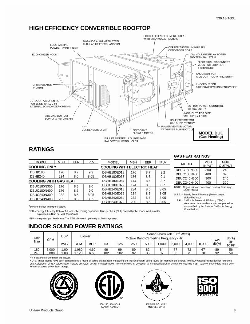
HIGH EFFICIENCY CONVERTIBLE ROOFTOP
208/230, 575 VOLTMODELS ONLY
208/230, 460 VOLTMODELS ONLY
MODEL MBHINPUT
MBHOUTPUT
DBUC180N300 300 240DBUC180N400 400 320DBUC240N300 300 240DBUC240N400 400 320
NOTE: All gas units are two-stage heating. First stage is 50% of total.
S.S.E. = Steady State Efficiency (80%) - output divided by input. S.E. = California Seasonal Efficiency (72%) - determined in accordance with test procedure as specified by the State of California Energy Commission.
MODEL MBH EER IPLV
COOLING ONLYDBHB180 176 8.7 9.2DBHB240 234 8.6 8.05
COOLING WITH GAS HEATDBUC180N300 176 8.5 9.0DBUC180N400 176 8.5 9.0DBUC240N300 232 8.5 8.05DBUC240N400 232 8.5 8.05
MODEL MBH EER IPLV
COOLING WITH ELECTRIC HEATDBHB180E018 176 8.7 9.2DBHB180E036 176 8.6 9.1DBHB180E054 174 8.5 8.7DBHB180E072 174 8.5 8.7DBHB240E018 234 8.5 8.05DBHB240E036 234 8.5 8.05DBHB240E054 232 8.5 8.05DBHB240E072 230 8.5 8.05
GAS HEAT RATINGS
*80/67°F indoor and 95°F outdoor.
EER = Energy Efficiency Ratio at full load - the cooling capacity in Btu’s per hour (Btuh) divided by the power input in watts, expressed in Btuh per watt (Btuh/watt).
IPLV = Integrated part load value. The EER of the unit operating on first stage only.
ELECTRICAL DISCONNECTMOUNTING LOCATION(Field installed)
KNOCKOUT FORSIDE CONTROL WIRING ENTRY
KNOCKOUT FORSIDE POWER WIRING ENTRY SIDE
BOTTOM POWER & CONTROLWIRING ENTRY
KNOCKOUTS FOR SIDEGAS SUPPLY ENTRY
HOLE FOR BOTTOMGAS SUPPLY ENTRY
POWER VENTOR MOTORWITH POST PURGE CYCLEBELT-DRIVE
BLOWER MOTOR
FULL PERIMETER 14 GUAGE BASERAILS WITH LIFTING HOLES
NPTICONDENSATE DRAIN
SIDE AND BOTTOMSUPPLY & RETURN AIR
OUTDOOR AIR OPENINGFOR SLIDE-IN/PLUG-ININTERNAL ECONOMIZER(OPTION)
2" DISPOSABLEFILTERS
ECONOMIZER HOOD
LONG LASTINGPOWDER PAINT FINISH
20 GAUGE ALUMINIZED STEELTUBULAR HEAT EXCHANGERS
COPPER TUBE/ALUMINUM FINCONDENSER COILS
LOW VOLTAGE RELAY BOARDAND TERMINAL STRIP
HIGH EFFICIENCY COMPRESSORSWITH CRANKCASE HEATERS
MODEL DUC(Gas Heating)
RATINGS
INDOOR SOUND POWER RATINGS
UnitSize CFM
ESP BlowerSound Power (db 10-12 Watts)
Octave Band Centerline Frequency (Hz) SWLdb(A)
db(A)@
10 Ft*IWG RPM BHP 63 125 250 500 1,000 2,000 4,000 8,000
180240
8,0008,000
1.001.00
1,0801,120
4.606.65
99102
99102
8992
8285
8487
7780
7275
6770
8992
5659
*At a distance of 10 ft.from the blower.NOTE: These values have been derived using a model of sound propagation, measuring the indoor ambient sound levels ten feet from the source. The dBA values provided are for referenceonly. Calculation of dBA values cover matters of system design and application. This constitutes an exception to any specification or guarantee requiring a dBA value or sound data in any otherform than sound power level ratings.
530.18-TG3L
Unitary Products Group 3
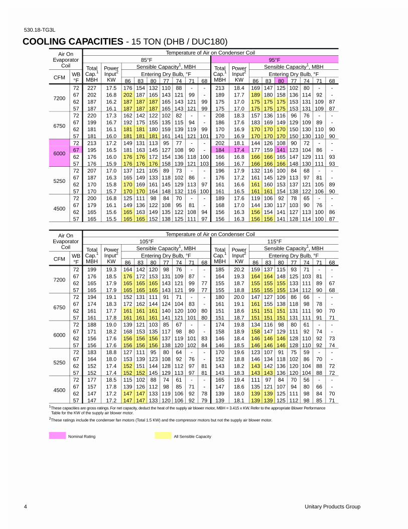
COOLING CAPACITIES - 15 TON (DHB / DUC180)
Air OnEvaporator
Coil
Temperature of Air on Condenser Coil105°F 115°F
TotalCap.1
MBH
PowerInput2
KW
Sensible Capacity1, MBH TotalCap.1
MBH
PowerInput2
KW
Sensible Capacity1, MBH
CFMWB°F
Entering Dry Bulb, °F Entering Dry Bulb, °F86 83 80 77 74 71 68 86 83 80 77 74 71 68
7200
72 199 19.3 164 142 120 98 76 - - 185 20.2 159 137 115 93 71 - -67 176 18.5 176 172 153 131 109 87 - 164 19.3 164 164 148 125 103 81 -62 165 17.9 165 165 165 143 121 99 77 155 18.7 155 155 155 133 111 89 6757 165 17.9 165 165 165 143 121 99 77 155 18.8 155 155 155 134 112 90 68
6750
72 194 19.1 152 131 111 91 71 - - 180 20.0 147 127 106 86 66 - -67 174 18.3 172 162 144 124 104 83 - 161 19.1 161 155 138 118 98 78 -62 161 17.7 161 161 161 140 120 100 80 151 18.6 151 151 151 131 111 90 7057 161 17.8 161 161 161 141 121 101 80 151 18.7 151 151 151 131 111 91 71
6000
72 188 19.0 139 121 103 85 67 - - 174 19.8 134 116 98 80 61 - -67 171 18.2 168 153 135 117 98 80 - 158 18.9 158 147 129 111 92 74 -62 156 17.6 156 156 156 137 119 101 83 146 18.4 146 146 146 128 110 92 7357 156 17.6 156 156 156 138 120 102 84 146 18.5 146 146 146 128 110 92 74
5250
72 183 18.8 127 111 95 80 64 - - 170 19.6 123 107 91 75 59 - -67 164 18.0 153 139 123 108 92 76 - 152 18.8 146 134 118 102 86 70 -62 152 17.4 152 151 144 128 112 97 81 143 18.2 143 142 136 120 104 88 7257 152 17.4 152 152 145 129 113 97 81 143 18.3 143 143 136 120 104 88 72
4500
72 177 18.5 115 102 88 74 61 - - 165 19.4 111 97 84 70 56 - -67 157 17.8 139 126 112 98 85 71 - 147 18.6 135 121 107 94 80 66 -62 147 17.2 147 147 133 119 106 92 78 139 18.0 139 139 125 111 98 84 7057 147 17.2 147 147 133 120 106 92 79 139 18.1 139 139 125 112 98 85 71
1These capacities are gross ratings. For net capacity, deduct the heat of the supply air blower motor, MBH = 3.415 x KW. Refer to the appropriate Blower Performance Table for the KW of the supply air blower motor.2These ratings include the condenser fan motors (Total 1.5 KW) and the compressor motors but not the supply air blower motor.
All Sensible Capacity
Air OnEvaporator
Coil
Temperature of Air on Condenser Coil85°F 95°F
TotalCap.1
MBH
PowerInput2
KW
Sensible Capacity1, MBH TotalCap.1
MBH
PowerInput2
KW
Sensible Capacity1, MBH
CFMWB°F
Entering Dry Bulb, °F Entering Dry Bulb, °F86 83 80 77 74 71 68 86 83 80 77 74 71 68
7200
72 227 17.5 176 154 132 110 88 - - 213 18.4 169 147 125 102 80 - -67 202 16.8 202 187 165 143 121 99 - 189 17.7 189 180 158 136 114 92 -62 187 16.2 187 187 187 165 143 121 99 175 17.0 175 175 175 153 131 109 8757 187 16.1 187 187 187 165 143 121 99 175 17.0 175 175 175 153 131 109 87
6750
72 220 17.3 162 142 122 102 82 - - 208 18.3 157 136 116 96 76 - -67 199 16.7 192 175 155 135 115 94 - 186 17.6 183 169 149 129 109 89 -62 181 16.1 181 181 180 159 139 119 99 170 16.9 170 170 170 150 130 110 9057 181 16.0 181 181 181 161 141 121 101 170 16.9 170 170 170 150 130 110 90
6000
72 213 17.2 149 131 113 95 77 - - 202 18.1 144 126 108 90 72 - -67 195 16.5 181 163 145 127 108 90 - 184 17.4 177 159 141 123 104 86 -62 176 16.0 176 176 172 154 136 118 100 166 16.8 166 166 165 147 129 111 9357 176 15.9 176 176 176 158 139 121 103 166 16.7 166 166 166 148 130 111 93
5250
72 207 17.0 137 121 105 89 73 - - 196 17.9 132 116 100 84 68 - -67 187 16.3 165 149 133 118 102 86 - 176 17.2 161 145 129 113 97 81 -62 170 15.8 170 169 161 145 129 113 97 161 16.6 161 160 153 137 121 105 8957 170 15.7 170 170 164 148 132 116 100 161 16.5 161 161 154 138 122 106 90
4500
72 200 16.8 125 111 98 84 70 - - 189 17.6 119 106 92 78 65 - -67 179 16.1 149 136 122 108 95 81 - 168 17.0 144 130 117 103 90 76 -62 165 15.6 165 163 149 135 122 108 94 156 16.3 156 154 141 127 113 100 8657 165 15.5 165 165 152 138 125 111 97 156 16.3 156 156 141 128 114 100 87
Nominal Rating
530.18-TG3L
4 Unitary Products Group

COOLING CAPACITIES - 20 TON (DHB / DUC240) Air On
EvaporatorCoil
Temperature of Air on Condenser Coil85°F 95°F
TotalCap.1
MBH
PowerInput2
KW
Sensible Capacity1, MBH TotalCap.1
MBH
PowerInput2
KW
Sensible Capacity1, MBH
CFMWB°F
Entering Dry Bulb, °F Entering Dry Bulb, °F86 83 80 77 74 71 68 86 83 80 77 74 71 68
9400
72 308 23.5 243 213 183 153 123 - - 290 25.2 235 205 175 145 116 - -67 270 22.5 270 254 225 195 165 135 - 259 23.8 259 246 216 186 156 126 -62 240 21.9 240 240 240 210 180 150 120 230 23.2 230 230 230 200 170 140 11057 240 21.3 240 240 240 210 180 150 120 230 22.6 230 230 230 200 170 140 110
9000
72 299 23.3 224 197 170 143 116 - - 282 24.9 216 189 162 135 108 - -67 266 22.3 258 238 211 184 158 131 - 254 23.6 247 229 202 175 148 121 -62 233 21.7 233 233 231 204 177 150 123 223 23.0 223 223 220 193 166 139 11257 233 21.2 233 233 233 207 180 153 126 223 22.4 223 223 223 196 169 142 116
8000
72 290 23.1 205 181 157 133 109 - - 273 24.6 196 172 148 125 101 - -67 262 22.1 246 222 198 174 150 127 - 250 23.3 235 211 188 164 140 116 -62 227 21.5 227 227 221 197 173 150 126 216 22.7 216 216 209 186 162 138 11457 227 21.0 227 227 227 203 179 155 131 216 22.1 216 216 216 193 169 145 121
7000
72 285 23.0 189 167 146 125 104 - - 267 24.4 182 160 139 118 97 - --67 254 22.0 224 203 182 161 140 119 - 241 23.1 216 195 174 153 132 110 -62 223 21.5 223 218 206 185 163 142 121 211 22.5 211 209 196 175 154 133 11257 223 20.9 223 220 211 190 169 148 126 211 21.9 211 211 203 182 161 139 118
6000
72 280 22.9 172 154 135 117 98 - - 260 24.2 167 148 130 111 93 - -67 246 21.9 203 185 166 148 129 111 - 232 22.9 197 179 160 142 123 105 -62 219 21.4 219 209 190 172 153 135 116 206 22.3 206 202 183 165 146 128 10957 219 20.8 219 214 195 177 158 140 121 206 21.7 206 206 189 171 152 134 115
Air OnEvaporator
Coil
Temperature of Air on Condenser Coil105°F 115°F
TotalCap.1
MBH
PowerInput2
KW
Sensible Capacity1, MBH TotalCap.1
MBH
PowerInput2
KW
Sensible Capacity1, MBH
CFMWB°F
Entering Dry Bulb, °F Entering Dry Bulb, °F86 83 80 77 74 71 68 86 83 80 77 74 71 68
9400
72 269 26.4 224 194 164 134 104 - - 248 27.6 213 183 153 123 93 - -67 241 24.9 241 234 206 176 146 116 - 222 26.0 222 222 195 165 135 105 -62 218 24.2 218 218 218 189 159 129 99 207 25.3 207 207 207 177 147 118 8857 218 23.6 218 218 218 189 159 129 99 207 24.7 207 207 207 177 147 118 88
9000
72 263 26.1 206 179 152 126 99 - - 243 27.3 197 170 143 116 89 - -67 237 24.7 234 219 193 166 139 112 - 221 25.8 221 210 184 157 130 103 -62 213 24.0 213 213 210 183 156 129 102 203 25.1 203 203 200 173 146 119 9257 213 23.4 213 213 213 186 159 132 106 203 24.5 203 203 203 176 149 122 95
8000
72 256 25.9 188 164 140 117 93 - - 238 27.1 180 156 132 109 85 - -67 234 24.5 227 204 180 156 133 109 - 219 25.6 219 197 173 149 125 102 -62 208 23.8 208 208 201 177 153 129 106 199 24.8 199 199 192 168 145 121 9757 208 23.2 208 208 208 184 160 136 112 199 24.3 199 199 199 175 151 127 103
7000
72 249 25.7 175 153 132 111 90 - - 232 27.1 168 146 125 104 83 - -67 226 24.3 210 189 168 147 125 104 - 210 25.6 203 183 162 141 119 98 -62 202 23.7 202 201 189 168 147 126 104 194 24.8 194 194 182 161 140 118 9757 202 23.1 202 202 195 174 153 132 111 194 24.2 194 194 188 167 146 124 103
6000
72 243 25.6 161 143 124 106 87 - - 226 27.0 155 137 118 100 81 - -67 217 24.2 192 174 155 137 118 100 - 202 25.5 187 169 150 132 113 95 -62 197 23.6 197 195 177 159 140 122 103 189 24.8 189 189 171 153 134 116 9757 197 23.0 197 197 183 165 146 128 109 189 24.2 189 189 177 159 140 122 103
1These capacities are gross ratings. For net capacity, deduct the heat of the supply air blower motor, MBH = 3.415 x KW. Refer to the appropriate Blower Performance Table for the KW of the supply air blower motor.2These ratings include the condenser fan motors (Total 2.3 KW) and the compressor motors but not the supply air blower motor.
All Sensible CapacityNominal Rating
530.18-TG3L
Unitary Products Group 5

BLOWER PERFORMANCE - (15 TON SUPPLY AIR)
DHB180 - BOTTOM DUCT CONNECTIONS
BLOWERSPEED,(RPM)
MOTORPULLEY(TURNSOPEN)*
CFM4500 5250 6000 6750 7200
ESP BHP KW ESP BHP KW ESP BHP KW ESP BHP KW ESP BHP KW
208 VOLT AND STANDARD DRIVE850 6.0** 0.9 2.4 2.2 0.7 3.0 2.7 0.5 3.2 2.9 - - - - - -870 5.5 1.0 2.5 2.3 0.8 3.1 2.8 0.6 3.5 3.1 0.2 4.1 3.7 - - -915 4.5 1.1 2.6 2.4 0.9 3.4 3.0 0.7 3.7 3.3 0.3 4.4 3.9 0.2 4.5 4.0965 3.5 1.2 2.9 2.6 1.0 3.6 3.2 0.8 4.0 3.6 0.5 4.7 4.2 0.4 4.9 4.4980 3.0 1.3 3.0 2.7 1.1 3.7 3.3 0.9 4.1 3.7 0.6 4.8 4.3 0.5 5.1 4.61010 2.0 1.4 3.1 2.8 1.2 3.8 3.4 1.0 4.2 3.8 0.7 5.0 4.5 0.6 5.4 4.81040 1.0 1.5 3.2 2.9 1.3 3.9 3.5 1.1 4.5 4.0 0.9 5.2 4.7 0.7 5.7 5.1
208 VOLT AND HIGH SPEED DRIVE ACCESSORY965 6.0 1.2 2.9 2.6 1.0 3.6 3.2 0.8 4.0 3.6 0.5 4.7 4.2 0.4 5.0 4.4980 5.5 1.3 3.0 2.7 1.1 3.7 3.3 0.9 4.1 3.7 0.6 4.8 4.3 0.5 5.1 4.61025 4.5 1.5 3.2 2.9 1.3 3.9 3.5 1.1 4.5 4.0 0.8 5.1 4.6 0.7 5.6 5.01065 3.5 1.6 3.4 3.0 1.4 4.0 3.6 1.2 4.7 4.2 1.0 5.5 4.9 - - -1095 3.0 1.7 3.5 3.1 1.5 4.2 3.8 1.3 4.9 4.4 1.2 5.7 5.1 - - -1130 2.0 1.9 3.7 3.3 1.7 4.5 4.0 1.5 5.1 4.6 - - - - - -1170 1.0 2.1 3.9 3.5 2.0 4.7 4.2 1.8 5.5 4.9 - - - - - -
230/460/575 VOLT AND STANDARD DRIVE870 6.0** 1.0 2.4 2.2 0.8 3.1 2.8 0.6 3.5 3.1 0.2 4.1 3.7 - - -915 5.0 1.1 2.6 2.4 0.9 3.3 3.0 0.7 3.7 3.3 0.3 4.4 3.9 0.2 4.5 4.0965 4.0 1.2 2.9 2.6 1.0 3.6 3.2 0.8 4.0 3.6 0.5 4.7 4.2 0.4 5.0 4.4980 3.5 1.3 3.0 2.7 1.1 3.7 3.3 0.9 4.1 3.7 0.6 4.8 4.3 0.5 5.1 4.61040 2.0 1.5 3.2 2.9 1.3 3.9 3.5 1.1 4.5 4.0 0.9 5.3 4.7 0.7 5.7 5.11065 1.0 1.6 3.3 3.0 1.4 4.0 3.6 1.2 4.7 4.2 1.0 5.5 4.9 - - -
230/460/575 VOLT AND HIGH SPEED DRIVE ACCESSORY980 6.0 1.3 2.9 2.6 1.1 3.7 3.3 0.9 4.1 3.7 0.6 4.8 4.3 0.5 5.1 4.61040 4.5 1.5 3.2 2.9 1.3 3.9 3.5 1.1 4.5 4.0 0.9 5.3 4.7 0.7 5.7 5.11065 4.0 1.6 3.4 3.0 1.4 4.0 3.6 1.2 4.7 4.2 1.0 5.5 4.9 - - -1095 3.5 1.7 3.5 3.1 1.5 4.2 3.8 1.3 4.9 4.4 1.2 5.7 5.1 - - -1130 2.5 1.9 3.7 3.3 1.7 4.5 4.0 1.5 5.1 4.6 - - - - - -1170 1.5 2.1 3.9 3.5 2.0 4.7 4.2 1.8 5.5 4.9 - - - - - -1190 1.0 2.2 4.0 3.6 2.1 4.8 4.3 2.0 5.7 5.1 - - - - - -
NOTES: 1. Blower performance includes fixed outdoor air, 2" T/A filters, a dry evaporator coil and no electric heat.
2. Refer to Page 10 for additional static resistances.
ESP = External Static Pressure available for the supply and return air duct system. All internal unit resistances have been deducted from the total static pressure of the blower.
* Do NOT close the pulley below 1 turn open.
** Factory setting.
530.18-TG3L
6 Unitary Products Group

BLOWER PERFORMANCE - (15 TON SUPPLY AIR)
DUC180 - BOTTOM DUCT CONNECTIONS
BLOWERSPEED,(RPM)
MOTORPULLEY(TURNSOPEN)*
CFM4500 5250 6000 6750 7200
ESP BHP KW ESP BHP KW ESP BHP KW ESP BHP KW ESP BHP KW
208 VOLT AND STANDARD DRIVE850 6.0** 0.9 2.4 2.1 0.6 2.9 2.6 0.3 3.4 3.0 - - - - - -870 5.5 1.0 2.5 2.2 0.7 3.0 2.7 0.4 3.5 3.1 - - - - - -915 4.5 1.1 2.6 2.4 0.8 3.1 2.8 0.5 3.6 3.2 0.2 4.1 3.7 - - -965 3.5 1.2 2.7 2.5 0.9 3.2 2.9 0.6 3.7 3.3 0.4 4.4 3.9 0.2 5.0 4.5980 3.0 1.3 2.9 2.6 1.0 3.4 3.0 0.7 3.8 3.4 0.5 4.5 4.0 0.3 5.1 4.61010 2.0 1.4 3.0 2.7 1.1 3.6 3.2 0.8 4.0 3.6 0.6 4.7 4.2 0.4 5.4 4.81040 1.0 1.6 3.2 2.9 1.3 3.8 3.4 1.0 4.4 3.9 0.8 5.0 4.5 0.6 5.6 5.0
208 VOLT AND HIGH SPEED DRIVE ACCESSORY965 6.0 1.2 2.7 2.5 0.9 3.2 2.9 0.6 3.7 3.3 0.4 4.4 3.9 0.2 5.0 4.5980 5.5 1.3 2.9 2.6 1.0 3.4 3.0 0.7 3.8 3.4 0.5 4.5 4.0 0.3 5.1 4.61025 4.5 1.4 3.1 2.8 1.2 3.6 3.2 0.9 4.1 3.7 0.7 4.8 4.3 0.4 5.5 4.91065 3.5 1.6 3.4 3.0 1.4 3.9 3.5 1.1 4.5 4.0 0.9 5.1 4.6 - - -1125 2.0 1.9 3.6 3.2 1.7 4.4 3.9 1.4 5.0 4.5 1.2 5.8 5.2 - - -1170 1.0 2.1 3.9 3.5 1.9 4.7 4.2 1.6 5.5 4.9 - - - - - -
230/460/575 VOLT AND STANDARD DRIVE870 6.0** 1.0 2.5 2.2 0.7 3.0 2.7 0.4 3.5 3.1 - - - - - -915 5.0 1.1 2.6 2.4 0.8 3.1 2.8 0.5 3.6 3.2 0.2 4.1 3.7 - - -965 4.0 1.2 2.7 2.5 0.9 3.2 2.9 0.6 3.7 3.3 0.4 4.4 3.9 0.2 5.0 4.5980 3.5 1.3 2.9 2.6 1.0 3.4 3.0 0.7 3.8 3.4 0.5 4.5 4.0 0.3 5.1 4.61015 2.5 1.4 3.0 2.7 1.1 3.6 3.2 0.8 4.0 3.6 0.6 4.7 4.2 0.4 5.4 4.81050 1.5 1.5 3.1 2.8 1.2 3.7 3.3 0.9 4.2 3.8 0.7 4.9 4.4 0.5 5.7 5.11065 1.0 1.6 3.4 3.0 1.4 3.9 3.5 1.1 4.5 4.0 0.9 5.1 4.6 - - -
230/460/575 VOLT AND HIGH SPEED DRIVE ACCESSORY980 6.0 1.3 2.9 2.6 1.0 3.4 3.0 0.7 3.8 3.4 0.5 4.5 4.0 0.3 5.1 4.61045 4.5 1.6 3.2 2.9 1.3 3.8 3.4 1.0 4.4 3.9 0.8 5.0 4.5 0.6 5.6 5.01065 4.0 1.7 3.4 3.0 1.4 3.9 3.5 1.1 4.5 4.0 0.9 5.1 4.6 - - -1125 2.5 1.9 3.6 3.2 1.7 4.4 3.9 1.4 5.0 4.5 1.2 5.8 5.2 - - -1170 1.5 2.1 3.9 3.5 1.8 4.7 4.2 1.6 5.5 4.9 - - - - - -1190 1.0 2.2 4.0 3.6 1.9 4.8 4.3 1.7 5.6 5.0 - - - - - -
NOTES: 1. Blower performance includes a gas-fired heat exchanger, fixed outdoor air, 2" T/A filters and a dry evaporator coil.
2. Refer to Page 10 for additional static resistances.
ESP = External Static Pressure available for the supply and return air duct system. All internal unit resistances have been deducted from the total static pressure of the blower.
* Do NOT close the pulley below 1 turn open.
** Factory setting.
530.18-TG3L
Unitary Products Group 7

BLOWERSPEED,(RPM)
MOTORPULLEY(TURNSOPEN)*
CFM6000 7000 8000 9000 9400
ESP BHP KW ESP BHP KW ESP BHP KW ESP BHP KW ESP BHP KW
208 VOLT AND STANDARD DRIVE870 6.0** 0.4 2.1 1.8 0.1 2.3 2.0 - - - - - - - - -900 5.0 0.8 3.2 2.7 0.5 3.5 2.9 0.2 3.8 3.2 - - - - - -930 4.0 1.1 4.1 3.4 0.9 4.5 3.8 0.6 4.9 4.1 0.1 5.1 4.3 - - -950 3.0 1.3 4.6 3.9 1.1 5.1 4.3 0.8 5.5 4.6 0.4 5.9 5.0 - - -980 2.0 1.6 5.3 4.5 1.4 5.8 4.9 1.2 6.3 5.3 0.7 6.9 5.8 0.2 7.3 6.1
1015 1.0 1.9 5.9 5.0 1.7 6.5 5.5 1.5 7.0 5.9 1.0 7.7 6.5 0.6 8.2 6.9
208 VOLT AND HIGH SPEED DRIVE ACCESSORY950 6.0 1.3 4.6 3.9 1.1 5.1 4.3 0.8 5.5 4.6 0.4 5.9 5.0 - - -980 5.0 1.6 5.3 4.5 1.4 5.8 4.9 1.2 6.3 5.3 0.7 6.9 5.8 0.2 7.3 6.1
1010 4.0 1.8 5.8 4.9 1.7 6.3 5.3 1.5 6.9 5.8 1.0 7.5 6.3 0.5 7.9 6.71020 3.5 1.9 6.1 5.1 1.8 6.5 5.5 1.6 7.1 6.0 1.1 7.8 6.6 0.6 8.3 7.01035 3.0 2.0 6.2 5.2 1.9 6.8 5.7 1.7 7.4 6.2 1.2 8.1 6.8 0.7 8.6 7.31050 2.5 2.1 6.4 5.4 2.0 7.0 5.9 1.8 7.6 6.4 1.3 8.3 7.0 - - -1075 2.0 2.3 6.6 5.5 2.1 7.2 6.0 1.9 7.8 6.6 1.5 8.6 7.2 - - -1100 1.0 2.4 6.7 5.6 2.2 7.3 6.1 2.1 7.9 6.7 - - - - - -
230/460/575 VOLT AND STANDARD DRIVE870 6.0** 0.4 2.1 1.8 0.1 2.3 2.0 - - - - - - - - -900 5.0 0.8 3.2 2.7 0.5 3.5 2.9 0.2 3.8 3.2 - - - - - -930 4.0 1.1 4.1 3.4 0.9 4.5 3.8 0.6 4.9 4.1 0.1 5.1 4.3 - - -950 3.5 1.3 4.6 3.9 1.1 5.1 4.3 0.8 5.5 4.6 0.4 5.9 5.0 - - -980 2.5 1.6 5.3 4.5 1.4 5.8 4.9 1.2 6.3 5.3 0.7 6.9 5.8 0.2 7.3 6.1
1015 1.5 1.9 5.9 5.0 1.7 6.5 5.5 1.5 7.0 5.9 1.0 7.7 6.5 0.6 8.2 6.91025 1.0 2.0 6.1 5.1 1.8 6.6 5.6 1.6 7.3 6.1 1.1 7.9 6.7 0.7 8.6 7.3
230/460/575 VOLT AND HIGH SPEED DRIVE ACCESSORY950 6.0 1.3 4.6 3.9 1.1 5.1 4.3 0.8 5.5 4.6 0.4 5.9 5.0 - - -980 5.0 1.6 5.3 4.5 1.4 5.8 4.9 1.2 6.3 5.3 0.7 6.9 5.8 0.2 7.3 6.1
1015 4.0 1.9 5.9 5.0 1.7 6.5 5.5 1.5 7.0 5.9 1.0 7.7 6.5 0.6 8.2 6.91035 3.5 2.0 6.2 5.2 1.9 6.8 5.7 1.7 7.4 6.2 1.2 8.1 6.8 0.7 8.6 7.31050 3.0 2.1 6.4 5.4 2.0 7.0 5.9 1.8 7.6 6.4 1.3 8.3 7.0 - - -1080 2.0 2.3 6.6 5.5 2.1 7.2 6.0 1.9 7.8 6.6 1.5 8.6 7.2 - - -1100 1.5 2.4 6.7 5.6 2.2 7.3 6.1 2.1 7.9 6.7 - - - - - -1120 1.0 2.5 6.8 5.7 2.3 7.4 6.2 2.2 8.1 6.8 - - - - - -
NOTES: 1. Blower performance includes fixed outdoor air, 2" T/A filters, a dry evaporator coil and no electric heat.
2. Refer to Page 10 for additional static resistances.
ESP = External Static Pressure available for the supply and return air duct system. All internal unit resistances have been deducted from the total static pressure of the blower.
* Do NOT close the pulley below 1 turn open.
** Factory setting.
BLOWER PERFORMANCE - (20 TON SUPPLY AIR)
DHB240 - BOTTOM DUCT CONNECTIONS
530.18-TG3L
8 Unitary Products Group

BLOWERSPEED,(RPM)
MOTORPULLEY(TURNSOPEN)*
CFM6000 7000 8000 9000 9400
ESP BHP KW ESP BHP KW ESP BHP KW ESP BHP KW ESP BHP KW
208 VOLT AND STANDARD DRIVE870 6.0** 1.3 3.6 3.0 0.7 4.3 3.7 0.2 5.1 4.3 - - - - - -900 5.0 1.4 3.8 3.2 0.9 4.7 4.0 0.4 5.6 4.7 - - - - - -930 4.0 1.6 4.1 3.4 1.1 5.0 4.2 0.6 5.9 5.0 0.1 6.7 5.7 - - -950 3.0 1.7 4.2 3.6 1.3 5.1 4.3 0.8 6.0 5.1 0.2 6.9 5.8 - - -980 2.0 1.9 4.5 3.8 1.5 5.4 4.5 1.0 6.3 5.3 0.4 7.2 6.1 0.1 8.5 7.1995 1.5 2.1 4.6 3.9 1.6 5.5 4.7 1.1 6.4 5.4 0.5 7.5 6.3 0.2 8.6 7.3
1015 1.0 2.2 4.8 4.0 1.7 5.7 4.8 1.2 6.6 5.6 0.7 7.8 6.6 - - -
208 VOLT AND HIGH SPEED DRIVE ACCESSORY950 6.0 1.7 4.2 3.6 1.3 5.1 4.3 0.8 6.0 5.1 0.2 6.9 5.8 - - -980 5.0 1.9 4.5 3.8 1.5 5.4 4.5 1.0 6.3 5.3 0.4 7.2 6.1 0.1 8.5 7.1995 4.5 2.1 4.6 3.9 1.6 5.5 4.7 1.1 6.4 5.4 0.5 7.5 6.3 0.2 8.6 7.3
1025 3.5 2.3 4.9 4.1 1.8 5.8 4.9 1.3 6.7 5.7 0.7 8.0 6.7 - - -1050 2.5 2.5 5.1 4.3 2.0 6.1 5.1 1.4 7.1 6.0 0.9 8.4 7.0 - - -1065 2.0 2.6 5.3 4.4 2.1 6.3 5.3 1.5 7.3 6.2 1.0 8.6 7.2 - - -1100 1.0 2.9 5.6 4.7 2.3 6.8 5.7 1.8 7.9 6.6 - - - - - -
230/460/575 VOLT AND STANDARD DRIVE870 6.0** 1.3 3.6 3.0 0.7 4.3 3.7 0.2 5.1 4.3 - - - - - -900 5.0 1.4 3.8 3.2 0.9 4.7 4.0 0.4 5.6 4.7 - - - - - -930 4.0 1.6 4.1 3.4 1.1 5.0 4.2 0.6 5.9 5.0 0.1 6.7 5.7 - - -950 3.5 1.7 4.2 3.6 1.3 5.1 4.3 0.8 6.0 5.1 0.2 6.9 5.8 - - -965 2.5 1.9 4.5 3.8 1.5 5.4 4.5 1.0 6.3 5.3 0.4 7.2 6.1 0.1 8.5 7.1995 2.0 2.1 4.6 3.9 1.6 5.5 4.7 1.1 6.4 5.4 0.5 7.5 6.3 0.2 8.6 7.3
1015 1.5 2.2 4.8 4.0 1.7 5.7 4.8 1.2 6.6 5.6 0.6 7.8 6.6 - - -1025 1.0 2.3 4.9 4.1 1.8 5.8 4.9 1.3 6.7 5.7 0.7 8.0 6.7 - - -
230/460/575 VOLT AND HIGH SPEED DRIVE ACCESSORY950 6.0 1.7 4.2 3.6 1.3 5.1 4.3 0.8 6.0 5.1 0.2 6.9 5.8 - - -980 5.0 1.9 4.5 3.8 1.5 5.4 4.5 1.0 6.3 5.3 0.4 7.2 6.1 0.1 8.5 7.1995 4.5 2.1 4.6 3.9 1.6 5.5 4.7 1.1 6.4 5.4 0.5 7.5 6.3 0.2 8.6 7.3
1015 4.0 2.2 4.8 4.0 1.7 5.7 4.8 1.2 6.6 5.6 0.6 7.8 6.6 - - -1025 3.5 2.3 4.9 4.1 1.8 5.8 4.9 1.3 6.7 5.7 0.7 8.0 6.7 - - -1050 3.0 2.5 5.1 4.3 2.0 6.1 5.1 1.4 7.1 6.0 0.9 8.4 7.0 - - -1065 2.5 2.6 5.3 4.4 2.1 6.3 5.3 1.5 7.3 6.2 1.0 8.6 7.2 - - -1100 1.5 2.9 5.6 4.7 2.3 6.8 5.7 1.8 7.9 6.6 - - - - - -1120 1.0 3.1 5.8 4.9 2.5 7.0 5.9 1.9 8.3 6.9 - - - - - -
NOTES: 1. Blower performance includes a gas-fired heat exchanger, fixed outdoor air, 2" T/A filters and a dry evaporator coil.
2. Refer to Page 10 for additional static resistances.
ESP = External Static Pressure available for the supply and return air duct system. All internal unit resistances have been deducted from the total static pressure of the blower.
* Do NOT close the pulley below 1 turn open.
** Factory setting.
BLOWER PERFORMANCE - (20 TON SUPPLY AIR)
DUC240 - BOTTOM DUCT CONNECTIONS
530.18-TG3L
Unitary Products Group 9

POWER EXHAUST PERFORMANCE
MOTORSPEED
STATIC RESISTANCE OF RETURN DUCTWORK, IWG0.2 0.3 0.4 0.5 0.6
CFM KW CFM KW CFM KW CFM KW CFM KW
HIGH* 5250 0.83 4500 0.85 4200 0.88 3750 0.93 3000 0.99
MEDIUM 4900 0.77 3900 0.79 3500 0.82 2900 0.85 - -
LOW 4400 0.72 3700 0.74 3000 0.78 - - - -
*Factory Setting Power Exhaust motor is a 3/4 HP, PSC type with sleeve bearings, a 48 frame and inherent protection.
BLOWER MOTOR AND DRIVE DATA
MODELSIZE DRIVE
BLOWERRANGE(RPM)
MOTOR1 ADJUSTABLE MOTOR PULLEY FIXED BLOWER PULLEY BELT(NOTCHED)
HP FRAME EFF.(%)
DESIG-NATION
OUTSIDEDIA.(IN.)
PITCHDIA.(IN.)
BORE(IN.)
DESIG-NATION
OUTSIDEDIA.(IN.)
PITCHDIA.(IN.)
BORE(IN.)
DESIG-NATION
PITCHLENGTH
(IN.)QTY.
15 TON
Stan-dard 850/1065
5 184T 83 1VP56 5.35 4.3-5.32 1-1/8
BK90 8.75 8.4 1 BX70 71.8 1
HighSpeedAccess
965/1190 BK80 7.75 7.4 1 BX68 69.8 1
20 TON
Stan-dard 870/1025
7.5 213T 89 1VP68 6.75 5.5-6.52 1-3/8
BK120 11.75 11.4 1-3/16 BX83 84.8 1
HighSpeedAccess
950/1120 BK110 10.75 10.4 1-3/16 BX80 81.8 1
1All motors have a nominal speed of 1800 RPM, a 1.15 service factor and a solid base. They can operate to the limit of their service factor because they are located in the moving air, upstream of any heating device.2 Do NOT close this pulley below 1 turn open.
STATIC RESISTANCES*
EXTERNAL STATIC PRESSURE DROP
DESCRIPTION
RESISTANCE, IWGCFM
15 TON 20 TON4500 6000 7200 6000 8000 9400
WET COIL 0.1 0.1 0.1 0.1 0.1 0.1
ELECTRIC HEAT OPTIONS
18 KW 0.1 0.1 0.1 0.1 0.1 0.136 KW 0.1 0.2 0.3 0.1 0.2 0.354 KW 0.2 0.3 0.4 0.2 0.3 0.472 KW 0.2 0.4 0.6 0.2 0.4 0.6
ECONOMIZER OPTION 0.1 0.1 0.1 0.1 0.1 0.1HORIZONTAL DUCT CONNECTIONS 0.2 0.3 0.5 0.2 0.3 0.5
*Deduct these resistance values from the available unit ESP values listed in the respective blower performance table except for Horizontal Duct Connections (Shaded ). Add these values due to less airflow resistance.
530.18-TG3L
10 Unitary Products Group
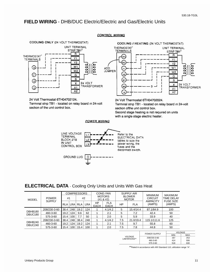
MODEL POWERSUPPLY
COMPRESSORS COND. FANMOTORS(#1 & #2)
SUPPLY AIRBLOWERMOTOR
MINIMUMCIRCUIT
AMPACITY(AMPS)
MAXIMUMTIME DELAYFUSE SIZE
(AMPS)
#1 #2
RLA LRA RLA LRA HPEACH
FLAEACH HP FLA
DBHB180DBUC180
208/230-3-60 38.4 248 19.2 124 1 4.1/4.2 5 15.4/14.4 87.1/84.9 100460-3-60 19.2 124 9.6 62 1 2.1 5 7.2 42.4 50575-3-60 15.4 100 7.7 50 1 2.0 5 5.9 33.9 40
DBHB240DBUC240
208/230-3-60 38.4 248 38.4 248 1 4.1/4.2 7.5 21.0/19.4 115.1/111.6 125460-3-60 19.2 124 19.2 124 1 2.1 7.5 9.7 55.8 60575-3-60 15.4 100 15.4 100 1 2.0 7.5 7.8 44.8 50
ELECTRICAL DATA - Cooling Only Units and Units With Gas Heat
FIELD WIRING - DHB/DUC Electric/Electric and Gas/Electric Units
VOLTAGELIMITATIONS**
POWER SUPPLYVOLTAGE
MIN. MAX.208/230-3-60 187 253
460-3-60 414 506575-3-60 518 630
**Rated in accordance with ARI Standard 110, utilization range "A".
530.18-TG3L
Unitary Products Group 11

MODELSDHB/DUC
180 240EVAPORATOR
BLOWERCENTRIFUGAL BLOWER (Dia. x Wd. in.) 15 x 15 18 x 15FAN MOTOR HP 5 7.5
EVAPORATORCOIL
ROWS DEEP 3 3FINS PER INCH 13.5 13.5FACE AREA (Sq. Ft.) 15.5 20.5
CONDENSERFAN
(Two Per Unit)
PROPELLER DIA. (in.) (Each) 30 30FAN MOTOR HP (Each) 1 1NOM. CFM TOTAL (Each) 6500 7200
CONDENSERCOIL
ROWS DEEP 2 2FINS PER INCH 13 20FACE AREA (Sq. Ft.) 36.0 43.3
COMPRESSOR(Qty. Per Unit)
10-TON TANDEM 1* 25-TON HERMETIC 1 -
AIRFILTERS
QUANTITY PER UNIT (16" X 20" X 2") - 4QUANTITY PER UNIT (16" X 25" X 2") - 4QUANTITY PER UNIT (18" X 24" X 2") 5 -TOTAL FACE AREA (sq. ft.) 15.0 20.0
CHARGE REFRIGERANT 22(lbs./oz.)
SYSTEM NO. 1 17/8 18/0SYSTEM NO. 2 8/8 18/0
*This compressor will be energized first.
PHYSICAL DATABASIC UNITS
MODELDBHB
POWERSUPPLY
HEATER OPTION MINIMUMCIRCUIT
AMPACITY(AMPS)
MAXIMUMTIME DELAYFUSE SIZE
(AMPS)MODEL KW1 STAGES AMPS
-T180A
208-3-60
E018E036E054E072
13.527.040.654.1
1222
37.575.1
112.6150.1
87.1114.7161.6171.0
100125175200
230-3-60
E018E036E054E072
18.036.054.072.0
1222
43.386.6
129.9173.2
84.9127.3148.9192.2
100150175225
-W180A 460-3-60
E018E036E054E072
18.036.054.072.0
1222
21.743.365.086.6
42.463.674.596.1
507090110
-X180A 575-3-60
E018E036E054E072
18.036.054.072.0
1222
17.334.652.069.3
33.950.959.676.9
40607090
-T240A
208-3-60
E018E036E054E072
13.527.040.654.1
1222
37.575.1
112.6150.1
115.1124.1171.0180.4
125125175200
230-3-60
E018E036E054E072
18.036.054.072.0
1222
43.386.6
129.9173.2
111.6135.8157.4200.7
125150175225
-W240A 460-3-60
E018E036E054E072
18.036.054.072.0
1222
21.743.365.086.6
55.867.978.7100.4
607090110
-X240A 575-3-60
E018E036E054E072
18.036.054.072.0
1222
17.334.652.069.3
44.854.663.280.5
50607090
1Electric Heat CORRECTION FACTORS:
ELECTRICAL DATA - Units With Electric Heat
MODEL SIZE 180 240
Basic UnitDHB (Cooling only) 1900 2100DUC(Gas / Electric)
N300 2100 2300N400 2140 2340
Options
Economizer 160Economizer withPower Exhaust 245
Motorized Damper 150
Electric Heater(DHB only)
18 KW 2536 KW 3054 KW 3572 KW 40
AccessoriesRoof Curb 175 185Barometric Damper 45 45Wood Skid 200 220
NOMINAL VOLTAGE VOLTAGE KW CAP. MULTIPLIER208 208 1.00240 230 0.92480 460 0.92600 575 0.92
OPERATING WEIGHTS (LBS.)
530.18-TG3L
12 Unitary Products Group

All dimensions are in inches. They aresubject to change without notice. Certifieddimensions will be provided upon request.
CLEARANCESFront 36"
Back 24" (Less Economizer)49" (With Economizer)
Left Side (Filter Access) 24" (Less Economizer)36" (With Economizer)
Right Side (Cond. Coil) 36"Below Unit1 20"
Above Unit272" With 36" Maximum Horizontal Overhang (For Condenser Air Discharge)
1Units (applicable in U.S.A. only) may be installed on combustible floors made from wood or class A, B or C roof covering material.2Units must be installed oudoors. Overhanging structures or shrubs should not obstruct condenser air discharge outlet.
NOTE:DHB Models: Units and ductwork are approved for zero clearance to combustible materials when equipped with electric heaters.
DUC Models: A 1" clearance must be provided between any combustiblematerial and the supply air ductwork for a distance of 3 feet from the unit.
The products of combustion must not be allowed to accumulate within aconfined space and recirculate.
Locate unit so that the vent air outlet hood is at least:
• Three (3) feet above any forced air inlet located within 10 horizontal fe(excluding those integral to the unit).
• Four (4) feet below, 4 horizontal feet from, or 1 foot above any door or graviair inlet into the building.
• Four (4) feet from electric meters, gas meters, regulators and relief equipmen
HOLEOPENING
SIZE(DIA.)
USED FOR
A1-1/8" KO Control
WiringFront
3/4" NPS (Fem.) Bottom
B3-5/8" KO Power
WiringFront
3" NPS (Fem.) BottomC* 2-3/8" KO Gas Piping (Front)
D 1-11/16" Hole Gas Piping (Bottom)**
*1" NPT Required **Opening in the bottom of the unit can be located by the slice in the insulation.
UTILITIES ENTRY DATA
UNIT DIMENSIONS-(DHB AND DUC - 15 & 20 TON)
RETURN AIR
SUPPLYAIR
BOTTOM SUPPLYAND RETURN
AIR OPENINGS(See Note)
(B)POWER WIRINGENTRY
(A)CONTROL WIRING ENTRYNOTE:
For curb mounted units, refer to the curb hangerdimensions of the curb for the proper size of thesupply and return air duct connections.
UNIT BASE WITH RAILSShown separately to illustrateBottom Duct openings and PowerConnection locations
12-1/2"
9-1/4"
8-1/8"
9-3/4"
3-3/4"
(B)POWER WIRINGENTRY
(A)CONTROL WIRING ENTRY
92"
CONDENSERCOILS
OPTIONAL COILGUARD KIT
48-5/8" (15 TON)52-5/8" (20 TON)
COMPRESSORACCESS(See detail "X")
ECONOMIZER / MOTORIZED DAMPER,FIXED OUTDOOR INTAKE AIR ANDPOWER EXHAUST RAIN HOODS(See detail "Y")
FIELD-SUPPLIEDDISCONNECT SWITCHLOCATION
BLOWERACCESS
BLOWER MOTORACCESS
BLOWERCOMPARTMENTACCESS(Auxiliary)
DOT PLUG(For pressureDrop Reading)
FRONTVIEW ELECTRIC HEAT
ACCESS
CONTROL BOXACCESS
125-1/4" (15 TON)136-1/4" (20 TON)
21"
5"
9-3/4"
11-1/2"
2-3/4" 21-1/2"
33"
35"
5-7/8"
24-1/4" (15 TON)35-1/4" (20 TON)
RETURN AIR
SUPPLY AIR
OUTDOOR AIR
OUTDOOR AIR(Economizer)
DHBUNIT
� � � � � � �� � �
� � �� � �
� � � � � � � � �� � � � � � � � � �� � � � � � � � � �
� � � � � � � � �
� � � � � � � � � � � � �� � � � �
� � �� � � � � � � � � � � � � � �� � � � �
� � � � �� � � � � � � � � � � � � � ! � � " � # $ � � � % � � � � � � � & � � � � � � � & ' ( � �! " � � # " � # � � % � � & � � � � � � � % � � � � & � � ) � � ) � � � # " * � � � % � � & �# � ) ) + , � ' ! � � � � � � � ' " � � ! � � � � � � � � � " � # -
� � � � � � � � � � � . � � � � �
& � / � # � ) ' � ' � � + , � � � � " + + � # � � ' � � � � � � � � � � � � � � ) � " ( # $ � � / � �' ! � � ' # � " ) " ( � � � � � � " � �+ � � ' � " � #
0 1 2 0 3 1 4
5 2 0 3 6 4
7 2 0 3 7 4
5 2 8 3 6 4
8 2 8 3 6 4
� � � � � � � � � � � � �� � � � �
� � �� � � � � � � � � � � � � � �� � � � �
� � � � � � � �� � � �
� � � � � � � � � � � �� � � � � � 9 � �
� � � � � � �� � � � � � � � ! � � ' " + � 4 : 4 �
� � � � � � � ; � � � 3 � � � � � � � ; � � � � � � � � $� � : � � � � � � � � � � � � � � � 9 � � � � � � � � � � � � � � � : . � � � � � � � � � . � � � � � � � ! � � ' " + � 4 � 4 �
� � � � � 2 � � � � �� � � � � � � � � � � � � � .� � � � � � � �
� � � � �� � � �
� � � � � � � � � � �� � � �
� � � � �� � � � � � � � � �� � � � � � � < " + " ' � , �
� � � � � � �� � � � � ) � � # # � � �� � � ) � � � ' ! " ( �
� � � � �� � �
� � � � � � � � � :� � � �
1 0 4
= 4
5 2 8 3 6 4
0 0 2 0 3 1 4
1 2 8 3 6 4 1 0 2 0 3 1 4
8 8 4
8 = 4
= 2 > 3 7 4
6 ? 2 = 3 7 4
> 2 0 3 7 4
? 2 8 3 7 4
@ � � � � � � �� � � � � �. � � �
� � � � � � � �� � � � � � � � �. � � �
� � � . � � �� � � �
� � �� � � � � � �� � � � �
6 ? 2 = 3 7 4
0 0 2 0 3 7 4
� � �� � � � � �� � � � �
8 = 2 0 3 6 �
0 8 ? 2 0 3 6
= 1 2 = 3 7 �
� � � � � � � � �
� � � � � � � �
� � � � � � � � � �
� � � � � � � � � �� � � � � � � � � � � �
5 1 4
DUCUNIT
530.18-TG3L
Unitary Products Group 13

OUTDOOR AIR PANEL SIZES
15 TON UNITS 21-1/2" X 43"
20 TON UNITS 32-1/2" X 43"
CENTER OF GRAVITY
UNIT DIMENSIONS - CONT’D.-(DHB and DUC - 15 & 20 TON)
� � � � � �� � �
� � � � � � �� � �
� � �� � �
� � � � � � � � � �� � � �
� � � � � � �� � � �
� � � � � � �� � � �
� � � � � � � � � � � � � � �
� � � � � � � � � �� � � �
� � � � � � � � � � �� � � � � � � � � �� � � �
0 4 � � � � � � � � � �� � � � - � � � � � �� � � � � � � � � �
� � � � � �� � � �
� � � � � � �� � � � � ) � � # # � � �! � � ) � � � ' ! " ( �
� @ � � � � � � � � � � � � �
6 A 2 0 3 1 4
1 7 2 = 3 7 4 � � 0 = � � � # �8 5 2 = 3 7 4 � � 1 A � � � # �
1 > 2 8 3 6 4
= 2 0 3 7 4
0 7 2 = 3 7 4
= 2 0 3 1 4
6 A 2 8 3 7 4
� � � �@ � � �
DETAIL “X”ACCESSORY SIDE SUPPLY AND RETURN AIR OPENINGS
DUCT COVERS - Units are shipped with the bottomduct openings covered. An accessory flange kit is avail-able for connecting side ducts.For bottom duct applications:1. Remove the side panels from the supply and return air compartments to gain access to the bottom supply and return air duct covers.2. Remove and discard the bottom duct covers. (Duct openings are closed with sheet metal covers except when the unit includes a power exhaust option. The covering consists of a heavy black paper composition.)3. Replace the side supply and return air compartment panels.For side duct applications;1. Replace the side panels on the supply and return air compartments with the accessory flange kit panels.2. Connect ductwork to the duct flanges on the rear of the unit.
� � � � � � �� � � � � � � � � �
� � � � � � : . � � �� � � � � . � � �� � � � � � � � � � " � � � � � ) ' � � � � � �
� � � � � � � ; � �� � � � � � ; � �� � � � �� � � � � . � � �� � � � � � ! � � � � � " � � � � � ) ' � � � � � �
� � � � � � � ; � � � 3 � � � � � � � ; � � � � � � � �� � � � � � � � � � : . � � � � � � � � � . � � �
� � : � �� � � � � � � � � � �� � � � 9 � � . � � �� + � � ' � � ! � � � � � � � � � " �� � � ) ' � � � � � �
0 4 � � � � � � � � � � �� � � � �� � � # � � � � � � � ' ) ) � ! �
� � � � � @ � � � � . � � @ � � �� � � � � � � 4 � 4
� � � � � � � � . � � � � � � . � � �
8 ? 4
? ? 2 0 3 1 45 1 48 ? 2 0 3 6 4
= 4
8 6 2 0 3 6 4
0 ? 2 0 3 7 4
1 4
530.18-TG3L
14 Unitary Products Group

CENTER OF GRAVITY
�
�
�
�
����
4 POINT LOADS
UNIT4 - POINT LOADS (LBS)
TOTAL A B C D180 2060 483 525 548 504240 2260 568 814 888 620
UNIT4 - POINT LOADS (LBS)
TOTAL A B C D180 2300 539 563 612 586240 2500 538 563 715 684
NOTE: These weights are with economizer (electric heat) high heat, and the largest blower motor available (gas heat).
UNIT6 - POINT LOADS (LBS)
TOTAL A B C D E F180 2060 322 336 350 365 351 336240 2260 325 368 412 431 385 339
UNIT6 - POINT LOADS (LBS)
TOTAL A B C D E F180 2300 351 367 392 416 399 375240 2500 334 350 426 502 481 407
NOTE: These weights are with economizer (electric heat) high heat, and the largest blower motor available (gas heat).
�
�
�
�
�
�
����
6 POINT LOADS
CENTER OF GRAVITY
530.18-TG3L
Unitary Products Group 15

UNIT AND CURB APPLICATION
ROOF CURB DIMENSIONS-(DHB and DUC - 15 & 20 TON)
ROOF CURB BENEFITS
5/16"5/16"
➀ The 2" space between the ducts allows for “jumping” an existing roof joist.
➁ The 58-1/2" overall dimension of the ducts allows ductwork penetration between roof joists that are spaced on 72" centers.
NOTE: Ducts can be installed onto the curb from the roof. All electrical and gas line connections can be made inside the curb.
BASE RAIL3.56"
3.69"
530.18-TG3L
16 Unitary Products Group
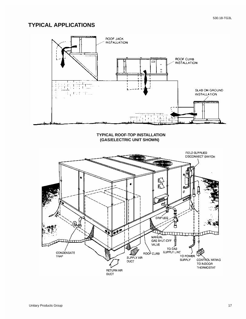
TYPICAL APPLICATIONS
TYPICAL ROOF-TOP INSTALLATION (GAS/ELECTRIC UNIT SHOWN)
530.18-TG3L
Unitary Products Group 17

530.18-TG3L
18 Unitary Products Group
530.18-TG3L
Unitary Products Group 19

Subject to change without notice. Printed in U.S.A.Copyright by Unitary Products Group 1995. All rights reserved. 530.18-TG3L (500)Code: EBL
Supersedes: 530.18-TG3L (793)Unitary 5005 Interstate NormanProducts Drive OklahomaGroup North 73069