Embed Size (px)
Citation preview

Design & Analysis of Diffuser Section of Four
Wheeler
Mr. M. Viswanath 1
, Mr. S. Sri Gowtham Raj Kumar 2
, Mr. K. Thamarai Mohan 3
, Mr. J. Yaseef 4.
1-Assistant Professor, 2,3&4-Students.
Department of Mechanical Engineering, Hindusthan Institute of Technology,
Othakkalmandapam, Coimbatore-641008, Tamilnadu, India
Abstract:- The aim of the paper is to examine the
aerodynamic behaviour and performance of the
diffuser. A diffuser in an automotive context is a
shaped section of the car underbody which
improves the cars aerodynamics properties by
enhancing the transistion between the high velocity
airflow underneath the car and the much slower
freestream airflow of the ambient
atmosphere. A two-dimensional analysis is
to provide an understanding of the relation between
diffuser height and associated diffuser angle for
maximum downforce. Based upon the observations
from the analysis the diffuser is designed with the
efficient diffuser angle which produces maximum
downforce.
INTRODUCTION:
In earlier years study of aerodynamics had
primarily been on the upper surface of the car,
this provided a certain improvement but was not
able to completely minimize the drag. Thus study
of underbody aerodynamics gained momentum.
Due to increasing demand for higher performance
with lower emission in recent times, underbody
aerodynamics of cars are playing a crucial role in
improving the performance characteristics. This
trend is seen in all major sport cars, and many
studies have been conducted on the underbody
aerodynamic characteristics of these cars.
AERODYNAMICS:
Aerodynamics is a branch of dynamics concerned
with studying the motion of air, particularly when
it interacts with a moving object. Aerodynamics
is a subfield of fluid dynamics and gas dynamics
with much theory shared between them.
Aerodynamic forces created by the relative
motion of the vehicle are drag force, lift force and
down force which produces noise by the air
flowing around the car body. This air flowing
within the car’s body is used for cooling the
engine. Influence of drag and lift are the
important parameters to study the aerodynamics of
the cars
Drag is the aerodynamic force that is opposite to the
velocity of an object moving through air or any
other fluid. The aerodynamic drag force can be
calculated using the formula below.
Fd = Cd* 1/2 ρ v2
*A
Where,
Fd = drag force, ρ = density of the air, v2= speed of
the object relative to the fluid (m/s), A = reference
surface area, Cd= drag coefficient.
Lift is the component of the
pressure and wall shear force which acts normal to
the moving body. The pressure difference between
the top and bottom surface of the object generate an
upward force that tends to lift.
Computational Fluid Dynamics:
Computational Fluid Dynamics (CFD) is a branch of
fluid mechanics that uses numerical methods and
algorithms to solve and analyse the problems that
involve fluid flows.The analysis of system is
associated by means of computer based simulation.
Main elements of CFD:
• Pre-processor
• Solver
• Post-processor
-These three modules constitute the core of CFD.
Diffuser
A diffuser is a shaped section of the car underbody
which improves the car's aerodynamic properties by
enhancing the transition between the high-velocity
airflow underneath the car and the much slower free
stream airflow of the ambient atmosphere. It is a
design that is installed under the car at the rear and is
considered as a part of underbody tray. In the diffuser,
the cross-section area increases, a bigger area will
decrease the velocity of the fluid and increase the
static pressure. A high static pressure recovery in the
diffuser will lead to a higher base pressure. There are
three non-dimensional parameter that affect the
properties of a diffuser, the area ratio, the non-
dimensional diffuser length and the diffuser angle.
CAD diffuser model:
Computational Fluid Dynamics simulation provides
a numerical approximation to the equations that run
for fluid motion.Use of the CFD to investigate a
fluid problem, the steps followed are starting with
writing the
International Journal of Engineering Research & Technology (IJERT)
ISSN: 2278-0181
Published by, www.ijert.org
ETEDM - 2019 Conference Proceedings
Volume 7, Issue 06
Special Issue - 2019
1
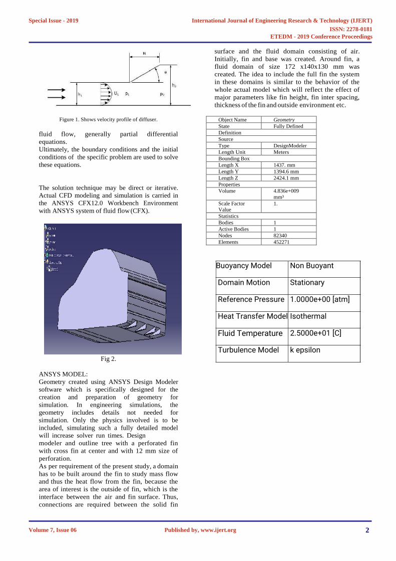
Figure 1. Shows velocity profile of diffuser.
fluid flow, generally partial differential
equations.
Ultimately, the boundary conditions and the initial
conditions of the specific problem are used to solve
these equations.
The solution technique may be direct or iterative.
Actual CFD modeling and simulation is carried in
the ANSYS CFX12.0 Workbench Environment
with ANSYS system of fluid flow (CFX).
Fig 2.
ANSYS MODEL:
Geometry created using ANSYS Design Modeler
software which is specifically designed for the
creation and preparation of geometry for
simulation. In engineering simulations, the
geometry includes details not needed for
simulation. Only the physics involved is to be
included, simulating such a fully detailed model
will increase solver run times. Design
modeler and outline tree with a perforated fin
with cross fin at center and with 12 mm size of
perforation.
As per requirement of the present study, a domain
has to be built around the fin to study mass flow
and thus the heat flow from the fin, because the
area of interest is the outside of fin, which is the
interface between the air and fin surface. Thus,
connections are required between the solid fin
surface and the fluid domain consisting of air.
Initially, fin and base was created. Around fin, a
fluid domain of size 172 x140x130 mm was
created. The idea to include the full fin the system
in these domains is similar to the behavior of the
whole actual model which will reflect the effect of
major parameters like fin height, fin inter spacing,
thickness of the fin and outside environment etc.
Object Name Geometry
State Fully Defined
Definition
Source
Type DesignModeler
Length Unit Meters
Bounding Box
Length X 1437. mm
Length Y 1394.6 mm
Length Z 2424.1 mm
Properties
Volume 4.836e+009
mm³
Scale Factor Value
1.
Statistics
Bodies 1
Active Bodies 1
Nodes 82340
Elements 452271
Buoyancy Model Non Buoyant
Domain Motion Stationary
Reference Pressure 1.0000e+00 [atm]
Heat Transfer Model Isothermal
Fluid Temperature 2.5000e+01 [C]
Turbulence Model k epsilon
International Journal of Engineering Research & Technology (IJERT)
ISSN: 2278-0181
Published by, www.ijert.org
ETEDM - 2019 Conference Proceedings
Volume 7, Issue 06
Special Issue - 2019
2

Settings.RESULT & DISCUSSION:Result Of Diffuser section atangle of 10 Degree:Velocity:
Fig 4(a).Maximum velocity is 123.4 m/sfor the ZY middle plan sectionand for this the drag force is117.315 N.
Pressure Distribution :
Fig 4(b).
Turbulence kinetic Energy:
Fig 4(c).
Result for when Diffuser section at 11Degree:Velocity distribution:
Fig 5(a).
Pressure Distribution:
Fig 5(b).
Turbulence Kinetic Energy:
International Journal of Engineering Research & Technology (IJERT)
ISSN: 2278-0181
Published by, www.ijert.org
ETEDM - 2019 Conference Proceedings
Volume 7, Issue 06
Special Issue - 2019
3

Fig 5(c).
Result for when diffuser section at 12degree :Velocity distribution:
Fig 6(a)
Pressure Profiles:
Fig 6(b).
Turbulence Kinetic Energy :
Fig 6(c).
CONCLUSION:
Angle Velocity(m/s)
TurbulenceKE(m2/s2)
Drag(N)
10 123.4 420 117.315
11 122.99 404.4 128.308
12 123.33 404.5 103Table 1.
From the investigation it wasobserved that the change of diffuserangle (10,11,12,) has a greatinfluence on wake of the underbodyflow. The drag force decreasingwhile increasing diffuser sectionangle. increasing diffuser anglewhich is reducing turbulence kineticenergy and drag force values.
Comparing all these result valueangle 12 Degree which givemaximum velocity and lowturbulence Kinetic energy valuewhich reducing drag force to 103N.This angle give maximum efficiency.
International Journal of Engineering Research & Technology (IJERT)
ISSN: 2278-0181
Published by, www.ijert.org
ETEDM - 2019 Conference Proceedings
Volume 7, Issue 06
Special Issue - 2019
4

REFERENCES:
[1]. Johan Levin, Rikard Rigdal.Aerodynamic
analysis of drag reduction devices on the underbody
for SAAB 9-3 by using CFD, Chalmers University of
Technology, ISSN 1652-8557, 2011.
[2]. Hu, X., Zhang, R., Ye, J., Yan, X., &
Zhao, Z. (2011). Influence of Different Diffuser
Angle on Sedan's Aerodynamic Characteristics.
Physics Procedia, 22, 239-245.
[3].
Aljure,
D.
E.,
Lehmkuhl,
O.,
Rodriguez, I., &
Oliva, A. (2014). Flow and turbulent structures
around simplified car models. Computers & Fluids,
96,
122-135.
[4]. Huminic, A., Huminic, G., & Soica, A. (2012).
Study of aerodynamics for a simplified car model
with the underbody shaped as a Venturi
nozzle.International Journal of Vehicle Design,
58(1), 15-32.
[5].
Yamazaki,
S.,
Motojima,
S.,
&
Koki,
Y. (1994).
The effect of a moving belt for the ressure on the
underbody of a competition
vehicle.
JSAE
Review,
15(2), 171-175.
International Journal of Engineering Research & Technology (IJERT)
ISSN: 2278-0181
Published by, www.ijert.org
ETEDM - 2019 Conference Proceedings
Volume 7, Issue 06
Special Issue - 2019
5