Embed Size (px)
Citation preview
Page 1
Design & Construction Specification for Northumbrian Water Group
(including Northumbrian Water and Essex & Suffolk Water)
Version 1 4 December 2020
Page 2
CONTENTS ............................................................................................ Page
1. Scope.............................................................................................................................. 5
2. Responsibilities ............................................................................................................. 5
3. Terminology ................................................................................................................... 5
4. Charging ......................................................................................................................... 6
5. Abbreviations ................................................................................................................. 6
6. Nomenclature ................................................................................................................. 7
7. Reference Documents ................................................................................................... 8
8. Construction (Design & Management) Regulations 2015 (CDM) ................................ 8
8.1 General ............................................................................................................................ 8
8.1.1 Pre-Construction Phase Plan ........................................................................................... 9
8.2 Collaborative Design ........................................................................................................ 9
8.3 Non-Contestable Work – Installation of District Meter or Pressure Reduction Equipment 9
9. Design Process ............................................................................................................ 10
9.1 Minimum Information Required from Developers ........................................................... 10
9.2 Point of Connection (PoC) Requests ............................................................................. 10
9.3 Annual Contestability Summary ..................................................................................... 11
9.4 Activities shaded green in the ACS ................................................................................ 13
9.5 Activities shaded amber in the ACS ............................................................................... 13
9.6 Activities shaded red in the ACS .................................................................................... 15
9.7 Design Submissions to Water Company ........................................................................ 15
9.8 Design Proposal ............................................................................................................ 16
9.9 Drawing Standards ........................................................................................................ 16
9.10 Drawing Legend ............................................................................................................ 18
9.11 Design & Construction Variations .................................................................................. 18
9.11.1 Minor Variations ............................................................................................................. 18
10. Pipe Sizing Methodology ............................................................................................ 19
10.1 Permitted Pipe Diameters, Pressure Ratings and Permissible Materials. ....................... 19
10.2 Principles of Sizing of Water Mains ................................................................................ 20
10.3 Indicative Pipe Diameter Selection ................................................................................ 21
10.4 Domestic Hydraulic Demand Calculations ..................................................................... 22
10.5 Calculations for Multi-Occupancy Building and Industrial/Commercial Domestic Use .... 23
10.6 Process Water ............................................................................................................... 24
10.7 Pressure and Flow ......................................................................................................... 24
10.7.1 Source Pressure ............................................................................................................ 24
10.7.2 Pressure and Flow ......................................................................................................... 24
10.7.3 Velocity .......................................................................................................................... 24
10.7.4 Calculating Headloss through the Network .................................................................... 25
Page 3
10.7.5 Topography ................................................................................................................... 25
10.8 Selection of Materials for Contaminated Ground ............................................................ 25
10.8.1 Ground contamination during construction ..................................................................... 25
11. Water Main Design and Construction Principles....................................................... 26
11.1 Design Accreditation ...................................................................................................... 26
11.2 Construction (pre-start) .................................................................................................. 26
11.3 Routing and Positioning Principles ................................................................................. 26
11.4 Depth of Self-Laid Main ................................................................................................. 28
11.5 Water Quality Considerations ........................................................................................ 28
11.6 Mains Fittings ................................................................................................................ 29
11.7 Controlling Valves and Valve Operation ......................................................................... 29
11.8 Washout and Fire Hydrants ........................................................................................... 30
11.9 Air Valves ...................................................................................................................... 30
11.10 District Metered Areas and Boundary Valves ................................................................. 30
11.11 Sustainable Drainage Systems (SuDS) Considerations ................................................. 30
11.12 Double Spade Valves .................................................................................................... 31
11.13 Rights of Access ............................................................................................................ 31
12. Service Pipe Design and Installation .......................................................................... 32
12.1 Routing, Positioning and Location .................................................................................. 33
12.2 Depth of Services .......................................................................................................... 34
12.3 Sizing of Services .......................................................................................................... 34
12.4 Location of Boundary Boxes .......................................................................................... 34
12.5 Supplies to Multi Occupancy Buildings .......................................................................... 35
12.6 Services to Multi Storey Buildings .................................................................................. 35
12.7 Additional Requirements for Supplies to Buildings Other Than Domestic Dwellings ...... 35
13. Civil Engineering Considerations ............................................................................... 36
13.1 General .......................................................................................................................... 36
13.2 Marker Tape and Tracer Tape ....................................................................................... 36
13.3 Indicator Posts and Marker Plates ................................................................................. 36
13.4 Chambers and Covers ................................................................................................... 36
13.5 Bedding and Backfill ...................................................................................................... 36
13.6 Reinstatement of Highway ............................................................................................. 37
13.7 Ducts ............................................................................................................................. 37
14. Metering Requirements ............................................................................................... 37
14.1 Standard Domestic Metering for Individual Dwellings and Multi Occupancy buildings .... 37
15. Water for Firefighting .................................................................................................. 38
15.1 Fire and Rescue Service (FRS) Consultation................................................................. 38
15.2 Location and Flow from Hydrants .................................................................................. 38
15.3 Dedicated Fire Mains ..................................................................................................... 38
Page 4
15.4 Fire Sprinkler Systems ................................................................................................... 38
16. As Laid (As Constructed) drawings ........................................................................... 39
17. Self-Laid Main and Services Commissioning ............................................................ 40
17.1 Mains Flushing .............................................................................................................. 40
17.2 Mains swabbing ............................................................................................................. 41
17.3 Mains Bacteriological Sampling ..................................................................................... 42
17.4 Pressure testing of Self-Laid Main ................................................................................. 43
18. Water Company Key Contacts .................................................................................... 43
19. Local Practices ............................................................................................................ 44
19.1 Meter Pairing and Commissioning ................................................................................. 44
19.2 Timing of the Generation of Plot Reference Numbers .................................................... 44
19.3 Water Company Design Service Offerings ..................................................................... 44
19.4 Design Self-Certification Scheme .................................................................................. 44
20. Design and Construction Specification Appendices ................................................ 44
21. Schedule of Permissible Materials and Construction ............................................... 45
22. Meter and Service Pipe Policy and Installation ......................................................... 50
22.1 Service pipes ................................................................................................................. 50
22.2 Metering - general requirements .................................................................................... 50
22.3 Metering of individual dwellings ..................................................................................... 50
22.4 Metering of multi-occupancy buildings ........................................................................... 51
23. Standard Arrangement Drawings ............................................................................... 52
23.1 Boundary boxes – installation requirements .................................................................. 52
23.2 Boundary boxes and service pipes – location and pipe responsibilty ............................. 53
23.3 Boundary boxes – installation in soft ground .................................................................. 54
23.4 Water main (PE) – new PE branch connection and valve arrangement ........................ 55
23.5 Water main (non PE) – new PE branch connection and valve arrangement .................. 56
23.6 Washout installation ....................................................................................................... 57
23.7 Valve installation ............................................................................................................ 58
23.8 Hydrant installation on large diameter main ................................................................... 59
23.9 Large chambers – installation requirements .................................................................. 60
23.10 Internal meter manifold – typical layout .......................................................................... 61
24. Construction Pre-Start Meeting Agenda .................................................................... 62
Appendices ............................................................................................................................. 63
Appendix 1 Water Industry Specifications and Information & Guidance Notes ........................ 63
Appendix 2 British Standards (BS) & BS EN Standards .......................................................... 64
Appendix 3 Other documents .................................................................................................. 65
Page 5
1. SCOPE This document has been prepared to assist practitioners with the planning, design, construction and commissioning of a Self-Laid Main and Service Pipes to supply domestic and industrial/commercial properties. It has been prepared to meet the requirements of the Code and is a template document. The contents of this template are mandatory but there remain a number of areas where there will be variations between individual Water Companies. This template indicates where there is scope for variation and each Water Company will complete those parts of the document and publish a Water Company specific version on its website. That version will govern the requirements in that Water Company’s area. This document should be read in conjunction with the Water Sector Guidance which can be found on Water UK’s website at https://www.water.org.uk/technical-guidance/developers-services/water-asset-adoption/ Over time, it is envisaged that work will be undertaken to reduce the scope of variation between each Water Company’s versions of this document. This will be done through change requests presented to the Water Adoption Code panel (details of which can be found on the Water UK website).
2. RESPONSIBILITIES An SLP and/or Developer wishing to design and/or construct a Self-Laid Main shall comply with the DCS. It is the responsibility of the Water Company to ensure that the relevant sections of the DCS conform to its design standards, completing the sections highlighted in yellow with their own parameters and inserting text where instructed by the square brackets. Completing these sections will create the Water Company’s Design and Construction Specification document which shall be published on the company’s website and which form a contractually binding part of the Water Adoption Agreement. Within this document the words "include" and "including" are to be construed without limitation.
3. TERMINOLOGY In this document the following terms have the stated meanings: Shall: Indicates a mandatory requirement Should: Indicates a strong preference or best practice May: Indicates an option which is not mandatory References to the SLP shall include a reference to its permitted contractor where relevant.
Page 6
4. CHARGING Water Company charges for work relating to the adoption of water assets are based on the Water Company’s published charging arrangements. Funding of any work over and above that which is required to supply a Site (including Network Reinforcement) shall be in accordance with Ofwat’s Charging Rules and therefore any work of this type shall be identified during the design stage and funded appropriately by the Water Company.
5. ABBREVIATIONS AC Asbestos Cement
AOD Above Ordnance Datum
ACS Annual Contestability Summary
CDM Construction, Design and Management Regulations
CESWI Civil Engineering Specification for the Water Industry
CI Cast Iron
COSHH Control of Substances Hazardous to Health
DEFRA Department for Environment, Food and Rural Affairs
DCS Design and Construction Specification
DI Ductile Iron
DMA District Metered Area
DWI Drinking Water Inspectorate
EA Environment Agency
EUSR Energy and Utility Skills Register
FRS Fire and Rescue Service
HAUC Highway Authorities and Utilities Committee
HPPE (PE100) High Performance Polyethylene
HSE Health and Safety Executive
HSWA Health and Safety at Work Act
ICE Institution of Civil Engineers
IGN Information & Guidance Notes
IWater Institute of Water
LR Lloyd’s Register EMEA
MDPE (PE80) medium Density Polyethylene
NCO(W) Water Network Construction Operations
NRSWA New Roads and Street Works Act
NVQ National Vocational Qualification
OFWAT the Water Services Regulatory Authority
PE/AL/PE Polyethylene Aluminium Composite Barrier Pipe
PE Polyethylene
PE80 Medium Density Polyethylene
PE100 High Density Polyethylene
PPE Personal Protective Equipment
PPM Parts Per Million
PVC Poly Vinyl Chloride
Page 7
SDR Standard Dimension Ration - Outside diameter / Wall Thickness
COMPETENCY Safety and Technical Competency
TA Technical Advisor
WIA Water Industry Act
WIRS Water Industry Regulation Scheme
WIS Water Industry Specifications
WRAS Water Regulation Advisory Service
6. NOMENCLATURE v - Volume, Litres A - Area, metres squared V - Velocity, metres per second Q - Flow, litres per second t - Time, in seconds P - Pressure, in Bar H - Static Head, in metres hL - Head loss due to Friction, metres L - Length in metres G - Gravitational acceleration, ms-2 D - Diameter, millimetres i - Hydraulic Gradient, metres per metre
- Kinematic viscosity of fluid, m²/s Ks - Effective roughness value, millimetres Qt - Design Flow, l/s LU - Loading Units E - Equivalent length, metres Ω - Soil Resistivity, Ohm -cm
Page 8
7. REFERENCE DOCUMENTS See Appendix 1 for a comprehensive list of reference documents. The documents in this list are relevant to design and construction standards but may not necessarily be referred to expressly in this DCS. If there is a conflict between any of those standards and the DCS, the DCS shall take precedence unless otherwise agreed by the parties. A list of accredited SLPs can be found here: https://www.lr.org/en/utilities/water-industry-registration-scheme-wirs-wirsae/search/
8. CONSTRUCTION (DESIGN & MANAGEMENT)
REGULATIONS 2015 (CDM)
8.1 General The relevant sections of the CDM Regulations (2015) apply to all design works carried out by or on behalf of the Water Company – both the Water Company’s representative (Approving Design Engineer) and the SLP’s representative (SLP Designer) are Designers under CDM Regulations when the design of Self-Lay Works is being generated and accepted for adoption. When carrying out work specific to a Site, neither the SLP Designer nor the Approving Design Engineer would be expected to be the Principal Designer. The Client (Developer) has a responsibility to formally appoint a competent Principal Designer and Principal Contractor for the Site. The Principal Designer shall provide oversight of all design activity in accordance with the Regulations. To comply with CDM Regulations (2015) it is expected that, prior to release for construction, the SLP Designer shall:
Ensure that the design avoids or addresses at source foreseeable risks to health and safety
Give priority in the design to measures which will protect all people associated / or affected by
the project
Ensure that the design includes adequate information about any aspect of the project, structure,
and all materials which may affect the health and safety of persons during construction and
during any subsequent maintenance operations
make the Water Company aware of any non-standard method of operation applicable to the
Self-Lay Works
Record non-standard residual risks including chemical or oil pipeline crossing, working at height
which cannot be designed out, in the project file, and a copy passed to the Principal Designer
and Water Company
Co-operate with all parties concerned with planning and design for the project
The SLP responsible for the proposed construction shall be made aware of the risks identified by the Designer and the control measures required to reduce the risks to an acceptable level. A design which is prepared or modified outside Great Britain, for use in work to which CDM 2015 applies, must comply with “Regulation 9 – Duties of Designers” and the person who commissions the work is responsible for ensuring Regulation 9 is complied with.
Page 9
8.1.1 Pre-construction phase plan
A Pre-construction phase plan shall be created at the design stage. This plan shall include the following: –
Description of works.
Proposed time scales of works within the project.
Details of risk and required control measures.
Information required by Principal Contractor to demonstrate competence of resources.
Information for preparing the health and safety plan for the construction phase
The pre-construction phase plan shall be passed to the Principal Contractor for inclusion and development of their Construction Phase Plan before work commences on Site. The need for the plan arises from the requirements of CDM. HSE leaflet INDG411 (rev1), published 04/15 states:
“Ensure a construction phase plan is in place”
The principal contractor (or contractor if there is only one contractor) has to draw up a plan explaining how health and safety risks will be managed. This should be proportionate to the scale of the work and associated risks and you should not allow work to start on site until there is a plan”.
8.2 Collaborative design On occasion Water Companies may produce indicative design drawings relative to the proposed Site layout for costing, routing or tendering purposes. Where this is the case the design drawing should be clearly marked as “Not for Construction” and/or an accompanying document produced which states precisely what has been considered when producing that layout drawing. The Water Company shall detail any services supplied and the rates chargeable in its published Charging Arrangements.
8.3 Non-Contestable Work – installation of district meter or
pressure reduction equipment Sites may require a Source of Water connection from a high-pressure Water Main and, in such a case, the Water Company may require a pressure reducing valve or district meter installation as part of the Non-contestable Work and Services (typically with branch connection). In this instance, the Water Company shall assume Designer responsibility under CDM Regulations for this element of the work solely where it is off Site (outside of the site boundary) and out of scope of the contestable activity to be undertaken by the SLP. If this installation is required to be installed within the Site boundary due to the proximity of the Source of Water Connection, then design responsibility will be determined between the parties by written agreement.
Page 10
9. DESIGN PROCESS
9.1 Minimum information required from developers Appendix E (Minimum Information) of the WSG contains a complete statement of information requirements at all stages of the adoption process. At the design stage, the SLP may be accredited to carry out the design activity or may request the Water Company carry out this activity if the Water Company offers this service as a Local Practice under section 4.6 of the WSG. An application form available from the Water Company website shall be completed which is used to identify the minimum inflow of information to begin the design process relevant to the route of delivery of the Design.
9.2 Point of Connection (PoC) requests At the determined PoC, the connection is typically made by an under-pressure connection (UPC) to ensure disruption to existing customers is minimised. However operational considerations may dictate that the Water Company determines that a UPC is not suitable and that the connection will require a tee piece to be installed. This involves isolating the Network and cutting a section of the existing Network out to insert same, and additional valves may also be installed in conjunction, on the existing Network. Such a connection will be considered as Non-contestable work. Where additional valves on the existing Network, typically installed at the same time as a connection involving cutting in to the existing Network, are not specifically required in the design for the new Self-Laid Main (i.e. to supply a Site) but which the Water Company requires to be installed for operational reasons; then these valves shall be considered as Network Reinforcement work. The Water Company may identify a supply need in respect of future development that means that it requires Network Reinforcement to be incorporated within the SLP’s design (e.g. via the planning system, local authority development plans or developer engagement). In these circumstances, the Water Company shall initiate discussions with the SLP when a Point of Connection (PoC) is issued, or at the earliest opportunity if a Point of Connection (PoC) has already been issued. Similarly, where the Water Company identifies a need for the improvement or upgrade of the Network as part of the Self-Lay Works, the Water Company shall initiate suitable discussions with the SLP when a Point of Connection (PoC) is issued, or at the earliest opportunity if a Point of Connection (PoC) has already been issued. These requirements may be incorporated by agreement into the final SLP Accepted Design. If an alternative PoC is required and is evident particularly during the early stages of design by the Water Company to a PoC (that may have been provided also by an SLP/Developer) for technical and/or supply reasons the Water Company shall provide the SLP designer with an explanation and identify related options and requirements. If Network Reinforcement work is deemed necessary by the Water Company relative to supplying the Site this shall be identified by the Water Company to the SLP and/or Developer during the initial design stage; and considered by the SLP designer in designing the layout of the Self-Lay Works. The requirement for detailed design drawings and related information relative to design and/or construction activities shall be agreed between the parties to the WAA and included in Schedule1 of the WAA.
Page 11
9.3 Annual Contestability Summary
9.3.1 This section contains information about how the Water Company assesses contestability of
particular work categories.
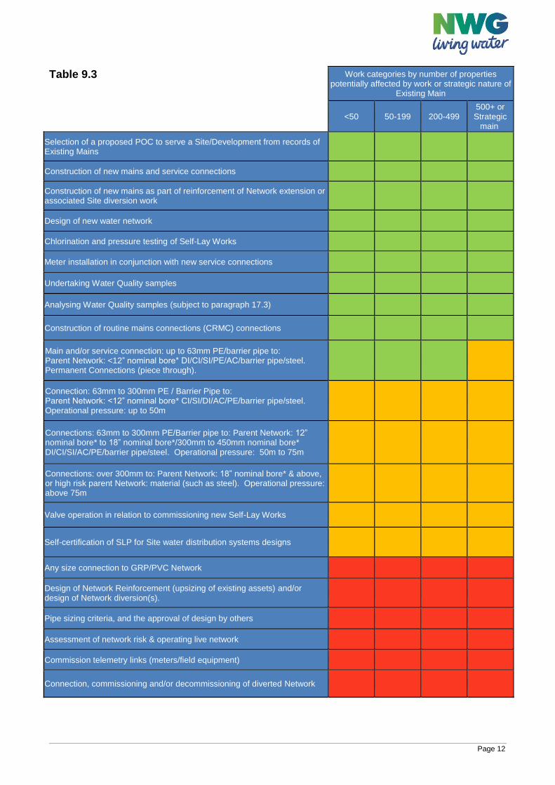
9.3.2 Set out below at Table 9.3 is the summary that all Water Companies will publish at the date
of implementation of this DCS and at least annually thereafter. This will be known as an
“Annual Contestability Summary (“ACS”) and it will be a Water Company specific variant of
the standard template appearing at table 3.2 of the WSG.
9.3.3 No Water Company’s ACS will allow fewer activities to be Contestable Work and Services
than are set out on that template, as amended from time to time.
9.3.4 Each Water Company’s ACS will be accompanied by indicative information about the steps
that an SLP would be required to take to carry out the higher risk tasks shaded amber on
Table 9.3.
9.3.5 It is expected that over time, the template ACS will be modified in the light of experience and
of changing accreditation requirements, to increase the scope of Contestable activities
available for SLPs to undertake.
9.3.6 The activities appearing in green on Table 9.3 shall always be Contestable (i.e. marked
green).
9.3.7 The works and services designated Contestable by a Water Company under its ACS shall
not, in any event, be fewer than those permitted to be carried out by SLPs in that Water
Company’s area before the date on which the Guidance comes into effect.
9.3.8 In advance of publication, the ACS will be discussed with relevant Customers in a Water
Company’s area. Each Water Company shall publish its ACS on its website no later than
four (4) weeks before it takes effect, to allow sufficient time for SLPs to amend their
processes, if required.
9.3.9 A Water Company will explain within its ACS where it has used its discretion to include an
activity within the red category and ensure this is published on its website.
9.3.10 Where providing an adequate Site supply requires Network Reinforcement, elements of this
work should be considered as Contestable subject to the scope of works required and
impact on existing end-user customers. This concerns additional works to extend from the
nearest Point of Connection of suitable size to a more distant Point of Connection specified
by the Water Company. Charges shall by agreement between the SLP and the Water
Company and with reference to Water Company Charging Arrangements.
Page 12
Table 9.3
Work categories by number of properties potentially affected by work or strategic nature of
Existing Main
<50 50-199 200-499 500+ or Strategic
main
Selection of a proposed POC to serve a Site/Development from records of Existing Mains
Construction of new mains and service connections
Construction of new mains as part of reinforcement of Network extension or associated Site diversion work
Design of new water network
Chlorination and pressure testing of Self-Lay Works
Meter installation in conjunction with new service connections
Undertaking Water Quality samples
Analysing Water Quality samples (subject to paragraph 17.3)
Construction of routine mains connections (CRMC) connections
Main and/or service connection: up to 63mm PE/barrier pipe to: Parent Network: <12” nominal bore* DI/CI/SI/PE/AC/barrier pipe/steel. Permanent Connections (piece through).
Connection: 63mm to 300mm PE / Barrier Pipe to: Parent Network: <12” nominal bore* CI/SI/DI/AC/PE/barrier pipe/steel. Operational pressure: up to 50m
Connections: 63mm to 300mm PE/Barrier pipe to: Parent Network: 12” nominal bore* to 18” nominal bore*/300mm to 450mm nominal bore* DI/CI/SI/AC/PE/barrier pipe/steel. Operational pressure: 50m to 75m
Connections: over 300mm to: Parent Network: 18” nominal bore* & above, or high risk parent Network: material (such as steel). Operational pressure: above 75m
Valve operation in relation to commissioning new Self-Lay Works
Self-certification of SLP for Site water distribution systems designs
Any size connection to GRP/PVC Network
Design of Network Reinforcement (upsizing of existing assets) and/or design of Network diversion(s).
Pipe sizing criteria, and the approval of design by others
Assessment of network risk & operating live network
Commission telemetry links (meters/field equipment)
Connection, commissioning and/or decommissioning of diverted Network
Page 13
*Notes:
1 All references to PE are to all Polyethylene pipe materials 2 PE pipe sizes are identified by outside (OD) diameter and other pipe materials and sizes
refer to internal (nominal bore) diameters 3 Strategic main defined by reference to potential impact of work on key customer such as a
hospital 4 See further paragraph 11.7 of the DCS
Northumbrian Water Group’s (NWG) ACS is published as a separate document on the website and available via the links below. https://www.nwl.co.uk/services/developers/water-services/water-mains/self-lay/ https://www.eswater.co.uk/services/developers/water-services/water-mains/self-lay/
9.4 Activities shaded green in the ACS 9.4.1 All activities shaded green in the above table are capable of being performed by SLPs. 9.4.2 These green-shaded activities will apply where the SLP has the relevant WIRS or other
accreditation (see section 7 of the WSG). Where further activities are accredited by WIRS, such activities shall be marked as green in the above table once approved by the Codes Panel.
9.4.3 The Water Company will set out the procedures it has in place relating to connections to
the Existing Main and the forms supporting this. These will be published on the Water Company’s website.
9.4.4 Changes will be brought about by the procedures set out in the Water Sector Guidance
Section 11 – Governance. 9.4.5 References to the Final Connection of the Self-Laid Main to the Existing Main on the
Network are: a) of an under-pressure type connection and/or,
b) a connection to a previously installed temporary valve-controlled washout installed in
conjunction with the connection to the Existing Mains Network at the POC to supply
the Site or Development, and/or
c) a connection to a previously installed valve-controlled washout, which has been
installed on a Self-Laid Main for a future connection off such main.
Where references to the Final Connection of the Self-Laid Main to the Existing Main on the Network require a section to be isolated by a shut (to enable it to be cut-out to install a connection point), and/or if a new branch tee is required to be cut into a Self-Laid Main and the relevant assets are subsequently adopted by the Water Company (and therefore forms part of the Network), then such connections are excluded from activities shaded green.
9.5 Activities shaded amber in the ACS 9.5.1 The activities shaded amber shall be capable of being performed by an SLP in the area
of an individual Water Company where the SLP complies with the requirements of the
Water Company as set out below. Such publication shall include information about
Page 14
control measures required to allow the work to be performed. The following paragraphs
set out how publication of such information is to be approached.
9.5.2 The Water Company may require additional evidence of competence to carry out activity
and/or require the SLP to follow an operational process equivalent to one that the Water
Company’s direct labour or term contractor would be required to follow.
9.5.3 The Water Company’s requirements will relate to the specific Site and will take account
of the type of connection involved; the location of the connection; the strategic
importance of the main Network to be connected to; the potential impact on end user
customers; risk to water quality and regulatory impact/consideration; and the resources
the SLP proposes to use.
9.5.4 The company will set out the information it needs from the SLP regarding its
Accreditation and how its general and specific operations, resources, and procedures will
protect the company from any risk of interruption of supply to its end-user customers
and/or to water quality. These requirements will be equivalent to those that the Water
Company’s direct labour or term contractor would be required to follow.
9.5.5 The SLP will need to demonstrate its competence or relevant experience to undertake
this activity. This may be demonstrated where the Water Company has previously
observed relevant Self-lay Works having been carried out by the SLP or by the SLP
providing details of similar work that it has carried out to a satisfactory standard for other
Water Companies.
9.5.6 Water Company requirements relative to valve operation in relation to commissioning of
Self-Lay Works, a contestable activity, shall apply as set out in paragraph 11.7
9.5.7 The Water Company will set out below the procedures it has in place to allow
connections to the Existing Main and the forms supporting this. These will be published
on the Water Company’s website.
9.5.8 Where an SLP intends to make service connections to an Existing Main and there are no
Self Laid Mains to be constructed, an adoption agreement must be entered into in
advance of making those connections.
9.5.9 To undertake tasks shaded amber in the ACS, the SLP will be required to provide NWG
with a satisfactory Method Statement and Risk Assessment for the proposed activities.
9.5.10 NWG experience indicates that there is an elevated incidence of bursts on networks
constructed of AC and PVC material, thus heightening the risk of structural failure during
connection activity. Where SLPs request to make connections to AC mains, NWG will
require Risk Assessment and Method Statement that demonstrates that the risk of
structural failure of the main has been substantially removed.
9.5.11 NWG experience indicates that there is an elevated incidence of structural failure when
making under pressure connections where the connecting pipe is the same diameter as
the host main. Where SLPs request to make such connections NWG will require Risk
Assessment and Method Statement that demonstrates that the risk of structural failure of
the main has been substantially removed.
Page 15
9.6 Activities shaded red in the ACS 9.6.1 The Water Companies have concluded that connections shaded red in table 9.3 are of
such a high risk that they are unlikely to be contestable in most conceivable
circumstances.
9.6.2 However, if an SLP wishes to carry out this work, it shall contact the Water Company
directly to determine whether conditions can be agreed that enable the SLP to carry out
the requested activity
9.7 Design submissions to water company Design submissions shall be submitted to the Water Company along with all supporting information as set out in Appendix E – Minimum Information of the WSG. Any activity classed as Non-Contestable shall be confirmed in writing by the Water Company following discussion between the Water Company and SLP upon the issue of a Design Acceptance. NWG offers a discount to customers that design and build houses to promote a lower consumption of water. NWG will discount the water infrastructure charge in the event that evidence is provided to show a house is to be built to achieve a consumption of no more than 105 litres per person per day, currently. Discounts for eligible houses can be applied for when submitting the relevant application forms for new water mains and service connections. Application forms and guidance can be located by following the links below: https://www.nwl.co.uk/services/developers/water-services/ https://www.eswater.co.uk/services/developers/water-services/
Page 16
9.8 Design proposal When preparing a water network design proposal, the SLP Designer shall: 1 Select appropriate materials for the Self-Laid Main and Service Pipes. 2 Determine the legal land ownership boundary of the Site. 3 Produce a drawing to an appropriate scale to show the layout and route of the Self-Laid Mains
and Service Pipes and proposed meter arrangements (relative to Service Pipe entry points) in accordance with this Design and Construction Specification.
4 Provide all related material requirements and details as required by this Design and Construction Specification.
5 Calculate demands and size all Service Pipes in line with this Design and Construction
Specification (see also paragraph 10.2).
6 Size the Self-Laid Mains across the Site as may be required to meet the requirements of the
Site and any Development relative to the Site, following discussion with the Water Company.
Any Water Company requirements will be communicated after such discussion has taken
place. See further section 10.2.
7 Identify the agreed Point of Connection and determine by agreement with the Water Company
all work that is Contestable and Non-contestable.
8 Design the appropriate number of Self-Laid Main fittings required to control the Network and
the Self-Lay Works.
9 Identify any sections of Self-Laid Mains that require easements or wayleaves.
10 Identify any Special Engineering Difficulties as appropriate.
Water companies shall share with the SLP any pipe size methodology where this is requested by the SLP
9.9 Drawing standards The Water Company may supply the SLP with templates to assist in the standardisation of design drawings. If this is not available, then the SLP should provide their own design template. Design and as-laid (as constructed) drawings shall be submitted to the Water Company electronically in both CAD and PDF format, by agreement with the Water Company, for incorporation into the Water Company’s corporate geographical information system (GIS). Design drawings shall show all asset locations, size and specification in a clear and unambiguous format. Should enlargements, blow ups or schematics be required in order to ensure a clear and unambiguous layout then these shall be incorporated within the design submission. Design drawings shall include and clearly show, as a minimum:
1. Proposed off-site Self-Laid Mains to Point of Connection to the Network
2. AOD at POC and highest point of the site including Site topography can be provided
separately
3. Proposed Self-Laid Mains, including position of sluice valves, washouts, hydrants, air valves
and any other fittings required
4. Any requirements for the protection and/or diversion of the existing Network.
5. Material and size of each Self-Laid Main
Page 17
6. Depth of each Self-Laid Main when installation depth is not in accordance with Streetworks
UK guidance (subject to agreement by Water Company).
7. The Self-Lay Works and Water Company Works (Contestable/Non-contestable activities)
8. Position of existing buildings or features relative to the design proposal for reference
(minimum of 3 points on the drawing to enable triangulation)
9. Individually numbered plots
10. Location of Service Pipes, showing size if above 25mm
11. Service Pipe entry points
12. Location of boundary boxes, manifold boxes and any meter chambers as applicable
13. Type of service connection for each plot, i.e. wall box, boundary box, manifold, internal
14. Hydrants adoptable by the Fire and Rescue Service
15. Location of any ducts
16. Any Special Engineering Difficulties
17. Areas of contamination where protective pipework is required
18. Future demand, or Development, or phase adjacent to Site as identified by the Water
Company or Developer and its Point of Connection relative to the proposed Self-Laid Main
19. North point
20. Site boundary
21. Roads / highways/service strips (adopted or proposed for adoption)
22. Change in ground level
23. Service strips, wayleaves and easements required for the construction, operation and
maintenance of the Self-Laid Main
24. Significant environmental and health and safety hazards
25. Contestable/Non-contestable works annotated
26. A drawing legend/title block
The above list represents best practice and in some cases, not all such drawings will be required by
the Water Company. Water Companies will justify differences in documentation requirements
between requisitioned and self-lay schemes.
Page 18
9.10 Drawing legend The drawing legend shall contain:
1. SLP contact details
2. Developer contact details
3. Company carrying out the design (if different to above)
4. SLP Designer name
5. CAD operator name
6. Site name
7. Site address
8. Ordnance Survey coordinates
9. Industry recognised scale of the drawing
10. Drawing/revision reference number
11. Water Company reference number
12. Approval status i.e.
a. Proposed design (not for construction)
b. Water Company approved design (not for construction)
c. Approved for Construction
9.11 Design & construction variations Changes to the design/construction of the Self-Lay Works (including those due to site conditions, changes to the Site made by the Developer, etc. which require the re-issue of either the SLP Accepted Design or the Water Company Design shall be considered a Significant Variation. The Parties shall comply with the process in clause 19 of the WAA (Variations).
9.11.1Minor variations
Minor variations shall be agreed in writing between the Parties. Minor variations shall be classed as changes to the proposed Self-Laid Mains and/or Service Pipe design with no significant impact on the maximum scope of work measured by the number of plots on the Site i.e. if there is no change in the number of plots or the financial transaction, the change is classed as minor.
Page 19
10 PIPE SIZING METHODOLOGY This section covers permitted pipe sizes and methodology of pipe size determination.
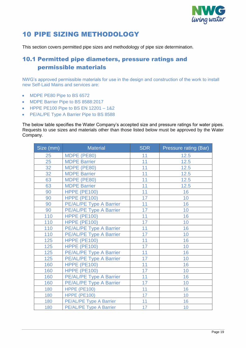
10.1 Permitted pipe diameters, pressure ratings and
permissible materials NWG’s approved permissible materials for use in the design and construction of the work to install new Self-Laid Mains and services are:
MDPE PE80 Pipe to BS 6572
MDPE Barrier Pipe to BS 8588:2017
HPPE PE100 Pipe to BS EN 12201 – 1&2
PE/AL/PE Type A Barrier Pipe to BS 8588
The below table specifies the Water Company’s accepted size and pressure ratings for water pipes. Requests to use sizes and materials other than those listed below must be approved by the Water Company.
Size (mm) Material SDR Pressure rating (Bar)
25 MDPE (PE80) 11 12.5
25 MDPE Barrier 11 12.5
32 MDPE (PE80) 11 12.5
32 MDPE Barrier 11 12.5
63 MDPE (PE80) 11 12.5
63 MDPE Barrier 11 12.5
90 HPPE (PE100) 11 16
90 HPPE (PE100) 17 10
90 PE/AL/PE Type A Barrier 11 16
90 PE/AL/PE Type A Barrier 17 10
110 HPPE (PE100) 11 16
110 HPPE (PE100) 17 10
110 PE/AL/PE Type A Barrier 11 16
110 PE/AL/PE Type A Barrier 17 10
125 HPPE (PE100) 11 16
125 HPPE (PE100) 17 10
125 PE/AL/PE Type A Barrier 11 16
125 PE/AL/PE Type A Barrier 17 10
160 HPPE (PE100) 11 16
160 HPPE (PE100) 17 10
160 PE/AL/PE Type A Barrier 11 16
160 PE/AL/PE Type A Barrier 17 10
180 HPPE (PE100) 11 16
180 HPPE (PE100) 17 10
180 PE/AL/PE Type A Barrier 11 16
180 PE/AL/PE Type A Barrier 17 10
Page 20
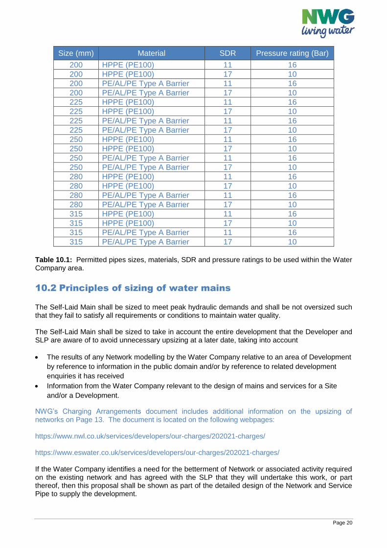
Size (mm) Material SDR Pressure rating (Bar)
200 HPPE (PE100) 11 16
200 HPPE (PE100) 17 10
200 PE/AL/PE Type A Barrier 11 16
200 PE/AL/PE Type A Barrier 17 10
225 HPPE (PE100) 11 16
225 HPPE (PE100) 17 10
225 PE/AL/PE Type A Barrier 11 16
225 PE/AL/PE Type A Barrier 17 10
250 HPPE (PE100) 11 16
250 HPPE (PE100) 17 10
250 PE/AL/PE Type A Barrier 11 16
250 PE/AL/PE Type A Barrier 17 10
280 HPPE (PE100) 11 16
280 HPPE (PE100) 17 10
280 PE/AL/PE Type A Barrier 11 16
280 PE/AL/PE Type A Barrier 17 10
315 HPPE (PE100) 11 16
315 HPPE (PE100) 17 10
315 PE/AL/PE Type A Barrier 11 16
315 PE/AL/PE Type A Barrier 17 10
Table 10.1: Permitted pipes sizes, materials, SDR and pressure ratings to be used within the Water Company area.
10.2 Principles of sizing of water mains The Self-Laid Main shall be sized to meet peak hydraulic demands and shall be not oversized such that they fail to satisfy all requirements or conditions to maintain water quality. The Self-Laid Main shall be sized to take in account the entire development that the Developer and SLP are aware of to avoid unnecessary upsizing at a later date, taking into account
The results of any Network modelling by the Water Company relative to an area of Development
by reference to information in the public domain and/or by reference to related development
enquiries it has received
Information from the Water Company relevant to the design of mains and services for a Site
and/or a Development.
NWG’s Charging Arrangements document includes additional information on the upsizing of networks on Page 13. The document is located on the following webpages: https://www.nwl.co.uk/services/developers/our-charges/202021-charges/ https://www.eswater.co.uk/services/developers/our-charges/202021-charges/ If the Water Company identifies a need for the betterment of Network or associated activity required on the existing network and has agreed with the SLP that they will undertake this work, or part thereof, then this proposal shall be shown as part of the detailed design of the Network and Service Pipe to supply the development.
Page 21
The sizing of pipes for indicative design purposes (e.g. for cost estimates or tendering) may be done using a simple table method for number of properties. However, no reliance shall be placed on this indicative assessment for the purposes of any final design as pipes shall be designed in accordance with the principles and criteria stated below. The sizing of pipes for detailed final design should be based upon a hydraulic calculation using the calculated peak demand and the Hazen Williams or Colebrook-White Equation.
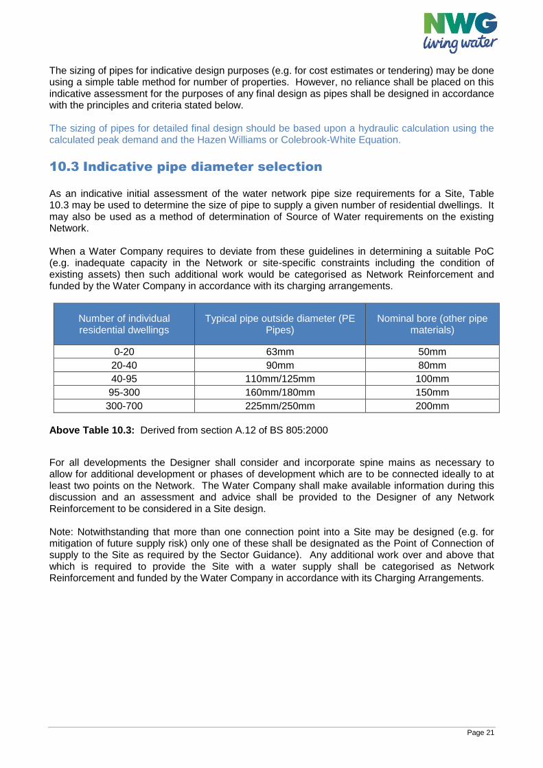
10.3 Indicative pipe diameter selection As an indicative initial assessment of the water network pipe size requirements for a Site, Table 10.3 may be used to determine the size of pipe to supply a given number of residential dwellings. It may also be used as a method of determination of Source of Water requirements on the existing Network. When a Water Company requires to deviate from these guidelines in determining a suitable PoC (e.g. inadequate capacity in the Network or site-specific constraints including the condition of existing assets) then such additional work would be categorised as Network Reinforcement and funded by the Water Company in accordance with its charging arrangements.
Number of individual residential dwellings
Typical pipe outside diameter (PE Pipes)
Nominal bore (other pipe materials)
0-20 63mm 50mm
20-40 90mm 80mm
40-95 110mm/125mm 100mm
95-300 160mm/180mm 150mm
300-700 225mm/250mm 200mm Above Table 10.3: Derived from section A.12 of BS 805:2000
For all developments the Designer shall consider and incorporate spine mains as necessary to allow for additional development or phases of development which are to be connected ideally to at least two points on the Network. The Water Company shall make available information during this discussion and an assessment and advice shall be provided to the Designer of any Network Reinforcement to be considered in a Site design. Note: Notwithstanding that more than one connection point into a Site may be designed (e.g. for mitigation of future supply risk) only one of these shall be designated as the Point of Connection of supply to the Site as required by the Sector Guidance). Any additional work over and above that which is required to provide the Site with a water supply shall be categorised as Network Reinforcement and funded by the Water Company in accordance with its Charging Arrangements.
Page 22
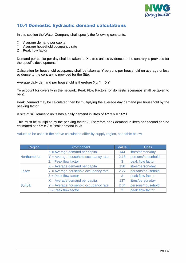
10.4 Domestic hydraulic demand calculations In this section the Water Company shall specify the following constants: X = Average demand per capita Y = Average household occupancy rate Z = Peak flow factor
Demand per capita per day shall be taken as X Litres unless evidence to the contrary is provided for the specific development. Calculation for household occupancy shall be taken as Y persons per household on average unless evidence to the contrary is provided for the Site. Average daily demand per household is therefore X x Y = XY To account for diversity in the network, Peak Flow Factors for domestic scenarios shall be taken to be Z. Peak Demand may be calculated then by multiplying the average day demand per household by the peaking factor. A site of ‘n’ Domestic units has a daily demand in litres of XY x n = nXY l This must be multiplied by the peaking factor Z. Therefore peak demand in litres per second can be estimated at nXY x Z = Peak demand in l/s Values to be used in the above calculation differ by supply region, see table below.
Region Component Value Units
Northumbrian
X = Average demand per capita 144 litres/person/day
Y = Average household occupancy rate 2.18 persons/household
Z = Peak flow factor 3 peak flow factor
Essex
X = Average demand per capita 156 litres/person/day
Y = Average household occupancy rate 2.27 persons/household
Z = Peak flow factor 3 peak flow factor
Suffolk
X = Average demand per capita 137 litres/person/day
Y = Average household occupancy rate 2.04 persons/household
Z = Peak flow factor 3 peak flow factor
Page 23
10.5 Calculations for multi-occupancy building and industrial
and commercial domestic use For houses, the hydraulic demand is calculated as per 10.4 above. NWG defines a “house” to
mean any building or part of a building that is occupied as a private dwelling house or which, if
unoccupied, is likely to be so occupied and, accordingly, includes a flat. This means that the
demand for any parts of a multi-occupancy building that constitute a “house” are calculated in the
same way as per 10.4 above.
For any parts of a multi-occupancy building that do not constitute a “house”, or are industrial
buildings or commercial buildings; NWG uses the Relevant Multiplier calculation below to determine
their domestic demand. The Relevant Multiplier translates that demand into the equivalent number
of households so that the figure can then be used in the equations in 10.4 above.
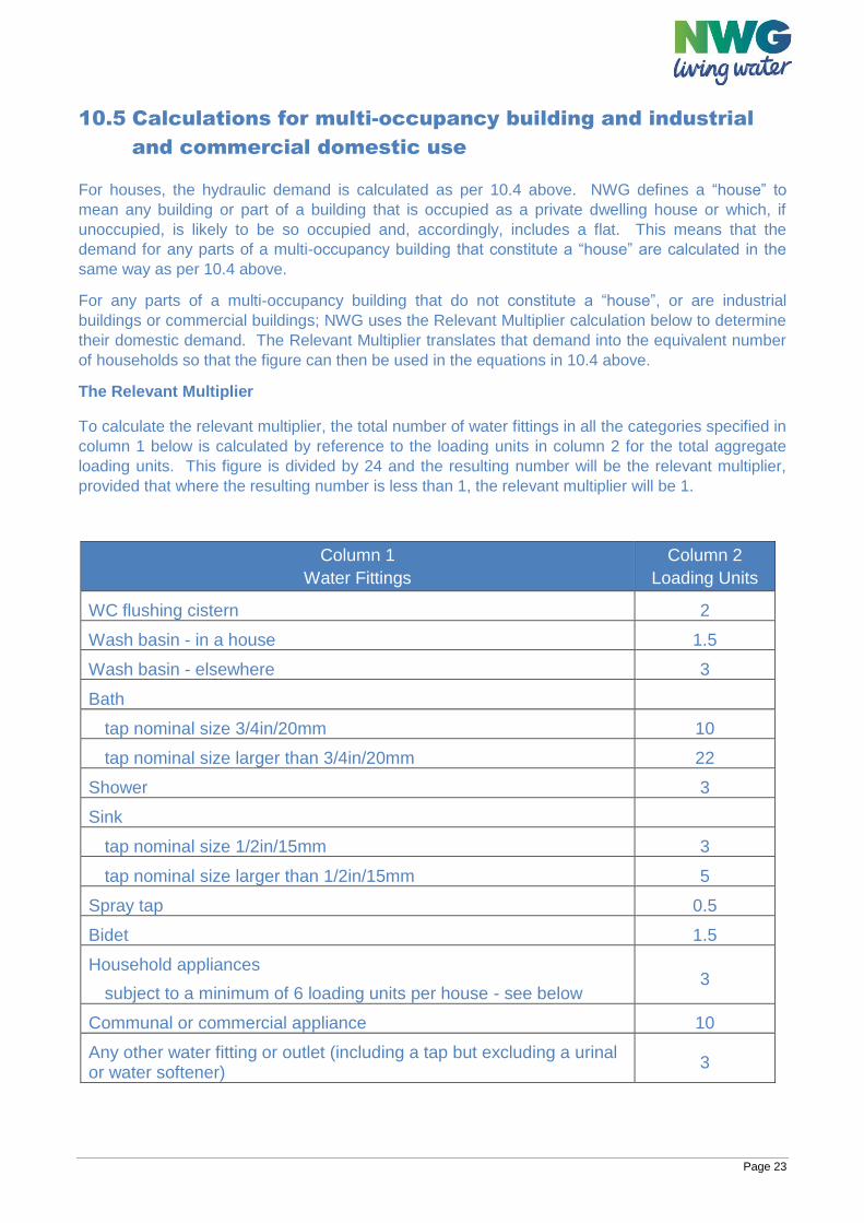
The Relevant Multiplier
To calculate the relevant multiplier, the total number of water fittings in all the categories specified in
column 1 below is calculated by reference to the loading units in column 2 for the total aggregate
loading units. This figure is divided by 24 and the resulting number will be the relevant multiplier,
provided that where the resulting number is less than 1, the relevant multiplier will be 1.
Column 1
Water Fittings
Column 2
Loading Units
WC flushing cistern 2
Wash basin - in a house 1.5
Wash basin - elsewhere 3
Bath
tap nominal size 3/4in/20mm 10
tap nominal size larger than 3/4in/20mm 22
Shower 3
Sink
tap nominal size 1/2in/15mm 3
tap nominal size larger than 1/2in/15mm 5
Spray tap 0.5
Bidet 1.5
Household appliances
subject to a minimum of 6 loading units per house - see below 3
Communal or commercial appliance 10
Any other water fitting or outlet (including a tap but excluding a urinal or water softener)
3
Page 24
10.6 Process water It is expected that the client should provide peak demands given their individual knowledge of the Development. The connection and Self-Laid Mains that are to be installed should then be selected based on their peak demand.
10.7 Pressure and flow
10.7.1 Source pressure
For the purposes of designing the network, the SLP shall check with the Water Company to confirm pressure at the source. During the design stage, if any constraints, e.g. effect on headloss due to an increased AOD relative to a Site and/or Development, are identified by the SLP or the Water Company a workable solution is to be agreed between the Parties.
10.7.2 Pressure and flow
Reference levels of service shall be used to ensure that networks can supply all properties with a minimum pressure and flow at the customer’s communication pipe. Minimum pressure in communication pipe at boundary of property to be serviced based on Ofwat’s Guaranteed Standards Scheme (GSS) is 7 metres head with a flow of 9 litres per minute. In normal operational circumstances Minimum Pressure at a hydrant or nodal point on the system shall be 15 mH or 1.5 Bar Maximum Design Pressure (MDP) which is equal to Design Pressure plus allowance for surge, shall not exceed Pressure Nominal (PN) which is the pressure rating of the lowest rated component in the system. SLP Designers shall clearly state where a component has been used below the Water Company’s standard pressure rating to allow standard System Test Pressures (STP) to be adjusted on site.
10.7.3 Velocity
Minimum peak time velocities in all Pipes shall reach 0.25 msˉ¹ Maximum velocity in Mains shall not exceed 2.0 msˉ¹ Maximum velocity in Service Pipe shall not exceed 2.0 msˉ¹
The methodology for calculating velocity in pipes for detailed final design should be based upon a hydraulic calculation using the Hazen Williams or Colebrook-White Equation.
Page 25
10.7.4 Calculating headloss through the network
For newly designed and constructed Water Mains headloss per 100m shall not exceed 2.0mH, target values shall be between 0.1m/100m and 1.0m/100m The methodology for calculating headloss in pipes for detailed final design should be based upon a hydraulic calculation using the Hazen Williams or Colebrook-White Equation.
10.7.5 Topography
Above Ordnance Datum (AOD) shall be the preferred scale when highlighting level changes on the design drawing. The effect of increased altitudes on a Site shall be taken into consideration by the SLP Designer when low source pressures have been identified by the Water Company. The finished floor level of the highest connection shall for the purposes of the design serve as the additional loss of head when ensuring the reference level of service.
10.8 Selection of materials for contaminated ground Materials for use in contaminated ground shall be selected in accordance with the Water UK Contaminated Land Assessment Guidance. See link in Appendix 3.
10.8.1Ground contamination during construction
If contamination is suspected during construction of the Self-lay Works, the work shall be stopped and be shall be isolated from the potential source of contamination and the incident reported to the Water Company and Developer. An investigation and action plan, which may include a change of pipe material (and/or replacement of the apparatus already installed) shall be agreed with the Water Company before work recommences. The SLP shall ensure that all employees are trained and able to undertake the appropriate actions when working in potentially contaminated land in accordance with health and safety legislation. Consideration should be given to the effect of permeable surfaces on future contamination risk and documented in section 5 of the Contaminated Land Risk Assessment. Additional information regarding NWG’s requirements in relation to contaminated land is located on the following webpages: https://www.nwl.co.uk/services/developers/water-services/water-mains/ukwir-contaminated-land-guidance/ https://www.eswater.co.uk/services/developers/water-services/water-mains/ukwir-contaminated-land-guidance/
Page 26
11 WATER MAIN DESIGN AND CONSTRUCTION
PRINCIPLES General principles in designing Self-Laid Mains shall be that they;
Minimise whole lifecycle costs and impact on the environment
Deliver minimum standards of service to customers
Ensure security of supply so far as reasonably practicable (see section 4 as regards funding of
any such additional works)
Ensure continuing water quality
Allow for safe and flexible operation of control points and surface assets
11.1 Design accreditation The SLP shall demonstrate that it has suitable design Accreditation based on WIRS.
11.2 Construction (pre-start) Prior to the construction of any Self-Lay Work the SLP shall ensure that any Water Company required approvals have been obtained and that a pre-start meeting between the Parties has occurred when one has been requested by reference to paragraph 24.
11.3 Routing and positioning principles Where the Self-Laid Main is to be laid within an adopted highway, a street, or a dedicated service strip, it should be laid in accordance with the latest Streetworks UK good practice guidance (Volumes 1 to 6) unless the Water Company has indicated its preferred routing and positioning of the Self-Laid Main and Service Pipe. In this case, the Water Company’s requirements shall be incorporated into the design by the SLP Designer. Any requirement for preferred routing and positioning will typically be associated with technical requirements that includes future access to assets for maintenance and/or repair. Where the Water Company requests a change to the route due it not meeting their specific requirements, the costs incurred will be payable by the Water Company. Any such variation will need agreement with the SLP and Developer before works proceed Where there may be a requirement for a Self Laid Main to cross a major transport route or body of
water (e.g. motorway, river, canal, railway etc.) consultation should take place with NWG at the
design stage.
Design Acceptance will consider any installation route relative to private land, land that is defined as a street and/or which is designated as highway and any requirement for an adoptable service strip or footpath. Designs for the installation of Self-Laid Main and/or Service Pipe(s) in shared driveways (i.e. where multiple plots are to be supplied) shall be in accordance with the Water Company’s criteria. Where properties share a driveway that is not designated as an adopted street, NWG’s preference is for each property to be supplied by its own supply pipe connecting to a main in an adopted street. Developers/SLPs may choose to supply the properties via a new Self Laid main constructed in a shared driveway, provided all of the conditions relating to easements, below, are met.
Page 27
If it is not possible to follow the Streetworks UK guidance, then the SLP Designer should consult with the Water Company to agree the preferred location. Any easements required will be obtained by Water Company (at the expense of the SLP/Developer which will include any consideration payable for the grant of easement and all legal costs and surveyors’ fees incurred in relation to the documentation required). The easements must be granted direct to the Water Company and be entered into before adoption of the Self Lay Works can occur
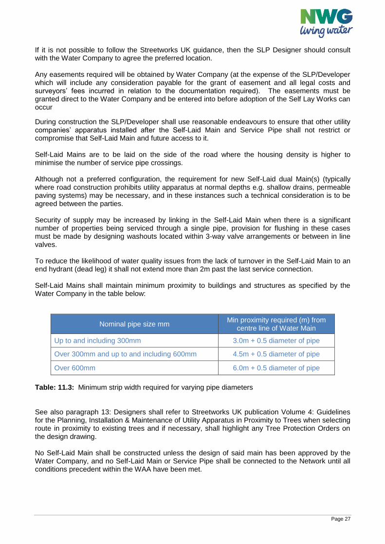
During construction the SLP/Developer shall use reasonable endeavours to ensure that other utility companies’ apparatus installed after the Self-Laid Main and Service Pipe shall not restrict or compromise that Self-Laid Main and future access to it. Self-Laid Mains are to be laid on the side of the road where the housing density is higher to minimise the number of service pipe crossings. Although not a preferred configuration, the requirement for new Self-Laid dual Main(s) (typically where road construction prohibits utility apparatus at normal depths e.g. shallow drains, permeable paving systems) may be necessary, and in these instances such a technical consideration is to be agreed between the parties. Security of supply may be increased by linking in the Self-Laid Main when there is a significant number of properties being serviced through a single pipe, provision for flushing in these cases must be made by designing washouts located within 3-way valve arrangements or between in line valves. To reduce the likelihood of water quality issues from the lack of turnover in the Self-Laid Main to an end hydrant (dead leg) it shall not extend more than 2m past the last service connection. Self-Laid Mains shall maintain minimum proximity to buildings and structures as specified by the Water Company in the table below:
Nominal pipe size mm Min proximity required (m) from
centre line of Water Main
Up to and including 300mm 3.0m + 0.5 diameter of pipe
Over 300mm and up to and including 600mm 4.5m + 0.5 diameter of pipe
Over 600mm 6.0m + 0.5 diameter of pipe
Table: 11.3: Minimum strip width required for varying pipe diameters See also paragraph 13: Designers shall refer to Streetworks UK publication Volume 4: Guidelines for the Planning, Installation & Maintenance of Utility Apparatus in Proximity to Trees when selecting route in proximity to existing trees and if necessary, shall highlight any Tree Protection Orders on the design drawing. No Self-Laid Main shall be constructed unless the design of said main has been approved by the Water Company, and no Self-Laid Main or Service Pipe shall be connected to the Network until all conditions precedent within the WAA have been met.
Page 28
11.4 Depth of Self-Laid Main Self-Laid Main(s) shall be installed at the appropriate cover depths in accordance with the minimum and maximum depth range specified in the Streetworks UK guidance relative to the surface in which the Self-Laid Main(s) are to be installed. The Water Company preferred installation depth (cover to crown of pipe) is be 900mm for new Self-Laid Mains.
11.5 Water quality considerations In accordance with the Principles of Water Supply Hygiene and related technical guidance notes listed therein (see Appendix 1-Other documents) the SLP shall ensure that the Developer and the SLP ensure demand is sufficient to allow adequate turnover of water following commissioning of any new Self-Laid Main in order to protect water quality. Where possible, Development spine roads shall be serviced with two-way fed ring mains to maintain water quality across the Site. The Water Company and SLP Designer shall consult on such proposals and the SLP Designer shall incorporate the Water Company requirements relative to this design consideration into the Site design. The costs associated with this shall be dealt with under the principles set out in paragraph 4 of this document. Where despite the above, infrastructure is laid in advance of turnover, the Self-Laid Main shall either have artificial load by way of cross connection into the live system or shall have a flushing programme denoted on the design, to be carried out by the SLP. The Developer or SLP shall be responsible for ensuring that all required permits and agreements are in place for identifying where water can be flushed to and for disposal of said water and whether water is required to be de-chlorinated prior to disposal.
Only standpipes that have been approved by the Water Company shall be used (details of such may be published on the Water Company website). Operation of valves: The Water Company’s specified standards in paragraph 11.7 below for operation of valves and hydrants shall be complied with (including satisfactory completion of any related training in line with guidance material offered by the Company).
Page 29
11.6 Mains fittings Valves, washouts, hydrants, etc. should, as far as is practicable be located in the footpath or verge for both access and safety reasons and to mitigate the effect of traffic, surface water and silting in chambers. Where there is no option but to design site fittings in trafficked areas, under no circumstances shall they be placed in parking bays or behind any locked access gates. Valves should be located:
At the junction of a branch main and its parent main
In order to isolate a maximum of 50 properties
Every 500m along a straight length of new main in the case where a 500m section of main
serves less than 50 properties.
Valves should be of the equivalent diameter to the main on which it is being installed.
A valve should be installed on a main immediately on the public highway side of any gated private
access roads.
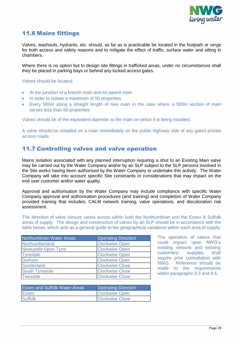
11.7 Controlling valves and valve operation Mains isolation associated with any planned interruption requiring a shut to an Existing Main valve may be carried out by the Water Company and/or by an SLP subject to the SLP persons involved in the Site works having been authorised by the Water Company to undertake this activity. The Water Company will take into account specific Site constraints or considerations that may impact on the end user customer and/or water quality. Approval and authorisation by the Water Company may include compliance with specific Water Company approval and authorisation procedures (and training) and completion of Water Company provided training that includes; CALM network training, valve operations, and discoloration risk assessment. The direction of valve closure varies across within both the Northumbrian and the Essex & Suffolk areas of supply. The design and construction of valves by an SLP should be in accordance with the table below, which acts as a general guide to the geographical variations within each area of supply:
Northumbrian Water Areas Operating Direction Northumberland Clockwise Open Newcastle Upon Tyne Clockwise Open Tynedale Clockwise Open Durham Clockwise Open Sunderland Clockwise Close South Tyneside Clockwise Close Teesside Clockwise Close Essex and Suffolk Water Areas Operating Direction Essex Clockwise Open Suffolk Clockwise Close
The operation of valves that could impact upon NWG’s existing network and existing customers’ supplies shall require prior consultation with NWG. Reference should be made to the requirements within paragraphs 9.3 and 9.5.
Page 30
11.8 Washout and fire hydrants Washouts are installed in order to maintain the integrity of water supply by providing flushing points. Combinations of isolation valves and washouts must be provided to enable the isolation and flushing of every section of main. Washouts and hydrants should, as far as is practicable be located in the footpath or verge for both access and safety reasons and to mitigate the effect of traffic, surface water and silting in chambers. Where there is no option but to design and install fittings in trafficked areas, under no circumstances shall they be placed in parking bays or behind any locked access gates. Washouts should be located:
At the end of every leg of main e.g. in a cul-de-sac
Where there is a change of diameter between two mains
Next to every closed district boundary valve, which NWG will identify and advise
Fire hydrants on water mains greater than 150mm diameter should be offset from the main and valve controlled. Fire hydrants shall be installed in accordance with the relevant Fire Authority’s location and specification requirements.
11.9 Air valves Air valves are required at high points and at points of significant changes of vertical direction along the network where in either case there is a risk of air locking. The location is to be agreed at design stage.
11.10 District metered areas and boundary valves District meter locations shall be agreed with the Water Company. If no information is available, then as a rule where the design exceeds 500 domestic properties in size or a development size of 500 properties then a DMA meter is likely to be required. See also paragraph 8.3. Shut valves will need to be installed if a Site is fed by two separate DMAs via two Source of Water Connections. In this instance their requirement and location shall be agreed at the design stage with the Water Company.
11.11 Sustainable drainage systems (SuDS) considerations SLP Designers shall ensure relative to the final installation of the Self-Laid Main and Service Pipe that any Sustainable Drainage System (SuDS) shall not be installed above, underneath, or adjacent to the final position of Self-Laid Mains and Service Pipe. The location of any proposed SuDS and permeable surfaces proposed for a Site are to be clearly marked on the proposed design drawing (see also paragraph 10.8).
Page 31
11.12 Double spade valves NWG does not require double spade valves to be used on Self Laid Mains.
11.13 Rights of access The Self-Laid Main shall, wherever possible, be routed in publicly adopted highways and maintained highways or streets as defined in NRSWA Section 48 (1) and amended under the Traffic Management Act (TMA) 2004. These shall not normally require rights of access. Examples of situations where Self-Laid Mains are to be laid in a street are:
An adopted street on land which is owned by a Local Authority.
A street on land which is owned by the Developer and which may or may not be adopted
in the future but serves more than one property.
A street on land which is in joint third-party ownership.
The section 38 Drawing shall be used to highlight any Self-Laid Main installed in third party land, which is not a street and that may require land rights to be obtained and a legal notice to be issued. In these instances, the Water Company shall establish and confirm with the Developer/SLP the right of access and shall normally require an easement to be provided by the land owner. Examples of situations where Self-Laid Mains are not to be laid in a street are:
Industrial and commercial Site where land is wholly owned by a singular 3rd Party.
Site access is through a third party’s land that does not form part of the development.
In cases requiring the Self-Laid Main to be laid in land not defined as a street all such permissions and rights of access shall be identified before the design is approved. In the process of designing it may be necessary to obtain other consents for works; these consents include:
Local Highways by way of Section 50 Agreements
Other Adopting Utilities where we are laying within an existing easement
Environmental Agencies and Waterways Authorities
Rail and Transport Network Operators
Historical Societies and National Heritage Agencies
All such servitudes, easements, wayleaves and planning permission required for the Self-Lay Works and land for the siting of equipment shall be obtained prior to commencement of works and in accordance with the Statutory Consents and Land Rights sections of the WAA. In accordance with the WAA, the Water Company shall obtain any required easements to protect its Network, or any future extension of such, and any related and/or incurred costs including third party costs shall be recovered by the Water Company in accordance with its published Charging Arrangements.
Page 32
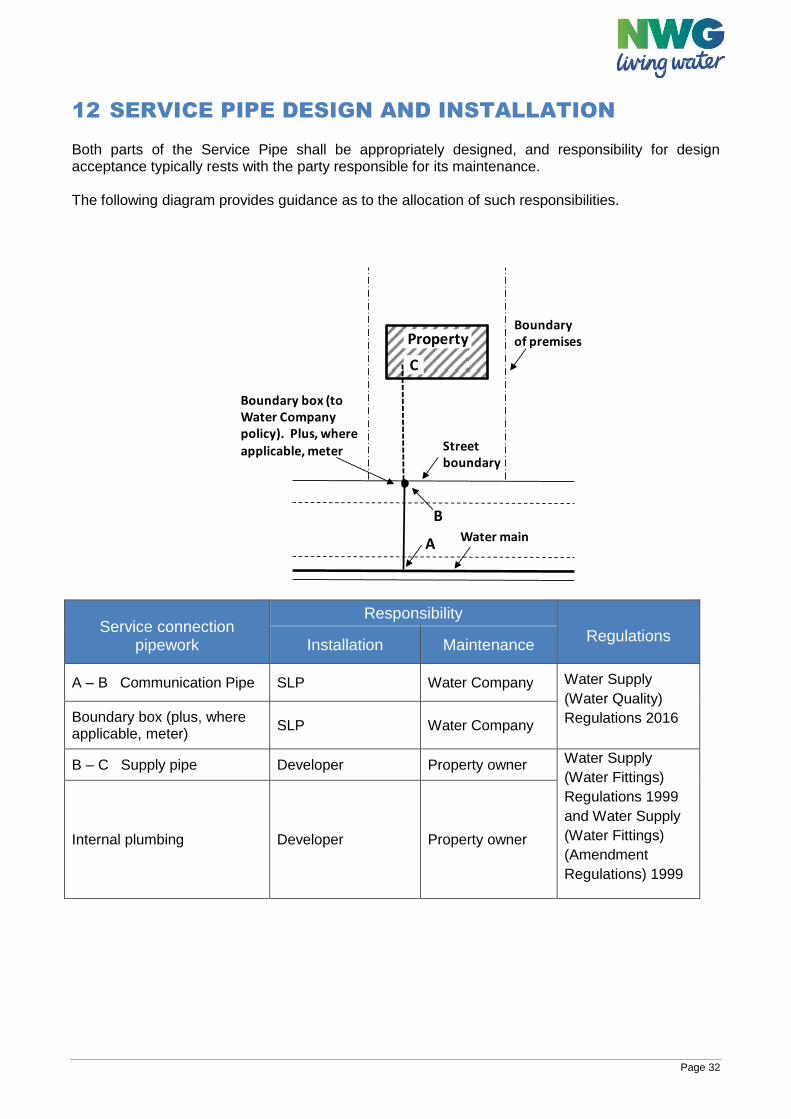
12 SERVICE PIPE DESIGN AND INSTALLATION Both parts of the Service Pipe shall be appropriately designed, and responsibility for design acceptance typically rests with the party responsible for its maintenance. The following diagram provides guidance as to the allocation of such responsibilities.
Service connection pipework
Responsibility
Regulations Installation Maintenance
A – B Communication Pipe SLP Water Company Water Supply
(Water Quality)
Regulations 2016 Boundary box (plus, where applicable, meter)
SLP Water Company
B – C Supply pipe Developer Property owner Water Supply
(Water Fittings)
Regulations 1999
and Water Supply
(Water Fittings)
(Amendment
Regulations) 1999
Internal plumbing Developer Property owner
Boundaryof premises
Street boundary
Water main
Boundary box (to Water Company policy). Plus, where
applicable, meter
A
B
Property
C
Page 33
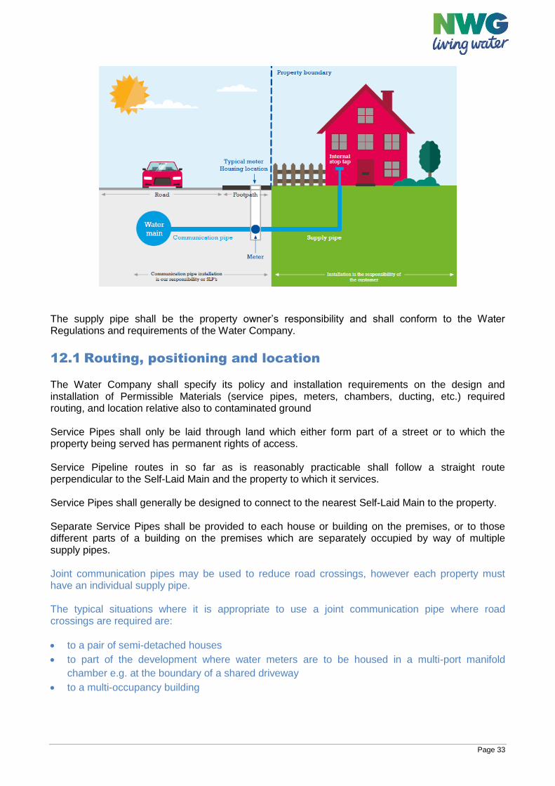
The supply pipe shall be the property owner’s responsibility and shall conform to the Water Regulations and requirements of the Water Company.
12.1 Routing, positioning and location The Water Company shall specify its policy and installation requirements on the design and installation of Permissible Materials (service pipes, meters, chambers, ducting, etc.) required routing, and location relative also to contaminated ground Service Pipes shall only be laid through land which either form part of a street or to which the property being served has permanent rights of access. Service Pipeline routes in so far as is reasonably practicable shall follow a straight route perpendicular to the Self-Laid Main and the property to which it services. Service Pipes shall generally be designed to connect to the nearest Self-Laid Main to the property. Separate Service Pipes shall be provided to each house or building on the premises, or to those different parts of a building on the premises which are separately occupied by way of multiple supply pipes. Joint communication pipes may be used to reduce road crossings, however each property must have an individual supply pipe. The typical situations where it is appropriate to use a joint communication pipe where road crossings are required are:
to a pair of semi-detached houses
to part of the development where water meters are to be housed in a multi-port manifold
chamber e.g. at the boundary of a shared driveway
to a multi-occupancy building
Page 34
The use of joint communication pipes is not appropriate where the routing of the associated branch communication pipes to each property would require some or all of them to be laid perpendicular to the joint communication pipe. To avoid the situation where multiple communication pipes cross the full width of a highway, it is an option to construct a length of main parallel to the curtilage of each new property. Each property shall then connect to the new main via an individual communication pipe. Service Pipes shall be designed such that the requirements of Streetworks UK are maintained with respect to separation from other plant and utilities.
12.2 Depth of services Service Pipes shall be installed in accordance with the Water Regulations and Streetworks UK guidance. Service pipes shall be laid with an even grade where possible, with cover between a depth of 750mm to 1350mm from the finished ground level in accordance with Water Supply (Water Fittings) Regulations 1999. If a boundary box is to be installed on the Service Pipe, the pipe shall be laid with cover between 750mm and 850mm for a minimum of 1.0 metre on each side of the boundary box. Service Pipes being designed outside this range shall have special protective measures vetted and agreed by the Approving Design Engineer.
12.3 Sizing of services While service connections can only be designed to meet minimum standards at the point of delivery every effort shall be made to ensure that all parts of the service pipe are sized in accordance with industry standards. Service Pipes shall be sized to ensure velocity is ≤2msˉ¹ and that total headloss is ≤5mH Services to standard domestic properties shall be minimum 25mm internal diameter and capable of supplying required flow and pressure based on required demand.
12.4 Location of boundary boxes NWG’s current meter location policy requires boundary boxes and multi-port manifold boxes to be located in the following order of preference:
Within the public footway, in what is, or will be, reinstated ground, avoiding vehicular access
points, as close as possible to the boundary of the property.
Within soft ground, as close as possible to the boundary of the property, within the public
footway
The boundary box or manifold chamber should be located in a position to avoid it being driven over by vehicles wherever possible e.g. entrances to driveways.
Page 35
12.5 Supplies to multi occupancy buildings Where it is practicable, each separately occupied building or part of a building should have its own communication pipe. However, this is often not a practical arrangement for multi-occupancy buildings and therefore it is acceptable to install joint communication pipes in such instances. Any joint communication pipe shall be branched (usually at the meter location) so that each property is supplied via a supply pipe that is independent to the supplies to other buildings or parts of a building in separate occupation.
12.6 Services to multi storey buildings Water Industry Act 1991 - Section 66 states that where the top-most storey in a building is greater than 10.5m below the draw off point the statutory undertaker may require the Developer to fit storage equal to twenty-four hours usage and adequate pumping to reach the highest point. Water supply installations within such buildings must comply with The Water Supply (Water Fittings) Regulations 1999. https://www.legislation.gov.uk/uksi/1999/1148/contents/made
12.7 Additional requirements for supplies to buildings other
than domestic dwellings When the Developer’s flow rates are in question the SLP Designer shall check that demand was calculated in accordance with BS EN 806. The design shall include for back flow prevention; at least single check non-return valves. Demand for process water shall be treated separately when designing the service. The SLP Designer shall investigate any seasonal demand patterns when designing the service.
Page 36
13 CIVIL ENGINEERING CONSIDERATIONS
13.1 General The general specification for civil engineering components and materials shall be that of the document “Civil Engineering Specification for The Water Industry (“CESWI”) 7th Edition which is available from the WRc plc. The Water Company shall confirm its requirements by reference to CESWI and any additional specific requirements and/or include such in the Schedule of Permissible Materials and Construction in paragraph 21, which as a minimum shall include information and requirements relating to:
Thrust Restraint and Anchorage
Puddle Flanges
Self-Anchoring Joints
Site Conditions and Ground Bearing Capacities
Thrust Blocks
Jointing of pipes
Ground Anchorage
13.2 Marker tape and tracer tape Marker Tape to be compliant with CESWI and Water Fittings Regulations.
13.3 Indicator posts and marker plates Indicator Posts and Marker Plates to be compliant with CESWI.
13.4 Chambers and covers Water Company to detail Permissible Materials in paragraph 21. Chambers shall be designed and installed to be of an appropriate size to allow operation of the Self-Laid Mains and service fittings. Covers shall be designed to be capable of withstanding all potential loads placed upon them and shall comply with BS EN 124.
13.5 Bedding and backfill Materials used for bedding shall conform to WIS 4-08-02 "Specification for bedding and side fill materials for buried pipelines” and material for backfill material shall be in accordance with the NRSWA 1919 the Specification for the Reinstatement of Opening in Highways (3rd Edition).
Page 37
13.6 Reinstatement of highway Materials and work shall be in accordance with the NRSWA 1991 the Specification for the Reinstatement of Opening in Highways (3rd Edition). The SLP is responsible for the classification and disposal of waste from excavations in highway accordance with Applicable Law.
13.7 Ducts SLP Designers shall consult with the Water Company at Design Acceptance stage if ducts are required to be installed by a SLP/Developer. Where ducts are designed to be laid under major roads or obstructions, they shall be shown to extend beyond the road to ease installation and future inspection. Service pipe ducting where extending into building to form part of the service entry must facilitate the installation of insulation to Water Fitting Regulations. Where ducts are used in relation to communication pipes, the ducting shall be compliant with Streetworks UK good practice guidance (Volumes 1 to 6). Where communication pipes are 32 mm in diameter or smaller, a maximum of two may be installed in a single duct. A separate duct shall be required for each communication pipe that is greater than 32 mm in diameter. The design and construction of Self Laid Mains in ducts should be avoided and will only be considered acceptable by NWG in exceptional circumstances, for example:
To facilitate future access where there is a highway crossing where damage by traffic loading is
a significant risk
Where the Self Laid Main crosses a major transport route and ducting will facilitate future
access, thus mitigating disruption to transport flow
Where the Self Laid Main crosses a body of water and the use of a ducting will facilitate future
access
Where ducts are used in relation to Self Laid Mains, i.e. only in appropriate and exceptional circumstances, the ducting is required to be compliant with Street Works UK Guidelines on the Positioning and Colour Coding of Underground Utilities’ Apparatus – Volumes 1 to 6.
14 METERING REQUIREMENTS
14.1 Standard domestic metering for individual dwellings and
multi occupancy buildings NWG’s domestic metering policy is included within paragraph 22 - Meter and Service Pipe Installation. Please refer to paragraph 19 for Local Practices relating to meter requirements. For information relating to the specification of meters and ancillary equipment, please refer to paragraph 21, Schedule of Permissible Materials and Construction.
Page 38
15 WATER FOR FIREFIGHTING
15.1 Fire and Rescue Service (FRS) consultation Pursuit to Section 43 (1) of the Fire and Rescue Services Act 2004 a plan showing adoptable washouts shall be sent to the FRS for consultation purposes, along with this plan shall be a location plan and a covering letter. Water Companies to provide FRS contact upon request from an SLP. The FRS have the statutory period, 42 calendar days, to respond with their requirements in respect of adopting hydrants for firefighting. Hydrants to be adopted shall be then marked on the drawing.
15.2 Location and flow from hydrants Ordinarily, water companies do not design distribution networks for firefighting purposes. It should be expected that flow from fire hydrants would be in line with minimum standards on the water distribution network.
See also Water UK Guidance: https://www.water.org.uk/guidance/national-guidance-document-on-the-provision-of-water-for-firefighting-3rd-edition-jan-2007/ (in particular those details referenced in Appendix 5 regards flow from fire hydrants)
15.3 Dedicated fire mains Dedicated fire mains shall be designed and constructed in accordance with Water Supply (Water Fittings) Regulations 2016 and fitted with backflow prevention, spiral wrapping and appropriate marker tape.
15.4 Fire sprinkler systems In the absence of any information from the Water Company, SLP Designers shall refer developers to the polices within the building regulations when requests for sprinklers are being made, these documents, “Document B (Fire Safety) –Volume 1: Dwellings and Volume 2: Buildings other than Dwelling houses”, can be obtained on the UK Government Planning Portal at http://www.planningportal.gov.uk/buildingregulations/ It is recommended that the SLP Designer consults with the Developer who is responsible for seeking advice from a specialist provider of sprinkler systems (where one is required) relative to the Site and/or Development. Additional information regarding NWG’s requirements for fire sprinkler systems is available in the document entitled “Water for firefighting systems” on our webpages https://www.nwl.co.uk/services/developers/water-services/water-connections/application-forms-and-guidance/ https://www.eswater.co.uk/services/developers/water-services/water-connections/application-forms-and-guidance/
Page 39
16 AS LAID (AS CONSTRUCTED) DRAWINGS The Water Company's asset data is typically recorded on a geographic information (digital mapping) or CAD systems. Therefore, it is important that accurate and compliant location information is supplied to the Water Company in a format agreed with the Water Company and which shall be specified by each Water Company in the Schedule of Permissible Materials and construction. The approved design drawing shall be updated and amended in accordance with all changes to as constructed installation whenever there is a deviation from the approved design (note: all changes to an approved design shall only be made with the acceptance of the Water Company as per Level of Service measure S2/1b). The “as-laid/as-constructed” installation shall be in accordance with the approved design and with any changes to same approved by the Water Company as any deviation not agreed by the Water Company from the approved design shall be a Defect and the Water Company may require such to be corrected prior to adoption of the installation. The position of all installed apparatus shall be recorded to ensure locational accuracy (the position of apparatus shall be recorded relative to a minimum of two fixed (geographical or otherwise) features adjacent to the installed apparatus and the measurements shall intersect the centre of the new asset and if available is to be referenced by British National grid reference). Positional accuracy is to be measured and recorded, wherever practicable, to a minimum GPS accuracy of +/- 100mm to the centre of the apparatus. Surveys for Self-Lay Works shall be carried out using triangulation, i.e., two measurements taken from fixed features. They should intersect at the centre of the asset in the following order of priority:
corners of buildings, and
corners of boundary walls
Surveys done using offsets, i.e. using a single measurement (usually along the length of the Self-Laid Main) in accordance with the following order of priority:
building lines, and
kerb lines
Temporary and natural features should only be used when no other permanent features are available, with the agreement of the Water Company. Scaled survey drawings should be provided. The scale shall be to 1:500 (unless otherwise agreed with the Water Company) to ensure clarity of applicable measurement and features. Material, pipe size, external and internal corrosion protection of pipe, and the depth of cover to Self-Laid Main (where depth differs from standard) shall be identified. All valves, hydrants, washouts, meters, ducts, swab access points, tappings, tees, Service Pipe(s) and boundary boxes shall be clearly identified, together with the relevant fitting on the plan and/or in an accompanying legend. The legend should be consistent with the Water Company' Schedule of Permissible Materials and construction.
Page 40
Where a number of assets are installed adjacent to each other, suitable asset information (increased scale extracts) are to be incorporated and clearly referenced as a subset of information from the Self-Laid Main “as-laid/as-constructed” drawing. The full dimensional references for all pipes and fittings shall be indicated (e.g. material, diameter, SDR) at any change in details, and measurements shall be in millimetres. Clear differentiation should be made between live and decommissioned Water Mains and associated fittings. Decommissioned Network assets may be shown on a separate drawing, if required. As-laid/as constructed drawings shall be submitted with any request to commission any completed work. Such shall be clearly labelled with the Developer's name, scheme number, scheme name, scheme type, stage, number, and date of submission.
17 SELF-LAID MAIN AND SERVICES COMMISSIONING To enable the commissioning of new assets to take place the Water Company shall provide its flushing, super chlorination and sampling requirements including minimum training requirements for samplers e.g. as per the Water Regulations under ISO/IEC 17025 may be deemed appropriate. A compliant pressure test should be carried out which demonstrates the Self-Laid Main to be free of air and leaks. Certificates shall be provided by the SLP to the Water Company confirming a compliant pressure test. Before flushing into a public combined or surface water sewer the developer shall contact and obtain approval from the local wastewater company, Environment Agency, Highway Authority or other, as appropriate. In addition, the Water Company may include further guidance in its Schedule of Permissible Materials and construction in paragraph 21.1 setting out its requirements for the provision of Testing and commissioning.
17.1 Mains flushing In accordance with the Principles of Water Supply Hygiene and associated technical guidance notes (see in particular TGN02 and TGN03) it is a requirement that there is always a sufficient turnover of water on all potential dead-legs of main or sectional lengths and a regular flushing of these mains shall be undertaken to satisfy water quality requirements. Accordingly, a suitable flushing regime is to be agreed in respect of the construction programme of the Self-Laid Main. The responsibility for work and related costs is set out in the WAA. Note: Operation of existing valves shall only be in accordance with the Water Company’s published guidelines in this DCS. The Water Company may seek to recover the cost of flushing work where a delay to the proposed Delivery Date occurs as a consequence of a failed pressure test and/or mains sample. This will likely delay the mains connection date and subsequent installation date of new service connections and hence an appropriate flushing regime to protect water quality will be required to be agreed with the Water Company who reserves the right to revert to a flushing regime operated and managed by the Water Company with costs recovered.
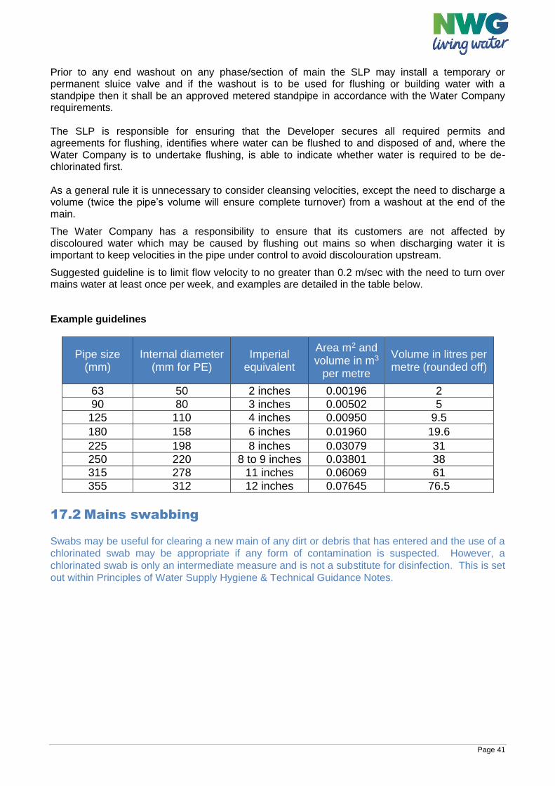
Page 41
Prior to any end washout on any phase/section of main the SLP may install a temporary or permanent sluice valve and if the washout is to be used for flushing or building water with a standpipe then it shall be an approved metered standpipe in accordance with the Water Company requirements. The SLP is responsible for ensuring that the Developer secures all required permits and agreements for flushing, identifies where water can be flushed to and disposed of and, where the Water Company is to undertake flushing, is able to indicate whether water is required to be de-chlorinated first. As a general rule it is unnecessary to consider cleansing velocities, except the need to discharge a volume (twice the pipe’s volume will ensure complete turnover) from a washout at the end of the main.
The Water Company has a responsibility to ensure that its customers are not affected by discoloured water which may be caused by flushing out mains so when discharging water it is important to keep velocities in the pipe under control to avoid discolouration upstream.
Suggested guideline is to limit flow velocity to no greater than 0.2 m/sec with the need to turn over mains water at least once per week, and examples are detailed in the table below.
Example guidelines
Pipe size (mm)
Internal diameter (mm for PE)
Imperial equivalent
Area m2 and volume in m3
per metre
Volume in litres per metre (rounded off)
63 50 2 inches 0.00196 2
90 80 3 inches 0.00502 5
125 110 4 inches 0.00950 9.5
180 158 6 inches 0.01960 19.6
225 198 8 inches 0.03079 31
250 220 8 to 9 inches 0.03801 38
315 278 11 inches 0.06069 61
355 312 12 inches 0.07645 76.5
17.2 Mains swabbing Swabs may be useful for clearing a new main of any dirt or debris that has entered and the use of a
chlorinated swab may be appropriate if any form of contamination is suspected. However, a
chlorinated swab is only an intermediate measure and is not a substitute for disinfection. This is set
out within Principles of Water Supply Hygiene & Technical Guidance Notes.
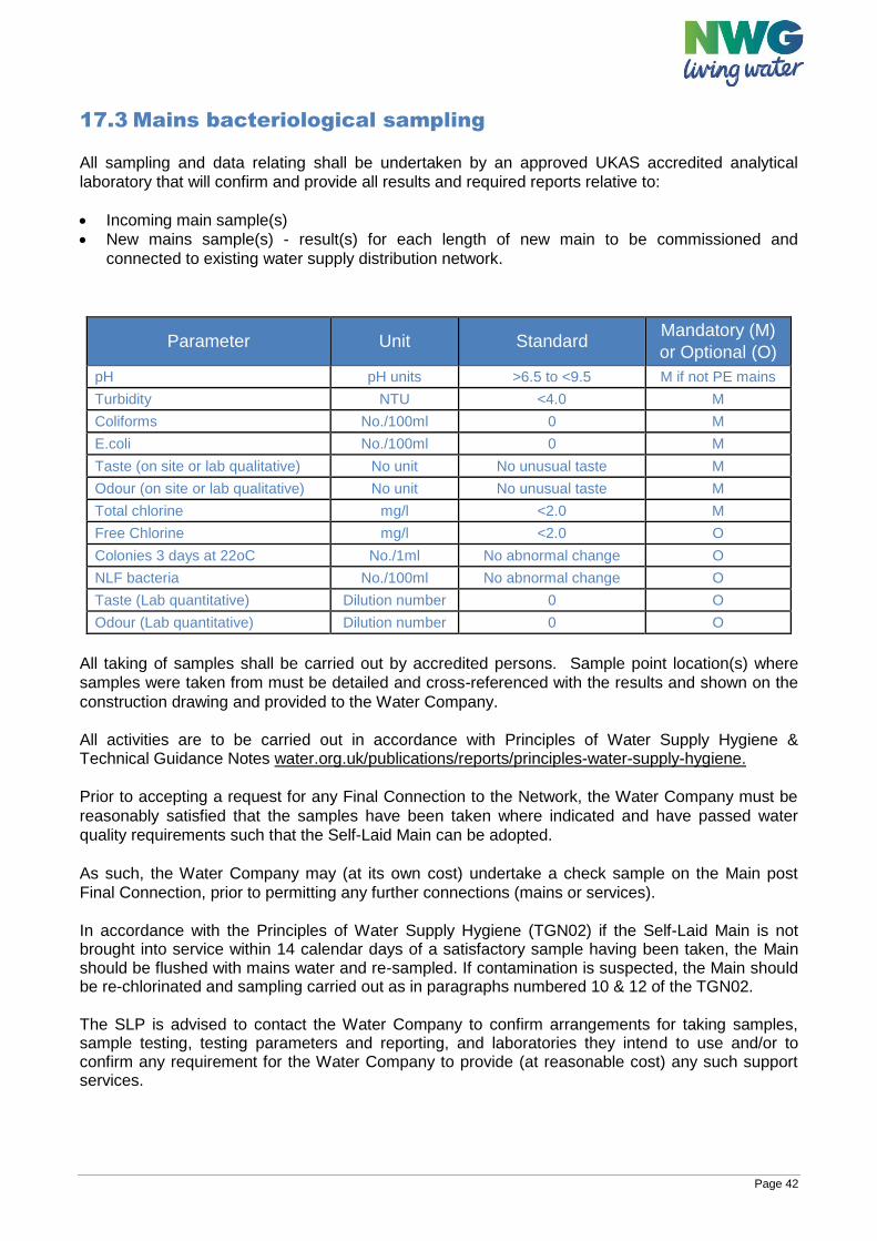
Page 42
17.3 Mains bacteriological sampling
All sampling and data relating shall be undertaken by an approved UKAS accredited analytical
laboratory that will confirm and provide all results and required reports relative to:
Incoming main sample(s)
New mains sample(s) - result(s) for each length of new main to be commissioned and
connected to existing water supply distribution network.
Parameter Unit Standard Mandatory (M)
or Optional (O)
pH pH units >6.5 to <9.5 M if not PE mains
Turbidity NTU <4.0 M
Coliforms No./100ml 0 M
E.coli No./100ml 0 M
Taste (on site or lab qualitative) No unit No unusual taste M
Odour (on site or lab qualitative) No unit No unusual taste M
Total chlorine mg/l <2.0 M
Free Chlorine mg/l <2.0 O
Colonies 3 days at 22oC No./1ml No abnormal change O
NLF bacteria No./100ml No abnormal change O
Taste (Lab quantitative) Dilution number 0 O
Odour (Lab quantitative) Dilution number 0 O
All taking of samples shall be carried out by accredited persons. Sample point location(s) where
samples were taken from must be detailed and cross-referenced with the results and shown on the
construction drawing and provided to the Water Company.
All activities are to be carried out in accordance with Principles of Water Supply Hygiene & Technical Guidance Notes water.org.uk/publications/reports/principles-water-supply-hygiene.
Prior to accepting a request for any Final Connection to the Network, the Water Company must be
reasonably satisfied that the samples have been taken where indicated and have passed water
quality requirements such that the Self-Laid Main can be adopted.
As such, the Water Company may (at its own cost) undertake a check sample on the Main post
Final Connection, prior to permitting any further connections (mains or services).
In accordance with the Principles of Water Supply Hygiene (TGN02) if the Self-Laid Main is not brought into service within 14 calendar days of a satisfactory sample having been taken, the Main should be flushed with mains water and re-sampled. If contamination is suspected, the Main should be re-chlorinated and sampling carried out as in paragraphs numbered 10 & 12 of the TGN02. The SLP is advised to contact the Water Company to confirm arrangements for taking samples, sample testing, testing parameters and reporting, and laboratories they intend to use and/or to confirm any requirement for the Water Company to provide (at reasonable cost) any such support services.
Page 43
17.4 Pressure testing of Self-Laid Main
17.4.1 Pressure testing of pressure pipes and fittings for use by public water suppliers must be carried out as set out in the Water Industry ‘Information and Guidance note’ (IGN 4-01-03 October 2015: issue 2), available to view online at water.org.uk/publications/wis-ign/general with reference to the following guidance notes: ‘Pressure Testing and Disinfection (supplemental) of PE Water Pipelines, Services and Installations’. Pressure data, analysis report/pass certificate and pressurisation/decay graphs are to be provided by the SLP to the Water Company within a handover commissioning suite of information.
All results must be provided in both graphical (test output graph) and tabular formats.
17.4.2 Pressure Testing and Disinfection (supplemental) of PE Water Pipelines, Services and Installations
All testing shall be carried out in accordance with IGN 4-01-03, reference should also be made to the Civil Engineering Specification for the Water Industry (CESWI) (with Additional Clauses) and any specific Water Company requirements specified additionally in paragraph 21 Schedule of Permissible Materials and construction.
The following also applies: 1. On-site testing operations will be clearly identified using appropriate warning notice
boards.
2. Service test: All new Service Pipe connections must undergo a service test. The
procedure is also defined in Water Industry Information & Guidance Note (IGN 4-01-
03) ‘Pressure Testing of Pressure Pipes and Fittings for use by Public Water
Suppliers’.
The system test pressure shall be 18 bar.
The service shall not have been tapped prior to this test being conducted.
18 WATER COMPANY KEY CONTACTS Key contacts will be available on NWG websites.
Page 44
19 LOCAL PRACTICES By reference to the Water Sector Guidance, the Water Company may insert here a permitted local practice using the terminology in the WSG.
19.1 Meter pairing and commissioning Local practice not applicable for NWG
19.2 Timing of the generation of plot reference numbers Pre connection:
At the quotation stage NWG requires plot references to be displayed on the AutoCAD/site layout
drawing. That is, each house or non-household premise is required to be have its own unique
reference such as a plot number. Where a development includes blocks of flats NWG requires
unique references per flat on the drawing.
Post connection:
Where self-laid service connections are installed, NWG requires information to enable it to change
the plot references of each connected property into its new postal address. The postal address
information, confirmed by the local authority, for each new property shall be supplied by the SLP.
Once a service connection has been made by an SLP, they shall provide the postal address for the
newly connected property to NWG, as appropriate. The required timescale for providing this
information shall be within 5 calendar days for household properties and 1 working day for non-
household properties. If an SLP installs meters, NWG shall require the meter details (such as meter
serial number) within the aforementioned timescales.
If NWG is requested to install the meters to self-laid service connections, this activity will take place
once the postal address information has been received.
19.3 Water company design service offerings Local practice not applicable for NWG
19.4 Design self-certification scheme Local practice not applicable for NWG
20 DESIGN AND CONSTRUCTION SPECIFICATION
APPENDICES Page 64 APPENDIX 1 –Water Industry Specifications and Information & Guidance Notes Page 65 APPENDIX 2 - British Standards (BS) & BS EN Standards Page 66 APPENDIX 3 - Other Documents
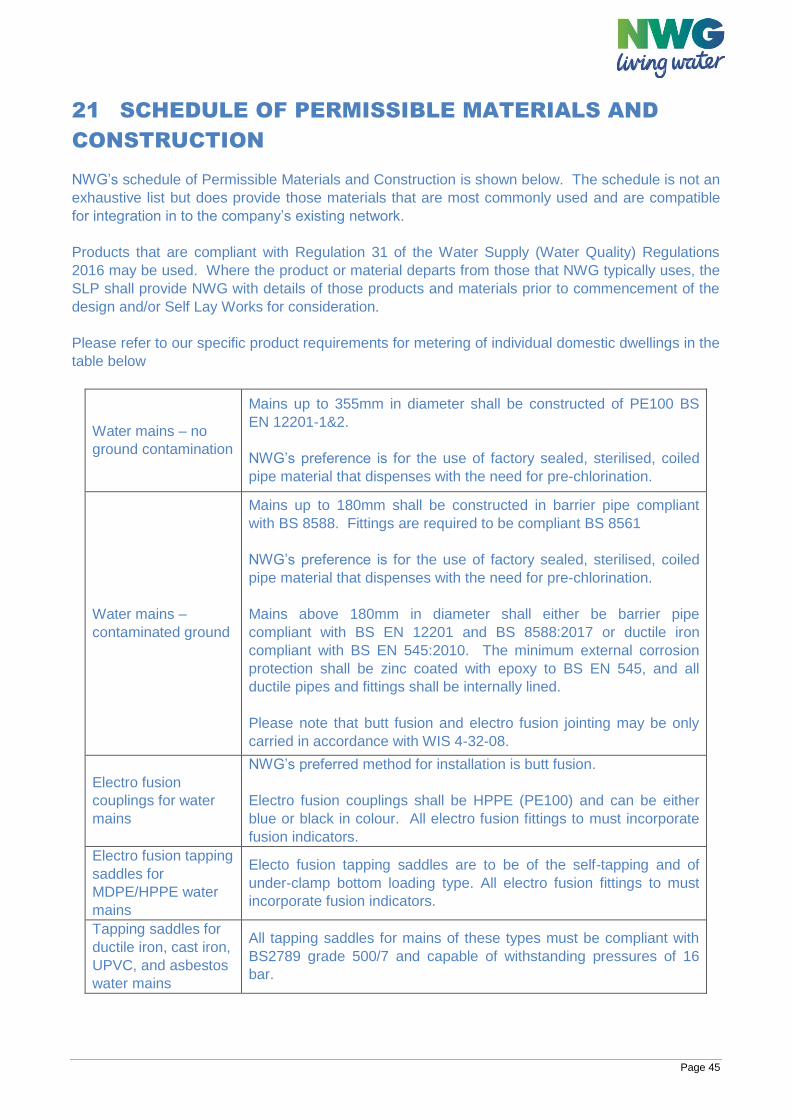
Page 45
21 SCHEDULE OF PERMISSIBLE MATERIALS AND
CONSTRUCTION NWG’s schedule of Permissible Materials and Construction is shown below. The schedule is not an
exhaustive list but does provide those materials that are most commonly used and are compatible
for integration in to the company’s existing network.
Products that are compliant with Regulation 31 of the Water Supply (Water Quality) Regulations
2016 may be used. Where the product or material departs from those that NWG typically uses, the
SLP shall provide NWG with details of those products and materials prior to commencement of the
design and/or Self Lay Works for consideration.
Please refer to our specific product requirements for metering of individual domestic dwellings in the
table below
Water mains – no
ground contamination
Mains up to 355mm in diameter shall be constructed of PE100 BS
EN 12201-1&2.
NWG’s preference is for the use of factory sealed, sterilised, coiled
pipe material that dispenses with the need for pre-chlorination.
Water mains –
contaminated ground
Mains up to 180mm shall be constructed in barrier pipe compliant
with BS 8588. Fittings are required to be compliant BS 8561
NWG’s preference is for the use of factory sealed, sterilised, coiled
pipe material that dispenses with the need for pre-chlorination.
Mains above 180mm in diameter shall either be barrier pipe
compliant with BS EN 12201 and BS 8588:2017 or ductile iron
compliant with BS EN 545:2010. The minimum external corrosion
protection shall be zinc coated with epoxy to BS EN 545, and all
ductile pipes and fittings shall be internally lined.
Please note that butt fusion and electro fusion jointing may be only
carried in accordance with WIS 4-32-08.
Electro fusion
couplings for water
mains
NWG’s preferred method for installation is butt fusion.
Electro fusion couplings shall be HPPE (PE100) and can be either
blue or black in colour. All electro fusion fittings to must incorporate
fusion indicators.
Electro fusion tapping
saddles for
MDPE/HPPE water
mains
Electo fusion tapping saddles are to be of the self-tapping and of
under-clamp bottom loading type. All electro fusion fittings to must
incorporate fusion indicators.
Tapping saddles for
ductile iron, cast iron,
UPVC, and asbestos
water mains
All tapping saddles for mains of these types must be compliant with
BS2789 grade 500/7 and capable of withstanding pressures of 16
bar.
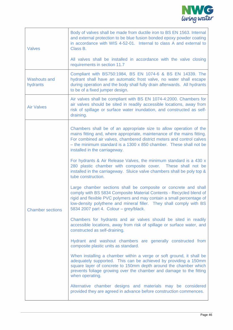
Page 46
Valves
Body of valves shall be made from ductile iron to BS EN 1563. Internal
and external protection to be blue fusion bonded epoxy powder coating
in accordance with WIS 4-52-01. Internal to class A and external to
Class B.
All valves shall be installed in accordance with the valve closing
requirements in section 11.7
Washouts and
hydrants
Compliant with BS750:1984, BS EN 1074-6 & BS EN 14339. The
hydrant shall have an automatic frost valve, no water shall escape
during operation and the body shall fully drain afterwards. All hydrants
to be of a fixed jumper design.
Air Valves
Air valves shall be compliant with BS EN 1074-4:2000. Chambers for
air valves should be sited in readily accessible locations, away from
risk of spillage or surface water inundation, and constructed as self-
draining.
Chamber sections
Chambers shall be of an appropriate size to allow operation of the
mains fitting and, where appropriate, maintenance of the mains fitting.
For combined air valves, chambered district meters and control calves
– the minimum standard is a 1300 x 850 chamber. These shall not be
installed in the carriageway.
For hydrants & Air Release Valves, the minimum standard is a 430 x
280 plastic chamber with composite cover. These shall not be
installed in the carriageway. Sluice valve chambers shall be poly top &
tube construction.
Large chamber sections shall be composite or concrete and shall
comply with BS 5834 Composite Material Contents - Recycled blend of
rigid and flexible PVC polymers and may contain a small percentage of
low-density polythene and mineral filler. They shall comply with BS
5834 2007 part 4. Colour – grey/black.
Chambers for hydrants and air valves should be sited in readily
accessible locations, away from risk of spillage or surface water, and
constructed as self-draining.
Hydrant and washout chambers are generally constructed from composite plastic units as standard. When installing a chamber within a verge or soft ground, it shall be adequately supported. This can be achieved by providing a 150mm square layer of concrete to 150mm depth around the chamber which prevents foliage growing over the chamber and damage to the fitting when operating.
Alternative chamber designs and materials may be considered
provided they are agreed in advance before construction commences.
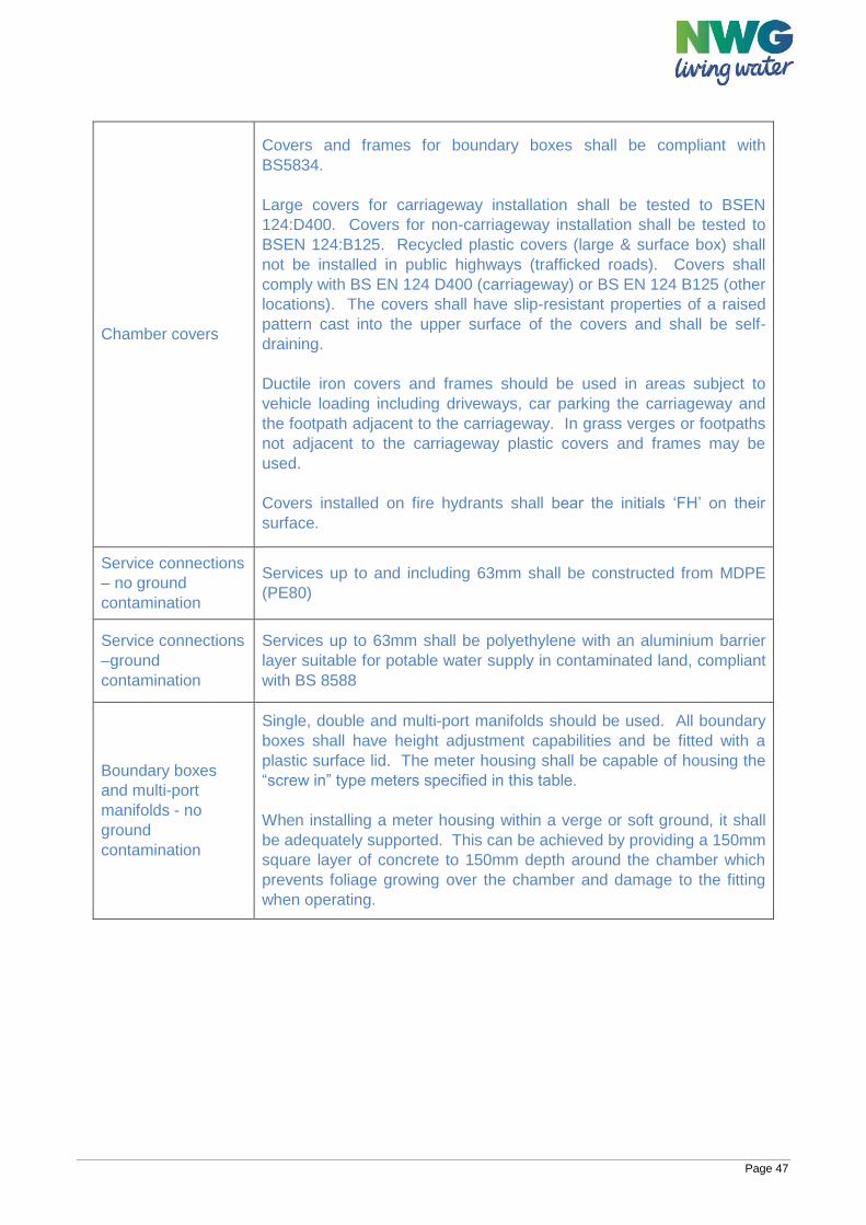
Page 47
Chamber covers
Covers and frames for boundary boxes shall be compliant with
BS5834.
Large covers for carriageway installation shall be tested to BSEN
124:D400. Covers for non-carriageway installation shall be tested to
BSEN 124:B125. Recycled plastic covers (large & surface box) shall
not be installed in public highways (trafficked roads). Covers shall
comply with BS EN 124 D400 (carriageway) or BS EN 124 B125 (other
locations). The covers shall have slip-resistant properties of a raised
pattern cast into the upper surface of the covers and shall be self-
draining.
Ductile iron covers and frames should be used in areas subject to
vehicle loading including driveways, car parking the carriageway and
the footpath adjacent to the carriageway. In grass verges or footpaths
not adjacent to the carriageway plastic covers and frames may be
used.
Covers installed on fire hydrants shall bear the initials ‘FH’ on their
surface.
Service connections
– no ground
contamination
Services up to and including 63mm shall be constructed from MDPE
(PE80)
Service connections
–ground
contamination
Services up to 63mm shall be polyethylene with an aluminium barrier
layer suitable for potable water supply in contaminated land, compliant
with BS 8588
Boundary boxes
and multi-port
manifolds - no
ground
contamination
Single, double and multi-port manifolds should be used. All boundary
boxes shall have height adjustment capabilities and be fitted with a
plastic surface lid. The meter housing shall be capable of housing the
“screw in” type meters specified in this table.
When installing a meter housing within a verge or soft ground, it shall
be adequately supported. This can be achieved by providing a 150mm
square layer of concrete to 150mm depth around the chamber which
prevents foliage growing over the chamber and damage to the fitting
when operating.
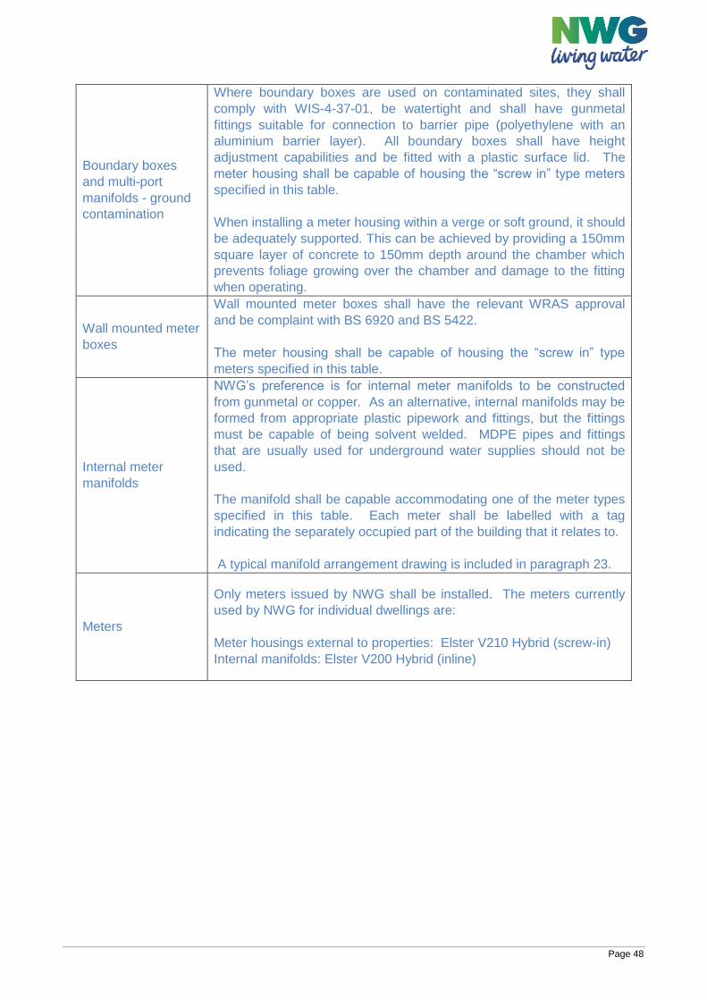
Page 48
Boundary boxes
and multi-port
manifolds - ground
contamination
Where boundary boxes are used on contaminated sites, they shall
comply with WIS-4-37-01, be watertight and shall have gunmetal
fittings suitable for connection to barrier pipe (polyethylene with an
aluminium barrier layer). All boundary boxes shall have height
adjustment capabilities and be fitted with a plastic surface lid. The
meter housing shall be capable of housing the “screw in” type meters
specified in this table.
When installing a meter housing within a verge or soft ground, it should
be adequately supported. This can be achieved by providing a 150mm
square layer of concrete to 150mm depth around the chamber which
prevents foliage growing over the chamber and damage to the fitting
when operating.
Wall mounted meter
boxes
Wall mounted meter boxes shall have the relevant WRAS approval
and be complaint with BS 6920 and BS 5422.
The meter housing shall be capable of housing the “screw in” type
meters specified in this table.
Internal meter
manifolds
NWG’s preference is for internal meter manifolds to be constructed
from gunmetal or copper. As an alternative, internal manifolds may be
formed from appropriate plastic pipework and fittings, but the fittings
must be capable of being solvent welded. MDPE pipes and fittings
that are usually used for underground water supplies should not be
used.
The manifold shall be capable accommodating one of the meter types
specified in this table. Each meter shall be labelled with a tag
indicating the separately occupied part of the building that it relates to.
A typical manifold arrangement drawing is included in paragraph 23.
Meters
Only meters issued by NWG shall be installed. The meters currently
used by NWG for individual dwellings are:
Meter housings external to properties: Elster V210 Hybrid (screw-in)
Internal manifolds: Elster V200 Hybrid (inline)
Page 49
Pipe Jointing
Pipe jointing activity shall comply with CESWI clause 5.7 & 5.8 Pipe Jointing.
The layout of pipe systems should be designed to minimise the number of joints required. Factory
sealed coiled pipes are preferred for mains installation as they negate the requirement for pre-
chlorination. Mains can be laid with up to 50m coils up to 125mm diameter. If the use of coiled pipe
is not possible, NWG’s next preference is for the use of 6m sticks.
NWG’s preferred method of jointing plastic pipes is using the butt fusion method. Pipes shall be of
identical diameter and pressure ratings and bear the relevant BS. Electrofusion is NWG’s next
preference and then mechanical jointing methods. Where mechanical jointing is proposed, this
should be subject to agreement with NWG in advance.
Thrust Blocks, Restraint and Anchorage Thrust Blocks, Thrust Restraint and Anchorage, Self-Anchoring Joints, and Ground Anchorage shall comply with CESWI clause 5.6 Thrust Blocks. Thrust block design shall be carried out in accordance with CIRIA R128 - Guide to the Design of Thrust Blocks for Buried Pressure Pipelines.
Puddle Flanges
Exact details, materials and installation methods proposed are to be confirmed with NWG.
Site Conditions
Pipes and fittings should be transported and carefully stored on site, off the ground, to avoid entry of
dirt or vermin. All pipes should be supplied with close-fitting end caps where feasible and these
should remain in place until the pipe is laid. All pipes and fittings (and in particular plastic types)
should be kept clear of fuel oils, and any materials so contaminated should be discarded.
All fittings and pipe ends should be free of any visible contamination and sprayed with a solution of
1000mg/l free available chlorine as they are laid.
Care should be taken to prevent water, subsoil or other material entering a pipeline under
construction. It should not be assumed that such material will be flushed out on commissioning.
Additional cleaning measures (e.g. swabbing) and inspection techniques (e.g. CCTV) should be
considered prior to commissioning on larger diameter mains.
Ground Bearing Capacities
Exact details, materials and installation methods proposed are to be confirmed with NWG.
Page 50
22 METER AND SERVICE PIPE POLICY
AND INSTALLATION
22.1 Service pipes NWG’s requirements in relation of service pipes are included within section 12 of this document.
22.2 Metering - general requirements Where new buildings or parts of buildings are capable of separate occupation, each building or part of a building under separate occupation shall require its own water meter. Wherever practicable meters should be located external to buildings to allow for ease of access for reading and maintenance.
22.3 Metering of individual dwellings NWG requires meters to be housed in boundary boxes or multi-port manifold chambers (where appropriate) external to the building in accordance with the location preferences indicated below:
Within the public footway, in what is, or will be, reinstated ground, avoiding vehicular access points (such as driveways), as close as possible to the boundary of the property.
Within soft ground, as close as possible to the boundary of the property within the public footway In the event that the boundary box is to be located in soft ground, the cover should be set within a suitable concrete surround set flush with the final permanent surface in which the chamber is to be located in. See paragraph 21 for details. Where a single meter is required, it shall be installed in an appropriate boundary box that includes an integral meter carrier and stop-tap. Where multiple meters are to be installed, the preference is to house them, where practicable, in a multi manifold chamber of typically two, for and six meter ports. Meter chambers, covers and frames shall be suitable for the final surface, ground conditions, and location in which they are to be installed. All boundary boxes and meter manifold chambers shall be installed to the manufacturer’s installation instructions and capable of housing the meters indicated in paragraph 21. External wall mounted boxes may be used to house single meters as an alternative to a boundary box. Developers or SLPs shall be responsible for the procurement of the boxes from the manufacturer or their distributors. The boxes shall be fixed to the front elevation of a house/building, so they are accessible at all times for maintenance and operational requirements. On a new development site, the SLP/developer shall lay an unjointed service pipe from the wall box to the water main, including through any ducts, if the main is the opposite side of a highway. All wall boxes shall be installed to the manufacturer’s installation instructions and capable of housing meters indicated in paragraph 21.
Page 51
22.4 Metering of multi-occupancy buildings Where it is practicable, meters for multi-occupancy buildings shall be located in multi-port manifold boxes external to the building in accordance with the location preferences indicated in paragraph 22.3 above. There will be circumstances where locating meters externally to a building is not possible or practical. In such circumstances, internal meters may be used. Internal meters shall be installed on a suitable manifold arrangement (see paragraph 23 for details) and located where they can be easily accessed to be read, maintained or exchanged. Access to the meters for both NWG staff and customers is required at all times. Internal meter manifold arrangements are typically installed in purpose built plant or maintenance rooms or riser cupboards. Meters shall not be sited in any roof space or installed in a position that exceeds 1.5 metres from the ground in the room that they are installed. Where meters are installed internally, the meter shall be of the type that can be read remotely and therefore will include an Automatic Meter Reading (AMR) device (see paragraph 21 for meter types).
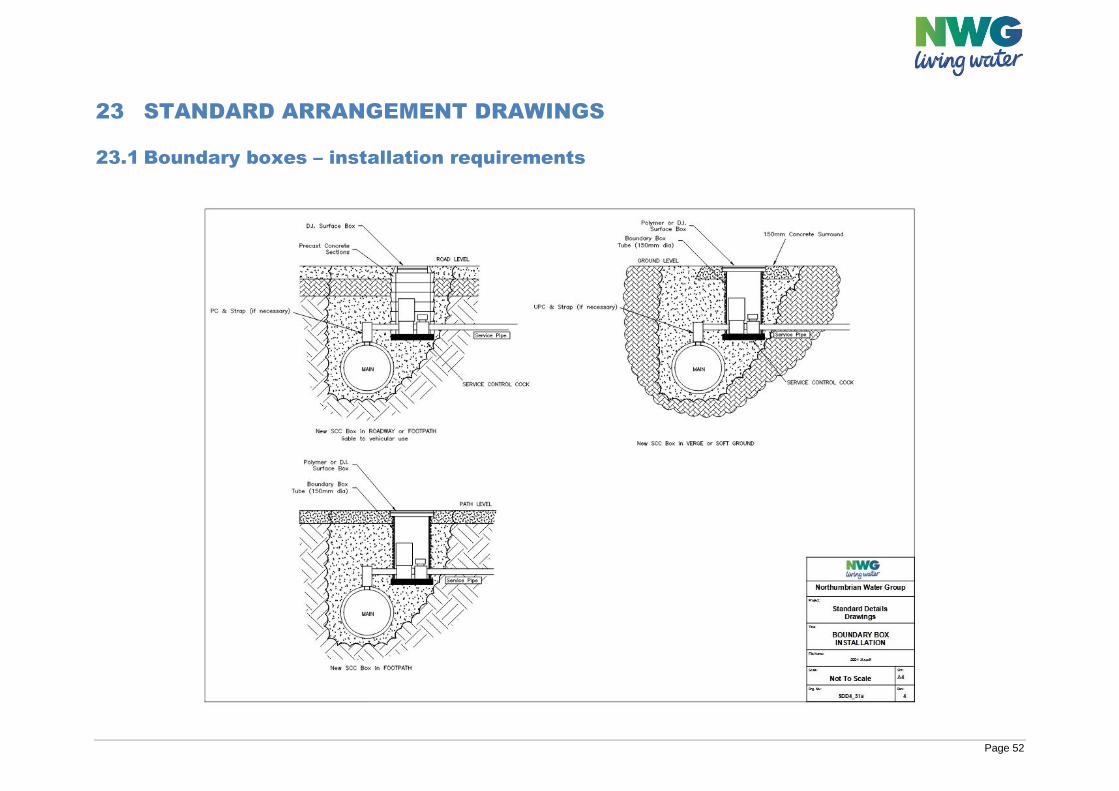
Page 52
23 STANDARD ARRANGEMENT DRAWINGS
23.1 Boundary boxes – installation requirements
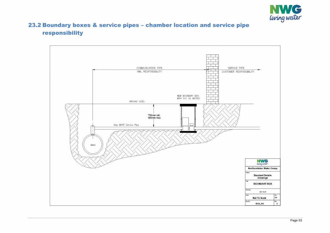
Page 53
23.2 Boundary boxes & service pipes – chamber location and service pipe
responsibility
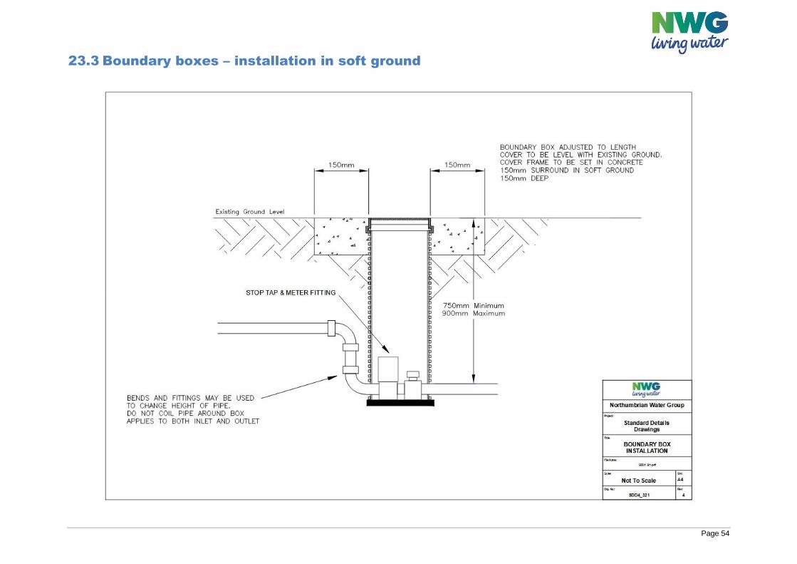
Page 54
23.3 Boundary boxes – installation in soft ground
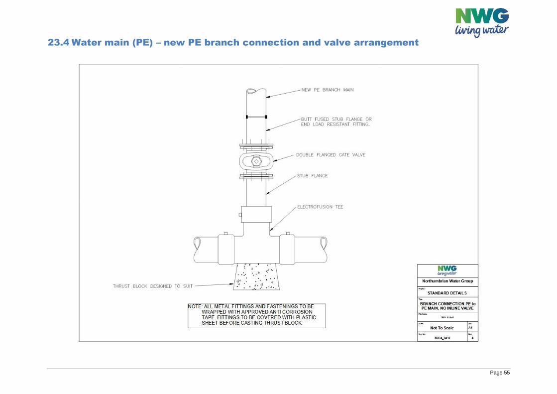
Page 55
23.4 Water main (PE) – new PE branch connection and valve arrangement
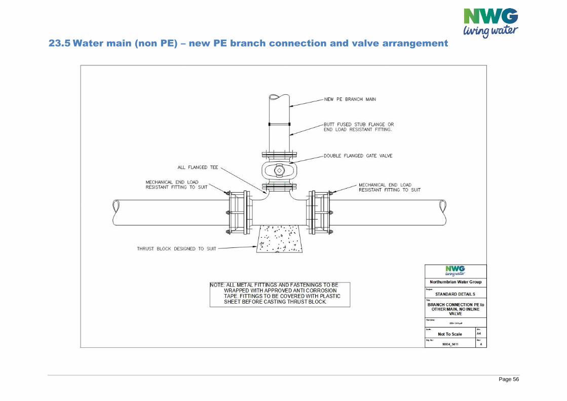
Page 56
23.5 Water main (non PE) – new PE branch connection and valve arrangement
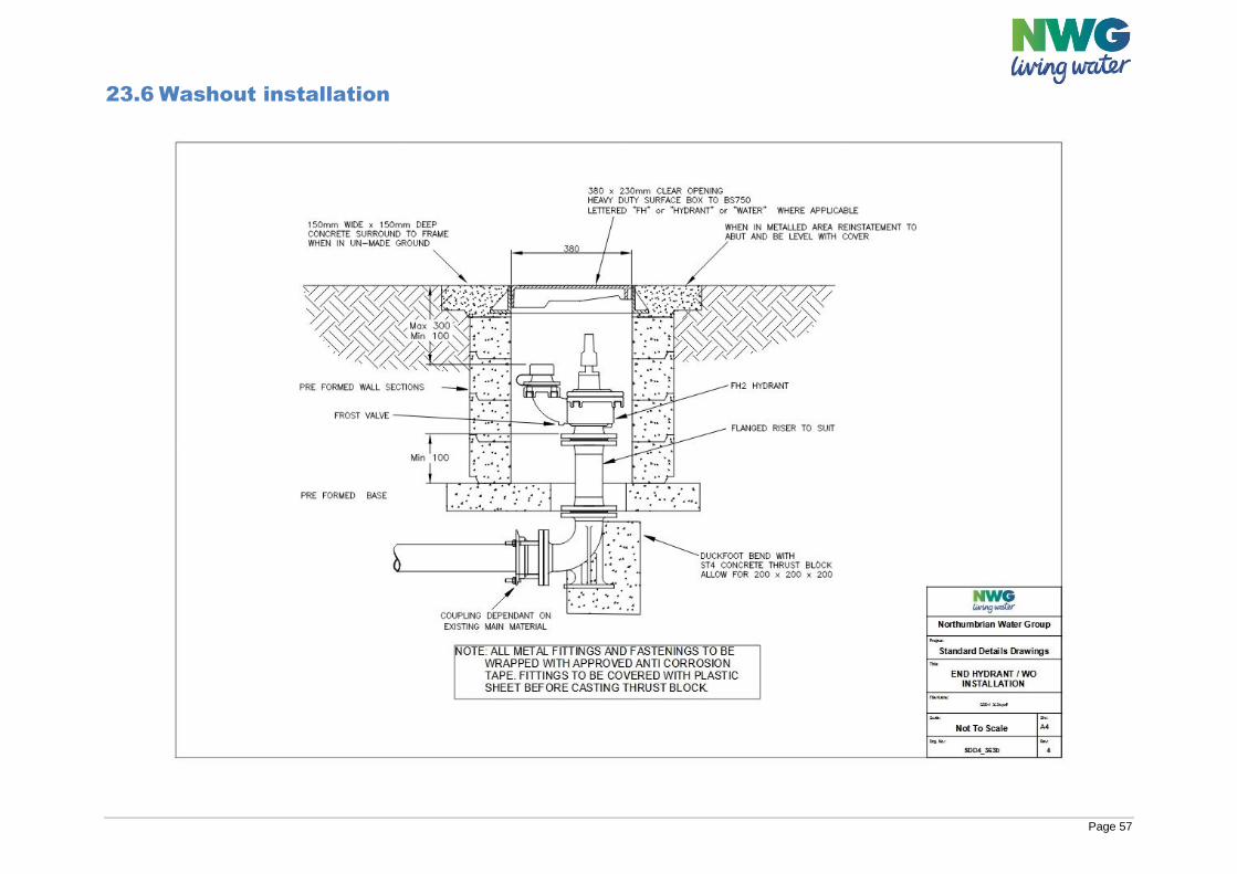
Page 57
23.6 Washout installation
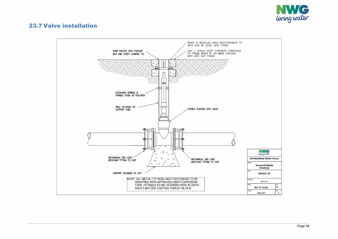
Page 58
23.7 Valve installation
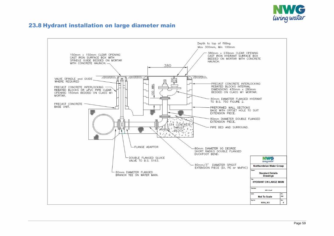
Page 59
23.8 Hydrant installation on large diameter main
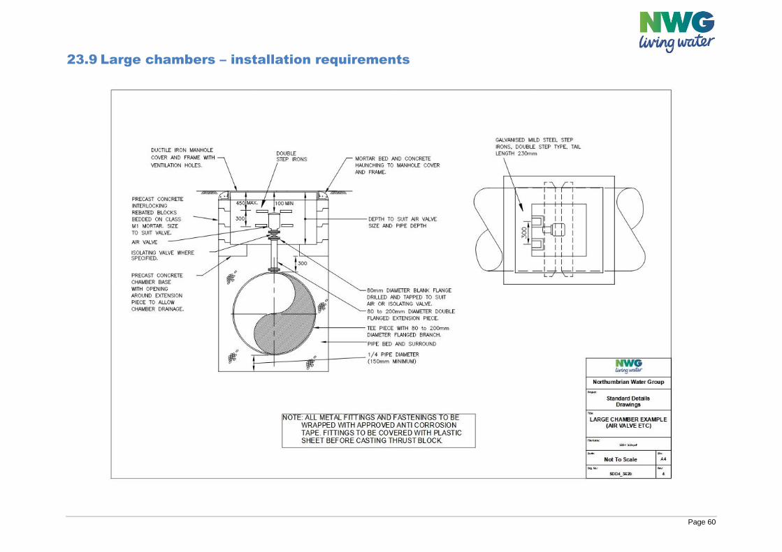
Page 60
23.9 Large chambers – installation requirements
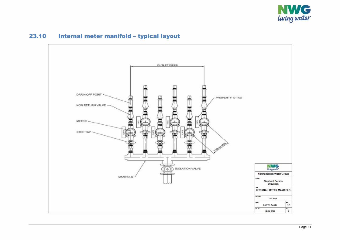
Page 61
23.10 Internal meter manifold – typical layout
Page 62
24 CONSTRUCTION PRE-START MEETING AGENDA
A pre-start meeting shall only be required if one party to the WAA submits a written request to the remaining Parties notifying them that it requires a pre-start meeting. However, such meetings are viewed by Water Companies as a key means of helping to achieve good Health and Safety outcomes, of securing timely, cost-effective delivery and ensuring smooth adoption and handover. For this reason, they will generally be requested by Water Companies. In more detail, such meetings will allow the following aspects of the project to be addressed:
Site-specific Health & Safety and site management issues
Confirmation of the identity of the Principal Contractor under CDM Regulations
Introduce site personnel and establish their individual roles and responsibilities
Establish local lines of communication between site and Water Company staff
Assess any associated construction activity that may need accommodating in the SLP
construction programme
Discuss issues relating to the distribution that have the potential to affect the project.
The Parties shall agree the date of the pre-start meeting and shall record the minutes of the meeting and circulate such within 5 calendar days. The pre-start meeting shall include the ‘pre-start information’ listed below.
Where no pre-start meeting is required by a party, the SLP and/or Developer shall, if requested by the Water Company, prior to the commencement of the Self-Lay Works, provide the following pre-start information in any event.
‘Pre-start information’ includes as a minimum:
1. Confirmed arrangements for CDM 2015 Regulations and other H&S requirements.
2. Future contact arrangements and authorised parties for giving instructions, agreeing “right day” for SLAs, making variations, and exchanging information regarding progress with all parties’ works.
3. Confirmation of line and level of Self-lay Works.
4. Confirmation of national (Street-Works) and local (Water Company) design requirements.
5. Overview of process for dealing with variations/ and changes to the Site layout and associated approved design drawing (revisions and impact on design, co-ordination and charges etc.).
6. Confirm and detail the Source of Water for testing and mains connection Delivery Date.
7. Confirm latest design approved drawing, and any revision, and drawing for construction
8. Process for submitting as-laid drawings.
Page 63
9. Identify any potential site hazards or constraints (such as existing Network considerations, including protection, diversion or renewal)
10. Confirm that access is approved relative to any land rights, statute, and third-party consents.
11. Contact details.
12. An indication of when any new service connections are required by and if any new property is to be fed from the Network.
13. Confirmation that the Agreement has been signed by all Parties.
14. Completion and issue by the SLP and/or Developer and/or the Water Company of all risk and method statements relative to design and/or construction activities.
15. Arrangements for co-ordination of activities.
16. Arrangements for supply of proof of WIRS Accreditation, personnel qualifications and/or certification documents (i.e. Hygiene Code of Practice).
17. Arrangements for water sampling and requirements for certification and accreditation of results, pressure testing, and disposal of water.
18. Arrangements for Water Company approved standpipe supply if required.
19. Confirmation of all required Regulatory requirements, arrangements, permits and consents relative to the construction, flushing (and any future arrangements to maintain water quality), and commissioning of the Self-lay Works.
20. Confirmation of any requirement for a Water Company post commissioning check sample by the Water Company in accordance with the Code Procedures.
21. Arrangements and contact details for future management of Defects and/or damage following adoption.
22. Confirmation of how the SLP proposes to demonstrate to the Water Company that the materials and products intending to be used (and on completion of work all actual materials used in case of divergence from the intended list) in the installation of Self-lay Works complies with Regulation 31 of The Water Supply (Water Quality) Regulations 2016 before commencement of any work. This confirmation may consist of the SLP providing the Regulation 31 appropriate identifier relative to the materials proposed.
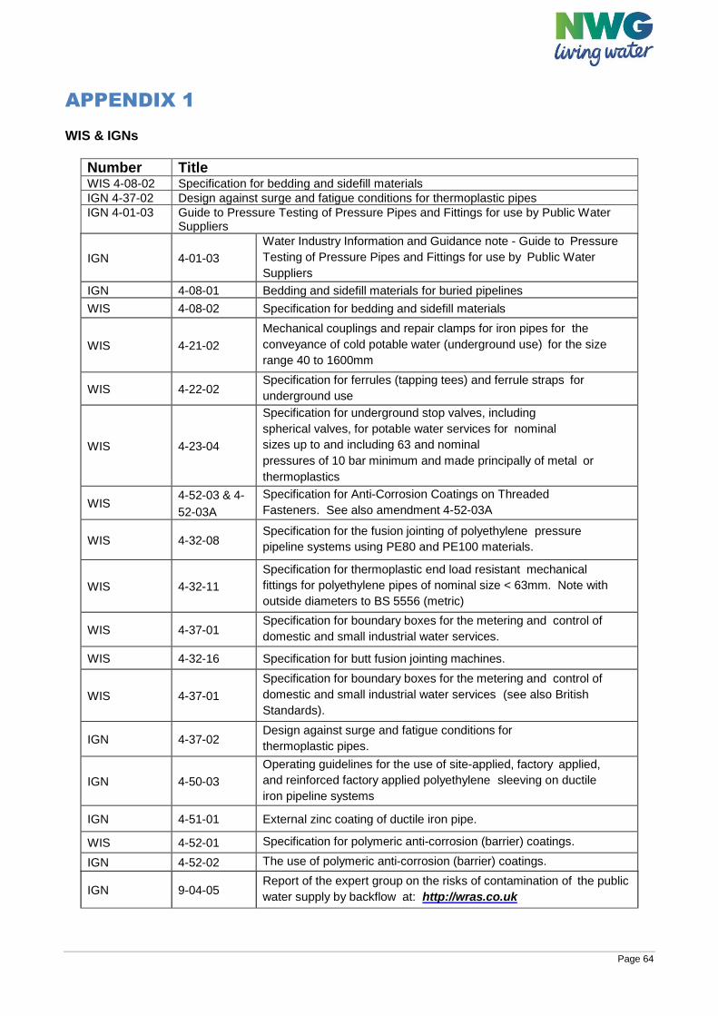
Page 64
APPENDIX 1 WIS & IGNs
Number Title WIS 4-08-02 Specification for bedding and sidefill materials
IGN 4-37-02 Design against surge and fatigue conditions for thermoplastic pipes
IGN 4-01-03 Guide to Pressure Testing of Pressure Pipes and Fittings for use by Public Water Suppliers
IGN 4-01-03
Water Industry Information and Guidance note - Guide to Pressure
Testing of Pressure Pipes and Fittings for use by Public Water
Suppliers
IGN 4-08-01 Bedding and sidefill materials for buried pipelines
WIS 4-08-02 Specification for bedding and sidefill materials
WIS 4-21-02
Mechanical couplings and repair clamps for iron pipes for the
conveyance of cold potable water (underground use) for the size
range 40 to 1600mm
WIS 4-22-02 Specification for ferrules (tapping tees) and ferrule straps for
underground use
WIS 4-23-04
Specification for underground stop valves, including
spherical valves, for potable water services for nominal
sizes up to and including 63 and nominal
pressures of 10 bar minimum and made principally of metal or
thermoplastics
WIS 4-52-03 & 4-
52-03A
Specification for Anti-Corrosion Coatings on Threaded
Fasteners. See also amendment 4-52-03A
WIS 4-32-08 Specification for the fusion jointing of polyethylene pressure
pipeline systems using PE80 and PE100 materials.
WIS 4-32-11
Specification for thermoplastic end load resistant mechanical
fittings for polyethylene pipes of nominal size < 63mm. Note with
outside diameters to BS 5556 (metric)
WIS 4-37-01 Specification for boundary boxes for the metering and control of
domestic and small industrial water services.
WIS 4-32-16 Specification for butt fusion jointing machines.
WIS 4-37-01
Specification for boundary boxes for the metering and control of
domestic and small industrial water services (see also British
Standards).
IGN 4-37-02 Design against surge and fatigue conditions for
thermoplastic pipes.
IGN 4-50-03
Operating guidelines for the use of site-applied, factory applied,
and reinforced factory applied polyethylene sleeving on ductile
iron pipeline systems
IGN 4-51-01 External zinc coating of ductile iron pipe.
WIS 4-52-01 Specification for polymeric anti-corrosion (barrier) coatings.
IGN 4-52-02 The use of polymeric anti-corrosion (barrier) coatings.
IGN 9-04-05 Report of the expert group on the risks of contamination of the public
water supply by backflow at: http://wras.co.uk
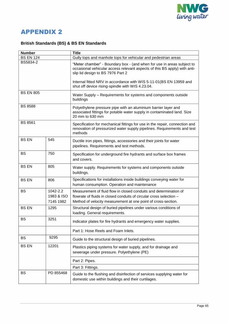
Page 65
APPENDIX 2 British Standards (BS) & BS EN Standards Number Title
BS EN 124 Gully tops and manhole tops for vehicular and pedestrian areas
BS5834-2 “Meter chamber” - Boundary box - (and when for use in areas subject to occasional vehicular access relevant aspects of this BS apply) with anti-slip lid design to BS 7976 Part 2 Internal fitted NRV in accordance with WIS 5-11-01(BS EN 13959 and shut off device rising-spindle with WIS 4.23.04.
BS EN 805 Water Supply – Requirements for systems and components outside buildings
BS 8588 Polyethylene pressure pipe with an aluminium barrier layer and associated fittings for potable water supply in contaminated land. Size 20 mm to 630 mm
BS 8561 Specification for mechanical fittings for use in the repair, connection and renovation of pressurized water supply pipelines. Requirements and test methods
BS EN 545 Ductile iron pipes, fittings, accessories and their joints for water
pipelines. Requirements and test methods.
BS 750 Specification for underground fire hydrants and surface box frames
and covers.
BS EN 805 Water supply. Requirements for systems and components outside
buildings.
BS EN 806 Specifications for installations inside buildings conveying water for
human consumption. Operation and maintenance
BS 1042-2.2
1983 & ISO
7145 1982
Measurement of fluid flow in closed conduits and determination of
flowrate of fluids in closed conduits of circular cross selection –
Method of velocity measurement at one point of cross-section.
BS EN 1295 Structural design of buried pipelines under various conditions of
loading. General requirements.
BS 3251 Indicator plates for fire hydrants and emergency water supplies.
Part 1: Hose Reels and Foam Inlets.
BS 9295 Guide to the structural design of buried pipelines.
BS EN 12201 Plastics piping systems for water supply, and for drainage and
sewerage under pressure. Polyethylene (PE)
Part 2: Pipes.
Part 3: Fittings.
BS PD 855468 Guide to the flushing and disinfection of services supplying water for
domestic use within buildings and their curtilages.
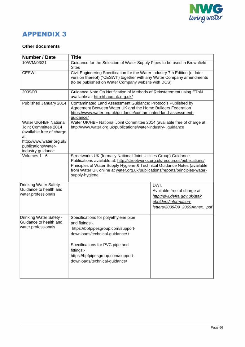
Page 66
APPENDIX 3 Other documents
Number / Date Title 10/WM/03/21 Guidance for the Selection of Water Supply Pipes to be used in Brownfield
Sites
CESWI Civil Engineering Specification for the Water Industry 7th Edition (or later version thereof) (“CESWI”) together with any Water Company amendments (to be published on Water Company website with DCS).
2009/03 Guidance Note On Notification of Methods of Reinstatement using EToN available at: http://hauc-uk.org.uk/
Published January 2014 Contaminated Land Assessment Guidance: Protocols Published by Agreement Between Water UK and the Home Builders Federation https://www.water.org.uk/guidance/contaminated-land-assessment-guidance/
Water UK/HBF National Joint Committee 2014 (available free of charge at: http://www.water.org.uk/publications/water-industry-guidance
Water UK/HBF National Joint Committee 2014 (available free of charge at: http://www.water.org.uk/publications/water-industry- guidance
Volumes 1 - 6 Streetworks UK (formally National Joint Utilities Group) Guidance Publications available at: http://streetworks.org.uk/resources/publications/
Principles of Water Supply Hygiene & Technical Guidance Notes (available from Water UK online at water.org.uk/publications/reports/principles-water-supply-hygiene
Drinking Water Safety - Guidance to health and water professionals
DWI,
Available free of charge at:
http://dwi.defra.gov.uk/stak
eholders/information-
letters/2009/09_2009Annex. pdf
Drinking Water Safety - Guidance to health and water professionals
Specifications for polyethylene pipe
and fittings:-.
https://bpfpipesgroup.com/support-
downloads/technical-guidance/ t.
Specifications for PVC pipe and
fittings:-
https://bpfpipesgroup.com/support-
downloads/technical-guidance/
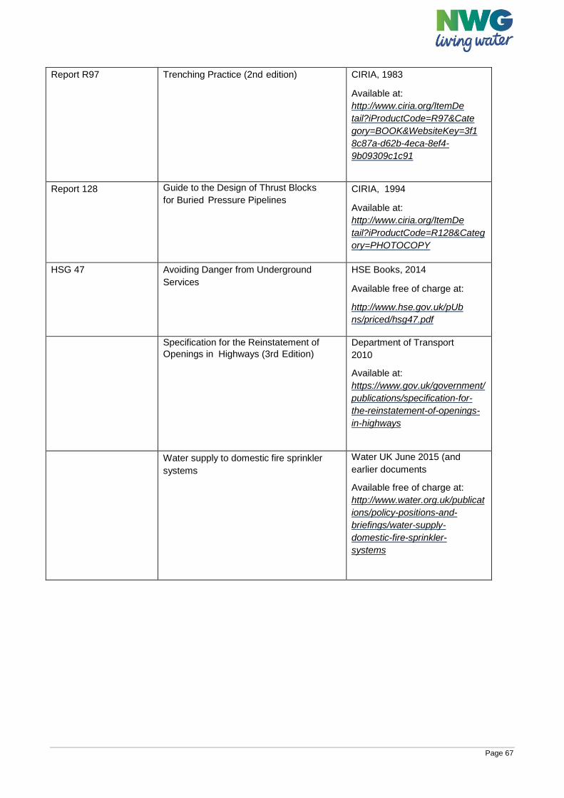
Page 67
Report R97 Trenching Practice (2nd edition) CIRIA, 1983
Available at:
http://www.ciria.org/ItemDe
tail?iProductCode=R97&Cate
gory=BOOK&WebsiteKey=3f1
8c87a-d62b-4eca-8ef4-
9b09309c1c91
Report 128 Guide to the Design of Thrust Blocks
for Buried Pressure Pipelines
CIRIA, 1994
Available at:
http://www.ciria.org/ItemDe
tail?iProductCode=R128&Categ
ory=PHOTOCOPY
HSG 47 Avoiding Danger from Underground
Services
HSE Books, 2014
Available free of charge at:
http://www.hse.gov.uk/pUb
ns/priced/hsg47.pdf
Specification for the Reinstatement of
Openings in Highways (3rd Edition)
Department of Transport
2010
Available at:
https://www.gov.uk/government/
publications/specification-for-
the-reinstatement-of-openings-
in-highways
Water supply to domestic fire sprinkler
systems
Water UK June 2015 (and
earlier documents
Available free of charge at:
http://www.water.org.uk/publicat
ions/policy-positions-and-
briefings/water-supply-
domestic-fire-sprinkler-
systems