Embed Size (px)
Citation preview
DESIGN & IMPLEMENTATION OF SMART ONLINE SWITCHING APPLIANCES
USING RASPBERRY PI
(Case study: Large Factory)
Final Year Project Proposal Submitted To Kampala International University in Partial Fulfillment
of the Requirements for the Award of the Degree
of
Bachelor of Science in Electrical Engineering
BY
MUSHABE AUGUSTUS
1153-03114-03772
Email: [email protected]
Contact: +256 757675601
SCHOOL OF ENGINEERING AND APPLIED SCIENCES (SEAS)
DEPARTMENT OF ELECTRICAL, TELECOM AND COMPUTER ENGINEERING
AUGUST 2019.

i
DECLARATION
I hereby declare that this project proposal is my own work, original and has not been submitted for
any academic award by any student to any other university.
Name:
Sign: ………………………………… Date: …………………………….

ii
APPROVAL
I have read and hereby recommend this Team Project Proposal entitled “Design and
implementation of smart online switching appliances using raspberry pi for acceptance by
Kampala International University in partial fulfillment of the requirements for the award of the
degree of Bachelor of Science in Electrical engineering of Kampala International University
PROJECT COORDINATOR
MR. ADABARA IBRAHIM
Signature…………………………… Date…………………………………
www.rootiancenter.com
www.eduraryschool.com

iii
DEDICATION
I dedicate this report to the glory of GOD, my guardians who have supported and sponsored me in
everything I have done; their advice is highly appreciated as well. I also would like to dedicate it to
all my beloved friends who have given me advice throughout my academic struggle.

iv
ACKNOWLEDGEMENT
Primarily I would like to express my thanks to the Almighty God whom without any of this would
have been possible.
More thanks goes to my Project Supervisors Mr. Adabara Ibrahim for his professional guidance
support and valuable suggestions. Also to my lecturers who gave me ideas, technical support and
spared their time to ensure my success in coming up with this project report.
I recognize the effort of my parents in their endeavors to support me financially. Their prayers,
support, guidance and sacrifices are highly appreciated.
Appreciation goes to my fellow students who helped me in the research process.

v
TABLE OF CONTENTS
DECLARATION ................................................................................................................................. i
APPROVAL ....................................................................................................................................... ii
DEDICATION................................................................................................................................... iii
ACKNOWLEDGEMENT ................................................................................................................. iv
TABLE OF CONTENTS ................................................................................................................... v
LIST OF FIGURES .......................................................................................................................... vii
LIST OF TABLES ........................................................................................................................... viii
ABSTRACT ...................................................................................................................................... ix
CHAPTER ONE ................................................................................................................................. 1
1.0 Introduction ............................................................................................................................... 1
1.1 General background of the study .............................................................................................. 1
1.2 Problem statement ..................................................................................................................... 3
1.3 Objectives of the study .............................................................................................................. 4
1.3.0 Main objective .................................................................................................................... 4
1.3.1 Specific objective ................................................................................................................ 4
1.4 Research Questions ................................................................................................................... 4
1.5 Significance of the study ........................................................................................................... 5
1.6 New features in the system ........................................................................................................ 5
1.7 Scope of the study ..................................................................................................................... 5
1.7.0 Geographical scope ............................................................................................................. 6
1.7.1 Time scope .......................................................................................................................... 6
1.7.2 Content scope ...................................................................................................................... 6
CHAPTER TWO ................................................................................................................................ 7
LITERATURE REVIEW ................................................................................................................... 7
2.0 Introduction ............................................................................................................................ 7
2.1 Existing related systems ............................................................................................................ 8
2.2 Review IoT development platforms. ....................................................................................... 11

vi
2.2.0 Raspberry Pi ...................................................................................................................... 11
CHAPTER THREE .......................................................................................................................... 12
METHODOLOGY ........................................................................................................................... 12
3.0 Introduction ........................................................................................................................... 12
3.1 Sampling methods ................................................................................................................... 12
3.1.1 Sample size ....................................................................................................................... 12
3.2 Data Collection Methods. ........................................................................................................ 13
3.3 Focused group discussions. ..................................................................................................... 13
3.3.1 Interviewing. ..................................................................................................................... 13
3.3.2 Observation. ...................................................................................................................... 14
3.4 Approaches to the system development. ................................................................................. 14
3.5 System development life cycle (SDLC) .................................................................................. 14
3.5 The block diagram .................................................................................................................. 16
CHAPTER FOUR ............................................................................................................................ 23
DATA PRESENTATION, ANALYSIS AND SYSTEM DESIGN ................................................. 23
4.0 Introduction ............................................................................................................................. 23
4.1 System Study ........................................................................................................................... 23
4.2 System Analysis ...................................................................................................................... 23
5.0 Introduction ............................................................................................................................. 27
5.1 Summary ................................................................................................................................. 27
5.2 Limitations .............................................................................................................................. 27
5.3 Conclusions. ............................................................................................................................ 28
5.4 Recommendations. .................................................................................................................. 28
5.5 Opportunity and Lesson Learned. ........................................................................................... 29
REFERENCES ................................................................................................................................. 30

vii
LIST OF FIGURES
Figure 1: block diagram .................................................................................................................... 16
Figure 2: circuit diagram .................................................................................................................. 17

viii
LIST OF TABLES
Table 1: Hardware Requirement ....................................................................................................... 25
Table 2: Software Requirements ...................................................................................................... 26

ix
ABSTRACT
Automation is becoming popular due to its numerous benefits. Smart online switching refers to
the control of home appliances and domestic features by local networking or data (Internet).
Artificial Intelligence provides us the framework to go real-time decision and automation for
Internet of Things (IoT).The work deals with discussion about different intelligent home
automation systems and technologies from a various features standpoint. The work focuses on
concept of home automation where the monitoring and control operations are facilitating through
smart devices installed in residential buildings. Heterogeneous home-automation systems and
technologies considered in review with central controller based (Arduino or Raspberry pi), web
based, email based, Bluetooth-based, mobile-based, SMS based, ZigBee based, Dual Tone Multi
Frequency-based, cloud-based and the Internet with performance.
This project presents the overall design of Electronic Appliance Automation System (EAAS) with
low cost and wireless system. This system is designed to assist and provide support in order to
eradicate or reduce the daily movement in the due course of switching on and off electrical
appliances in homes, office, industries. Also, the smart home concept in the system improves the
standard living at home. The switch mode and voice mode are used to control the home appliances.
The main control system implements wireless technology to provide remote access from smart
phone. The design remains the existing electrical switches and provides more safety control on the
switches with low voltage activating method. The switches status is synchronized in all the control
system whereby every user interface indicates the real time existing switches status. The system
intended to control electrical appliances and devices in house with relatively low cost design, user-
friendly interface and ease of installation.
Keywords: Internet, Local Area Network, Wi-Fi, Raspberry pi.

1
CHAPTER ONE
1.0 Introduction
Due to the advancement of wireless technology, there are several different of connections are
introduced such as GSM, WIFI, and Bluetooth. Each of the connection has their own unique
specifications and applications [2]. Among the four popular wireless connections that often
implemented in automation projects, WIFI is being chosen with its suitable capability. The
capabilities of WIFI are more than enough to be implemented in the design [5]. Also, most of the
current laptop/notebook or Smartphone come with built-in WIFI adapter. It will indirectly reduce
the cost of this system.
This project forwards the design of electronic appliance automation system using Raspberry pi, a
credit sized computer. Raspberry pi provides the features of a mini computer, additional with its
GPIO pins where other components and devices can be connected [1]. GPIO registers of raspberry
pi are used for the output purposes. We have design a power strip that can be easily connected to
GPIO Pins of the Raspberry pi.
The appliances are connected to the input/output ports of Raspberry pi along with the power strip
and their status is passed to the raspberry pi [4]. The android running OS in any phone connected to
a network can access the status of the home appliances via an application. It presents the design
and implementation of automation system that can monitor and control home appliances via
android phone or tablet.
1.1 General background of the study
More and more devices of our daily life are computer based. This trend can be seen in many
different areas of home equipment. Most communication systems, including landline phones,
cellphones, and -obviously- the Internet, are based on electronic components that run specifically
designed programs.

2
IoT is generally a scenario where network connectivity and computing capability was extended to
objects, sensors and all items normally not considered as computers can exchange, generate and
consume data with minimal human intervention. Rapid growth in technologies enhanced the
growth of IoT Environment and it was already developed in Industrial Wireless sensor Network.
The concept of combining computers, sensors, and networks to monitor and control devices has
existed for decades and the projections for the impact of IoT on the Internet and economy are
impressive, with some anticipating as many as 100 billion connected IoT devices and a global
economic impact of more than $11 trillion by 2025
The “Automation” concept has existed for many years. The terms “Smart”, “Intelligent Home”
followed and has been used to introduce the concept of networking appliances and devices in the
house. Home automation Systems (HASs) represents a great research opportunity in creating new
fields in engineering, and Computing.
HASs includes centralized control of lighting, appliances, security locks of gates and doors and
other systems, to provide improved comfort, energy efficiency and security system. HASs
becoming popular nowadays and enter quickly in this emerging market. However, end users,
especially the disabled and elderly due to their complexity and cost, do not always accept these
systems. Due to the advancement of wireless technology, there are several different of connections
are introduced such as GSM, WIFI, and Bluetooth. Each of the connection has their own unique
specifications and applications. Among the four popular wireless connections that often
implemented in HAS project, WIFI is being chosen with its suitable capability.
The capabilities of WIFI are more than enough to be implemented in the design. Also, most of the
current laptop/notebook or Smartphone come with built-in WIFI adapter. It will indirectly reduce
the cost of this system.
Automation is a technique, method, or system of operating or controlling a process by electronic
devices with reducing human involvement to a minimum. The fundamental of building an
automation system for an office or home is increasing day-by-day with numerous benefits.
Industrialist and researchers are working to build efficient and affordability automatic systems to

3
monitor and control different machines like lights, fans, AC based on the requirement. Automation
makes not only an efficient but also an economical use of the electricity and water and reduces
much of the wastage.
IoT grant to people and things to be connected Any-time, anyplace, with anyone, ideally using any
network and any service. Automation is another important application of IoT technologies. It is
the monitoring of the energy consumption and the Controlling the environment in buildings,
schools, offices and museums by using different types of sensors and actuators that control lights,
temperature, and humidity.
This project forwards the design of Electronic appliance automation system using Raspberry pi, a
credit sized computer. Raspberry pi provides the features of a mini computer, additional with its
GPIO pins where other components and devices can be connected.
GPIO registers of raspberry pi are used for the output purposes. We have design a power strip
that can be easily connected to GPIO Pins of the Raspberry pi. The home appliances are
connected to the input/output ports of Raspberry pi along with the power strip and their status is
passed to the raspberry pi. The android running OS in any phone connected to a network can
access the status of the home appliances via an application. It presents the design and
implementation of automation system that can monitor and control appliances via android phone
or tablet.
1.2 Problem statement
Today people are looking at ways and means to better their life-style using the latest technologies
that area available. Any new facility or hope appliance that promises to enhance their life-style is
grabbed by the consumers. The more such facilities and appliances are added, it becomes inevitable
to have easy and convenient methods and means to control and operate these appliances.
Conventional wall switches are located in different parts of a houses, offices, industries among
others and thus necessitates manual operations like to switch on or off these switches to control
various appliances. It gets virtually impossible to keep track of appliances that are running and
also to monitor their performances.

4
In this case, our electronic appliance automation system or control system is to address these
routines of moving in order to switch on and off of different electronics be it in office, home,
industry among others cheaply. In addition, the available systems have been too costly to install
unlike ours that only calls for installing some modules at the site, the on logs on our platform and
controls all devices as he or she pleases.
1.3 Objectives of the study
1.3.0 Main objective
The main objective of this research project is to design and develop an automation system
to eradicate the numerous movements involved in switching on and off the different
appliances like lights, Televisions, air conditioners, among others
1.3.1 Specific objective
To find out how appliance automation is done.
To interface Raspberry pi with other components.
To write the python and assemble the nod-red code.
To gather requirements needed to develop an appliance automation system
To design, develop and implement an appliance automation system.
1.4 Research Questions
How to find out how appliance automation is done.
How to interface Raspberry pi with other components.
How to write the python and assemble the nod-red code.
How to gather requirements needed to develop an appliance automation system
How to design, develop and implement an appliance automation system.

5
1.5 Significance of the study
Environmental
The system is not harmful to the environment as there is no pollution or an emission of radiation
related to it.
Saves a lot of energy
Industrial
The designed system prototype is as well suitable for industrial security lights control in an
automation manner, whereby one needs not to go to control room in order to switch the lights on
and off which as well saves energy as at times lights can be forgotten on which consumes a lot of
power hence higher bills for power.
Academics.
It increases the best way of using technology in day to day life.
The project can also be used for literature review by researchers in regard to use and advancements
in appliance automation system.
1.6 New features in the system
It amalgamates appliances and gives their control to any specific peoples through devices like
Smart phones remotely.
This system cuts down the costs of its installation making it affordable by almost everybody in a
way that one just needs to have a smart phone, let us install some electrical gadgets and circuits
then our client log on to our online platform then accesses his or her appliances registered on one’s
account assigned by us once one purchases our automation system.
1.7 Scope of the study
The study was carried out at the school of engineering and applied sciences (SEAS).

6
1.7.0 Geographical scope
The system is accessible with in the school of engineering and applied sciences (SEAS) found in
Kampala International University.
1.7.1 Time scope
The project took a period of 6 month.
1.7.2 Content scope
This project mainly focused on the content covering the design, development and implementation
of an electronic appliance automation system (EAAS).

7
CHAPTER TWO
LITERATURE REVIEW
2.0 Introduction
In this chapter, the research, location and analysis of the existing knowledge related to the subject
of inquiry are explored and cited. It ventures into the relationship of the proposed research for
purposes of good representation and critical review of the existing literature.
Electronic appliance automation system (EAAS) was the term used in this chapter to refer to
internet-based remote control of electronic appliances like fans, Television, Ovens, Percolators
among others in homes, offices, industries for remote control of security lights.
With the development of new electronic technologies and their integration with older, traditional
building technologies, smart home is at last becoming a real possibility. At first "home computer"
was an experimental system in 1966, then in the early 1980’s the smart home automation was
initiated as a project of the National Research Center of the National Association of Home Builders
(NAHB) with the cooperation of a collection of major industrial partners. Even though smart home
is not a new term for science society but it’s still far more away from people’s vision and audition.
Because recently various work is done with the design and general overview of the possible remote
access approaches for controlling devices, or in cases of simulating the smart home itself.
The design and implementation of an off-the-shelf Smart Home remote control application has
been limited to simply the computer applications and just in cases mobile and web applications
development. The "smart home" technology is one realization of home automation ideals using a
specific set of technologies. It's a home that has highly advanced automatic systems for lighting,
temperature control, security, appliances and own power generation system using sun tracking
solar panel. The smart house gets two parallel power sources. As a result, it makes smart house
more reliable and less power consumable nowadays.

8
2.1 Existing related systems
Internet Based Monitoring
Internet monitoring is one of the common approaches for remote monitoring. Many researchers
have worked in field of Internet based remote monitoring. (Saito et al., 2016) developed home
gateway system for interconnecting home network consisting of IEEE 1394 AV network and X10
power line home automation network with Internet. This provided remote access functions from
Internet for digital AV appliances like Digital Video Camera, Digital VCR connected to IEEE
1394 network and home appliances like TV, desk lamp, electric fan connected to X10 controller.
(Al-Ali and Al-Rousan) developed Java based home automation system via World Wide Web. The
home appliances were controlled from ports of embedded system board connected to PC based
server at home. (Alkar and Buhur, 2017) implemented Internet based wireless flexible solution
where home appliances are connected to slave node.
The slave nodes communicate with master node through RF and master node has serial RS232
link with PC server. The nodes are based on PIC 16F877 µc. PC server is formed of a user interface
component, the database and the web server components. An Internet page has been setup running
on a Web server. The user interface and the Internet front end are connected to a backend data base
server. The control of devices is established and their condition is monitored through the Internet.
GSM-SMS Based Monitoring
With the wide spread use of cellular networks, this approach is also popular when small amount
of data is to be transferred through the network. Extensive work has been carried out by researchers
using this approach especially in medical field. (Chen Peijiang and Jiang Xuehua, 2018) describe
a remote monitoring system based on SMS of GSM. The system includes two parts which are the
monitoring center and the remote monitoring station. The monitoring center consists of a computer
and a TC35 GSM communication module.
The computer and TC35 are connected by RS232. The remote monitoring station includes a TC35
GSM communication module, a MSP430F149 MCU, a display unit, various sensors, data
gathering and processing unit. (Scanaill et al., 2006) developed a tele-monitoring system, based
on short message service (SMS), to remotely monitor the long-term mobility levels of
9
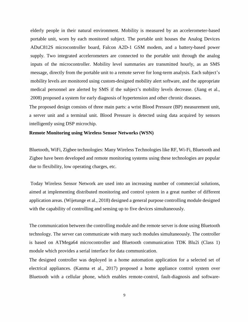
elderly people in their natural environment. Mobility is measured by an accelerometer-based
portable unit, worn by each monitored subject. The portable unit houses the Analog Devices
ADuC812S microcontroller board, Falcon A2D-1 GSM modem, and a battery-based power
supply. Two integrated accelerometers are connected to the portable unit through the analog
inputs of the microcontroller. Mobility level summaries are transmitted hourly, as an SMS
message, directly from the portable unit to a remote server for long-term analysis. Each subject’s
mobility levels are monitored using custom-designed mobility alert software, and the appropriate
medical personnel are alerted by SMS if the subject’s mobility levels decrease. (Jiang et al.,
2008) proposed a system for early diagnosis of hypertension and other chronic diseases.
The proposed design consists of three main parts: a wrist Blood Pressure (BP) measurement unit,
a server unit and a terminal unit. Blood Pressure is detected using data acquired by sensors
intelligently using DSP microchip.
Remote Monitoring using Wireless Sensor Networks (WSN)
Bluetooth, WiFi, Zigbee technologies: Many Wireless Technologies like RF, Wi-Fi, Bluetooth and
Zigbee have been developed and remote monitoring systems using these technologies are popular
due to flexibility, low operating charges, etc.
Today Wireless Sensor Network are used into an increasing number of commercial solutions,
aimed at implementing distributed monitoring and control system in a great number of different
application areas. (Wijetunge et al., 2018) designed a general purpose controlling module designed
with the capability of controlling and sensing up to five devices simultaneously.
The communication between the controlling module and the remote server is done using Bluetooth
technology. The server can communicate with many such modules simultaneously. The controller
is based on ATMega64 microcontroller and Bluetooth communication TDK Blu2i (Class 1)
module which provides a serial interface for data communication.
The designed controller was deployed in a home automation application for a selected set of
electrical appliances. (Kanma et al., 2017) proposed a home appliance control system over
Bluetooth with a cellular phone, which enables remote-control, fault-diagnosis and software-
10
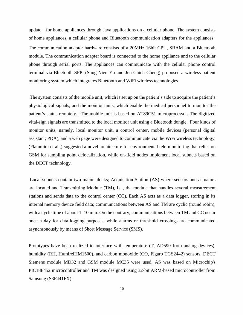
update for home appliances through Java applications on a cellular phone. The system consists
of home appliances, a cellular phone and Bluetooth communication adapters for the appliances.
The communication adapter hardware consists of a 20MHz 16bit CPU, SRAM and a Bluetooth
module. The communication adapter board is connected to the home appliance and to the cellular
phone through serial ports. The appliances can communicate with the cellular phone control
terminal via Bluetooth SPP. (Sung-Nien Yu and Jen-Chieh Cheng) proposed a wireless patient
monitoring system which integrates Bluetooth and WiFi wireless technologies.
The system consists of the mobile unit, which is set up on the patient’s side to acquire the patient’s
physiological signals, and the monitor units, which enable the medical personnel to monitor the
patient’s status remotely. The mobile unit is based on AT89C51 microprocessor. The digitized
vital-sign signals are transmitted to the local monitor unit using a Bluetooth dongle. Four kinds of
monitor units, namely, local monitor unit, a control center, mobile devices (personal digital
assistant; PDA), and a web page were designed to communicate via the WiFi wireless technology.
(Flammini et al.,) suggested a novel architecture for environmental tele-monitoring that relies on
GSM for sampling point delocalization, while on-field nodes implement local subnets based on
the DECT technology.
Local subnets contain two major blocks; Acquisition Station (AS) where sensors and actuators
are located and Transmitting Module (TM), i.e., the module that handles several measurement
stations and sends data to the control center (CC). Each AS acts as a data logger, storing in its
internal memory device field data; communications between AS and TM are cyclic (round robin),
with a cycle time of about 1–10 min. On the contrary, communications between TM and CC occur
once a day for data-logging purposes, while alarms or threshold crossings are communicated
asynchronously by means of Short Message Service (SMS).
Prototypes have been realized to interface with temperature (T, AD590 from analog devices),
humidity (RH, HumirelHM1500), and carbon monoxide (CO, Figaro TGS2442) sensors. DECT
Siemens module MD32 and GSM module MC35 were used. AS was based on Microchip's
PIC18F452 microcontroller and TM was designed using 32-bit ARM-based microcontroller from
Samsung (S3F441FX).

11
2.2 Review IoT development platforms.
2.2.0 Raspberry Pi
It is a credit-card-sized single microcontroller computer. Python as the main programming
language. It is easy to learn and suitable for real world applications. There are two main types of
pi first one is Model A has 25 6Mb RAM, one USB port and no network connection and Model
B has 512Mb RAM, 2 USB ports and an Ethernet port.
It has a Broadcom BCM2835 system on a chip which includes an ARMl176JZF -S 700 MHz
processor, Video Core IV GPU, and an SD card.
The chip specifically provides HDMI and there is no VGA support.
The Raspberry Pi allows peripherals and expansion boards to access the CPU by exposing the in
and outputs. The production board has a 26-pin 2.54mm (100mil) expansion header, arranged in a
2x13 strip. They provide 8 GPIO pins plus access to I2C, SPI, UART), as well as +3V3, +5V and
GND supply lines. Pin one is column 0 on the bottom row. Voltage levels are 3v3. There is no
over-voltage protection on the board - the intention is that people interested in serious interfacing
will use an external board with buffers, level conversion and analog I/O rather than soldering
directly onto the main board.
It is also possible to reconfigure some of the pins to provide a second I2C interface. Kernel boot
messages go to the UART at 115200bps.
2.2.1 Arduino
It is a microcontroller board, not fully computers. In this, written codes are simply executed
without any obstacle. It is an 8 bit Atmel AVR Microcontroller which comprises of 32K and 512K
of onboard flash memory, 2K of RAM, runs at 884MHz clock speeds with voltages of 2.7V-
12V.programming is done using C and carries no operating system.
The code is written in the computer and then sent through USB cable for execution. Its construction
simply covers digital input-output pins that are between 9-54 AND 6-12 analog input pins. Its
power consumption is less than 0.5 watt.
12
CHAPTER THREE
METHODOLOGY
3.0 Introduction
This chapter presents the description of methods that were used to achieve the objectives of the
proposed system. It focuses on detailed description of the data collection techniques that were
employed in coming up with the proposed system. The chapter also looks at the relevant tools and
research approaches that were taken in analyzing, planning, design and implementation of the
system.
3.1 Sampling methods
In this report we used purposive and stratified random sampling.
According to Ashley Crossman, introduction to sociology of Social Sciences (2017) A purposive
sample is a non-probability sample that is selected based on characteristics of a population and the
objective of the study. We used purposive sampling to get the sample for the study from
receptionists, secretaries, directors and deans because of their small size and projected reliable
information that we would get from them. Because the student population was big, in thousands
of numbers, we used simple random sampling method to get the sample size from students. This
is because Stratified random sampling is a method of sampling that involves the division of a
population into smaller groups known as strata. In stratified random sampling, the strata are formed
based on members' shared attributes or characteristics. These subsets of the strata are then pooled
to form a random sample.
These subsets of the strata are then combined to form a random sample.
3.1.1 Sample size
In this research project we used purposive and stratified random sampling techniques due to the
large population or samples that the research covers. These include the different departments in
the school and also the different homes to check on the adaptability of our proposed system.
The study population was divided into strata for easy for easy manipulation then later computed
to represent the entire target population of the research study.

13
Now suppose we have a population size N divided into K strata. We take a stratified random
sample with ni observations in the ith stratum, which has population size Ni and population
proportion of attributes equal to Pi. Let Pi be the sample proportion in the ith stratum. Our overall
sample size is n = Ei and the “pooled” estimate of p, strata, weights the sample proportion from
each stratum according to the population size from the strata.
3.2 Data Collection Methods.
The following methods were used during data collection: Observation, Interviewing and focused
group discussion as our research methods. we were able to gather raw data from different hospitals
and the general public of school of computing and information technology where existing details
on the current system were obtained. Verbal interview techniques were used to interview peoples
from the different areas of Kampala district.
3.3 Focused group discussions.
A focus group discussion was held between some peoples for example at the school and the team
members to whom the issue seemed relevant. This was because it provided space to discuss
particular topics in context where people are allowed to agree or disagree with each other, thereby
enabling us to identify or spot out the core values that were be implied in our system.
3.3.1 Interviewing.
For the purposes of this research, in depth interviews were carried out. In depth interviews are
personal and unstructured interviews, whose aim is to identify participant’s emotions, feelings,
and opinions regarding a particular research subject.
The main advantage of personal interviews is that they involve personal and direct contact
between interviewers and interviewees, as well as eliminate non-response rates, but interviewers
need to have developed the necessary skills to successfully carry an interview.
14
3.3.2 Observation.
The mode of operation of different electronic appliances were noted being manual for example the
switching on and off of lights in offices at the school of computing and information technology.
3.4 Approaches to the system development.
The system development life cycle (SDLC) we chose to use was the spiral model and aspects of
risk analysis. This is because the spiral model is a risk-driven process model generator for software
projects. Based on the unique risk patterns of a given project, the spiral model guides a team to
adopt elements of one or more process models, such as incremental, waterfall prototyping.
We also used different aspects from other models like prototyping which helped us come up with
system definition and analysis, data flow diagrams (DFD) were used to show the flow of data in
the system.
Due to the variances to be encountered in that process, the system was developed using spiral
model approach due to its flexibility during development processes. A key concept of the spiral
approach is the focus on Risk. Although there are many choices about what to focus on in each
iteration, the spiral model recommends identifying risk factors that must be studied and mitigated.
Iterations are used to divide a very large, complex problem into smaller, more easily managed
problems. Each small problem is solved in turn until the large problem is solved.
3.5 System development life cycle (SDLC)
At Rocky Mountain Outfitters, one of Barbara Halifax’s initial jobs as the project manager for the
customer support system project is to make decisions about the approach used to develop the
system. All of the options described under this subheading are open to her. We will not describe
her final decisions, though, because we use the customer support system example throughout this
text as we present more details about all approaches.
Systems analysts solve business problems. For problem-solving work to be productive, it needs to
be organized and goal oriented. Analysts achieve these results by organizing the work into projects.
A project is a planned undertaking that has a beginning and an end and that produces a desired

15
result or product. The term system development project describes a planned undertaking that
produces a new information system. Some system development projects are very large, requiring
thousands of hours of work by many people and spanning several calendar years.
Many system development projects are smaller, lasting a month or two. For a system development
project to be successful, the people developing the system must have a detailed plan to follow.
Success depends heavily on having a plan that includes an organized, methodical sequence of tasks
and activities that culminate with an information system that is reliable, robust, and efficient.
One of the key, fundamental concepts in system development is the systems development life
cycle. Businesses and organizations use systems to support all the many, varied processes that a
business needs to carry out its functions. There are many different kinds of information systems,
and each has its own focus and purpose in supporting business processes. Each one of these
information systems has a life of its own, and we, as system developers, refer to this idea as the
life cycle of a system.
During the life of an information system, it is first conceived as an idea; then it is designed, built,
and deployed during a development project; and finally it is put into production and used to support
the business. However, even during its productive use, a system is still a dynamic, living entity
that is updated, modified, and repaired through smaller projects. This entire process of building,
deploying, using, and updating an information system is called the systems development life cycle,
or SDLC.
In today’s diverse development environment, many different approaches to developing systems
are used, and they are based on different SDLCs. As you might suppose, some approaches have
been used for a long time and have varying rates of success. In the ever- changing world of
information technology, new and unique approaches to building systems have emerged, which also
have varying success rates. Although it is difficult to find a single, comprehensive classification
system that encompasses all of the approaches, one useful technique is to categorize SDLC
approaches according to whether they are more predictive or adaptive.

16
These two classifications represent the end points of a continuum from completely predictive to
completely adaptive these four groups of activities planning, analysis, design, and implementations
are sometimes referred to as phases and they are the elements that provide the framework for
managing the project.
Another phase, called the support phase includes the activities needed to upgrade and maintain the
system after it has been deployed. The support phase is part of the overall SDLC, but it is not
normally considered to be part of the initial development project.
3.5 The block diagram
Figure 1: block diagram
17
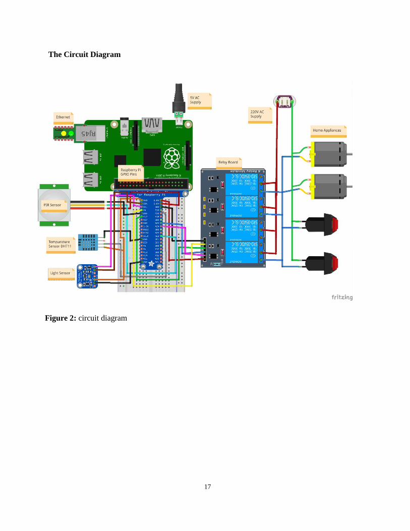
The Circuit Diagram
Figure 2: circuit diagram
18
Analysis phase (activities).
The primary objective of the analysis activities is to understand and document the business needs
and the processing requirements of the new system. Analysis is essentially a discovery process.
The key words that drive the activities during analysis are discovery and understanding.
Six primary activities are considered part of this phase:
Gather information.
Define system requirements.
Build prototypes for discovery of requirements.
Problem domain- the area of the user’s business that needs an information system solution and that
is being researched. The analysts obtain information about the problem domain by observing the
users as they do their work; by interviewing and asking questions of the users; by reading existing
documents about procedures, business rules, and job responsibilities; and by reviewing existing
automated systems. In addition to gathering information from the users of the system, the analysts
should consult other interested parties. They may include middle management, senior executives,
and at times even external customers. Gathering information is the core activity for discovery and
understanding.
But it is not sufficient simply to gather information. Analysts must review, analyze, and structure
the information obtained so that they can develop an overall understanding of the new system’s
requirements. This activity is called defining the system requirements, and the primary technique
that is used is drawing diagrams to express and model the new system’s processing requirements.
As we discussed earlier, one important activity that can help an analyst gather and understand the
requirements is to build a prototype of pieces of the new system. Then users can review them.
Users often find it easier to express their needs by reviewing working prototypes of alternatives.

19
“A picture is worth a thousand words” is as true in defining system requirements as it is in general,
and a prototype is the “picture” that can elicit valuable insights from end users.
Design phase (activities).
The objective of the design activities is to design the solution system based on the requirements
defined and decisions made during analysis. High-level design consists of developing an
architectural structure for the software components, databases, user interface, and operating
environment. Low-level design entails developing the detailed algorithms and data structures that
are required for software development. Seven major activities must be completed during the design
phase:
Design and integrate the network.
Design the application architecture.
Design the user interfaces.
Design the system interfaces.
Design and integrate the database.
Prototype for design details.
Design and integrate the system controls.
Design activities are closely interrelated and generally are all done with substantial overlap.
The network consists of the computer equipment, network, and operating system platforms that
will house the new information system. Many of today’s new systems are being installed in
network and client/server environments. Design includes configuring these sequences of
interactions. Most new information systems must also communicate with other, existing systems,
so the design of the method and details of these communication links must also be precisely
defined. These are called system interfaces.
Databases and information files are an integral part of information systems for business. The
diagrams of the new system’s data storage requirements, developed during analysis, are used to
design the database that will support the application portion of the new system. At times, the
20
database for the specific system must also be integrated with information databases of other
systems already in use.
During design, it is often necessary to verify the correctness or workability of the proposed design.
Again, one important verification method is to build working prototypes of parts of the system to
ensure that it will function correctly in the operating environment. In addition, analysts can test
and verify alternative design strategies by building prototypes of the new system. Sometimes, if
the prototypes are built correctly, they can be saved and used as part of the final system.
Finally, every system must have sufficient controls to protect the integrity of the database and the
application program. Because of the highly competitive nature of the global economy and the risks
associated with technology and security, every new system must include adequate mechanisms to
protect the information and assets of the organization. These controls should be integrated into the
new system while it is being designed, not after it has been constructed.
Implementation phase (activities).
Implementation activities result in the final system being built, tested, and installed. The objective
is not only to produce a reliable, fully functional information system, but also to ensure that the
users are all trained and that the organization is ready to benefit as expected from use of the system.
All the prior activities must come together to culminate in an operational system. Five major
activities make up the implementation phase:
Construct software components.
Verify and test.
Convert data.
Train users and document the system.
Install the system.
The software can be constructed through various techniques. The conventional approach is to write
computer programs using a language such as Visual Basic, C#, or Java. Other techniques, based
on development tools and existing components, are becoming popular today. The software must
also be tested, and the first kind of testing verifies that the system actually works. Additional testing
is also required to make sure that the new system meets the needs of the system’s users.

21
Support phase (activities).
The objective of the support activities is to keep the system running productively during the years
following its initial installation. The support activities begin only after the new system has been
installed and put into production, and it lasts throughout the productive life of the system. The
expectation for most business systems is that the system will last for years. During support,
upgrades or enhancements may be carried out to expand the system’s capabilities, and they will
require their own development projects. Three major activities occur during support:
Maintain the system.
Enhance the system.
Support the users.
Every system, especially a new one, contains components that do not function correctly. Software
development is complex and difficult, so it is never error-free. Of course, the objective of a well-
organized and carefully executed project is to deliver a system that is robust and complete and that
gives correct results. However, because of the complexity of software and the impossibility of
testing every possible combination of processing requirements, there will always be conditions
that have not been fully tested and thus are subject to errors. In addition, business needs and user
requirements change over time. Key tasks in maintaining the system include both fixing the errors
(also known as fixing bugs) and making minor adjustments to processing requirements. Usually a
system support team is assigned responsibility for maintaining the system.
Most newly hired programmer analysts begin their careers working on system maintenance
projects. Tasks typically completed include changing the information provided in a report, adding
an attribute to a table in a database, or changing the design of Windows or browser forms. These
changes are requested and approved before the work is assigned, so a change request approval
process is always part of the system support phase.
During the productive life of a system, it is also common to make major modifications. At times,
government regulations require new data to be maintained or information to be provided. Also,
changes in the business environment new market opportunities, new competition, or new system
infrastructure necessitate major changes to the system. To implement these major system

22
enhancements, the company must approve and initiate an upgrade development project. An
upgrade project often results in a new version of the system.
During your career, you may have the opportunity to participate in several upgrade projects.
SOURCE: Customer support system project, At Rocky Mountain Outfitters by project manager
Barbara
Halifax’s accessed on 12th January 2019.

23
CHAPTER FOUR
DATA PRESENTATION, ANALYSIS AND SYSTEM DESIGN
4.0 Introduction
This chapter focuses on the data analysis and presentation, system analysis and design, strength
and weakness of the current system and the context level diagram.
4.1 System Study
There was a thorough study of the existing systems that is manual and perhaps tires without
automation. This was done in order to understand the loop holes before developing the electronic
appliance automation system (EAAS) for school of computing and information technology and
was achieved by use of Data Collection Methods like questionnaires, interviews and observations.
4.2 System Analysis
The analysis of the requirements acquired in the requirements identification phase led to the
development of the first prototype of the system , the first prototype was basically be back-end
the front end part of it will be included in the next prototypes of the system. The back end was
developed using python 3.5.4. the sqlite3 was the database used to store lecturer’s and
administrator’s details which were used to log into the system.
Data processing models like data flows diagrams, entity relationships diagrams and context models
will be used during system design. This is so as to clearly understand the flow of information
between processes geared by the three fold design: the conceptual, logical and physical designs.
The conceptual design involves identifying the relationships between the major entities interacting
with the system and their matching attributes and identifying the relationships between entities
where entity relationship diagram was the end product. The system design objectives includes:
Usability, performance, reliability, software architecture and package.

24
4.2.0 Existing medical service delivery System.
Refer to the literature review, observation, interviews and questionnaires as explained in chapter
three, it should be noted that in school of computing and information technology, we were able to
analyze existing as discussed below.
There was no automation so one had to make movements to different corners of the office in order
to switch on the lights, fan, Television among others hence tiresome and perhaps too manual mode
of functionality was experienced.
The clients recommended that the proposed system should be user friendly, able to respond without
errors, operate without bias, and observance of time factor. Context diagrams, Data flow diagrams
were used in the analysis and design of the system.
4.2.1 Requirements Specifications
After analyzing the data collected, we formulated a number of requirements namely user
requirement, system hardware software attribute. These were grouped as user, functional,
nonfunctional and systems requirements.
4.2.2 User Requirement
During data collection, we investigated and found out how currents system was tiresome and
expensive and perhaps unfavorable to some group of people like the elderly. We found out how
best to address this problem hence development of the electronic appliance automation system.
4.2.3 Functional and Non Functional Requirements
The following is the desired functionality of the new system. The system should grant access to
the user from any place, any time, any day hence available and accessible 24/7/365.
And non-functional requirements include the following
The system must verify and validate all user input and users must be notified in case of errors
detected in the course of using the system.

25
Table 1: Hardware Requirement
Hardware Minimum System requirement
Processor 2.4 GHZ processor speed
Memory 128 MB RAM (256 MB Recommended)
Disk space 80 GB (including 20 GB for database
Management system)
Display 800 x 600 colors (1024 x 768 High color- 16 bit
Recommended)
In addition, programming requires ;- Raspberry Pi B+ (along with a microSD card, a microUSB
cable, and an HDMI cable)
An eight (8) channel relay switch module, Wires of 1.5 volts (1o m) and 2.5 volts (1o m), Electric
connectors, Insulation Tape, Taster and applier, Two (2) bulbs thus to say sitting room and security
light, Fan and Percolator / electrical kettle.
Extension cable, Smartphone with internet connection.
USB Wi-Fi dongle
T-Cobbler Kit
Jumper wires (both male to female and ma
Breadboard
Laptops
The table above shows hardware components of the machine (computer) that allows the system to
function, the personal digital assistants like smart phones running android versions can access the
system and on the web.

26
Table 2: Software Requirements
Software Minimum System requirement
Operating System Linux distribution, Android
.Net framework Version 3.5 or higher
The table above shows software requirements recommended to enable the system
to run.

27
CHAPTER FIVE
SUMMARY, LIMITATION, CONCLUSION AND RECOMMENDATIONS
5.0 Introduction
This chapter describes the objectives of the system stipulated in earlier chapter, limitation of the
system conclusion and recommendation of the system
5.1 Summary
This project presents the overall design of Electronic Appliance Automation System (EAAS) with
low cost and wireless system. This system is designed to assist and provide support in order to
eradicate or reduce the daily movement in the due course of switching on and off electrical
appliances in homes, office, industries. Also, the smart home concept in the system improves the
standard living at home. The switch mode and voice mode are used to control the home appliances.
The main control system implements wireless technology to provide remote access from smart
phone. The design remains the existing electrical switches and provides more safety control on the
switches with low voltage activating method. The switches status is synchronized in all the control
system whereby every user interface indicates the real time existing switches status. The system
intended to control electrical appliances and devices in house with relatively low cost design, user-
friendly interface and ease of installation.
5.2 Limitations
This section describes those services that are not provided by the system and those include the
following.
The project development process was too costly to us as developers in terms of purchasing the
python raspberry pi, relay switch modules, bulbs among other gadgets for purposes of prototyping
of the project.
The application favors most those who are fluent or know English since it’s the official language
mostly used in Uganda.

28
One must have a smart phone or computer and be connected to the network in order to use the
application which calls for data connection charges hence may be costly to some people yet eases
life due to its mode of functionality
5.3 Conclusions.
The prime objective of our project is to use the Smartphone to control the electronic appliances
effectively. this project is based on the Raspberry pi, Android platform jinja and Python. These
platforms are Free Open Source Software. So the overall implementation cost is low and can be
easily configured.
User can easily interact with the android phone/tablet. The user can send commands via the switch
mode or speech mode. The data are being analyzed by the application and are sent over a network.
The Raspberry pi acts as a server, analyses the data and activates the GPIO (General Purpose Input
Output) Pins. The GPIO Pins are connected to the relays switch which activated the required home
appliances.
In this way, automation process is carried out. This is a simple prototype. Using this as a reference
further it can be expanded to many other programs.
5.4 Recommendations.
Training of all peoples expected to use the electronic appliance automation system in homes,
offices, industries to ensure proper handling and functionality of the system. Since the system
depends of electric circuit, in case of any problem on the system call the system developer for
rectification.
The system need internet connectivity in order to be accessible anywhere, any time. The users can
as well have a dedicated control room for controlling light and also house all the necessary circuits
for safety reasons.

29
5.5 Opportunity and Lesson Learned.
During the course of this project, we were able to understand better how internet of things systems
are developed and maintained as well as knowing the some of the different systems developed so
far in automation domain as an endeavor to provide a sufficient and convenient service delivery
in different sectors of education, health organizations, industrial sector and residences. This was
effectively done through reading of literature and research. The whole process of developing the
system was a challenging task which came along with learning new technologies and programming
techniques as a way of implementing the different functionalities of the application or system.
Furthermore, this introduced us to carrying out research, reviewing literatures and consulting other
knowledgeable personnel in the field of systems development. This practice was too fundamental
in the development of this application.

30
REFERENCES
1. Ahmed ElShafee, Karim Alaa Hamed,” Design and Implementation of a WiFi Based Home
Automation System”, International Journal of Computer, Electrical, Automation, Control and
Information Engineering Vol: 6, No: 8, 2017.
2. Hayet Lamine and Hafedh Abid , ”Remote control of a domestic equipment from an
Android application based on Raspberry pi card”, IEEE transaction 15th international
conference on Sciences and Techniques of Automatic control & computer engineering -
STA'2014, Hammamet, Tunisia, December 21-23, 2018.
3. Kim Baraka, Marc Ghobril, Sami Malek, Rouwaida Kanj, Ayman Kayssi “Low cost
Arduino/Android-based Energy-Efficient Home Automation System with Smart Task
Scheduling” , 2013 Fifth International Conference on Computational Intelligence,
Communication Systems and Networks.
4. https://docs.python.org/
5. http://developer.android.com/training/index.html
6. http://elinux.org/RPi_Hub
7. http://www.raspberrypi.org/
8. http://stackoverflow.com/
9. http://electronics.howstuffworks.com/
10. N. Sriskanthan and Tan Karand. “Bluetooth Based Home Automation System”. Journal of
Microprocessors and Microsystems, Vol. 26, pp.281-289.
1. 11. Muhammad Izhar Ramli, Mohd Helmy Abd Wahab, Nabihah, “TOWARDS
SMART HOME: CONTROL ELECTRICAL DEVICES ONLINE” ,Nornabihah Ahmad
International Conference on Science and Technology: Application in Industry and Education
(2006) 9. E. Yavuz, B. Hasan, I. Serkan and K. Duygu. “Safe and Secure PIC Based Remote
Control Application for Intelligent Home”. International Journal of Computer Science and
Network Security, Vol. 7, No. 5, May 2017 10.
11. Amul Jadhav, S. Anand, Nilesh Dhangare, K.S. Wagh “Universal Mobile Application
Development (UMAD) On Home Automation” Marathwada Mitra Mandal’s Institute of
Technology, University of Pune, India Network and Complex Systems ISSN 2224-610X
(Paper) ISSN 2225-0603 (Online) Vol 2, No.2, 2017
12. Internet Society; Internet of Things Overview; [online] Available: www.internetsociety.org
31
13. The Intel IoT Platform reference architecture specification white paper.[online]
Available: http://www.intel.in 3. Twinkle Gondaliya ,”A Survey on an Efficient IOT Based
Smart Home”, International Journal of Review in Electronics and Communication Engineering
Volume 4, No 1 February 2017.
14. Gaurav Tripathi, Dhananjay Singh, and Antonio J. Jara, "A survey of Internet-of-Things:
Future Vision, Architecture, Challenges and Service", IEEE World Forum on Internet of
Things (WF-IoT), 2014, pp. 287-292
15. Sarita Agrawal, and Manik Lal Das, "Internet of Things – A Paradigm Shift of Future
Internet Applications", International Conference on Current Trends in Technology, December,
2011.
16. IOT Analytics: Market Insight for Internet of Things, https://iot-analytics.com/10-internet- of-
things-applications.
17. Pooja N.Pawar1, Shruti Ramachandran2, Nisha P.Singh3, Varsha V.Wagh4, “A Survey on
Internet of Things Based Home Automation System”,International Journal of Innovative
Research in Computer and Communication Engineering, Vol. 4, Issue 1, January 2018.
2. 19. Dhakad Kunal1, Dhake Tushar2, Undegaonkar Pooja3, Zope Vaibhav4, Vinay Lodha5,”
Smart Home Automation using IOT”, International Journal of Advanced Research in
Computer and Communication Engineering Vol. 5, Issue 2, February 2017.

1