Embed Size (px)
Citation preview
International Research Journal of Engineering and Technology (IRJET) e-ISSN: 2395-0056
Volume: 03 Issue: 01 | Jan-2016 www.irjet.net p-ISSN: 2395-0072
© 2016, IRJET ISO 9001:2008 Certified Journal Page 420
Design & Analysis of Centrifugal Pump Impeller by FEA
Mane Pranav Rajanand, ME Student, Department of Mechanical Engineering V.V.P. Institute of
Engineering & Technology, Solapur, Maharashtra, India
---------------------------------------------------------------------***---------------------------------------------------------------------Abstract - A centrifugal pump is a rot dynamic pump
that uses a rotating impeller to increase the pressure of a
fluid. Centrifugal pumps are commonly used to move
liquids through a piping system. The fluid enters the pump
impeller along or near to the rotating axis and is
accelerated by the impeller, flowing radially outward into
a diffuser or volute chamber (casing), from where it exits
into the downstream piping system. Its purpose is to
convert energy of a prime mover (a electric motor or
turbine) first into velocity or kinetic energy and then into
pressure energy of a fluid that is being pumped.
Centrifugal pumps are used for large discharge through
smaller heads. centrifugal pumps converts mechanical
energy from a motor to energy of a moving fluid; some of
the energy goes into kinetic energy of fluid motion, and
some into potential energy, represented by a fluid
pressure or by lifting the fluid against gravity to a higher
level. The transfer of energy from the mechanical rotation
of the impeller to the motion and pressure of the fluid is
usually described in terms of centrifugal force, especially
in older sources written before the modern concept of
centrifugal force as a fictitious force in a rotating reference
frame was well articulated. The concept of centrifugal
force is not actually required to describe the action of the
centrifugal pump. In this paper analysis on MS & SS pump
impeller is done in order to optimize strength of
centrifugal pump. This paper gives the static & Modal
analysis of MS & SS Pump Impeller to check strength of
Pump & vibrations produced by pump.
Key Words: Analysis, Pump Impeller, Optimization,
MS, SS, etc.
1. PROBLEM IDENTIFICATION:
Most of the centrifugal pump impellers are made up with
Mild Steel which has more density. This is main cause of
high weight of pump. In addition to this it has high
corrosion and less fatigue strength.
The mild steel can be replaced with alloy material (e.g. SS,
Inconel, Aluminum alloys) to reduce the weight, improve
corrosion resistance and fatigue strength is more as
compare to different alloys material and composite
material. Due to less stiffness, deformations produced for
the same material is more as compared to composite
material and different alloys.
2. LITERATURE SURVEY :
[1]. A Syam Prasad, BVVV Lakshmipathi Rao, A Babji, Dr P
Kumar Babu , “Static and Dynamic Analysis of a Centrifugal
Pump Impeller” Alloys are playing major role in many
engineering applications. They offer outstanding
mechanical properties, flexibility in design capabilities,
and ease of fabrication. Additional advantages include
light weight and corrosion resistance, impact resistance,
and excellent fatigue strength. In this paper study of static
and modal analysis of a centrifugal pump impeller which is
made of three different alloy materials. (viz., Inconel alloy
740, Incoloy alloy 803, Warpaloy) The best material for
design of impeller is Inconel 740. Specific modulus of
Inconel 740 obtained in static analysis is 10 % higher than
other material. The natural frequency in modal analysis is
6% higher than other material. The deformation of
Inconel 740 in static analysis is reduce by 12%.
[2] Karthik Matta, Kode Srividya, Inturi Prakash , “Static
and Dynamic Response of an Impeller at Varying Effects”

International Research Journal of Engineering and Technology (IRJET) e-ISSN: 2395-0056
Volume: 03 Issue: 01 | Jan-2016 www.irjet.net p-ISSN: 2395-0072
© 2016, IRJET ISO 9001:2008 Certified Journal Page 421
An impeller is a rotating component of a centrifugal
pump, usually made of iron, steel, bronze, brass, aluminum
or plastic. The modeling of the impeller was done by using
solid modeling software, CATIA V5 R18. It is proposed to
design a blower with composite material, analyze its
strength and deformation using FEM software. In order to
evaluate the effectiveness of composites and metal blower
and impeller using FEA packaged (ANSYS). Modal analysis
is performed on both Aluminum and composite centrifugal
blower impeller to find out first 5 natural frequencies. If
number of blade and outer diameter increases stresses
and deformation also increases all are allowable limit.
Total analysis result compares and found that composite
materials are having less deformation and stresses.
[3]. G. Kalyan, K.L.N. Murty. “Design and Optimization of
Centrifugal Pump Guide Vanes” In this paper an impeller
of a centrifugal pump is designed and modeled in 3D
modeling software Pro/Engineer.. Materials used are steel
and aluminum. The optimization of the impeller design is
done by observing the results obtained from the analysis
performed. The results considered are stress frequency
velocity pressure flow rates. Analysis is done in ANSYS.
By observing the structural analysis result the stresses by
increasing number of blades andincreasing the angle of
blade. When Aluminum material is used the stresses are
less than that of steel. By observing modal analysis results
the frequencies are reducing by increasing the number of
blade .
[4]. Pramod J. Bachche1, R.M.Tayade “Finite Element
Analysis of Shaft of Centrifugal Pump” Centrifugal pump is
world one of the oldest water pumping devises. In this
paper study Shaft of centrifugal pump for static and
dynamic analysis. The shaft is analyzed by using finite
element analysis technique for stresses and deflections.
The total work is carried out in two stages first stage is
static analysis. In this stage pump shaft is analyzed for
stresses and deflection and same results are verified using
graphical integration method. And second for dynamic
analysis, in this stage result obtained by static analysis are
used to calculate dynamic forces coming in pump shaft.
Again shaft is analyzed in dynamic input condition and
results are verified by using graphical integration method.
Maximum deflection and stress are generated to minimum
flow condition. Maximum dynamic deflection is obtained
11% less than allowable deflection and Maximum stresses
for dynamic is obtained 18% less than allowable tensile
strength.
[5] S.Rajendran and Dr. K Purushothaman “Analysis of
centrifugal pump impeller using ANSYS-CFX”
In this paper analysis of centrifugal pump impeller design
is carried out using ANSYS-CFX. It is most common pump
used in industries and domestic application. The complex
internal flow in centrifugal pump impeller can predicted
by ANSYS-CFX. A centrifugal pump is kinetic device. Liquid
entering the pump receives kinetic energy from the
rotating impeller. The centrifugal action of impeller
accelerates the liquid to high velocity, transferring
mechanical (rotational) energy to the liquid. The flow
pattern, pressure distribution in blade passage and blade
loading of centrifugal pump impeller are discussed in this
paper. Centrifugal pump impeller without volute casing is
solved at designed mass flow rate is high. Total efficiency
of pump is 30% increases.
[6].Static Analysis of Centrifugal Blower Using Composite
Material 1Mr M.Sampathkumar, 2Mr.Dsvsra Varaprasad,
3Mr.Vijaykumar
This paper is static and model analysis of centrifugal
blowers using composite materials Centrifugal blowers
are used in naval applications and motors which have high
noise levels. The noise generated by a rotating component
is mainly due to random loading force on the blades and
periodic iteration of incoming air with the blades of the
rotor. The Contemporary blades in naval applications are
made up of Aluminum or Steel and generate noise that
International Research Journal of Engineering and Technology (IRJET) e-ISSN: 2395-0056
Volume: 03 Issue: 01 | Jan-2016 www.irjet.net p-ISSN: 2395-0072
© 2016, IRJET ISO 9001:2008 Certified Journal Page 422
causes disturbance to the people working near the blower.
The present work aims at observing the choice of E-Glass
as an alternative to metal for better vibration control. E-
Glass, known for their superior damping characteristics
are more promising in vibration reduction compared to
metals. The stresses of E-Glass/Epoxy blower obtained in
static analysis are within the allowable stress limit. The
natural frequency of E glass blower is reducing by 16.6%
to 27.7% because of high stiffness.
3. OBJECTIVES OF STUDY:
[1] To check strength of pump by static analysis using
various material like MS, SS.
[2] To reduce weight of pump by using different material.
[3] To determine natural frequency by modal analysis of
MS, SS.
4. METHODOLOGY:
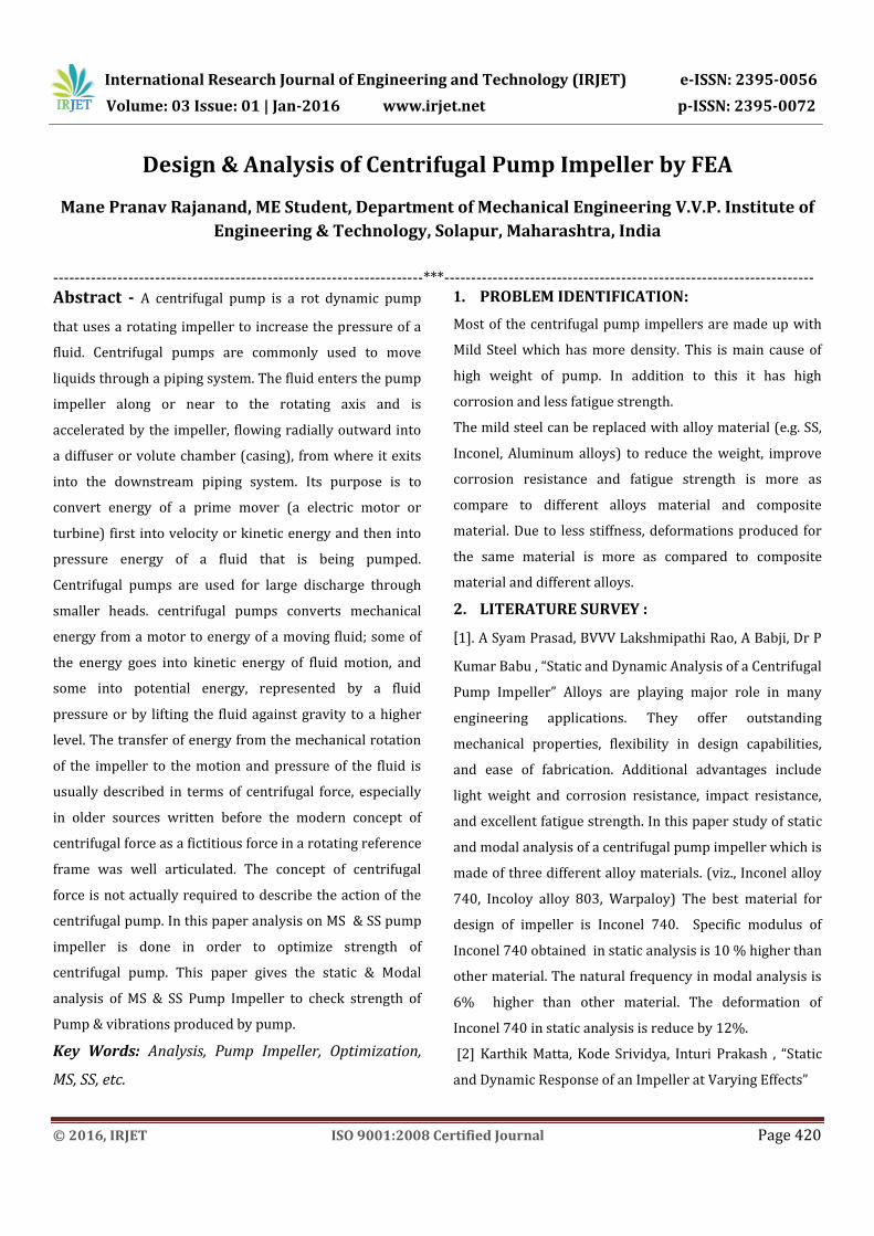
4.1 Modeling of pump impeller by using CATIA V5R20
ASSEMBLY
Fig. 1 Assembly of Centrifugal Pump
GEOMETRY
Fig. 2 Geometry of Centrifugal Pump Impeller
4.2 FEA MODEL:
MESH GENERATION:
In order to carry out a finite element analysis, the model
we are using must be divided into a number of small
pieces known as finite elements. Since the model is
divided into a number of discrete parts, FEA can be
described as a discretization technique. In simple terms, a
mathematical net or “mesh” is required to carry out a
finite element analysis. If the system under investigation is
1D in nature, we may use line elements to represent our
geometry and to carry out our analysis. If the problem can
be described in two dimensions, then a 2D mesh is
required. Correspondingly, if the problem is complex and a
3D representation of the continuum is required, then we
use a 3D mesh. Area elements can be triangular or
quadrilateral in shape. The selection of the element shape
and order is based on considerations relating to the
complexity of the geometry and the nature of the problem
being modeled. Membrane elements don’t have any
thickness. As a consequence they have no bending
stiffness; loads can only be carried in the element plane.
Plate & shell elements are used to model thin walled
regions in 3D space. The plate element is formulated
around plate theory, which assumes that the load is
carried via bending. Shell elements are used to model
shells, where there is combination of flexure & membrane
action. Plate elements are considered applicable where the
out of plane distortion is little more than the plate
thickness. There are also special elements, which facilitate
accurate modeling of thick plates. If the deflection is
greater than the plate thickness, membrane action should
be considered, and so shell elements should be used. Shell
element nodes have five degrees of freedom; the missing is
the in-plane rotational freedom (sometimes referred to as
the drilling freedom). Solid elements come in different
varieties. Axisymmetric elements are used to describe the
cross-section of an axially symmetric part. Plane strain
International Research Journal of Engineering and Technology (IRJET) e-ISSN: 2395-0056
Volume: 03 Issue: 01 | Jan-2016 www.irjet.net p-ISSN: 2395-0072
© 2016, IRJET ISO 9001:2008 Certified Journal Page 423
elements are used to describe section of long objects (such
as a shaft or wall cross-section). The strain in the out-of-
plane direction is taken to be zero, reflecting the
assumption that the strain is in one Plane stress elements
are used to describe sections of thin objects (such as a
wrench). The stress in the out-of-plane direction is taken
to be zero, reflecting the assumption that the stress is in
one plane
Fig. 3 Two dimensional elements
VOLUME MESHING:
3D elements take the form of cubes called hexahedrons
(hexes), 3D triangles called tetrahedrons (test) and 3D
wedges known as pentahedrons. Decisions on element
selection hinge on understanding the role of the element
shape and order of interpolation. Modeling with 3D-
Elements is the most flexible approach. These types of
elements are used for thick structures that have neither a
constant cross section nor an axis of symmetry. Solid
modeling will nearly always make analysis preparation
easier. Meshing and solving can take a long time;
particularly if the structure is thin-walled (large numbers
of elements are required to produce a mesh). The three
dimensional element are shown in Fig.4
Tetrahedral Hexahedral
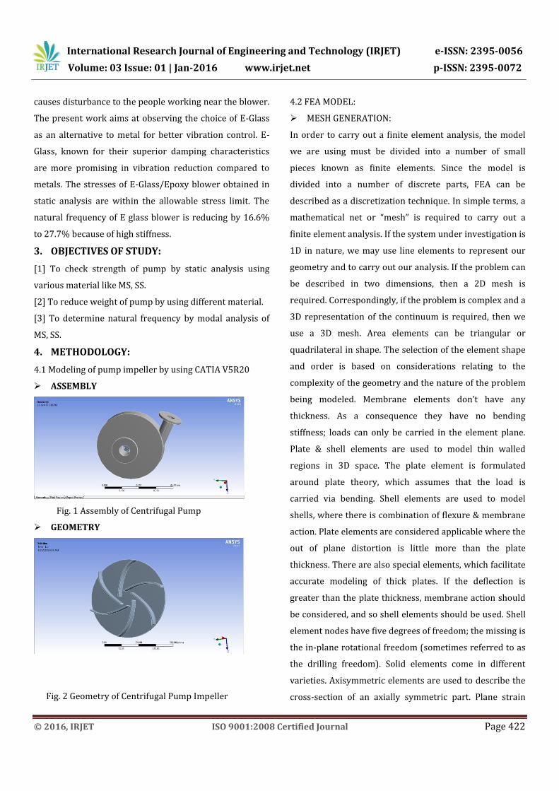
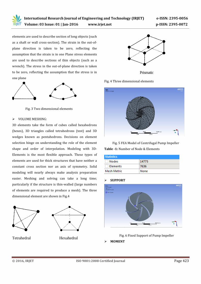
Prismatic Fig. 4 Three dimensional elements
Fig. 5 FEA Model of Centrifugal Pump Impeller
Table -1: Number of Node & Elements
SUPPORT
Fig. 6 Fixed Support of Pump Impeller
MOMENT
International Research Journal of Engineering and Technology (IRJET) e-ISSN: 2395-0056
Volume: 03 Issue: 01 | Jan-2016 www.irjet.net p-ISSN: 2395-0072
© 2016, IRJET ISO 9001:2008 Certified Journal Page 424
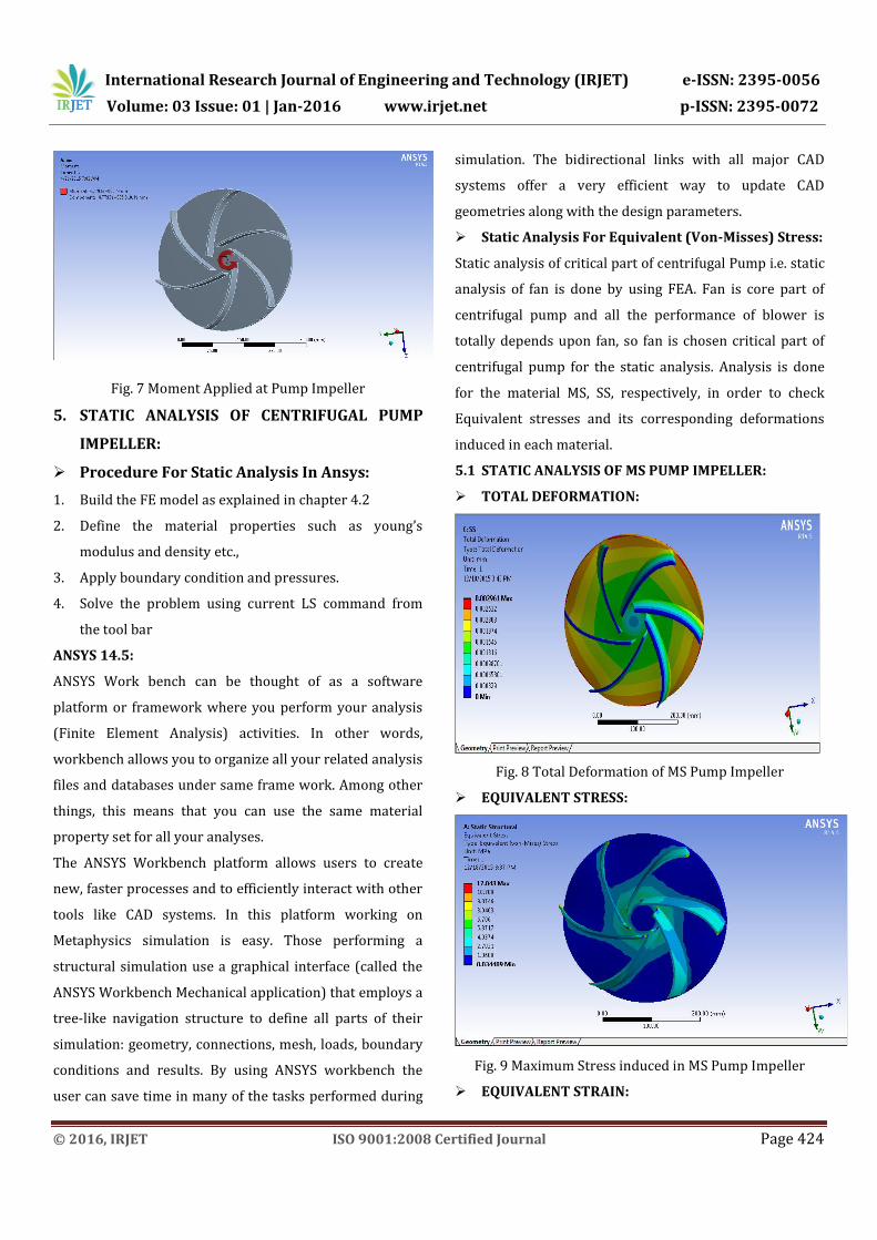
Fig. 7 Moment Applied at Pump Impeller
5. STATIC ANALYSIS OF CENTRIFUGAL PUMP
IMPELLER:
Procedure For Static Analysis In Ansys:
1. Build the FE model as explained in chapter 4.2
2. Define the material properties such as young’s
modulus and density etc.,
3. Apply boundary condition and pressures.
4. Solve the problem using current LS command from
the tool bar
ANSYS 14.5:
ANSYS Work bench can be thought of as a software
platform or framework where you perform your analysis
(Finite Element Analysis) activities. In other words,
workbench allows you to organize all your related analysis
files and databases under same frame work. Among other
things, this means that you can use the same material
property set for all your analyses.
The ANSYS Workbench platform allows users to create
new, faster processes and to efficiently interact with other
tools like CAD systems. In this platform working on
Metaphysics simulation is easy. Those performing a
structural simulation use a graphical interface (called the
ANSYS Workbench Mechanical application) that employs a
tree-like navigation structure to define all parts of their
simulation: geometry, connections, mesh, loads, boundary
conditions and results. By using ANSYS workbench the
user can save time in many of the tasks performed during
simulation. The bidirectional links with all major CAD
systems offer a very efficient way to update CAD
geometries along with the design parameters.
Static Analysis For Equivalent (Von-Misses) Stress:
Static analysis of critical part of centrifugal Pump i.e. static
analysis of fan is done by using FEA. Fan is core part of
centrifugal pump and all the performance of blower is
totally depends upon fan, so fan is chosen critical part of
centrifugal pump for the static analysis. Analysis is done
for the material MS, SS, respectively, in order to check
Equivalent stresses and its corresponding deformations
induced in each material.
5.1 STATIC ANALYSIS OF MS PUMP IMPELLER:
TOTAL DEFORMATION:
Fig. 8 Total Deformation of MS Pump Impeller
EQUIVALENT STRESS:
Fig. 9 Maximum Stress induced in MS Pump Impeller
EQUIVALENT STRAIN:

International Research Journal of Engineering and Technology (IRJET) e-ISSN: 2395-0056
Volume: 03 Issue: 01 | Jan-2016 www.irjet.net p-ISSN: 2395-0072
© 2016, IRJET ISO 9001:2008 Certified Journal Page 425
Fig. 10 Maximum Strain for MS Pump Impeller
5.2 STATIC ANALYSIS OF SS PUMP IMPELLER:
TOTAL DEFORMATION:
Fig. 11 Total Deformation of SS Pump Impeller
EQUIVALENT STRESS:
Fig. 12 Maximum Stress induced in SS Pump Impeller
EQUIVALENT STRAIN:
Fig. 13 Maximum Strain for SS Pump Impeller
6. RESULTS & DISCUSSIONS:
Table -2: Result and Discussion
Sr.
No.
Material Stress
( MPa)
Deformation
(mm)
Weight
(Kg)
1 MS 12.043 0.0028391 29.202
2 SS 11.974 0.002961 28.83
The maximum deflection induced in metallic pump fan i.e.
MS material is 0.002839 mm, which is in safe limits. Hence
based on rigidity the design is safe. The maximum induced
stress for the same material is 12.043 Mpa which is less
than the allowable stress i.e working sress by considering
factor of safety (160Gpa).Hence the design is safe based on
strength. If we compare corresponding deformation of the
material SS on above results MS material, SS having
minimum deformation therefore there are less chances of
failure of the pump fan as compare to MS materials.
Hence the strength of pump gets increased because of the
SS material. From the above result table it is clear that
weight of the SS pump (28.83Kg) fan material is minimum
as compared to MS (29.202Kg) material, hence weight of
the pump fan reduced (optimized).
7. MODAL ANALYSIS OF CENTRIFUGAL PUMP
FAN:
Procedure For Modal Analysis In ANSYS:
International Research Journal of Engineering and Technology (IRJET) e-ISSN: 2395-0056
Volume: 03 Issue: 01 | Jan-2016 www.irjet.net p-ISSN: 2395-0072
© 2016, IRJET ISO 9001:2008 Certified Journal Page 426
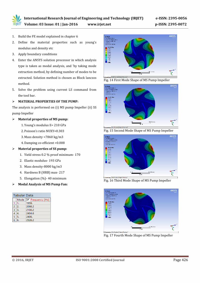
1. Build the FE model explained in chapter 6
2. Define the material properties such as young's
modulus and density etc
3. Apply boundary conditions
4. Enter the ANSYS solution processor in which analysis
type is taken as modal analysis, and 'by taking mode
extraction method, by defining number of modes to be
extracted. Solution method is chosen as Block lanczos
method.
5. Solve the problem using current LS command from
the tool bar.
MATERIAL PROPERTIES OF THE PUMP:
The analysis is performed on (i) MS pump Impeller (ii) SS
pump Impeller
Material properties of MS pump:
1. Young’s modulus E= 210 GPa
2. Poisson’s ratio NUXY=0.303
3. Mass density =7860 kg/m3
4. Damping co-efficient =0.008
Material properties of SS pump:
1. Yield stress 0.2 % proof minimum- 170
2. Elastic modulus- 193 GPa
3. Mass density-8000 kg/m3
4. Hardness B (HRB) max- 217
5. Elongation (%)- 40 minimum
Modal Analysis of MS Pump Fan:
Fig. 14 First Mode Shape of MS Pump Impeller
Fig. 15 Second Mode Shape of MS Pump Impeller
Fig. 16 Third Mode Shape of MS Pump Impeller
Fig. 17 Fourth Mode Shape of MS Pump Impeller
International Research Journal of Engineering and Technology (IRJET) e-ISSN: 2395-0056
Volume: 03 Issue: 01 | Jan-2016 www.irjet.net p-ISSN: 2395-0072
© 2016, IRJET ISO 9001:2008 Certified Journal Page 427
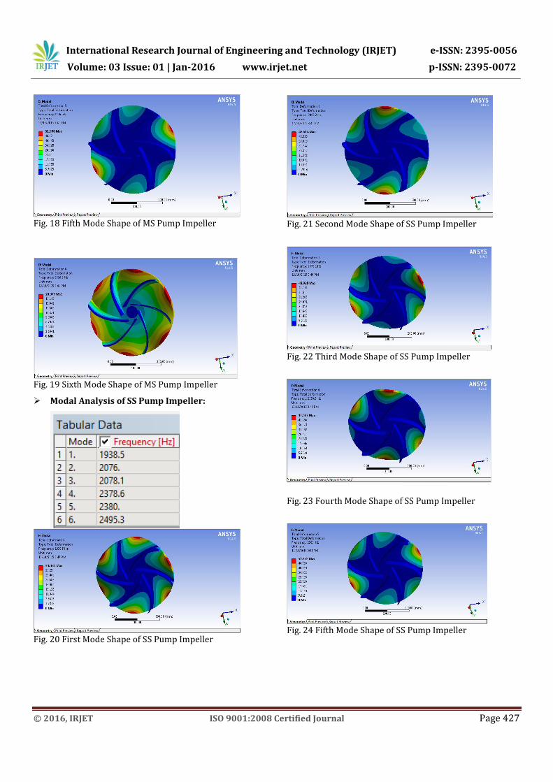
Fig. 18 Fifth Mode Shape of MS Pump Impeller
Fig. 19 Sixth Mode Shape of MS Pump Impeller
Modal Analysis of SS Pump Impeller:
Fig. 20 First Mode Shape of SS Pump Impeller
Fig. 21 Second Mode Shape of SS Pump Impeller
Fig. 22 Third Mode Shape of SS Pump Impeller
Fig. 23 Fourth Mode Shape of SS Pump Impeller
Fig. 24 Fifth Mode Shape of SS Pump Impeller
International Research Journal of Engineering and Technology (IRJET) e-ISSN: 2395-0056
Volume: 03 Issue: 01 | Jan-2016 www.irjet.net p-ISSN: 2395-0072
© 2016, IRJET ISO 9001:2008 Certified Journal Page 428
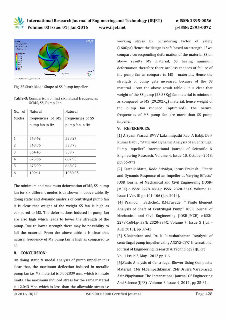
Fig. 25 Sixth Mode Shape of SS Pump Impeller
Table-3: Comparison of first six natural frequencies Of MS, SS, Pump Fan
The minimum and maximum deformation of MS, SS, pump
fan for six different modes is as shown in above table. By
doing static and dynamic analysis of centrifugal pump fan
it is clear that weight of the weight SS fan is high as
compared to MS. The deformations induced in pump fan
are also high which leads to lower the strength of the
pump. Due to lower strength there may be possibility to
fail the material. From the above table it is clear that
natural frequency of MS pump fan is high as compared to
SS.
8. CONCLUSION:
On doing static & modal analysis of pump impeller it is
clear that, the maximum deflection induced in metallic
pump fan i.e. MS material is 0.002839 mm, which is in safe
limits. The maximum induced stress for the same material
is 12.043 Mpa which is less than the allowable stress i.e
working stress by considering factor of safety
(160Gpa).Hence the design is safe based on strength. If we
compare corresponding deformation of the material SS on
above results MS material, SS having minimum
deformation therefore there are less chances of failure of
the pump fan as compare to MS materials. Hence the
strength of pump gets increased because of the SS
material. From the above result table-2 it is clear that
weight of the SS pump (28.83Kg) fan material is minimum
as compared to MS (29.202Kg) material, hence weight of
the pump fan reduced (optimized). The natural
frequencies of MS pump fan are more than SS pump
impeller.
9. REFERENCES:
[1] A Syam Prasad, BVVV Lakshmipathi Rao, A Babji, Dr P
Kumar Babu , “Static and Dynamic Analysis of a Centrifugal
Pump Impeller” International Journal of Scientific &
Engineering Research, Volume 4, Issue 10, October-2013,
pp966-971
[2] Karthik Matta, Kode Srividya, Inturi Prakash , “Static
and Dynamic Response of an Impeller at Varying Effects”
IOSR Journal of Mechanical and Civil Engineering (IOSR-
JMCE) e-ISSN: 2278-1684,p-ISSN: 2320-334X, Volume 11,
Issue 1 Ver. III pp 101-106 (Jan. 2014),
[4] Pramod J. Bachche1, R.M.Tayade “ Finite Element
Analysis of Shaft of Centrifugal Pump” IOSR Journal of
Mechanical and Civil Engineering (IOSR-JMCE) e-ISSN:
2278-1684,p-ISSN: 2320-334X, Volume 7, Issue 3 (Jul. -
Aug. 2013), pp 37-42
[5] S.Rajendran and Dr. K Purushothaman “Analysis of
centrifugal pump impeller using ANSYS-CFX” International
Journal of Engineering Research & Technology (IJERT)
Vol. 1 Issue 3, May - 2012 pp 1-6
[6].Static Analysis of Centrifugal Blower Using Composite
Material 1Mr M.Sampathkumar, 2Mr.Dsvsra Varaprasad,
3Mr.Vijaykumar The International Journal Of Engineering
And Science (IJES) , Volume 3 Issue 9, 2014 , pp 25-31 ,
No. of
Modes
Natural
frequencies of MS
pump fan in Hz
Natural
frequencies of SS
pump fan in Hz
1 543.42 538.27
2 543.86 538.73
3 564.45 559.7
4 675.86 667.93
5 675.99 668.07
6 1094.1 1080.05