Embed Size (px)
Citation preview

International Research Journal of Engineering and Technology (IRJET) e-ISSN: 2395 -0056
Volume: 03 Issue: 06 | June-2016 www.irjet.net p-ISSN: 2395-0072
© 2016, IRJET | Impact Factor value: 4.45 | ISO 9001:2008 Certified Journal | Page 646
DESIGN & ANALYSIS ON A DIESEL ENGINE BY IMPLEMENTING TANGENTIAL
GROOVES ON PISTON FOR COMBUSTION IMPROVEMENT THROUGH CFD
K.S.Karunakar1, Dr. C. Vijaya Bhaskar Reddy2, D.S. Jaheer Basha3, M. Sivaramakrishnaiah.
PG – Scholar, Department of Mechanical Engineering, SVCET (Autonomous), Chittoor, A.P, INDIA - 517127.
Professor & HOD, Department of Mechanical Engineering, SVCET (Autonomous), Chittoor, A.P, INDIA - 517127.
Assistant Professor, Department of Mechanical Engineering, SVCET (Autonomous), Chittoor, A.P, INDIA - 517127.
Assistant Professor, Department of Mechanical Engineering, SVCET (Autonomous), Chittoor, A.P, INDIA - 517127.
---------------------------------------------------------------------***---------------------------------------------------------------------Abstract - The complete combustion appears to be most
prominent way to improve the fuel efficiency and to decrease the
emission from diesel engines. The present work deals with a new
kind of piston modification. Tangential swirling grooves were made
on flat surface with centered bowl Piston for better combustion
process by increasing swirl in diesel engine. Due to the extreme
conditions inside a DI-Diesel engine, when high viscosity diesel is
injected into hot air present in the combustion chamber at the end
of TDC becomes a problem in mixing the fuel with air for proper
combustion. Experimental techniques are sometimes limited in
approaching the above mentioned problem. Alternatively, computer
simulations (like: Computational Fluid Dynamics) offer the
opportunity to carry out repetitive studies on various parameters
with clearly defined boundary conditions in order to investigate
different configurations. This project is an attempt to create
swirling motion of the compressed air in the combustion chamber
by preparing some internal grooves on the piston. Creating more
swirl motion in combustion chamber tends to make the fuel and air
as homogeneous mixture which leads to improve the combustion of
fuel. Our simulations results that the swirl generated inside the
chamber is more by using piston with tangential grooves and hence
the complete combustion is achieved along with reduced emissions.
Key Words: CFD Simulation, CATIA V5 Software, Tangential
grooves, Swirl, Tumble, Cross Tumble Coefficients.
1. INTRODUCTION
Combustion and fluid flow modelling in a diesel engine presents
one of the most challenging problems. This is due to large density
variations where, the fluid motion inside a cylinder is turbulent,
unsteady, non-stationary both spatially and temporarily. The
combustion characteristics were greatly influenced by the details of
the fuel preparation and the fuel distribution in the engine cylinder,
which was mainly controlled by the in-cylinder fluid dynamics. The
fuel injection introduces additional complexities like two phase
flows. Pollutant emissions were controlled by the turbulent fuel–air
mixing and combustion processes. A detailed understanding of these
processes is required to improve performance and reduce emissions
without compromising the fuel economy. From the literature,
several researchers performed experimental and numerical studies
towards the parameter optimization, fluid mechanics and
combustion phenomena. Combustion improvement on a direct
injection diesel engine by implementing tangential swirling grooves
by: Ritesh Kumar (121116145) Kartikpaliwal (121116139) faculty
advisor:- Dr. Rajesh Gupta [1]. A numerical investigation on swirl
generation by a helical intake port and its effects on in-cylinder flow
characteristics with axisymmetric piston bowls in a small four-valve
direct injection diesel engine. The novelty of this study is in
determining the appropriate design and orientation of the helical
port to generate high swirl. A commercial CFD software STAR-CD is
used to perform the detailed three dimensional simulations.
Preliminary studies were carried out at steady state conditions with
the helical port which demonstrated a good swirl potential and the
CFD predictions were found to have reasonably good agreement
International Research Journal of Engineering and Technology (IRJET) e-ISSN: 2395 -0056
Volume: 03 Issue: 06 | June-2016 www.irjet.net p-ISSN: 2395-0072
© 2016, IRJET | Impact Factor value: 4.45 | ISO 9001:2008 Certified Journal | Page 647
with the experimental data taken from literature. For transient cold
flow simulations, the STAR-CD code was validated with Laser
Doppler Velocimetry (LDV) experimental velocity components’
measurements available in literature [2].
C.V. Subba Reddy1,*, C. Eswara Reddy2 & K. Hemachandra Reddy
The effect of three different sizes of tangential grooves on piston
crown on the performance and emission characteristics are studied.
Brake specific energy consumption decreases and thermal efficiency
of engine slightly increases when operating on blended fuel of 20%
Cotton seed oil methyl ester (COME) and 80% diesel (20BD) than
that operating on diesel fuel [3]. Stephenson et al. conducted a
parametric study on the effects of swirl, initial turbulence, oxygen
concentration and ignition delay on fuel vaporization, mixing and
combustion process [4]. Chen et al. simulated the transient flow for
the induction stroke using STAR-CD software and observed that the
standard k- model with wall function for description of boundary
layer behaviour predict the fully turbulent flow inside the cylinder
[5]. Payri et al. [6] and Auriemma et al. [7] made in-cylinder
measurements under motoring conditions in a light duty diesel
engine equipped with a re-entrant bowl in piston combustion
chamber. Tangential and radial components of the air velocity were
obtained over a crank angle range of 90o above TDC. Estimates of
the mean motion, integral time scale and Reynolds shear stress are
also found to be comparable with the computational work.
For CI engines arrangement is made such that air inside the
cylinder is flown past the injector for proper mixing which involves
various methods to produce swirl.
Some of the common methods used are induction swirl,
divided chamber, etc.
CI engines have different shapes of piston head which
create turbulence.
1.1. SWIRL AND TUMBLE COEFFICIENTS
Both swirl and tumble flows are commonly characterized by a
dimensionless parameter employed to quantify rotational and
angular motion inside the cylinder, which are known as swirl and
tumble ratios, respectively. These values are calculated by the
effective angular speed of in-cylinder air motion divided by the
engine speed. The effective angular speed is the ratio of the angular
momentum to the angular inertia of moment. The mass center of
the charged in-cylinder air is considered as an origin for the
calculation. The three variables (swirl, sideways tumble, and normal
tumble ratio) investigated in this paper are presented in the non-
dimensional form by applying the equations as follows:
Where, Hx, Hy and Hz are the angular momentum of the in-
cylinder gas about the x-axis, y-axis and z-axis, respectively. Ix, Iy
and Iz are the moment of inertia about the x axis, y axis and z axis,
respectively. In addition, ω is the crankshaft rotation or engine
speed in the unit of rotation/minute.
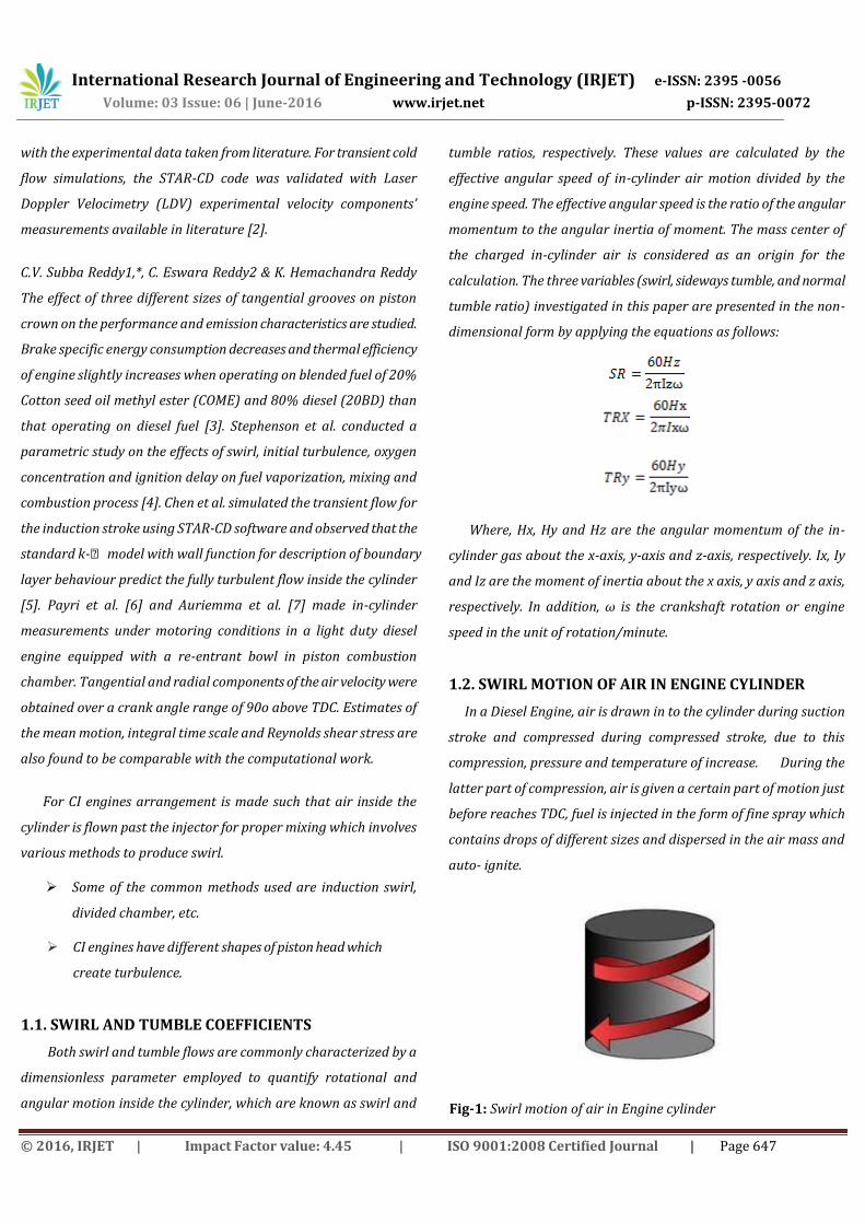
1.2. SWIRL MOTION OF AIR IN ENGINE CYLINDER
In a Diesel Engine, air is drawn in to the cylinder during suction
stroke and compressed during compressed stroke, due to this
compression, pressure and temperature of increase. During the
latter part of compression, air is given a certain part of motion just
before reaches TDC, fuel is injected in the form of fine spray which
contains drops of different sizes and dispersed in the air mass and
auto- ignite.
Fig-1: Swirl motion of air in Engine cylinder

International Research Journal of Engineering and Technology (IRJET) e-ISSN: 2395 -0056
Volume: 03 Issue: 06 | June-2016 www.irjet.net p-ISSN: 2395-0072
© 2016, IRJET | Impact Factor value: 4.45 | ISO 9001:2008 Certified Journal | Page 648
1.3. TUMBLE MOTION OF AIR IN ENGINE CYLINDER
As the piston reaches TDC the squish motion generates a
secondary flow called tumble, where rotation occurs in a
circumferential axis near the outer edge of the cavity or piston bowl
Fig-2: Tumble motion of air in engine cylinder.
1.4. AIR MOTION IN DIESEL ENGINE
In a Diesel Engine, the main problem in connection with
combustion is the intimate mixing of air and fuel and time available
for mixing and combustion is less particularly in the case of high
speed Engines. The air motion helps mixing and combustion of fuel
and improves the Engine performance and reduces emissions.
Fig-3: Air Flow with respect x, y, z-axis.
2. EXPERMENTAL DETAILS
2.1. Experimental System and Description
The experimental set up consists of single cylinder 4-stroke DI
Diesel engine with 87.5 bore diameter, 110mm stroke length, rated
speed1500 rpm, BHP/5.2KW rated power and water cooled engine.
2.2.1. LIST OF PARAMETERS INVESTIGATED ON
DIESEL ENGINE BY IMPLEMENTING WITH & WITHOUT
GROOVES THROUGH CFD SOFTWARE
Swirl ratio (v/s) Crank angle
Tumble ratio (v/s) Crank angle
Cross tumble ratio (v/s) Crank angle
Pressure (v/s) Crank angle
Temperature (v/s) crank angle
Fuel ( Mass fraction ) (v/s) Crank angle
2.2.2. EQUIPMENT/SOFTWARES USED
1. FOR DESIGNING THE PISTON
CATIA V5 SOFTWARE IS USED
2. FOR ANALYSIS OF IC ENGINE
FOR DESIGN, MESHING & ANALYSIS
ANSYS WORK BENCH
ANSYS FLUENT
2.3. SPECIFICATION OF TANGENTIAL GROOVES &
CIRCULAR BOWL ON PISTION
Table- 1: Specification of tangential grooves
S.NO TYPE BREADTH DEPTH
1. TANGENTIAL
GROOVES
7.5MM 2MM
Table -2: Specification of circular bowl
S.NO TYPE RADIUS DEPTH
1. PISTON BOWL 50MM 25MM

International Research Journal of Engineering and Technology (IRJET) e-ISSN: 2395 -0056
Volume: 03 Issue: 06 | June-2016 www.irjet.net p-ISSN: 2395-0072
© 2016, IRJET | Impact Factor value: 4.45 | ISO 9001:2008 Certified Journal | Page 649
2.4 SPECIFICATIONS OF THE ENGINE
Table -3: Specification of the engine
S.NO DESCRIPTION DETAILS
1. Type of engine Direct injection Diesel engine
2. Number of strokes 4-stroke
3. Numbers of cylinders Single cylinder
4. Bore diameter in mm 85
5. Stroke diameter in mm 110
6. Crank shaft speed in RPM 1500
7. Starting crank angle in Degrees 0
8. Crank period in Degrees 720
9. Crank angle step size 0.25
10. Crank radius in meters 0.055
11. Connecting rod length in meters 0.234
12. Piston pin offset in meters 0
13. Piston stroke cut off in meters 0
14. Minimum valve lift in meters 0.0001
Fig-4: Tangential swirling grooved piston.
2.5 EXPERIMENTAL PROCEDURE
As per engine specifications the piston is designed through
CatiaV5 software according to engine and imported the design
in Ansys Work Bench software for meshing and modeling. Then
meshing file is imported into CFD FLUENT software for analysis
of diesel engine combustion by giving engine parameters as
input and then the reading is consider for every 5Deg crank
angel is noted for piston with and without grooves.
1. Design of normal piston with and without grooves using Catiav5 software.
2. The designed piston with and without grooves are imported into CFD FLUENT software.
3. Then engine with specifications according to our requirement was imported.
4. Then we have simulated designed piston with and without grooves separately for every 5 degrees of crank angel.
5. Recorded the simulated values which were generated through software.
6. Compared the simulation results between modified tangential piston with normal piston.
3. RESULTS AND DISCUSSIONS
Experiment was conducted on ANSYS CFD Software on DI Diesel
engine, for piston with and without grooves. The main objective was
achieved by increasing the swirl motion inside the combustion
chamber for better combustion and homogeneity of air and fuel
mixture to increase the efficiency of the engine and to decrease the
emission rate so the pollution also decreases.

International Research Journal of Engineering and Technology (IRJET) e-ISSN: 2395 -0056
Volume: 03 Issue: 06 | June-2016 www.irjet.net p-ISSN: 2395-0072
© 2016, IRJET | Impact Factor value: 4.45 | ISO 9001:2008 Certified Journal | Page 650
Chart-1: swirl ratio Vs crank angel for piston with and without
grooves
The swirl ratio is observed to begin with a positive tendency, the
maximum swirl achieved around 80˚ crank angle after TDC, and
gradually decreased. During the power stroke, swirl flow again
starts increasing for piston with groove. For without grooves swirl
ratio is observed to begin with a positive tendency, Maximum swirl
is achieved around 30˚ crank angle after TDC as seen in chart-1.
Beyond this point the swirl ratio gradually decreases towards
negative swirl at the end of the suction stoke. The trend continues
into the compression stroke due to the friction at the cylinder wall.
During the power stroke, swirl flow again starts increasing for
piston without grooves as show in chart-1.
Chart-2: Tumble ratio Vs crank angel for piston with and
without grooves
The tumble ratio is observed to begin with a positive tendency,
the maximum tumble achieved around 20˚ crank angle after TDC,
and gradually decrease to negative flow. During the power stroke,
tumble flow again starts increasing for piston with groove. For
without grooves tumble ratio is observed to begin with a positive
tendency, Maximum tumble is achieved around 30˚ crank angle
after TDC as seen in chart-2. Beyond this point the tumble ratio
gradually decreases towards negative flow at the end of the suction
stoke. During the power stroke, swirl flow again starts increasing
for piston without grooves as show in chart-2.
Chart-3: Cross Tumble ratio Vs crank angel for piston with and
without grooves
The chart shows the cross tumble ratio and its variation inside
the cylinder. The maximum CT ratio for piston with grooves is
achieved around 90˚ crank angle after TDC, and starts decreasing
till the suction stroke. Again cross tumble starts increasing from
power stroke. The chart shows crosses tumble ratio for piston
without grooves and its variation inside the cylinder. The maximum
CT ratio for is achieved around 60˚crank angle after TDC, as shown
in chart and starts decreasing till the suction stroke. Again cross
tumble starts increasing from compression as well as for power
stroke as shown in chart-3.

International Research Journal of Engineering and Technology (IRJET) e-ISSN: 2395 -0056
Volume: 03 Issue: 06 | June-2016 www.irjet.net p-ISSN: 2395-0072
© 2016, IRJET | Impact Factor value: 4.45 | ISO 9001:2008 Certified Journal | Page 651
Chart--4: Pressure vs crank angel for piston with and without
grooves
The chart shows the pressure generated inside the cylinder. The
maximum pressure generated for piston with grooves is achieved
around 360˚ crank angle after TDC during power stroke then
gradually decreased. The pressure generated inside the cylinder, the
maximum pressure generated for piston without grooves is achieved
around 360˚ crank angle after TDC during power stroke then
gradually decreased as shown in chart-4.
Chart-5: Temperature vs crank angle for piston with and without
grooves.
The chart shows the temperature generated inside the cylinder.
The maximum temperature generated for piston with grooves is
achieved around 340˚ crank angle after TDC during combustion
then gradually decreased. The temperature generated inside the
cylinder. The maximum temperature generated for piston without
grooves is achieved around 340˚ crank angle after TDC during
combustion then gradually decreased as shown in chart-5.
Chart-6: fuel (mass fraction) vs crank angel for piston with and
without grooves
The chart shows the fuel mass fraction consumed inside the
cylinder. The maximum fuel mass fraction consumed for piston with
grooves is achieved around 380˚ crank angle after TDC during
combustion then remains same. The maximum fuel mass fraction
consumed for piston without grooves is achieved around 380˚ crank
angle after TDC during combustion then remains same as shown in
chart-6.
Fig-5: CFD simulation for velocity path inside the cylinder

International Research Journal of Engineering and Technology (IRJET) e-ISSN: 2395 -0056
Volume: 03 Issue: 06 | June-2016 www.irjet.net p-ISSN: 2395-0072
© 2016, IRJET | Impact Factor value: 4.45 | ISO 9001:2008 Certified Journal | Page 652
Fig-6: CFD simulation for velocity vector inside the cylinder
4. CONCLUSION
Based on the values obtained from the CFD Analysis through
diesel engine for both with and without grooves, The following
conclusion are made The varied piston geometry of tangential port
enhances the turbulence and this is due to better mixing of air-fuel,
the thermal efficiency is increased and whereas specific fuel
consumption and soot emissions are reduced. This is one of the
major compromises of the swirl flows, that are the requirement of
large inlet valve for larger suction of air flow during high engine
RPM and the requirement of smaller inlet valve for better swirl
intensity generation.so their exits an optimal ratio for both swirl,
tumble and cross tumble flows.
The performance of the engine falls beyond optimal ratios due
to the decrease in volumetric efficiency, even though, the swirl,
tumble and cross tumble intensities are very high. This study show
that in –cylinder CFD predication yield a responsible result that
allows improving the knowledge of the in-cylinder flow pattern and
characteristics during intake and compression strokes instead of
using the experimental test by practical image The NOX emissions
are reduced because of better mixing and a faster combustion
process. Swirl motion in the combustion chamber at the end of
compression stroke
The swirl, tumble and cross tumble has been increased for piston
with tangential grooves so that the better mixture of air and fuel
takes place for complete combustion.
REFERENCES
[1] Combustion improvement on a direct injection diesel engine by
implementing tangential swirling grooves by: Ritesh Kumar
(121116145) Kartikpaliwal (121116139) faculty advisor:- Dr.
Rajesh Gupta.
[2] Vamshi Krishna Dawat, Ganesan Venkitachalam, Influence of a
High-Swirling Helical Port with Axisymmetric Piston Bowls on In-
Cylinder Flow in a Small Diesel Engine, 2016-04-05, Technical Paper
2016-01-0587.
[3] C.V. Subba Reddy1,*, C. Eswara Reddy2 & K. Hemachandra
Reddy Effect of Tangential Grooves on Piston Crown of Diesel
Engine with Preheated Cotton Seed Oil.
[4] Stephenson, P.W., Clay baker, P.J., Rutland, C.T., Modelling the
effects of intake generated turbulence and resolved flow structures
on combustion in direct injection diesel engine. SAE Paper No.
960634.
[5] Chen, A., A. Veshagh, S. Wallace, Intake flow predictions of a
transparent direct injection diesel engine. SAE Paper No. 981020.
[6] Payri, F., J. Benajes, X. Margeo, A .Gil, CFD modelling of the in-
cylinder flow in direct injection diesel engine. Computers & Fluids;
vol (33), 2004, p. 995–1021.
[7] Auriemma, M., F.E. Corcione, R. Macchioni, G. Valentino,
Interpretation of air motion in re-entrant bowl in-piston engine by
estimating Reynolds stresses. SAE Paper No. 980482.
Author (s) E-mail:
1. [email protected] ;
3. [email protected] ;