Embed Size (px)
Citation preview

Design and Additive Manufacture for Flow Chemistry Supplementary Information
Andrew J. Capel, Steve Edmondson, Steven D. R. Christie, Ruth D. Goodridge, Richard Bibb and Matthew Thurstans
Table of Contents 1. Experimental Details………………………………………………………………………...…1
1.1 Data Analysis……………………………………………………...………….1
1.2 Computer Aided Design……………………………………………………...2
1.3 Additive manufacturing equipment…………………………………………..2
2. Reactors………………………………………………………………………………………...2
2.1 RD1…………………………………………………………………………...2
2.2 RD2…………………………………………………………………………...2
2.3 RD3…………………………………………………………………………...3
2.4 RD4…………………………………………………………………………...3
2.5 RD5…………………………………………………………………………...3
2.6 RD6……………………………………………………………………….…..4
2.7 RD7…………………………………………………………………….……..4
2.8 RD8……………………………………………………………………..…….5
2.9 RD9……………...............................................................................................5
3. Chemical Syntheses………………………………………………………………………...….5
3.1 Oxidation of Aldehydes to Methyl Esters………………………………...….5
3.2 Procedure for the Production of Sudan 1 Dye………………………….…….8
4. Solvent Compatibility Data………………………………………………………….…………9
5. Build Resolutions………………………………………………………………………………9
General Considerations
1.1 Data Analysis
All 1H and 13C spectra were measured at 400 and 100 MHz respectively using a Bruker DPX 400
MHz spectrometer. The solvent used for NMR spectroscopy was chloroform-d1 (δ 7.26, 1H; δ 77.0, 13C) using TMS as the internal reference. Chemical shifts are reported in ppm and J values are
reported in Hz. All flow reactions were carried out using a FlowSyn continuous flow system. All
chromatographic manipulations used silica gel as the adsorbent. Reactions were monitored using
TLC on aluminium backed plates with Merck TLC 60 F254 silica gel. TLC visualised by UV light at a
Electronic Supplementary Material (ESI) for Lab on a ChipThis journal is © The Royal Society of Chemistry 2013

wavelength of 254 nm, or stained by exposure to an ethanolic solution of vanillin (acidified with
concentrated sulphuric acid), followed by charring where appropriate. Purification by column
chromatography using Apollo ZEOprep 60/ 40-63 micron silica gel.
1.2 Computer Aided Design
CAD drawings were produced using the commercially available software NX 7.5 (Siemens Industry
Software), and converted to .STL file format for visualisation in MiniMagics 2.0 (Materialise).
1.3 Additive manufacturing equipment
Selective Laser Melting (SLM) – SLM parts were produced using a Renishaw AM250, Renishaw
MTT 100 or a Realizer SLM 50
Stereolithography Apparatus (SLA) – SL parts were produced using a 3D Systems Viper si2 SLA
system.
Multi-Jet Modelling (MJM) – MJM parts were produced using a 3D Systems ProJet 3000Plus 3D
Printer.
Selective Laser Sintering (SLS) – SLS parts were produced using an EOS FORMIGA P 100 and an
EOS EOSINT P 390 system.
Fused Deposition Modelling (FDM) – FDM parts were produced using a Stratasys Dimension 3D
Modelling Printer.
2. Reactors
2.1 RD1
Reactor design 1 was manufactured via FDM from acrylonitrile butadiene styrene (ABS) to external
dimensions of approximately 150x30x30mm. The reactor had two inlets joining at a t-piece connected
to an outlet by a continuous tube of length 510 mm, diameter 3 mm and a total volume of 3.6 mL,
contained within a wall thickness of 5 mm. The flow path has a split-and-recombine (SAR) mixer
geometry.
1 cm
Electronic Supplementary Material (ESI) for Lab on a ChipThis journal is © The Royal Society of Chemistry 2013
2.2 RD2
Reactor design 2 was manufactured via SL from Accura 60 resin to external dimensions of
approximately 70x50x50mm. The reactor had a single inlet connected to an outlet by a continuous
tube of length 3300 mm, diameter 3 mm and a total volume of 23mL.
2.3 RD3
Reactor design 3 was manufactured via SL from Accura 60 resin to external dimensions of
approximately 70x50x50mm. The reactor had two inlets joined at an internal t-piece, connected to an
outlet by a continuous tube of length 3300 mm, diameter 3 mm and a total volume of 23mL.
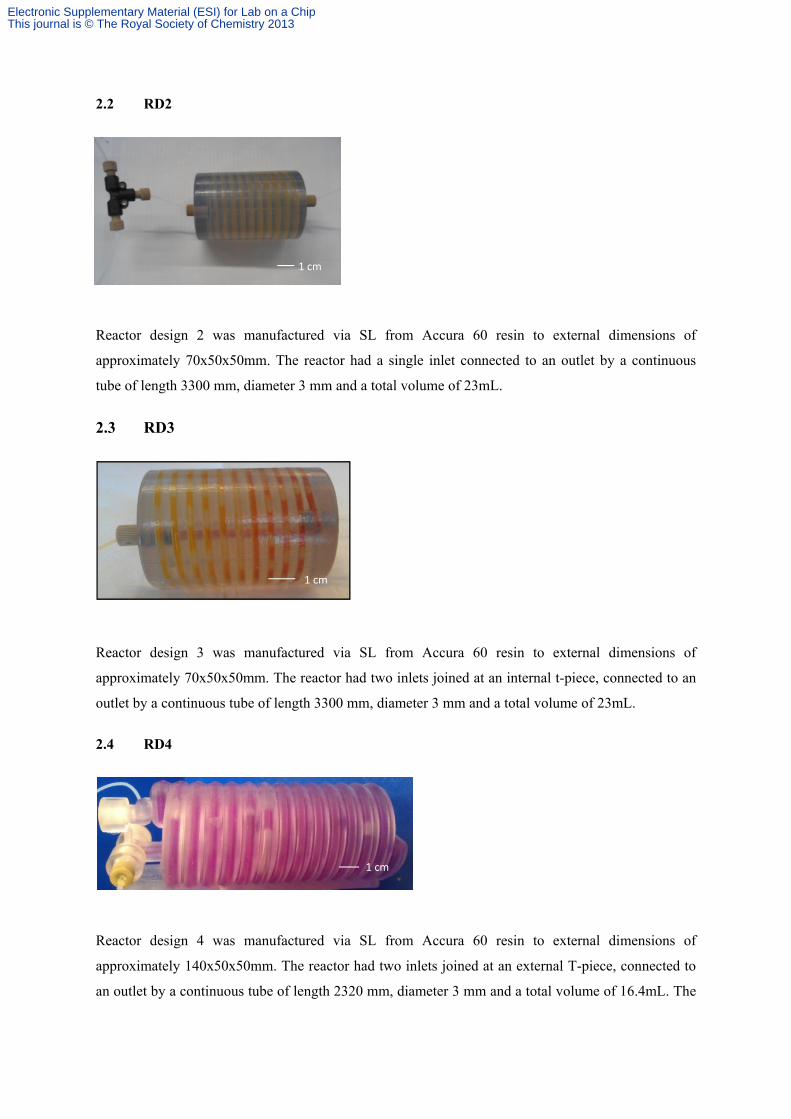
2.4 RD4
Reactor design 4 was manufactured via SL from Accura 60 resin to external dimensions of
approximately 140x50x50mm. The reactor had two inlets joined at an external T-piece, connected to
an outlet by a continuous tube of length 2320 mm, diameter 3 mm and a total volume of 16.4mL. The
1 cm
1 cm
1 cm
Electronic Supplementary Material (ESI) for Lab on a ChipThis journal is © The Royal Society of Chemistry 2013
flow path has an initial split-and-recombine (SAR) mixer geometry (internal, not visible), followed by
a continuous tube wrapped around the outside.
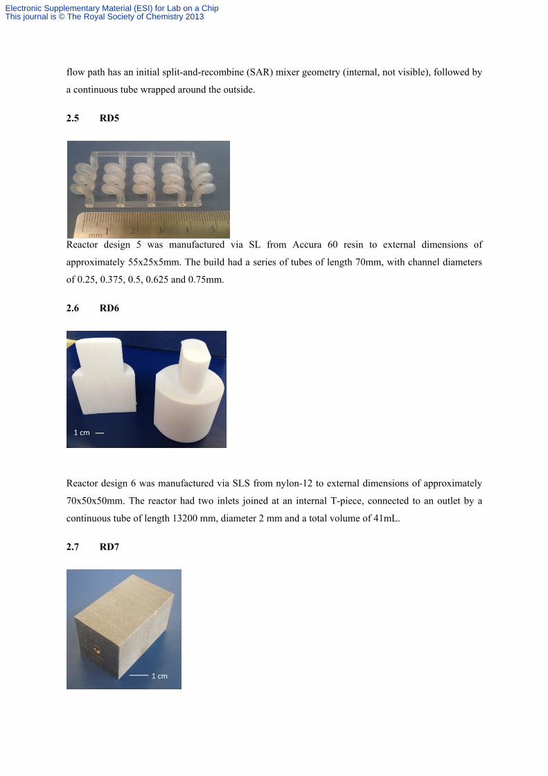
2.5 RD5
Reactor design 5 was manufactured via SL from Accura 60 resin to external dimensions of
approximately 55x25x5mm. The build had a series of tubes of length 70mm, with channel diameters
of 0.25, 0.375, 0.5, 0.625 and 0.75mm.
2.6 RD6
Reactor design 6 was manufactured via SLS from nylon-12 to external dimensions of approximately
70x50x50mm. The reactor had two inlets joined at an internal T-piece, connected to an outlet by a
continuous tube of length 13200 mm, diameter 2 mm and a total volume of 41mL.
2.7 RD7
1 cm
1 cm
Electronic Supplementary Material (ESI) for Lab on a ChipThis journal is © The Royal Society of Chemistry 2013
Reactor design 7 was manufactured via SLM from stainless steel to external dimensions of
approximately 55x30x30mm. The reactor had a single inlet connected to an outlet by a continuous
tube of length 300 mm, diameter 3 mm and a total volume of 2.1mL.
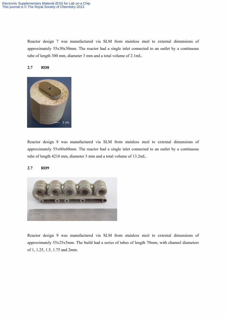
2.7 RD8
Reactor design 8 was manufactured via SLM from stainless steel to external dimensions of
approximately 55x60x60mm. The reactor had a single inlet connected to an outlet by a continuous
tube of length 4210 mm, diameter 3 mm and a total volume of 13.2mL.
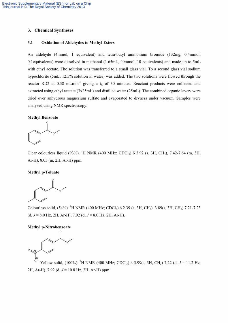
2.7 RD9
Reactor design 9 was manufactured via SLM from stainless steel to external dimensions of
approximately 55x25x5mm. The build had a series of tubes of length 70mm, with channel diameters
of 1, 1.25, 1.5, 1.75 and 2mm.
1 cm
Electronic Supplementary Material (ESI) for Lab on a ChipThis journal is © The Royal Society of Chemistry 2013
O
O
N
O
O
O
O
3. Chemical Syntheses
3.1 Oxidation of Aldehydes to Methyl Esters
An aldehyde (4mmol, 1 equivalent) and tetra-butyl ammonium bromide (132mg, 0.4mmol,
0.1equivalents) were dissolved in methanol (1.65mL, 40mmol, 10 equivalents) and made up to 5mL
with ethyl acetate. The solution was transferred to a small glass vial. To a second glass vial sodium
hypochlorite (5mL, 12.5% solution in water) was added. The two solutions were flowed through the
reactor RD2 at 0.38 mLmin-1 giving a tR of 30 minutes. Reactant products were collected and
extracted using ethyl acetate (3x25mL) and distilled water (25mL). The combined organic layers were
dried over anhydrous magnesium sulfate and evaporated to dryness under vacuum. Samples were
analysed using NMR spectroscopy.
Methyl Benzoate
Clear colourless liquid (93%). 1H NMR (400 MHz; CDCl3) δ 3.92 (s, 3H, CH3), 7.42-7.64 (m, 3H,
Ar-H), 8.05 (m, 2H, Ar-H) ppm.
Methyl p-Toluate
Colourless solid, (54%). 1H NMR (400 MHz; CDCl3) δ 2.39 (s, 3H, CH3), 3.89(s, 3H, CH3) 7.21-7.23
(d, J = 8.0 Hz, 2H, Ar-H), 7.92 (d, J = 8.0 Hz, 2H, Ar-H).
Methyl p-Nitrobenzoate
Yellow solid, (100%). 1H NMR (400 MHz; CDCl3) δ 3.99(s, 3H, CH3) 7.22 (d, J = 11.2 Hz,
2H, Ar-H), 7.92 (d, J = 10.8 Hz, 2H, Ar-H) ppm.
O
O
Electronic Supplementary Material (ESI) for Lab on a ChipThis journal is © The Royal Society of Chemistry 2013
Br
O
O
O
O
N
O
O
OO
O
O
Methyl p-Bromobenzoate
White solid, (100%). 1H NMR (400 MHz; CDCl3) δ 3.92(s, 3H, CH3) 7.57-7.59 (m, 2H, Ar-H), 7.89-
7.91 (m, 2H, Ar-H).
Methyl 3-phenylpropionoate
Colourless Liquid, (100%). 1H NMR (400 MHz; CDCl3) δ 2.61-2.66(t, J = 4 Hz, 2H, CH2), 2.80-2.81
(t, J = 4 Hz, 2H, CH2), 7.11-7.54 (m, 5H, Ar-H) ppm.
Methyl 3-Nitrobenzoate
Yellow solid, (99%). 1H NMR (400 MHz; CDCl3) δ 4.00(s, 3H, CH3), 7.45-7.69 (t, J = 7.8 Hz, 1H,
Ar-H), (dt, J = 1.4, 7.9 Hz, 1H, Ar-H), 7.92 (ddd, J = 0.8, 2.0, 8.0 Hz, 2H, Ar-H), 8.87-8.89 (t, J = 5.6
Hz, 1H, Ar-H) ppm.
Methyl trans-cinnamate
Yellow solid, (17%). 1H NMR (400 MHz; CDCl3) δ 3.83(s, 3H, CH3), 6.70-6.72 (d, J = 7.6 Hz, 1H,
CH), 6.74-6.76 (d, J = 7.6 Hz, 1H, CH), 7.26-7.60 (m, 5H, Ar-H) ppm.
Electronic Supplementary Material (ESI) for Lab on a ChipThis journal is © The Royal Society of Chemistry 2013
O
O
O
N
O
O
O
O
Methyl isobutyrate
Colourless oil, (100%). 1H NMR (400 MHz; CDCl3) δ 1.18-1.20(d, J = 5.2 Hz, 6H, CH3), 2.57-2.62
(sept, J = 6.7 Hz, 1H, CH), 4.40 (s, 3H, CH3) ppm.
Methyl anisate
Yellow Oil, (5%). 1H NMR (400 MHz; CDCl3) δ 3.90(s, 3H, CH3), 6.52-6.53 (dd, J = 1.6, 3.6 Hz, 1H,
CH), 7.18-7.19 (dd, J = 1.6, 3.6 Hz, 1H, CH), 7.58-7.59 (dd, J = 1.6, 3.6 Hz, 1H, CH3) ppm.
Methyl o-Nitrobenzoate
Yellow liquid, (56%). 1H NMR (400 MHz; CDCl3) δ 3.92 (s, 3H, CH3), 7.64-7.92 (m, 4H, Ar-H)
ppm.
Methyl o-Iodobenzoate
Yellow liquid, (22%). 1H NMR (400 MHz; CDCl3) δ 3.93 (s, 3H, CH3), 7.12-7.98 (m, 4H, Ar-H)
ppm.
Electronic Supplementary Material (ESI) for Lab on a ChipThis journal is © The Royal Society of Chemistry 2013

N
N
O
H
Procedure for the Production of Sudan 1 Dye
A solution of aniline (0.2mL, 0.204g, 2.19mmol), hydrochloric acid (10M.,0.35mL), water (2mL) and
N,N-dimethylformamide (4mL) was prepared and pumped at 0.195 mL/min-1 . A solution of sodium
nitrite (0.75g, 10.9mmol), water (4mL) and N,N-dimethylformamide (2mL) was prepared and
pumped at 0.195 mLmin-1. The two streams intercepted at a t-piece and were pumped together at 0.39
mL/min-1 through SLA reactor RD3, giving a residence time of 30 minutes. After 30 minutes the
stream was intercepted by a solution of β-napthol (0.3g, 1.04mmol), sodium hydroxide solution (10%,
6 mL), water (3mL) and N,N-dimethylformamide (3mL) being pumped at 0.39 mL/min-1 giving a
residence time of 15 minutes. Reactant products were collected and extracted using diethyl ether
(3x25mL) and water (25mL). The combined organic layers were dried over anhydrous magnesium
sulfate and evaporated to dryness under vacuum. Samples were analysed using NMR spectroscopy.
Red Solid, (17%). 1H NMR (400 MHz; CDCl3) δ 6.87-6.89 (d, J = 8.0, 1H, Ar-H), 7.11-7.78 (m, 9H,
Ar-H), 8.56-8.58 (d, J = 8.0 Hz, 1H, Ar-H), 16.28 (s, 1H, OH) ppm.
Procedure for the persulfate-iodide reaction
A solution of 0.5M potassium iodide (20mL, 1.66g) was prepared and pumped at rates ranging from
18-40 mLmin-1 through inlet A. A second solution of 0.01M potassium persulfate (20mL, 0.05g),
0.01M sodium thiosulfate (10mL, 0.02g) and 5 drops of starch indicator was prepared and pumped at
rates ranging from 18-40mLmin-1 through inlet B. The inlets were joined at a t-piece before passing
into SLA reactor RD4. The flow stream was visually monitored, with the time being recorded at
which the reaction changed colour from colourless to a vibrant blue. The reaction conditions were
repeated using commercially available PTFE tubing as the flow path.
Electronic Supplementary Material (ESI) for Lab on a ChipThis journal is © The Royal Society of Chemistry 2013
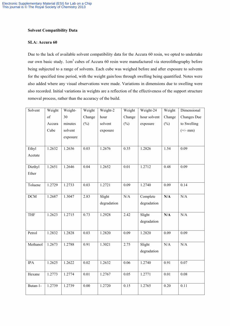
Solvent Compatibility Data
SLA: Accura 60
Due to the lack of available solvent compatibility data for the Accura 60 resin, we opted to undertake
our own basic study. 1cm3 cubes of Accura 60 resin were manufactured via stereolithography before
being subjected to a range of solvents. Each cube was weighed before and after exposure to solvents
for the specified time period, with the weight gain/loss through swelling being quantified. Notes were
also added where any visual observations were made. Variations in dimensions due to swelling were
also recorded. Initial variations in weights are a reflection of the effectiveness of the support structure
removal process, rather than the accuracy of the build.
Solvent Weight
of
Accura
Cube
Weight-
30
minutes
solvent
exposure
Weight
Change
(%)
Weight-2
hour
solvent
exposure
Weight
Change
(%)
Weight-24
hour solvent
exposure
Weight
Change
(%)
Dimensional
Changes Due
to Swelling
(+/- mm)
Ethyl
Acetate
1.2632 1.2636 0.03 1.2676 0.35 1.2826 1.54 0.09
Diethyl
Ether
1.2651 1.2646 0.04 1.2652 0.01 1.2712 0.48 0.09
Toluene 1.2729 1.2733 0.03 1.2721 0.09 1.2740 0.09 0.14
DCM 1.2687 1.3047 2.83 Slight
degradation
N/A Complete
degradation
N/A N/A
THF 1.2623 1.2715 0.73 1.2928 2.42 Slight
degradation
N/A N/A
Petrol 1.2832 1.2828 0.03 1.2820 0.09 1.2820 0.09 0.09
Methanol 1.2673 1.2788 0.91 1.3021 2.75 Slight
degradation
N/A N/A
IPA 1.2625 1.2622 0.02 1.2632 0.06 1.2740 0.91 0.07
Hexane 1.2773 1.2774 0.01 1.2767 0.05 1.2771 0.01 0.08
Butan-1- 1.2739 1.2739 0.00 1.2720 0.15 1.2765 0.20 0.11
Electronic Supplementary Material (ESI) for Lab on a ChipThis journal is © The Royal Society of Chemistry 2013
ol
To determine whether any material leaching had occurred into the solvent, we weighed the contents of
the vial both before and after the experiment. The vial weights were equal, both before and after the
experiments, showing that there was no detectable level of leaching into the solvent from the Accura
60 solvent.
SLM: Stainless Steel
Stainless steel is a chemically robust material due to the stable metal oxide layer coating its surface.
Full solvent stability data can be found on the Cole-Palmer website
(http://www.coleparmer.co.uk/Chemical-Resistance). Physical observations of the part during use
showed no sign of any chemical degradation of the parts, including removal of any partially sintered
steel particles from the surface.
SLS: NYLON-12
The amide linkage on NYLON-12 makes it chemically susceptible to a range of chemicals typically
including strong acids and nucleophiles. No chemistry was undertaken using NYLON-12 parts and
therefore no leaching effects have been observed. Full solvent stability data can be found on the Cole-
Palmer website (http://www.coleparmer.co.uk/Chemical-Resistance).
FDM: ABS
ABS is chemically susceptible to a range of reagents typically including strong acids and
nucleophiles, as well as a range of general organic solvents. It is also prone to large degrees of
swelling in these conditions. Full solvent stability data can be found on the Cole-Palmer website
(http://www.coleparmer.co.uk/Chemical-Resistance). No chemistry was undertaken using NYLON-
12 parts and therefore no leaching effects have been observed.
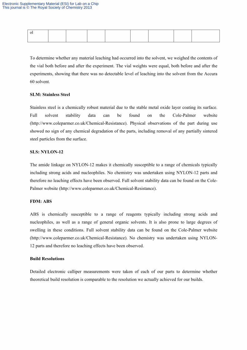
Build Resolutions
Detailed electronic calliper measurements were taken of each of our parts to determine whether
theoretical build resolution is comparable to the resolution we actually achieved for our builds.
Electronic Supplementary Material (ESI) for Lab on a ChipThis journal is © The Royal Society of Chemistry 2013
Reactor
Design
AM
Manufacturing
Process
Description of
Measurement
Taken
Measurement
Taken (mm)
Corresponding
CAD
Measurement
(mm)
Resolution
(+/- mm)
RD1 FDM External tube
circumference
(cylinder)
9.92 10.00 -0.08
External tube
width
(hexagonal)
9.08 9.00 +0.08
RD2 SLA Circumference 52.04 52.00 +0.04
Length 75.06 75.00 +0.06
RD3 SLA Circumference 52.06 52.00 +0.06
Length 75.03 75.00 +0.03
RD4 SLA External tube
circumference
(cylinder)
14.95 15.00 -0.05
External tube
width
(hexagonal)
9.47 9.50 -0.03
Base plate
width
27.46 27.50 -0.04
RD5 SLA Tube
circumference
2.99 3.00 -0.01
RD6 SLS Reactor
circumference
62.12 62.00 +0.12
Entrance port
width
20.29 20.00 +0.29
Electronic Supplementary Material (ESI) for Lab on a ChipThis journal is © The Royal Society of Chemistry 2013
Entrance port
length
40.07 40.00 +0.07
RD7 SLM
(Renishaw
250)
Reactor length 49.91 50.00 -0.09
Reactor width 30.35 30.25 -0.10
RD8 SLM
(Renishaw
250)
Reactor
circumference
62.22 62.00 +0.22
Entrance port
width
20.12 20.00 +0.12
Entrance port
length
40.14 40.00 +0.14
RD9 SLM
(Realizer 50)
Tube 1
internal
diameter
1.77 1.75 +0.02
Tube 2
internal
diameter
1.52 1.50 +0.02
Tube 3
internal
diameter
1.25 1.25 0
Support frame
width
3.49 3.50 -0.01
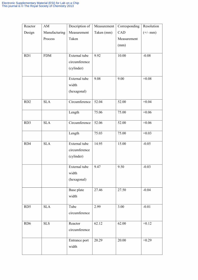
FDM parts were built within +/- 0.1mm of the exact designed dimensions of the built parts,
demonstrating a significant improvement over theoretical build resolutions.
SLA parts were built within +/-0.05mm of the exact designed dimensions of the built parts,
demonstrating the scope of accurate builds possible when using SLA.
Electronic Supplementary Material (ESI) for Lab on a ChipThis journal is © The Royal Society of Chemistry 2013

SLS parts were built within +/-0.3mm of the exact designed dimensions of the built parts, showing
that theoretical build resolutions are often not achieved without precise build parameter optimisation
for each individual part.
SLM parts were built within +/-0.22mm of the exact designed dimensions of the built parts using the
Renishaw AM 250, however using the Realizer 50 resolution was improved dramatically to +/-
0.02mm
Electronic Supplementary Material (ESI) for Lab on a ChipThis journal is © The Royal Society of Chemistry 2013