Embed Size (px)
Citation preview
Abstract—in this paper, an improved metal-backed RFID
tag antenna is presented. The proposed antenna is designed to
operate at 915 MHz with MONZA3 RFID chip. Ground
material effect is studied for different material cases. The
designed antenna achieves very good radiation characteristics
with directive main lobe, and good impedance matching, which
makes it suitable for metal-objects RFID applications. Then
testing the antenna with seven different soil samples taken
from Riyadh city following results show the different electrical
properties of seven different soil samples taken from Riyadh
city. Moreover, the results illustrate the effect of the water
content effect on the soil properties. The measurements are
done using DAK kit provided by SPEAG Company. The
measurements are done over two frequency bands, the first
from 850 MHz to 950 MHz, while the second one from 1 GHz
to 5 GHz.
Index Terms— RFID, Antenna, Radio-Frequency
Identification, CSTMWS, Modelling and Simulation.
I. INTRODUCTION
n this paper, the applicants are investigating a novel
approach that will address the application of Radio
Frequency Identification (RFID) technology to several areas
of importance to the Kingdom of Saudi Arabia. RFID
technology has a very high potential application in different
sectors of oil and mining industry including exploration and
management of resources. The proposed research will focus
on several challenging issues related to RFID technology
and its implementation with focus on both device
development and design and improving their RF range. It
presents the theory of electromagnetic waves propagation
through sands, soils, rocks, etc. Our focus is on evaluating
and selecting RFID systems for harsh environments with
emphasis on the design and testing of different novel reader
and tag antennas and investigating their performance and
improving read ranges of low-frequency RFID systems.
Prototyping and testing of RFID reader are also planned
together with investigating its properties through software
simulation and measurements in harsh environments, like
performing the tests in dusty atmosphere, very high
operating temperature leaving the device for extended
periods of time in this environment and repeating the test.
The project is of strategic interest to the Kingdom because
Manuscript received February 18, 2019; revised April 8, 2019. This
work was supported by NSTIP strategic technologies program number 12-
ELE2462-02 in the Kingdom of Saudi Arabia.; e-mail: [email protected].
A Telba king Saud University, Riyadh 11421, P.O.Box 800 Kingdom of
Saudi Arabia.
Abdel-Razik Sebak ECE Department Concordia University Montreal,
QC, Canada king [email protected]
of the importance of oil and mining service industry and
utility companies and the potential of RFID technology. In
addition, results of this project are applicable to any other
area where it is necessary to detect and locate buried objects,
or "to see" tagged objects through media such as concrete.
II. LITERATURE REVIEW
A. Review Stage
Radio Frequency Identification (RFID) technology is an
emerging technology for a broad spectrum of applications
including managing goods, tracking the movement of tools,
equipment, people, animals or even anti-counterfeiting [1]-
[7]. The use of RFID technology improves safety in a
variety of applications such as tracking location of miners
and in personal protective equipment. RFID retrieves data
stored on a tag wirelessly. It comprises of a tag, a reader,
and a host computer with data management software [8]-
[10]. A full RFID system consists of three major
components [3]
a) RFID tags (transponders),
b) RFID readers (transceivers),
c) Application software (Data processing subsystem).
Tags are attached to the objects so that every RFID enabled
object has its own unique identification (ID) number. Object
identification is performed by information exchange
between tag and reader via radio transmissions at
low/high/ultra-high frequencies (LF/HF/UHF). The tags can
be either passive or active based on their power mechanism.
Passive tag harvests the energy from the reader antenna
radiating near field and responds to reader query by
modulating the backscattered signal. They are cheap and
long life as compared to active tags that use internal
batteries as source of power. However, active tags can
operate at longer ranges and typically have a larger capacity,
higher data transfer speeds and increased read/write
capability [3]. RFID enabled sites will monitor activities and
inventory in real time.
Ultra-high frequency (UHF) and microwave based RFID
systems have been developed to be operated at relatively
longer ranges using radiating fields between reader and tag
antennas [11]-[12]. Use of higher frequencies has several
advantages like high speeds and comparatively longer
ranges. However, their performance gets severely hampered
by the presence of dielectric or metallic materials present in
the propagation channel. UHF RFID systems found
applications in item-level tagging in retailing industry and
other applications including short range wireless
communication, material characterization, and various
modulated scattering probe techniques [13]-[14].
Design and Analysis of a Metal-Backed RFID
Tag Antenna for Oil Mining
A. Telba Member, IAENG, Ayman Elboushi 1, K. Jamil and Abdel-Razik Sebak
I
Proceedings of the World Congress on Engineering 2019 WCE 2019, July 3-5, 2019, London, U.K.
ISBN: 978-988-14048-6-2 ISSN: 2078-0958 (Print); ISSN: 2078-0966 (Online)
(revised on 20 May 2019) WCE 2019
The Kingdom of Saudi Arabia’s oil and mining sectors
are of “strategic importance” to the Kingdom economy.
Around the world, oil and mining industries are taking
advantage of the quick expansion of computers and
microelectronics in many development activities including
exploration methods, through production, and marketing
[15]. RFID is a very powerful and useful technology to
improve production, operational and financial results of both
oil and mining industries, while continuing to meet the
expected demand for energy. The use of RFID in the Oil and
mining industries is very well accepted in the transportation
and distribution network [16]. Considering the harsh
environment in the oil and mining fields, RFID tags have the
advantage of withstanding harsh conditions, can work in
extreme weather conditions, and remain operable long after
bar codes would have been washed or worn away. It is
expected that operators of planned new oil fields in the
Kingdom will make use of the RFID technology to adhere to
inspection protocols of critical components and follow
safety and security guidelines and codes. These two sectors
and related petrochemical industries, for example SABIC
and other Corporations, are the main sources of prosperity
for Saudi’s families [17]. As well, the manufacturing sector,
the high tech industries and utilities are all dependent, in
some way, on the oil, mining and related industries.
RuBee RFID technology works at low frequencies, in
100KHz range, using long wave magnetic induction
coupling mechanism between the reader and tag.[21-22].
RuBee standard enables full-duplex communications and
can be used to form a network of sensors. Majority of
energy radiated from reader to the tag lies in magnetic field
[21]. This allows reading around metals and liquids, as well
as through rocks because they are non-magnetic materials.
As a matter of fact, magnetic materials are rare in nature.
Longer battery life is achieved due to the use of slower
clocks at the tags. Longer read-range is related to the
performance of the reader's antenna [22]. A RuBee tag
contains a battery, integrated circuit with associated
memory, crystal for timing and an antenna. The tag’s
antenna depends on the application as well as operating
frequency.
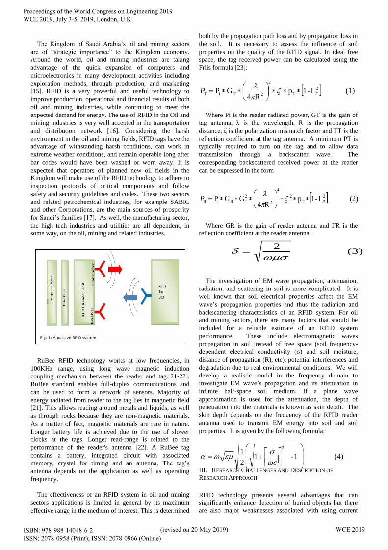
The effectiveness of an RFID system in oil and mining
sectors applications is limited in general by its maximum
effective range in the medium of interest. This is determined
both by the propagation path loss and by propagation loss in
the soil. It is necessary to assess the influence of soil
properties on the quality of the RFID signal. In ideal free
space, the tag received power can be calculated using the
Friis formula [23]:
Where Pi is the reader radiated power, GT is the gain of
tag antenna, λ is the wavelength, R is the propagation
distance, ζ is the polarization mismatch factor and ΓT is the
reflection coefficient at the tag antenna. A minimum PT is
typically required to turn on the tag and to allow data
transmission through a backscatter wave. The
corresponding backscattered received power at the reader
can be expressed in the form
Where GR is the gain of reader antenna and ΓR is the
reflection coefficient at the reader antenna.
The investigation of EM wave propagation, attenuation,
radiation, and scattering in soil is more complicated. It is
well known that soil electrical properties affect the EM
wave’s propagation properties and thus the radiation and
backscattering characteristics of an RFID system. For oil
and mining sectors, there are many factors that should be
included for a reliable estimate of an RFID system
performance. These include electromagnetic waves
propagation in soil instead of free space (soil frequency-
dependent electrical conductivity (σ) and soil moisture,
distance of propagation (R), etc), potential interferences and
degradation due to real environmental conditions. We will
develop a realistic model in the frequency domain to
investigate EM wave’s propagation and its attenuation in
infinite half-space soil medium. If a plane wave
approximation is used for the attenuation, the depth of
penetration into the materials is known as skin depth. The
skin depth depends on the frequency of the RFID reader
antenna used to transmit EM energy into soil and soil
properties. It is given by the following formula:
III. RESEARCH CHALLENGES AND DESCRIPTION OF
RESEARCH APPROACH
RFID technology presents several advantages that can
significantly enhance detection of buried objects but there
are also major weaknesses associated with using current
Fig. 1: A passive RFID system
(1) -1pR4
GP 2
T
2
2TiT TP
(2) -1pR4
GGP 2
T
2
4
2
2
TRiR RP
(3) 2
(4) 1- 12
12
Proceedings of the World Congress on Engineering 2019 WCE 2019, July 3-5, 2019, London, U.K.
ISBN: 978-988-14048-6-2 ISSN: 2078-0958 (Print); ISSN: 2078-0966 (Online)
(revised on 20 May 2019) WCE 2019
RFID technology in the mining and oil industry. Most of the
weaknesses are due to the harsh environment and limitation
of reading ranges [24]. Another barrier to RFID
implementation is the antenna performance degradation due
to soil conditions that will limit the reading range and may
cause anon-reliable wireless communication link. The
applicants will consider some of these problems and analyze
several proposed solutions to improve the overall
performance.
1. Study of the propagation properties into soils
The attenuation properties, associated with equations (3)
and (4), in media like cement-concrete, soil, rock, mud, sand
at frequencies of LF-UHF ranges are not well understood
and publications that describe EM wave propagations
underground, under rocks or under cement concrete are rare.
Attenuation and scattering are some of the properties that
determine limitations of low-frequency RFID systems.
Ground's properties can be described in terms of its
permittivity and permeability. For soil and rocks, the
permittivity is dominantly controlled by the distribution and
content of water. The permeability is dominantly controlled
by the distribution and content of iron. These parameters can
greatly impact signal propagation and attenuation. One of
the challenges will be to accurately simulate, model and test
the propagation through different environments such as soil,
rock, mud, and cement concrete.
The first step is to study the attenuation properties and
parameters that affect, attenuate or enhance the propagation
of electromagnetic signals into soils at LF and UHF
frequencies. This part also includes numerical and
experimental characterizations of the EM field propagation
underground, under sands, rocks and concrete with
embedded metallic frames which will enable us to better
understand the conditions that affect signal propagation.
2. Antennas for RFID applications in Mining, Oil and/or
Utility Industries
We focus on the development of different antennas for
both RFID tags and readers including range measurement
techniques, and concentrated on application to mining, oil
and utility industries and analyze various practical aspects
such as its sensitivity to fabrication process and packaging.
A main task of our investigation will concentrate on
studying the range distance and its effect on the selection,
design, shape and geometrical parameters of reader
antennas. To improve read orientation sensitivity, we will
consider design tags with multiple antennas as well looking
into the effect of polarization diversity to minimize such
limitation issues. The following tasks will be carried out
first through simulation and once optimized will be
fabricated and tested. The analysis will be extended to active
tags [3] and tags operating at other frequencies.
3. Testing the exiting RFID systems in a harsh
environment
In this part of the project, the applicants will test the
existing low-frequency RFID devices in harsh
environments, like performing the tests in dusty atmosphere,
very high operating temperature leaving the device for
extended periods of time in this environment and repeating
the test. The applicants will test the RFID devices in a
normal environment, then compare and analyze it with the
performance in a harsh environment. In this part of the
project, we will use a number of RFID readers that will be
purchased and investigate techniques to improve their
accuracy to minimize readings error, such as duplicate or
miss reads.
4. Building the reader antenna
A series of antennas (to be used as reader antenna) with
different shapes and sizes will be designed and tested to
understand their behaviors in terms of transmitting signals
and power levels over the horizontal and vertical directions.
Furthermore, exhaustive comparison with existing
regulations and standards should be performed to avoid any
potential accident while activating tags on detonators. This
part includes theoretical examination of designs of very
efficient and electrically small-size reader antennas for a
125/134 kHz frequency range and other RFID frequency
bands investigating and optimizing a number of their
characteristics including data transfer rate, cost, radiation
efficiency, and side-lobe level to reduce interference.
Simulations of radiation pattern, input impedance, and
antenna power coupling of the reader antenna will also be
performed and compared with available data. Due to the
constraints of frequency of operation as well as the desire to
have the smallest size as possible, the designed antenna
must typically be a physically large but electrically small
antenna. An optimal reader antenna type and size will be
determined based on EM simulation and following
analytical expressions. The built antenna radiation pattern
will be measured in the lab and compared to the analytical
expressions and numerical simulations. Another challenge
will be to determine the size of the reader's antenna. Low
frequency signals «150 kHz) can propagate, under some
conditions, through large distance of soil and rock, but
require a very large antenna (hundreds of meters). The
advantage of using, for example, a loop antenna is that it
covers a much larger surface area. The disadvantage is that
the large antenna is not practical to be built and tested. A
more practical approach is to build a smaller antenna which
has diameter of less than 10 meters. If the antenna is placed
at a large distance from the reader, instead of direct
connection to the reader IC, a transmission line should be
used and losses must be accounted for.
6. Regulations and standards
In order to use RFID technology to detect detonators,
strict regulations must be applied and rigorous procedures
followed to avoid any accident [25]. Therefore, the
applicants must define precisely the levels of powers to be
applied to tags fixed on detonators, regardless of the reading
distance. The applicants plan to work closely with The
Saudi Geological Survey (SGS): http://www.sgs.org.sa/
and other government agencies on these issues.
Proceedings of the World Congress on Engineering 2019 WCE 2019, July 3-5, 2019, London, U.K.
ISBN: 978-988-14048-6-2 ISSN: 2078-0958 (Print); ISSN: 2078-0966 (Online)
(revised on 20 May 2019) WCE 2019

7. Detection of buried objects
One important aspect of this project is to detect tags
before the blast as well as to detect tags attached to misfired
detonators after the blast. The applications of that system
include detection of not only explosive devices and
materials buried underground but also objects buried under
various materials such as mud, water, snow, cement
concrete with embedded metallic frames, rocks, etc.
8. Proposed tag antenna structure
The schematic diagram of the proposed antenna is shown in
Fig. 1. The antenna, basically, consists of two elliptical
patches printed on a semi-flexible substrate
RT6010® with relative permittivity
I
TABLE I. THE PROPOSED ANTENNA DIMENSIONS IN (MM).
The input impedance of the proposed tag antenna is
shown in Fig. 3. The differential port of the antenna is
intended to be connected to MONZA3 chip [6], which has
an input impedance of (32-j216) ohm. The design
parameters of the antenna are optimized using CSTMWS in
order to have an impedance close to the complex conjugate
of the chip impedance. The simulated impedance of the
antenna is found to be around (40+j216) ohm. The reflection
coefficient of the proposed antenna (S11) is calculated using
the formula shown in Eq.1 [3]. To investigate the impact of
different metallic-object materials on the antenna
performance, three different ground planes (annealed
copper, aluminum, and iron) are considered in the
simulations. As illustrated in Fig. 3, there are some
deterioration in the antenna matching of using aluminum
and iron instead of copper. The former behavior can be
accounted to the conductivity reduction of the ground plane.
The proposed antenna exhibits an impedance bandwidth
of 3 MHz starts from 913 MHz to 916 MHz with a center
frequency of 915 MHz (in case of copper ground plane).
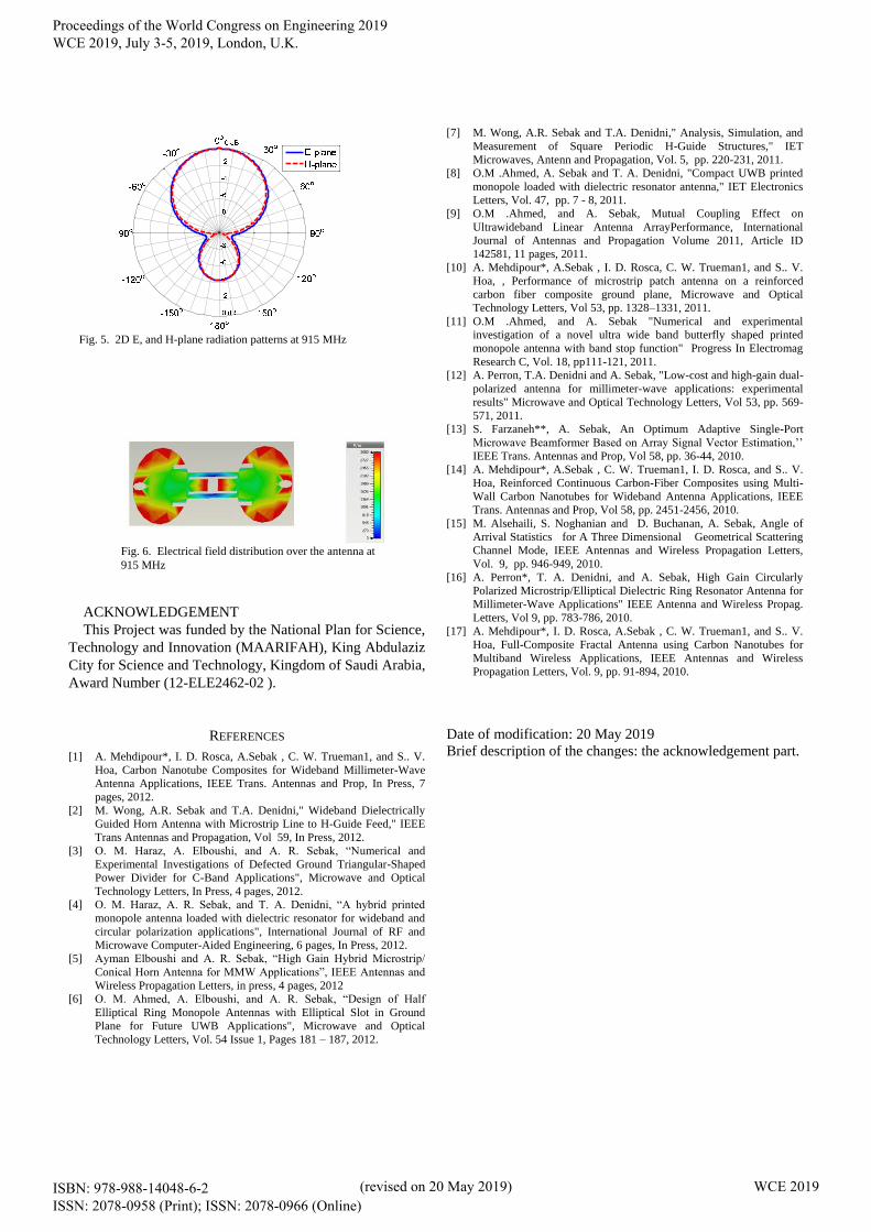
Both 2D E (X-Z) and H-plane (Y-Z) radiation patterns at
915 MHz are introduced in Fig. 4. The proposed antenna
exhibits a broadside directional pattern, with a directivity of
4.89 dBi as shown in Fig. 5. The electrical field distribution
over the antenna at 915 MHz is presented in Fig. 6. It can be
noticed that there are fast variation of the electrical fields
near the edges of the elliptical patches, which are
responsible for radiating behavior.
Fig. 2. Schematic diagram for the proposed tag antenna
Fig. 4. Reflection coefficient (S11) of the tag antenna
over different ground plane materials
Fig. 3. Input impedance of the proposed antenna
(real and imaginary).
Proceedings of the World Congress on Engineering 2019 WCE 2019, July 3-5, 2019, London, U.K.
ISBN: 978-988-14048-6-2 ISSN: 2078-0958 (Print); ISSN: 2078-0966 (Online)
(revised on 20 May 2019) WCE 2019
ACKNOWLEDGEMENT
This Project was funded by the National Plan for Science,
Technology and Innovation (MAARIFAH), King Abdulaziz
City for Science and Technology, Kingdom of Saudi Arabia,
Award Number (12-ELE2462-02 ).
REFERENCES
[1] A. Mehdipour*, I. D. Rosca, A.Sebak , C. W. Trueman1, and S.. V.
Hoa, Carbon Nanotube Composites for Wideband Millimeter-Wave
Antenna Applications, IEEE Trans. Antennas and Prop, In Press, 7
pages, 2012.
[2] M. Wong, A.R. Sebak and T.A. Denidni," Wideband Dielectrically
Guided Horn Antenna with Microstrip Line to H-Guide Feed," IEEE
Trans Antennas and Propagation, Vol 59, In Press, 2012.
[3] O. M. Haraz, A. Elboushi, and A. R. Sebak, “Numerical and
Experimental Investigations of Defected Ground Triangular-Shaped
Power Divider for C-Band Applications", Microwave and Optical
Technology Letters, In Press, 4 pages, 2012.
[4] O. M. Haraz, A. R. Sebak, and T. A. Denidni, “A hybrid printed
monopole antenna loaded with dielectric resonator for wideband and
circular polarization applications", International Journal of RF and
Microwave Computer-Aided Engineering, 6 pages, In Press, 2012.
[5] Ayman Elboushi and A. R. Sebak, “High Gain Hybrid Microstrip/
Conical Horn Antenna for MMW Applications”, IEEE Antennas and
Wireless Propagation Letters, in press, 4 pages, 2012
[6] O. M. Ahmed, A. Elboushi, and A. R. Sebak, “Design of Half
Elliptical Ring Monopole Antennas with Elliptical Slot in Ground
Plane for Future UWB Applications", Microwave and Optical
Technology Letters, Vol. 54 Issue 1, Pages 181 – 187, 2012.
[7] M. Wong, A.R. Sebak and T.A. Denidni," Analysis, Simulation, and
Measurement of Square Periodic H-Guide Structures," IET
Microwaves, Antenn and Propagation, Vol. 5, pp. 220-231, 2011.
[8] O.M .Ahmed, A. Sebak and T. A. Denidni, "Compact UWB printed
monopole loaded with dielectric resonator antenna," IET Electronics
Letters, Vol. 47, pp. 7 - 8, 2011.
[9] O.M .Ahmed, and A. Sebak, Mutual Coupling Effect on
Ultrawideband Linear Antenna ArrayPerformance, International
Journal of Antennas and Propagation Volume 2011, Article ID
142581, 11 pages, 2011.
[10] A. Mehdipour*, A.Sebak , I. D. Rosca, C. W. Trueman1, and S.. V.
Hoa, , Performance of microstrip patch antenna on a reinforced
carbon fiber composite ground plane, Microwave and Optical
Technology Letters, Vol 53, pp. 1328–1331, 2011.
[11] O.M .Ahmed, and A. Sebak "Numerical and experimental
investigation of a novel ultra wide band butterfly shaped printed
monopole antenna with band stop function" Progress In Electromag
Research C, Vol. 18, pp111-121, 2011.
[12] A. Perron, T.A. Denidni and A. Sebak, "Low-cost and high-gain dual-
polarized antenna for millimeter-wave applications: experimental
results" Microwave and Optical Technology Letters, Vol 53, pp. 569-
571, 2011.
[13] S. Farzaneh**, A. Sebak, An Optimum Adaptive Single-Port
Microwave Beamformer Based on Array Signal Vector Estimation,’’
IEEE Trans. Antennas and Prop, Vol 58, pp. 36-44, 2010.
[14] A. Mehdipour*, A.Sebak , C. W. Trueman1, I. D. Rosca, and S.. V.
Hoa, Reinforced Continuous Carbon-Fiber Composites using Multi-
Wall Carbon Nanotubes for Wideband Antenna Applications, IEEE
Trans. Antennas and Prop, Vol 58, pp. 2451-2456, 2010.
[15] M. Alsehaili, S. Noghanian and D. Buchanan, A. Sebak, Angle of
Arrival Statistics for A Three Dimensional Geometrical Scattering
Channel Mode, IEEE Antennas and Wireless Propagation Letters,
Vol. 9, pp. 946-949, 2010.
[16] A. Perron*, T. A. Denidni, and A. Sebak, High Gain Circularly
Polarized Microstrip/Elliptical Dielectric Ring Resonator Antenna for
Millimeter-Wave Applications" IEEE Antenna and Wireless Propag.
Letters, Vol 9, pp. 783-786, 2010.
[17] A. Mehdipour*, I. D. Rosca, A.Sebak , C. W. Trueman1, and S.. V.
Hoa, Full-Composite Fractal Antenna using Carbon Nanotubes for
Multiband Wireless Applications, IEEE Antennas and Wireless
Propagation Letters, Vol. 9, pp. 91-894, 2010.
Date of modification: 20 May 2019
Brief description of the changes: the acknowledgement part.
Fig. 5. 2D E, and H-plane radiation patterns at 915 MHz
Fig. 6. Electrical field distribution over the antenna at
915 MHz
Proceedings of the World Congress on Engineering 2019 WCE 2019, July 3-5, 2019, London, U.K.
ISBN: 978-988-14048-6-2 ISSN: 2078-0958 (Print); ISSN: 2078-0966 (Online)
(revised on 20 May 2019) WCE 2019


![Localization of Compact Circularly Polarized RFID Tag ...Localization of Compact Circularly Polarized RFID Tag ... tion using sparsely distributed passive RFID tags. ... [12]DIGIAMPAOLO,](https://img.pdfslide.net/doc/110x75/5e79d0688d24f90ca522e9fc/localization-of-compact-circularly-polarized-rfid-tag-localization-of-compact.jpg)