Embed Size (px)
Citation preview
Progress In Electromagnetics Research, Vol. 120, 1–16, 2011
DESIGN AND ANALYSIS OF A MULTI-CARRIER TX-RXSYSTEM BASED ON RATIONALLY SYNCHRONIZEDOSCILLATORS FOR LOCALIZATION APPLICATIONS
M. Fernandez*, S. Ver Hoeye, C. Vazquez, G. Hotopan,R. Camblor, and F. Las Heras
Area of Signal Theory and Communications, Department of ElectricalEngineering, University of Oviedo, Campus de Viesques, EdificioPolivalente s/n, Modulo 8, Planta 1, E-33203, Gijon, Spain
Abstract—In this work, a novel multi-carrier Tx-Rx system based onrationally synchronized oscillators to be used in RF-source localizationapplications is presented. The Tx subsystem is composed by tworationally synchronized oscillators, with different operation frequency,which share the reference signal. This signal is transmitted togetherwith the one generated by the oscillators. In the Rx subsystem, thereference signal is provided by an oscillator which is synchronized withthe received reference signal. According to the simulation results,with the proposed approach, the determination of the relative phasevariation suffered by the transmitted signals, due to the propagationchannel, can be achieved with an error less than 0.6◦. It is also shownthat the dynamic response of the system can be optimized by properlyselecting the operation point of all oscillators.
1. INTRODUCTION
During the last years, several techniques for RF-based indoorlocalization systems [1–4] have been developed. Some of them arebased on the determination of the direction of arrival (DoA) [5–7] or the time of arrival (ToA) [8], but in both cases, multipatheffects reduce their efficiency. In order to overcome this drawback,other techniques consider the strength of the received signals [9] anduse triangulation methods in order to determine the position of thetransmitters. Although these methods present a good accuracy, agreat effort has been carried out for developing numerical techniques
Received 15 July 2011, Accepted 25 August 2011, Scheduled 27 August 2011* Corresponding author: Miguel Fernandez Garcia ([email protected]).
2 Fernandez et al.
to improve it [8, 10]. From the hardware point of view, the targetpositioning accuracy can be enhanced if information about bothmagnitude and phase of several transmitted signals is available in thereceivers [11].
The most common topologies used in order to design coherentmulti-carrier transmitters and receivers with a common phase referenceare based on Phase-Locked Loops (PLL) [12]. PLL-based systems havedesirable characteristics such as their dynamical response, capabilityto determine phase variations with high accuracy, and good frequencyand phase stability. However, when several carrier signals are needed,the complexity and the cost of these systems greatly increases with thenumber of used PLLs.
A novel approach to design a Tx-Rx multicarrier system withcapability of phase variation determination, based on RationallySynchronized Oscillators (RSO) [13, 14], is described in this paper.The RSO is a very compact and low cost circuit, since it is based on asingle transistor and a reduced number of components. The proposedsystem provides the same advantages as a PLL-based system [13], withlower complexity and cost.
A coherent two carrier system is designed and analyzed. Onthe one hand, the transmitter subsystem is composed by two RSOcircuits synchronized with a common reference signal with frequencyfr = 5GHz. Each RSO generates a carrier signal with differentfrequency, fo, 3
5= 3 GHz, fo, 3
4= 3.75GHz. These two signals are
transmitted along with a sample of the reference signal. As the twooscillators are injection-locked with the same reference signal, thetransmitted signals have a fixed known phase relation which is reachedthrough their synchronizing harmonic components.
On the other hand, the receiver topology is similar to thetransmitter one. It is based on two RSO which are identical to thoseused in the transmitter. In this case, their reference signal is providedby an oscillator that is synchronized with the received reference signal.The relative phase variation suffered by the transmitted signals, dueto the arbitrary propagation channel, will be calculated by comparingthe phase of the received signals and the phase of the signals generatedin the Rx RSOs.
The described system is analyzed through nonlinear harmonicbalance and envelope transient techniques based on the use of auxiliarygenerators [13, 15–17]. The advantages of using an additional oscillatorin the Rx subsystem will be shown, and the main error sources will beidentified. Finally, it will be demonstrated that the relative phasevariation of the transmitted signals can be calculated with an errorless than 0.6◦.
Progress In Electromagnetics Research, Vol. 120, 2011 3
2. DESIGN AND ANALYSIS OF THE TRANSMITTER
2.1. Topology
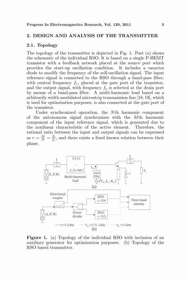
The topology of the transmitter is depicted in Fig. 1. Part (a) showsthe schematic of the individual RSO. It is based on a single P-HEMTtransistor with a feedback network placed at the source port whichprovides the start-up oscillation condition. It includes a varactordiode to modify the frequency of the self-oscillation signal. The inputreference signal is connected to the RSO through a band-pass filter,with central frequency fr, placed at the gate port of the transistor,and the output signal, with frequency fo is selected at the drain portby means of a band-pass filter. A multi-harmonic load based on aarbitrarily width modulated microstrip transmission line [18, 19], whichis used for optimization purposes, is also connected at the gate port ofthe transistor.
Under synchronized operation, the Nth harmonic componentof the autonomous signal synchronizes with the Mth harmoniccomponent of the input reference signal, which is generated due tothe nonlinear characteristic of the active element. Therefore, therational ratio between the input and output signals can be expressedas r = M
N = fo
fr, and there exists a fixed known relation between their
phase.
Zo
f0
Idealfilter
(V ,f , )AG AG AG
IAG
(f ,P , )r r r
frZ ( f
f =Mf
L
r
)
( )L
Multi-harmonicload
(a)
Directionalcoupler
Powerdivider
f =5 GHzr
RSOr =3/51
RSOr =3/42
(f ,P , )r r r
Three-bandantenna
f =3.75 GHz3/4 f =3 GHz3/5
(b)
0
Z 0
φ
φ
φ
Figure 1. (a) Topology of the individual RSO with inclusion of anauxiliary generator for optimization purposes. (b) Topology of theRSO based transmitter.
4 Fernandez et al.
Figure 1(b) shows the topology of the multi-carrier transmitter,composed by two RSOs synchronized with the same reference signal,with frequency fr = 5GHz, power Pr and phase φr. This signalis provided to each oscillator by means of a power divider whichis designed in order to ensure that the reference signal availableat the input is identical for all RSOs. Since the frequency of theself-oscillation signal of each RSO is different, fo, 3
5= 3 GHz and
fo, 34
= 3.75GHz, the rational relation ri must also be different:
r1 =f
o, 35fr
= MN1
= 35 , r2 =
fo, 34fr
= MN2
= 34 . In this way, it is
possible to generate two signals with non-harmonical frequency ratioand with a known phase relation with the reference signal, as shownin Equations (A1) to (A8) in Appendix A. Together with the outputsignals of the RSOs, a sample of the reference signal is transmitted bymeans of a three port multi-band antenna [20–23].
Note that the proposed architecture is easily scalable, by simplyadding the desired number of RSO circuits, with the proper rotationnumber ri = M
Ni.
2.2. Design and Analysis of the Individual RSO
The frequency fo, MN
, the quality factor QL and the harmonic contentof the circuit are imposed by means of an harmonic balance basedoptimization process in which several parameters of the circuit aremodified in order to satisfy the non-perturbation condition of theauxiliary generator [16, 17], which operates with frequency fAG = fo, M
N,
amplitude VAG = V 1o and phase φAG. The synchronization bandwidth
is maximized through the control of the harmonic content of theRSO [14], i.e., the amplitudes of the Nth harmonic component of theself-oscillation signal, V N
o and the Mth harmonic component of thereference signal, V M
r , with phase φNMN
and φMr , respectively. The use
of this technique provides a locking range large enough to ensure thatthe circuit has practical applications with low reference signal power,and for high synchronization orders, with M, N > 2.
The locking range is calculated by tracing the synchronizationloci of the circuit. This trace represents all the solutions in whichthe frequencies of the Nth harmonic component of the self-oscillationsignal and the Mth harmonic component of the reference signal arethe same and, thus, the phase difference ∆φ = φM
r −φNMN
is constant in
time. Assuming that φMr is constant, the loci is obtained carrying
out a sweep in φ1MN
= φAG between 0◦ and 360N
◦, calculating for
Progress In Electromagnetics Research, Vol. 120, 2011 5
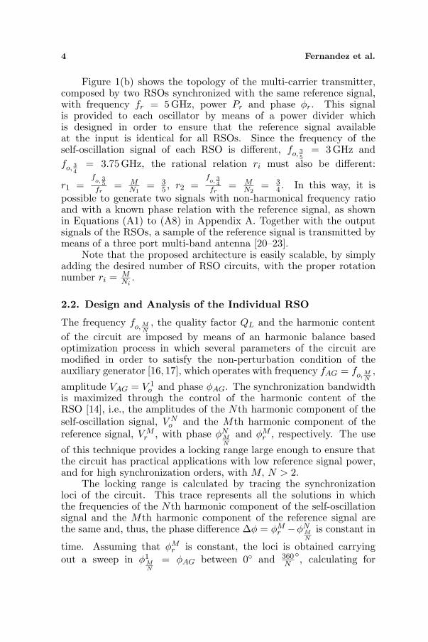
each point of the sweep the values of fAG = fo and VAG = V 1o
for which the non-perturbation condition of the auxiliary generatoris satisfied [16, 17]. Fig. 2 shows the synchronization loci of the twoRSO with r1 = 3
5 and r2 = 34 , obtained with a power value of the
reference signal Pr = −10 dBm. It is also represented the phase relation∆φ = φAG between the first harmonic component of the self-oscillationsignal of each RSO and the reference signal. Note that the maximumphase variation is 360
Ni
◦, since the first harmonic component of the self-oscillation signal is being considered. Continuous traces correspondto stable solutions, while unstable ones are depicted with dashed line.The stability of the solutions has been determined through the envelopetransient technique [16, 17].
2.3. Operation Point of the RSOs
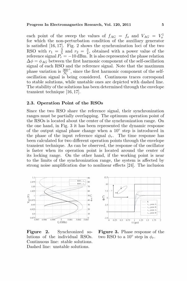
Since the two RSO share the reference signal, their synchronizationranges must be partially overlapping. The optimum operation point ofthe RSOs is located about the center of the synchronization range. Onthe one hand, in Fig. 3 it has been represented the dynamic responseof the output signal phase change when a 10◦ step is introduced inthe phase of the input reference signal φr. The time response hasbeen calculated for two different operation points through the envelopetransient technique. As can be observed, the response of the oscillatoris faster when its operation point is located around the center ofits locking range. On the other hand, if the working point is nearto the limits of the synchronization range, the system is affected bystrong noise amplification due to nonlinear effects [24]. The inclusion
4.997 4.998 4.999 5 5.001 5.002 5.0030.875
0.9
0.925
0.95
0.975
1
1.025
1.05
1.075
1.1
fr (GHz)
VA
G(V
)
0
10
20
30
40
50
60
70
80
90
RSO , r /
RSO , r2 3/4
AG
(º)
φ
51 3
Figure 2. Synchronized so-lutions of the individual RSOs.Continuous line: stable solutions.Dashed line: unstable solutions.
0 0.25 0.5 0.75 1 1.25 1.5 1.75 2-2.5
0
2.5
5
7.5
10
12.5
t ( s)
(º)
f
V
A
B
r
r , point A3/5
r , point B3/5
r , point A3/4
r , point B3/4
φ
φ
µ
Figure 3. Phase response of thetwo RSO to a 10◦ step in φr.
6 Fernandez et al.
of a varactor diode as a part of the feedback networks allows theself-oscillation signal frequency tuning, which means that the centerfrequency of each synchronization loci can be slightly modified, in orderto overlap their center points.
2.4. Analysis of the Whole Transmitter
Although the frequency of the reference signal fr is constant, acomplete analysis is performed in order to characterize the behaviorof the transmitter shown in Fig. 1(b). The synchronization loci of thetwo RSO, when the whole system is considered, can not be traced aswas described in the case of the individual RSO because of the failureof the available optimization methods when the phase of any signal isincluded in the set of optimization variables. In addition, as the twolocking ranges are not identical, they can not completely overlap andthe proposed harmonic balance configuration fails to converge in allpoints in which the two RSO are not simultaneously synchronized.
To overcome these problems, the envelope transient techniquecombined with the use of two auxiliary generators is applied. A sweep iscarried out in the frequency of the reference signal fr. At each point ofthe sweep, the two auxiliary generators, with frequencies fAG,1 = fo, 3
5
and fAG,2 = fo, 34, are connected to the corresponding RSO during a
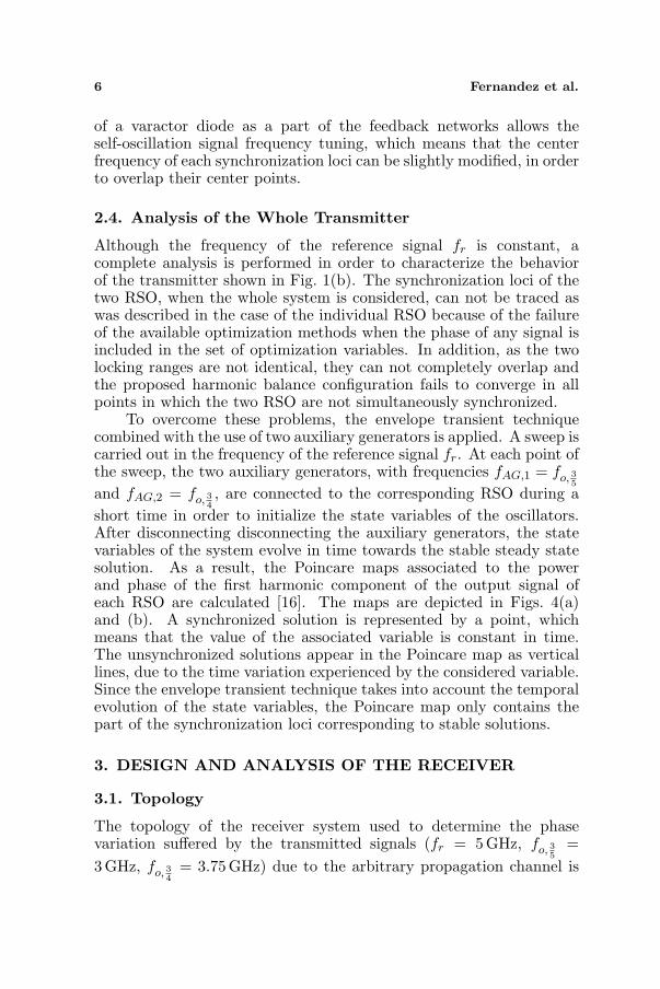
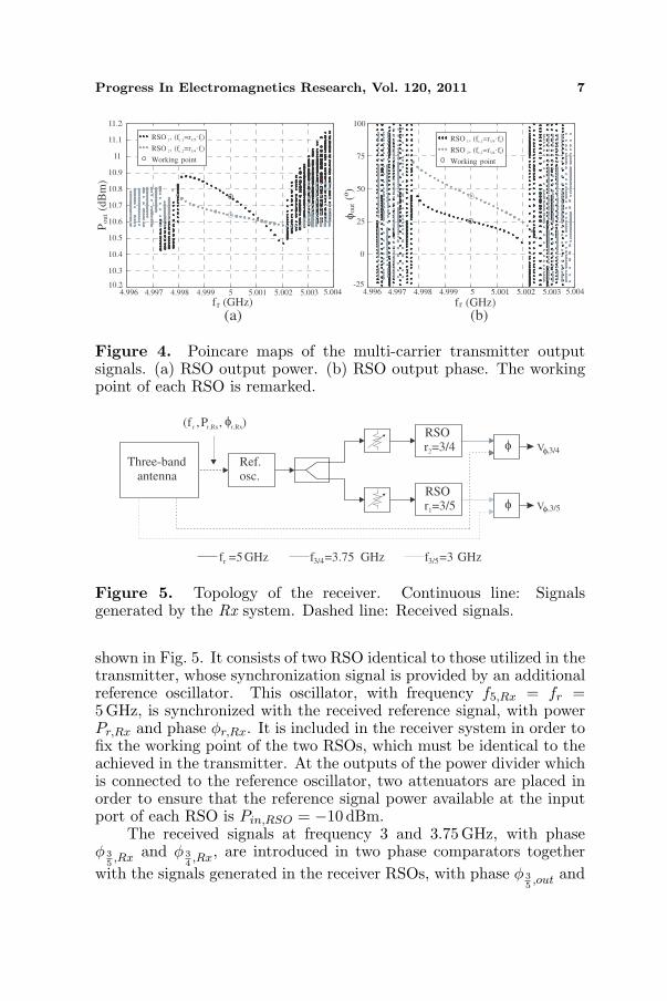
short time in order to initialize the state variables of the oscillators.After disconnecting disconnecting the auxiliary generators, the statevariables of the system evolve in time towards the stable steady statesolution. As a result, the Poincare maps associated to the powerand phase of the first harmonic component of the output signal ofeach RSO are calculated [16]. The maps are depicted in Figs. 4(a)and (b). A synchronized solution is represented by a point, whichmeans that the value of the associated variable is constant in time.The unsynchronized solutions appear in the Poincare map as verticallines, due to the time variation experienced by the considered variable.Since the envelope transient technique takes into account the temporalevolution of the state variables, the Poincare map only contains thepart of the synchronization loci corresponding to stable solutions.
3. DESIGN AND ANALYSIS OF THE RECEIVER
3.1. Topology
The topology of the receiver system used to determine the phasevariation suffered by the transmitted signals (fr = 5GHz, fo, 3
5=
3GHz, fo, 34
= 3.75GHz) due to the arbitrary propagation channel is
Progress In Electromagnetics Research, Vol. 120, 2011 7
4.996 4.997 4.998 4.999 5 5.001 5.002 5.003 5.00410.2
10.3
10.4
10.5
10.6
10.7
10.8
10.9
11
11.1
11.2
f (GHz)r
Pout(d
Bm
)
RSO , (f =r ·f )1 o,1 3/5 r
Working point
RSO , (f =r ·f )2 o,2 3/4 r
(a)
-25
0
25
50
75
100
out(º)
4.996 4.997 4.998 4.999 5 5.001 5.002 5.003 5.004
f (GHz)r
(b)
φ
RSO , (f =r ·f )1 o,1 3/5 r
Working point
RSO , (f =r ·f )2 o,2 3/4 r
Figure 4. Poincare maps of the multi-carrier transmitter outputsignals. (a) RSO output power. (b) RSO output phase. The workingpoint of each RSO is remarked.
f =5GHzr
RSO
r =3/51
RSO
r =3/42
Three-band
antenna
f =3.75 GHz3/4 f =3 GHz3/5
Ref.
osc.
V ,3/4
V ,3/5
(f ,P , )r r,Rx r,Rx
φ
φ
φ
φ
φ
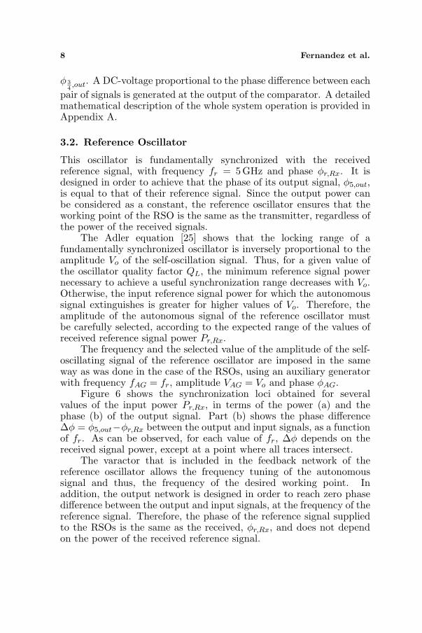
Figure 5. Topology of the receiver. Continuous line: Signalsgenerated by the Rx system. Dashed line: Received signals.
shown in Fig. 5. It consists of two RSO identical to those utilized in thetransmitter, whose synchronization signal is provided by an additionalreference oscillator. This oscillator, with frequency f5,Rx = fr =5GHz, is synchronized with the received reference signal, with powerPr,Rx and phase φr,Rx. It is included in the receiver system in order tofix the working point of the two RSOs, which must be identical to theachieved in the transmitter. At the outputs of the power divider whichis connected to the reference oscillator, two attenuators are placed inorder to ensure that the reference signal power available at the inputport of each RSO is Pin,RSO = −10 dBm.
The received signals at frequency 3 and 3.75GHz, with phaseφ 3
5,Rx and φ 3
4,Rx, are introduced in two phase comparators together
with the signals generated in the receiver RSOs, with phase φ 35,out and
8 Fernandez et al.
φ 34,out. A DC-voltage proportional to the phase difference between each
pair of signals is generated at the output of the comparator. A detailedmathematical description of the whole system operation is provided inAppendix A.
3.2. Reference Oscillator
This oscillator is fundamentally synchronized with the receivedreference signal, with frequency fr = 5 GHz and phase φr,Rx. It isdesigned in order to achieve that the phase of its output signal, φ5,out,is equal to that of their reference signal. Since the output power canbe considered as a constant, the reference oscillator ensures that theworking point of the RSO is the same as the transmitter, regardless ofthe power of the received signals.
The Adler equation [25] shows that the locking range of afundamentally synchronized oscillator is inversely proportional to theamplitude Vo of the self-oscillation signal. Thus, for a given value ofthe oscillator quality factor QL, the minimum reference signal powernecessary to achieve a useful synchronization range decreases with Vo.Otherwise, the input reference signal power for which the autonomoussignal extinguishes is greater for higher values of Vo. Therefore, theamplitude of the autonomous signal of the reference oscillator mustbe carefully selected, according to the expected range of the values ofreceived reference signal power Pr,Rx.
The frequency and the selected value of the amplitude of the self-oscillating signal of the reference oscillator are imposed in the sameway as was done in the case of the RSOs, using an auxiliary generatorwith frequency fAG = fr, amplitude VAG = Vo and phase φAG.
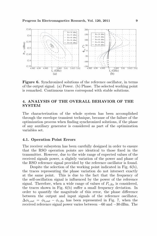
Figure 6 shows the synchronization loci obtained for severalvalues of the input power Pr,Rx, in terms of the power (a) and thephase (b) of the output signal. Part (b) shows the phase difference∆φ = φ5,out−φr,Rx between the output and input signals, as a functionof fr. As can be observed, for each value of fr, ∆φ depends on thereceived signal power, except at a point where all traces intersect.
The varactor that is included in the feedback network of thereference oscillator allows the frequency tuning of the autonomoussignal and thus, the frequency of the desired working point. Inaddition, the output network is designed in order to reach zero phasedifference between the output and input signals, at the frequency of thereference signal. Therefore, the phase of the reference signal suppliedto the RSOs is the same as the received, φr,Rx, and does not dependon the power of the received reference signal.
Progress In Electromagnetics Research, Vol. 120, 2011 9
4.985 4.99 4.995 5 5.005 5.01 5.015 5.0212.35
12.4
12.45
12.5
12.55
12.6
12.65
f (GHz)r
Pr=-30 dBm
Pr=-35 dBm
Pr=-40 dBm
Pr=-50 dBm
Pr=-60 dBm
P(d
Bm
)out
(a)
-150
-100
-50
0
50
100
150
200
4.985 4.99 4.995 5 5.005 5.01 5.015 5.02
f (GHz)r
Pr=-30 dBm
Pr=-35 dBm
Pr=-40 dBm
Pr=-50 dBm
Pr=-60 dBm
out(º)
(b)
φFigure 6. Synchronized solutions of the reference oscillator, in termsof the output signal. (a) Power. (b) Phase. The selected working pointis remarked. Continuous traces correspond with stable solutions.
4. ANALYSIS OF THE OVERALL BEHAVIOR OF THESYSTEM
The characterization of the whole system has been accomplishedthrough the envelope transient technique, because of the failure of theoptimization process when finding synchronized solutions, if the phaseof any auxiliary generator is considered as part of the optimizationvariables set.
4.1. Operation Point Errors
The receiver subsystem has been carefully designed in order to ensurethat the RSO operation points are identical to those fixed in thetransmitter. However, due to the wide range of expected values of thereceived signals power, a slightly variation of the power and phase ofthe RSO reference signal provided by the reference oscillator is found.
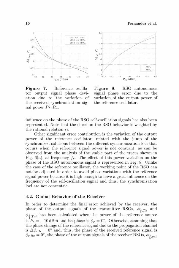
Despite the selection of the working point indicated in Fig. 6(b),the traces representing the phase variation do not intersect exactlyat the same point. This is due to the fact that the frequency ofthe self-oscillation signal is influenced by the power of the referencesignal. Therefore, when a wide range of values of Pr,Rx is considered,the traces shown in Fig. 6(b) suffer a small frequency deviation. Inorder to quantify the magnitude of this error, the phase differencebetween the output and input signals of the reference oscillator,∆φ5,out = φ5,out − φr,Rx has been represented in Fig. 7, when thereceived reference signal power varies between −60 and −30 dBm. The
10 Fernandez et al.
-60 -55 -50 -45 -40 -35 -30-0.5
-0.25
0
0.25
0.5
0.75
1
P (dBm)r,Rx
5,o
ut(º)
5,out 5,out r,RX= -
effect over RSO 3/5
effect over RSO 3/4
φ
φ φ φ∆
∆
Figure 7. Reference oscilla-tor output signal phase devi-ation due to the variation ofthe received synchronization sig-nal power Pr,Rx.
-10.3 -10.2 -10.1 -10 -9.9 -9.8 -9.7-2.5
-2
-1.5
-1
-0.5
0
0.5
1
1.5
P (dBm)out
AG
(º)
RSO 3/5
RSO 3/4
∆φ
Figure 8. RSO autonomoussignal phase error due to thevariation of the output power ofthe reference oscillator.
influence on the phase of the RSO self-oscillation signals has also beenrepresented. Note that the effect on the RSO behavior is weighted bythe rational relation ri.
Other significant error contribution is the variation of the outputpower of the reference oscillator, related with the jump of thesynchronized solutions between the different synchronization loci thatoccurs when the reference signal power is not constant, as can beobserved from the analysis of the stable part of the traces shown inFig. 6(a), at frequency fr. The effect of this power variation on thephase of the RSO autonomous signal is represented in Fig. 8. Unlikethe case of the reference oscillator, the working point of the RSO cannot be adjusted in order to avoid phase variations with the referencesignal power because it is high enough to have a great influence on thefrequency of the self-oscillation signal and thus, the synchronizationloci are not concentric.
4.2. Global Behavior of the Receiver
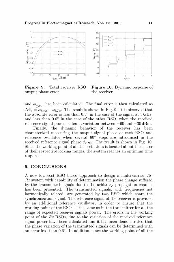
In order to determine the final error achieved by the receiver, thephase of the output signals of the transmitter RSOs, φ 3
5,Tx and
φ 34,Tx, has been calculated when the power of the reference source
is Pr = −10 dBm and its phase is φr = 0◦. Otherwise, assuming thatthe phase change of the reference signal due to the propagation channelis ∆φr,H = 0◦ and, thus, the phase of the received reference signal isφr,Rx = 0◦, the phase of the output signals of the receiver RSOs, φ 3
5,out
Progress In Electromagnetics Research, Vol. 120, 2011 11
-60 -55 -50 -45 -40 -35 -30-0.7
-0.6
-0.5
-0.4
-0.3
-0.2
-0.1
0
0.1
P (dBm)r,Rx
RSO 3/5
RSO 3/4
i,out
i,Tx
-(º)
∆φ
∆φ
Figure 9. Total receiver RSOoutput phase error.
0 1 2 3 4 5 6-60
0
60
120
180
240
300
360
t ( s)
5,out (º)
r,RX (º)
3/4,out (º)
3/5,out (º)
i,out
(º)
φ
φ
φ
φ
φ
µ
Figure 10. Dynamic response ofthe receiver.
and φ 34,out has been calculated. The final error is then calculated as
∆Φi = φi,out−φi,Tx. The result is shown in Fig. 9. It is observed thatthe absolute error is less than 0.5◦ in the case of the signal at 3GHz,and less than 0.6◦ in the case of the other RSO, when the receivedreference signal power suffers a variation between −60 and −30 dBm.
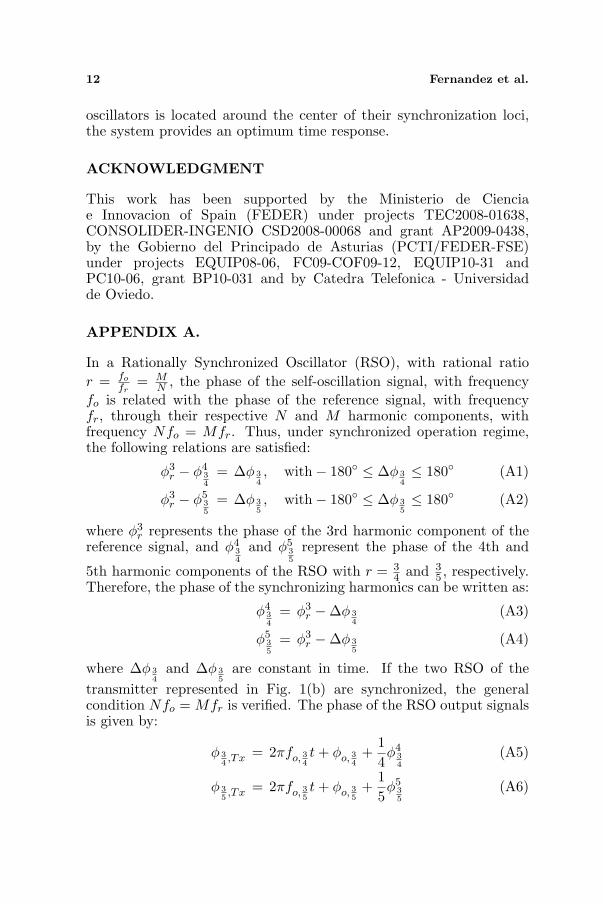
Finally, the dynamic behavior of the receiver has beencharacterized measuring the output signal phase of each RSO andreference oscillator when several 60◦ steps are introduced in thereceived reference signal phase φr,Rx. The result is shown in Fig. 10.Since the working point of all the oscillators is located about the centerof their respective locking ranges, the system reaches an optimum timeresponse.
5. CONCLUSIONS
A new low cost RSO based approach to design a multi-carrier Tx-Rx system with capability of determination the phase change sufferedby the transmitted signals due to the arbitrary propagation channelhas been presented. The transmitted signals, with frequencies notharmonically related, are generated by two RSO which share thesynchronization signal. The reference signal of the receiver is providedby an additional reference oscillator, in order to ensure that theworking point of the RSOs is the same as in the transmitter for all therange of expected receiver signals power. The errors in the workingpoint of the Rx RSOs, due to the variation of the received referencesignal power have been calculated and it has been demonstrated thatthe phase variation of the transmitted signals can be determined withan error less than 0.6◦. In addition, since the working point of all the
12 Fernandez et al.
oscillators is located around the center of their synchronization loci,the system provides an optimum time response.
ACKNOWLEDGMENT
This work has been supported by the Ministerio de Cienciae Innovacion of Spain (FEDER) under projects TEC2008-01638,CONSOLIDER-INGENIO CSD2008-00068 and grant AP2009-0438,by the Gobierno del Principado de Asturias (PCTI/FEDER-FSE)under projects EQUIP08-06, FC09-COF09-12, EQUIP10-31 andPC10-06, grant BP10-031 and by Catedra Telefonica - Universidadde Oviedo.
APPENDIX A.
In a Rationally Synchronized Oscillator (RSO), with rational ratior = fo
fr= M
N , the phase of the self-oscillation signal, with frequencyfo is related with the phase of the reference signal, with frequencyfr, through their respective N and M harmonic components, withfrequency Nfo = Mfr. Thus, under synchronized operation regime,the following relations are satisfied:
φ3r − φ4
34
= ∆φ 34, with− 180◦ ≤ ∆φ 3
4≤ 180◦ (A1)
φ3r − φ5
35
= ∆φ 35, with− 180◦ ≤ ∆φ 3
5≤ 180◦ (A2)
where φ3r represents the phase of the 3rd harmonic component of the
reference signal, and φ434
and φ535
represent the phase of the 4th and
5th harmonic components of the RSO with r = 34 and 3
5 , respectively.Therefore, the phase of the synchronizing harmonics can be written as:
φ434
= φ3r −∆φ 3
4(A3)
φ535
= φ3r −∆φ 3
5(A4)
where ∆φ 34
and ∆φ 35
are constant in time. If the two RSO of thetransmitter represented in Fig. 1(b) are synchronized, the generalcondition Nfo = Mfr is verified. The phase of the RSO output signalsis given by:
φ 34,Tx = 2πfo, 3
4t + φo, 3
4+
14φ4
34
(A5)
φ 35,Tx = 2πfo, 3
5t + φo, 3
5+
15φ5
35
(A6)
Progress In Electromagnetics Research, Vol. 120, 2011 13
where φo, 34
and φo, 35
correspond with the initial arbitrary phase valueof each RSO self-oscillation signal. Replacing (A3) in (A5), and (A4)in (A6), the phase of the transmitted signals can be expressed as:
φ 34,Tx = 2πfo, 3
4t + φo, 3
4+
14
(φ3
r −∆φ 34
)(A7)
φ 35,Tx = 2πfo, 3
5t + φo, 3
5+
15
(φ3
r −∆φ 35
)(A8)
The transmitted signals, at 3, 3.75 and 5 GHz suffer a phase changedenoted by ∆φ 3
5,H , ∆φ 3
4,H and ∆φr,H , respectively, due to the
propagation through an arbitrary channel with transfer function H(f).The phase of the received signals is then:
φr,Rx = φr,Tx + ∆φr,H (A9)φ 3
4,Rx = φ 3
4,Tx + ∆φ 3
4,H (A10)
φ 35,Rx = φ 3
5,Tx + ∆φ 3
5,H (A11)
Since the reference oscillator is fundamentally synchronized with thereceived reference signal, the phase of its output signal, which is usedas the reference of the two RSO is given by:
φ5,out = φr,Rx + φ5 = φr,Tx + ∆φr,H + φ5 (A12)
where φ5 is constant in time. By properly designing the output networkof the reference oscillator, the last expression can be re-written as:
φ5,out = φr,Rx = φr,Tx + ∆φr,H (A13)
At the Rx, the phase of received signals is:
φ 34,Rx = 2πfo, 3
4t + φo, 3
4+
14
(φ3
r −∆φ 34
)+ ∆φ 3
4,H (A14)
φ 35,Rx = 2πfo, 3
5t + φo, 3
5+
15
(φ3
r −∆φ 35
)+ ∆φ 3
5,H (A15)
and the phase of the RSO output signals can be expressed as:
φ 34,out = 2πfo, 3
4t + φo, 3
4+
14
(φ3
r + 3∆φr,H
)− 14∆φ 3
4(A16)
φ 35,out = 2πfo, 3
5t + φo, 3
5+
15
(φ3
r + 3∆φr,H
)− 15∆φ 3
5(A17)
Finally, the received signals and the generated by the receiver RSOsare introduced in two phase comparators, whose outputs are twoDC-voltage signals, Vφ, 3
4and Vφ, 3
5, which are proportional to the
phase difference between the signals connected to their two inputs.
14 Fernandez et al.
Mathematically, phase comparators perform the operations (A14)–(A16) and (A15)–(A17). Therefore, its operation is described by:
∆Φ 34
= φ 34,Rx − φ 3
4,out = ∆φ 3
4,H − 3
4∆φr,H (A18)
∆Φ 35
= φ 35,Rx − φ 3
5,out = ∆φ 3
5,H − 3
5∆φr,H (A19)
where ∆Φ 34
and ∆Φ 35
represent the phase difference betweenthe received signals and the provided by the RSOs. Therefore,Equations (A18) and (A19) show the capability of the proposedapproach to determine the relative phase change suffered by thetransmitted signals.
REFERENCES
1. Mitilineos, S. A., D. M. Kyriazanos, O. E. Segou, J. N. Goufas, andS. C. A. Thomopoulos, “Indoor localization with wireless sensornetworks,” Progress In Electromagnetics Research, Vol. 109, 441–474, 2010.
2. Seow, C. K. and S. Y. Tan, “Localization of omni-directional mo-bile device in multipath environments,” Progress In Electromag-netics Research, Vol. 85, 323–348, 2008.
3. Reza, A. W., S. M. Pillai, K. Dimyati, and K. G. Tan, “A novelpositioning system utilizing zigzag mobility pattern,” Progress InElectromagnetics Research, Vol. 106, 263–278, 2010.
4. Liu, H.-Q., H.-C. So, K. W. K. Lui, and F. K. W. Chan, “Sensorselection for target tracking in sensor networks,” Progress InElectromagnetics Research, Vol. 95, 267–282, 2009.
5. Harabi, F., H. Changuel, and A. Gharsallah, “Direction of arrivalestimation method using a 2-L shape arrays antenna,” ProgressIn Electromagnetics Research, Vol. 69, 145–160, 2007.
6. Yang, P., F. Yang, and Z. P. Nie, “DoA estimation with sub-array divided technique and interpolarted ESPRIT algorithm ona cylindrical conformal array antenna,” Progress In Electromag-netics Research, Vol. 103, 201–216, 2010.
7. Tayebi, A., J. Gomez, F. M. Saez de Adana, and O. Gutierrez,“The application of ray-tracing to mobile localization using thedirection of arrival and received signal strength in multipathindoor environments,” Progress In Electromagnetics Research,Vol. 91, 1–15, 2009.
8. Lee, J.-H., Y.-S. Jeong, S.-W. Cho, W.-Y. Yeo, and K. S. J. Pister,“Application of the Newton method to improve the accuracy of
Progress In Electromagnetics Research, Vol. 120, 2011 15
Toa estimation with the beamforming algorithm and the MUSICalgorithm,” Progress In Electromagnetics Research, Vol. 116, 475–515, 2011.
9. Alejos, A. V., M. Garcia Sanchez, I. Cuinas, and J. C. G. Val-ladares, “Sensor area network for active RTLS in RFID trackingapplications at 2.4 GHz,” Progress In Electromagnetics Research,Vol. 110, 43–58, 2010.
10. Mitilineos, S. A. and S. C. A. Thomopoulos, “Positioningaccuracy enhancement using error modeling via a polynomialapproximation approach,” Progress In Electromagnetics Research,Vol. 102, 49–64, 2010.
11. Alvarez, Y., F. Las Heras, and M. R. Pino, “Full-wave methodfor RF sources location,” Proceedings of the 2nd Eur. Conf. onAntennas and Propagation, Vol. 1, 1–5, 2007.
12. Myoung, S.-S., Y.-J. An, J.-G. Yook, B.-J. Jang, and J.-H. Moon, “A novel 10GHz super-heterodyne bio-radar systembased on a frequency multiplier and phase-locked loop,” ProgressIn Electromagnetics Research C, Vol. 19, 149–162, 2011.
13. Ver Hoeye, S., L. Gutierrez, S. Sancho, A. Suarez, andP. Gonzalez, “Sub-harmonic and rational synchronization forphase-noise improvement,” Proc. 31st Eur. Microw. Conference,Vol. 1, 237–240, 2001.
14. Ver Hoeye, S., M. G. Corredoiras, M. Fernandez, C. Vazquez,L. F. Herran, and F. Las Heras, “Harmonic optimizationof rationally synchronized oscillators,” IEEE Microwave andWireless Components Letters, Vol. 19, No. 5, 317–319, 2009.
15. Ramirez, F., E. De Cos, and A. Suarez, “Nonlinear analysis toolsfor the optimized design of harmonic-injection dividers,” IEEETransactions on Microwave Theory and Techniques, Vol. 51, No. 6,1752–1762, 2003.
16. Ver Hoeye, S., L. F. Herran, M. Fernandez, and F. Las Heras,“Design and analysis of a microwave large-range phase-shifterbased on an injection-locked harmonic self-oscillating mixer,”IEEE Microwave and Wireless Components Letters, Vol. 16, No. 6,342–344, 2006.
17. Vazquez Antuna, C., S. Ver Hoeye, M. Fernandez Garcia,L. F. Herran Ontanon, and F. Las-Heras Andres, “Analysisof the performance of injection locked oscillators in a datatransmitting polarization agile antenna application,” Progress InElectromagnetics Research Letters, Vol. 12, 1–10, 2009.
18. Ver Hoeye, S., C. Vazquez Antuna, M. Gonzalez Corredoiras,M. Fernandez Garcia, L. F. Herran Ontanon, and F. Las-Heras
16 Fernandez et al.
Andres, “Multi-harmonic DC-bias network based on arbitrarilywidth modulated microstrip line,” Progress In ElectromagneticsResearch Letters, Vol. 11, 119–128, 2009.
19. Hotopan, G. R., S. Ver Hoeye, C. Vazquez Antuna, R. CamblorDiaz, M. Fernandez Garcia, F. Las-Heras Andres, P. Alvarez,and R. Menendez, “Millimeter wave microstrip mixer based ongraphene,” Progress In Electromagnetics Research, Vol. 118, 57–69, 2011.
20. Vazquez, C., S. Ver Hoeye, C. Vazquez, M. Fernandez,L. F. Herran, and F. Las Heras, “Design of a three port tripleband aperture coupled microstrip antenna,” Proceedings of theIEEE Antennas and Propagation Symposium, Vol. 1, 95–98, 2008.
21. Chiu, C.-W., C.-H. Chang, and Y.-J. Chi, “Multiband foldedloop antenna for smart phones,” Progress In ElectromagneticsResearch, Vol. 102, 213–226, 2010.
22. Sze, J.-Y. and Y.-F. Wu, “A compact planar hexa-bandinternal antenna for mobile phone,” Progress In ElectromagneticsResearch, Vol. 107, 413–425, 2010.
23. Liao, W.-J., S.-H. Chang, and L.-K. Li, “A compact planarmultiband antenna for integrated mobile devices,” Progress InElectromagnetics Research, Vol. 109, 1–16, 2010.
24. Ver Hoeye, S., A. Suarez, and S. Sancho, “Analysis of noise effectson the nonlinear dynamics of synchronized oscillators,” IEEEMicrowave and Wireless Components Letters, Vol. 11, No. 9, 376–378, 2001.
25. Adler, R., “A study of locking phenomena in oscillators,” IEEEProceedings, Vol. 61, No. 10, 1380–1385, 1973.