Embed Size (px)
Citation preview
Design and Analysis of a Newly Installed Plate Heat Exchanger
Apparatus for the WPI Unit Operation Laboratory Course
A Major Qualifying Project submitted to the faculty of
WORCESTER POLYTECHNIC INSTITUTE
in partial fulfillment of the requirements for the
Degree of Bachelor of Science
Submitted to
Prof. William Clark: Worcester Polytechnic Institute
Submitted By
Aris Papaioannou
Kai Tang
This report represents work of WPI undergraduate students submitted to the faculty as evidence
of a degree requirement

Abstract
The goals of this project were to design a plate heat exchanger apparatus and evaluate the potential of replacing the current double pipe heat exchanger by this newly designed plate heat exchanger for the Unit Operation Laboratory Course. Raw data was collected during experiments. The goals for this project were achieved, as the team accomplished all objectives for the Heat Exchanger Unit Operation Experiment. The results obtained from the plate heat exchanger apparatus were consistent with the governing theory compared to the results from the double pipe heat exchanger apparatus.
Acknowledgements
We would like to thank our advisor, Professor W. M. Clark, for his guidance and support
throughout this project; without his overall contribution this project would not be possible.
We would also like to thank the lab manager of the WPI UO lab, Tom Partington, for his help with
ordering the necessary parts and constructing the mounting stud upon which the plate heat
exchanger was mounted.
Contents 1. Introduction ............................................................................................................................ 5
2. Background ............................................................................................................................ 8
2.1 Heat Transfer Theory........................................................................................................ 8
2.2 Heat Transfer in Heat Exchanger ........................................................................................ 9
2.3 Types of heat exchangers ...............................................................................................11
2.4 Comparison of Plate and Double Pipe heat exchangers ..................................................14
3. Methodology .........................................................................................................................16
3.1 Process development and apparatus installation .............................................................16
3.2 Test of the system ...........................................................................................................18
3.3 Improvements made to the system ..................................................................................19
3.4 Experimental process ......................................................................................................19
3.5 Data Analysis ..................................................................................................................20
4. Results and Discussion .........................................................................................................22
4.1 Heat Loss ........................................................................................................................22
4.2 Percentage of heat loss ...................................................................................................23
4.4 Effects of flow pattern ......................................................................................................24
5. Conclusions and recommendations ......................................................................................27
5.1 Conclusions .....................................................................................................................27
5.2 Recommendations ...........................................................................................................28
Reference .................................................................................................................................28
Appendix ...................................................................................................................................30
Appendix A Experimental Data ..............................................................................................31
Appendix B Analyzed data .....................................................................................................35
Appendix C Sample Calculation for heat loss (Run 1) and percentage of Qloss ....................43
Appendix D Calibration Curve for Rotameters .......................................................................44
1. Introduction A milestone in the engineering curriculum overall is the study of the transport phenomena which
consist of three interconnected branches; heat transfer, mass transfer and fluid mechanics. Heat
transfer in particular is of paramount interest to chemical engineers who deal with a plethora of
processes which involve the consumption and/or generation of energy, very often in the form of
heat. From common daily processes, such as home heating, cooking and others to virtually all
industrial processes independently of their scale, heat is transferred - exchanged - between one or
more fluids - even in humans the nasal passages operate as heat exchangers during inhaling and
exhaling. Heat exchangers are the devices used to transfer heat between one or more fluids and
serve as an important processing equipment in various industrial processes ranging from
wastewater treatment facilities to petroleum refineries and wineries.
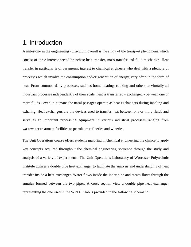
The Unit Operations course offers students majoring in chemical engineering the chance to apply
key concepts acquired throughout the chemical engineering sequence through the study and
analysis of a variety of experiments. The Unit Operations Laboratory of Worcester Polytechnic
Institute utilizes a double pipe heat exchanger to facilitate the analysis and understanding of heat
transfer inside a heat exchanger. Water flows inside the inner pipe and steam flows through the
annulus formed between the two pipes. A cross section view a double pipe heat exchanger
representing the one used in the WPI UO lab is provided in the following schematic.
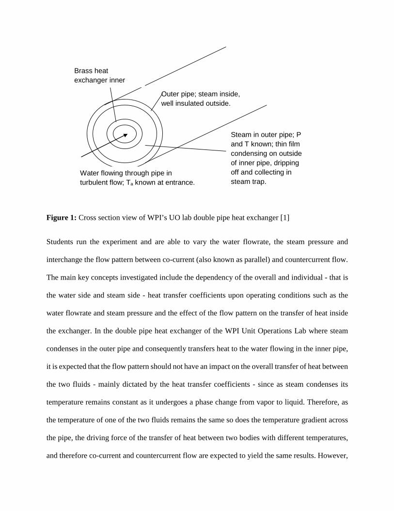
Figure 1: Cross section view of WPI’s UO lab double pipe heat exchanger [1]
Students run the experiment and are able to vary the water flowrate, the steam pressure and
interchange the flow pattern between co-current (also known as parallel) and countercurrent flow.
The main key concepts investigated include the dependency of the overall and individual - that is
the water side and steam side - heat transfer coefficients upon operating conditions such as the
water flowrate and steam pressure and the effect of the flow pattern on the transfer of heat inside
the exchanger. In the double pipe heat exchanger of the WPI Unit Operations Lab where steam
condenses in the outer pipe and consequently transfers heat to the water flowing in the inner pipe,
it is expected that the flow pattern should not have an impact on the overall transfer of heat between
the two fluids - mainly dictated by the heat transfer coefficients - since as steam condenses its
temperature remains constant as it undergoes a phase change from vapor to liquid. Therefore, as
the temperature of one of the two fluids remains the same so does the temperature gradient across
the pipe, the driving force of the transfer of heat between two bodies with different temperatures,
and therefore co-current and countercurrent flow are expected to yield the same results. However,
Brass heat exchanger inner
Steam in outer pipe; P and T known; thin film condensing on outside of inner pipe, dripping off and collecting in steam trap.
Water flowing through pipe in turbulent flow; Ta known at entrance.
Outer pipe; steam inside, well insulated outside.
students running the experiment often observed higher heat transfer coefficients when operating
on co-current flow than in countercurrent. The discrepancies arose mainly due to the configuration
of the double pipe heat exchanger and the structure of the experiment itself as often volumes of
hot water (condensed steam) were trapped at the water inlet from previous experimental runs
leading to ‘distorted’ readings and thus to an overall analysis which would not coincide with the
governing theory. Moreover, the cost of the steam supplied by the campus-wide steam plant to the
double pipe heat exchanger has also become an issue during the past few years.
The possibility of replacing the current double pipe heat exchanger used in the WPI Unit
Operations laboratory due to mainly the aforementioned reasons provides the incentive of this
study. In particular, this project focuses on the operation and analysis of a ten-plate heat exchanger
which will run on cold and hot water supplied from the building’s utility lines aiming at
determining the feasibility of using this process equipment instead of the current double pipe heat
exchanger for the Unit Operations Laboratory course at WPI.
2. Background
This section provides relevant information on heat transfer theory focusing mostly on heat transfer
inside a heat exchanger and also offers brief background information on the operation of different
types of heat exchangers putting emphasis on plate heat exchangers.
2.1 Heat Transfer Theory Heat transfer is the exchange of thermal energy between physical systems by dissipating heat. The
driving force of heat transfer is the temperature difference between the physical systems that heat
is exchanged. The theory of heat transfer from one media to another or from one fluid to another
fluid is governed by three fundamental principles. First, heat always transfers from a region of
high temperature to another region of lower temperature. Second, there must always be a
temperature difference between the media for heat to be transferred. Lastly, the heat lost by the
region of higher temperature must equal the amount of heat gained by the region of lower
temperature except for losses to the surroundings.
Heat can be transferred through four fundamental methods, also known as modes of heat transfer,
and include advection, conduction or diffusion, convection and radiation. Briefly, advection
describes the transfer of heat by the flow or movement of a fluid or a body respectively from one
location to another and is dependent upon displacement and momentum. Conduction or diffusion
refers to the transfer of heat between solids or fluids that are in physical contact and arises from
the rapid movement/vibration of atoms and molecules which transfer part of their energy (in the
form of heat) to adjacent neighboring particles. Convection is the heat transfer caused by the mass
motion of a fluid when the heated fluid is forced to move away from the source of heat carrying
energy with it in the form of heat. Finally, radiation refers to the transfer of heat due to the
movement of charged subatomic particles. Contrary to the other modes of heat transfer radiation
does not require a medium to take place; radiation can occur in absolute vacuum. In a heat
exchanger, heat is transferred through convection and conduction
2.2 Heat Transfer in Heat Exchanger In a heat exchanger, heat is first transferred from hot fluid to the surface separating the two fluids
(boundary) by convection. Next, heat is transferred through the boundary by conduction. Then
heat is transferred from the boundary to the cold fluid by convection (Cengel et al., 2008). An ideal
plate heat exchanger can be imagined as a closed system, so energy is conserved in this system,
which means the heat lost from the hot water equals to the heat gained by the cold water. In this
project, the system is not an ideal one, as there are heat losses to the surroundings, so the optimal
operating condition can be determined when the heat transfer efficiency is highest.
There are some factors that affect the heat transfer rate which can be deduced from the heat transfer
equation, the governing equation for the heat transfer rate particularly inside a heat exchanger.
𝑄𝑄 = 𝑈𝑈 ∗ 𝐴𝐴 ∗ ∆𝑇𝑇𝐿𝐿𝐿𝐿
Temperature difference between the two fluids provides the driving force for heat exchange. Thus
a greater temperature difference will result in a greater heat transfer rate. Moreover, according to
theory a higher fluid flow rate (higher fluid velocity) results in a higher heat transfer rate. The
overall heat transfer coefficient, expressed as U, also dictates the rate at which heat transfer takes
place. The overall heat transfer coefficient (U) is a measure of the overall ability of a series of
conductive and/or convective barriers to promote, or equally resist, transfer of heat. It is a function
of the individual heat transfer coefficients associated with each body or fluid participating in the
heat exchange process along with the heat transfer coefficient associated to the medium (solid as
the pipe wall or fluid as in the air) where the transfer of heat takes place and is a measure of the
medium’s ability to promote or resist heat transfer and is a function of the medium’s inherent
properties (such as its material, thickness), the conditions (temperature and pressure) and the mode
of heat transfer. Thermal conductivity of the building material affects the heat transfer rate in a
heat exchanger. Heat exchangers made of materials with higher thermal conductivity (often
denoted as k) provide higher heat transfer rate. A larger heat transfer surface area also generates a
higher transfer rate according to the heat transfer principle. The surface area available for heat
transfer is dictated by the design and manufacture of the exchanger in order to meet the heat load
requirements. In a tube and shell heat exchanger which consists of a collection of relatively thin,
long tubes which provide the surface area available for heat transfer, the more tubes contained in
the bundle the greater the surface area. The tube length also affects the heat transfer rate, as the
outside diameter and metal thickness of the tubes does.
2.3 Types of heat exchangers
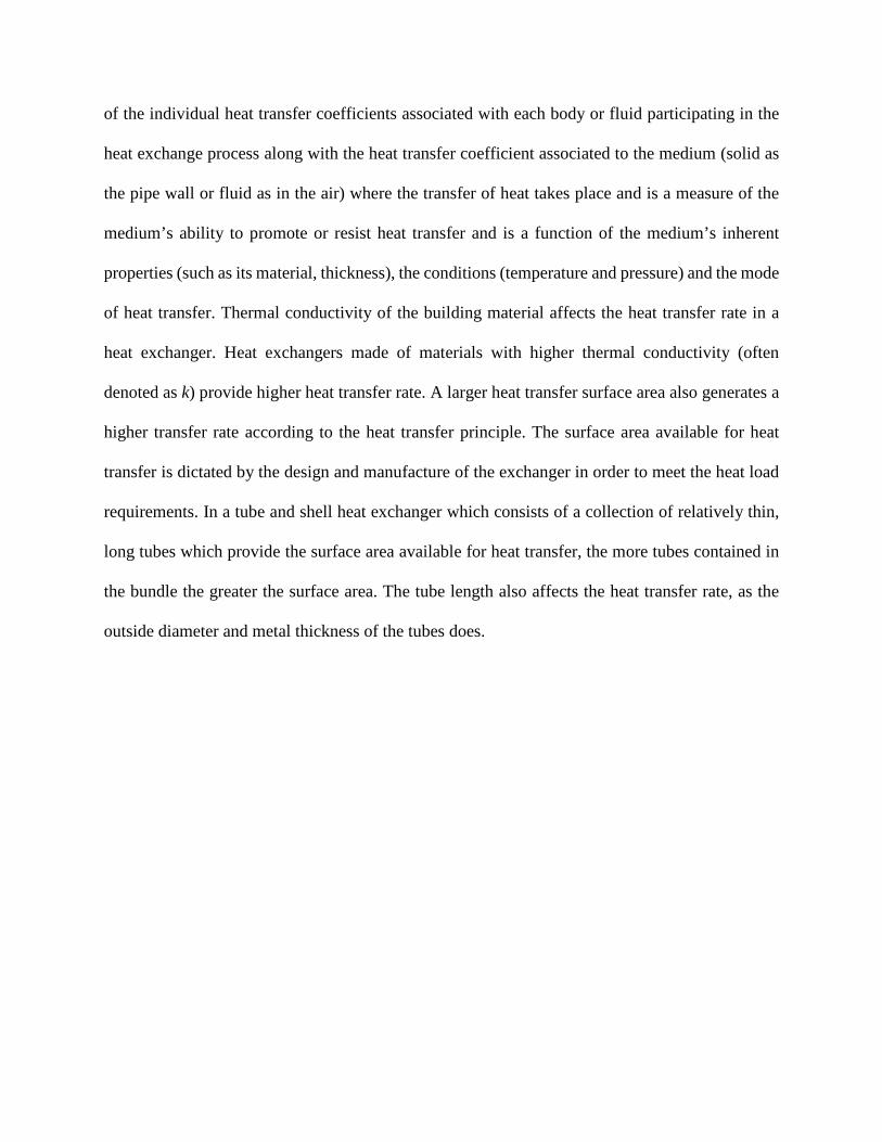
Figure 2: Double Pipe Heat Exchanger in countercurrent flow
Double pipe heat exchangers are the simplest used currently in industrial processes. They take
their name from their construction where one pipe is placed inside another pipe of bigger diameter.
Heat is exchanged between fluids running through the inside pipe and the annulus formed between
the in between pipes while the flow pattern is limited to either countercurrent or co-current flow.
Due to this configuration, double pipe heat exchangers are not very efficient in heat transfer area
while they take up considerable amount of space, the pipes need to be wider and longer in order to
obtain a larger heat transfer area. Counter-current flow will result in a better heat transfer
coefficient compared with co-current flow.
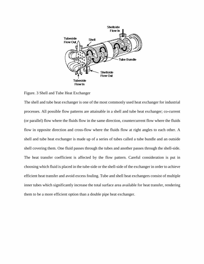
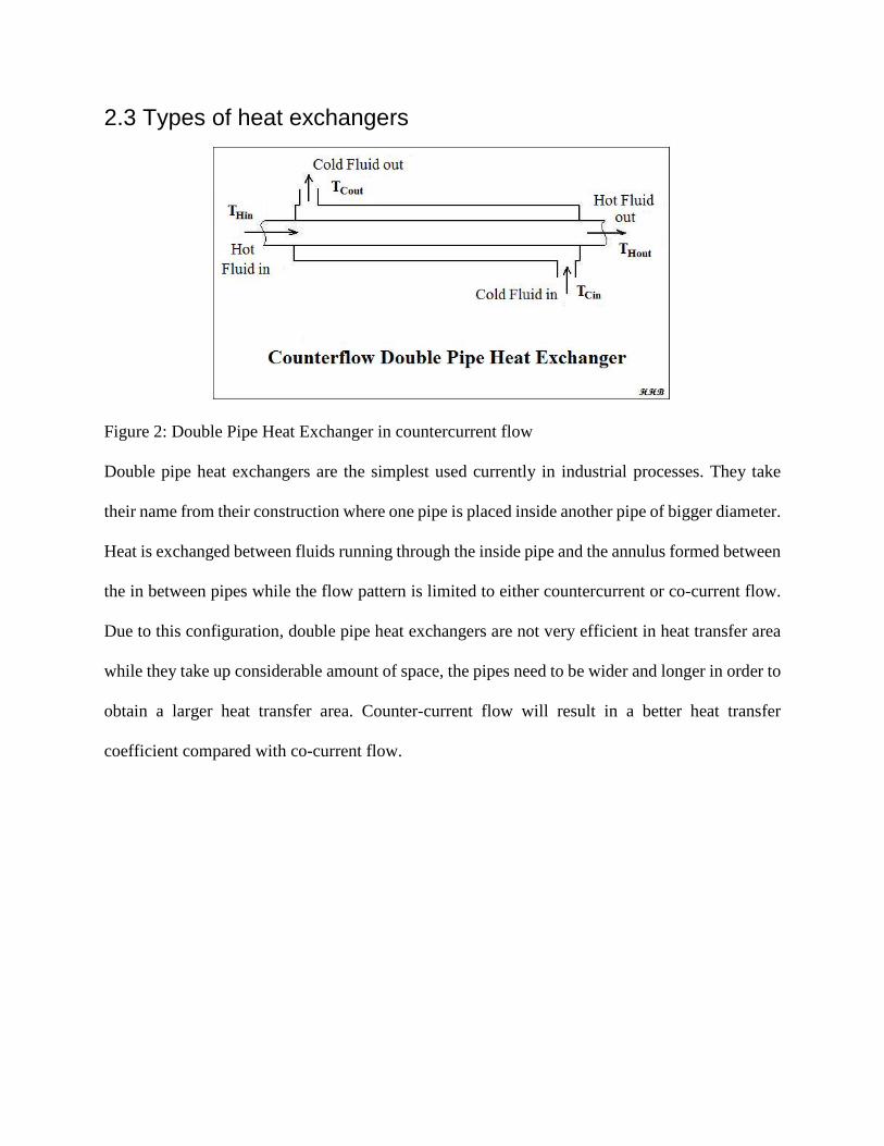
Figure. 3 Shell and Tube Heat Exchanger
The shell and tube heat exchanger is one of the most commonly used heat exchanger for industrial
processes. All possible flow patterns are attainable in a shell and tube heat exchanger; co-current
(or parallel) flow where the fluids flow in the same direction, countercurrent flow where the fluids
flow in opposite direction and cross-flow where the fluids flow at right angles to each other. A
shell and tube heat exchanger is made up of a series of tubes called a tube bundle and an outside
shell covering them. One fluid passes through the tubes and another passes through the shell-side.
The heat transfer coefficient is affected by the flow pattern. Careful consideration is put in
choosing which fluid is placed in the tube-side or the shell-side of the exchanger in order to achieve
efficient heat transfer and avoid excess fouling. Tube and shell heat exchangers consist of multiple
inner tubes which significantly increase the total surface area available for heat transfer, rendering
them to be a more efficient option than a double pipe heat exchanger.
Figure. 4 Plate Heat Exchanger
A plate heat exchanger consists of a number of heat transfer plates which are held in place between
a fixed plate and a loose pressure plate to form a complete unit. Each heat transfer plate has a
gasket arrangement which provides two separate channel systems. The arrangement of the gaskets
results in through flow in single channels, so that the primary and secondary media are in counter-
current flow. The media cannot be mixed because of the gasket design. The plates are corrugated,
which creates turbulence in the fluids as they flow through the unit. This turbulence, in association
with the ratio of the volume of the media to the size of the exchanger, gives an effective heat
transfer coefficient.
In a plate heat exchanger, heat is transferred through a metal heat exchanger plate. A plate heat
exchanger usually has higher heat transfer than a double pipe heat exchanger or shell and tube heat
exchanger. Also, plate heat exchangers are more space efficient than double pipe heat exchanger,
because of the compact size configuration and the higher heat transfer coefficient they provide.
Plate heat exchangers’ configuration can be easily modified to achieve higher heat transfer
capacity by simply adding additional plate heat exchangers.

2.4 Comparison of Plate and Double Pipe heat exchangers Plate heat exchangers have higher surface area to volume ratio than conventional double pipe heat
exchangers. The plates in a plate heat exchanger are designed to generate high turbulence, so that
plate heat exchangers usually offer a superior heat transfer coefficient. The high turbulence also
provides a self-cleaning effect. When compared to a traditional double pipe heat exchanger the
fouling of the heat transfer surfaces is considerably reduced. The advantages of a plate heat
exchanger are encompassed in its compact size, the higher heat transfer coefficient they offer, and
their easiness of cleaning and maintenance. It is estimated that in order to achieve the same amount
of work, a plate heat exchanger only requires about ⅓ to ⅕ the surface area of a conventional
double pipe heat exchanger. The double pipe heat exchanger in the UO lab occupies significantly
more space than the newly installed plate heat exchanger. In addition, due to its small size and low
operating pressure less pumping for the plate heat exchanger is required, thus the plate heat
exchanger is less expensive to purchase and to operate. Contrary to double pipe heat exchangers,
plate heat exchangers operate well even with a small temperature difference between fluids, but
do not function as well with large temperature differences. Thus, the plate heat exchanger can work
well with the utility water, and does not require steam, which can make the heat exchanger
experiment viable after the steam supply is stopped. Fouling factor, denoted as Rf, should be much
lower for a plate heat exchanger than in a double pipe one. This is due to the design of plate heat
exchangers which provides a much higher turbulence and thereby thermal efficiency than in a
typical double pipe heat exchanger. A typical k value for a plate heat exchanger operating with
water, as the one under investigation in this report, ranges between 6000-7500 W/2C while for a
double pipe one is only about 2000-2500 W/2C. From the thermal design margin equation applied
upon the design of a heat exchanger, 𝑀𝑀 = 𝑘𝑘 ∗ 𝑅𝑅𝑓𝑓 , and the aforementioned thermal conductivity

values, it is clear that fouling factor values (Rf) for a plate heat exchanger are considerably lower
than in a double pipe one. However, since the plate heat exchanger used for this project was brand
new, fouling was assumed negligible and excluded from the analysis.
3. Methodology
3.1 Process development and apparatus installation The team began designing the process of the experiment under the guide of the project advisor.
The process requires a continuous hot flow and cold flow, the utility water was chosen as the
source of cooling and heating for the exchanger. The inlet and outlet of the hot water through the
heat exchanger was connected to detachable joints, this setup allowed the team to switch between
co-current and counter-current flow patterns without the need of rebuilding the system.
In this project a 10-plate heat exchanger manufactured by Duda Energy LLC was used. The
exchanger itself had already been purchased but several extra parts needed to be ordered. These
include the tees, joints and the fittings used to establish the connections between the hoses
connecting the exchanger and the rotameters through which the water flows. Measurements of the
available hoses’ diameters were taken and the selection and ordering of the appropriate threads
and fittings was done accordingly in order to assure a safe and effective connection which would
prevent leakages and withstand fluctuations in flowrates and thus pressures. Several combinations
and trials were tested until the final leakage-free configuration was established. An appropriate
location in the WPI UO lab for the plate heat exchanger to be installed was found which provides
available space and easiness for more than one person to operate the equipment while a drain area
for the water outlets is in close vicinity. A metal plate was constructed by the lab manager meeting
the size specifications and welded onto a metallic rod and finally the plate heat exchanger was
mounted on the plate frame.
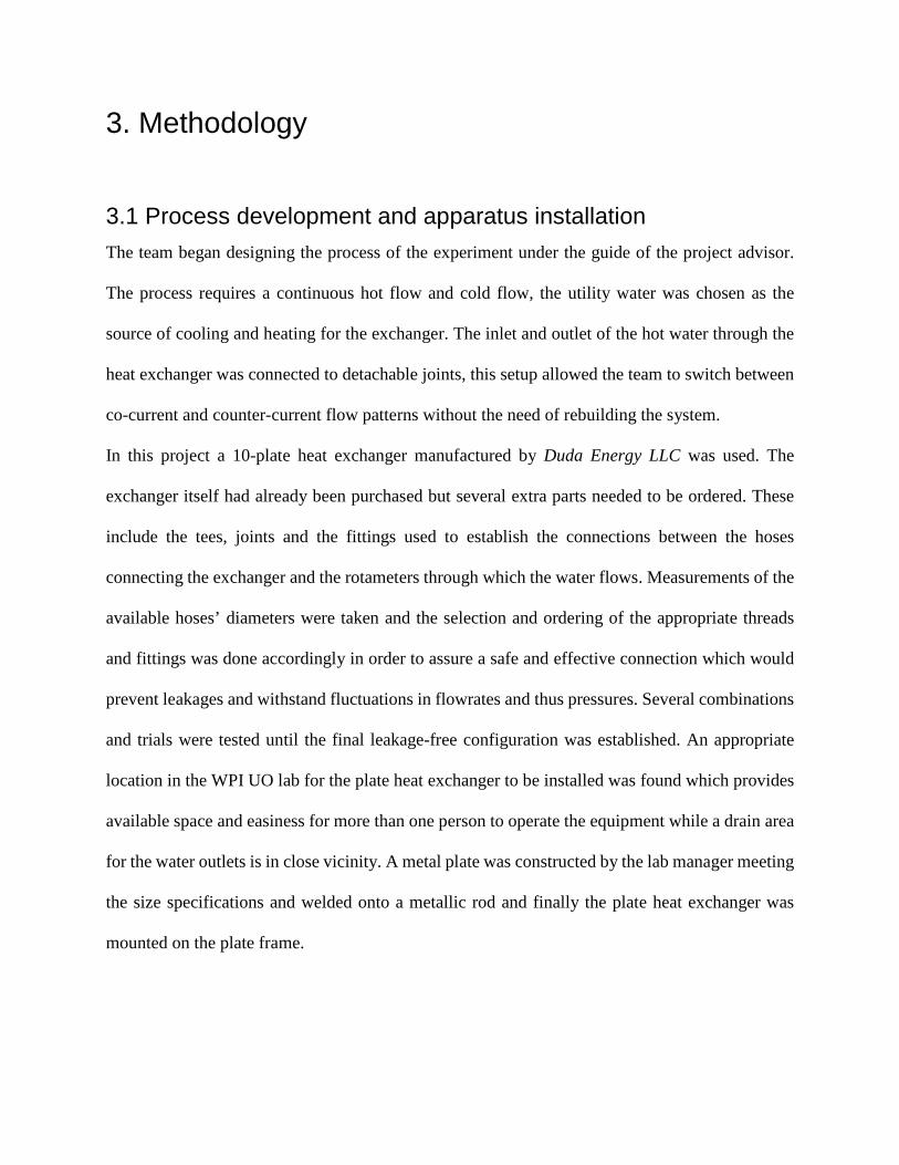
Figure. 5 Side View of the Installed Plate Heat Exchanger
According to the product specifications the total surface area available for heat transfer provided
by this specific model is 0.12 m^2 per heat transfer plate. This is a copper brazed model with
copper welding and Stainless Steel 304 plates (duda diesel). Stainless Steel is generally a good
corrosion resistive material, however for this project only hot and cold water were used, so
corrosion was not concerned. Figure 5 is a picture of the plate heat exchanger used for this project
.
Two rotameters were borrowed from the WPI Work Shop, one measuring up to 8.65GPM and was
used for the cold water, and the other measuring up to 5 GPM and was used for the hot water
flowrate. Before actually mounting the rotameters, the maximum flow capacity of each rotameter
was measured to determine their suitability for the experimental runs to follow, to prevent overflow
or insufficient flow, which both could affect the accuracy of the readings. The rotameters and the
plate heat exchanger were then bolted on a mounting stud and finally mounted to a convenient
location in the WPI Unit Operations laboratory. After hooking up the flowmeters and heat
exchangers to the water sources, calibration of the rotameters was performed to examine the
accuracy of the reading. The volume of the hot and cold water found in one minute were measured,
and compared with the reading from the flow meters. This was repeated for several flowrate
readings and a calibration curve for each rotameter was produced which can be found in the
Appendix section.
Finally, pressure gage and thermocouples were connected to the heat exchanger to measure
temperature of the inlet and outlet fluids and pressure difference between the cold and the hot side.
3.2 Test of the system The main problems usually encountered with heat exchangers are as follows:
1. Fouling: This is caused by deposits of scale, dirt, sand and/or other solid particles on the
conducting surfaces. Coke formation in furnace tubes and other causes of semi-blockage
of tubes will drastically decrease efficiency in an exchanger. Such problems will result in
shutdown for cleaning and possible tube and other parts replacements. Many of these
problems can be avoided by proper operation and fluid treatment - filtration, corrosion
inhibition, furnace firing control.
2. Air pockets: The formation of air pockets in exchanges due to improper venting at start up,
or build of gas from light materials, will affect the heat transfer rate. This can be avoided
by venting all air or gas out at start-up and periodically venting gases as required.
3. Leakage: Most leakages occur due to gasket failure - replacement of gaskets might be
necessary after some time of operation. Tube failure generally occurs due to corrosion,
excessive pressure or by failure of the welded or rolled fitting of the tubes into the tube-
sheets
The system needs to be tested before actual operation to prevent any problems mentioned above.
Additionally, to obtain a better idea of how the system operates and whether or not the system will
be suitable for this project.
3.3 Improvements made to the system During the test process of the system temperature of the inlet hot water was fluctuating
considerably, which would affect the results of this experiment, so another plate heat exchanger
was added to the system, to control the inlet hot water temperature.
3.4 Experimental process In this project comparison is the key part, thus the experiment was designed to compare the
difference between counter-current and co-current flows, as well as the effect of increasing
flowrate of one stream and keeping the other constant. The data sets were collected when flowrate
of cold was kept at 20% (of the 8.65 GPM rotameter’s rating) and the hot flowrate was increased
from 0.5 GPM to 5.0 GPM by increments of 0.5 GPM; cold kept at 40% and 60% and increasing
the hot flowrate as described above respectively. Following, the group kept the hot stream flowrate
constant and changed the flowrate of cold stream. Several data sets were collected. Finally, the
system was switched to co-current flow pattern and experiments were conducted by keeping the
cold flowrate constant at a 20% rating. The data will show the effect of varying the flowrates of
the inlet streams on the temperature levels of the outlet streams.
3.5 Data Analysis The raw data collected during the experiment was used to calculate the heat duty and the overall
heat transfer coefficient for the plate heat exchanger. The data was taken when the system reached
a steady state during each run or otherwise when the system achieved thermal equilibrium. That
was established when the temperature readings remained constant, however some minimal
fluctuation would often occur even after this point due to potential fluctuations in the flowrates as
a result of the building’s utility consumption and the precision of the temperature indicator itself
providing an uncertainty in the magnitude of the first decimal for each reading. Additionally, the
heat duty was calculated independently for hot water and cold water streams. The heat transferred
was determined using the following equation:
Q = m ∗ Cp ∗ (Tout − Tin)
where Cp is the heat capacity of water, m is the mass flow rate of the stream. Since Cp is a function
of temperature the following power equation was used for Cp of water:
𝐶𝐶𝐶𝐶 = 4.1868𝑘𝑘𝑘𝑘𝑘𝑘𝑘𝑘
∗ 𝐾𝐾(1.0038 − 2.2459 ∗ 103 (𝑇𝑇𝑇𝑇𝑇𝑇𝑇𝑇−𝑇𝑇𝑇𝑇𝑇𝑇)2
+ 2.6257 ∗ 10−6 (𝑇𝑇𝑇𝑇𝑇𝑇𝑇𝑇−𝑇𝑇𝑇𝑇𝑇𝑇)4
2).
In an ideal closed system, the heat load generated from the hot water stream must equal the heat
absorbed by the cold water stream, however this system is not an ideal one and due to heat losses
to the environment the two heat loads were not found to be equal. The heat loss is to thus
determined by 𝑄𝑄𝑄𝑄𝑄𝑄𝑄𝑄𝑄𝑄 = 𝑄𝑄ℎ − 𝑄𝑄𝑄𝑄. The overall heat transfer coefficient was calculated using
equation: 𝑈𝑈 = 𝑄𝑄/(𝐴𝐴 ∗ 𝛥𝛥𝑇𝑇𝐿𝐿𝐿𝐿), where 𝛥𝛥𝑇𝑇𝐿𝐿𝐿𝐿 is the log mean temperature difference and is calculated
by the following equation: 𝛥𝛥𝑇𝑇𝐿𝐿𝐿𝐿 = (𝑻𝑻𝑻𝑻,𝒊𝒊𝒊𝒊−𝑻𝑻𝑻𝑻,𝒐𝒐𝒐𝒐𝒐𝒐)−(𝑻𝑻𝑻𝑻,𝒐𝒐𝒐𝒐𝒐𝒐−𝑻𝑻𝑻𝑻,𝒊𝒊𝒊𝒊)
𝑳𝑳𝒊𝒊(𝑻𝑻𝑻𝑻,𝒊𝒊𝒊𝒊−𝑻𝑻𝑻𝑻,𝒐𝒐𝒐𝒐𝒐𝒐𝑻𝑻𝑻𝑻,𝒐𝒐𝒐𝒐𝒐𝒐−𝑻𝑻𝑻𝑻,𝒊𝒊𝒊𝒊)
. The estimation of the surface area
available for heat transfer is not straightforward when it comes to a plate heat exchanger. There
are contradicting methods found in literature as to what is the most accurate way of determining
the actual or effective heat transfer area of a plate heat exchanger, with some views arguing that
all number of plates should be included in the calculation, others supporting that the top and bottom
plates do not contribute in the transfer of heat and therefore should be excluded from the
calculation while others offering an area to volume ratio method for calculating the effective heat
transfer surface area. The group decided to exclude the top and bottom plates from the calculation
which were regarded as insulation barriers were no heat was transferred through these plates and
based on the model’s specifications as mentioned above where each plate provides a 0.12 m^2
surface area, the total heat transfer surface area for this plate heat exchanger was found to be (10-
2)*0.12= 0.096m2. It should also be noted here, that due to the sinusoidal corrugated pattern of
each plate surface the effective heat transfer surface area is likely to be in fact larger. However, its
exact value is hard to be determined yet it is perhaps the greatest advantage offered from such a
plate heat exchanger, which despite its compact size provides through this construction a great
available heat transfer surface area per volume and thus high overall heat transfer coefficients.
The fouling factor was disregarded because the heat exchanger was brand new and had not been
used earlier to this experiment.
4. Results and Discussion
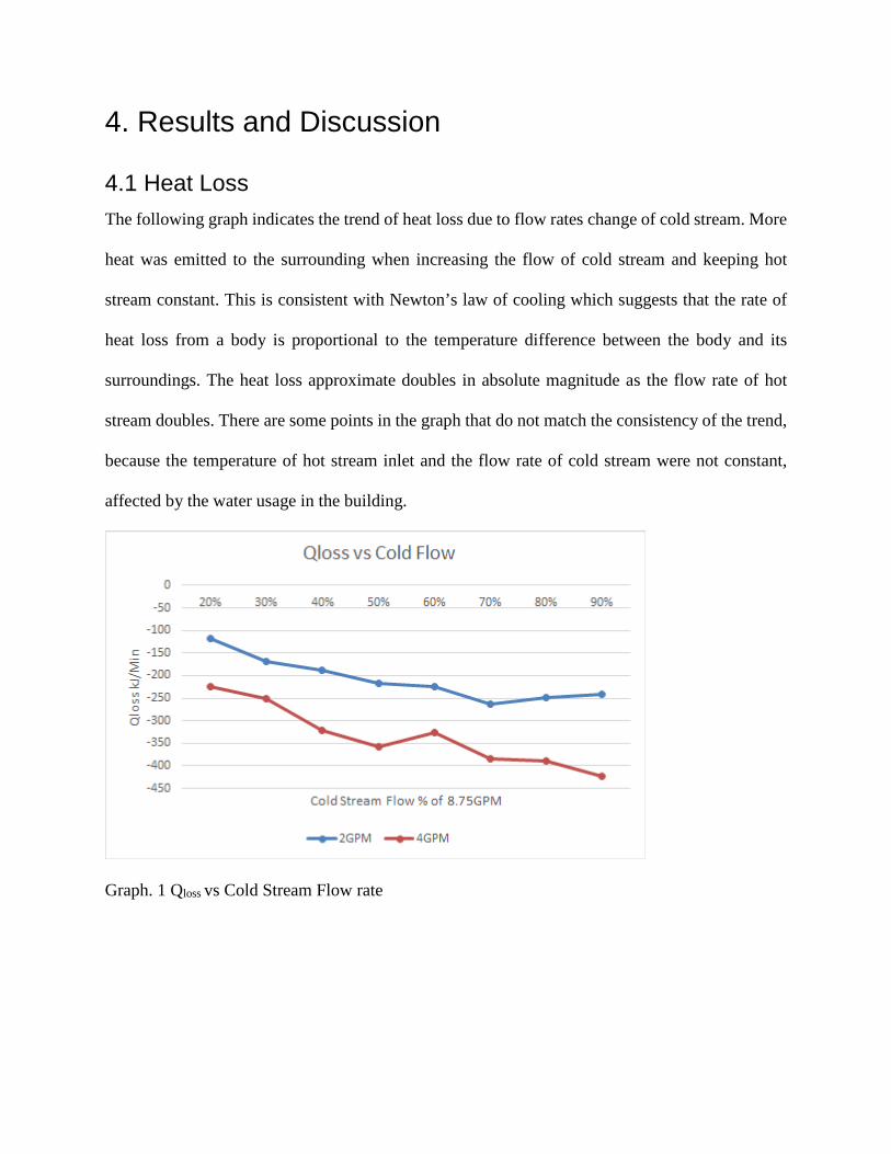
4.1 Heat Loss The following graph indicates the trend of heat loss due to flow rates change of cold stream. More
heat was emitted to the surrounding when increasing the flow of cold stream and keeping hot
stream constant. This is consistent with Newton’s law of cooling which suggests that the rate of
heat loss from a body is proportional to the temperature difference between the body and its
surroundings. The heat loss approximate doubles in absolute magnitude as the flow rate of hot
stream doubles. There are some points in the graph that do not match the consistency of the trend,
because the temperature of hot stream inlet and the flow rate of cold stream were not constant,
affected by the water usage in the building.
Graph. 1 Qloss vs Cold Stream Flow rate
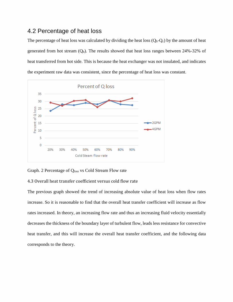
4.2 Percentage of heat loss The percentage of heat loss was calculated by dividing the heat loss (Qh-Qc) by the amount of heat
generated from hot stream (Qh). The results showed that heat loss ranges between 24%-32% of
heat transferred from hot side. This is because the heat exchanger was not insulated, and indicates
the experiment raw data was consistent, since the percentage of heat loss was constant.
Graph. 2 Percentage of Qloss vs Cold Stream Flow rate
4.3 Overall heat transfer coefficient versus cold flow rate
The previous graph showed the trend of increasing absolute value of heat loss when flow rates
increase. So it is reasonable to find that the overall heat transfer coefficient will increase as flow
rates increased. In theory, an increasing flow rate and thus an increasing fluid velocity essentially
decreases the thickness of the boundary layer of turbulent flow, leads less resistance for convective
heat transfer, and this will increase the overall heat transfer coefficient, and the following data
corresponds to the theory.
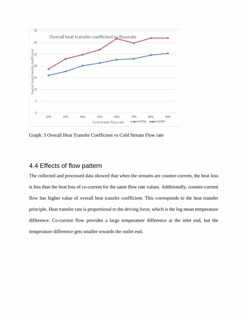
Graph. 3 Overall Heat Transfer Coefficient vs Cold Stream Flow rate
4.4 Effects of flow pattern The collected and processed data showed that when the streams are counter-current, the heat loss
is less than the heat loss of co-current for the same flow rate values. Additionally, counter-current
flow has higher value of overall heat transfer coefficient. This corresponds to the heat transfer
principle. Heat transfer rate is proportional to the driving force, which is the log mean temperature
difference. Co-current flow provides a large temperature difference at the inlet end, but the
temperature difference gets smaller towards the outlet end.
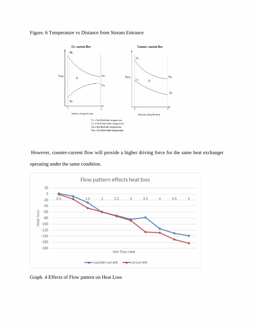
Figure. 6 Temperature vs Distance from Stream Entrance
However, counter-current flow will provide a higher driving force for the same heat exchanger
operating under the same condition.
Graph. 4 Effects of Flow pattern on Heat Loss
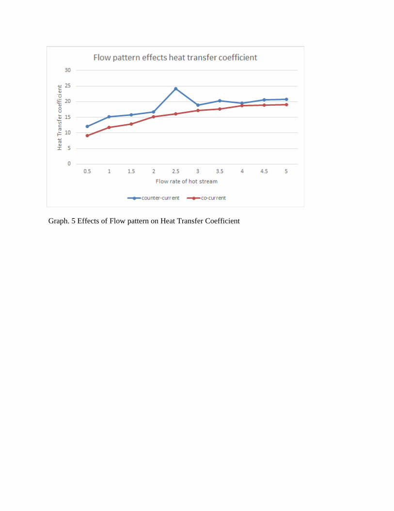
Graph. 5 Effects of Flow pattern on Heat Transfer Coefficient
5. Conclusions and recommendations
5.1 Conclusions The team determined the heat loss of the heat exchanger increased as the cooling water flow rate
was increased. However, the percentage of heat loss remained constant. According to the data,
about 24%-32% heat transferred from the hot stream was lost to the surrounding, irrespectively of
the conditions under which the system was running. The overall heat transfer coefficient also
increased as the cooling water flow rate was increased. These results were consistent with the
theory and replicate the trend the team observed from the double pipe heat exchanger in the Unit
Operation Lab. The heat transfer coefficient was calculated for both hot and cold streams, and the
heat loss to the surrounding was calculated. Unlike the double pipe heat exchanger that was
running steam, the calculation for plate heat exchanger running water in this experiment only
requires simple heat exchanging equation, and the Wilson Plot method does not apply in this case.
By comparing the results achieved by running the plate heat exchanger and double pipe heat
exchanger, it is clear that both systems can show the impact of flow rate on heat transfer
coefficient, but only plate heat exchanger will show impact of flow configuration on heat transfer
coefficient. Taking into account the exchanger’s small compact size and its significantly smaller
energy input requirement, utilizing water from the utility lines contrary to stem supplied by the
campus-wide steam plant, the new plate heat exchanger is deemed to be a proper substitution for
the current double pipe heat exchanger in the UO lab.
5.2 Recommendations The results obtained prove the necessity of further testing and experimenting on the heat exchanger
for better understanding. The overall trend of the results is consistent, however, some discrepancies
were found in the results. More experiments and improvement to the system will solve these issues
and improve the experimental analyses.
The team observed that the reading of the rotameters kept changing. Because the utility water was
used for this experiment, so the water usage in the building would significantly affect the flow rate
of the inlet water. If the inlet water was running from a continuous source, then the flow rate would
not change. By adding a reservoir, the utility water would go to the water tank first, and by
controlling the valves on the water tank, the flow rate that goes into the heat exchanger could be
maintained constant. Additionally, if the utility water gets mixed with the water stored in the
reservoir first, the temperature change of inlet stream could be minimized as well.
The goal of this project is to find out if this new plate heat exchanger system would be a good
substitution for the current double pipe heat exchanger. The results obtained from this experiment,
determined the dependency of heat loss and overall heat transfer coefficient on flowrates, the
dependency of heat loss and overall heat transfer coefficient on flow pattern. All the objectives for
the double pipe heat exchanger experiment can be achieved by running the plate heat exchanger
apparatus, and plate heat exchanger provides better results for the effects of flow directions.
Reference
Clark, W. M., “Experiment No.6: Heat Transfer from Condensing Steam to Water in a Double
Pipe Heat Exchanger”, ChE4401, Unit Operations Laboratory I, Experiment Description, (2013)
Atlas Copco 2010, Compressed Air Manual, Atlas Copco Airpower NV, Belgium.
Cengel, Y.A., Turner, R.H. & Cimbala, J.M. 2008, Fundamentals of Thermal-Fluid Sciences, 3rd
edn, McGraw-Hill, New York, NY.
"B3-12A 10 Plate Heat Exchanger with M5-.08 Mounting Studs [HX1210] | DudaDiesel Biodiesel
Supplies." B3-12A 10 Plate Heat Exchanger with M5-.08 Mounting Studs [HX1210] | DudaDiesel
Biodiesel Supplies. N.p., n.d. Web. 10 Dec. 2015. (DUDA heat exchanger
details)
Bengtson, Harlan. "Double Pipe Heat Exchanger Design with Counterflow or Parallel Flow."
Brighthub Engineering. N.p., n.d. Web. 20 Dec. 2015. (double pipe photo)
Bengtson, Harlan. "The Shell and Tube Heat Exchanger as One of Several Types of Heat
Exchangers." Brighthub Engineering. N.p., n.d. Web. 25 Jan. 2016. (tube and shell photo)
Bengtson, Harlan. "The Flat Plate Heat Exchanger in Comparison with Other Types of Heat
Exchangers." Brighthub Engineering. N.p., n.d. Web. 25 Jan. 2016. (plate heat exchanger photo)
Norrie. "HEAT TRANSFER - PRINCIPLES & EQUIPMENT - FACTORS AFFECTING HEAT
TRANSFER." HEAT TRANSFER - PRINCIPLES & EQUIPMENT - FACTORS AFFECTING
HEAT TRANSFER. N.p., n.d. Web. 25 Jan. 2016.
Fakheri, Ahmad. "Heat Exchanger Efficiency." ASME DC. American Society of MEchanical
Engineers, 16 Apr. 2006. Web. 25 Jan. 2016.
"Heat Exchanger in Bio-Chemical Process." Heat Exchanger in Bio-Chemical Process. N.p., n.d.
Web. 25 Jan. 2016.

Appendix
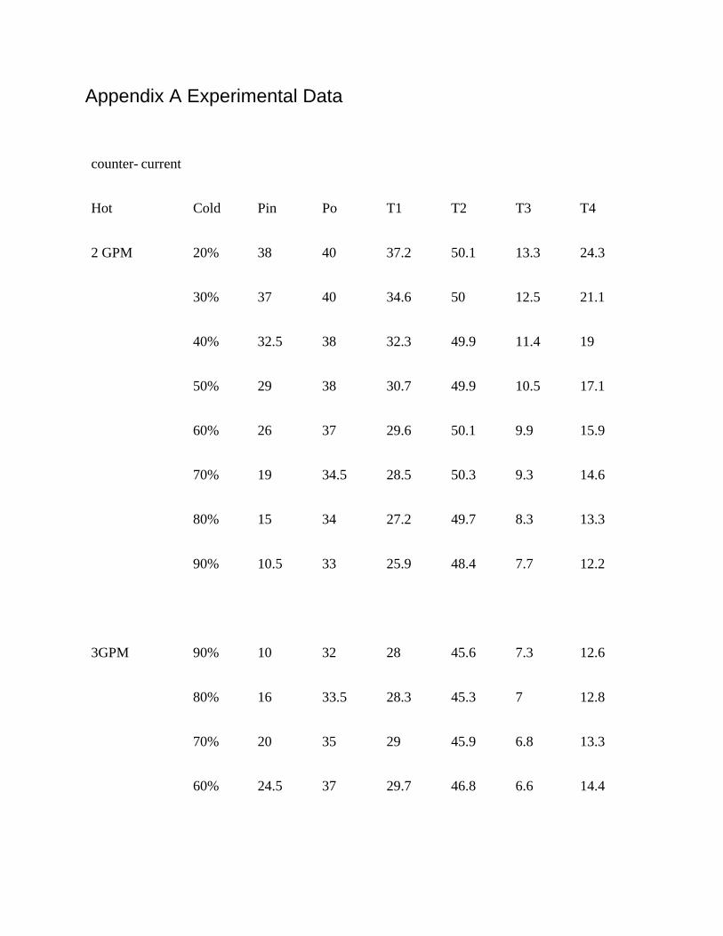
Appendix A Experimental Data
counter- current
Hot Cold Pin Po T1 T2 T3 T4
2 GPM 20% 38 40 37.2 50.1 13.3 24.3
30% 37 40 34.6 50 12.5 21.1
40% 32.5 38 32.3 49.9 11.4 19
50% 29 38 30.7 49.9 10.5 17.1
60% 26 37 29.6 50.1 9.9 15.9
70% 19 34.5 28.5 50.3 9.3 14.6
80% 15 34 27.2 49.7 8.3 13.3
90% 10.5 33 25.9 48.4 7.7 12.2
3GPM 90% 10 32 28 45.6 7.3 12.6
80% 16 33.5 28.3 45.3 7 12.8
70% 20 35 29 45.9 6.8 13.3
60% 24.5 37 29.7 46.8 6.6 14.4
50% 29 37.5 31.6 47.5 6.6 15.1
40% 32 38 33.1 48.1 6.5 16.6
30% 37 39.5 35 48.5 6.5 18.4
20% 39 40 37.7 48.9 6.6 21.2
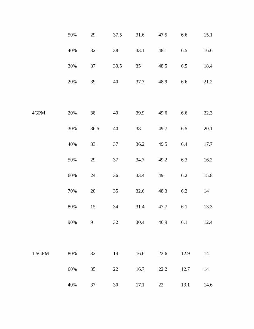
4GPM 20% 38 40 39.9 49.6 6.6 22.3
30% 36.5 40 38 49.7 6.5 20.1
40% 33 37 36.2 49.5 6.4 17.7
50% 29 37 34.7 49.2 6.3 16.2
60% 24 36 33.4 49 6.2 15.8
70% 20 35 32.6 48.3 6.2 14
80% 15 34 31.4 47.7 6.1 13.3
90% 9 32 30.4 46.9 6.1 12.4
1.5GPM 80% 32 14 16.6 22.6 12.9 14
60% 35 22 16.7 22.2 12.7 14
40% 37 30 17.1 22 13.1 14.6
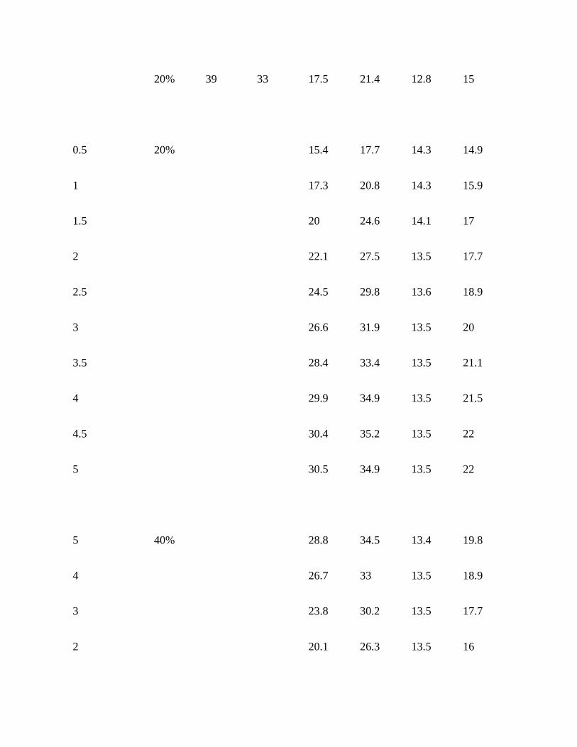
20% 39 33 17.5 21.4 12.8 15
0.5 20% 15.4 17.7 14.3 14.9
1 17.3 20.8 14.3 15.9
1.5 20 24.6 14.1 17
2 22.1 27.5 13.5 17.7
2.5 24.5 29.8 13.6 18.9
3 26.6 31.9 13.5 20
3.5 28.4 33.4 13.5 21.1
4 29.9 34.9 13.5 21.5
4.5 30.4 35.2 13.5 22
5 30.5 34.9 13.5 22
5 40% 28.8 34.5 13.4 19.8
4 26.7 33 13.5 18.9
3 23.8 30.2 13.5 17.7
2 20.1 26.3 13.5 16
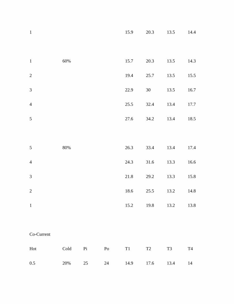
1 15.9 20.3 13.5 14.4
1 60% 15.7 20.3 13.5 14.3
2 19.4 25.7 13.5 15.5
3 22.9 30 13.5 16.7
4 25.5 32.4 13.4 17.7
5 27.6 34.2 13.4 18.5
5 80% 26.3 33.4 13.4 17.4
4 24.3 31.6 13.3 16.6
3 21.8 29.2 13.3 15.8
2 18.6 25.5 13.2 14.8
1 15.2 19.8 13.2 13.8
Co-Current
Hot Cold Pi Po T1 T2 T3 T4
0.5 20% 25 24 14.9 17.6 13.4 14
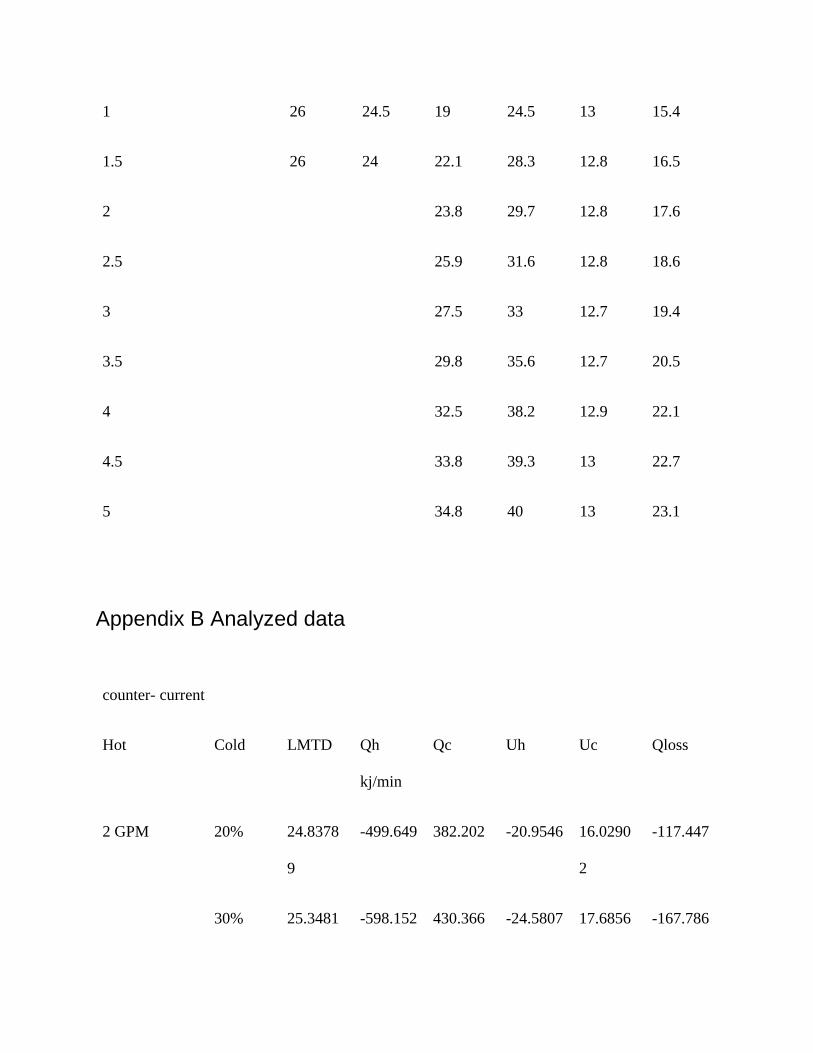
1 26 24.5 19 24.5 13 15.4
1.5 26 24 22.1 28.3 12.8 16.5
2 23.8 29.7 12.8 17.6
2.5 25.9 31.6 12.8 18.6
3 27.5 33 12.7 19.4
3.5 29.8 35.6 12.7 20.5
4 32.5 38.2 12.9 22.1
4.5 33.8 39.3 13 22.7
5 34.8 40 13 23.1
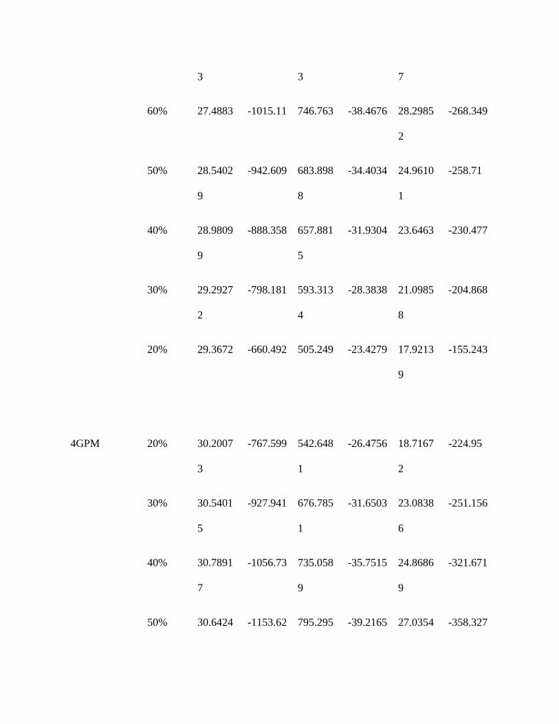
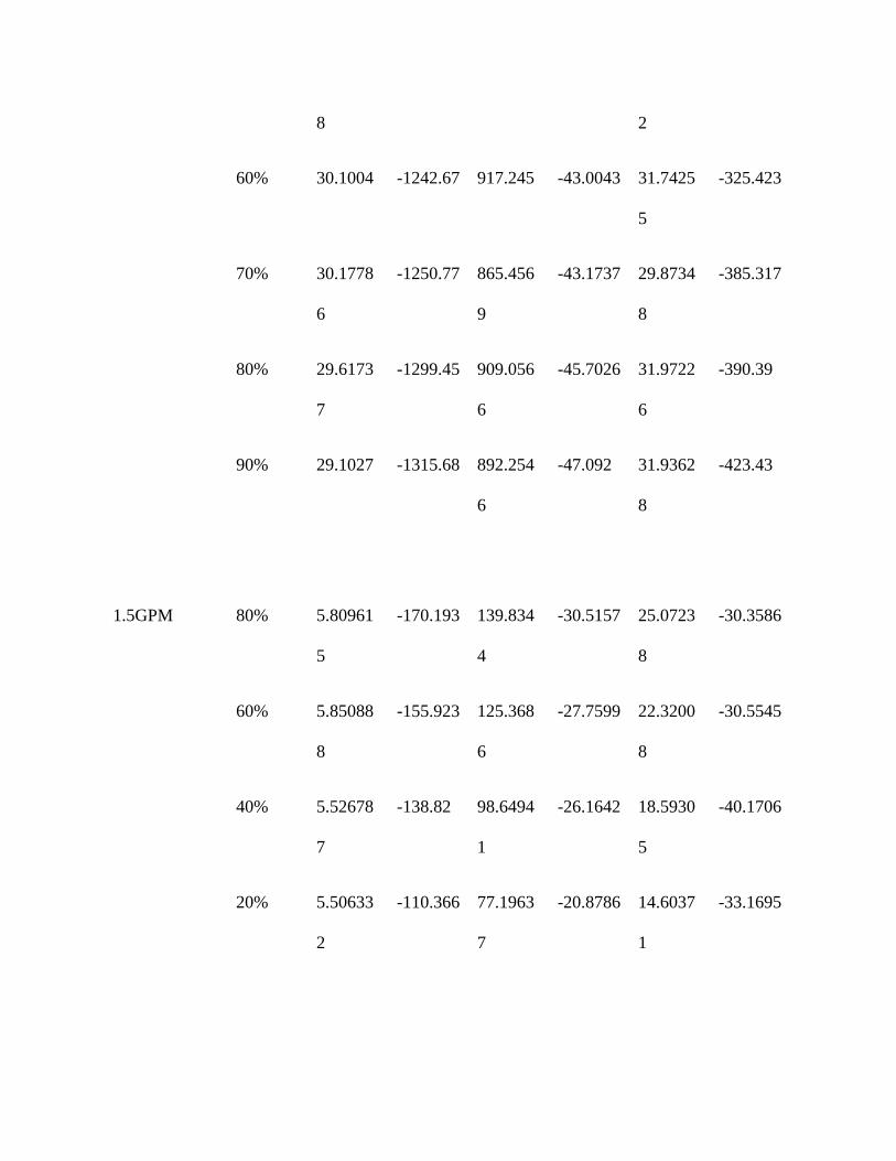
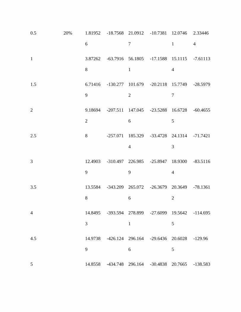
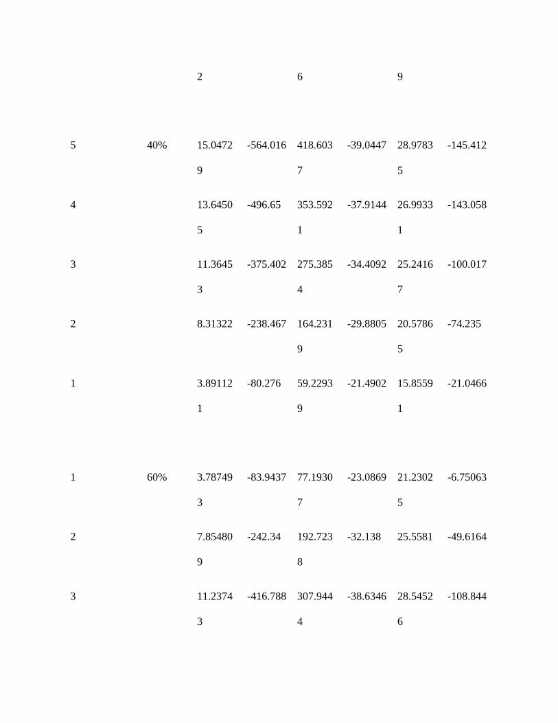
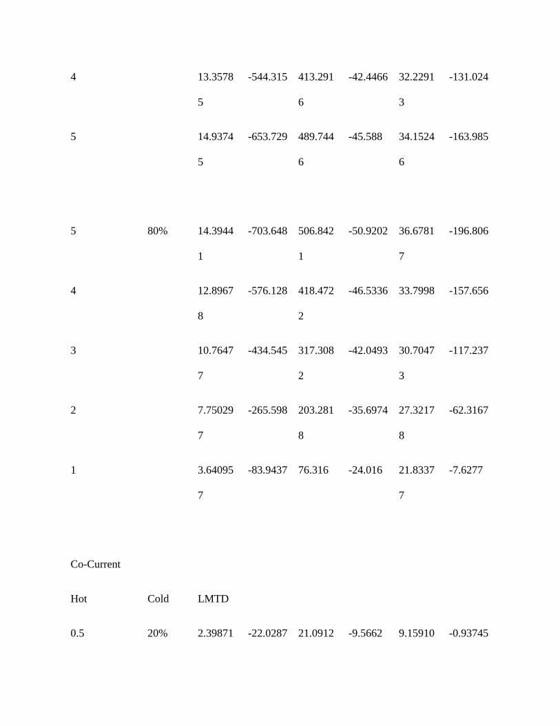
Appendix B Analyzed data
counter- current
Hot Cold LMTD Qh
kj/min
Qc Uh Uc Qloss
2 GPM 20% 24.8378
9
-499.649 382.202 -20.9546 16.0290
2
-117.447
30% 25.3481 -598.152 430.366 -24.5807 17.6856 -167.786
7 2
40% 25.5749
9
-685.288 496.425
3
-27.9117 20.2193
5
-188.863
50% 25.993 -748.927 532.156
7
-30.0132 21.3261
2
-216.771
60% 26.2868
3
-800.801 575.590
5
-31.7333 22.8088
9
-225.21
70% 26.6025
9
-852.823 589.713
3
-33.3937 23.0911
6
-263.11
80% 26.7009
7
-880.898 632.844
4
-34.3659 24.6887
2
-248.053
90% 26.1765
8
-880.898 638.609 -35.0543 25.4127 -242.289
3GPM 90% 26.3736
9
-1045.38 751.466
8
-41.2887 29.6802
6
-293.912
80% 26.5068 -1009.06 733.443 -39.6542 28.8229
1
-275.62
70% 27.0678 -1003.01 722.263 -38.5996 27.7952 -280.751
3 3 7
60% 27.4883 -1015.11 746.763 -38.4676 28.2985
2
-268.349
50% 28.5402
9
-942.609 683.898
8
-34.4034 24.9610
1
-258.71
40% 28.9809
9
-888.358 657.881
5
-31.9304 23.6463 -230.477
30% 29.2927
2
-798.181 593.313
4
-28.3838 21.0985
8
-204.868
20% 29.3672 -660.492 505.249 -23.4279 17.9213
9
-155.243
4GPM 20% 30.2007
3
-767.599 542.648
1
-26.4756 18.7167
2
-224.95
30% 30.5401
5
-927.941 676.785
1
-31.6503 23.0838
6
-251.156
40% 30.7891
7
-1056.73 735.058
9
-35.7515 24.8686
9
-321.671
50% 30.6424 -1153.62 795.295 -39.2165 27.0354 -358.327
8 2
60% 30.1004 -1242.67 917.245 -43.0043 31.7425
5
-325.423
70% 30.1778
6
-1250.77 865.456
9
-43.1737 29.8734
8
-385.317
80% 29.6173
7
-1299.45 909.056
6
-45.7026 31.9722
6
-390.39
90% 29.1027 -1315.68 892.254
6
-47.092 31.9362
8
-423.43
1.5GPM 80% 5.80961
5
-170.193 139.834
4
-30.5157 25.0723
8
-30.3586
60% 5.85088
8
-155.923 125.368
6
-27.7599 22.3200
8
-30.5545
40% 5.52678
7
-138.82 98.6494
1
-26.1642 18.5930
5
-40.1706
20% 5.50633
2
-110.366 77.1963
7
-20.8786 14.6037
1
-33.1695
0.5 20% 1.81952
6
-18.7568 21.0912
7
-10.7381 12.0746
1
2.33446
4
1 3.87262
8
-63.7916 56.1805
1
-17.1588 15.1115
4
-7.61113
1.5 6.71416
9
-130.277 101.679
2
-20.2118 15.7749
7
-28.5979
2 9.18694
2
-207.511 147.045
6
-23.5288 16.6728
5
-60.4655
2.5 8 -257.071 185.329
4
-33.4728 24.1314
3
-71.7421
3 12.4903
9
-310.497 226.985
9
-25.8947 18.9300
4
-83.5116
3.5 13.5584
8
-343.209 265.072
6
-26.3679 20.3649
2
-78.1361
4 14.8495
3
-393.594 278.899
1
-27.6099 19.5642
5
-114.695
4.5 14.9738
9
-426.124 296.164
6
-29.6436 20.6028
5
-129.96
5 14.8558 -434.748 296.164 -30.4838 20.7665 -138.583
2 6 9
5 40% 15.0472
9
-564.016 418.603
7
-39.0447 28.9783
5
-145.412
4 13.6450
5
-496.65 353.592
1
-37.9144 26.9933
1
-143.058
3 11.3645
3
-375.402 275.385
4
-34.4092 25.2416
7
-100.017
2 8.31322 -238.467 164.231
9
-29.8805 20.5786
5
-74.235
1 3.89112
1
-80.276 59.2293
9
-21.4902 15.8559
1
-21.0466
1 60% 3.78749
3
-83.9437 77.1930
7
-23.0869 21.2302
5
-6.75063
2 7.85480
9
-242.34 192.723
8
-32.138 25.5581 -49.6164
3 11.2374
3
-416.788 307.944
4
-38.6346 28.5452
6
-108.844
4 13.3578
5
-544.315 413.291
6
-42.4466 32.2291
3
-131.024
5 14.9374
5
-653.729 489.744
6
-45.588 34.1524
6
-163.985
5 80% 14.3944
1
-703.648 506.842
1
-50.9202 36.6781
7
-196.806
4 12.8967
8
-576.128 418.472
2
-46.5336 33.7998 -157.656
3 10.7647
7
-434.545 317.308
2
-42.0493 30.7047
3
-117.237
2 7.75029
7
-265.598 203.281
8
-35.6974 27.3217
8
-62.3167
1 3.64095
7
-83.9437 76.316 -24.016 21.8337
7
-7.6277
Co-Current
Hot Cold LMTD
0.5 20% 2.39871 -22.0287 21.0912 -9.5662 9.15910 -0.93745
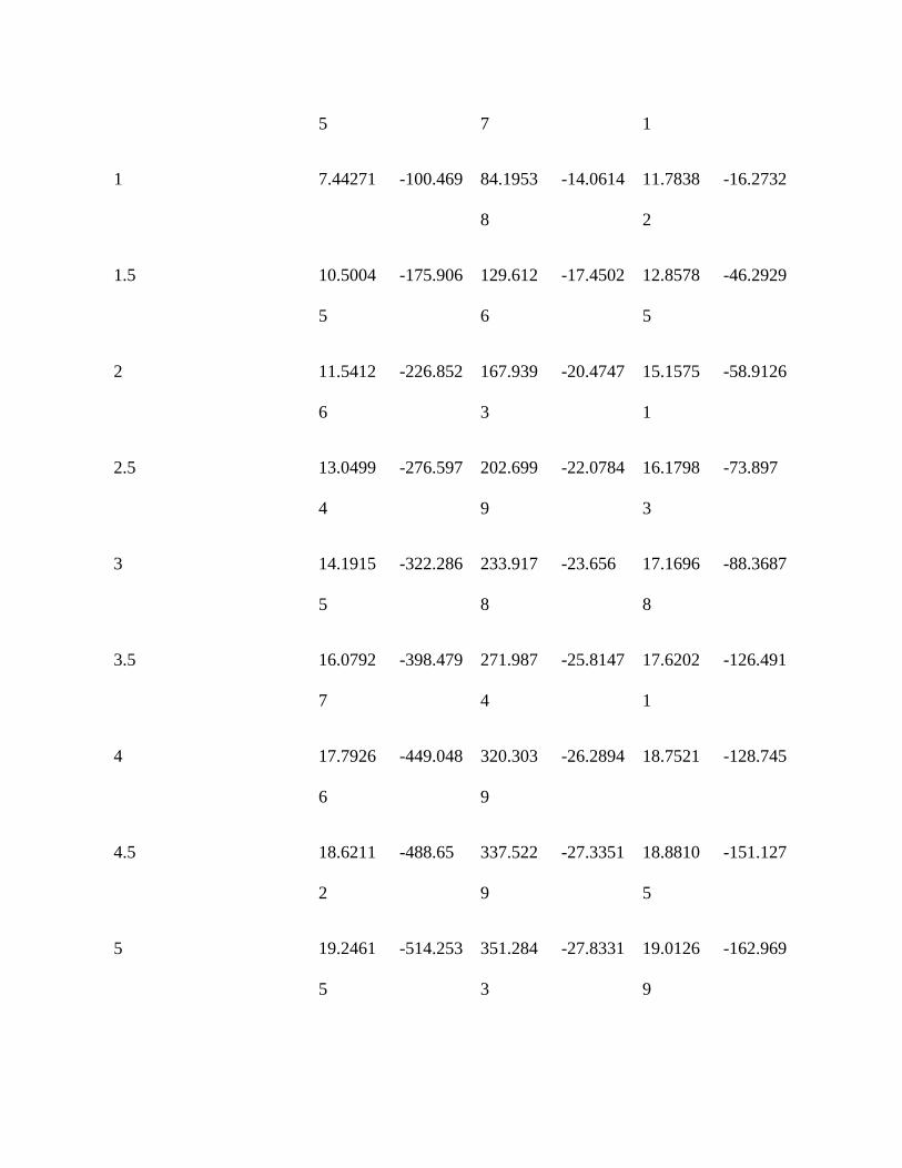
5 7 1
1 7.44271 -100.469 84.1953
8
-14.0614 11.7838
2
-16.2732
1.5 10.5004
5
-175.906 129.612
6
-17.4502 12.8578
5
-46.2929
2 11.5412
6
-226.852 167.939
3
-20.4747 15.1575
1
-58.9126
2.5 13.0499
4
-276.597 202.699
9
-22.0784 16.1798
3
-73.897
3 14.1915
5
-322.286 233.917
8
-23.656 17.1696
8
-88.3687
3.5 16.0792
7
-398.479 271.987
4
-25.8147 17.6202
1
-126.491
4 17.7926
6
-449.048 320.303
9
-26.2894 18.7521 -128.745
4.5 18.6211
2
-488.65 337.522
9
-27.3351 18.8810
5
-151.127
5 19.2461
5
-514.253 351.284
3
-27.8331 19.0126
9
-162.969
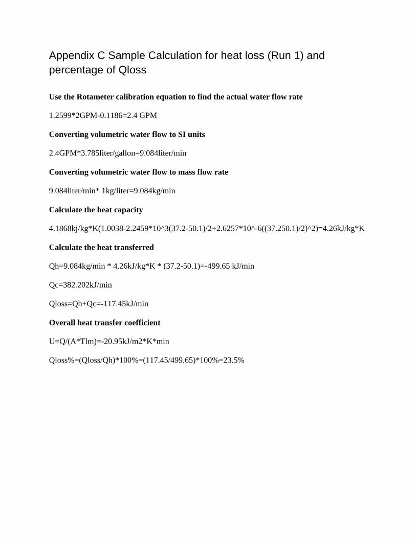
Appendix C Sample Calculation for heat loss (Run 1) and percentage of Qloss Use the Rotameter calibration equation to find the actual water flow rate
1.2599*2GPM-0.1186=2.4 GPM
Converting volumetric water flow to SI units
2.4GPM*3.785liter/gallon=9.084liter/min
Converting volumetric water flow to mass flow rate
9.084liter/min* 1kg/liter=9.084kg/min
Calculate the heat capacity
4.1868kj/kg*K(1.0038-2.2459*10^3(37.2-50.1)/2+2.6257*10^-6((37.250.1)/2)^2)=4.26kJ/kg*K
Calculate the heat transferred
Qh=9.084kg/min * 4.26kJ/kg*K * (37.2-50.1)=-499.65 kJ/min
Qc=382.202kJ/min
Qloss=Qh+Qc=-117.45kJ/min
Overall heat transfer coefficient
U=Q/(A*Tlm)=-20.95kJ/m2*K*min
Qloss%=(Qloss/Qh)*100%=(117.45/499.65)*100%=23.5%
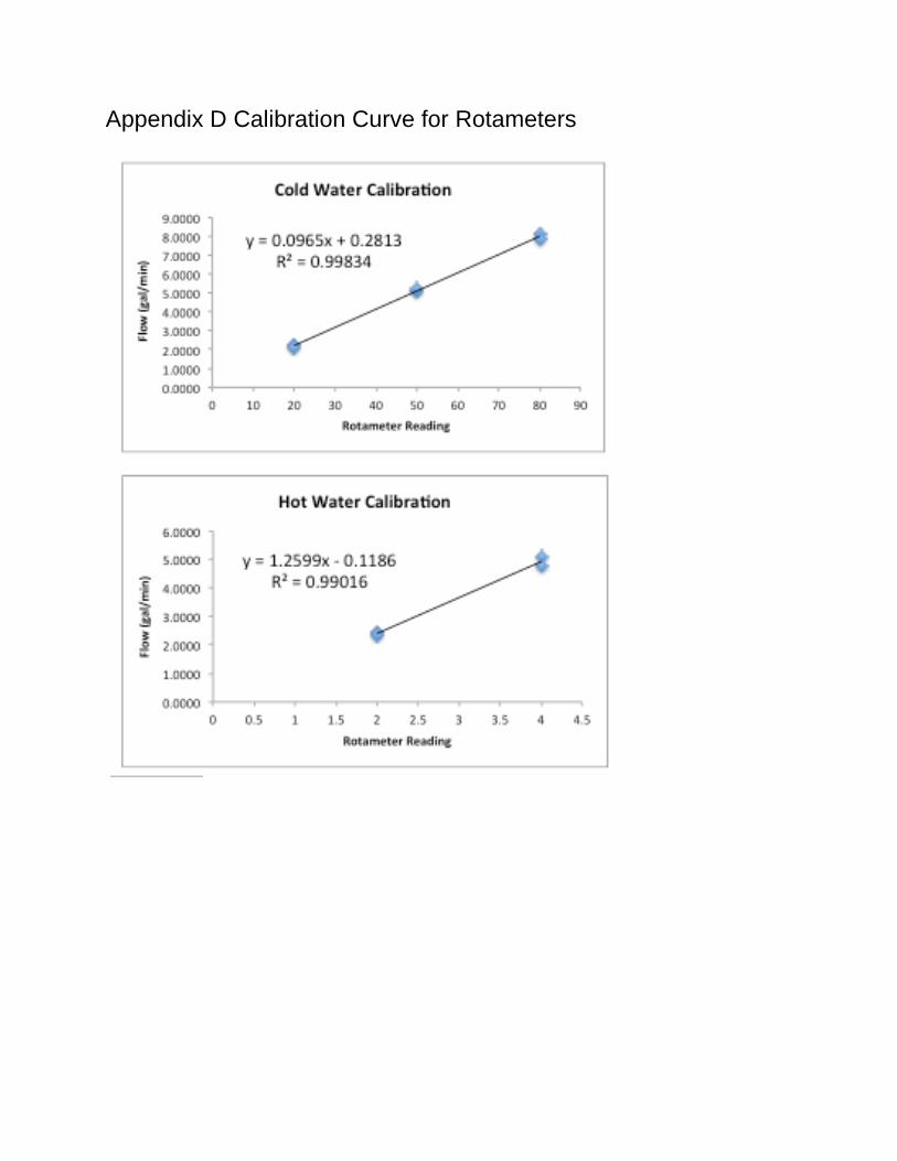
Appendix D Calibration Curve for Rotameters


![Core C-2: NMR Center P.I. C. Allen Bush [bush@umbc.edu]bush@umbc.edu Director: Bruce Johnson [johnsonb@umbc.edu]johnsonb@umbc.edu Newly Installed Instrumentation](https://img.pdfslide.net/doc/110x75/5697bfe81a28abf838cb64b9/core-c-2-nmr-center-pi-c-allen-bush-bushumbcedubushumbcedu-director.jpg)