Embed Size (px)
Citation preview
Design and Analysis of a Pedal Box System for FSAE 2010
by
Wan Nor Maawa Bin Wan Ghazali
Dissertation submitted in partial fulfilment of
the requirements for the
Bachelor of Engineering (Hons)
(Mechanical Engineering)
NOVEMBER 2009
Universiti Teknologi PETRONAS Bandar Seri Iskandar 31750 Tronoh Perak Darul Ridzuan
CERTIFICATION OF APPROVAL
Design and analysis ofa pedal box system for FSAE 2010
Approved by,
by
Wan Nor Maawa Bin Wan Ghazali
A project dissertation submitted to the
Mechanical Engineering Programme
Universiti Teknologi PETRONAS
in partial fulfilment of the requirement for the
BACHELOR OF ENGINEERING (Hons)
(MECHANICAL ENGINEERING)
~ (lr. Dr. Masri Bin Baharom)
UNIVERSITI TEKNOLOGI PETRONAS
TRONOH, PERAK
November 2009

CERTIFICATION OF ORIGINALITY
This is to certifY that I am responsible for the work submitted in this project, that the
original work is my own except as specified in the references and
acknowledgements, and that the original work contained herein have not been
undertaken or done by unspecified sources or persons.
ii
ABSTRACT
The main purpose of this project is to design and analyze an effective and practical
pedal box for the 2010 UTP Formula SAE car by improving the parameters such as
pedal box size, pedal travel, pedal ratio, input force and ergonomic concept. The
pedal box that used for braking and accelerating is a vital part of the vehicle because
the driver directly interacts with it and this makes ergonomics considerations
essential to the success of the design. The scope of study includes the material
selection, fabrication and stress-strain analysis without violating Formula SAE
design specification outlines rules. The calculations of the pedal ratio and pedal
travel angle were done using Microsoft Excel. Once the geometry was finalized, the
design was drawn using CATIA. FEA on certain key components was conducted
using the functions of the same software. The dynamics and kinematics of the design
was analyzed using ADAMS. In ADAMS, the design was simulated to obtain the
force or load distribution of the pedals. The results verified the improvement in the
final design compared to the previous design such as pedal box size reduction,
optimum pedal ratio and pedal travel values, and the ideal range of input force.
iii
ACKNOWLEDGEMENT
The author wishes to take the opportunity to express his utmost gratitude to the
individual that have taken the time and effort to assist the author in completing the
project. Without the cooperation of these individuals, the author would have faced
some minor complications throughout the project.
First and foremost the author's highest gratitude goes to the author's supervisor, Ir.
Dr. Masri Bin Baharom. Without his guidance and persistent help, the author would
not be able to complete the project. The author would like to thank to Internal
Examiners, Dr. Azman Zainuddin and Dr. Mokhtar Awang for continually giving
advices and feedbacks for the improvement of the project. To the Final Year
Research Project Coordinator, Dr. Saravanan Karuppanan and Dr. Vu Trieu Minh for
providing all the initial information and guidelines about this project.
Not to forget, to all individuals who have helped the author in any way, but whose
name are not mentioned here, the author like to thank them as well.
iv
TABLE OF CONTENTS
CERTIFICATION
ABSTRACT .
ACKNOWLEDGEMENT
TABLE OF CONTENTS
LIST OF FIGURES .
LIST OF TABLES . LIST OF EQUATIONS.
ABBREVIATION .
CHAPTER I: INTRODUCTION .
1.1 Background of Study .
1.2 Problem Statement
1.3 Objectives
1.3 Scope of Study
CHAPTER2: LITERATURE REVIEW I THEORY
2.1 Pedal Box System Fundamental
2.2 Driver Interface and Ergonomics Concept
2.3 Design Concept
2.4 Parameters Involved in Pedal Box System
Optimization
CHAPTER3: METHODOLOGY .
3.1 Procedure Identification
3.2 Tools and Equipments Required
3.3 Project Activities
CHAPTER4: RESULTS AND DISCUSSION
4.1 Foot Pedal Operation .
4.2 Material Considerations
4.3 Finite Element Analysis of Brake Pedal
4.4 Final Design
v
I
lll
IV
v
Vll
Vll1
Vll1
IX
1
I
1
3
3
4
4
6
7
13
22
14
15
16
10
10
25
26
31
CHAPTERS:
REFERENCES
APPENDICES
4.5 Brake Pedal Geometry 32
4.6 Kinematics and Dynamics Analysis of Brake
Pedal 35
4.7 Kinematics and Dynamics Analysis of
Throttle Pedal . 41
4.8 Summary oflmprovements for the New Pedal
Box Design Compared to Previous Design 44
CONCLUSION AND RECOMMENDATION 45
5.1 Conclusion 5.2 Recommendations
APPENDIX 1.
APPENDIX2.
APPENDIX3.
APPENDIX4.
APPENDIX5.
APPENDIX6.
APPENDIX7.
APPENDIX8.
VI
45 45
46
48
49
50
52
53
54
56
57
LIST OF FIGURES
Figure 2.1 Pedal Box location at front part of the car 4
Figure 2.2 Hydraulic system split configuration for front/rear hydraulic split 5
Figure 2.3 Driving position and joint angle for comfort driving position 7
Figure 2.4 Throttle pedal by Bradley John Moody 8
Figure 2.5 The position of the clutch at the shifter 9
Figure 2.6 Monash Formula SAE pedal box with LM76 Slide Rail II
Figure 2.7 Different position of master cylinders in pedal box 12
Figure 3.1 Pedal box mounting finalized design 18
Figure 3.2 Brake pedal simulation in ADAMS 19
Figure 3.3 Throttle pedal simulation in ADAMS 20
Figure 4.1 Diagram of foot depressing the pedal 22
Free body diagram of brake pedal forces 24 Figure 4.2
Figure 4.3 Constraints and force applied to the brake pedal model in finite element
analysis
Figure 4.4 Translational Displacement analysis
26
27
Figure 4.5 Pedal stress analysis on initial pedal design for maximum load (534N)
28
Figure 4.6 Pedal stress analysis on initial pedal design for maximum load (356N)
29
Figure 4.7 Redesigned brake pedal upright with reduced weight 30
Figure 4.8 Redesigned brake pedal after FEA analysis showing the reduction in
global maximum stress 30
Figure 4.9 Finalized pedal box design 31
Figure 4.10 Brake pedal geometry 32
Figure 4.11 Change in Master Cylinder vs pedal Travel for 90 to 0 degrees 35
Figure 4.12 Change in Master Cylinder vs Pedal Travel 36
Figure 4.13 Pedal Travel vs Reaction Time 37
Figure 4.14 Pedal Travel Angle vs Reaction Time 37
Figure 4.15 Pedal Ratio vs Pedal Travel 38
Figure 4.16 Force Input vs Pedal Travel 39
Figure 4.17 Graph ofinput Force vs l'l;dal Travel of pedal box design by Schiller
(2007) 40
vii
Figure 4.18 Throttle pedal geometry diagram 41
Figure 4.19 Stretched cable length vs Reaction time 42
Figure 4.20 Throttle pedal angle vs Reaction time 42
Figure 4.21 Graph of spring elongation for throttle pedal 43
Figure 4.22 Graph of spring force for throttle pedal 43
LIST OF TABLES
Table 2.1 Joint angle for comfort driving position 7
Table 2.2 Outline of the shift sequence by Enamoto et al 10
Table 3.1 Finalized design and features of brake pedal and throttle pedal 17
Table 4.1 Material Properties for materials to be used in brake pedal design 26
Table 4.2 Surmnary of Improvements for the New Pedal Box Design Compared to
Previous Design 44
LIST OF EQUATIONS
Equation 4.1 Moment calculation to find the required height of pushrod force
applied 24
Equation 4.2 Fatigue Strength
Equation 4.3
Equation 4.4
Equation 4.5
Equation 4.6
Equation 4. 7
Equation 4.8
viii
26
33
33
33
34
34
34
ABBREVIATION
SAE
FSAE
CAD
FEA
CATIA
ADAMS
EDM
Society of Automotive Engineers
Formula SAE
Computer Aided Design
Finite Element Analysis
Computer Aided Three Dimensional Interactive Application
Interactive Motion Simulation Software Modules
Electrical Discharge Machine
ix
CHAPTERl
INTRODUCTION
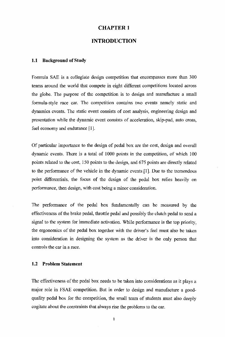
1.1 Background of Study
Formula SAE is a collegiate design competition that encompasses more than 300
teams around the world that compete in eight different competitions located across
the globe. The purpose of the competition is to design and manufacture a small
formula-style race car. The competition contains two events namely static and
dynamics events. The static event consists of cost analysis, engineering design and
presentation while the dynamic event consists of acceleration, skip-pad, auto cross,
fuel economy and endurance [1].
Of particular importance to the design of pedal box are the cost, design and overall
dynamic events. There is a total of 1000 points in the competition, of which I 00
points related to the cost, !50 points to the design, and 675 points are directly related
to the performance of the vehicle in the dynamic events [I]. Due to the tremendous
point differentials, the focus of the design of the pedal box relies heavily on
performance, then design, with cost being a minor consideration.
The performance of the pedal box fundamentally can be measured by the
effectiveness of the brake pedal, throttle pedal and possibly the clutch pedal to send a
signal to the system for immediate activation. While performance is the top priority,
the ergonomics of the pedal box together with the driver's feel must also be taken
into consideration in designing the system as the driver is the only person that
controls the car in a race.
1.2 Problem Statement
The effectiveness of the pedal box needs to be taken into considerations as it plays a
major role in FSAE competition. But in order to design and manufacture a good
quality pedal box for the competition, the small team of students must also deeply
cogitate about the constraints that always rise the problems to the car.

While designing the pedal box, the effectiveness and efficiency of the system
majorly depends on the parameters such as pedal travel, pedal ratio and force input.
It is important to know that the value of the parameters that used for race application
are different compared to the normal application. Base on the observation from
current design, pedal ratio and force input always become the problem to the car
because the driver cannot control the car efficiently if the pedal ratio is out of the
ideal range and the input force is too high.
From the previous UTP FSAE car, there were some problems regarding the mass and
cost budgets of the entire car. According to Schiller [2] the overall weight of the
vehicle must be less than 500 lbs (:::226.8 kg) to be considered remotely competitive
in the competition and after the calculations, the allocation weight for the pedal box
is only 5 lbs (""2.27 kg). According to 2009 FSAE Rules [1] the cost report
contributes 1 00 points from overall points while our previous car spends much
budget on the pedal box. Therefore, it is a must to design a light weight and cost
effective pedal box for 2010 FSAE car.
In section 7.1.4 from Formula SAE Rules [1], it is stated that "Brake-by-wire"
systems are prohibited. Therefore, the only choice that the designers have is by using
hydraulic system. We already know that hydraulic system is more effective than
using cable but the problem that arises is the required space needed for housing two
master cylinders. The pedal box may not extend beyond the bulkhead plane of the
car. It must fit between the lower frame rails that extend from the lower suspension
point to the bulkhead. With the limited space, the cylinders must be positioned
properly to avoid interfering driver's foot. The limited gap between the pedals gives
difficulties to the drivers with large foot to move from pedal to pedal.
The size and the position of the driver and the body frame also must be taken into
account while designing the pedal box. If the study of ergonomics is neglected, it
will lead several major problems to the driver and the car during racing. But in order
to design a certain system ergonomically, it is important to study first about people
that will interact with the system. The previous study shows that neglecting the
ergonomic concept affect the safety of the drivers during the race.
2
1.3 Objectives
The objectives of this project are;
a) To improve the previous design of Formula SAE car pedal box in term of
efficiency and performance involving the parameters such as pedal box size,
pedal ratio, pedal travel, force input and ergonomics concept.
b) To design a new pedal box system for Formula SAE that future generations
can use with minimal design changes.
1.4 Scope of Study
The goal of this thesis is to develop a pedal box that future generations of vehicles
can use with very minimal design changes. The thesis will outline reasons for design
decisions, part selection, material selection, as well as provide all the analysis to back
up the decisions. Technically, the Formula SAE car must be designed to comply with
the FSAE Rules. The designs that not follow the rules will be disqualified during the
inspection. Therefore all the specifications and details will be based on the
regulations. As for the pedal box, the design will be referred to the previous design
but with some adjustments to improve its performance and efficiency.
The project involves the ergonomics study, material selection, stress-strain analysis,
kinematic and dynamic analysis and fabrication process. The study will be based on
research and experiments with the aid of several software, namely Microsoft Excel,
CATIA, and ADAMS. Microsoft Excel was used to program the formula for the
calculation involving pedal box fundamental geometries. CATIA was used for
designing and modeling of the CAD and ADAMS is used to simulate the system. For
keeping the track of time, the Gantt chart was developed for the both semesters; the
first semester was focused on the literature review while the second semester was for
project activities and results.
The elements that beyond the scopes are controller, clutch, spring and retainer
mechanism and hydraulic cable linkage system.
3
CHAPTER2
LITERATURE REVIEW I THEORY
2.1 Pedal Box System Fundamental
The pedal box for Formula SAE car consists of the throttle pedal and brake pedal.
The system receives the driver's command by foot to control the vehicle motion. The
pedal box may also contain clutch pedaL If the pedal box does not contain clutch,
then the clutch must be placed on the shifter.
2.1.1 Frame
To accommodate drivers of all sizes, the pedal box must be adjustable and for the
driver's comfort, the foot rest will be installed. The pedal box must fit the two lower
of frame rails the run from the lower front suspension to the bulkhead. This means
the pedals initial position cannot be beyond the bulkhead but when the pedals are
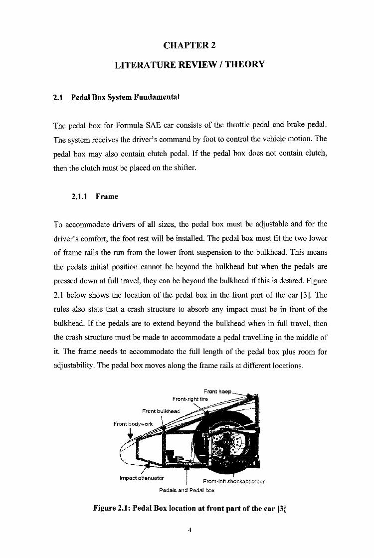
pressed down at full travel, they can be beyond the bulkhead if this is desired. Figure
2.1 below shows the location of the pedal box in the front part of the car [3]. The
rules also state that a crash structure to absorb any impact must be in front of the
bulkhead. If the pedals are to extend beyond the bulkhead when in full travel, then
the crash structure must be made to accommodate a pedal travelling in the middle of
it. The frame needs to accommodate the full length of the pedal box plus room for
adjustability. The pedal box moves along the frame rails at different locations.
Impact attem1ator
Front hoop Front-right tire
Pedals an:l Pedal box
Figure 2.1: Pedal Box location at front part of the car [3]
4
2.1.2 Brake System
According to the rules, "drive-by-wire" is prohibited and the brake system must have
two independent hydraulic circuits [1]. Therefore the pedal box must house two
master cylinders, one for the front brake system and one for the rear brake system.
The master cylinder has to be chosen properly because the size of the master
cylinder's piston has a direct result on brake fluid pressure [4]. The pedal box also
must have balance bar (bias bar) to transfer the output force from the pedal to the
master cylinders. The main function of the balance bar is to divide the leg input force
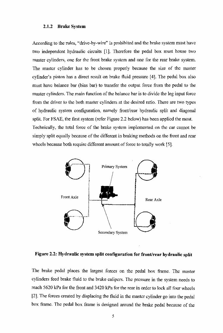
from the driver to the both master cylinders at the desired ratio. There are two types
of hydraulic system configuration, namely front/rear hydraulic split and diagonal
split. For FSAE, the first system (refer Figure 2.2 below) has been applied the most.
Technically, the total force of the brake system implemented on the car cannot be
simply split equally because of the different in braking methods on the front and rear
wheels because both require different amount of force to totally work [5].
Primary System
Front Axle Rear Axle
Secondary System
Figure 2.2: Hydraulic system split configuration for front/rear hydraulic split
The brake pedal places the largest forces on the pedal box frame. The master
cylinders feed brake fluid to the brake calipers. The pressure in the system needs to
reach 5620 kPa for the front and 3420 kPa for the rear in order to lock all four wheels
[2]. The forces created by displacing the fluid in the master cylinder go into the pedal
box frame. The pedal box frame is designed around the brake pedal because of the
5
large force. The force applied by the human to lock the wheels should be about 445
N from driver experience [2].
2.1.3 Intake System
The accelerator interacts with the throttle body on the intake system. A throttle is the
mechanism by which the flow of a fluid is managed by constriction or obstruction.
An engine's power can be increased or decreased by the restriction of inlet gases but
usually decreased. The term throttle has come to refer, informally and incorrectly, to
any mechanism by which the power or speed of an engine is regulated. What is often
termed a throttle is more correctly called a thrust lever [ 6].
In a petrol internal combustion engine, the throttle is a valve that directly regulates
the amount of air entering the engine, indirectly controlling the fuel burned on each
cycle due to the fuel-injector or carburetor maintaining a relatively constant fuel/air
ratio. In a motor vehicle the control used by the driver to regulate power is
sometimes called the throttle pedal or accelerator [ 6].
The throttle which is a basic pull cable attaches the throttle body to the accelerator.
The cable must connect to the accelerator without interfering with the driver's foot.
The pedal must return to its original position when a force is not applied and the
cable must go back to its initial position as welL When the driver presses on the
accelerator pedal, the throttle plate rotates within the throttle body, opening the
throttle passage to allow more air into the intake manifold. The interactions with the
clutch on the engine's transmission acts the same way with that the throttle cable
works [6].
2.2 Driver Interface and Ergonomics Concept
Maximizing driver's performance under racing circumstances is one of the top aims
of the vehicle design. From the outset, as required by Formula SAE rules, driver
ergonomics were considered by including a 95th percentile male driver in the space
frame model [I]. The measures taken to optimize driver interaction ensured that
cockpit layout was appropriate and that the controls were strategically positioned for
6
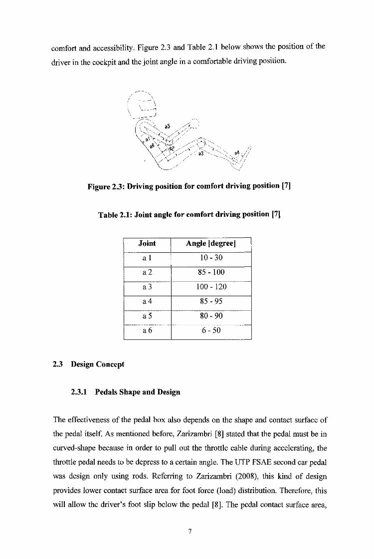
comfort and accessibility. Figure 2.3 and Table 2.1 below shows the position of the
driver in the cockpit and the joint angle in a comfortable driving position.
\ _._ ___ .--11
_I -- -"~
a4 - --t--·- ., ....
·- '"-,_ / _;
Figure 2.3: Driving position for comfort driving position [7]
Table 2.1: Joint angle for comfort driving position [7]
Joint Angle [degree]
a 1 10-30
a2 85- 100
a3 100- 120
a4 85-95
a5 80-90
a6 6-50
2.3 Design Concept
2.3.1 Pedals Shape and Design
The effectiveness of the pedal box also depends on the shape and contact surface of
the pedal itself. As mentioned before, Zarizambri [8] stated that the pedal must be in
curved-shape because in order to pull out the throttle cable during accelerating, the
throttle pedal needs to be depress to a certain angle. The UTP FSAE second car pedal
was design only using rods. Referring to Zarizambri (2008), this kind of design
provides lower contact surface area for foot force (load) distribution. Therefore, this
will allow the driver's foot slip below the pedal [8]. The pedal contact surface area,
7
to which the force is applied by the foot, is considered optimal for occasional use
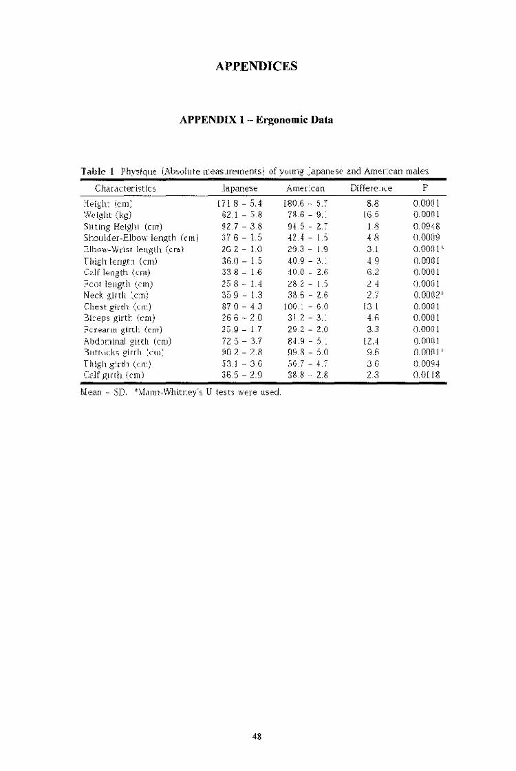
when it has a length and width of 80 x 90mrn (Eastman Kodak, 1983) [9]. Ergonomic
Data (Appendix 1) [10] states that maximum Japanese man's foot length which is
similar to Asian man is 272 mm, will be set as the maximum height of the pedal pad.
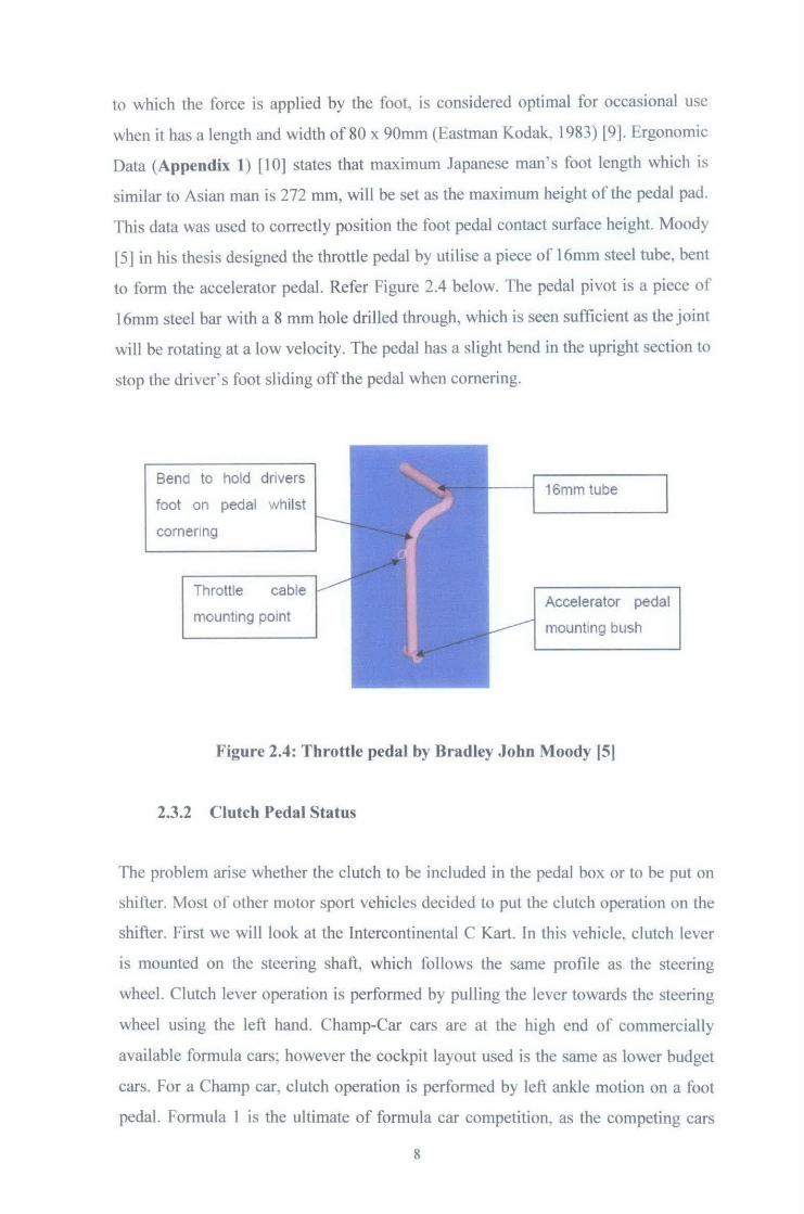
This data was used to correctly position the foot pedal contact surface height. Moody
[5] in his thesis designed the throttle pedal by utilise a piece of 16mm steel tube, bent
to form the accelerator pedal. Refer Figure 2.4 below. The pedal pivot is a piece of
16mm steel bar with a 8 mm hole drilled through, which is seen sufficient as the joint
will be rotating at a low velocity. The pedal has a slight bend in the upright section to
stop the driver's foot sliding off the pedal when cornering.
Bend to hold drivers
foot on pedal whilst
cornering
Throttle cable
mounting po1nt
16mm tube
Accelerator pedal
mounting bush
Figure 2.4: Throttle pedal by Bradley John Moody [5]
2.3.2 Clutch Pedal Status
The problem arise whether the clutch to be included in the pedal box or to be put on
shifter. Most of other motor sport vehicles decided to put the clutch operation on the
shifter. First we will look at the Intercontinental C Kart. In this vehicle, clutch lever
is mounted on the steering shaft, which follows the same profile as the steering
wheel. Clutch lever operation is performed by pulling the lever towards the steering
wheel using the left hand. Champ-Car cars are at the high end of commercially
available formula cars: however the cockpit layout used is the same as lower budget
cars. For a Champ car, clutch operation is performed by left ankle motion on a foot
pedal. Formula 1 is the ultimate of formula car competition. as the competing cars
8
cannot be purchased, and are bui lt by each team and respective technical partners to
maximise the potential of their large annual budgets. For this reason no two team's
car are exactly the same but driver cockpit layouts have been optimised over decades
of racing to produce a similar solution throughout the competition. Clutch operation
over recent years has moved from a foot control, to a hand control with the
development of electronic control 'by-wire· systems. Currently the clutch is mounted
on the back of the steering wheel and is also an electronic control.
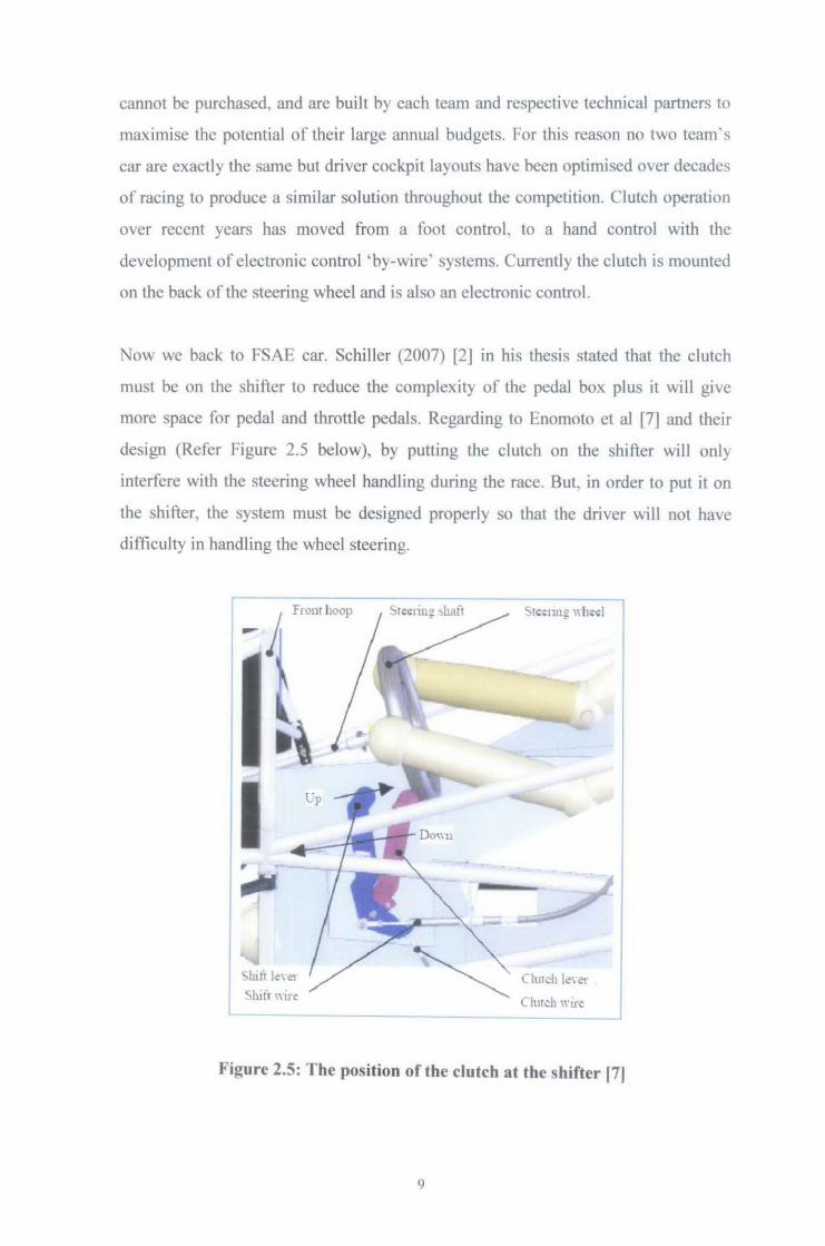
Now we back to FSAE car. Schiller (2007) [2] in his thesis stated that the clutch
must be on the shifter to reduce the complexity of the pedal box plus it will give
more space for pedal and throttle pedals. Regarding to Enomoto et al [7] and their
design (Refer Figure 2.5 below), by putting the clutch on the shifter will only
interfere with the steering wheel handling during the race. But in order to put it on
the shifter, the system must be designed properly so that the driver will not have
difficulty in handling the wheel steering.
from hoop
Shift le\·~
!:.h1tf "ire Clutch le\ e~
Clmch w1te
Figure 2.5: The position of the clutch at the shifter 171
9
For the clutch at the shifter, a light-weight, small size and high-quality transmission
should be mounted on the FSAE car and many teams use the super-sports bike built
in transmissions. For this type of transmission, the drivers should control these
transmissions manually shown in Table 2.2(a). For such amateur drivers or the
weekend racers defmed in FSAE rules, the quick and accurate operations are not
easy because large acceleration occurs in accelerating, decelerating and cornering.
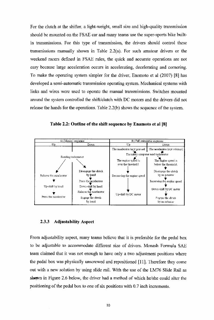
To make the operating system simpler for the driver, Enomoto et a! (2007) [8] has
developed a semi-automatic transmission operating system. Mechanical systems with
links and wires were used to operate the manual transmissions. Switches mounted
around the system controlled the shift/clutch with DC motors and the drivers did not
release the hands for the operations. Table 2.2(b) shows the sequence of the system.
Table 2.2: Outline of the shift sequence by Enamoto et al [8]
(a) Manual seQuence (b) Fnll-autQnmtiJ;: ~e u:ence Up I Do\\11 co I DOV.1l
I Tite accelerator kept pres':.ed I I11e accelerat(ll· kept rd.;n~.edl '& If.
T11e micro comJmtet' r.:nd rnctH:~meter R~.llding f8cllorneter
Th~ engine sp/£ l:;, Th~g:ine speed i:;,
I ~ on1· the th.re~hold. below the thre~hol.d,
~ t Di~eng.a~ the dutch Di.~eng.ng:e the ch1t;;h
Relea~e the accek-raror by !land Decre<l'>ing: the engine ~pee:d hv :m actLmtor
+ ,
l . +
Prr:ss the..;ccelerntor ruc1·ertsing th+-ewPne speed
Up-~hift by hm1.d
R::::·;~F::::::~ ... Down-shift by DC m.olor
Cp->hift by DC motor· .. Pre.:;s the :1ccelemtM Engage il1e clmcll Engn~ rl1e chLtcll
by hand by an actuatQr
2.3.3 Adjustability Aspect
From adjustability aspect, many teams believe that it is preferable for the pedal box
to be adjustable to accommodate different size of drivers. Monash Formula SAE
team claimed that it was not enough to have only a two adjustment positions where
the pedal box was physically unscrewed and repositioned [ 11]. Therefore they come
out with a new solution by using slide rail. With the use of the LM76 Slide Rail as
sho,wn in Figure 2.6 below, the driver had a method of which he/she could alter the
positioning of the pedal box to one of six positions with 0.7 inch increments.
10
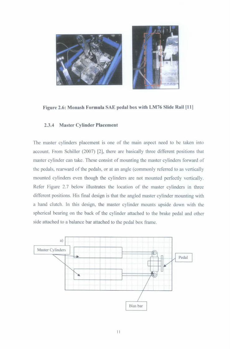
Figure 2.6: Monash Formula SAE pedal box with LM76 Slide Rail [111
2.3.4 Master Cylinder Placement
The master cylinders placement is one of the main aspect need to be taken into
account. From Schiller (2007) [2], there are basically three different positions that
master cylinder can take. These consist of mounting the master cylinders forward of
the pedals, rearward of the pedals, or at an angle (commonly referred to as vertically
mounted cylinders even though the cylinders are not mounted perfectly vertically.
Refer Figure 2.7 below illustrates the location of the master cylinders in three
different positions. His final design is that the angled master cylinder mounting with
a hand clutch. In this design, the master cylinder mounts upside down with the
spherical bearing on the back of the cylinder attached to the brake pedal and other
side attached to a balance bar attached to the pedal box frame.
II
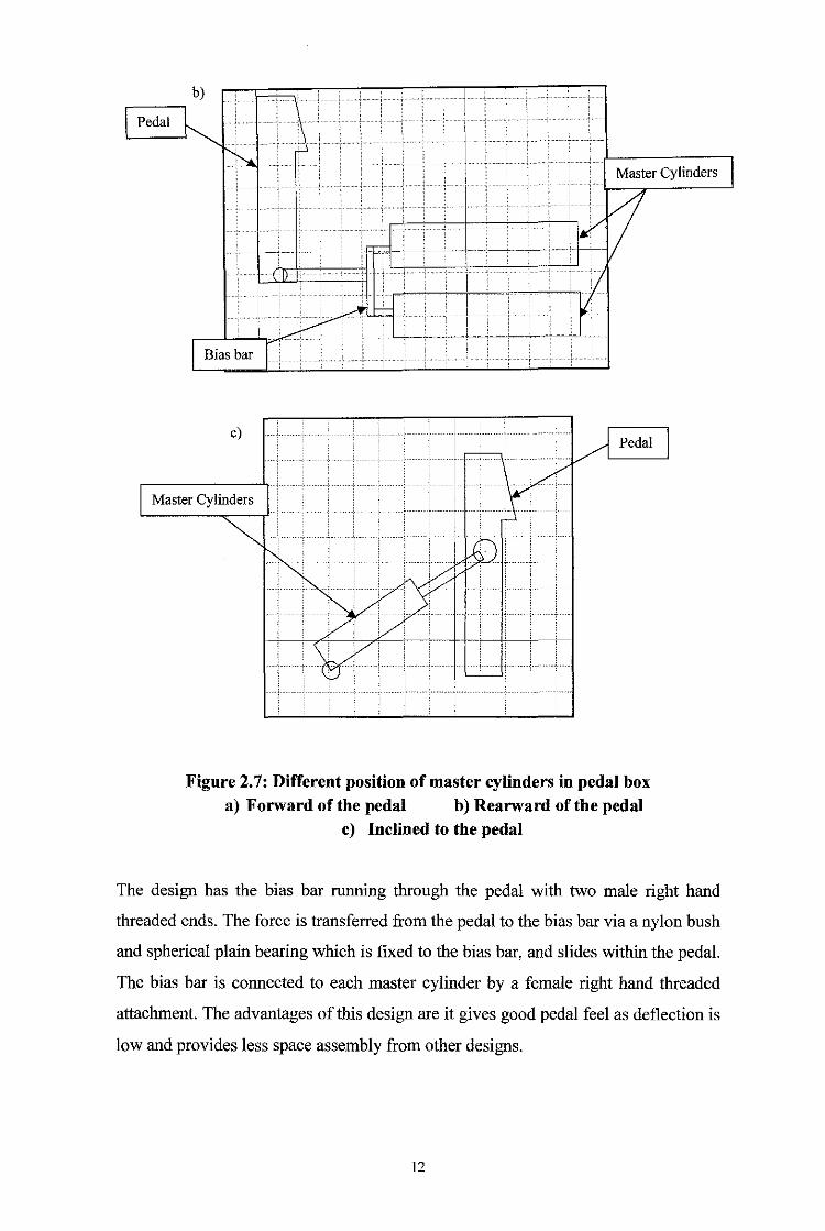
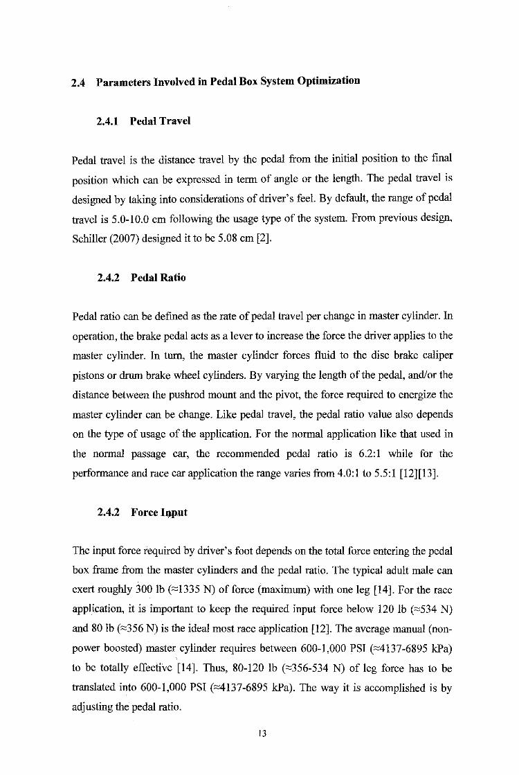
Figure 2. 7: Different position of master cylinders in pedal box a) Forward of the pedal b) Rearward ofthe pedal
c) Inclined to the pedal
The design has the bias bar running through the pedal with two male right hand
threaded ends. The force is transferred from the pedal to the bias bar via a nylon bush
and spherical plain bearing which is fixed to the bias bar, and slides within the pedal.
The bias bar is connected to each master cylinder by a female right hand threaded
attachment. The advantages of this design are it gives good pedal feel as deflection is
low and provides less space assembly from other designs.
12
2.4 Parameters Involved in Pedal Box System Optimization
2.4.1 Pedal Travel
Pedal travel is the distance travel by the pedal from the initial position to the final
position which can be expressed in term of angle or the length. The pedal travel is
designed by taking into considerations of driver's feel. By default, the range of pedal
travel is 5.0-10.0 em following the usage type of the system. From previous design,
Schiller (2007) designed it to be 5.08 em [2].
2.4.2 Pedal Ratio
Pedal ratio can be defmed as the rate of pedal travel per change in master cylinder. In
operation, the brake pedal acts as a lever to increase the force the driver applies to the
master cylinder. In turn, the master cylinder forces fluid to the disc brake caliper
pistons or drum brake wheel cylinders. By varying the length of the pedal, and/or the
distance between the pushrod mount and the pivot, the force required to energize the
master cylinder can be change. Like pedal travel, the pedal ratio value also depends
on the type of usage of the application. For the normal application like that used in
the normal passage car, the recommended pedal ratio is 6.2:1 while for the
performance and race car application the range varies from 4.0:1 to 5.5:1 [12][13].
2.4.2 Force ll)put
The input force required by driver's foot depends on the total force entering the pedal
box frame from the master cylinders and the pedal ratio. The typical adult male can
exert roughly 300 lb ("'1335 N) of force (maximum) with one leg (14]. For the race
application, it is important to keep the required input force below 120 lb ("'534 N)
and 80 lb ("'356 N) is the ideal most race application [12]. The average manual (non
power boosted) master cylinder requires between 600-1,000 PSI (~137-6895 kPa)
to be totally effective [14]. Thus, 80-120 lb ("'356-534 N) of leg force has to be
translated into 600-1,000 PSI (~137-6895 kPa). The way it is accomplished is by
adjusting the pedal ratio.
13
CHAPTER3
METHODOLOGY
3.1 Procedure Identification
Generally, the project can be divided into two parts. The scope of work for the first
part involves doing research about background study, understanding the theory and
work planning. The scope of work for the second part includes designing, simulation
process, stress-strain analysis and material selection. Below are the steps taken
towards the successful of the project.
a) Full understandings of the regulations and requirement of Formula SAE race
car specific on driver interface system mainly on pedal box system.
b) Study on theory understanding and parameters acquisitons of the component.
c) CAD design by using CA TIA
d) Analysis with focusing on material selection.
e) Study on kinematics and dynamics analysis of the system itself. The analysis
consists of equations derivation and iterations and comparison between the
analytical method and modeling simulation. Microsoft Excel is used first by
coding the formula and putting the values. Assumptions have been made by
considering all the possiblities
f) Simulate the design using ADAMS. The force distribution, pedal angle and
pedal travel of the system has been ploted to obtain the results.
g) For the improvement, further research and development has been discussed
and recommendations have been made in order to create the optimal result for
Formula SAE competition.
The procedure identification and has been summarized in Process Flow Chart
(see Appendix 2).
14

3.2 Tools and Equipments Required
The tools and equipments required for this project are;
a) CATIA
Some of the parameters involving the geometry are acquired using CA TIA.
Once the specifications are all set, the drawing and modeling will start take
place. CA TIA aided to give the 3D projection of the design to give better
understanding of the system. Then, FEA analysis was conducted by using the
functions in the same software.
b) MSCADAMS
MSC.ADAMS (Advanced Dynamic Analysis of Mechanical Systems) from
MSC Software is a software tool for simulation of motions in mechanical
systems. In this project, ADAMS View was used to do dynamics and
kinematics analysis. From this analysis, force or load distribution of the
pedals can be obtained by running the simulation.
c) Microsoft Excel
Microsoft Excel in this project is used to do the coding for the formulas,
calculation involving pedal box fundamental and mathematical equation.
d) Current UTP Formula SAE Pedal Box
The current UTP Formula SAE Pedal Box will be used as datum in this
project. All the analysis will be referring to this model initially and
improvement will be made to maximize the system performance.
The timeline and key milestones of the project can be summarized in the Gantt chart.
See Appendix 3.
15
3.3 Project Activities
The project consists of two maJor activities t.e. designing using CA TIA and
simulation process by ADAMS software. fhe designing process took place after all
parameters and specifications are obtained.
3.3.1 Designing Process
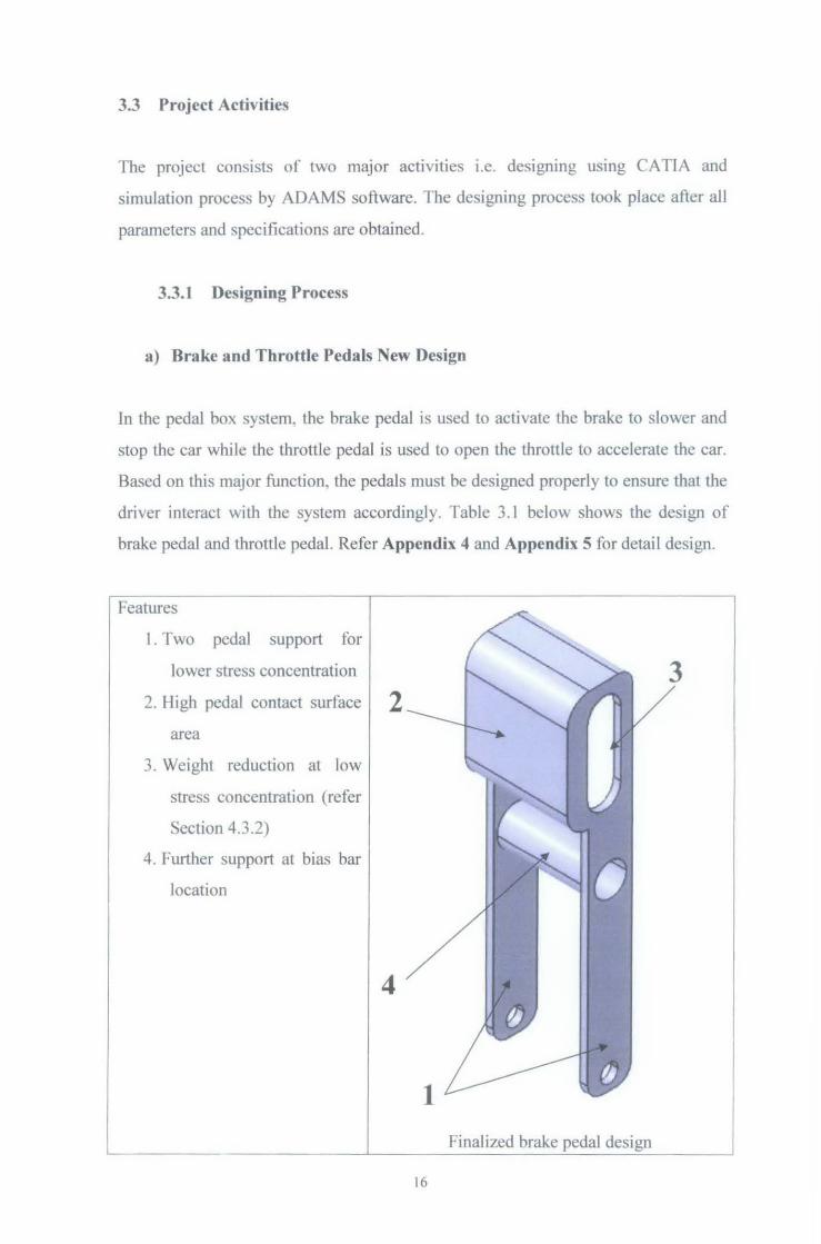
a) Brake and Throttle Pedals New Design
In the pedal box system. the brake pedal is used to activate the brake to slower and
stop the car while the throttle pedal is used to open the throttle to accelerate the car.
Based on this major function. the pedals must be designed properly to ensure that the
driver interact with the system accordingl}. Table 3.1 below shows the design of
brake pedal and throttle pedaL Refer Appendix 4 and Appendix 5 for detail design.
Features
I . Two pedal support for
lower stress concentration 3 2. High pedal contact surface 2
area
3. Weight reduction at low
stress concentration (refer
Section 4.3.2)
4. Further support at bias bar
location
4
Finalized brake pedal design ~------------------------~------------
16
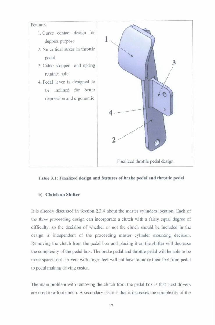
I Features
1. Curve contact design for
depress purpose
2. No critical stress in throttle
pedal
3. Cable stopper and spnng
retainer hole
4. Pedal lever is designed to
be inclined for better
depression and ergonomic
1
Finaliled throttle pedal design
Table 3.1: Finalized design and features of brake pedal and throttle pedal
b) Clutch on Shifter
It is already discussed in Section 2.3.4 about the ma<;ter cylinders location. Each of
the three proceeding design can incorporate a clutch with a fairly equal degree of
ditliculty, so the decision of whether or not the clutch should be included in the
design is independent of the proceeding master cylinder mounting decision.
Removing the clutch from the pedal box and placing it on the shifter will decrease
the complexity of the pedal box. The brake pedal and throttle pedal will be able to be
more spaced out. Drivers with larger feet will not have to move their feet from pedal
to pedal making driving easier.
The main prohlem with removing the clutch from the pedal box is that most drivers
are used to a foot clutch. A secondary issue is that it increases the complexity of the
17
shifter design. The solution from these problems is that the drivers must get
familiarized with the condition in the cockpit first before entering the competition. If
the drivers get enough time in the car, they may be able to get used to the hand
clutch.
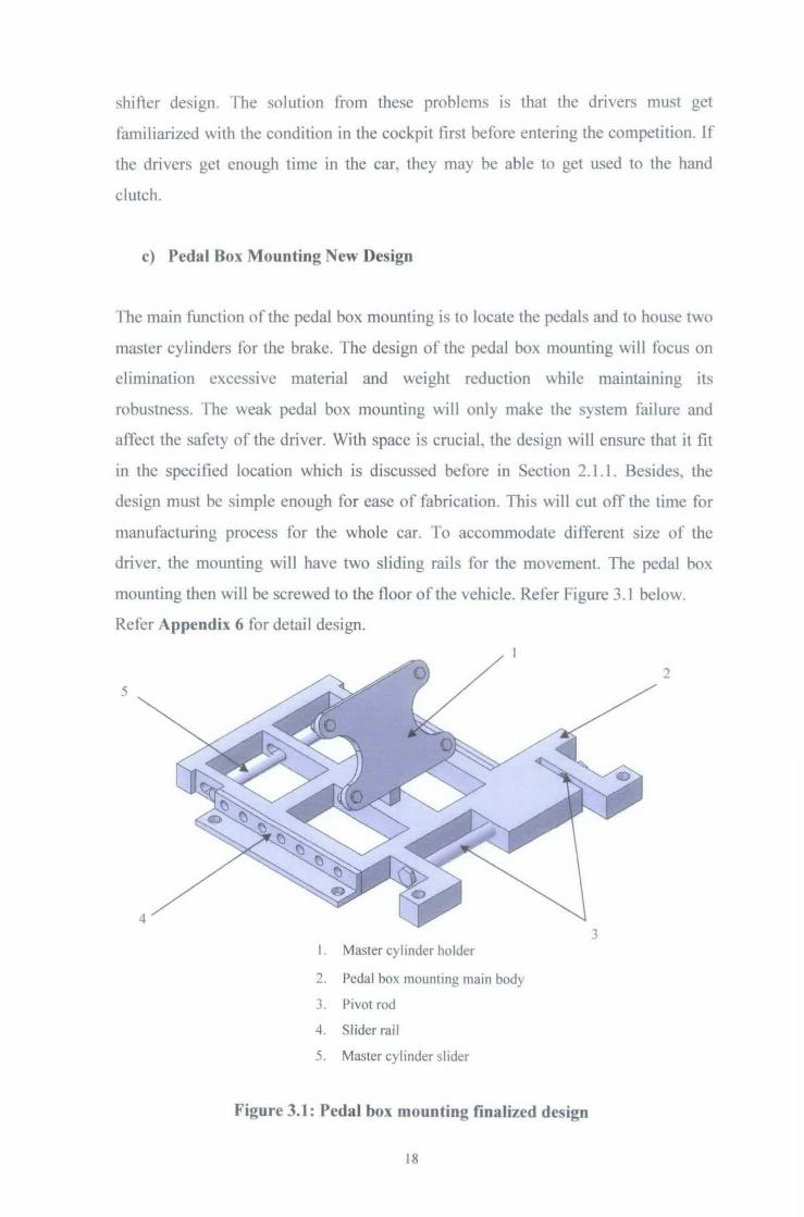
c) Pedal Box Mounting New Design
The main function of the pedal box mounting is to locate the pedals and to house two
master cylinders for the brake. The design of the pedal box mounting will focus on
elimination excessive material and weight reduction while maintaining its
robustness. I'he weak pedal box mounting will only make the system failure and
affect the safety of the driver. With space is crucial, the design will ensure that it fit
in the specified location which is discussed before in Section 2.1.1. Besides, the
design must be simple enough for ease of fabrication. This will cut off the time for
manufacturing process for the whole car. To accommodate different size of the
driver. the mounting will have two sliding rails for the movement. The pedal box
mounting then will be screwed to the floor of the vehicle. Refer Figure 3.1 below.
Refer Appendix 6 for detail design.
2 5
3 I. Master cylinder holder
2. Pedal box mounting main body
3. Pivot rod
4. Slider rail
5. Master cylinder slider
Figure 3.1: Pedal box mounting finalized design
18
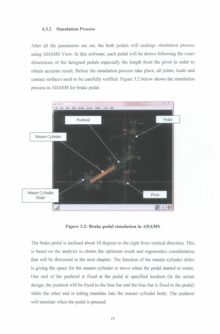
4.3.2 Simulation Process
After aJI the parameters are set, the both pedals will undergo simulation process
using ADAMS View. In this software, each pedal will be drawn following the exact
dimensions of the designed pedals especially the length from the pivot in order to
obtain accurate result. Before the simulation process take place, all joints, loads and
contact surfaces need to be carefully verified. Figure 3.2 below shows the simulation
process in ADAMS for brake pedal.
Master Cylinder Slider
Figure 3.2: Brake pedal simulation in ADAMS
The brake pedal is inclined about I 0 degrees to the right from vertical direction. This
is based on the analysis to obtain the optimum result and ergonomics consideration
that will be discussed in the next chapter. The function of the master cylinder slider
is giving the space for the master cylinder to move when the pedal started to rotate.
One end of the pushrod is fixed at the pedal at specified location (in the actual
design, the pushrod will be fixed to the bias bar and the bias bar is fixed to the pedal)
while the other end is letting translate into the master cylinder body. The pushrod
will translate when the pedal is pressed.
19
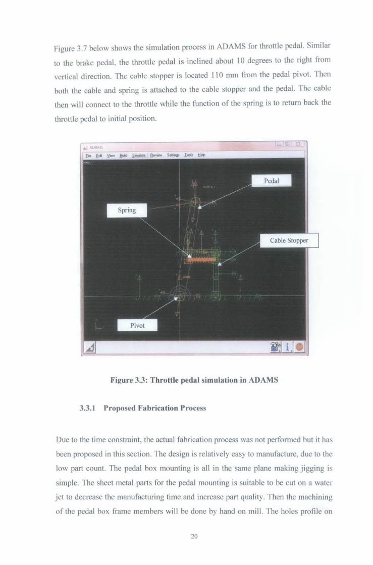
figure 3.7 below shows the simulation process in ADAMS for throttle pedal. Similar
to the brake pedal, the throttle pedal is inclined about l 0 degrees to the right from
vertical direction. The cable stopper is located 11 0 mm from the pedal pivot. Then
both the cable and spring is attached to the cable stopper and the pedal. rhe cable
then will connect to the throttle while the function of the spring is to return back the
throttle pedal to initial position.
Figure 3.3: Throttle pedal simulation in ADAMS
3.3.1 Proposed Fabrication Process
Due to the time constraint, the actual fabrication process was not performed but it has
been proposed in this section. The design is relative!) easy to manufacture, due to the
low part count. The pedal box mounting is all in the same plane making jigging is
simple. The sheet metal parts for the pedal mounting is suitable to be cut on a water
jet to decrease the manufacturing time and increase part quality. Then the machining
or the pedal box frame members will be done by hand on milL The holes profile on
20
the pedal box mounting should be drilled using EDM Drilling Machine. There will
be no problem to use EDM because the material that already selected for pedal box
mounting is electrically conductive (refer Section 4.2).
The both levers of throttle pedal and brake pedal and the cable stopper will use the
same method using water jet. The support at bias bar location will have a tube cut
into desired length and bearing pockets will use lathe to fabricate. The pedal pads can
be fabricating using Wire EDM. The profile first will be designing in AutoCAD
because the machine only can interact with the software. The design then will be
transferred to Wire EDM to cut the piece as per design. All the joints of the pedal
will use TIG welding process.
21
CHAPTER4
RESULTS AND DISCUSSION
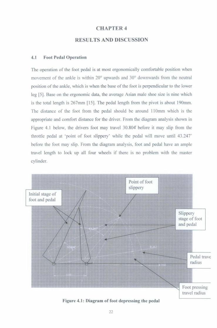
4.1 Foot Pedal Operation
The operation of the foot pedal is at most ergonomically comfortable position when
movement of the ankle is within 20° upwards and 30° downwards from the neutral
position of the ankle, which is when the base of the foot is perpendicular to the lower
leg [5]. Base on the ergonomic data, the average Asian male shoe size is nine which
is the total length is 267mm [15]. The pedal length from the pivot is about 190mm.
The distance of the foot from the pedal should be around 11 Omm which is the
appropriate and comfort distance for the driver. From the diagram analysis shown in
Figure 4.1 below, the drivers foot may travel 30.804' before it may slip lfom the
throttle pedal at ' point of foot slippery' while the pedal will move until 43.247"
before the foot may slip. From the diagram analysis, foot and pedal have an ample
travel length to Jock up aH four wheels if there is no problem with the master
cylinder.
Initial stage of foot and pedal
Figure 4.1: Diagram of foot depressing the pedal
22
Slippery stage of foot and pedal
The pedal contact surface area, to which the force is applied by the toot, is
considered optimal for occasional use when it has a length of 80mm [5].For the
height of the pedal pad, it is best to adjust it 8 inches from the floor [2].
The possible foot force applied to a foot pedal can be generated by using two
different muscle functions, ankle generated force or a leg generated force. Ank;le
generated force gives the driver greater control over the applied force, and will be
utilized for normal operation in the design of the brake pedal. The maximum force
generated from ankle rotation is about 600 N, however as the pedal angle will begin
at about 65° and finish at 45°, the percentage of maximum force will vary over the
pedal motion from l 00% at beginning to 83% at after 20° of pedal motion [16]. As
this is a maximum value, the design of the brake pedal must take into account the
muscle fatigue that would occur if this required for each brake pedal application. The
design of the brake pedal must also take into account the possible effects of leg force
being applied, under a driver panic situation. The maximum force possible when the
entire leg is used is at least 2100 N; however this requires the correct seating and
pedal position. For the angle of knee bend and thigh angle that the driver will have
when in the Formula SAE-A race car, the force from a brake application using the
entire leg will approximately be 38% of the maximum possible [17].This results in
the pedal being design to with stand infinite cyclic loading of eighty lbs (""356 N)
which is the ideal leg force requirement for race application [12]. This means that the
distributed force is equal to 4.45 N/mm. For the worst condition, which is the leg
force being applied, an amount of 800 N force will be taken into consideration.
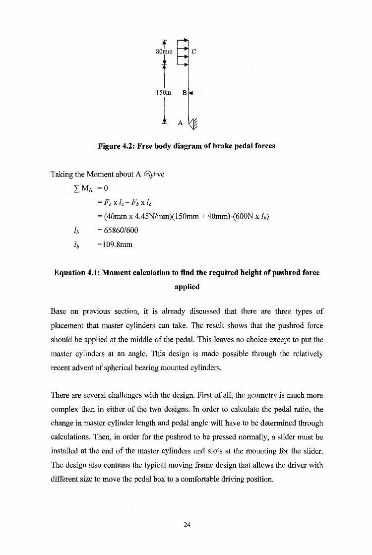
To correctly design a brake pedal, the basic moment calculations are used to
determine the increase in the force applied by driver's foot to a magnitude required
for effective brake system efficiency. The specifications given by the brake system
designer, approximated that a total force of 600 N would sufficiently operate the
car's brake system. This force will be achieved through mechanical advantage,
placing the point to which the total force is applied (point B) closer to the foot pad
(C), than the mean distance of the pedal pivot (point A). To calculate the required
distance from the pedal pivot to achieve the required total force, the moment is taken
about point A see Figure 4.2 and Equation 4.1.
23
t
T 150m
l Figure 4.2: Free body diagram of brake pedal forces
Taking the Moment about A l/'i).+ve
LMA =0
=Fcxlc-Fbxh
= (40mm x 4.45N/mm)(150mm + 40mm)-(600N x h)
h = 65860/600
lb =109.8mm
Equation 4.1: Moment calculation to find the required height ofpushrod force
applied
Base on prevtous section, it is already discussed that there are three types of
placement that master cylinders can take. The result shows that the pushrod force
should be applied at the middle of the pedal. This leaves no choice except to put the
master cylinders at an angle. This design is made possible through the relatively
recent advent of spherical bearing mounted cylinders.
There are several challenges with the design. First of all, the geometry is much more
complex than in either of the two designs. In order to calculate the pedal ratio, the
change in master cylinder length and pedal angle will have to be determined through
calculations. Then, in order for the pushrod to be pressed normally, a slider must be
installed at the end of the master cylinders and slots at the mounting for the slider.
The design also contains the typical moving frame design that allows the driver with
different size to move the pedal box to a comfortable driving position.
24
4.2 Material Considerations
The main objective of the material selection process is to find the material that can
provide the lightest weight yet will not break when an amount of stress have been
applied. The two types of material that have high potential for the design are steel
and aluminium. These two materials are used extensively in general fabrication as
they both have a reasonably low cost and good workability.
Steel would be a suitable material to manufacture a brake pedal, as it has good
strength and good fatigue properties; however for application in the Formula SAE-A
race car, weight considerations make is undesirable for use, as a lower strength light
weight material would be sufficient. Aluminium has a lower strength than steel;
however it still has good properties for implementation in a brake pedal. The major
benefit of aluminium over steel is the reduced weight as it is aluminium has a density
of 2.8 Mg/m3, compared to steel with a density of 7.7 Mg/m3, making aluminium
64% lighter than steel [18]. It has been decided that the part will use 6061-T6
aluminium, to create a low weight product and it has the following properties shown
in Table 4.1. The endurance limit will be used in the analysis of the aluminium brake
pedal as a fatigue failure could possible occur in this part. The part will be design for
infinite life, and the Fatigue strength for this situation was calculated using Equation
4.2 [19] to find a value of 88 MPa. Also included into the design of this part is a
factor of safety of 4, which will be used for the design of key braking parts.
For Aluminium S=llOx 1 x 1 x0.8
=88 Mpa
Eqnation 4.2: Fatigue Strength [19]
The material selected for the bias bar is a high carbon steel 4 340 (properties shown in
Table 4.1), as it is considered a high stress area and failure of this part would result in
a total system failure.
25
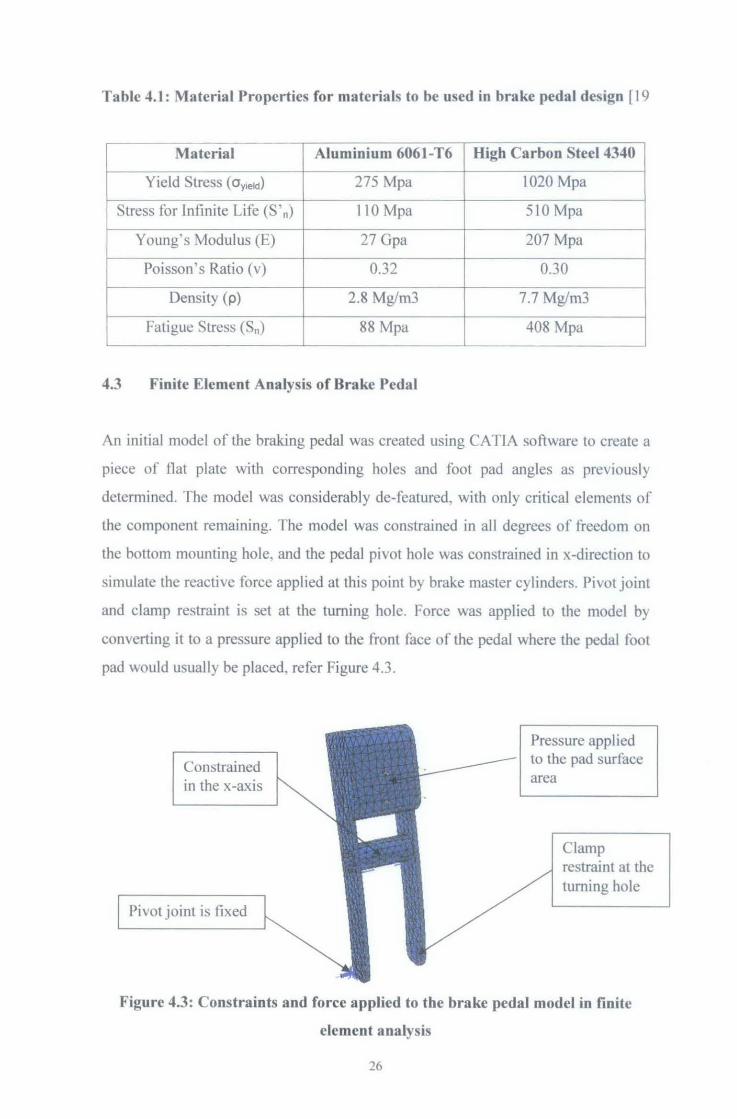
Table 4.1: Material Properties for materials to be used in brake pedal design [19
Material Aluminium 6061-T6 High Carbon Steel 4340
Yield Stress ( Oyield) 275 Mpa 1020 Mpa
Stress for Infinite Life (S ' n) 110 Mpa 510 Mpa
Young's Modulus (E) 27 Gpa 207 Mpa
Poisson's Ratio (v) 0.32 0.30
Density (p) 2.8 Mg/m3 7.7 Mg/m3
Fatigue Stress (Sn) 88 Mpa 408 Mpa
4.3 Finite Element Analysis of Brake Pedal
An initial model of the braking pedal was created using CATIA software to create a
piece of flat plate with corresponding holes and foot pad angles as previously
determined. The model was considerably de-featured, with only critical elements of
the component remaining. The model was constrained in all degrees of freedom on
the bottom mounting hole, and the pedal pivot hole was constrained in x-direction to
simulate the reactive force applied at this point by brake master cylinders. Pivot joint
and clamp restraint is set at the turning hole. Force was applied to the model by
converting it to a pressure applied to the front face of the pedal where the pedal foot
pad would usually be placed, refer Figure 4.3.
Constrained in the x-axis
Pivot joint is fixed
Pressure applied to the pad surface area
Clamp restraint at the turning hole
Figure 4.3: Constraints and force applied to the brake pedal model in finite
element analysis
26
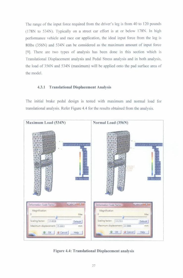
The range of the input force required from the driver's leg is from 40 to 120 pounds
( 178N to 534N). Typically on a street car effort is at or belo"" 178N. In high
performance vehicle and race car application, the ideal input force from the leg is
801bs (356N) and 534N can be considered as the maximum amount of input force
[91. There are two types of analysis has been done in this section which is
Translational Displacement analysis and Pedal Stress analysis and in both analysis.
the load of 356N and 534N (maximum) will be applied onto the pad surface area of
the model.
4.3.1 Translational Displacement Analysis
The initial brake pedal design is tested with maximum and normal load for
translational analysis. Refer Figure 4.4 for the results obtained from the analysis.
Maximum Load (534N)
Magnifiution 0 Ma•
xaling factor 1130028 Default I MaXImum disp au~ment; r:l3-=-s.ooo=3-~~--m-m
Cancel J Help I
Normal Load (356N)
L>eformati011 Scale
Magnification 0
xa.ing fa<tor: IBJ511
• 0
MaXImum displacement f235996 ____ mm
Cancel l Help_j
Figure 4.4: Translational Displacement analysis
27
f-or the max1mum load (534N), the max1mum displacement is 35.0003mm with
scaling factor of 13.0028, resulting the translational displacement of 2.692mm. For
the normal load (356N) applied, the maximum displacement and scaling factor are
23 .5996mm and 13.151 I. fhis produced the translational displacement of
1.7944mm. ·r his small values of displacement of 3.00mm is acceptable because in
thickness of 0.250 inch (6.35 mm) or less, it has elongation of 8% while the
elongation at break is at 12% [20][21]. Furthermore, the pedal will be pivoted at the
turning point and it will move in the same direction of the displacement. fhus the
displacement will be neglected.
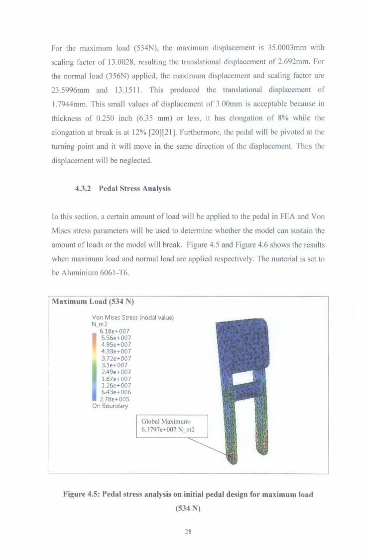
4.3.2 Pedal Stress Analysis
In this section. a certain amount of load will be applied to the pedal in FEA and Yon
Mises stress parameters will be used to determine whether the model can sustain the
amount of loads or the model will break. Figure 4.5 and Figure 4.6 shows the results
when maximum load and normal load are applied respectively. The material is set to
be Aluminium 6061-T6.
Maximum Load (534 N)
Von M1ses Stress (nodal value) N_m2
6.18e+007 5.56e+007 4.9Se+007 4.33e+007 3.72e+007 3.1e+007 2.49e+007 1.87e+007 1.26e+007 6.43e+006 2.78e+OOS
On Boundary
Global Maximum-6.1797e+007 N m2
Figure 4.5: Pedal stress analysis on initial pedal design for maximum load
(534 N)
28

Normal Load (356 N)
Von M ises Stress (nodal value) N_m2
4.12e+007 3.7le+007 3.3e+007 2.89e+007 2.48e+007 2.07e+007 1.66e+007 1.25e+007 8.39e+006 4.29e+006 1.85e+OOS
On Boundary
Global Maximum-4.1198e+007 N m2
Figure 4.6: Pedal stress analysis on initial pedal design for normal load (356 N)
The global maximum stress for maximum load (543 N) is 61.8 MPa and for the
notmalload (356N) is 41.2 MPa. From the Appendix 7, the Tensile Yield Strength
value for Aluminium 6061-T6 is 275 Mpa. This value is way too high compared to
the maximum stress for both conditions. Therefore, it is concluded that the brake
pedal design is safe although worst condition load is applied.
From the analysis result, it is found that most ofthe location ofthis initial design was
under little or no stress, especially at the upper part of the pedal which is farther than
clamped turning hole. This was expected as it complies with the stress distribution
for beams in bending, whjch states that the outer most fibres from the neutral axis of
a material will under goes the maximum stress when placed in bending. Due to this
case, the pedal need to undergo a little changes in order to obtain the utmost efficient
design.The revised design is that hole has been made at the both side of the plate at
surface pad. The benefit of this modification is the associated weight reduction with
the removal of materials at low stress area. Refer Figure 4.7 below.
29
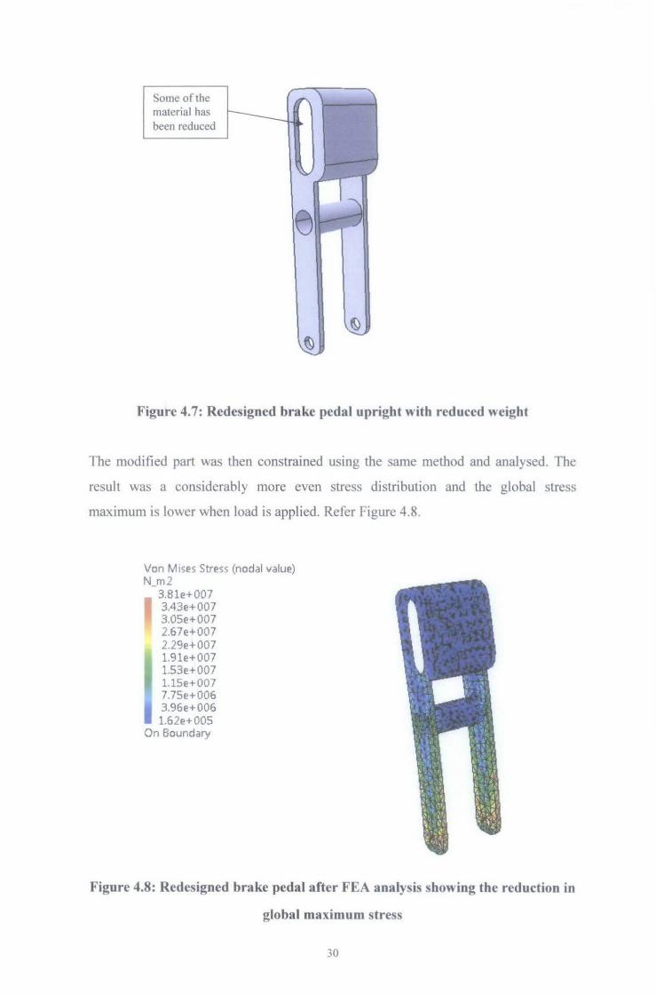
Some of the material has been reduced
Figure 4.7: Redesigned brake pedal upright with reduced weight
The modified part was then constrained using the same method and analysed. The
result was a considerably more even stress distribution and the global stress
maximum is lower when load is applied. Refer Figure 4.8.
Von M1ses Stress (nodal value) N_m2
3.8le+007 3.43e+007 3.05e+007 2.67e+007 2.29e+007 1.9le+007 1.53e+007 1.15e+007 7.75e+006 3.96e+006 1.62e+005
On Boundary
Figure 4.8: Redesigned brake pedal after FEA analysis showing the reduction in
global maximum stress
30
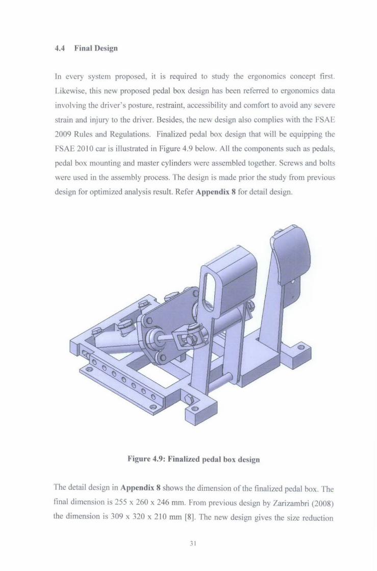
4.4 Final Design
In every system proposed, it is required to study the ergonom1cs concept first.
Likewise, this new proposed pedal box design has been referred to ergonomics data
involving the driver' s posture, restraint, accessibility and comfort to avoid an} severe
strain and injury to the driver. Besides, the new design also complies with the FSAh
2009 Rules and Regulations. Finalized pedal box design that will be equipping the
FSAE 20 I 0 car is illustrated in Figure 4. 9 below. All the components such as pedals,
pedal box mounting and master cylinders were assembled together. Screws and bolts
were used in the assembly process. The design is made prior the study from previous
design for optimized analysis result. Refer Appendix 8 for detail design.
Figure 4.9: Finalized pedal box design
The detail design in Appendix 8 shows the dimension of the finalized pedal box. The
tina! dimension is 255 x 260 x 246 mm. From previous design by Zarizambri (2008)
the dimension is 309 x 320 x 2 10 mm f8]. The new design gives the size reduction
31
about 33 percents from the previous design based on the length and width of the
pedal box. The major contribution to this result is because the clutch pedal was put at
the shifter. This will reduces the complexity of the pedal box and the throttle pedal
and brake pedal will be more spaced out. The drivers with bigger foot will have no
problem in depressing the pedals. The smaller size in pedal box also gives more
option to the chassis designer to locate the pedal box in the front bodywork as the
pedal box location must not beyond the front bulkhead of the car. But the increasing
in the height is because of the pedal length. Base on the ergonomic data, the average
Asian male shoe size is nine which is the total length is 267 mm. Therefore the pedal
pad's midpoint to the pedal pivot must be around 190 mm in length to comply with
this data.
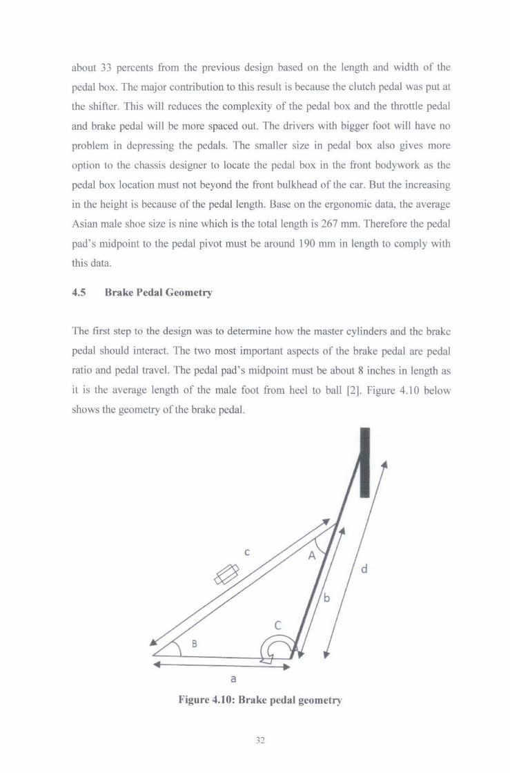
4.5 Brake Pedal Geometry
The first step to the design was to determine how the master cylinders and the brake
pedal should interact. The two most important aspects of the brake pedal are pedal
ratio and pedal travel. The pedal pad's midpoint must be about 8 inches in length as
it is the average length of the male foot from heel to ball [2]. Figure 4.10 below
shows the geometry of the brake pedal.
a
Figure 4.10: Brake pedal geometry
32
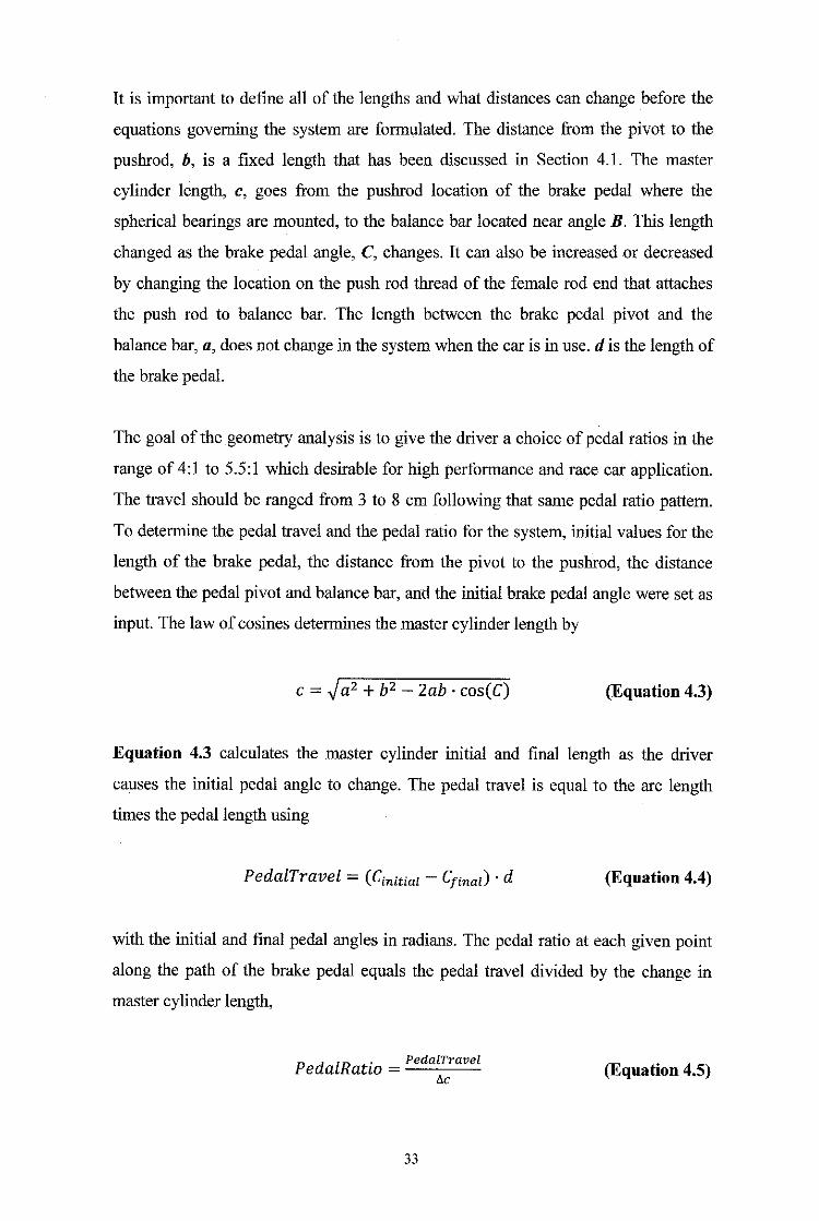
It is important to define all of the lengths and what distances can change before the
equations governing the system are formulated. The distance from the pivot to the
pushrod, b, is a fixed length that has been discussed in Section 4.1. The master
cylinder length, c, goes from the pushrod location of the brake pedal where the
spherical bearings are mounted, to the balance bar located near angle B. This length
changed as the brake pedal angle, C, changes. It can also be increased or decreased
by changing the location on the push rod thread of the female rod end that attaches
the push rod to balance bar. The length between the brake pedal pivot and the
balance bar, a, does not change in the system when the car is in use. dis the length of
the brake pedal.
The goal of the geometry analysis is to give the driver a choice of pedal ratios in the
range of 4:1 to 5.5:1 which desirable for high performance and race car application.
The travel should be ranged from 3 to 8 em following that same pedal ratio pattern.
To determine the pedal travel and the pedal ratio for the system, initial values for the
length of the brake pedal, the distance from the pivot to the pushrod, the distance
between the pedal pivot and balance bar, and the initial brake pedal angle were set as
input. The law of cosines determines the master cylinder length by
c = -Ja2 + b2- Zab · cos(C) (Equation 4.3)
Equation 4.3 calculates the master cylinder initial and final length as the driver
causes the initial pedal angle to change. The pedal travel is equal to the arc length
times the pedal length using
PedalTravel = ( Cinitial - Cfinaz) • d (Equation 4.4)
with the initial and final pedal angles in radians. The pedal ratio at each given point
along the path of the brake pedal equals the pedal travel divided by the change in
master cylinder length,
P d lR t. PedalTravel e a a w =
f1c (Equation 4.5)
33
The next step is to determine where the pedal stops which is the point at which all
four wheels lock up and the input force required by the driver at the point. The force
from a master cylinder that enters the pedal box is
F=t:.c·A·P (Equation 4.6)
where A is the cross-sectional area of the master cylinder and P is the pressure in the
master cylinder at lock up. The total force entering the pedal box frame from the
master cylinders is
Ftotal = Ffront + Frear (Equation 4. 7)
where both unit front and rear system must be taken into consideration. The input
force required by the driver's foot is
p. = Ftotal mput PedalRatio
(Equation 4.8)
The calculations to determine the optimal pedal box geometry were done in
Microsoft Excel. Initial values for the length of the brake pedal, the distance from the
pivot to the pushrod, the distance between the pedal pivot and balance bar, and the
initial brake pedal angle were inserted. The function simulates the pedal moving
through an arc and computes pedal ratio and input force required.
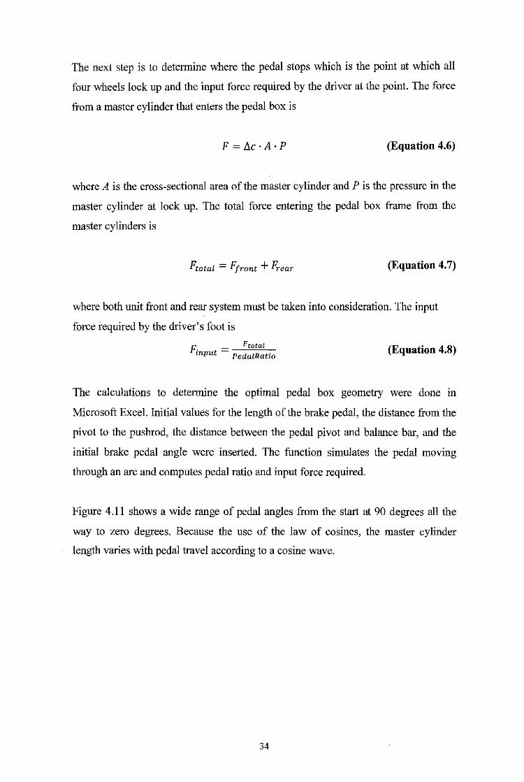
Figure 4.11 shows a wide range of pedal angles from the start at 90 degrees all the
way to zero degrees. Because the use of the law of cosines, the master cylinder
length varies with pedal travel according to a cosine wave.
34
_, _________ ,,_, _____________ , ___ , _____________ , _____ , ______ 1
[ _ Change in Master Cylinder vs Pedal Travel " .. 'I
I ,, ,------------·--------------------------- , ____ , --- --
1 5! _______________________________ I I " 1, /___.- I
I i 4~--------------/~-------- _______ ,_, ___ , , r-------7-----------------, _____ _
~ 1 ~-------------·--- --!:.. ________ ,, _________ -----------·---~-·-------·--·-,_, __ 1 I /_,.--
u i, 1/ 1 1_, ______ .}'/ ______________________ -----------·--------···-----------·---
/
I ',~~ 15 2(< 2S 3(\
Pedal Trav(!-1 ((:fl'j)
L------------------· . _________ , _________ , _____ ,
Figure 4.11: Change in Master Cylinder vs Pedal Travel for 90 to 0 degrees
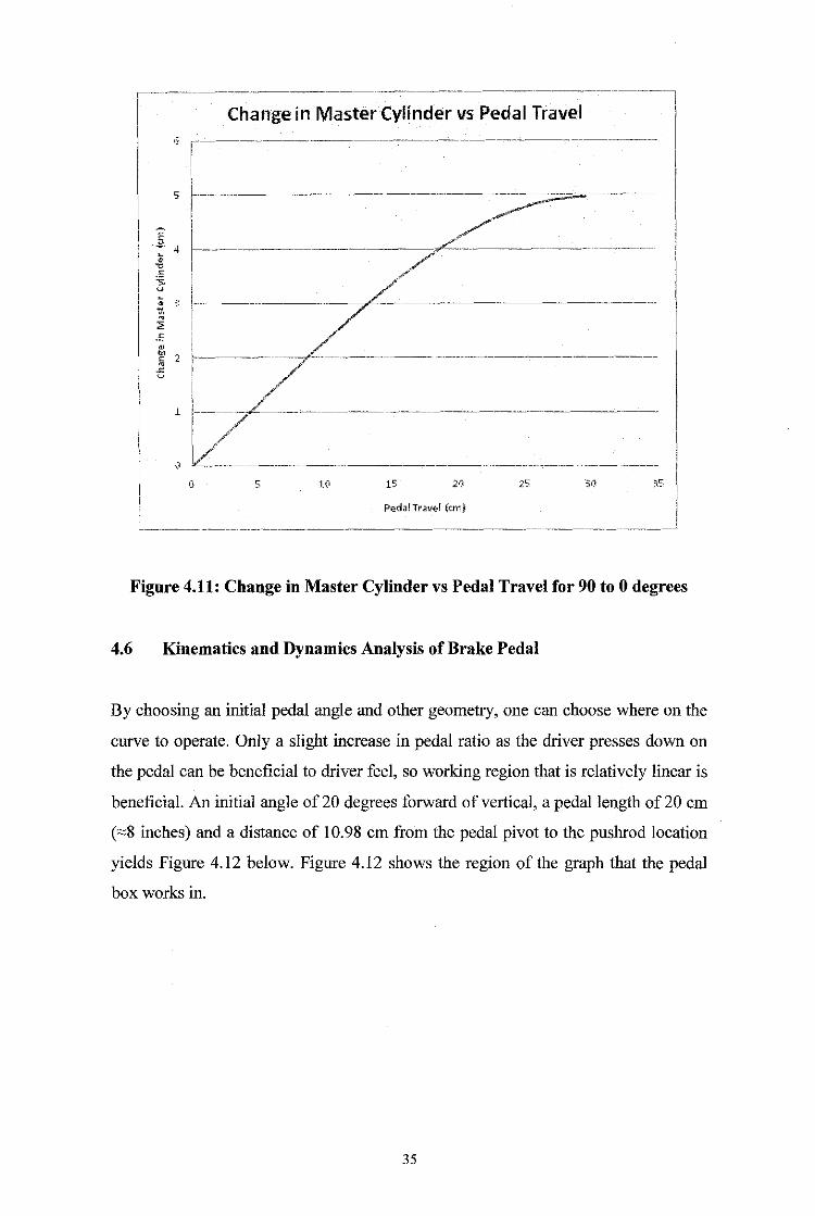
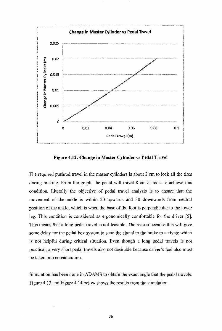
4.6 Kinematics and Dynamics Analysis of Brake Pedal
By choosing an initial pedal angle and other geometry, one can choose where on the
curve to operate. Only a slight increase in pedal ratio as the driver presses down on
the pedal can be beneficial to driver feel, so working region that is relatively linear is
beneficial. An initial angle of 20 degrees forward of vertical, a pedal length of 20 em
("'8 inches) and a distance of 10.98 em from the pedal pivot to the pushrod location
yields Figure 4.12 below. Figure 4.12 shows the region of the graph that the pedal
box works in.
35
Change in Master Cylinder vs Pedal Travel
O.D25 ,----···········-·········-·-····· . ···············-·············· •··· ··-··-·-·-··--·
E 0.02 !·-·········-··--······· - --··················--··· •········-·····
0.01
~ 1:
"' ti 0.005
o L __ _ ----· ···---····· --- ·-····· ····---········
0 0.02 0.04 0.06 0.08 0.1
Pedal Travel (m)
Figure 4.12: Change in Master Cylinder vs Pedal Travel
The required pushrod travel in the master cylinders is about 2 em to lock all the tires
during braking. From the graph, the pedal will travel 8 em at most to achieve this
condition. Literally the objective of pedal travel analysis is to ensure that the
movement of the ankle is within 20 upwards and 30 downwards from neutral
position of the ankle, which is when the base of the foot is perpendicular to the lower
leg. This condition is considered as ergonomically comfortable for the driver [5].
This means that a long pedal travel is not feasible. The reason because this will give
some delay for the pedal box system to send the signal to the brake to activate which
is not helpful during critical situation. Even though a long pedal travels is not
practical, a very short pedal travels also not desirable because driver's feel also must
be taken into consideration.
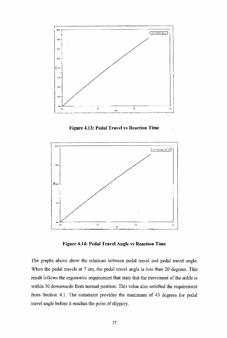
Simulation has been done in ADAMS to obtain the exact angle that the pedal travels.
Figure 4.13 and Figure 4.14 below shows the results from the simulation.
36
---------------- ·----1
I -~"-""·-'I I
l CQ.U
I "" 1
II: 1C.D
~.~~: __________ ___:_ ___ ~, _____ :_ ___________ :'_1
Figure 4.13: Pedal Travel vs Reaction Time
~ I I '" I I I I I
l-~-~" ___________ .:_· ___ ~~------: _______________ ~:__j Figure 4.14: Pedal Travel Angle vs Reaction Time
The graphs above show the relations between pedal travel and pedal travel angle.
When the pedal travels at 7 em, the pedal travel angle is less than 20 degrees. This
result follows the ergonomic requirement that state that the movement of the ankle is
within 30 downwards from normal position. This value also satisfied the requirement
from Section 4.1. The constraint provides the maximum of 43 degrees for pedal
travel angle before it reaches the point of slippery.
37
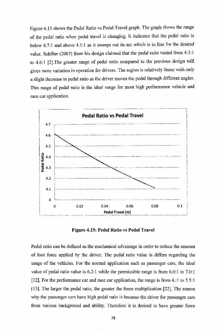
Figure 4.15 shows the Pedal Ratio vs Pedal Travel graph. The graph shows the range
of the pedal ratio when pedal travel is changing. It indicates that the pedal ratio is
below 4.7:1 and above 4.1:1 as it sweeps out its arc which is in line for the desired
value. Schiller (2007) from his design claimed that the pedal ratio varied from 4.3:1
to 4.6:1 [2].The greater range of pedal ratio compared to the previous design will
gives more variation in operation for drivers. The region is relatively linear with only
a slight decrease in pedal ratio as the driver moves the pedal through different angles.
This range of pedal ratio is the ideal range for most high performance vehicle and
race car application.
Pedal Ratio vs Pedal Travel
4.7
4.6
4.5
0 ~ 4.4 a: iii -g 4.3
"" 4.2
4.1
4
0 0.02 0.04 0.06 0.08 0.1
Pedal Travel (m)
Figure 4.15: Pedal Ratio vs Pedal Travel
Pedal ratio can be defmed as the mechanical advantage in order to reduce the amount
of foot force applied by the driver. The pedal ratio value is differs regarding the
usage of the vehicles. For the normal application such as passenger cars, the ideal
value of pedal ratio value is 6.2:1 while the permissible range is from 6.0:1 to 7.0:1
[12]. For the performance car and race car application, the range is from 4.:1 to 5.5:1
[13]. The larger the pedal ratio, the greater the force multiplication [22]. The reason
why the passenger cars have high pedal ratio is because the driver for passenger cars
from various background and ability. Therefore it is desired to have greater force
38
multiplication. But the higher value of pedal ratio also resulted in higher pedal travel
[22]. For the race car application, this condition is not desired because the driver
tends to push the pedal abruptly during high speed to slower down the car.
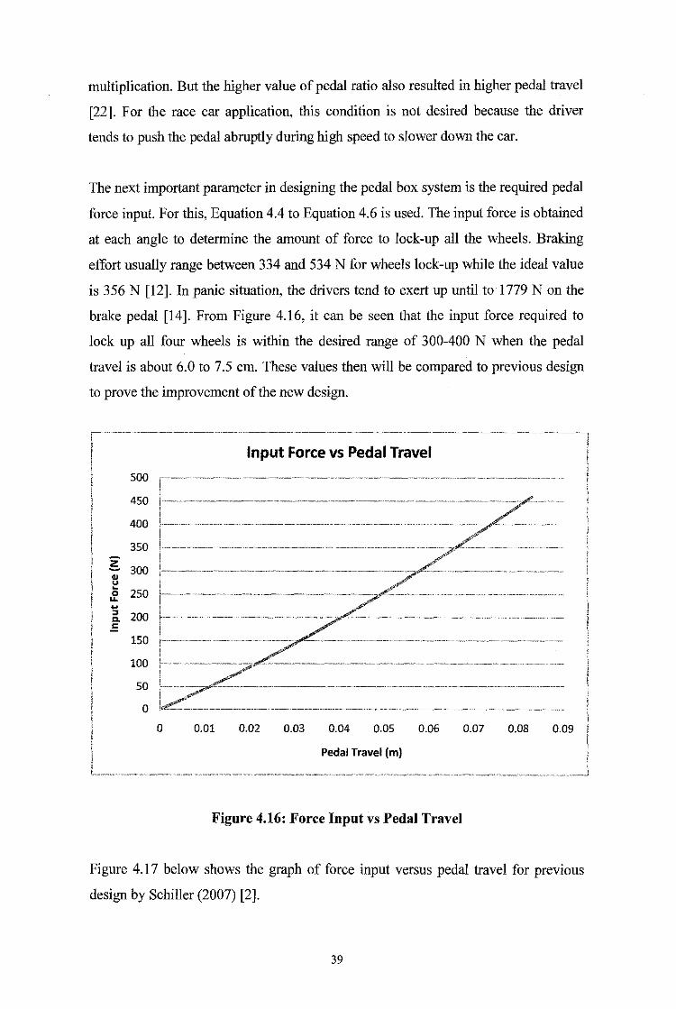
The next important parameter in designing the pedal box system is the required pedal
force input. For this, Equation 4.4 to Equation 4.6 is used. The input force is obtained
at each angle to determine the amount of force to lock-up all the wheels. Braking
effort usually range between 334 and 534 N for wheels lock-up while the ideal value
is 356 N [12]. In panic situation, the drivers tend to exert up until to 1779 N on the
brake pedal [14]. From Figure 4.16, it can be seen that the input force required to
lock up all four wheels is within the desired range of 300-400 N when the pedal
travel is about 6.0 to 7.5 em. These values then will be compared to previous design
to prove the improvement of the new design.
~··············-···-···-·· ·-···-·················---··-···--·-· ·-······-·-········- ..
Input Force vs Pedal Travel
500
450
400
350
z OJ
300 !····-·······-······························ ·---········-···--···
u ~
250 0 ... ~ ::J 200 a. .5
150
100
50
0
0 0.01 0.02 0.03 0.04 0.05 0.06 0.07 0.08 0.09
Pedal Travel (m)
Figure 4.16: Force Input vs Pedal Travel
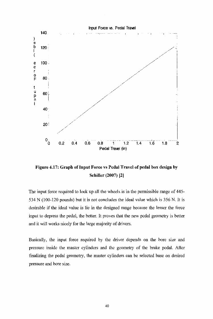
Figure 4.17 below shows the graph of force input versus pedal travel for previous
design by Schiller (2007) [2].
39
Input Force vs. Pedal Travel 140
s b 120 .--"/ I ( /
/,/
e 100 / /' .... /
c /
r /
/ 0 / F 80 /
/ /
/ /
t /// u 60 p //,.
n // I
/ /
40 //_,/
/ /
/
" /
/
20' ~···
/ / -/
0 '
--· ··'··· .. --- -- -------- .. ------ ___ ...J ___
0 0.2 0.4 0.6 0.8 1 1.2 1.4 1.6 1.8 2 Pedal Travel (in)
Figure 4.17: Graph oflnput Force vs Pedal Travel of pedal box design by
Schiller (2007) [2]
The input force required to lock up all the wheels is in the permissible range of 445-
534 N (100-120 pounds) but it is not concludes the ideal value which is 356 N. It is
desirable if the ideal value is lie in the designed range because the lesser the force
input to depress the pedal, the better. It proves that the new pedal geometry is better
and it will works nicely for the large majority of drivers.
Basically, the input force required by the driver depends on the bore size and
pressure inside the master cylinders and the geometry of the brake pedaL After
finalizing the pedal geometry, the master cylinders can be selected base on desired
pressure and bore size.
40
4.7 Kinematics and Dynamics Analysis of Throttle Pedal
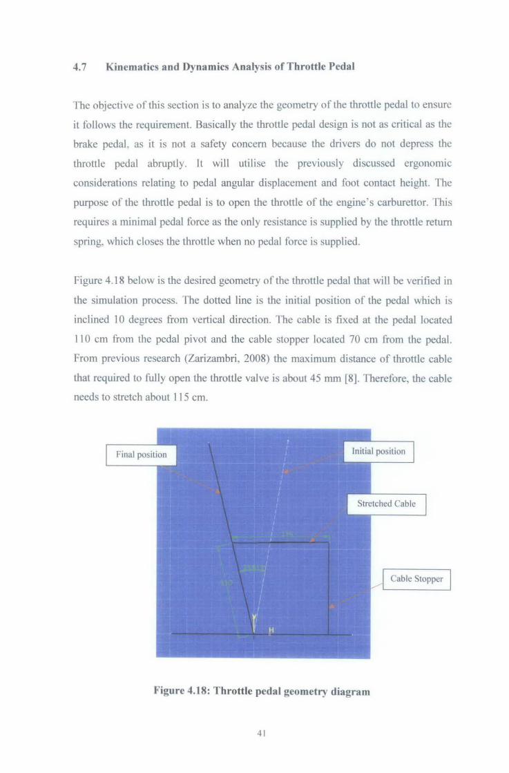
The objective of this section is to analyze the geometry of the throttle pedal to ensure
it follows the requirement. Basically the throttle pedal design is not as critical as the
brake pedaL as it is not a safety concern because the drivers do not depress the
throttle pedal abruptly. It will utilise the previously discussed ergonomic
considerations relating to pedal angular displacement and foot contact height. The
purpose of the throttle pedal is to open the throttle of the engine· s carburettor. This
requires a minimal pedal force as the only resistance is supplied by the throttle return
spring, which closes the throttle when no pedal force is supplied.
Figure 4.18 below is the desired geometry of the throttle pedal that will be verified in
the simulation process. fhe dotted line is the initial position or the pedal which is
inclined 10 degrees from vertical direction. The cable is fixed at the pedal located
1 1 0 em from the pedal pivot and the cable stopper located 70 em from the pedal.
From previous research (Zarizambri, 2008) the maximum distance of throttle cable
that required to fully open the throttle valve is about 45 mm [8]. Therefore, the cable
needs to stretch about 1 15 em.
Cable Stopper
Figure 4.18: Throttle pedal geometry diagram
41
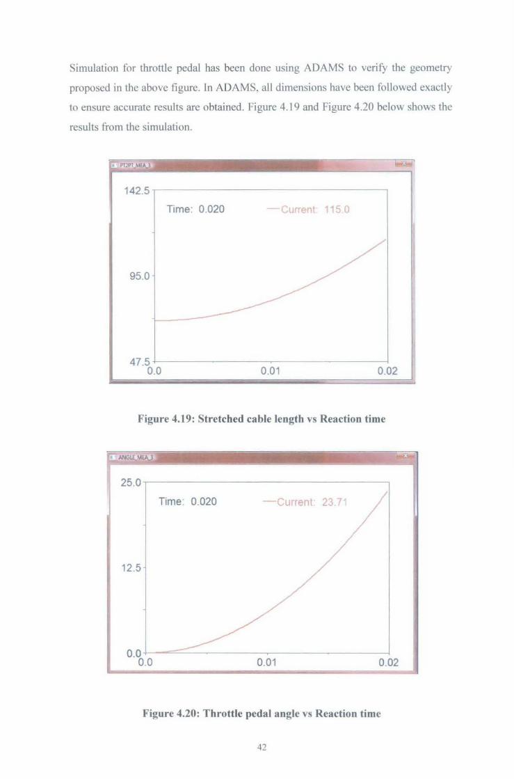
Simulation for throttle pedal has been done using ADAMS to verify the geometry
proposed in the above tigure. In ADAMS, all dimensions have been followed exactly
to ensure accurate results are obtained. Figure 4.19 and Figure 4.20 below shows the
results from the simulation.
142. 5~----------------,
Time: 0 020 - Current 115 0
95.0
47.5 +---------0.0 0.01 0.02
Figure 4.19: Stretched cable length vs Reaction time
--- - -- -
-· - . ~ _- --- --- -
25.0~----------------------~
Time 0.020 -Current. 23.71
12.5
0.0 4--==-~------.----0.0 0.01 0.02
Figure 4.20: Throttle pedal angle vs Reaction time
42
The first graph shows the length of the stretched cable when the pedal is depressed.
With specified spring stiffness coefficient and force input, it follows the desired
value of cable stretched length. The second graph shows the angle. 23.71 degrees
that the pedal traveled when the cable is stretched to 115 em. rhis is similar to the
value from the desired geometry figure which is 23.61 degrees. This verified that the
throttle will be working well as desired.
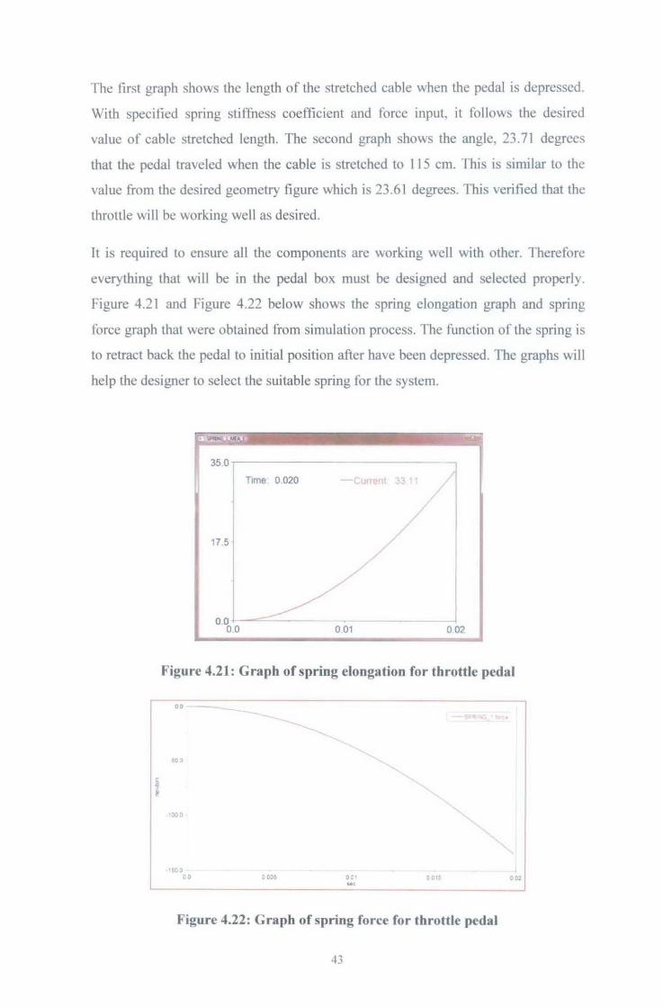
It is required to ensure all the components are working well with other. Therefore
everything that will be in the pedal box must be designed and selected properly
Figure 4.21 and Figure 4.22 below shows the spring elongation graph and spring
force graph that were obtained from simulation process. The function of the spring is
to retract back the pedal to initial position after have been depressed. The graphs will
help the designer to select the suitable spring for the system.
35.0.------------------.,
I 17.5
0 .0 0.0
T1me 0 020 urrent <j 1
/ ,
_/ /
0 01
/
/ I
/
0 02
Figure 4.21: Graph of spring elongation for throttle pedal
0 0 -
·~o co 001 .. , 0015
Figure 4.22: Graph of spring force for throttle pedal
43
. oo:
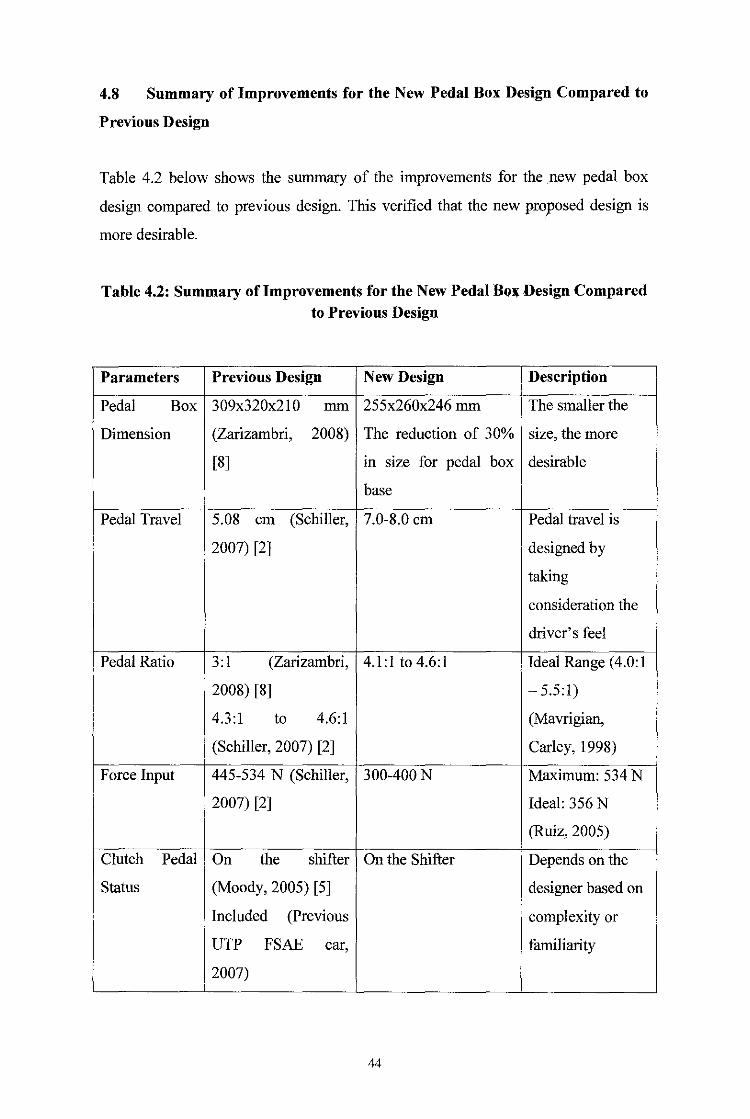
4.8 Summary of Improvements for the New Pedal Box Design Compared to
Previous Design
Table 4.2 below shows the summary of the improvements for the new pedal box
design compared to previous design. This verified that the new proposed design is
more desirable.
Table 4.2: Summary oflmprovements for the New Pedal Bo~ Design Compared to Previous Design
Parameters Previous Design New Design Description
Pedal Box 309x320x210 mm 255x260x246 mm The smaller the
Dimension (Zarizambri, 2008) The reduction of 30% size, the more
[8] in size for pedal box desirable
base
Pedal Travel 5.08 em (Schiller, 7.0-8.0 em Pedal travel is
2007) [2] designed by
taking
consideration the
driver's feel
Pedal Ratio 3: I (Zarizambri, 4.1:1 to4.6:1 Ideal Range ( 4.0: I
2008) [8] - 5.5:1)
4.3:1 to 4.6:1 (Mavrigian,
(Schiller, 2007) [2] Carley, 1998)
Force Input 445-534 N (Schiller, 300-400N Maximum: 534 N
2007) [2] Ideal: 356 N
(Ruiz, 2005)
Clutch Pedal On the shifter On the Shifter Depends on the
Status (Moody, 2005) [5] designer based on
Included (Previous complexity or
UTP FSAE car, familiarity
2007)
44
CHAPTERS
CONCLUSION AND RECOMMENDATION
5.1 Conclusion
The new design shows the reduction of the pedal box size about 30 percents from
previous design. The pedal range is 7.0-8.0 em. The result is obtained after taking
considerations of driver's feel. Pedal ratio range is 4.0:1 to 4.7:1 which is in the ideal
range. The input force to lock up all four wheels is within desired range 400-500 N.
After taking consideration the complexity of the pedal box, the clutch is located on
the shifter. These results prove the improvement of the new pedal box system.
Therefore the objectives are achieved.
The implementation of the new pedal box system design will improve the
performance of UTP FSAE. The project concluded for design decisions, part
selection, material selection, as well as provide the all of the analysis to back up the
decisions. The project that involves ergonomic study, material selection, stress-strain
analysis, kinematic and dynamic analysis and fabrication process will optimized the
design for the FSAE car usage.
5.2 Recommendations
The technology is expanding; therefore there is always room for improvement. It is
important that the design contains several innovations as it is important to stay ahead
of the curve in the competition and if the design will be used as a building block for
future year's designs, it must contain new concepts that will take a while for other
teams to catch up. For future development, the pedal box system should be fabricated
and implemented on the car itself to see the efficiency of the system. The testing of
the car should be done early to give time for improvise from the feedbacks.
45
REFERENCES
[!] 2009 Formula SAE Rules (2008). Society of Automotive Engineers, USA.
(2] Schiller, B. W. (2007) 2007 Formula SAE Pedal Box. Bachelor of Science
thesis, Department of Mechanical Engineering Massachusetts Institute of
Technology, Cambridge, Massachusetts, USA.
[3] Enomoto, H., Miyazaki, Y., Mizuno, H., Hirano, E., K.itayama, S., Yamazaki,
K., et a!. (2007). Development of CFRP Monocoque Front Impact Attenuator
for FSAE with VaRTM. Society of Automotive Engineers of Japan, Inc.
[4] Wagner, Dan. http://dsr.racer.net/brake bias.htm
[5] Moody, B. J. (2005) Control and Instrumentation for USQ Formula SAE-A
Race Car. Bachelor of Engineering(Mechanical) and Bachelor of
Business(Logistics and Operation) thesis, Faculty of Engineering and
Surveying University of Southern Queensland, Toowoomba, Queensland,
Australia.
[6] http:/ /www.wikipedia.org/
[7] Enomoto, H., Morita, H., Fukunaga, Y. and Uota, N. (2007) Simplification of
the Shift/Clutch Operations for the Formula SAE Vehicles. Society of
Automotive Engineers of Japan, Inc.
[8] Ahmad, Z. (2008) Design and Analysis of a Pedal Box System for a Small
Race Car. Bachelor of Engineering (Hans) (Mechanical Engineering) thesis,
Mechanical Engineering Progranune Universiti Teknologi Petronas, Tronoh,
Perak, Malaysia.
[9] The Eastman Kodak Company. (1983). Ergonomic Design for People at Work,
Van Nostrand Reinhold, New York.
[I 0] Nakanishi, Y., Nethery, V. (1999) Anthropometric Comparison between
Japanese and Caucasian American Male University Students. Department of
Science, Kobe University, Japan.
[11] Gordon, R. (2005) Monash Motorsport Newsletter. Monash University,
Australia.
[12] Ruiz, S. Brake Pedal Setup and Dual Master Cylinder Installation Guide.
(2005).StopTech.
[13] Mavrigian, M., Carley, L. W. (1998) Brake Systems: OEM & Racing Brake
Technology. (1st ed).The Penguin Putnam Inc.
46
[14) Scraba, W. (2000-2009) autoMedia.com
[15] http://www.averageshoesize.com
[16) Staniforth, A. (2001) Race and Rally Car Source Book. (4'h ed).Haynes
Publishing.
[17) Kraemer, K. Kraemer, H., Kraemer-Elbert, K., (2001), Ergonomics How to
Design for Ease and Efficiency, Prentice Hall, Upper Saddle River, New
Jersey.
[18) Askeland, D, (2001), The Science and Engineering of Materials, (3rd ed),
Nelson Thomes Ltd, Cheltenham, UK.
[19) Juvinall, R. C., Marshek, K. M .. (2000). Fundamentals of Machine Component
Design. (3'd ed). John Wiley & Sons.
[20) http://en.wikipedia.org/wiki/Von Mises yield criterion
[21) http:/ /screem.engr.scu.edu/artemis/system/mech/al data.html
[22) http://www. j btmotorsport.comlbrake-facts.html
47
APPENDICES
APPENDIX 1 -Ergonomic Data
Table 1 Phy-::ique fAbsolttte n~eas·.trements.l of y'oung :apanese and Amer~can males
Character btics
~-Iei:;h: (em; Weight (kg) Si.tting Height (em) Sl-.olllder-Elbow length (em) =:.tbow-Wrist length (em)
Thi£h lengu (em.) C.:.lf l.<?.ngth (em) ?cot length (c.m) Neck girth :crJ) Chest girth (ur .. ) 3i::-eps gird·. (em) ~·crearm glrtl: (em)
AbdJninal girth (em) ~Hnnck» girrh :em: Thi.gh g:rth (SlY.)
Cdf gtrth (em)
.Japanese
1718-5.4 G2 1 - 5.8 927-3.8 37 6- 1.5 2G 2- 1.0
36.0- 1.5 33.8 - 1.6 25 8- 1.4 35 9- 1.3 870-4.3 266-2.0 25.9- 17 72 5 - 3.7 ~0? - ? g
53.1 - J.G 36.5- 2.9
Mean - SD. '-\1,mn-Whltr.ey's U tests were used.
48
Amer~can Dlffere:-.ce p
180.6 - ' 7 8.3 0.0001 ..... 78.6 - 9.: l i3. 5 0.0001 945 - 2.: 1.8 0.0948 42.4 - l.5 4 8 I) 0009 29.3 - 1.9 3.1 O.OOIJI' 40.9 - 3.: 4 9 0.0001 -·10.0 - 2.G 6.2 0 0001 28.2 - !.5 2.4 0. 000 1 33.6 - ? ' .... I) 2.7 1).0002'
100.: - 6.0 13.1 0.0001 3l.2 - 3.: 4.6 0. 0001 29.2 - 20 3.3 1). 00(11 84.9 - 5.- 12.4 0.0001
~" g - s 0 CJG (J 011(11 '
5G.7 - 4 ,; J.O 0.0094 38.8 - 2.8 2.3 0.0118
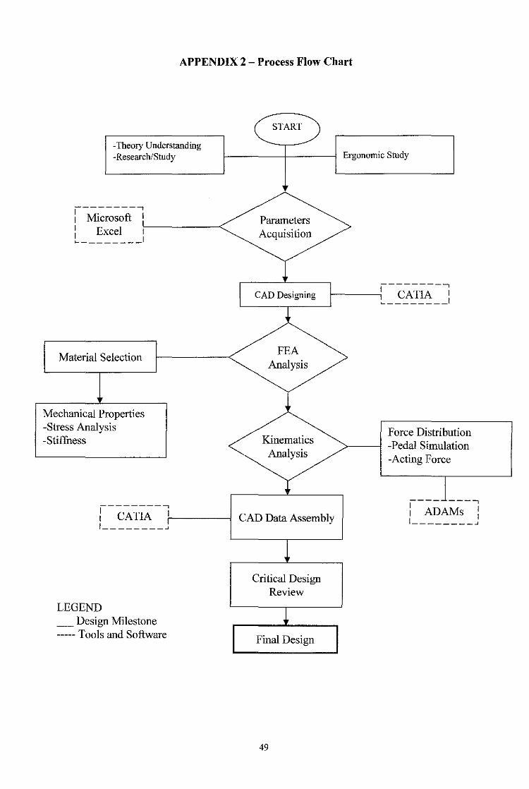
APPENDIX 2 - Process Flow Chart
-Theory Understanding -Research/Study
----------, l Microsoft l l Excel f---1 ---------<-.. .__ _ _____ I
Material Selection
Mechanical Properties -Stress Analysis -Stiffness
----------, : CATIA :-1 ------i I ________ .J
LEGEND __ Design Milestone -----Tools and Software
START
Parameters Acquisition
Ergonomic Study
--------....., 1------;1 CA TIA 1
._ ________ I
FEA Analysis
Kinematics Analysis
CAD Data Assembly
Critical Design Review
Final Design
49
Force Distribution -Pedal Simulation -Acting Force
---- ---...., : ADAMs : I ________ ...J
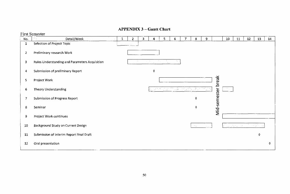
APPENDIX 3- Gantt Chart First Semester
No. Detail/Week 14
1 Selection of Project Topic
2 Preliminary research Work
3 Rules Understanding and Parameters Acquisition
4 Submission of preliminary Report 0
..>< 5 Project Work rc
(]) ,_ ..c
6 Theory Understanding ,_ I I (]) ..... V)
7 Submission of Progress Report 0 (])
E (]) V)
8 Seminar 0 ' ~ 9 Project Work continues
2:
10 Background Study on Current Design
11 Submission of Interim Report Final Draft 0
12 Oral presentation 0
50
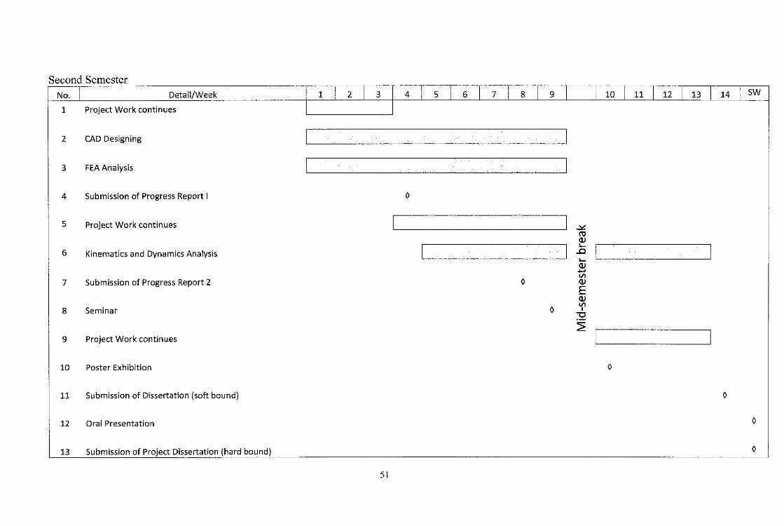
Second Semester No. I Detail/Week 1 I 2 I 3 4 I s I 6 I 7 I 8 I 9 I I 1o I 11 I 12 I 13 I 14 I sw
1 Project Work continues
2 CAD Designing I
3 FEA Analysis I
4 Submission of Progress Report I 0
5 Project Work continues l .:>~! ro (])
6 Kinematics and Dynamics Analysis I I .c I l ..... (]) ..... Vl
7 Submission of Progress Report 2 0 (])
E (])
8 Seminar Vl
0 ' ""0
9 Project Work continues ~I I
10 Poster Exhibition 0
11 Submission of Dissertation (soft bound) 0
12 Oral Presentation 0
13 Submission ofl'_roject Dissertation (hard bound) 0
51
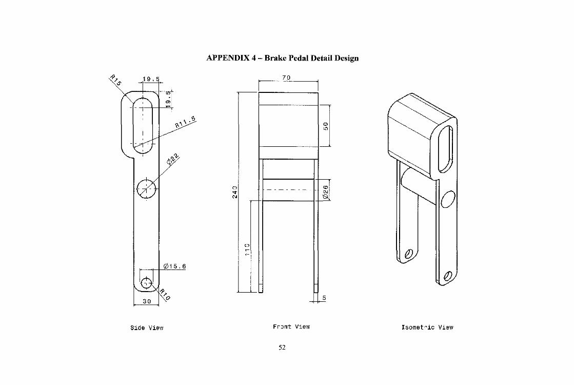
-9)' 6'
19.5
_,_I I I ~I
,.,\·"
~cv'"
015.6
1~-s>)'
30 0
Side View
APPENDIX 4 - Brake Pedal Detail Design
D ... "'
D --
~
70
"' -------" ~
- f-
Front View
52
0
{!)
1/1
Isometric View
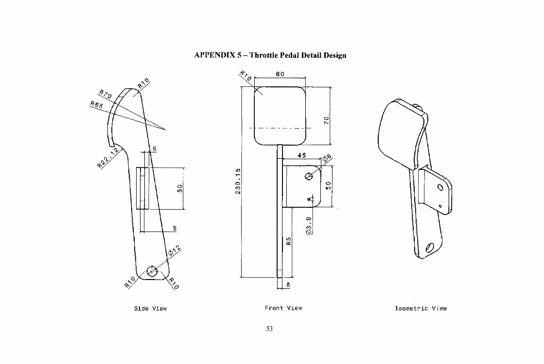
""'" '""': ~·
5
0
"'
rlt'"'
.'2Y"' ~r- \:o
Side View
APPENDIX 5 - Throttle Pedal Detail Design
>?. 60
~ - -
"' ~ 0
"' "'
-
~
-------- -
./
45
~ .. <»
"' &
"' "'
1-6
>----
Front View
53
a ,.._
I~
0 If)
g/
Isometric View

= t>l) ·~
"' ... ~ -·~ .. ..... ... ~
-:.:-~ t>l) .~ = ,.
·~ u ..... ·~ = ~ = ~
w = " ~ 0
" ~ - .,. = "' 1:!:1 -..
"C ... ~ I ~
~ ...... ~ z foil ~ ~
<
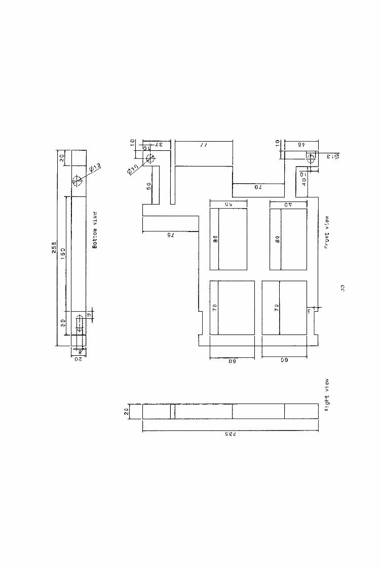
0
;;t ~--
.
- -t;t-LS +-
-~~
<\j!C..;:_ ,~y
0
"'
~
' "' "' 0 N
"' -
.I
0 ffft ~' I
-~ 0(.
I ll
u I
Sl 0
"'
[
I
u~ I
09 09
"' >
" "
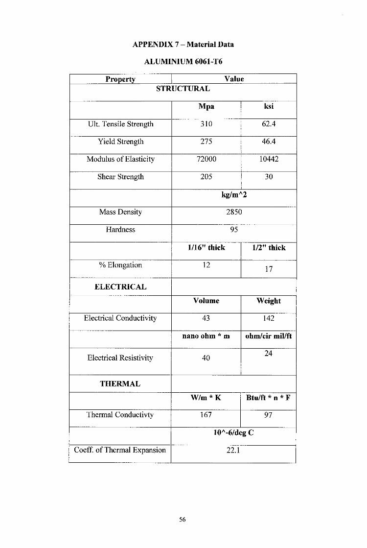
APPENDIX 7- Material Data
ALUMINIUM 6061-T6
Property Value STRUCTURAL
Mpa
Ult. Tensile Strength 310
Yield Strength 275
Modulus of Elasticity 72000
Shear Strength 205
ksi
62.4
46.4
10442
30
kgfmA2
Mass Density 2850
Hardness 95
1116" thick 112" thick
% Elongation 12 17
ELECTRICAL
Volume Weight
Electrical Conductivity 43 142
nano ohm* m ohm/cir mil/ft
Electrical Resistivity 40 24
THERMAL
W/m*K Btulft * n * F
Thermal Conductivty 167 97
lOA-6/deg C
Coeff. of Thermal Expansion 22.1
56
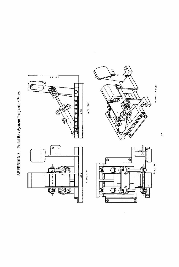
S5' ~tl
r;-.
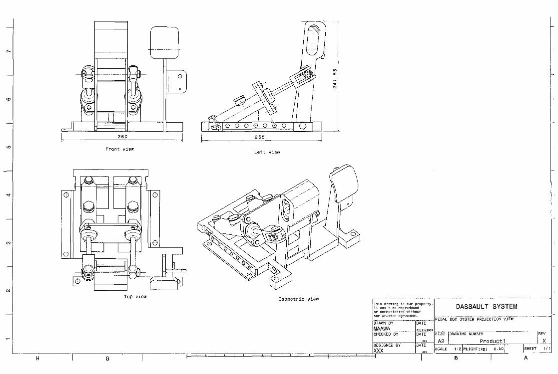
"
"'
"'
"
"'
"'
___ , ____
-----
I 0
I ' I
~- 260 ___ _ ~ Front view
0
0
Top view
I
~! ~
"'
e1fo / I I II I l I ~ ~ ~ ~ ~ ~ 0 0 I n I I __ 255
Left view
Isometric view·•
L
-- -- 1-ThlS drawing is our property. It can't oe repruducad
~:r C~~:~~;~a!;~e:!~~~~t . ·- . -~·--·-·-· ""'- "--.- -·---- ----~-· -- ---- -l-PEDAL BOX SYSTEM PROJECTION VIEW
DRAWN BY DATE
MAAWA _ o1 111 12ooQ CHECKED BY- DATE~ SIZE I DRAWING NUM~ -- --- --- -·" -~REV
m A2 Product1 X DESIGNED BY DATE --------XXX ) xxx scALE 1 21WEIGHT(kg) o.oo) FE~T -----~--'-1
DASSAULT SYSTEM
H I G I r 1 I B I A