Embed Size (px)
Citation preview
DESIGN AND ANALYSIS OF A PISTON FOR COMPRESSED NATURAL GAS (CNG)
ENGINE
SULAIMAN BIN ALIAS
UNIVERSITI MALAYSIA PAHANG
2
DESIGN ANALYSIS OF A PISTON FOR COMPRESSED NATURAL GAS (CNG) ENGINE
SULAIMAN BIN ALIAS
A report submitted in partial fulfilment of the requirements for the award of degree in
Bachelor of Mechanical Engineering with Automotive Engineering
Faculty of Mechanical Engineering UNIVERSITI MALAYSIA PAHANG
NOVEMBER 2008
3
SUPERVISOR’S DECLARATION
We hereby declare that we have checked this project and in our opinion this project is
satisfactory in terms of scope and quality for the award of the degree of Bachelor of
Mechanical Engineering with Automotive/Manufacturing*
Signature
Name of Supervisor: Prof Madya Dr Rosli Bin Abu Bakar
Position: Dean of Faculty of Mechanical Engineering
Date: 10 November 2008
Signature
Name of Co-Supervisor: Abdul Rahim Bin Ismail
Position: Lecture
Date: 10 November 2008
Signature
Name of Panel:
Position:
Date: 10 November 2008

4
STUDENT’S DECLARATION
I hereby declare that the work in this thesis is my own except for quotations and
summaries which have been duly acknowledged. The thesis has not been accepted
for any degree and is not concurently submitted for award of other degree.
Signature
Name: SULAIMAN BIN ALIAS
ID Number: MH05067
Date: 10 November 2008

5
ACKNOWLEDGEMENTS
First of all, I would like to thank my advisor Mr Abdul Rahim Bin Ismail for
his assistance in completing the PSM project. For those who have assisted I on
experimental work successfully, the suggestions and encourage have helped me in all
time, beginning from the concept design until completing analysis piston process and
in writing the report. Without his opinion and ideas it would be difficult for me to
complete and success in this project. Besides that, I would like to appreciate those
who gave me the possibility to complete this project. As a student, I accept all the
guidance given by my advisor. During this project, I have encountered so many
problems. Without them, I would not have made it through.
I would also like to acknowledge with much appreciation to the crucial role
of Dean Faculty of Mechanical Engineering, Associate Prof. Dr Rosli Bin Abu
Bakar, for his advice and instruction toward finishing my project. Especially to my
friends who took in this project by giving great idea in designing the Piston, using
Solidwork and Algor software.
I would like to thank my family for their continuous support and confidence
in my effort. They inspires me for what I have achieved today most importantly, is
their guidance and motivation, in order for me to become a worthy person for the
religion, race and state.
6
ABSTRACT
Engine pistons are one of the most complex components among all
automotive or other industry field components. The engine can be called the heart of
a car and the piston may be considered the most important part of an engine. There
are lots of research works proposing for engine pistons, new geometries, materials
and manufacturing techniques, and this evolution has undergone with a continuous
improvement over the last decades and required thorough examination of the
smallest details. Notwithstanding all these studies, there is huge number of damaged
pistons. Damage mechanisms have different origins and are mainly wear,
temperature, and fatigue related. Among the fatigue damages, thermal fatigue and
mechanical fatigue, either at room or at high temperature, play a prominent role.
This work is concerned only with the analysis of fatigue-damaged pistons.
Pistons from diesel engines will be analyzed. Damages initiated at the crown, ring
grooves, pin holes and skirt are assessed. A compendium of case studies of fatigue-
damaged pistons is presented. An analysis of both thermal fatigue and mechanical
fatigue damages is presented and analyzed in this work.
A linear static stress analysis, using “Algor works”, is used to determine the
stress distribution during the combustion. Stresses at the piston crown and pin holes,
as well as stresses at the grooves and skirt as a function of land clearances are also
presented. A fractographic study is carried out in order to confirm crack initiation
sites.

7
ABSTRAK
Piston enjin adalah merupakan komponen yang complex di dalam bidang
automotif atau dalam bidang komponen-komponen industri. Enjin boleh dipanggil
sebagai hati untuk sebuah kereta dan piston boleh juga di ketegorikan perkara yang
amat penting dalam bahagian enjin. Terdapat ramai pengkaji yang mengkaji tentang
piston enjin, geometri terbaru, bahan dan teknik pemprosesan dan pengkembangan
ini telah berterusan berkembang hingga lebih terperinci. Walaupun pengkaji masih
lagi mengkaji tentang piston enjin, kini masih banyak piston yang rosak. Mekanisme
kerosakan mempunyai pelbagai titik permulaan dan kebanyakannya adalah haus,
suhu dan kelesuan.
Projek ini hanya tertumpu kepada analisis kesan keatas kerosakan kelesuan
dan mengkaji tahap ketahanan piston kesan daripada suhu dan tekanan di dalam
pembakaran dalaman enjin. Piston ini diambil daripada enjin diesel dan diubah suai
agar boleh digunakan di dalam CNG enjin. Tempat yang paling kerap berlakunya
kerosakan seperti pada permukaan atas piston dan dinding piston. Satu ujikaji
mengenai kelesuan haba dan kelesuan mekanikal kerosakan di kaji.
8
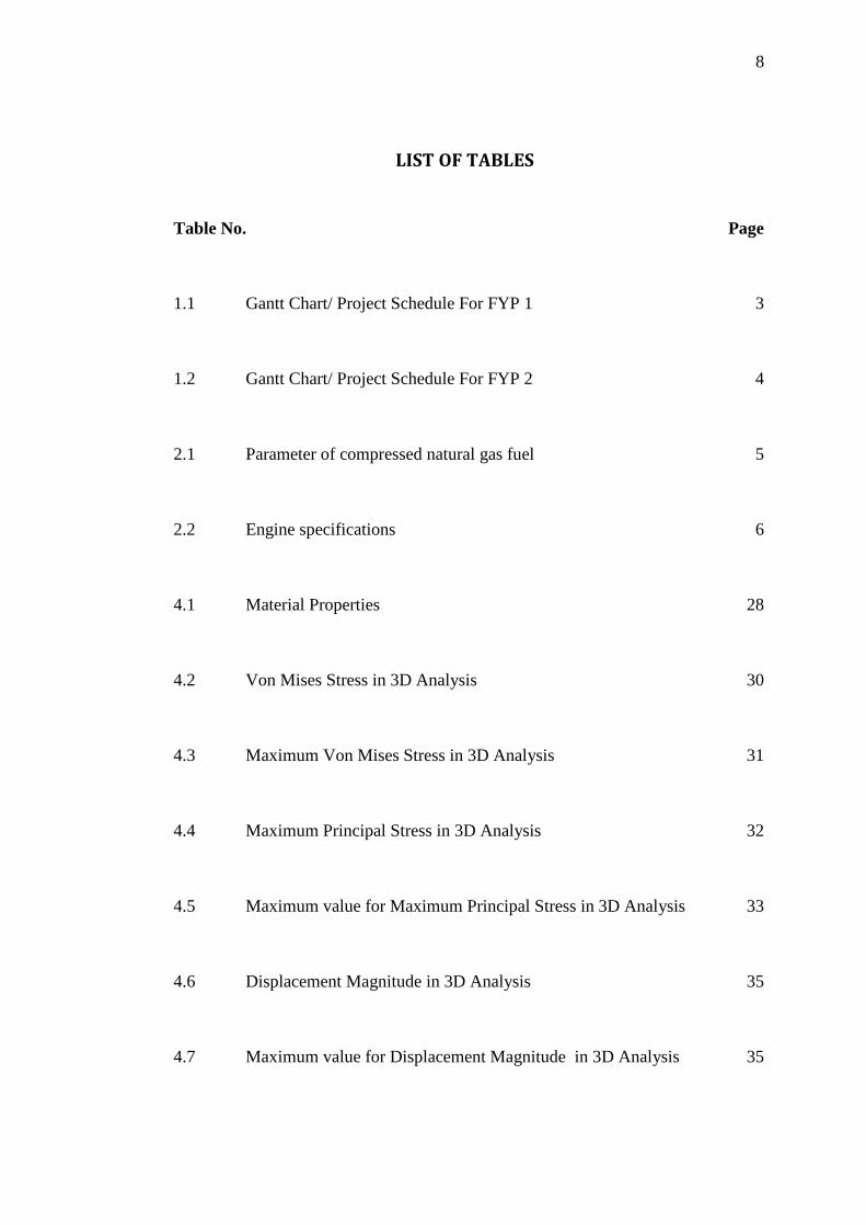
LIST OF TABLES
Table No. Page
1.1 Gantt Chart/ Project Schedule For FYP 1 3
1.2 Gantt Chart/ Project Schedule For FYP 2 4
2.1 Parameter of compressed natural gas fuel 5
2.2 Engine specifications 6
4.1 Material Properties 28
4.2 Von Mises Stress in 3D Analysis 30
4.3 Maximum Von Mises Stress in 3D Analysis 31
4.4 Maximum Principal Stress in 3D Analysis 32
4.5 Maximum value for Maximum Principal Stress in 3D Analysis 33
4.6 Displacement Magnitude in 3D Analysis 35
4.7 Maximum value for Displacement Magnitude in 3D Analysis 35
9
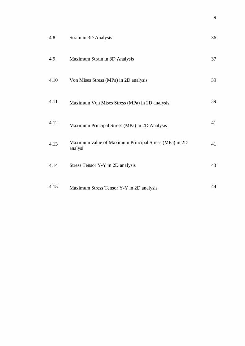
4.8 Strain in 3D Analysis 36
4.9 Maximum Strain in 3D Analysis 37
4.10
4.11
4.12
4.13
4.14
4.15
Von Mises Stress (MPa) in 2D analysis Maximum Von Mises Stress (MPa) in 2D analysis Maximum Principal Stress (MPa) in 2D Analysis Maximum value of Maximum Principal Stress (MPa) in 2D analysi Stress Tensor Y-Y in 2D analysis Maximum Stress Tensor Y-Y in 2D analysis
39
39
41
41
43
44
10
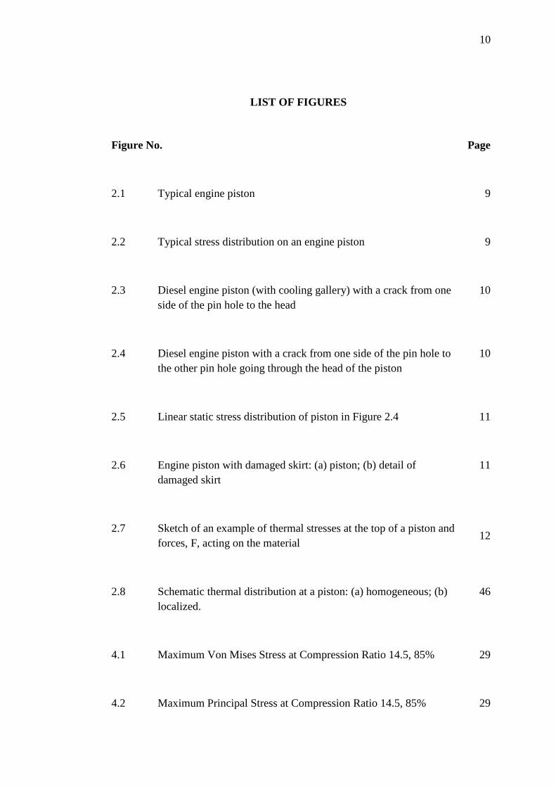
LIST OF FIGURES
Figure No. Page
2.1 Typical engine piston 9
2.2 Typical stress distribution on an engine piston 9
2.3 Diesel engine piston (with cooling gallery) with a crack from one side of the pin hole to the head
10
2.4 Diesel engine piston with a crack from one side of the pin hole to the other pin hole going through the head of the piston
10
2.5 Linear static stress distribution of piston in Figure 2.4 11
2.6 Engine piston with damaged skirt: (a) piston; (b) detail of damaged skirt
11
2.7 Sketch of an example of thermal stresses at the top of a piston and forces, F, acting on the material
12
2.8 Schematic thermal distribution at a piston: (a) homogeneous; (b) localized.
46
4.1 Maximum Von Mises Stress at Compression Ratio 14.5, 85% 29
4.2 Maximum Principal Stress at Compression Ratio 14.5, 85% 29
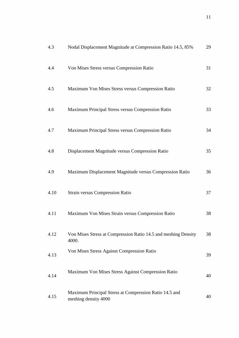
11
4.3 Nodal Displacement Magnitude at Compression Ratio 14.5, 85% 29
4.4 Von Mises Stress versus Compression Ratio 31
4.5 Maximum Von Mises Stress versus Compression Ratio 32
4.6
Maximum Principal Stress versus Compression Ratio
33
4.7 Maximum Principal Stress versus Compression Ratio 34
4.8
4.9
4.10
4.11
4.12
4.13
4.14
4.15
Displacement Magnitude versus Compression Ratio
Maximum Displacement Magnitude versus Compression Ratio
Strain versus Compression Ratio
Maximum Von Mises Strain versus Compression Ratio
Von Mises Stress at Compression Ratio 14.5 and meshing Density 4000.
Von Mises Stress Against Compression Ratio
Maximum Von Mises Stress Against Compression Ratio
Maximum Principal Stress at Compression Ratio 14.5 and meshing density 4000
35
36
37
38
38
39
40
40
12
4.16
4.17
4.18
4.19
4.20
Maximum Principal Stress against Compression Ratio
Maximum Principal Stress versus Compression Ratio
Maximum Stress Tensor Y-Y at Compression Ratio 14.5 and Meshing Density 4000
Stress Tensor Y-Y against Compression Ratio
Maximum Stress Tensor Y-Y against Compression Ratio
41
42
42
43
44
.
13
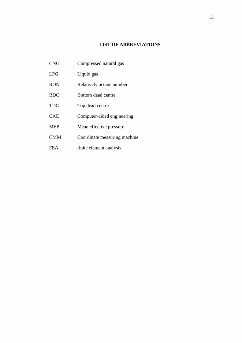
LIST OF ABBREVIATIONS
CNG Compressed natural gas
LPG Liquid gas
RON Relatively octane number
BDC Bottom dead centre
TDC Top dead centre
CAE Computer-aided engineering
MEP Mean effective pressure
CMM Coordinate measuring machine
FEA finite element analysis
APPENDIX AMPLE OF LIST OF
14
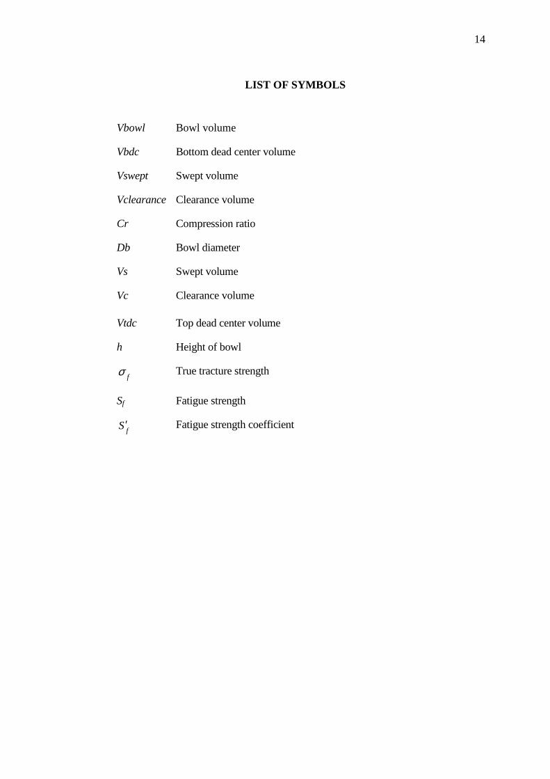
LIST OF SYMBOLS
Vbowl Bowl volume
Vbdc Bottom dead center volume
Vswept Swept volume
Vclearance Clearance volume
Cr Compression ratio
Db Bowl diameter
Vs Swept volume
Vc Clearance volume
Vtdc Top dead center volume
h Height of bowl
fσ True tracture strength
Sf Fatigue strength
fS′ Fatigue strength coefficient
15
CHAPTER 1
INTRODUCTION
1.1 Background
Global environment pollution gives effect to many health problems world
wide. Therefore extensive studies have been conducted all over the world to use
alternative fuels such as alcohol, ether and gaseous fuels (CNG & LPG) which can
reduce the air pollution level by existing fuels (Petrol & Diesel) & bring a sigh of
relief. CNG means Compressed Natural Gas. Its main constituents are Methane (90-
95%) & marginal quantities of Propane, Iso-Butane & Butane. Natural Gas is stored
in cylinders under high pressure of about 200 bars.
CNG is cheaper in price thus saves more on compared to petrol and diesel.
Another advantage of having high octane number is drastic reduction in pollution
thus making CNG less dangerous. In case of leakage it dissipates very easily in air as
it is lighter than air & risk of any hazard is considerably reduced and CNG is
available. CNG is available in abundant quantity in the earth's crust. It leads to higher
thermal efficiency. It is non toxic.
In recent years, CNG has been promoted as a promising clean fuel alternative
to spark ignition engines because of its relatively higher octane level. Due to its high
research octane number (RON>130), CNG allows the combustion at higher
compression ratio without knocking. It also offers much lower greenhouse gas
emissions than those from the burning of other hydrocarbons as a result of its higher
hydrogen to carbon ratio. Recently, the exact understanding of the physical and
chemical processes is required to speed up the design process due to the increasing
market demands of making new engines.
16
1.2 Problem Statement
• 2D analysis using 8 types of meshing density and for 3D analysis using 4
types meshing percentage.
• The compression ratio is range 12- 17.
1.3 Objective
� To design piston model 2D and 3D appropriate with real dimension.
� To analyze the design with finite element analysis (FEA)
1.4 Project Scope
� Modification of piston diesel engine.
� To understand the function of piston and its material properties.
� To convert the diesel engine into CNG engine.

17
1.4 Gantt Chart FYP 1
GANTT CHART/ PROJECT SCHEDULE FOR FYP 1 PROJECT ACTIVITIES WEEKS 1 2 3 4 5 6 7 8 9 10 11 12 13 14 15 16 1 Discuss on the title of the FYP
1
2 Discuss on the objectives and the scopes of the FYP 1
3 Chapter 1 include the objectives, scopes, and the problem statements
4 Submit the chapter 1. Discuss on the format of project
5 Literature study. Find the information related to the literature review
6 Discuss on chapter 2, the literature review, journal and related information
7 Chapter 2.1, the introduction of piston.
8 Discuss on chapter 2.1 9 Chapter 2.2, introduction of
CAE and CAD and method analysis
10 Discuss on the analysis and the methodology
11 Chapter 3, The methodology 12 Preparation for the presentation
Table 1.1: Gantt Chart/ Project Schedule For FYP 1
18
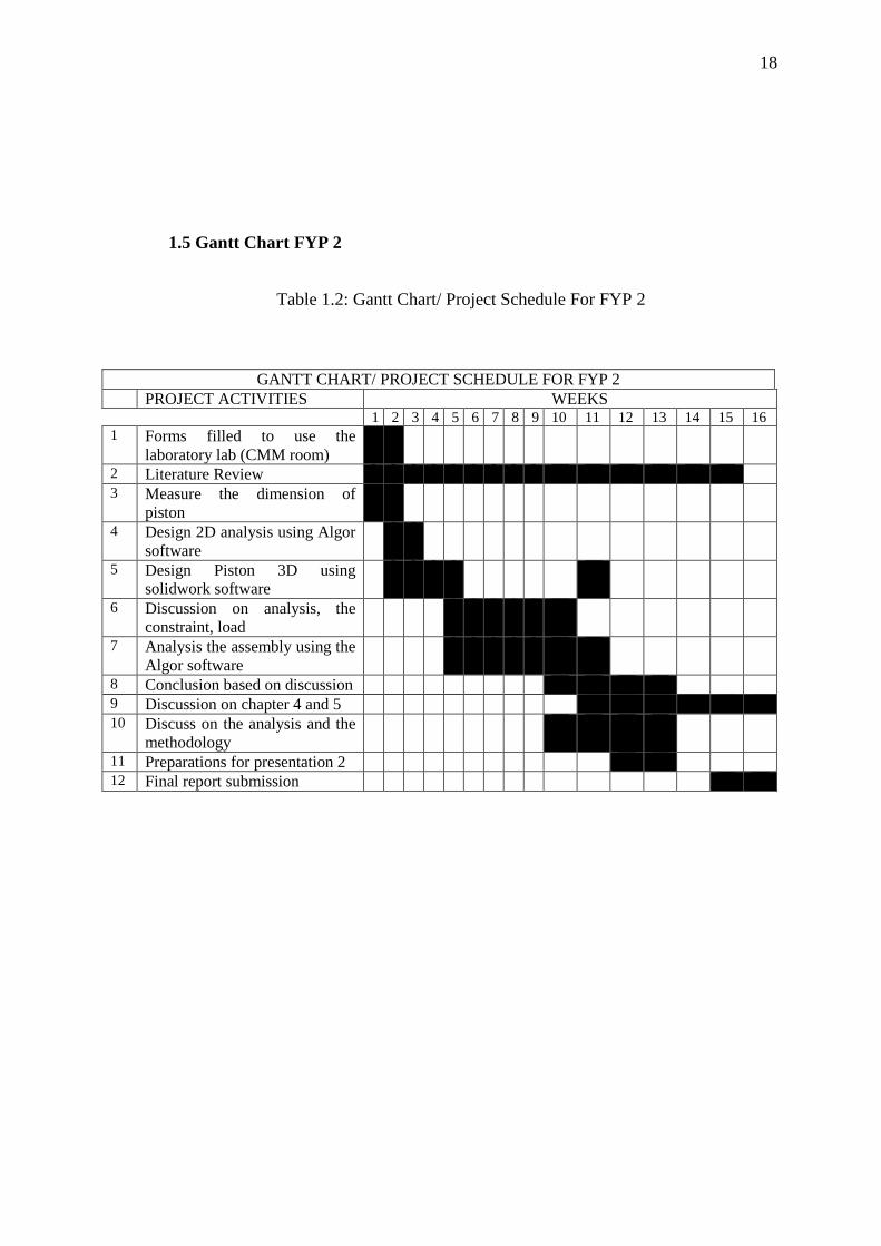
1.5 Gantt Chart FYP 2
GANTT CHART/ PROJECT SCHEDULE FOR FYP 2 PROJECT ACTIVITIES WEEKS 1 2 3 4 5 6 7 8 9 10 11 12 13 14 15 16 1 Forms filled to use the
laboratory lab (CMM room)
2 Literature Review 3 Measure the dimension of
piston
4 Design 2D analysis using Algor software
5 Design Piston 3D using solidwork software
6 Discussion on analysis, the constraint, load
7 Analysis the assembly using the Algor software
8 Conclusion based on discussion 9 Discussion on chapter 4 and 5 10 Discuss on the analysis and the
methodology
11 Preparations for presentation 2 12 Final report submission
Table 1.2: Gantt Chart/ Project Schedule For FYP 2
19
CHAPTER 2
LITERATURE REVIEW
2.1 COMPRESSED NATURAL GAS (CNG)
2.1.1 Typical composition of natural gas
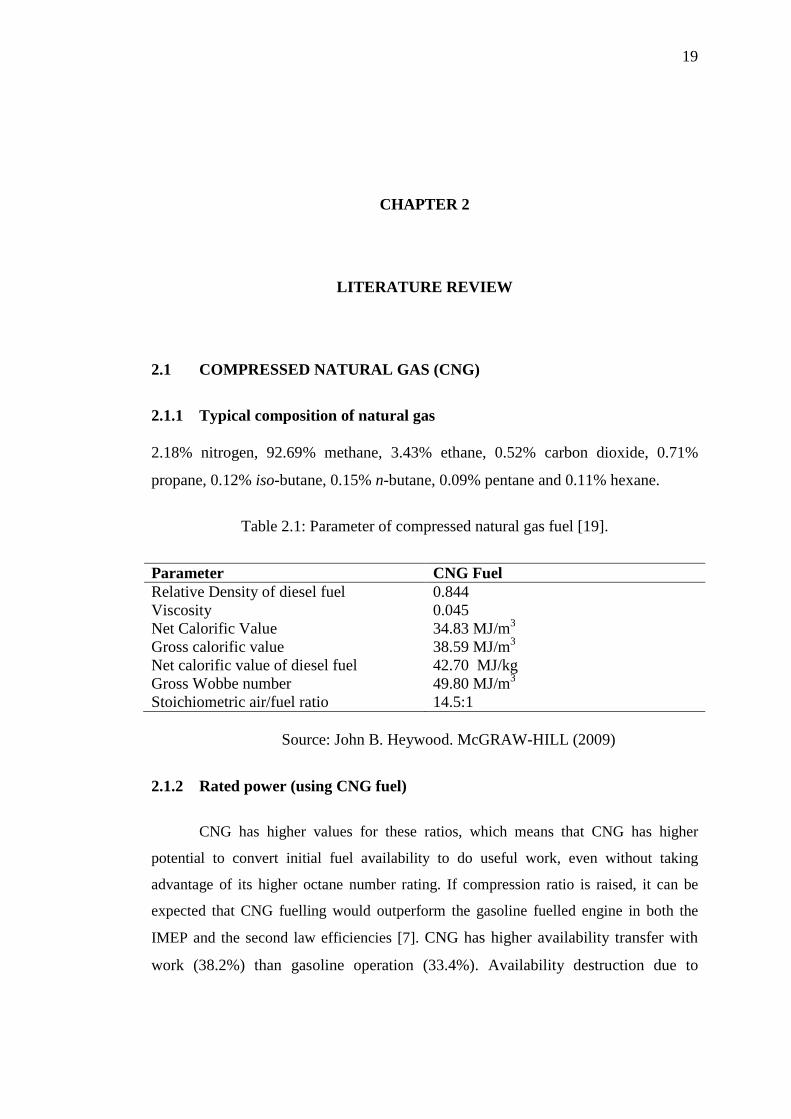
2.18% nitrogen, 92.69% methane, 3.43% ethane, 0.52% carbon dioxide, 0.71%
propane, 0.12% iso-butane, 0.15% n-butane, 0.09% pentane and 0.11% hexane.
Table 2.1: Parameter of compressed natural gas fuel [19].
Parameter CNG Fuel Relative Density of diesel fuel 0.844 Viscosity 0.045 Net Calorific Value 34.83 MJ/m3 Gross calorific value 38.59 MJ/m3 Net calorific value of diesel fuel 42.70 MJ/kg Gross Wobbe number 49.80 MJ/m3 Stoichiometric air/fuel ratio 14.5:1
Source: John B. Heywood. McGRAW-HILL (2009)
2.1.2 Rated power (using CNG fuel)
CNG has higher values for these ratios, which means that CNG has higher
potential to convert initial fuel availability to do useful work, even without taking
advantage of its higher octane number rating. If compression ratio is raised, it can be
expected that CNG fuelling would outperform the gasoline fuelled engine in both the
IMEP and the second law efficiencies [7]. CNG has higher availability transfer with
work (38.2%) than gasoline operation (33.4%). Availability destruction due to

20
combustion is about the same for CNG and gasoline. However, availability
destruction due to heat transfer is lower with CNG operation (13.8%).
2.2 EXPERIMENTAL REVIEW
2.2.1 Setup and Procedures
Referring to research conducted by Ke Zheng etall [6], A single cylinder
engine was modified into a natural gas direct-injection engine. To increase the flow
rate for natural gas application, the swirler near the tip of nozzle was taken off.
Natural gas is injected into cylinder at the constant pressure of 8 MPa. Besides
installing the natural gas high-pressure injector, a spark plug is also installed into the
centre of combustion chamber as the ignition source.
Table 2.2: Engine specifications [6]
Engine specifications Bore (mm) 100 Stroke (mm) 115 Displacement (cm3) 903 Compression ratio 8 Injection pressure (MPa) 8 Ignition source Spark plug Combustion chamber Bowl-in-shape
Source: Ke Zeng, Zuohua Huang (2006)
2.3 INTERNAL COMBUSTION ENGINE
The compressed ignition or diesel engine had been developed by Rudolf
Diesel in 1892 [1]. The normal internal combustion engine is generally one of two
types, spark ignition petrol or gas engines and diesel engine [2]. In this engine, the
piston reciprocates in the cylinder between two fixed position called the top dead
centre (TDC) and the bottom dead centre (BDC) [3][4]. TDC is the position of the
piston when it forms the smallest volume in cylinder and BDC is the position of the
piston when it forms the largest volume in the cylinder. The distance between TDC
21
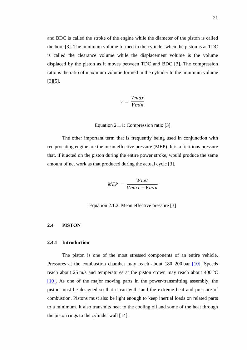
and BDC is called the stroke of the engine while the diameter of the piston is called
the bore [3]. The minimum volume formed in the cylinder when the piston is at TDC
is called the clearance volume while the displacement volume is the volume
displaced by the piston as it moves between TDC and BDC [3]. The compression
ratio is the ratio of maximum volume formed in the cylinder to the minimum volume
[3][5].
� � �������
Equation 2.1.1: Compression ratio [3]
The other important term that is frequently being used in conjunction with
reciprocating engine are the mean effective pressure (MEP). It is a fictitious pressure
that, if it acted on the piston during the entire power stroke, would produce the same
amount of net work as that produced during the actual cycle [3].
�� � ������ � ���
2.4 PISTON
2.4.1 Introduction
The piston is one of the most stressed components of an entire vehicle.
Pressures at the combustion chamber may reach about 180–200 bar [10]. Speeds
reach about 25 m/s and temperatures at the piston crown may reach about 400 °C
[10]. As one of the major moving parts in the power-transmitting assembly, the
piston must be designed so that it can withstand the extreme heat and pressure of
combustion. Pistons must also be light enough to keep inertial loads on related parts
to a minimum. It also transmits heat to the cooling oil and some of the heat through
the piston rings to the cylinder wall [14].
Equation 2.1.2: Mean effective pressure [3]
22
Notwithstanding this technological evolution there are still a significant
number of damaged pistons. Damages may have different origins: mechanical
stresses, thermal stresses, wear mechanisms, temperature degradation, oxidation
mechanisms and etc. Fatigue is a source of piston damages. Although, traditionally,
piston damages are attributed to wear and lubrication sources, fatigue is responsible
for a significant number of piston damages. And some damages where the main
cause is attributed to wear and/or lubrication mechanisms may have in the root cause
origin a fatigue crack.
Fatigue exists when cyclic stresses/deformations occur in an area on a
component. The cyclic stresses/deformations have mainly two origins: load and
temperature. Traditional mechanical fatigue may be the main damaging mechanism
in different parts of a piston depending on different factors. High temperature fatigue
(which includes creep) is also present in some damaged pistons. Thermal fatigue and
thermal–mechanical fatigue are also present in other damaged pistons. A finite
element linear static analysis, using “cosmos works”, is used for stress and
temperature determination. Only aluminum pistons are assessed in this work because
most of the engine pistons are in aluminum.
The fatigue-damaged pistons may be divided into two categories: the
mechanical and high temperature mechanical damaged pistons and the thermal and
thermal–mechanical damaged pistons. The mechanical and high temperature
mechanical damaged pistons may be divided according to the damaged area: piston
head; piston pin holes; piston compression ring grooves; and piston skirt. The
analysis, in this work, will be made according to this classification.
2.4.2 Mechanical and high temperature mechanical fatigue
By mechanical fatigue means that in a piston a crack will nucleate and
propagate in critical stressed areas. The stresses in this context are due to the loads
acting externally on the piston. Although stresses on pistons change with piston
geometries and engine pressures, Figure 2.1 and Figure 2.2 show a typical stress
distribution on an engine piston. In Figure 2.1 and Figure 2.2 pressures are merely
indicative and are used only with the purpose of determination of the most stressed

23
areas. It is not intended to determine the real stresses acting on the piston. The
dynamic and thermal stresses are not also included in Figure 2.1 and Figure 2.2.
Figure 2.1: Typical engine piston [14]
Figure 2.2: Typical stress distribution on an engine piston [14].
It is clear that there are mainly two critical areas: the top side of piston pin
hole and two areas at the piston head. Stress analyses on diesel pistons show the
same critical areas. If holes or grooves are introduced on the pin hole it is possible to
introduce critical stressed areas on those discontinuities.

24
2.4.3 Piston head and piston pin hole
As observed in Figure 2.1 and Figure 2.2, due to the pressure at the piston
head, there are mainly two critical areas: piston pin holes and localized areas at the
piston head. On pistons in Figure 2.3 and Figure 2.4 the cracks initiated on the piston
head near the combustion chamber.
Figure 2.3: Diesel engine piston (with cooling gallery) with a crack from one
side of the pin hole to the head [14]
Figure 2.4: Diesel engine piston with a crack from one side of the pin hole to the other pin hole going through the head of the piston [14].